Embed Size (px)
Citation preview
INTERPRETATION REPORT
INTERPRETATION OF AIRBORNE AEROTEM EM DATAPARKIN OFFSET PROPERTYSUDBURY AREA, ONTARIO
FOR
CHAMPION BEAR RESOURCES LTD.2005,9th ST. SW
CALGARY, ALBERTA T2T 3C4
BY
GEODATEM AIRBORNE CONSULTANTS28 WESTVIEW CRESCENT
PALGRAVE, ONTARIO LON 1PO
ROBERT J. DE CARLE AUGUST 30,2002
oftt V
-^
G1602 "RECEIVEDpro 4 n ^,-lC,Ui-.v^ i u i^UU
SEOSClENCf ASSESSMENT
41I15SW2057 2.26827 PARKIN 010
TABLE OF CONTENTS
1. INTRODUCTION................................................................................l
2. PROJECT LOCATION ........................................................................2
3. SURVEY OPERATIONS....................................................................^3.1 System Parameters...........................................................................3
4. AIRCRAFT AND EQUIPMENT........................................................^4.1 Aircraft.............................................................................................44.2 Survey Personnel.............................................................................54.3 Equipment........................................................................................5
4.3.1 Electromagnetic System..........................................................54.3.2 Magnetometer..........................................................................5
4.4 Ancillary Systems............................................................................64.4.1 Magnetometer and OPS Base Station .....................................64.4.2 Radar Altimeter.......................................................................64.4.3 Video Tracking and Recording System.................................. 74.4.4 OPS Navigation System..........................................................?4.4.5 Digital Acquisition System.....................................................?
5. DATA PRESENTATION....................................................................^5.1 Electromagnetic Data.......................................................................85.2 Magnetic Data.................................................................................. 8
6. INTERPRETATION............................................................................^6.1 Geology............................................................................................96.2 Magnetics.......................................................................................106.3 AEROTEM....................................................................................13
7. CONCLUSIONS AND RECOMMENDATIONS.............................l5
APPENDIX I REFERENCESAPPENDIX II CERTIFICATE OF QUALIFICATIONSAPPENDK III CASE HISTORY
1. INTRODUCTION
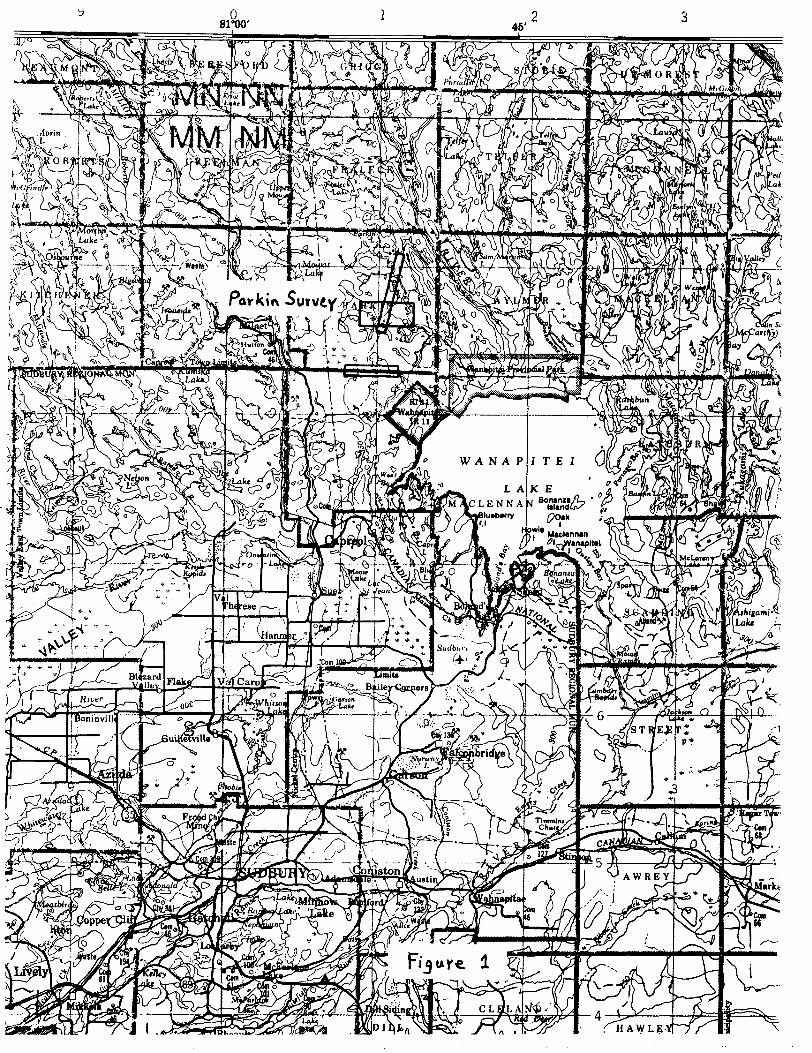
This report details the operation and interpretation of two helicopter-borne electromagnetic and magnetic surveys flown for Champion Bear Resources Ltd. on March 21, 2001 and June 6, 2002, over a block of ground in the Parkin Township area, Ontario (Figure 1). The system used for both surveys was the Aeroquest AEROTEM time domain EM system.
Joe Hinzer of Watts, Griffis and McQuat Limited, geological consultants for Champion Bear Resources Ltd., commissioned the interpretation of this airborne data on May 7, 2002.
The primary objective for carrying out these surveys was to locate mineralized Ni-Cu-PGE zones, which can be directly or indirectly related to either Whistle or Foy-type offset dikes. Of importance in this survey area will be the Parkin Offset Dike, which contains the former Milnet Mine, the Northbridge Zones and the former Whistle Mine to the south.
In reference to the electromagnetic data, the writer will pay particular attention to strong EM responses that may reflect moderate or steeply dipping conductors associated with the offset dike. Also of interest will be poorly mineralized zones that may reflect disseminated sulphides within a footwall environment.
Interpretation of the magnetic data may reveal the existence of structural effects, cross-cutting lithological patterns, and possible zones of pyrrhotite and magnetite within the offset dike.
This survey (2002) consisted of 54 kilometres of traverse and tie lines (North Block) and 16 kilometres of nearby test lines (South Block). The 2001 airborne survey to the north consisted of 50 kilometres of traverse lines.
2. PROJECT LOCATION
The survey area is depicted on the index map as shown (Figure 1), and referenced to NTS 411 15. It is centered in south central Parkin Township at Latitude 46 degrees 50 minutes north, Longitude 80 degrees 52 minutes west, approximately 38 kilometres north-northeast of Sudbury, Ontario. The survey block is also located northwest of Wanapitei Lake and roughly 6.5 kilometres east of the village of Milnet.
Access to the region can be made via Highway 69 from Sudbury, and then via Highway 545 from Capreol. Numerous secondary roads lead into the survey area from the village of Milnet.
3. SURVEY OPERATIONS
Nominal EM bird terrain clearance was 25 metres. The magnetometer sensor was mounted in a smaller bird connected to the tow rope 21 metres above the EM bird and 17 metres below the helicopter. Nominal survey speed was 75 km/hr. Scan rates for data acquisition was 0.1 second for the magnetometer, electromagnetics and altimeter and l .0 second for the OPS determined position. This translates to a geophysical reading about every 2 metres along flight track.
Navigation was assisted by a OPS receiver and the RMS data acquisition system which reports OPS co-ordinates as WGS-84 latitude/longitude and directs the pilot over a pre-programmed survey grid. The x-y-z position of the aircraft, as reported by the OPS, is recorded at one second intervals. The OPS positions were differentially corrected in real time using the RACAL satellite based system.
Unlike frequency domain electromagnetic systems, the AEROTEM system has negligible drift due to thermal expansion and therefore high altitude zero calibration lines are not required. The inherent static offset is removed by identifying areas of no response and employing local leveling lines.
The operator was responsible for ensuring the instrument was properly warmed up prior to departure and that the instruments operated properly throughout the flight. He also maintained a detailed flight log during the survey noting the times of the flight as well as any unusual geophysical or topographic features.
On return of the aircrew to the base camp, the RMS acquisition system survey data on ZipDisk was downloaded to the data processing work station. The MDAS recorded data on JazzDisk was also downloaded to the processing station for back-up purposes. In-field processing included flight preparation, transfer of the RMS acquired data to Geosoft GDB database format and production of preliminary EM, magnetic contour, and flight path maps. Survey lines which showed excessive deviation after differential correction were reflown.
3.1 System Parameters
System Characteristics:
Transmitter:Triangular Pulse Shape Base Frequency 30 or 150 Hz.Tx On Time : 5,750 (30Hz) or 1,150 (150Hz) msec.Tx Off Time : 10,915 (30Hz) or 2,183 (150Hz) msec.Loop Diameter: 5 metres.Peak Current: 250 Amp.Peak Moment: 40,000 NIA.Typical Z Axis Noise at Survey Speed : 8 ppb peak.Sling Weight: 270 Kg.Length of Tow Cable : 40 metres.Bird Survey Height: 30 metres or less nominal.
Receiver:Three Axis Receiver Coils (x,y,z) positioned at center oftransmitter loop.Selectable Time Delay to start of first channel 20,40, or 60 msec.
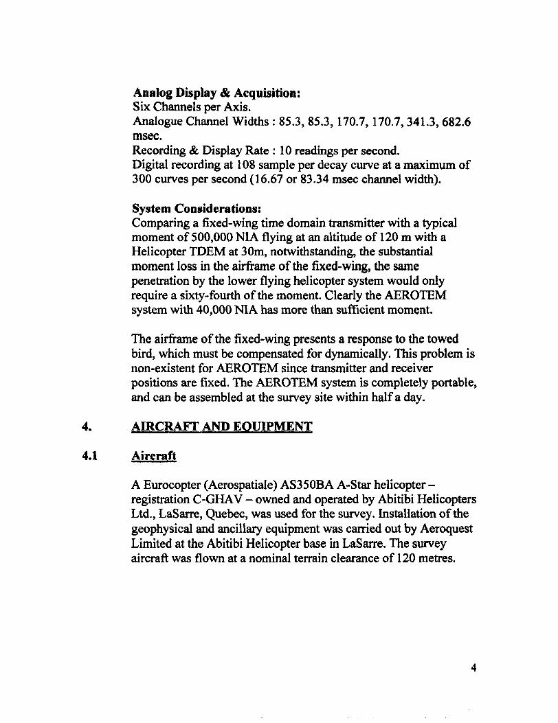
Analog Display A Acquisition:Six Channels per Axis.Analogue Channel Widths : 85.3, 85.3, 170.7, 170.7, 341.3, 682.6msec.Recording 8c Display Rate : 10 readings per second.Digital recording at 108 sample per decay curve at a maximum of300 curves per second (16.67 or 83.34 msec channel width).
System Considerations:Comparing a fixed-wing time domain transmitter with a typical moment of 500,000 NIA flying at an altitude of 120 m with a Helicopter TDEM at 30m, notwithstanding, the substantial moment loss in the airframe of the fixed-wing, the same penetration by the lower flying helicopter system would only require a sixty-fourth of the moment. Clearly the AEROTEM system with 40,000 NIA has more than sufficient moment.
The airframe of the fixed-wing presents a response to the towed bird, which must be compensated for dynamically. This problem is non-existent for AEROTEM since transmitter and receiver positions are fixed. The AEROTEM system is completely portable, and can be assembled at the survey site within half a day.
4. AIRCRAFT AND EQUIPMENT
4.1 Aircraft
A Eurocopter (Aerospatiale) AS350BA A-Star helicopter - registration C-GHAV - owned and operated by Abitibi Helicopters Ltd., LaSarre, Quebec, was used for the survey. Installation of the geophysical and ancillary equipment was carried out by Aeroquest Limited at the Abitibi Helicopter base in LaSarre. The survey aircraft was flown at a nominal terrain clearance of 120 metres.

4.2 Survey Personnel
The survey crew was made up of experienced employees:
Pilot: Joel Breton Operator/technician: Bert Simon
4.3 Equipment
43.1 Electromagnetic System
The electromagnetic system employed was an Aeroquest AEROTEM Time Domain towed bird system. It is currently the only commercially available helicopter TDEM system using a coincident Tx-Rx loop combination. Six channels of the off-time EM decay are measured in two components, ie. The x and z directions. Although both x and z components of the decay field were recorded, only the z component data is presented in the final maps (although x l appears in the stacked profiles). The transmitted waveform is triangular with a base frequency of ISOHz., yielding 300 decays per second. The Transmitter Dipole Moment is 48,000 NIA. The AEROTEM bird was towed 38 metres below the helicopter. More technical details of the system may be found in Section 3.1.
43.2 Magnetometer
The Aeroquest airborne survey system employed the Geometrics G-822A cesium vapour magnetometer sensor installed in a two metre towed bird airfoil attached to the main tow line, 17 metres below the helicopter. The sensitivity of the magnetometer is 0.001 nanoTesla at a 0.1 second sampling rate. The nominal ground clearance of the magnetometer bird was 51 metres.
4.4 Ancillary Systems
4.4.1 Magnetometer and GPS Base Station
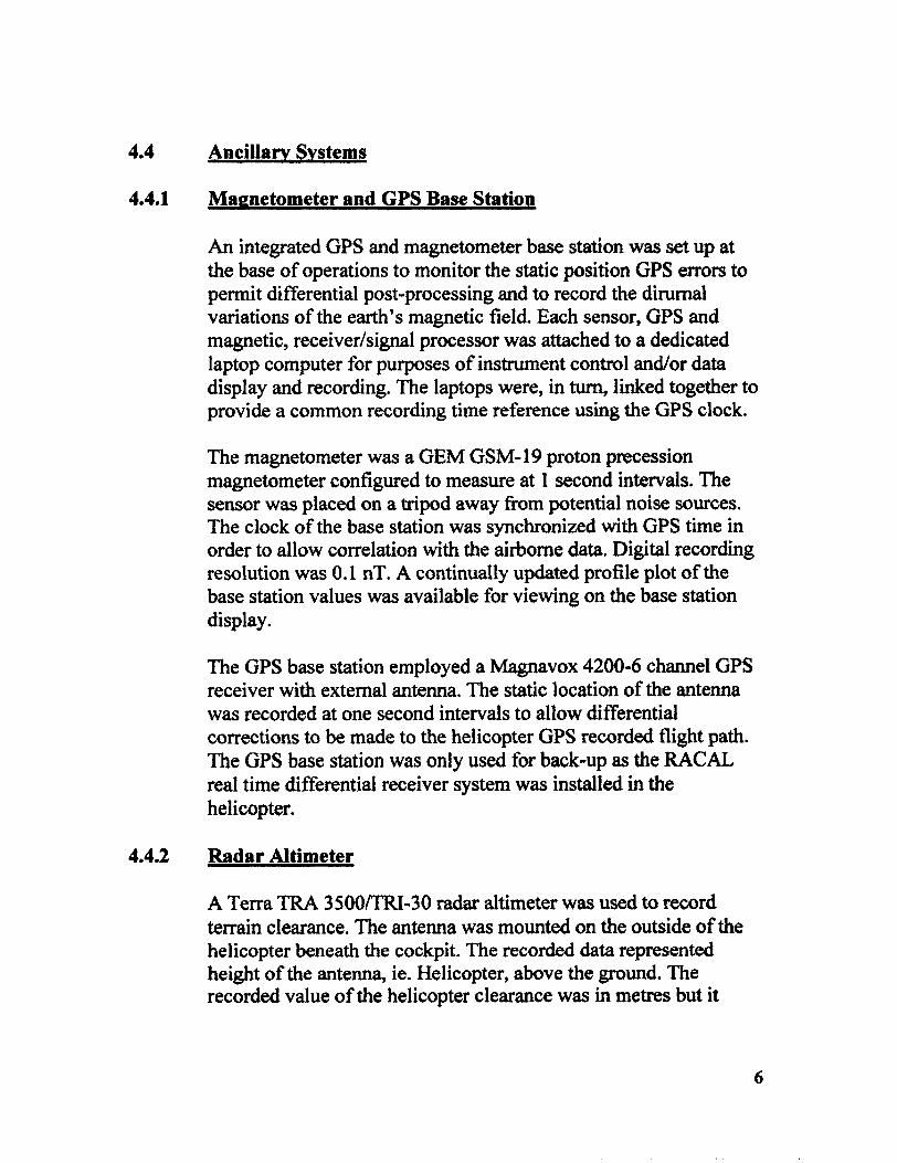
An integrated GPS and magnetometer base station was set up at the base of operations to monitor the static position GPS errors to permit differential post-processing and to record the dirumal variations of the earth's magnetic field. Each sensor, GPS and magnetic, receiver/signal processor was attached to a dedicated laptop computer for purposes of instrument control and/or data display and recording. The laptops were, in turn, linked together to provide a common recording time reference using the GPS clock.
The magnetometer was a GEM GSM-19 proton precession magnetometer configured to measure at l second intervals. The sensor was placed on a tripod away from potential noise sources. The clock of the base station was synchronized with GPS time in order to allow correlation with the airborne data. Digital recording resolution was 0.1 nT. A continually updated profile plot of the base station values was available for viewing on the base station display.
The GPS base station employed a Magnavox 4200-6 channel GPS receiver with external antenna. The static location of the antenna was recorded at one second intervals to allow differential corrections to be made to the helicopter GPS recorded flight path. The GPS base station was only used for back-up as the RACAL real time differential receiver system was installed in the helicopter.
4.4.2 Radar Altimeter
A Terra TRA 3500/TRI-30 radar altimeter was used to record terrain clearance. The antenna was mounted on the outside of the helicopter beneath the cockpit. The recorded data represented height of the antenna, ie. Helicopter, above the ground. The recorded value of the helicopter clearance was in metres but it
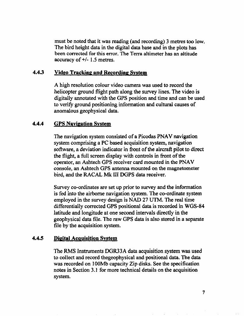
must be noted that it was reading (and recording) 3 metres too low. The bird height data in the digital data base and in the plots has been corrected for this error. The Terra altimeter has an altitude accuracy of +S- 1.5 metres.
4.43 Video Tracking and Recording System
A high resolution colour video camera was used to record the helicopter ground flight path along the survey lines. The video is digitally annotated with the OPS position and time and can be used to verify ground positioning information and cultural causes of anomalous geophysical data.
4.4.4 GPS Navigation System
The navigation system consisted of a Picodas PNAV navigation system comprising a PC based acquisition system, navigation software, a deviation indicator in front of the aircraft pilot to direct the flight, a full screen display with controls in front of the operator, an Ashtech GPS receiver card mounted in the PNAV console, an Ashtech GPS antenna mounted on the magnetometer bird, and the RACAL Mk III DGPS data receiver.
Survey co-ordinates are set up prior to survey and the information is fed into the airborne navigation system. The co-ordinate system employed in the survey design is NAD 27 UTM. The real time differentially corrected GPS positional data is recorded in WGS-84 latitude and longitude at one second intervals directly in the geophysical data file. The raw GPS data is also stored in a separate file by the acquisition system.
4.4.5 Digital Acquisition System
The RMS Instruments DGR33A data acquisition system was used to collect and record thegeophysical and positional data. The data was recorded on 100Mb capacity Zip disks. See the specification notes in Section 3.1 for more technical details on the acquisition system.

5. DATA PRESENTATION
5.1 Electromagnetic Data
A two stage digital filtering process was used to reject major sferic events and to reduce system noise.
Local sferic activity can produce sharp, large amplitude events that cannot be removed by conventional filtering procedures. Smoothing or stacking will reduce their amplitude but leave a broader residual response that can be confused with geological phenomena. To avoid this possibility, a computer algorithm searches out and rejects the major sferic events. The filter used was a 0.8 sec. Non-linear filter.
The signal to noise ratio was further improved by the application of a low pass linear digital filter. This filter has zero phase shift which prevents any lag or peak displacement from occurring, and it suppresses only variations with a wavelength less than about 2 seconds or 40 metres. This filter is referred to as a 2.0 sec linear filter.
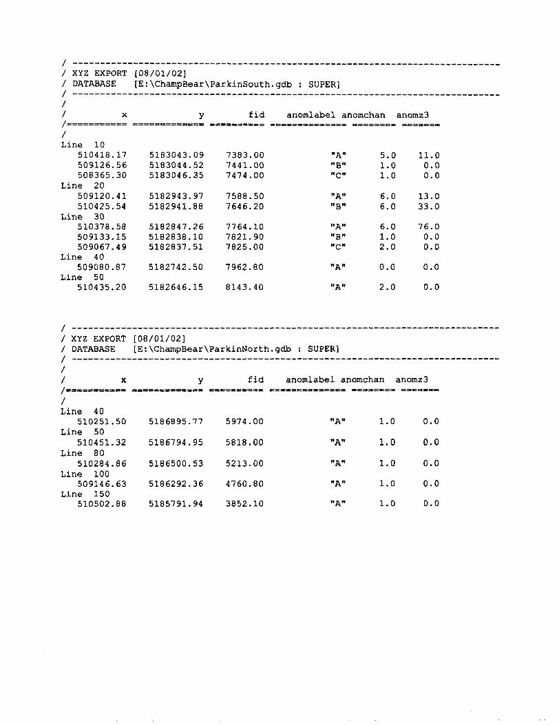
EM anomalies have been manually picked from the analogue profiles. Each anomaly has been given a letter label and is graded according to the channel in which the anomaly is discernible and the direction of the excursion, either positive or negative. A listing of these anomalies may be found in the appendix.
The EM channels have been leveled to remove the residual zero offset
5.2 Magnetic Data
The aeromagnetic data were corrected for diurnal variations by adjustment using the magnetic base station and, where necessary, the intersections of the tie lines. No corrections for the regional reference field (IGRF) were applied. The corrected profile data were interpolated on to a grid using a random grid technique.

The cell size was 10 metres for the l: 10,000 grid. Any leveling errors still apparent in the magnetic grid were removed by micro- levelling which involves the use of a frequency domain directional filter. The final leveled grid provided the basis for threading the presented contours. The minimum contour interval was 10 nT.
6. INTERPRETATION
6.1 Geology
The offset dikes of the Offset Sublayer either extend approximately radially from the Sudbury Igneous Complex or lie concentrically in the country rocks. Quartz diorite is the dominant rock type and, as with the Contact Sublayer of the Sudbury Igneous Complex, is characterized by a variety of inclusions and low sulphide mineralization.
Three types of quartz diorite occur in the dikes, hypersthene quartz diorite, two-pyroxene quartz diorite and amphibole-biotite quartz diorite.
Sulphide minerals appear to be spatially, and possibly also genetically, associated with mafic and ultramafic exotic inclusions. This association and the intermediate composition of the quartz diorite suggest that the quartz diorite was not the source for the sulphides. The mineralization was passively transported to its present position by the quartz diorite magma. Ore bodies in offset dikes tend to occur in areas of high inclusion/fragment concentration, as well as areas of geometric change of the host dikes.
The offset dike within this survey area is referred to as the Parkin Offset and would appear to be the north extention of the Whistle Offset, where the former Whistle Mine is located.
The Parkin Offset dike traverses in a north-northeast direction through the survey block and is known to extend well to the north. Gossan zones have been located along some portions of the dike.
Within the North Block, several drill holes were put down by Falconbridge Limited in 1999, but the results are not known to this writer.
To the south of the North Block, the Milnet Mine of Jonsmith Mines Limited contained two nickel-copper deposits. South again from the Milnet Mine, two mineralized Cu-Ni zones were worked on by both Falconbridge Nickel Mines Limited and Northbridge Mines Limited from 1934 to 1998. Both of these zones are presently being worked on by Wallbridge Mining Ltd. A recent reserve estimate of the Northbridge Zone l gives results of 178,000 tons of G.71% Cu, Q.65% Ni, 0.66 g/ton Pt, 0.85 g/ton Pd, 0.25 g/ton Au and G.03% Co. The former producing Whistle Mine of INCO Limited contained 5.71 million tons of 0.3307o Cu, G.95% Ni and 3.4 g/ton PGE. This property is presently being worked on by FNX Mining Ltd.
6.2 Magnetics
North Block
The aeromagnetic data clearly shows a variance in the magnetic intensity within the survey area, ranging from 57,011 nT in the regions of the Serpent and Mississagi Formations in the south and the Lorrain Formation in the north to as high as 58,175 nT over areas considered to be underlain with Nipissing diabase.
Areas exhibiting the larger magnetic anomalies are interpreted as being underlain with the Nipissing diabase (ND). The magnetic response is either directly related to the diabase or to magnetite within an alteration rock type near the contact between the diabase and the Gowganda Formation (GF).
Towards the southwest corner of the 2002 survey, the region of low magnetic intensity appears to be associated with both the Mississagi (MF) and Serpent (SF) Formations. However, there may be some diabase intruding these sediments and that is giving rise to a few, higher intensity magnetic responses. Towards the
10
north end of the 2001 survey, the region of low magnetic intensity is associated with the Lorrain Formation (LF).
The longer, narrower magnetic trends are contained within the Gowganda Formation. It has been noted that there are lenses of magnetite within the argillite sequence. These can probably be best observed in the eastern portion of the 2002 survey. There are also a few such horizons in the 2001 survey as well.
There is only one area that has been interpreted as an olivine diabase (OD) dike. This is located near the center of the north boundary of the 2002 survey. The anomaly was basically isolated as a result of the 2nd derivative and then confirmed from the geology map.
It is very clear that the areas displaying the higher intensity magnetic features have been broken up into unique trends as a result of the computation of the 2nd vertical derivative. However, it should also be noted that rock types that exhibit extremely poor magnetic susceptibility would be enhanced as well. This would appear to be the case for the Parkin Offset (PO) dike, which seems to exhibit magnetic intensities of less than 10 nT. If by chance the Parkin Offset dike has been intruded into the Nipissing diabase, then the higher magnetic susceptibility of the latter may dominate and thus mask the magnetic effects from the Parkin Offset dike.
In reference to a geological map by Champion Bear, there seems to be good correlation between the Parkin Offset dike and the 2nd vertical derivative near the south central region of the 2002 survey. Drill Hole P-15 went through the dike, but P-10 did not. On the other hand, Drill Hole P-11 went through the dike, but unfortunately, it would appear that it missed what is suspected to be a good EM conductor just a short distance to the norm,
Further to the north, the Parkin Offset (PO) dike has been interpreted from the 2nd derivative data and outlined on the Interpretation Map overlay. It was not obvious from the total field data. There appears to be a displacement of the dike (B and C on
11
the Interpretation Map overlay) as a result of a fault zone. A drill hole by Falconbridge (P-52) would appear to have intersected an offset portion of the dike, although the geology map shows it missing.
The zero contour interval coincides directly or is very close to where one should find the contacts of the various magnetic bodies. Because of the nature of the Parkin Offset dikes and their probable near vertical contacts, it means that the zero contour intervals are reasonably close to where they will be found on the ground. If, in fact, the zero contour intervals represent the contact of the dikes, then the area of interest for further exploration should be within an area encompassing approximately 100-150 metres away from the contact.
There were a few other weak magnetic trends intercepted towards the eastern extremes of the 2002 survey. These may or may not be other quartz diorite dikes. Because of their similar magnetic susceptibilities as that for the Parkin Offset dikes, one may want to consider a ground reconnaissance survey in these areas. In fact, could there be more than one dike in this region, besides the Parkin Offset dike.
The writer has indicated a few fault zones on the Interpretation Map overlay. These are believed to be post-Archean fault structures and may have affected the mineralizing processes. Because of the nature of the computation of the 2 vertical gradient data, magnetic anomalies produced by sub-surface features have been emphasized with respect to those resulting from more deeply buried rock formations. It is suggested that these are inferred fault zones, as opposed to interpreted fault zones. They may be indications of eventual interpreted faults or upon obtaining further information in the field, they may turn out to be actual fault zones. In any event, they are presented to the client for further scrutiny.
12
South Block
The moderate magnetic intensities in the South Block, where the test lines were flown, are related to mafic metavolcanics and granite. The trend exhibiting the highest magnetic intensity is that of an interpreted sulphide zone, with pyrrhotite being the source of the magnetic response. Zone S2 is considered a potential VMS target on ground held by John Brady.
The Parkin Offset (PO) dike in this area, also known as the Northbridge Zone l, is clearly defined with the 2nd vertical derivative data. It shows that the dike is approximately 100 metres wide at this point, with the strongest magnetic intensity about 150 metres north of the Norman-Parkin Twps. Boundary.
6.3 AEROTEM
The electromagnetic data for both the 2001 and 2002 airborne surveys was first checked by a line-by-line examination of the profile data. Record quality was reasonable with minor noise levels on all EM channels. However, this was readily removed with a smoothing filter. There were also a few 'tweaks' or atmospherics recorded during this survey and these have generally been deleted from the data.
As a result of this airborne survey being carried out, it is very clear that a majority of the survey blocks are overlain with a rather resistive cover. The same can be said for the 2001 airborne survey data.
In order to assess a known mineralized target, which is geologically and mineralogically similar to what is being pursued within the North Block, it was decided to fly a few test lines over the Northbridge Zone l (South Block - Zone SI) of Falconbridge Limited. Wallbridge Mining Ltd. Presently has an option on this latter property.
13
As a result of the test survey, a bedrock conductor of approximate 200 metres strike length was intercepted over the Northbridge Zone 1. It exhibits reasonable conductivity, based on its slow decay rate. Since there are no qualitative nomograms available as yet for the AEROTEM system, both conductivity-width and depth estimates are not available. However, the EM responses, particularly on lines L20, display a somewhat broad EM response, indicating a somewhat deeper source. On some sections of die dike, diamond drilling by Wallbridge Mining has detected sulphide mineralization to a depth of 150 metres. To the north, beneath Malbeuf Lake, ground geophysics (Wallbridge) has detected an EM anomaly at a depth of about 400 metres.
There is also a weaker extention of the Northbridge Zone l to the south (lines L40 and L50), however, these are very poor EM responses (channel l only) and therefore, may not even relate to any mineralization. Also, a very poor anomaly (line L30B) has been selected, based on an inflection on channel 1. It flanks the main conductor on the east side and is located on or near a road.
To the east of Zone SI, a strong conductor (Zone S2) was intercepted on ground that is believed to be held by John Brady of Sudbury. There is also direct magnetic correlation suggesting that pyrrhotite may be the source. The host rocks would appear to be felsic and mafic metavolcanics. No offset dikes are known to be in this area, so this conductor could be a VMS target.
As a result of anomalies being intercepted from a previous AEROTEM survey in 2001 and the success from test flying the Northbridge Zone l deposit, a portion of the large Parkin Property was flown. Interestingly enough however, there were no AEROTEM anomalies intercepted in this survey. A few, very weak EM responses were selected and plotted on the map (North Block), but again these are very poor EM responses. In fact, most if not all of them, are within the 'noise envelope' of the system. Therefore, one should not construe that these anomalies are in any way associated with bedrock sources.
14

In the previous 2001 AEROTEM survey, with flight lines oriented in a N14E direction, two bedrock related anomalies were intercepted (Zone Nl) between lines L80 and L90. However, there were no responses intercepted in this survey on either L80 or L90 that would correlate with this zone. It is very likely that the strike length of this zone is less than 100 metres, which is the survey line spacing, and the strike orientation of the zone is somewhat parallel or at an oblique angle to the flight line direction. In any event, the two flight lines, L80 and L90, missed the zone. For the remainder of the 2001 AEROTEM survey to the north, there were no anomalies intercepted that are bedrock related.
7. CONCLUSIONS AND RECOMMENDATIONS
Based on the results of the 2001 and 2002 airborne electromagnetic and magnetometer (AEROTEM) surveys, ground follow-up is recommended for a few areas as outlined by this writer on the Interpretation Map overlay. These areas are based on both the electromagnetic and magnetic data, namely Zones Nl (EM) and Zones A, B and C (magnetics).
As previously mentioned, Zone Nl was intercepted in the 2001 survey, but was not in the 2002 survey. This phenomenon is probably related to the strike direction of the conductor and the flight line directions of the two airborne surveys. It is definitely a bedrock conductor with perhaps an east-west strike direction.
Zone A exhibits a somewhat stronger magnetic intensity in this area of the Parkin Offset dike. There is no EM response, but again this could be related to the strike direction (east-west). Zones B and C are displaced portions of the dike that have been affected by an interpreted cross-cutting fault zone. Again, there are no bedrock EM responses involved. There are a couple of anomalies on the EM Map in this area, but these are extremely weak responses, if not due to background noise levels.
The magnetic data has revealed the existence of the Parkin Offset dike. However, it has been shown that the magnetic intensity is
15

less than 10 nT and as such, further processing of the magnetic data was advisable, in order to enhance such weak magnetic anomalies over the dike. These weak intensities will also be expected from a ground magnetic survey as well. It would appear that the electromagnetic method might not be the only method that should be utilized over other parts of the dike. An IP system may have some advantages because of the nature of the sulphides within these Ni-Cu-PGE bodies, but also because of the geometry of these zones.
It is recommended that the 2nd vertical derivative of the magnetic total field also be carried out for the 2001 airborne survey. It is suggested that this work be carried out before any attempt is made of another airborne survey over the remainder of the dike. Any future airborne survey should also be flown in an east-west direction, at a flight line spacing of 50 metres (in order that all potential geometrical criteria are met ie. strike direction and strike length).
In summary, the writer has given brief comments on a few of the areas outlined on the Interpretation Map overlay and it is within Section 5 where the client will establish some feeling for the types of targets recommended. These are interesting targets that warrant further work. However, there are some base metal targets that under any circumstances, would not have been detected by any airborne or ground EM system. It means that one may eventually have to resort to other means, such as magnetics, in order to assist with the outlining of a potential sulphide target.
16
It is a matter of using all available resources, including geophysics, drill hole information and this pseudo-geological presentation that may lead to an interesting on-going exploration program.
Respectfully submitted,
Robert 3. de Carle Consulting Geophysicist
August 30, 2002
17
APPENDIX II
CERTIFICATE OF QUALIFICATIONS
I, ROBERT J. DE CARLE, certify that: -
l . I hold a B. Se. in Applied Geophysics with a minor in geology from Michigan Technological University, having graduated in 1970.
2. I reside at 28 Westview Crescent in the town of Palgrave, Ontario.
3. I have been continuously engaged in both professional and managerial roles in the minerals industry in Canada and abroad for the past thirty- two years.
4. I have been an active member of the Society of ExplorationGeophysicists since 1967 and I hold memberships as a Fellow in good standing in The Geological Association of Canada and other professional societies involved in the minerals extraction and exploration industry.
5. The accompanying report was prepared from information published by government agencies, materials supplied by Champion Bear Resources Ltd., and from a review of the proprietary airborne geophysical survey flown by Aeroquest Limited for Champion Bear Resources Ltd. I have not personally visited the property.
6. I have no interest, direct or indirect, in the properties described, nor do I hold securities in Champion Bear Resources Ltd.
7. This report may be used for filing with the various regulatory bodies as may be required.
Signed,
Palgrave, Ontario Robert J. de Carle August 30, 2002 Consulting Geophysicist
APPENDIX I
REFERENCES
Card, K.D. and Lumbers, S.B. 1977: Sudbury - Cobalt, Geological Compilation Series, Ontario Geological Survey, Map 2361, scale 1:253,440.
Champion Bear Resources Ltd. 2002: Parkin Township Property, Property Geology, Sudbury Mining District, Ontario, Figure 7, scale l :25,000.
Meyn, H.D. 1970: Geology of Hutton and Parkin Townships, District of Sudbury, Ontario, Ontario Department of Mines, Geological Report 80.
Pye, E.G. 1991: The Sudbury Structure; in Geology of Ontario, Ontario Geological Survey, Special Volume 4, Part l, p. 609-610.

APPENDIX HI
CASE HISTORY
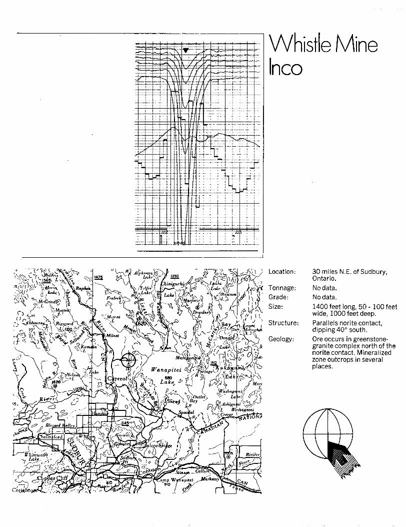
Whistle Mine Inco
) Location: 30 miles N.E. of Sudbury, Ontario.No data. No data.
1400 feet long, 50 -100 feet wide, 1000 feet deep.Parallels norite contact, dipping40 0 south.Ore occurs in greenstone- granite complex north of the norite contact. Mineralized zone outcrops in several places.
1 ~---------- X XYZ EXPORT 1 DATABASE
1f x
Line 10510418.17509126.56508365.30
Line 20509120.41510425.54
Line 30510378.58509133.15509067.49
Line 40509080.87
Line 50510435.20
i — — ——t1 XYZ EXPORT/ DATABASEit11 xx————1Line 40
510251.50Line 50
510451.32Line 80
510284.86Line 100
509146.63Line 150
510502.88
[08/01/02] [E : \ChampBear\ParkinSouth
y
5183043.095183044.525183046.35
5182943.975182941.88
5182847.265182838.105182837.51
5182742.50
5182646.15
[08/01/02]
fid
7383.007441.007474.00
7588.507646.20
7764.107821.907825.00
7962.80
8143.40
[E: \ChampBear\ParkinNorth
y
5186895.77
5186794.95
5186500.53
5186292.36
5185791.94
fid
5974.00
5818.00
5213.00
4760.80
3852.10
.gdb : SUPER]
anomlabel anomchan
"A" 5 . 0"B"C
"A"B
"A"B"C
"A
"A
.gdb : SUPER]
anomlabel
"A
"A
"A
"A
"A
" 1.01.0
" 6.0" 6.0
6.01.0
" 2.0
0.0
2.0
anomchan
1.0
1.0
1.0
1.0
" 1.0
anomz3
11.00.00.0
13.033.0
76.00.00.0
0.0
0.0
anomz3
0.0
0.0
0.0
0.0
0.0
ONTMIO MINISTRY OF NORTHERN DEVELOPMENT AND MINES
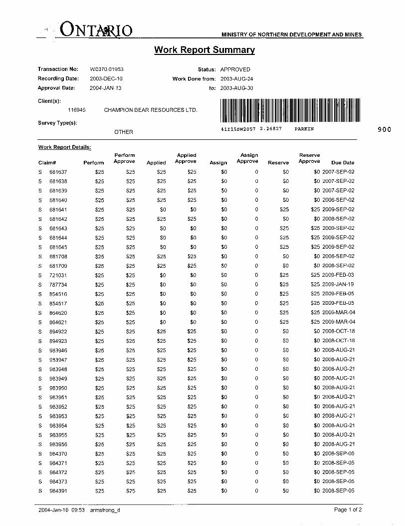
Work Report Summary
Transaction No: W0370.01953 Status: APPROVED
Recording Date: 2003-DEC-10 Work Done from: 2003-AUG-24
Approval Date: 2004-JAN-13 to: 2003-AUG-30
Survey Type(s):^-,-,,,-r, 41I15SW2057 2.26827 PARKIN U l ntK
Work Report Details:
Claim#
S
S
S
S
S
S
S
S
S
S
S
S
S
S
S
S
S
S
S
S
S
S
S
S
S
S
sssssssss
681637
681638
681639
681640
681641
681642
681643
681644
681645
681708
681709
721031
787734
854516
854517
864620
864621
894922
894923
983946
983947
983948
983949
983950
983951
983952
983953
983954
983955
983956
984370
984371
984372
984373
984391
Perform Perform Approve
S25
S25
S25
S25
S25
525
S25
S25
S25
S25
S25
325
525
525
525
525
525
525
525
525
525
525
525
525
525
525
525
525
525
525
525
525
525
525
525
525
525
525
525
525
525
525
525
525
525
525
525
525
525
525
525
525
525
525
525
525
525
525
525
525
525
525
525
525
525
525
525
525
525
525
Applied Applied Approve
525
525
525
525
SO
525
SO
SO
SO
525
525
SO
SO
SO
SO
SO
SO
525
525
525
525
525
525
525
525
525
525
525
525
525
525
525
525
525
525
525
525
525
525
50
525
50
50
50
525
525
50
50
50
50
50
50
525
525
525
525
525
525
525
525
525
525
S25
S25
525
525
525
525
525
525
Assign Reserve Assign Approve Reserve Approve Due Date
SO
SO
soSO
sosoSO
SO
sososoSO
sosososoSO
soSO
soSO
SO
soSO
50
so50
50
SO
soSO
50
50
50
50
0
0
0
0
0
0
0
0
0
0
0
0
0
0
0
0
0
0
0
0
0
0
0
0
0
0
0
0
0
0
0
0
0
0
0
sososoSO
525
SO
525
525
525
SO
so525
525
525
525
525
S25
SO
SO
SO
SO
SO
SO
SO
50
50
50
50
50
50
SO
50
50
50
SO
SO 2007-SEP-02
SO 2007-SEP-02
SO 2007-SEP-02
SO 2006-SEP-02
S25 2009-SEP-02
SO 2008-SEP-02
S25 2009-SEP-02
525 2009-SEP-02
525 2009-SEP-02
SO 2008-SEP-02
SO 2008-SEP-02
S25 2009-FEB-03
525 2009-JAN-19
S25 2009-FEB-05
S25 2009-FEB-05
525 2009-MAR-04
525 2009-MAR-04
SO 2008-OCT-18
50 2008-OCT-18
50 2008-AUG-21
50 2008-AUG-21
50 2008-AUG-21
50 2008-AUG-21
50 2008-AUG-21
50 2008-AUG-21
SO 2008-AUG-21
50 2008-AUG-21
50 2008-AUG-21
50 2008-AUG-21
SO 2008-AUG-21
50 2008-SEP-05
50 2008-SEP-05
SO 2008-SEP-05
50 2008-SEP-05
50 2008-SEP-05
900
2004-Jan-16 09:53 armstrong_d Page 1 of 2
ONTMIO MINISTRY OF NORTHERN DEVELOPMENT AND MINES
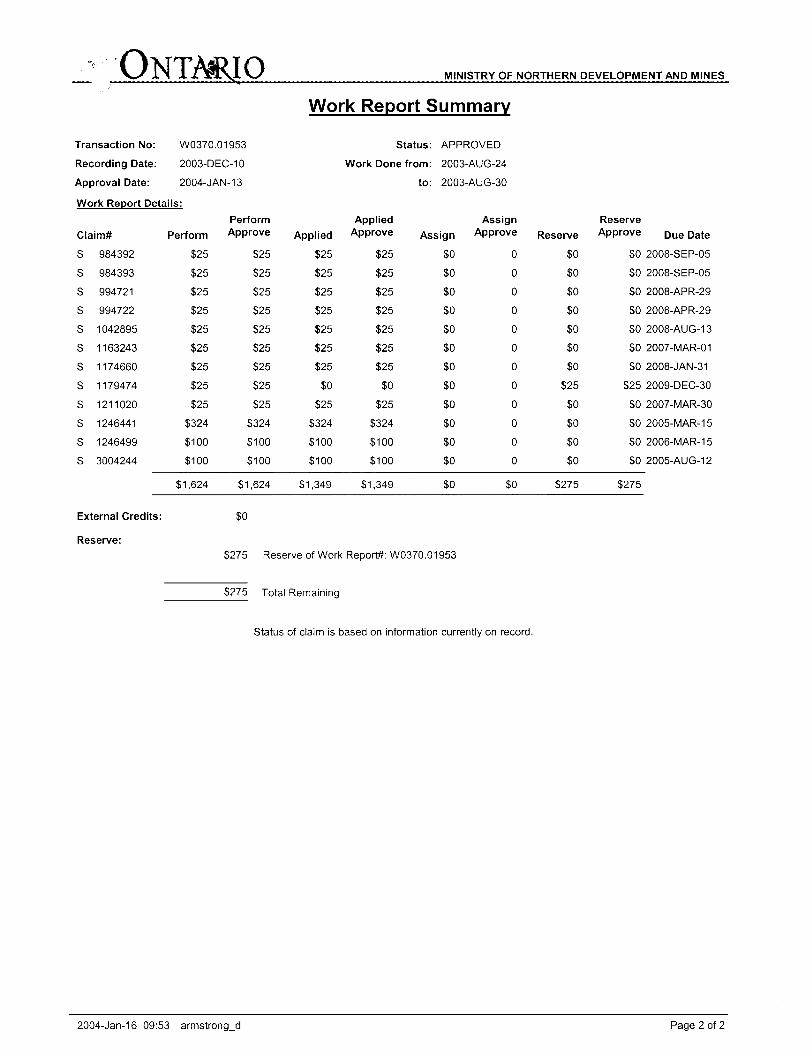
Work Report Summary
Transaction No:
Recording Date:
Approval Date:
W0370.01953
2003-DEC-10
2004-JAN-13
Status: APPROVED
Work Done from: 2003-AUG-24
to: 2003-AUG-30
Work Report Details:
Claim#
S
S
S
S
S
S
S
S
S
S
S
S
984392
984393
994721
994722
1042895
1163243
1174660
1179474
1211020
1246441
1246499
3004244
Perform
S25
S25
S25
S25
S25
S25
S25
S25
S25
S324
S100
S100
31.624
External Credits:
Perform Approve
S25
S25
S25
S25
S25
S25
S25
S25
S25
3324
S100
S100
31,624
SO
Applied
325
325
325
S25
325
325
325
SO
S25
S324
S100
3100
31,349
Applied Approve
S25
S25
S25
325
S25
325
325
SO
S25
S324
S100
3100
31,349
Assign
SO
SO
sosoSO
sososososososo
SO
Assign Approve
0
0
0
0
0
0
0
0
0
0
0
0
so
Reserve
SO
SO
sosoSO
soSO
S25
SO
SO
SO
SO
3275
Reserve Approve
SO
soSO
SO
SO
SO
SO
325
SO
SO
SO
SO
S275
Due Date
2008-SEP-05
2008-SEP-05
2008-APR-29
2008-APR-29
2008-AUG-1 3
2007-MAR-01
2008-JAN-31
2009-DEC-30
2007-MAR-30
2005-MAR-15
2006-MAR-15
2005-AUG-12
Reserve:S275 Reserve of Work
3275 Total Remaining
Report*: W0370.01 953
Status of claim is based on information currently on record.
2004-Jan-16 09:53 armstrong-d Page 2 of 2
Ministry ofNorthern Developmentand Mines
Date:2004-JAN-14
Ministere duDeveloppement du Nord et des Mines Ontario
GEOSCIENCE ASSESSMENT OFFICE 933 RAMSEY LAKE ROAD, 6th FLOOR SUDBURY, ONTARIO P3E6B5
CHAMPION BEAR RESOURCES LTD. 2005-9TH STREET, S..W., CALGARY, ALBERTA T2T 3C4 CANADA
Tel: (888) 415-9845 Fax:(877)670-1555
Dear Sir or Madam
Submission Number: 2.26827 Transaction Number(s): W0370.01953
Subject: Approval of Assessment Work
We have approved your Assessment Work Submission with the above noted Transaction Number(s). The attached Work Report Summary indicates the results of the approval.
At the discretion of the Ministry, the assessment work performed on the mining lands noted in this work report may be subject to inspection and/or investigation at any time.
The revisions outlined in the Notice dated December 19, 2003 have been corrected. Accordingly, assessment work credit has been approved as outlined on the Declaration of Assessment Work Form that accompanied this submission.
If you have any question regarding this correspondence, please contact [email protected] or by phone at (705) 670-5856.
Yours Sincerely,
BRUCE GATES by email at
Ron C. Gashinski
Senior Manager, Mining Lands Section
Cc: Resident Geologist
Champion Bear Resources Ltd. (Claim Holder)
Assessment File Library
Champion Bear Resources Ltd. (Assessment Office)
Joe Hinzer (Agent)
Visit our website at http://www.gov.on.ca/MNDM/LANDS/mlsmnpge.htm Page: 1 Correspondence 10:19036
MINWIHYOF NORTHERN T AND MIWB
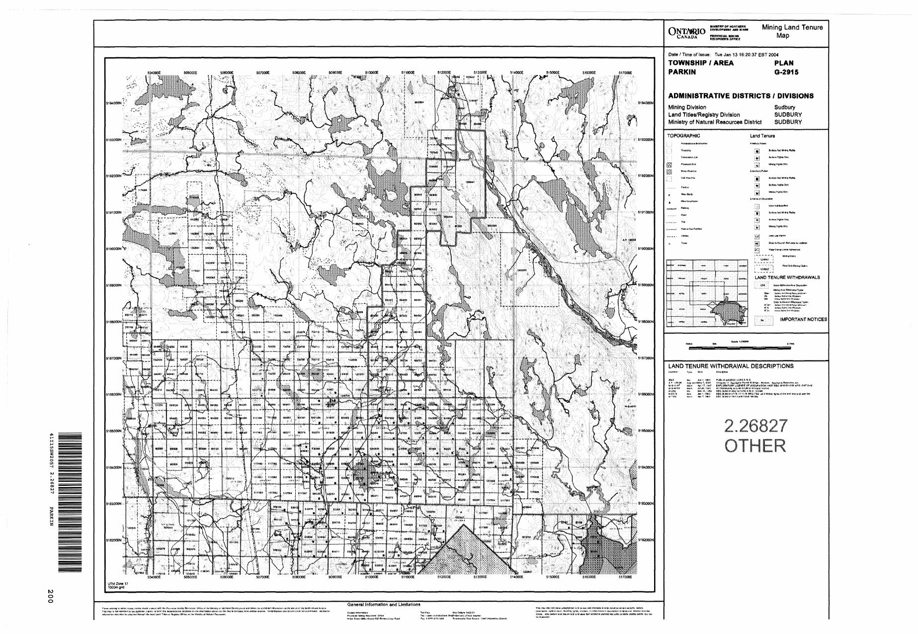
CANADA PROVINCIAL xminoV.AINADA
Mining Land Tenure Map
01enS
HS5
to o o
504000E S06000E soroooe 50BOOOE S09000E 810000E 511000S 51400QE 51500QE S16000E
5164000N S194000N
M810QON
,5'518JOOON
General Information and Limitationstn*Btowi mure ,
lnt fimnn IMtotr ffiritt *.W Bjnwv* l^kK Rmrl
enH-tnEmia. rtfNni wain. Hornito^ rQhit, ir^nsn^, Mntfwdorti^ ni flBpotit^n ol itjnutunn Wffm Cremi, AtwuHUinUndlenuieand HitfuiwtM wnloetot piBWDft Mwanttv l***ato minlnn tl
Date ^ Time of Issue; Tue Jan 13 16:20:37 EST 2004
TOWNSHIP l AREA PLAN PARKIN G-2915
ADMINISTRATIVE DISTRICTS l DIVISIONS
Mining Division SudburyLand Titles/Registry Division SUDBURYMinistry of Natural Resources District SUDBURY
TOPOGRAPHIC land Tenure
f Mure ahatv
I.IJSI li!
EI
LAND TENURE WITHDRAWALS
N, l IMPORTANT NOTICES
LAND TENURE WITHDRAWAL DESCRIPTIONS
5MJ Wa Juoi. IMS PUOUCACiKDS liA P, KB. ffi** 4)s fSHirtWrtj-T, '/OCX* Cills.)iHy (1 AygiugaW.6-1V9T Wtm Apt f, 'W CKPi.CiRATORi' LIC
w, ami ws DEC i4, i tea sEc.x&aiiw.ifB^i.W,UT,78 Wm J*n M WO SSC',*,1)OW,(l*)rS l
.PBirrtt WORSW - (MKttk i.j.jwgBHi PWK^Hl-W AR|Si OP OCCUPATION I498T SEC J(IW-3-1f'BT *PK IT'97 UtM
2.26827 OTHER
Ymmamnhfc rims R™^* l
510000E
5191000N511500E
5191000N
LF
\
Grid North
UTM Zone 17
NAD83
O
O
GF
508000E
5187500N512500E
5187500N
Peak Response Symbo s
o 1 Channee 2 Channee 3 Channe^ 4 Channe^ 5 Channe41 6 Channe
MF
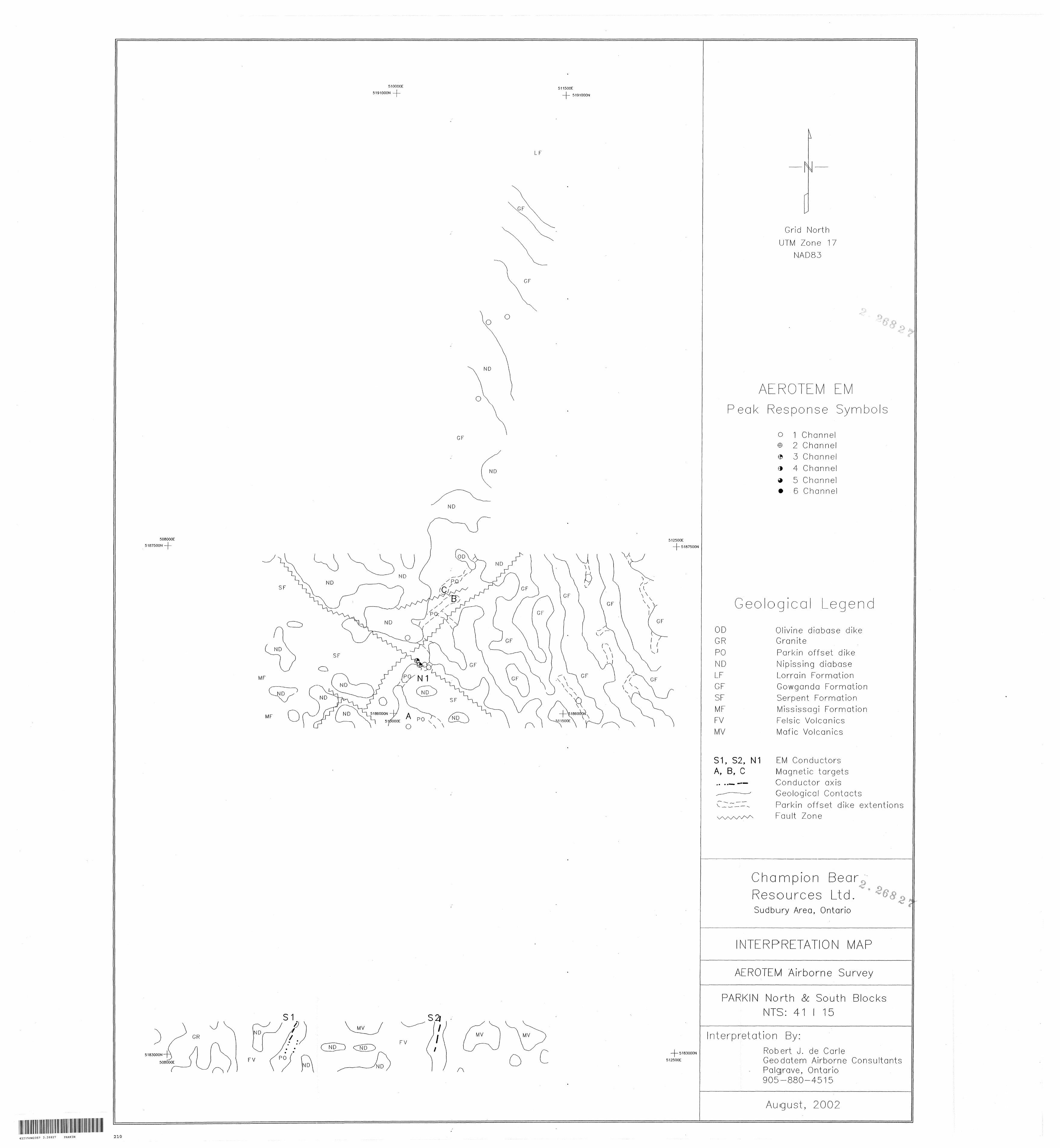
Geo oq'ca Legend-——-rf' -i.i-.i-a-*
ODGRPONDLFGFSFMFFVMV
Olivine diabase dike GraniteParkin offset dike
Nipissing diabase
Lorrain Formation Gowganda Formation
Serpent Formation
Mississagi Formation
Felsic Volcanics
Mafic Volcanics
S1, S2, N1 A, B, C
EM ConductorsMagnetic targetsConductor axisGeological ContactsParkin offset dike extentionsFault Zone
5183000N
508000E
FV
•5183000N
512500E
Champion Bear,,,i ,,;.*"V
Resources Ltd.Sudbury Area, Ontario
NTERPRETATON MAP
AEROTEM Airborne Survey
PARKIN North 8c South Blocks NTS: 41 l 15
interpretation By:
Robert J. de Carle Geodatem Airborne Consultants Palgrave, Ontario 905-880-4515
August, 2002
41I15SW2057 2.26827 PARKIN 210
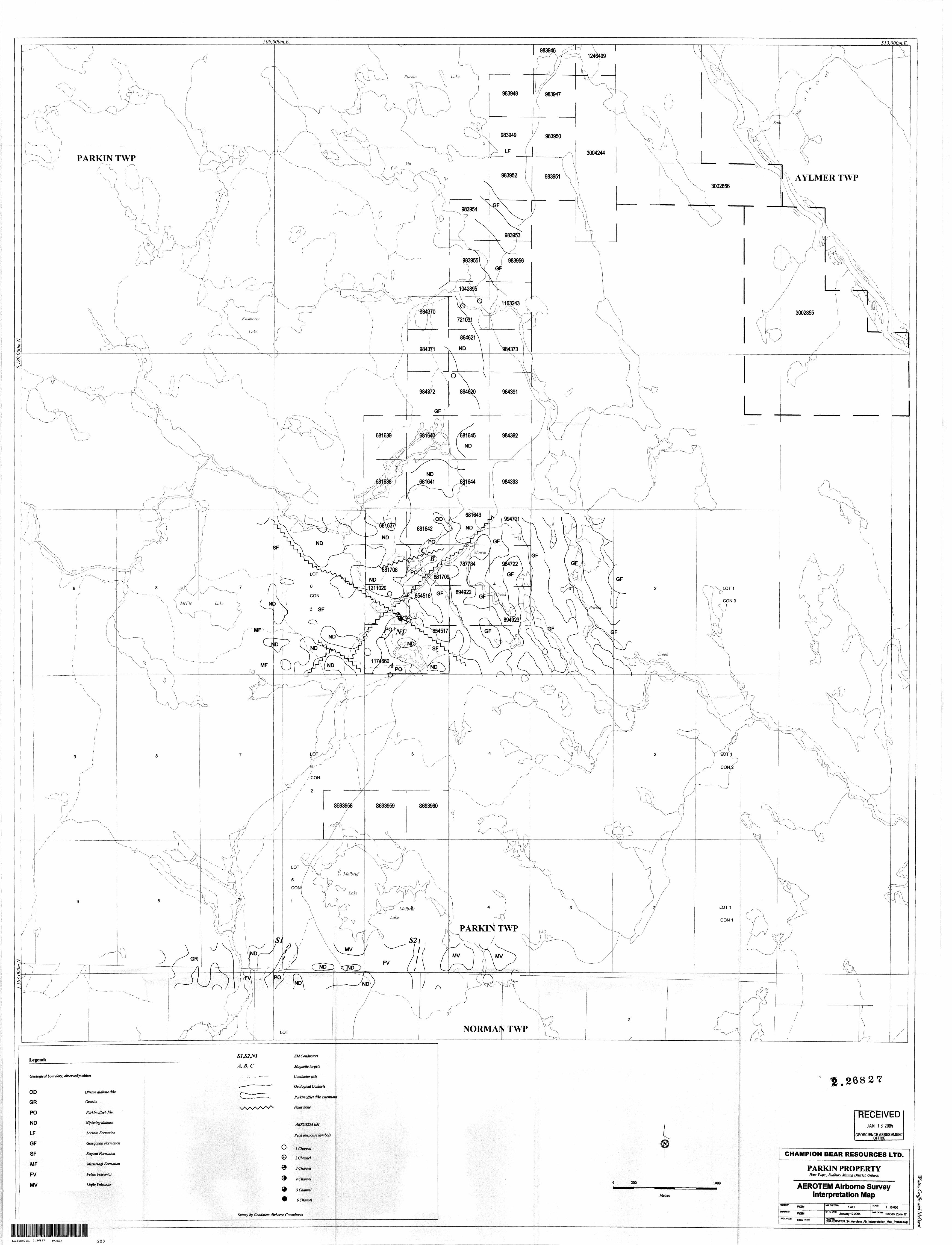
509,OOOm.E. 513.000m.E.
1246499
PARKIN TWP
AYLMER TWP
PARKIN TWP
NORMAN TWP
Legend:A, B, C
Geological boundary, observed/position
OD
GR
PO
ND
LF
GF
SF
MF
FV
MV
Olivine diabase dike
Granite
Parkin offset dike
Nipissing diabase
Lorrain Formation
Gowganda Formation
Serpent Formation
Mssissagi Formation
Felsic Volcanics
Mafic Volcanics
O
e
EMConductors
Magnetic targets
Conductor axis
Geological Contacts \
Parkin offset dike extentioris
Fault Zone
AEROTEMEM fi i
Peak Response Symbols j
1 Channel
2 Channel
3Channel
4 Channel
5 Channel
6 Channel
Survey by Geodatem Airborne Consultants
f .26827
RECEIVEDJAN 1 3 2004
GEOSCIENCE ASSESSMENT OFFICE——-—
200 1000
Metres
CHAMPION BEAR RESOURCES LTD.
PARKIN PROPERTYHart Twps., Sudbury Mining District, Ontario
AEROTEM Airborne Survey Interpretation Map
WORK BY:WGM
DRAWN BY-WGM
pROj.cooe CBAPRN
WP SHEET Not 1of1UP-TOOUTE
January 12,2004FLEMMC:
SCALE'1:10,000
IMP MUM NAD83,Zone17
OBA EXRPRN,34.Aerotem.AirJnterpretation.Map.PaiWn.dwg
iCi
41I15SW2057 2.26827 PARKIN 220


![Multitasking guardian of mitochondrial quality: Parkin …...the autoubiquitination activity of Parkin [41]. Involvement of Parkin in mitochondrial processes As an E3 ligase, Parkin](https://img.pdfslide.us/doc/110x75/60ff3ba3c386cc67f77a5535/multitasking-guardian-of-mitochondrial-quality-parkin-the-autoubiquitination.jpg)