Embed Size (px)
Citation preview

RPSEA CTR 1402
Ultra Deepwater Dry Tree System for Drilling and Production in GOM
Stage 1 Study Report
Document No: 08110-H-RE10-GE-0001 Rev. C
June 19, 2009 FloaTEC Project # 08110
NOTICE The material contained in the attached document(s) is confidential. The information
contained herein may be used only by the intended recipient(s) and only for the intended purpose. Unauthorized use or distribution of the information contained in
this document(s) is prohibited.

RPSEA CTR 1402 Ultra Deepwater Dry Tree System for
Drilling and Production in GOM Stage 1 Study Report
08110-H-RE10-GE-0001 REV C
© 2009 FLOATEC, LLC ALL RIGHTS RESERVED
2
TABLE OF CONTENTS
1.0 INTRODUCTION...............................................................................................................3 1.1 Objectives of Study........................................................................................................ 3 1.2 The Description of DTS Concepts ................................................................................ 3 2.0 SCOPE OF WORK ...........................................................................................................6
3.0 DESIGN BASIS.................................................................................................................8
4.0 STUDY RESULTS ..........................................................................................................12 4.1 Topside Layout, Wind and Payload Estimates.......................................................... 12 4.1.1 Topside Layout ...................................................................................................................... 12 4.1.2 WINDOS Model of Wind Load............................................................................................... 15 4.1.3 Payload.................................................................................................................................. 18 4.2 Hull Sizing ..................................................................................................................... 20 4.3 Production TTR Sizing and Analysis.......................................................................... 25 4.3.1 Riser Layout and General Configuration............................................................................... 25 4.3.2 Riser Sizing, Weight, and Tension Properties....................................................................... 30 4.3.3 Riser Tension Design and Stroke Analysis ........................................................................... 31 4.3.4 Riser Strength Analysis ......................................................................................................... 33 4.4 Production Riser Tensioner ........................................................................................ 37 4.5 Mooring Analysis ......................................................................................................... 38 4.5.1 T-Semi Mooring Configuration .............................................................................................. 38 4.5.2 E-Semi Base Case Mooring Configuration ........................................................................... 40 4.6 Global Performance Analysis ..................................................................................... 43 4.6.1 Quayside Stability.................................................................................................................. 44 4.6.2 Tow-out Stability .................................................................................................................... 45 4.6.3 In-place Stability .................................................................................................................... 45 4.6.4 In-place Fully-Coupled Model................................................................................................ 46 4.6.5 In-place Environmental Mean Load....................................................................................... 51 4.6.6 Frequency Domain Analysis.................................................................................................. 51 4.6.7 Time Domain Analysis........................................................................................................... 51 4.7 Hull Weights.................................................................................................................. 57 4.8 Constructability ............................................................................................................ 58 4.8.1 T-Semi : Hull and Truss Construction Installation ................................................................. 58 4.8.2 E-Semi : Hull Construction & Installation .............................................................................. 67 4.9 Preliminary Project Execution Plan and Schedule ................................................... 82 4.9.1 Introduction............................................................................................................................ 82 4.9.2 Preliminary Schedule ............................................................................................................ 84 5.0 CONCLUSIONS AND RECOMMENDATIONS ..............................................................85
RPSEA CTR 1402 Ultra Deepwater Dry Tree System for
Drilling and Production in GOM Stage 1 Study Report
08110-H-RE10-GE-0001 REV C
© 2009 FLOATEC, LLC ALL RIGHTS RESERVED
3
1.0 INTRODUCTION
1.1 Objectives of Study
RPSEA had provided an opportunity to develop a dry tree semisubmersible (DTS) that can be cost competitive with the Spar through their program CTR 1402 for “Ultra-Deepwater Dry Tree System for Drilling and Production in the Gulf of Mexico, Phase 1”. The main objectives of the project are to assess alternative dry tree semisubmersible concept designs for two different payload cases in accordance with the agreed basis of design, and select one hull form option for model testing and further development in Phase 2 of the RPSEA program. The intent is to investigate the feasibility of developing these platform designs and to identify any technical limits to areas where further qualification or testing will be required in the industry. The project is divided into Stages with distinct work scopes. In Stage 1, the initial task is to jointly develop the basis of design for the project, followed by a sizing exercise to enable comparison of all dry tree platform and riser options selected for study. A comparative assessment of the results of this task will be presented and evaluated at a workshop. The outcome of the workshop will be the selection of two dry tree hulls and associated riser forms for further evaluation and refinement. In Stage 2, the two options selected for further study will be developed to the extent necessary to ensure their feasibility in all areas, and provide sufficient detail to develop +/-30% cost estimates. A second workshop will be held to select one case to be model tested. In Stage 3, model testing will be performed at a reputable, experienced facility. All results of these tasks will be assembled into a final report, and agreement will be reached on an appropriate method to transfer technology to industry.
This report summarizes the results of the work activities for the Stage 1 of the project.
1.2 The Description of DTS Concepts
FloaTEC conducted the study of two dry tree semisubmersible design concepts as described below: T- Semi and E-Semi The Truss Semi (T-Semi) and the ESEMI II (E-Semi) are two versions of a dry-tree semisubmersible concept that uses heave plate(s) to improve the motion

RPSEA CTR 1402 Ultra Deepwater Dry Tree System for
Drilling and Production in GOM Stage 1 Study Report
08110-H-RE10-GE-0001 REV C
© 2009 FLOATEC, LLC ALL RIGHTS RESERVED
4
characteristics by avoiding resonant behavior in the peak of the wave spectrum as top-tensioned risers are added. Therefore these heave-plated DTS offer the motions of a Spar and the functionality of a conventional semisubmersible. Figure 1.2-1 shows the T-Semi and Figure 1.2-2 shows the E-Semi. These heave-plated dry tree semis have similar design philosophies, featuring a semi-submersible hull and one or more heave plates supported beneath the hull by means of a truss or extendable columns. The heave plates offer the benefit of allowing the heave natural period to be tuned such that, when top tensioned risers are added, the resulting natural period is above the wave energy peak period. Furthermore, the heave responses in the peak region of the wave spectrum are minimized. Besides the heave response characteristics, the hull designs in the two concepts provide typical advantages of the semi such as quay-side integration and commissioning of topsides, better topside deck layout, tow-out to site in a vertical position, and so on. The main difference between the two design versions, however, is the installation method as described in Section 4.8. The preliminary model test for the T-Semi was done in December 2006, with further tests with latest GOM environment conditions, completed in late 2008. The model tests for the E-Semi was first done in the July of 2004, and was re-tested with latest GOM environment in the first quarter of 2008.
Numerical analysis for both the designs show that they have heave motions similar to that of a Spar, and are well suited for supporting top tensioned riser systems. The dry tree semi-submersible designs have been under development in FloaTEC, through its parent companies, for over 5 years now. The various model tests done have shown good correlation with the analytical tools, and the data points were used to design the DTS hulls based on the RPSEA Stage 1 requirements.

RPSEA CTR 1402 Ultra Deepwater Dry Tree System for
Drilling and Production in GOM Stage 1 Study Report
08110-H-RE10-GE-0001 REV C
© 2009 FLOATEC, LLC ALL RIGHTS RESERVED
5
Figure 1.2-1 T-Semi

RPSEA CTR 1402 Ultra Deepwater Dry Tree System for
Drilling and Production in GOM Stage 1 Study Report
08110-H-RE10-GE-0001 REV C
© 2009 FLOATEC, LLC ALL RIGHTS RESERVED
6
Figure 1.2-2 E-Semi 2.0 SCOPE OF WORK
The project is divided into Stages with distinct work scopes. In Stage 1, the initial task is to jointly develop the basis of design for the project, followed by a sizing exercise to enable comparison of all dry tree platform and riser options selected for study. A comparative assessment of the results of this task will be presented and evaluated at a workshop. The outcome of the workshop will be the selection of two dry tree hulls and associated riser forms for further evaluation and refinement.

RPSEA CTR 1402 Ultra Deepwater Dry Tree System for
Drilling and Production in GOM Stage 1 Study Report
08110-H-RE10-GE-0001 REV C
© 2009 FLOATEC, LLC ALL RIGHTS RESERVED
7
The scope of work is described in details in the Statement of Work included in Appendix 1 of the study contract.

RPSEA CTR 1402 Ultra Deepwater Dry Tree System for
Drilling and Production in GOM Stage 1 Study Report
08110-H-RE10-GE-0001 REV C
© 2009 FLOATEC, LLC ALL RIGHTS RESERVED
8
3.0 DESIGN BASIS
The semisubmersibles are to be designed for drilling and production in 8,000 feet waters in the central region of the Golf of Mexico. The platform design life is 20 years. Two sets of functional requirements were specified by RPSEA as follows:
Base Case
Sensitivity Case
Oil Process production rate (KBD) 100 75
Max. produced water rate (KBD) 40 30
Max total fluid processing rate (KBD) 120 90
Peak gas processing rate (MCFD) 50 38
Production TTRs 12 9
A number of steel catenary risers are also specified as shown in the field layouts below:

RPSEA CTR 1402 Ultra Deepwater Dry Tree System for
Drilling and Production in GOM Stage 1 Study Report
08110-H-RE10-GE-0001 REV C
© 2009 FLOATEC, LLC ALL RIGHTS RESERVED
9
Field Layout for Base Case

RPSEA CTR 1402 Ultra Deepwater Dry Tree System for
Drilling and Production in GOM Stage 1 Study Report
08110-H-RE10-GE-0001 REV C
© 2009 FLOATEC, LLC ALL RIGHTS RESERVED
10
Field Layout for Sensitivity Case

RPSEA CTR 1402 Ultra Deepwater Dry Tree System for
Drilling and Production in GOM Stage 1 Study Report
08110-H-RE10-GE-0001 REV C
© 2009 FLOATEC, LLC ALL RIGHTS RESERVED
11
The semisubmersibles shall be designed to meet the global response criteria:
Response Conditions with Safety Criteria B
Conditions with Safety Criteria A
Semisubmersible In Place Combined Pitch & Roll (single amplitude)
10 degrees (intact) 4 degrees (intact)
Horizontal Acceleration (at top deck, single amplitude)
0.35 g 0.15 g
Max. Offset – Intact 5% of water depth Max. Offset – Damaged 7% of water depth Minimum Air gap 5 ft
Details of the functional requirements and design conditions are described in the FloaTEC Design Premise Document # 08110-G-RE-GE-0001 issued on March 9, 2009.

RPSEA CTR 1402 Ultra Deepwater Dry Tree System for
Drilling and Production in GOM Stage 1 Study Report
08110-H-RE10-GE-0001 REV C
© 2009 FLOATEC, LLC ALL RIGHTS RESERVED
12
4.0 STUDY RESULTS
4.1 Topside Layout, Wind and Payload Estimates
4.1.1 Topside Layout
Topside layout, equipment sizes, and weights are based on GOM data given in design basis. Since the GOM model was founded on a Spar hull and has a 3 level deck design, some modification needs to be made for the accommodation of a semisubmersible hull. Thus, a 2 level deck design (drilling deck@125ft and production deck@75ft elevation) was employed and the weights of drilling rig, ROV, riser tensioners, fluid storage and deck steel has been reconciled. In Figure 4.1-1 to 4.1-3, the overall configurations of topside layout are provided. The weight of topside equipments including drilling rig in operating condition were scaled from the dry weight by 140% and the dry weight includes 25% contingency. Summarized payload is given in Table 4.1-1.
For the global performance and stability analysis, the center of gravity coordinates and the radius of gyration for topside were estimated and given in Table 4.1-2. It should be noted that this estimation excludes the weight of drilling fluid, dead oil storage, deck structure, hull, mooring, SCR and TTR. For the estimation of system value, all other structural element should be added. The vertical coordinate of the center of gravity of the topside equipment was assumed to be 3 ft above the base of the equipment. The horizontal coordinates were assumed to be at the geometric center of the equipment.
Table 4.1-1 Payload Summary(operating condition)
Item (st) Unit Base Case Payload Facilities (st) 7,167
Drilling, including rig (st) 7,000 Deck area including wellbay
area per level (ft×ft) 240×240
*Total payload excludes deck steel weight.
Table 4.1-2 Center of Gravity and Radius of Gyration Coordinates of Center of
Gravity(CG) Radius of Gyration
X Y Z Rx Ry Rz
(ft) (ft) (ft) (ft) (ft) (ft)
-3.18 -7.30 103.50 120.76 117.54 47.22

RPSEA CTR 1402 Ultra Deepwater Dry Tree System for
Drilling and Production in GOM Stage 1 Study Report
08110-H-RE10-GE-0001 REV C
© 2009 FLOATEC, LLC ALL RIGHTS RESERVED
13
Figure 4.1-1 Drilling Deck Layout

RPSEA CTR 1402 Ultra Deepwater Dry Tree System for
Drilling and Production in GOM Stage 1 Study Report
08110-H-RE10-GE-0001 REV C
© 2009 FLOATEC, LLC ALL RIGHTS RESERVED
14
Figure 4.1-2 Production Deck Layout

RPSEA CTR 1402 Ultra Deepwater Dry Tree System for
Drilling and Production in GOM Stage 1 Study Report
08110-H-RE10-GE-0001 REV C
© 2009 FLOATEC, LLC ALL RIGHTS RESERVED
15
Figure 4.1-3 3D View of Topside
4.1.2 WINDOS Model of Wind Load
Prior to the physical wind tunnel tests, numerical WINDOS models had been built up to calculate the wind forces and moments. WINDOS is a computer program for the calculation of wind loads on offshore structures. The program was developed to bridge the gap between the two common methods used for wind load prediction: the simple calculation models provided by the classification societies and the model testing in a wind tunnel. The program can handle arbitrary types of offshore structures.
The computational approach is based on the building block approach. The structure is composed of a number of standard components including rectangular prisms, cylinders, lattice structures, ship hulls, helicopter decks and user defined components. Theoretical and empirical relations are used to calculate interactions (shielding) between components and lift forces on elevated and tilted

RPSEA CTR 1402 Ultra Deepwater Dry Tree System for
Drilling and Production in GOM Stage 1 Study Report
08110-H-RE10-GE-0001 REV C
© 2009 FLOATEC, LLC ALL RIGHTS RESERVED
16
decks. The program is able to compute drag, lift and overturning moment on arbitrary structures in various tilted conditions. WINDOS allows a quick and easy assessment of wind loads on arbitrary offshore structures. The structure types include semi-submersibles, TLPs, jack-up rigs, jackets, fixed structures and ships. The accuracy is sufficient for use in the preliminary design Stage.
The WINDOS model for base case is illustrated in the Figures 4.1-4.
Figure 4.1-4 Isometric View – Looking North West

RPSEA CTR 1402 Ultra Deepwater Dry Tree System for
Drilling and Production in GOM Stage 1 Study Report
08110-H-RE10-GE-0001 REV C
© 2009 FLOATEC, LLC ALL RIGHTS RESERVED
17
The wind forces and moments as function of headings for T-Semi are illustrated in the Figures 4.1-7 and 4.1-8. The wind forces and moments as function of headings for E-SEMI are illustrated in the Figures 4.1-9 and 4.1-10. For sensitivity case, wind force and moments are scaled according to topside weight.
-0.080
-0.060
-0.040
-0.020
0.000
0.020
0.040
0.060
0.080
0 45 90 135 180 225 270 315 360
Heading (deg)
Forc
e C
oeffi
cien
t (ki
ps/(f
t/s)^
2
CFXCFYCF total
Figure 4.1-7 T-Semi Wind Forces Coefficients
-8.000
-6.000
-4.000
-2.000
0.000
2.000
4.000
6.000
8.000
10.000
0 45 90 135 180 225 270 315 360
Heading (deg)
Mom
ent C
oeffi
cien
t (ki
ps.ft
/(ft/s
)^2
CMXCMYCM total
Figure 4.1-8 T-Semi Wind Moments Coefficients

RPSEA CTR 1402 Ultra Deepwater Dry Tree System for
Drilling and Production in GOM Stage 1 Study Report
08110-H-RE10-GE-0001 REV C
© 2009 FLOATEC, LLC ALL RIGHTS RESERVED
18
-0.080
-0.060
-0.040
-0.020
0.000
0.020
0.040
0.060
0.080
0 45 90 135 180 225 270 315 360
Heading (deg)
Forc
e C
oeffi
cien
t (ki
ps/(f
t/s)^
2
CFXCFYCF total
Figure 4.1-9 E-Semi Wind Forces Coefficients
-8.000
-6.000
-4.000
-2.000
0.000
2.000
4.000
6.000
8.000
10.000
0 45 90 135 180 225 270 315 360
Heading (deg)
Mom
ent C
oeffi
cien
t (ki
ps.ft
/(ft/s
)^2
CMXCMYCM total
Figure 4.1-10 E-Semi Wind Moments Coefficients
4.1.3 Payload
Table 4.1-5 shows the payload of the base case which FloaTEC estimated, and it is compared with the design basis given by RPSEA. All the loads are kept the
RPSEA CTR 1402 Ultra Deepwater Dry Tree System for
Drilling and Production in GOM Stage 1 Study Report
08110-H-RE10-GE-0001 REV C
© 2009 FLOATEC, LLC ALL RIGHTS RESERVED
19
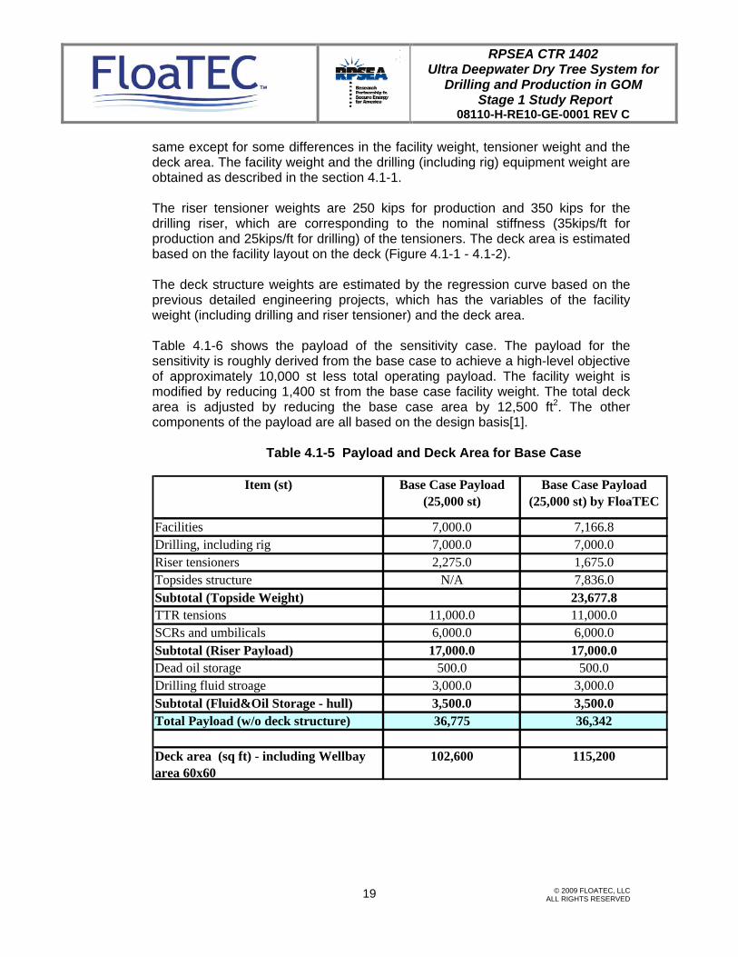
same except for some differences in the facility weight, tensioner weight and the deck area. The facility weight and the drilling (including rig) equipment weight are obtained as described in the section 4.1-1. The riser tensioner weights are 250 kips for production and 350 kips for the drilling riser, which are corresponding to the nominal stiffness (35kips/ft for production and 25kips/ft for drilling) of the tensioners. The deck area is estimated based on the facility layout on the deck (Figure 4.1-1 - 4.1-2). The deck structure weights are estimated by the regression curve based on the previous detailed engineering projects, which has the variables of the facility weight (including drilling and riser tensioner) and the deck area. Table 4.1-6 shows the payload of the sensitivity case. The payload for the sensitivity is roughly derived from the base case to achieve a high-level objective of approximately 10,000 st less total operating payload. The facility weight is modified by reducing 1,400 st from the base case facility weight. The total deck area is adjusted by reducing the base case area by 12,500 ft2. The other components of the payload are all based on the design basis[1].
Table 4.1-5 Payload and Deck Area for Base Case
Item (st) Base Case Payload (25,000 st)
Base Case Payload (25,000 st) by FloaTEC
Facilities 7,000.0 7,166.8Drilling, including rig 7,000.0 7,000.0Riser tensioners 2,275.0 1,675.0Topsides structure N/A 7,836.0Subtotal (Topside Weight) 23,677.8TTR tensions 11,000.0 11,000.0SCRs and umbilicals 6,000.0 6,000.0Subtotal (Riser Payload) 17,000.0 17,000.0Dead oil storage 500.0 500.0Drilling fluid stroage 3,000.0 3,000.0Subtotal (Fluid&Oil Storage - hull) 3,500.0 3,500.0Total Payload (w/o deck structure) 36,775 36,342
Deck area (sq ft) - including Wellbay area 60x60
102,600 115,200

RPSEA CTR 1402 Ultra Deepwater Dry Tree System for
Drilling and Production in GOM Stage 1 Study Report
08110-H-RE10-GE-0001 REV C
© 2009 FLOATEC, LLC ALL RIGHTS RESERVED
20
Table 4.1-6 Payload and Deck Area for the Sensitivity Case
Item (st) Sensitivity Case Payload (20,000 st)
Sensitivity Case Payload (20,000 st) by FloaTEC
Facilities 5,600.0 5,766.8Drilling, including rig 5,600.0 5,600.0Riser tensioners 1,760.0 1,300.0Topsides structure N/A 6,333.4Subtotal (Topside Weight) 19,000.2TTR tensions 8,372.0 8,372.0SCRs and umbilicals 3,600.0 3,600.0Subtotal (Riser Payload) 11,972.0 11,972.0Dead oil storage 400.0 400.0Drilling fluid stroage 2,400.0 2,400.0Subtotal (Fluid&Oil Storage - hull) 2,800.0 2,800.0Total Payload (w/o deck structure) 27,732 27,439
Deck area (sq ft) - including Wellbay area 60x45
90,100 90,100
4.2 Hull Sizing
The primary requirements for hull sizing are:
• Hydrostatic equilibrium, i.e., buoyancy must be equal to the sum of the total weight and the total vertical loads.
• The pitch/roll restoring force must be sufficient to meet the pitch/roll requirements in the design sea conditions.
• The heave response must not exceed design limit in design sea states. • Sufficient variable ballast capacity must be provided for load and weight
eccentricities (built-in, operational, and accidental events) and other future riser loads.
• There must be sufficient air gap between the lowest point of deck and wave crests.
• Maximum offset must be within the design criteria in extreme sea states for both intact and damaged mooring conditions.

RPSEA CTR 1402 Ultra Deepwater Dry Tree System for
Drilling and Production in GOM Stage 1 Study Report
08110-H-RE10-GE-0001 REV C
© 2009 FLOATEC, LLC ALL RIGHTS RESERVED
21
The other parameters to be considered are:
• Variable Ballast
A semisubmersible hull is designed to operate at the maximum loading condition, but the load of hull will not be always at its maximum. Since the topside load varies depending on the operating conditions, the hull draft changes accordingly. The primary role of variable ballast is to keep the draft constant by controlling the ballast capacity inside of ballast tank in the case of top side load change. Besides keeping the semisubmersible draft constant, the variable ballast has other functions as follows;
T-SemiE-Semi
33.2
8 ft
Figure 4.2-1 Quayside Integration of T-Semi and E-Semi Topside

RPSEA CTR 1402 Ultra Deepwater Dry Tree System for
Drilling and Production in GOM Stage 1 Study Report
08110-H-RE10-GE-0001 REV C
© 2009 FLOATEC, LLC ALL RIGHTS RESERVED
22
(1) To recover the freeboard and even keel position in case of damage. (2) To reserve the buoyancy for future topside load growth and/or future
SCR load. (3) To keep the static heel angle within the allowable range when
overturning moment occurs due to eccentric forces which are mostly caused by the topside eccentricity, unbalanced flow lines load, flooding by damage, and eccentric riser loads. In the present design procedure, it is assumed that the hull damage and the worst eccentric loading do not occur at the same time. The amount of variable ballast required by load eccentricity and future load, if any, is normally greater than that required by the damage condition.
The quayside draft is 29 ft based on the water depth (33.28 ft) of the yard considered for the study. The configuration at the quayside for the top side installation is shown in Figure 4.2-1. The resultant size of the T-Semi and E-Semi are shown in Table 4.2-1 and 4.2-2 for the base and the sensitivity case, respectively. The column and the pontoon size for the sensitivity case is smaller than the base case because the lower payload. Figure 4.2-2 and 4.2-3 show the In-place configuration of the T-Semi and E-Semi for the base case and the sensitivity case.
Table 4.2-1 Principal Dimension of Semi Hulls for the Base Case
Dimensions T-Semi E-Semi
Hull Draft (ft) 81 115Total Draft (ft) 456 275
Column Size (ftxft) 64x64 67x67Column Spacing (ftxft) 196x196 184x184
Pontoon Size (w x h) (ftxft) 31x42 37x25Freeboard (ft) 70 70
Heave Plate Size (ftxft) 147x205 251x251Tow-out Draft (ft) 40 29

RPSEA CTR 1402 Ultra Deepwater Dry Tree System for
Drilling and Production in GOM Stage 1 Study Report
08110-H-RE10-GE-0001 REV C
© 2009 FLOATEC, LLC ALL RIGHTS RESERVED
23
Table 4.2-2 Principal Dimension of Semi Hulls for the Sensitivity Case
Dimensions T-Semi E-Semi
Hull Draft (ft) 74 115Total Draft (ft) 444 265
Column Size (ftxft) 59x59 61x61Column Spacing (ftxft) 187x187 184x184
Pontoon Size (w x h) (ftxft) 25x42 29x25Freeboard (ft) 70 70
Heave Plate Size (ftxft) 143x192 245x245Tow-out Draft (ft) 29-40 29
90 ft
276
ft
81 ft
275
ft 115
ft
90 ft
276
ft
81 ft
275
ft 115
ft
90 ft
276
ft
81 ft
90 ft
276
ft
81 ft
275
ft 115
ft
275
ft 115
ft
Figure 4.2-2 In-place Draft and Heave Plate Location of T-Semi and E-Semi for Base Case

RPSEA CTR 1402 Ultra Deepwater Dry Tree System for
Drilling and Production in GOM Stage 1 Study Report
08110-H-RE10-GE-0001 REV C
© 2009 FLOATEC, LLC ALL RIGHTS RESERVED
24
100
ft24
4 ft
74 ft
100
ft24
4 ft
74 ft
265
ft 115
ft
265
ft 115
ft
Figure 4.2-3 In-place Draft and Heave Plate Location of T-Semi and E-Semi for Sensitivity Case

RPSEA CTR 1402 Ultra Deepwater Dry Tree System for
Drilling and Production in GOM Stage 1 Study Report
08110-H-RE10-GE-0001 REV C
© 2009 FLOATEC, LLC ALL RIGHTS RESERVED
25
4.3 Production TTR Sizing and Analysis
This section provides a summary on the Production TTR general configuration, layout, and preliminary design. It also summarizes on the results of tensioner stroke analysis and strength analysis. Drilling TTR and SCRs are not covered in the scope of this work.
4.3.1 Riser Layout and General Configuration
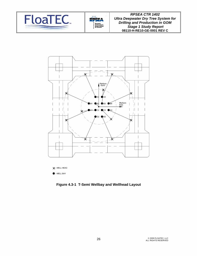
The wellbay and wellhead layout for T-Semi is shown in Figure 4.3-1. That for the E-Semi is shown in Figure 4.3-2. In this study, a total of 11 production TTRs and one drilling TTR are assumed. The wellheads are arranged into two concentric circles. The drilling riser is sitting at the center on a stump. The minimum clearance between any two wellheads is 40 feet. The wellbay spacing is 15 feet between adjacent riser slots. The configurations of the production TTR for T-Semi and E-Semi are shown in Figure 4.3-3 and Figure 4.3-4.
RPSEA CTR 1402 Ultra Deepwater Dry Tree System for
Drilling and Production in GOM Stage 1 Study Report
08110-H-RE10-GE-0001 REV C
© 2009 FLOATEC, LLC ALL RIGHTS RESERVED
26
Figure 4.3-1 T-Semi Wellbay and Wellhead Layout

RPSEA CTR 1402 Ultra Deepwater Dry Tree System for
Drilling and Production in GOM Stage 1 Study Report
08110-H-RE10-GE-0001 REV C
© 2009 FLOATEC, LLC ALL RIGHTS RESERVED
27
Figure 4.3-2 E-Semi Wellbay and Wellhead Layout

RPSEA CTR 1402 Ultra Deepwater Dry Tree System for
Drilling and Production in GOM Stage 1 Study Report
08110-H-RE10-GE-0001 REV C
© 2009 FLOATEC, LLC ALL RIGHTS RESERVED
28
Figure 4.3-3 Production TTR General Configuration for T-Semi

RPSEA CTR 1402 Ultra Deepwater Dry Tree System for
Drilling and Production in GOM Stage 1 Study Report
08110-H-RE10-GE-0001 REV C
© 2009 FLOATEC, LLC ALL RIGHTS RESERVED
29
Figure 4.3-4 Production TTR General Configuration for E-Semi

RPSEA CTR 1402 Ultra Deepwater Dry Tree System for
Drilling and Production in GOM Stage 1 Study Report
08110-H-RE10-GE-0001 REV C
© 2009 FLOATEC, LLC ALL RIGHTS RESERVED
30
4.3.2 Riser Sizing, Weight, and Tension Properties
Riser sizing is based on API RP 1111 requirements on pipe burst and collapse capacities. It is assumed that the material is a high strength steel with a minimum yield strength of 125ksi. The maximum pressure on top of riser is 9,000 psi during pressure test. The designed riser pipe sizes are shown in Table 4.3-1. A wall thickness mill tolerance of +/-10%, and a corrosion allowance of 1/8” is considered. With information provided in the Design Basis on the drilling TTR, the SCRs, and the umbilicals, riser payload can be calculated. They are summarized in Table 4.3-2.
Table 4.3-1 Production TTR Sizing
Unit in inch Outer Riser Inner Riser TubingOD 13.813 10.750 5.500ID 12.463 9.700 4.122
WT 0.675 0.525 0.689
Table 4.3-2
No. of Risers
Vert Load (kips)
TTR - Production 1,809 11 19,899TTR - Drilling 2,000 1 2,000
TTR Vertical Load 21,899SCR - Satellite Well Tieback (SCR) 620 6 3,720SCR - Water Injection 980 2 1,960SCR - Oil Export 1,820 2 3,640SCR - Gas Export 1,060 1 1,060Umbilical 240 6 1,440
SCR Vertical Load 11,820Total Riser Vert Loads 33,719
TTR Tensioner Wt 5) EachTTR - Production 250 11 2,750TTR - Drilling 250 1 250
Total Riser Equipment Wt 3,000
1) SCR vertical load defined at riser porch TTR vertical load at riser tensioner ring including Tree weight and BOP weight when applicable, excluding tensioner weight.2) All payload estimate include a 5% conti. on steel. 3) Vertical payload estimate of TTRs do not include tensioner weight4) Vessel at Nominal Position5) Tensioner weight estimate includes support structures
RPSEA Riser Payload - Base Case
Max + Future Risers 12_TTR + 11_SCR +
6_UmbRiser/Umbilical Name
Vertical Loads at top Connector
(kips) 1)

RPSEA CTR 1402 Ultra Deepwater Dry Tree System for
Drilling and Production in GOM Stage 1 Study Report
08110-H-RE10-GE-0001 REV C
© 2009 FLOATEC, LLC ALL RIGHTS RESERVED
31
4.3.3 Riser Tension Design and Stroke Analysis
It is assume that riser top tension is provided by hydro-pneumatic tensioners. Tensioner stiffness design is based on an assumed tension curve and riser tension requirements under extreme stroke conditions. In this study, TTR top tension factor is set to 1.3 according to Design Basis requirements. The nominal tensioner stiffness is 25 kips/ft. Tensioner stroke analysis has been conducted for both T-Semi and E-Semi. Major contributions to riser stroke includes:
• Vessel offset and TTR splay, including splay induced upstroke and down
stroke • Vessel heave and heel motions (including the effect of off-centered TTRs) • Tidal effects and storm surges • One compartment flooded condition
Stroke analyses due to vessel motions are performed using time-domain global performance simulations. Results of the analysis are also plotted in Figure 4.3- 5. It can be seen that maximum stroke range remains under the allowable stroke range of 25 feet set forth in the Design Basis.

RPSEA CTR 1402 Ultra Deepwater Dry Tree System for
Drilling and Production in GOM Stage 1 Study Report
08110-H-RE10-GE-0001 REV C
© 2009 FLOATEC, LLC ALL RIGHTS RESERVED
32
-20
-15
-10
-5
0
5
10
15
20
25
30
100 -YearIntact
100 - YearDamaged
100 -YearIntact
100 -YearDamaged
Total StrokeRange
Stro
ke (f
t)
T-SemiE-Semi
Figure 4.3-5 Production TTR Stroke Analysis Results

RPSEA CTR 1402 Ultra Deepwater Dry Tree System for
Drilling and Production in GOM Stage 1 Study Report
08110-H-RE10-GE-0001 REV C
© 2009 FLOATEC, LLC ALL RIGHTS RESERVED
33
4.3.4 Riser Strength Analysis
Riser dynamic responses and stress analysis have been performed in time domain for critical load cases. Base case vessel configurations are investigated in this study. Sensitivity cases are not covered as the vessel performance under these cases appears to be not too far from the bases cases. Stress analysis is performed against 3 load conditions. They are the Operational, Extreme, and Survival Conditions. The tapered stress joint at riser bottom, and the riser keel joint with double tapers are critical components with respect to stresses. A preliminary design of these components is conducted for this study. It is assume that the stress joint taper is 30 feet long, the keel joint taper is also 30 feet long. The FE analysis model is constructed in ABAQUS. The dual casing riser is modeled by a composite riser casing, with equivalent riser cross-sectional properties. Stresses in each concentric pipe are obtained through post processing according to stiffness distribution among pipes, different pressure and content density in pipes. The results of the stress analysis on the riser string are plotted in Figure 4.3-6 and Figure 4.3-7. Table 4.3-3 and Table 4.3-4 list the corresponding stress data. All stresses meet the requirements of the maximum allowable stresses. The maximum stresses happen at the keel joint area of the riser outer casing.

RPSEA CTR 1402 Ultra Deepwater Dry Tree System for
Drilling and Production in GOM Stage 1 Study Report
08110-H-RE10-GE-0001 REV C
© 2009 FLOATEC, LLC ALL RIGHTS RESERVED
34
Keel Joint Area - vonMises Stresses
0
10
20
30
40
50
60
70
80
90
100
Outer Casing Inner Casing Inner Tubing
vonM
ises
Stre
sses
[ksi
]
10 year Winterstorm100 year Hurricane100 year Hurricane + 1 Line Broken
Stress Joint Area - vonMises Stresses
0
10
20
30
40
50
60
70
80
90
100
Outer Casing Inner Casing Inner Tubing
vonM
ises
Stre
sses
[ksi
]
10 year Winterstorm100 year Hurricane100 year Hurricane + 1 Line Broken
Figure 4.3-6 T-Semi Production TTR Maximum Von Mises Stresses

RPSEA CTR 1402 Ultra Deepwater Dry Tree System for
Drilling and Production in GOM Stage 1 Study Report
08110-H-RE10-GE-0001 REV C
© 2009 FLOATEC, LLC ALL RIGHTS RESERVED
35
Keel Joint Area - vonMises Stresses
0
10
20
30
40
50
60
70
80
90
100
Outer Casing Inner Casing Inner Tubing
vonM
ises
Stre
sses
[ksi
]
10 year Winterstorm100 year Hurricane100 year Hurricane + 1 Line Broken
Stress Joint Area - vonMises Stresses
0
10
20
30
40
50
60
70
80
90
100
Outer Casing Inner Casing Inner Tubing
vonM
ises
Stre
sses
[ksi
]
10 year Winterstorm100 year Hurricane100 year Hurricane + 1 Line Broken
Figure 4.3-7 E-Semi Production TTR Maximum Von Mises Stresses

RPSEA CTR 1402 Ultra Deepwater Dry Tree System for
Drilling and Production in GOM Stage 1 Study Report
08110-H-RE10-GE-0001 REV C
© 2009 FLOATEC, LLC ALL RIGHTS RESERVED
36
Table 4.3-3 T-Semi Production TTR Maximum Von Mises Stresses
Outer Casing
Inner Casing
Inner Tubing
Outer Casing
Inner Casing
Inner Tubing
Operational (A) 10 year Winterstorm 35 34 30 13 9 9 125 1.0 83
Extreme (B) 100 year Hurricane 73 50 36 37 24 17 125 1.2 100
Survival (S) 100 year Hurricane + 1 Line Broken 75 51 36 48 31 20 125 1.5 125
Keel Joint Area - vonMises (ksi)Condition Type Environment
Stress Joint Area - vonMises (ksi) SMYS
(ksi)
Allowable Stress
Increase Factor
Allowable Stress (ksi)
Table 4.3-4 E-Semi Production TTR Maximum Von Mises Stresses
Outer Casing
Inner Casing
Inner Tubing
Outer Casing
Inner Casing
Inner Tubing
Operational (A) 10 year Winterstorm 37 36 32 15 11 10 125 1.0 83
Extreme (B) 100 year Hurricane 59 43 36 42 27 25 125 1.2 100
Survival (S) 100 year Hurricane + 1 Line Broken 66 46 38 51 33 21 125 1.5 125
Condition Type Environment Keel Joint Area - vonMises (ksi) Stress Joint Area - vonMises
(ksi) SMYS (ksi)
Allowable Stress
Increase Factor
Allowable Stress (ksi)

RPSEA CTR 1402 Ultra Deepwater Dry Tree System for
Drilling and Production in GOM Stage 1 Study Report
08110-H-RE10-GE-0001 REV C
© 2009 FLOATEC, LLC ALL RIGHTS RESERVED
37
4.4 Production Riser Tensioner
Based on results of riser weight, tension, and tensioner stroke analysis, tensioner properties had been selected taking into account riser tensions and tensile stresses under various load conditions, overall TTR stiffness and the effect on vessel heave natural periods. In terms of riser and vessel performance, a softer tensioner system is preferred as it provides a more uniform TTR tension under large stroke conditions. It also helps to increase the vessel heave natural period as the TTR stiffness reduces. This tends to improve the Semi heave responses. However, a softer tensioner system requires longer and larger accumulator volume. This leads to larger and heavier tensioner design. Softer tensioners are also more expensive. Based on above considerations, a preliminary tensioner design is assumed. This tensioner has a nominal top tension of about 1,800kips, and a nominal tension stiffness of 25 kips/ft. This Ram style tensioner has a total stroke capacity of 25 feet.

RPSEA CTR 1402 Ultra Deepwater Dry Tree System for
Drilling and Production in GOM Stage 1 Study Report
08110-H-RE10-GE-0001 REV C
© 2009 FLOATEC, LLC ALL RIGHTS RESERVED
38
4.5 Mooring Analysis
4.5.1 T-Semi Mooring Configuration
The T-Semi mooring system consists of 13 lines. The 13 lines are distributed in 4 groups with 3-4 lines in each group. The lines are spaced 5 degrees apart within the same group. The mooring lines are positioned such as to avoid interference with the semi hull, truss, the risers and flow lines outside. The fairleads are at an elevation 23 ft from the keel of the semi-hull. Each mooring line consists of, from chain jack to pile: a platform (fairlead) chain, a polyester rope assembly, a bottom/pile chain and connectors between them. Table 4.5-1 shows the mooring make-up of the mooring lines in each group. The polyester rope is subdivided into three or more segments with connectors between segments to facilitate transportation and installation. A corrosion allowance of 0.4 mm/year is used in obtaining the corroded strength of the mooring chain.
4.5-1 Mooring Make-up, T-Semi Base Case
Item PlatformChain
Polyester Rope
Pile Chain
Diameter (in) 5.5 10.375 5.5 Length Outboard (ft) 500 12000 400 Length Onboard (ft) 450 NA NA
Dry Weight (lb/ft) 262 30 262 Wet Weight (lb/ft) 229 8 229
Break Strength (kips) (Uncorroded) 4378 4189 4378
Table 4.5-2 shows the mooring system configuration. The pretensions are adjusted to keep the T-Semi in equilibrium in the absence of any environmental forces. The bearing angles of the mooring lines are counter-clockwise from platform East.

RPSEA CTR 1402 Ultra Deepwater Dry Tree System for
Drilling and Production in GOM Stage 1 Study Report
08110-H-RE10-GE-0001 REV C
© 2009 FLOATEC, LLC ALL RIGHTS RESERVED
39
Table 4.5-2 Mooring System Configuration, T-Semi Base Case
Line GroupChain
Outboard(ft)
PreTension(kips)
Bearing (deg)
Anchor Radius
(ft) 1 1 500 736 50 10277 2 1 500 736 45 10277 3 1 500 736 40 10277 4 1 500 724 322.5 10262 5 2 500 724 317.5 10262 6 2 500 724 312.5 10262 7 2 500 724 307.5 10262 8 2 500 606 230 10202 9 3 500 606 225 10202
10 3 500 606 220 10202 11 3 500 514 140 10135 12 3 500 514 135 10135 13 4 500 514 130 10135
The mooring make-up and configuration for the sensitivity case are shown in Table 4.5-3 and 4.5-4.
Table 4.5-3 Mooring Make-up, T-Semi Sensitivity Case
Item PlatformChain
Polyester Rope
Pile Chain
Diameter (in) 5.25 10.125 5.25 Length Outboard (ft) 500 12000 400 Length Onboard (ft) 450 NA NA Dry Weight (lb/ft) 239 28.5 239 Wet Weight (lb/ft) 208 7.85 208 Break Strength (kips) (Uncorroded) 4051 3968 4051

RPSEA CTR 1402 Ultra Deepwater Dry Tree System for
Drilling and Production in GOM Stage 1 Study Report
08110-H-RE10-GE-0001 REV C
© 2009 FLOATEC, LLC ALL RIGHTS RESERVED
40
Table 4.5-4 Mooring System Configuration, T-Semi Sensitivity Case
Line Group Chain
Outboard(ft)
PreTension(kips)
Bearing(deg)
Anchor Radius
(ft) 1 1 500 613 50 10218 2 1 500 613 45 10218 3 1 500 613 40 10218 4 1 500 677 322.5 10250 5 2 500 677 317.5 10250 6 2 500 677 312.5 10250 7 2 500 677 307.5 10250 8 2 500 663 230 10243 9 3 500 663 225 10243 10 3 500 663 220 10243 11 3 500 535 140 10170 12 3 500 535 135 10170 13 4 500 535 130 10170
4.5.2 E-Semi Base Case Mooring Configuration
The E-Semi mooring system consists of 16 lines. The 16 lines are distributed in 4 groups with 4 lines in each group. The lines are spaced 5 degrees apart within the same group. The mooring lines are positioned such as to avoid interference with the semi hull, STP, the risers and flow lines outside. The fairleads are at an elevation 172.5 ft from the bottom of the STP. Each mooring line consists of, from chain jack to pile: a platform (fairlead) chain, a polyester rope assembly, a bottom/pile chain and connectors between them. Table 4.5-5 shows the mooring make-up of the mooring lines in each group. The polyester rope is subdivided into three or more segments with connectors between segments to facilitate transportation and installation. A corrosion allowance of 0.4 mm/year is used in obtaining the corroded strength of the mooring chain.
Table 4.5-5 Mooring Make-up, E-Semi Base Case
Item PlatformChain
Polyester Rope
Pile Chain
Diameter (in) 5.25 9.75 5.25 Length Outboard (ft) 500 12000 400 Length Onboard (ft) 450 NA NA Dry Weight (lb/ft) 239 26.3 239 Wet Weight (lb/ft) 208 7.24 208 Break Strength (kips) (Uncorroded) 4051 3748 4051

RPSEA CTR 1402 Ultra Deepwater Dry Tree System for
Drilling and Production in GOM Stage 1 Study Report
08110-H-RE10-GE-0001 REV C
© 2009 FLOATEC, LLC ALL RIGHTS RESERVED
41
Table 4.5-6 shows the mooring system configuration. The pretensions are adjusted to keep the T-Semi in equilibrium in the absence of any environmental forces. The bearing angles of the mooring lines are counter-clockwise from platform East.
Table 4.5-6 Mooring System Configuration, E-Semi Base Case
Line Group Chain
Outboard(ft)
PreTension(kips)
Bearing(deg)
Anchor Radius
(ft) 1 1 500 621 52.5 10272 2 1 500 621 47.5 10272 3 1 500 621 42.5 10272 4 1 500 621 37.5 10272 5 2 500 731 322.5 10326 6 2 500 731 317.5 10326 7 2 500 731 312.5 10326 8 2 500 731 307.5 10326 9 3 500 523 232.5 10211
10 3 500 523 227.5 10211 11 3 500 523 222.5 10211 12 3 500 523 217.5 10211 13 4 500 429 137.5 10125 14 4 500 429 132.5 10125 15 4 500 429 127.5 10125 16 4 500 429 122.5 10125
The mooring make-up and configuration for the sensitivity case are shown in Table 4.5-7 and 4.5.8.
Table 4.5-7 Mooring Make-up, E-Semi Sensitivity Case
Item PlatformChain
Polyester Rope
Pile Chain
Diameter (in) 5.5 9.5 5.5 Length Outboard (ft) 500 12000 400 Length Onboard (ft) 450 NA NA Dry Weight (lb/ft) 217 25 217 Wet Weight (lb/ft) 189 6.88 189 Break Strength (kips) (Uncorroded) 3730 3530 3730

RPSEA CTR 1402 Ultra Deepwater Dry Tree System for
Drilling and Production in GOM Stage 1 Study Report
08110-H-RE10-GE-0001 REV C
© 2009 FLOATEC, LLC ALL RIGHTS RESERVED
42
Table 4.5-8 Mooring System Configuration, E-Semi Sensitivity Case
Line Group Chain
Outboard(ft)
PreTension(kips)
Bearing(deg)
Anchor Radius
(ft) 1 1 500 545 52.5 10244 2 1 500 545 47.5 10244 3 1 500 545 42.5 10244 4 1 500 545 37.5 10244 5 2 500 664 322.5 10312 6 2 500 664 317.5 10312 7 2 500 664 312.5 10312 8 2 500 664 307.5 10312 9 3 500 577 232.5 10265
10 3 500 577 227.5 10265 11 3 500 577 222.5 10265 12 3 500 577 217.5 10265 13 4 500 429 137.5 10149 14 4 500 429 132.5 10149 15 4 500 429 127.5 10149 16 4 500 429 122.5 10149

RPSEA CTR 1402 Ultra Deepwater Dry Tree System for
Drilling and Production in GOM Stage 1 Study Report
08110-H-RE10-GE-0001 REV C
© 2009 FLOATEC, LLC ALL RIGHTS RESERVED
43
4.6 Global Performance Analysis
The stability check for tow-out and in-place was first carried out to demonstrate the stability of the semisubmersibles in accordance with ABS stability requirements for Mobile Offshore Drilling Units. The stability analysis covered the stability of pre-service conditions of the semisubmersibles from at quayside through the in-place operation condition for the intact and the damaged conditions. The stability curves were obtained by using in-house sizing tool for the T-Semi and E-Semi. In-place global performance analyses were carried out for the respective configurations of the dry tree semisubmersibles, mooring lines and risers at the water depth of 8,000 ft. The results for the 1-Year Winter Storm, 10-year Winter Storm, 100-Year Hurricane, 100-Year Loop Current and 100-Year Mixed Hurricane/Loop Current cases are addressed herein. The time domain fully-coupled simulation program HARP/CHARM3D [Ref. 1] was used to calculate the dry tree semisubmersible motions, mooring tension and riser force. The non-linear load/response effects include:
• Mooring stiffness/loads • First-order wave force at instantaneous location on instantaneous wetted surface • Viscous drift forces • Relative velocity between the fluid and the body • Dynamic wind load • Mean drift force and low frequency force
The coordinate system of CHARM3D is shown in Figure 4.6-1 and the origin is located at the center of the platform on the mean water level. The positive X and Y axes are pointing toward the platform east and north direction, and the Z-axis is defined according to the right hand rule. The environmental headings are defined in the azimuth angles measured from the positive X-axis being positive along counter-clockwise direction. The maximum values of the response were estimated from 3-hours simulations. The response statistics, such as mean, standard deviation and the zero up-crossing mean period, were calculated from the time domain results. Typical extreme statistics, such as maximum and minimum were obtained through Weibul fitting of the results. The time step size of either 0.1 or 0.05 second is applied depending on the environmental conditions.

RPSEA CTR 1402 Ultra Deepwater Dry Tree System for
Drilling and Production in GOM Stage 1 Study Report
08110-H-RE10-GE-0001 REV C
© 2009 FLOATEC, LLC ALL RIGHTS RESERVED
44
Figure 4.6-1 Coordinate System Definition
4.6.1 Quayside Stability
At the quayside, the hull draft was set at 29 ft for both T-Semi and E-Semi. The 100 knots and 50 knots wind speed were applied, respectively, for intact and damaged condition to calculate the heeling moment. The most critical heeling axis was taken which was dependent on the wind area. The GM, area ratio and the angles to the down flooding and the 2nd intercept are summarized in Table 4.6-1 and Table 4.6-2 for the base case and the sensitivity case, respectively. T-Semi and E-Semi have the enough GM and satisfies the stability requirements with a lot of margin for both intact and damaged conditions.
Table 4.6-1 Quayside Integration Stability Check for Base Case
Quayside Integration Stability Check Criteria T-Semi E-SemiHull Draft (ft) 29.00 29.00
Intact Area Ratio > 1.3 10.80 27.68 GM (ft) > 3 ft 38.55 53.57
Damaged Angle from Equilibrium to Down Flooding (deg) > 7 deg 38.97 49.64 Angle from Equilibrium to 2nd Intercept (deg) > 7 deg 42.16 53.13
GM (ft) > 3ft 37.58 52.51 Righting Arm Ratio > 2 33.83 166.06
0 degree headingToward Platform East
90 degree headingToward Platform North
270 degree headingToward Platform South
180 degree headingToward Platform West x
y
x
y

RPSEA CTR 1402 Ultra Deepwater Dry Tree System for
Drilling and Production in GOM Stage 1 Study Report
08110-H-RE10-GE-0001 REV C
© 2009 FLOATEC, LLC ALL RIGHTS RESERVED
45
Table 4.6-2 Quayside Integration Stability Check for Sensitivity Case Quayside Integration Stability Check Criteria T-Semi E-Semi
Hull Draft (ft) 29.00 29.00 Intact Area Ratio > 1.3 9.44 26.36
GM (ft) > 3 ft 35.11 58.60 Damaged Angle from Equilibrium to Down Flooding (deg) > 7 deg 38.30 49.90
Angle from Equilibrium to 2nd Intercept (deg) > 7 deg 45.68 53.17 GM (ft) > 3ft 33.97 57.25
Righting Arm Ratio > 2 26.86 153.82
4.6.2 Tow-out Stability
For the tow-out, the hull drafts are assumed to be 29 ft E-Semi and 40 ft for T-Semi. The 100 knots and 50 knots wind speed were applied, respectively, for intact and damaged condition to calculate the heeling moment. The most critical heeling axis is taken dependent on the wind area and the moment arm. The GM, area ratio and the angles to the down flooding and the 2nd intercept are summarized in Table 4.6-3 and Table 4.6-4 for the base case and the sensitivity case, respectively. T-Semi and E-Semi have the enough GM and satisfies the stability requirements with a lot of margin for both intact and damaged conditions, which is similar to the quayside stability.
Table 4.6-3 Tow-out Stability Check for Base Case
Tow-out Stability Check Criteria T-Semi E-SemiHull Draft (ft) 40.00 29.00
Intact Area Ratio > 1.3 11.19 27.68 GM (ft) > 3 ft 36.36 53.57
Damaged Angle from Equilibrium to Down Flooding (deg) > 7 deg 36.65 49.64 Angle from Equilibrium to 2nd Intercept (deg) > 7 deg 48.01 53.13
GM (ft) > 3ft 35.72 52.51 Righting Arm Ratio > 2 29.84 166.06
Table 4.6-4 Tow-out Stability Check for Sensitivity Case
Tow-out Stability Check Criteria T-Semi E-SemiHull Draft (ft) 40.00 29.00
Intact Area Ratio > 1.3 9.84 26.36 GM (ft) > 3 ft 33.48 58.60
Damaged Angle from Equilibrium to Down Flooding (deg) > 7 deg 35.94 49.90 Angle from Equilibrium to 2nd Intercept (deg) > 7 deg 46.28 53.17
GM (ft) > 3ft 32.72 57.25 Righting Arm Ratio > 2 29.17 153.82
4.6.3 In-place Stability
For the In-place base case, the hull drafts are 81ft for T-Semi and 115 ft for E-Semi; they are 74 ft for T-Semi and 115 ft for E-Semi for the sensitivity case. The 100 knots and 50

RPSEA CTR 1402 Ultra Deepwater Dry Tree System for
Drilling and Production in GOM Stage 1 Study Report
08110-H-RE10-GE-0001 REV C
© 2009 FLOATEC, LLC ALL RIGHTS RESERVED
46
knots wind speed are applied, respectively, for intact and damaged condition to calculate the heeling moment. The most critical heeling axis is taken dependent on the wind area and the moment arm. The GM, area ratio and the angles to the down flooding and the 2nd intercept are summarized in Table 4.6-5 and Table 4.6-6 for the base case and the sensitivity case, respectively. T-Semi and E-Semi have enough GM and satisfies the stability requirements with some margin for both intact and damaged conditions.
Table 4.6-5 In-place Stability Check for Base Case
In-place Stability Check Criteria T-Semi E-SemiHull Draft (ft) 81.00 115.00
Intact Area Ratio > 1.3 3.00 1.47 GM (ft) > 3 ft 27.49 10.79
Damaged Angle from Equilibrium to Down Flooding (deg) > 7 deg 24.78 24.31 Angle from Equilibrium to 2nd Intercept (deg) > 7 deg 31.79 23.80
GM (ft) > 3ft 26.82 10.88 Righting Arm Ratio > 2 6.21 3.18
Table 4.6-6 In-place Stability Check for Sensitivity Case In-place Stability Check Criteria T-Semi E-Semi
Hull Draft (ft) 74.00 115.00 Intact Area Ratio > 1.3 2.71 1.41
GM (ft) > 3 ft 24.78 11.10 Damaged Angle from Equilibrium to Down Flooding (deg) > 7 deg 25.34 24.11
Angle from Equilibrium to 2nd Intercept (deg) > 7 deg 29.24 20.02 GM (ft) > 3ft 23.87 11.20
Righting Arm Ratio > 2 6.69 3.08
4.6.4 In-place Fully-Coupled Model
The number of TTRs, SCRs and the umbilicals are different between the base case and the sensitivity case. The slot numbering, wellbay and the SCRs/umbilical layout are shown in Figure 4.6-2 and Figure 4.6-3, respectively for the base and the sensitivity case. The base case has 11 production TTRs, one drilling riser, 6 tie-back SCRs, 3 export SCRs, 2 water injection SCRs and 6 umbilicals. The sensitivity case has 8 production TTRs, one drilling riser, 4 tie-back SCRs, 2 export SCRs, one water injection SCR and 4 umbilicals. A group of four mooring lines is attached to each column of E-Semi. A group of three mooring lines are attached to each column of T-Semi and there is one more mooring line at the south east corner. To compensate the horizontal unbalanced load concentrated to the north and west direction, the south east corner mooring has larger pre-tension than the other corners. Figure 4.6-4 and 4.6-5 show fully coupled model of the T-Semi and E-Semi configurations for the base case in CHARM3D. The TTRs, SCRs and the mooring lines were modeled with the finite elements. As shown in the figures, TTRs are connected one

RPSEA CTR 1402 Ultra Deepwater Dry Tree System for
Drilling and Production in GOM Stage 1 Study Report
08110-H-RE10-GE-0001 REV C
© 2009 FLOATEC, LLC ALL RIGHTS RESERVED
47
end to the top of Semi hull through tensioners and the other end to the sea floor. Mooring lines are connected to the fairleads at the center of the column node, while SCRs are attached through porches outside of the pontoon. Figure 4.6-6 and 4.6-7 show fully coupled model of the T-Semi and E-Semi with the sensitivity case configuration in CHARM3D. The number of mooring lines is the same as that of the base case, i.e., 13 moorings for T-Semi and 16 moorings for E-Semi.
UMB1UMB2 UMB3
UMB4
UMB5UMB6
SCR-WI1
SCR-WI2
SCR-TB1SCR-TB2
SCR-TB3SCR-TB4
SCR-GE
SCR-OE
SCR-SPARE
SCR-TB5
SCR-TB6
P1
D
P2
P3
P6 P7
P4
P8
P5
P9
P10 P11
60'
60' X
Y
Figure 4.6-2 Risers and Umbilicals Layout for the Base Case

RPSEA CTR 1402 Ultra Deepwater Dry Tree System for
Drilling and Production in GOM Stage 1 Study Report
08110-H-RE10-GE-0001 REV C
© 2009 FLOATEC, LLC ALL RIGHTS RESERVED
48
UMB1UMB2 UMB3 UMB4
SCR-WI1
SCR-TB1
SCR-TB2
SCR-TB3
SCR-TB4
SCR-GE
SCR-OE
X
Y
P1
DP2
P3
P6 P7
P4
P8
P5
60'
45'
Figure 4.6-3 Risers and Umbilicals Layout for the Sensitivity Case

RPSEA CTR 1402 Ultra Deepwater Dry Tree System for
Drilling and Production in GOM Stage 1 Study Report
08110-H-RE10-GE-0001 REV C
© 2009 FLOATEC, LLC ALL RIGHTS RESERVED
49
Figure 4.6-4 Fully Coupled Numerical Model of the T-Semi for the Base Case
Figure 4.6-5 Fully Coupled Numerical Model of the E-Semi for the Base Case

RPSEA CTR 1402 Ultra Deepwater Dry Tree System for
Drilling and Production in GOM Stage 1 Study Report
08110-H-RE10-GE-0001 REV C
© 2009 FLOATEC, LLC ALL RIGHTS RESERVED
50
Figure 4.6-6 Fully Coupled Numerical Model of the T-Semi for the Sensitivity Case
Figure 4.6-7 Fully Coupled Numerical Model of the E-Semi for the Sensitivity Case

RPSEA CTR 1402 Ultra Deepwater Dry Tree System for
Drilling and Production in GOM Stage 1 Study Report
08110-H-RE10-GE-0001 REV C
© 2009 FLOATEC, LLC ALL RIGHTS RESERVED
51
4.6.5 In-place Environmental Mean Load
Wind loads and moments are derived from the wind force and moment coefficients from the WINDOS program. The wind force and the moment coefficients for the sensitivity case is scaled-down based on the scale of the column and the deck width. The current forces and the moments are derived based on the Morison equation. Wave drift forces are calculated from WAMIT. The wave loads, wind loads, current loads and the total mean environmental loads on the T-Semi base case under different sea states were calculated. The mean loads for the 135 degree and 180 degree heading angles respectively are respectively the most critical heading angles for the offset and the mooring tension based on the mooring layout. The mean environmental loads and the total mean loads on the E-Semi base case for the 120 and 225 degree heading angles are the most critical heading for the offset and the mooring tension based on the mooring layout. The mean environmental loads and the total mean loads on the T-Semi sensitivity case for the 240 and 315 degree heading angles are the most critical heading for the offset and the mooring tension based on the mooring layout. The mean environmental loads and the total mean loads on the E-Semi sensitivity case for 125 and 225 degree heading angles are the most critical heading for the offset and the mooring tension based on the mooring layout.
4.6.6 Frequency Domain Analysis
The frequency domain analysis was carried out to investigate the motion RAOs and the wave frequency motions at the system CG for the design environmental conditions. Typically, the heave, roll and the pitch motion RAO has the peak at the natural period.
4.6.7 Time Domain Analysis
The fully-coupled model was used for the time domain analysis. At first, the free decay test is carried out to check the system characteristics. The heave natural period is around 23.5 – 24 seconds for both T-Semi and E-Semi as shown in Table 4.6-15 and Table 4,6-16. The roll and pitch natural periods of T-Semi are around 26 seconds while those of E-Semi are 32 seconds to 40 for the base and the sensitivity case.
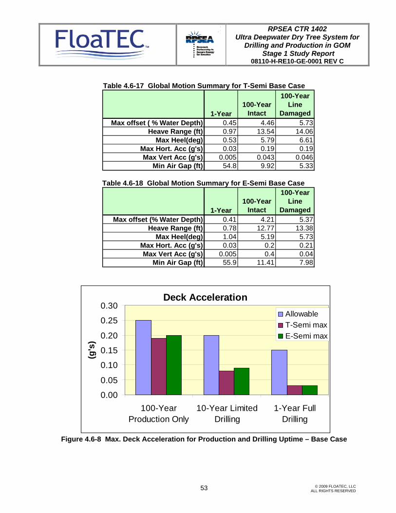
Table 4.6-17 and 4.6-18 summarize the global motions of the base case T-Semi and E-Semi, respectively, for the 1 year, 100 year intact and 100 year broken line conditions. The motions are all within the criteria. The maximum heave range is 13 ft – 14 ft for both hulls which make a significant effect on the tensioner stroke. The minimum air gap for T-Semi is 5.33 ft and 7.98 ft under the 100 year hurricane condition with one mooring line broken.

RPSEA CTR 1402 Ultra Deepwater Dry Tree System for
Drilling and Production in GOM Stage 1 Study Report
08110-H-RE10-GE-0001 REV C
© 2009 FLOATEC, LLC ALL RIGHTS RESERVED
52
Figure 4.6-8 and 4.6-9 show the maximum acceleration at the deck level and the offset as an indicator of the uptime for the production and drilling. All the motion is within the criteria. Figure 4.6-10 and 4.6-11 present the minimum safety factors of the most loaded mooring line for the base case at polyester and at chain, respectively. The safety factors are all larger than the required safety factors with some margin. The margin for 1 year operating condition is large, while that for 100 year hurricane condition intact and broken line is very small, which means that the mooring lines are well optimized for the critical condition.
Table 4.6-15 Natural Periods for Base Case
T-Semi E-Semi
Mode Period (sec) Period(sec)Surge 147.80 181.10Sway 153.00 187.50Heave 23.44 23.20Roll 26.70 40.57Pitch 26.00 40.14Yaw 55.60 65.60
Table 4.6-16 Natural Periods for Sensitivity Case
T-Semi E-SemiMode Period (sec) Period(sec)Surge 162.00 183.00Sway 164.60 187.00Heave 23.70 24.40Roll 26.40 32.20Pitch 25.40 31.90Yaw 53.50 67.10
RPSEA CTR 1402 Ultra Deepwater Dry Tree System for
Drilling and Production in GOM Stage 1 Study Report
08110-H-RE10-GE-0001 REV C
© 2009 FLOATEC, LLC ALL RIGHTS RESERVED
53
Table 4.6-17 Global Motion Summary for T-Semi Base Case
Table 4.6-18 Global Motion Summary for E-Semi Base Case
Figure 4.6-8 Max. Deck Acceleration for Production and Drilling Uptime – Base Case
Deck Acceleration
0.00
0.05
0.10
0.15
0.20
0.25
0.30
100-YearProduction Only
10-Year LimitedDrilling
1-Year FullDrilling
(g's
)
AllowableT-Semi maxE-Semi max
1-Year100-Year
Intact
100-Year Line
DamagedMax offset (% Water Depth) 0.41 4.21 5.37
Heave Range (ft) 0.78 12.77 13.38Max Heel(deg) 1.04 5.19 5.73
Max Hort. Acc (g's) 0.03 0.2 0.21Max Vert Acc (g's) 0.005 0.4 0.04
Min Air Gap (ft) 55.9 11.41 7.98
1-Year100-Year
Intact
100-Year Line
DamagedMax offset ( % Water Depth) 0.45 4.46 5.73
Heave Range (ft) 0.97 13.54 14.06Max Heel(deg) 0.53 5.79 6.61
Max Hort. Acc (g's) 0.03 0.19 0.19Max Vert Acc (g's) 0.005 0.043 0.046
Min Air Gap (ft) 54.8 9.92 5.33

RPSEA CTR 1402 Ultra Deepwater Dry Tree System for
Drilling and Production in GOM Stage 1 Study Report
08110-H-RE10-GE-0001 REV C
© 2009 FLOATEC, LLC ALL RIGHTS RESERVED
54
Figure 4.6-9 Max. Offset for Production and Drilling Uptime – Base Case
Figure 4.6-10 Minimum Safety Factors of Polyester Design– Base Case
Polyester
0.0
1.0
2.0
3.0
4.0
5.0
6.0
1-Year Intact 100-Year Intact 100-Year Damaged
Safe
ty F
acto
r
T-SemiE-SemiMin Allowable
Offset
0
2
4
6
8
10
100-YearProduction Only
10-Year LimitedDrilling
1-Year Full Drilling
(% w
ater
dep
th)
AllowableT-Semi maxE-Semi max

RPSEA CTR 1402 Ultra Deepwater Dry Tree System for
Drilling and Production in GOM Stage 1 Study Report
08110-H-RE10-GE-0001 REV C
© 2009 FLOATEC, LLC ALL RIGHTS RESERVED
55
Figure 4.6-11 Minimum Safety Factor at Chain – Base Case
Table 4.6-19 and 4.6-20 summarize the global motions of the sensitivity case T-Semi and E-Semi, respectively, for the 1 year, 100 year intact and 100 year broken line conditions. The motions are all within the criteria. The maximum heave range is 13 ft – 15 ft for both hulls which make a significant effect on the tensioner stroke. The minimum air gap for T-Semi is 6.56 ft and 8.48 ft under the 100 year hurricane condition with one mooring line broken.
Figure 4.6-12 and 4.6-13 present the minimum safety factors of the most loaded mooring line for the base case at polyester and at chain, respectively. The safety factors are all larger than the required safety factors and some margin. The margin for 1 year operating condition is large, while that for 100 year hurricane condition intact and broken line is very small, which means that the mooring lines are well optimized for the critical condition. The sensitivity case has more margin than the base case because the sensitivity is less optimized due to the limited time frame, and can be optimized at more detailed engineering Stage.
Chain
0.0
1.0
2.0
3.0
4.0
5.0
1-Year Intact 100-Year Intact 100-Year Damaged
Safe
ty F
acto
r T-SemiE-Semimin AllowableRequired

RPSEA CTR 1402 Ultra Deepwater Dry Tree System for
Drilling and Production in GOM Stage 1 Study Report
08110-H-RE10-GE-0001 REV C
© 2009 FLOATEC, LLC ALL RIGHTS RESERVED
56
Table 4.6-19 Global Motion Summary for T-Semi Sensitivity Case
Table 4.6-20 Global Motion Summary for E-Semi Sensitivity Case
Figure 4.6-12 Minimum Safety Factors at Polyester– Sensitivity Case
Polyester
0.0
1.02.0
3.0
4.0
5.06.0
7.0
1-Year Intact 100-Year Intact 100-Year Damaged
Safe
ty F
acto
r
T-SemiE-SemiMin Allowable
1-Year100-Year
Intact
100-Year Line
DamagedMax offset (% Water Depth) 0.4 4.22 5.43
Heave Range (ft) 0.71 13.34 13.96Max Heel(deg) 0.62 4.11 4.86
Max Hort. Acc (g's) 0.03 0.19 0.2Max Vert Acc (g's) 0.006 0.043 0.044
Min Air Gap (ft) 58.8 11.81 8.48
1-Year100-Year
Intact
100-Year Line
DamagedMax offset ( % Water Depth) 0.52 4.45 5.29
Heave Range (ft) 1.11 14.83 15.02Max Heel(deg) 0.81 5.94 6.51
Max Hort. Acc (g's) 0.02 0.18 0.18Max Vert Acc (g's) 0.006 0.043 0.044
Min Air Gap (ft) 56.2 9.16 6.56

RPSEA CTR 1402 Ultra Deepwater Dry Tree System for
Drilling and Production in GOM Stage 1 Study Report
08110-H-RE10-GE-0001 REV C
© 2009 FLOATEC, LLC ALL RIGHTS RESERVED
57
Figure 4.6-13 Minimum Safety Factors at Chain – Sensitivity Case
4.7 Hull Weights
The hull steel weights were initially estimated based on the volumetric weight(lbs/ft3) obtained from the detailed MTO engineering of the previous projects. Separate volumetric weights were applied to the column, the node and the pontoon. The volumetric weights were also adjusted in the in-house sizing tool as a function of draft and the area to volume ratio. The resulting hull steel weights are shown in Table 4.7-1 and Table 4.7-2. The ballast weight was determined so as to adjust the trim due to +/- 10 ft variation of topside horizontal eccentricity and to have enough GM to allow for the topside VCG changes of +/- 5 ft. Except for the trim ballast, more than 30% reserved ballast was considered at this phase for T-Semi. The E-Semi has more reserved ballast than T-Semi. It was assumed that the STP and the extendable column of the E-Semi was flooded, and the ballast in the STP and the extendable column is the fixed ballast which cannot be used for the trim adjustment.
Table 4.7-1 Weight of the T-Semi and E-Semi for Base Case
Chain
0.0
1.0
2.0
3.0
4.0
5.0
6.0
1-Year Intact 100-Year Intact 100-Year Damaged
Safe
ty F
acto
r T-SemiE-Semimin Allowable
26,50020,900Total hull steel weights incl. outfitting (s. t.)
47,80047,600Total payload (s. t.)20,60020,400TTR, SCR, Umbilicals, mooring27,20027,200Topside weights and storageE-SemiT-Semi
26,50020,900Total hull steel weights incl. outfitting (s. t.)
47,80047,600Total payload (s. t.)20,60020,400TTR, SCR, Umbilicals, mooring27,20027,200Topside weights and storageE-SemiT-Semi

RPSEA CTR 1402 Ultra Deepwater Dry Tree System for
Drilling and Production in GOM Stage 1 Study Report
08110-H-RE10-GE-0001 REV C
© 2009 FLOATEC, LLC ALL RIGHTS RESERVED
58
Table 4.7-2 Hull Weights for Sensitivity Case
T-Semi E-Semi Topside weights and storage 21,800 21,800
TTR, SCR, Umbilicals, mooring 15,300 15,500 Total payload (s.t.) 37,100 37,300
Total steel weights incl. outfitting
(s.t.) 18,400 24,000
4.8 Constructability
4.8.1 T-Semi : Hull and Truss Construction Installation
General This section outlines the proposed construction method for the T-Semi. The hull is planned to be built at the Keppel Offshore and Marine yards in South East Asia while the truss is planned to be built at the J. Ray McDermott yard in Altamira, Mexico. The scope of work includes the detailed design, shop drawing preparations, fabrication, assembly, outfitting and mechanical completion of the complete hull and truss followed by the quayside integration of the topsides. External party is to perform combined system level post-installation, hook-ups, testing and commissioning. Upon completion, the integrated hull and topside is loaded onto a heavy lift transport vessel, transported and delivered to Gulf of Mexico for integration with the truss and final installation of the FPS.
Hull Construction and Topside Integration Method In general, during the block assembly stage, steel outfitting, electrical penetrations, piping penetration, ventilation inserts, equipment foundations, steel partitions, various supports, anodes, etc. are installed where possible. The aim is to install as many as possible the items that require hot-work (welding) during this assembly stage prior to painting. Once painted, the blocks are to be outfitted with mechanical equipment, electrical cable trays or wire-

RPSEA CTR 1402 Ultra Deepwater Dry Tree System for
Drilling and Production in GOM Stage 1 Study Report
08110-H-RE10-GE-0001 REV C
© 2009 FLOATEC, LLC ALL RIGHTS RESERVED
59
ways, insulation, ductwork, etc. where possible and made ready for erection. Outfitting work is to be completed as much as possible during this stage to complete the blocks on land prior to erection. Those items that cannot be installed due to weight restrictions, interference or at boundary location (i.e. located at inter-block boundaries) are to be installed after the block has been erected. The construction of the Hull is planned to be in the following sequence.
1. Fabricate and outfit large blocks of pontoon, columns and nodes for eventual erection and assembly in graving dock at the Keppel Offshore and Marine Pioneer Yard;
2. Erect columns and complete remaining outfitting works alongside the quay after the hull has been undocked;
3. Mechanically complete and pre-commission the hull systems (independent of the topsides) to the maximum extent possible alongside the quay prior to integration of topsides;
4. Integrate the topside alongside the quay. Client will provide external services to perform combined system level post-installation, hook-ups, testing and commissioning. After which, T-Semi is to be loaded and sea-fastened onto a heavy lift transport vessel for dry tow to Gulf of Mexico for truss integration and final installation at site.

RPSEA CTR 1402 Ultra Deepwater Dry Tree System for
Drilling and Production in GOM Stage 1 Study Report
08110-H-RE10-GE-0001 REV C
© 2009 FLOATEC, LLC ALL RIGHTS RESERVED
60

RPSEA CTR 1402 Ultra Deepwater Dry Tree System for
Drilling and Production in GOM Stage 1 Study Report
08110-H-RE10-GE-0001 REV C
© 2009 FLOATEC, LLC ALL RIGHTS RESERVED
61
Truss Construction and Loadout The truss is planned to be built at the J. Ray McDermott Altamira yard in Mexico. Standard jacket type construction shall be adopted using the bent type method that follows the following sequence:
1. One of the truss bents will be laid out and assembled on the loadout skidway.
2. In parallel, the mating bent, the truss heave plates and the side bents’ X-braces shall be preassembled at ground level in an adjacent area to the skidway.
3. Upon completion of the preassemblies, the heave plates and the side X-braces are lifted and installed onto the truss bent assembly on the skidway.
4. After the heave plates and the side X-braces are fully welded to the bent on skidway, the mating bent shall be lifted, floated over and fitted and welded to the heave plates and the side X-braces.
5. On completion of all the welding work and final acceptance of the truss assembly, the assembly shall be loaded out onto the designated cargo barge and transported to the launch and mating-to-hull site. Skidding of the truss for the loadout shall be accomplished using one of the standard jacket pulling systems (strand jacks) or the hydraulic push/pull systems.
RPSEA CTR 1402 Ultra Deepwater Dry Tree System for
Drilling and Production in GOM Stage 1 Study Report
08110-H-RE10-GE-0001 REV C
© 2009 FLOATEC, LLC ALL RIGHTS RESERVED
62
T-Semi : Hull and Truss Mating and Installation
Phase 1 – Preinstallation of the Mooring System 1. Conduct onshore inspection, preparation, loadout and sail away of the first set of
mooring components (depends on area and capacity of the cargo barge).
2. Meanwhile, dispatch survey vessel to site to set-up the acoustic survey system and the markers for anchor pile placement.
3. Mobilize Installation Vessel (i.e. derrick barge).
4. Commence installation of first set of mooring components (piles, ground chains and pendant lines with recovery buoy).
5. Meanwhile, return the cargo barge to the shore base for repeating the load-out and traveling to site with the following set of the mooring components.
6. Repeat steps 4. & 5. until all mooring lines are preinstalled.
7. Recover installation aids and de-mobilize equipment.
8. Prepare the installation vessel for the second phase.
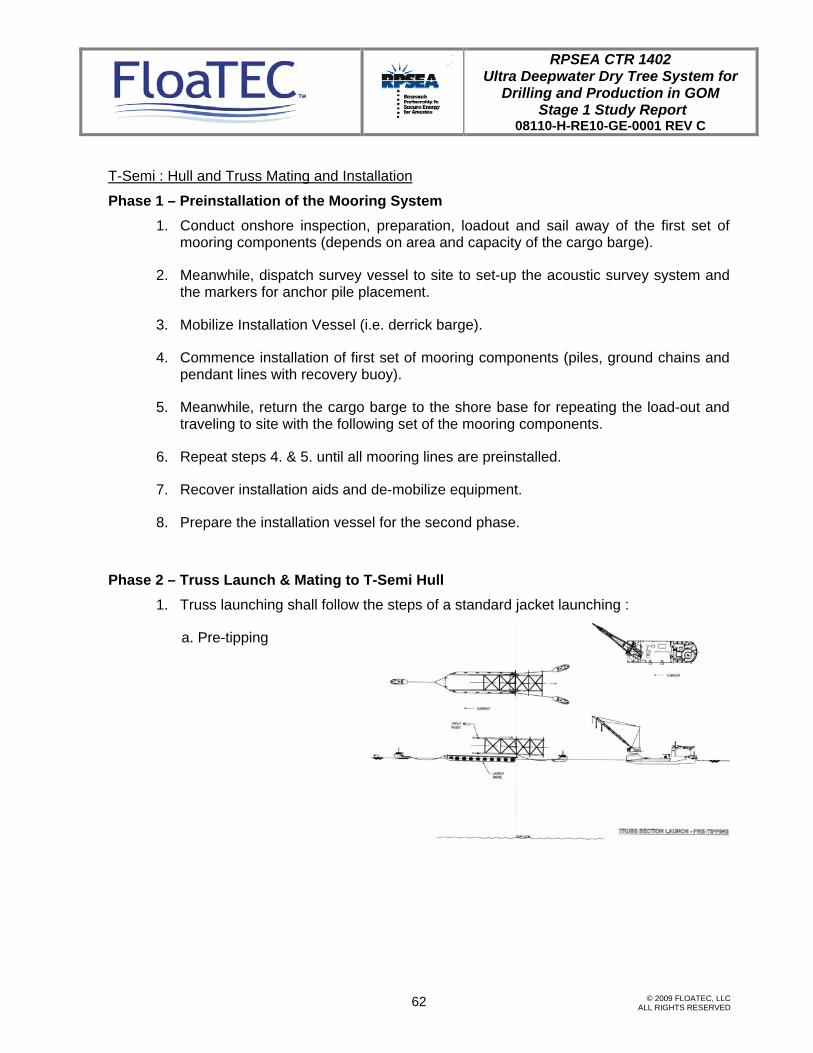
Phase 2 – Truss Launch & Mating to T-Semi Hull 1. Truss launching shall follow the steps of a standard jacket launching :
a. Pre-tipping

RPSEA CTR 1402 Ultra Deepwater Dry Tree System for
Drilling and Production in GOM Stage 1 Study Report
08110-H-RE10-GE-0001 REV C
© 2009 FLOATEC, LLC ALL RIGHTS RESERVED
63
b. Tipping
c. Separation
2. Lower truss to sea bed (Grounding) :
a. Control mooring with 4 tugs & rig to DB

RPSEA CTR 1402 Ultra Deepwater Dry Tree System for
Drilling and Production in GOM Stage 1 Study Report
08110-H-RE10-GE-0001 REV C
© 2009 FLOATEC, LLC ALL RIGHTS RESERVED
64
b. Lower to Seabed
3. Mating with Hull :
a. Control mooring with 4 tugs & tow to truss
b. Maneuver and position over truss.

RPSEA CTR 1402 Ultra Deepwater Dry Tree System for
Drilling and Production in GOM Stage 1 Study Report
08110-H-RE10-GE-0001 REV C
© 2009 FLOATEC, LLC ALL RIGHTS RESERVED
65
c. Rig truss to hull winches.
d. Lift truss to mating sleeves on hull. Complete fitting & welding/ grouting truss columns to hull sleeves.
e. Tow assembly to installation site.

RPSEA CTR 1402 Ultra Deepwater Dry Tree System for
Drilling and Production in GOM Stage 1 Study Report
08110-H-RE10-GE-0001 REV C
© 2009 FLOATEC, LLC ALL RIGHTS RESERVED
66
Phase 3 – T-Semi Mooring Lines Installation
a. secure T-Semi with a mooring line at each corner to achieve storm safe mooring.
b. Complete installation of remaining mooring lines.
RPSEA CTR 1402 Ultra Deepwater Dry Tree System for
Drilling and Production in GOM Stage 1 Study Report
08110-H-RE10-GE-0001 REV C
© 2009 FLOATEC, LLC ALL RIGHTS RESERVED
67
4.8.2 E-Semi : Hull Construction & Installation
General
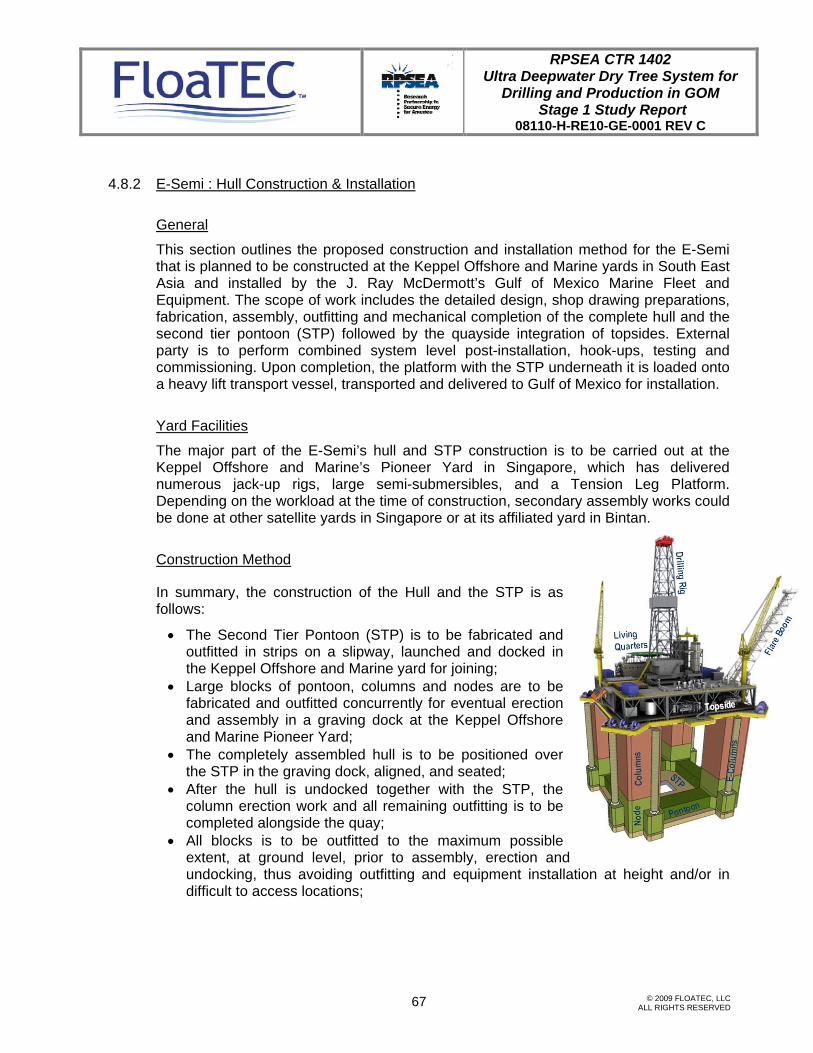
This section outlines the proposed construction and installation method for the E-Semi that is planned to be constructed at the Keppel Offshore and Marine yards in South East Asia and installed by the J. Ray McDermott’s Gulf of Mexico Marine Fleet and Equipment. The scope of work includes the detailed design, shop drawing preparations, fabrication, assembly, outfitting and mechanical completion of the complete hull and the second tier pontoon (STP) followed by the quayside integration of topsides. External party is to perform combined system level post-installation, hook-ups, testing and commissioning. Upon completion, the platform with the STP underneath it is loaded onto a heavy lift transport vessel, transported and delivered to Gulf of Mexico for installation.
Yard Facilities
The major part of the E-Semi’s hull and STP construction is to be carried out at the Keppel Offshore and Marine’s Pioneer Yard in Singapore, which has delivered numerous jack-up rigs, large semi-submersibles, and a Tension Leg Platform. Depending on the workload at the time of construction, secondary assembly works could be done at other satellite yards in Singapore or at its affiliated yard in Bintan.
Construction Method
In summary, the construction of the Hull and the STP is as follows:
• The Second Tier Pontoon (STP) is to be fabricated and outfitted in strips on a slipway, launched and docked in the Keppel Offshore and Marine yard for joining;
• Large blocks of pontoon, columns and nodes are to be fabricated and outfitted concurrently for eventual erection and assembly in a graving dock at the Keppel Offshore and Marine Pioneer Yard;
• The completely assembled hull is to be positioned over the STP in the graving dock, aligned, and seated;
• After the hull is undocked together with the STP, the column erection work and all remaining outfitting is to be completed alongside the quay;
• All blocks is to be outfitted to the maximum possible extent, at ground level, prior to assembly, erection and undocking, thus avoiding outfitting and equipment installation at height and/or in difficult to access locations;

RPSEA CTR 1402 Ultra Deepwater Dry Tree System for
Drilling and Production in GOM Stage 1 Study Report
08110-H-RE10-GE-0001 REV C
© 2009 FLOATEC, LLC ALL RIGHTS RESERVED
68
• The hull systems are to be mechanically completed in full ms (independent of the
topsides) pre-commissioned to the maximum extent possible alongside prior to integration of the topsides;
• After topside integration, the E-Semi is to be loaded and sea-fastened onto a heavy lift transport vessel for dry tow to the Gulf of Mexico for installation.
Hull and Second Tier Pontoon
Block Breakdown
For construction purposes, the hull is divided into nodes, pontoons and columns. Each pontoon or column is further broken down into smaller blocks. The nodes and pontoons are planned to be split into four (4) nodes and approximately eight (8) pontoon blocks depending on the size and weight of the pontoon. The columns are likely to be divided into two (2) blocks per column depending on the weight of the columns. The Second Tier Pontoon is to be split into nine (9) blocks.
Block Fabrication
Raw materials, such as steel plates, stiffeners, etc. are delivered to the respective yards material receiving bays or stockyard areas for proper storage and retrieval. After being checked for physical defects and verified of their mill origin, they are sent for blasting and construction prime coating. Overhead gantry cranes are used to transfer the steel plates. Magnetic devices are used for lifting and transferring steel plates.
Panel fabrication for all blocks is to be carried out in the panel fabrication lines at the respective yards’ Panel Fabrication shops. The hull is conveniently divided into structural blocks as mentioned in the preceding section. The nine (9) second tier pontoon blocks are to be joined into three (3) strips. Each of the blocks and strips is fabricated, assembled and outfitted as an individual unit prior to erection.

RPSEA CTR 1402 Ultra Deepwater Dry Tree System for
Drilling and Production in GOM Stage 1 Study Report
08110-H-RE10-GE-0001 REV C
© 2009 FLOATEC, LLC ALL RIGHTS RESERVED
69
Block Assembly
In general, during the block assembly stage, steel outfitting, electrical penetrations, piping penetration, ventilation inserts, equipment foundations, steel partitions, various supports, anodes, etc. are installed where possible. The aim is to install as many items as possible that require hot-work (welding) during this assembly stage prior to painting. Once painted, the blocks are to be outfitted with mechanical equipment, electrical cable trays or wire-ways, insulation, ductwork, etc. where possible and readied for erection. Outfitting work is to be completed as much as possible during this stage to complete the blocks on land prior to erection. Those items that cannot be installed due to weight restrictions, interference or at boundary location (i.e. located at inter-block boundaries) are to be installed after the block has been erected.
Assembly of Node Blocks
There are four node blocks. Each represents the corner of the Hull where the pontoon and the columns meet. Each of the four (4) nodal blocks (incl. the two connectors) could be assembled from sub-blocks as shown on the right. This sketch shows how each of these sub-blocks are planned to be assembled. The four (4) nodal blocks are to be made from smaller sub-blocks and assembled at a location where it can later be lifted and erected inside the dry-dock using a crane of suitable capacity.
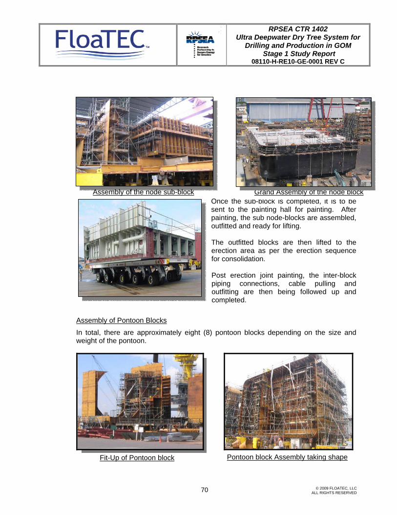
RPSEA CTR 1402 Ultra Deepwater Dry Tree System for
Drilling and Production in GOM Stage 1 Study Report
08110-H-RE10-GE-0001 REV C
© 2009 FLOATEC, LLC ALL RIGHTS RESERVED
70
Once the sub-block is completed, it is to be
sent to the painting hall for painting. After painting, the sub node-blocks are assembled, outfitted and ready for lifting.
The outfitted blocks are then lifted to the erection area as per the erection sequence for consolidation.
Post erection joint painting, the inter-block piping connections, cable pulling and outfitting are then being followed up and completed.
Assembly of Pontoon Blocks
In total, there are approximately eight (8) pontoon blocks depending on the size and weight of the pontoon.
Assembly of the node sub-block Grand Assembly of the node block
Fit-Up of Pontoon block Pontoon block Assembly taking shape

RPSEA CTR 1402 Ultra Deepwater Dry Tree System for
Drilling and Production in GOM Stage 1 Study Report
08110-H-RE10-GE-0001 REV C
© 2009 FLOATEC, LLC ALL RIGHTS RESERVED
71
Once the pontoon blocks are assembled, it is to be sent to the painting hall for painting or painted in-situ, depending on size of the block. This is followed by block outfitting. All pre-outfitted and painted nodes as well as pontoon blocks are to be erected and assembled in the dry dock using a crane of suitable capacity.
Assembly of Column Blocks
The four (4) columns are each made up of at least two (2) blocks and may be further sub-divided into two (2) or three (3) manageable sub-blocks depending on their weights and sizes. Once the assembly of the column blocks is completed, it is to be sent to the painting hall for painting. After painting, the two (2) column blocks are to be outfitted and 'stacked' to form the full column. Upon completion, it is to be readied for lifting and erected onto the nodes.
Column Assembly
Sub-block Assembly
Outfitting and Assembly of blocks Ready for erection
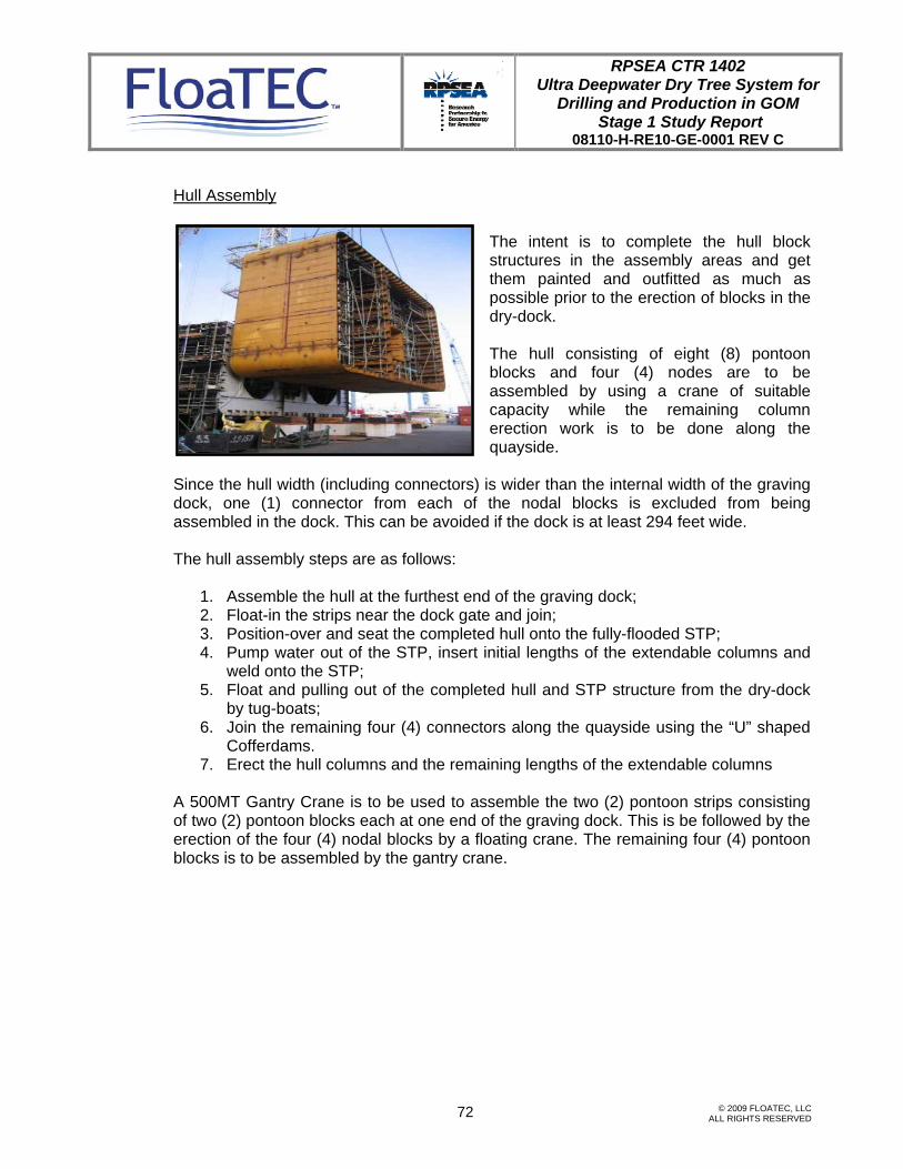
RPSEA CTR 1402 Ultra Deepwater Dry Tree System for
Drilling and Production in GOM Stage 1 Study Report
08110-H-RE10-GE-0001 REV C
© 2009 FLOATEC, LLC ALL RIGHTS RESERVED
72
Hull Assembly
The intent is to complete the hull block structures in the assembly areas and get them painted and outfitted as much as possible prior to the erection of blocks in the dry-dock.
The hull consisting of eight (8) pontoon blocks and four (4) nodes are to be assembled by using a crane of suitable capacity while the remaining column erection work is to be done along the quayside.
Since the hull width (including connectors) is wider than the internal width of the graving dock, one (1) connector from each of the nodal blocks is excluded from being assembled in the dock. This can be avoided if the dock is at least 294 feet wide. The hull assembly steps are as follows:
1. Assemble the hull at the furthest end of the graving dock; 2. Float-in the strips near the dock gate and join; 3. Position-over and seat the completed hull onto the fully-flooded STP; 4. Pump water out of the STP, insert initial lengths of the extendable columns and
weld onto the STP; 5. Float and pulling out of the completed hull and STP structure from the dry-dock
by tug-boats; 6. Join the remaining four (4) connectors along the quayside using the “U” shaped
Cofferdams. 7. Erect the hull columns and the remaining lengths of the extendable columns
A 500MT Gantry Crane is to be used to assemble the two (2) pontoon strips consisting of two (2) pontoon blocks each at one end of the graving dock. This is be followed by the erection of the four (4) nodal blocks by a floating crane. The remaining four (4) pontoon blocks is to be assembled by the gantry crane.

RPSEA CTR 1402 Ultra Deepwater Dry Tree System for
Drilling and Production in GOM Stage 1 Study Report
08110-H-RE10-GE-0001 REV C
© 2009 FLOATEC, LLC ALL RIGHTS RESERVED
73
While the pontoons and nodes are completely welded, all external works including painting are completed. All appurtenances attached to the pontoons and nodes such as fairleads, caisson supports, reinforcements etc. are to be completed prior to the block erection or in dry-dock, whichever is more practical. Assembly of Second Tier Pontoon (STP)
The E-Semi’s STP is to be fabricated and assembled in strips on slipways at a nearby affiliated yard in Singapore.
The strips are to be outfitted as much as possible to complete the second tier pontoon on land prior to launch.
By using intermediate dock gates, this allows the docking of STP near the dock gate and next to the hull assembly area.
Once seated on the pre-laid keel blocks in the dock, the strips are joined.

RPSEA CTR 1402 Ultra Deepwater Dry Tree System for
Drilling and Production in GOM Stage 1 Study Report
08110-H-RE10-GE-0001 REV C
© 2009 FLOATEC, LLC ALL RIGHTS RESERVED
74
Joining of Hull and Second Tier Pontoon (STP)
Once the second tier pontoon strips are joined, the whole assembly is to be fully ballasted. Upon completion of the hull assembly, the intermediate dock gate is to be removed and the dock is to be flooded. By using mooring and tug boats, the hull is positioned above the second tier pontoon.
The theodolites and guiding brackets at the STP are used to ensure the alignment of the connectors prior to seating of the hull onto the fully-flooded STP.
The water in the STP is to be pumped or drained out and eight (8) initial lengths of the
extendable columns (E-Columns) are to be inserted into the eight (8) connectors using gantry crane and welded onto the STP. The keel blocks between the hull and the STP are removed and the hull is gently lowered onto the STP by using the strand-jacks or other devices. Once completed, the dock is flooded and the completed hull together with the STP is undocked and moored with a spacer barge alongside the quay to perform the joining of the four (4) STP connectors using the cofferdams. With the quayside draft of this configuration still at the STP depth and with sufficient freeboard to ensure work safety, the four (4) pre-outfitted hull connectors are to be installed using the floating crane or the land cranes.
Initial length of E-Columns

RPSEA CTR 1402 Ultra Deepwater Dry Tree System for
Drilling and Production in GOM Stage 1 Study Report
08110-H-RE10-GE-0001 REV C
© 2009 FLOATEC, LLC ALL RIGHTS RESERVED
75
Erection of Hull Columns and Extendable Columns (E-Columns)
Once the connectors are completely installed to the hull, the erection of the columns begins. Each column block would have already been consolidated as a single major column block prior to erection along the quayside. The assembly to form the full four (4) column blocks is done on land and all equipment on flats in the column blocks would have been installed and hooked up inside the column blocks prior to lift. The columns are erected as one piece using a floating crane of suitable capacity.
“U”-shaped Cofferdam
The four (4) STP connectors mated by cofferdam
The four (4) hull connectors installed using floating crane
Spacer barge

RPSEA CTR 1402 Ultra Deepwater Dry Tree System for
Drilling and Production in GOM Stage 1 Study Report
08110-H-RE10-GE-0001 REV C
© 2009 FLOATEC, LLC ALL RIGHTS RESERVED
76
Each column block prior to the final lift is to be outfitted to the maximum possible extent. Where possible, equipment, piping, ductwork, E&I trays, steel outfits, etc., are to be installed in the block prior to erection of the block itself. Those that cannot be installed due to weight restrictions, interference or items’ location (i.e. located at inter-block boundaries) are to be installed after the block has been erected. The remaining length of the extendable columns are lowered and installed in the same manner. Temporary column support structures, if necessary and as designed by engineering are to be installed prior to the topside integration.
Hull Column lifted from assembly location

RPSEA CTR 1402 Ultra Deepwater Dry Tree System for
Drilling and Production in GOM Stage 1 Study Report
08110-H-RE10-GE-0001 REV C
© 2009 FLOATEC, LLC ALL RIGHTS RESERVED
77
Hull Appurtenances
All appurtenances are to be prefabricated, painted and installed on the respective blocks before the painting of the blocks. Appurtenances that are long and across block boundaries such as the J-tubes, Riser Pipes, caissons etc. which are attached to the hull column are to be installed after the blocks are erected. When the columns are joined to the nodes, the hull system completions commence. The piping and electrical works left out as a consequence of the erection are completed, leading to full mechanical completion of each system. This is followed by marine testing and commissioning of the hull for parts of the systems that could not be completed in the dry dock. Onshore commissioning is done as much as possible prior to transportation of the hull.
Topside Integration Receiving and installing Topside Modules Topside construction is performed by an external yard determined and awarded by the client. The topsides is to arrive in modules with size and weight determined by the integration yard. Onshore testing and pre-commissioning activities are performed at the topside construction yard by the client or external party by systems at the module level on ground to the maximum extent possible.

RPSEA CTR 1402 Ultra Deepwater Dry Tree System for
Drilling and Production in GOM Stage 1 Study Report
08110-H-RE10-GE-0001 REV C
© 2009 FLOATEC, LLC ALL RIGHTS RESERVED
78
The topside Modules are to arrive on barges. The inter-modular deck structures, the spools and the other hookup items are to be shipped loose together with the modules. These could be strapped onto the deck at areas close to their final location or packed in boxes placed in the respective modules. Appropriate procedure, trim/heel conditions, lift analysis, client approval, etc. are to be completed prior to the integration. Job safety analysis also forms part of the procedure. Integration yard’s responsibility is only limited to the structural integration of the topside modules. The client is to provide external services to perform the combined system level post-installation, hook-ups, testing and commissioning. Upon completion, the platform with STP underneath it is loaded onto a heavy lift transport vessel, transported, and delivered to Gulf of Mexico for installation. E-Semi offshore installation Phase 1 – Preinstallation of the Mooring System 1. Onshore inspection, preparation, loadout and sail away of the first set of mooring
components (depends on area and capacity of cargo barge).
2. Meanwhile, survey vessel is dispatched to site to set-up the acoustic survey system and markers for anchor pile placement.
3. Mobilize Installation Vessel (i.e. derrick barge).

RPSEA CTR 1402 Ultra Deepwater Dry Tree System for
Drilling and Production in GOM Stage 1 Study Report
08110-H-RE10-GE-0001 REV C
© 2009 FLOATEC, LLC ALL RIGHTS RESERVED
79
4. Commence installation of the first set of mooring components (piles, ground chains and pendant line with recovery buoy).
5. Meanwhile, cargo barge returns to shore base and repeats the load-out and travels to site with the following set of the mooring components.
6. Repeat steps 4. & 5. until all mooring lines are preinstalled.
7. Recover installation aids and de-mobilize equipment.
8. Prepare the installation vessel for the next phase.
Phase 2 – Hull Floatoff, Tow to Site and Installation Upon floating off the integrated hull & topsides (i.e., FPS) from the transporting heavy lift vessel, the FPS will undergo the following steps for installation:
1. Moor the FPS to tow tugs and tow to installation site.

RPSEA CTR 1402 Ultra Deepwater Dry Tree System for
Drilling and Production in GOM Stage 1 Study Report
08110-H-RE10-GE-0001 REV C
© 2009 FLOATEC, LLC ALL RIGHTS RESERVED
80
2. Upon arrival to site, change tow tugs mooring configuration to hold the FPS in final installation location.
3. Ballast the FPS to final operating draft. The derrick barge is to install one mooring line per corner of the FPS to satisfy storm safe condition and release tow tugs.

RPSEA CTR 1402 Ultra Deepwater Dry Tree System for
Drilling and Production in GOM Stage 1 Study Report
08110-H-RE10-GE-0001 REV C
© 2009 FLOATEC, LLC ALL RIGHTS RESERVED
81
4. Lower the STP to its final position using respective mooring lines’ chain jack system. Retract the STP lowering lines and install the remaining mooring lines followed by grouting the STP column connections to achieve operating condition.

RPSEA CTR 1402 Ultra Deepwater Dry Tree System for
Drilling and Production in GOM Stage 1 Study Report
08110-H-RE10-GE-0001 REV C
© 2009 FLOATEC, LLC ALL RIGHTS RESERVED
82
4.9 Preliminary Project Execution Plan and Schedule
4.9.1 Introduction
General
This section outlines the preliminary execution plan and the schedule for both the E-Semi and the T-Semi.
Preliminary Execution Plan
Keppel Offshore and Marine (KOM), J. Ray McDermott (JRM) along with FloaTEC, LLC will follow the strategies built up from many previously completed successful projects. The front-end engineering design followed by detailed design drawings will be prepared prior to developing construction drawings. The preparation of red-lines for as-built drawings at the end of the construction will follow. KOM and JRM will utilize their existing purchasing and warehouse departments to perform material procurement and expediting, receipt, storage, preservation and issuance activities. Supporting and tracking systems are utilized to control and issue materials. Project QA Superintendents will be responsible for the project quality assurance, quality control, quality certification and dimensional control at the respective yards. Yards’ Project planners will be responsible for project control, reporting and progress measurement in accordance with the established Project Control and Progress Measurement Procedures. The yards’ Project Safety Officer and his teams will be responsible to prepare, manage and implement the project HSE plan in accordance with contract requirements and existing safety programs. Both Semi’s hulls and the E-Semi’s STP construction are to be carried out at the Keppel Offshore and Marine’s Pioneer Yard in Singapore, which has delivered numerous jack-up rigs, large Semi-submersibles, and a Tension Leg Platform. The Truss for the T-Semi is to be carried out at the J. Ray McDermott’s yard in Altamira, Mexico, utilizing J. Ray McDermott’s extensive worldwide expertise that has delivered numerous jacket platforms and Spar hulls. Topside construction is performed by a third party under Client management. The topside is to arrive in modules tested and pre-commissioned with sizes and weights

RPSEA CTR 1402 Ultra Deepwater Dry Tree System for
Drilling and Production in GOM Stage 1 Study Report
08110-H-RE10-GE-0001 REV C
© 2009 FLOATEC, LLC ALL RIGHTS RESERVED
83
jointly determined by the topside engineering entity, the topside fabrication yard and the topside integration yard.
Integration yard’s responsibility will be the structural integration of the topside modules. Client will provide the necessary services to perform combined system level post-installation, hook-ups, testing and commissioning.

RPSEA CTR 1402 Ultra Deepwater Dry Tree System for
Drilling and Production in GOM Stage 1 Study Report
08110-H-RE10-GE-0001 REV C
84 © 2009 FLOATEC, LLC ALL RIGHTS RESERVED
4.9.2 Preliminary Schedule

RPSEA CTR 1402 Ultra Deepwater Dry Tree System for
Drilling and Production in GOM Stage 1 Study Report
08110-H-RE10-GE-0001 REV C
85 © 2009 FLOATEC, LLC ALL RIGHTS RESERVED
5.0 CONCLUSIONS AND RECOMMENDATIONS
Conclusions The study results summarized in this report have definitely proven that both the E-Semi and the T-Semi design concepts are applicable for 8,000 feet waters in the Gulf of Mexico and for the two payload cases as specified by RPSEA. The global performance of these two concepts has met the RPSEA design criteria. These concepts utilize off- the-shelf riser tensioner design. Hull construction requires only existing yard facilities. Topside/hull integration can be carried out either at the quay side or by alternative schemes such as float-over. For the E-Semi, lowering the Second Tier Pontoon, i.e., the STP, at the final installation site and securing the STP to the hull require no new technology. For the T-Semi, installing the truss-supported heave plates utilizes the conventional jacket launch barge and marine equipment as well as proven marine operation procedures. Compared to Spar for the same functional requirements and metocean conditions, the results of this Stage 1 study clearly show that these two semisubmersible design concepts can be designed to have comparable global performance. Furthermore, they offer better operability than the Spar in that they can accommodate all facilities on only two decks as opposed to three decks in the case of a Spar. In summary, the work FloaTEC accomplished in Stage 1 has met the major RPSEA study objective in that the E-Semi and the T-Semi have been shown to be competitive against the Spar for ultra-deep-water production and drilling applications in the Gulf of Mexico. It should be noted that the analytical results were produced with tools that had been calibrated with model test data. Key attributes of these concepts are:
• Conventional hull, topsides and truss construction methods • Flexible hull / topsides integration methods • No transportation constraints • No installation constraints • Conventional connection designs • New application of existing technologies • Scalable design accommodates a range of applications
Recommendations It is recommended that, during Stage 2, the hull configuration should be further optimized and additional structural analysis and hull scantling should be carried out to better estimate the steel quantities. Fatigue analysis of the riser components and the structural connections should also be performed. Detailed installation engineering

RPSEA CTR 1402 Ultra Deepwater Dry Tree System for
Drilling and Production in GOM Stage 1 Study Report
08110-H-RE10-GE-0001 REV C
86 © 2009 FLOATEC, LLC ALL RIGHTS RESERVED
should be carried out. Then, cost and schedule estimates can be developed with better accuracy.

![AMAZON ULTRA-DEEPWATER J-LAY VESSEL...AMAZON ULTRA-DEEPWATER J-LAY VESSEL 24M062018H-14 03012019 Highlights Fully enclosed 1,653 ST [1,500 MT] dynamic hex joint J-Lay system rated](https://img.pdfslide.us/doc/110x75/5fc95ac8f4c1aa228e7de9ab/amazon-ultra-deepwater-j-lay-vessel-amazon-ultra-deepwater-j-lay-vessel-24m062018h-14.jpg)