Embed Size (px)
Citation preview
RPP-RPT-48194
Revision 0
Fiscal Year 2010 Visual Inspection Report for Single-Shell Tanks
J.P. Robocker
Washington River Protection Solutions
Date Published
November 2010
Prepared for the U.S. Department of Energy
Office of River Protection
Contract No. DE-AC27-08RV14800
RPP-RPT-48194, Rev. 0
ii
EXECUTIVE SUMMARY
The mission of the River Protection Project (RPP) is to store, retrieve, treat, and dispose of the
highly radioactive waste stored in the Hanford Site tanks in an environmentally-sound, safe, and
cost-effective manner. The waste is contained in 149 single-shell tanks (SST) and 28 double-
shell tanks (DST). The tanks contain more than 50 million gallons of waste (Rogers, 2010).
The SSTs were constructed between 1944 and 1965. The structural integrity of the SSTs was
assessed in 2002(Rifaey, 2002) against an expected retrieval completion date of 2018. Recently
the SST retrieval completion date was extended and many of the SSTs are expected to hold
waste for an additional 30 years.
As part of an enhanced SST Integrity Project, responding to the need for tank life extension, the
visual inspection program was launched in fiscal year (FY) 2010. The program evaluates the
structural integrity of the tanks using a digital video camera inserted into the tanks via an access
riser. In this way, the visible concrete above the tank liner can be examined. Special attention is
paid to the upper haunch area of the tank because it is the area of highest stress. Although not
related to structural integrity, video of the inside of the tank also gives insight to the condition of
the steel liner and in-tank equipment.
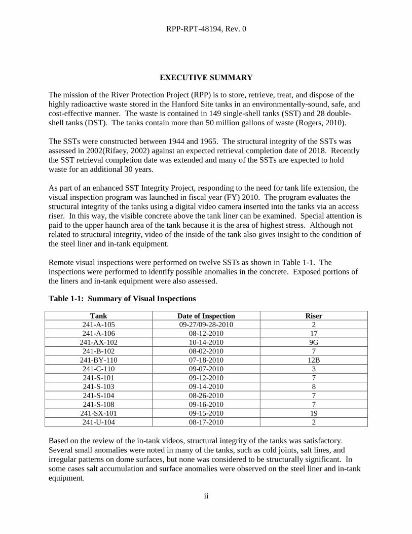
Remote visual inspections were performed on twelve SSTs as shown in Table 1-1. The
inspections were performed to identify possible anomalies in the concrete. Exposed portions of
the liners and in-tank equipment were also assessed.
Table 1-1: Summary of Visual Inspections
Tank Date of Inspection Riser
241-A-105 09-27/09-28-2010 2
241-A-106 08-12-2010 17
241-AX-102 10-14-2010 9G
241-B-102 08-02-2010 7
241-BY-110 07-18-2010 12B
241-C-110 09-07-2010 3
241-S-101 09-12-2010 7
241-S-103 09-14-2010 8
241-S-104 08-26-2010 7
241-S-108 09-16-2010 7
241-SX-101 09-15-2010 19
241-U-104 08-17-2010 2
Based on the review of the in-tank videos, structural integrity of the tanks was satisfactory.
Several small anomalies were noted in many of the tanks, such as cold joints, salt lines, and
irregular patterns on dome surfaces, but none was considered to be structurally significant. In
some cases salt accumulation and surface anomalies were observed on the steel liner and in-tank
equipment.
RPP-RPT-48194, Rev. 0
iii
TABLE OF CONTENTS
Executive summary ......................................................................................................................... ii
1.0 Introduction .......................................................................................................................... 1
2.0 Tank Design ......................................................................................................................... 2
3.0 Scope of Single-Shell Tank Visual Inspection .................................................................... 4
3.1 Single-shell Tank Visual Inspection Criteria ................................................................... 7
4.0 Method of Inspection ......................................................................................................... 11
4.1 Inspection Equipment ..................................................................................................... 11
5.0 Tank 241-A-105 ................................................................................................................. 12
5.1 Results and Conclusion .................................................................................................. 12
5.2 Recommendations .......................................................................................................... 17
6.0 Tank 241-A-106 ................................................................................................................. 18
6.1 Results and Conclusion .................................................................................................. 18
6.2 Recommendations .......................................................................................................... 21
7.0 Tank 241-AX-102 .............................................................................................................. 22
7.1 Results and Conclusion .................................................................................................. 22
7.2 Recommendations .......................................................................................................... 25
8.0 Tank 241-B-102 ................................................................................................................. 26
8.1 Results and Conclusion .................................................................................................. 26
8.2 Recommendations .......................................................................................................... 30
9.0 Tank 241-BY-110 .............................................................................................................. 31
9.1 Results and Conclusion .................................................................................................. 31
9.2 Recommendations .......................................................................................................... 36
10.0 Tank 241-C-110 ................................................................................................................. 37
10.1 Results and Conclusion .............................................................................................. 37
10.2 Recommendations ...................................................................................................... 40
11.0 Tank 241-S-101 ................................................................................................................. 41
11.1 Results and Conclusion .............................................................................................. 41
11.2 Recommendations ...................................................................................................... 44
12.0 Tank 241-S-103 ................................................................................................................. 45
12.1 Results and Conclusion .............................................................................................. 45
12.2 Recommendations ...................................................................................................... 49
13.0 Tank 241-S-104 ................................................................................................................. 50
13.1 Results and Conclusion .............................................................................................. 50
RPP-RPT-48194, Rev. 0
iv
13.2 Recommendations ...................................................................................................... 53
14.0 Tank 241-S-108 ................................................................................................................. 54
14.1 Results and Conclusion .............................................................................................. 54
14.2 Recommendations ...................................................................................................... 57
15.0 Tank 241-SX-101............................................................................................................... 58
15.1 Results and Conclusion .............................................................................................. 58
15.2 Recommendations ...................................................................................................... 61
16.0 Tank 241-U-104 ................................................................................................................. 62
16.1 Results and Conclusion .............................................................................................. 62
16.2 Recommendations ...................................................................................................... 66
17.0 Works Cited ....................................................................................................................... 67
LIST OF FIGURES
Figure 2-1: Single-shell Tank Types.............................................................................................. 3 Figure 3-1: SST Concrete Dome General Inspection Regions ...................................................... 6 Figure 3-2: Possible Concrete Cracking and Spalling (Tank 241-S-112) ..................................... 7
Figure 3-3: Tar Rings (Tank 241-BY-107) .................................................................................... 8 Figure 3-4: Signs of Liquid Intrusion (Tank 241-T-102) .............................................................. 9
Figure 3-5: Possible Steel Liner Crack (Tank 241-SX-112) ....................................................... 10
Figure 5-1: Tank 241-A-105 Concrete Dome .............................................................................. 12
Figure 5-2: Compilation of Photographs of Tank 241-A-105 Dome .......................................... 13 Figure 5-3: Concrete Anomaly .................................................................................................... 13
Figure 5-4: Tank 241-A-105 Steel Liner ..................................................................................... 14 Figure 5-5: Compilation of Photographs of Tank 241-A-105 Steel Liner ................................... 15 Figure 5-6: Tank 241-A-105 in 1981 ........................................................................................... 15
Figure 5-7: Tank 241-A-105 In-Tank Equipment/Risers ............................................................ 16 Figure 5-8: Tank 241-A-105 in 1981 ........................................................................................... 17
Figure 6-1: Tank 241-A-106 Concrete Dome .............................................................................. 18 Figure 6-2: Compilation of Photographs of Tank 241-A-106 Dome .......................................... 19 Figure 6-3: Tank 241-A-106 Steel Liner ..................................................................................... 20 Figure 6-4: Compilation of Photographs of Steel Liner Tank 241-A-106................................... 20 Figure 6-5: Tank 241-A-106 In-Tank Equipment/Risers ............................................................ 21
Figure 7-1: Tank 241-AX-102 Concrete Dome ........................................................................... 22 Figure 7-2: Compilation of Photographs of Tank 241-AX-102 Dome ........................................ 23
Figure 7-3: Concrete Anomaly .................................................................................................... 23 Figure 7-4: Tank 241-AX-102 Steel Liner .................................................................................. 24 Figure 7-5: Tank 241-AX-102 In-Tank Equipment/Risers ......................................................... 25 Figure 8-1: Tank 241-B-102 Concrete Dome .............................................................................. 26 Figure 8-2: Compilation of Photographs of Tank 241-B-102 Dome ........................................... 27 Figure 8-3: Tank 241-B-102 Steel Liner ..................................................................................... 27
RPP-RPT-48194, Rev. 0
v
Figure 8-4: Compilation of Photographs of Steel Liner Tank 241-B-102 ................................... 28
Figure 8-5: Tank 241-B-102 ........................................................................................................ 28 Figure 8-6: Steel Anomaly ........................................................................................................... 29 Figure 8-7: Steel Anomaly ........................................................................................................... 29
Figure 8-8: Tank 241-B-102 In-Tank Equipment/Risers............................................................. 29 Figure 9-1: Tank 241-BY-110 Concrete Dome ........................................................................... 31 Figure 9-2: Compilation of Photographs of Tank 241-BY-110 Dome ........................................ 32 Figure 9-3: Concrete Anomaly .................................................................................................... 32 Figure 9-4: Concrete Anomaly .................................................................................................... 32
Figure 9-5: Tank 241-BY-110 Steel Liner................................................................................... 33 Figure 9-6: Compilation of Photographs of Steel Liner Tank 241-BY-110 ................................ 34 Figure 9-7: Tank 241-BY-110 ..................................................................................................... 34 Figure 9-8: Tank 241-BY-110 In-Tank Equipment/Risers .......................................................... 35
Figure 10-1: Tank 241-C-110 Concrete Dome ............................................................................ 37 Figure 10-2: Compilation of Photographs of Tank 241-C-110 Dome ......................................... 38
Figure 10-3: Tank 241-C-110 Steel Liner ................................................................................... 38 Figure 10-4: Compilation of Photographs of Steel Liner Tank 241-C-110 ................................. 39
Figure 10-5: 241-C-110 ............................................................................................................... 39 Figure 10-6: Tank 241-C-110 In-Tank Equipment/Risers........................................................... 40 Figure 11-1: Tank 241-S-101 Concrete Dome ............................................................................ 41
Figure 11-2: Prior photo of Tank 241-S-101 ............................................................................... 41 Figure 11-3: Concrete Anomaly .................................................................................................. 42
Figure 11-4: Tank 241-S-101 Steel Liner .................................................................................... 43 Figure 11-5: Tank 241-S-101 Steel Liner .................................................................................... 43 Figure 11-6: Tank 241-S-101 in 1987 ......................................................................................... 43
Figure 11-7: Tank 241-S-101 In-Tank Equipment/Risers ........................................................... 44
Figure 12-1: Tank 241-S-103 Concrete Dome ............................................................................ 45 Figure 12-2: Compilation of Photographs of Tank 241-S-103Dome .......................................... 46 Figure 12-3: Concrete Anomaly .................................................................................................. 46
Figure 12-4: Concrete Anomaly .................................................................................................. 46 Figure 12-5: Tank 241-S-103 Steel Liner .................................................................................... 47
Figure 12-6: Compilation of Photographs of Steel Liner Tank 241-S-103 ................................. 47 Figure 12-7: Tank 241-S-103 in 1984 ......................................................................................... 48
Figure 12-8: Tank 241-S-103 In-Tank Equipment/Risers ........................................................... 49 Figure 13-1: Tank 241-S-104 Concrete Dome ............................................................................ 50 Figure 13-2: Concrete Anomaly .................................................................................................. 51 Figure 13-3: Tank 241-S-104 Steel Liner .................................................................................... 51 Figure 13-4: Tank 241-S-104 in 1984 ......................................................................................... 52
Figure 13-5: Steel Anomaly ......................................................................................................... 52 Figure 13-6: Tank 241-S-104 In-Tank Equipment/Risers ........................................................... 53
Figure 14-1: Tank 241-S-108 Concrete Dome ............................................................................ 54 Figure 14-2: Compilation of Photographs of Tank 241-S-108 Dome ......................................... 55 Figure 14-3: Concrete Anomaly .................................................................................................. 55 Figure 14-4: Concrete Anomaly .................................................................................................. 55 Figure 14-5: Tank 241-S-108 Steel Liner .................................................................................... 56 Figure 14-6: Tank 241-S-108 In-Tank Equipment/Risers ........................................................... 57
RPP-RPT-48194, Rev. 0
vi
Figure 15-1: Tank 241-SX-101 Concrete Dome ......................................................................... 58
Figure 15-2: Tank 241-SX-101 Steel Liner ................................................................................. 59 Figure 15-3: Tank 241-SX-101 in 1982....................................................................................... 59 Figure 15-4: Steel Anomaly ......................................................................................................... 60
Figure 15-5: Steel Anomaly ......................................................................................................... 60 Figure 15-6: Tank 241-SX-101 In-Tank Equipment/Risers ........................................................ 61 Figure 16-1: Tank 241-U-104 Concrete Dome ............................................................................ 62 Figure 16-2: Compilation of Photographs of Tank 241-U-104Dome ......................................... 63 Figure 16-3: Concrete Anomaly .................................................................................................. 63
Figure 16-4: Concrete Anomaly .................................................................................................. 63 Figure 16-5: Tank 241-U-104 Steel Liner ................................................................................... 64 Figure 16-6: Compilation of Photographs of Steel Liner Tank 241-U-104................................. 64 Figure 16-7: Tank 241-U-104 in 1989 ......................................................................................... 65
Figure 16-8: Tank 241-U-104 In-Tank Equipment/Risers .......................................................... 66
LIST OF TABLES
Table 1-1: Summary of Visual Inspections ................................................................................... ii
Table 2-1: Tank Design ................................................................................................................. 2 Table 3-1: Criteria for Single-Shell Tank Visual Inspections ....................................................... 5 Table 4-1: Equipment Utilized in Visual Inspection ................................................................... 11
RPP-RPT-48194, Rev. 0
vii
LIST OF TERMS
AOR Analysis of Record
DOE U.S. Department of Energy
DST Double-Shell Tank
Ecology Washington State Department of Ecology
LAI Liquid-Air Interface
NDE Nondestructive Evaluation
RPP River Protection Project
SCC Stress Corrosion Cracking
SRS Savannah River Site
SST Single-Shell Tank
SSTIP Single-Shell Tank Integrity Program
TIIG Tank Integrity Inspection Guide
TOC Tank Operating Contractor
WTP Waste Treatment and Immobilization Plant
QC Quality Control
RPP-RPT-48194, Rev. 0
1
1.0 INTRODUCTION
The mission of the River Protection Project (RPP) is to store, retrieve, treat, and dispose of the
highly radioactive waste in Hanford Site tanks in an environmentally sound, safe, and cost-
effective manner. Accomplishing the RPP mission requires providing and maintaining adequate
tank capacity for waste storage and waste feed delivery to the Waste Treatment and
Immobilization Plant (WTP). The use of visual inspections of waste storage tank interiors and
annulus spaces provides a qualitative indication of the aging mechanisms present in both single-
shell tanks (SSTs) and double-shell tanks (DSTs). This report summarizes the visual inspections
of the SSTs conducted during fiscal year (FY) 2010.
The Tank Operating Contractor (TOC) initiated an enhanced Single-Shell Tank Integrity Project
(SSTIP) in 2008. This project ensures that the current and continued use of the SSTs to hold
waste would be safe and effective, as well as assuring that once retrieved, the tanks will remain
structurally sound for many years. An SSTIP expert panel was assembled to identify and
recommend ways to ensure tank integrity. The panel recommended a one-time visual inspection
as a nondestructive evaluation (NDE) technique to gain insight to the current condition of the
tanks.
RPP-RPT-48194, Rev. 0
2
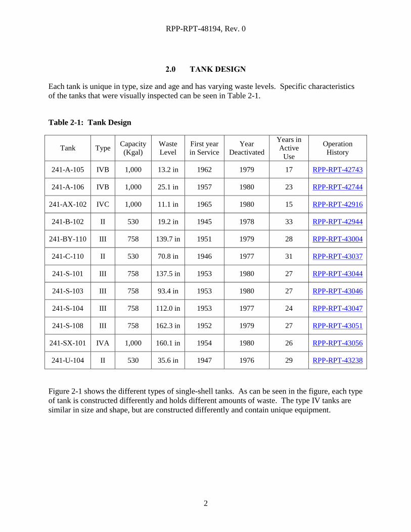
2.0 TANK DESIGN
Each tank is unique in type, size and age and has varying waste levels. Specific characteristics
of the tanks that were visually inspected can be seen in Table 2-1.
Table 2-1: Tank Design
Tank Type Capacity
(Kgal)
Waste
Level
First year
in Service
Year
Deactivated
Years in
Active
Use
Operation
History
241-A-105 IVB 1,000 13.2 in 1962 1979 17 RPP-RPT-42743
241-A-106 IVB 1,000 25.1 in 1957 1980 23 RPP-RPT-42744
241-AX-102 IVC 1,000 11.1 in 1965 1980 15 RPP-RPT-42916
241-B-102 II 530 19.2 in 1945 1978 33 RPP-RPT-42944
241-BY-110 III 758 139.7 in 1951 1979 28 RPP-RPT-43004
241-C-110 II 530 70.8 in 1946 1977 31 RPP-RPT-43037
241-S-101 III 758 137.5 in 1953 1980 27 RPP-RPT-43044
241-S-103 III 758 93.4 in 1953 1980 27 RPP-RPT-43046
241-S-104 III 758 112.0 in 1953 1977 24 RPP-RPT-43047
241-S-108 III 758 162.3 in 1952 1979 27 RPP-RPT-43051
241-SX-101 IVA 1,000 160.1 in 1954 1980 26 RPP-RPT-43056
241-U-104 II 530 35.6 in 1947 1976 29 RPP-RPT-43238
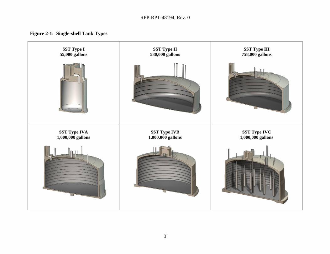
Figure 2-1 shows the different types of single-shell tanks. As can be seen in the figure, each type
of tank is constructed differently and holds different amounts of waste. The type IV tanks are
similar in size and shape, but are constructed differently and contain unique equipment.
RPP-RPT-48194, Rev. 0
3
Figure 2-1: Single-shell Tank Types
SST Type I
55,000 gallons
SST Type II
530,000 gallons
SST Type III
758,000 gallons
SST Type IVA
1,000,000 gallons
SST Type IVB
1,000,000 gallons
SST Type IVC
1,000,000 gallons
RPP-RPT-48194, Rev. 0
4
3.0 SCOPE OF SINGLE-SHELL TANK VISUAL INSPECTION
The SSTs were examined visually for conditions inside the tank (above the waste level) on the
surface of the steel liner and concrete dome using remote video equipment.
Qualified quality control (QC) personnel were briefed on what and where to look at to ensure a
quality inspection was performed to adequately aid the engineering review. Areas of focus were
identified from photographs taken from within the tank in past years and assembled into a work
package.
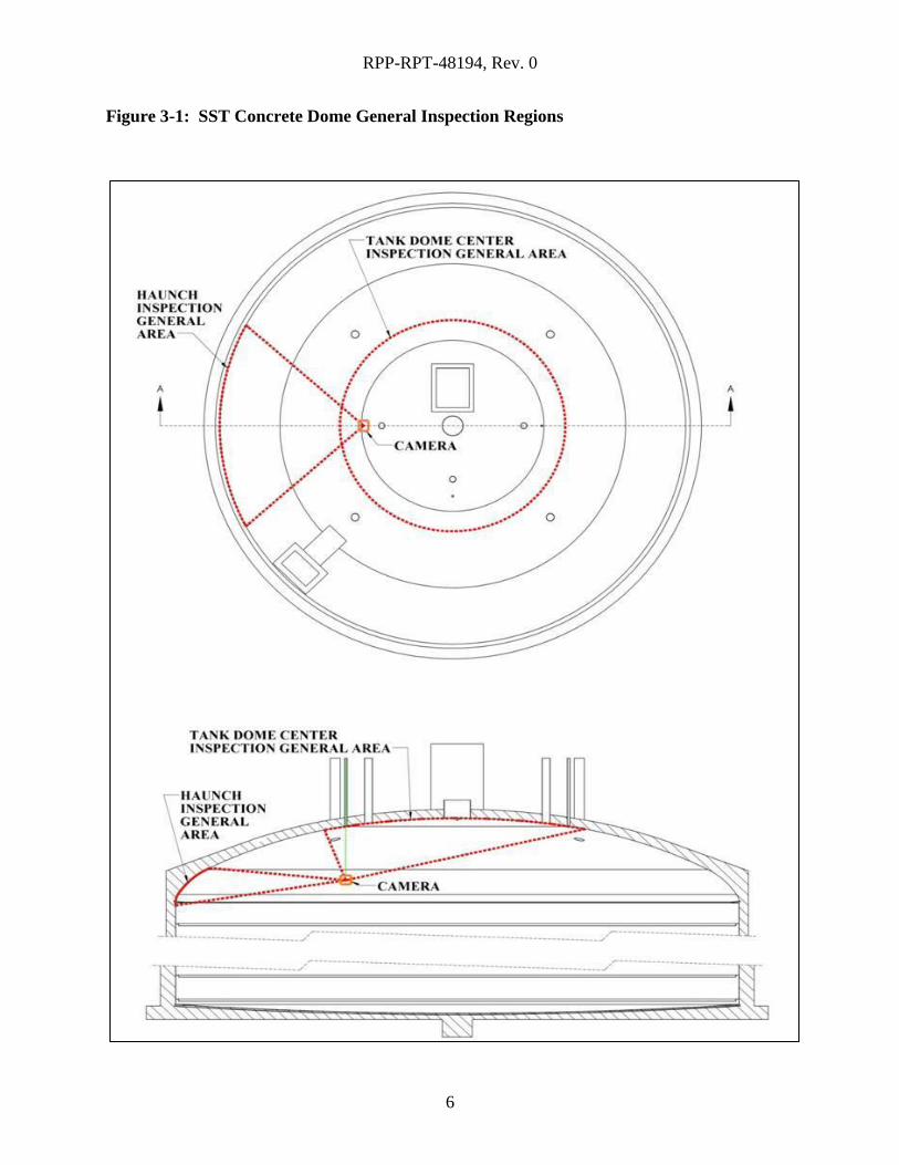
The tank’s interior visual examination was performed through one or two of the tank’s risers.
The combination of the camera system and location of the risers allowed the inspection of the
haunch and center dome region for each SST. The SST inspection criteria are listed in Table
3-1.
The SST visual examinations were compared against previous in-tank photographs and videos to
aid in determining any potential change in specific areas of interest.
RPP-RPT-48194, Rev. 0
5
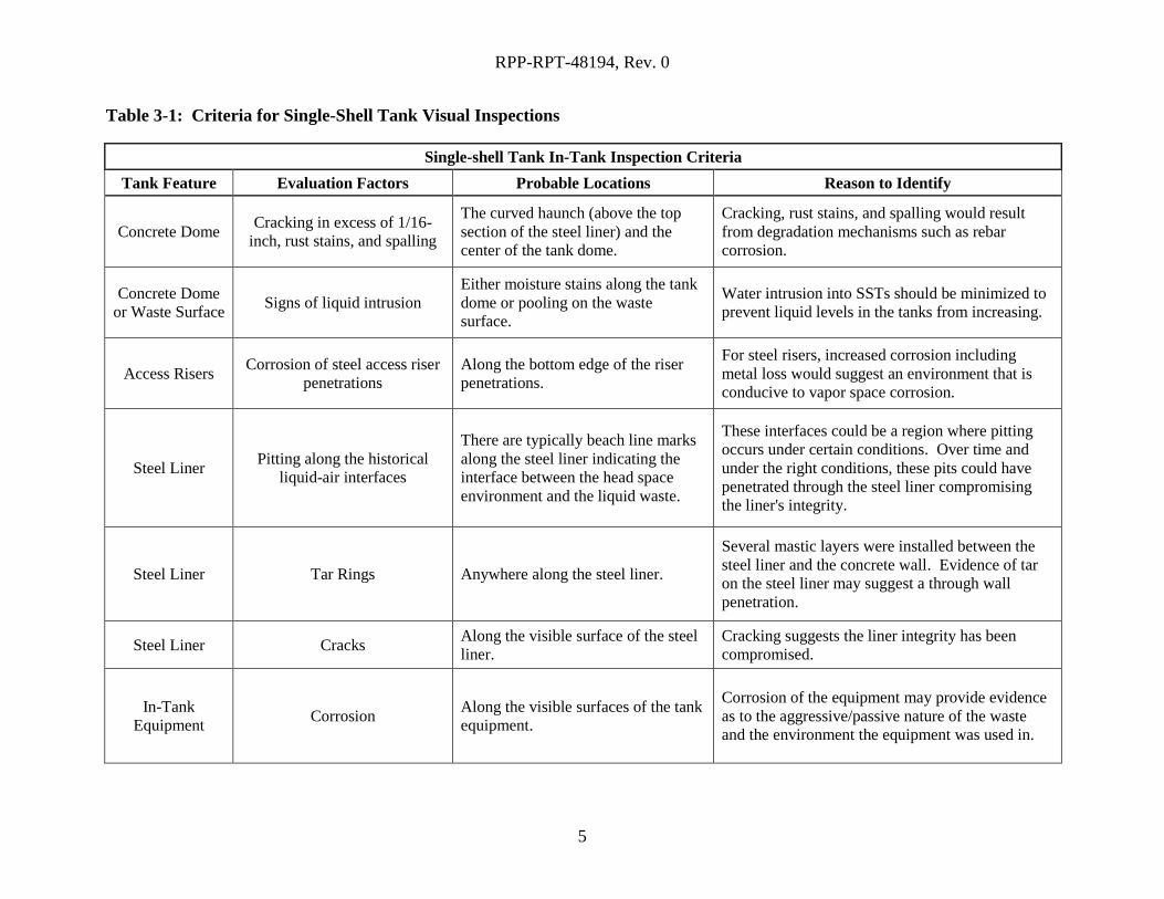
Table 3-1: Criteria for Single-Shell Tank Visual Inspections
Single-shell Tank In-Tank Inspection Criteria
Tank Feature Evaluation Factors Probable Locations Reason to Identify
Concrete Dome Cracking in excess of 1/16-
inch, rust stains, and spalling
The curved haunch (above the top
section of the steel liner) and the
center of the tank dome.
Cracking, rust stains, and spalling would result
from degradation mechanisms such as rebar
corrosion.
Concrete Dome
or Waste Surface Signs of liquid intrusion
Either moisture stains along the tank
dome or pooling on the waste
surface.
Water intrusion into SSTs should be minimized to
prevent liquid levels in the tanks from increasing.
Access Risers Corrosion of steel access riser
penetrations Along the bottom edge of the riser
penetrations.
For steel risers, increased corrosion including
metal loss would suggest an environment that is
conducive to vapor space corrosion.
Steel Liner Pitting along the historical
liquid-air interfaces
There are typically beach line marks
along the steel liner indicating the
interface between the head space
environment and the liquid waste.
These interfaces could be a region where pitting
occurs under certain conditions. Over time and
under the right conditions, these pits could have
penetrated through the steel liner compromising
the liner's integrity.
Steel Liner Tar Rings Anywhere along the steel liner.
Several mastic layers were installed between the
steel liner and the concrete wall. Evidence of tar
on the steel liner may suggest a through wall
penetration.
Steel Liner Cracks Along the visible surface of the steel
liner. Cracking suggests the liner integrity has been
compromised.
In-Tank
Equipment Corrosion
Along the visible surfaces of the tank
equipment.
Corrosion of the equipment may provide evidence
as to the aggressive/passive nature of the waste
and the environment the equipment was used in.
RPP-RPT-48194, Rev. 0
6
Figure 3-1: SST Concrete Dome General Inspection Regions
RPP-RPT-48194, Rev. 0
7
3.1 SINGLE-SHELL TANK VISUAL INSPECTION CRITERIA
Historic visual inspection records of the SST interiors provide examples of anomalies which
current inspections use to help identify areas of interest in other SSTs. These anomalies include
but are not limited to reinforced concrete cracking, spalling, or visible rust stains on the dome,
signs of liquid intrusion, tar rings along the steel liner, and cracks in the steel liner. All of these
visually detectable abnormalities are indicators of various aging mechanisms present in the
specific SST.
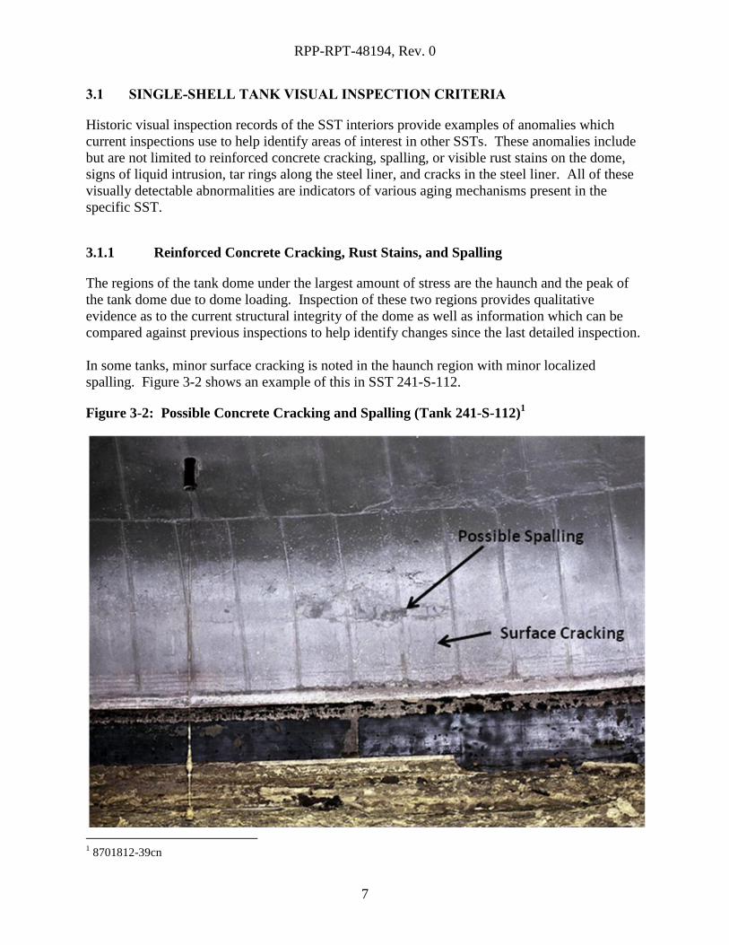
3.1.1 Reinforced Concrete Cracking, Rust Stains, and Spalling
The regions of the tank dome under the largest amount of stress are the haunch and the peak of
the tank dome due to dome loading. Inspection of these two regions provides qualitative
evidence as to the current structural integrity of the dome as well as information which can be
compared against previous inspections to help identify changes since the last detailed inspection.
In some tanks, minor surface cracking is noted in the haunch region with minor localized
spalling. Figure 3-2 shows an example of this in SST 241-S-112.
Figure 3-2: Possible Concrete Cracking and Spalling (Tank 241-S-112)1
1 8701812-39cn
RPP-RPT-48194, Rev. 0
8
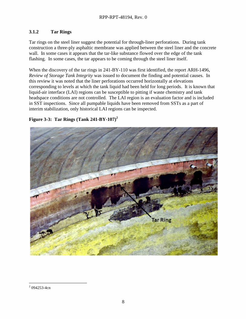
3.1.2 Tar Rings
Tar rings on the steel liner suggest the potential for through-liner perforations. During tank
construction a three-ply asphaltic membrane was applied between the steel liner and the concrete
wall. In some cases it appears that the tar-like substance flowed over the edge of the tank
flashing. In some cases, the tar appears to be coming through the steel liner itself.
When the discovery of the tar rings in 241-BY-110 was first identified, the report ARH-1496,
Review of Storage Tank Integrity was issued to document the finding and potential causes. In
this review it was noted that the liner perforations occurred horizontally at elevations
corresponding to levels at which the tank liquid had been held for long periods. It is known that
liquid-air interface (LAI) regions can be susceptible to pitting if waste chemistry and tank
headspace conditions are not controlled. The LAI region is an evaluation factor and is included
in SST inspections. Since all pumpable liquids have been removed from SSTs as a part of
interim stabilization, only historical LAI regions can be inspected.
Figure 3-3: Tar Rings (Tank 241-BY-107)2
2 094253-4cn
RPP-RPT-48194, Rev. 0
9
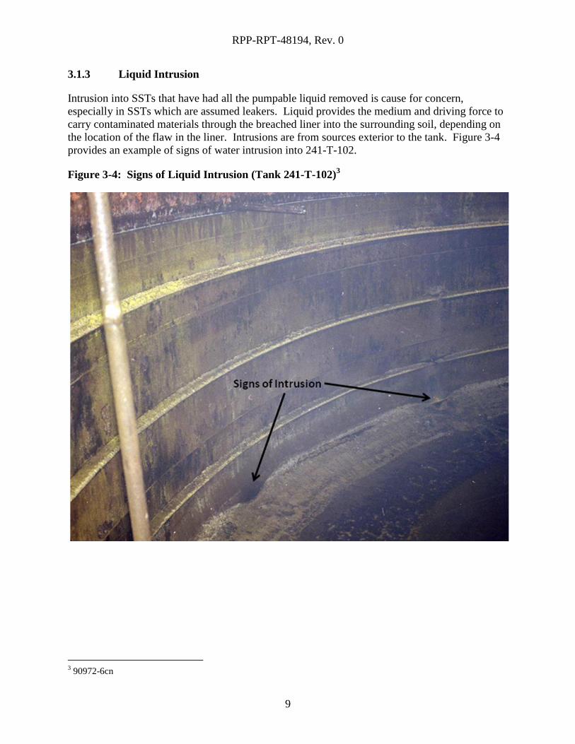
3.1.3 Liquid Intrusion
Intrusion into SSTs that have had all the pumpable liquid removed is cause for concern,
especially in SSTs which are assumed leakers. Liquid provides the medium and driving force to
carry contaminated materials through the breached liner into the surrounding soil, depending on
the location of the flaw in the liner. Intrusions are from sources exterior to the tank. Figure 3-4
provides an example of signs of water intrusion into 241-T-102.
Figure 3-4: Signs of Liquid Intrusion (Tank 241-T-102)3
3 90972-6cn
RPP-RPT-48194, Rev. 0
10
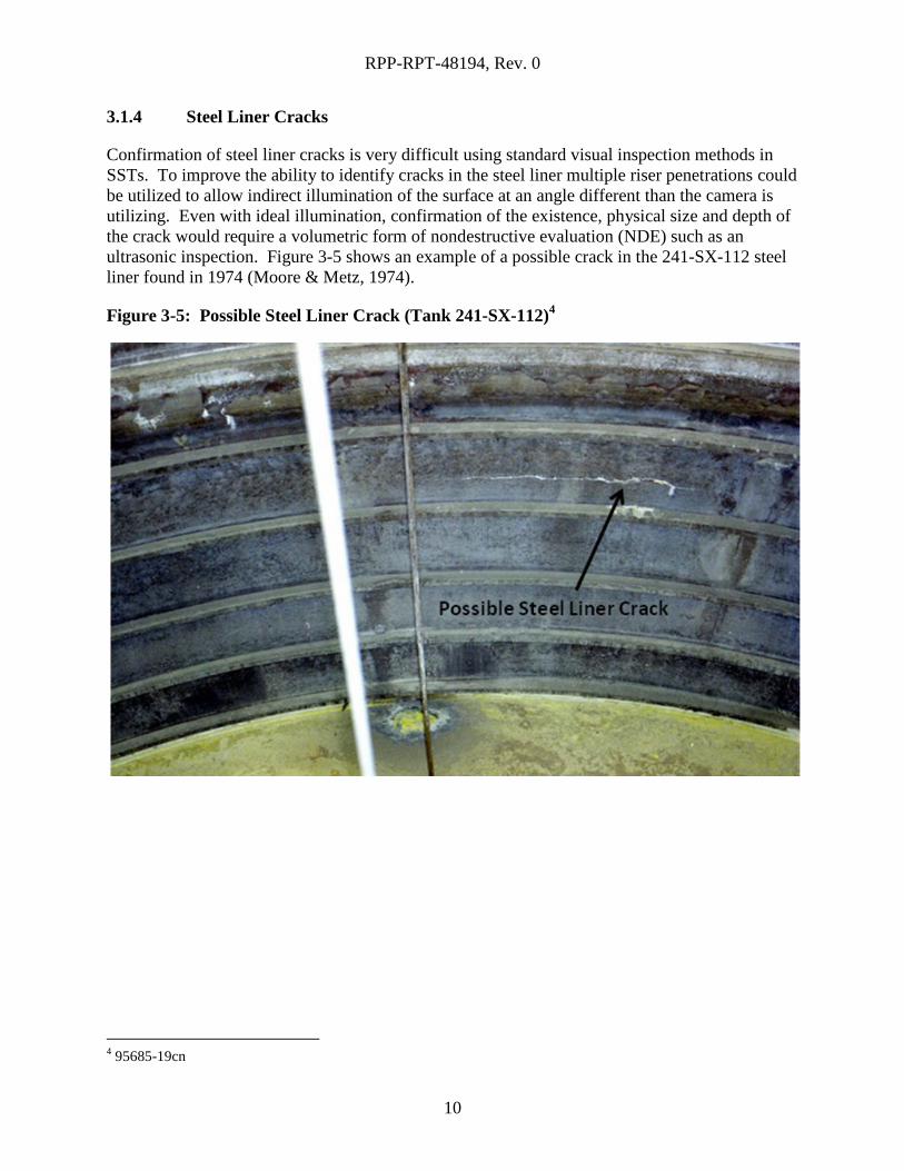
3.1.4 Steel Liner Cracks
Confirmation of steel liner cracks is very difficult using standard visual inspection methods in
SSTs. To improve the ability to identify cracks in the steel liner multiple riser penetrations could
be utilized to allow indirect illumination of the surface at an angle different than the camera is
utilizing. Even with ideal illumination, confirmation of the existence, physical size and depth of
the crack would require a volumetric form of nondestructive evaluation (NDE) such as an
ultrasonic inspection. Figure 3-5 shows an example of a possible crack in the 241-SX-112 steel
liner found in 1974 (Moore & Metz, 1974).
Figure 3-5: Possible Steel Liner Crack (Tank 241-SX-112)4
4 95685-19cn
RPP-RPT-48194, Rev. 0
11
4.0 METHOD OF INSPECTION
Inspections were performed using a camera, a light source and an access riser. A camera was
lowered through a riser into the tank and rotated to make a video recording of the areas of the
tank previously mentioned (Figure 3-1). The videos were then analyzed for visual anomalies.
4.1 INSPECTION EQUIPMENT
Each inspection used a light source to illuminate the tank as well as a camera. The access points
and the illumination intensity in each tank vary and therefore the observable visual detail was
also variable. For example, when the inspection is done from a center riser, all the walls are
about 37.5 feet away. With the same light source, when the inspection is done from a near wall
riser, one side of the tank is 75 feet away. The illumination of the tank and the capability for the
camera to zoom cause these walls to be harder to inspect visually. Table 4-1 displays the
different equipment used for each tank during visual inspections.
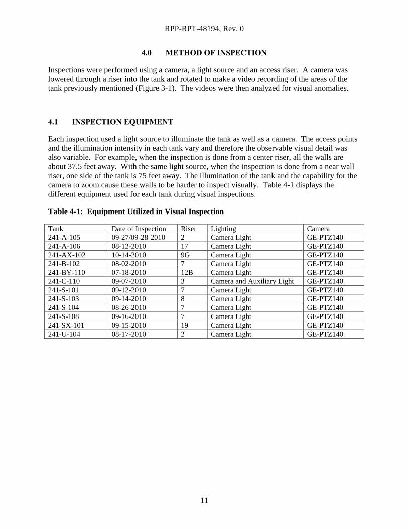
Table 4-1: Equipment Utilized in Visual Inspection
Tank Date of Inspection Riser Lighting Camera
241-A-105 09-27/09-28-2010 2 Camera Light GE-PTZ140
241-A-106 08-12-2010 17 Camera Light GE-PTZ140
241-AX-102 10-14-2010 9G Camera Light GE-PTZ140
241-B-102 08-02-2010 7 Camera Light GE-PTZ140
241-BY-110 07-18-2010 12B Camera Light GE-PTZ140
241-C-110 09-07-2010 3 Camera and Auxiliary Light GE-PTZ140
241-S-101 09-12-2010 7 Camera Light GE-PTZ140
241-S-103 09-14-2010 8 Camera Light GE-PTZ140
241-S-104 08-26-2010 7 Camera Light GE-PTZ140
241-S-108 09-16-2010 7 Camera Light GE-PTZ140
241-SX-101 09-15-2010 19 Camera Light GE-PTZ140
241-U-104 08-17-2010 2 Camera Light GE-PTZ140
RPP-RPT-48194, Rev. 0
12
5.0 TANK 241-A-105
5.1 RESULTS AND CONCLUSION
Tank 241-A-105 was visually inspected on September 27 and 28, 2010. Inspection was
suspended on September 27th
when the camera overheated and resumed on the 28th
. The footage
taken by the camera was carefully reviewed for any visible anomalies on the inside of the tank
(above the waste level) on the surface of the steel liner and concrete dome.
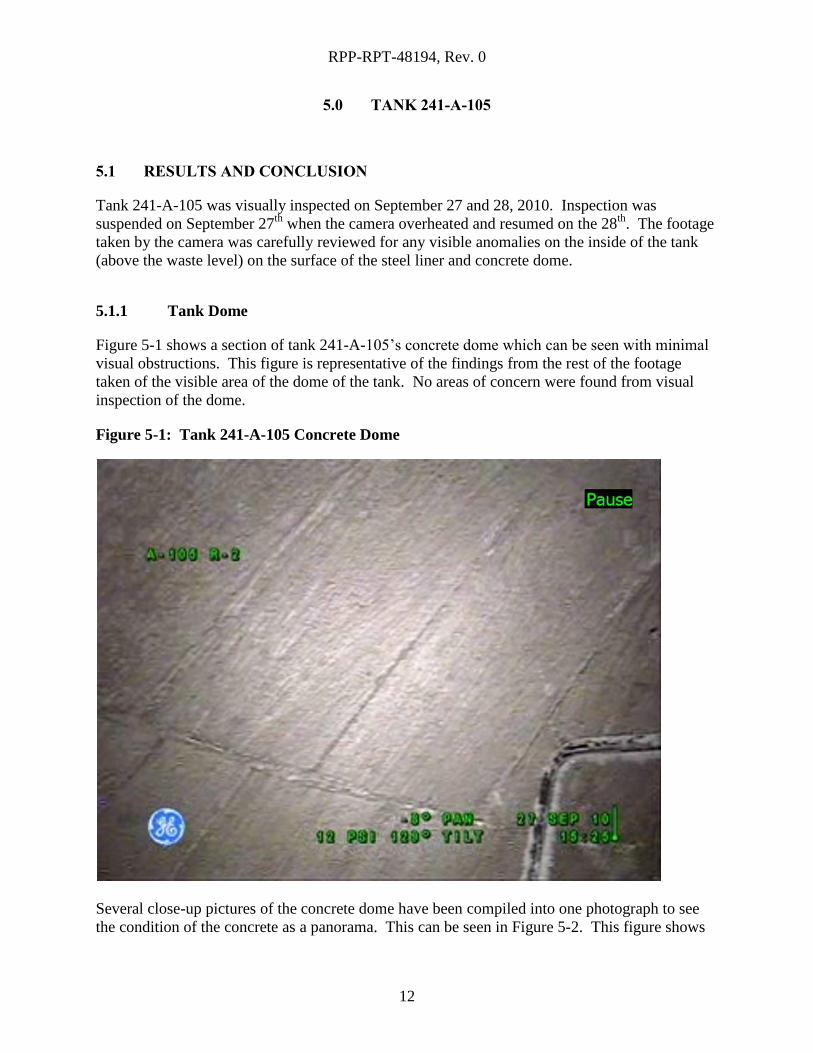
5.1.1 Tank Dome
Figure 5-1 shows a section of tank 241-A-105’s concrete dome which can be seen with minimal
visual obstructions. This figure is representative of the findings from the rest of the footage
taken of the visible area of the dome of the tank. No areas of concern were found from visual
inspection of the dome.
Figure 5-1: Tank 241-A-105 Concrete Dome
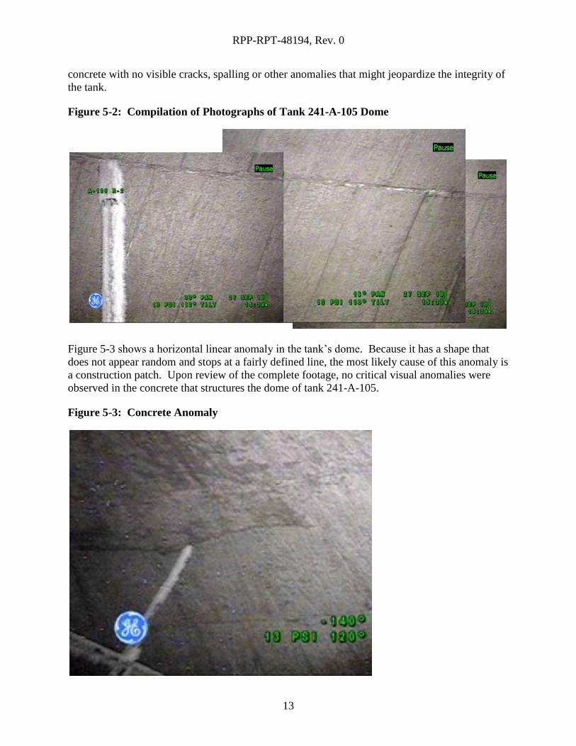
Several close-up pictures of the concrete dome have been compiled into one photograph to see
the condition of the concrete as a panorama. This can be seen in Figure 5-2. This figure shows
RPP-RPT-48194, Rev. 0
13
concrete with no visible cracks, spalling or other anomalies that might jeopardize the integrity of
the tank.
Figure 5-2: Compilation of Photographs of Tank 241-A-105 Dome
Figure 5-3 shows a horizontal linear anomaly in the tank’s dome. Because it has a shape that
does not appear random and stops at a fairly defined line, the most likely cause of this anomaly is
a construction patch. Upon review of the complete footage, no critical visual anomalies were
observed in the concrete that structures the dome of tank 241-A-105.
Figure 5-3: Concrete Anomaly
RPP-RPT-48194, Rev. 0
14
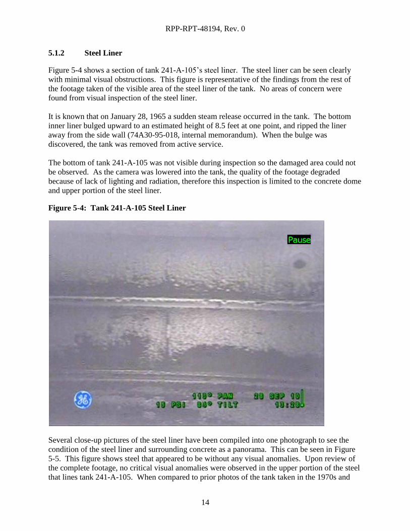
5.1.2 Steel Liner
Figure 5-4 shows a section of tank 241-A-105’s steel liner. The steel liner can be seen clearly
with minimal visual obstructions. This figure is representative of the findings from the rest of
the footage taken of the visible area of the steel liner of the tank. No areas of concern were
found from visual inspection of the steel liner.
It is known that on January 28, 1965 a sudden steam release occurred in the tank. The bottom
inner liner bulged upward to an estimated height of 8.5 feet at one point, and ripped the liner
away from the side wall (74A30-95-018, internal memorandum). When the bulge was
discovered, the tank was removed from active service.
The bottom of tank 241-A-105 was not visible during inspection so the damaged area could not
be observed. As the camera was lowered into the tank, the quality of the footage degraded
because of lack of lighting and radiation, therefore this inspection is limited to the concrete dome
and upper portion of the steel liner.
Figure 5-4: Tank 241-A-105 Steel Liner
Several close-up pictures of the steel liner have been compiled into one photograph to see the
condition of the steel liner and surrounding concrete as a panorama. This can be seen in Figure
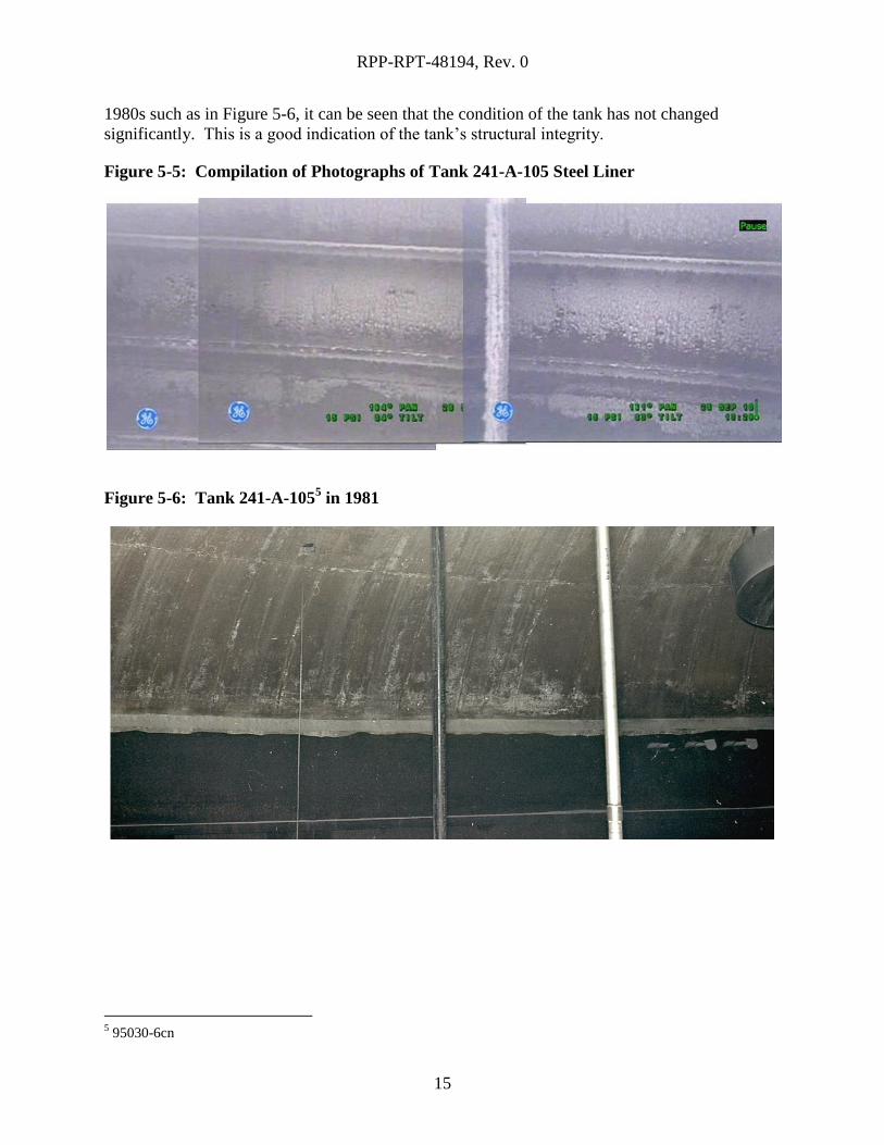
5-5. This figure shows steel that appeared to be without any visual anomalies. Upon review of
the complete footage, no critical visual anomalies were observed in the upper portion of the steel
that lines tank 241-A-105. When compared to prior photos of the tank taken in the 1970s and
RPP-RPT-48194, Rev. 0
15
1980s such as in Figure 5-6, it can be seen that the condition of the tank has not changed
significantly. This is a good indication of the tank’s structural integrity.
Figure 5-5: Compilation of Photographs of Tank 241-A-105 Steel Liner
Figure 5-6: Tank 241-A-1055 in 1981
5 95030-6cn
RPP-RPT-48194, Rev. 0
16
5.1.3 In-Tank Equipment/Risers
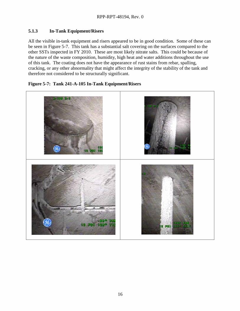
All the visible in-tank equipment and risers appeared to be in good condition. Some of these can
be seen in Figure 5-7. This tank has a substantial salt covering on the surfaces compared to the
other SSTs inspected in FY 2010. These are most likely nitrate salts. This could be because of
the nature of the waste composition, humidity, high heat and water additions throughout the use
of this tank. The coating does not have the appearance of rust stains from rebar, spalling,
cracking, or any other abnormality that might affect the integrity of the stability of the tank and
therefore not considered to be structurally significant.
Figure 5-7: Tank 241-A-105 In-Tank Equipment/Risers
RPP-RPT-48194, Rev. 0
17
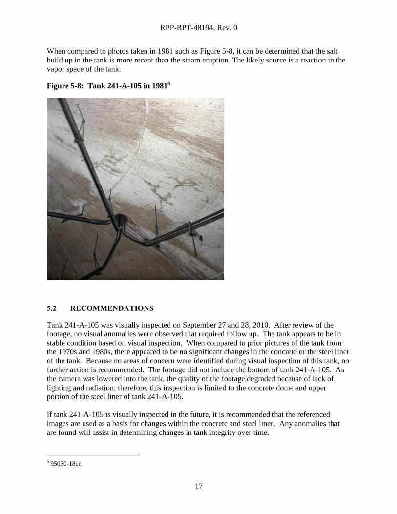
When compared to photos taken in 1981 such as Figure 5-8, it can be determined that the salt
build up in the tank is more recent than the steam eruption. The likely source is a reaction in the
vapor space of the tank.
Figure 5-8: Tank 241-A-105 in 19816
5.2 RECOMMENDATIONS
Tank 241-A-105 was visually inspected on September 27 and 28, 2010. After review of the
footage, no visual anomalies were observed that required follow up. The tank appears to be in
stable condition based on visual inspection. When compared to prior pictures of the tank from
the 1970s and 1980s, there appeared to be no significant changes in the concrete or the steel liner
of the tank. Because no areas of concern were identified during visual inspection of this tank, no
further action is recommended. The footage did not include the bottom of tank 241-A-105. As
the camera was lowered into the tank, the quality of the footage degraded because of lack of
lighting and radiation; therefore, this inspection is limited to the concrete dome and upper
portion of the steel liner of tank 241-A-105.
If tank 241-A-105 is visually inspected in the future, it is recommended that the referenced
images are used as a basis for changes within the concrete and steel liner. Any anomalies that
are found will assist in determining changes in tank integrity over time.
6 95030-18cn
RPP-RPT-48194, Rev. 0
18
6.0 TANK 241-A-106
6.1 RESULTS AND CONCLUSION
Tank 241-A-106 was visually inspected on August 12, 2010. The footage taken by the camera
was carefully reviewed for any visible anomalies on the inside of the tank (above the waste level)
on the surface of the steel liner and concrete dome to identify any areas of concern that would
indicate degradation to the structural integrity of the tank.
6.1.1 Tank Dome
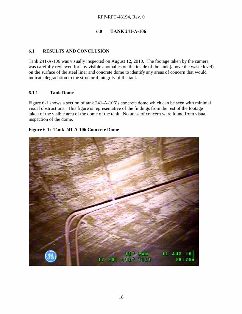
Figure 6-1 shows a section of tank 241-A-106’s concrete dome which can be seen with minimal
visual obstructions. This figure is representative of the findings from the rest of the footage
taken of the visible area of the dome of the tank. No areas of concern were found from visual
inspection of the dome.
Figure 6-1: Tank 241-A-106 Concrete Dome
RPP-RPT-48194, Rev. 0
19
There were some difficulties with the available lighting and the amount of the tank’s dome that
could clearly be visually inspected. However, areas that could clearly be seen appeared to be in
satisfactory condition.
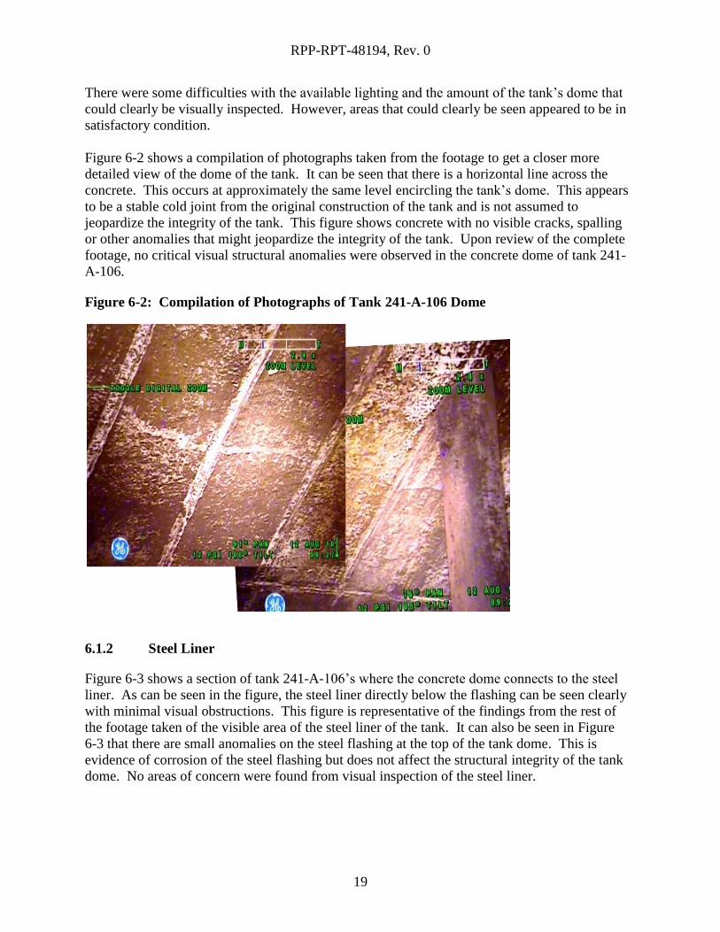
Figure 6-2 shows a compilation of photographs taken from the footage to get a closer more
detailed view of the dome of the tank. It can be seen that there is a horizontal line across the
concrete. This occurs at approximately the same level encircling the tank’s dome. This appears
to be a stable cold joint from the original construction of the tank and is not assumed to
jeopardize the integrity of the tank. This figure shows concrete with no visible cracks, spalling
or other anomalies that might jeopardize the integrity of the tank. Upon review of the complete
footage, no critical visual structural anomalies were observed in the concrete dome of tank 241-
A-106.
Figure 6-2: Compilation of Photographs of Tank 241-A-106 Dome
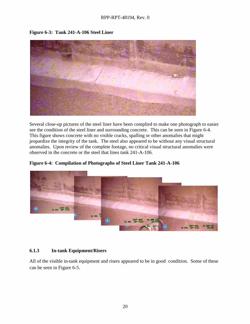
6.1.2 Steel Liner
Figure 6-3 shows a section of tank 241-A-106’s where the concrete dome connects to the steel
liner. As can be seen in the figure, the steel liner directly below the flashing can be seen clearly
with minimal visual obstructions. This figure is representative of the findings from the rest of
the footage taken of the visible area of the steel liner of the tank. It can also be seen in Figure
6-3 that there are small anomalies on the steel flashing at the top of the tank dome. This is
evidence of corrosion of the steel flashing but does not affect the structural integrity of the tank
dome. No areas of concern were found from visual inspection of the steel liner.
RPP-RPT-48194, Rev. 0
20
Figure 6-3: Tank 241-A-106 Steel Liner
Several close-up pictures of the steel liner have been complied to make one photograph to easier
see the condition of the steel liner and surrounding concrete. This can be seen in Figure 6-4.
This figure shows concrete with no visible cracks, spalling or other anomalies that might
jeopardize the integrity of the tank. The steel also appeared to be without any visual structural
anomalies. Upon review of the complete footage, no critical visual structural anomalies were
observed in the concrete or the steel that lines tank 241-A-106.
Figure 6-4: Compilation of Photographs of Steel Liner Tank 241-A-106
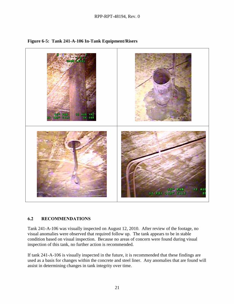
6.1.3 In-tank Equipment/Risers
All of the visible in-tank equipment and risers appeared to be in good condition. Some of these
can be seen in Figure 6-5.
RPP-RPT-48194, Rev. 0
21
Figure 6-5: Tank 241-A-106 In-Tank Equipment/Risers
6.2 RECOMMENDATIONS
Tank 241-A-106 was visually inspected on August 12, 2010. After review of the footage, no
visual anomalies were observed that required follow up. The tank appears to be in stable
condition based on visual inspection. Because no areas of concern were found during visual
inspection of this tank, no further action is recommended.
If tank 241-A-106 is visually inspected in the future, it is recommended that these findings are
used as a basis for changes within the concrete and steel liner. Any anomalies that are found will
assist in determining changes in tank integrity over time.
RPP-RPT-48194, Rev. 0
22
7.0 TANK 241-AX-102
7.1 RESULTS AND CONCLUSION
Tank 241-AX-102 was visually inspected on September 29, 2010. The video quality from this
inspection was not sufficient to determine the condition of the concrete, steel or equipment inside
the tank. The inspection was then performed a second time to attain a higher quality video. The
figures in this section are from the second visual inspection made on October 14, 2010. The
footage taken by the camera was carefully reviewed for any visible anomalies on the inside of
the tank (above the waste level) on the surface of the steel liner and concrete dome to identify
any areas of concern that would indicate degradation to the structural integrity of the tank.
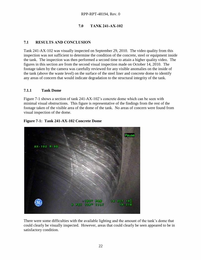
7.1.1 Tank Dome
Figure 7-1 shows a section of tank 241-AX-102’s concrete dome which can be seen with
minimal visual obstructions. This figure is representative of the findings from the rest of the
footage taken of the visible area of the dome of the tank. No areas of concern were found from
visual inspection of the dome.
Figure 7-1: Tank 241-AX-102 Concrete Dome
There were some difficulties with the available lighting and the amount of the tank’s dome that
could clearly be visually inspected. However, areas that could clearly be seen appeared to be in
satisfactory condition.
RPP-RPT-48194, Rev. 0
23
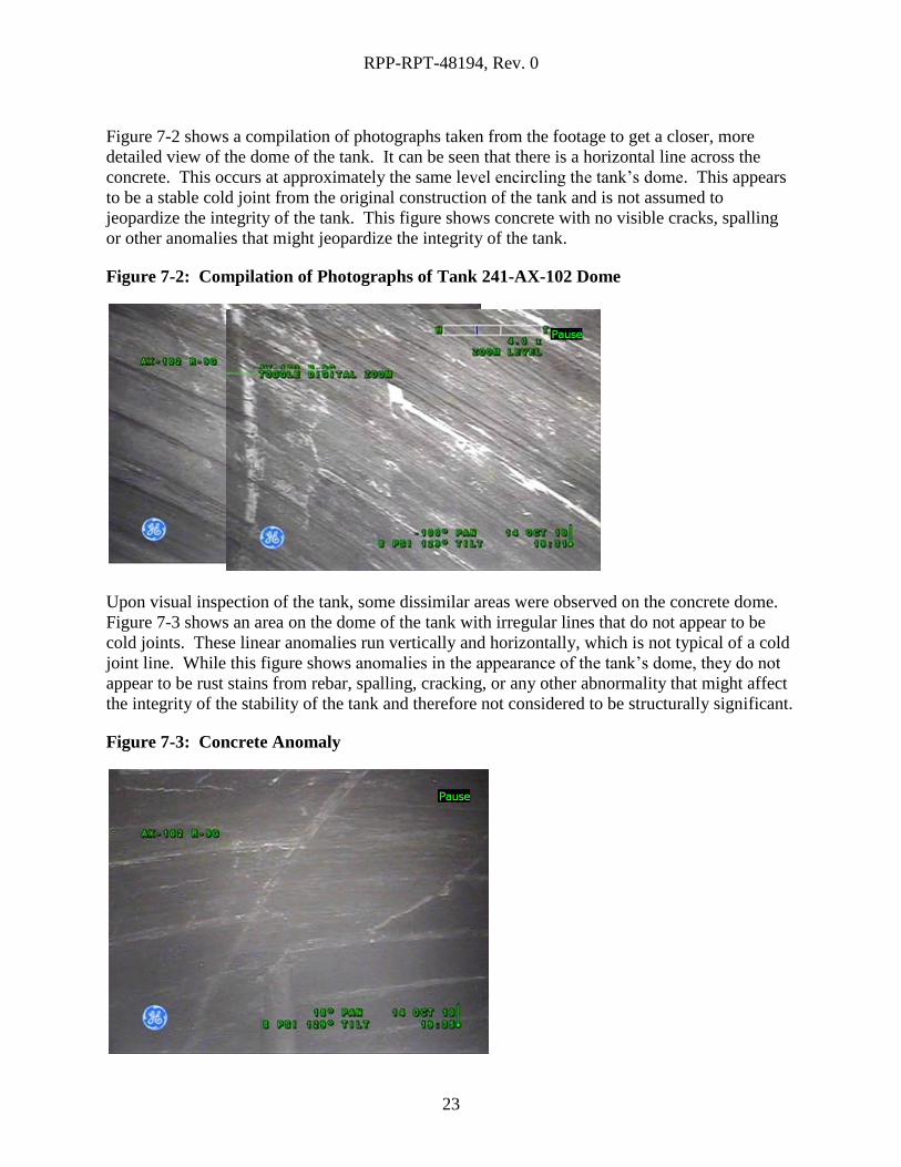
Figure 7-2 shows a compilation of photographs taken from the footage to get a closer, more
detailed view of the dome of the tank. It can be seen that there is a horizontal line across the
concrete. This occurs at approximately the same level encircling the tank’s dome. This appears
to be a stable cold joint from the original construction of the tank and is not assumed to
jeopardize the integrity of the tank. This figure shows concrete with no visible cracks, spalling
or other anomalies that might jeopardize the integrity of the tank.
Figure 7-2: Compilation of Photographs of Tank 241-AX-102 Dome
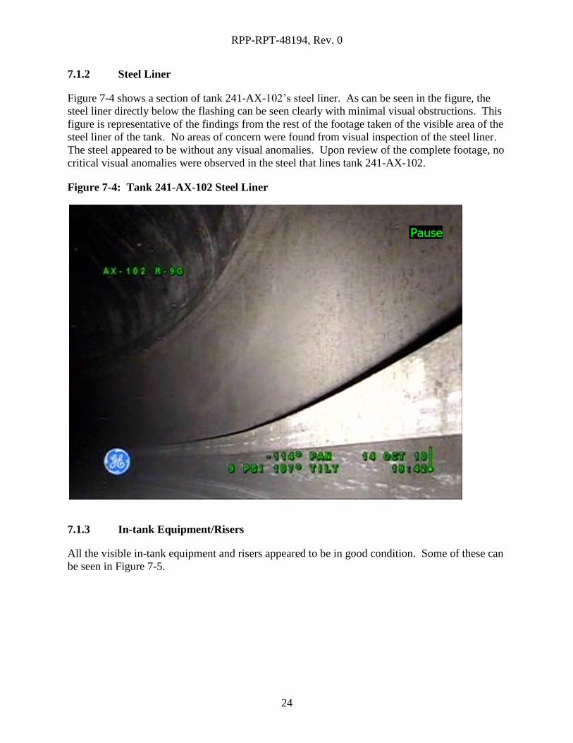
Upon visual inspection of the tank, some dissimilar areas were observed on the concrete dome.
Figure 7-3 shows an area on the dome of the tank with irregular lines that do not appear to be
cold joints. These linear anomalies run vertically and horizontally, which is not typical of a cold
joint line. While this figure shows anomalies in the appearance of the tank’s dome, they do not
appear to be rust stains from rebar, spalling, cracking, or any other abnormality that might affect
the integrity of the stability of the tank and therefore not considered to be structurally significant.
Figure 7-3: Concrete Anomaly
RPP-RPT-48194, Rev. 0
24
7.1.2 Steel Liner
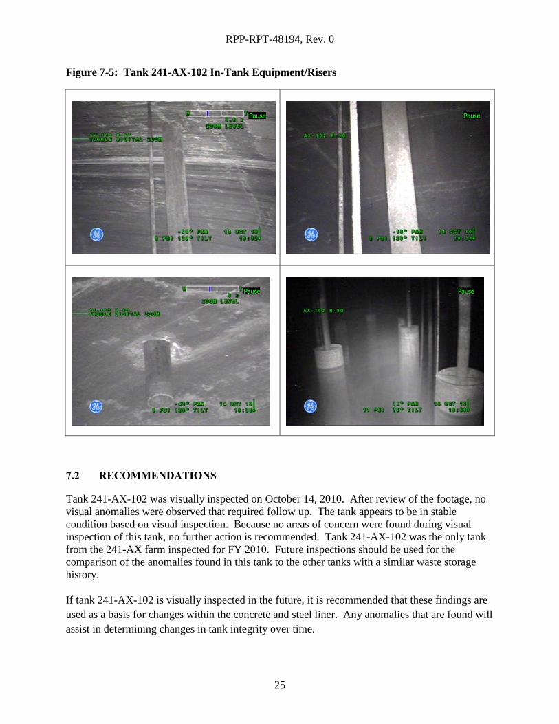
Figure 7-4 shows a section of tank 241-AX-102’s steel liner. As can be seen in the figure, the
steel liner directly below the flashing can be seen clearly with minimal visual obstructions. This
figure is representative of the findings from the rest of the footage taken of the visible area of the
steel liner of the tank. No areas of concern were found from visual inspection of the steel liner.
The steel appeared to be without any visual anomalies. Upon review of the complete footage, no
critical visual anomalies were observed in the steel that lines tank 241-AX-102.
Figure 7-4: Tank 241-AX-102 Steel Liner
7.1.3 In-tank Equipment/Risers
All the visible in-tank equipment and risers appeared to be in good condition. Some of these can
be seen in Figure 7-5.
RPP-RPT-48194, Rev. 0
25
Figure 7-5: Tank 241-AX-102 In-Tank Equipment/Risers
7.2 RECOMMENDATIONS
Tank 241-AX-102 was visually inspected on October 14, 2010. After review of the footage, no
visual anomalies were observed that required follow up. The tank appears to be in stable
condition based on visual inspection. Because no areas of concern were found during visual
inspection of this tank, no further action is recommended. Tank 241-AX-102 was the only tank
from the 241-AX farm inspected for FY 2010. Future inspections should be used for the
comparison of the anomalies found in this tank to the other tanks with a similar waste storage
history.
If tank 241-AX-102 is visually inspected in the future, it is recommended that these findings are
used as a basis for changes within the concrete and steel liner. Any anomalies that are found will
assist in determining changes in tank integrity over time.
RPP-RPT-48194, Rev. 0
26
8.0 TANK 241-B-102
8.1 RESULTS AND CONCLUSION
Tank 241-B-102 was visually inspected on August 2, 2010. The footage taken by the camera
was carefully reviewed for any visible anomalies on the inside of the tank (above the waste level)
on the surface of the steel liner and concrete dome to identify any areas of concern that would
indicate degradation to the structural integrity of the tank.
8.1.1 Tank Dome
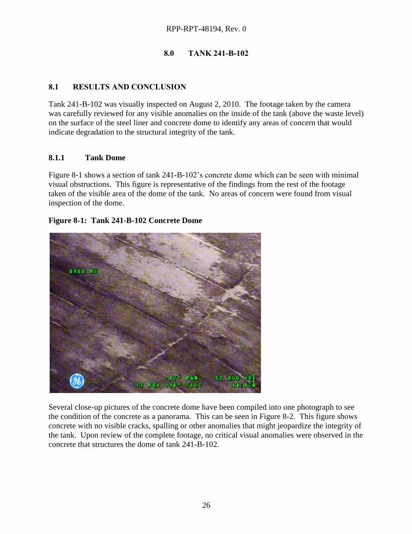
Figure 8-1 shows a section of tank 241-B-102’s concrete dome which can be seen with minimal
visual obstructions. This figure is representative of the findings from the rest of the footage
taken of the visible area of the dome of the tank. No areas of concern were found from visual
inspection of the dome.
Figure 8-1: Tank 241-B-102 Concrete Dome
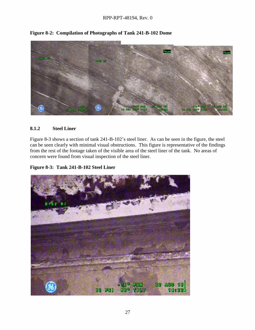
Several close-up pictures of the concrete dome have been compiled into one photograph to see
the condition of the concrete as a panorama. This can be seen in Figure 8-2. This figure shows
concrete with no visible cracks, spalling or other anomalies that might jeopardize the integrity of
the tank. Upon review of the complete footage, no critical visual anomalies were observed in the
concrete that structures the dome of tank 241-B-102.
RPP-RPT-48194, Rev. 0
27
Figure 8-2: Compilation of Photographs of Tank 241-B-102 Dome
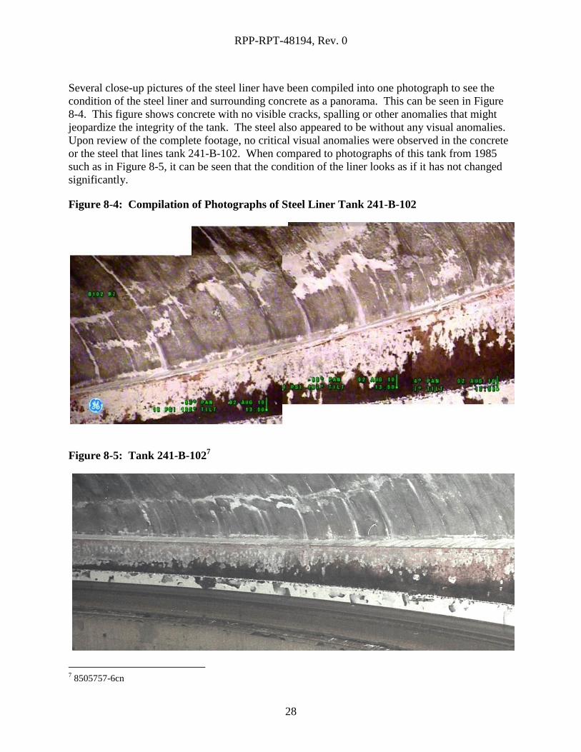
8.1.2 Steel Liner
Figure 8-3 shows a section of tank 241-B-102’s steel liner. As can be seen in the figure, the steel
can be seen clearly with minimal visual obstructions. This figure is representative of the findings
from the rest of the footage taken of the visible area of the steel liner of the tank. No areas of
concern were found from visual inspection of the steel liner.
Figure 8-3: Tank 241-B-102 Steel Liner
RPP-RPT-48194, Rev. 0
28
Several close-up pictures of the steel liner have been compiled into one photograph to see the
condition of the steel liner and surrounding concrete as a panorama. This can be seen in Figure
8-4. This figure shows concrete with no visible cracks, spalling or other anomalies that might
jeopardize the integrity of the tank. The steel also appeared to be without any visual anomalies.
Upon review of the complete footage, no critical visual anomalies were observed in the concrete
or the steel that lines tank 241-B-102. When compared to photographs of this tank from 1985
such as in Figure 8-5, it can be seen that the condition of the liner looks as if it has not changed
significantly.
Figure 8-4: Compilation of Photographs of Steel Liner Tank 241-B-102
Figure 8-5: Tank 241-B-1027
7 8505757-6cn
RPP-RPT-48194, Rev. 0
29
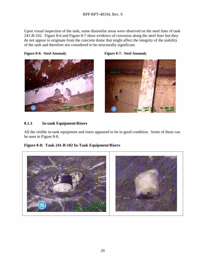
Upon visual inspection of the tank, some dissimilar areas were observed on the steel liner of tank
241-B-102. Figure 8-6 and Figure 8-7 show evidence of corrosion along the steel liner but they
do not appear to originate from the concrete dome that might affect the integrity of the stability
of the tank and therefore not considered to be structurally significant.
Figure 8-6: Steel Anomaly
Figure 8-7: Steel Anomaly
8.1.3 In-tank Equipment/Risers
All the visible in-tank equipment and risers appeared to be in good condition. Some of these can
be seen in Figure 8-8.
Figure 8-8: Tank 241-B-102 In-Tank Equipment/Risers

RPP-RPT-48194, Rev. 0
30
8.2 RECOMMENDATIONS
Tank 241-B-102 was visually inspected on August 2, 2010. After review of the footage, no
visual anomalies were observed that required follow up. The tank appears to be in stable
condition based on visual inspection. When compared to prior pictures of the tank from the
1970s and 1980s, there appeared to be no significant changes in the concrete or the steel liner of
the tank. Because no problems were found during visual inspection of this tank, no further
action is recommended.
If tank 241-B-102 is visually inspected in the future, it is recommended that these findings are
used as a basis for changes within the concrete and steel liner. Any anomalies that are found will
assist in determining changes in tank integrity over time.
RPP-RPT-48194, Rev. 0
31
9.0 TANK 241-BY-110
9.1 RESULTS AND CONCLUSION
Tank 241-BY-110 was visually inspected on July 18, 2010. The footage taken by the camera
was carefully reviewed for any visible anomalies on the inside of the tank (above the waste level)
on the surface of the steel liner and concrete dome to identify any areas of concern that would
indicate degradation to the structural integrity of the tank.
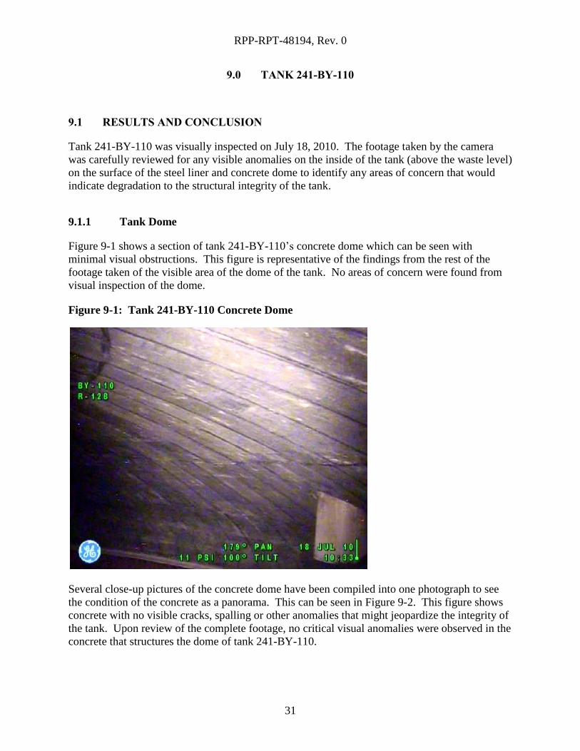
9.1.1 Tank Dome
Figure 9-1 shows a section of tank 241-BY-110’s concrete dome which can be seen with
minimal visual obstructions. This figure is representative of the findings from the rest of the
footage taken of the visible area of the dome of the tank. No areas of concern were found from
visual inspection of the dome.
Figure 9-1: Tank 241-BY-110 Concrete Dome
Several close-up pictures of the concrete dome have been compiled into one photograph to see
the condition of the concrete as a panorama. This can be seen in Figure 9-2. This figure shows
concrete with no visible cracks, spalling or other anomalies that might jeopardize the integrity of
the tank. Upon review of the complete footage, no critical visual anomalies were observed in the
concrete that structures the dome of tank 241-BY-110.
RPP-RPT-48194, Rev. 0
32
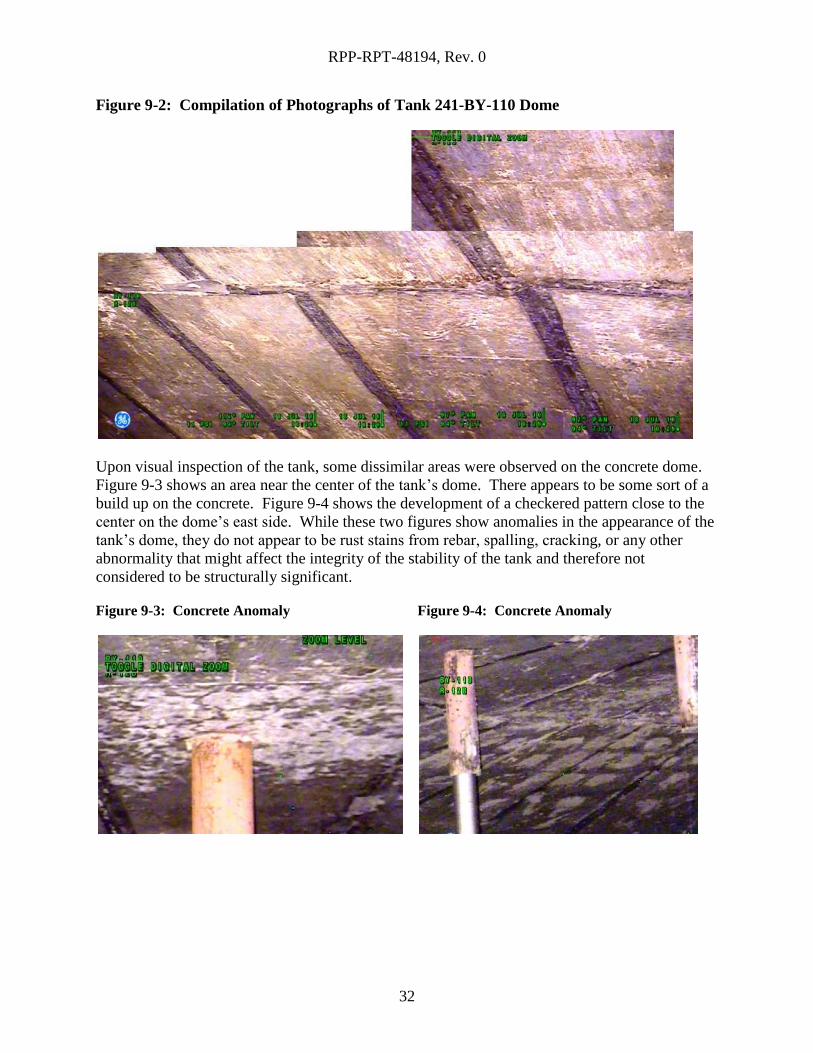
Figure 9-2: Compilation of Photographs of Tank 241-BY-110 Dome
Upon visual inspection of the tank, some dissimilar areas were observed on the concrete dome.
Figure 9-3 shows an area near the center of the tank’s dome. There appears to be some sort of a
build up on the concrete. Figure 9-4 shows the development of a checkered pattern close to the
center on the dome’s east side. While these two figures show anomalies in the appearance of the
tank’s dome, they do not appear to be rust stains from rebar, spalling, cracking, or any other
abnormality that might affect the integrity of the stability of the tank and therefore not
considered to be structurally significant.
Figure 9-3: Concrete Anomaly
Figure 9-4: Concrete Anomaly
RPP-RPT-48194, Rev. 0
33
9.1.2 Steel Liner
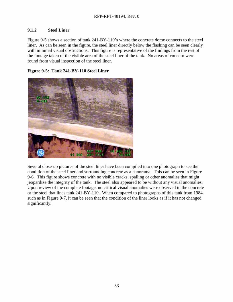
Figure 9-5 shows a section of tank 241-BY-110’s where the concrete dome connects to the steel
liner. As can be seen in the figure, the steel liner directly below the flashing can be seen clearly
with minimal visual obstructions. This figure is representative of the findings from the rest of
the footage taken of the visible area of the steel liner of the tank. No areas of concern were
found from visual inspection of the steel liner.
Figure 9-5: Tank 241-BY-110 Steel Liner
Several close-up pictures of the steel liner have been compiled into one photograph to see the
condition of the steel liner and surrounding concrete as a panorama. This can be seen in Figure
9-6. This figure shows concrete with no visible cracks, spalling or other anomalies that might
jeopardize the integrity of the tank. The steel also appeared to be without any visual anomalies.
Upon review of the complete footage, no critical visual anomalies were observed in the concrete
or the steel that lines tank 241-BY-110. When compared to photographs of this tank from 1984
such as in Figure 9-7, it can be seen that the condition of the liner looks as if it has not changed
significantly.
RPP-RPT-48194, Rev. 0
34
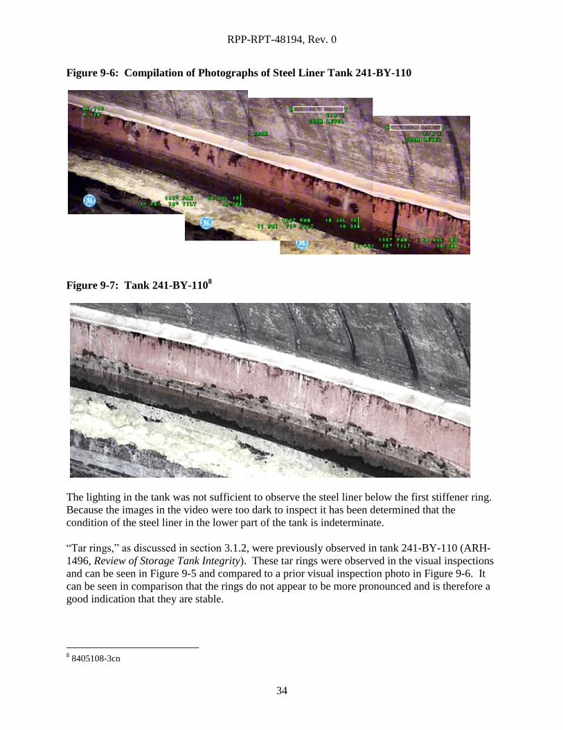
Figure 9-6: Compilation of Photographs of Steel Liner Tank 241-BY-110
Figure 9-7: Tank 241-BY-1108
The lighting in the tank was not sufficient to observe the steel liner below the first stiffener ring.
Because the images in the video were too dark to inspect it has been determined that the
condition of the steel liner in the lower part of the tank is indeterminate.
“Tar rings,” as discussed in section 3.1.2, were previously observed in tank 241-BY-110 (ARH-
1496, Review of Storage Tank Integrity). These tar rings were observed in the visual inspections
and can be seen in Figure 9-5 and compared to a prior visual inspection photo in Figure 9-6. It
can be seen in comparison that the rings do not appear to be more pronounced and is therefore a
good indication that they are stable.
8 8405108-3cn
RPP-RPT-48194, Rev. 0
35
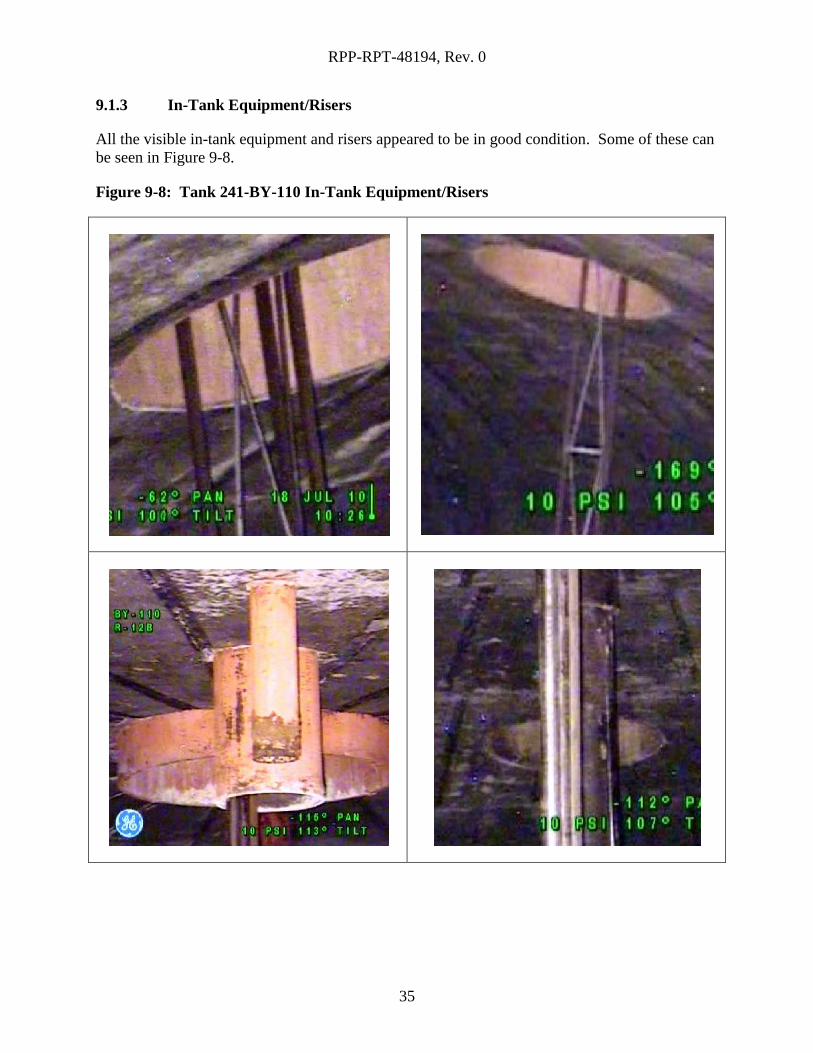
9.1.3 In-Tank Equipment/Risers
All the visible in-tank equipment and risers appeared to be in good condition. Some of these can
be seen in Figure 9-8.
Figure 9-8: Tank 241-BY-110 In-Tank Equipment/Risers
RPP-RPT-48194, Rev. 0
36
9.2 RECOMMENDATIONS
Tank 241-BY-110 was visually inspected on July 18, 2010. After review of the footage, no
visual anomalies were observed that required follow up. The tank appears to be in stable
condition based on visual inspection. When compared to prior pictures of the tank from the
1970s and 1980s, there appeared to be no significant changes in the concrete or the steel liner of
the tank. Because no problems were found during visual inspection of this tank, no further
action is recommended.
If tank 241-BY-110 is visually inspected in the future, it is recommended that these findings are
used as a basis for changes within the concrete and steel liner. Any anomalies that are found will
assist in determining changes in tank integrity over time.
RPP-RPT-48194, Rev. 0
37
10.0 TANK 241-C-110
10.1 RESULTS AND CONCLUSION
Tank 241-C-110 was visually inspected on September 7, 2010. The footage taken by the camera
was carefully reviewed for any visible anomalies on the inside of the tank (above the waste level)
on the surface of the steel liner and concrete dome to identify any areas of concern that would
indicate degradation to the structural integrity of the tank.
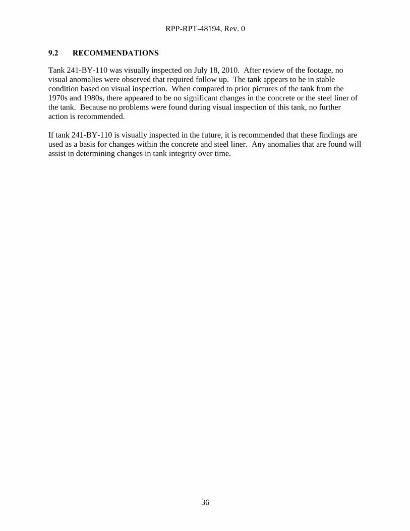
10.1.1 Tank Dome
Figure 10-1 shows a section of tank 241-C-110’s concrete dome which can be seen with minimal
visual obstructions. This figure is representative of the findings from the rest of the footage
taken of the visible area of the dome of the tank. No areas of concern were found from visual
inspection of the dome.
Figure 10-1: Tank 241-C-110 Concrete Dome
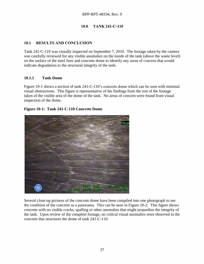
Several close-up pictures of the concrete dome have been compiled into one photograph to see
the condition of the concrete as a panorama. This can be seen in Figure 10-2. This figure shows
concrete with no visible cracks, spalling or other anomalies that might jeopardize the integrity of
the tank. Upon review of the complete footage, no critical visual anomalies were observed in the
concrete that structures the dome of tank 241-C-110.
RPP-RPT-48194, Rev. 0
38
Figure 10-2: Compilation of Photographs of Tank 241-C-110 Dome
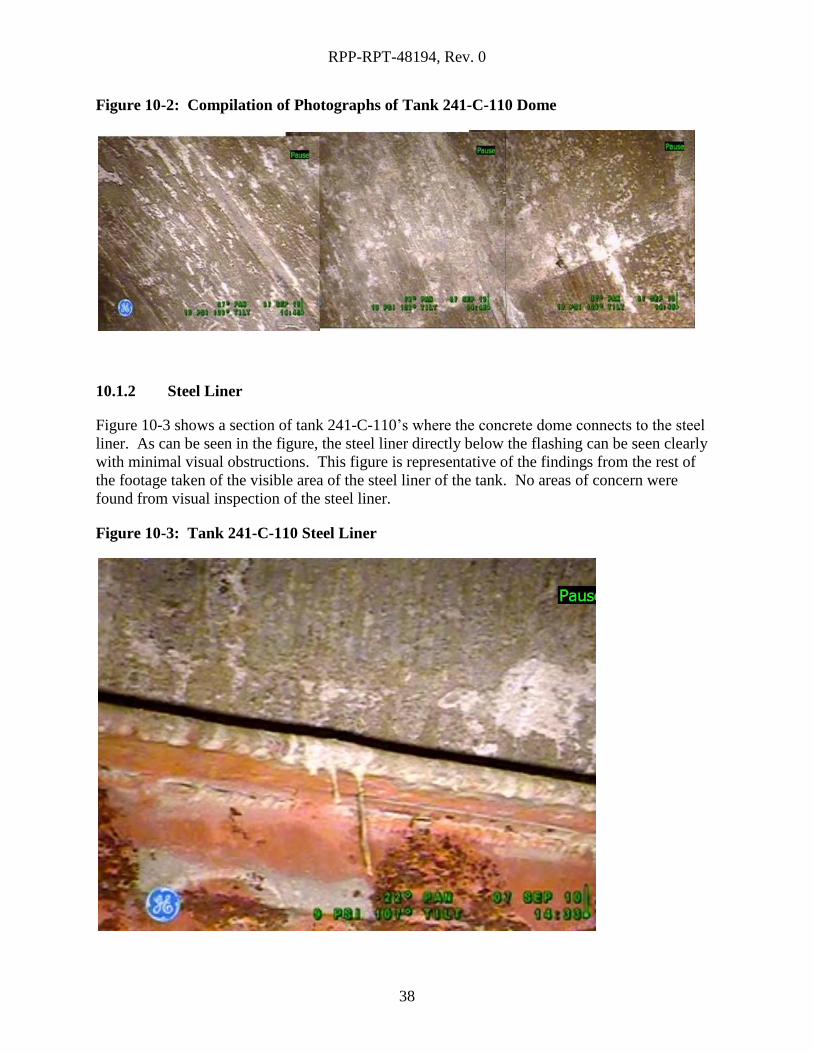
10.1.2 Steel Liner
Figure 10-3 shows a section of tank 241-C-110’s where the concrete dome connects to the steel
liner. As can be seen in the figure, the steel liner directly below the flashing can be seen clearly
with minimal visual obstructions. This figure is representative of the findings from the rest of
the footage taken of the visible area of the steel liner of the tank. No areas of concern were
found from visual inspection of the steel liner.
Figure 10-3: Tank 241-C-110 Steel Liner
RPP-RPT-48194, Rev. 0
39
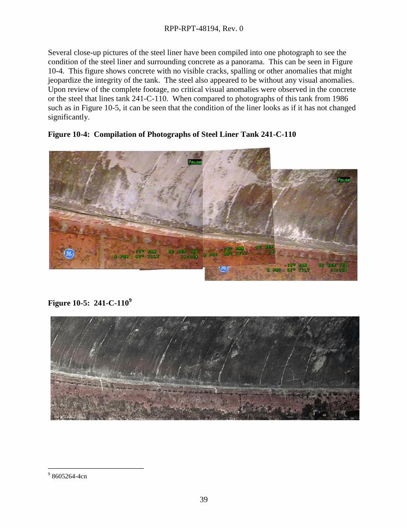
Several close-up pictures of the steel liner have been compiled into one photograph to see the
condition of the steel liner and surrounding concrete as a panorama. This can be seen in Figure
10-4. This figure shows concrete with no visible cracks, spalling or other anomalies that might
jeopardize the integrity of the tank. The steel also appeared to be without any visual anomalies.
Upon review of the complete footage, no critical visual anomalies were observed in the concrete
or the steel that lines tank 241-C-110. When compared to photographs of this tank from 1986
such as in Figure 10-5, it can be seen that the condition of the liner looks as if it has not changed
significantly.
Figure 10-4: Compilation of Photographs of Steel Liner Tank 241-C-110
Figure 10-5: 241-C-1109
9 8605264-4cn
RPP-RPT-48194, Rev. 0
40
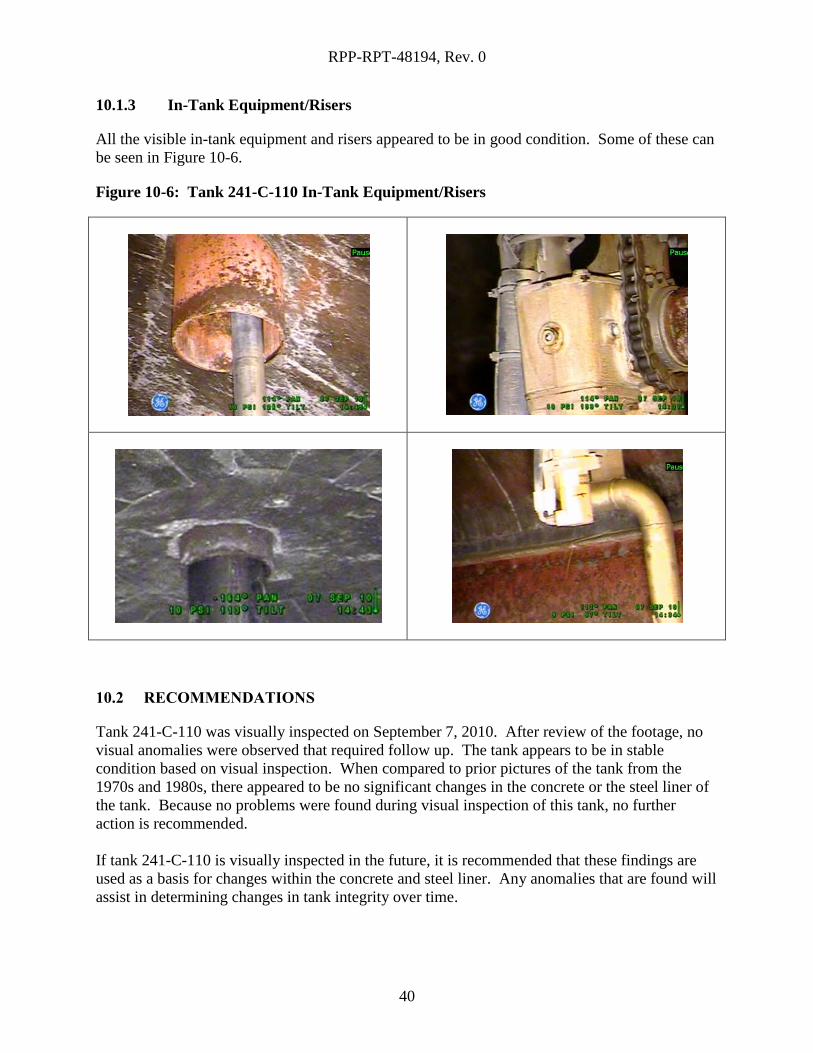
10.1.3 In-Tank Equipment/Risers
All the visible in-tank equipment and risers appeared to be in good condition. Some of these can
be seen in Figure 10-6.
Figure 10-6: Tank 241-C-110 In-Tank Equipment/Risers
10.2 RECOMMENDATIONS
Tank 241-C-110 was visually inspected on September 7, 2010. After review of the footage, no
visual anomalies were observed that required follow up. The tank appears to be in stable
condition based on visual inspection. When compared to prior pictures of the tank from the
1970s and 1980s, there appeared to be no significant changes in the concrete or the steel liner of
the tank. Because no problems were found during visual inspection of this tank, no further
action is recommended.
If tank 241-C-110 is visually inspected in the future, it is recommended that these findings are
used as a basis for changes within the concrete and steel liner. Any anomalies that are found will
assist in determining changes in tank integrity over time.
RPP-RPT-48194, Rev. 0
41
11.0 TANK 241-S-101
11.1 RESULTS AND CONCLUSION
Tank 241-S-101 was visually inspected on September 21, 2010. The footage taken by the
camera was carefully reviewed for any visible anomalies on the inside of the tank (above the
waste level) on the surface of the steel liner and concrete dome to identify any areas of concern
that would indicate degradation to the tank’s structural integrity.
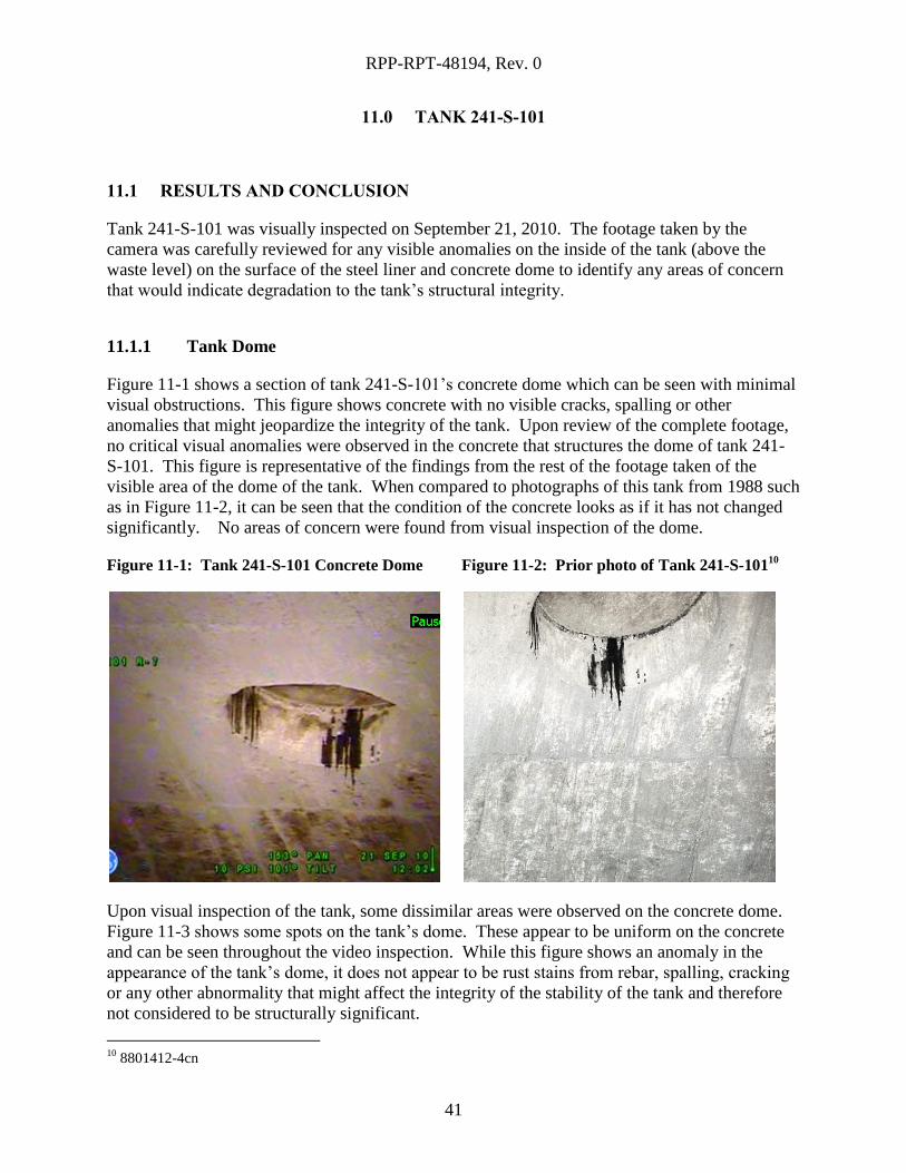
11.1.1 Tank Dome
Figure 11-1 shows a section of tank 241-S-101’s concrete dome which can be seen with minimal
visual obstructions. This figure shows concrete with no visible cracks, spalling or other
anomalies that might jeopardize the integrity of the tank. Upon review of the complete footage,
no critical visual anomalies were observed in the concrete that structures the dome of tank 241-
S-101. This figure is representative of the findings from the rest of the footage taken of the
visible area of the dome of the tank. When compared to photographs of this tank from 1988 such
as in Figure 11-2, it can be seen that the condition of the concrete looks as if it has not changed
significantly. No areas of concern were found from visual inspection of the dome.
Figure 11-1: Tank 241-S-101 Concrete Dome
Figure 11-2: Prior photo of Tank 241-S-10110
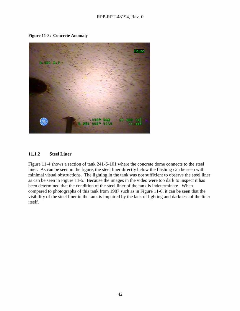
Upon visual inspection of the tank, some dissimilar areas were observed on the concrete dome.
Figure 11-3 shows some spots on the tank’s dome. These appear to be uniform on the concrete
and can be seen throughout the video inspection. While this figure shows an anomaly in the
appearance of the tank’s dome, it does not appear to be rust stains from rebar, spalling, cracking
or any other abnormality that might affect the integrity of the stability of the tank and therefore
not considered to be structurally significant.
10
8801412-4cn
RPP-RPT-48194, Rev. 0
42
Figure 11-3: Concrete Anomaly
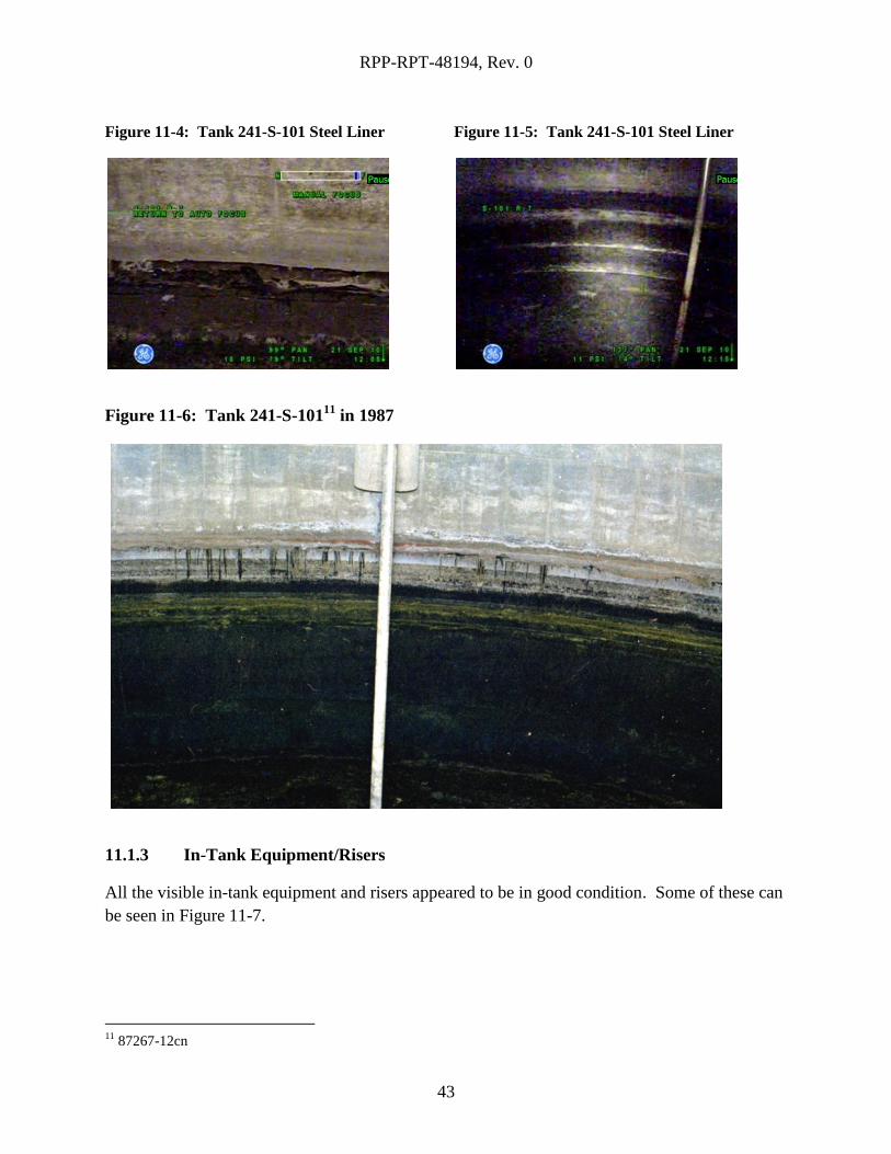
11.1.2 Steel Liner
Figure 11-4 shows a section of tank 241-S-101 where the concrete dome connects to the steel
liner. As can be seen in the figure, the steel liner directly below the flashing can be seen with
minimal visual obstructions. The lighting in the tank was not sufficient to observe the steel liner
as can be seen in Figure 11-5. Because the images in the video were too dark to inspect it has
been determined that the condition of the steel liner of the tank is indeterminate. When
compared to photographs of this tank from 1987 such as in Figure 11-6, it can be seen that the
visibility of the steel liner in the tank is impaired by the lack of lighting and darkness of the liner
itself.
RPP-RPT-48194, Rev. 0
43
Figure 11-4: Tank 241-S-101 Steel Liner
Figure 11-5: Tank 241-S-101 Steel Liner
Figure 11-6: Tank 241-S-10111
in 1987
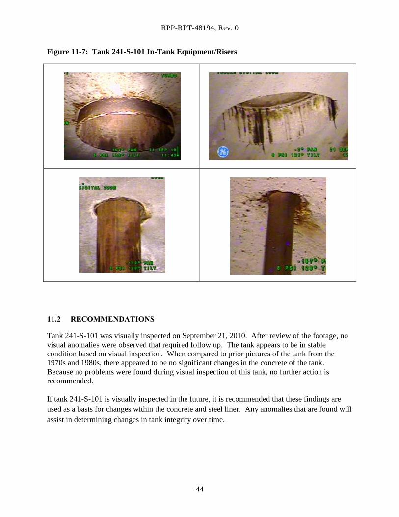
11.1.3 In-Tank Equipment/Risers
All the visible in-tank equipment and risers appeared to be in good condition. Some of these can
be seen in Figure 11-7.
11
87267-12cn
RPP-RPT-48194, Rev. 0
44
Figure 11-7: Tank 241-S-101 In-Tank Equipment/Risers
11.2 RECOMMENDATIONS
Tank 241-S-101 was visually inspected on September 21, 2010. After review of the footage, no
visual anomalies were observed that required follow up. The tank appears to be in stable
condition based on visual inspection. When compared to prior pictures of the tank from the
1970s and 1980s, there appeared to be no significant changes in the concrete of the tank.
Because no problems were found during visual inspection of this tank, no further action is
recommended.
If tank 241-S-101 is visually inspected in the future, it is recommended that these findings are
used as a basis for changes within the concrete and steel liner. Any anomalies that are found will
assist in determining changes in tank integrity over time.
RPP-RPT-48194, Rev. 0
45
12.0 TANK 241-S-103
12.1 RESULTS AND CONCLUSION
Tank 241-S-103 was visually inspected on September 14, 2010. The footage taken by the
camera was carefully reviewed for any visible anomalies on the inside of the tank (above the
waste level) on the surface of the steel liner and concrete dome to identify any areas of concern
that would indicate degradation to the structural integrity of the tank.
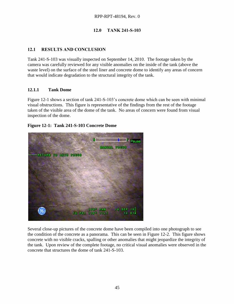
12.1.1 Tank Dome
Figure 12-1 shows a section of tank 241-S-103’s concrete dome which can be seen with minimal
visual obstructions. This figure is representative of the findings from the rest of the footage
taken of the visible area of the dome of the tank. No areas of concern were found from visual
inspection of the dome.
Figure 12-1: Tank 241-S-103 Concrete Dome
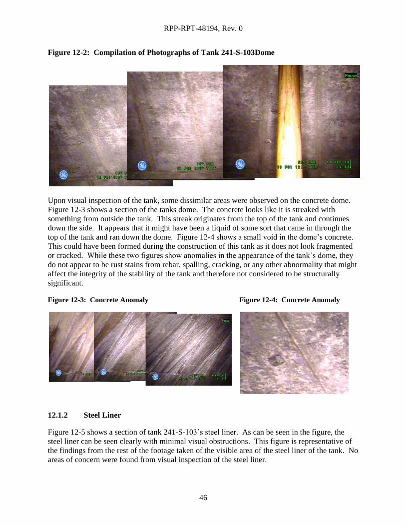
Several close-up pictures of the concrete dome have been compiled into one photograph to see
the condition of the concrete as a panorama. This can be seen in Figure 12-2. This figure shows
concrete with no visible cracks, spalling or other anomalies that might jeopardize the integrity of
the tank. Upon review of the complete footage, no critical visual anomalies were observed in the
concrete that structures the dome of tank 241-S-103.
RPP-RPT-48194, Rev. 0
46
Figure 12-2: Compilation of Photographs of Tank 241-S-103Dome
Upon visual inspection of the tank, some dissimilar areas were observed on the concrete dome.
Figure 12-3 shows a section of the tanks dome. The concrete looks like it is streaked with
something from outside the tank. This streak originates from the top of the tank and continues
down the side. It appears that it might have been a liquid of some sort that came in through the
top of the tank and ran down the dome. Figure 12-4 shows a small void in the dome’s concrete.
This could have been formed during the construction of this tank as it does not look fragmented
or cracked. While these two figures show anomalies in the appearance of the tank’s dome, they
do not appear to be rust stains from rebar, spalling, cracking, or any other abnormality that might
affect the integrity of the stability of the tank and therefore not considered to be structurally
significant.
Figure 12-3: Concrete Anomaly
Figure 12-4: Concrete Anomaly
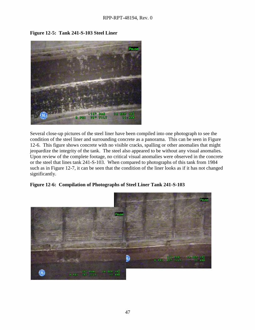
12.1.2 Steel Liner
Figure 12-5 shows a section of tank 241-S-103’s steel liner. As can be seen in the figure, the
steel liner can be seen clearly with minimal visual obstructions. This figure is representative of
the findings from the rest of the footage taken of the visible area of the steel liner of the tank. No
areas of concern were found from visual inspection of the steel liner.
RPP-RPT-48194, Rev. 0
47
Figure 12-5: Tank 241-S-103 Steel Liner
Several close-up pictures of the steel liner have been compiled into one photograph to see the
condition of the steel liner and surrounding concrete as a panorama. This can be seen in Figure
12-6. This figure shows concrete with no visible cracks, spalling or other anomalies that might
jeopardize the integrity of the tank. The steel also appeared to be without any visual anomalies.
Upon review of the complete footage, no critical visual anomalies were observed in the concrete
or the steel that lines tank 241-S-103. When compared to photographs of this tank from 1984
such as in Figure 12-7, it can be seen that the condition of the liner looks as if it has not changed
significantly.
Figure 12-6: Compilation of Photographs of Steel Liner Tank 241-S-103
RPP-RPT-48194, Rev. 0
48
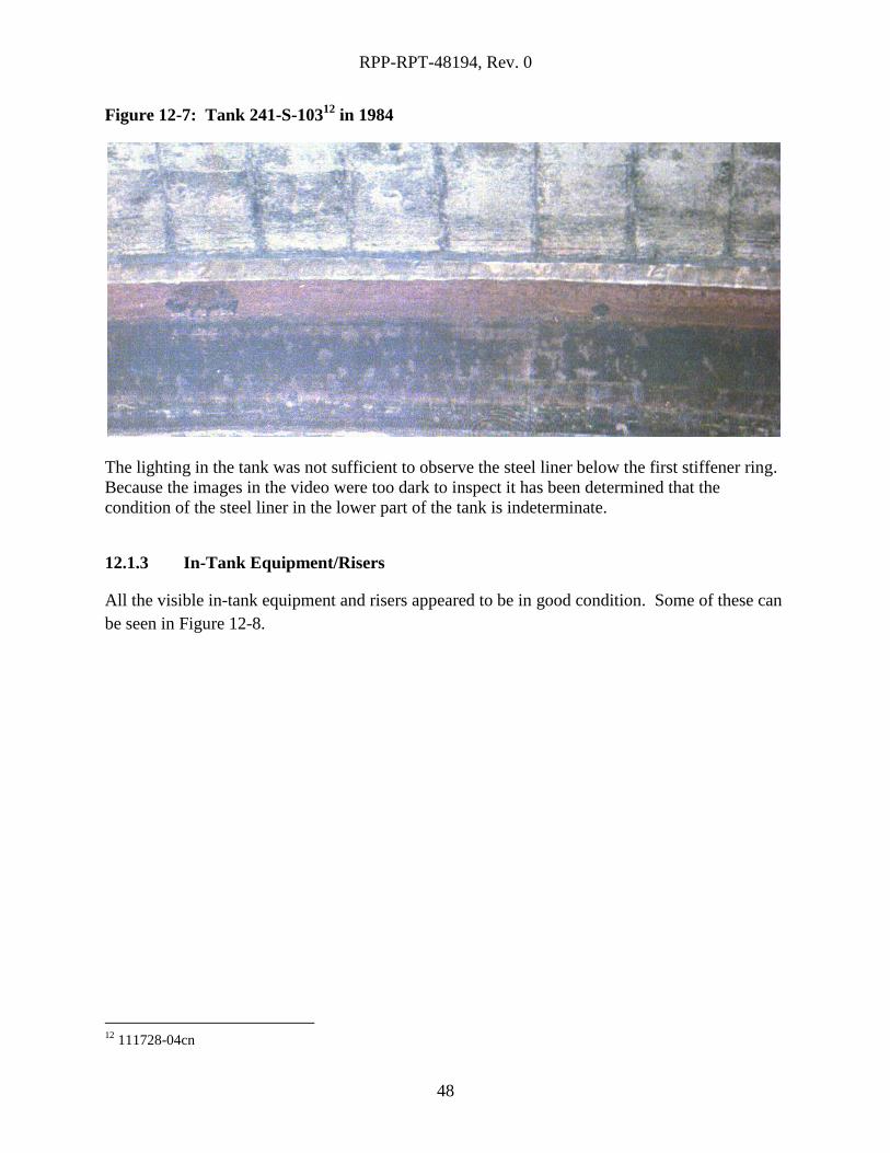
Figure 12-7: Tank 241-S-10312
in 1984
The lighting in the tank was not sufficient to observe the steel liner below the first stiffener ring.
Because the images in the video were too dark to inspect it has been determined that the
condition of the steel liner in the lower part of the tank is indeterminate.
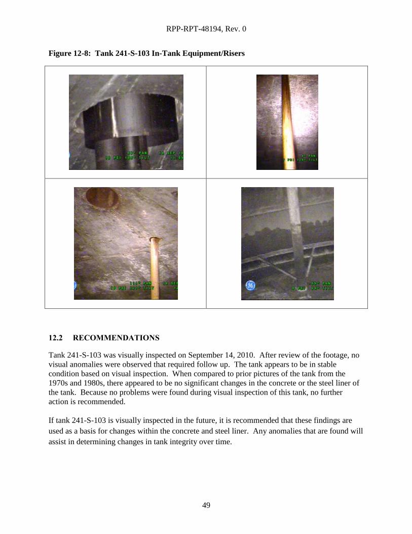
12.1.3 In-Tank Equipment/Risers
All the visible in-tank equipment and risers appeared to be in good condition. Some of these can
be seen in Figure 12-8.
12
111728-04cn
RPP-RPT-48194, Rev. 0
49
Figure 12-8: Tank 241-S-103 In-Tank Equipment/Risers
12.2 RECOMMENDATIONS
Tank 241-S-103 was visually inspected on September 14, 2010. After review of the footage, no
visual anomalies were observed that required follow up. The tank appears to be in stable
condition based on visual inspection. When compared to prior pictures of the tank from the
1970s and 1980s, there appeared to be no significant changes in the concrete or the steel liner of
the tank. Because no problems were found during visual inspection of this tank, no further
action is recommended.
If tank 241-S-103 is visually inspected in the future, it is recommended that these findings are
used as a basis for changes within the concrete and steel liner. Any anomalies that are found will
assist in determining changes in tank integrity over time.
RPP-RPT-48194, Rev. 0
50
13.0 TANK 241-S-104
13.1 RESULTS AND CONCLUSION
Tank 241-S-104 was visually inspected on August 26, 2010. The footage taken by the camera
was carefully reviewed for any visible anomalies on the inside of the tank (above the waste level)
on the surface of the steel liner and concrete dome to identify any areas of concern that would
indicate degradation to the structural integrity of the tank.
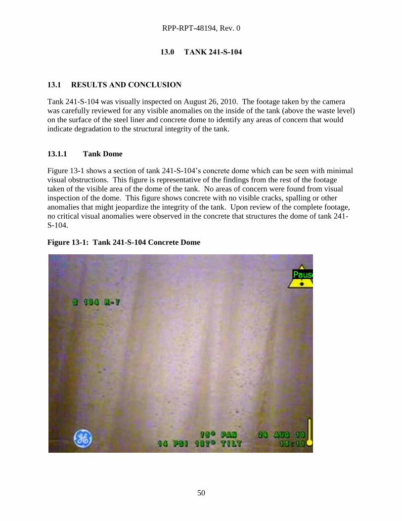
13.1.1 Tank Dome
Figure 13-1 shows a section of tank 241-S-104’s concrete dome which can be seen with minimal
visual obstructions. This figure is representative of the findings from the rest of the footage
taken of the visible area of the dome of the tank. No areas of concern were found from visual
inspection of the dome. This figure shows concrete with no visible cracks, spalling or other
anomalies that might jeopardize the integrity of the tank. Upon review of the complete footage,
no critical visual anomalies were observed in the concrete that structures the dome of tank 241-
S-104.
Figure 13-1: Tank 241-S-104 Concrete Dome
RPP-RPT-48194, Rev. 0
51
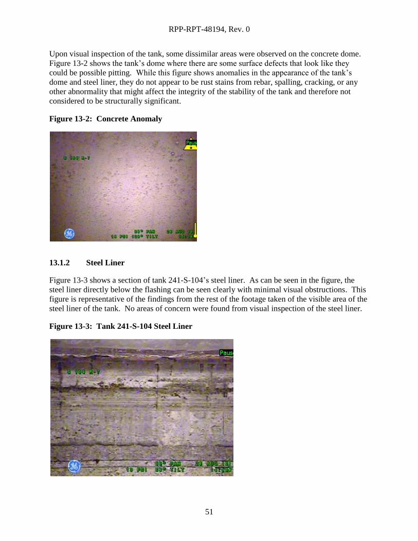
Upon visual inspection of the tank, some dissimilar areas were observed on the concrete dome.
Figure 13-2 shows the tank’s dome where there are some surface defects that look like they
could be possible pitting. While this figure shows anomalies in the appearance of the tank’s
dome and steel liner, they do not appear to be rust stains from rebar, spalling, cracking, or any
other abnormality that might affect the integrity of the stability of the tank and therefore not
considered to be structurally significant.
Figure 13-2: Concrete Anomaly
13.1.2 Steel Liner
Figure 13-3 shows a section of tank 241-S-104’s steel liner. As can be seen in the figure, the
steel liner directly below the flashing can be seen clearly with minimal visual obstructions. This
figure is representative of the findings from the rest of the footage taken of the visible area of the
steel liner of the tank. No areas of concern were found from visual inspection of the steel liner.
Figure 13-3: Tank 241-S-104 Steel Liner
RPP-RPT-48194, Rev. 0
52
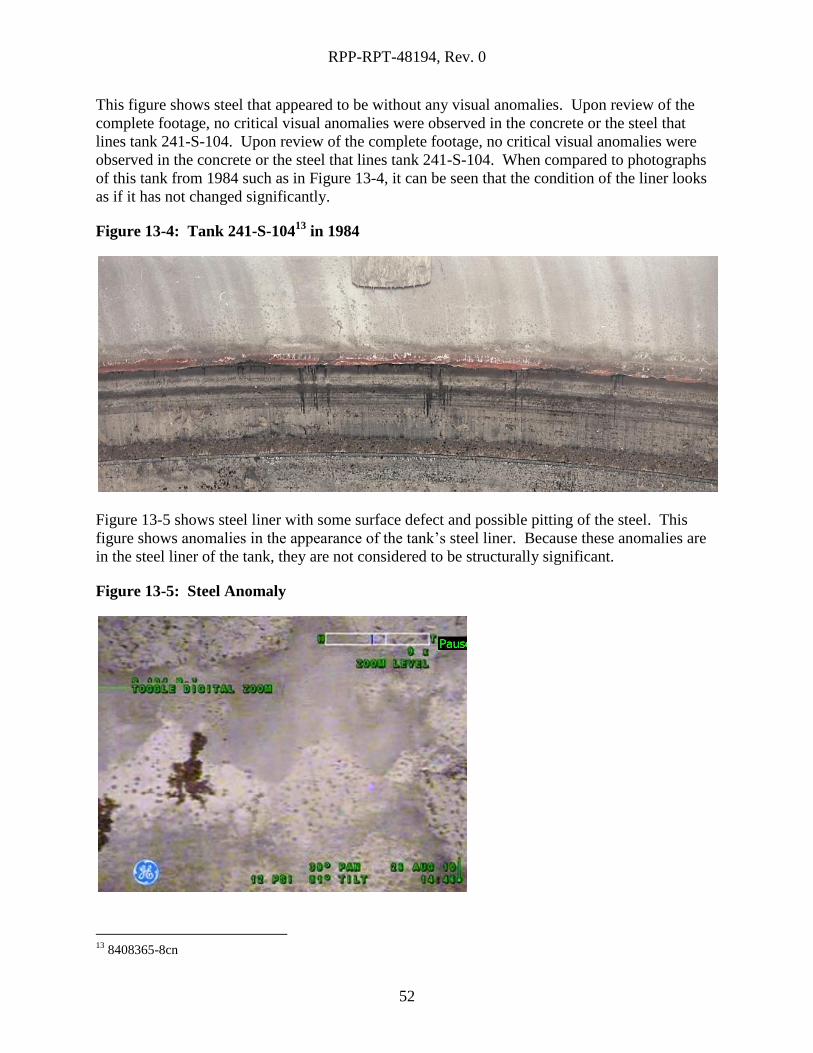
This figure shows steel that appeared to be without any visual anomalies. Upon review of the
complete footage, no critical visual anomalies were observed in the concrete or the steel that
lines tank 241-S-104. Upon review of the complete footage, no critical visual anomalies were
observed in the concrete or the steel that lines tank 241-S-104. When compared to photographs
of this tank from 1984 such as in Figure 13-4, it can be seen that the condition of the liner looks
as if it has not changed significantly.
Figure 13-4: Tank 241-S-10413
in 1984
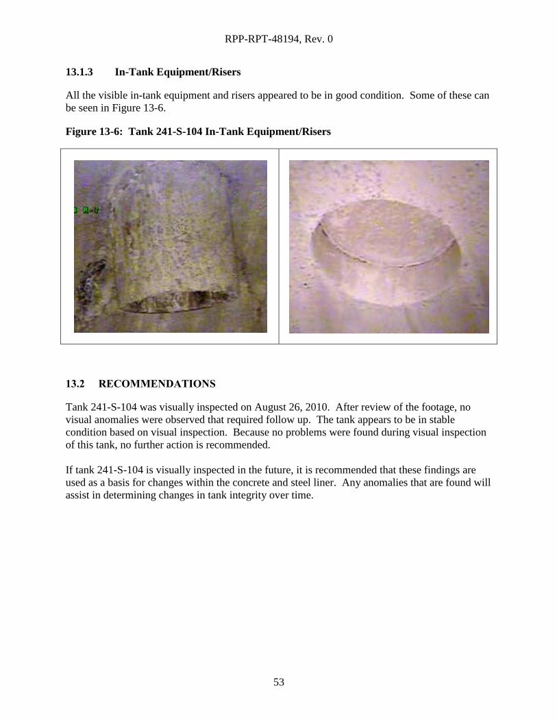
Figure 13-5 shows steel liner with some surface defect and possible pitting of the steel. This
figure shows anomalies in the appearance of the tank’s steel liner. Because these anomalies are
in the steel liner of the tank, they are not considered to be structurally significant.
Figure 13-5: Steel Anomaly
13
8408365-8cn
RPP-RPT-48194, Rev. 0
53
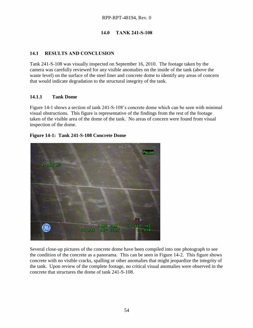
13.1.3 In-Tank Equipment/Risers
All the visible in-tank equipment and risers appeared to be in good condition. Some of these can
be seen in Figure 13-6.
Figure 13-6: Tank 241-S-104 In-Tank Equipment/Risers
13.2 RECOMMENDATIONS
Tank 241-S-104 was visually inspected on August 26, 2010. After review of the footage, no
visual anomalies were observed that required follow up. The tank appears to be in stable
condition based on visual inspection. Because no problems were found during visual inspection
of this tank, no further action is recommended.
If tank 241-S-104 is visually inspected in the future, it is recommended that these findings are
used as a basis for changes within the concrete and steel liner. Any anomalies that are found will
assist in determining changes in tank integrity over time.
RPP-RPT-48194, Rev. 0
54
14.0 TANK 241-S-108
14.1 RESULTS AND CONCLUSION
Tank 241-S-108 was visually inspected on September 16, 2010. The footage taken by the
camera was carefully reviewed for any visible anomalies on the inside of the tank (above the
waste level) on the surface of the steel liner and concrete dome to identify any areas of concern
that would indicate degradation to the structural integrity of the tank.
14.1.1 Tank Dome
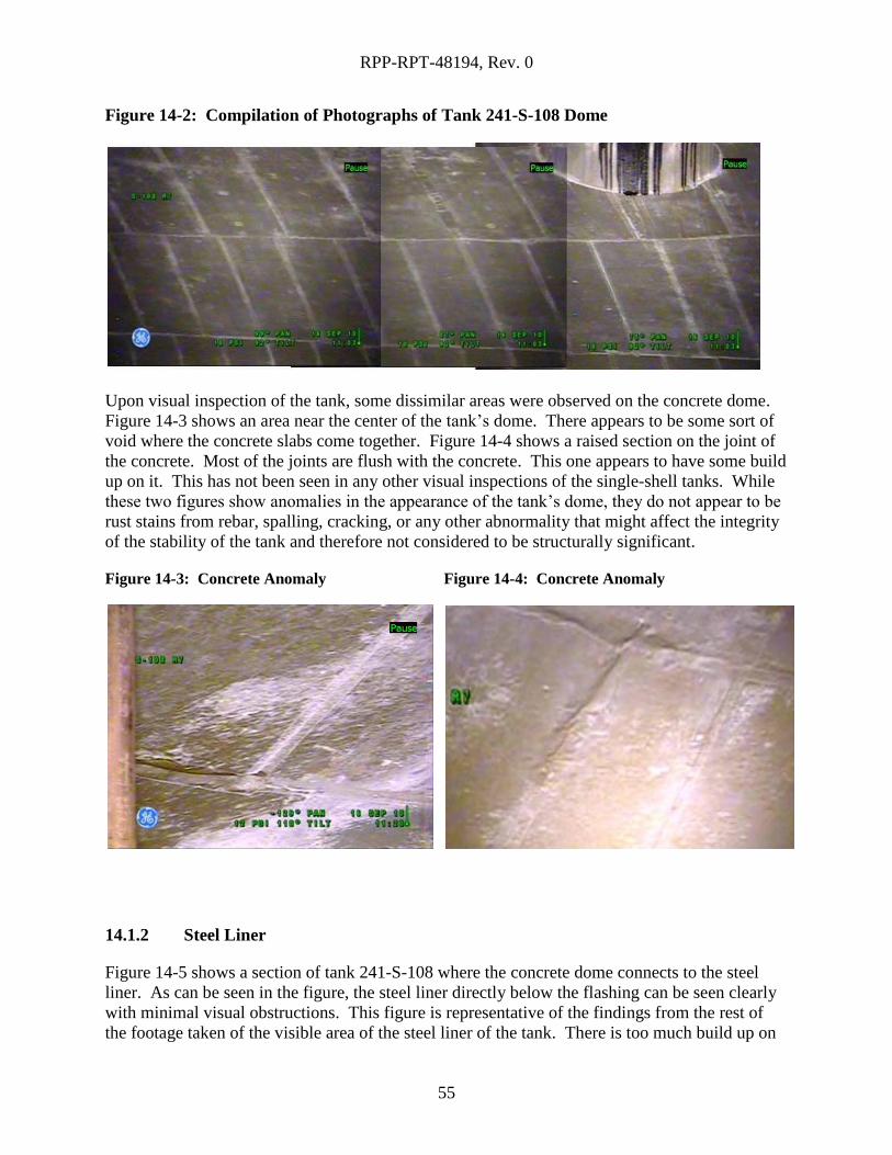
Figure 14-1 shows a section of tank 241-S-108’s concrete dome which can be seen with minimal
visual obstructions. This figure is representative of the findings from the rest of the footage
taken of the visible area of the dome of the tank. No areas of concern were found from visual
inspection of the dome.
Figure 14-1: Tank 241-S-108 Concrete Dome
Several close-up pictures of the concrete dome have been compiled into one photograph to see
the condition of the concrete as a panorama. This can be seen in Figure 14-2. This figure shows
concrete with no visible cracks, spalling or other anomalies that might jeopardize the integrity of
the tank. Upon review of the complete footage, no critical visual anomalies were observed in the
concrete that structures the dome of tank 241-S-108.
RPP-RPT-48194, Rev. 0
55
Figure 14-2: Compilation of Photographs of Tank 241-S-108 Dome
Upon visual inspection of the tank, some dissimilar areas were observed on the concrete dome.
Figure 14-3 shows an area near the center of the tank’s dome. There appears to be some sort of
void where the concrete slabs come together. Figure 14-4 shows a raised section on the joint of
the concrete. Most of the joints are flush with the concrete. This one appears to have some build
up on it. This has not been seen in any other visual inspections of the single-shell tanks. While
these two figures show anomalies in the appearance of the tank’s dome, they do not appear to be
rust stains from rebar, spalling, cracking, or any other abnormality that might affect the integrity
of the stability of the tank and therefore not considered to be structurally significant.
Figure 14-3: Concrete Anomaly
Figure 14-4: Concrete Anomaly
14.1.2 Steel Liner
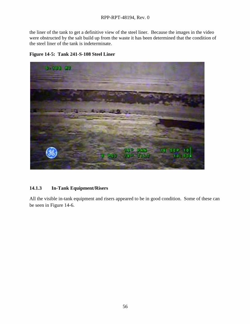
Figure 14-5 shows a section of tank 241-S-108 where the concrete dome connects to the steel
liner. As can be seen in the figure, the steel liner directly below the flashing can be seen clearly
with minimal visual obstructions. This figure is representative of the findings from the rest of
the footage taken of the visible area of the steel liner of the tank. There is too much build up on
RPP-RPT-48194, Rev. 0
56
the liner of the tank to get a definitive view of the steel liner. Because the images in the video
were obstructed by the salt build up from the waste it has been determined that the condition of
the steel liner of the tank is indeterminate.
Figure 14-5: Tank 241-S-108 Steel Liner
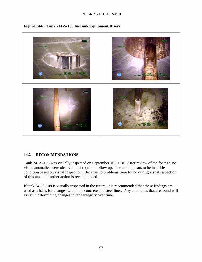
14.1.3 In-Tank Equipment/Risers
All the visible in-tank equipment and risers appeared to be in good condition. Some of these can
be seen in Figure 14-6.
RPP-RPT-48194, Rev. 0
57
Figure 14-6: Tank 241-S-108 In-Tank Equipment/Risers
14.2 RECOMMENDATIONS
Tank 241-S-108 was visually inspected on September 16, 2010. After review of the footage, no
visual anomalies were observed that required follow up. The tank appears to be in stable
condition based on visual inspection. Because no problems were found during visual inspection
of this tank, no further action is recommended.
If tank 241-S-108 is visually inspected in the future, it is recommended that these findings are
used as a basis for changes within the concrete and steel liner. Any anomalies that are found will
assist in determining changes in tank integrity over time.
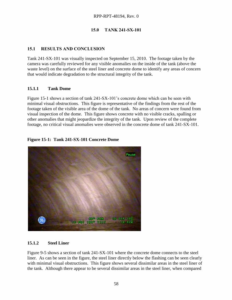
RPP-RPT-48194, Rev. 0
58
15.0 TANK 241-SX-101
15.1 RESULTS AND CONCLUSION
Tank 241-SX-101 was visually inspected on September 15, 2010. The footage taken by the
camera was carefully reviewed for any visible anomalies on the inside of the tank (above the
waste level) on the surface of the steel liner and concrete dome to identify any areas of concern
that would indicate degradation to the structural integrity of the tank.
15.1.1 Tank Dome
Figure 15-1 shows a section of tank 241-SX-101’s concrete dome which can be seen with
minimal visual obstructions. This figure is representative of the findings from the rest of the
footage taken of the visible area of the dome of the tank. No areas of concern were found from
visual inspection of the dome. This figure shows concrete with no visible cracks, spalling or
other anomalies that might jeopardize the integrity of the tank. Upon review of the complete
footage, no critical visual anomalies were observed in the concrete dome of tank 241-SX-101.
Figure 15-1: Tank 241-SX-101 Concrete Dome
15.1.2 Steel Liner
Figure 9-5 shows a section of tank 241-SX-101 where the concrete dome connects to the steel
liner. As can be seen in the figure, the steel liner directly below the flashing can be seen clearly
with minimal visual obstructions. This figure shows several dissimilar areas in the steel liner of
the tank. Although there appear to be several dissimilar areas in the steel liner, when compared
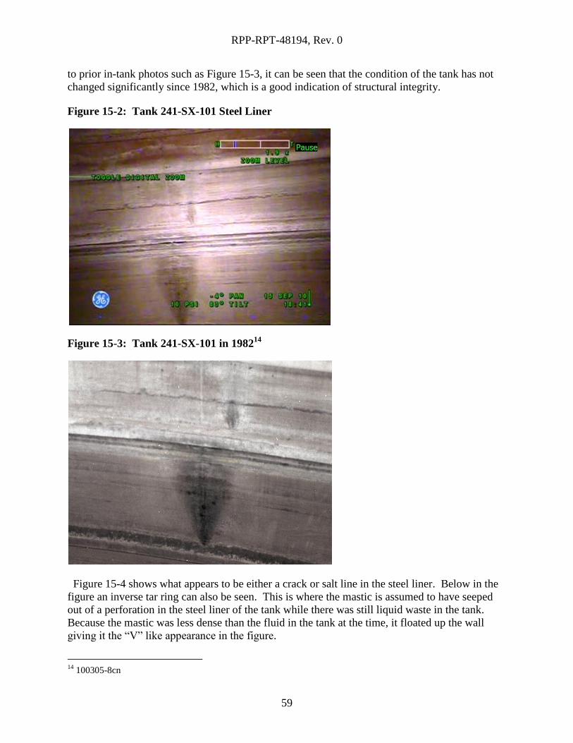
RPP-RPT-48194, Rev. 0
59
to prior in-tank photos such as Figure 15-3, it can be seen that the condition of the tank has not
changed significantly since 1982, which is a good indication of structural integrity.
Figure 15-2: Tank 241-SX-101 Steel Liner
Figure 15-3: Tank 241-SX-101 in 198214
Figure 15-4 shows what appears to be either a crack or salt line in the steel liner. Below in the
figure an inverse tar ring can also be seen. This is where the mastic is assumed to have seeped
out of a perforation in the steel liner of the tank while there was still liquid waste in the tank.
Because the mastic was less dense than the fluid in the tank at the time, it floated up the wall
giving it the “V” like appearance in the figure.
14
100305-8cn
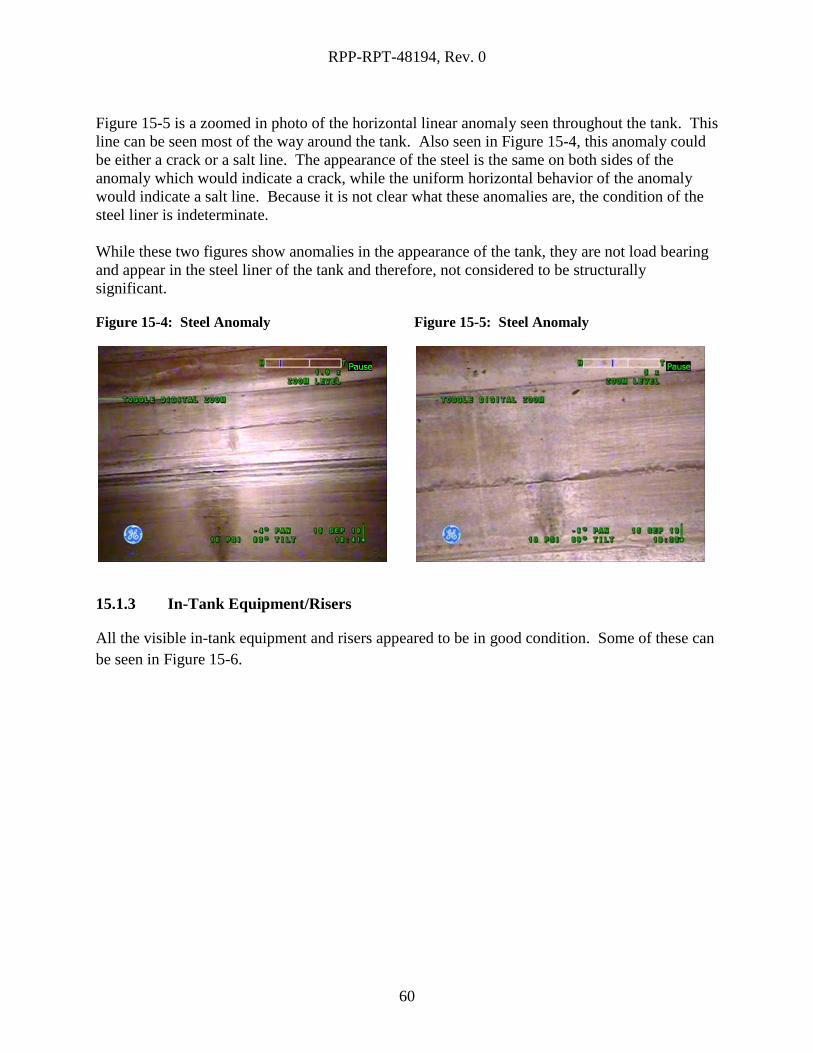
RPP-RPT-48194, Rev. 0
60
Figure 15-5 is a zoomed in photo of the horizontal linear anomaly seen throughout the tank. This
line can be seen most of the way around the tank. Also seen in Figure 15-4, this anomaly could
be either a crack or a salt line. The appearance of the steel is the same on both sides of the
anomaly which would indicate a crack, while the uniform horizontal behavior of the anomaly
would indicate a salt line. Because it is not clear what these anomalies are, the condition of the
steel liner is indeterminate.
While these two figures show anomalies in the appearance of the tank, they are not load bearing
and appear in the steel liner of the tank and therefore, not considered to be structurally
significant.
Figure 15-4: Steel Anomaly
Figure 15-5: Steel Anomaly
15.1.3 In-Tank Equipment/Risers
All the visible in-tank equipment and risers appeared to be in good condition. Some of these can
be seen in Figure 15-6.
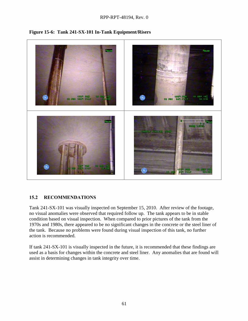
RPP-RPT-48194, Rev. 0
61
Figure 15-6: Tank 241-SX-101 In-Tank Equipment/Risers
15.2 RECOMMENDATIONS
Tank 241-SX-101 was visually inspected on September 15, 2010. After review of the footage,
no visual anomalies were observed that required follow up. The tank appears to be in stable
condition based on visual inspection. When compared to prior pictures of the tank from the
1970s and 1980s, there appeared to be no significant changes in the concrete or the steel liner of
the tank. Because no problems were found during visual inspection of this tank, no further
action is recommended.
If tank 241-SX-101 is visually inspected in the future, it is recommended that these findings are
used as a basis for changes within the concrete and steel liner. Any anomalies that are found will
assist in determining changes in tank integrity over time.
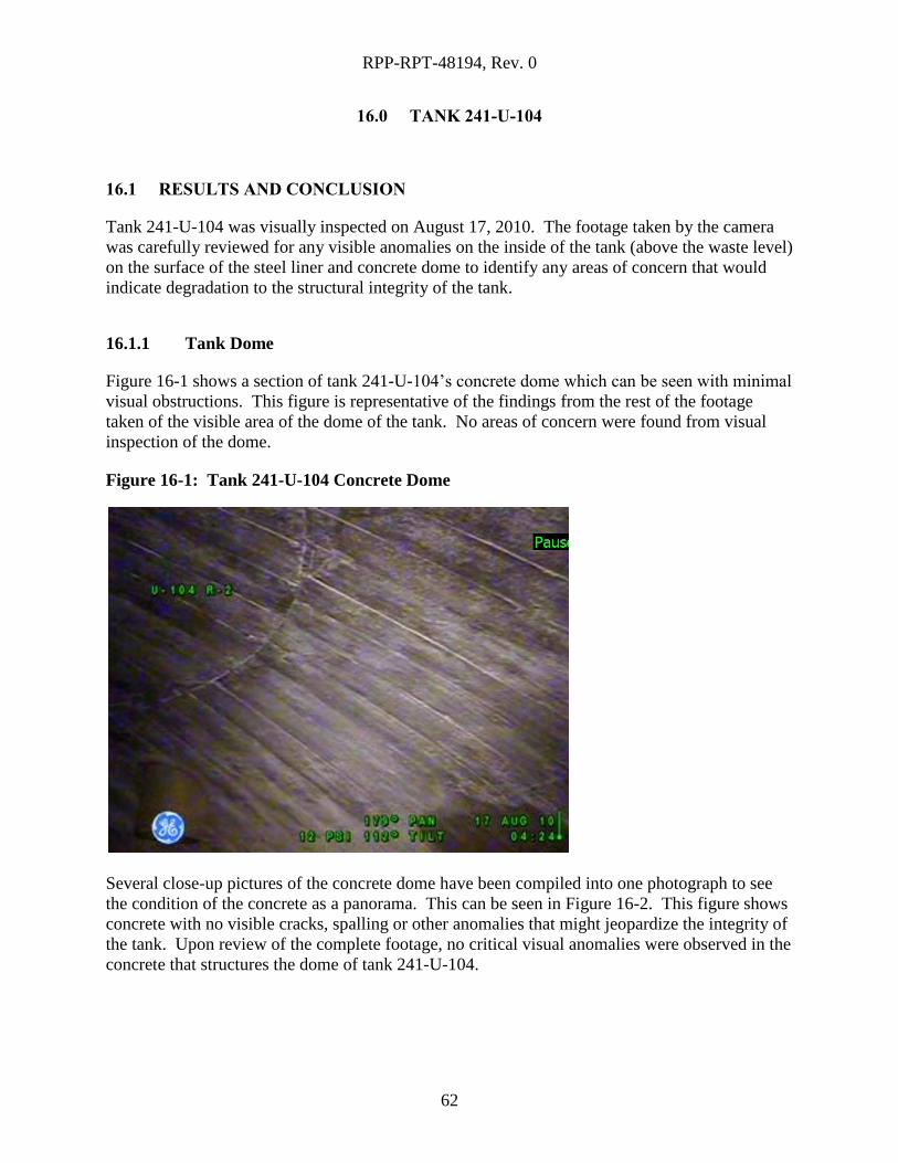
RPP-RPT-48194, Rev. 0
62
16.0 TANK 241-U-104
16.1 RESULTS AND CONCLUSION
Tank 241-U-104 was visually inspected on August 17, 2010. The footage taken by the camera
was carefully reviewed for any visible anomalies on the inside of the tank (above the waste level)
on the surface of the steel liner and concrete dome to identify any areas of concern that would
indicate degradation to the structural integrity of the tank.
16.1.1 Tank Dome
Figure 16-1 shows a section of tank 241-U-104’s concrete dome which can be seen with minimal
visual obstructions. This figure is representative of the findings from the rest of the footage
taken of the visible area of the dome of the tank. No areas of concern were found from visual
inspection of the dome.
Figure 16-1: Tank 241-U-104 Concrete Dome
Several close-up pictures of the concrete dome have been compiled into one photograph to see
the condition of the concrete as a panorama. This can be seen in Figure 16-2. This figure shows
concrete with no visible cracks, spalling or other anomalies that might jeopardize the integrity of
the tank. Upon review of the complete footage, no critical visual anomalies were observed in the
concrete that structures the dome of tank 241-U-104.
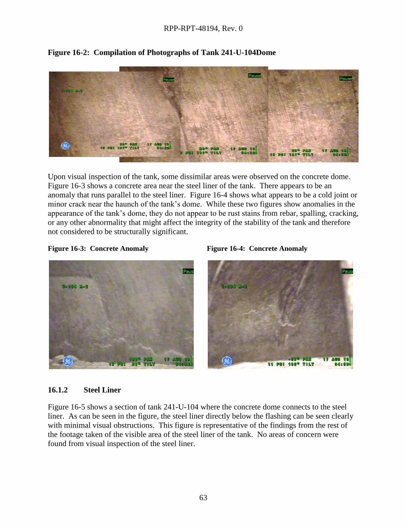
RPP-RPT-48194, Rev. 0
63
Figure 16-2: Compilation of Photographs of Tank 241-U-104Dome
Upon visual inspection of the tank, some dissimilar areas were observed on the concrete dome.
Figure 16-3 shows a concrete area near the steel liner of the tank. There appears to be an
anomaly that runs parallel to the steel liner. Figure 16-4 shows what appears to be a cold joint or
minor crack near the haunch of the tank’s dome. While these two figures show anomalies in the
appearance of the tank’s dome, they do not appear to be rust stains from rebar, spalling, cracking,
or any other abnormality that might affect the integrity of the stability of the tank and therefore
not considered to be structurally significant.
Figure 16-3: Concrete Anomaly
Figure 16-4: Concrete Anomaly
16.1.2 Steel Liner
Figure 16-5 shows a section of tank 241-U-104 where the concrete dome connects to the steel
liner. As can be seen in the figure, the steel liner directly below the flashing can be seen clearly
with minimal visual obstructions. This figure is representative of the findings from the rest of
the footage taken of the visible area of the steel liner of the tank. No areas of concern were
found from visual inspection of the steel liner.
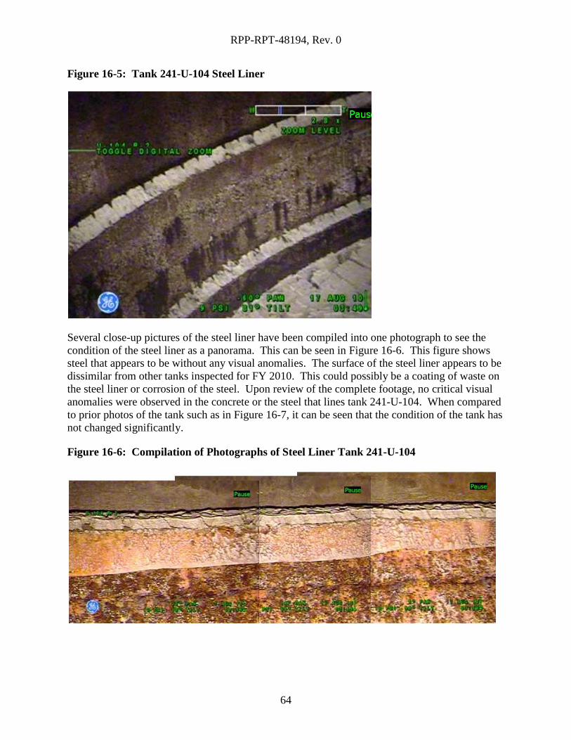
RPP-RPT-48194, Rev. 0
64
Figure 16-5: Tank 241-U-104 Steel Liner
Several close-up pictures of the steel liner have been compiled into one photograph to see the
condition of the steel liner as a panorama. This can be seen in Figure 16-6. This figure shows
steel that appears to be without any visual anomalies. The surface of the steel liner appears to be
dissimilar from other tanks inspected for FY 2010. This could possibly be a coating of waste on
the steel liner or corrosion of the steel. Upon review of the complete footage, no critical visual
anomalies were observed in the concrete or the steel that lines tank 241-U-104. When compared
to prior photos of the tank such as in Figure 16-7, it can be seen that the condition of the tank has
not changed significantly.
Figure 16-6: Compilation of Photographs of Steel Liner Tank 241-U-104
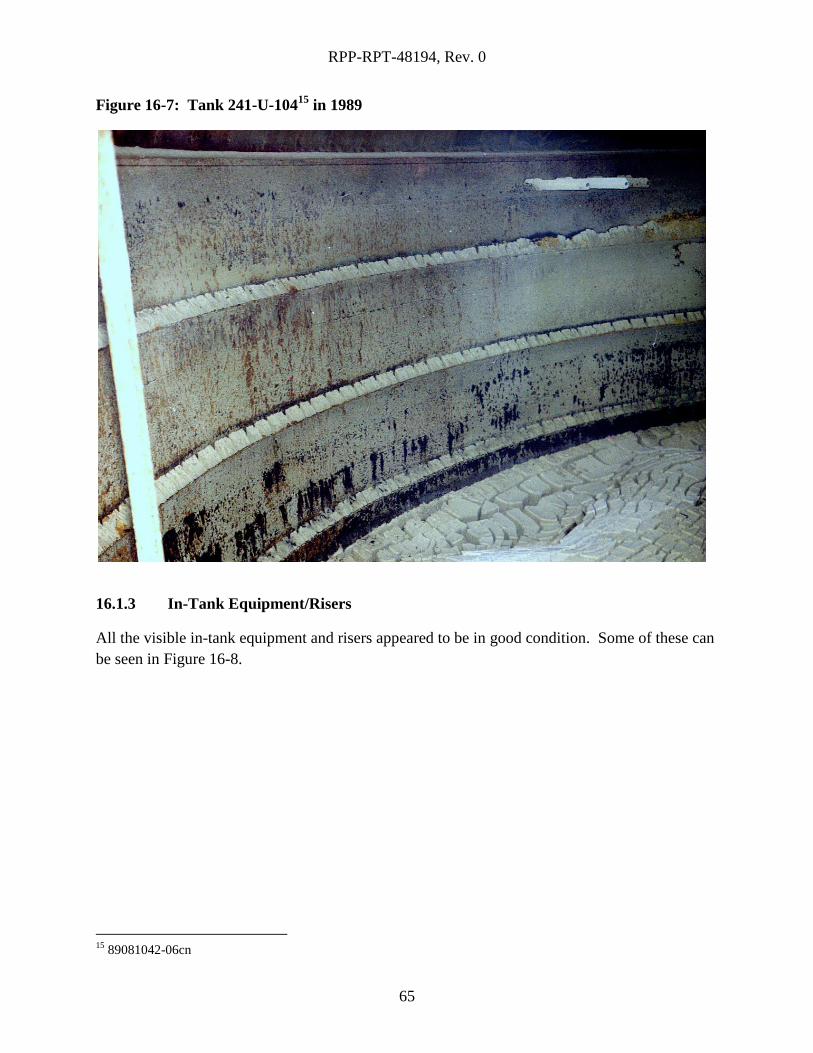
RPP-RPT-48194, Rev. 0
65
Figure 16-7: Tank 241-U-10415
in 1989
16.1.3 In-Tank Equipment/Risers
All the visible in-tank equipment and risers appeared to be in good condition. Some of these can
be seen in Figure 16-8.
15
89081042-06cn
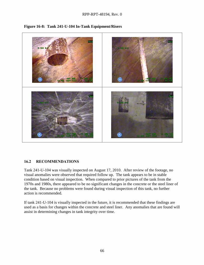
RPP-RPT-48194, Rev. 0
66
Figure 16-8: Tank 241-U-104 In-Tank Equipment/Risers
16.2 RECOMMENDATIONS
Tank 241-U-104 was visually inspected on August 17, 2010. After review of the footage, no
visual anomalies were observed that required follow up. The tank appears to be in stable
condition based on visual inspection. When compared to prior pictures of the tank from the
1970s and 1980s, there appeared to be no significant changes in the concrete or the steel liner of
the tank. Because no problems were found during visual inspection of this tank, no further
action is recommended.
If tank 241-U-104 is visually inspected in the future, it is recommended that these findings are
used as a basis for changes within the concrete and steel liner. Any anomalies that are found will
assist in determining changes in tank integrity over time.
RPP-RPT-48194, Rev. 0
67
17.0 WORKS CITED
ARH-1496. (1969). Review of Storage Tank Integrity . Richland, WA: Atlantic Richfield
Hanford Company.
Engeman, J. (2010). RPP-PLAN-46847 Visual Inspection Plan for Single-Shell Tanks and
Double-Shell Tanks. Richland: Washington River Protection Solutions.
Moore, E., & Metz, W. (1974, July 26). Apparent Liner Crack In SX 112. Richland: Atlantic
Richfield Hanford Company.
Rifaey, S. (2002). Single-Shell Tank System Integrity Assessment Report. Richland, WA: CH2M
Hill Hanford Group, Inc.
Rogers, M. (2010). Waste Tank Summary Report for Month Ending September 30, 2010.
Richland: Washington River Protection Solutions.
Shallman, E. (2010). RPP-PLAN-45082 Implementation Plan for the Single-Shell Tank Integrity
Project. Richland: Washington River Protection Solutions.