Embed Size (px)
Citation preview
MTAG Volume II - Rigid Pavement Preservation 2nd Edition Caltrans Division of Maintenance CHAPTER 4—JOINT RESEALING AND CRACKING SEALING December 11, 2007
Disclaimer
The contents of this guide reflect the views of the authors who are responsible for the facts and accuracy of the data presented herein. The contents do not necessarily reflect the official views or policies of the State of California or the Federal Highway Administration. This guide does not constitute a standard, specification, or regulation.
CHAPTER 4 JOINT RESEALING AND CRACK SEALING
This chapter covers joint resealing and crack sealing for jointed plain concrete pavements (JPCP) and addresses both joint sealing and crack filling. This chapter also discusses appropriate selection and use of joint and crack treatments and materials, design considerations, joint preparation, sealant installation, quality and troubleshooting. The emphasis of this chapter is on sealants rather than fillers.
4.1 PURPOSE AND DESCRIPTION OF TREATMENT
The purpose of joint and crack sealing of JPCP is to reduce infiltration of surface moisture and incompressible materials into joints and cracks. Moisture ingress is one of the primary causes of rigid pavement distress and it can infiltrate the pavement structure in a number of ways. Surface water is generally the primary source of moisture in the pavement structure and thus has the greatest impact on pavement performance. Moisture typically reduces subgrade strength and causes loss of slab support due to subbase and subgrade erosion and pumping, which results in pavement settling – faulting at joints and corner breaks. Incompressible materials lock joints open and create excessive pressure on the joint faces that may cause spalling, blowups, buckling, or in extreme cases, shattering of slabs. Whether or not such distresses occur, continued migration of incompressible materials into joints forces the slabs apart, which may lengthen the pavement and push it against adjacent structures, such as bridge abutments, medians, etc.
Joints in rigid pavements are designed and constructed to permit expansion and contraction of the slabs to prevent cracking of the slabs between joints. Typically they are constructed by sawing the concrete to a certain depth shortly after placement. Joints may be transverse or longitudinal and are often sealed during construction and then resealed as needed throughout the life of the pavement. Caltrans does not seal joints during construction, which are generally straight with vertical cut or formed faces.
Cracks in rigid pavements are generally load associated, or due to excessive thermal movement that is not adequately controlled by the joint system. Cracks may be transverse, longitudinal, or angled, especially at slab corners.
There has been considerable debate and research on the issues and benefits of joint and crack sealing and resealing, including timing (during construction, preservation, and/or maintenance), materials, design and application practices, and the relative effectiveness thereof. Findings have generally indicated that properly selected and applied sealants can reduce water damage and enhance pavement durability. Specific factors that influence sealant performance have been identified, including design, materials selection, joint face preparation, and sealant installation. As a result, design, materials, and application techniques have been improved over the last 30 years, which has resulted in improved durability and performance of joint and crack sealants. Most agencies currently require joint sealing and resealing of highway and airfield JPCP for preservation and/or maintenance.
4-1
MTAG Volume II - Rigid Pavement Preservation 2nd Edition Caltrans Division of Maintenance CHAPTER 4—JOINT RESEALING AND CRACKING SEALING December 11, 2007
The primary differences between sealing and filling are that higher standards are applied for sealing than for filling. Sealants are typically better quality materials than fillers, and the joints and/or cracks to be sealed receive more thorough preparation than those to be merely filled. For these reasons, long term performance of sealed joints and cracks is usually better than performance of filled joints or cracks.
Joints and cracks may open and close horizontally with temperature and moisture changes and may undergo vertical movements as a result of repeated load applications. In order to determine whether to seal or fill a crack, and what type of material to use, it is necessary to establish whether the crack is working (moving) and whether the movement is horizontal or vertical. Working cracks should be routed, cleaned, and sealed with an appropriate sealant; non-working cracks may be filled.
4.2 MATERIALS AND SPECIFICATIONS
There are two primary categories of joint sealant materials for JPCP: liquid and preformed. Liquid materials seal by adhering to the joint or crack faces and are subject to compression and tension. The preformed materials are used for compression seals that operate only in compression and in expansion-type joints.
4.2.1 Sealant Properties The sealant properties needed vary according to the application and location of use. Properties of sealants that have been found critical to long term performance of the sealant material include:
• Durability: The ability of the sealant to withstand the abrasion and damage of traffic and site weather conditions, which include exposure to moisture, ultraviolet light and ozone, along with temperature extremes and rates of temperature changes.
• Extensibility/Modulus: Extensibility is the ability of the sealant to deform without rupturing and it is related to the strain component of elastic modulus. Low modulus (soft, low stress-strain ratio) sealants are generally more extensible than higher modulus (stiffer) materials, but are more vulnerable to intrusion by incompressibles. Low modulus materials are desirable for achieving long term performance in cold climate locations, but may be too soft for use where traffic is heavy or the climate is hot.
• Elasticity/Resilience: Elasticity and resilience are measures of the amount of deformation that is recoverable, i.e., the ability of the sealant to return to its original size and shape after it has been stretched or compressed. High values of elasticity and resilience are desirable and typically indicate good resistance to intrusion of incompressibles. However for some thermoplastic sealants, high resilience and resistance to intrusion may limit extensibility, and trade-offs may be necessary to obtain the desired level of extensibility.
• Adhesiveness: Adhesiveness is the ability of the sealant to adhere to joint faces. It is essential to the performance of liquid sealants, but does not apply to performance of compression seals. The condition and cleanliness of the joint or crack faces are critical to achieving adhesion and proper preparation is required for a successful application.
• Cohesiveness: The ability of the sealant material to hold together and resist internal rupture or tearing. Cohesive failures are more likely to occur in sealants that have aged or stiffened. (Not applicable to compression seals.)
Other properties to consider include compatibility of the sealant with materials it may encounter, such as backer rods or other sealants, and fuel resistance.
4-2
MTAG Volume II - Rigid Pavement Preservation 2nd Edition Caltrans Division of Maintenance CHAPTER 4—JOINT RESEALING AND CRACKING SEALING December 11, 2007
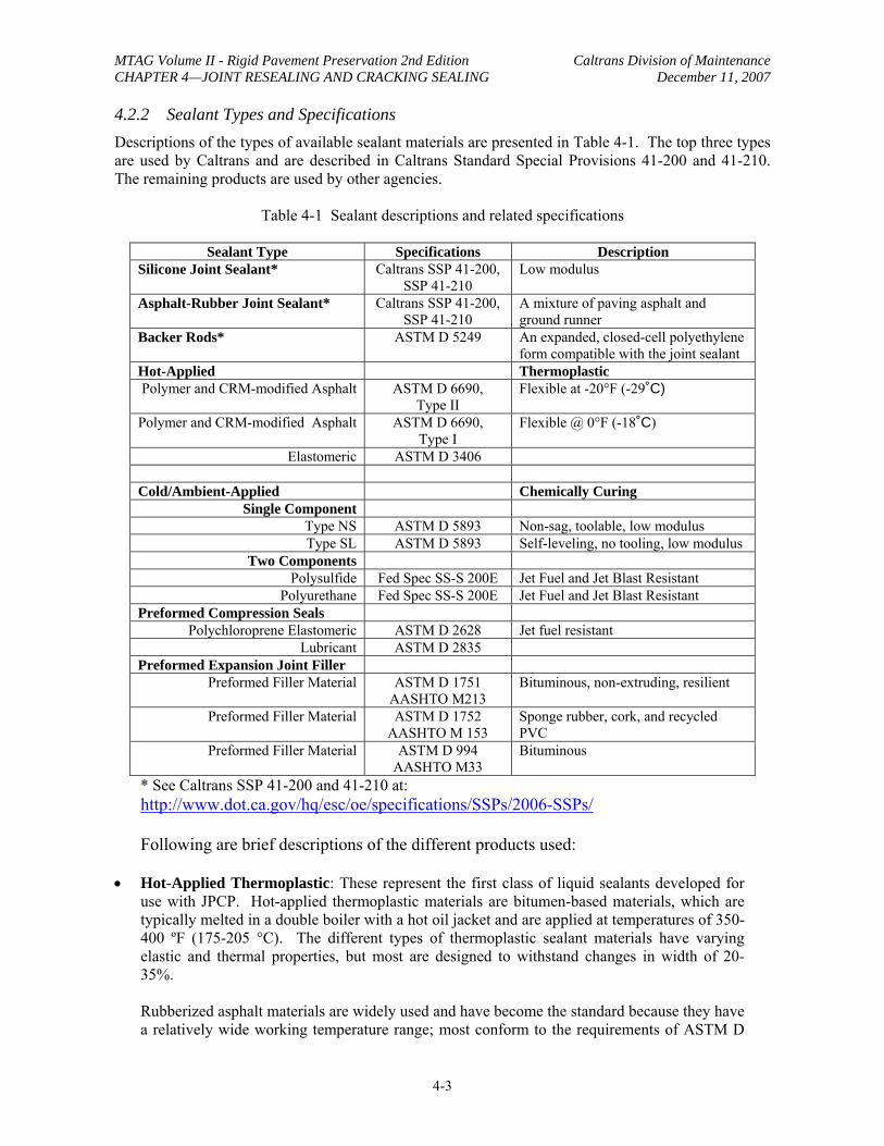
4.2.2 Sealant Types and Specifications Descriptions of the types of available sealant materials are presented in Table 4-1. The top three types are used by Caltrans and are described in Caltrans Standard Special Provisions 41-200 and 41-210. The remaining products are used by other agencies.
Table 4-1 Sealant descriptions and related specifications
Sealant Type Specifications Description Silicone Joint Sealant* Caltrans SSP 41-200,
SSP 41-210 Low modulus
Asphalt-Rubber Joint Sealant* Caltrans SSP 41-200, SSP 41-210
A mixture of paving asphalt and ground runner
Backer Rods* ASTM D 5249 An expanded, closed-cell polyethylene form compatible with the joint sealant
Hot-Applied Thermoplastic Polymer and CRM-modified Asphalt ASTM D 6690,
Type II Flexible at -20°F (-29˚C)
Polymer and CRM-modified Asphalt ASTM D 6690, Type I
Flexible @ 0°F (-18˚C)
Elastomeric ASTM D 3406
Cold/Ambient-Applied Chemically Curing Single Component
Type NS ASTM D 5893 Non-sag, toolable, low modulus Type SL ASTM D 5893 Self-leveling, no tooling, low modulus
Two Components Polysulfide Fed Spec SS-S 200E Jet Fuel and Jet Blast Resistant
Polyurethane Fed Spec SS-S 200E Jet Fuel and Jet Blast Resistant Preformed Compression Seals
Polychloroprene Elastomeric ASTM D 2628 Jet fuel resistant Lubricant ASTM D 2835
Preformed Expansion Joint Filler Preformed Filler Material ASTM D 1751
AASHTO M213 Bituminous, non-extruding, resilient
Preformed Filler Material ASTM D 1752 AASHTO M 153
Sponge rubber, cork, and recycled PVC
Preformed Filler Material ASTM D 994 AASHTO M33
Bituminous
* See Caltrans SSP 41-200 and 41-210 at: http://www.dot.ca.gov/hq/esc/oe/specifications/SSPs/2006-SSPs/
Following are brief descriptions of the different products used:
• Hot-Applied Thermoplastic: These represent the first class of liquid sealants developed for use with JPCP. Hot-applied thermoplastic materials are bitumen-based materials, which are typically melted in a double boiler with a hot oil jacket and are applied at temperatures of 350400 ºF (175-205 °C). The different types of thermoplastic sealant materials have varying elastic and thermal properties, but most are designed to withstand changes in width of 2035%.
Rubberized asphalt materials are widely used and have become the standard because they have a relatively wide working temperature range; most conform to the requirements of ASTM D
4-3
MTAG Volume II - Rigid Pavement Preservation 2nd Edition Caltrans Division of Maintenance CHAPTER 4—JOINT RESEALING AND CRACKING SEALING December 11, 2007
6690. Lower modulus rubberized sealants may be engineered for use in colder climates. Asphalt-rubber sealants can deform without tearing under cold conditions when joint and crack openings are widest, and they are resistant to softening and tracking at high ambient and pavement temperatures. They cost less than silicone sealants, and Caltrans experience indicates a typical service life of approximately 3 to 5 years.
• Cold/Ambient-Applied Thermosetting sealant materials (single and two-component): This family of liquid sealants includes silicones, polysulfides, polyurethanes, and epoxies which generally cure chemically, although some types set by release of solvents. Silicone sealants have been widely used since the 1970′s. Thermosetting sealants are single component silicone polymers that are prepackaged and are ready for immediate use with no heating or mixing required. They are suitable for use in a wide range of ambient and pavement operating temperatures, and typically cure relatively quickly. These sealants have good bond strength and flexibility which allow them to be placed thinner than the thermoplastic sealants. Low modulus silicones can readily withstand 100% extension and 50% compression. However 25% to 50% strain is the typically recommended operating range for higher modulus silicones. Two types of silicone sealants are used: self-leveling, which is applied in a single step with no tooling required; and non-self-leveling, which requires a separate tooling operation to stick the sealant to the joint walls and to form a uniform recessed surface. Two-component polysulfide and polyurethane sealants show variable performance, require mixing and curing, and are rarely used.
Thermosetting sealants are expensive compared to rubberized asphalt and other hot-applied liquid sealants. Costs have been reported to be between 4 and 10 times higher, but thinner application, lower equipment costs for application, and increases in asphalt prices may offset some of these differences in material costs. Caltrans experience indicates that silicone sealants have a service life of approximately 5 to 7 years.
• Preformed Compression Seals: This type of neoprene seal has been used since the early 1960′s, and does not require field heating, mixing, or curing. These seals remain in compression throughout their service life, and perform well over a range of 20-50% in compression. Compression seals are made up of cells that push and hold the sealant against the joint faces; five-celled seals have reportedly provided the most consistent performance in exerting lateral pressure on the joint faces. Caltrans expects compression seals to remain in service for approximately 8-12 years. Failure is typically due to loss of elasticity or loss of compressive recovery (also called compression set), such that the seal no longer pushes against the joint faces. Compression greater than 50% may cause compression set if the cells stick together and interfere with rebound.
• Preformed Expansion Joint Filler: These are compressible filler materials for transverse joints that are designed to accommodate relatively large expansions greater than ½-inch (13 mm). They are placed before the sealant material and act as backer rods. They may be made from bituminous materials, sponge rubber, cork, or recycled PVC, and most are classified as non-extruding. No field heating, mixing or curing is required. It is not necessary to remove
4-4
MTAG Volume II - Rigid Pavement Preservation 2nd Edition Caltrans Division of Maintenance CHAPTER 4—JOINT RESEALING AND CRACKING SEALING December 11, 2007
these fillers when resealing, although bond-breaking tape is usually placed over the old filler before the new sealant is installed.
• Backer Rods: Backer rods are foam materials. Closed cell polyethylene foam is used with cold sealant applications and is moderately compressible. For hot applications, cross-linked polyethylene foam (closed cell, moderately compressible) or polyurethane foam (open-cell, highly compressible) are suitable. Caltrans specifications call for expanded, closed cell polyethylene foam for use with silicone and asphalt-rubber joint sealant. Backer rods are important for installing liquid sealant, to control the quantity, and keep the sealant from flowing out through the bottom. Backer rods also serve as bond breakers to prevent the sealant from sticking to the bottom of the reservoir, which increases stresses within the sealant material that may cause loss of adhesion to the joint faces.
Caltrans Maintenance allows use of a number of commercially available materials for filling joints and cracks. For construction and rehabilitation, Caltrans typically specifies specific types of sealant materials as described in Table 4-1.
4.3 PROJECT SELECTION
Joint and crack sealing, resealing or filling may be performed as part of normal preservation, maintenance, or repair and restoration activities for JPCP, or as preparation for a surface treatment or as structural overlay. To protect the pavement structure from entry of water and the openings from entry of incompressibles, Chapter B of the Caltrans Maintenance Manual identifies individual cracks 1/8 inch (3 mm) or wider as candidates for repair (B.02 (B)) along with areas of “extensive finer cracking”. Joint sealing and resealing are also triggered by a minimum 1/8-inch (3 mm) separation. Projects are selected based on the following criteria:
• The base should be sound and the existing structure adequate, with no slab faulting or settlement.
• Joints and cracks 1/8 inch to 1 inch (3 to 25 mm) wide are candidates to be sealed or filled. Openings less than 1/8 inch (3 mm) wide are not treated individually, and different approaches are used for openings wider than 1 inch (25 mm).
Cracks in CRCP should not be filled with crack sealants.
4.4 DESIGN CONSIDERATIONS
4.4.1 Material Selection The first step in the design process is to select an appropriate sealant for the subject project. Factors to be considered include:
• Project environment, including weather and moisture conditions during installation and over the service life of the sealant. Caltrans recommends sealing transverse joints in freeze-thaw areas to prevent build-up of incompressibles from de-icing treatments. Colder climates require lower modulus sealants than hot climates.
• Type of roadway (Interstate or state highways) and corresponding traffic characteristics including traffic volumes and percentage of heavy trucks – severe conditions will require more durable sealants and/or more frequent replacement.
4-5
MTAG Volume II - Rigid Pavement Preservation 2nd Edition Caltrans Division of Maintenance CHAPTER 4—JOINT RESEALING AND CRACKING SEALING December 11, 2007
• Joint type: Transverse or longitudinal weakened plane or contact joint. Transverse joints require more elastic sealants than do longitudinal joints. Caltrans does not seal contraction joints during construction.
• Joint spacing: Caltrans currently uses relatively short random patterned transverse joint spacing which limits PCC thermal movement and moisture warping. This also reduces the potential for mid-slab cracking. Transverse joint spacing is staggered at intervals of 12, 15, 13, and 14 feet (3.7, 4.6, 4, and 4.3 m) (Caltrans Pavement Tech Notes October 2004 “Concrete Pavement Design Overview”). Use of short JPCP slabs limits the stresses on and in the joint sealant.
• Expected performance and cost effectiveness. • Availability of materials.
If suitable for intended use and site conditions, Caltrans recommends using a sealant that will last the longest. Caltrans has Standard Special Provisions (SSPs) for three types of sealants (Table 4-1) from which the engineer may choose. Two are liquids—asphalt-rubber and silicone—which are typically used with backer rods in or next to existing pavement. The other type is preformed compression seals that are used for new joints where the saw cut faces are smooth and parallel, such as replacement of adjacent slabs. Caltrans does not use compression seals for resealing JPCP because variable conditions of in-place joint faces have caused problems in the past.
Use of preformed expansion joint fillers is now limited to locations in and at the ends of bridge deck pavements or adjacent to other structures. Use of dowel bars has effectively eliminated the need for expansion joints in Caltrans jointed plain concrete pavements (JPCP).
Contraction (weakened plane) joints typically experience the largest horizontal and vertical movements, and corresponding stresses. Vertical movements are caused by load stresses, changes in temperature (slab curling) and moisture (warping). Horizontal movements are primarily due to changes in pavement temperature and moisture content, subject to frictional restraint at the slabsubbase interface.
4.4.2 Joint Resealing Joint resealing in JPCP consists of removing and replacing an existing joint sealant. Joint resealing should be performed when the existing sealant material exhibits distress that indicates it cannot fulfill its intended function, and before the adjacent JPCP is severely damaged. It is often performed along with other pavement restoration activities including spall repair, slab repairs, grinding, etc. Missing or extruded sealant, loss of bond between the sealant and joint face (adhesion loss), tears within the sealant (cohesion loss), hardening/loss of flexibility, weed growth, embedded incompressibles and/or related spalling along the joint are signs of distress that should be considered when selecting the appropriate sealant for joint resealing. Performance may indicate whether a different type of sealant should be substituted. Caltrans uses asphalt-rubber or silicone sealants for joint resealing, each of which provides a range of properties and service lives for a variety of conditions.
The optimum time of the year to perform joint resealing is in the spring or the fall, when installation temperatures are moderate and cracks are likely to be near the middle of their expected range for expansion and contraction. This reduces the potential for the crack sealant or filler to be extended or compressed too much when temperatures increase or decrease after installation.
4-6
MTAG Volume II - Rigid Pavement Preservation 2nd Edition Caltrans Division of Maintenance CHAPTER 4—JOINT RESEALING AND CRACKING SEALING December 11, 2007
4.4.3 Filling Tied longitudinal joints that exhibit little movement may be candidates for filling rather than sealing.
4.4.4 Special Considerations Non-uniform Joint Cracking: For new pavements, it is not unusual for only about one in seven to one in four (14 to 25%) of the joints to crack initially. This is because initial shrinkage cracking of JPCP typically occurs at intervals of about 40 to 150 feet (12 to 45 m), depending on concrete properties, thickness, underlying frictional restraints, and weather conditions at and after placement. Joints between the initial crack locations may take weeks or even months to crack, although the spacings between the random patterned saw cuts are relatively uniform at 12 to 15 feet (3.7 to 4.6 m). Therefore, shrinkage and thermal movements are concentrated at the initially cracked joints rather than uniformly distributed. The resulting initial joint openings are often much wider than the intermediate cracks and remain so over the life of the pavement. This can be seen by substituting the longer lengths between cracked joints in Equation 4-1 for the lengths between saw cuts, which will increase the maximum joint opening, ∆L.
Expansion/Isolation Joints: When resealing expansion/isolation joints, only the sealant material above the preformed expansion joint filler is removed. The filler is left in place and a bond-breaking tape is placed over it to separate the new sealant from any old sealant that may have been absorbed by the filler. For ease of installation, the width of the tape should be at most 1/8-inch (3 mm) narrower than the width of the joint.
Resealing Contraction (Weakened Plane) Joints Located Near Expansion/Isolation Joints: Contraction joints located within about 100 feet (30.5 m) of existing expansion/isolation joints present some special problems. When the expansion joint closes, it allows neighboring contraction joints to open wider than similar joints located farther away. These wider contraction joints may require more extensible sealant, and it may be necessary to use wider backer rods or wider preformed compression seals to insure an adequate seal.
Existing Lane/Shoulder Joints: Studies (including Barksdale and Hicks, 1979) indicate that up to 80% of the surface water that enters a pavement gets in through the lane/shoulder joint. Therefore, proper sealing of this joint is critical to long term pavement performance. When both the traffic lane and the shoulder are concrete, the joint between them is no different than a centerline or tied longitudinal joint and sealing presents no special issues.
However joints between rigid pavement lanes and bituminous shoulders can present major problems for sealant performance. The differences between concrete and hot mix asphalt thermal and structural properties tend to cause differential vertical movement, which may manifest as settlement or heaving of the shoulder. Vertical movement may be larger than horizontal movement. Reservoir widths should be increased to one inch (25 mm) or greater, and depths should be equal to the width. Highly extensible liquid sealants that can adhere well to both concrete and hot mix asphalt are recommended for this application, including asphalt-rubber and specially formulated silicone sealants. Cracks and other defects on the flexible shoulder should be repaired before placing sealant.
Caltrans Maintenance Manual Section B.09 indicates that joints between rigid pavement and flexible shoulders should be filled with a mixture of emulsion and rejuvenator and “topped off with sand.” Adequate drainage should be provided to avoid moisture damage to the emulsion mixture.
4-7
MTAG Volume II - Rigid Pavement Preservation 2nd Edition Caltrans Division of Maintenance CHAPTER 4—JOINT RESEALING AND CRACKING SEALING December 11, 2007
4.4.5 Reservoir Design for Joint Resealing Liquid Sealants
Reservoir design for joint resealing includes selection of sealant reservoir dimensions and sealant configuration. The size of the reservoir is critical to sealant performance, and it is important to consider future needs for resealing and limit the width accordingly if possible. Caltrans Standard Plan P20, Concrete Pavement—Joint Details presents reservoir dimensions and tolerances for liquid sealants with backer rod and for compression seals for new transverse and longitudinal weakened plane joints and for retrofit transverse and longitudinal joints.
However joints in existing pavements are subject to movement, wear, and damage due to traffic and weather. Preparing the joints for resealing often includes saw cutting and reshaping the reservoir to accommodate the selected type of sealant.
The standard method of estimating average maximum horizontal transverse joint opening due to change of PCC temperature for reservoir design purposes is presented below in Equation 4-1 (Darter, 1977) and applies to doweled and non-doweled joints. However this approach does not consider or the calculate vertical movement.
∆L = C L (α∆T + ε) (Eq. 4-1)
where: ∆L = Maximum joint opening, in (mm). α = Thermal coefficient of contraction for PCC, typically 5 to 6 x 10⁻⁶ in/in/ºF (9 to 11 x 10-6
mm/mm/ºC). ε = Drying shrinkage coefficient of the PCC, typically 0.00005 to 0.00025 in/in (mm/mm).
For resealing projects, ε = 0. L = Joint spacing, in (mm). ∆T = Temperature drop, ºF (ºC) = temperature at placement minus the lowest mean minimum
monthly temperature. C = Subbase/slab friction resistance adjustment factor (0.65 for stabilized subbase, 0.80 for
granular subbase, 1.0 for subgrade soil).
Joint spacing is an important factor in Eq. 4-1; the wider the spacing, the greater the length change. The resulting ∆L does not apply to every joint, as opening width varies with variations in material properties, restraint conditions, and initial cracking order. Some studies (Morian, Suthahar and Stoffels, 1999) indicate that Equation 4-1 may underestimate the opening width of transverse joints; this may be a function of the amount of initial joint cracking, treatment (sealing or filling) thereof, and site-specific environmental factors.
Equation 4-1 does not apply to tied construction joints and longitudinal joints, including PCC shoulder joints, because the tiebars restrict joint movement. Tied joints generally move very little and openings are relatively narrow, so sealant for longitudinal joints may not require as much extensibility as for transverse joints. However, tied centerline and shoulder joints of roadway pavements do require sealing because they are usually aligned perpendicular to the pavement drainage slope and are exposed to surface water flow.
Determination of the appropriate minimum saw cut width for the joint reservoir is based on the percent elongation that the sealer must accommodate. The joint width, W, should be sufficient to limit cold weather elongation within the typical design range of 20%; other values may apply for different
4-8
BackerRod
MTAG Volume II - Rigid Pavement Preservation 2nd Edition Caltrans Division of Maintenance CHAPTER 4—JOINT RESEALING AND CRACKING SEALING December 11, 2007
materials. Equation 4-2 is derived from an equation developed by Evans, Smith, and Romine in 1999 based on limiting sealant elongation.
100(M )Winit = max
max%E (Eq. 4-2)
where: Winit = Joint width at the time of sealant placement Mmax = Equivalent to ∆L computed in equation 4-1, the maximum joint opening movement
caused by change of PCC temperature %Emax = Estimated elongation, percent.
A more conservative approach is to assume that a joint between two slabs may be called upon to take the total movement of both slabs, in which case the maximum joint opening, Mmax, is assumed to be 2(∆L) (Evans, Smith, and Romine, 1999).
Shape Factor for Liquid Sealant Reservoirs
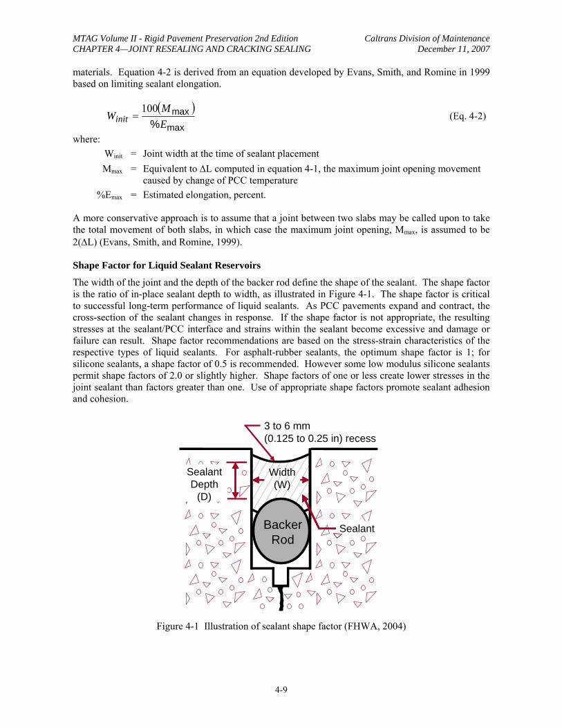
The width of the joint and the depth of the backer rod define the shape of the sealant. The shape factor is the ratio of in-place sealant depth to width, as illustrated in Figure 4-1. The shape factor is critical to successful long-term performance of liquid sealants. As PCC pavements expand and contract, the cross-section of the sealant changes in response. If the shape factor is not appropriate, the resulting stresses at the sealant/PCC interface and strains within the sealant become excessive and damage or failure can result. Shape factor recommendations are based on the stress-strain characteristics of the respective types of liquid sealants. For asphalt-rubber sealants, the optimum shape factor is 1; for silicone sealants, a shape factor of 0.5 is recommended. However some low modulus silicone sealants permit shape factors of 2.0 or slightly higher. Shape factors of one or less create lower stresses in the joint sealant than factors greater than one. Use of appropriate shape factors promote sealant adhesion and cohesion.
3 to 6 mm (0.125 to 0.25 in) recess
Sealant Depth
(D)
Width (W)
SealantBacker Rod
Figure 4-1 Illustration of sealant shape factor (FHWA, 2004)
4-9
MTAG Volume II - Rigid Pavement Preservation 2nd Edition Caltrans Division of Maintenance CHAPTER 4—JOINT RESEALING AND CRACKING SEALING December 11, 2007
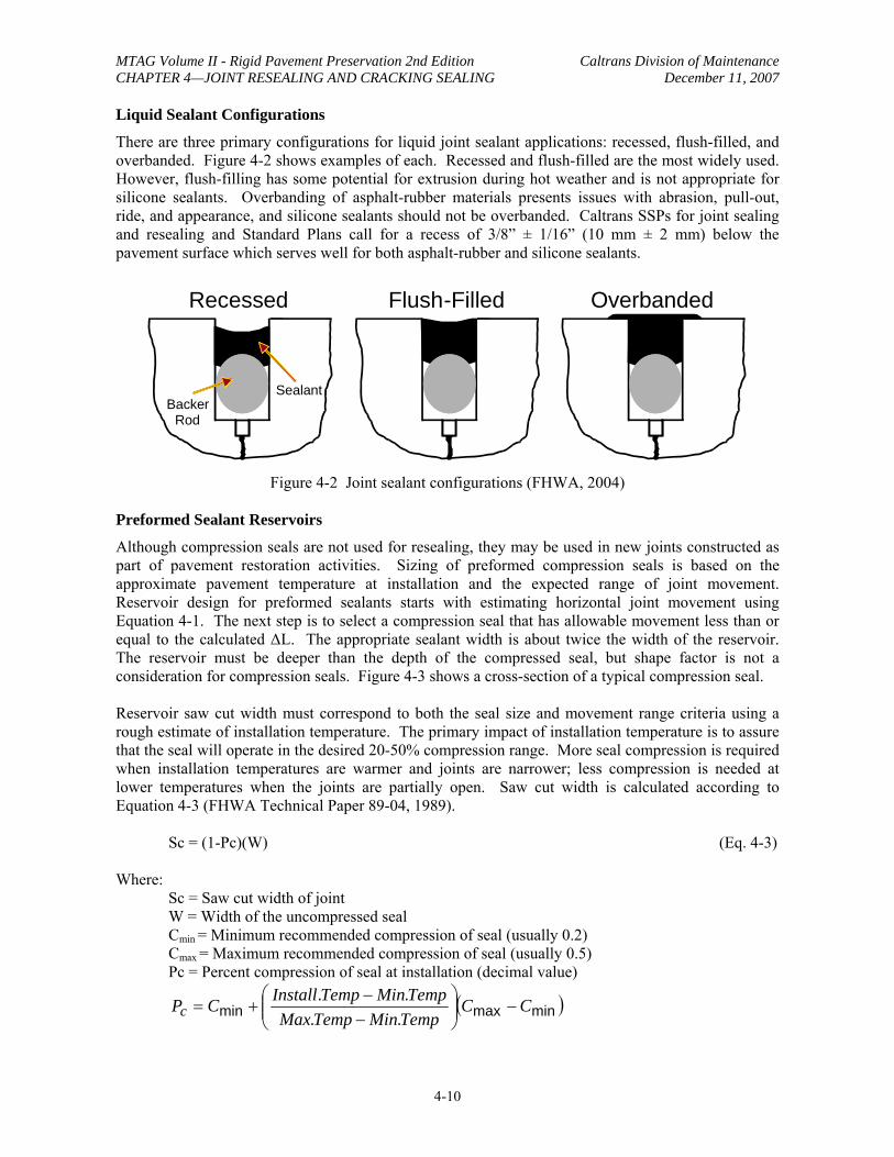
Liquid Sealant Configurations
There are three primary configurations for liquid joint sealant applications: recessed, flush-filled, and overbanded. Figure 4-2 shows examples of each. Recessed and flush-filled are the most widely used. However, flush-filling has some potential for extrusion during hot weather and is not appropriate for silicone sealants. Overbanding of asphalt-rubber materials presents issues with abrasion, pull-out, ride, and appearance, and silicone sealants should not be overbanded. Caltrans SSPs for joint sealing and resealing and Standard Plans call for a recess of 3/8” ± 1/16” (10 mm ± 2 mm) below the pavement surface which serves well for both asphalt-rubber and silicone sealants.
Recessed Flush-Filled Overbanded
Sealant Backer
Rod
Figure 4-2 Joint sealant configurations (FHWA, 2004)
Preformed Sealant Reservoirs
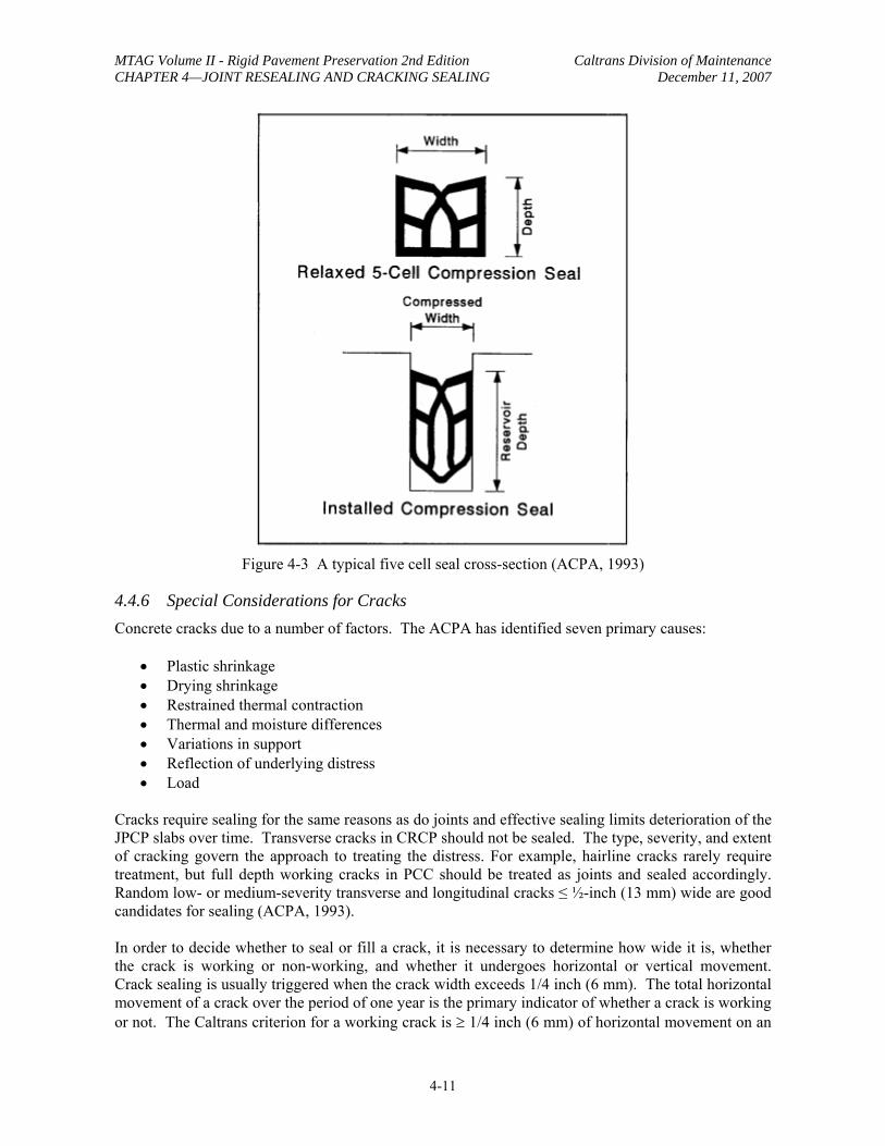
Although compression seals are not used for resealing, they may be used in new joints constructed as part of pavement restoration activities. Sizing of preformed compression seals is based on the approximate pavement temperature at installation and the expected range of joint movement. Reservoir design for preformed sealants starts with estimating horizontal joint movement using Equation 4-1. The next step is to select a compression seal that has allowable movement less than or equal to the calculated ∆L. The appropriate sealant width is about twice the width of the reservoir. The reservoir must be deeper than the depth of the compressed seal, but shape factor is not a consideration for compression seals. Figure 4-3 shows a cross-section of a typical compression seal.
Reservoir saw cut width must correspond to both the seal size and movement range criteria using a rough estimate of installation temperature. The primary impact of installation temperature is to assure that the seal will operate in the desired 20-50% compression range. More seal compression is required when installation temperatures are warmer and joints are narrower; less compression is needed at lower temperatures when the joints are partially open. Saw cut width is calculated according to Equation 4-3 (FHWA Technical Paper 89-04, 1989).
Sc = (1-Pc)(W) (Eq. 4-3)
Where: Sc = Saw cut width of joint W = Width of the uncompressed seal Cmin = Minimum recommended compression of seal (usually 0.2) Cmax = Maximum recommended compression of seal (usually 0.5) Pc = Percent compression of seal at installation (decimal value)
⎛ Install.Temp − Min.Temp ⎞Pc = Cmin + ⎟⎟⎜⎜ (Cmax − Cmin )⎝ Max.Temp − Min.Temp ⎠
4-10
MTAG Volume II - Rigid Pavement Preservation 2nd Edition Caltrans Division of Maintenance CHAPTER 4—JOINT RESEALING AND CRACKING SEALING December 11, 2007
Figure 4-3 A typical five cell seal cross-section (ACPA, 1993)
4.4.6 Special Considerations for Cracks Concrete cracks due to a number of factors. The ACPA has identified seven primary causes:
• Plastic shrinkage • Drying shrinkage • Restrained thermal contraction • Thermal and moisture differences • Variations in support • Reflection of underlying distress • Load
Cracks require sealing for the same reasons as do joints and effective sealing limits deterioration of the JPCP slabs over time. Transverse cracks in CRCP should not be sealed. The type, severity, and extent of cracking govern the approach to treating the distress. For example, hairline cracks rarely require treatment, but full depth working cracks in PCC should be treated as joints and sealed accordingly. Random low- or medium-severity transverse and longitudinal cracks ≤ ½-inch (13 mm) wide are good candidates for sealing (ACPA, 1993).
In order to decide whether to seal or fill a crack, it is necessary to determine how wide it is, whether the crack is working or non-working, and whether it undergoes horizontal or vertical movement. Crack sealing is usually triggered when the crack width exceeds 1/4 inch (6 mm). The total horizontal movement of a crack over the period of one year is the primary indicator of whether a crack is working or not. The Caltrans criterion for a working crack is ≥ 1/4 inch (6 mm) of horizontal movement on an
4-11
MTAG Volume II - Rigid Pavement Preservation 2nd Edition Caltrans Division of Maintenance CHAPTER 4—JOINT RESEALING AND CRACKING SEALING December 11, 2007
annual basis. Vertical movement is not usually calculated although it may affect sealant performance. Working cracks can be transverse or longitudinal to the pavement, but are most often transverse. Working cracks with limited spalling or edge deterioration should be routed and sealed rather than filled. Crack sealing requires thorough crack preparation and typically uses specialized or high quality materials; it should perform longer than simple crack filling.
When cracks are not working, or when cracks are closely spaced and have little movement, less costly crack filling may be an acceptable alternate to crack sealing. Filling is considered to be a relatively short-term treatment, but may serve well for low traffic volume pavements. Crack filling typically involves less crack preparation than sealing and performance requirements for filler materials may be more modest. Note that not all cracks need to be filled; only those 1/8” (3 mm) or more in width and which are full depth cracks need to be filled. Filling partial-depth cracks like those in CRCP can be detrimental and should not be attempted.
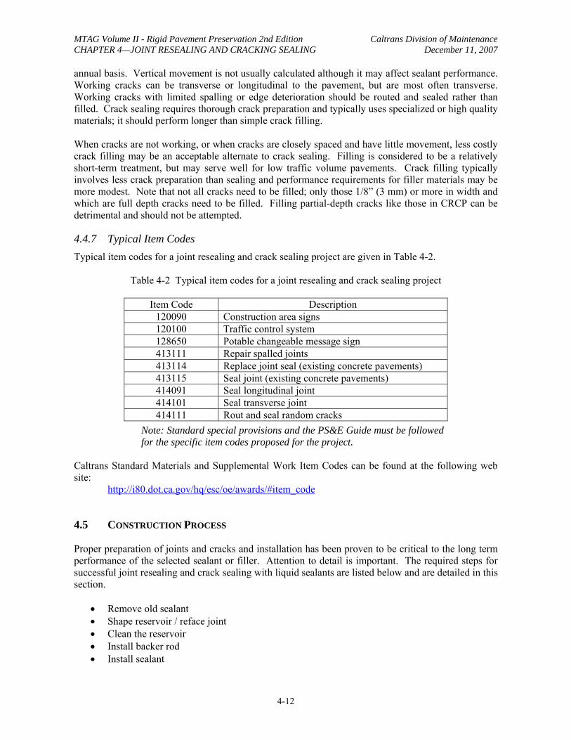
4.4.7 Typical Item Codes Typical item codes for a joint resealing and crack sealing project are given in Table 4-2.
Table 4-2 Typical item codes for a joint resealing and crack sealing project
Item Code Description 120090 Construction area signs 120100 Traffic control system 128650 Potable changeable message sign 413111 Repair spalled joints 413114 Replace joint seal (existing concrete pavements) 413115 Seal joint (existing concrete pavements) 414091 Seal longitudinal joint 414101 Seal transverse joint 414111 Rout and seal random cracks
Note: Standard special provisions and the PS&E Guide must be followed for the specific item codes proposed for the project.
Caltrans Standard Materials and Supplemental Work Item Codes can be found at the following web site:
http://i80.dot.ca.gov/hq/esc/oe/awards/#item_code
4.5 CONSTRUCTION PROCESS
Proper preparation of joints and cracks and installation has been proven to be critical to the long term performance of the selected sealant or filler. Attention to detail is important. The required steps for successful joint resealing and crack sealing with liquid sealants are listed below and are detailed in this section.
• Remove old sealant • Shape reservoir / reface joint • Clean the reservoir • Install backer rod • Install sealant
4-12
MTAG Volume II - Rigid Pavement Preservation 2nd Edition Caltrans Division of Maintenance CHAPTER 4—JOINT RESEALING AND CRACKING SEALING December 11, 2007
4.5.1 Traffic Control and Safety The traffic control plan for joint and crack resealing shall be prepared in accordance with the Caltrans Safety Manual and the Caltrans Code of Safe Operating Practices. The signs and devices used must match the traffic control plan. The work zone must conform to Caltrans practice and requirements set forth in the Caltrans Safety Manual and the Code of Safe Operating Practices along with any other pertinent requirements. Each worker must be fully equipped with the required safety equipment and clothing. Signage shall be removed when it no longer applies.
Depending on the project location, size and amount of work, one of the following types of traffic control alternatives may be considered:
• Complete roadbed closure • Continuous lane closure • Weekend closure • Nighttime closure
4.5.2 Equipment Equipment for preparing and cleaning joints and/or cracks includes: rectangular joint plows, diamond saws, routers, high pressure air and/or water blaster(s), and sandblasters.
A “joint plow” is a blade that is mounted on the hydraulic mount of a tractor or the bucket of a skid loader that can move vertically and horizontally in the joint without binding. The plow blade is inserted into the joint and pulled along each joint edge to scrape the sealant off the joint faces. To avoid damaging the joint faces, the blade must be rectangular and fit freely into the joint. Caltrans does not allow V-shaped plows. Blades of several widths should be on hand, as joint widths are seldom uniform over an entire project.
Diamond-bladed saws are water-cooled devices equipped with diamond-edged blades. A single, full-width blade is useful for maintaining joint width; however, the edges wear quickly, thus reducing the effectiveness of sawing. Two blades separated by a spacer to achieve the desired width can be used on the same arbor, but the blades are thinner and may warp if overheated. Diamond saws may be used on fairly straight cracks. Routers are used to form a reservoir along cracks.
Power-driven wire brushes should not be used to remove old sealant or to clean PCC pavement joints. Air blasting equipment consists of high-pressure air compressors with hoses and spray wands. High-pressure air compressors are effective at removing dry dust and debris from a joint. Caltrans SSPs require a minimum compressed air delivery rate of 120 cubic feet per minute (3.4 m3/min), with a minimum nozzle pressure of 90 psi (0.6 MPa). The air shall be free of oil and moisture.
Sandblasting equipment is used to remove laitance, remaining debris, and remnants of old sealant. It includes a compressed air unit, a sandblasting machine, hoses, and a spray wand with a venturi-type nozzle. Caltrans SSPs do not distinguish between compressed air requirements for air blasting and sandblasting.
Air compressors must be equipped with working water and oil traps to prevent contamination of the joint faces. To ensure oil- or water-free operations, compressors are tested by air blasting into a clean white cloth, which is then checked for contamination.
Equipment for sealer and/or filler installation includes: melters for hot applied materials, and pumps and applicators for hot- and cold-applied materials, materials.
4-13
MTAG Volume II - Rigid Pavement Preservation 2nd Edition Caltrans Division of Maintenance CHAPTER 4—JOINT RESEALING AND CRACKING SEALING December 11, 2007
Melters are used to heat and mix hot-applied thermoplastic materials. Melters burn either propane or diesel fuel, and the resulting heat is applied to a transfer oil that surrounds a double-jacketed melting vat containing the sealant material. This apparatus provides a controlled and uniform heat (350-400ºF [175-205°C]) for application. Temperature control is required to avoid overheating and degradation of the sealant. Agitators are required for asphalt-rubber sealants.
Compressed air-powered silicone pumps are used to pump one-component silicone materials from storage containers for application at ambient temperature. A feed rate of at least 0.4 gallons/minute (1.5 L/min) is recommended. The applicator wand is equipped with a nozzle that fits into the reservoir to allow filling from the bottom up.
Applicators for hot-applied sealers are generally pressure-wand systems. Sealant material is pumped directly from the melter tank through the hoses and applicator wand, and into the bottom of the joint.
4.5.3 Remove Old Sealant Removal of the old sealant material is critical to provide a surface to which the new sealant can bond, especially since the liquids used for resealing work by adhesion to the joint faces. It is important to avoid damaging the joint reservoir during the removal process. Sawing with diamond blades is an efficient method for combining sealant removal and joint refacing steps, and has thus become very popular. However, sawing works best for removing somewhat hardened sealants. Sticky, temperature susceptible materials may gum up the saw blades and/or joint faces. Rectangular joint plows may also be used, or a knife blade can be used to cut the sealer away from the PCC. Caltrans SSP 41-210 allows these three removal methods and also requires removal of backer rods. Contractors are required to submit the proposed removal method for Caltrans review and approval prior to removal.
4.5.4 Shape Reservoir / Reface Joint If the old sealant was removed by means other than a diamond bladed saw, it may be necessary to perform a separate joint refacing operation using wet or dry sawing with diamond blades. Caltrans allows either single pass or double pass saw cuts for this purpose at the Contractor’s option.
Care should be exercised when refacing. Excessive widening of joint reservoirs may change the shape factor and affect performance of the sealant. Wide joints may also increase the likelihood of “wheel slap” which generates unwanted tire noise.
4.5.5 Clean Joint Reservoir Cleaning the reservoir is the most important part of joint sealing. Performance of liquid sealants depends on good adhesion of the sealant to the joint faces. Any dust, dirt or old sealant remaining on the joint faces blocks the new sealant from direct contact and bonding with the JPCP. Aside from old sealant, materials that may contaminate the joints include:
• Water-borne debris (laitance) from wet sawing. • Oil or water blown in by the compressed air stream. • Dust and dirt left behind by the cleaning operation. • Material that enters the joint between cleaning and sealing. • Other contaminants that may inhibit bonding, including moisture condensation.
After joint refacing is completed, the joint should immediately be cleaned with high-pressure air or water, and dried. Caltrans does not allow chemical solvents to be used to wash joints. Cleaning
4-14
MTAG Volume II - Rigid Pavement Preservation 2nd Edition Caltrans Division of Maintenance CHAPTER 4—JOINT RESEALING AND CRACKING SEALING December 11, 2007
narrow joints (less than ¼-inch [6 mm] wide) is more difficult than cleaning joints that are at least 3/8inch (10 mm) wide. Sandblasting follows to remove laitance (wet-sawing residue) and any other residue on the joint faces. The resulting surface texture enhances sealant adhesion. A minimum of one pass is required to clean each joint face, and close attention must be paid to the work to ensure consistent, thorough cleaning. Best practice is to angle the air rather than blasting directly into the reservoir. During the sandblasting operation, the operator should use appropriate safety equipment including a proper helmet and a breathing apparatus. Following sandblasting, the entire length of each joint face should be visibly clean with the concrete exposed.
Final air blasting should be performed no more than one hour before backer rod and sealant installation. Joints and surrounding surfaces should be air blasted in one direction, away from prevailing winds and taking care not to contaminate previously cleaned joints. Care must also be taken not to blow debris into traffic in the adjacent lanes. Caltrans requires vacuum removal of the air blasting debris and residue. When compression seals are to be used for sealing restored joints, sandblasting and final air blasting are not required.
4.5.6 Install Backer Rod Backer rod should be installed as soon as possible after the joints are properly prepared and cleaned. Caltrans requires a minimum air temperature of 40ºF (5°C) and JPCP temperature above the dew point for backer rod installation. The backer rod must be a flexible, non-absorptive material that is compatible with the sealant material being installed. Because reservoir widths vary, several different sizes of backer rods should be available. The diameter of the backer rod should be about 25 percent larger than the joint width; if this does not provide a tight seal, a larger diameter rod should be substituted.
It is critical to install the backer rod to the proper depth, with no gaps between backer rod strips. The rod should be stretched as little as possible to reduce the likelihood of shrinkage and development of gaps. Backer rod may be installed using a special steel roller (single or double-wheeled) or other smooth blunt tool that does not puncture or stretch the backer material.
4.5.7 Install Sealant Immediately before any liquid sealant is installed, the cleanliness and dryness of the joint reservoirs must be verified. Installation requirements may differ for each sealant product, so it is important to understand and follow the manufacturer’s recommendations to avoid unnecessary problems. Recommendations may include limits on pavement and ambient installation temperatures, moisture conditions, and/or on curing time before opening the roadway to traffic.
Hot -Applied Sealants
Hot-applied sealant materials should generally be placed when the air temperature is at least 40ºF (5°C) and rising (FHWA, 2002), but Caltrans requires a minimum installation temperature of 50ºF (10°C) for asphalt-rubber sealants. It is important to follow the manufacturers' recommendations for heating and handling, including maximum sealant temperature, placement temperature, and any limitations on heating time. Many of the polymer- and rubber-modified sealants may break down when heated above the recommended safe heating temperature. Prolonged heating can cause some sealant materials to gel in the heating tank while others experience significant changes (usually losses) in their elastic properties.
The sealant material should be uniformly installed by filling the joint reservoir from the bottom up and pulling the nozzle toward the installer to avoid trapping any air bubbles, but not overfilling it.
4-15
MTAG Volume II - Rigid Pavement Preservation 2nd Edition Caltrans Division of Maintenance CHAPTER 4—JOINT RESEALING AND CRACKING SEALING December 11, 2007
Caltrans Standard Plan P 20 shows that the surface of the sealant is to be recessed 3/8” ± 1/16” (10 mm ± 1.5 mm) below the surface of the pavement to allow room for expansion during hot weather without extruding the sealant from the joint. Some manufacturers recommend that the joint be flush filled with sealant. To avoid “tracking” of the sealant, traffic should not be allowed on the newly sealed joints for about 30 minutes to 1 hour after sealant placement. Consult the manufacturer’s instructions for information regarding opening to traffic, consider effects of site weather conditions, and evaluate the in-place curing before allowing traffic on the newly sealed joints.
Cold-Applied Sealants
Minimum installation temperature for silicone sealants is generally 40ºF (5°C). Silicone sealants should be installed in the same manner as hot-applied sealants, from the bottom to the top of the joint and pulling the nozzle toward the installer. Minimum placement thickness is ¼-inch (6 mm), and shape factor can vary from 0.5 to 2.0. Typical curing time is about one hour, but please check the manufacturer’s instructions for specific recommendations about opening to traffic.
Nonself-leveling silicone sealants must be tooled to force the sealant around the backer rod and against the joint sidewalls, and to form a concave sealant surface. Large diameter backer rod and rubber hose have been used for tooling, which should be performed before the sealant starts curing, generally within about 10 minutes after installation.
Self-leveling silicone sealants do not require tooling, but may flow easily around loose backer rod or out at unblocked joint ends prior to curing, so particular care is required during installation of backer rod and sealant. Some agencies have mandated tooling in order to enhance the bond between the pavement and the sealant even if the material does not require it.
NOTE: When installing both silicone and asphalt-rubber sealants on a single pavement section, for example, where silicone sealant is to be used in the transverse joints and asphalt-rubber in the longitudinal joints, the silicone should be installed first to reduce the potential for contamination of the transverse joint during the longitudinal joint sealing operations (FHWA, 1985). This is not an uncommon occurrence; cold-applied sealants should be installed first, regardless of the orientation of the joint.
Longitudinal Joint Resealing
As previously discussed, there are two types of longitudinal joints in PCC that may be resealed: joints between adjacent PCC slabs and joints between the mainline PCC pavement and an AC shoulder. Although the procedures are basically the same as for transverse joint resealing, there are some additional considerations.
Rigid to Rigid Joints: Longitudinal joints between adjacent JPCP slabs are generally tied together with tiebars, which limits slab movement so that conventional joint sealing operations can be conducted. These joints are generally sealed with a hot-applied material, and typically no reservoir is needed or formed. If transverse joints are to be sealed with silicone, seal them first to prevent contamination by hot-applied sealant material.
Rigid to Flexible Shoulder: Because of the differences in material properties, joints between a JPCP mainline pavement and a flexible pavement shoulder often experience large differential vertical movements that may be accompanied by considerable horizontal movement and separation along the longitudinal joint. Sealing is required to minimize water infiltration. The primary difference from typical transverse joint sealing operations is that an extra wide reservoir (minimum one-inch, shape factor of 1.0) is cut in the existing HMA shoulder to allow for the anticipated movements. If the
4-16
MTAG Volume II - Rigid Pavement Preservation 2nd Edition Caltrans Division of Maintenance CHAPTER 4—JOINT RESEALING AND CRACKING SEALING December 11, 2007
reservoir is of uniform depth, a backer rod is generally not needed. Many agencies routinely use hot-applied materials to seal this joint, although some silicone materials have been developed for this application.
Compression Sealing
Compression seals can be installed in both new and restored transverse joints. Face preparation is limited to identifying areas of raveling, spalling, or other defects that might interfere with sealant compression and allow pop-outs or extrusions, and making suitable repairs prior to installing the seals. Installation of compression seals requires application of a lubricant/adhesive to the seal and the joint faces. The seal is mechanically compressed and inserted into the reservoir. Most of the compression seal manufacturers make installation devices. The most common type is a “compress-eject” machine. These machines have some propulsion and insertion depth control, and they are equipped with a guide to keep them on the joint. They eliminate a number of problems that may be caused by hand installation, such as twisting and stretching. Splicing of compression seals is to be avoided if feasible, as this can create discontinuities; for joints less than 25 feet (7.5 m) in length, only one piece of compression seal should be used. If used for longitudinal joints, the compression seal should be cut at the transverse joint crossings.
4.5.8 Crack Sealing Crack sealing in JPCP follows the same basic steps as joint sealing: refacing, cleaning, backer rod installation, and sealant installation (ACPA, 1993). The first step is to reface the crack to the desired width. However, the orientation of most PCC pavement cracks makes it difficult to create a uniform sealant reservoir directly along the crack. Small diameter, diamond-bladed saws have been used successfully (ACPA, 1993) to form reservoirs. The cutting blades for these saws are typically about 7 to 8 inches (180 to 200 mm) in diameter and ¼- to ½-inch (6 to 12 mm) wide. The width of the saw cut usually yields an appropriate shape factor for the expected crack movement. Smaller blade diameters and some lightweight two- or three-wheel unit designs allow crack saws to pivot and follow irregular crack profiles. Although the saws are not generally as maneuverable as routers, they don’t have as much potential for spalling the crack faces either.
After the reservoir is created, the crack should be cleaned as if it were a joint to be resealed. Sandblasting is highly recommended. Then the crack is blown with compressed air and the backer rod (if specified) and sealant material are installed. The same precautions that apply to the installation of sealant materials into joints also apply to crack sealing (ACPA, 1993). Use of epoxy or glue working cracks is not generally recommended, as it often contributes to subsequent adjacent thermal cracking.
After installation, the sealant should be visually examined to assure application is complete, with no gaps or obvious defects. Adhesion to the joint faces should be spot-checked with a simple knife test.
4.5.9 Trafficking Curing requirements for sealants and fillers are material-dependent, but may also be affected by on-site weather conditions. Hot applied materials are thermoplastic; they set when they cool and produce a non-tacky finish. A light application of sand may be applied to the surface of the sealant to prevent pick up or pull out by tires. Hot applied sealants typically should be allowed a three to four month curing time prior before being covered with a maintenance overlay or seal coat.
Silicones used by Caltrans are one-part formulations that cure primarily by cross-linking due to ambient moisture. The manufacturer’s recommendations regarding opening to traffic must be followed. Sanding the fresh sealant reduces safety concerns (slick pavements) and improves the
4-17
MTAG Volume II - Rigid Pavement Preservation 2nd Edition Caltrans Division of Maintenance CHAPTER 4—JOINT RESEALING AND CRACKING SEALING December 11, 2007
surface appearance (aesthetics). Excess sand must be swept away before opening the roadway to traffic. Cold applied sealants require a one year cure time prior to being covered with an overlay or seal.
4.5.10 Quality Performance of joint and crack sealants appears to depend at least as much on the preparation and application processes as on the quality of the materials used. The care and workmanship exercised by contractor personnel are critical to the success of joint resealing and crack sealing projects. This section summarizes key aspects of quality control and assurance. Detailed project checklists and troubleshooting guide for every aspect of materials, equipment, and execution are included in Sections 4.7.1 and 4.7.2, towards the end of this chapter.
Project Review
Prior to the start of work, the condition of the subject pavement should be reviewed to verify that no significant changes have occurred since the project was designed, and that the joint and crack treatments are still appropriate as designed. Methods designated for sealant removal, refacing, and cleaning should be reviewed. For joint resealing projects, joint reservoir design(s) and sealant type should be checked with respect to the expected project climate and traffic conditions. Consideration should also be given to project scheduling to evaluate possible effects of expected weather conditions at the time of installation.
The following project documents and submittals should also be reviewed to identify any potential issues:
• Project specifications and design (as bid and awarded). • Project special provisions. • Traffic control plan submitted by the contractor. • Manufacturer’s instructions for sealant handling and installation. • Material safety data sheets (MSDS).
Materials Review
Materials review consists primarily of ensuring that the proposed sealant materials meet project specifications and that sufficient quantities are available which have not been damaged during shipping and storage, and that they remain within their respective shelf lives. This is covered under Caltrans Standard Plan P20, which requires specific diameters of backer rod; however additional sizes are often required to properly prepare individual joints that are wider than typical, therefore some larger sizes should be readily available at the job site.
Equipment Inspection
The equipment used to prepare the joints and cracks and to install the sealant must be examined prior to the start of construction. Some of the most important items to check are listed below. Extensive, detailed lists of specific items are included in the FHWA checklist (FHWA, 2002).
Melters for hot-applied sealants should be inspected to verify that they are functioning properly. Items to inspect include: the hot-oil heating system including thermostats and controls, agitation in the melter vat, valve operation, the hot sealant pumping system including hoses, and size of wand tips.
4-18
MTAG Volume II - Rigid Pavement Preservation 2nd Edition Caltrans Division of Maintenance CHAPTER 4—JOINT RESEALING AND CRACKING SEALING December 11, 2007
Equipment for cold-applied sealants is less complicated. The primary items to check include pump function, condition of the follower plates, condition of the hoses, and size of applicator tips
Joint cleaning and refacing equipment includes air, water, and sand blasters. These devices use air compressors that must meet minimum requirements for volume and pressure, and they require filters or traps for water and oil. Function of the compressors and traps should be verified. For sandblasters, type of abrasives used must be environmentally acceptable and their feed rates properly controlled. Caltrans SSPs do not require use of water blasters but, if used, these must provide the required volume of water and pressure. Size and function of concrete saws and diamond tipped blades should be verified. If used, size and shape of joint plows must also be verified.
Installation
Joint Preparation: Activities involved in joint preparation include removal of old sealant, shaping the reservoir / refacing the joint walls, and cleaning and drying the joint reservoir. The contractor and assistant resident engineer (RE) should verify that these operations are performed correctly with the proper equipment and level of workmanship. Propane torches should no longer be used to dry joint reservoirs to avoid damaging the PCC or adjacent asphalt concrete shoulders. Each joint should be inspected prior to sealing to verify that the joint faces are clean enough for installation of liquid sealants, and identify any locations that need further cleaning.
Install Backer Rod: The primary items to check include installation at the designated depth below the pavement surface and uniformity thereof, and how well the backer rod fits in the joint (is a larger diameter needed?). The backer rod should be inspected to verify that is not being stretched or damaged in the process.
Hot-Applied Sealant Installation: Temperature control is crucial to avoid damaging sealant materials by overheating and to promote uniform application and bonding with joint faces. Inspectors are encouraged to use their own temperature measuring devices to monitor sealant temperature and supplement those of the Contractor. Use the Caltrans SSPs, manufacturer’s instructions, and the FHWA checklist to verify that the sealant materials are handled and applied correctly. The sealant in the melter should be continuously agitated. Joints should be sealed from the bottom up to the designated depth below the pavement surface by pulling the nozzle towards the operator to avoid trapping air bubbles. One item of particular importance is the hose from the melter to the applicator wand. If the hose is not heated, the sealant should be recirculated to prevent slugs of cooler material from plugging the line. The Inspector should spot test adhesion at several random locations after the sealant has cooled by inserting a knife or thin strip of metal between the sealant and the joint faces. The roadway should not be opened to traffic until the sealant has cooled; however some sealants may remain tacky for some time after application. Therefore, before opening to traffic, the Inspector should determine whether a blotter application is needed to prevent pick up by vehicle tires.
Cold-Applied Sealant Installation: These materials are installed at ambient temperature in the same manner as hot-applied sealants—from the bottom up to the designated depth below the pavement surface by pulling the nozzle towards the operator to avoid trapping air bubbles. Caltrans SSPs require tooling silicone sealants within 10 minutes of application, and they make no distinction regarding whether they are non-sag (requires tooling) or self-leveling materials. Adhesion should be checked and the sealant cured until it is tack-free before opening the roadway to traffic.
4-19
MTAG Volume II - Rigid Pavement Preservation 2nd Edition Caltrans Division of Maintenance CHAPTER 4—JOINT RESEALING AND CRACKING SEALING December 11, 2007
4.6 SUMMARY
This chapter describes joint sealing/resealing and crack sealing treatments for JPCP pavements. Sealant materials (hot- and cold-applied and preformed) and their properties are discussed, and pertinent specifications listed. Design considerations are presented, including project selection criteria, materials selection, anticipated joint movement, reservoir design/shape factor, sealant configuration, special considerations, and sealing versus filling.
Processes for sealing/resealing of transverse and longitudinal joints and cracks are discussed, including: removing the old material (resealing only), refacing the existing joint/crack reservoir, cleaning, installing backer rod, and installing the new sealant material. Recommendations for quality assurance, quality control, and troubleshooting are also presented.
4.7 PROJECT CHECKLIST AND TROUBLESHOOTING GUIDE
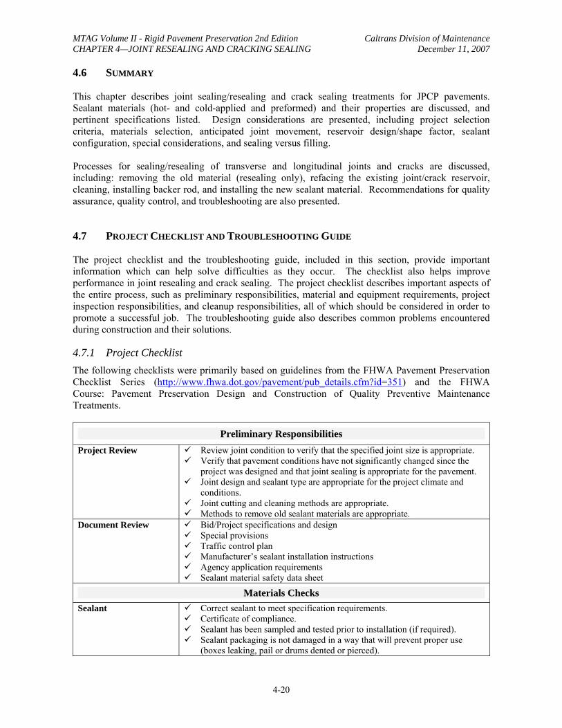
The project checklist and the troubleshooting guide, included in this section, provide important information which can help solve difficulties as they occur. The checklist also helps improve performance in joint resealing and crack sealing. The project checklist describes important aspects of the entire process, such as preliminary responsibilities, material and equipment requirements, project inspection responsibilities, and cleanup responsibilities, all of which should be considered in order to promote a successful job. The troubleshooting guide also describes common problems encountered during construction and their solutions.
4.7.1 Project Checklist The following checklists were primarily based on guidelines from the FHWA Pavement Preservation Checklist Series (http://www.fhwa.dot.gov/pavement/pub_details.cfm?id=351) and the FHWA Course: Pavement Preservation Design and Construction of Quality Preventive Maintenance Treatments.
Preliminary Responsibilities Project Review 9 Review joint condition to verify that the specified joint size is appropriate.
9 Verify that pavement conditions have not significantly changed since the project was designed and that joint sealing is appropriate for the pavement.
9 Joint design and sealant type are appropriate for the project climate and conditions.
9 Joint cutting and cleaning methods are appropriate. 9 Methods to remove old sealant materials are appropriate.
Document Review 9 Bid/Project specifications and design 9 Special provisions 9 Traffic control plan 9 Manufacturer’s sealant installation instructions 9 Agency application requirements 9 Sealant material safety data sheet
Materials Checks Sealant 9 Correct sealant to meet specification requirements.
9 Certificate of compliance. 9 Sealant has been sampled and tested prior to installation (if required). 9 Sealant packaging is not damaged in a way that will prevent proper use
(boxes leaking, pail or drums dented or pierced).
4-20
MTAG Volume II - Rigid Pavement Preservation 2nd Edition Caltrans Division of Maintenance CHAPTER 4—JOINT RESEALING AND CRACKING SEALING December 11, 2007
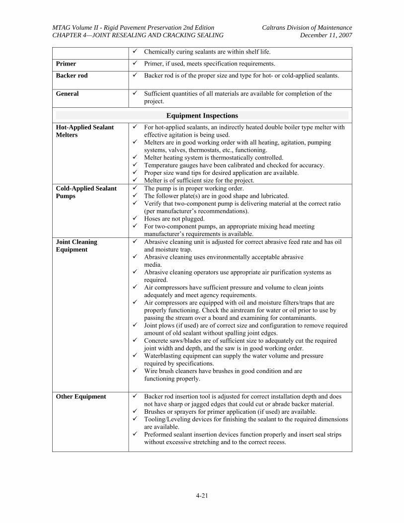
9 Chemically curing sealants are within shelf life.
Primer 9 Primer, if used, meets specification requirements.
Backer rod 9 Backer rod is of the proper size and type for hot- or cold-applied sealants.
General 9 Sufficient quantities of all materials are available for completion of the project.
Equipment Inspections Hot-Applied Sealant Melters
9 For hot-applied sealants, an indirectly heated double boiler type melter with effective agitation is being used.
9 Melters are in good working order with all heating, agitation, pumping systems, valves, thermostats, etc., functioning.
9 Melter heating system is thermostatically controlled. 9 Temperature gauges have been calibrated and checked for accuracy. 9 Proper size wand tips for desired application are available. 9 Melter is of sufficient size for the project.
Cold-Applied Sealant Pumps
9 The pump is in proper working order. 9 The follower plate(s) are in good shape and lubricated. 9 Verify that two-component pump is delivering material at the correct ratio
(per manufacturer’s recommendations). 9 Hoses are not plugged. 9 For two-component pumps, an appropriate mixing head meeting
manufacturer’s requirements is available. Joint Cleaning Equipment
9 Abrasive cleaning unit is adjusted for correct abrasive feed rate and has oil and moisture trap.
9 Abrasive cleaning uses environmentally acceptable abrasive media.
9 Abrasive cleaning operators use appropriate air purification systems as required.
9 Air compressors have sufficient pressure and volume to clean joints adequately and meet agency requirements.
9 Air compressors are equipped with oil and moisture filters/traps that are properly functioning. Check the airstream for water or oil prior to use by passing the stream over a board and examining for contaminants.
9 Joint plows (if used) are of correct size and configuration to remove required amount of old sealant without spalling joint edges.
9 Concrete saws/blades are of sufficient size to adequately cut the required joint width and depth, and the saw is in good working order.
9 Waterblasting equipment can supply the water volume and pressure required by specifications.
9 Wire brush cleaners have brushes in good condition and are functioning properly.
Other Equipment 9 Backer rod insertion tool is adjusted for correct installation depth and does not have sharp or jagged edges that could cut or abrade backer material.
9 Brushes or sprayers for primer application (if used) are available. 9 Tooling/Leveling devices for finishing the sealant to the required dimensions
are available. 9 Preformed sealant insertion devices function properly and insert seal strips
without excessive stretching and to the correct recess.
4-21
MTAG Volume II - Rigid Pavement Preservation 2nd Edition Caltrans Division of Maintenance CHAPTER 4—JOINT RESEALING AND CRACKING SEALING December 11, 2007
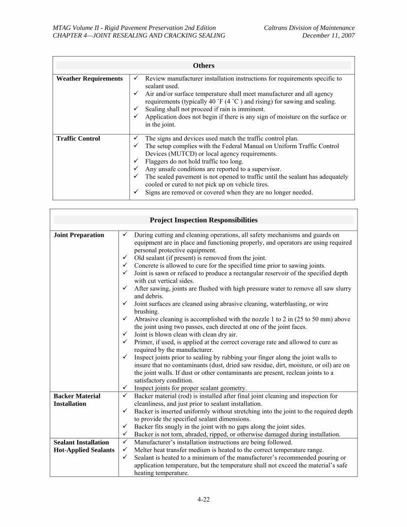
Others
Weather Requirements 9 Review manufacturer installation instructions for requirements specific to sealant used.
9 Air and/or surface temperature shall meet manufacturer and all agency requirements (typically 40 ˚F (4 ˚C ) and rising) for sawing and sealing.
9 Sealing shall not proceed if rain is imminent. 9 Application does not begin if there is any sign of moisture on the surface or
in the joint.
Traffic Control 9 The signs and devices used match the traffic control plan. 9 The setup complies with the Federal Manual on Uniform Traffic Control
Devices (MUTCD) or local agency requirements. 9 Flaggers do not hold traffic too long. 9 Any unsafe conditions are reported to a supervisor. 9 The sealed pavement is not opened to traffic until the sealant has adequately
cooled or cured to not pick up on vehicle tires. 9 Signs are removed or covered when they are no longer needed.
Project Inspection Responsibilities
Joint Preparation 9 During cutting and cleaning operations, all safety mechanisms and guards on equipment are in place and functioning properly, and operators are using required personal protective equipment.
9 Old sealant (if present) is removed from the joint. 9 Concrete is allowed to cure for the specified time prior to sawing joints. 9 Joint is sawn or refaced to produce a rectangular reservoir of the specified depth
with cut vertical sides. 9 After sawing, joints are flushed with high pressure water to remove all saw slurry
and debris. 9 Joint surfaces are cleaned using abrasive cleaning, waterblasting, or wire
brushing. 9 Abrasive cleaning is accomplished with the nozzle 1 to 2 in (25 to 50 mm) above
the joint using two passes, each directed at one of the joint faces. 9 Joint is blown clean with clean dry air. 9 Primer, if used, is applied at the correct coverage rate and allowed to cure as
required by the manufacturer. 9 Inspect joints prior to sealing by rubbing your finger along the joint walls to
insure that no contaminants (dust, dried saw residue, dirt, moisture, or oil) are on the joint walls. If dust or other contaminants are present, reclean joints to a satisfactory condition.
9 Inspect joints for proper sealant geometry. Backer Material Installation
9 Backer material (rod) is installed after final joint cleaning and inspection for cleanliness, and just prior to sealant installation.
9 Backer is inserted uniformly without stretching into the joint to the required depth to provide the specified sealant dimensions.
9 Backer fits snugly in the joint with no gaps along the joint sides. 9 Backer is not torn, abraded, ripped, or otherwise damaged during installation.
Sealant Installation Hot-Applied Sealants
9 Manufacturer’s installation instructions are being followed. 9 Melter heat transfer medium is heated to the correct temperature range. 9 Sealant is heated to a minimum of the manufacturer’s recommended pouring or
application temperature, but the temperature shall not exceed the material’s safe heating temperature.
4-22
MTAG Volume II - Rigid Pavement Preservation 2nd Edition Caltrans Division of Maintenance CHAPTER 4—JOINT RESEALING AND CRACKING SEALING December 11, 2007
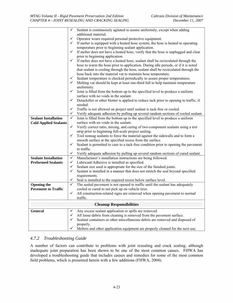
9 Sealant is continuously agitated to assure uniformity, except when adding additional material.
9 Operator wears required personal protective equipment. 9 If melter is equipped with a heated hose system, the hose is heated to operating
temperature prior to beginning sealant application. 9 If melter does not have a heated hose, verify that the hose is unplugged and clear
prior to beginning application. 9 If melter does not have a heated hose, sealant shall be recirculated through the
hose to warm the hose prior to application. During idle periods, or if it is noted that sealant is cooling through the hose, sealant shall be recirculated through the hose back into the material vat to maintain hose temperature.
9 Sealant temperature is checked periodically to assure proper temperatures. 9 Melting vat should be kept at least one-third full to help maintain temperature
uniformity. 9 Joint is filled from the bottom up to the specified level to produce a uniform
surface with no voids in the sealant. 9 Detackifier or other blotter is applied to reduce tack prior to opening to traffic, if
needed. 9 Traffic is not allowed on project until sealant is tack-free or cooled. 9 Verify adequate adhesion by pulling up several random sections of cooled sealant.
Sealant Installation Cold Applied Sealants
9 Joint is filled from the bottom up to the specified level to produce a uniform surface with no voids in the sealant.
9 Verify correct ratio, mixing, and curing of two-component sealants using a test strip prior to beginning full-scale project sealing.
9 Tool nonsag sealants to force the material against the sidewalls and to form a smooth surface at the specified recess from the surface.
9 Sealant is permitted to cure to a tack-free condition prior to opening the pavement to traffic.
9 Verify adequate adhesion by pulling up several random sections of cured sealant. Sealant Installation Preformed Sealants
9 Manufacturer’s installation instructions are being followed. 9 Lubricant/Adhesive is installed as specified. 9 Sealant size used is appropriate for the size of the finished joints. 9 Sealant is installed in a manner that does not stretch the seal beyond specified
requirements. 9 Seal is installed to the required recess below surface level.
Opening the Pavement to Traffic
9 The sealed pavement is not opened to traffic until the sealant has adequately cooled or cured to not pick up on vehicle tires.
9 All construction-related signs are removed when opening pavement to normal traffic.
Cleanup Responsibilities General 9 Any excess sealant application or spills are removed.
9 All loose debris from cleaning is removed from the pavement surface. 9 Sealant containers or other miscellaneous debris are removed and disposed of
properly. 9 Melters and other application equipment are properly cleaned for the next use.
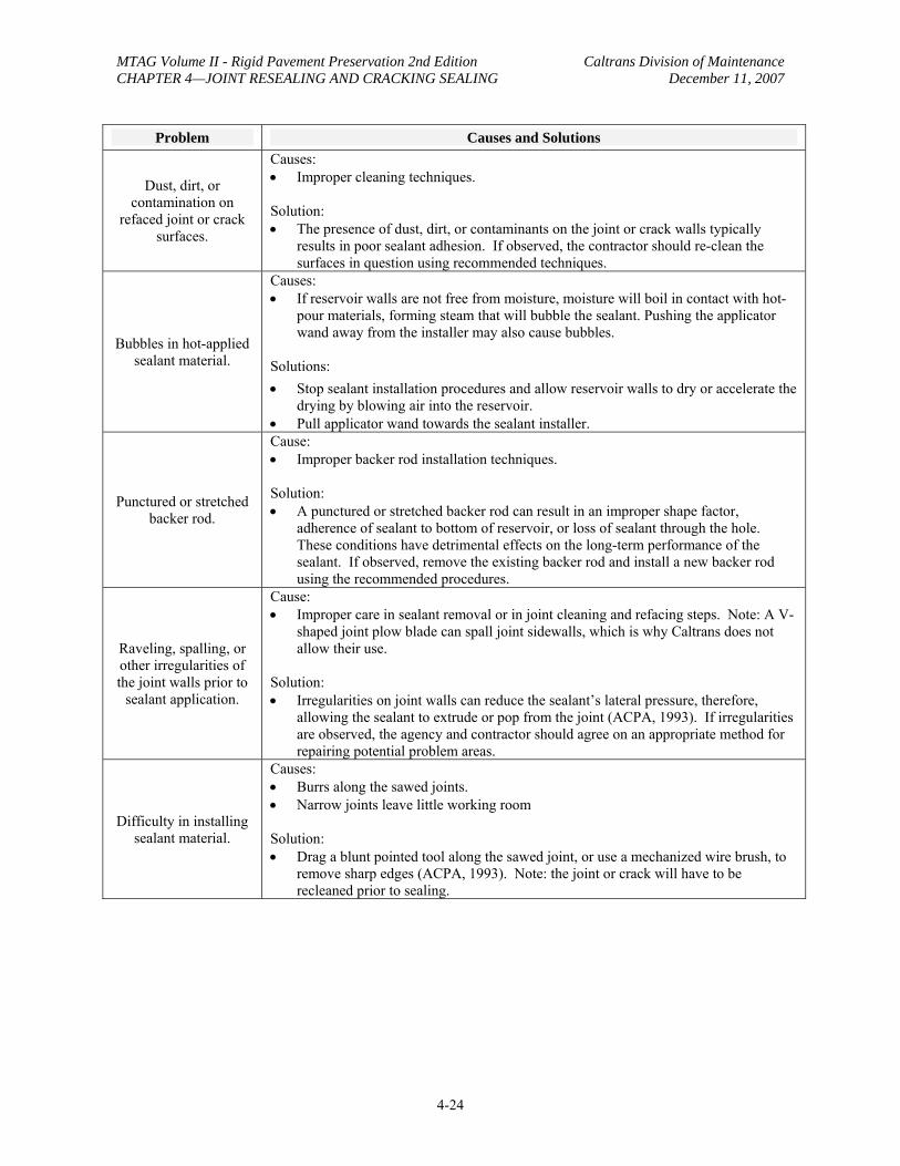
4.7.2 Troubleshooting Guide A number of factors can contribute to problems with joint resealing and crack sealing, although inadequate joint preparation has been shown to be one of the most common causes. FHWA has developed a troubleshooting guide that includes causes and remedies for some of the most common field problems, which is presented herein with a few additions (FHWA, 2004).
4-23
MTAG Volume II - Rigid Pavement Preservation 2nd Edition Caltrans Division of Maintenance CHAPTER 4—JOINT RESEALING AND CRACKING SEALING December 11, 2007
Problem Causes and Solutions
Dust, dirt, or contamination on
refaced joint or crack surfaces.
Causes: • Improper cleaning techniques.
Solution: • The presence of dust, dirt, or contaminants on the joint or crack walls typically
results in poor sealant adhesion. If observed, the contractor should re-clean the surfaces in question using recommended techniques.
Bubbles in hot-applied sealant material.
Causes: • If reservoir walls are not free from moisture, moisture will boil in contact with hot-
pour materials, forming steam that will bubble the sealant. Pushing the applicator wand away from the installer may also cause bubbles.
Solutions: • Stop sealant installation procedures and allow reservoir walls to dry or accelerate the
drying by blowing air into the reservoir. • Pull applicator wand towards the sealant installer.
Punctured or stretched backer rod.
Cause: • Improper backer rod installation techniques.
Solution: • A punctured or stretched backer rod can result in an improper shape factor,
adherence of sealant to bottom of reservoir, or loss of sealant through the hole. These conditions have detrimental effects on the long-term performance of the sealant. If observed, remove the existing backer rod and install a new backer rod using the recommended procedures.
Raveling, spalling, or other irregularities of the joint walls prior to
sealant application.
Cause: • Improper care in sealant removal or in joint cleaning and refacing steps. Note: A V-
shaped joint plow blade can spall joint sidewalls, which is why Caltrans does not allow their use.
Solution: • Irregularities on joint walls can reduce the sealant’s lateral pressure, therefore,
allowing the sealant to extrude or pop from the joint (ACPA, 1993). If irregularities are observed, the agency and contractor should agree on an appropriate method for repairing potential problem areas.
Difficulty in installing sealant material.
Causes: • Burrs along the sawed joints. • Narrow joints leave little working room
Solution: • Drag a blunt pointed tool along the sawed joint, or use a mechanized wire brush, to
remove sharp edges (ACPA, 1993). Note: the joint or crack will have to be recleaned prior to sealing.
4-24

MTAG Volume II - Rigid Pavement Preservation 2nd Edition Caltrans Division of Maintenance CHAPTER 4—JOINT RESEALING AND CRACKING SEALING December 11, 2007
Tracking of material (i.e., the transfer of
sealant material onto unwanted areas of the surface area via shoes,
tires, and so on).
Cause: • Too much sealant is being applied. • Traffic is being allowed on the sealant before the material has a chance to
sufficiently cool or cure. • The chosen sealant material is inappropriate for the climate in which it is being used.
Solution: • Reduce the amount of sealant or filler being applied. • Allow more time for material to sufficiently cool or cure (or use sufficient sand for
blotter coat). • Ensure the sealer/filler is appropriate for the climate in which it is being placed.
Bumps or irregularities in surface of tooled sealant application.
Cause: • Problem with quality of tooling equipment or quality of tooling process.
Solution: • Check tooling utensil or squeegee and ensure it is leaving the correct finish. Repair
or replace as necessary. • Ensure that tooling is being conducted within the time after application
recommended by the manufacturer. • Decrease the viscosity of the sealant (if applicable).
4.8 KEY REFERENCES
ACPA, 1993, Joint and Crack Sealing and Repair for Concrete Pavements, American Concrete Pavement Association, Skokie, IL, 1993.
Caltrans, 1998, Maintenance Manual Chapter B, Rigid Pavement, Sacramento, California, June 1998.
Caltrans, 2003, Maintenance Technical Advisory Guide, Sacramento, CA, October 2003.
Caltrans, 2004, Pavement Tech Notes – Concrete Pavement Design Overview, Sacramento, California, October 2004.
Caltrans, 2004, Pavement Tech Notes –Interim PCC Pavement Rehabilitation Guidelines, Sacramento, California, July 2004.
Caltrans, 2006, Replace Joint Seal (Existing Concrete Pavement), Standard Special Provisions, SSP 41-210, Sacramento, California, May 2006.
Caltrans, 2006, Seal Existing Concrete Pavement Joint, Standard Special Provisions, SSP 41-200, Sacramento, California, May 2006.
Caltrans, 2006, Standard Plan P1, Jointed Plain Concrete Pavement, Sacramento, California, May 2006.
Caltrans, 2006, Standard Plan P18, Concrete Pavement-Lane Schematics and isolation Joint Detail, Sacramento, California, May 2006.
Caltrans, 2006, Standard Plan P20, Concrete Pavement Joint Details, Sacramento, California, May 2006.
4-25
MTAG Volume II - Rigid Pavement Preservation 2nd Edition Caltrans Division of Maintenance CHAPTER 4—JOINT RESEALING AND CRACKING SEALING December 11, 2007
Darter, M. I. 1977. Design of Zero-Maintenance Plain Jointed Concrete Pavement, Volume I— Development of Design Procedures, FHWA-RD-77-111. Federal Highway Administration, Washington, DC, 1977.
Evans, L. D., K. L. Smith, and A. R. Romine. 1999. Materials and Procedures for the Repair of Joint Seals in Portland Cement Concrete Pavements—Manual of Practice, FHWA-RD-99-146. Federal Highway Administration, McLean, VA, 1999.
FHWA, 1985. Pavement Rehabilitation Manual, FHWA-ED-88-025. Federal Highway Administration, Washington, DC, 1985.
FHWA, 2002, Pavement Preservation Checklist Series #6, Joint Sealing Portland Cement Concrete Pavements, Publication No. FHWA-IF-03-003, FHWA, Washington DC, October 2002
FHWA, 2004, Pavement Preservation Design And Construction of Quality Preventive Maintenance Treatments, NHI Course No. 131103, Federal Highway Administration, November 2004.
Morian, D. A., N. Suthahar, and S. Stoffels. 1999. Evaluation of Rigid Pavement Joint Seal Movement, TRR 1083. Transportation Research Board, Washington, DC, 1999.
4-26