Embed Size (px)
Citation preview
Bull AIX 5L Communications Programming Concepts
AIX
86 A2 69EM 02
ORDER REFERENCE

Bull AIX 5L Communications Programming Concepts
AIX
Software
October 2005
BULL CEDOC
357 AVENUE PATTON
B.P.20845
49008 ANGERS CEDEX 01
FRANCE
86 A2 69EM 02
ORDER REFERENCE

The following copyright notice protects this book under the Copyright laws of the United States of America
and other countries which prohibit such actions as, but not limited to, copying, distributing, modifying, and
making derivative works.
Copyright Bull S.A. 1992, 2005
Printed in France
Suggestions and criticisms concerning the form, content, and presentation of
this book are invited. A form is provided at the end of this book for this purpose.
To order additional copies of this book or other Bull Technical Publications, you
are invited to use the Ordering Form also provided at the end of this book.
Trademarks and Acknowledgements
We acknowledge the right of proprietors of trademarks mentioned in this book.
AIX� is a registered trademark of International Business Machines Corporation, and is being used under
licence.
UNIX is a registered trademark in the United States of America and other countries licensed exclusively through
the Open Group.
Linux is a registered trademark of Linus Torvalds.
The information in this document is subject to change without notice. Bull will not be liable for errors contained
herein, or for incidental or consequential damages in connection with the use of this material.
Contents
About This Book . . . . . . . . . . . . . . . . . . . . . . . . . . . . . . . . vii
Highlighting . . . . . . . . . . . . . . . . . . . . . . . . . . . . . . . . . . . vii
Case-Sensitivity in AIX . . . . . . . . . . . . . . . . . . . . . . . . . . . . . . . vii
ISO 9000 . . . . . . . . . . . . . . . . . . . . . . . . . . . . . . . . . . . vii
Related Publications . . . . . . . . . . . . . . . . . . . . . . . . . . . . . . . vii
Chapter 1. Data Link Control . . . . . . . . . . . . . . . . . . . . . . . . . . . . 1
Generic Data Link Control Environment Overview . . . . . . . . . . . . . . . . . . . . . 2
Implementing GDLC Interface . . . . . . . . . . . . . . . . . . . . . . . . . . . . 4
GDLC Interface ioctl Entry Point Operations . . . . . . . . . . . . . . . . . . . . . . . 5
GDLC Special Kernel Services . . . . . . . . . . . . . . . . . . . . . . . . . . . . 7
GDLC Problem Determination . . . . . . . . . . . . . . . . . . . . . . . . . . . . 8
Data Link Control Programming and Reference Information . . . . . . . . . . . . . . . . . 11
Token-Ring Data Link Control Overview . . . . . . . . . . . . . . . . . . . . . . . . 12
DLCTOKEN Device Manager Nodes . . . . . . . . . . . . . . . . . . . . . . . . . 13
DLCTOKEN Device Manager Functions . . . . . . . . . . . . . . . . . . . . . . . . 14
DLCTOKEN Protocol Support . . . . . . . . . . . . . . . . . . . . . . . . . . . . 15
DLCTOKEN Name-Discovery Service . . . . . . . . . . . . . . . . . . . . . . . . . 16
DLCTOKEN Direct Network Services . . . . . . . . . . . . . . . . . . . . . . . . . 19
DLCTOKEN Connection Contention . . . . . . . . . . . . . . . . . . . . . . . . . . 19
Initiating DLCTOKEN Link Sessions . . . . . . . . . . . . . . . . . . . . . . . . . . 19
Stopping DLCTOKEN Link Sessions . . . . . . . . . . . . . . . . . . . . . . . . . 20
DLCTOKEN Programming Interfaces . . . . . . . . . . . . . . . . . . . . . . . . . 20
IEEE 802.3 Ethernet Data Link Control Overview . . . . . . . . . . . . . . . . . . . . . 24
DLC8023 Device Manager Nodes . . . . . . . . . . . . . . . . . . . . . . . . . . 25
DLC8023 Device Manager Functions . . . . . . . . . . . . . . . . . . . . . . . . . 25
DLC8023 Protocol Support . . . . . . . . . . . . . . . . . . . . . . . . . . . . . 26
DLC8023 Name-Discovery Services . . . . . . . . . . . . . . . . . . . . . . . . . 27
DLC8023 Direct Network Services . . . . . . . . . . . . . . . . . . . . . . . . . . 30
DLC8023 Connection Contention . . . . . . . . . . . . . . . . . . . . . . . . . . . 30
DLC8023 Link Sessions . . . . . . . . . . . . . . . . . . . . . . . . . . . . . . 30
DLC8023 Programming Interfaces . . . . . . . . . . . . . . . . . . . . . . . . . . 31
Standard Ethernet Data Link Control Overview . . . . . . . . . . . . . . . . . . . . . . 34
DLCETHER Device Manager Nodes . . . . . . . . . . . . . . . . . . . . . . . . . 35
DLCETHER Device Manager Functions . . . . . . . . . . . . . . . . . . . . . . . . 35
DLCETHER Protocol Support . . . . . . . . . . . . . . . . . . . . . . . . . . . . 36
DLCETHER Name-Discovery Services . . . . . . . . . . . . . . . . . . . . . . . . 37
DLCETHER Direct Network Services . . . . . . . . . . . . . . . . . . . . . . . . . 40
DLCETHER Connection Contention . . . . . . . . . . . . . . . . . . . . . . . . . . 40
DLCETHER Link Session Initiation . . . . . . . . . . . . . . . . . . . . . . . . . . 40
DLCETHER Link Session Termination . . . . . . . . . . . . . . . . . . . . . . . . . 41
DLCETHER Programming Interfaces . . . . . . . . . . . . . . . . . . . . . . . . . 41
Synchronous Data Link Control Overview . . . . . . . . . . . . . . . . . . . . . . . 44
DLCSDLC Device Manager Functions . . . . . . . . . . . . . . . . . . . . . . . . . 45
DLCSDLC Protocol Support . . . . . . . . . . . . . . . . . . . . . . . . . . . . 45
DLCSDLC Programming Interfaces . . . . . . . . . . . . . . . . . . . . . . . . . . 48
DLCSDLC Asynchronous Function Subroutine Calls . . . . . . . . . . . . . . . . . . . . 51
Qualified Logical Link Control (DLCQLLC) Overview . . . . . . . . . . . . . . . . . . . 51
Data Link Control FDDI (DLC FDDI) Overview . . . . . . . . . . . . . . . . . . . . . . 57
DLC FDDI Device Manager Nodes . . . . . . . . . . . . . . . . . . . . . . . . . . 58
DLC FDDI Device Manager Functions . . . . . . . . . . . . . . . . . . . . . . . . . 58
DLC FDDI Protocol Support . . . . . . . . . . . . . . . . . . . . . . . . . . . . 59
DLC FDDI Name-Discovery Services . . . . . . . . . . . . . . . . . . . . . . . . . 60
© Copyright IBM Corp. 1994, 2005 iii
DLC FDDI Direct Network Services . . . . . . . . . . . . . . . . . . . . . . . . . . 63
DLC FDDI Connection Contention . . . . . . . . . . . . . . . . . . . . . . . . . . 63
DLC FDDI Link Sessions . . . . . . . . . . . . . . . . . . . . . . . . . . . . . . 63
DLC FDDI Programming Interfaces . . . . . . . . . . . . . . . . . . . . . . . . . . 64
Chapter 2. Data Link Provider Interface Implementation . . . . . . . . . . . . . . . . . 69
Primitive Implementation Specifics . . . . . . . . . . . . . . . . . . . . . . . . . . 69
Packet Format Registration Specifics . . . . . . . . . . . . . . . . . . . . . . . . . 69
Address Resolution Routine Registration Specifics . . . . . . . . . . . . . . . . . . . . 70
ioctl Specifics . . . . . . . . . . . . . . . . . . . . . . . . . . . . . . . . . . 71
Dynamic Route Discovery . . . . . . . . . . . . . . . . . . . . . . . . . . . . . 73
DRD Configuration . . . . . . . . . . . . . . . . . . . . . . . . . . . . . . . . 73
Connectionless Mode Only DLPI Driver versus Connectionless/Connection-Oriented DLPI Driver . . . 73
DLPI Primitives . . . . . . . . . . . . . . . . . . . . . . . . . . . . . . . . . 74
Obtaining Copies of the DLPI Specifications . . . . . . . . . . . . . . . . . . . . . . 76
Chapter 3. New Database Manager . . . . . . . . . . . . . . . . . . . . . . . . . 77
Using NDBM Subroutines . . . . . . . . . . . . . . . . . . . . . . . . . . . . . 77
Diagnosing NDBM Problems . . . . . . . . . . . . . . . . . . . . . . . . . . . . 77
List of NDBM and DBM Programming References . . . . . . . . . . . . . . . . . . . . 77
Chapter 4. eXternal Data Representation . . . . . . . . . . . . . . . . . . . . . . . 79
eXternal Data Representation Overview for Programming . . . . . . . . . . . . . . . . . . 79
XDR Subroutine Format . . . . . . . . . . . . . . . . . . . . . . . . . . . . . . 81
XDR Library . . . . . . . . . . . . . . . . . . . . . . . . . . . . . . . . . . 81
XDR Language Specification . . . . . . . . . . . . . . . . . . . . . . . . . . . . 82
XDR Data Types . . . . . . . . . . . . . . . . . . . . . . . . . . . . . . . . . 84
List of XDR Programming References . . . . . . . . . . . . . . . . . . . . . . . . . 94
XDR Library Filter Primitives . . . . . . . . . . . . . . . . . . . . . . . . . . . . 95
XDR Non-Filter Primitives . . . . . . . . . . . . . . . . . . . . . . . . . . . . . 98
Passing Linked Lists Using XDR Example . . . . . . . . . . . . . . . . . . . . . . . 100
Using an XDR Data Description Example . . . . . . . . . . . . . . . . . . . . . . . 102
Showing the Justification for Using XDR Example . . . . . . . . . . . . . . . . . . . . 103
Using XDR Example . . . . . . . . . . . . . . . . . . . . . . . . . . . . . . . 105
Using XDR Array Examples . . . . . . . . . . . . . . . . . . . . . . . . . . . . 106
Using an XDR Discriminated Union Example . . . . . . . . . . . . . . . . . . . . . . 107
Showing the Use of Pointers in XDR Example . . . . . . . . . . . . . . . . . . . . . 108
Chapter 5. Network Computing System . . . . . . . . . . . . . . . . . . . . . . . 109
Remote Procedure Call Runtime Library . . . . . . . . . . . . . . . . . . . . . . . 109
The Location Broker . . . . . . . . . . . . . . . . . . . . . . . . . . . . . . . 110
Chapter 6. Network Information Services (NIS and NIS+) . . . . . . . . . . . . . . . . 115
List of NIS and NIS+ Programming References . . . . . . . . . . . . . . . . . . . . . 115
Chapter 7. Network Management . . . . . . . . . . . . . . . . . . . . . . . . . 119
Simple Network Management Protocol . . . . . . . . . . . . . . . . . . . . . . . . 119
Management Information Base . . . . . . . . . . . . . . . . . . . . . . . . . . . 120
Terminology Related to Management Information Base Variables . . . . . . . . . . . . . . 122
Working with Management Information Base Variables . . . . . . . . . . . . . . . . . . 123
Management Information Base Database . . . . . . . . . . . . . . . . . . . . . . . 123
How a Manager Functions . . . . . . . . . . . . . . . . . . . . . . . . . . . . . 125
How an Agent Functions . . . . . . . . . . . . . . . . . . . . . . . . . . . . . 125
List of SNMP Agent Programming References . . . . . . . . . . . . . . . . . . . . . 127
SMUX Error Logging Subroutines Examples . . . . . . . . . . . . . . . . . . . . . . 128
iv Communications Programming Concepts
Chapter 8. Remote Procedure Call . . . . . . . . . . . . . . . . . . . . . . . . . 131
RPC Model . . . . . . . . . . . . . . . . . . . . . . . . . . . . . . . . . . 132
RPC Message Protocol . . . . . . . . . . . . . . . . . . . . . . . . . . . . . . 133
RPC Authentication . . . . . . . . . . . . . . . . . . . . . . . . . . . . . . . 138
RPC Port Mapper Program . . . . . . . . . . . . . . . . . . . . . . . . . . . . 144
Programming in RPC . . . . . . . . . . . . . . . . . . . . . . . . . . . . . . 146
RPC Features . . . . . . . . . . . . . . . . . . . . . . . . . . . . . . . . . 153
RPC Language . . . . . . . . . . . . . . . . . . . . . . . . . . . . . . . . . 155
rpcgen Protocol Compiler . . . . . . . . . . . . . . . . . . . . . . . . . . . . . 160
List of RPC Programming References . . . . . . . . . . . . . . . . . . . . . . . . 162
Using UNIX Authentication Example . . . . . . . . . . . . . . . . . . . . . . . . . 166
DES Authentication Example . . . . . . . . . . . . . . . . . . . . . . . . . . . . 168
Using the Highest Layer of RPC Example . . . . . . . . . . . . . . . . . . . . . . . 170
Using the Intermediate Layer of RPC Example . . . . . . . . . . . . . . . . . . . . . 170
Using the Lowest Layer of RPC Example . . . . . . . . . . . . . . . . . . . . . . . 171
Showing How RPC Passes Arbitrary Data Types Example . . . . . . . . . . . . . . . . . 175
Using Multiple Program Versions Example . . . . . . . . . . . . . . . . . . . . . . . 176
Broadcasting a Remote Procedure Call Example . . . . . . . . . . . . . . . . . . . . 177
Using the select Subroutine Example . . . . . . . . . . . . . . . . . . . . . . . . . 178
rcp Process on TCP Example . . . . . . . . . . . . . . . . . . . . . . . . . . . 178
RPC Callback Procedures Example . . . . . . . . . . . . . . . . . . . . . . . . . 180
RPC Language ping Program Example . . . . . . . . . . . . . . . . . . . . . . . . 183
Converting Local Procedures into Remote Procedures Example . . . . . . . . . . . . . . . 184
Generating XDR Routines Example . . . . . . . . . . . . . . . . . . . . . . . . . 187
Chapter 9. Sockets . . . . . . . . . . . . . . . . . . . . . . . . . . . . . . . 191
Sockets Overview . . . . . . . . . . . . . . . . . . . . . . . . . . . . . . . . 191
Sockets Interface . . . . . . . . . . . . . . . . . . . . . . . . . . . . . . . . 193
Socket Subroutines . . . . . . . . . . . . . . . . . . . . . . . . . . . . . . . 194
Socket Header Files . . . . . . . . . . . . . . . . . . . . . . . . . . . . . . . 195
Socket Communication Domains . . . . . . . . . . . . . . . . . . . . . . . . . . 196
Socket Addresses . . . . . . . . . . . . . . . . . . . . . . . . . . . . . . . . 198
Socket Types and Protocols . . . . . . . . . . . . . . . . . . . . . . . . . . . . 201
Socket Creation . . . . . . . . . . . . . . . . . . . . . . . . . . . . . . . . 203
Binding Names to Sockets . . . . . . . . . . . . . . . . . . . . . . . . . . . . . 203
Socket Connections . . . . . . . . . . . . . . . . . . . . . . . . . . . . . . . 205
Socket Options . . . . . . . . . . . . . . . . . . . . . . . . . . . . . . . . . 208
Socket Data Transfer . . . . . . . . . . . . . . . . . . . . . . . . . . . . . . 208
Socket Shutdown . . . . . . . . . . . . . . . . . . . . . . . . . . . . . . . . 210
IP Multicasts . . . . . . . . . . . . . . . . . . . . . . . . . . . . . . . . . . 211
Network Address Translation . . . . . . . . . . . . . . . . . . . . . . . . . . . . 212
Domain Name Resolution . . . . . . . . . . . . . . . . . . . . . . . . . . . . . 216
Socket Examples . . . . . . . . . . . . . . . . . . . . . . . . . . . . . . . . 218
Socketpair Communication Example . . . . . . . . . . . . . . . . . . . . . . . . . 219
Reading Internet Datagrams Example Program . . . . . . . . . . . . . . . . . . . . . 219
Sending Internet Datagrams Example Program . . . . . . . . . . . . . . . . . . . . . 220
Reading UNIX Datagrams Example Program . . . . . . . . . . . . . . . . . . . . . . 221
Sending UNIX Datagrams Example Program . . . . . . . . . . . . . . . . . . . . . . 221
Initiating Internet Stream Connections Example Program . . . . . . . . . . . . . . . . . 222
Accepting Internet Stream Connections Example Program . . . . . . . . . . . . . . . . . 223
Checking for Pending Connections Example Program . . . . . . . . . . . . . . . . . . 224
Initiating UNIX Stream Connections Example Program . . . . . . . . . . . . . . . . . . 225
Accepting UNIX Stream Connections Example Program . . . . . . . . . . . . . . . . . . 226
Sending Data on an ATM Socket PVC Client Example Program . . . . . . . . . . . . . . . 227
Receiving Data on an ATM Socket PVC Server Example Program . . . . . . . . . . . . . . 228
Sending Data on an ATM Socket Rate-Enforced SVC Client Example Program . . . . . . . . . 229
Contents v
Receiving Data on an ATM Socket Rate-Enforced SVC Server Example Program . . . . . . . . 233
Sending Data on an ATM Socket SVC Client Example Program . . . . . . . . . . . . . . . 235
Receiving Data on an ATM Socket SVC Server Example Program . . . . . . . . . . . . . . 238
Receiving Packets Over Ethernet Example Program . . . . . . . . . . . . . . . . . . . 241
Sending Packets Over Ethernet Example Program . . . . . . . . . . . . . . . . . . . . 243
Analyzing Packets Over the Network Example Program . . . . . . . . . . . . . . . . . . 245
List of Socket Programming References . . . . . . . . . . . . . . . . . . . . . . . . 246
Chapter 10. STREAMS . . . . . . . . . . . . . . . . . . . . . . . . . . . . . . 249
STREAMS Introduction . . . . . . . . . . . . . . . . . . . . . . . . . . . . . . 249
Benefits and Features of STREAMS . . . . . . . . . . . . . . . . . . . . . . . . . 252
STREAMS Flow Control . . . . . . . . . . . . . . . . . . . . . . . . . . . . . 254
STREAMS Synchronization . . . . . . . . . . . . . . . . . . . . . . . . . . . . 255
Using STREAMS . . . . . . . . . . . . . . . . . . . . . . . . . . . . . . . . 262
STREAMS Tunable Parameters . . . . . . . . . . . . . . . . . . . . . . . . . . . 263
streamio (STREAMS ioctl) Operations . . . . . . . . . . . . . . . . . . . . . . . . 265
Building STREAMS . . . . . . . . . . . . . . . . . . . . . . . . . . . . . . . 265
STREAMS Messages . . . . . . . . . . . . . . . . . . . . . . . . . . . . . . 268
Put and Service Procedures . . . . . . . . . . . . . . . . . . . . . . . . . . . . 271
STREAMS Drivers and Modules . . . . . . . . . . . . . . . . . . . . . . . . . . 272
log Device Driver . . . . . . . . . . . . . . . . . . . . . . . . . . . . . . . . 275
Configuring Drivers and Modules in the Portable Streams Environment . . . . . . . . . . . . 277
An Asynchronous Protocol STREAMS Example . . . . . . . . . . . . . . . . . . . . . 280
Differences Between Portable Streams Environment and V.4 STREAMS . . . . . . . . . . . . 285
List of Streams Commands . . . . . . . . . . . . . . . . . . . . . . . . . . . . 286
List of STREAMS Programming References . . . . . . . . . . . . . . . . . . . . . . 287
Transport Service Library Interface Overview . . . . . . . . . . . . . . . . . . . . . . 289
Chapter 11. Transmission Control Protocol/Internet Protocol . . . . . . . . . . . . . . 293
DHCP Server API . . . . . . . . . . . . . . . . . . . . . . . . . . . . . . . . 293
Dynamic Load API . . . . . . . . . . . . . . . . . . . . . . . . . . . . . . . 299
Service Location Protocol (SLP) APIs . . . . . . . . . . . . . . . . . . . . . . . . 303
Lists of Programming References . . . . . . . . . . . . . . . . . . . . . . . . . . 307
Chapter 12. Packet Capture Library . . . . . . . . . . . . . . . . . . . . . . . . 311
Packet Capture Library Overview . . . . . . . . . . . . . . . . . . . . . . . . . . 311
Packet Capture Library Subroutines . . . . . . . . . . . . . . . . . . . . . . . . . 312
Packet Capture Library Header Files . . . . . . . . . . . . . . . . . . . . . . . . . 312
Packet Capture Library Data Structures . . . . . . . . . . . . . . . . . . . . . . . . 312
Packet Capture Library Filter Expressions . . . . . . . . . . . . . . . . . . . . . . . 313
Sample 1: Capturing Packet Data and Printing It in Binary Form to the Screen . . . . . . . . . 315
Sample 2: Capturing Packet Data and Saving It to a File for Processing Later . . . . . . . . . 318
Sample 3: Reading Previously Captured Packet Data from a Savefile and Processing It . . . . . . 322
Index . . . . . . . . . . . . . . . . . . . . . . . . . . . . . . . . . . . . 327
vi Communications Programming Concepts
About This Book
This book provides programmers with complete information about creating and implementing
communications programs for the AIX® operating system. Users of this book need to be familiar with the C
programming language. Programmers can use this book to gain knowledge of DLCs (Data Link Controls),
DLPI (Data Link Provider Interface), NDBM (new Database Manager), XDR (eXternal Data
Representation), NCS (Network Computing System), NIS (Network Information Services), SNMP (Simple
Network Management Protocol), RPC (Remote Procedure Call), Sockets, STREAMS, and TCP/IP
(Transmission Control Protocol/Internet Protocol).
Highlighting
The following highlighting conventions are used in this book:
Bold Identifies commands, subroutines, keywords, files,
structures, directories, and other items whose names are
predefined by the system. Also identifies graphical objects
such as buttons, labels, and icons that the user selects.
Italics Identifies parameters whose actual names or values are to
be supplied by the user.
Monospace Identifies examples of specific data values, examples of
text similar to what you might see displayed, examples of
portions of program code similar to what you might write
as a programmer, messages from the system, or
information you should actually type.
Case-Sensitivity in AIX
Everything in the AIX operating system is case-sensitive, which means that it distinguishes between
uppercase and lowercase letters. For example, you can use the ls command to list files. If you type LS, the
system responds that the command is ″not found.″ Likewise, FILEA, FiLea, and filea are three distinct file
names, even if they reside in the same directory. To avoid causing undesirable actions to be performed,
always ensure that you use the correct case.
ISO 9000
ISO 9000 registered quality systems were used in the development and manufacturing of this product.
Related Publications
The following books contain information about or related to communications:
v AIX 5L Version 5.3 System User’s Guide: Communications and Networks
v AIX 5L Version 5.3 System Management Guide: Communications and Networks
v AIX 5L Version 5.3 Technical Reference: Communications Volume 1
v AIX 5L Version 5.3 Technical Reference: Communications Volume 2
v AIX 5L Version 5.3 General Programming Concepts: Writing and Debugging Programs
v AIX 5L Version 5.3 Kernel Extensions and Device Support Programming Concepts
v AIX 5L Version 5.3 Technical Reference: Base Operating System and Extensions Volume 1
v AIX 5L Version 5.3 Technical Reference: Base Operating System and Extensions Volume 2
© Copyright IBM Corp. 1994, 2005 vii

viii Communications Programming Concepts
Chapter 1. Data Link Control
Generic data link control (GDLC) defines a generic interface with a common set of commands that allows
application and kernel users to control DLC device managers within the operating system.
This chapter discusses the following topics:
v “Generic Data Link Control Environment Overview” on page 2
v “Implementing GDLC Interface” on page 4
v “GDLC Interface ioctl Entry Point Operations” on page 5
v “GDLC Special Kernel Services” on page 7
v “GDLC Problem Determination” on page 8
v “Data Link Control Programming and Reference Information” on page 11
v “Token-Ring Data Link Control Overview” on page 12
v “DLCTOKEN Device Manager Nodes” on page 13
v “DLCTOKEN Device Manager Functions” on page 14
v “DLCTOKEN Protocol Support” on page 15
v “DLCTOKEN Name-Discovery Service” on page 16
v “DLCTOKEN Direct Network Services” on page 19
v “DLCTOKEN Connection Contention” on page 19
v “Initiating DLCTOKEN Link Sessions” on page 19
v “Stopping DLCTOKEN Link Sessions” on page 20
v “DLCTOKEN Programming Interfaces” on page 20
v “IEEE 802.3 Ethernet Data Link Control Overview” on page 24
v “DLC8023 Device Manager Nodes” on page 25
v “DLC8023 Device Manager Functions” on page 25
v “DLC8023 Protocol Support” on page 26
v “DLC8023 Name-Discovery Services” on page 27
v “DLC8023 Direct Network Services” on page 30
v “DLC8023 Connection Contention” on page 30
v “DLC8023 Link Sessions” on page 30
v “DLC8023 Programming Interfaces” on page 31
v “Standard Ethernet Data Link Control Overview” on page 34
v “DLCETHER Device Manager Nodes” on page 35
v “DLCETHER Device Manager Functions” on page 35
v “DLCETHER Protocol Support” on page 36
v “DLCETHER Name-Discovery Services” on page 37
v “DLCETHER Direct Network Services” on page 40
v “DLCETHER Connection Contention” on page 40
v “DLCETHER Link Session Initiation” on page 40
v “DLCETHER Link Session Termination” on page 41
v “DLCETHER Programming Interfaces” on page 41
v “Synchronous Data Link Control Overview” on page 44
v “DLCSDLC Device Manager Functions” on page 45
v “DLCSDLC Protocol Support” on page 45
v “DLCSDLC Programming Interfaces” on page 48
© Copyright IBM Corp. 1994, 2005 1
v “DLCSDLC Asynchronous Function Subroutine Calls” on page 51
v “Qualified Logical Link Control (DLCQLLC) Overview” on page 51
v “Data Link Control FDDI (DLC FDDI) Overview” on page 57
v “DLC FDDI Device Manager Nodes” on page 58
v “DLC FDDI Device Manager Functions” on page 58
v “DLC FDDI Protocol Support” on page 59
v “DLC FDDI Name-Discovery Services” on page 60
v “DLC FDDI Direct Network Services” on page 63
v “DLC FDDI Connection Contention” on page 63
v “DLC FDDI Link Sessions” on page 63
v “DLC FDDI Programming Interfaces” on page 64
Generic Data Link Control Environment Overview
Generic data link control (GDLC) defines a generic interface with a common set of commands that allows
application and kernel users to control DLC device managers within the operating system.
The GDLC interface specifies requirements for entry point definitions, functions provided, and data
structures for all DLC device managers. DLCs that conform to the GDLC interface include:
v “Token-Ring Data Link Control Overview” on page 12
v “IEEE 802.3 Ethernet Data Link Control Overview” on page 24
v “Standard Ethernet Data Link Control Overview” on page 34
v “Synchronous Data Link Control Overview” on page 44
v “Qualified Logical Link Control (DLCQLLC) Overview” on page 51
v “Data Link Control FDDI (DLC FDDI) Overview” on page 57
DLC device managers perform higher layer protocols and functions beyond the scope of a kernel device
driver. However, the managers reside within the kernel for maximum performance and use a kernel device
driver for their I/O requests to the adapter. A DLC user is located above or within the kernel.
SDLC and IEEE 802.2 data link control are examples of DLC device managers. Each DLC device
manager operates with a specific device driver or set of device drivers. SDLC, for example, operates with
the Multiprotocol device driver for the system’s product and its associated adapter.
For more information about the GDLC environment, see:
v “Implementing GDLC Interface” on page 4
v “GDLC Interface ioctl Entry Point Operations” on page 5
v “GDLC Special Kernel Services” on page 7
v “GDLC Problem Determination” on page 8
v “Data Link Control Programming and Reference Information” on page 11
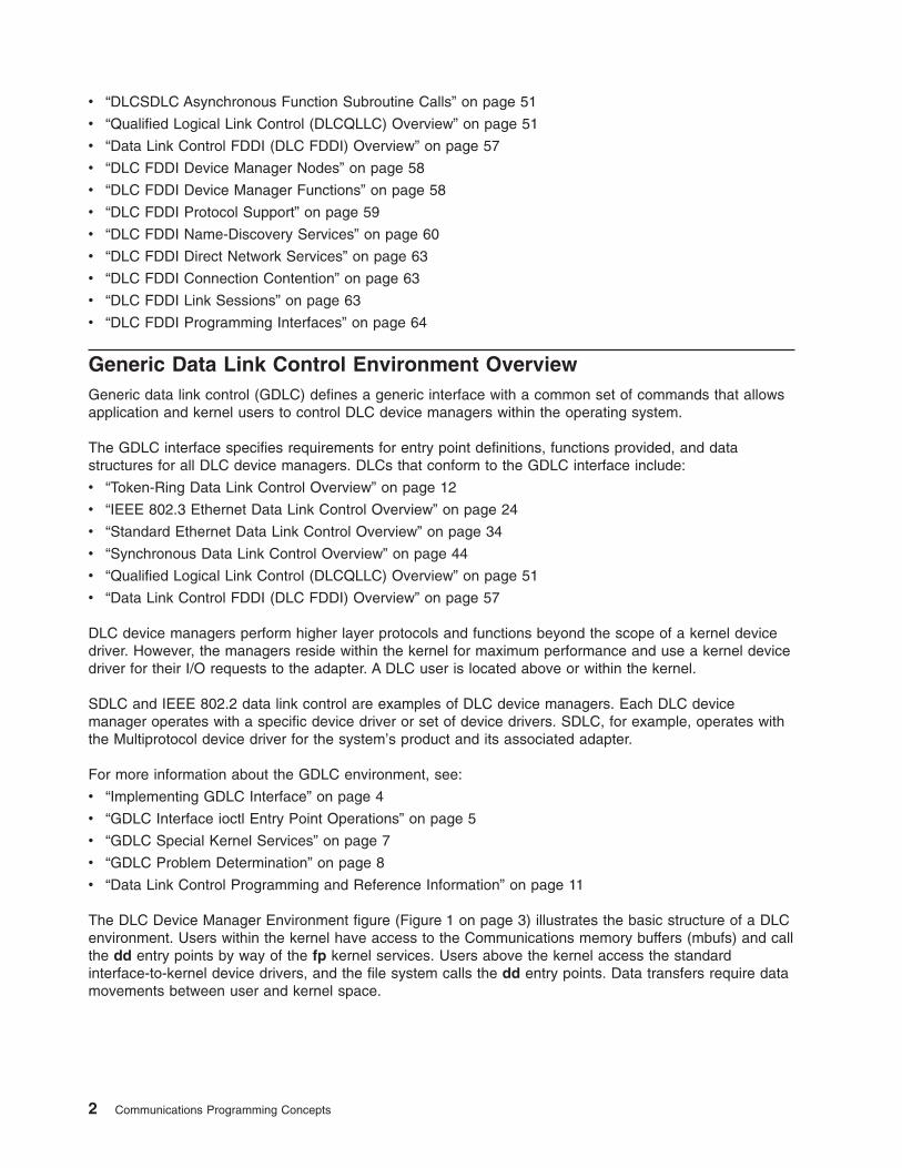
The DLC Device Manager Environment figure (Figure 1 on page 3) illustrates the basic structure of a DLC
environment. Users within the kernel have access to the Communications memory buffers (mbufs) and call
the dd entry points by way of the fp kernel services. Users above the kernel access the standard
interface-to-kernel device drivers, and the file system calls the dd entry points. Data transfers require data
movements between user and kernel space.
2 Communications Programming Concepts
The components of the DLC device manager environment are as follows:
application user Resides above the kernel as an application or access method.
kernel user Resides within the kernel as a kernel process or device manager.
file I/O subsystem Converts the file-descriptor and file-pointer subroutines to file-pointer
accesses of the switch table.
buffer pool Provides data-buffer services for the communications subsystem.
comm I/O device driver Controls hardware adapter input/output (I/O) and direct memory access
(DMA) registers, and routes receive packets to multiple DLCs.
adapter Attaches to the communications media.
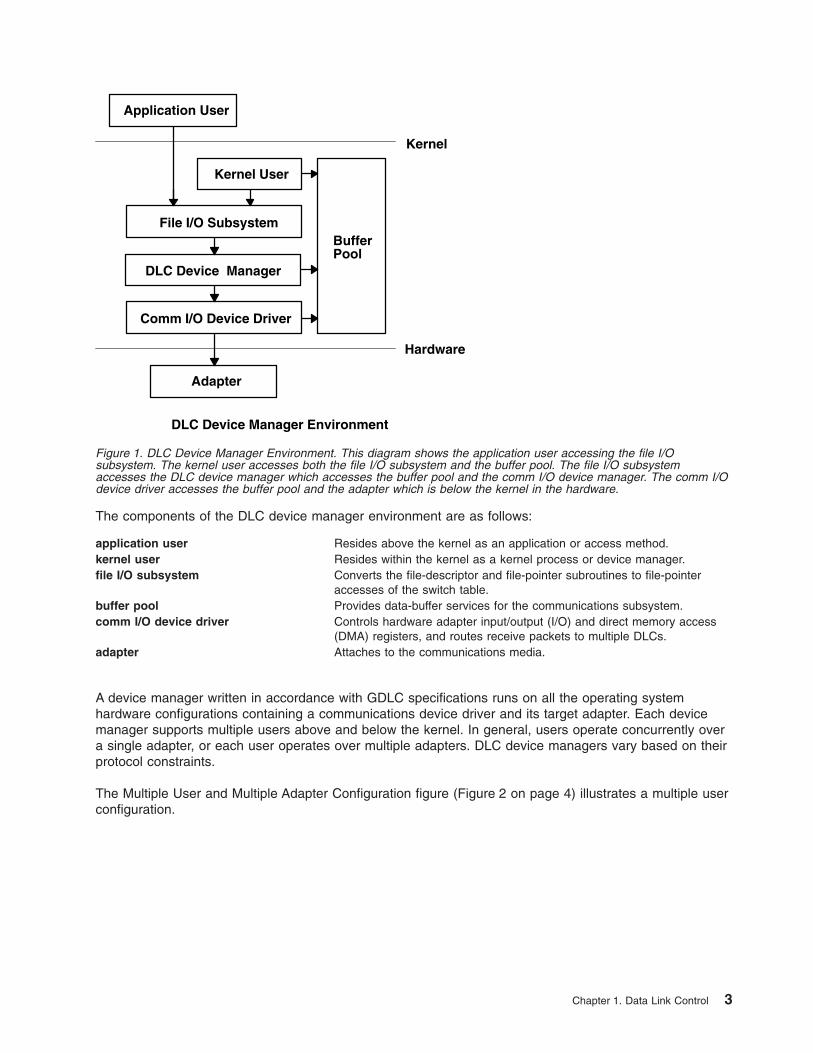
A device manager written in accordance with GDLC specifications runs on all the operating system
hardware configurations containing a communications device driver and its target adapter. Each device
manager supports multiple users above and below the kernel. In general, users operate concurrently over
a single adapter, or each user operates over multiple adapters. DLC device managers vary based on their
protocol constraints.
The Multiple User and Multiple Adapter Configuration figure (Figure 2 on page 4) illustrates a multiple user
configuration.
Application User
Kernel User
File I/O Subsystem
DLC Device Manager
Comm I/O Device Driver
Adapter
BufferPool
Hardware
DLC Device Manager Environment
Kernel
Figure 1. DLC Device Manager Environment. This diagram shows the application user accessing the file I/O
subsystem. The kernel user accesses both the file I/O subsystem and the buffer pool. The file I/O subsystem
accesses the DLC device manager which accesses the buffer pool and the comm I/O device manager. The comm I/O
device driver accesses the buffer pool and the adapter which is below the kernel in the hardware.
Chapter 1. Data Link Control 3
Meeting the GDLC Criteria
A GDLC interface must meet the following criteria:
v Be flexible and accessible to both application and kernel users.
v Have multiple user and multiple adapter capability, allowing protocols to take advantage of multiple
sessions and ports.
v Support connection-oriented and connectionless DLC device managers.
v For special requirements beyond the scope of the DLC device manager in use, must allow transparent
data transfer.
Implementing GDLC Interface
Each data link control (DLC) device manager operates in the kernel as a standard /dev entry of a
multiplexed device manager for a specified protocol. For an adapter not in use by DLC, each open
subroutine to a DLC device manager creates a kernel process. An open subroutine is also issued to the
target adapter’s device handler. If needed, issue additional open subroutines for multiple DLC adapter
ports of the same protocol. Any open subroutine targeting the same port does not create additional kernel
processes, but links the open subroutine with the existing process. Each active port always uses one
kernel process.
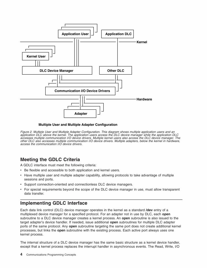
The internal structure of a DLC device manager has the same basic structure as a kernel device handler,
except that a kernel process replaces the interrupt handler in asynchronous events. The Read, Write, I/O
Application User
Kernel User
Adapter
Kernel
Application DLC
Other DLCDLC Device Manager
Communication I/O Device Drivers
Hardware
Multiple User and Multiple Adapter Configuration
Figure 2. Multiple User and Multiple Adapter Configuration. This diagram shows multiple application users and an
application DLC above the kernel. The application users access the DLC device manager while the application DLC
accesses multiple communication I/O device drivers. Multiple kernel users also access the DLC device manager. The
other DLC also accesses multiple communication I/O device drivers. Multiple adapters, below the kernel in hardware,
access the communication I/O device drivers.
4 Communications Programming Concepts
Control, and Select blocks function as set forth in the Standard Kernel Device Manager (Figure 3) figure.
Use the information in the following table to add an installed DLC.
Note: A data link control (DLC) must be installed before adding it to the system.
Adding an Installed DLC Task
Web-based System
Manager
wsm, then select network
-OR-
Task SMIT Fast Path Command or File
Adding an Installed DLC Choose one (depending on type):
smit cmddlc_sdlc
smit cmddlc_token
smit cmddlc_qllc
smit cmddlc_ether(see note)
smit cmddlc_fddi
mkdev
Note: The SMIT fast path to add an Ethernet device manager includes both Standard Ethernet and IEEE
802.3 Ethernet device managers.
GDLC Interface ioctl Entry Point Operations
The generic data link control (GDLC) interface supports the following ioctl subroutine operations:
DLC_ENABLE_SAP Enables a service access point (SAP). See “Service Access Points” on page 6.
DLC_DISABLE_SAP Disables a SAP. See “Service Access Points” on page 6.
DLC_START_LS Starts a link station (LS) on a particular SAP as a caller or listener. See “Link
Stations” on page 6.
DLC_HALT_LS Halts an LS. See “Link Stations” on page 6.
DLC_TRACE Traces a link station’s activity for short or long activities. See “Testing and
Tracing Links” on page 7.
DLC_CONTACT Contacts a remote station for a particular local link station.
DLC_TEST Tests the link to a remote for a particular local link station. “Testing and Tracing
Links” on page 7.
dlcwrite dlcioctl dlcread dlcselect
Write I/OControl
To the Device Handler From the Device Handler
From the User
Read InterruptHandler
Select
Standard Kernel Device Manager
Figure 3. Standard Kernel Device Manager. This diagram shows the dlcwrite, dlcioctl, dlcread, and dlcselect (from the
user) traveling to write, I/O control, read and select, respectively (in the standard kernel device manager). The interrupt
handler gets input from the device handler and its output is directed to select, read, and I/O control. The output of I/O
control and write goes to the device handler.
Chapter 1. Data Link Control 5
DLC_ALTER Alters a link station’s configuration parameters.
DLC_QUERY_SAP Queries statistics of a particular SAP.
DLC_QUERY_LS Queries statistics of a particular link station.
DLC_ENTER_LBUSY Enters local-busy mode on a particular link station. See “Local-Busy Mode” on
page 7.
DLC_EXIT_LBUSY Exits local-busy mode on a particular link station. See “Local-Busy Mode” on
page 7.
DLC_ENTER_SHOLD Enters short-hold mode on a particular link station. See “Short-Hold Mode” on
page 7.
DLC_EXIT_SHOLD Exits short-hold mode on a particular link station. See “Short-Hold Mode” on
page 7.
DLC_GET_EXCEP Returns asynchronous exception notifications to the application user.
Note: This ioctl subroutine operation is not used by the kernel user since all
exception conditions are passed to the kernel user by way of their exception
handler.
DLC_ADD_GRP Adds a group or multicast receive address to a port.
DLC_ADD_FUNC_ADDR Adds a group or multicast receive functional address to a port.
DLC_DEL_FUNC_ADDR Removes a group or multicast receive functional address from a port.
DLC_DEL_GRP Removes a group or multicast address from a port.
IOCINFO Returns a structure that describes the GDLC device manager. See the
/usr/include/sys/devinfo.h file format for more information.
Service Access Points
A service access point (SAP) identifies a particular user service that sends and receives a specific class of
data. This user service allows different classes of data to be routed separately to their corresponding
service handlers. Those DLCs that support multiple concurrent SAPs have addresses known as
destination SAP and source SAP embedded in their packet headers. DLCs that can only support a single
SAP do not need or use SAP addressing, but still have the concept of enabling the one SAP. In general,
SAP is enabled for each DLC user on each port.
Most SAP address values are defined by IEEE standardized network-management entities or user-defined
values as specified in the Token-Ring Network Architecture Reference. Some of the common SAP
addresses are:
null SAP (0x00) Provides some ability to respond to remote nodes even when no SAP has
been enabled. This SAP supports only connectionless service and responds
only to exchange identification (XID) and TEST Link Protocol Data Units
(LPDU).
SNA path control (0x04) Denotes the default individual SAP address used by Systems Network
Architecture (SNA) nodes.
PC network NETBIOS (0xF0) Used for all DLC communication that is driven by Network Basic I/O System
(NetBIOS) emulation.
discovery SAP (0xFC) Used by the local area network (LAN) name-discovery services.
global SAP (0xFF) Identifies all active SAPs.
Note: See Request for Comment (RFC) 1060 for examples of IEEE 802 Local SAP values. RFCs are
available from the Network Information Center at SRI International, Menlo Park, California.
Link Stations
A link station (LS) identifies an attachment between two nodes for a particular SAP pair. This attachment
can operate as a connectionless service (datagram) or connection-oriented service (fully sequenced data
transfer with error recovery). In general, one LS is started for each remote attachment.
6 Communications Programming Concepts
Local-Busy Mode
When an LS operates in a connection-oriented mode, it needs to stop the remote station’s sending of
information packets for reasons such as resource outage. Notification can then be sent to the remote
station to cause the local station to enter local-busy mode. Once resources are available, the local station
notifies the remote that it is no longer busy and that information packets can flow again. Only sequenced
information packets are halted with local-busy mode. All other types of data are unaffected.
Short-Hold Mode
Use the short-hold mode of operation when operating over data networks with the following characteristics:
v Short call-setup time
v Tariff structure that specifies a relatively small fee for the call setup compared to the charge for connect
time
During short-hold mode, an attachment between two stations is maintained only to transfer data available
between the two stations. When no data is sent, the attachment is cleared after a specified time-out period
and is only reestablished to transfer new data.
Testing and Tracing Links
To test an attachment between two stations, instruct an LS to send a test packet from the local station.
This packet is echoed back from the remote station if the attachment is operating correctly.
Some data links are limited in their support of this function due to protocol constraints. Synchronous data
link control (SDLC), for example, only generates the test packet from the host or primary station. Most
other protocols, however, allow test packets to be initiated from either station.
To trace a link, line data and special events (such as station activation, termination, and time outs) can be
logged in the generic trace facility for each LS. This function helps determine the cause of certain
communications attachment problems. The GDLC user can select either short or long entries to be traced.
Short entries consist of up to 80 bytes of line data, while long entries allow full packets of data to be
traced.
Tracing can be activated when an LS is started, or it can be dynamically activated or terminated at any
time afterward.
Statistics
Both SAP and LS statistics can be queried by a GDLC user. The statistics for a SAP consist of the current
SAP state and information about the device handler. LS statistics consist of the current station states and
various reliability, availability, and serviceability counters that monitor the activity of the station from the
time it is started.
GDLC Special Kernel Services
Generic data link control (GDLC) provides special services for a kernel user. However, a trusted
environment must exist within the kernel. Instead of the DLC device manager copying asynchronous event
data into user space, the kernel user must specify function pointers to special routines called function
handlers. Function handlers are called by DLC at the time of execution. This process allows maximum
performance between the kernel user and the DLC layers. Each kernel user is required to restrict the
number of function handlers to a minimum path length and use the communications memory buffer (mbuf)
scheme.
Note: A function handler must never call another DLC entry directly. Direct calls made under lock cause a
fatal sleep. The only exception to this rule is when a kernel user may call the dlcwritex entry point
Chapter 1. Data Link Control 7
during its service of any of the four receive data functions. Calling the dlcwritex entry point allows
immediate responses to be generated without an intermediate task switch. Special logic is required
within the DLC device manager to check the process identification of the user calling a write
operation. If it is a DLC process and the internal queuing capability of the DLC has been exceeded,
the write is sent back with an error code (EAGAIN value) instead of putting the calling process
(DLC) to sleep. It is then up to the calling user subroutine to return a special notification to the DLC
from its receive-data function to ensure a retry of the receive buffer at a later time.
The user-provided function handlers are:
datagram data received Called any time a datagram packet is received for the kernel user.
exception condition Called any time an asynchronous event occurs that must notify the kernel
user, such as SAP Closed or Station Contacted.
I-frame data received Called each time a normal sequenced data packet is received for the kernel
user.
network data received Called any time network-specific data is received for the kernel user.
XID data received Called any time an exchange identification (XID) packet is received for the
kernel user.
The dlcread and dlcselect entry points for DLC are not called by the kernel user because the
asynchronous functional entries are called directly by the DLC device manager. Generally, any queuing of
these events must occur in the user’s function handler. If, however, the kernel user cannot handle a
particular receive packet, the DLC device manager may hold the last receive buffer and enter one of two
special user-busy modes:
user-terminated busy mode (I-frame
only)
If the kernel user cannot handle a received I-frame (due to problems such as
queue blockage), a DLC_FUNC_BUSY return code is given back, and DLC
holds the buffer pointer and enters local-busy mode to stop the remote
station’s I-frame transmissions. The kernel user must call the exit local-busy
function to reset local-busy mode and start the reception of I-frames again.
Only normal sequenced I-frames can be stopped. XID, datagram, and
network data are not affected by local-busy mode.
timer-terminated busy mode (all
frame types)
If the kernel user cannot handle a particular receive packet and wants DLC to
hold the receive buffer for a short period and then recall the user’s receive
function, a DLC_FUNC_RETRY return code is sent back to DLC. If the
receive packet is a sequenced I-frame, the station enters local-busy mode for
that period. In all cases, a timer is started; when the timer expires, the
receive-data functional entry is called again.
GDLC Problem Determination
Each generic data link control (GDLC) provides problem determination data that can be used to isolate
network problems. Four types of diagnostic information are provided:
v “DLC Status Information”
v “DLC Error Log” on page 9
v “DLC Link Station Trace Facility” on page 10
v “LAN Monitor Trace” on page 10
DLC Status Information
Status information can be obtained for a service access point (SAP) or a link station (LS) using the
DLC_QUERY_SAP and DLC_QUERY_LS ioctl subroutines to call the specific DLC kernel device manager
in use.
The DLC_QUERY_SAP ioctl subroutine obtains individual device driver statistics from various devices:
8 Communications Programming Concepts
v Token ring (See “Token-Ring Data Link Control Overview” on page 12)
v Ethernet (See “IEEE 802.3 Ethernet Data Link Control Overview” on page 24)
v Multiprotocol (See Multiprotocol in AIX 5L Version 5.3 Kernel Extensions and Device Support
Programming Concepts)
The DLC_QUERY_LS ioctl subroutine obtains LS statistics from various DLCs. These statistics include
data link protocol counters. Each counter is reset by the DLC during the DLC_START_LS ioctl subroutine
and generally runs continuously until the LS is terminated and its storage is freed. If a counter reaches the
maximum count, the count is frozen and no wraparound occurs.
The suggested counters provided by a DLC device manager are listed as follows. Some DLCs can modify
this set of counters based on the specific protocols supported. For example, the number of rejects or
receive-not-ready packets received might be meaningful.
test commands sent Contains a binary count of the test commands sent to the remote station by
GDLC, in response to test commands issued by the user.
test command failures Contains a binary count of the test commands that did not complete properly
due to problems such as:
v Incorrect response
v Bad data comparison
v Inactivity
test commands received Contains a binary count of valid test commands received, regardless of
whether the response is completed correctly.
sequenced data packets transmitted Contains a binary count of the total number of normal sequenced data
packets transmitted to the remote LS.
sequenced data packets
retransmitted
Contains a binary count of the total number of normal sequenced data
packets retransmitted to the remote LS.
maximum contiguous
retransmissions
Contains a binary count of the maximum number of times a single data
packet has been retransmitted to the remote LS before acknowledgment. This
counter is reset each time a valid acknowledgment is received.
sequenced data packets received Contains a binary count of the total number of normal sequenced data
packets correctly received.
invalid packets received Contains a binary count of the number of invalid commands or responses
received, including invalid control bytes, incorrect I-fields, and overflowed
I-fields.
adapter-detected receive errors Contains a binary count of the number of receive errors reported back from
the device driver.
adapter-detected transmit errors Contains a binary count of the number of transmit errors reported back from
the device driver.
receive inactivity timeouts Contains a binary count of the number of receive time outs that have
occurred.
command polls sent Contains a binary count of the number of command packets sent that
requested a response from the remote LS.
command repolls sent Contains a binary count of the total number of command packets
retransmitted to the remote LS due to a lack of response.
command contiguous repolls Contains a binary count of the number of times a single command packet was
retransmitted to the remote LS due to a lack of response. This counter is
reset each time a valid response is received.
DLC Error Log
Each DLC provides entries to the system error log whenever errors are encountered. To call the kernel
error collector, use the errsave kernel service.
The error conditions are reported by the system-product error log using the error log daemon (errdemon).
Chapter 1. Data Link Control 9
The user can obtain formatted error-log data by issuing the errpt command. When used with the -N
DLCName flag, the errpt command produces a summary report of all the error log entries for the resource
name indicated by the DLCName parameter. Valid values for the DLCName parameter include:
SYSXDLCE Indicates a Standard Ethernet datalink.
SYSXDLCI Indicates an IEEE 802.3 Ethernet datalink.
SYSXDLCT Indicates a token-ring datalink.
SYSXDLCS Indicates an synchronous data link control (SDLC) datalink.
For more information on the error log facility, refer to Error Logging Overview in AIX 5L Version 5.3
General Programming Concepts: Writing and Debugging Programs.
DLC Link Station Trace Facility
GDLC provides optional entries to a generic system trace channel as required by the system product
Reliability/Availability/Serviceability (RAS). The default is trace-disabled, provides maximum performance,
and reduces the number of system resources used. For information on additional trace facilities, see “LAN
Monitor Trace.”
Trace Channels
The operating system supports up to seven generic trace channels in operation at the same time. Before
starting an LS trace, a user must allocate a channel with the DLC_START_LS ioctl operation or the
DLC_TRACE ioctl operation. Begin the trace sessions with the trcstart and trcon subroutines.
Trace activity in the LS must be stopped either by halting the LS or by issuing an ioctl (DLC_TRACE,
flags=0) operation to that station. When the LS stops tracing, the channel is disabled with the trcoff
subroutine and returned to the system with the trcstop subroutine.
Trace Entry Size
The GDLC user can select either short or long entries to be traced.
Short entries consist of up to 80 bytes of line data, while long entries allow full packets of data to be
traced.
Tracing can be activated when an LS is started via configuration, or it can be dynamically activated or
terminated via ioctl at any time afterward.
Trace Reports
The user can obtain formatted trace log data by issuing the trcrpt command with the appropriate file
name, such as:
trcrpt /tmp/link1.log
This example produces a detailed report of all link trace entries in the /tmp/link1.log file, provided a prior
trcstart subroutine specified the /tmp/link1.log file as the -o name for the trace log.
Trace Entries
For each trace entry, GDLC generates the trcgenkt kernel service to the kernel generic trace.
LAN Monitor Trace
Each of the local area network data link controls (DLCETHER, DLC8023, DLCFDDI, and DLCTOKEN)
provides an internal monitor trace capability that can be used to identify the execution sequence of
pertinent entry points within the code. This is useful if the network is having problems that indicate the
data link is not operating properly, and the sequence of events may indicate the cause of the problems.
This trace is shared among the LAN data link controls, and inactive is the default.
The LAN monitor trace can be enabled by issuing the following command:
10 Communications Programming Concepts
trace -j 246
where 246 is the hook ID to be traced.
Tracing can be stopped with the trcstop command and a report can be obtained with the following
command:
trcrpt -d 246
where 246 is the hook ID of the trace for which you want a report.
Note: Exercise caution when enabling the monitor trace, since it directly affects the performance of
the DLCs and their associates.
For information on additional ways to use trace facilities, see Managing DLC Device Drivers in AIX 5L
Version 5.3 System Management Guide: Communications and Networks.
Data Link Control Programming and Reference Information
You can use several procedures, as well as the data link control (DLC) reference information, to manage
DLC.
DLC Reference Information
The following sections list available DLC reference information:
v “DLC Entry Points”
v “Kernel Services for DLC”
v “Kernel Routines for DLC” on page 12
v “DLC Extended Parameters for Subroutines and Kernel Services” on page 12
v “Application Subroutines” on page 12
v “DLC Operations” on page 12
For more information on DLC reference items, see AIX 5L Version 5.3 Technical Reference.
DLC Entry Points
dlcclose Closes a generic data link control (GDLC) channel.
dlcconfig Issues specific commands to GDLC.
dlcioctl Issues specific commands to GDLC.
dlcmpx Decodes the device handler’s special file name appended to the opened call.
dlcopen Opens a GDLC channel.
dlcread Reads receive data from GDLC.
dlcselect Selects for asynchronous criteria from GDLC, such as receive data completion and exception
conditions.
dlcwrite Writes transmit data to GDLC.
Kernel Services for DLC
fp_close Allows kernel to close the GDLC device manager using a file pointer.
fp_ioctl Transfers special commands from the kernel to GDLC.
fp_open Allows kernel to open the GDLC device manager by its device name.
fp_write Allows kernel data to be sent using a file pointer.
Chapter 1. Data Link Control 11
Kernel Routines for DLC
Following are kernel routines for DLC. Descriptions for each are in AIX 5L Version 5.3 Technical
Reference: Communications Volume 1.
v Datagram Data Received Routine for DLC
v Exception Condition Routine for DLC
v I-Frame Data Received Routine for DLC
v Network Data Received Routine for DLC
v XID Data Received Routine for DLC
DLC Extended Parameters for Subroutines and Kernel Services
Following are DLC extended parameters for subroutines and kernel services. Descriptions for each are in
AIX 5L Version 5.3 Technical Reference: Communications Volume 1
open Subroutine Extended Parameters for DLC
read Subroutine Extended Parameters for DLC
write Subroutine Extended Parameters for DLC
Application Subroutines
close Subroutine Interface for Data Link Control Manager
ioctl Subroutine Interface for Data Link Control Manager
open Subroutine Interface for Data Link Control Manager
readx Subroutine Interface for Data Link Control Manager
select Subroutine Interface for Data Link Control Manager
writex Subroutine Interface for Data Link Control Manager
DLC Operations
ioctl Operations (op) for DLC
Parameter Blocks by ioctl Operation for DLC
DLC Programming Procedures
Adding an Installed DLC in Implementing GDLC Interface (See “Implementing GDLC Interface” on page 4).
Listing, changing or removing DLC Attributes in Managing DLC Device Drivers in AIX 5L Version 5.3
System Management Guide: Communications and Networks.
Token-Ring Data Link Control Overview
The token-ring data link control (DLCTOKEN) is a device manager that follows the generic data link control
(GDLC) interface definition. This DLC device manager provides an access procedure to transfer four types
of data over a token ring:
v Datagrams
v Sequenced data
v Identification data
v Logical link controls
This DLC device manager also provides a pass-through capability that allows transparent data flow.
The token-ring device handler and the Token-Ring High Performance Network Adapter transfer the data,
with address checking, token generation, or frame-check sequences.
12 Communications Programming Concepts
For more information on DLCTOKEN, see:
v “DLCTOKEN Device Manager Nodes”
v “DLCTOKEN Device Manager Functions” on page 14
v “DLCTOKEN Protocol Support” on page 15
v “DLCTOKEN Name-Discovery Service” on page 16
v “DLCTOKEN Direct Network Services” on page 19
v “DLCTOKEN Connection Contention” on page 19
v “Initiating DLCTOKEN Link Sessions” on page 19
v “Stopping DLCTOKEN Link Sessions” on page 20
v “DLCTOKEN Programming Interfaces” on page 20
DLCTOKEN Device Manager Nodes
The token-ring data link control (DLCTOKEN) device manager operates between two or more nodes on
the token-ring local area network (LAN) using IEEE 802.2 procedures and control information as defined in
the Token-Ring Network Architecture Reference. Protocol support includes:
v Asynchronous disconnected mode (ADM) and asynchronous balanced mode extended (ABME)
v Two-way simultaneous (full-duplex) data flow
v Multiple point-to-point logical attachments on the LAN using network and service access point
addresses
v Peer-to-peer relationship with remote station
v Both name-discovery and address-resolve services
v Source-routing generation for up to eight bridge hops.
DLCTOKEN provides full-duplex, peer-data transfer capabilities over a token-ring LAN. The token-ring LAN
must use the token-ring IEEE 802.5 medium access control (MAC) procedure and a superset of the IEEE
802.2 logical link control (LLC) protocol, as described in the Token-Ring Network Architecture Reference.
Multiple token-ring adapters are supported with a maximum of 254 service access point (SAP) users per
adapter. A total of 255 link stations (LS) per adapter are supported and are distributed among active SAP
users. Multiple ring segments can be accessed using token-ring network bridge facilities, with up to eight
consecutive ring segments supported between any two nodes.
LLC refers to the manager, access-channel, and LS subcomponents of a generic data link control (GDLC)
component, such as DLCTOKEN device manager, as illustrated in the DLC[TOKEN, 8032, ETHER, or
FDDI] Component Structure (Figure 4 on page 14) figure.
Chapter 1. Data Link Control 13
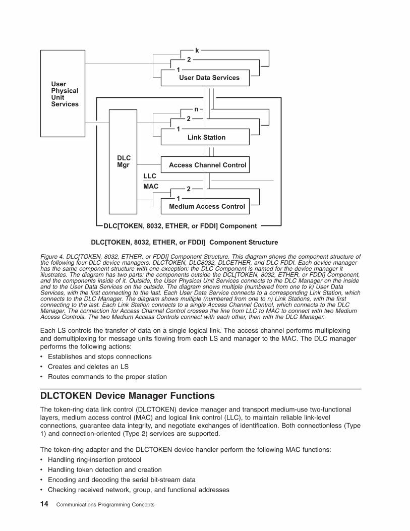
Each LS controls the transfer of data on a single logical link. The access channel performs multiplexing
and demultiplexing for message units flowing from each LS and manager to the MAC. The DLC manager
performs the following actions:
v Establishes and stops connections
v Creates and deletes an LS
v Routes commands to the proper station
DLCTOKEN Device Manager Functions
The token-ring data link control (DLCTOKEN) device manager and transport medium-use two-functional
layers, medium access control (MAC) and logical link control (LLC), to maintain reliable link-level
connections, guarantee data integrity, and negotiate exchanges of identification. Both connectionless (Type
1) and connection-oriented (Type 2) services are supported.
The token-ring adapter and the DLCTOKEN device handler perform the following MAC functions:
v Handling ring-insertion protocol
v Handling token detection and creation
v Encoding and decoding the serial bit-stream data
v Checking received network, group, and functional addresses
Link Station
Access Channel ControlDLCMgr
UserPhysicalUnitServices
LLC
MAC
1
1
Medium Access Control
2
2
n
1
2
k
DLC[TOKEN, 8032, ETHER, or FDDI] Component
User Data Services
DLC[TOKEN, 8032, ETHER, or FDDI] Component Structure
Figure 4. DLC[TOKEN, 8032, ETHER, or FDDI] Component Structure. This diagram shows the component structure of
the following four DLC device managers: DLCTOKEN, DLC8032, DLCETHER, and DLC FDDI. Each device manager
has the same component structure with one exception: the DLC Component is named for the device manager it
illustrates. The diagram has two parts: the components outside the DCL[TOKEN, 8032, ETHER, or FDDI] Component,
and the components inside of it. Outside, the User Physical Unit Services connects to the DLC Manager on the inside
and to the User Data Services on the outside. The diagram shows multiple (numbered from one to k) User Data
Services, with the first connecting to the last. Each User Data Service connects to a corresponding Link Station, which
connects to the DLC Manager. The diagram shows multiple (numbered from one to n) Link Stations, with the first
connecting to the last. Each Link Station connects to a single Access Channel Control, which connects to the DLC
Manager. The connection for Access Channel Control crosses the line from LLC to MAC to connect with two Medium
Access Controls. The two Medium Access Controls connect with each other, then with the DLC Manager.
14 Communications Programming Concepts
v Routing of received frames based on the LLC or MAC indicator and using the destination service
access point (SAP) address if an LLC frame was received
v Generating cyclic redundancy checks (CRC)
v Handling frame delimiters, such as start or end delimiters and frame status fields.
v Handling fail-safe time outs.
DLCTOKEN performs additional MAC functions, such as:
v Framing control fields on transmit frames
v Network-addressing on transmit frames
v Routing information on transmit frames.
DLCTOKEN is also responsible for all LLC functions:
v Handling remote connection services and bridge routing, using the address-resolve and name-discovery
procedures
v Sequencing of link stations on a given port
v Generating SAP addresses on transmit frames
v Generating IEEE 802.2 LLC commands and responses on transmit frames
v Recognizing and routing of received frames to the proper SAP
v Servicing IEEE 802.2 LLC commands and responses on receive frames
v Handling frame sequencing and retries
v Handling fail-safe and inactivity time outs
v Handling reliability/availability/serviceability (RAS) counters, error logs, and link traces.
DLCTOKEN Protocol Support
The token-ring data link control (DLCTOKEN) supports the logical link control (LLC) protocol and state
tables described in the Token-Ring Network Architecture Reference, which also contains the local area
network (LAN) IEEE 802.2 LCC standard. Both address-resolve services and name-discovery services are
supported for establishing remote connections. DLCTOKEN supports a direct network interface to allow a
user to transmit and receive unnumbered information packets directly through DLCTOKEN without the
data link layer performing any protocol handling.
Station Types
A combined station is supported for a balanced (peer-to-peer) configuration on a logical point-to-point
connection. That allows either station to initiate asynchronously the transmission of commands at any
response opportunity. The sender in each combined station controls the receiver in the other station. Data
transmissions then flow as primary commands, and acknowledgments and status flow as secondary
responses.
Response Modes
Both asynchronous disconnect mode (ADM) and asynchronous balanced mode extended (ABME) are
supported. ADM is entered by default whenever a link session is initiated, and is switched to ABME only
after the set asynchronous balanced mode extended (SABME) command sequence is complete. Once
operating in ABME, information frames containing user data can be transferred. ABME then remains active
until the LLC session terminates, which occurs because of a disconnect (DISC) command packet
sequence or a major link error.
Token-Ring Data Packet
All communication between a local and remote station is accomplished by the transmission of a packet
that contains token-ring headers and trailers as well as an encapsulated LLC Link Protocol Data Unit
Chapter 1. Data Link Control 15
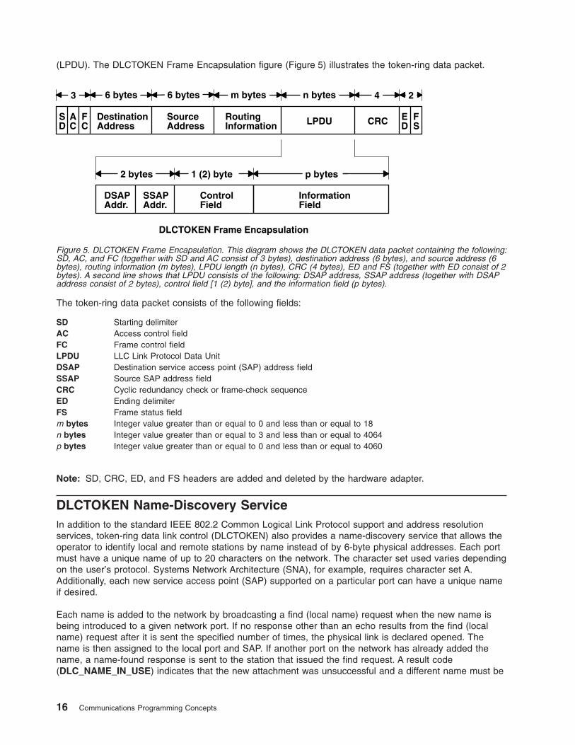
(LPDU). The DLCTOKEN Frame Encapsulation figure (Figure 5) illustrates the token-ring data packet.
The token-ring data packet consists of the following fields:
SD Starting delimiter
AC Access control field
FC Frame control field
LPDU LLC Link Protocol Data Unit
DSAP Destination service access point (SAP) address field
SSAP Source SAP address field
CRC Cyclic redundancy check or frame-check sequence
ED Ending delimiter
FS Frame status field
m bytes Integer value greater than or equal to 0 and less than or equal to 18
n bytes Integer value greater than or equal to 3 and less than or equal to 4064
p bytes Integer value greater than or equal to 0 and less than or equal to 4060
Note: SD, CRC, ED, and FS headers are added and deleted by the hardware adapter.
DLCTOKEN Name-Discovery Service
In addition to the standard IEEE 802.2 Common Logical Link Protocol support and address resolution
services, token-ring data link control (DLCTOKEN) also provides a name-discovery service that allows the
operator to identify local and remote stations by name instead of by 6-byte physical addresses. Each port
must have a unique name of up to 20 characters on the network. The character set used varies depending
on the user’s protocol. Systems Network Architecture (SNA), for example, requires character set A.
Additionally, each new service access point (SAP) supported on a particular port can have a unique name
if desired.
Each name is added to the network by broadcasting a find (local name) request when the new name is
being introduced to a given network port. If no response other than an echo results from the find (local
name) request after it is sent the specified number of times, the physical link is declared opened. The
name is then assigned to the local port and SAP. If another port on the network has already added the
name, a name-found response is sent to the station that issued the find request. A result code
(DLC_NAME_IN_USE) indicates that the new attachment was unsuccessful and a different name must be
DSAPAddr.
SSAPAddr.
ControlField
InformationField
2 bytes p bytes1 (2) byte
DestinationAddress
SourceAddress
RoutingInformation LPDU CRC
6 bytes 6 bytes m bytes
SD
AC
FC
4 2
ED
FS
n bytes3
DLCTOKEN Frame Encapsulation
Figure 5. DLCTOKEN Frame Encapsulation. This diagram shows the DLCTOKEN data packet containing the following:
SD, AC, and FC (together with SD and AC consist of 3 bytes), destination address (6 bytes), and source address (6
bytes), routing information (m bytes), LPDU length (n bytes), CRC (4 bytes), ED and FS (together with ED consist of 2
bytes). A second line shows that LPDU consists of the following: DSAP address, SSAP address (together with DSAP
address consist of 2 bytes), control field [1 (2) byte], and the information field (p bytes).
16 Communications Programming Concepts
chosen. Calls are established by broadcasting a find (remote name) request to the network and waiting for
a response from the port with the specified name. Only ports that have listen attachments pending, receive
colliding find requests, or are already attached to the requesting remote station answer a find request.
LAN Find Data Format
Find Header
0-1 Byte length of the find packet including the length field
2-3 Key 0x0001
4-n Remaining control vectors
Target Name
0-1 Vector length = 0x000F to 0x0022
2-3 Key 0x0004
4-9 Name structure architecture ID:
4-5 Subvector length = 0x0006
6-7 Key 0x4011
8-9 Identifier = 0x8000 (locally administered)
10-m Object name:
10-11 Subvector length = 0x0005 to 0x000C
12-13 Key 0x4010
14-m Target’s name (1 to 20 bytes)
Source Name
0-1 Vector length = 0x000F to 0x0022
2-3 Key 0x000D
4-9 Name structure architecture ID:
4-5 Subvector length = 0x0006
6-7 Key 0x4011
8-9 Identifier = 0x8000 (locally administered)
10-p Object name:
10-11 Subvector length = 0x0005 to 0x000C
12-13 Key 0x4010
14-p Source’s name (1 to 20 bytes)
Correlator
0-1 Vector length = 0x0008
2-3 Key 0x4003
Chapter 1. Data Link Control 17
4-7 Correlator value:
Byte 4 Bit 0
1 means this is a SAP correlator for a find (self)
Byte 4 Bit 0
0 means this is an LS correlator for a find (remote)
Source Medium Access Control (MAC) Address
0-1 Vector length = 0x000A
2-3 Key 0x4006
4-9 Source’s MAC address (6 bytes)
Source SAP
0-1 Vector length = 0x0005
2-3 Key 0x4007
4 Source’s SAP address
LAN Found Data Format
Found Header
0-1 Byte length of the found packet including the length field
2-3 Key 0x0002
4-n Remaining control vectors
Correlator
0-1 Vector length = 0x0008
2-3 Key 0x4003
4-7 Correlator value:
Byte 4 Bit 0
1 means this is a SAP correlator for a find (self).
Byte 4 Bit 0
0 means this is an LS correlator for a find (remote).
Source MAC Address
0-1 Vector length = 0x000A
2-3 Key 0x4006
4-9 Source’s MAC address (6 bytes)
Source SAP
0-1 Vector length = 0x0005
2-3 Key 0x4007
4 Source’s SAP address
18 Communications Programming Concepts
Response Code
0-1 Vector length = 0x0005
2-3 Key 0x400B
4 Response code:
B’0xxx xxxx’
Positive response
B’0000 0001’
Resources available
B’1xxx xxxx’
Negative response
B’1000 0001’
Insufficient resources
Bridge Route Discovery
DLCTOKEN caches any returned bridge-routing information from a remote station for each command or
datagram packet received and generates send-packet headers with the reverse route. This operation
allows dynamic alteration of the bridge route taken throughout the link station attachment. There is also a
provision to alter the cached routing field with the DLC_ALT_RTE ioctl operation. This ioctl operation
allows the user to dynamically change the bridge route taken by link station send packets. Once the
DLC_ALT_RTE ioctl operation is issued and accepted by the link station, dynamic caching of the received
route is stopped, and subsequent send packets carry the ioctl operation’s routing value.
Network data packets are not associated with a link station attachment, so any bridge routing field has to
come from the user sending the packet. DLCTOKEN has no involvement in the bridge routing of network
data packets.
DLCTOKEN Direct Network Services
Some users wish to handle their own unnumbered information packets on the network without the aid of
the data link layer within the token-ring data link control (DLCTOKEN). A direct network interface allows an
entire packet to be generated and sent by a user after the user service access point (SAP) has been
opened. The interface allows full control of every field in the data link header for each write call issued.
Also provided is the ability to view the entire packet contents on received frames. The criteria for a direct
network write are:
v The local SAP must be valid and opened.
v The data link control byte must indicate unnumbered information (0x03).
DLCTOKEN Connection Contention
Dual paths to the same nodes are detected by the token-ring device manager in one of two ways. First,
when a call is in progress to a remote node that is also trying to call the local node, the incoming find
(remote name) request is treated as if a local listen were outstanding. Second, when a pending local listen
is acquired by a call from a remote node and the local user issues a call to the active remote node, a
result code (DLC_REMOTE_CONN) is returned with the link station correlator of the active attachment,
allowing the user to relink attachment pointers.
Initiating DLCTOKEN Link Sessions
When a link station (LS) is opened, the token-ring data link control (DLCTOKEN) is initialized at the open
LS as a combined station in asynchronous disconnect mode (ADM). As a secondary or combined station,
DLCTOKEN is in a receive state waiting for a command frame from the primary or combined station. The
following command frames are accepted by the secondary or combined station at this time:
Chapter 1. Data Link Control 19
SABME Set asynchronous balanced mode extended
XID Exchange station identification
TEST Test link
UI Unnumbered information - datagram
DISC Disconnect
Any other command frame is ignored. Once a SABME is received, the station is ready for normal data
transfer and the following frames are also accepted:
I Information
RR Receive ready
RNR Receive not ready
REJ Reject
As a primary or combined station, DLCTOKEN can perform ADM XID, ADM TEST exchanges, send
datagrams, or connect the remote to the asynchronous balanced mode extended (ABME). XID exchanges
allow the primary or combined station to send out its station-specific identification to the secondary or
combined station and obtain a response. Once an XID response is received, any attached information field
is passed to the user for further action.
TEST exchanges allow the primary or combined station to send out a buffer of information that will be
echoed by the secondary or combined station in order to test the integrity of the link.
Initiation of the normal data exchange mode, ABME, causes the primary or combined station to send an
SABME to the secondary or combined station. Once sent successfully, the connection is said to be
contacted and the user is notified. Information frames can now be sent and received between the linked
stations.
Stopping DLCTOKEN Link Sessions
The user or the remote station can be stopped by the token-ring data link control (DLCTOKEN):
v Issue a DLC_HALT_LS command. This command will cause the primary or combined station to initiate
a disconnect (DISC) packet sequence.
v Sending a DISC command packet as a primary or combined station.
v Receiving an inactivity timeout can stop a DLCTOKEN link session. This action is useful in detecting a
loss of connection in the middle of a session.
Note: Abnormal stopping is caused by certain protocol violations or by resource outages.
DLCTOKEN Programming Interfaces
The token-ring data link control (DLCTOKEN) conforms to the generic data link control (GDLC) guidelines
except where noted below. Additional structures and definitions for DLCTOKEN can be found in the
/usr/include/sys/trlextcb.h file.
Note: The dlc prefix is replaced with the trl prefix for DLCTOKEN.
trlclose DLCTOKEN is fully compatible with the dlcclose GDLC interface.
trlconfig DLCTOKEN is fully compatible with the dlcconfig GDLC interface. No initialization parameters are
required.
trlmpx DLCTOKEN is fully compatible with the dlcmpx GDLC interface.
trlopen DLCTOKEN is fully compatible with the dlcopen GDLC interface.
20 Communications Programming Concepts
trlread DLCTOKEN is compatible with the dlcread GDLC interface with the following conditions:
v The readx subroutines can have DLCTOKEN data link header information prefixed to the I-field
being passed to the application. This is optional based on the readx subroutine data link header
length extension parameter in the gdl_io_ext structure.
v If this field is nonzero, DLCTOKEN copies the data link header and the I-field to user space and
sets the actual length of the data link header into the length field.
v If the field is 0, no data link header information is copied to user space. See the DLCTOKEN
Frame Encapsulation figure (Figure 5 on page 16) for more details.
The following kernel receive packet function handlers always have the DLCTOKEN data link header
information within the communications memory buffer (mbuf) and can locate it by subtracting the length
passed (in the gdl_io_ext structure) from the data offset field of the mbuf structure.
trlselect DLCTOKEN is fully compatible with the dlcselect GDLC interface.
trlwrite DLCTOKEN is compatible with the dlcwrite GDLC interface, with the exception that network data
can only be written as an unnumbered information (UI) packet and must have the complete data
link header prefixed to the data. DLCTOKEN verifies that the local (source) service access point
(SAP) is enabled and that the control byte is UI (0x03). See the DLCTOKEN Frame Encapsulation
figure (Figure 5 on page 16) for more details.
trlioctl DLCTOKEN is compatible with the dlcioctl GDLC interface, with conditions on the following
operations:
v DLC_ENABLE_SAP
v DLC_START_LS
v DLC_ALTER
v DLC_QUERY_SAP
v DLC_QUERY_LS
v DLC_ENTER_SHOLD
v DLC_EXIT_SHOLD
v DLC_ADD_GROUP
v DLC_ADD_FUNC_ADDR
v DLC_DEL_FUNC_ADDR
v DLC_DEL GRP
v IOCINFO
The following sections describe these conditions in detail.
DLC_ENABLE_SAP
The ioctl subroutine argument structure for enabling a SAP (dlc_esap_arg) has the following specifics:
v The grp_addr (group address) field for the token ring contains the four least significant bytes of the
desired six-byte group address. Only bits 1 through 31 are valid. Bit 0 is ignored. The most significant
two bytes are automatically compared for 0xC000 by the adapter.
v The func_addr_mask (functional address mask) field must be the logical OR operation with the
functional address on the adapter, which allows packets that are destined for specified functions to be
received by the local adapter. Only bits 1 through 29 are valid. Bits 0, 30, and 31 are ignored. The most
significant two bytes of the full six-byte functional address are automatically compared for 0xC000 by
the adapter.
The following is an example of a Network Basic Input/Output System (NetBIOS) functional address:
To select the NETBIOS functional address of 0xC000_0000_0080,
the functional address mask is set to 0x0000_0080.
Note: DLCTOKEN does not check to determine whether a received packet was accepted by the
adapter due to a preset network address, group address, or functional address.
Chapter 1. Data Link Control 21
v The max_ls (maximum link stations) field cannot exceed a value of 255.
v The following common SAP flags are not supported:
ENCD Specifies a synchronous data link control (SDLC) serial encoding.
NTWK Indicates a teleprocessing network type.
LINK Indicates a teleprocessing link type.
PHYC Indicates a physical network call (teleprocessing).
ANSW Indicates a teleprocessing autocall and autoanswer.
v Group SAPs are not supported, so the num_grp_saps (number of group SAPs) field must be set to 0.
v The laddr_name (local address and name) field and its associated length are only used for name
discovery when the common SAP flag ADDR is set to 0. When resolve procedures are used (that is,
the ADDR flag is set to 1), DLCTOKEN obtains the local network address from the device handler and
not from the dlc_esap_arg structure.
v The local_sap (local service access point) field can be set to any value except null SAP (0x00) or
discovery SAP (0xFC). Also, the low-order bit must be set to 0 (B`nnnnnnn0’) to indicate an individual
address.
v No protocol-specific data area is required for DLCTOKEN to enable a SAP.
DLC_START_LS
The ioctl subroutine argument structure for starting a link station (dlc_sls_arg) has the following specifics:
v The following common link station (LS) flags are not supported:
STAT Specifies a station type for SDLC.
NEGO Specifies a negotiable station type for SDLC.
v The raddr_name (remote address and name) field is only used for outgoing calls when the
DLC_SLS_LSVC common LS flag is active.
v The maxif (maximum I-field length) field can be set to any value greater than 0. See the DLCTOKEN
Frame Encapsulation figure (Figure 5 on page 16) for more details. DLCTOKEN adjusts this value to a
maximum of 4060 bytes if set too large.
v The rcv_wind (receive window) field can be set to any value between 1 and 127 inclusive. The
recommended value is 127.
v The xmit_wind (transmit window) field can be set to any value between 1 and 127 inclusive. The
recommended value is 26.
v The rsap (remote SAP) field can be set to any value except null SAP (0x00) or name-discovery SAP
(0xFC). Also, the low-order bit must be set to 0 (B`nnnnnnn0’) to indicate an individual address.
v The max_repoll field can be set to any value from 1 to 255. The recommended value is 8.
v The repoll_time field is defined in increments of 0.5 seconds and can be set to any value from 1 to 255,
inclusive. The recommended value is 2, giving a time-out duration of 1 to 1.5 seconds.
v The ack_time (acknowledgment time) field is defined in increments of 0.5 seconds, and can be set to
any value between 1 and 255, inclusive. The recommended value is 1, giving a time-out duration of 0.5
to 1 second.
v The inact_time (inactivity time) field is defined in increments of 1 second and can be set to any value
between 1 and 255 inclusive. The recommended value is 48, giving a time-out duration of 48 to 48.5
seconds.
v The force_time (force halt time) field is defined in increments of 1 second and can be set to any value
between 1 and 16383, inclusive. The recommended value is 120, giving a time-out duration of
approximately 2 minutes.
v A protocol-specific data area must be appended to the generic start link station argument (dlc_sls_arg).
This structure provides DLCTOKEN with additional protocol-specific configuration parameters:
22 Communications Programming Concepts
struct trl_start_psd
{
uchar_t pkt_prty; /* ring access packet priority */
uchar_t dyna_wnd; /* dynamic window increment */
ushort_t reserved; /* currently not used */
};
The protocol-specific parameters are as follows:
pkt_prty Specifies the ring access priority that the user wishes to reserve on transmit packets. Values of 0 to 3
are supported, where 0 is the lowest priority and 3 is the highest priority.
dyna_wnd Specifies the number of consecutive sequenced packets that must be acknowledged by the remote
station before the local transmit window count can be incremented. Network congestion causes the
local transmit window count to drop automatically to a value of 1. The dynamic window increment
allows a gradual increase in network traffic after a period of congestion. This field can be set to any
value between 1 and 255, inclusive. The recommended value is 1.
DLC_ALTER
The ioctl subroutine argument structure for altering an LS (dlc_alter_arg) has the following specifics:
v The following alter flags are not supported:
SM1, SM2 Sets SDLC control mode.
v A protocol-specific data area must be appended to the generic alter link station argument structure
(dlc_alter_arg). This structure provides DLCTOKEN with additional protocol-specific alter parameters.
#define TRL_ALTER_PRTY 0x80000000 /* alter packet priority */
#define TRL_ALTER_DYNA 0x40000000 /* alter dynamic window incr.*/
struct trl_start_psd
{
ulong_t flags; /* specific alter flags */
uchar_t pkt_prty; /* ring access packet priority value */
uchar_t dyna_wnd; /* dynamic window increment value */
ushort_t reserved; /* currently not used */
};
#define TRL_ALTER_PRTY 0x80000000 /* alter packet priority */
#define TRL_ALTER_DYNA 0x40000000 /* alter dynamic window incr.*/
struct trl_start_psd
{
__ulong32_t flags; /* specific alter flags */
uchar_t pkt_prty; /* ring access packet priority value */
uchar_t dyna_wnd; /* dynamic window increment value */
ushort_t reserved; /* currently not used */
};
Specific alter flags are as follows:
TRL_ALTER_PRTY Specifies alter priority. If this flag is set to 1, the pkt_prty value field replaces the current
priority value being used by the LS. The LS must be started for this alter command to be
valid.
TRL_ALTER_DYNA Specifies alter dynamic window. If this flag is set to 1, the dyna_wnd value field replaces
the current dynamic window value being used by the LS. The LS must be started for this
alter command to be valid.
The protocol-specific parameters are as follows:
pkt_prty Specifies the new priority reservation value for transmit packets.
dyna_wnd Specifies the new dynamic window value to control network congestion.
Chapter 1. Data Link Control 23
DLC_QUERY_SAP
The device driver-dependent data returned from DLCTOKEN for this ioctl operation is the
tok_ndd_stats_t structure defined in the /usr/include/sys/cdli_tokuser.h file.
DLC_QUERY_LS
There is no protocol-specific data area supported by DLCTOKEN for this ioctl operation.
DLC_ENTER_SHOLD
The enter_short_hold option is not supported by DLCTOKEN.
DLC_EXIT_SHOLD
The exit_short_hold option is not supported by DLCTOKEN.
DLC_ADD_GROUP
The add_group, or multicast address, option is supported by the DLCTOKEN device manager. This ioctl
operation is a four-byte value as described in the DLC_ENABLE_SAP ioctl operation definition.
DLC_ADD_FUNC_ADDR
The len_func_addr_mask (functional address mask length) field must be set to 4, and the func_addr_mask
(functional address mask) field must be the logical OR operation with the functional address on the
adapter. Only bits 1 through 29 are valid. Bits 0, 30, and 31 are ignored. The most significant two bytes of
the full six-byte functional address are automatically compared for 0xC000 by the adapter and cannot be
added.
DLC_DEL_FUNC_ADDR
The len_func_addr_mask (functional address mask length) field must be set to 4, and the func_addr_mask
(functional address mask) field must have each bit that you wish to reset set to 1 within the functional
address on the adapter. Only bits 1 through 29 are valid. Bits 0, 30, and 31 are ignored. The most
significant two bytes of the full six-byte functional address are automatically compared for 0xC000 by the
adapter and cannot be deleted.
DLC_DEL_GRP
The delete group or multicast option is supported by the DLCTOKEN device manager. The address being
removed must match an address that was added with a DLC_ENABLE_SAP or DLC_ADD_GRP ioctl
operation.
IOCINFO
The ioctype variable returned is defined as a DD_DLC definition, and the subtype returned is
DS_DLCTOKEN.
IEEE 802.3 Ethernet Data Link Control Overview
IEEE 802.3 Ethernet data link control (DLC8023) is a device manager that follows the generic data link
control (GDLC) interface definition. This DLC device manager provides a passthrough capability that
allows transparent data flow and provides an access procedure to transfer four types of data over an
Ethernet local area network (LAN):
v Datagrams
v Sequenced data
v Identification data
v Logical link controls.
24 Communications Programming Concepts
The Ethernet device handler and the Ethernet high performance LAN adapter transfer data.
For more information about DLC8023, see:
v “DLC8023 Device Manager Nodes”
v “DLC8023 Device Manager Functions”
v “DLC8023 Protocol Support” on page 26
v “DLC8023 Name-Discovery Services” on page 27
v “DLC8023 Direct Network Services” on page 30
v “DLC8023 Connection Contention” on page 30
v “DLC8023 Link Sessions” on page 30
v “DLC8023 Programming Interfaces” on page 31
DLC8023 Device Manager Nodes
The DLC8023 device manager on an Ethernet local area network (LAN) operates between two or more
nodes using medium access control (MAC) procedures and IEEE 802.2 logical link control (LLC)
procedures. MAC and LLC procedures are defined in the IEEE Project 802 Local Area Network Standards.
Specific state tables used are found in the Token-Ring Network Architecture Reference. The DLC8023
device manager supports:
v Asynchronous disconnected mode (ADM) and asynchronous balanced mode extended (ABME)
v Two-way, simultaneous (full-duplex) data flow
v Multiple point-to-point logical attachments on the LAN, using the network address and service access
point (SAP) address
v Peer-to-peer relationship with remote stations
v Both name-discovery and address-resolve services.
The DLC8023 device manager provides full-duplex, peer-data transfer capabilities over an Ethernet LAN.
The Ethernet LAN must use the IEEE 802.3 carrier sense multiple access with collision detection
(CSMA/CD) medium access control protocol and a superset of the IEEE 802.2 LLC protocol.
Note: Multiple adapters are supported with a maximum of 255 logical attachments per adapter.
LLC refers to the DLC manager, access-channel, and link station (LS) subcomponents of a GDLC
component, such as the DLC8023 device manager, as illustrated in the DLC[TOKEN, 8032, ETHER, or
FDDI] Component Structure figure (Figure 4 on page 14).
Each LS controls the transfer of data on a single logical link. The access channel performs multiplexing
and demultiplexing for message units flowing from the link stations and DLC manager to MAC. The DLC
manager performs the following actions:
v Establishes and terminates connections
v Creates and deletes LSs
v Routes commands to the proper station.
DLC8023 Device Manager Functions
The IEEE 802.3 Ethernet data link control (DLC8023) device manager and transport medium use two
functional layers, medium access control (MAC) and logical link control (LLC), to maintain reliable link-level
connections, guarantee data integrity, and negotiate exchanges of identification. Both connectionless (Type
1) and connection-oriented (Type 2) services are supported.
The Ethernet adapter and DLC8023 device handler can perform the following MAC functions:
v Managing the carrier-sense multiple access with collision detection (CSMA/CD) LLC algorithm
Chapter 1. Data Link Control 25
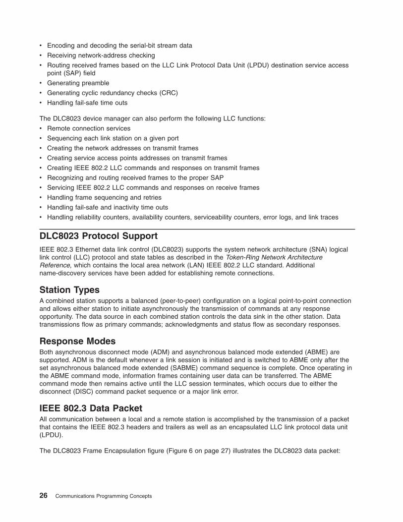
v Encoding and decoding the serial-bit stream data
v Receiving network-address checking
v Routing received frames based on the LLC Link Protocol Data Unit (LPDU) destination service access
point (SAP) field
v Generating preamble
v Generating cyclic redundancy checks (CRC)
v Handling fail-safe time outs
The DLC8023 device manager can also perform the following LLC functions:
v Remote connection services
v Sequencing each link station on a given port
v Creating the network addresses on transmit frames
v Creating service access points addresses on transmit frames
v Creating IEEE 802.2 LLC commands and responses on transmit frames
v Recognizing and routing received frames to the proper SAP
v Servicing IEEE 802.2 LLC commands and responses on receive frames
v Handling frame sequencing and retries
v Handling fail-safe and inactivity time outs
v Handling reliability counters, availability counters, serviceability counters, error logs, and link traces
DLC8023 Protocol Support
IEEE 802.3 Ethernet data link control (DLC8023) supports the system network architecture (SNA) logical
link control (LLC) protocol and state tables as described in the Token-Ring Network Architecture
Reference, which contains the local area network (LAN) IEEE 802.2 LLC standard. Additional
name-discovery services have been added for establishing remote connections.
Station Types
A combined station supports a balanced (peer-to-peer) configuration on a logical point-to-point connection
and allows either station to initiate asynchronously the transmission of commands at any response
opportunity. The data source in each combined station controls the data sink in the other station. Data
transmissions flow as primary commands; acknowledgments and status flow as secondary responses.
Response Modes
Both asynchronous disconnect mode (ADM) and asynchronous balanced mode extended (ABME) are
supported. ADM is the default whenever a link session is initiated and is switched to ABME only after the
set asynchronous balanced mode extended (SABME) command sequence is complete. Once operating in
the ABME command mode, information frames containing user data can be transferred. The ABME
command mode then remains active until the LLC session terminates, which occurs due to either the
disconnect (DISC) command packet sequence or a major link error.
IEEE 802.3 Data Packet
All communication between a local and a remote station is accomplished by the transmission of a packet
that contains the IEEE 802.3 headers and trailers as well as an encapsulated LLC link protocol data unit
(LPDU).
The DLC8023 Frame Encapsulation figure (Figure 6 on page 27) illustrates the DLC8023 data packet:
26 Communications Programming Concepts
The IEEE 802.3 data packet consists of the following fields:
LPDU LLC Link Protocol Data Unit
DSAP Destination Service Access Point (SAP) address field
SSAP Source SAP Address Field
CRC Cyclic Redundancy Check or frame1-check sequence
m bytes Integer value greater than or equal to 46 and less than or equal to 1500
p bytes Integer value greater than or equal to 0 and less than or equal to 1496
Note: Preamble and CRC are added and deleted by the hardware adapter.
DLC8023 Name-Discovery Services
In addition to the standard IEEE 802.2 common logical link protocol (CLLP) support and the address
resolution services, IEEE 802.3 Ethernet data link control (DLC8023) also provides a name-discovery
service that allows the operator to identify local and remote stations by name instead of by six-byte
physical addresses. Each port must have a unique name of up to 20 characters on the network. The
character set used depends on the user’s protocol. For example, systems network architecture (SNA)
requires character set A. Each new service access point (SAP) supported on a particular port may have a
unique name, if desired.
Each name is added to the network by broadcasting a find (local name) request. After the find (local
name) request is sent the required number of times, if no response is returned, the physical link is
declared opened. The name is then assigned to the local port and SAP. If another port on the network has
already added the name, a name-found response is sent to the station that issued the find request, and
the new attachment fails with a result code (DLC_NAME_IN_USE). This code indicates that a different
name must be selected. Calls are established by broadcasting a find (remote name) request to the
network and waiting for a response from the port with the specified name. Ports with attachments pending,
colliding find requests, or an attachment to the requesting remote station will answer a find request.
LAN Find Data Format
Find Header
0-1 Byte length of the find packet including the length field
2-3 Key 0x0001
DSAPAddr.
SSAPAddr.
ControlField
InformationField
2 bytes p bytes1 (2) byte
LPDULength
DestinationAddress
SourceAddressPreamble Pad CRC
8 bytes 6 bytes 6 bytes m bytes
LPDU
2 4
DLC8023 Frame Encapsulation
Figure 6. DLC8023 Frame Encapsulation. This diagram shows the DLC8023 data packet containing the following:
preamble (8 bytes), destination address (6 bytes), source address (6 bytes), LPDU length (2 bytes), LPDU, Pad
(together with LPDU consist of m bytes), and CRC (4 bytes). A second line shows that LPDU consists of the following:
DSAP address, SSAP address (together with DSAP address consist of 2 bytes), control field [1 (2) byte], and the
information field (p bytes).
Chapter 1. Data Link Control 27
4-n Remaining control vectors
Target Name
0-1 Vector length = 0x000F to 0x0022
2-3 Key 0x0004
4-9 Name structure architecture ID:
4-5 Subvector length = 0x0006
6-7 Key 0x4011
8-9 Identifier = 0x8000 (locally administered)
10-m Object name:
10-11 Subvector length = 0x0005 to 0x000C
12-13 Key 0x4010
14-m Target name (1 to 20 bytes)
Source Name
0-1 Vector length = 0x000F to 0x0022
2-3 Key 0x000D
4-9 Name structure architecture ID:
4-5 Subvector length = 0x0006
6-7 Key 0x4011
8-9 Identifier = 0x8000 (locally administered)
10-p Object name:
10-11 Subvector length = 0x0005 to 0x000C
12-13 Key 0x4010
14-p Source name (1 to 20 bytes)
Correlator
0-1 Vector length = 0x0008
2-3 Key 0x4003
4-7 Correlator value:
Byte 4 Bit 0
1 represents a SAP correlator for a find (self)
Byte 4 Bit 0
0 represents a link station (LS) correlator for a find (remote)
Source Medium Access Control (MAC) Address
0-1 Vector length = 0x000A
2-3 Key 0x4006
4-9 Source MAC address (6 bytes)
28 Communications Programming Concepts
Source SAP
0-1 Vector length = 0x0005
2-3 Key 0x4007
4 Source SAP address
LAN Found Data Format
Found Header
0-1 Byte length of the found packet including the length field
2-3 Key 0x0002
4-n Remaining control vectors
Correlator
0-1 Vector length = 0x0008
2-3 Key 0x4003
4-7 Correlator value:
Byte 4 Bit 0
1 represents a SAP correlator for a find (self)
Byte 4 Bit 0
0 represents an LS correlator for a find (remote)
Source MAC Address
0-1 Vector length = 0x000A
2-3 Key 0x4006
4-9 Source MAC address (6 bytes)
Source SAP
0-1 Vector length = 0x0005
2-3 Key 0x4007
4 Source SAP address
Response Code
0-1 Vector length = 0x0005
2-3 Key 0x400B
4 Response code:
B’0xxx xxxx’
Positive response
B’0000 0001’
Resources available
B’1xxx xxxx’
Negative response
B’1000 0001’
Insufficient resources
Chapter 1. Data Link Control 29
DLC8023 Direct Network Services
Some users wish to handle their own unnumbered information packets on the network without the aid of
the data link layer within IEEE 802.3 Ethernet data link control (DLC8023). Once a service access point
(SAP) is opened, a direct network interface allows an entire packet to be generated and sent. This action
allows full control of every field in the data link header for each write issued. Also provided is the ability to
view the entire packet contents on received frames. The criteria for a direct network write are:
v The local SAP must be valid and open.
v The data link control byte must indicate unnumbered information (0x03).
DLC8023 Connection Contention
Dual paths to the same nodes are detected by the IEEE 802.3 Etheret data link control (DLC8023) device
manager in one of two ways. First, when a call in progress to a remote node also tries to call the local
node, the incoming find (remote name) request is treated as if a local listen were outstanding. Second,
when a pending local listen is acquired by a call from a remote node and the local user issues a call to the
active remote node, a result code (DLC_REMOTE_CONN) is returned with the link station correlator of the
active attachment, allowing the user to relink attachment pointers.
DLC8023 Link Sessions
The IEEE 802.3 Etheret data link control (DLC8023) device manager is initialized at an open link station
(LS) as a combined station in asynchronous disconnect mode (ADM). As a secondary or combined station,
DLC8023 is in a receive state, waiting for a command frame from the primary or combined station.
Command frames accepted by the secondary or combined station at this time are:
SABME Set asynchronous balanced mode extended.
XID Exchange station identifications.
TEST Test links.
UI Unnumbered information - datagram.
DISC Disconnect.
Any other command frame is ignored. Once a SABME command is received, the station is ready for
normal data transfer, and the following frames are also accepted:
I Provides information.
RR Indicates a receive ready.
RNR Indicates a receive not ready.
REJ Indicates a reject.
As a primary or combined station, the DLC8023 device manager can perform ADM XID or ADM TEST
exchanges, send datagrams, or connect the remote to asynchronous balanced mode extended (ABME).
XID exchanges allow the primary or combined station to send out its station-specific identification to the
secondary or combined station and accept a response. Once an XID response is received, attached
information fields are then sent to the user for further action.
TEST exchanges allow the primary or combined station to send out a buffer of information to be echoed
by the secondary or combined station. This transfer of information tests the integrity of the link.
Initiation of the normal data exchange mode, ABME, prompts the primary or combined station to send a
SABME command to the secondary or combined station. Upon successful delivery, the connection is said
to be contacted; the user is notified. Information frames can now be sent and received between the linked
stations.
30 Communications Programming Concepts
Link Session Termination
The IEEE 802.3 Etheret data link control (DLC8023) device manager is stopped by the user or by the
remote station in the following ways:
v The user issues a close link station command to the DLC8023 device manager. The command
initiates a disconnect (DISC) packet sequence to the primary or combined station.
v The user directs the link to stop automatically after a specified period of inactivity. This is useful in
detecting a loss of connection in the middle of a session.
v The remote station terminates the link by sending a DISC command packet as a primary combined
station.
Note: Abnormal termination is a result of certain protocol violations or resource outages.
DLC8023 Programming Interfaces
The IEEE 802.3 Ethernet data link control (DLC8023) device manager conforms to generic data link
control (GDLC) guidelines, except as follows:
Note: The dlc prefix is replaced with the e3l prefix for the DLC8023 device manager.
e3lclose DLC8023 is fully compatible with the dlcclose GDLC interface.
e3lconfig DLC8023 is fully compatible with the dlcconfig GDLC interface. No initialization parameters are
required.
e3lmpx DLC8023 is fully compatible with the dlcmpx GDLC interface.
e3lopen DLC8023 is fully compatible with the dlcopen GDLC interface.
e3lread DLC8023 is compatible with the dlcread GDLC interface, under the following conditions:
v The readx subroutines can have DLC8023 data link header information prefixed to the I-field.
The data can be passed to the application in the user-defined readx subroutine data link header
length extension parameter in the gdl_io_ext structure.
v If this field has a nonzero value, DLC8023 copies the data link header and the I-field to user
space and sets the actual length of the data link header in the length field.
v If the field has a value of 0, no data link header information is copied. See the DLC8023 Frame
Encapsulation figure (Figure 6 on page 27) for more details.
The following kernel receive packet function handlers always have the DLC8023 data link header
information in the communications memory buffer (mbuf), and can locate this information by subtracting
the length passed in the gdl_io_ext structure from the data offset field.
e3lselect DLC8023 is fully compatible with the dlcselect GDLC interface.
e3lwrite DLC8023 is compatible with the dlcwrite GDLC interface. The exceptions are that network data
can only be written as an unnumbered information (UI) packet and must have the complete data
link header prefixed. DLC8023 verifies that the local, or source, service access point (SAP) is
enabled and that the control byte is UI (0x03). See the DLC8023 Frame Encapsulation figure
(Figure 6 on page 27) for more details.
Chapter 1. Data Link Control 31
e3lioctl DLC8023 is compatible with the dlcioctl GDLC interface, with conditions on the following
operations:
v DLC_ENABLE_SAP
v DLC_START_LS
v DLC_ALTER
v DLC_QUERY_SAP
v DLC_QUERY_LS
v DLC_ENTER_SHOLD
v DLC_EXIT_SHOLD
v DLC_ADD_GROUP
v DLC_ADD_FUNC_ADDR
v DLC_DEL_FUNC_ADDR
v DLC_DEL_GRP
v IOCINFO
The following sections describe these conditions.
DLC_ENABLE_SAP
The ioctl subroutine argument structure to enable a SAP (dlc_esap_arg) has the following specifics:
v The grp_addr field is a 6-byte value as specified in the draft IEEE Standard 802.3 specifications. Octet
grp_addr[0] specifies the most significant byte and octet grp_addr[5] specifies the least significant byte.
Each octet of the address field is transmitted, least significant bit first. Group addresses sometimes are
called multicast addresses.
An example of a group address follows:
0x0900_2B00_0004
Note: The DLC8023 device manager does not check whether a received packet was accepted by the
adapter due to a preset network address or group address.
v The max_ls (maximum link station) field cannot exceed a value of 255.
v The following common SAP flags are not supported:
ENCD Indicates synchronous data link control (SDLC) serial encoding.
NTWK Indicates a teleprocessing network type.
LINK Indicates teleprocessing link type.
PHYC Indicates a physical network call (teleprocessing).
ANSW Indicates a teleprocessing autocall and autoanswer.
v Group SAPs are not supported. Therefore the num_grp_saps (number of group SAPs) field must be set
to 0.
v The laddr_name (local address name) field and its associated length are used for name-discovery when
the common SAP flag ADDR is set to 0. When resolve procedures are used (that is, the ADDR flag is
set to 1), the DLC8023 device manager obtains the local network address from the device handler and
not from the dlc_esap_arg structure.
v The local_sap (local service access point) field can be set to any value except null SAP (0x00) or the
name-discovery SAP (0xFC). Also, the low-order bit must be set to 0 (B`nnnnnnn0’) to indicate an
individual address.
v No protocol-specific data area is required for the DLC8023 device manager to enable a SAP.
DLC_START_LS
The ioctl subroutine argument structure specifics to start a link station (dlc_sls_arg) are as follows:
32 Communications Programming Concepts
v These common link station flags are not supported:
STAT Indicates a station type for an SDLC.
NEGO Indicates a negotiable station type for an SDLC.
v The raddr_name (remote address and name) field is used for outgoing calls when the DLC_SLS_LSVC
common link station flag is active.
v The maxif (maximum information field length) field can be set to any value greater than 0. See the
DLC8023 Frame Encapsulation figure (Figure 6 on page 27) for the supported byte lengths. If a byte is
set too large, DLC8023 adjusts it to a maximum of 1496 bytes.
v The rcv_wind (receive window) field can be set to any value between 1 and 127 inclusive. The
recommended value is 127.
v The xmit_wind (transmit window) field can be set to any value between 1 and 127 inclusive. The
recommended value is 26.
v The rsap (remote SAP) field can be set to any value except null SAP (0x00) or the name-discovery SAP
(0xFC). The low-order bit must be set to 0 (B`nnnnnnn0’) to indicate an individual address.
v The max_repoll field can be set to any value between 1 and 255 inclusive. The recommended value is
8.
v The repoll_time field is defined in increments of 0.5 seconds and can be set to any value between 1
and 255, inclusive. The recommended value is 2, giving a time-out duration of 1 to 1.5 seconds.
v The ack_time (acknowledgment time) field is defined in increments of 0.5 seconds and can be set to
any value between 1 and 255, inclusive. The recommended value is 1, giving a time-out duration of 0.5
to 1 second.
v The inact_time (inactivity time) field is defined in increments of 1 second and can be set to any value
between 1 and 255, inclusive. The recommended value is 48, giving a time-out duration of 48 to 48.5
seconds.
v The force_time (force halt time) field is defined in increments of 1 second and can be set to any value
between 1 and 16383, inclusive. The recommended value is 120, giving a time-out duration of
approximately 2 minutes.
v No protocol-specific data area is required for the DLC8023 device manager to start a link station.
DLC_ALTER
The ioctl subroutine argument structure for altering a link station (dlc_alter_arg) has the following
specifics:
v These alter flags are not supported:
RTE Alter routing.
SM1, SM2 Set SDLC control mode.
v A protocol-specific data area is not required for DLC8023 to alter a link station.
DLC_QUERY_SAP
The device driver-dependent data returned from DLC8023 for this ioctl operation is the ent_ndd_stats_t
structure defined in the /usr/include/sys/cdli_entuser.h file.
DLC_QUERY_LS
No protocol-specific data area is supported by DLC8023 for this ioctl operation.
DLC_ENTER_SHOLD
The enter_short_hold option is not supported by the DLC8023 device manager.
Chapter 1. Data Link Control 33
DLC_EXIT_SHOLD
The exit_short_hold option is not supported by the DLC8023 device manager.
DLC_ADD_GROUP
The add_group, or multicast address, option is supported by the DLC8023 device manager. It is a
six-byte value as described previously in the DLC_ENABLE_SAP (group address) ioctl operation.
DLC_ADD_FUNC_ADDR
The add_functional_address option is not supported by DLC8023.
DLC_DEL_FUNC_ADDR
The delete_functional_address option is not supported by DLC8023.
DLC_DEL_GRP
The delete group or multicast option is supported by the DLC8023 device manager. The address being
removed must match an address that was added with a DLC_ENABLE_SAP or DLC_ADD_GRP ioctl
operation.
IOCINFO
The returned ioctype variable is defined as a DD_DLC definition, and the subtype returned is
DS_DLC8023.
Standard Ethernet Data Link Control Overview
Standard Ethernet data link control (DLCETHER) is a device manager that follows the generic data link
control (GDLC) interface definition. This DLC device manager provides a passthrough capability that
allows transparent data flow and provides an access procedure to transfer four types of data over a
Standard Ethernet:
v Datagrams
v Sequenced data
v Identification data
v Logical link controls
The Ethernet device handler and Ethernet high performance LAN adapter transfer the data.
For more information about DLCETHER see the following:
v “DLCETHER Device Manager Nodes” on page 35
v “DLCETHER Device Manager Functions” on page 35
v “DLCETHER Protocol Support” on page 36
v “DLCETHER Name-Discovery Services” on page 37
v “DLCETHER Direct Network Services” on page 40
v “DLCETHER Connection Contention” on page 40
v “DLCETHER Link Session Initiation” on page 40
v “DLCETHER Link Session Termination” on page 41
v “DLCETHER Programming Interfaces” on page 41
34 Communications Programming Concepts
DLCETHER Device Manager Nodes
The Standard Ethernet data link control (DLCETHER) device manager on an Ethernet local area network
(LAN) operates between two or more nodes using medium access control (MAC) procedures and IEEE
802.2 logical link control (LLC) procedures, as defined in IEEE Project 802 Local Area Network Standards.
The specific state tables implemented can be found in the Token-Ring Network Architecture Reference.
The DLCETHER device manager supports:
v Asynchronous disconnected mode (ADM) and asynchronous balanced mode extended (ABME)
v Two-way simultaneous (full-duplex) data flow
v Multiple point-to-point logical attachments on the LAN using network and service access point (SAP)
addresses
v Peer-to-peer relationship with remote station
v Both name-discovery and address-resolve services.
The Ethernet data link control provides full-duplex, peer data-transfer capabilities over an Ethernet Version
2 local area network, using the Ethernet Version 2 MAC protocol and a superset of the IEEE 802.2 LLC.
Note: Multiple adapters are supported with a maximum of 255 logical attachments per adapter.
LLC refers to the collection of manager, access channel, and link station subcomponents of a GDLC
component such as DLCETHER device manager, as illustrated in the DLC[TOKEN, 8032, ETHER, or
FDDI] Component Structure figure (Figure 4 on page 14).
Each link station (LS) controls the transfer of data on a single logical link. The access channel performs
multiplexing and demultiplexing for message units flowing from the link stations and manager to the MAC.
The DLC manager performs these actions:
v Establishes and terminates connections
v Creates and deletes link stations
v Routes commands to the proper station.
DLCETHER Device Manager Functions
The Standard Ethernet data link control (DLCETHER) device manager and transport medium use two
functional layers, medium access control (MAC) and logical link control (LLC) to maintain reliable link-level
connections, guarantee data integrity, and negotiate exchanges of identification. Both connectionless (Type
1) and connection-oriented (Type 2) services are supported.
The Ethernet adapter and the DLCETHER device handler perform the following MAC functions:
v Managing the carrier sense multiple access with collision detection (CSMA/CD) algorithm
v Encoding and decoding the serial bit stream data
v Receiving network address checking
v Routing received frames based on the LLC type field
v Generating cyclic redundancy check (CRC)
v Handling fail-safe time outs.
The DLCETHER device manager also performs the following LLC functions:
v Remote connection services
v Sequencing each link station (LS) on a given port
v Creating network addresses on transmit frames
v Creating service access point (SAP) addresses on transmit frames
v Creating IEEE 802.2 LLC commands and responses on transmit frames
Chapter 1. Data Link Control 35
v Recognizing and routing received frames to the proper SAP
v Servicing IEEE 802.2 LLC commands and responses on receive frames
v Sequencing frames and retries
v Handling fail-safe and inactivity time outs
v Handling reliability counters, availability counters, serviceability counters, error logs, and link traces.
DLCETHER Protocol Support
The Standard Ethernet data link control (DLCETHER) supports the systems network architecture (SNA)
logical link control (LLC) protocol and state tables as described in the Token-Ring Network Architecture
Reference, which also contains the local area network (LAN) IEEE 802.2 LLC standard. Additional
direct-name services have been added for establishing remote connections.
Station Type
A combined station is supported for a balanced (peer-to-peer) configuration on a logical point-to-point
connection. Either station can asynchronously initiate the transmission of commands at any response
opportunity. The data source in each combined station controls the data sink in the other station. Data
transmissions then flow as primary commands, and acknowledgments and status flow as secondary
responses.
Response Modes
Both asynchronous disconnect mode (ADM) and asynchronous balanced mode extended (ABME) are
supported. ADM is entered by default whenever a link session is initiated, and is switched to ABME only
after the set asynchronous balanced mode extended (SABME) command sequence is complete. Once
operating in ABME, information frames containing user data can be transferred. ABME then remains active
until the LLC session ends, which occurs because of a disconnect (DISC) command sequence or a major
link error.
Ethernet Data Packet
All communication between a local and remote station is accomplished by the transmission of a packet
that contains the Ethernet headers and trailers and an encapsulated LLC protocol data unit (LPDU). This
packet format is specifically designed for the SNA protocol, but other protocols can use this format as well.
The The DLCETHER Frame Encapsulation figure (Figure 7 on page 37) illustrates the Ethernet data
packet.
36 Communications Programming Concepts
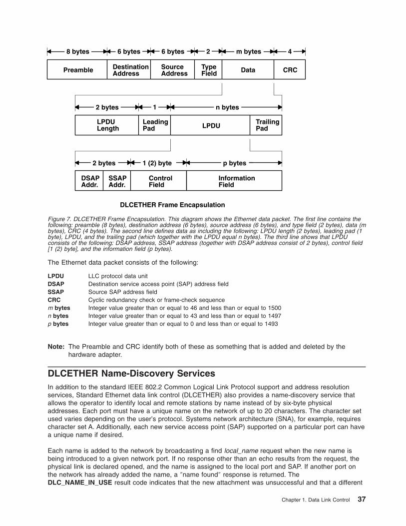
The Ethernet data packet consists of the following:
LPDU LLC protocol data unit
DSAP Destination service access point (SAP) address field
SSAP Source SAP address field
CRC Cyclic redundancy check or frame-check sequence
m bytes Integer value greater than or equal to 46 and less than or equal to 1500
n bytes Integer value greater than or equal to 43 and less than or equal to 1497
p bytes Integer value greater than or equal to 0 and less than or equal to 1493
Note: The Preamble and CRC identify both of these as something that is added and deleted by the
hardware adapter.
DLCETHER Name-Discovery Services
In addition to the standard IEEE 802.2 Common Logical Link Protocol support and address resolution
services, Standard Ethernet data link control (DLCETHER) also provides a name-discovery service that
allows the operator to identify local and remote stations by name instead of by six-byte physical
addresses. Each port must have a unique name on the network of up to 20 characters. The character set
used varies depending on the user’s protocol. Systems network architecture (SNA), for example, requires
character set A. Additionally, each new service access point (SAP) supported on a particular port can have
a unique name if desired.
Each name is added to the network by broadcasting a find local_name request when the new name is
being introduced to a given network port. If no response other than an echo results from the request, the
physical link is declared opened, and the name is assigned to the local port and SAP. If another port on
the network has already added the name, a ″name found″ response is returned. The
DLC_NAME_IN_USE result code indicates that the new attachment was unsuccessful and that a different
DSAPAddr.
SSAPAddr.
ControlField
InformationField
2 bytes p bytes1 (2) byte
LeadingPad
TrailingPadLPDU
LPDULength
2 bytes n bytes
DestinationAddress
SourceAddress
TypeFieldPreamble Data CRC
8 bytes 6 bytes 6 bytes m bytes2 4
1
DLCETHER Frame Encapsulation
Figure 7. DLCETHER Frame Encapsulation. This diagram shows the Ethernet data packet. The first line contains the
following: preamble (8 bytes), destination address (6 bytes), source address (6 bytes), and type field (2 bytes), data (m
bytes), CRC (4 bytes). The second line defines data as including the following: LPDU length (2 bytes), leading pad (1
byte), LPDU, and the trailing pad (which together with the LPDU equal n bytes). The third line shows that LPDU
consists of the following: DSAP address, SSAP address (together with DSAP address consist of 2 bytes), control field
[1 (2) byte], and the information field (p bytes).
Chapter 1. Data Link Control 37
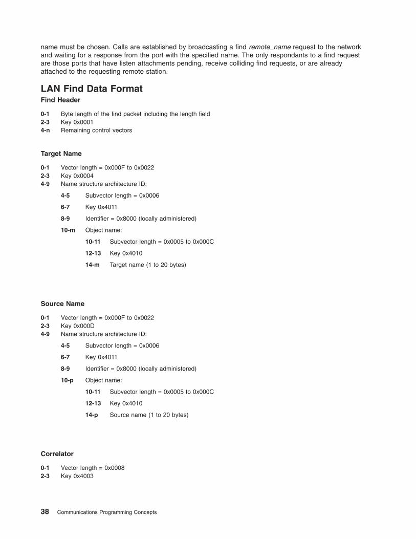
name must be chosen. Calls are established by broadcasting a find remote_name request to the network
and waiting for a response from the port with the specified name. The only respondants to a find request
are those ports that have listen attachments pending, receive colliding find requests, or are already
attached to the requesting remote station.
LAN Find Data Format
Find Header
0-1 Byte length of the find packet including the length field
2-3 Key 0x0001
4-n Remaining control vectors
Target Name
0-1 Vector length = 0x000F to 0x0022
2-3 Key 0x0004
4-9 Name structure architecture ID:
4-5 Subvector length = 0x0006
6-7 Key 0x4011
8-9 Identifier = 0x8000 (locally administered)
10-m Object name:
10-11 Subvector length = 0x0005 to 0x000C
12-13 Key 0x4010
14-m Target name (1 to 20 bytes)
Source Name
0-1 Vector length = 0x000F to 0x0022
2-3 Key 0x000D
4-9 Name structure architecture ID:
4-5 Subvector length = 0x0006
6-7 Key 0x4011
8-9 Identifier = 0x8000 (locally administered)
10-p Object name:
10-11 Subvector length = 0x0005 to 0x000C
12-13 Key 0x4010
14-p Source name (1 to 20 bytes)
Correlator
0-1 Vector length = 0x0008
2-3 Key 0x4003
38 Communications Programming Concepts
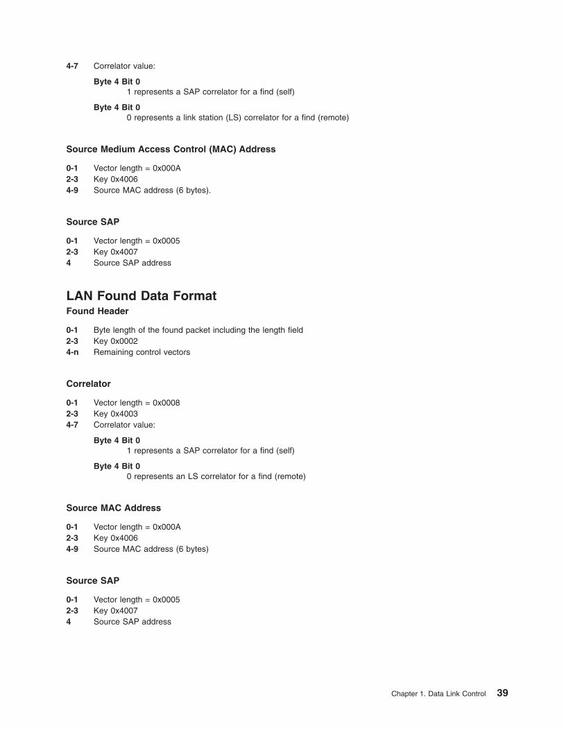
4-7 Correlator value:
Byte 4 Bit 0
1 represents a SAP correlator for a find (self)
Byte 4 Bit 0
0 represents a link station (LS) correlator for a find (remote)
Source Medium Access Control (MAC) Address
0-1 Vector length = 0x000A
2-3 Key 0x4006
4-9 Source MAC address (6 bytes).
Source SAP
0-1 Vector length = 0x0005
2-3 Key 0x4007
4 Source SAP address
LAN Found Data Format
Found Header
0-1 Byte length of the found packet including the length field
2-3 Key 0x0002
4-n Remaining control vectors
Correlator
0-1 Vector length = 0x0008
2-3 Key 0x4003
4-7 Correlator value:
Byte 4 Bit 0
1 represents a SAP correlator for a find (self)
Byte 4 Bit 0
0 represents an LS correlator for a find (remote)
Source MAC Address
0-1 Vector length = 0x000A
2-3 Key 0x4006
4-9 Source MAC address (6 bytes)
Source SAP
0-1 Vector length = 0x0005
2-3 Key 0x4007
4 Source SAP address
Chapter 1. Data Link Control 39
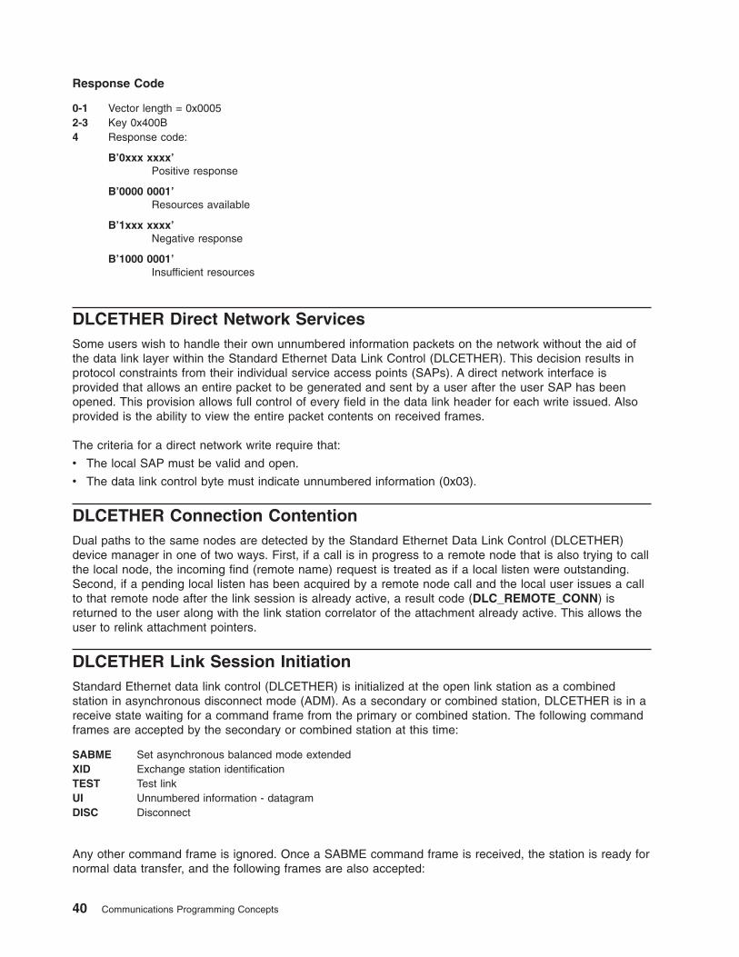
Response Code
0-1 Vector length = 0x0005
2-3 Key 0x400B
4 Response code:
B’0xxx xxxx’
Positive response
B’0000 0001’
Resources available
B’1xxx xxxx’
Negative response
B’1000 0001’
Insufficient resources
DLCETHER Direct Network Services
Some users wish to handle their own unnumbered information packets on the network without the aid of
the data link layer within the Standard Ethernet Data Link Control (DLCETHER). This decision results in
protocol constraints from their individual service access points (SAPs). A direct network interface is
provided that allows an entire packet to be generated and sent by a user after the user SAP has been
opened. This provision allows full control of every field in the data link header for each write issued. Also
provided is the ability to view the entire packet contents on received frames.
The criteria for a direct network write require that:
v The local SAP must be valid and open.
v The data link control byte must indicate unnumbered information (0x03).
DLCETHER Connection Contention
Dual paths to the same nodes are detected by the Standard Ethernet Data Link Control (DLCETHER)
device manager in one of two ways. First, if a call is in progress to a remote node that is also trying to call
the local node, the incoming find (remote name) request is treated as if a local listen were outstanding.
Second, if a pending local listen has been acquired by a remote node call and the local user issues a call
to that remote node after the link session is already active, a result code (DLC_REMOTE_CONN) is
returned to the user along with the link station correlator of the attachment already active. This allows the
user to relink attachment pointers.
DLCETHER Link Session Initiation
Standard Ethernet data link control (DLCETHER) is initialized at the open link station as a combined
station in asynchronous disconnect mode (ADM). As a secondary or combined station, DLCETHER is in a
receive state waiting for a command frame from the primary or combined station. The following command
frames are accepted by the secondary or combined station at this time:
SABME Set asynchronous balanced mode extended
XID Exchange station identification
TEST Test link
UI Unnumbered information - datagram
DISC Disconnect
Any other command frame is ignored. Once a SABME command frame is received, the station is ready for
normal data transfer, and the following frames are also accepted:
40 Communications Programming Concepts
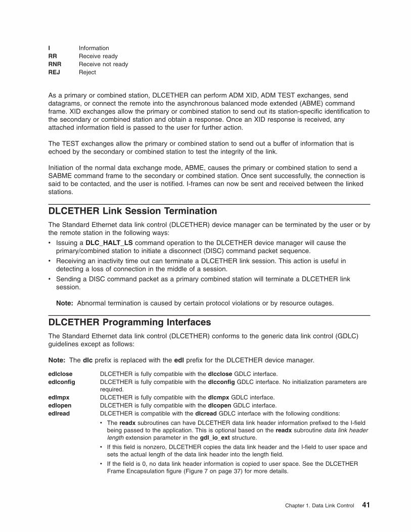
I Information
RR Receive ready
RNR Receive not ready
REJ Reject
As a primary or combined station, DLCETHER can perform ADM XID, ADM TEST exchanges, send
datagrams, or connect the remote into the asynchronous balanced mode extended (ABME) command
frame. XID exchanges allow the primary or combined station to send out its station-specific identification to
the secondary or combined station and obtain a response. Once an XID response is received, any
attached information field is passed to the user for further action.
The TEST exchanges allow the primary or combined station to send out a buffer of information that is
echoed by the secondary or combined station to test the integrity of the link.
Initiation of the normal data exchange mode, ABME, causes the primary or combined station to send a
SABME command frame to the secondary or combined station. Once sent successfully, the connection is
said to be contacted, and the user is notified. I-frames can now be sent and received between the linked
stations.
DLCETHER Link Session Termination
The Standard Ethernet data link control (DLCETHER) device manager can be terminated by the user or by
the remote station in the following ways:
v Issuing a DLC_HALT_LS command operation to the DLCETHER device manager will cause the
primary/combined station to initiate a disconnect (DISC) command packet sequence.
v Receiving an inactivity time out can terminate a DLCETHER link session. This action is useful in
detecting a loss of connection in the middle of a session.
v Sending a DISC command packet as a primary combined station will terminate a DLCETHER link
session.
Note: Abnormal termination is caused by certain protocol violations or by resource outages.
DLCETHER Programming Interfaces
The Standard Ethernet data link control (DLCETHER) conforms to the generic data link control (GDLC)
guidelines except as follows:
Note: The dlc prefix is replaced with the edl prefix for the DLCETHER device manager.
edlclose DLCETHER is fully compatible with the dlcclose GDLC interface.
edlconfig DLCETHER is fully compatible with the dlcconfig GDLC interface. No initialization parameters are
required.
edlmpx DLCETHER is fully compatible with the dlcmpx GDLC interface.
edlopen DLCETHER is fully compatible with the dlcopen GDLC interface.
edlread DLCETHER is compatible with the dlcread GDLC interface with the following conditions:
v The readx subroutines can have DLCETHER data link header information prefixed to the I-field
being passed to the application. This is optional based on the readx subroutine data link header
length extension parameter in the gdl_io_ext structure.
v If this field is nonzero, DLCETHER copies the data link header and the I-field to user space and
sets the actual length of the data link header into the length field.
v If the field is 0, no data link header information is copied to user space. See the DLCETHER
Frame Encapsulation figure (Figure 7 on page 37) for more details.
Chapter 1. Data Link Control 41
The following kernel receive packet subroutines always have the DLCETHER data link header information
within the communications memory buffer (mbuf) and can locate it by subtracting the length passed (in the
gdl_io_ext structure) from the data offset field of the mbuf structure.
edlselect DLCETHER is fully compatible with the dlcselect GDLC interface.
edlwrite DLCETHER is compatible with the dlcwrite GDLC interface with the exception that network data
can only be written as an unnumbered information (UI) packet and must have the complete data
link header prefixed to the data. DLCETHER verifies that the local (source) service access point
(SAP) is enabled and that the control byte is UI (0x03). See the DLCETHER Frame Encapsulation
figure (Figure 7 on page 37).
edlioctl DLCETHER is compatible with the dlcioctl GDLC interface with conditions on these operations
(described in the following sections):
v “DLC_ENABLE_SAP”
v “DLC_START_LS” on page 43
v “DLC_ALTER” on page 43
v “DLC_QUERY_SAP” on page 43
v “DLC_QUERY_LS” on page 43
v “DLC_ENTER_SHOLD” on page 44
v “DLC_EXIT_SHOLD” on page 44
v “DLC_ADD_GRP” on page 44
v “DLC_ADD_FUNC_ADDR” on page 44
v “DLC_DEL_FUNC_ADDR” on page 44
v “DLC_DEL_GRP” on page 44
v “IOCINFO” on page 44
DLC_ENABLE_SAP
The ioctl subroutine argument structure for enabling a SAP (dlc_esap_arg) has the following specifics:
v The grp_addr field is a 6-byte value as specified in the draft IEEE Standard 802.3 specifications. Octet
grp_addr[0] specifies the most significant byte and octet grp_addr[5] specifies the least significant byte.
Each octet of the address field is transmitted, least significant bit first. Group addresses sometimes are
called multicast addresses. An example of an group address follows:
0x0900_2B00_0004
Note: No checks are made by the DLCETHER device manager as to whether a received packet was
accepted by the adapter due to a preset network address or group address.
v The max_ls (maximum link station) field cannot exceed a value of 255.
v The following common SAP flags are not supported:
ENCD Indicates a synchronous data link control (SDLC) serial encoding.
NTWK Indicates a teleprocessing network type.
LINK Indicates a teleprocessing link type.
PHYC Indicates a physical network call (teleprocessing).
ANSW Indicates a teleprocessing autocall and autoanswer.
v Group SAPs are not supported, so the num_grp_saps (number of group SAPs) field must be set to 0.
v The laddr_name (local address and name) field and its associated length are only used for name
discovery when the common SAP flag ADDR field is set to 0. When resolve procedures are used (that
is, the ADDR flag is set to 1), DLCETHER obtains the local network address from the device handler
and not from the dlc_esap_arg structure.
v The local_sap (local service access point) field can be set to any value except the null SAP (0x00) or
the name-discovery SAP (0xFC). Also, the low-order bit must be set to 0 (B`nnnnnnn0’) to indicate an
individual address.
42 Communications Programming Concepts
v No protocol-specific data area is required for the DLCETHER device manager to enable a SAP.
DLC_START_LS
The ioctl subroutine argument structure for starting a link station (dlc_sls_arg) has the following specifics:
v These common link station flags are not supported:
STAT Indicates a station type for SDLC.
NEGO Indicates a negotiable station type for SDLC.
v The raddr_name (remote address or name) field is used only for outgoing calls when the
DLC_SLS_LSVC common link station flag is active.
v The maxif (maximum I-field) length can be set to any value greater than 0. See the DLCETHER Frame
Encapsulation figure (Figure 7 on page 37) for supported byte lengths. The DLCETHER device manager
adjusts this value to a maximum of 1493 bytes if set too large.
v The rcv_wind (receive window) field can be set to any value between 1 and 127, inclusive. The
recommended value is 127.
v The xmit_wind (transmit window) field can be set to any value between 1 and 127, inclusive. The
recommended value is 26.
v The rsap (remote SAP) field can be set to any value except null SAP (0x00) or the name-discovery SAP
(0xFC). Also, the low-order bit must be set to 0 (B`nnnnnnn0’) to indicate an individual address.
v The max_repoll field can be set to any value between 1 and 255, inclusive. The recommended value is
8.
v The repoll_time field is defined in increments of 0.5 seconds and can be set to any value between 1
and 255, inclusive. The recommended value is 2, giving a time-out duration of 1 to 1.5 seconds.
v The ack_time (acknowledgment time) field is defined in increments of 0.5 seconds and can be set to
any value between 1 and 255, inclusive. The recommended value is 1, giving a time-out duration of 0.5
to 1 second.
v The inact_time (inactivity time) field is defined in increments of 1 second, and can be set to any value
between 1 and 255, inclusive. The recommended value is 48, giving a time-out duration of 48 to 48.5
seconds.
v The force_time (force halt time) field is defined in increments of 1 second, and can be set to any value
between 1 and 16383, inclusive. The recommended value is 120, giving a time-out duration of
approximately 2 minutes.
v No protocol-specific data area is required for the DLCETHER device manager to start a link station.
DLC_ALTER
The ioctl subroutine argument structure for altering a link station (dlc_alter_arg) has the following
specifics:
v These alter flags are not supported:
RTE Alters routing.
SM1, SM2 Sets synchronous data link control (SDLC) control mode.
v No protocol-specific data area is required for the DLCETHER device manager to alter a link station.
DLC_QUERY_SAP
The device driver-dependent data returned from DLCETHER for this ioctl operation is the ent_ndd_stats_t
structure defined in the /usr/include/sys/cdli_entuser.h file.
DLC_QUERY_LS
No protocol-specific data area is supported by DLCETHER for this ioctl operation.
Chapter 1. Data Link Control 43
DLC_ENTER_SHOLD
The enter_short_hold option is not supported by the DLCETHER device manager.
DLC_EXIT_SHOLD
The exit_short_hold option is not supported by the DLCETHER device manager.
DLC_ADD_GRP
The add_group or multicast address option is supported by the DLCETHER device manager as a six-byte
value as described above in DLC_ENABLE_SAP (group address) ioctl operation.
DLC_ADD_FUNC_ADDR
The add_functional_address option is not supported by DLCETHER.
DLC_DEL_FUNC_ADDR
The delete_functional_address option is not supported by DLCETHER.
DLC_DEL_GRP
The delete group or multicast option is supported by the DLCETHER device manager. The address being
removed must match an address that was added with a DLC_ENABLE_SAP or DLC_ADD_GRP ioctl
operation.
IOCINFO
The ioctype variable returned is defined as DD_DLC definition and the subtype returned is
DS_DLCETHER.
Synchronous Data Link Control Overview
Synchronous data link control (DLCSDLC) is one of the generic data link controls. It provides an access
procedure for transparent and code-independent information interchange across teleprocessing and data
networks, as defined in the SDLC Concepts document.
The list of architecture supported by DLCSDLC includes:
v Normal disconnected mode (NDM) and normal response mode (NRM)
v Two-way alternate (half-duplex) data flow
v Secondary station point-to-point, multipoint, and multi-multipoint configurations
v Primary station point-to-point and multipoint configurations
v Modulo 8 transmit-and-receive sequence counts
v Nonextended (single-byte) station address.
For more information about DLCSDLC controls, see:
v “DLCSDLC Device Manager Functions” on page 45
v “DLCSDLC Protocol Support” on page 45
v “DLCSDLC Programming Interfaces” on page 48
v “DLCSDLC Asynchronous Function Subroutine Calls” on page 51
44 Communications Programming Concepts
DLCSDLC Device Manager Functions
Synchronous data link control (SDLC) is split between a physical adapter with its associated device
handler and a data link control (DLC) component. The synchronous data link control (DLCSDLC) device
manager is responsible for functions that include:
v Sequencing information frames
v Creating address and control for transmit frames
v Servicing control for receive frames
v Handling repoll and inactivity time outs
v Generating frame-rejects
v Handling transmit windows
v Handling reliability counters, availability counters, serviceability counters, error logs, and link traces.
The device handler and adapter are jointly responsible for the remaining SDLC functions:
v Recognizing station addresses
v Encoding and decoding non-return-to-zero (inverted) recording (NRZI) and non-return-to-zero (NRZ)
v Inserting and deleting 0 bits
v Generating and checking frame-check sequences
v Generating and checking flags and pads
v Filling interframe time
v Handling line-attachment protocols, such as RS-232C, X.21, and Smartmodem
v Handling fail-safe time outs
v Handling autoresponse for nonproductive supervisory command frames.
DLCSDLC Protocol Support
The synchronous data link control (SDLC) device manager (DLCSDLC) supports SDLC protocol and state
tables.
Station Types
DLCSDLC supports two station types:
v Primary stations responsible for control of data interchange on the link
v Secondary, or subordinate, stations on the link
Operation Modes
DLCSDLC supports two modes of operation:
v Single-physical unit (PU) mode
v Multiple-PU mode
Single-PU mode allows a single open per port. In this mode, only one DLC_ENABLE_SAP ioctl operation
is allowed per port. All additional DLC_ENABLE_SAP ioctl operations are rejected with an errno value of
EINVAL. In addition, only one file descriptor can be used to issue read, write, and ioctl operations. When
multiple applications wish to use the same port, only one application can obtain the file descriptor, making
it difficult to share the port.
SDLC multiple-PU secondary support allows multiple secondary stations (up to 254) to occupy a single
physical port, and operate concurrently by multiplexing on the single-byte link-station address field found in
each receive packet. Multiple-PU support also allows multiple applications to issue opens and
DLC_ENABLE_SAP and DLC_START_LS ioctl operations on the same physical port, independent of
other applications on that port.
Chapter 1. Data Link Control 45
For migration purposes, multiple-PU support is activated only if the first open per port to the /dev/dlcsdlc
file is extended with the dlc_open_ext structure and the maxsaps (maximum service access points) field
is set to a value between 2 and 127, inclusive. This type of open operation allows DLCSDLC to switch
from the original single-PU operation to multiple-PU operation. Only secondary link stations are allowed to
be started in multiple-PU mode.
One channel owns the service access point (SAP) on a single port since a single network configuration is
supported for each port. However, subsequent DCL_ENABLE_SAP ioctl operations issued when the port
is already activated fail with an errno value of EBUSY instead of EINVAL. The current SAP correlator
value (gdlc_sap_corr) is returned on these EBUSY conditions, enabling subsequent commands to be
issued to DLCSDLC, even though a different user process may own the SAP.
Any address between 0x01 and 0xFE may be specified as the local secondary link station address.
Secondary station address 0x00 is not valid. Station address 0xFF is reserved for broadcast
communication. Any packets received with address 0xFF are passed to a single active link station for
subsequent response on a port. Any additional active link stations on that port do not receive the packet.
Transmission Frames
All communication between the local and remote stations is accomplished by the transmission of frames.
The SDLC frame format consists of:
Unique flag sequence (B`01111110’) 1 byte
Station link address field 1 byte
Control field 1 byte
Information field n bytes
Frame check sequence 2 bytes
Unique flag sequence (B`01111110’) 1 byte
Three kinds of SDLC frames exist: information, supervisory, and unnumbered. Information frames transport
sequenced user data between the local and remote stations. Supervisory frames carry control parameters
relative to the sequenced data transfer. Unnumbered frames transport the controls relative to
nonsequenced transfers.
Response Modes
Both normal disconnect mode (NDM) and normal response mode (NRM) are supported. NDM is entered
by default whenever a session is initiated, and is switched to NRM only after completion of the set normal
response mode/unnumbered acknowledge (SNRM/UA) command sequence. Once operating in NRM,
information frames containing user data can be transferred. NRM then remains active until termination of
the SDLC session, which occurs due to the disconnect/unnumbered acknowledge (DISC/UA) command
sequence or a major link error. Once termination is complete, SDLC activity halts, and the NDM/NRM
modes are not re-entered until another session is initiated.
Station Link Address Field
The supported station link address field is nonextended and consists of either the all-stations (broadcast)
address or a single unique 8-bit value other than the all-zeros (null) address. The secondary station’s
address can be any value from 1 through 254. Address value 255 (broadcast) is only used by the primary
station for initial contact of a point-to-point secondary station type, where the secondary’s address is
unknown. Once contact has been made, the secondary station’s returned address is used exclusively for
the remainder of the session.
Control Field (Commands Supported)
All commands are generated by the primary station for the secondary station. Each command carries the
poll indicator to request immediate response, except when sending multiple information frames.
46 Communications Programming Concepts
Information frames that are concatenated have the poll indicator turned on in the last frame of the burst.
The commands supported are:
Information Sends sequenced user data from the primary station to the secondary
station, and acknowledges any received information frames.
Receive Ready Indicates that receive storage is available and acknowledges any
received information frames. This receive ready command is a
supervisory command.
Receive Not Ready Indicates receive storage is not available and acknowledges any
received information frames. The receive not ready command is a
supervisory command.
Disconnect Requests the logical and physical disconnection of the link. The
disconnect command is an unnumbered command.
Set Normal Response Mode Requests entry into normal response mode and resets the information
sequence counts. The setnormal response mode command is an
unnumbered command.
Test Solicits an echoed TEST response from the secondary station and can
carry an optional information field. The test command is an
unnumbered command.
Exchange Station Identification Solicits an exchange identification (XID) response that contains either
the station identification of the secondary station or link negotiation
information that allows the alteration of the primary or secondary
relationship by the user. The exchange station identification
command is an unnumbered command.
Control Field (Responses Supported)
All responses are generated by the secondary station for the primary station. Each response carries the
final indicator to specify send completion, except when sending multiple information frames. Information
frames that are concatenated have the final indicator on in the last frame of the burst. The responses
supported are:
Information Sends sequenced user data from the secondary station to the primary
station. It also acknowledges any received information frames.
Receive Ready Indicates receive storage is available and acknowledges any received
information frames. The receive ready response is a supervisory
response.
Receive Not Ready Indicates receive storage is not available and acknowledges any
received information frames. The receive not ready response is a
supervisory response.
Frame Reject Indicates that the secondary station detects a problem in a command
frame that otherwise had a valid frame check sequence in normal
response mode. The frame reject response is an unnumbered
response. The types of frame reject supported are:
0x01 Incorrect or nonimplemented command received.
0x03 Incorrect information field attached to command received.
0x04 I-field exceeded buffer capacity (this value is not supported by
DLCSDLC). Each overflowed receive buffer is passed to the
user with an indication of overflow.
0x08 Number received (NR) sequence count is out of range.
Disconnected Mode Indicates that the secondary station is in normal disconnect mode. The
disconnected mode response is an unnumbered response.
Unnumbered Acknowledge Acknowledges receipt of the set normal response mode or disconnect
commands that were sent by the primary station. The unnumbered
acknowledge response is an unnumbered response.
Chapter 1. Data Link Control 47
Test Echoes the TEST command frame sent by the primary station, and
carries the information field received only if sufficient storage is
available. The test response is an unnumbered response.
Exchange Station Identification Contains the station identification of the secondary station. The
exchange station identification response is an unnumbered response.
DLCSDLC Programming Interfaces
The synchronous data link control (SDLC) device manager (DLCSDLC) conforms to the generic data link
control (GDLC) guidelines except where noted in the following list. Additional structures and definitions for
DLCSDLC can be found in the /usr/include/sys/sdlextcb.h file.
Note: The GDLC entry-point prefix dlc is replaced with the sdl prefix to denote DLCSDLC device
manager operation.
sdlclose DLCSDLC is fully compatible with the dlcclose GDLC interface.
sdlconfig DLCSDLC is fully compatible with the dlcconfig GDLC interface. No initialization parameters are
required.
sdlmpx DLCSDLC is fully compatible with the dlcmpx GDLC interface.
sdlopen DLCSDLC is fully compatible with the dlcopen GDLC interface with the following conditions:
v Single-physical unit (PU) mode allows only one open per port. The open can come from either
an application or kernel user, but multiple users cannot share the same port. Single-PU mode is
entered by issuing the open without an extension, or by issuing an extended open with the
maxsaps (maximum service access points) field set to a value of 0 or 1. Single-PU mode is the
default.
v Multiple-PU mode allows multiple processes to open a secondary port. Multiple-PU mode is
entered by issuing an extended open with the maxsaps field set to a value greater than 1.
Note: Only one user process is allowed to open a primary port.
sdlread DLCSDLC is compatible with the dlcread GDLC interface, with the following conditions:
v Network data is defined as any data received from data communication equipment (DCE) that is
not specific to the SDLC session protocol. Examples are X.21 call-progress signals or
Smartmodem call-establishment messages. This data must be interpreted differently, depending
on the physical attachment in use.
v Datagram receive data is not supported.
sdlselect DLCSDLC is fully compatible with the dlcselect GDLC interface.
sdlwrite DLCSDLC is compatible with the dlcwrite GDLC interface, with the exception that network data
and datagram data are not supported in the send direction. Network data such as X.21 or
Smartmodem call-establishment data is sent using the DLC_ENABLE_SAP ioctl operation.
sdlioctl DLCSDLC is compatible with the dlcioctl GDLC interface, with conditions on the following
operations:
v “DLC_ENABLE_SAP” on page 49
v “DLC_START_LS” on page 49
v “DLC_ALTER” on page 51
v “DLC_QUERY_SAP” on page 51
v “DLC_QUERY_LS” on page 51
v “DLC_ENTER_SHOLD” on page 51
v “DLC_EXIT_SHOLD” on page 51
v “DLC_ADD_GRP” on page 51
v “DLC_ADD_FUNC_ADDR” on page 51
v “DLC_DEL_FUNC_ADDR” on page 51
v “IOCINFO” on page 51
The following sections describe these conditions.
48 Communications Programming Concepts
DLC_ENABLE_SAP
DLCSDLC supports two modes of operation:
v Single-PU mode is entered through the open to DLCSDLC. In this mode, only one DLC_ENABLE_SAP
ioctl operation is allowed per port. All additional DLC_ENABLE_SAP ioctl operations are rejected with
an errno value of EINVAL.
v Multiple-PU mode is also entered through the open to DLCSDLC. In this mode, up to 254
DLC_ENABLE_SAP ioctl operations can be issued. The first DLC_ENABLE_SAP ioctl operation
establishes the physical connection. All subsequent DLC_ENABLE_SAP ioctls return an errno value of
EBUSY, but pass back the gdlc_sap_corr value of the first successful DLC_ENABLE_SAP so that link
stations can be started.
The ioctl subroutine argument structure for enabling a service access point (SAP) (dlc_esap_arg) has the
following specifics:
v The func_addr_mask (function address mask) field is not supported.
v The grp_addr (group address) field is not supported.
v The max_ls (maximum link stations) field cannot exceed a value of 254 on a multidrop primary link or a
multiple-PU secondary link, and cannot exceed 1 on a point-to-point link.
v The following common SAP flag is not supported:
ADDR Specifies local address or name indicator.
v The laddr_name (local address or name) field is not supported, so the length of the local address/name
field is ignored.
v Group SAPs are not supported, so the num_grp_saps (number of group SAPs) and grp_sap (group
SAP - n) fields are ignored.
v The local_sap (local service access point) field is not supported and is ignored.
v The protocol specific data area is identical to the start device structure required by the multiprotocol
device handler. See the /usr/include/sys/mpqp.h file and the t_start_dev structure for more details.
DLC_START_LS
DLCSDLC supports up to 254 concurrent link stations (LSs) on a single port when it operates as a
multidrop primary node or a multiple-PU secondary node. Only one LS can be started when DLCSDLC
operates on a point-to-point connection, or when it is a single-PU secondary node on a multidrop
connection.
v The following common link station flags are not supported:
LSVC LS virtual call is ignored.
ADDR Address indicator must be set to 1 to indicate that no name-discovery services are provided.
v The len_raddr_name (length of remote address or name) field must be set to 1.
v The raddr_name (remote address or name) field is the one-byte station address of the remote node in
hexadecimal.
v The maxif (maximum I-field length) field can be set to any value greater than 0. DLCSDLC adjusts this
value to a maximum of 4094 bytes if set too large.
v The rcv_wind (maximum receive window) field can be set to any value from 1 to 7. The recommended
value is 7.
v The xmit_wind (maximum transmit window) field can be set to any value from 1 to 7. The recommended
value is 7.
v The rsap (remote SAP) field is ignored.
v The rsap_low (remote SAP low range) field is ignored.
v The rsap_high (remote SAP high range) field is ignored.
Chapter 1. Data Link Control 49
v The max_repoll field can be set to any value from 1 to 255, inclusive. The recommended value is 15.
v The repoll_time field is defined in increments of 0.1 second and can be set to any value from 1 to 255.
The recommended value is 30, giving a time-out duration of approximately 30 seconds.
v The ack_time (acknowledgment time) field is ignored.
v The inact_time (inactivity time) field is defined in increments of 1 second and can be set to any value
from 1 to 255, inclusive. The recommended value is 30, giving a time-out duration of approximately 30
seconds.
v The force_time (force halt time) field is defined in increments of 1 second and can be set to any value
from 1 to 16383, inclusive. The recommended value is 120, giving a time-out duration of approximately
2 minutes.
v The following protocol-specific data area must be appended to the generic start LS argument structure
(dlc_sls_arg). This structure provides DLCSDLC with additional protocol-specific configuration
parameters:
struct sdl_start_psd
}
uchar_t duplex; /*link station xmit/receive capability */
uchar_t secladd; /* secondary station local address */
uchar_t prirpth; /* primary repoll timeout threshold */
uchar_t priilto; /* primary idle list timeout */
uchar_t prislto; /* primary slow list timeout */
uchar_t retxct; /* retransmit count ceiling */
uchar_t retxth; /* retransmit count threshold */
uchar_t reserved; /* currently not used */
{;
The protocol-specific parameters are as follows:
duplex Specifies LS transmit-receive capability. This field must be set to 0, indicating two-way alternating
capability.
secladd Specifies the secondary station link address of the local station. If the local station is negotiable, this
address is used only if the local station becomes a secondary station from role negotiation. This field
overlays the mpioctl (CIO_START) poll address variable, poll_addr.
prirpth Specifies primary repoll threshold. This field specifies the number of contiguous repolls that cause the
local primary to log a temporary error. Any value from 1 to 100 can be specified. The recommended
value is 10.
priilto Specifies primary idle list time out. If the primary station has specified the Hold Link on Inactivity
parameter and then discovers that a secondary station is not responding, the primary station places
that secondary station on an idle list. The primary station polls a station on the idle list less frequently
than the other secondary stations to avoid tying up the network with useless polls. This field sets the
amount of time (in seconds) that the primary station should wait between polls to stations on the idle
list. Any value from 1 to 255, inclusive, may be specified. The recommended value is 60, giving a
time-out duration of approximately 60 seconds.
prislto Specifies primary slow list time out. When the primary station discovers that communication with a
secondary station is not productive, it places that station on a slow list. The primary station polls a
station on the slow list less frequently than the other secondary stations to avoid tying up the network
with useless polls. This field sets the amount of time (in seconds) that the primary station should wait
between polls to stations on the slow list. Any value from 1 to 255, inclusive, can be specified. The
recommended value is 20, giving a time-out duration of approximately 20 seconds.
retxct Indicates retransmit count. This field specifies the number of contiguous information frame bursts
containing the same data that the local station retransmits before it declares a permanent transmission
error. Any value from 1 to 255, inclusive, can be specified. The recommended value is 10.
retxth Indicates retransmit threshold. This field specifies the maximum number of information frame
retransmissions allowed as a percentage of total information frame transmission (sampled only after a
block of information frames has been sent). If the number of retransmissions exceeds the specified
percentage, the system declares a temporary error. Any value from 1 to 100% can be specified. The
recommended value is 10%.
50 Communications Programming Concepts
DLC_ALTER
Specifics for the ioctl subroutine argument structure to alter a link station (dlc_alter_arg) include:
v These alter flags are not supported:
AKT Alter acknowledgment time out.
RTE Alter routing.
v The act_time (acknowledge time out) field is ignored.
v The routing data field is ignored.
v No protocol-specific data area is required for DLCSDLC to alter its configuration.
DLC_QUERY_SAP
No device driver-dependent data area is supported by DLCSDLC for the query sap ioctl operation.
DLC_QUERY_LS
No protocol-specific data area is supported by DLCSDLC for the query link station ioctl operation.
DLC_ENTER_SHOLD
DLCSDLC does not currently support the enter_short_hold option.
DLC_EXIT_SHOLD
DLCSDLC does not currently support the exit_short_hold option.
DLC_ADD_GRP
The add_group or multicast address option is not supported by DLCSDLC.
DLC_ADD_FUNC_ADDR
The add_functional_address option is not supported by DLCSDLC.
DLC_DEL_FUNC_ADDR
The delete_functional_address option is not supported by DLCSDLC.
IOCINFO
The ioctype variable is defined as a DD_DLC definition and the subtype returned is DS_DLCSDLC.
DLCSDLC Asynchronous Function Subroutine Calls
Datagram data received is not supported, and the synchronous data link control (SDLC) device manager
(DLCSDLC) never calls the rcvd_fa function.
DLCSDLC is compatible with each of the other asynchronous function subroutines for the kernel user.
Qualified Logical Link Control (DLCQLLC) Overview
Qualified logical link control (QLLC) data link control (DLCQLLC) is one of the generic data link controls. It
provides an access procedure to attach to X.25 packet-switching networks.
DLCQLLC fully supports the 1980 and 1984 versions of the CCITT recommendation relevant to Systems
Network Architecture (SNA)-to-SNA connections. It allows point-to-point connections over an X.25 network
between a pair of primary and secondary link stations.
Chapter 1. Data Link Control 51
DLCQLLC provides two-way alternate (half-duplex) data flow over switched or permanent virtual circuits.
For more information about the DLCQLLC controls, see:
v “DLCQLLC Device Manager Functions”
v “DLCQLLC Programming Interfaces”
v “DLCQLLC Asynchronous Function Subroutine Calls” on page 57
DLCQLLC supports the following X.25 optional facilities:
v Modulo 8/128 packet sequence numbering
v Closed user groups
v Recognized private operating agencies
v Network user identification
v Reverse charging
v Packet-size negotiation
v Window-size negotiation
v Throughput class negotiation
DLCQLLC Device Manager Functions
DLCQLLC, as described in the X.25 Interface for Attaching SNA Nodes to Packet-Switch Data Networks
and X.25 1984 Interface Architectural Reference, is split between a physical adapter with its associated
device handler and a data link control component. The DLC component is responsible for the following
QLLC functions:
v Creation of address and control for transmit frames
v Service of control for receive frames
v Repoll and inactivity time outs
v Frame-reject generation
v Facility negotiation
The data link control and device handler components are jointly responsible for:
v Establishment of an X.25 virtual circuit
v Clearing of an X.25 virtual circuit
v Notification of exceptional conditions to higher levels
v Reliability/availability/serviceability (RAS) counters, error logs, and link traces
The device handler and adapter are jointly responsible for:
v Packetization of I-frames
v Packet sequencing
v Link access protocol balance (LAPB) procedures as defined by CCITT recommendation X.25
v Physical-line attachment protocols
DLCQLLC Programming Interfaces
QLLC data link control (DLCQLLC) conforms to the GDLC guidelines except where noted below.
Note: The dlc prefix is replaced with qlc prefix for DLCQLLC device manager.
qlcclose DLCQLLC is fully compatible with the dlcclose GDLC interface.
qlcconfig DLCQLLC is fully compatible with the dlcconfig GDLC interface. No initialization parameters are
required.
qlcmpx DLCQLLC is fully compatible with the dlcmpx GDLC interface.
52 Communications Programming Concepts
qlcopen DLCQLLC is fully compatible with the dlcopen GDLC interface.
qlcread DLCQLLC is compatible with the dlcread GDLC interface, except that network data and datagram
receive data are not supported.
qlcselect DLCQLLC is fully compatible with the dlcselect GDLC interface.
qlcwrite DLCQLLC is compatible with the dlcwrite GDLC interface with the exception that network data and
datagram data are not supported.
qlcioctl DLCQLLC is compatible with the dlcioctl GDLC interface with conditions on the following
operations:
v “DLC_ENABLE_SAP”
v “DLC_START_LS”
v “DLC_ALTER” on page 56
v “DLC_QUERY_SAP” on page 56
v “DLC_QUERY_LS” on page 56
v “DLC_ENTER_SHOLD” on page 57
v “DLC_EXIT_SHOLD” on page 57
v “DLC_ADD_GRP” on page 57
v “DLC_ADD_FUNC_ADDR” on page 57
v “DLC_DEL_FUNC_ADDR” on page 57
v “IOCINFO” on page 57
The following sections describe these conditions.
DLC_ENABLE_SAP
The ioctl subroutine argument structure for enabling a service access point (SAP), dlc_esap_arg, has the
following specifics:
v The function address mask field is not supported.
v The group address field is not supported.
v The max_ls field cannot exceed a value of 255.
v The common SAP flags are not supported.
v Group SAPs are not supported, so the number of group SAPs and group SAP-n fields are ignored.
v The local SAP field is not supported and is ignored.
v The protocol-specific data area is not required.
DLC_START_LS
DLCQLLC supports up to 255 concurrent link stations (LS) on a single SAP. Each active link station
becomes a virtual circuit to the X.25 device. The actual number of possible link stations may be less than
255, based on the number of virtual circuits available from the X.25 device.
The ioctl subroutine argument structure for starting an LS, dlc_sls_arg, has the following specifics:
v The following common link station flag is not supported:
ADDR The address indicator flag is ignored.
v The raddr_name (remote address) field is used only for outgoing calls when the DLC_SLS_LSVC
common link station flag is active. Two formats are supported:
– For an X.25 switched virtual circuit, the raddr_name field is the remote’s X.25 network user address
(NUA), encoded as a string of ASCII digits.
– For an X.25 permanent virtual circuit, the raddr_name field is the logical channel number, encoded
as a string of ASCII digits prefaced by the lowercase letter p or an uppercase P.
Chapter 1. Data Link Control 53
Examples of valid remote addresses are:
Switched Virtual Circuit 23422560010502
Permanent Virtual Circuit P13
v If the CCITT attribute is set to 1980 when configuring the X.25 adapter, the rcv_window (maximum
receive window) field can be set to any value from 1 to 7. If the CCITT configuration attribute is set to
1984, the rcv_window field can be set to any value from 1 to 128.
v If the CCITT attribute is set to 1980 when configuring the X.25 adapter, the xmit_wind (maximum
transmit window) field can be set to any value from 1 to 7. If the CCITT configuration attribute is set to
1984, the xmit_wind field can be set to any value from 1 to 128.
v The RSAP (remote SAP) field is ignored.
v The RSAP low (remote SAP low range) field is ignored.
v The RSAP high (remote SAP high range) field is ignored.
v The repoll time field is defined in increments of 1 second.
v The ack_time (acknowledgment time) field is ignored.
v A protocol-specific data area must be appended to the generic start link station argument (dlc_sls_arg).
Example of Protocol-Specific Configuration Parameters
The following is an example of a structure that provides DLCQLLC with additional protocol-specific
configuration parameters:
struct qlc_start_psd
{
char listen_name[8];
unsigned short support_level;
struct sna_facilities_type facilities;
};
The protocol-specific parameters are:
listen_name The name of the entry in the X.25 routing list that specifies the characteristics of incoming
calls. This field is used only when a station is listening; that is, when the LSVC flag in the
dlc_sls_arg argument structure is 0.
support_level The version of CCITT recommendation X.25 to support. It must be the same as or earlier
than the CCITT attribute specified for the X.25 adapter.
facilities A structure that contains the X.25 facilities required for use on the virtual circuit for the
duration of this attachment (See “Facilities Structure”).
Facilities Structure
The following is an example of a structure that provides DLCQLLC with facilities parameters:
struct sna_facilities_type
{
unsigned facs:1;
unsigned rpoa:1;
unsigned psiz:1;
unsigned wsiz:1;
unsigned tcls:1;
unsigned cug :1;
unsigned cugo:1;
unsigned res1:1;
unsigned res2:1;
unsigned nui :1;
unsigned :21;
unsigned char recipient_tx_psiz;
unsigned char originator_tx_psiz;
unsigned char recipient_tx_wsiz;
unsigned char originator_tx_wsiz;
unsigned char recipient_tx_tcls;
54 Communications Programming Concepts
unsigned char originator_tx_tcls;
unsigned short reserved;
unsigned short cug_index;
unsigned short rpoa_id_count;
unsigned short rpoa_id[30];
unsigned int nui_length;
char nui_data[109];
};
In the following list of fields, bits with a value of 0 indicate False and with a value of 1 indicate True.
facs Indicates whether there are any facilities being requested. If this field is set to 0, all the remaining facilities
structure is ignored.
rpoa Indicates whether to use a recognized private operating agency.
psiz Indicates whether to use a packet size other than the default.
wsiz Indicates whether to use a window size other than the default.
tcls Indicates whether to use a throughput class other than the default.
cug Indicates whether to supply an index to a closed user group.
cugo Indicates whether to supply an index to a closed user group with outgoing access.
res1 Reserved.
res2 Reserved.
nui Indicates whether network user identification (NUI) is supplied to the network.
The remaining fields provide the values or data associated with each of the above facilities bits that are
set to 1. If the corresponding facilities bit is set to 0, each of these fields is ignored:
recipient_tx_psiz Indicates the coded value of packet size to use when sending data to the node that initiated
the call. The values are coded as follows:
0x06 = 64 octets
0x07 = 128 octets
0x08 = 256 octets
0x09 = 512 octets
0x0A = 1024 octets
0x0B = 2048 octets
0x0C = 4096 octets
Note: 4096-octet packets are allowed only in the 1984 CCITT recommendation. For the
call to be valid, the value of the X.25 CCITT attribute and the corresponding QLLC attribute
must be set to 1984.
originator_tx_psiz Indicates the coded value of packet size to use when sending data from the node that
initiated the call. The values are coded as for the recipient_tx_psiz field. See 55.
recipient_tx_wsiz Reserved for QLLC use.
originator_tx_wsiz Reserved for QLLC use.
Chapter 1. Data Link Control 55
recipient_tx_tcls Indicates the coded values of the throughput class requested for this virtual circuit when
sending data to the node that initiated the call. The values are coded as follows:
0x07 = 1200 bits per second
0x08 = 2400 bits per second
0x09 = 4800 bits per second
0x0A = 9600 bits per second
0x0B = 19200 bits per second
0x0C = 48000 bits per second
originator_tx_tcls Indicates the coded values of the throughput class requested for this virtual circuit when
sending data from the node that initiated the call. The values are coded as for the
recipient_tx_tcls field. See 56.
cug_index Indicates the decimal value of the index of the closed user group (CUG) within which this
call is to be placed. This field is used for either CUG or CUG with outgoing access (CUGO)
facilities.
rpoa_id_count Indicates the number of recognized private operating agency (RPOA) identifiers to supply in
the rpoa_id field. See 56.
rpoa_id Indicates an array of RPOA identifiers that contains the number of identifiers specified in
the rpoa_id_count field. The RPOA identifiers appear in the order in which they will be
traversed when the call is initiated. The content of each array element is the decimal value
of an RPOA identifier. See 56.
nui_length The length, in bytes, of the nui_data field. See 56.
nui_data Network user identification (NUI) data. The contents of this array are defined by the user in
conjunction with the network provider. Note that the maximum allowable X.25 facilities
string is 109 bytes. Even if NUI is the only facility requested, the facility code occupies one
byte, so it is impossible to send more than 108 bytes of NUI data. Each additional facility
requested reduces the space available for NUI data.
DLC_ALTER
The ioctl subroutine argument structure for altering a link station, dlc_alter_arg, has the following
specifics:
v The following alter flags are not supported:
AKT Alter acknowledgment time out.
RTE Alter routing.
XWIN Alter transmit window size.
v The acknowledge time out field is ignored.
v The routing data field is ignored.
v The transmit window size field is ignored.
v No protocol-specific data area is required for DLCQLLC to alter its configuration.
DLC_QUERY_SAP
The device driver dependent data returned from DLCQLLC for this ioctl operation is the cio_stats_t
structure defined in the /usr/include/sys/comio.h file.
DLC_QUERY_LS
There is no protocol specific data area supported by DLCQLLC for the query link station ioctl operation.
56 Communications Programming Concepts
DLC_ENTER_SHOLD
The enter_short_hold option is not supported by DLCQLLC.
DLC_EXIT_SHOLD
The exit_short_hold option is not supported by DLCQLLC.
DLC_ADD_GRP
The add_group or multicast address option is not supported by DLCQLLC.
DLC_ADD_FUNC_ADDR
The add_functional_address option is not supported by DLCQLLC.
DLC_DEL_FUNC_ADDR
The delete_functional_address option is not supported by DLCQLLC.
IOCINFO
The ioctype variable is defined as a DD_DLC definition and the subtype is DS_DLCQLLC.
DLCQLLC Asynchronous Function Subroutine Calls
Network and datagram data are not supported, so the rcvn_fa and rcvd_fa data functions are never
called by DLCQLLC.
DLCQLLC is compatible with each of the other asynchronous function subroutine calls for the kernel user.
Data Link Control FDDI (DLC FDDI) Overview
Fiber distributed data interface (FDDI) data link control (DLC FDDI) is a device manager that follows the
generic interface definition (GDLC). This data link control (DLC) device manager provides a passthrough
capability that allows transparent data flow as well as an access procedure to transfer four types of data
over a FDDI network:
v Datagrams
v Sequenced data
v Identification data
v Logical link controls
The access procedure relies on functions provided by the FDDI Device Handler and the FDDI Network
Bus Master adapter to transfer data with address checking, token generation, or frame check sequences.
The DLC FDDI device manager provides the following functions and services:
v “DLC FDDI Device Manager Functions” on page 58
v “DLC FDDI Protocol Support” on page 59
v “DLC FDDI Name-Discovery Services” on page 60
v “DLC FDDI Direct Network Services” on page 63
v “DLC FDDI Connection Contention” on page 63
v “DLC FDDI Link Sessions” on page 63
v “DLC FDDI Programming Interfaces” on page 64
Chapter 1. Data Link Control 57
DLC FDDI Device Manager Nodes
The DLC FDDI device manager operates between two nodes on a fiber distributed data interface (FDDI)
local area network (LAN), using IEEE 802.2 logical link control (LLC) procedures and control information
as defined in the Token-Ring Network Architecture Reference and media access control procedures as
defined in the ANSI standard publication Fiber Distributed Data Interface-Token Ring Media Access
Control. The DLC FDDI device manager supports:
v Asynchronous disconnected mode (ADM) and asynchronous balanced mode extended (ABME)
v Two-way simultaneous (full-duplex) data flow
v Multiple point-to-point logical attachments on the LAN using network and service access point (SAP)
addresses
v Peer-to-peer relationship with remote station
v Full six-byte addressing
v Both name-discovery and address-resolve services
v Source-routing generation for up to 14 bridge hops
v Asynchronous transmission with eight possible priority levels.
The DLC FDDI provides full-duplex, peer-data transfer capabilities over a FDDI LAN. The FDDI LAN must
use the ANSI X3.139 medium access control (MAC) procedure and a superset of the IEEE 802.2 LLC
protocol as described in the Token-Ring Network Architecture Reference.
Multiple FDDI adapters are supported, with a maximum of 126 SAP users per adapter. A total of 255 link
stations per adapter are supported, which are distributed among the active SAP users.
The term logical link control (LLC) is used to describe the collection of manager, access channel, and link
station subcomponents of a generic data link control GDLC component such as DLC FDDI device
manager, as illustrated in the DLC[TOKEN, 8032, ETHER, or FDDI] Component Structure figure (Figure 4
on page 14).
Each link station (LS) controls the transfer of data on a single logical link. The access channel performs
multiplexing and demultiplexing for message units flowing from the link stations and manager to MAC. The
DLC manager:
v Establishes and terminates connections
v Creates and deletes an LS
v Routes commands to the proper link station.
DLC FDDI Device Manager Functions
The data link control (DLC) fiber distributed data interface (FDDI) device manager and transport medium
use two functional layers, medium access control (MAC) and logical link control (LLC), to maintain reliable
link-level attachments, guarantee data integrity, negotiate exchanges of identification, and support both
connection and non-connection oriented services.
The FDDI adapter and device handler are responsible for the following MAC functions:
v Handling ring-insertion protocol
v Detecting and creating tokens
v Encoding and decoding the serial bit-stream data
v Checking received network and group addresses
v Routing of received frames based on the LLC/MAC/SMT indicator and using the destination service
access point (SAP) address if an LLC frame was received
v Generating frame-check sequences (FCS)
58 Communications Programming Concepts
v Handling frame delimiters, such as start or end delimiters and frame-status field
v Handling fail-safe time outs
v Handling network recovery.
The FDDI Device Manager is responsible for additional MAC functions, such as:
v Framing control fields on transmit frames
v Network addressing on transmit frames
v Routing information on transmit frames
v Handling network recovery.
The FDDI Device Manager is also responsible for all LLC functions:
v Handling remote connection services using the address-resolve and name-discovery procedures
v Sequencing of link stations on a given port
v Generating SAP addresses on transmit frames
v Generating IEEE 802.2 LLC commands and responses on transmit frames
v Recognizing and routing received frames to the proper service access point
v Servicing of IEEE 802.2 LLC commands and responses on receive frames
v Handling frame sequencing and retries
v Handling fail-safe and inactivity time outs
v Handling reliability counters, availability counters, serviceability counters, error logs, and link trace.
DLC FDDI Protocol Support
The data link control (DLC) fiber distributed data interface (FDDI) device manager supports the logical link
control (LLC) protocol and state tables described in the Token-Ring Network Architecture Reference, which
also contains the local area network (LAN) IEEE 802.2 LLC standard. Both address-resolve services and
name-discovery services are supported for establishing remote attachments. A direct network interface is
also supported to allow users to transmit and receive unnumbered information packets through DLC FDDI
without any protocol handling by the data link layer.
Station Type
A combined station is supported for a balanced (peer-to-peer) configuration on a logical point-to-point
connection. This allows either station to initiate asynchronously the transmission of commands at any
response opportunity. The sender in each combined station controls the receiver in the other station. Data
transmissions then flow as primary commands, and acknowledgments and status flow as secondary
responses.
Response Modes
Both asynchronous disconnect mode (ADM) and asynchronous balanced mode extended (ABME) are
supported. ADM is entered by default whenever a link session is initiated. It switches to ABME only after
the set asynchronous balanced mode extended (SABME) packet sequence is complete by way of the
DLC_CONTACT command or a remote-initiated SABME packet. Once operating in ABME, information
frames containing user data can be transferred. ABME then remains active until the LLC session ends,
which occurs because of a disconnect (DISC) packet sequence or a major link error.
FDDI Data Packet
All communication between a local and remote station is accomplished by the transmission of a packet
that contains FDDI headers and trailers, as well as an encapsulated LLC link protocol data unit (LPDU).
The DLC FDDI Frame Encapsulation figure (Figure 8 on page 60) describes the FDDI data packet.
Chapter 1. Data Link Control 59
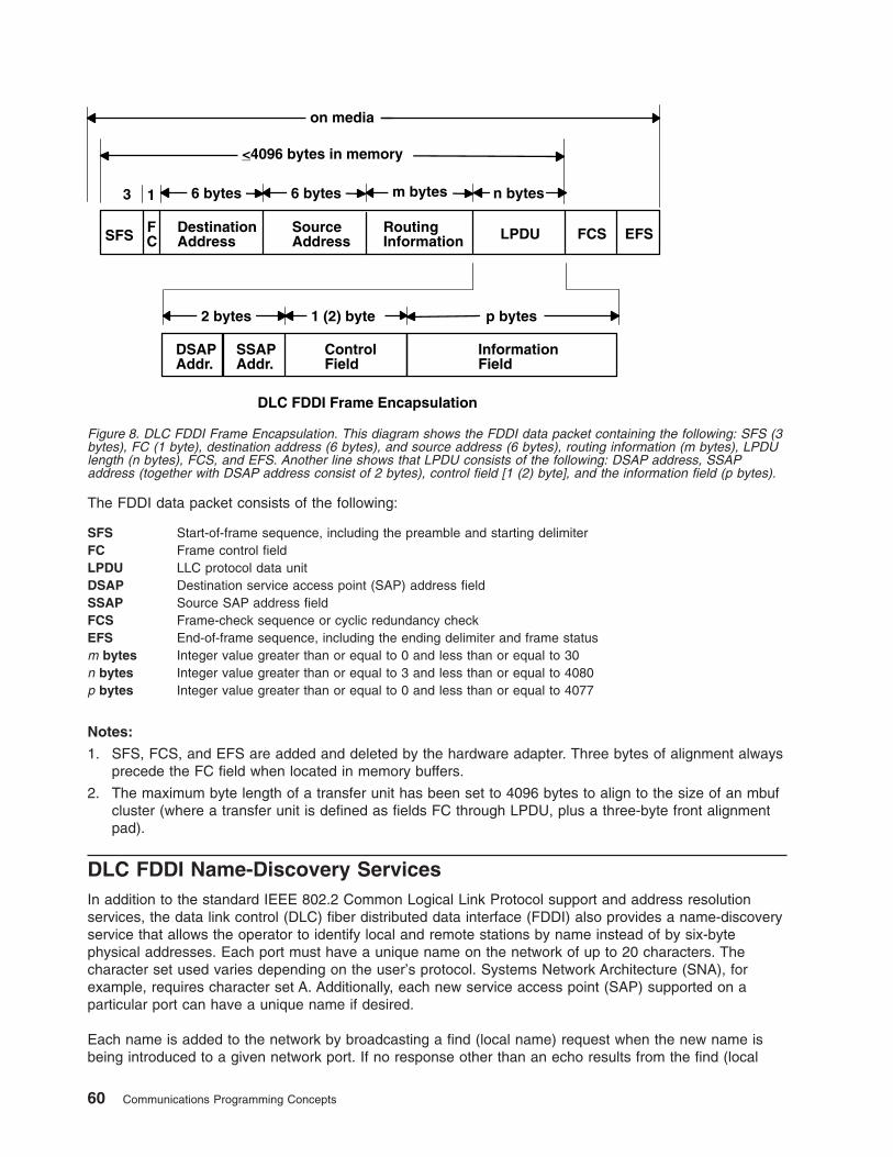
The FDDI data packet consists of the following:
SFS Start-of-frame sequence, including the preamble and starting delimiter
FC Frame control field
LPDU LLC protocol data unit
DSAP Destination service access point (SAP) address field
SSAP Source SAP address field
FCS Frame-check sequence or cyclic redundancy check
EFS End-of-frame sequence, including the ending delimiter and frame status
m bytes Integer value greater than or equal to 0 and less than or equal to 30
n bytes Integer value greater than or equal to 3 and less than or equal to 4080
p bytes Integer value greater than or equal to 0 and less than or equal to 4077
Notes:
1. SFS, FCS, and EFS are added and deleted by the hardware adapter. Three bytes of alignment always
precede the FC field when located in memory buffers.
2. The maximum byte length of a transfer unit has been set to 4096 bytes to align to the size of an mbuf
cluster (where a transfer unit is defined as fields FC through LPDU, plus a three-byte front alignment
pad).
DLC FDDI Name-Discovery Services
In addition to the standard IEEE 802.2 Common Logical Link Protocol support and address resolution
services, the data link control (DLC) fiber distributed data interface (FDDI) also provides a name-discovery
service that allows the operator to identify local and remote stations by name instead of by six-byte
physical addresses. Each port must have a unique name on the network of up to 20 characters. The
character set used varies depending on the user’s protocol. Systems Network Architecture (SNA), for
example, requires character set A. Additionally, each new service access point (SAP) supported on a
particular port can have a unique name if desired.
Each name is added to the network by broadcasting a find (local name) request when the new name is
being introduced to a given network port. If no response other than an echo results from the find (local
<4096 bytes in memory
DSAPAddr.
SSAPAddr.
ControlField
InformationField
2 bytes p bytes1 (2) byte
DestinationAddress
SourceAddress LPDU
6 bytes
FC
n bytes
DLC FDDI Frame Encapsulation
m bytes
on media
SFS
3 1
FCS EFSRoutingInformation
6 bytes
Figure 8. DLC FDDI Frame Encapsulation. This diagram shows the FDDI data packet containing the following: SFS (3
bytes), FC (1 byte), destination address (6 bytes), and source address (6 bytes), routing information (m bytes), LPDU
length (n bytes), FCS, and EFS. Another line shows that LPDU consists of the following: DSAP address, SSAP
address (together with DSAP address consist of 2 bytes), control field [1 (2) byte], and the information field (p bytes).
60 Communications Programming Concepts
name) request after sending it the number of times specified, the physical link is declared opened. The
name is then assigned to the local port and SAP. If another port on the network has already added the
name or is in the process of adding a name, a name-found response is sent to the station that issued the
find request, and the new attachment fails with a result code (DLC_NAME_IN_USE). The code indicates a
different name must be chosen. Calls are established by broadcasting a find (remote name) request to the
network and waiting for a response from the port with the specified name. Only those ports that have listen
attachments pending, receive colliding find requests, or are already attached to the requesting remote
station answer a find request.
LAN Find Data Format
Find Header
0-1 Byte length of the find packet including the length field
2-3 Key 0x0001
4-n Remaining control vectors
Target Name
0-1 Vector length = 0x000F to 0x0022
2-3 Key 0x0004
4-9 Name structure architecture ID:
4-5 Subvector length = 0x0006
6-7 Key 0x4011
8-9 Identifier = 0x8000 (locally administered)
10-m Object name:
10-11 Subvector length = 0x0005 to 0x000C
12-13 Key 0x4010
14-m Target name (1 to 20 bytes)
Source Name
0-1 Vector length = 0x000F to 0x0022
2-3 Key 0x000D
4-9 Name structure architecture ID:
4-5 Subvector Length = 0x0006
6-7 Key 0x4011
8-9 Identifier = 0x8000 (locally administered)
10-p Object name:
10-11 Subvector length = 0x0005 to 0x000C
12-13 Key 0x4010
14-p Source name (1 to 20 bytes)
Chapter 1. Data Link Control 61
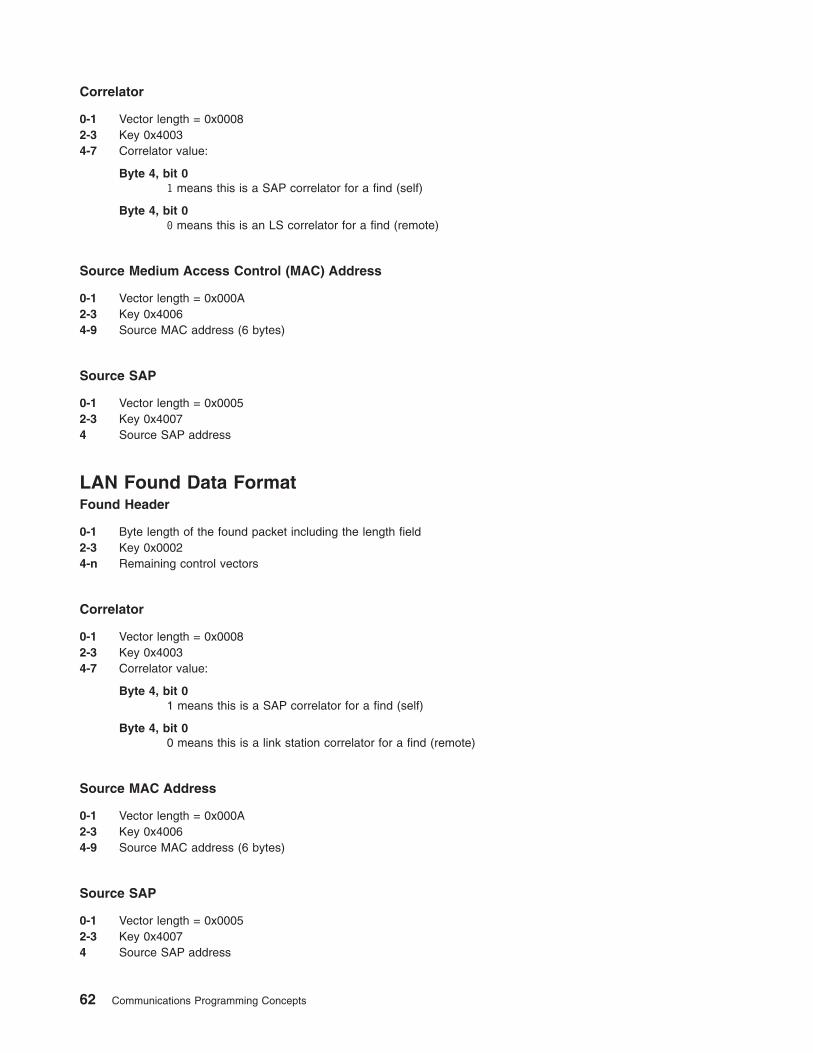
Correlator
0-1 Vector length = 0x0008
2-3 Key 0x4003
4-7 Correlator value:
Byte 4, bit 0
1 means this is a SAP correlator for a find (self)
Byte 4, bit 0
0 means this is an LS correlator for a find (remote)
Source Medium Access Control (MAC) Address
0-1 Vector length = 0x000A
2-3 Key 0x4006
4-9 Source MAC address (6 bytes)
Source SAP
0-1 Vector length = 0x0005
2-3 Key 0x4007
4 Source SAP address
LAN Found Data Format
Found Header
0-1 Byte length of the found packet including the length field
2-3 Key 0x0002
4-n Remaining control vectors
Correlator
0-1 Vector length = 0x0008
2-3 Key 0x4003
4-7 Correlator value:
Byte 4, bit 0
1 means this is a SAP correlator for a find (self)
Byte 4, bit 0
0 means this is a link station correlator for a find (remote)
Source MAC Address
0-1 Vector length = 0x000A
2-3 Key 0x4006
4-9 Source MAC address (6 bytes)
Source SAP
0-1 Vector length = 0x0005
2-3 Key 0x4007
4 Source SAP address
62 Communications Programming Concepts
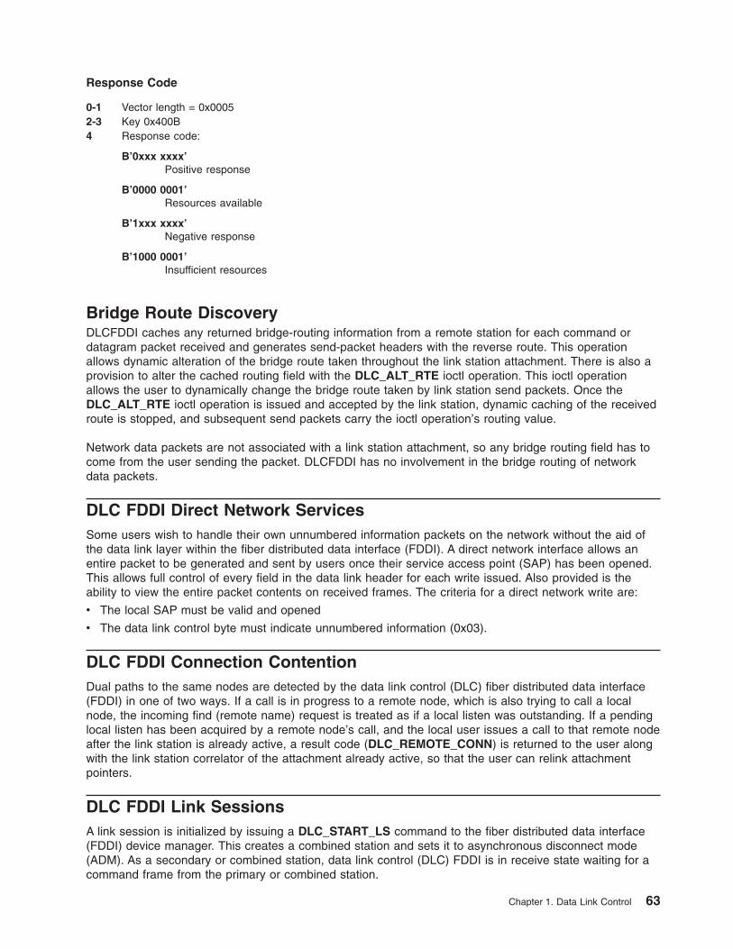
Response Code
0-1 Vector length = 0x0005
2-3 Key 0x400B
4 Response code:
B’0xxx xxxx’
Positive response
B’0000 0001’
Resources available
B’1xxx xxxx’
Negative response
B’1000 0001’
Insufficient resources
Bridge Route Discovery
DLCFDDI caches any returned bridge-routing information from a remote station for each command or
datagram packet received and generates send-packet headers with the reverse route. This operation
allows dynamic alteration of the bridge route taken throughout the link station attachment. There is also a
provision to alter the cached routing field with the DLC_ALT_RTE ioctl operation. This ioctl operation
allows the user to dynamically change the bridge route taken by link station send packets. Once the
DLC_ALT_RTE ioctl operation is issued and accepted by the link station, dynamic caching of the received
route is stopped, and subsequent send packets carry the ioctl operation’s routing value.
Network data packets are not associated with a link station attachment, so any bridge routing field has to
come from the user sending the packet. DLCFDDI has no involvement in the bridge routing of network
data packets.
DLC FDDI Direct Network Services
Some users wish to handle their own unnumbered information packets on the network without the aid of
the data link layer within the fiber distributed data interface (FDDI). A direct network interface allows an
entire packet to be generated and sent by users once their service access point (SAP) has been opened.
This allows full control of every field in the data link header for each write issued. Also provided is the
ability to view the entire packet contents on received frames. The criteria for a direct network write are:
v The local SAP must be valid and opened
v The data link control byte must indicate unnumbered information (0x03).
DLC FDDI Connection Contention
Dual paths to the same nodes are detected by the data link control (DLC) fiber distributed data interface
(FDDI) in one of two ways. If a call is in progress to a remote node, which is also trying to call a local
node, the incoming find (remote name) request is treated as if a local listen was outstanding. If a pending
local listen has been acquired by a remote node’s call, and the local user issues a call to that remote node
after the link station is already active, a result code (DLC_REMOTE_CONN) is returned to the user along
with the link station correlator of the attachment already active, so that the user can relink attachment
pointers.
DLC FDDI Link Sessions
A link session is initialized by issuing a DLC_START_LS command to the fiber distributed data interface
(FDDI) device manager. This creates a combined station and sets it to asynchronous disconnect mode
(ADM). As a secondary or combined station, data link control (DLC) FDDI is in receive state waiting for a
command frame from the primary or combined station.
Chapter 1. Data Link Control 63
The command frames currently accepted are:
SABME Set asynchronous balanced mode extended
XID Exchange identification
TEST Test link
UI Unnumbered information or datagram
DISC Disconnect
Any other command frame is ignored. Once a SABME is received, the contact sequence is complete and
the station is ready for normal data transfer and the following frames are also accepted as valid packet
types in this asynchronous balanced mode extended (ABME) mode:
I Information
RR Receive ready
RNR Receive not ready
REJ Reject
As a primary or combined station, DLC FDDI can perform ADM XID and ADM TEST exchanges, send
datagrams, or connect the remote into ABME. XID exchanges allow the primary or combined station to
send out its station-specific identification to the secondary or combined station and obtain a response.
Once an XID response is received, any attached information field is passed to the user for further action.
TEST exchanges allow the primary or combined station to send out an information buffer that is echoed by
the secondary or combined station to test the integrity of the link.
Initiation of the normal data exchange mode, ABME, causes the primary or combined station to send a
SABME to the secondary or combined station. Once sent successfully, the attachment is said to be
contacted and the user is notified. I-frames can now be sent and received between the linked stations.
Link Session Termination
The user or the remote station can end DLC FDDI in the following ways:
v The user can cause normal termination by issuing a DLC_HALT_LS command to the DLC FDDI device
manager. The DLC_HALT_LS command causes the primary or combined station to initiate a disconnect
(DISC) packet sequence.
v Receive inactivity can be optioned to cause termination. This is useful in detecting a loss of attachment
in the middle of a session.
v The remote station can cause termination by sending a DISC command packet as a primary or
combined station.
Note: Protocol violations and resource outages can cause abnormal termination.
DLC FDDI Programming Interfaces
The data link control (DLC) fiber distributed data interface (FDDI) conforms to generic data link control
(GDLC) guidelines except where noted below. Additional structures and definitions for DLC FDDI are found
in the /usr/include/sys/fdlextcb.h file.
The following entry points are supported by DLC FDDI:
Note: The dlc prefix is replaced with the fdl prefix for the DLC FDDI device manager.
fdlclose Fully compatible with the dlcclose GDLC interface.
fdlconfig Fully compatible with the dlcconfig GDLC interface. No initialization parameters are required.
64 Communications Programming Concepts
fdlmpx Fully compatible with the dlcmpx GDLC interface.
fdlopen Fully compatible with the dlcopen GDLC interface.
fdlread Compatible with the dlcread GDLC interface with the following conditions:
v The readx subroutines may have DLC FDDI data link header information prefixed to the
information field (I-field) being passed to the application. This is optional based on the readx
subroutine data link header length extension parameter in the gdl_io_ext structure.
v If this field is nonzero, DLC FDDI copies the data link header and the I-field to user space, and
sets the actual length of the data link header into the length field.
v If the field is 0, no data link header information is copied to user space. See the DLC FDDI
Frame Encapsulation (Figure 8 on page 60) figure for more details.
Kernel receive packet function handlers always have the DLC FDDI data link header information
within the communications memory buffer (mbuf), and can locate it by subtracting the length
passed (in the gdl_io_ext structure) from the data offset field of the mbuf structure.
fdlselect Fully compatible with the dlcselect GDLC interface.
fdlwrite Compatible with the dlcwrite GDLC interface, with the exception that network data can only be
written as an unnumbered information (UI) packet and must have the complete data link header
prefixed to the data. DLC FDDI verifies that the local (source) service access point (SAP) is
enabled and that the control byte is UI (0x03). See the DLC FDDI Frame Encapsulation figure
(Figure 8 on page 60) for more details.
fdlioctl Compatible with the dlcioctl GDLC interface. The following ioctl operations contain FDDI-specific
conditions on GDLC operations:
v “DLC_ENABLE_SAP”
v “DLC_START_LS” on page 66
v “DLC_ALTER” on page 67
v “DLC_ENTER_SHOLD” on page 67
v “DLC_EXIT_SHOLD” on page 67
v “DLC_ADD_GROUP” on page 68
v “DLC_ADD_FUNC_ADDR” on page 68
v “DLC_DEL_FUNC_ADDR” on page 68
v “DLC_DEL_GRP” on page 68
v “DLC_QUERY_SAP” on page 68
v “DLC_QUERY_LS” on page 68
v “IOCINFO” on page 68
The following sections describe these conditions.
DLC_ENABLE_SAP
The ioctl subroutine argument structure for enabling a SAP, dlc_esap_arg, has the following specifics:
v The grp_addr (group address) field contains the full six-byte group address with the individual control
bits, group control bits, universal control bits, and local control bits located in the most significant bit
positions of the first (leftmost) byte.
v The func_addr_mask (functional address mask) field is not supported.
v The max_ls (maximum link stations) field cannot exceed a value of 255.
v The following common SAP flags are not supported:
NTWK Indicates a teleprocessing network type.
LINK Indicates a teleprocessing link type.
PHYC Represents a physical network call (teleprocessing).
ANSW Indicates a teleprocessing autocall and autoanswer.
v Group SAPs are not supported, so the num_grp_saps (number of group SAPs) field must be set to 0.
Chapter 1. Data Link Control 65
v The laddr_name (local address or name) field and its associated length are only used for name
discovery when the common SAP flag ADDR is set to 0. When resolve procedures are used (the ADDR
flag set to 1), DLC FDDI obtains the local network address from the device handler and not from the
dlc_esap_arg structure.
v The local_sap (local service access point) field can be set to any value except the null SAP (0x00) or
the name-discovery SAP (0xFC). Also, the low-order bit must be set to 0 (B`nnnnnnn0’) to indicate an
individual address.
v No protocol-specific data area is required for DLC FDDI to enable an SAP.
DLC_START_LS
The ioctl subroutine argument structure for starting a link station, dlc_sls_arg, has the following specifics:
v The following common link station flags are not supported:
STAT Indicates a station type for SDLC.
NEGO Indicates a negotiable station type for SDLC.
v The raddr_name (remote address or name) field is used only for outgoing calls when the
DLC_SLS_LSVC common link station flag is active.
v The maxif (maximum I-field length) field can be set to any value greater than 0. The DLC FDDI device
manager adjusts this value to a maximum of 4077 bytes if set too large. See the DLC FDDI frame
encapsulation figure (“FDDI Data Packet” on page 59) for more details.
v The rcv_wind (receive window) field can be set to any value from 1 to 127, inclusive. The recommended
value is 127.
v The xmit_wind (transmit window) field can be set to any value from 1 to 127, inclusive. The
recommended value is 26.
v The rsap (remote SAP) field can be set to any value except the null SAP (0x00) or the name-discovery
SAP (0xFC). Also, the low-order bit must be set to 0 (B`nnnnnnn0’) to indicate an individual address.
v The max_repoll field can be set to any value from 1 to 255, inclusive. The recommended value is 8.
v The repoll_time field is defined in increments of 0.5 seconds and can be set to any value from 1 to 255,
inclusive. The recommended value is 2, giving a time-out duration of 1 to 1.5 seconds.
v The ack_time (acknowledgment time) field is defined in increments of 0.5 seconds, and can be set to
any value from 1 to 255, inclusive. The recommended value is 1, giving a time-out duration of 0.5 to 1
second.
v The inact_time (inactivity time) field is defined in increments of 1 second and can be set to any value
from 1 to 255, inclusive. The recommended value is 48, giving a time-out duration of 48 to 48.5
seconds.
v The force_time (force halt time) field is defined in increments of 1 second and can be set to any value
from 1 to 16383, inclusive. The recommended value is 120, giving a time-out duration of approximately
2 minutes.
v A protocol-specific data area must be appended to the generic start link station (LS) argument
(dlc_sls_arg). This structure provides DLC FDDI with additional protocol-specific configuration
parameters:
struct fdl_start_psd
{
uchar_t pkt_prty; /* ring access packet priority */
uchar_t dyna_wnd; /* dynamic window increment */
ushort_t reserved; /* currently not used */
};
The protocol-specific parameters are:
pkt_prty Specifies the ring-access priority that the user wishes to reserve on transmit packets. Values of 0 to 7
are supported, where 0 is the lowest priority and 7 is the highest priority.
66 Communications Programming Concepts
dyna_wnd Network congestion causes the local transmit window count to automatically drop to a value of 1. The
dynamic window increment specifies the number of consecutive sequenced packets that must be
acknowledged by the remote station before the local transmit window count can be increment. This
allows a gradual increase in network traffic after a period of congestion. This field can be set to any
value from 1 to 255; the recommended value is 1.
DLC_ALTER
The ioctl subroutine argument structure for altering a link station, dlc_alter_arg, has the following
specifics:
v The following common alter flags are not supported:
SM1, SM2 Sets SDLC control mode.
v A protocol-specific data area must be appended to the generic alter link station argument structure
(dlc_alter_arg). This structure provides DLC FDDI with additional protocol-specific alter parameters.
#define FDL_ALTER_PRTY 0x80000000 /* alter packet priority */
#define FDL_ALTER_DYNA 0x40000000 /* alter dynamic window incr*/
struct fdl_alter_psd
{
ulong_t flags; /* specific alter flags */
uchar_t pkt_prty; /* ring access packet priority value */
uchar_t dyna_wnd; /* dynamic window increment value */
ushort_t reserved; /* currently not used */
};
#define FDL_ALTER_PRTY 0x80000000 /* alter packet priority */
#define FDL_ALTER_DYNA 0x40000000 /* alter dynamic window incr*/
struct fdl_alter_psd
{
__ulong32_t flags; /* specific alter flags */
uchar_t pkt_prty; /* ring access packet priority value */
uchar_t dyna_wnd; /* dynamic window increment value */
ushort_t reserved; /* currently not used */
};
v Specific alter flags include:
FDL_ALTER_PRTY Specifies alter priority. If set to 1, the pkt_prty value field replaces the current priority
value being used by the link station. The link station must be started for this alter
command to be valid.
FDL_ALTER_DYNA Specifies alter dynamic window. If set to 1, the dyna_wnd value field replaces the current
dynamic window value being used by the link station. The link station must be started for
this alter command to be valid.
The protocol-specific parameters are:
pkt_prty Specifies the new priority reservation value for transmit packets.
dyna_wnd Specifies the new dynamic window value to control network congestion.
DLC_ENTER_SHOLD
The enter_short_hold option is not supported.
DLC_EXIT_SHOLD
The exit_short_hold option is not supported.
Chapter 1. Data Link Control 67
DLC_ADD_GROUP
The add_group, or multicast address, option is supported by DLC FDDI as a six-byte value as described
above in DLC_ENABLE_SAP (group address).
The grp_addr (group address) field for FDDI contains the full six-byte group address with the
individual/group and universal/local control bits located in the most significant bit positions of the first
(leftmost) byte.
DLC_ADD_FUNC_ADDR
The add_functional_address option is not supported.
DLC_DEL_FUNC_ADDR
The delete_functional_address option is not supported.
DLC_DEL_GRP
The delete group or multicast option is supported by the DLC FDDI device manager. The address being
removed must match an address that was added with a DLC_ENABLE_SAP or DLC_ADD_GRP ioctl
operation.
DLC_QUERY_SAP
The device driver-dependent data returned from DLC FDDI for this ioctl operation is the fddi_ndd_stats_t
structure defined in the /usr/include/sys/cdli_fddiuser.h file.
DLC_QUERY_LS
There is no protocol-specific data area supported by DLC FDDI for this ioctl operation.
IOCINFO
The ioctype variable returned is defined as a DD_DLC definition and the subtype returned is
DS_DLCFDDI.
Asynchronous Function Calls
DLC FDDI is fully compatible with the GDLC interface concerning asynchronous function calls to the kernel
mode user.
68 Communications Programming Concepts
Chapter 2. Data Link Provider Interface Implementation
The Data Link Provider Interface (DLPI) implementation of the operating system is designed to follow
AT&T’s ″UNIX® International OSI Work Group Data Link Provider Interface″ Version 2 (DRAFT)
specification. You can obtain a copy electronically if you have Internet access. For information about
obtaining the DLPI specification, see “Obtaining Copies of the DLPI Specifications” on page 76.
It is assumed that you are familiar with the DLPI Version 2 specification published by UNIX International,
RFC1042, and the various IEEE 802.x documents.
Note: In the text below, the term dlpi refers to the driver, while DLPI refers to the specification.
The dlpi driver is implemented as a style 2 provider and supports both the connectionless and
connection-oriented modes of communication. For a list of the primitives supported by the dlpi driver, see
“DLPI Primitives” on page 74.
Primitive Implementation Specifics
Information pertinent to specific primitives implemented in the dlpi driver is documented in the man page
for that primitive.
Packet Format Registration Specifics
The dlpi driver supports generic Common Data Link Interface (CDLI) network interfaces by allowing the
user to specify the particular packet format necessary for the transmission media over which the stream is
created. Using the M_IOCTL or M_CTL streams message, the user can specify the packet format. If no
packet format is specified, the default is NS_PROTO.
The DLPI user specifies the packet format through the STREAMS I_STR ioctl. The DLPI user is allowed
one packet format specification per stream. This packet format must be specified after the attach and
before the bind. Otherwise, an error is generated.
The packet formats defined in /usr/include/sys/cdli.h follow:
NS_PROTO Remove all link-level headers. Sub-Network Access Protocol (SNAP) is not used.
NS_PROTO_SNAP Remove all link-level headers including SNAP.
NS_INCLUDE_LLC Leave LLC headers in place.
NS_INCLUDE_MAC Do not remove any headers.
The packet formats defined in the /usr/include/sys/dlpi_aix.h file are:
NS_PROTO_DL_COMPAT Use the AIX 3.2.5 DLPI address format.
NS_PROTO_DL_DONTCARE No addresses present in DL_UNITDATA_IND. For the
DL_UNITDATA_IND primitive, DLPI provides the header information in
the dl_unitdata_ind_t structure.
All packet formats except NS_INCLUDE_MAC accept downstream addresses in the following form:
mac_addr.dsap[.snap].
© Copyright IBM Corp. 1994, 2005 69
Individually, packet formats have the following requirements:
NS_PROTO or NS_PROTO_SNAP Medium access control (MAC) and logical link control (LLC) are included in
the DLPI header, and the data portion of the message contains only data. The
NS_PROTO header does not include SNAP; the NS_PROTO_SNAP header
does. Both packet formats present destination addresses as mac_addr and
source addresses as mac_addr.ssap.dsap.ctrl[.snap].
For the DL_UNITDATA_REQ primitive, the DLPI user must provide the
destination address and an optional destination service access point (DSAP)
in the DLPI header. If the DLPI user does not specify the DSAP, the DSAP
specified at bind time is used.
NS_PROTO_DONTCARE The dlpi driver places no addresses in the upstream DL_UNITDATA_IND.
Addresses are still required on the DL_UNITDATA_REQ.
NS_PROTO_DL_COMPAT The dlpi driver uses the address format used in the AIX 3.2.5 dlpi driver, which
is identical both upstream and downstream. The source and destination
addresses are presented as mac_addr.dsap[.snap].
NS_INCLUDE_LLC The DLPI header contains only the destination and source addresses. Only
the LLC is placed in the M_DATA portion of the DL_UNITDATA_IND
message. Both the source and destination addresses are presented as
mac_addr.
For the DL_UNITDATA_REQ primitive, the DLPI user must provide the
destination address and an optional DSAP in the DLPI header. If the DLPI
user does not specify the DSAP, the DSAP specified at bind time is used.
NS_INCLUDE_MAC The MAC and LLC are both placed in the data portion of the message. Thus,
the DLPI user must have knowledge of the MAC header and LLC architecture
for a specific interface to retrieve the MAC header and LLC from the data
portion of the message. This format sets the stream to raw mode, which does
not process incoming or outgoing messages.
For the DL_UNITDATA_REQ primitive, the DLPI user must provide the
destination address and an optional DSAP in the DLPI header. If the DLPI
user does not specify the DSAP, the DSAP specified at bind time is used.
Downstream messages do not require the DL_UNITDATA_REQ header and
must be received as M_DATA messages. Downstream messages must
contain a completed MAC header, which will be copied to the medium without
further translation.
Address Resolution Routine Registration Specifics
The dlpi driver can support all generic interface types. DLPI is implemented to allow the user to specify
address resolution routines for input and output using the STREAMS I_STR ioctl or to rely on the system
default routines. The operating system provides default address resolution routines (stored in the
/usr/include/sys/ndd.h file) that are interface specific.
The default input address resolution routine is as follows:
ndd->ndd_demuxer->nd_address_input
The dlpi driver calls the input address resolution routine with a pointer to the MAC header (and, optionally,
the LLC header) and a pointer to a memory buffer (mbuf) structure containing data. The actual contents of
the data area depend on which type of packet format was specified. (See “Packet Format Registration
Specifics” on page 69.)
The default output address resolution routine is:
ndd->ndd_demuxer->nd_address_resolve
70 Communications Programming Concepts
The dlpi driver calls the output address resolution routine with a pointer to an output_bundle structure
(described in /usr/include/net/nd_lan.h), an mbuf structure, and an ndd structure. The driver assigns the
destination address to key_to_find and copies the pkt_format and bind time llc into helpers. If the user
has provided a different DSAP than what was set at bind time, the driver also copies the DSAP values into
helpers.The output resolution routine completes the MAC header and calls the ndd_output subroutine.
If you choose to specify an input or output address resolution routine or both, use the following sample
code:
noinres(int fd) {
return istr(fd, DL_INPUT_RESOLVE, 0);
}
ioctl Specifics
The dlpi driver supports the following ioctl operations:
v DL_ROUTE
v DL_TUNE_LLC
v DL_ZERO_STATS
v DL_SET_REMADDR
These commands and their associated data structures are described in the /usr/include/sys/dlpi_aix.h
header file.
Note: The ioctl commands that require an argument longer than one long word, or that specify a pointer
for either reading or writing, must use the I_STR format, as in the following example:
int
istr(int fd, int cmd, char *data, int len) {
struct strioctl ic;
ic.cmd = cmd;
ic.timout = -1;
ic.dp = data;
ic.dp = data;
ic.len = len;
return ioctl(fd, I_STR, &ic);
}
DL_ROUTE Disables the source routing on the current stream, queries the “Dynamic Route
Discovery” on page 73 for a source route, or statically assigns a source route to this
stream. It is only accepted when the stream is idle (DL_IDLE).
v If the argument length is 0, no source route is used on outgoing frames.
v If the argument length is equal to the length of the MAC address for the current
medium (for example, 6 for most 802.x providers), the DRD algorithm is used to obtain
the source route for the address specified in the argument. The MAC address is
replaced with the source route on return from the ioctl.
v Otherwise, the argument is assumed to contain an address of the form
mac_addr.source_route, and the source_route portion is used as the source route for
this stream in all communications.
As an example, the following code can be used to discover the source route for an
arbitrary address:
char *
getroute(int fd, char *addr, int len) {
static char route[MAXROUTE_LEN];
bcopy(addr, route, len);
if (istr(fd, DL_ROUTE, route, len))
return 0;
return route;
}
Chapter 2. Data Link Provider Interface Implementation 71
DL_TUNE_LLC Allows the DLS user to alter the default LLC tunable parameters. The argument must
point to an llctune_t data structure.
The flags field is examined to determine which, if any, parameters should be changed.
Each bit in the flags field corresponds to a similarly named field in the llctune_t; if the bit
is set, the corresponding parameter is set to the value in llctune_t. Only the current
stream is affected, and changes are discarded when the stream is closed.
If the F_LLC_SET flag is set and the user has root authority, the altered parameters are
saved as the new default parameters for all new streams.
This command returns as its argument an update of the current tunable parameters.
For example, to double the t1 value, the following code might be used:
int
more_t1(int fd) {
llctune_t t;
t.flags = 0;
if (istr(fd, DL_TUNE_LLC, &t, sizeof(t)))
return -1;
t.flags = F_LLC_T1;
t.t1 *= 2;
return istr(fd, DL_TUNE_LLC, &t, sizeof(t));
}
To query the tunables, issue DL_TUNE_LLC with the flags field set to zero. This will alter
no parameters and return the current tunable values.
DL_ZERO_STATS Resets the statistics counters to zero. The driver maintains two independent sets of
statistics, one for each stream (local), and another that is the cumulative statistics for all
streams (global).
This command accepts a simple boolean argument. If the argument is True (nonzero),
the global statistics are zeroed. Otherwise, only the current stream’s statistics are zeroed.
For example, to zero the statistics counters on the current stream, the following code
might be used:
int
zero_stats(int fd) {
return ioctl(fd, DL_ZERO_STATS, 0);
}
DL_SET_REMADDR Allows XID/TEST exchange on connection-oriented streams while still in the DL_IDLE
state.
The dlpi driver uses both the source (remote) address and the dl_sap to determine where
to route incoming messages for connection-oriented streams. The remote address is
ordinarily specified in DL_CONNECT_REQ. If the DLS user needs to exchange XID or
TEST messages before connecting to the remote station, DL_SET_REMADDR must be
used.
Note: Note that this command is not necessary if XID and TEST messages are to be
exchanged only when the state is DL_DATAXFER.
The argument to this command is the remote MAC address. One possible code fragment
might be:
int
setaddr(int fd, char *addr, int len) {
return istr(fd, DL_SET_REMADDR, addr, len);
}
72 Communications Programming Concepts
Dynamic Route Discovery
Dynamic Route Discovery (DRD) is an algorithm used to automatically discover the proper source route
that reaches a remote station on either a token ring or a Fiber Distributed Data Interface (FDDI) network. It
relieves the DLS user from discovering and maintaining source routes. The algorithm implements the
spanning tree, as recommended by 802.5.
When the DLS user issues a transmission request (for example, DL_CONNECT_REQ or
DL_UNITDATA_REQ) on a medium supporting source routing, the DRD algorithm consults a local cache
of source routes. If there is a hit, the cached source route is used immediately. Otherwise, the DRD
queues the transmission request and starts the discovery algorithm. If the algorithm finds a source route,
the new route is cached, and the queued requests are transmitted using this new route. If the algorithm
times out with no replies (approximately 10 seconds), the queued requests are rejected.
The cache is periodically flushed of stale entries. An entry becomes stale after 5 minutes of no new
requests.
Note: After a connection is established, the source route discovered during the connection setup is used
to the exclusion of the DRD. This has two effects:
v If the source route changes during a connection, the connection continues to use the original
source route.
v If the original source route becomes invalid, the connection breaks, and no rediscovery is
attempted until a new connection is started.
DRD Configuration
The DRD is selectable on a per-media basis when the dlpi driver is first loaded into the kernel. By default,
the DRD is disabled for all media types. It can be enabled by appending the string ″,r″ (uses routing) to
the argument field in /etc/dlpi.conf. Once selected, it is used by all physical points of attachment (PPAs)
for that media type. The following example configurations both show token ring and FDDI configured, first
in a default configuration and then with DRD enabled.
Default configuration:
d+ dlpi tr /dev/dlpi/tr
d+ dlpi fi /dev/dlpi/fi
DRD-enabled configuration:
d+ dlpi tr,r /dev/dlpi/tr
d+ dlpi fi,r /dev/dlpi/fi
Connectionless Mode Only DLPI Driver versus
Connectionless/Connection-Oriented DLPI Driver
Notes:
1. For binary compatibility purposes, there are no new statistics added for the connection-oriented
functions. Statistics for the connection-oriented functions will be provided in a future release of the
operating system.
2. For binary compatibility purposes, a DL_UNITDATA_IND header is provided in the messages for
promiscuous mode and raw mode. Be aware that this header will be removed in a future release of the
operating system.
The following sample code fragment works with the 4.1 and later versions of DLPI:
if (raw_mode) {
if (mp->b_datap->db_type == M_PROTO) {
union DL_primitives *p;
Chapter 2. Data Link Provider Interface Implementation 73
p = (union DL_primitives *)mp->b_rptr;
if (p->dl_primitive == DL_UNITDATA_IND) {
mblk_t *mpl = mp->b_cont;
freeb(mp);
mp = mpl;
}
}
}
The above code fragment discards the DL_UNITDATA_IND header. For compatibility with future
releases, it is recommended that you parse the frame yourself. The MAC and LLC headers are
presented in the M_DATA message for both promiscuous mode and raw mode.
Raw mode currently accepts, but does not require, a DL_UNITDATA_REQ. In a future release of the
operating system, raw mode will not accept a DL_UNITDATA_REQ; only M_DATA will be accepted.
The dlpi driver supports the 802.2 connection-oriented service over the CDLI-based media 802.3, token
ring, and FDDI. Other CDLI-based media can be supported provided the media implementation follows the
IEEE 802.x recommendations.
The DL_BIND_REQ primitive accepts values for some fields (refer to the DL_BIND_REQ primitive in AIX
5L Version 5.3 Technical Reference: Communications Volume 1).
The DL_OUTPUT_RESOLVE and DL_INPUT_RESOLVE ioctl commands replace the default address
resolution routines for the current stream. They are no longer accepted from user space; the message
type must be M_CTL (not M_IOCTL), and they are only accepted before the stream is bound.
DL_INPUT_RESOLVE is accepted as an M_IOCTL message only if its argument is zero; this allows the
user to disable input address resolution. Output address resolution cannot be disabled—use the raw mode
if transparent access to the medium is required.
The DL_PKT_FORMAT ioctl command now recognizes and handles the following packet formats:
NS_PROTO, NS_PROTO_SNAP, NS_PROTO_DL_DONTCARE, NS_PROTO_DL_COMPAT,
NS_INCLUDE_LLC, and NS_INCLUDE_MAC.
New ioctl commands are now supported: DL_ROUTE, DL_TUNE_LLC, DL_ZERO_STATS, and
DL_SET_REMADDR. Refer to “ioctl Specifics” on page 71.
DLPI Primitives
The following primitives are supported by DLPI:
v DL_ATTACH_REQ
v DL_BIND_ACK
v DL_BIND_REQ
v DL_DETACH_REQ
v DL_DISABMULTI_REQ
v DL_ENABMULTI_REQ
v DL_ERROR_ACK
v DL_GET_STATISTICS_REQ
v DL_GET_STATISTICS_ACK
v DL_INFO_ACK
v DL_INFO_REQ
v DL_OK_ACK
v DL_PHYS_ADDR_REQ
v DL_PHYS_ADDR_ACK
v DL_PROMISCOFF_REQ
74 Communications Programming Concepts
v DL_PROMISCON_REQ
v DL_SUBS_BIND_ACK
v DL_SUBS_BIND_REQ
v DL_SUBS_UNBIND_REQ
v DL_TEST_CON
v DL_TEST_IND
v DL_TEST_REQ
v DL_TEST_RES
v DL_UDERROR_IND
v DL_UNBIND_REQ
v DL_UNITDATA_IND
v DL_UNITDATA_REQ
v DL_XID_CON
v DL_XID_IND
v DL_XID_REQ
v DL_XID_RES
The following connection-oriented service primitives are supported:
v DL_CONNECT_REQ
v DL_CONNECT_IND
v DL_CONNECT_RES
v DL_CONNECT_CON
v DL_TOKEN_REQ
v DL_TOKEN_ACK
v DL_DATA_REQ
v DL_DATA_IND
v DL_DISCONNECT_REQ
v DL_DISCONNECT_IND
v DL_RESET_REQ
v DL_RESET_IND
v DL_RESET_RES
v DL_RESET_CON
The following primitives are not supported:
v DL_UDQOS_REQ
v DL_SET_PHYS_ADDR_REQ
The following acknowledged connectionless-mode primitives are not supported:
v DL_DATA_ACK_REQ
v DL_DATA_ACK_IND
v DL_DATA_ACK_STATUS_IND
v DL_REPLY_REQ
v DL_REPLY_IND
v DL_REPLY_STATUS_IND
v DL_REPLY_UPDATE_REQ
v DL_REPLY_UPDATE_STATUS_IND
Chapter 2. Data Link Provider Interface Implementation 75
Note: If any unsupported primitive is issued to the provider, the provider will return the
DL_ERROR_ACK primitive with the DL_NOTSUPPORTED error code.
Obtaining Copies of the DLPI Specifications
You can obtain copies of the Data Link Provider Interface (DLPI) specifications electronically using File
Transfer Protocol (FTP) commands. A postscript version of the DLPI specifications may be retrieved
electronically by anonymous ftp from any of the following list of Internet hosts.
Hosts IP Address Pathname
liasun3.epfl.ch 128.178.155.12 /pub/sun/dlpi
marsh.cs.curtin.edu.au 134.7.1.1 /pub/netman/dlpi
ftp.eu.net 192.16.202.2 /network/netman/dlpi
opcom.sun.ca 142.77.1.61 /pub/drivers/dlpi
ftp.cac.psu.edu 128.118.2.23 /pub/unix/netman/dlpi
To retrieve the postscript DLPI specifications through anonymous ftp, use the following example:
ftp ftp.eu.net
Connected to eunet.EU.net.
220-
220-Welcome to the central EUnet Archive,
220-
220 eunet.EU.net FTP server (Version wu-2.4(2) Jul 09 1993) ready.
Name (ftp.eu.net:jhaug):anonymous
ftp> user anonymous
331 Guest login ok, send your complete e-mail address as password.
Password:
ftp> cd /network/netman/dlpi
250 CWD command successful.
ftp> bin
200 Type set to I.
ftp> get dlpi.ps.Z
200 PORT command successful.
150 Opening BINARY mode data connection for dlpi.ps.Z (479345 bytes).
226 Transfer complete.
1476915 bytes received in 39.12 seconds (11.97 Kbyte/s)
ftp> quit
221 Goodbye.
There is no guarantee that a public Internet server will always be available. If the above public Internet
server host is not available, you might try using one of the Internet archive server listing services, such as
Archie, to search for a public server that has the DLPI specifications.
76 Communications Programming Concepts
Chapter 3. New Database Manager
The New Database Manager (NDBM) subroutines maintain key and content pairs in a database. The
NDBM subroutines handle large databases and access keyed items in one or two file system accesses.
Keyed items are consecutive characters, taken from a data record, that identify the record and establish its
order with respect to other records.
NDBM databases are stored in two files. One file is a directory containing a bit map and it has the
extension .dir. The second file contains only data and has the extension .pag.
For example, Network Information Service (NIS) maps maintain database information in NDBM format. NIS
maps are created using the makedbm command. The makedbm command converts input into NDBM
format files. An NIS map consists of two files: map.key.pag and map.key.dir. The file with the .dir
extension serves as an index for the .pag files. The file with the .pag extension contains the key and value
pairs.
Note: The NDBM library replaces the earlier Database Manager (DBM) library, which managed a single
database.
Using NDBM Subroutines
To access a database, issue the dbm_open subroutine. The dbm_open subroutine opens or creates the
file.dir and file.pag files, depending on the flags parameter. To close a database, issue the dbm_close
subroutine. Close one database before opening another database.
Other NDBM subroutines include the following:
dbm_delete Deletes a key and its associated contents.
dbm_fetch Accesses data stored under a key.
dbm_firstkey Returns the first key in the database.
dbm_nextkey Returns the next key in the database.
dbm_store Stores data under a key.
Diagnosing NDBM Problems
A return value of 0 indicates no error. Subroutines that return a negative value indicate an error has
occurred. A positive integer return indicates the status of the return. For example, if the dbm_store
subroutine, issued with an insert flag, finds an existing entry with the same key, it returns a 1.
The dbm_fetch, dbm_firstkey, and dbm_nextkey subroutines return a datum structure containing the
value returned for the specified key. If the subroutine is unsuccessful, a null value is indicated in the dptr
field of the datum structure.
List of NDBM and DBM Programming References
This list includes both New Database Manager (NDBM) subroutines and their equivalent Database
Manager (DBM) subroutines.
NDBM Subroutines
dbm_close Closes a database.
dbm_delete Deletes a key and its associated contents.
dbm_fetch Accesses data stored under a key.
© Copyright IBM Corp. 1994, 2005 77
dbm_firstkey Returns the first key in the database.
dbm_nextkey Returns the next key in the database.
dbm_open Opens a database for access.
dbm_store Stores data under a key.
DBM Subroutines
dbmclose Closes a database.
dbminit Opens a database.
delete Deletes a key and its associated contents.
fetch Accesses the data stored under a key.
firstkey Returns the first key that matches the specification.
nextkey Returns the next key in the database.
store Stores data under a key.
78 Communications Programming Concepts
Chapter 4. eXternal Data Representation
The eXternal Data Representation (XDR) is a standard for the description and encoding of data. XDR uses
a language to describe data formats, but the language is used only for describing data and is not a
programming language. Protocols such as Remote Procedure Call (RPC) and the Network File System
(NFS) use XDR to describe their data formats.
This chapter discusses the following topics:
v “eXternal Data Representation Overview for Programming”
v “XDR Subroutine Format” on page 81
v “XDR Library” on page 81
v “XDR Language Specification” on page 82
v “XDR Data Types” on page 84
v “List of XDR Programming References” on page 94
v “XDR Library Filter Primitives” on page 95
v “XDR Non-Filter Primitives” on page 98
v “Passing Linked Lists Using XDR Example” on page 100
v “Using an XDR Data Description Example” on page 102
v “Showing the Justification for Using XDR Example” on page 103
v “Using XDR Example” on page 105
v “Using XDR Array Examples” on page 106
v “Using an XDR Discriminated Union Example” on page 107
v “Showing the Use of Pointers in XDR Example” on page 108
eXternal Data Representation Overview for Programming
This overview provides the following information about programming XDR:
v “XDR Subroutine Format” on page 81
v “XDR Library” on page 81
v “XDR Language Specification” on page 82
v “XDR Data Types” on page 84
v “XDR Library Filter Primitives” on page 95
v “XDR Non-Filter Primitives” on page 98
v “List of XDR Programming References” on page 94
XDR not only solves data portability problems, it also permits the reading and writing of arbitrary C
language constructs in a consistent and well-documented manner. Therefore, it makes sense to use the
XDR library routines even when the data is not shared among machines on a network.
The XDR standard does not depend on machine languages, manufacturers, operating systems, or
architectures. This condition enables networked computers to share data regardless of the machine on
which the data is produced or consumed. The XDR language permits transfer of data between different
computer architectures and has been used to communicate data between such diverse machines as the
VAX, IBM®, and Cray.
Remote Procedure Call (RPC) uses XDR to establish uniform representations for data types in order to
transfer message data between machines. For basic data types, such as integers and strings, XDR
provides filter primitives that serialize, or translate, information from the local host’s representation to
XDR’s representation. Likewise, XDR filter primitives deserialize XDR’s data representation to the local
© Copyright IBM Corp. 1994, 2005 79

host’s data representation. XDR constructor primitives allow the use of the basic data types to create more
complex data types such as arrays and discriminated unions.
The XDR routines that are called directly by remote procedure call routines can be found in “List of XDR
Programming References” on page 94.
A Canonical Standard
The XDR approach to standardizing data representations is canonical. That is, XDR defines
representations for a single byte (most significant bit first), a single floating-point representation (IEEE),
and so on. Any program running on any machine can use XDR to create portable data by translating its
local representation to the XDR standards. Similarly, any program running on any machine can read
portable data by translating the XDR standard representations to its local equivalents. The canonical
standard completely decouples programs that create or send portable data from those that use or receive
portable data.
The advent of a new machine or new language has no effect upon the community of existing portable data
creators and users. A new machine can be programmed to convert both the standard representations and
its local representations regardless of the local representations of other machines. Conversely, the local
representations of the new machine are also irrelevant to existing programs running on other machines.
These existing programs can immediately read portable data produced by the new machine, because such
data conforms to canonical standards.
Strong precedents exist for XDR’s canonical approach. All protocols below layer five of the ISO model,
including Transmission Control Protocol (TCP), Internet Protocol (IP), User Datagram Protocol (UDP), and
Ethernet, are canonical protocols. The advantage of any canonical approach is simplicity. XDR fits into the
ISO presentation layer and is roughly analogous in purpose to X.409, ISO Abstract Syntax Notation. The
major difference here is that XDR uses implicit typing, while X.409 uses explicit typing. With XDR, a single
set of conversion routines need only be written once.
The time spent converting to and from a canonical representation is insignificant, especially in networking
applications. When preparing a data structure for transfer, traversing the elements of the structure requires
more time than converting the data. In networking applications, additional time is required to move the
data down through the sender’s protocol layers, across the network, and up through the receiver’s protocol
layers. Every machine must traverse and copy data structures, regardless of whether conversion is
required.
Basic Block Size
The XDR language is based on the assumption that bytes (eight bits of data or an octet) can be ported to
and encoded on media that preserve the meaning of the bytes across the hardware boundaries of data.
XDR does not represent bit fields or bit maps. It represents data in blocks of multiples of four bytes (32
bits). The bytes are numbered from 0 to the value of n - 1, where the value (n mod 4) equals 0. They
are read from or written to a byte stream in order, such that byte m precedes byte m + 1.
Bytes are ported and encoded from low order to high order in local area networks. Representing data in
standardized formats resolves situations that occur when different byte-ordering formats exist on
networked machines. This also enables machines with different structure-alignment algorithms to
communicate with each other.
See the A Block figure (Figure 9 on page 81) for a representation of a block.
80 Communications Programming Concepts
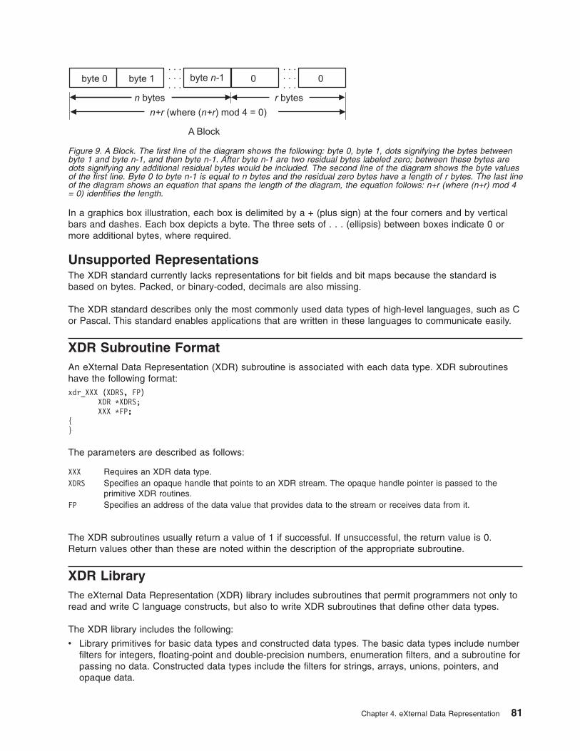
In a graphics box illustration, each box is delimited by a + (plus sign) at the four corners and by vertical
bars and dashes. Each box depicts a byte. The three sets of . . . (ellipsis) between boxes indicate 0 or
more additional bytes, where required.
Unsupported Representations
The XDR standard currently lacks representations for bit fields and bit maps because the standard is
based on bytes. Packed, or binary-coded, decimals are also missing.
The XDR standard describes only the most commonly used data types of high-level languages, such as C
or Pascal. This standard enables applications that are written in these languages to communicate easily.
XDR Subroutine Format
An eXternal Data Representation (XDR) subroutine is associated with each data type. XDR subroutines
have the following format:
xdr_XXX (XDRS, FP)
XDR *XDRS;
XXX *FP;
{
}
The parameters are described as follows:
XXX Requires an XDR data type.
XDRS Specifies an opaque handle that points to an XDR stream. The opaque handle pointer is passed to the
primitive XDR routines.
FP Specifies an address of the data value that provides data to the stream or receives data from it.
The XDR subroutines usually return a value of 1 if successful. If unsuccessful, the return value is 0.
Return values other than these are noted within the description of the appropriate subroutine.
XDR Library
The eXternal Data Representation (XDR) library includes subroutines that permit programmers not only to
read and write C language constructs, but also to write XDR subroutines that define other data types.
The XDR library includes the following:
v Library primitives for basic data types and constructed data types. The basic data types include number
filters for integers, floating-point and double-precision numbers, enumeration filters, and a subroutine for
passing no data. Constructed data types include the filters for strings, arrays, unions, pointers, and
opaque data.
Figure 9. A Block. The first line of the diagram shows the following: byte 0, byte 1, dots signifying the bytes between
byte 1 and byte n-1, and then byte n-1. After byte n-1 are two residual bytes labeled zero; between these bytes are
dots signifying any additional residual bytes would be included. The second line of the diagram shows the byte values
of the first line. Byte 0 to byte n-1 is equal to n bytes and the residual zero bytes have a length of r bytes. The last line
of the diagram shows an equation that spans the length of the diagram, the equation follows: n+r (where (n+r) mod 4
= 0) identifies the length.
Chapter 4. eXternal Data Representation 81
v Data stream creation routines that call streams for serializing and deserializing data to or from standard
I/O file streams, Transmission Control Protocol (TCP), Internet Protocol (IP) connections, and memory.
v Subroutines for the implementation of new XDR streams.
v Subroutines for passing linked lists.
See “Showing the Justification for Using XDR Example” on page 103.
XDR with RPC
The XDR subroutines and macros may be called explicitly or by a Remote Procedure Call (RPC)
subroutine. When using XDR with RPC, clients do not create data streams. Instead, the RPC interface
creates the streams. The RPC interface passes the information about a data stream as opaque data in the
form of handles. This opaque data handle is referred to in subroutines as the xdrs parameter.
Programmers who use C language programs with XDR subroutines must include the rpc/xdr.h file, which
contains the necessary XDR interfaces.
XDR Operation Directions
The XDR subroutines are not dependent on direction. The operation direction represented by xdrs->xop
can have an XDR_ENCODE, XDR_DECODE, or XDR_FREE value. These operation values are handled
internally by the XDR subroutines, which means the same XDR subroutine can be called to serialize or
deserialize data. To achieve this independence, XDR passes the address of the object instead of passing
the object itself.
XDR Language Specification
The eXternal Data Representation (XDR) language specification uses an extended Backus Naur form
notation for describing the XDR language. The following is a brief description of the notation:
v The following characters are special characters:
| A vertical bar separates alternative items.
( ) Parentheses enclose items that are grouped together.
[ ] Brackets enclose optional items.
, A comma separates more than one variable.
* An asterisk following an item means 0 or more occurrences of the item.
v Terminal symbols are strings of special and nonspecial characters surrounded by ″ ″ (double quotation
marks).
v Nonterminal symbols are strings of nonspecial characters.
The following specification illustrates the XDR notation:
"a" "very" ("," "very")* ["cold" "and"] "rainy" ("day" | "night")
An infinite number of strings match this pattern, including the following examples:
v ″a very rainy day″
v ″a very, very rainy day″
v ″a very, cold and rainy day″
v ″a very, very, very cold and rainy night″
Lexical Notes
The following lexical notes apply to XDR language specification:
v Comments begin with a /* (backslash, asterisk) and terminate with an */ (asterisk, backslash).
v White space is used to separate items and is otherwise ignored.
82 Communications Programming Concepts
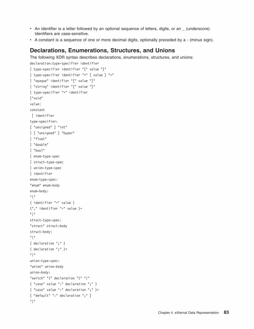
v An identifier is a letter followed by an optional sequence of letters, digits, or an _ (underscore).
Identifiers are case-sensitive.
v A constant is a sequence of one or more decimal digits, optionally preceded by a - (minus sign).
Declarations, Enumerations, Structures, and Unions
The following XDR syntax describes declarations, enumerations, structures, and unions:
declaration:type-specifier identifier
| type-specifier identifier "[" value "]"
| type-specifier identifier "<" [ value ] "<"
| "opaque" identifier "[" value "]"
| "string" identifier "[" value "]"
| type-specifier "*" identifier
|"void"
value:
constant
| identifier
type-specifier:
[ "unsigned" ] "int"
| [ "unsigned" ] "hyper"
| "float"
| "double"
| "bool"
| enum-type-spec
| struct-type-spec
| union-type-spec
| identifier
enum-type-spec:
"enum" enum-body
enum-body:
"{"
( identifier "=" value )
("," identifier "=" value )*
"}"
struct-type-spec:
"struct" struct-body
struct-body:
"{"
( declaration ";" )
( declaration ";" )*
"}"
union-type-spec:
"union" union-body
union-body:
"switch" "(" declaration ")" "{"
( "case" value ":" declaration ";" )
( "case" value ":" declaration ";" )*
[ "default" ":" declaration ";" ]
"}"
Chapter 4. eXternal Data Representation 83
constant-def:
"const" identifier "=" constant ";"
type-def
"typedef" declaration ";"
| "enum" identifier enum-body ";"
| "struct" identifier struct-body ";"
| "union" identifier union-body ";"
definition:
type-def
| constant-def
specification:
definition *
Syntax Notes
The following considerations pertain to XDR language syntax:
v The following keywords cannot be used as identifiers:
– bool
– case
– const
– default
– double
– enum
– float
– hyper
– opaque
– string
– struct
– switch
– typedef
– union
– unsigned
– void
v Only unsigned constants can be used as size specifications for arrays. If an identifier is used, it must be
declared previously as an unsigned constant in a const definition.
v In the scope of a specification, constant and type identifiers are in the same name space and must be
declared uniquely.
v Variable names must be unique in the scope of struct and union declarations. Nested struct and
union declarations create new scopes.
XDR Data Types
The following basic and constructed data types are defined in the eXternal Data Representation (XDR)
standard:
v “Integer Data Types” on page 85
v “Enumeration Data Types” on page 86
v “Boolean Data Types” on page 86
v “Floating-Point Data Types” on page 86
84 Communications Programming Concepts
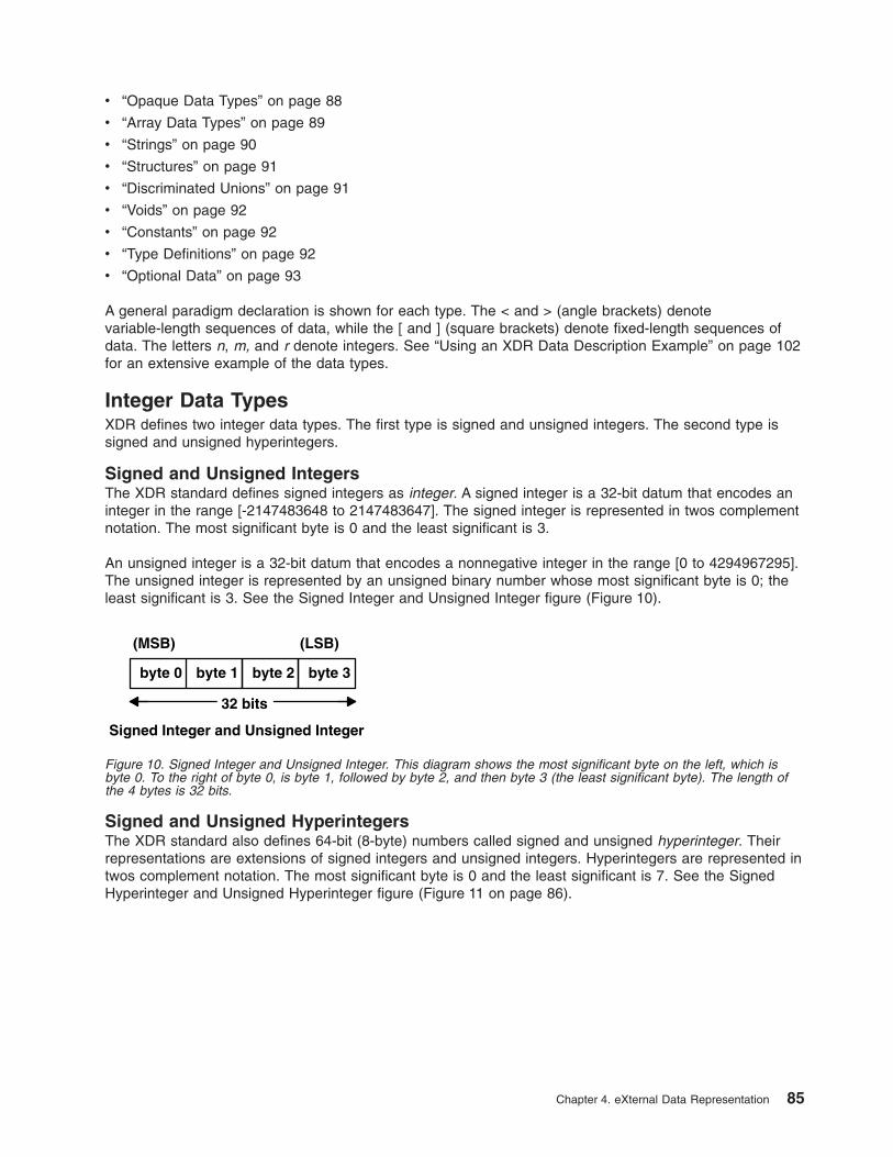
v “Opaque Data Types” on page 88
v “Array Data Types” on page 89
v “Strings” on page 90
v “Structures” on page 91
v “Discriminated Unions” on page 91
v “Voids” on page 92
v “Constants” on page 92
v “Type Definitions” on page 92
v “Optional Data” on page 93
A general paradigm declaration is shown for each type. The < and > (angle brackets) denote
variable-length sequences of data, while the [ and ] (square brackets) denote fixed-length sequences of
data. The letters n, m, and r denote integers. See “Using an XDR Data Description Example” on page 102
for an extensive example of the data types.
Integer Data Types
XDR defines two integer data types. The first type is signed and unsigned integers. The second type is
signed and unsigned hyperintegers.
Signed and Unsigned Integers
The XDR standard defines signed integers as integer. A signed integer is a 32-bit datum that encodes an
integer in the range [-2147483648 to 2147483647]. The signed integer is represented in twos complement
notation. The most significant byte is 0 and the least significant is 3.
An unsigned integer is a 32-bit datum that encodes a nonnegative integer in the range [0 to 4294967295].
The unsigned integer is represented by an unsigned binary number whose most significant byte is 0; the
least significant is 3. See the Signed Integer and Unsigned Integer figure (Figure 10).
Signed and Unsigned Hyperintegers
The XDR standard also defines 64-bit (8-byte) numbers called signed and unsigned hyperinteger. Their
representations are extensions of signed integers and unsigned integers. Hyperintegers are represented in
twos complement notation. The most significant byte is 0 and the least significant is 7. See the Signed
Hyperinteger and Unsigned Hyperinteger figure (Figure 11 on page 86).
byte 0 byte 1 byte 2 byte 3
32 bits
(MSB) (LSB)
Signed Integer and Unsigned Integer
Figure 10. Signed Integer and Unsigned Integer. This diagram shows the most significant byte on the left, which is
byte 0. To the right of byte 0, is byte 1, followed by byte 2, and then byte 3 (the least significant byte). The length of
the 4 bytes is 32 bits.
Chapter 4. eXternal Data Representation 85
Enumeration Data Types
The XDR standard provides enumerations for describing subsets of integers. XDR defines enumerations
as enum. Enumerations have the same representation as signed integers and are declared as follows:
enum { name-identifier = constant, ... } identifier;
Encoding any integers as enum, besides those assigned in the enum declaration, causes an error
condition.
Boolean Data Types
Booleans occur frequently enough to warrant an explicit data type in the XDR standard.
Booleans are declared as follows:
bool identifier;
This declaration is equivalent to:
enum { FALSE = 0, TRUE = 1 } identifier;
Floating-Point Data Types
The XDR standard defines two floating-point data types: single-precision and double-precision floating
points.
Single-Precision Floating Point
XDR defines the single-precision floating-point data type as a float. The length of a float is 32 bits, or 4
bytes. Floats are encoded using the IEEE standard for normalized single-precision floating-point numbers.
The single-precision floating-point number is declared as follows:
(-1)**S * 2**(E-Bias) * 1.F
S Sign of the number. This 1-bit field specifies either 0 for positive or 1 for negative.
E Exponent of the number in base 2. This field contains 8 bits. The exponent is biased by 127.
F Fractional part of the number’s mantissa in base 2. This field contains 23 bits.
See the Single-Precision Floating-Point figure (Figure 12 on page 87).
byte 0 byte 1 byte 2 byte 3
64 bits
(MSB) (LSB)
Signed Hyperinteger and Unsigned Hyperinteger
byte 4 byte 5 byte 6 byte 7
Figure 11. Signed Hyperinteger and Unsigned Hyperinteger. This diagram shows the most significant byte on the left
which is byte 0. To the right of byte 0, is byte 1, followed by byte 2, and byte 3 continued up to byte 7 (the least
significant byte). The length of the 8 bytes is 64 bits.
86 Communications Programming Concepts
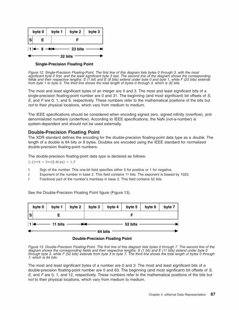
The most and least significant bytes of an integer are 0 and 3. The most and least significant bits of a
single-precision floating-point number are 0 and 31. The beginning (and most significant) bit offsets of S,
E, and F are 0, 1, and 9, respectively. These numbers refer to the mathematical positions of the bits but
not to their physical locations, which vary from medium to medium.
The IEEE specifications should be considered when encoding signed zero, signed infinity (overflow), and
denormalized numbers (underflow). According to IEEE specifications, the NaN (not-a-number) is
system-dependent and should not be used externally.
Double-Precision Floating Point
The XDR standard defines the encoding for the double-precision floating-point data type as a double. The
length of a double is 64 bits or 8 bytes. Doubles are encoded using the IEEE standard for normalized
double-precision floating-point numbers.
The double-precision floating-point data type is declared as follows:
(-1)**S * 2**(E-Bias) * 1.F
S Sign of the number. This one-bit field specifies either 0 for positive or 1 for negative.
E Exponent of the number in base 2. This field contains 11 bits. The exponent is biased by 1023.
F Fractional part of the number’s mantissa in base 2. This field contains 52 bits.
See the Double-Precision Floating Point figure (Figure 13).
The most and least significant bytes of a number are 0 and 3. The most and least significant bits of a
double-precision floating-point number are 0 and 63. The beginning (and most significant) bit offsets of S,
E, and F are 0, 1, and 12, respectively. These numbers refer to the mathematical positions of the bits but
not to their physical locations, which vary from medium to medium.
byte 0 byte 1 byte 2 byte 3
32 bits
Single-Precision Floating Point
S E F
1 23 bits 8
Figure 12. Single-Precision Floating-Point. The first line of this diagram lists bytes 0 through 3, with the most
significant byte 0 first, and the least significant byte 3 last. The second line of the diagram shows the corresponding
fields and their respective lengths: S (1 bit) and E (8 bits) extend under byte 0 and byte 1, while F (23 bits) extends
from byte 1 to byte 3. The third line shows the total length of bytes 0 through 3, which is 32 bits.
byte 0 byte 1 byte 2 byte 3
64 bits
Double-Precision Floating Point
S E F
1 52 bits 11 bits
byte 4 byte 5 byte 6 byte 7
Figure 13. Double-Precision Floating-Point. The first line of this diagram lists bytes 0 through 7. The second line of the
diagram shows the corresponding fields and their respective lengths: S (1 bit) and E (11 bits) extend under byte 0
through byte 2, while F (52 bits) extends from byte 3 to byte 7. The third line shows the total length of bytes 0 through
7, which is 64 bits.
Chapter 4. eXternal Data Representation 87
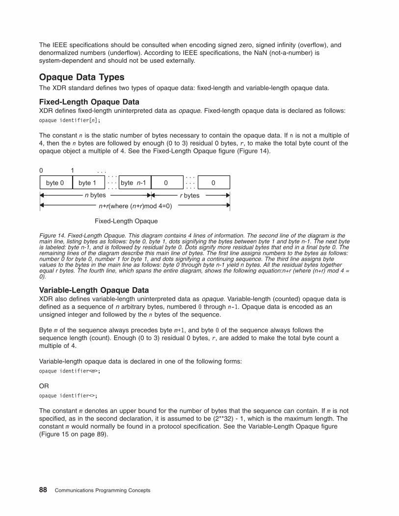
The IEEE specifications should be consulted when encoding signed zero, signed infinity (overflow), and
denormalized numbers (underflow). According to IEEE specifications, the NaN (not-a-number) is
system-dependent and should not be used externally.
Opaque Data Types
The XDR standard defines two types of opaque data: fixed-length and variable-length opaque data.
Fixed-Length Opaque Data
XDR defines fixed-length uninterpreted data as opaque. Fixed-length opaque data is declared as follows:
opaque identifier[n];
The constant n is the static number of bytes necessary to contain the opaque data. If n is not a multiple of
4, then the n bytes are followed by enough (0 to 3) residual 0 bytes, r, to make the total byte count of the
opaque object a multiple of 4. See the Fixed-Length Opaque figure (Figure 14).
Variable-Length Opaque Data
XDR also defines variable-length uninterpreted data as opaque. Variable-length (counted) opaque data is
defined as a sequence of n arbitrary bytes, numbered 0 through n-1. Opaque data is encoded as an
unsigned integer and followed by the n bytes of the sequence.
Byte m of the sequence always precedes byte m+1, and byte 0 of the sequence always follows the
sequence length (count). Enough (0 to 3) residual 0 bytes, r, are added to make the total byte count a
multiple of 4.
Variable-length opaque data is declared in one of the following forms:
opaque identifier<m>;
OR
opaque identifier<>;
The constant m denotes an upper bound for the number of bytes that the sequence can contain. If m is not
specified, as in the second declaration, it is assumed to be (2**32) - 1, which is the maximum length. The
constant m would normally be found in a protocol specification. See the Variable-Length Opaque figure
(Figure 15 on page 89).
Figure 14. Fixed-Length Opaque. This diagram contains 4 lines of information. The second line of the diagram is the
main line, listing bytes as follows: byte 0, byte 1, dots signifying the bytes between byte 1 and byte n-1. The next byte
is labeled: byte n-1, and is followed by residual byte 0. Dots signify more residual bytes that end in a final byte 0. The
remaining lines of the diagram describe this main line of bytes. The first line assigns numbers to the bytes as follows:
number 0 for byte 0, number 1 for byte 1, and dots signifying a continuing sequence. The third line assigns byte
values to the bytes in the main line as follows: byte 0 through byte n-1 yield n bytes. All the residual bytes together
equal r bytes. The fourth line, which spans the entire diagram, shows the following equation:n+r (where (n+r) mod 4 =
0).
88 Communications Programming Concepts

Note: Encoding a length n that is greater than the maximum described in the protocol specification causes
an error.
Array Data Types
The XDR standard defines two type of arrays: fixed-length and variable-length.
Fixed-Length Array
Fixed-length arrays of homogeneous elements are declared as follows:
type-name identifier[n];
Fixed-length arrays of elements are encoded by individually coding the elements of the array in their
natural order, 0 through n-1. Each element size is a multiple of 4 bytes. Although the elements are of the
same type, they may have different sizes. For example, in a fixed-length array of strings, all elements are
of the string type, yet each element varies in length. See the Fixed-Length Array figure (Figure 16).
Variable-Length Array
The XDR standard provides counted byte arrays for encoding variable-length arrays of homogeneous
elements. The array is encoded as the element count n (an unsigned integer) followed by the encoding of
each of the array’s elements, starting with element 0 and progressing through element n-1.
Variable-length arrays are declared as follows:
type-name identifier<m>;
OR
type-name identifier<>;
The constant m specifies the maximum acceptable element count of an array. If m is not specified, it is
assumed to be (2**32) - 1. See the Variable-Length Array figure (Figure 17 on page 90).
Figure 15. Variable-Length Opaque. This diagram contains 4 lines of information. The second line of the diagram is
the main line, listing segments as follows: length n, byte 0, byte 1, and then dots signifying the bytes between byte 1
and byte n-1. The next byte is labeled:n-1, followed by residual byte 0. Dots signify more residual bytes that end in a
final byte 0. The remaining lines of the diagram describe this main line. The first line assigns numbers as follows:
numbers 0 through 3 for length n, number 4 for byte 0, number 5 for byte 1, and dots signifying a continuing
sequence. The third line assigns byte values to the main line as follows: length n is 4 bytes, byte 0 through byte n-1
yield n bytes. All the residual bytes together equal r bytes. The fourth line, which spans the entire diagram, shows the
following equation:n+r (where (n+r) mod 4 = 0).
Figure 16. Fixed-Length Array. This diagram shows from the left, element 0, element 1, a series of dots to signify the
elements between element 1 and element n-1. The length is equal to n elements.
Chapter 4. eXternal Data Representation 89
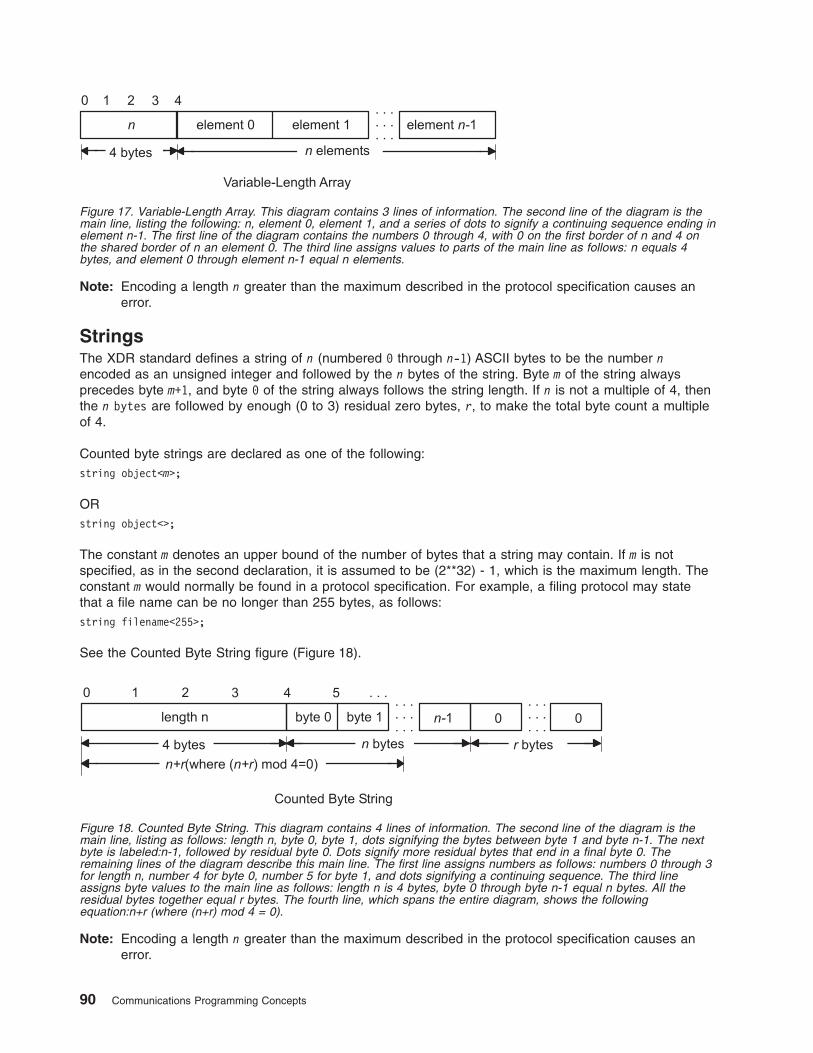
Note: Encoding a length n greater than the maximum described in the protocol specification causes an
error.
Strings
The XDR standard defines a string of n (numbered 0 through n-1) ASCII bytes to be the number n
encoded as an unsigned integer and followed by the n bytes of the string. Byte m of the string always
precedes byte m+1, and byte 0 of the string always follows the string length. If n is not a multiple of 4, then
the n bytes are followed by enough (0 to 3) residual zero bytes, r, to make the total byte count a multiple
of 4.
Counted byte strings are declared as one of the following:
string object<m>;
OR
string object<>;
The constant m denotes an upper bound of the number of bytes that a string may contain. If m is not
specified, as in the second declaration, it is assumed to be (2**32) - 1, which is the maximum length. The
constant m would normally be found in a protocol specification. For example, a filing protocol may state
that a file name can be no longer than 255 bytes, as follows:
string filename<255>;
See the Counted Byte String figure (Figure 18).
Note: Encoding a length n greater than the maximum described in the protocol specification causes an
error.
Figure 17. Variable-Length Array. This diagram contains 3 lines of information. The second line of the diagram is the
main line, listing the following: n, element 0, element 1, and a series of dots to signify a continuing sequence ending in
element n-1. The first line of the diagram contains the numbers 0 through 4, with 0 on the first border of n and 4 on
the shared border of n an element 0. The third line assigns values to parts of the main line as follows: n equals 4
bytes, and element 0 through element n-1 equal n elements.
Figure 18. Counted Byte String. This diagram contains 4 lines of information. The second line of the diagram is the
main line, listing as follows: length n, byte 0, byte 1, dots signifying the bytes between byte 1 and byte n-1. The next
byte is labeled:n-1, followed by residual byte 0. Dots signify more residual bytes that end in a final byte 0. The
remaining lines of the diagram describe this main line. The first line assigns numbers as follows: numbers 0 through 3
for length n, number 4 for byte 0, number 5 for byte 1, and dots signifying a continuing sequence. The third line
assigns byte values to the main line as follows: length n is 4 bytes, byte 0 through byte n-1 equal n bytes. All the
residual bytes together equal r bytes. The fourth line, which spans the entire diagram, shows the following
equation:n+r (where (n+r) mod 4 = 0).
90 Communications Programming Concepts
Structures
Using the primitive routines, the programmer can write unique XDR routines to describe arbitrary data
structures such as elements of arrays, arms of unions, or objects pointed to from other structures. The
structures themselves may contain arrays of arbitrary elements or pointers to other structures.
Structures are declared as follows:
struct {
component-declaration-A;
component-declaration-B;
...
} identifier;
In a structure, the components are encoded in the order of their declaration in the structure. Each
component size is a multiple of four bytes, although the components may have different sizes. See the
Structure figure (Figure 19).
Discriminated Unions
A discriminated union is a union data structure that holds various objects, with one of the objects identified
directly by a discriminant. The discriminant is the first item to be serialized or deserialized. A discriminated
union includes both a discriminant and a component. The type of discriminant is either integer, unsigned
integer, or an enumerated type, such as bool. The component is selected from a set of types that are
prearranged according to the value of the discriminant. The component types are called arms of the union.
The arms of a discriminated union are preceded by the value of the discriminant that implies their
encoding. See “Using an XDR Discriminated Union Example” on page 107.
Discriminated unions are declared as follows:
union switch (discriminant-declaration) {
case discriminant-value-A:
arm-declaration-A;
case discriminant-value-B:
arm-declaration-B;
...
default: default-declaration;
} identifier;
Each case keyword is followed by a legal value of the discriminant. The default arm is optional. If an arm
is not specified, a valid encoding of the union cannot take on unspecified discriminant values. The size of
the implied arm is always a multiple of four bytes.
The discriminated union is encoded as the discriminant, followed by the encoding of the implied arm.
See the Discriminated Union figure (Figure 20 on page 92).
Structure
. . .
. . .
. . .component A component B
Figure 19. Structure. This diagram shows a line of components side by side as follows: component A, component B,
and dots signifying a continuing sequence.
Chapter 4. eXternal Data Representation 91
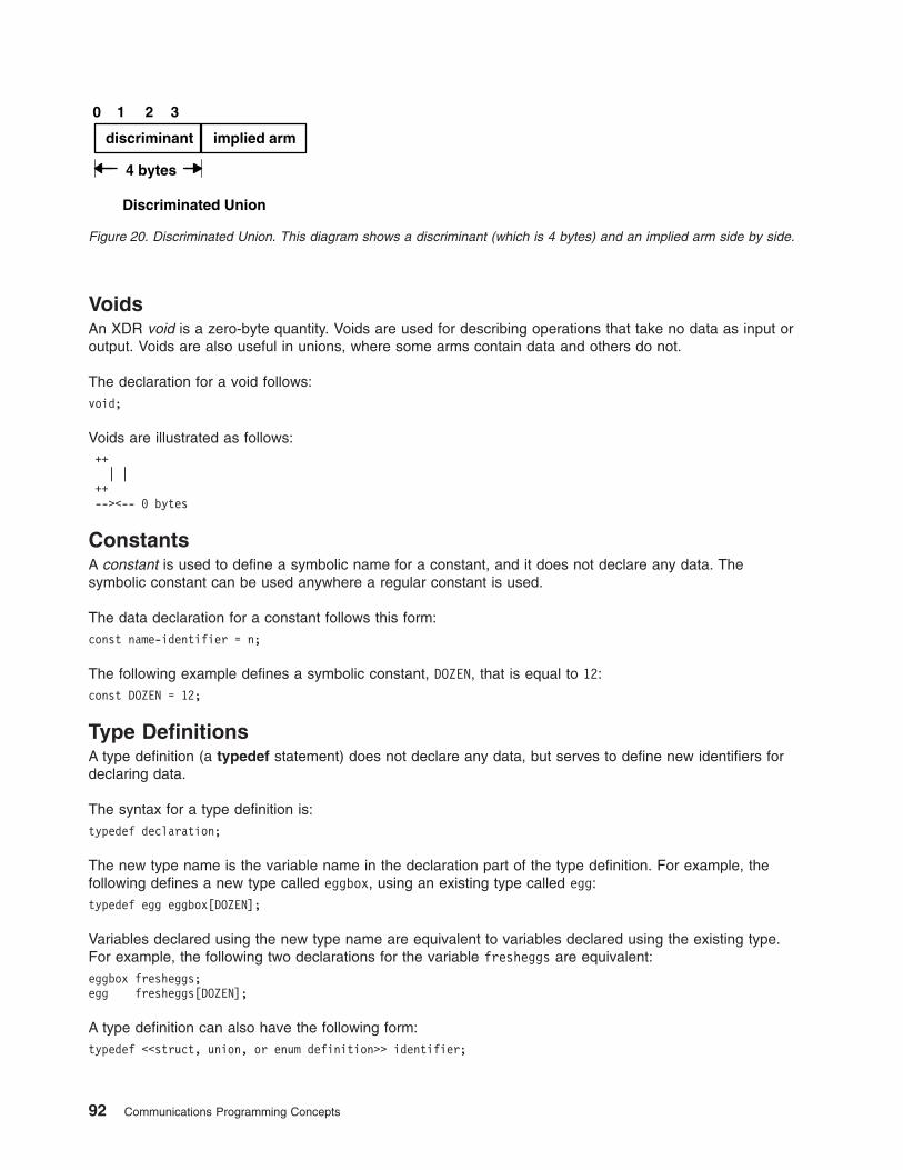
Voids
An XDR void is a zero-byte quantity. Voids are used for describing operations that take no data as input or
output. Voids are also useful in unions, where some arms contain data and others do not.
The declaration for a void follows:
void;
Voids are illustrated as follows:
++
| |
++
--><-- 0 bytes
Constants
A constant is used to define a symbolic name for a constant, and it does not declare any data. The
symbolic constant can be used anywhere a regular constant is used.
The data declaration for a constant follows this form:
const name-identifier = n;
The following example defines a symbolic constant, DOZEN, that is equal to 12:
const DOZEN = 12;
Type Definitions
A type definition (a typedef statement) does not declare any data, but serves to define new identifiers for
declaring data.
The syntax for a type definition is:
typedef declaration;
The new type name is the variable name in the declaration part of the type definition. For example, the
following defines a new type called eggbox, using an existing type called egg:
typedef egg eggbox[DOZEN];
Variables declared using the new type name are equivalent to variables declared using the existing type.
For example, the following two declarations for the variable fresheggs are equivalent:
eggbox fresheggs;
egg fresheggs[DOZEN];
A type definition can also have the following form:
typedef <<struct, union, or enum definition>> identifier;
Discriminated Union
discriminant implied arm
4 bytes
0 1 2 3
Figure 20. Discriminated Union. This diagram shows a discriminant (which is 4 bytes) and an implied arm side by side.
92 Communications Programming Concepts
An alternative type definition form is preferred for structures, unions, and enumerations. The type definition
form can be converted to the alternative form by removing the typedef keyword and placing the identifier
after the struct, union, or enum keyword, instead of at the end. For example, here are the two ways to
define the type bool:
enum bool { /* preferred alternative */
FALSE = 0,
TRUE = 1
};
OR
typedef enum {F=0, T=1} bool;
The first syntax is preferred because the programmer does not have to wait until the end of a declaration
to determine the name of the new type.
Optional Data
Optional data is a type of union that occurs so frequently it has its own syntax. The optional data type is
closely coordinated to the representation of recursive data structures by the use of pointers in high-level
languages, such as C or Pascal. The syntax for pointers is the same as that for C language.
The syntax for optional data is as follows:
type-name *identifier;
The declaration for optional data is equivalent to the following union:
union switch (bool opted) {
case TRUE:
type-name element;
case FALSE:
void;
} identifier;
Because bool opted can be interpreted as the length of the array, the declaration for optional data is also
equivalent to the following variable-length array declaration:
type-name identifier<1>;
Optional data is very useful for describing recursive data structures such as linked lists and trees. For
example, the following defines a stringlist type that encodes lists of arbitrary length strings:
struct *stringlist {
string item<>;
stringlist next;
};
The example can be equivalently declared as a union, as follows:
union stringlist switch (bool opted) {
case TRUE:
struct {
string item<>;
stringlist next;
} element;
case FALSE:
void;
};
The example can also be declared as a variable-length array, as follows:
struct stringlist<1> {
string item<>;
stringlist next;
};
Chapter 4. eXternal Data Representation 93
Because both the union and the array declarations obscure the intention of the stringlist type, the optional
data declaration is preferred.
List of XDR Programming References
The list of eXternal Data Representation (XDR) programming references includes:
v “XDR Library Filter Primitives”
v “XDR Library Non-Filter Primitives”
v “Examples” on page 95
XDR Library Filter Primitives
xdr_array Translates between variable-length arrays and their corresponding external
representations.
xdr_bool Translates between Booleans and their external representations.
xdr_bytes Translates between internal counted byte string arrays and their external representations.
xdr_char Translates between C language characters and their external representations.
xdr_double Translates between C language double-precision numbers and their external
representations.
xdr_enum Translates between C language enumerations and their external representations.
xdr_float Translates between C language floats and their external representations.
xdr_int Translates between C language integers and their external representations.
xdr_long Translates between C language long integers and their external representations.
xdr_opaque Translates between opaque data and its external representation.
xdr_reference Provides pointer chasing within structures.
xdr_short Translates between C language short integers and their external representations.
xdr_string Translates between C language strings and their external representations.
xdr_u_char Translates between unsigned C language characters and their external representations.
xdr_u_int Translates between C language unsigned integers and their external representations.
xdr_u_long Translates between C language unsigned long integers and their external
representations.
xdr_u_short Translates between C language unsigned short integers and their external
representations.
xdr_union Translates between discriminated unions and their external representations.
xdr_vector Translates between fixed-length arrays and their corresponding external representations.
xdr_void Supplies an XDR subroutine to the Remote Procedure Call (RPC) system without
transmitting data.
xdr_wrapstring Calls the xdr_string subroutine.
XDR Library Non-Filter Primitives
xdr_destroy Destroys the XDR stream pointed to by the xdrs parameter.
xdr_free Deallocates or frees memory.
xdr_getpos Returns an unsigned integer that describes the current position in the data
stream.
xdr_inline Returns a pointer to an internal piece of the buffer of a stream, pointed to by the
xdrs parameter.
xdr_pointer Provides pointer chasing within structures and serializes null pointers.
xdr_setpos Changes the current position in the XDR stream.
xdrmem_create Initializes in local memory the XDR stream pointed to by the xdrs parameter.
xdrrec_create Provides an XDR stream that can contain long sequences of records.
xdrrec_endofrecord Causes the current outgoing data to be marked as a record.
xdrrec_eof Checks the buffer for an input stream.
94 Communications Programming Concepts
xdrrec_skiprecord Causes the position of an input stream to move to the beginning of the next
record.
xdrstdio_create Initializes the XDR data stream pointed to by the xdrs parameter.
Examples
See the following examples:
v “Passing Linked Lists Using XDR Example” on page 100
v “Using an XDR Data Description Example” on page 102
v “Showing the Justification for Using XDR Example” on page 103
v “Using XDR Example” on page 105
v “Using XDR Array Examples” on page 106
v “Using an XDR Discriminated Union Example” on page 107
v “Showing the Use of Pointers in XDR Example” on page 108
XDR Library Filter Primitives
The eXternal Data Representation (XDR) primitives are subroutines that define the basic and constructed
data types. The XDR language provides programmers with a specification for uniform representations that
includes filter primitives for basic and constructed data types. The basic data types include integers,
enumerations, Booleans, hyperintegers, floating points, and void data. The constructed data types include
strings, structures, byte arrays, arrays, opaque data, unions, and pointers.
The XDR standard translates both basic and constructed data types. For basic data types, XDR provides
basic filter primitives (see “XDR Basic Filter Primitives”) that serialize information from the local host’s
representation to the XDR representation and deserialize information from the XDR representation to the
local host’s representation. For constructed data types, XDR provides constructed filter primitives (see
“XDR Constructed Filter Primitives” on page 96) that allow the use of basic data types, such as integers
and floating-point numbers, to create more complex constructs such as arrays and discriminated unions.
Remote Procedure Calls (RPCs) use XDR to establish uniform representations for data types to transfer
the call message data between machines. Although the XDR constructs resemble the C programming
language, C language constructs define the code for programs. XDR, however, standardizes the
representation of data types directly in the programming code.
XDR Basic Filter Primitives
The XDR primitives are subroutines that define the basic and constructed data types. The basic data type
filter primitives include the following:
v “Number Filter Primitives”
v “Floating-Point Filter Primitives” on page 96
v “Enumeration Filter Primitives” on page 96
v “Passing No Data” on page 96
Number Filter Primitives
The XDR library provides basic filter primitives that translate between types of numbers and their external
representations. The XDR number filters cover signed and unsigned integers, as well as signed and
unsigned short and long integers.
The subroutines for the XDR number filters are:
xdr_int Translates between C language integers and their external representations.
xdr_u_int Translates between C language unsigned integers and their external representations.
Chapter 4. eXternal Data Representation 95
xdr_long Translates between C language long integers and their external representations.
xdr_u_long Translates between C language unsigned long integers and their external representations.
xdr_short Translates between C language short integers and their external representations.
xdr_u_short Translates between C language unsigned short integers and their external representations.
Floating-Point Filter Primitives
The XDR library provides primitives that translate between floating-point data and their external
representations. Floating-point data encodes an integer with an exponent. Floats and double-precision
numbers compose floating-point data.
Note: Numbers are represented as IEEE standard floating points. Subroutines may fail when decoding
IEEE representations into machine-specific representations, or vice versa.
The subroutines for the XDR floating-point filters are:
xdr_double Translates between C language double-precision numbers and their external representations.
xdr_float Translates between C language floats and their external representations.
Enumeration Filter Primitives
The XDR library provides a primitive for generic enumerations based on the assumption that a C
enumeration value (enum) has the same representation. There is a special enumeration in XDR known as
the Boolean.
The subroutines for the XDR library enumeration filters are:
xdr_bool Translates between Booleans and their external representations.
xdr_enum Translates between C language enumerations and their external representations.
Passing No Data
Sometimes an XDR subroutine must be supplied to the RPC system, but no data is required or passed.
The XDR library provides the following primitive for this function:
xdr_void Supplies an XDR subroutine to the RPC system without transmitting data.
XDR Constructed Filter Primitives
The XDR filter primitives are subroutines that define the basic and constructed data types. Constructed
data type filters allow complex data types to be created from basic data types. Constructed data types
require more parameters to perform more complicated functions than do basic data types. Memory
management is an example of a more complicated function that can be performed with the constructed
primitives. Memory is allocated when deserializing data with the xdr_decode subroutine. Memory is
deallocated through the xdr_free subroutine.
The constructed data-type filter primitives include the following:
v “String Filter Primitives” on page 97
v “Array Filter Primitives” on page 97
v “Opaque-Data Filter Primitives” on page 97
v “Primitive for Pointers to Structures” on page 97
v “Primitive for Discriminated Unions” on page 98
96 Communications Programming Concepts
String Filter Primitives
A string is a constructed filter primitive that consists of a sequence of bytes terminated by a null byte. The
null byte does not figure into the length of the string. Externally, strings are represented by a sequence of
ASCII characters. Internally, XDR uses the char * designation to represent pointers to strings.
The XDR library includes primitives for the following string routines:
xdr_string Translates between C language strings and their external representations.
xdr_wrapstring Calls the xdr_string subroutine.
Array Filter Primitives
Arrays are constructed filter primitives and can be either generic arrays or byte arrays. The XDR library
provides filter primitives for handling both types of arrays.
Generic Arrays: Generic arrays consist of arbitrary elements. Generic arrays are handled in much the
same way as byte arrays, which handle a subset of generic arrays where the size of the arbitrary elements
is 1, and their external descriptions are predetermined. The primitive for generic arrays requires an
additional parameter to define the size of the element in the array and to call an XDR subroutine to
encode or decode each element in the array.
The XDR library includes the following subroutines for generic arrays:
xdr_array Translates between variable-length arrays and their corresponding external representations.
xdr_vector Translates between fixed-length arrays and their corresponding external representations.
Byte Arrays: The XDR library provides a primitive for byte arrays. Although similar to strings, byte arrays
differ by having a byte count. That is, the length of the array is set by an unsigned integer. They also differ
in that byte arrays are not terminated with a null character. External and internal representations of byte
arrays are the same.
The XDR library includes the following subroutine for byte arrays:
xdr_bytes Translates between counted byte string arrays and their external representations.
Opaque-Data Filter Primitives
Opaque data is composed of bytes of a fixed size that are not interpreted as they pass through the data
streams. Opaque data bytes, such as handles, are passed between server and client without being
inspected by the client. The client uses the data as it is and then returns it to the server. By definition, the
actual data contained in the opaque object is not portable between computers.
The XDR library includes the following subroutine for opaque data:
xdr_opaque Translates between opaque data and its external representation.
Primitive for Pointers to Structures
The XDR library provides a primitive for pointers so that structures referenced within other structures can
be easily serialized, deserialized, and freed. The XDR library includes the following subroutine for pointers
to structures:
xdr_reference Provides pointer chasing within structures.
Chapter 4. eXternal Data Representation 97
Primitive for Discriminated Unions
A discriminated union is a C language union, which is an object that holds several data types. One arm of
the union is an enumeration value, or discriminant, that holds a specific object to be processed over the
system first. The discriminant is an enumeration value (enum_t).
The XDR library includes the following subroutine for discriminated unions:
xdr_union Translates between discriminated unions and their external representations.
XDR Non-Filter Primitives
The eXternal Data Representation (XDR) nonfilter primitives are used to create, manipulate, implement,
and destroy XDR data streams. These primitives allow programmers to destroy a data stream (freeing its
private structure) for example, or change a data stream position.
The following sections are discussed in this section:
v “Creating and Using XDR Data Streams”
v “Manipulating an XDR Data Stream” on page 99
v “Implementing an XDR Data Stream” on page 99
v “Destroying an XDR Data Stream” on page 100
Creating and Using XDR Data Streams
XDR data streams are obtained by calling creation subroutines that take arguments specifically designed
to the properties of the stream. There are existing XDR data streams for serializing or deserializing data in
standard input and output streams, memory streams, and record streams.
Note: Remote Procedure Call (RPC) clients do not have to create XDR streams because the RPC system
creates and passes these streams to the client.
The types of data streams include standard I/O streams, memory streams, and record streams.
Standard I/O Streams
XDR data streams serialize and deserialize standard input and output by calling the standard I/O creation
subroutine to initialize the XDR data stream pointed to by the xdrs parameter.
The XDR library includes the following subroutine for standard I/O data streams:
xdrstdio_create Initializes the XDR data stream pointed to by the xdrs parameter.
Memory Streams
XDR data streams serialize and deserialize data from memory by calling the XDR memory creation
subroutine to initialize in local memory the XDR stream pointed to by the xdrs parameter. In RPC, the User
Datagram Protocol (UDP) Internet Protocol (IP) implementation uses this subroutine to build entire
call-and-reply messages in memory before sending a message to the recipient.
The XDR library includes the following subroutine for memory data streams:
xdrmem_create Initializes in local memory the XDR stream pointed to by the xdrs parameter.
Record Streams
Record streams are XDR streams built on top of record fragments, which are built on TCP/IP streams.
TCP/IP is a connection protocol for transporting large streams of data at one time, instead of transporting
a single data packet at a time.
98 Communications Programming Concepts
Record streams are primarily used to make connections between remote procedure calls and TCP. They
can also be used to stream data into or out of normal files.
XDR provides the following subroutines for use with record streams:
xdrrec_create Provides an XDR stream that can contain long sequences of records.
xdrrec_endofrecord Causes the current outgoing data to be marked as a record.
xdrrec_eof Checks the buffer for an input stream that identifies the end of file (EOF).
xdrrec_skiprecord Causes the position of an input stream to move to the beginning of the next
record.
Manipulating an XDR Data Stream
XDR provides the following subroutines for describing and changing data stream position:
xdr_getpos Returns an unsigned integer that describes the current position of the data stream.
xdr_setpos Changes the current position of the data stream.
Implementing an XDR Data Stream
Programmers can create and implement XDR data streams. The following example shows the abstract
data types (XDR handle) required. The example contains operations being applied to the stream, an
operation vector for the implementation, and two private fields for use by the implementation.
enum xdr_op { XDR_ENCODE=0, XDR_DECODE=1, XDR_FREE=2 };
typedef struct {
enum xdr_op x_op;
struct xdr_ops {
bool_t (*x_getlong) ();
boot_t (*x_putlong) ();
boot_t (*x_getbytes) ();
boot_t (*x_putbytes) ();
u_int (*x_getpostn) ();
boot_t (*x_setpostn) ();
caddr_t (*x_inline) ();
VOID (*x_destroy) ();
} *XOp;
caddr_t x_public;
caddr_t x_private;
caddr_t x_base;
int x_handy;
} XDR;
The following parameters are pointers to XDR stream manipulation subroutines:
x_destroy Frees private data structures.
x_getbytes Gets bytes from the data stream.
x_getlong Gets long integer values from the data stream.
x_getpostn Returns stream offset.
x_inline Points to internal data buffer, which can be used for any purpose.
x_putbytes Puts bytes into the data stream.
x_putlong Puts long integer values into the data stream.
x_setpostn Repositions offset.
XOp Specifies the current operation being performed on the stream. This field is important to the XDR
primitives. However, the stream’s implementation does not depend on the value of this parameter.
The following fields are specific to a stream’s implementation:
x_base Contains position information in the data stream that is private to the user implementation.
Chapter 4. eXternal Data Representation 99
x_handy Contains extra information, as necessary.
x_public Specifies user data that is private to the stream’s implementation and is not used by the XDR
primitive.
x_private Points to the private data.
Destroying an XDR Data Stream
The following subroutine destroys a specific XDR data stream:
xdr_destroy Destroys the XDR data stream pointed to by the xdrs parameter, freeing the private data
structures allocated to the stream.
The use of the XDR data stream handle is undefined after it is destroyed.
Passing Linked Lists Using XDR Example
Linked lists of arbitrary length can be passed using eXternal Data Representation (XDR). To help illustrate
the functions of the XDR routine for encoding, decoding, or freeing linked lists, this example creates a data
structure and defines its associated XDR routine.
“Using XDR Example” on page 105 presents a C data structure and its associated XDR routines for an
individual’s gross assets and liabilities. The example is duplicated below:
struct gnumbers {
long g_assets;
long g_liabilities;
};
bool_t
xdr_gnumbers (xdrs, gp)
XDR *xdrs;
struct gnumbers *gp;
{
if (xdr_long (xdrs, &(gp->g_assets)))
return (xdr_long (xdrs, &( gp->g_liabilities)));
return(FALSE);
}
xdrs Points to the XDR data stream handle.
gp Points to the address of the structure that provides the data to or from the XDR stream.
For implementing a linked list of such information, a data structure could be constructed as follows:
struct gnumbers_node {
struct gnumbers gn_numbers;
struct gnnumbers_node *gn_next;
};
typedef struct gnumbers_node *gnumbers_list;
The head of the linked list can be thought of as the data object; that is, the head is not merely a
convenient shorthand for a structure. Similarly, the gn_next field indicates whether or not the object has
terminated. However, if the object continues, the gn_next field also specifies the address where it
continues. The link addresses carry no useful information when the object is serialized.
The XDR data description of this linked list can be described by the recursive declaration of the
gnumbers_list field, as follows:
struct gnumbers {
int g_assets;
int g_liabilities;
};
100 Communications Programming Concepts
struct gnumbers_node {
gnumbers gn_numbers;
gnumbers_node *gn_next;
};
In the following description, the Boolean indicates if more data follows it. If the Boolean is a False value, it
is the last data field of the structure. If it is a True value, it is followed by a gnumbers structure and,
recursively, by a gnumbers_list. The C declaration has no Boolean explicitly declared in it (though the
gn_next field implicitly carries the information), while the XDR data description has no pointer explicitly
declared in it.
Hints for writing the XDR routines for a gnumbers_list structure follow easily from the previous XDR
description. The following primitive, xdr_pointer, implements the previous XDR union:
bool_t
xdr_gnumbers_node (xdrs, gn)
XDR *xdrs;
gnumbers_node *gn;
{
return (xdr_gnumbers (xdrs, &gn->gn_numbers) &&
xdr_gnumbers_list (xdrs, &gp->gn_next));
bool_t
xdr_gnumbers_list (xdrs, gnp)
XDR *xdrs;
gnumbers_list *gnp;
{
return (xdr_pointer (xdrs, gnp,
SizeOf(struct gnumbers_node),
xdr_gnumbers_node));
As a result of using XDR on a list with these subroutines, the C stack grows linearly with respect to the
number of nodes in the list. This is due to the recursion. The following subroutine collapses the previous
two recursive programs into a single, nonrecursive one:
bool_t
xdr_gnumbers_list (xdrs, gnp)
XDR *xdrs;
gnumbers_list *gnp;
{
bool_t more_data;
gnumbers_list *nextp;
for (;;) {
more_data = (*gnp != NULL);
if (!xdr_bool (xdrs, &more_data)) {
return (FALSE) ;
}
if (!more_data) {
break;
}
if (xdrs->x_op == XDR_FREE) {
nextp = &(*gnp)->gn_next;
}
if (!xdr_reference (xdrs, gnp,
sizeof (struct gnumbers_node), xdr_gnumbers)) {
return (FALSE);
}
gnp = xdrs->x_op == XDR_FREE) ?
nextp : &(*gnp)->gn_next;
}
*gnp = NULL;
return (TRUE)
}
Chapter 4. eXternal Data Representation 101
The first statement determines whether more data exists, so that this Boolean information can be
serialized. This statement is unnecessary in the XDR_DECODE case, because the value of the more_data
field is not known until the next statement deserializes it.
The next statement translates the more_data field of the XDR union. If no more data exists, set this last
pointer to Null to indicate the end of the list and return True because the operation is done.
Note: Setting the pointer to Null is important only in the XDR_ENCODE case because the pointer is already
null in the XDR_ENCODE and XDR_FREE cases.
Next, if the direction is XDR_FREE, the value of the nextp field is set to indicate the location of the next
pointer in the list. This step dereferences the gnp field to find the location of the next item in the list. After
the next statement, the storage pointed to by gnp is freed and no longer valid. This step is not taken for all
directions because, in the XDR_DECODE direction, the value of the gnp field will not be set until the next
statement.
The next statement translates the data in the node using the xdr_reference primitive. The xdr_reference
subroutine is similar to the xdr_pointer subroutine, used previously, but it does not send over the Boolean
indicating whether there is more data. The program uses the xdr_reference subroutine instead of the
xdr_pointer subroutine because the information is already translated by XDR. Notice that the XDR
subroutine passed is not the same type as an element in the list. The subroutine passed is
xdr_gnumbers, for translating gnumbers, but each element in the list is actually of the gnumbers_node
type. The xdr_gnumbers_gnode subroutine is not passed because it is recursive. The program instead
uses xdr_gnumbers, which translates all nonrecursive portions.
Note: This method works only if the gn_numbers field is the first item in each element, so that their
addresses are identical when passed to the xdr_reference primitive.
Finally, the program updates the gnp field to point to the next item in the list. If the direction is
XDR_FREE, it is set to the previously saved value. Otherwise, the program dereferences the gnp field to
get the proper value. Though harder to understand than the recursive version, this nonrecursive subroutine
is far less likely to cause errors in the C stack. The nonrecursive subroutine also runs more efficiently
because much procedure call overhead has been removed. For small lists, containing hundreds of items
or less, the recursive version of the subroutine should be sufficient.
Using an XDR Data Description Example
The following short eXternal Data Representation (XDR) data description of a file can be used to transfer
files from one machine to another:
const MAXUSERNAME = 32; /* max length of a user name */
const MAXFILELEN = 65535; /* max length of a file */
const MAXNAMELEN = 255; /* max length of a file name */
/*
* Types of files:
*/
enum filekind {
TEXT = 0, /* ascii data */
DATA = 1, /* raw data */
EXEC = 2 /* executable */
};
/*
* File information, per kind of file:
*/
union filetype switch (filekind kind) {
case TEXT:
void; /* no extra information */
case DATA:
string creator<MAXNAMELEN>; /* data creator */
case EXEC:
102 Communications Programming Concepts
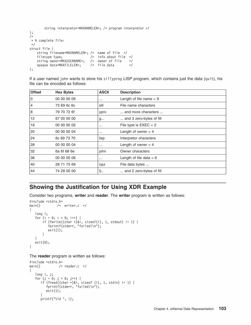
string interpretor<MAXNAMELEN>; /* program interpretor */
};
/*
* A complete file:
*/
struct file {
string filename<MAXNAMELEN>; /* name of file */
filetype type; /* info about file */
string owner<MAXUSERNAME>; /* owner of file */
opaque data<MAXFILELEN>; /* file data */
};
If a user named john wants to store his sillyprog LISP program, which contains just the data (quit), his
file can be encoded as follows:
Offset Hex Bytes ASCII Description
0 00 00 00 09 ... Length of file name = 9
4 73 69 6c 6c sill File name characters
8 79 70 72 6f ypro ... and more characters ...
12 67 00 00 00 g... ... and 3 zero-bytes of fill
16 00 00 00 02 ... File type is EXEC = 2
20 00 00 00 04 ... Length of owner = 4
24 6c 69 73 70 lisp Interpretor characters
28 00 00 00 04 ... Length of owner = 4
32 6a 6f 68 6e john Owner characters
36 00 00 00 06 ... Length of file data = 6
40 28 71 75 69 (qui File data bytes ...
44 74 29 00 00 t).. ... and 2 zero-bytes of fill
Showing the Justification for Using XDR Example
Consider two programs, writer and reader. The writer program is written as follows:
#include <stdio.h>
main() /* writer.c */
{
long i;
for (i = 0; i < 8; i++) {
if (fwrite((char *)&i, sizeof(i), 1, stdout) != 1) {
fprintf(stderr, "failed!\n");
exit(1);
}
}
exit(0);
}
The reader program is written as follows:
#include <stdio.h>
main() /* reader.c */
{
long i, j;
for (j = 0; j < 8; j++) {
if (fread((char *)&i, sizeof (i), 1, stdin) != 1) {
fprintf(stderr, "failed!\n");
exit(1);
}
printf("%ld ", i);
Chapter 4. eXternal Data Representation 103
}
printf("\n");
exit(0);
}
The two programs appear to be portable because they pass lint checking and exhibit the same behavior
when executed on two different hardware architectures, such as an IBM machine and a VAX machine.
Piping the output of the writer program to the reader program gives identical results on an IBM machine
or a VAX machine, as follows:
ibm% writer | reader
0 1 2 3 4 5 6 7
ibm%
vax% writer | reader
0 1 2 3 4 5 6 7
vax%
The following output results if the first program produces data on an IBM machine and the second
consumes data on a VAX machine:
ibm% writer | rsh vax reader
0 16777216 33554432 50331648 67108864 83886080 100663296
117440512
ibm%
Executing the writer program on the VAX machine and the reader program on the IBM machine produces
results identical to the previous example. These results occur because the byte ordering of long integers
differs between the VAX machine and the IBM machine, even though word size is the same.
Note: The value 16777216 equals 224 . When 4 bytes are reversed, the 1 winds up in the 24th bit.
Data must be portable when shared by two or more machine types. Programs can be made data-portable
by replacing the read and write system calls with calls to the xdr_long subroutine, which is a filter that
interprets the standard representation of a long integer in its external form.
Following is the revised version of the writer program:
#include <stdio.h>
#include <rpc/rpc.h> /* xdr is a sub-library of rpc */
main() /* writer.c */
{
XDR xdrs;
long i;
xdrstdio_create(&xdrs, stdout, XDR_ENCODE);
for (i = 0; i < 8; i++) {
if (!xdr_long(&xdrs, &i)) {
fprintf(stderr, "failed!\n");
exit(1);
}
}
exit(0);
}
Following is the result of the reader program:
#include <stdio.h>
#include <rpc/rpc.h> /* xdr is a sub-library of rpc */
main() /* reader.c */
{
XDR xdrs;
long i, j;
xdrstdio_create(&xdrs, stdin, XDR_DECODE);
for (j = 0; j < 8; j++) {
if (!xdr_long(&xdrs, &i)) {
104 Communications Programming Concepts
fprintf(stderr, "failed!\n");
exit(1);
}
printf("%ld ", i);
}
printf("\n");
exit(0);
}
The new programs, executed on an IBM machine, then on a VAX machine, and then from an IBM to a
VAX, yield the following results:
ibm% writer | reader
0 1 2 3 4 5 6 7
ibm%
vax% writer | reader
0 1 2 3 4 5 6 7
vax%
ibm% writer | rsh vax reader
0 1 2 3 4 5 6 7
ibm%
Integers are one type of portable data. Arbitrary data structures present portability problems, particularly
with respect to alignment and pointers. Alignment on word boundaries can cause the size of a structure to
vary from machine to machine. Pointers, though convenient to use, have meaning only on the machine
where they are defined.
Using XDR Example
Assume that a person’s gross assets and liabilities are to be exchanged among processes. Also, assume
that these values are important enough to warrant their own data type:
struct gnumbers {
long g_assets;
long g_liabilities;
};
The corresponding eXternal Data Representaton (XDR) routine describing this structure would be:
bool_t /* TRUE is success, FALSE is failure */
xdr_gnumbers(xdrs, gp)
XDR *xdrs;
struct gnumbers *gp;
{
if (xdr_long(xdrs, &gp->g_assets) &&
xdr_long(xdrs, &gp->g_liabilities))
return(TRUE);
return(FALSE);
}
The xdrs parameter is neither inspected nor modified before being passed to the subcomponent routines.
However, programs should always inspect the return value of each XDR routine call, and immediately give
up and return False if the subroutine fails.
This example also shows that the bool_t type is declared as an integer whose only values are TRUE (1)
and FALSE (0). This document uses the following definitions:
#define bool_t int
#define TRUE 1
#define FALSE 0
Keeping these conventions in mind, the xdr_gnumbers routine can be rewritten as follows:
Chapter 4. eXternal Data Representation 105
xdr_gnumbers(xdrs, gp)
XDR *xdrs;
struct gnumbers *gp;
{
return(xdr_long(xdrs, &gp->g_assets) &&
xdr_long(xdrs, &gp->g_liabilities));
}
Using XDR Array Examples
The following four examples illustrate eXternal Data Representation (XDR) arrays.
Example A
A user on a networked machine can be identified by the machine name (using the gethostname
subroutine), the user’s UID (using the geteuid subroutine), and the numbers of the group to which the
user belongs (using the getgroups subroutine). A structure with this information and its associated XDR
subroutine could be coded as follows:
struct netuser {
char *nu_machinename;
int nu_uid;
u_int nu_glen;
int *nu_gids;
};
#define NLEN 255 /* machine names < 256 chars */
#define NGRPS 20 /* user can’t be in > 20 groups */
bool_t
xdr_netuser(xdrs, nup)
XDR *xdrs;
struct netuser *nup;
{
return(xdr_string(xdrs, &nup->nu_machinename, NLEN) &&
xdr_int(xdrs, &nup->nu_uid) &&
xdr_array(xdrs, &nup->nu_gids, &nup->nu_glen,
NGRPS, sizeof (int), xdr_int));
}
Example B
To code a subroutine to use fixed-length arrays, rewrite Example A as follows:
#define NLEN 255
#define NGRPS 20
struct netuser {
char *NUMachineName;
int nu_uid;
int nu_gids;
};
bool_t
xdr_netuser (XDRS, nup
XDR *xdrs;
struct netuser *nup;
{
int i;
if (!xdr_string(xdrs,&nup->NUMachineName, NLEN))
return (FALSE);
if (!xdr_int (xdrs, &nup->nu_uid))
return (FALSE);
for (i = 0; i < NGRPS; i+++) {
if (!xdr_int (xdrs, &nup->nu_uids[i]))
return (FALSE);
}
return (TRUE);
}
106 Communications Programming Concepts
Example C
A party of network users can be implemented as an array in the netuser structure. The declaration and its
associated XDR routines are as follows:
struct party {
u_int p_len;
struct netuser *p_nusers;
};
#define PLEN 500 /* max number of users in a party */
bool_t
xdr_party(xdrs, pp)
XDR *xdrs;
struct party *pp;
{
return(xdr_array(xdrs, &pp->p_nusers, &pp->p_len, PLEN,
sizeof (struct netuser), xdr_netuser));
}
Example D
The main function’s well-known parameters, argc and argv, can be combined into a structure. An array of
these structures can make up a history of commands. The declarations and XDR routines can have the
following syntax:
struct cmd {
u_int c_argc;
char **c_argv;
};
#define ALEN 1000 /* args cannot be > 1000 chars */
#define NARGC 100 /* commands cannot have > 100 args */
struct history {
u_int h_len;
struct cmd *h_cmds;
};
#define NCMDS 75 /* history is no more than 75 commands */
bool_t
xdr_wrap_string(xdrs, sp)
XDR *xdrs;
char **sp;
{
return(xdr_string(xdrs, sp, ALEN));
}
bool_t
xdr_cmd(xdrs, cp)
XDR *xdrs;
struct cmd *cp;
{
return(xdr_array(xdrs, &cp->c_argv, &cp->c_argc, NARGC,
sizeof (char *), xdr_wrap_string));
}
bool_t
xdr_history(xdrs, hp)
XDR *xdrs;
struct history *hp;
{
return(xdr_array(xdrs, &hp->h_cmds, &hp->h_len, NCMDS,
sizeof (struct cmd), xdr_cmd));
}
Using an XDR Discriminated Union Example
If the type of a union can be an integer, string (a character pointer), or gnumbers structure, and the
union and its current type are declared in a structure, the following declaration applies:
Chapter 4. eXternal Data Representation 107
enum utype { INTEGER=1, STRING=2, GNUMBERS=3 };
struct u_tag {
enum utype utype; /* the union’s discriminant */
union {
int ival;
char *pval;
struct gnumbers gn;
} uval;
};
The following constructs and eXternal Data Representation (XDR) procedure serialize and deserialize the
discriminated union:
struct xdr_discrim u_tag_arms[4] = {
{ INTEGER, xdr_int },
{ GNUMBERS, xdr_gnumbers }
{ STRING, xdr_wrap_string },
{ __dontcare__, NULL }
/* always terminate arms with a NULL xdr_proc */
}
bool_t
xdr_u_tag(xdrs, utp)
XDR *xdrs;
struct u_tag *utp;
{
return(xdr_union(xdrs, &utp->utype, &utp->uval,
u_tag_arms, NULL));
}
The xdr_gnumbers subroutine is presented in the “Passing Linked Lists Using XDR Example” on page
100. The xdr_wrap_string subroutine is presented in Example D of “Using XDR Array Examples” on page
106. The default arms parameter to the xdr_union parameter is NULL in this example. Therefore, the value
of the union’s discriminant may legally take on only values listed in the u_tag_arms array. This example
also demonstrates that the elements of the arms array do not need to be sorted.
The values of the discriminant may be sparse (though not in this example). It is good practice assigning
explicit integer values to each element of the discriminant’s type. This practice documents the external
representation of the discriminant and guarantees that different C compilers emit identical discriminant
values.
Showing the Use of Pointers in XDR Example
If a structure contains a person’s name and a pointer to a gnumbers structure, which in turn specifies the
person’s gross assets and liabilities, the structure can be written as follows:
struct pgn {
char *name;
struct gnumbers *gnp;
};
The corresponding eXternal Data Representation (XDR) routine for this structure is:
bool_t
xdr_pgn(xdrs, pp)
XDR *xdrs;
struct pgn *pp;
{
if (xdr_string(xdrs, &pp->name, NLEN) &&
xdr_reference(xdrs, &pp->gnp,
sizeof(struct gnumbers), xdr_gnumbers))
return(TRUE);
return(FALSE);
}
108 Communications Programming Concepts
Chapter 5. Network Computing System
The Network Computing System (NCS) is an implementation of the Network Computing Architecture that
distributes computer processing tasks across resources in either a single network or several
interconnected networks (an internet), which may include a variety of computers and programming
environments.
This chapter discusses two key NCS components:
v “Remote Procedure Call Runtime Library”
v “The Location Broker” on page 110
Remote Procedure Call Runtime Library
The Remote Procedure Call (RPC) run-time library, included in the /usr/lib/libnck.a library, contains the
routines, tables, and data that support the communication of RPCs between clients and servers.
RPC run-time routines are responsible for transmitting RPC packets between the client and server stubs
(program modules that transfer RPCs and responses between a client and a server).
Routines
The RPC run-time library contains routines that are normally used only by clients (client routines), some
that are normally used only by servers (server routines), and others that both clients and servers can use
(conversion routines).
Client Routines
The client and its stub use handles as temporary location identifiers to represent the object and the server
to the RPC run-time routines. The object or server is linked with its specific location through a process
called binding.
Manual binding occurs when the client makes the RPC library handle management calls directly.
Automatic binding occurs when the client stub calls a routine (written by the application developer) that
makes all of the client’s calls to the RPC run-time routines.
The RPC run-time routines that are called by clients include routines that either create handles or manage
their binding state. In addition, one routine sends and receives packets.
Server Routines
The RPC run-time routines that are called by servers initialize the server, except for one routine that
identifies the object to which a client has requested access.
Most of the server routines in the RPC run-time library initialize the server so that it can respond to client
requests for one or more interfaces. In the server code, routines should be included to do the following:
v Create one or more sockets to which clients can send messages.
v Register each interface that the server exports.
v Begin listening for client requests.
The RPC run-time library provides two routines that create sockets. One creates a socket with a
well-known port while the other creates a socket with an opaque port number.
A single server can support several interfaces. It can also listen on several sockets at a time. Most servers
use one socket for each address family. A server is not required to use different sockets for different
interfaces.
© Copyright IBM Corp. 1994, 2005 109
The server must register each interface that it exports with the RPC run-time library so that the run-time
library can direct client calls to the procedures that implement the requested operations. The library also
includes a routine to unregister an interface that the server no longer exports.
When the server creates sockets, registers its interfaces, and begins listening, it is not required to make
additional calls to the initialization routines. However, a server can register and unregister interfaces while
it is running.
Conversion Routines
The RPC run-time library also provides two routines that convert between names and socket addresses.
These routines enable programs to use names rather than addresses to identify server hosts.
The Location Broker
The Location Broker provides clients with information about the locations of objects and interfaces. Servers
register their socket addresses and the objects and interfaces to which they provide access with the
Location Broker. Clients issue requests to the Location Broker for the locations of objects and interfaces
they wish to access. The broker returns database entries that match an object, type, interface, or
combination, as specified in the request.
The Location Broker also implements the Remote Procedure Call (RPC) message-forwarding mechanism.
If a client sends a request for an interface to the forwarding port on a host, the Location Broker
automatically forwards the request to the appropriate server on the host.
Location Broker Components
The Location Broker consists of these interrelated components:
Local Location Broker (LLB) An RPC server that maintains a database of information about
objects and interfaces located on the local host. The LLB provides
access to its database for application programs and also provides
the Location Broker forwarding service. An LLB must run on any
host that runs RPC servers. The LLB runs as the daemon
program, llbd.
Global Location Broker (GLB) An RPC server that maintains information about objects and
interfaces throughout the network or internet. The GLB can run as
either the glbd or nrglbd daemon program. The glbd daemon
supports replicatable GLB databases in the network; the nrglbd
daemon does not.
Location Broker Client Agent A set of library routines that application programs call to access
LLB and GLB databases. Any client using Location Broker library
routines is actually making calls to the client agent. The client
agent interacts with LLBs and GLBs to provide access to their
databases.
The following Location Broker Software figure shows the relationships among application programs, the
Location Broker components, and the Location Broker databases.
110 Communications Programming Concepts
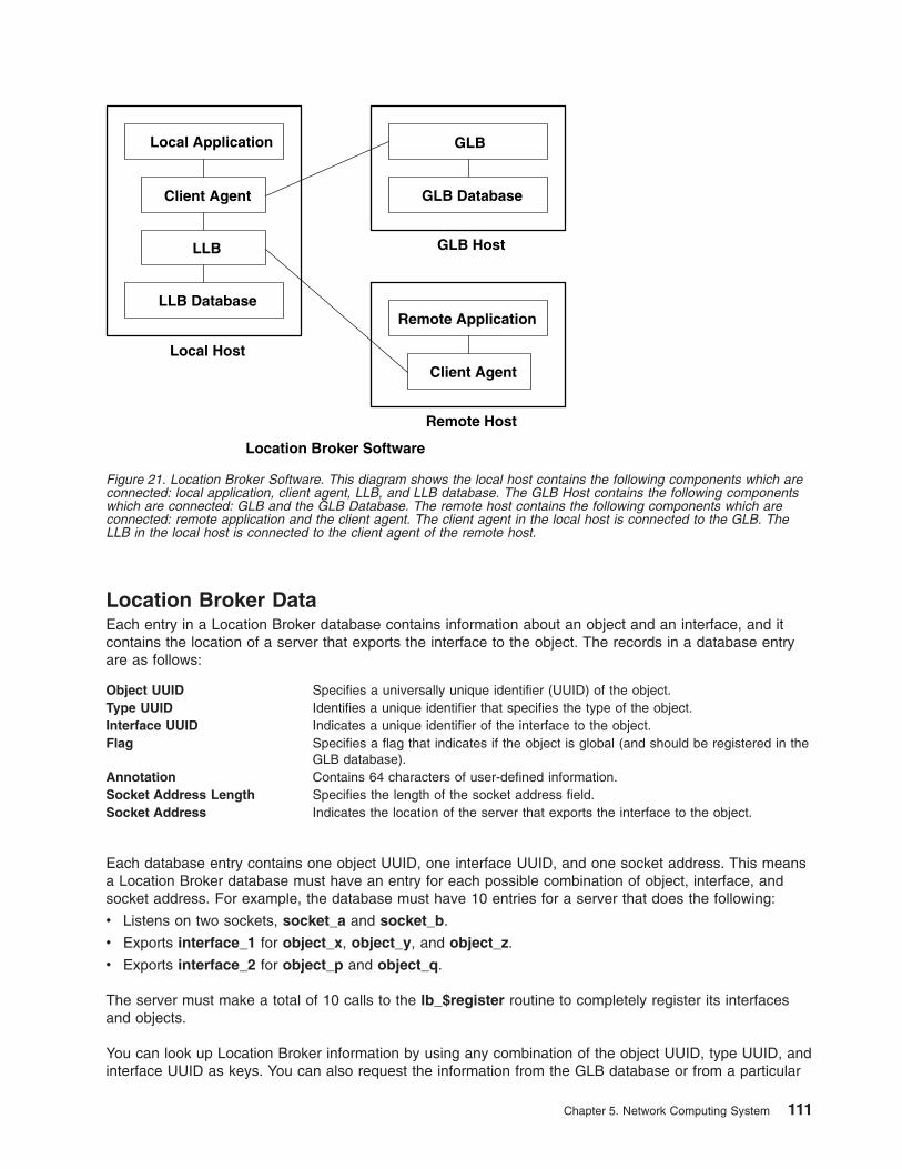
Location Broker Data
Each entry in a Location Broker database contains information about an object and an interface, and it
contains the location of a server that exports the interface to the object. The records in a database entry
are as follows:
Object UUID Specifies a universally unique identifier (UUID) of the object.
Type UUID Identifies a unique identifier that specifies the type of the object.
Interface UUID Indicates a unique identifier of the interface to the object.
Flag Specifies a flag that indicates if the object is global (and should be registered in the
GLB database).
Annotation Contains 64 characters of user-defined information.
Socket Address Length Specifies the length of the socket address field.
Socket Address Indicates the location of the server that exports the interface to the object.
Each database entry contains one object UUID, one interface UUID, and one socket address. This means
a Location Broker database must have an entry for each possible combination of object, interface, and
socket address. For example, the database must have 10 entries for a server that does the following:
v Listens on two sockets, socket_a and socket_b.
v Exports interface_1 for object_x, object_y, and object_z.
v Exports interface_2 for object_p and object_q.
The server must make a total of 10 calls to the lb_$register routine to completely register its interfaces
and objects.
You can look up Location Broker information by using any combination of the object UUID, type UUID, and
interface UUID as keys. You can also request the information from the GLB database or from a particular
LLB Database
Local Host
GLB
GLB Database
Remote Application
Client Agent
Remote Host
GLB HostLLB
Client Agent
Local Application
Location Broker Software
Figure 21. Location Broker Software. This diagram shows the local host contains the following components which are
connected: local application, client agent, LLB, and LLB database. The GLB Host contains the following components
which are connected: GLB and the GLB Database. The remote host contains the following components which are
connected: remote application and the client agent. The client agent in the local host is connected to the GLB. The
LLB in the local host is connected to the client agent of the remote host.
Chapter 5. Network Computing System 111
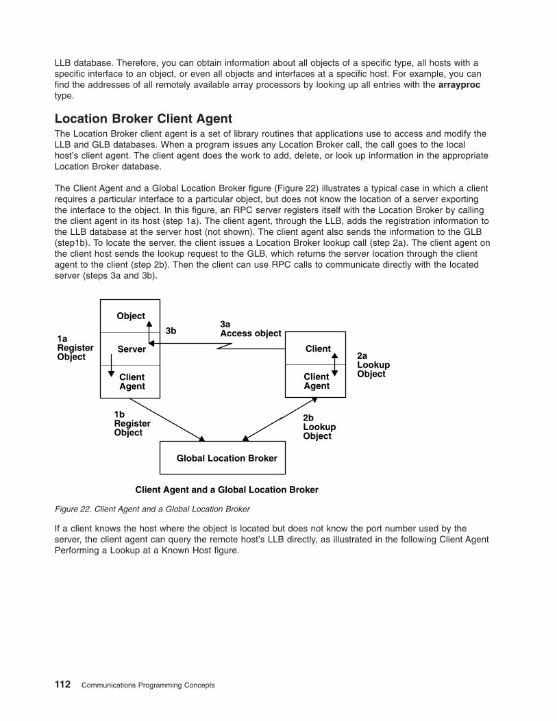
LLB database. Therefore, you can obtain information about all objects of a specific type, all hosts with a
specific interface to an object, or even all objects and interfaces at a specific host. For example, you can
find the addresses of all remotely available array processors by looking up all entries with the arrayproc
type.
Location Broker Client Agent
The Location Broker client agent is a set of library routines that applications use to access and modify the
LLB and GLB databases. When a program issues any Location Broker call, the call goes to the local
host’s client agent. The client agent does the work to add, delete, or look up information in the appropriate
Location Broker database.
The Client Agent and a Global Location Broker figure (Figure 22) illustrates a typical case in which a client
requires a particular interface to a particular object, but does not know the location of a server exporting
the interface to the object. In this figure, an RPC server registers itself with the Location Broker by calling
the client agent in its host (step 1a). The client agent, through the LLB, adds the registration information to
the LLB database at the server host (not shown). The client agent also sends the information to the GLB
(step1b). To locate the server, the client issues a Location Broker lookup call (step 2a). The client agent on
the client host sends the lookup request to the GLB, which returns the server location through the client
agent to the client (step 2b). Then the client can use RPC calls to communicate directly with the located
server (steps 3a and 3b).
If a client knows the host where the object is located but does not know the port number used by the
server, the client agent can query the remote host’s LLB directly, as illustrated in the following Client Agent
Performing a Lookup at a Known Host figure.
1bRegisterObject
ClientAgent
Server
Object
1aRegisterObject
Global Location Broker
3aAccess object
Client2aLookupObjectClient
Agent
2bLookupObject
3b
Client Agent and a Global Location Broker
Figure 22. Client Agent and a Global Location Broker
112 Communications Programming Concepts
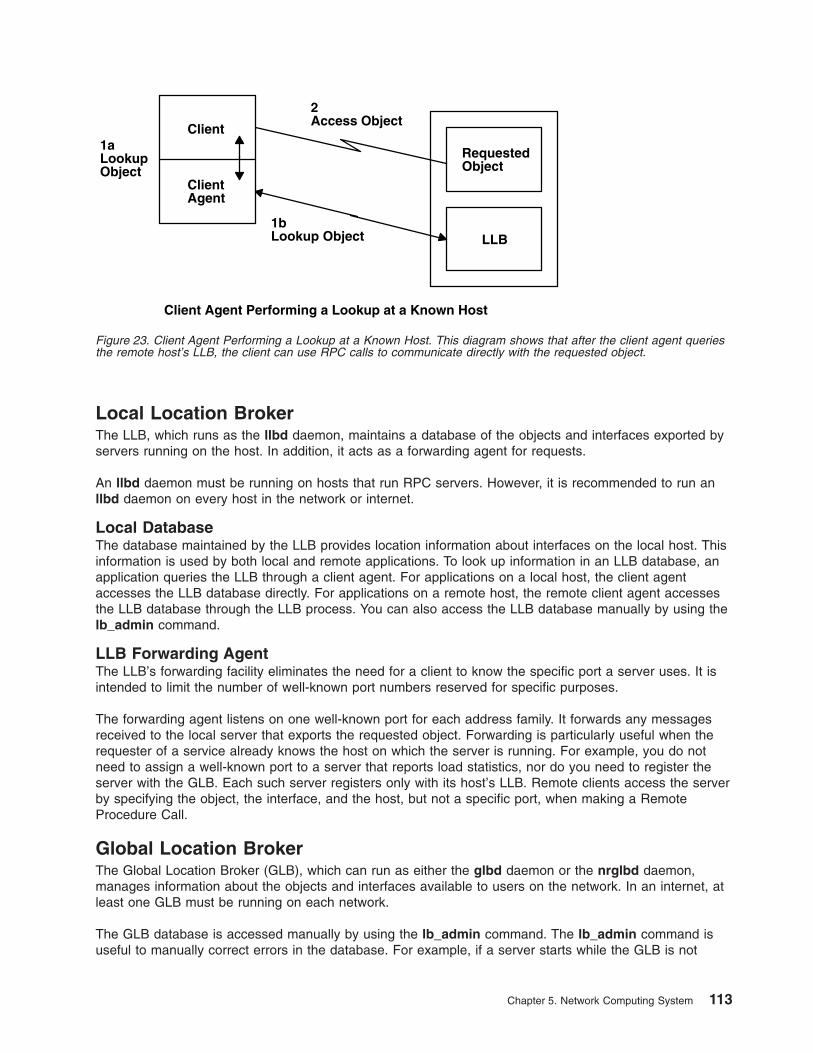
Local Location Broker
The LLB, which runs as the llbd daemon, maintains a database of the objects and interfaces exported by
servers running on the host. In addition, it acts as a forwarding agent for requests.
An llbd daemon must be running on hosts that run RPC servers. However, it is recommended to run an
llbd daemon on every host in the network or internet.
Local Database
The database maintained by the LLB provides location information about interfaces on the local host. This
information is used by both local and remote applications. To look up information in an LLB database, an
application queries the LLB through a client agent. For applications on a local host, the client agent
accesses the LLB database directly. For applications on a remote host, the remote client agent accesses
the LLB database through the LLB process. You can also access the LLB database manually by using the
lb_admin command.
LLB Forwarding Agent
The LLB’s forwarding facility eliminates the need for a client to know the specific port a server uses. It is
intended to limit the number of well-known port numbers reserved for specific purposes.
The forwarding agent listens on one well-known port for each address family. It forwards any messages
received to the local server that exports the requested object. Forwarding is particularly useful when the
requester of a service already knows the host on which the server is running. For example, you do not
need to assign a well-known port to a server that reports load statistics, nor do you need to register the
server with the GLB. Each such server registers only with its host’s LLB. Remote clients access the server
by specifying the object, the interface, and the host, but not a specific port, when making a Remote
Procedure Call.
Global Location Broker
The Global Location Broker (GLB), which can run as either the glbd daemon or the nrglbd daemon,
manages information about the objects and interfaces available to users on the network. In an internet, at
least one GLB must be running on each network.
The GLB database is accessed manually by using the lb_admin command. The lb_admin command is
useful to manually correct errors in the database. For example, if a server starts while the GLB is not
2Access Object
1bLookup Object LLB
RequestedObject
1aLookupObject
Client
ClientAgent
Client Agent Performing a Lookup at a Known Host
Figure 23. Client Agent Performing a Lookup at a Known Host. This diagram shows that after the client agent queries
the remote host’s LLB, the client can use RPC calls to communicate directly with the requested object.
Chapter 5. Network Computing System 113

running, you can manually enter the information for the server in the GLB database. Similarly, if a server
terminates abnormally without unregistering itself, you can use the lb_admin command to manually
remove its entry from the GLB database.
114 Communications Programming Concepts
Chapter 6. Network Information Services (NIS and NIS+)
The NFS Network Information Services (NIS) is a distributed database system used to distribute system
information on networked hosts. NIS+ expands the network name service provided by NIS by enabling you
to store information about workstation addresses, security information, mail information, Ethernet
interfaces, and network services in central locations where all workstations on a network can access it.
This chapter lists technical reference sources for programming NIS and NIS+ (See “List of NIS and NIS+
Programming References”). See AIX 5L Version 5.3 Network Information Services (NIS and NIS+) Guide
for more information.
List of NIS and NIS+ Programming References
The list of Network Information Service (NIS and NIS+) references includes:
v “Subroutines”
v “Files”
v “NIS+ Commands” on page 116
v “NIS+ Tables” on page 116
v “NIS+ APIs” on page 117
See List of NIS Commands in AIX 5L Version 5.3 Network Information Services (NIS and NIS+) Guide for
information about NIS commands and daemons.
Subroutines
yp_all Transfers all of the key-value pairs from the NIS server to the client as the entire
map.
yp_bind Calls the ypbind daemon directly for processes that use backup strategies when
NIS is not available.
yp_first Returns the first key-value pair from the named NIS map in the named domain.
yp_get_default_domain Gets the default domain of the node.
yp_master Returns the machine name of the NIS master server for a map.
yp_match Searches for the value associated with a key.
yp_next Returns each subsequent value it finds in the named NIS map until it reaches the
end of the list.
yp_order Returns the order number for an NIS map that identifies when the map was built.
yp_unbind Manages socket descriptors for processes that access multiple domains.
yp_update Makes changes to the NIS map.
yperr_string Returns a pointer to an error message string.
ypprot_err Takes an NIS protocol error code as input and returns an error code to be used as
input to a yperr_string subroutine.
Files
ethers Lists Ethernet addresses of hosts on the network.
netgroup Lists the groups of users on the network.
netmasks Lists network masks used to implement Internet Protocol standard subnetting.
publickey Stores public or secret keys from NIS maps.
updaters Contains a makefile for updating NIS maps.
xtab Lists directories that are currently exported.
© Copyright IBM Corp. 1994, 2005 115
NIS+ Commands
Command Description
nisaddcred Creates credentials for NIS+ principals and stores them in the cred table.
nisaddent Adds information from /etc files or NIS maps into NIS+ tables.
niscat Displays the contents of NIS+ tables.
nischgrp Changes the group owner of an NIS+ object.
nischmod Changes an object’s access rights.
nischown Changes the owner of an NIS+ object.
nischttl Changes an NIS+ object’s time-to-live value.
nisdefaults Lists an NIS+ object’s default values: domain name, group name, workstation name, NIS+
principal name, access rights, directory search path, and time-to-live.
nisgrep Searches for entries in an NIS+ table.
nisgrpadm Creates or destroys an NIS+ group, or displays a list of its members. Also adds members to a
group, removes them, or tests them for membership in the group.
nisinit Initializes an NIS+ client or server.
nisln Creates a symbolic link between two NIS+ objects.
nisls Lists the contents of an NIS+ directory.
nismatch Searches for entries in an NIS+ table.
nismkdir Creates an NIS+ directory and specifies its master and replica servers.
nismkuser Creates an NIS+ user.
nispasswd Not supported in AIX. Use the passwd command.
nisrm Removes NIS+ objects (except directories) from the namespace.
nisrmdir Removes NIS+ directories and replicas from the namespace.
nisrmuser Removes an NIS+ user.
nissetup Creates org_dir and groups_dir directories and a complete set of (unpopulated) NIS+ tables for
an NIS+ domain.
nisshowcache Lists the contents of the NIS+ shared cache maintained by the NIS+ cache manager.
nistbladm Creates or deletes NIS+ tables, and adds, modifies or deletes entries in an NIS+ table.
nisupdkeys Updates the public keys stored in an NIS+ object.
passwd Changes password information stored in the NIS+ passwd table.
NIS+ Tables
Table Information in the Table
hosts Network address and host name of every workstation in the domain
bootparams Location of the root, swap, and dump partition of every diskless client in the domain
passwd Password information about every user in the domain.
cred Credentials for principals who belong to the domain
group The group name, group password, group ID, and members of every UNIX group in the
domain
netgroup The netgroups to which workstations and users in the domain may belong
mail_aliases Information about the mail aliases of users in the domain
timezone The time zone of every workstation in the domain
networks The networks in the domain and their canonical names
netmasks The networks in the domain and their associated netmasks
ethers The Ethernet address of every workstation in the domain
services The names of IP services used in the domain and their port numbers
protocols The list of IP protocols used in the domain
RPC The RPC program numbers for RPC services available in the domain
auto_home The location of all user’s home directories in the domain
auto_master Automounter map information
sendmailvars The mail domain
client_info Information about NIS+ clients
116 Communications Programming Concepts
NIS+ APIs
The NIS+ application program interface (API) functions include:
v nis_add_entry
v nis_first_entry
v nis_list
v nis_local_directory
v nis_lookup
v nis_modify_entry
v nis_next_entry
v nis_perror
v nis_remove_entry
v nis_sperror
Chapter 6. Network Information Services (NIS and NIS+) 117

118 Communications Programming Concepts
Chapter 7. Network Management
The Network Management facility meets programming needs by managing system networks through the
use of Simple Network Management Protocol (SNMP) by network hosts to exchange information.
The following topics are discussed in this chapter:
v “Simple Network Management Protocol”
v “Management Information Base” on page 120
v “Terminology Related to Management Information Base Variables” on page 122
v “Working with Management Information Base Variables” on page 123
v “Management Information Base Database” on page 123
v “How a Manager Functions” on page 125
v “How an Agent Functions” on page 125
v “List of SNMP Agent Programming References” on page 127
v “SMUX Error Logging Subroutines Examples” on page 128
Simple Network Management Protocol
The Simple Network Management Protocol (SNMP) is used by network hosts to exchange information in
the management of networks. SNMP is defined in several Requests for Comments (RFCs) available from
the Network Information Center at SRI International, Menlo Park, California.
The following RFCs define SNMP:
RFC 1155 Structure and Identification of Management Information for TCP/IP-based Internets
RFC 1157 A Simple Network Management Protocol (SNMP)
RFC 1213 Management Information Base for Network Management of TCP/IP-based internets: MIB-II
RFC 1227 Simple Network Management Protocol (SNMP) single multiplexer (SMUX) protocol and Management
Information Base (MIB)
RFC 1229 Extensions to the Generic-Interface Management Information Base (MIB)
RFC 1231 IEEE 802.5 Token Ring Management Information Base (MIB)
RFC 1398 Definitions of Managed Objects for the Ethernet-like Interface Types
RFC 1512 FDDI Management Information Base (MIB)
RFC 1514 Host Resources Management Information Base (MIB)
RFC 1592 Simple Network Management Protocol Distributed Protocol Interface Version 2.0
RFC 1907 Management Information Base for Version 2 of the Simple Network Management Protocol (SNMPv2)
RFC 2572 Message Processing and Dispatching for the Simple Network Management Protocol (SNMP)
RFC 2573 SNMP Applications
RFC 2574 User-based Security Model (USM) for version 3 of the Simple Network Management Protocol
(SNMPv3)
RFC 2575 View-based Access Control Model (VACM) for the Simple Network Management Protocol (SNMP)
SNMP network management is based on the familiar client-server model that is widely used in
Transmission Control Protocol/Internet Protocol (TCP/IP)-based network applications. Each managed host
runs a process called an agent. The agent is a server process that maintains the MIB database for the
host. Hosts that are involved in network management decision-making may run a process called a
manager. A manager is a client application that generates requests for MIB information and processes
responses. In addition, a manager may send requests to agent servers to modify MIB information.
© Copyright IBM Corp. 1994, 2005 119
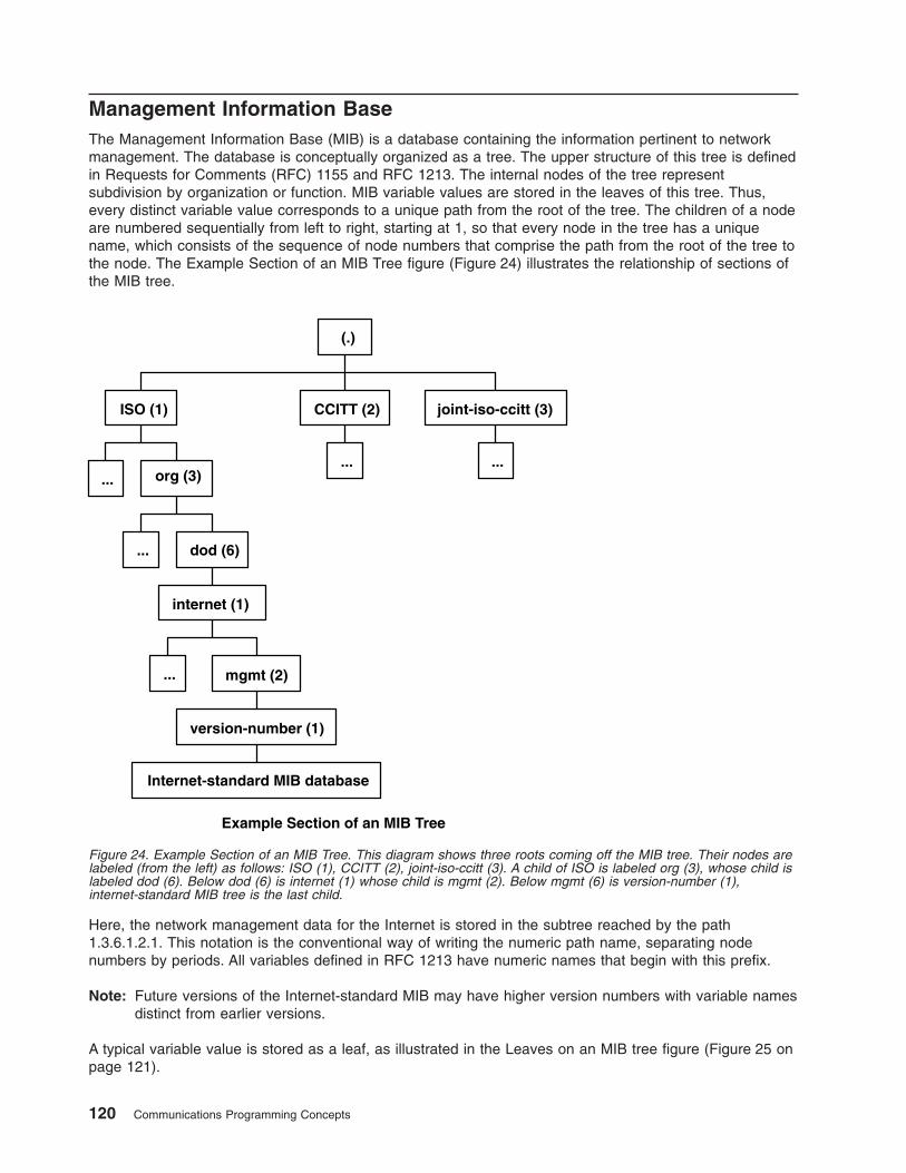
Management Information Base
The Management Information Base (MIB) is a database containing the information pertinent to network
management. The database is conceptually organized as a tree. The upper structure of this tree is defined
in Requests for Comments (RFC) 1155 and RFC 1213. The internal nodes of the tree represent
subdivision by organization or function. MIB variable values are stored in the leaves of this tree. Thus,
every distinct variable value corresponds to a unique path from the root of the tree. The children of a node
are numbered sequentially from left to right, starting at 1, so that every node in the tree has a unique
name, which consists of the sequence of node numbers that comprise the path from the root of the tree to
the node. The Example Section of an MIB Tree figure (Figure 24) illustrates the relationship of sections of
the MIB tree.
Here, the network management data for the Internet is stored in the subtree reached by the path
1.3.6.1.2.1. This notation is the conventional way of writing the numeric path name, separating node
numbers by periods. All variables defined in RFC 1213 have numeric names that begin with this prefix.
Note: Future versions of the Internet-standard MIB may have higher version numbers with variable names
distinct from earlier versions.
A typical variable value is stored as a leaf, as illustrated in the Leaves on an MIB tree figure (Figure 25 on
page 121).
(.)
ISO (1) CCITT (2) joint-iso-ccitt (3)
org (3)
dod (6)
internet (1)
mgmt (2)
Internet-standard MIB database
version-number (1)
...
...
...
... ...
Example Section of an MIB Tree
Figure 24. Example Section of an MIB Tree. This diagram shows three roots coming off the MIB tree. Their nodes are
labeled (from the left) as follows: ISO (1), CCITT (2), joint-iso-ccitt (3). A child of ISO is labeled org (3), whose child is
labeled dod (6). Below dod (6) is internet (1) whose child is mgmt (2). Below mgmt (6) is version-number (1),
internet-standard MIB tree is the last child.
120 Communications Programming Concepts
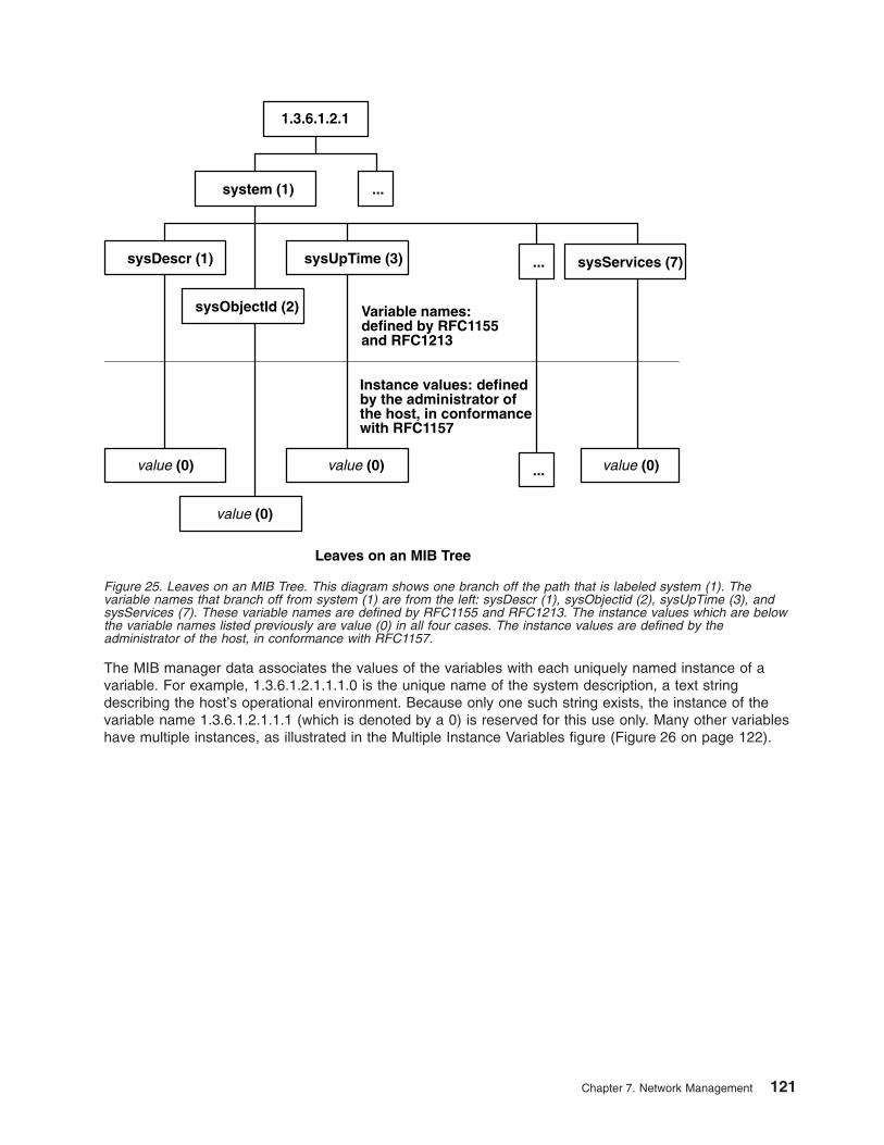
The MIB manager data associates the values of the variables with each uniquely named instance of a
variable. For example, 1.3.6.1.2.1.1.1.0 is the unique name of the system description, a text string
describing the host’s operational environment. Because only one such string exists, the instance of the
variable name 1.3.6.1.2.1.1.1 (which is denoted by a 0) is reserved for this use only. Many other variables
have multiple instances, as illustrated in the Multiple Instance Variables figure (Figure 26 on page 122).
1.3.6.1.2.1
system (1)
sysObjectId (2)
sysUpTime (3)
(0)
Variable names:defined by RFC1155and RFC1213
Instance values: definedby the administrator ofthe host, in conformancewith RFC1157
sysDescr (1)
...
value
(0)value
(0)value
...
...
sysServices (7)
(0)value
Leaves on an MIB Tree
Figure 25. Leaves on an MIB Tree. This diagram shows one branch off the path that is labeled system (1). The
variable names that branch off from system (1) are from the left: sysDescr (1), sysObjectid (2), sysUpTime (3), and
sysServices (7). These variable names are defined by RFC1155 and RFC1213. The instance values which are below
the variable names listed previously are value (0) in all four cases. The instance values are defined by the
administrator of the host, in conformance with RFC1157.
Chapter 7. Network Management 121
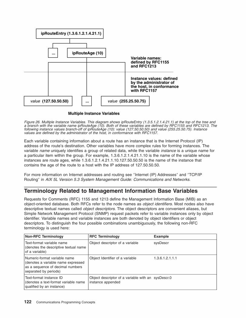
Each variable containing information about a route has an instance that is the Internet Protocol (IP)
address of the route’s destination. Other variables have more complex rules for forming instances. The
variable name uniquely identifies a group of related data, while the variable instance is a unique name for
a particular item within the group. For example, 1.3.6.1.2.1.4.21.1.10 is the name of the variable whose
instances are route ages, while 1.3.6.1.2.1.4.21.1.10.127.50.50.50 is the name of the instance that
contains the age of the route to a host with the IP address of 127.50.50.50.
For more information on Internet addresses and routing see ″Internet (IP) Addresses″ and ″TCP/IP
Routing″ in AIX 5L Version 5.3 System Management Guide: Communications and Networks.
Terminology Related to Management Information Base Variables
Requests for Comments (RFC) 1155 and 1213 define the Management Information Base (MIB) as an
object-oriented database. Both RFCs refer to the node names as object identifiers. Most nodes also have
descriptive textual names called object descriptors. The object descriptors are convenient aliases, but
Simple Network Management Protocol (SNMP) request packets refer to variable instances only by object
identifier. Variable names and variable instances are both denoted by object identifiers or object
descriptors. To distinguish the four possible combinations unambiguously, the following non-RFC
terminology is used here:
Non-RFC Terminology RFC Terminology Example
Text-format variable name
(denotes the descriptive textual name
of a variable)
Object descriptor of a variable sysDescr
Numeric-format variable name
(denotes a variable name expressed
as a sequence of decimal numbers
separated by periods)
Object Identifier of a variable 1.3.6.1.2.1.1.1
Text-format instance ID
(denotes a text-format variable name
qualified by an instance)
Object descriptor of a variable with an
instance appended
sysDescr.0
ipRouteEntry (1.3.6.1.2.1.4.21.1)
ipRouteAge (10)
(127.50.50.50) (255.25.50.75)
Variable names:defined by RFC1155and RFC1213
Instance values: definedby the administrator ofthe host, in conformancewith RFC1157
...
... valuevalue
Multiple Instance Variables
Figure 26. Multiple Instance Variables. This diagram shows ipRouteEntry (1.3.5.1.2.1.4.21.1) at the top of the tree and
a branch with the variable name ipRouteAge (10). Both of these variables are defined by RFC1155 and RFC1213. The
following instance values branch-off of ipRouteAge (10): value (127.50.50.50) and value (255.25.50.75). Instance
values are defined by the administrator of the host, in conformance with RFC1157.
122 Communications Programming Concepts
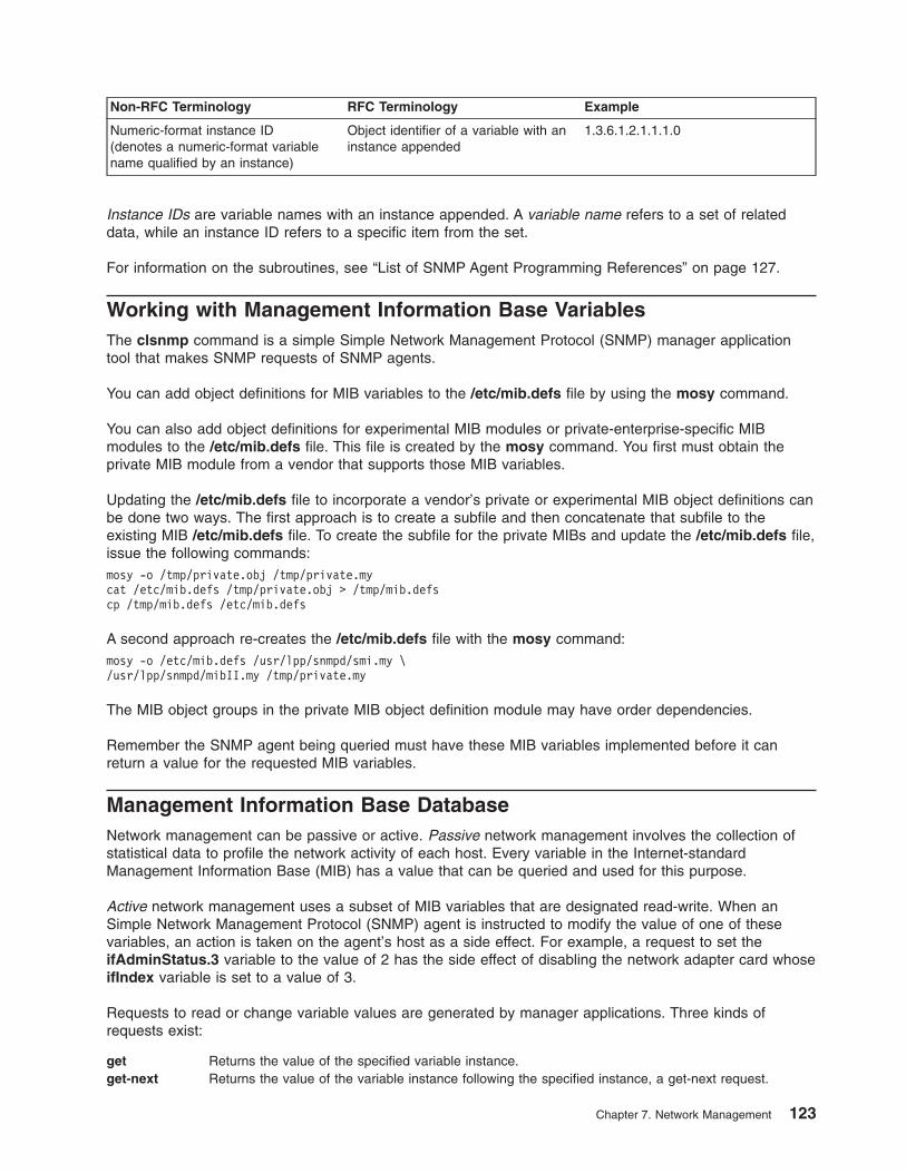
Non-RFC Terminology RFC Terminology Example
Numeric-format instance ID
(denotes a numeric-format variable
name qualified by an instance)
Object identifier of a variable with an
instance appended
1.3.6.1.2.1.1.1.0
Instance IDs are variable names with an instance appended. A variable name refers to a set of related
data, while an instance ID refers to a specific item from the set.
For information on the subroutines, see “List of SNMP Agent Programming References” on page 127.
Working with Management Information Base Variables
The clsnmp command is a simple Simple Network Management Protocol (SNMP) manager application
tool that makes SNMP requests of SNMP agents.
You can add object definitions for MIB variables to the /etc/mib.defs file by using the mosy command.
You can also add object definitions for experimental MIB modules or private-enterprise-specific MIB
modules to the /etc/mib.defs file. This file is created by the mosy command. You first must obtain the
private MIB module from a vendor that supports those MIB variables.
Updating the /etc/mib.defs file to incorporate a vendor’s private or experimental MIB object definitions can
be done two ways. The first approach is to create a subfile and then concatenate that subfile to the
existing MIB /etc/mib.defs file. To create the subfile for the private MIBs and update the /etc/mib.defs file,
issue the following commands:
mosy -o /tmp/private.obj /tmp/private.my
cat /etc/mib.defs /tmp/private.obj > /tmp/mib.defs
cp /tmp/mib.defs /etc/mib.defs
A second approach re-creates the /etc/mib.defs file with the mosy command:
mosy -o /etc/mib.defs /usr/lpp/snmpd/smi.my \
/usr/lpp/snmpd/mibII.my /tmp/private.my
The MIB object groups in the private MIB object definition module may have order dependencies.
Remember the SNMP agent being queried must have these MIB variables implemented before it can
return a value for the requested MIB variables.
Management Information Base Database
Network management can be passive or active. Passive network management involves the collection of
statistical data to profile the network activity of each host. Every variable in the Internet-standard
Management Information Base (MIB) has a value that can be queried and used for this purpose.
Active network management uses a subset of MIB variables that are designated read-write. When an
Simple Network Management Protocol (SNMP) agent is instructed to modify the value of one of these
variables, an action is taken on the agent’s host as a side effect. For example, a request to set the
ifAdminStatus.3 variable to the value of 2 has the side effect of disabling the network adapter card whose
ifIndex variable is set to a value of 3.
Requests to read or change variable values are generated by manager applications. Three kinds of
requests exist:
get Returns the value of the specified variable instance.
get-next Returns the value of the variable instance following the specified instance, a get-next request.
Chapter 7. Network Management 123
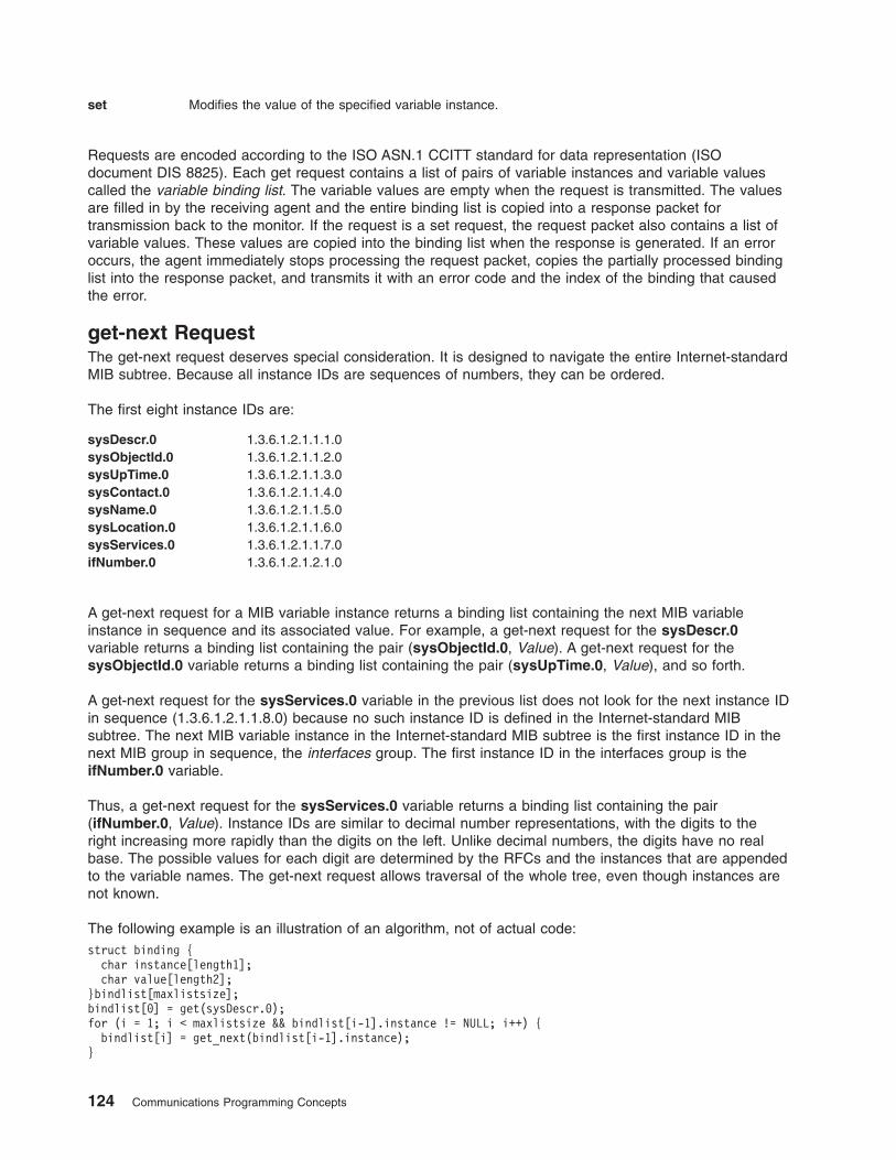
set Modifies the value of the specified variable instance.
Requests are encoded according to the ISO ASN.1 CCITT standard for data representation (ISO
document DIS 8825). Each get request contains a list of pairs of variable instances and variable values
called the variable binding list. The variable values are empty when the request is transmitted. The values
are filled in by the receiving agent and the entire binding list is copied into a response packet for
transmission back to the monitor. If the request is a set request, the request packet also contains a list of
variable values. These values are copied into the binding list when the response is generated. If an error
occurs, the agent immediately stops processing the request packet, copies the partially processed binding
list into the response packet, and transmits it with an error code and the index of the binding that caused
the error.
get-next Request
The get-next request deserves special consideration. It is designed to navigate the entire Internet-standard
MIB subtree. Because all instance IDs are sequences of numbers, they can be ordered.
The first eight instance IDs are:
sysDescr.0 1.3.6.1.2.1.1.1.0
sysObjectId.0 1.3.6.1.2.1.1.2.0
sysUpTime.0 1.3.6.1.2.1.1.3.0
sysContact.0 1.3.6.1.2.1.1.4.0
sysName.0 1.3.6.1.2.1.1.5.0
sysLocation.0 1.3.6.1.2.1.1.6.0
sysServices.0 1.3.6.1.2.1.1.7.0
ifNumber.0 1.3.6.1.2.1.2.1.0
A get-next request for a MIB variable instance returns a binding list containing the next MIB variable
instance in sequence and its associated value. For example, a get-next request for the sysDescr.0
variable returns a binding list containing the pair (sysObjectId.0, Value). A get-next request for the
sysObjectId.0 variable returns a binding list containing the pair (sysUpTime.0, Value), and so forth.
A get-next request for the sysServices.0 variable in the previous list does not look for the next instance ID
in sequence (1.3.6.1.2.1.1.8.0) because no such instance ID is defined in the Internet-standard MIB
subtree. The next MIB variable instance in the Internet-standard MIB subtree is the first instance ID in the
next MIB group in sequence, the interfaces group. The first instance ID in the interfaces group is the
ifNumber.0 variable.
Thus, a get-next request for the sysServices.0 variable returns a binding list containing the pair
(ifNumber.0, Value). Instance IDs are similar to decimal number representations, with the digits to the
right increasing more rapidly than the digits on the left. Unlike decimal numbers, the digits have no real
base. The possible values for each digit are determined by the RFCs and the instances that are appended
to the variable names. The get-next request allows traversal of the whole tree, even though instances are
not known.
The following example is an illustration of an algorithm, not of actual code:
struct binding {
char instance[length1];
char value[length2];
}bindlist[maxlistsize];
bindlist[0] = get(sysDescr.0);
for (i = 1; i < maxlistsize && bindlist[i-1].instance != NULL; i++) {
bindlist[i] = get_next(bindlist[i-1].instance);
}
124 Communications Programming Concepts
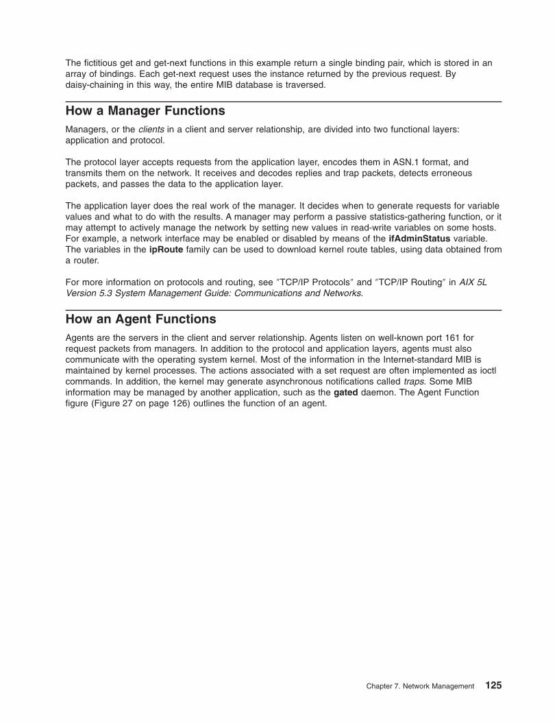
The fictitious get and get-next functions in this example return a single binding pair, which is stored in an
array of bindings. Each get-next request uses the instance returned by the previous request. By
daisy-chaining in this way, the entire MIB database is traversed.
How a Manager Functions
Managers, or the clients in a client and server relationship, are divided into two functional layers:
application and protocol.
The protocol layer accepts requests from the application layer, encodes them in ASN.1 format, and
transmits them on the network. It receives and decodes replies and trap packets, detects erroneous
packets, and passes the data to the application layer.
The application layer does the real work of the manager. It decides when to generate requests for variable
values and what to do with the results. A manager may perform a passive statistics-gathering function, or it
may attempt to actively manage the network by setting new values in read-write variables on some hosts.
For example, a network interface may be enabled or disabled by means of the ifAdminStatus variable.
The variables in the ipRoute family can be used to download kernel route tables, using data obtained from
a router.
For more information on protocols and routing, see ″TCP/IP Protocols″ and ″TCP/IP Routing″ in AIX 5L
Version 5.3 System Management Guide: Communications and Networks.
How an Agent Functions
Agents are the servers in the client and server relationship. Agents listen on well-known port 161 for
request packets from managers. In addition to the protocol and application layers, agents must also
communicate with the operating system kernel. Most of the information in the Internet-standard MIB is
maintained by kernel processes. The actions associated with a set request are often implemented as ioctl
commands. In addition, the kernel may generate asynchronous notifications called traps. Some MIB
information may be managed by another application, such as the gated daemon. The Agent Function
figure (Figure 27 on page 126) outlines the function of an agent.
Chapter 7. Network Management 125
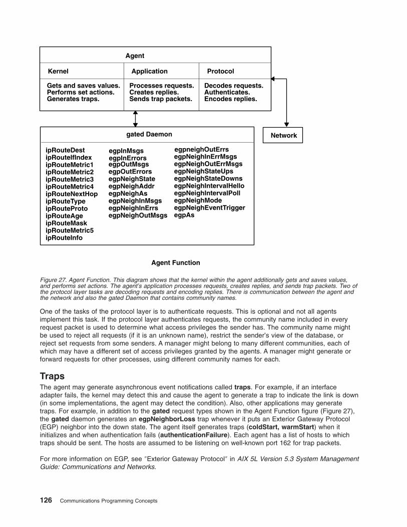
One of the tasks of the protocol layer is to authenticate requests. This is optional and not all agents
implement this task. If the protocol layer authenticates requests, the community name included in every
request packet is used to determine what access privileges the sender has. The community name might
be used to reject all requests (if it is an unknown name), restrict the sender’s view of the database, or
reject set requests from some senders. A manager might belong to many different communities, each of
which may have a different set of access privileges granted by the agents. A manager might generate or
forward requests for other processes, using different community names for each.
Traps
The agent may generate asynchronous event notifications called traps. For example, if an interface
adapter fails, the kernel may detect this and cause the agent to generate a trap to indicate the link is down
(in some implementations, the agent may detect the condition). Also, other applications may generate
traps. For example, in addition to the gated request types shown in the Agent Function figure (Figure 27),
the gated daemon generates an egpNeighborLoss trap whenever it puts an Exterior Gateway Protocol
(EGP) neighbor into the down state. The agent itself generates traps (coldStart, warmStart) when it
initializes and when authentication fails (authenticationFailure). Each agent has a list of hosts to which
traps should be sent. The hosts are assumed to be listening on well-known port 162 for trap packets.
For more information on EGP, see ″Exterior Gateway Protocol″ in AIX 5L Version 5.3 System Management
Guide: Communications and Networks.
Agent
Application
Processes requests.Creates replies.Sends trap packets.
Protocol
Decodes requests.Authenticates.Encodes replies.
Network
Kernel
Gets and saves values.Performs set actions.Generates traps.
gated Daemon
egpInMsgsegpInErrorsegpOutMsgsegpOutErrorsegpNeighStateegpNeighAddregpNeighAsegpNeighInMsgsegpNeighInErrsegpNeighOutMsgs
egpneighOutErrsegpNeighInErrMsgsegpNeighOutErrMsgsegpNeighStateUpsegpNeighStateDownsegpNeighIntervalHelloegpNeighIntervalPollegpNeighModeegpNeighEventTriggeregpAs
ipRouteDestipRouteIfIndexipRouteMetric1ipRouteMetric2ipRouteMetric3ipRouteMetric4ipRouteNextHopipRouteTypeipRouteProtoipRouteAgeipRouteMaskipRouteMetric5ipRouteInfo
Agent Function
Figure 27. Agent Function. This diagram shows that the kernel within the agent additionally gets and saves values,
and performs set actions. The agent’s application processes requests, creates replies, and sends trap packets. Two of
the protocol layer tasks are decoding requests and encoding replies. There is communication between the agent and
the network and also the gated Daemon that contains community names.
126 Communications Programming Concepts
List of SNMP Agent Programming References
The list of Simple Network Management Protocol (SNMP) programming references includes:
v “Programming Commands”
v “Files and File Formats”
v “SMUX Subroutines”
Refer to the AIX 5L Version 5.3 Commands Reference for information about the system commands.
Programming Commands
mosy Converts the ASN.1 definitions of Structure and Identification of Management Information (SMI) and
Management Information Base (MIB) modules into an object definition file for the clsnmp command.
clsnmp Requests or modifies values of MIB variables managed by an SNMP agent.
Files and File Formats
mib.defs Defines the MIB variables the SNMP agent should recognize and handle. The format of the
/etc/mib.defs file is required by the snmpinfo command.
mibII.my Defines the ASN.1 definitions for the MIB variables as defined in RFC 1213.
smi.my Defines the ASN.1 definitions by which the SMI is defined as in RFC 1155.
snmpd.conf Defines a sample configuration file for the snmpd agent.
ethernet.my Defines the ASN.1 definitions for the MIB variables defined in RFC 1398.
fddi.my Defines the ASN.1 definitions for the MIB variables defined in RFC 1512.
generic.my Defines the ASN.1 definitions for the MIB variables defined in RFC 1229.
ibm.my Defines the ASN.1 definitions for the IBM enterprise section of the MIB tree.
token-ring.my Defines the ASN.1 definitions for the MIB variables defined in RFC 1231.
unix.my Defines the ASN.1 definitions for a set of MIB variables for memory buffer (mbuf) statistics,
SNMP multiplexing (SMUX) peer information, and various other information.
view.my Defines the ASN.1 definitions for the SNMP access list and view tables.
snmpd.peers Defines a sample peers file for the snmpd agent.
SMUX Subroutines
getsmuxEntrybyidentity Retrieves SMUX peers by object identifier.
getsmuxEntrybyname Retrieves SMUX peers by name.
isodetailor Initializes variables for various logging facilities.
_ll_log Reports errors to log files.
ll_dbinit Reports errors to log files.
ll_hdinit Reports errors to log files.
ll_log Reports errors to log files.
o_generic Encodes values retrieved from the MIB into the specified variable binding.
o_igeneric Encodes values retrieved from the MIB into the specified variable binding.
o_integer Encodes values retrieved from the MIB into the specified variable binding.
o_ipaddr Encodes values retrieved from the MIB into the specified variable binding.
o_number Encodes values retrieved from the MIB into the specified variable binding.
o_specific Encodes values retrieved from the MIB into the specified variable binding.
o_string Encodes values retrieved from the MIB into the specified variable binding.
ode2oid Returns a static pointer to the object identifier. If unsuccessful, the NULLOID value
is returned.
oid2ode Takes an object identifier and returns its dot-notation description as a string.
oid2prim Encodes an object identifier structure into a presentation element.
oid_cmp Manipulates the object identifier structure.
Chapter 7. Network Management 127
oid_cpy Manipulates the object identifier structure.
oid_extend Extends the base /usr/lib/libisode.a library subroutines.
oid_free Manipulates the object identifier structure.
oid_normalize Extends and adjusts the values of the object identifier structure entries for the base
/usr/lib/libisode.a library subroutines.
prim2oid Decodes an object identifier from a presentation element.
readobjects Allows an SMUX peer to read the MIB variable structure.
s_generic Sets the value of the MIB variable in the database.
smux_close Ends communication with the SNMP agent.
smux_error Creates a readable string from information found in the smux_errno global
variable.
smux_free_tree Frees the object tree when an SMUX tree is unregistered.
smux_init Initiates the Transmission Control Protocol (TCP) socket that the SMUX agent uses
and clears the basic SMUX data structures.
smux_register Registers a section of the MIB tree with the SNMP agent.
smux_response Sends a response to a SNMP agent.
smux_simple_open Sends the open protocol data unit (PDU) to the SNMP daemon.
smux_trap Allows the SMUX peer to send traps to the SNMP agent.
smux_wait Waits for a message from the SNMP agent.
sprintoid Manipulates the object identifier structure.
str2oid Manipulates the object identifier structure.
text2oid Converts a text string into an object identifier.
text2obj Converts a text string into an object.
text2inst Retrieves instances of variables from a character string.
name2inst Retreives instances of variables from various forms of data.
next2inst Retreives instances of variables from various forms of data.
nextot2inst Retreives instances of variables from various forms of data.
SMUX Error Logging Subroutines Examples
The advise and adios subroutines are example subroutines created to illustrate how the SNMP
multiplexing (SMUX) _ll_log logging subroutine can be used. The adios and advise sample subroutines
are in the unixd.c and sampled.c sample programs.
The adios subroutine exits on a fatal error. This subroutine sends a fatal message to the log file and exits.
If needed, other functionality can be added to the subroutine to help the failing program exit cleanly.
The advise subroutine sends an advisory message to the log. This subroutine allows the programmer to
specify the message logging event type.
adios Sample Subroutine
/* Function: adios
*
* Inputs:
* what - the thing that went wrong
* fmt - the string to be printed in printf format (char*)
* variables - variable needed to fill in the fmt.
*
* Outputs: none
* Returns: none
*
* NOTE: The adios function calls the logging function with the
* variables above and a LLOG_FATAL error code. The function then
* exits with a return code of 1, thereby terminating the sampled
* process.
*/
#ifndef lint
128 Communications Programming Concepts
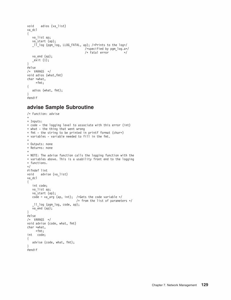
void adios (va_list)
va_dcl
{
va_list ap;
va_start (ap);
_ll_log (pgm_log, LLOG_FATAL, ap); /*Prints to the log*/
/*specified by pgm_log.a*/
/* Fatal error */
va_end (ap);
_exit (1);
}
#else
/* VARAGS */
void adios (what,fmt)
char *what,
*fmt;
{
adios (what, fmt);
}
#endif
advise Sample Subroutine
/* Function: advise
*
* Inputs:
* code - the logging level to associate with this error (int)
* what - the thing that went wrong
* fmt - the string to be printed in printf format (char*)
* variables - variable needed to fill in the fmt.
*
* Outputs: none
* Returns: none
*
* NOTE: The advise function calls the logging function with the
* variables above. This is a usability front end to the logging
* functions.
*/
#ifndef lint
void advise (va_list)
va_dcl
{
int code;
va_list ap;
va_start (ap);
code = va_arg (ap, int); /*Gets the code variable */
/* from the list of parameters */
_ll_log (pgm_log, code, ap);
va_end (ap);
}
#else
/* VARAGS */
void advise (code, what, fmt)
char *what,
*fmt;
int code;
{
advise (code, what, fmt);
}
#endif
Chapter 7. Network Management 129

130 Communications Programming Concepts
Chapter 8. Remote Procedure Call
Remote Procedure Call (RPC) is a protocol that provides the high-level communications paradigm used in
the operating system. RPC presumes the existence of a low-level transport protocol, such as Transmission
Control Protocol/Internet Protocol (TCP/IP) or User Datagram Protocol (UDP), for carrying the message
data between communicating programs. RPC implements a logical client-to-server communications system
designed specifically for the support of network applications.
This chapter provides the following information about programming RPC:
v “RPC Model” on page 132
v “RPC Message Protocol” on page 133
v “RPC Authentication” on page 138
v “RPC Port Mapper Program” on page 144
v “Programming in RPC” on page 146
v “RPC Features” on page 153
v “RPC Language” on page 155
v “rpcgen Protocol Compiler” on page 160
v “List of RPC Programming References” on page 162
The RPC protocol is built on top of the eXternal Data Representation (XDR) protocol, which standardizes
the representation of data in remote communications. XDR converts the parameters and results of each
RPC service provided.
The RPC protocol enables users to work with remote procedures as if the procedures were local. The
remote procedure calls are defined through routines contained in the RPC protocol. Each call message is
matched with a reply message. The RPC protocol is a message-passing protocol that implements other
non-RPC protocols such as batching and broadcasting remote calls. The RPC protocol also supports
callback procedures and the select subroutine on the server side.
A client is a computer or process that accesses the services or resources of another process or computer
on the network. A server is a computer that provides services and resources, and that implements network
services. Each network service is a collection of remote programs. A remote program implements remote
procedures. The procedures, their parameters, and the results are all documented in the specific
program’s protocol.
RPC provides an authentication process that identifies the server and client to each other. RPC includes a
slot for the authentication parameters on every remote procedure call so that the caller can identify itself to
the server. The client package generates and returns authentication parameters. RPC supports various
types of authentication such as the UNIX and Data Encryption Standard (DES) systems.
In RPC, each server supplies a program that is a set of remote service procedures. The combination of a
host address, program number, and procedure number specifies one remote service procedure. In the
RPC model, the client makes a procedure call to send a data packet to the server. When the packet
arrives, the server calls a dispatch routine, performs whatever service is requested, and sends a reply
back to the client. The procedure call then returns to the client.
The RPC interface is generally used to communicate between processes on different workstations in a
network. However, RPC works just as well for communication between different processes on the same
workstation.
The Port Mapper program maps RPC program and version numbers to a transport-specific port number.
The Port Mapper program makes dynamic binding of remote programs possible.
© Copyright IBM Corp. 1994, 2005 131
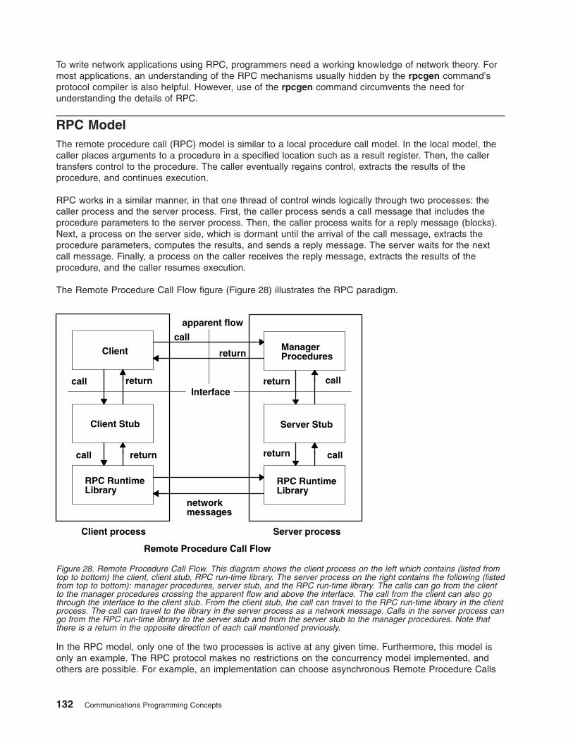
To write network applications using RPC, programmers need a working knowledge of network theory. For
most applications, an understanding of the RPC mechanisms usually hidden by the rpcgen command’s
protocol compiler is also helpful. However, use of the rpcgen command circumvents the need for
understanding the details of RPC.
RPC Model
The remote procedure call (RPC) model is similar to a local procedure call model. In the local model, the
caller places arguments to a procedure in a specified location such as a result register. Then, the caller
transfers control to the procedure. The caller eventually regains control, extracts the results of the
procedure, and continues execution.
RPC works in a similar manner, in that one thread of control winds logically through two processes: the
caller process and the server process. First, the caller process sends a call message that includes the
procedure parameters to the server process. Then, the caller process waits for a reply message (blocks).
Next, a process on the server side, which is dormant until the arrival of the call message, extracts the
procedure parameters, computes the results, and sends a reply message. The server waits for the next
call message. Finally, a process on the caller receives the reply message, extracts the results of the
procedure, and the caller resumes execution.
The Remote Procedure Call Flow figure (Figure 28) illustrates the RPC paradigm.
In the RPC model, only one of the two processes is active at any given time. Furthermore, this model is
only an example. The RPC protocol makes no restrictions on the concurrency model implemented, and
others are possible. For example, an implementation can choose asynchronous Remote Procedure Calls
ManagerProceduresClient
Server StubClient Stub
RPC RuntimeLibrary
return
call
RPC RuntimeLibrary
Interface
Server processClient process
apparent flow
networkmessages
Remote Procedure Call Flow
return returncall call
callreturncall return
Figure 28. Remote Procedure Call Flow. This diagram shows the client process on the left which contains (listed from
top to bottom) the client, client stub, RPC run-time library. The server process on the right contains the following (listed
from top to bottom): manager procedures, server stub, and the RPC run-time library. The calls can go from the client
to the manager procedures crossing the apparent flow and above the interface. The call from the client can also go
through the interface to the client stub. From the client stub, the call can travel to the RPC run-time library in the client
process. The call can travel to the library in the server process as a network message. Calls in the server process can
go from the RPC run-time library to the server stub and from the server stub to the manager procedures. Note that
there is a return in the opposite direction of each call mentioned previously.
132 Communications Programming Concepts
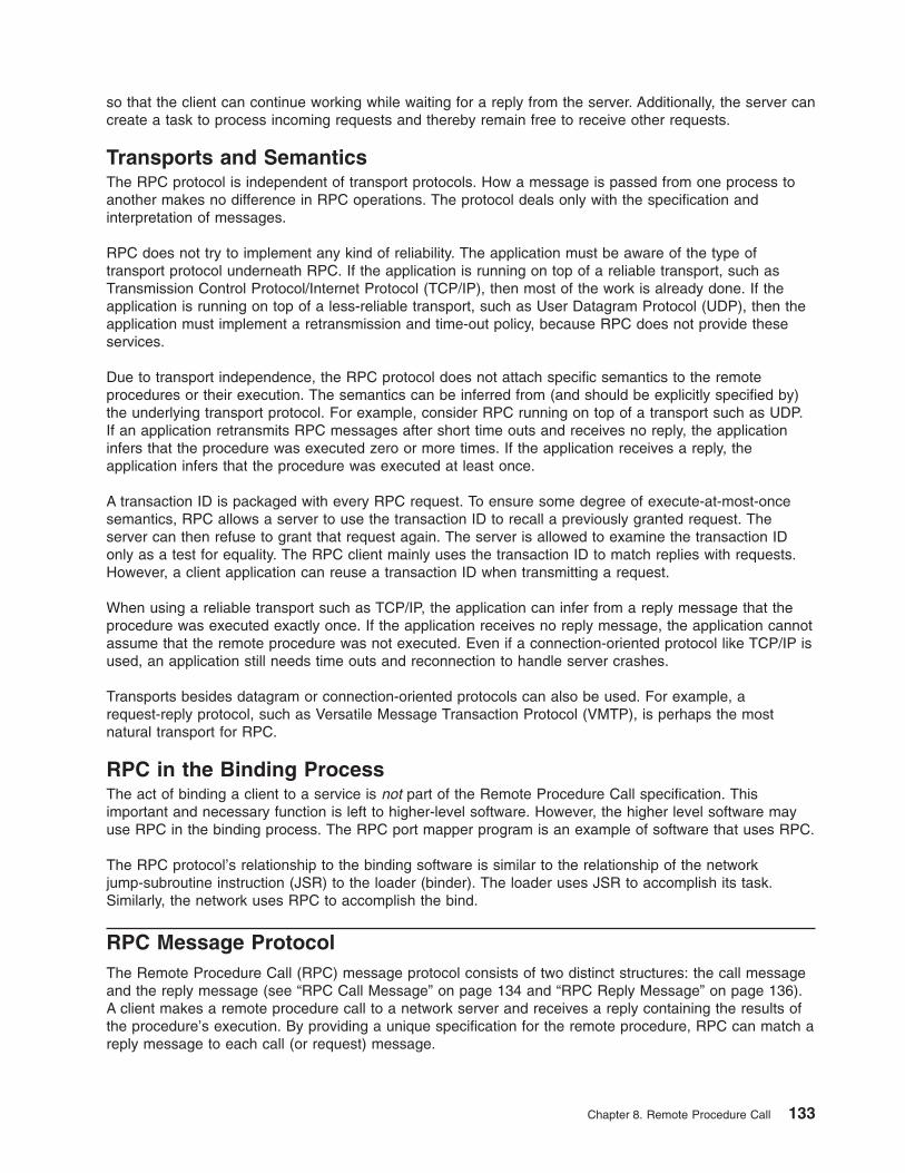
so that the client can continue working while waiting for a reply from the server. Additionally, the server can
create a task to process incoming requests and thereby remain free to receive other requests.
Transports and Semantics
The RPC protocol is independent of transport protocols. How a message is passed from one process to
another makes no difference in RPC operations. The protocol deals only with the specification and
interpretation of messages.
RPC does not try to implement any kind of reliability. The application must be aware of the type of
transport protocol underneath RPC. If the application is running on top of a reliable transport, such as
Transmission Control Protocol/Internet Protocol (TCP/IP), then most of the work is already done. If the
application is running on top of a less-reliable transport, such as User Datagram Protocol (UDP), then the
application must implement a retransmission and time-out policy, because RPC does not provide these
services.
Due to transport independence, the RPC protocol does not attach specific semantics to the remote
procedures or their execution. The semantics can be inferred from (and should be explicitly specified by)
the underlying transport protocol. For example, consider RPC running on top of a transport such as UDP.
If an application retransmits RPC messages after short time outs and receives no reply, the application
infers that the procedure was executed zero or more times. If the application receives a reply, the
application infers that the procedure was executed at least once.
A transaction ID is packaged with every RPC request. To ensure some degree of execute-at-most-once
semantics, RPC allows a server to use the transaction ID to recall a previously granted request. The
server can then refuse to grant that request again. The server is allowed to examine the transaction ID
only as a test for equality. The RPC client mainly uses the transaction ID to match replies with requests.
However, a client application can reuse a transaction ID when transmitting a request.
When using a reliable transport such as TCP/IP, the application can infer from a reply message that the
procedure was executed exactly once. If the application receives no reply message, the application cannot
assume that the remote procedure was not executed. Even if a connection-oriented protocol like TCP/IP is
used, an application still needs time outs and reconnection to handle server crashes.
Transports besides datagram or connection-oriented protocols can also be used. For example, a
request-reply protocol, such as Versatile Message Transaction Protocol (VMTP), is perhaps the most
natural transport for RPC.
RPC in the Binding Process
The act of binding a client to a service is not part of the Remote Procedure Call specification. This
important and necessary function is left to higher-level software. However, the higher level software may
use RPC in the binding process. The RPC port mapper program is an example of software that uses RPC.
The RPC protocol’s relationship to the binding software is similar to the relationship of the network
jump-subroutine instruction (JSR) to the loader (binder). The loader uses JSR to accomplish its task.
Similarly, the network uses RPC to accomplish the bind.
RPC Message Protocol
The Remote Procedure Call (RPC) message protocol consists of two distinct structures: the call message
and the reply message (see “RPC Call Message” on page 134 and “RPC Reply Message” on page 136).
A client makes a remote procedure call to a network server and receives a reply containing the results of
the procedure’s execution. By providing a unique specification for the remote procedure, RPC can match a
reply message to each call (or request) message.
Chapter 8. Remote Procedure Call 133
The RPC message protocol is defined using the eXternal Data Representation (XDR) data description,
which includes structures, enumerations, and unions. See “RPC Language Descriptions” on page 155 for
more information.
When RPC messages are passed using the TCP/IP byte-stream protocol for data transport, it is important
to identify the end of one message and the start of the next one.
RPC Protocol Requirements
The RPC message protocol requires:
v Unique specification of a procedure to call
v Matching of response messages to request messages
v Authentication of caller to service and service to caller
To help reduce network administration and eliminate protocol roll-over errors, implementation bugs, and
user errors, features that detect the following conditions are useful:
v RPC protocol mismatches
v Remote program protocol version mismatches
v Protocol errors (such as misspecification of a procedure’s parameters)
v Reasons why remote authentication failed
v Any other reasons why the desired procedure was not called
RPC Messages
The initial structure of an RPC message is as follows:
struct rpc_msg {
unsigned int xid;
union switch (enum msg_type mtype) {
case CALL:
call_body cbody;
case REPLY;
reply_body rbody;
} body;
};
All RPC call and reply messages start with a transaction identifier, xid, which is followed by a two-armed
discriminated union. The union’s discriminant is msg_type, which switches to one of the following
message types: CALL or REPLY. The msg_type has the following enumeration:
enum msg_type {
CALL = 0,
REPLY = 1
};
The xid parameter is used by clients matching a reply message to a call message or by servers detecting
retransmissions. The server side does not treat the xid parameter as a sequence number.
The initial structure of an RPC message is followed by the body of the message. The body of a call
message has one form. The body of a reply message, however, takes one of two forms, depending on
whether a call is accepted or rejected by the server.
RPC Call Message
Each remote procedure call message contains the following unsigned integer fields to uniquely identify the
remote procedure:
v Program number
v Program version number
134 Communications Programming Concepts
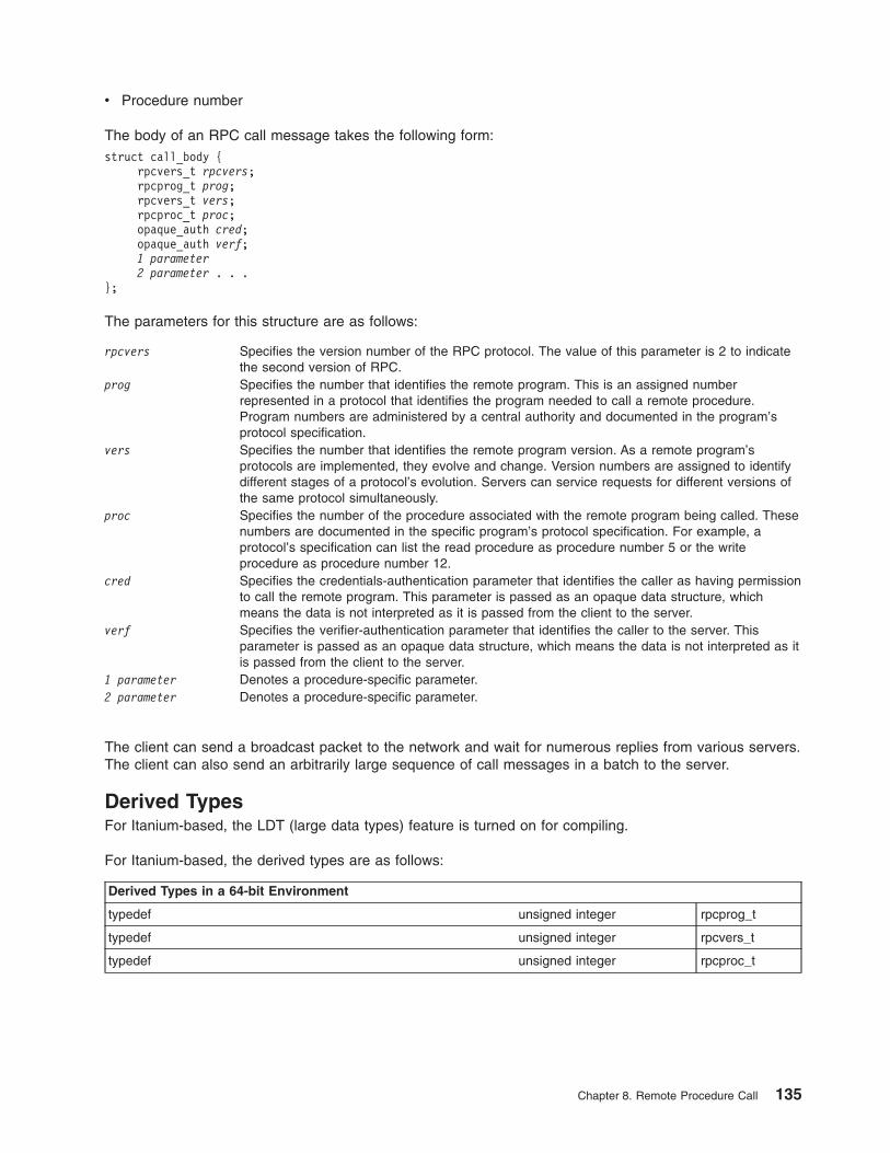
v Procedure number
The body of an RPC call message takes the following form:
struct call_body {
rpcvers_t rpcvers;
rpcprog_t prog;
rpcvers_t vers;
rpcproc_t proc;
opaque_auth cred;
opaque_auth verf;
1 parameter
2 parameter . . .
};
The parameters for this structure are as follows:
rpcvers Specifies the version number of the RPC protocol. The value of this parameter is 2 to indicate
the second version of RPC.
prog Specifies the number that identifies the remote program. This is an assigned number
represented in a protocol that identifies the program needed to call a remote procedure.
Program numbers are administered by a central authority and documented in the program’s
protocol specification.
vers Specifies the number that identifies the remote program version. As a remote program’s
protocols are implemented, they evolve and change. Version numbers are assigned to identify
different stages of a protocol’s evolution. Servers can service requests for different versions of
the same protocol simultaneously.
proc Specifies the number of the procedure associated with the remote program being called. These
numbers are documented in the specific program’s protocol specification. For example, a
protocol’s specification can list the read procedure as procedure number 5 or the write
procedure as procedure number 12.
cred Specifies the credentials-authentication parameter that identifies the caller as having permission
to call the remote program. This parameter is passed as an opaque data structure, which
means the data is not interpreted as it is passed from the client to the server.
verf Specifies the verifier-authentication parameter that identifies the caller to the server. This
parameter is passed as an opaque data structure, which means the data is not interpreted as it
is passed from the client to the server.
1 parameter Denotes a procedure-specific parameter.
2 parameter Denotes a procedure-specific parameter.
The client can send a broadcast packet to the network and wait for numerous replies from various servers.
The client can also send an arbitrarily large sequence of call messages in a batch to the server.
Derived Types
For Itanium-based, the LDT (large data types) feature is turned on for compiling.
For Itanium-based, the derived types are as follows:
Derived Types in a 64-bit Environment
typedef unsigned integer rpcprog_t
typedef unsigned integer rpcvers_t
typedef unsigned integer rpcproc_t
Chapter 8. Remote Procedure Call 135
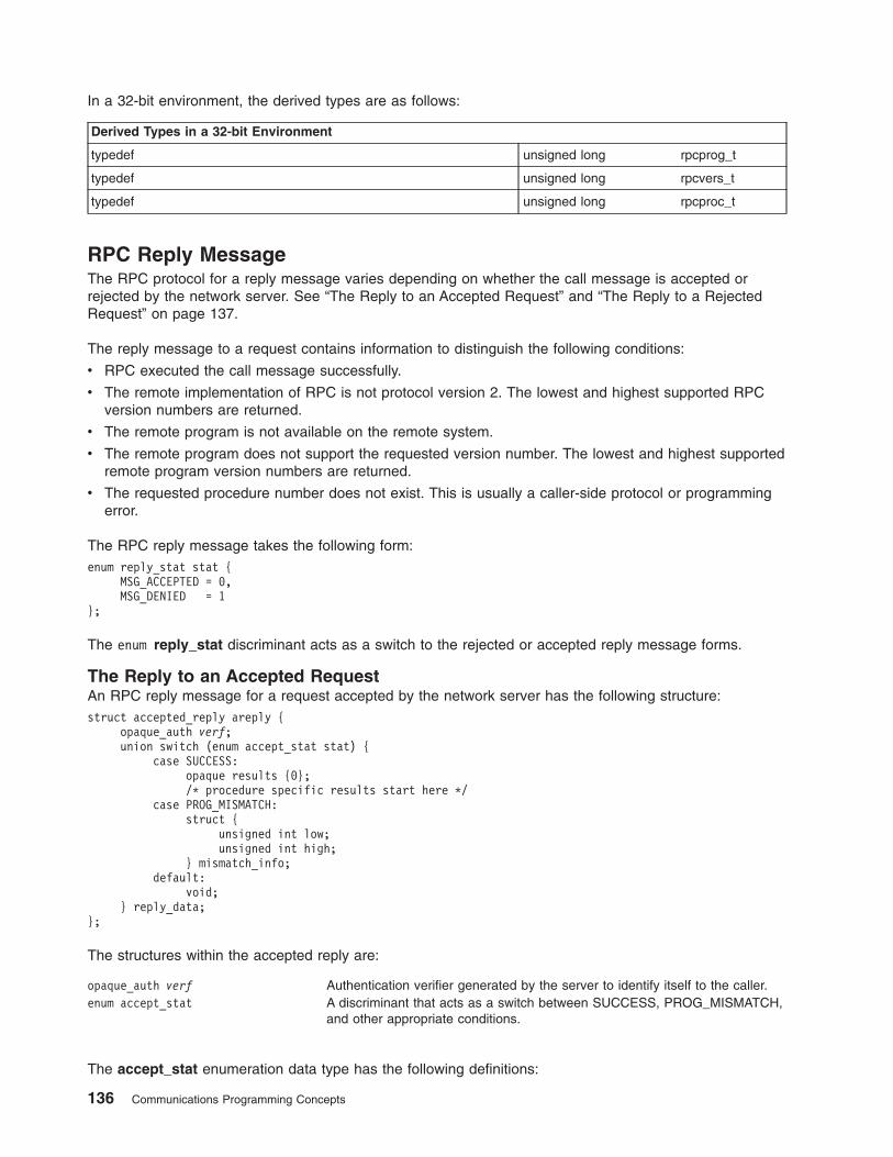
In a 32-bit environment, the derived types are as follows:
Derived Types in a 32-bit Environment
typedef unsigned long rpcprog_t
typedef unsigned long rpcvers_t
typedef unsigned long rpcproc_t
RPC Reply Message
The RPC protocol for a reply message varies depending on whether the call message is accepted or
rejected by the network server. See “The Reply to an Accepted Request” and “The Reply to a Rejected
Request” on page 137.
The reply message to a request contains information to distinguish the following conditions:
v RPC executed the call message successfully.
v The remote implementation of RPC is not protocol version 2. The lowest and highest supported RPC
version numbers are returned.
v The remote program is not available on the remote system.
v The remote program does not support the requested version number. The lowest and highest supported
remote program version numbers are returned.
v The requested procedure number does not exist. This is usually a caller-side protocol or programming
error.
The RPC reply message takes the following form:
enum reply_stat stat {
MSG_ACCEPTED = 0,
MSG_DENIED = 1
};
The enum reply_stat discriminant acts as a switch to the rejected or accepted reply message forms.
The Reply to an Accepted Request
An RPC reply message for a request accepted by the network server has the following structure:
struct accepted_reply areply {
opaque_auth verf;
union switch (enum accept_stat stat) {
case SUCCESS:
opaque results {0};
/* procedure specific results start here */
case PROG_MISMATCH:
struct {
unsigned int low;
unsigned int high;
} mismatch_info;
default:
void;
} reply_data;
};
The structures within the accepted reply are:
opaque_auth verf Authentication verifier generated by the server to identify itself to the caller.
enum accept_stat A discriminant that acts as a switch between SUCCESS, PROG_MISMATCH,
and other appropriate conditions.
The accept_stat enumeration data type has the following definitions:
136 Communications Programming Concepts
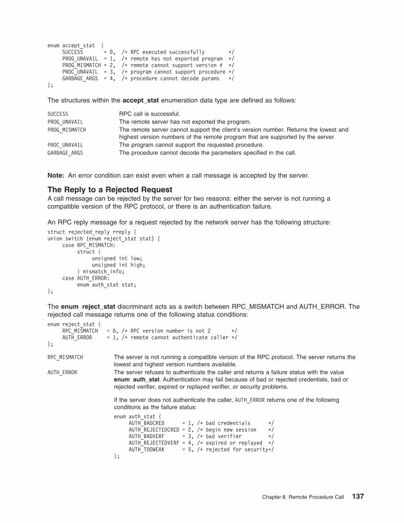
enum accept_stat {
SUCCESS = 0, /* RPC executed successfully */
PROG_UNAVAIL = 1, /* remote has not exported program */
PROG_MISMATCH = 2, /* remote cannot support version # */
PROC_UNAVAIL = 3, /* program cannot support procedure */
GARBAGE_ARGS = 4, /* procedure cannot decode params */
};
The structures within the accept_stat enumeration data type are defined as follows:
SUCCESS RPC call is successful.
PROG_UNAVAIL The remote server has not exported the program.
PROG_MISMATCH The remote server cannot support the client’s version number. Returns the lowest and
highest version numbers of the remote program that are supported by the server.
PROC_UNAVAIL The program cannot support the requested procedure.
GARBAGE_ARGS The procedure cannot decode the parameters specified in the call.
Note: An error condition can exist even when a call message is accepted by the server.
The Reply to a Rejected Request
A call message can be rejected by the server for two reasons: either the server is not running a
compatible version of the RPC protocol, or there is an authentication failure.
An RPC reply message for a request rejected by the network server has the following structure:
struct rejected_reply rreply {
union switch (enum reject_stat stat) {
case RPC_MISMATCH:
struct {
unsigned int low;
unsigned int high;
} mismatch_info;
case AUTH_ERROR:
enum auth_stat stat;
};
The enum reject_stat discriminant acts as a switch between RPC_MISMATCH and AUTH_ERROR. The
rejected call message returns one of the following status conditions:
enum reject_stat {
RPC_MISMATCH = 0, /* RPC version number is not 2 */
AUTH_ERROR = 1, /* remote cannot authenticate caller */
};
RPC_MISMATCH The server is not running a compatible version of the RPC protocol. The server returns the
lowest and highest version numbers available.
AUTH_ERROR The server refuses to authenticate the caller and returns a failure status with the value
enum auth_stat. Authentication may fail because of bad or rejected credentials, bad or
rejected verifier, expired or replayed verifier, or security problems.
If the server does not authenticate the caller, AUTH_ERROR returns one of the following
conditions as the failure status:
enum auth_stat {
AUTH_BADCRED = 1, /* bad credentials */
AUTH_REJECTEDCRED = 2, /* begin new session */
AUTH_BADVERF = 3, /* bad verifier */
AUTH_REJECTEDVERF = 4, /* expired or replayed */
AUTH_TOOWEAK = 5, /* rejected for security*/
};
Chapter 8. Remote Procedure Call 137
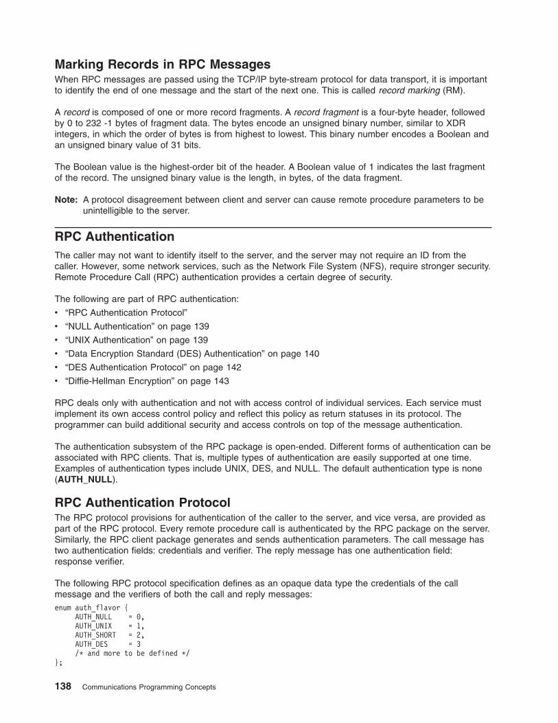
Marking Records in RPC Messages
When RPC messages are passed using the TCP/IP byte-stream protocol for data transport, it is important
to identify the end of one message and the start of the next one. This is called record marking (RM).
A record is composed of one or more record fragments. A record fragment is a four-byte header, followed
by 0 to 232 -1 bytes of fragment data. The bytes encode an unsigned binary number, similar to XDR
integers, in which the order of bytes is from highest to lowest. This binary number encodes a Boolean and
an unsigned binary value of 31 bits.
The Boolean value is the highest-order bit of the header. A Boolean value of 1 indicates the last fragment
of the record. The unsigned binary value is the length, in bytes, of the data fragment.
Note: A protocol disagreement between client and server can cause remote procedure parameters to be
unintelligible to the server.
RPC Authentication
The caller may not want to identify itself to the server, and the server may not require an ID from the
caller. However, some network services, such as the Network File System (NFS), require stronger security.
Remote Procedure Call (RPC) authentication provides a certain degree of security.
The following are part of RPC authentication:
v “RPC Authentication Protocol”
v “NULL Authentication” on page 139
v “UNIX Authentication” on page 139
v “Data Encryption Standard (DES) Authentication” on page 140
v “DES Authentication Protocol” on page 142
v “Diffie-Hellman Encryption” on page 143
RPC deals only with authentication and not with access control of individual services. Each service must
implement its own access control policy and reflect this policy as return statuses in its protocol. The
programmer can build additional security and access controls on top of the message authentication.
The authentication subsystem of the RPC package is open-ended. Different forms of authentication can be
associated with RPC clients. That is, multiple types of authentication are easily supported at one time.
Examples of authentication types include UNIX, DES, and NULL. The default authentication type is none
(AUTH_NULL).
RPC Authentication Protocol
The RPC protocol provisions for authentication of the caller to the server, and vice versa, are provided as
part of the RPC protocol. Every remote procedure call is authenticated by the RPC package on the server.
Similarly, the RPC client package generates and sends authentication parameters. The call message has
two authentication fields: credentials and verifier. The reply message has one authentication field:
response verifier.
The following RPC protocol specification defines as an opaque data type the credentials of the call
message and the verifiers of both the call and reply messages:
enum auth_flavor {
AUTH_NULL = 0,
AUTH_UNIX = 1,
AUTH_SHORT = 2,
AUTH_DES = 3
/* and more to be defined */
};
138 Communications Programming Concepts
struct opaque_auth {
auth_flavor flavor;
opaque body<400>;
};
Any opaque_auth structure is an auth_flavor enumeration followed by bytes that are opaque to the RPC
protocol implementation. The interpretation and semantics of the data contained within the authentication
fields are specified by individual, independent authentication protocol specifications.
If authentication parameters are rejected, response messages state the reasons. A server can support
multiple types of authentication at one time.
NULL Authentication
Sometimes, the RPC caller does not know its own identity or the server does not need to know the caller’s
identity. In these cases, the AUTH_NULL authentication type can be used in both the call message and
response messages. The bytes of the opaque_auth body are undefined. The opaque length should be 0.
UNIX Authentication
A process calling a remote procedure might need to identify itself as it is identified on the UNIX system.
The value of the credential’s discriminant of an RPC call message is AUTH_UNIX. The bytes of the
credential’s opaque body encode the following structure:
struct auth_unix {
unsigned stamp;
string machinename;
unsigned uid;
unsigned gid;
unsigned gids;
};
The parameters in the structure are defined as follows:
stamp Specifies the arbitrary ID generated by the caller’s workstation.
machinename Specifies the name of the caller’s workstation. The name must not exceed 255 bytes in length.
uid Specifies the caller’s effective user ID.
gid Specifies the caller’s effective group ID.
gids Specifies the counted array of group IDs that contain the caller as a member. A maximum of 10
groups is allowed.
The verifier accompanying the credentials should be AUTH_NULL.
The value of the discriminant in the response verifier of the reply message from the server is either
AUTH_NULL or AUTH_SHORT. If the value is AUTH_SHORT, the bytes of the response verifier’s string
encode an opaque structure. The new opaque structure can then be passed to the server in place of the
original AUTH_UNIX credentials. The server maintains a cache that maps shorthand opaque structures
(passed back by way of an AUTH_SHORT-style response verifier) to the original credentials of the caller.
The caller saves network bandwidth and server CPU time when the shorthand credentials are used.
Note: The server can eliminate, or flush, the shorthand opaque structures at any time. If this happens, the
RPC message will be rejected due to an AUTH_REJECTEDCRED authentication error. The original
AUTH_UNIX credentials can be used when this happens.
UNIX Authentication on the Client Side
When a caller creates a new RPC client handle, the authentication handle of the appropriate transport is
set to the default by the authnone_create subroutine. The default for an RPC authentication handle is
NULL. After creating the client handle, the client can select UNIX authentication with the authunix_create
Chapter 8. Remote Procedure Call 139
routine. This routine creates an authentication handle with operating system permissions and causes each
remote procedure call associated with the handle to carry UNIX credentials.
Note: Authentication information can be destroyed with the auth_destroy subroutine. Authentication
information should be destroyed if one is attempting to conserve memory.
For more information, see the “Using UNIX Authentication Example” on page 166.
UNIX Authentication on the Server Side
Dealing with authentication issues on the server side is more difficult than dealing with them on the client
side. The caller’s RPC package passes the service dispatch routine a request that has an arbitrary
authentication style associated with it. The server must then determine which style of authentication the
caller used and whether the style is supported by the RPC package.
If the authentication parameter type is not suitable for the calling service, the service dispatch routine calls
the svcerr_weakauth routine to refuse the remote procedure call. It is not customary for the server to
check the authentication parameters associated with procedure 0 (NULLPROC).
If the service does not have the requested protocol, the service dispatch returns a status for access
denied. The svcerr_systemerr primitive is called to detect a system error that is not covered by a service
protocol.
Data Encryption Standard (DES) Authentication
DES authentication offers more security features than UNIX authentication. For DES authentication to
work, the keyserv daemon must be running on both the server and client machines. The users at these
workstations need public keys assigned in the public key database by the person administering the
network. Additionally, each user’s secret key must be decrypted using their keylogin command password.
DES authentication can handle the following UNIX problems:
v The naming scheme within UNIX authentication is UNIX-system oriented.
v UNIX authentication lacks a verifier, thereby allowing falsification of credentials.
For more information, see the “DES Authentication Example” on page 168.
DES Authentication Naming Scheme
DES addresses the caller with a simple string of characters instead of an integer specific to a particular
operating system. This string of characters is known as the caller’s network name, or net name. The
server is allowed to interpret the contents of the net name only to identify the caller. Therefore, net names
should be unique for each caller in the network.
Each operating system is responsible for implementing DES authentication to generate unique net names
for calling on remote servers. Because operating systems can already distinguish local users to their
systems, extending this mechanism to the network is simple.
For example, a UNIX user at company xyz with a user ID of 515 might be assigned the following net
name: [email protected]. This net name contains three items that ensure uniqueness. First, only one
naming domain in the Internet is called xyz.com. In this domain, there is only one UNIX user with user ID
515. Another user on another operating system, such as VMS, in the same naming domain can have the
same user ID. However, two users are distinguished by the operating system name. In this example, one
user is [email protected] and the other is [email protected].
The first field is actually a naming method rather than an operating system name. Currently, a one-to-one
correspondence between naming methods and operating systems exists. If a universal naming standard is
agreed upon, the first field will become the name of that standard instead of an operating system name.
140 Communications Programming Concepts
DES Authentication Verifiers
Unlike UNIX authentication, DES authentication has a verifier that permits the server to validate the client’s
credential and the client to validate the server’s credential. The content of this verifier is primarily an
encrypted time stamp. The time stamp is encrypted by the client and decrypted by the server. If the time
stamp is close to real time, then the client encrypted it correctly. To encrypt the time stamp correctly, the
client must have the conversation key of the RPC session. The client with the conversation key is the
authentic client.
The conversation key is a DES key that the client generates and includes in its first remote procedure call
to the server. The conversation key is encrypted using a public key scheme in the first transaction. The
particular public key scheme used in DES authentication is the Diffie-Hellman system with 192-bit keys.
For more information, see “Diffie-Hellman Encryption” on page 143.
For successful validation, both the client and the server need the same notion of current time. If network
time synchronization cannot be guaranteed, the client can synchronize with the server before beginning
the conversation, perhaps by consulting the Internet Time Server (TIME).
DES Authentication on the Server Side
The method for determining the validity of a client’s time stamp depends on which transaction is under
consideration. For the first transaction, the server checks only that the time stamp has not expired. For
subsequent transactions, the server verifies that the time stamp is greater than the previous time stamp
from the same client, and that the time stamp has not expired. A time stamp has expired if the server’s
time is later than the sum of the client’s time stamp plus the client’s window. The sum of the time stamp
plus the client’s window can be thought of as the lifetime of the credential.
DES Authentication on the Client Side
In the first transaction to the server, the client sends an encrypted item, the window verifier, that must
equal the client’s window minus one, as an added check. Otherwise, the client could successfully send
random data instead of the time stamp. Other values for the credential are rejected by the server. If the
window verifier is accepted by the server, the server returns to the client a verifier equal to the encrypted
time stamp, minus one second. If the client receives a different time stamp from the server, the client
rejects it.
For subsequent transactions, the client’s time stamp is valid if it is greater than the previous time stamp,
and has not expired. A time stamp has expired if the server’s time is later than the sum of the client’s time
stamp plus the client’s window. The sum of the time stamp plus the client window can be thought of as the
lifetime of the credential.
To use DES authentication, the programmer must set the client authentication handle using the
authdes_create subroutine. This subroutine requires the network name of the owner of the server
process, a lifetime for the credential, the address of the host with which to synchronize, and the address of
a DES encryption key to use for encrypting time stamps and data.
Nicknames
The server’s DES authentication subsystem returns a nickname to the client in the verifier response to the
first transaction. The nickname is an unsigned integer. The nickname is likely to be an index into a table
on the server that stores each client’s net name, decrypted DES key, and window. The client can use the
nickname in all subsequent transactions instead of passing its net name, encrypted DES key, and window
each time. The nickname is not required, but it saves time.
Clock Synchronization
Although the client and server clocks are originally synchronized, they can lose this synchronization. When
this happens, the client RPC subsystem normally receives the RPC_AUTHERROR error message and
should resynchronize.
Chapter 8. Remote Procedure Call 141
A client can receive the RPC_AUTHERROR message even when the clocks are synchronized. The
message indicates that the server’s nickname table has been flushed either because of the table’s size
limitations or a server crash. To receive new nicknames, all clients must resend their original credentials to
the server.
DES Authentication Protocol
DES authentication has the following form of eXternal Data Representation (XDR) enumeration:
enum authdes_namekind {
ADN_FULLNAME = 0,
ADN_NICKNAME = 1
};
typedef opaque des_block[8];
const MAXNETNAMELEN = 255;
A credential is either a client’s full network name or its nickname. For the first transaction with the server,
the client must use its full name. For subsequent transactions, the client can use its nickname. DES
authentication protocol includes a 64-bit block of encrypted DES data and specifies the maximum length of
a network user’s name.
The authdes_cred union provides a switch between the full-name and nickname forms, as follows:
union authdes_cred switch (authdes_namekind adc_namekind) {
case ADN_FULLNAME:
authdes_fullname adc_fullname;
case ADN_NICKNAME:
unsigned int adc_nickname;
};
The full name contains the network name of the client, an encrypted conversation key, and the window.
The window is actually a lifetime for the credential. The server can terminate a client’s time stamp and not
grant the request if the time indicated by the verifier time stamp plus the window has expired. In the first
transaction, the server confirms that the window verifier is one second less than the window. To ensure
that requests are granted only once, the server can require time stamps in subsequent requests to be
greater than the client’s previous time stamps.
The structure for a credential using the client’s full network name follows:
struct authdes_fullname {
string name<MAXNETNAMELEN>; /* name of client */
des_block key; /*PK encrypted conversation key*/
unsigned int window; /* encrypted window */
};
A time stamp encodes the time since midnight, January 1, 1970. The structure for the time stamp follows:
struct timestamp {
unsigned int seconds; /* seconds */
unsigned int useconds; /* and microseconds */
The client verifier has the following structure:
struct {
adv_timestamp; /* one DES block */
adc_fullname.window; /* one half DES block */
adv_winverf; /* one half DES block */
}
The window verifier is only used in the first transaction. In conjunction with the fullname credential, these
items are packed into the structure shown previously before being encrypted.
This structure is encrypted using CBC mode encryption with an input vector of 0. All other time stamp
encryptions use ECB mode encryption. The client’s verifier has the following structure:
142 Communications Programming Concepts
struct authdes_verf_clnt {
timestamp adv_timestamp; /* encrypted timestamp */
unsigned int adv_winverf; /* encrypted window verifier */
};
The server returns the client’s time stamp, minus one second, in an encrypted response verifier. This
verifier also sends the client an unencrypted nickname to be used in future transactions. The verifier from
the server has the following structure:
struct authdes_verf_svr {
timestamp adv_timeverf; /* encrypted verifier */
unsigned int adv_nickname; /* new nickname for client */
};
Diffie-Hellman Encryption
The public key scheme used in DES authentication is Diffie-Hellman with 192-bit keys. The Diffie-Hellman
encryption scheme includes two constants: BASE and MODULUS. Their values for these for the DES
authentication protocol are:
const BASE = 3;
const MODULUS = "d4a0ba0250b6fd2ec626e7efd637df76c716e22d0944b88b"; /* hex */
Two programmers, A and B, can send encrypted messages to each other in the following manner. First,
programmers A and B independently generate secret keys at random, which can be represented as SK(A)
and SK(B). Both programmers then publish their public keys PK(A) and PK(B) in a public directory. These
public keys are computed from the secret keys as follows:
PK(A) = ( BASE ** SK(A) ) mod MODULUS
PK(B) = ( BASE ** SK(B) ) mod MODULUS
The ** (double asterisk) notation represents exponentiation. Programmers A and B can both arrive at the
common key, represented here as CK(A, B), without revealing their secret keys.
Programmer A computes:
CK(A, B) = ( PK(B) ** SK(A)) mod MODULUS
while programmer B computes:
CK(A, B) = ( PK(A) ** SK(B)) mod MODULUS
These two can be shown to be equivalent:
(PK(B) ** SK(A)) mod MODULUS = (PK(A) ** SK(B)) mod MODULUS
If the mod MODULUS parameter is omitted, modulo arithmetic can simplify things as follows:
PK(B) ** SK(A) = PK(A) ** SK(B)
Then, if the result of the previous computation on B replaces PK(B) and the previous computation of A
replaces PK(A), the equation is:
((BASE ** SK(B)) ** SK(A) = (BASE ** SK(A)) ** SK(B)
This equation can be simplified as follows:
BASE ** (SK(A) * SK(B)) = BASE ** (SK(A) * SK(B))
This produces a common key CK(A, B). This common key is not used directly to encrypt the time stamps
used in the protocol. Instead, it is used to encrypt a conversation key that is then used to encrypt the time
stamps. In this way, the common key is used as little as possible to prevent it from being broken. Breaking
the conversation key usually has less serious consequences because conversations are relatively
shortlived.
Chapter 8. Remote Procedure Call 143
The conversation key is encrypted using 56-bit DES keys, while the common key is 192 bits. To reduce
the number of bits, 56 bits are selected from the common key as follows. The middle eight bytes are
selected from the common key and parity is added to the lower order bit of each byte, producing a 56-bit
key with eight bits of parity.
RPC Port Mapper Program
Client programs must find the port numbers of the server programs that they intend to use. Network
transports do not provide such a service; they merely provide process-to-process message transfer across
a network. A message typically contains a transport address consisting of a network number, a host
number, and a port number.
A port is a logical communications channel in a host. A server process receives messages from the
network by waiting on a port. How a process waits on a port varies from one operating system to another,
but all systems provide mechanisms that suspend processes until a message arrives at a port. Therefore,
messages are sent to the ports at which receiving processes wait for messages.
Ports allow message receivers to be specified in a way that is independent of the conventions of the
receiving operating system. The port mapper protocol defines a network service that permits clients to look
up the port number of any remote program supported by the server. Because the port mapper program
can be implemented on any transport that provides the equivalent of ports, it works for all clients, all
servers, and all networks.
The port mapper program maps Remote Procedure Call (RPC) program and version numbers to
transport-specific port numbers. The port mapper program makes dynamic binding of remote programs
possible. This is desirable because the range of reserved port numbers is small and the number of
potential remote programs large. When running only the port mapper on a reserved port, the port numbers
of other remote programs can be determined by querying the port mapper.
The port mapper also aids in broadcast RPC. A given RPC program usually has different port number
bindings on different machines, so there is no way to directly broadcast to all of these programs. The port
mapper, however, has a fixed port number. To broadcast to a given program, the client sends its message
to the port mapper located at the broadcast address. Each port mapper that picks up the broadcast then
calls the local service specified by the client. When the port mapper receives a reply from the local
service, it sends the reply back to the client.
Registering Ports
Every port mapper on every host is associated with port number 111. The port mapper is the only network
service that must have a dedicated port. Other network services can be assigned port numbers either
statically or dynamically, as long as the services register their ports with their host’s port mapper. Typically,
a server program based on an RPC library gets a port number at run time by calling an RPC library
procedure.
Note: A service on a host can be associated with a different port every time its server program is started.
For example, a given network service can be associated with port number 256 on one server and
port number 885 on another.
The delegation of port-to-remote program mapping to a port mapper also automates port number
administration. Statically mapping ports and remote programs in a file duplicated on each client requires
updating all mapping files whenever a new remote program is introduced to a network. The alternative
solution, placing the port-to-program mappings in a shared Network File System (NFS) file, would be too
centralized. If the file server were to go down in this case, the entire network would also.
The port-to-program mappings, which are maintained by the port mapper server, are called a portmap. The
port mapper is started automatically whenever a machine is booted. Both the server programs and the
144 Communications Programming Concepts
client programs call port mapper procedures. As part of its initialization, a server program calls its host’s
port mapper to create a portmap entry. Whereas server programs call port mapper programs to update
portmap entries, clients call port mapper programs to query portmap entries. To find a remote program’s
port, a client sends an RPC call message to a server’s port mapper. If the remote program is supported on
the server, the port mapper returns the relevant port number in an RPC reply message. The client program
can then send RPC call messages to the remote program’s port. A client program can minimize port
mapper calls by caching the port numbers of recently called remote programs.
Note: The port mapper provides an inherently useful service because a portmap is a set of associations
between registrants and ports.
Port Mapper Protocol
The following is the port mapper protocol specification in RPC language:
const PMAP_PORT = 111; /* port mapper port number */
The mapping of program (prog), version (vers), and protocol (prot) to the port number (port) is shown by
the following structure:
struct mapping {
unsigned int prog;
unsigned int vers;
unsigned int prot;
unsigned int port;
};
The values supported for the prot parameter are:
const IPPROTO_TCP = 6; /* protocol number for TCP/IP */
const IPPROTO_UDP = 17; /* protocol number for UDP */
The list of mappings takes the following structure:
struct *pmaplist {
mapping map;
pmaplist next;
};
The structure for arguments to the callit parameter follows:
struct call_args {
unsigned int prog;
unsigned int vers;
unsigned int proc;
opaque args<>;
};
The results of the callit parameter have the following structure:
struct call_result {
unsigned int port;
opaque res<>;
};
The structure for port mapper procedures follows:
program PMAP_PROG {
version PMAP_VERS {
void
PMAPPROC_NULL(void) = 0;
bool
PMAPPROC_SET(mapping) = 1;
bool
PMAPPROC_UNSET(mapping) = 2;
Chapter 8. Remote Procedure Call 145
unsigned int
PMAPPROC_GETPORT(mapping) = 3;
pmaplist
PMAPPROC_DUMP(void) = 4;
call_result
PMAPPROC_CALLIT(call_args) = 5;
} = 2;
} = 100000;
Port Mapper Procedures
The port mapper program currently supports two protocols: User Datagram Protocol (UDP) and
Transmission Control Protocol/Internet Protocol (TCP/IP). The port mapper is contacted by port number
111 on both protocols.
A description of the port mapper procedures follows.
PMAPPROC_NULL This procedure does no work. By convention, procedure 0 of any protocol takes no
parameters and returns no results.
PMAPPROC_SET When a program first becomes available on a machine, it registers itself with the port
mapper program on that machine. The program passes its program number (prog),
version number (vers), transport protocol number (prot), and the port (port) on which
it awaits service request. The procedure returns a Boolean response whose value is
either True if the procedure successfully established the mapping, or False if
otherwise. The procedure does not establish a mapping if the values for the prog,
vers, and prot parameters indicate a mapping already exists.
PMAPPROC_UNSET When a program becomes unavailable, it should unregister itself with the port mapper
program on the same machine. The parameters and results have meanings identical
to those of the PMAPPROC_SET procedure. The protocol and port number fields of
the argument are ignored.
PMAPPROC_GETPORT Given a program number (prog), version number (vers), and transport protocol
number (prot), this procedure returns the port number on which the program is
awaiting call requests. A port value of zero means the program has not been
registered. The port parameter of the argument is then ignored.
PMAPPROC_DUMP This procedure enumerates all entries in the port mapper database. The procedure
takes no parameters and returns a list of prog, vers, prot, and port values.
PMAPPROC_CALLIT This procedure allows a caller to call another remote procedure on the same machine
without knowing the remote procedure’s port number. It supports broadcasts to
arbitrary remote programs through the well-known port mapper port. The prog, vers,
and proc parameters, and the bytes of the args parameter of an RPC call represent
the program number, version number, procedure number, and arguments,
respectively. The PMAPPROC_CALLIT procedure sends a response only if the
procedure is successfully run. The port mapper communicates with the remote
program using UDP only. The procedure returns the remote program’s port number,
and the bytes of results are the results of the remote procedure.
Programming in RPC
Remote procedure calls can be made from any language. Remote Procedure Call (RPC) protocol is
generally used to communicate between processes on different workstations. However, RPC works just as
well for communication between different processes on the same workstation.
The RPC interface can be seen as being divided into three layers: highest, intermediate, and lowest. See
the following:
v “Using the Highest Layer of RPC” on page 149
v “Using the Intermediate Layer of RPC” on page 149
v “Using the Lowest Layer of RPC” on page 151
146 Communications Programming Concepts

The highest layer of RPC is totally transparent to the operating system, workstation, and network on which
it runs. This level is actually a method for using RPC routines, rather than a part of RPC proper.
The intermediate layer is RPC proper. At the intermediate layer, the programmer need not consider details
about sockets or other low-level implementation mechanisms. The programmer makes remote procedure
calls to routines on other workstations.
The lowest layer of RPC allows the programmer greatest control. Programs written at this level can be
more efficient.
Both intermediate and lower-level RPC programming entail assigning program numbers (“Assigning
Program Numbers”), version numbers (“Assigning Version Numbers”), and procedure numbers (“Assigning
Procedure Numbers” on page 148). An RPC server can be started from the inetd daemon (“Starting RPC
from the inetd Daemon” on page 153).
Assigning Program Numbers
A central system authority administers the program number (prog parameter). A program number permits
the implementation of a remote program. The first implementation of a program is usually version number
1.
A program number is assigned by groups of 0x20000000 (decimal 536870912), according to the following
list:
0-1xxxxxxx This group of numbers is predefined and administered by the operating system.
The numbers should be identical for all system customers.
20000000-3xxxxxxx The user defines this group of numbers. The numbers are used for new
applications and for debugging new programs.
40000000-5xxxxxxx This group of numbers is transient and is used for applications that generate
program numbers dynamically.
60000000-7xxxxxxx Reserved.
80000000-9xxxxxxx Reserved.
a0000000-bxxxxxxx Reserved.
c0000000-dxxxxxxx Reserved.
e0000000-fxxxxxxxx Reserved.
The first group of numbers is predefined, and should be identical for all customers. If a customer develops
an application that might be of general interest, that application can be registered by assigning a number
in the first range. The second group of numbers is reserved for specific customer applications. This range
is intended primarily for debugging new programs. The third group is reserved for applications that
generate program numbers dynamically. The final groups are reserved for future use and should not be
used.
Assigning Version Numbers
Most new protocols evolve into more efficient, stable, and mature protocols. As a program evolves, a new
version number (vers parameter) is assigned. The version number identifies which version of the protocol
the caller is using. The first implementation of a remote program is usually designated as version number
1 (or a similar form). Version numbers make it possible to use old and new protocols through the same
server. See “Using Multiple Program Versions Example” on page 176.
Just as remote program protocols may change over several versions, the actual RPC message protocol
can also change. Therefore, the call message also contains the RPC version number. In the second
version of the RPC protocol specification, the version number is always 2.
Chapter 8. Remote Procedure Call 147
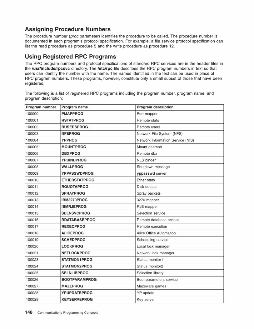
Assigning Procedure Numbers
The procedure number (proc parameter) identifies the procedure to be called. The procedure number is
documented in each program’s protocol specification. For example, a file service protocol specification can
list the read procedure as procedure 5 and the write procedure as procedure 12.
Using Registered RPC Programs
The RPC program numbers and protocol specifications of standard RPC services are in the header files in
the /usr/include/rpcsvc directory. The /etc/rpc file describes the RPC program numbers in text so that
users can identify the number with the name. The names identified in the text can be used in place of
RPC program numbers. These programs, however, constitute only a small subset of those that have been
registered.
The following is a list of registered RPC programs including the program number, program name, and
program description:
Program number Program name Program description
100000 PMAPPROG Port mapper
100001 RSTATPROG Remote stats
100002 RUSERSPROG Remote users
100003 NFSPROG Network File System (NFS)
100004 YPPROG Network Information Service (NIS)
100005 MOUNTPROG Mount daemon
100006 DBXPROG Remote dbx
100007 YPBINDPROG NLS binder
100008 WALLPROG Shutdown message
100009 YPPASSWDPROG yppasswd server
100010 ETHERSTATPROG Ether stats
100011 RQUOTAPROG Disk quotas
100012 SPRAYPROG Spray packets
100013 IBM3270PROG 3270 mapper
100014 IBMRJEPROG RJE mapper
100015 SELNSVCPROG Selection service
100016 RDATABASEPROG Remote database access
100017 REXECPROG Remote execution
100018 ALICEPROG Alice Office Automation
100019 SCHEDPROG Scheduling service
100020 LOCKPROG Local lock manager
100021 NETLOCKPROG Network lock manager
100023 STATMON1PROG Status monitor1
100024 STATMON2PROG Status monitor2
100025 SELNLIBPROG Selection library
100026 BOOTPARAMPROG Boot parameters service
100027 MAZEPROG Mazewars games
100028 YPUPDATEPROG YP update
100029 KEYSERVEPROG Key server
148 Communications Programming Concepts

Program number Program name Program description
100030 SECURECMDPROG Secure login
100031 NETFWDIPROG NFS net forwarder init
100032 NETFWDTPROG NFS net forwarder trans
100033 SUNLINKMAP_PROG Sunlink MAP
100034 NETMONPROG Network monitor
100035 DBASEPROG Lightweight database
100036 PWDAUTHPROG Password authorization
100037 TFSPROG Translucent file service
100038 NSEPROG NSE server
100039 NSE_ACTIVATE_PROG NSE activate daemon
150001 PCNFSDPROGx PC password authorization
200000 PYRAMIDLOCKINGPROG Pyramid-locking
200001 PYRAMIDSYS5 Pyramid-sys5
200002 CADDS_IMAGE CV cadds_image
300001 ADT_RFLOCKPROG ADT file locking
Using the Highest Layer of RPC
Programmers who write remote procedure calls can make the highest layer of RPC available to other
users through a simple C language front-end routine that entirely hides the networking. To illustrate a call
at the highest level, a program can call the rnusers routine, a C routine that returns the number of users
on a remote workstation. The user need not be explicitly aware of using RPC.
Other RPC service library routines available to the C programmer are as follows:
rusers Returns information about users on a remote workstation.
havedisk Determines whether the remote workstation has a disk.
rstat Gets performance data from a remote kernel.
rwall Writes to a specified remote workstation.
yppasswd Updates a user password in the Network Information Service (NIS).
RPC services, such as the mount and spray commands, are not available to the C programmer as
service library routines. Though unavailable, these services have RPC program numbers and can be
invoked with the callrpc subroutine. Most of these services have compilable rpcgen protocol description
files that simplify the process of developing network applications.
For more information, see “Using the Highest Layer of RPC Example” on page 170.
Using the Intermediate Layer of RPC
The intermediate layer RPC routines are used for most applications. The intermediate layer is sometimes
overlooked in programming due to its simplicity and lack of flexibility. At this level, RPC does not allow
time-out specifications, choice of transport, or process control in case of errors. Nor does the intermediate
layer of RPC support multiple types of call authentication. The programmer often needs these kinds of
control.
Chapter 8. Remote Procedure Call 149
Remote procedure calls are made with the registerrpc, callrpc, and svc_run system routines, which
belong to the intermediate layer of RPC. The registerrpc and callrpc routines are the most fundamental.
The registerrpc routine obtains a unique system-wide procedure identification number. The callrpc routine
executes the remote procedure call.
Each RPC procedure is uniquely defined by a program number, version number, and procedure number.
The program number specifies a group of related remote procedures, each of which has a different
procedure number. Each program also has a version number. Therefore, when a minor change, such as
adding a new procedure, is made to a remote service, a new program number need not be assigned.
The RPC interface also handles arbitrary data structures (“Passing Arbitrary Data Types” on page 151),
regardless of the different byte orders or structure layout conventions at various workstations. For more
information, see the “Using the Intermediate Layer of RPC Example” on page 170.
Using the registerrpc Routine
Only the User Datagram Protocol (UDP) transport mechanism can use the registerrpc routine. This
routine is always safe in conjunction with calls generated by the callrpc routine. The UDP transport
mechanism can deal only with arguments and results that are less than 8KB in length.
The RPC registerrpc routine includes the following parameters:
v Program number
v Version number
v Procedure number to be called
v Procedure name
v XDR (eXternal Data Representation) subroutine that decodes the procedure parameters
v XDR subroutine that encodes the procedure calls
After registering the local procedure, the server program’s main procedure calls the svc_run routine,
which is the RPC library’s remote procedure dispatcher. The svc_run routine then calls the remote
procedure in response to RPC messages. The dispatcher uses the XDR data filters that are specified
when the remote procedure is registered to handle decoding procedure arguments and encoding results.
Using the callrpc Routine
The RPC callrpc routine executes remote procedure calls. See “Using the Intermediate Layer of RPC
Example” on page 170.
The callrpc routine includes the following parameters:
v Name of the remote server workstation
v Program number
v Version number of the program
v Procedure number
v Input XDR filter primitive
v Argument to be encoded and passed to the remote procedure
v Output XDR filter for decoding the results returned by the remote procedure
v Pointer to the location where the procedure’s results are to be stored
Multiple arguments and results can be embedded in structures. If the callrpc routine completes
successfully, it returns a value of zero. Otherwise, it returns a nonzero value. The return codes are cast in
integer data-type values in the rpc/clnt.h file.
If the callrpc routine gets no answer after several attempts to deliver a message, it returns with an error
code. The delivery mechanism is UDP. Adjusting the number of retries or using a different protocol
requires the use of the lower layer of the RPC library.
150 Communications Programming Concepts

Passing Arbitrary Data Types
The RPC interface can handle arbitrary data structures, regardless of the different byte orders or structure
layout conventions on different machines, by converting the structures to a network standard called XDR
before sending them over the wire. The process of converting from a particular machine representation to
XDR format is called serializing, and the reverse process is called deserializing.
The input and output parameters of the callrpc and registerrpc routines can be a built-in or user-supplied
procedure. For more information, see “Showing How RPC Passes Arbitrary Data Types Example” on page
175.
The XDR language has the following built-in subroutines:
v xdr_bool
v xdr_char
v xdr_u_char
v xdr_enum
v xdr_int
v xdr_u_int
v xdr_long
v xdr_u_long
v xdr_short
v xdr_u_short
v xdr_wrapstring
Although the xdr_string subroutine exists, it passes three parameters to its XDR routine. The xdr_string
subroutine cannot be used with the callrpc and registerrpc subroutines, which pass only two parameters.
However, the xdr_string routine can be called with the xdr_wrapstring routine, which also has only two
parameters.
If completion is successful, XDR subroutines return a nonzero value (that is, a True value in the C
language). Otherwise, they return a value of zero (False).
In addition to the built-in primitives are the following prefabricated building blocks:
v xdr_array
v xdr_bytes
v xdr_opaque
v xdr_pointer
v xdr_reference
v xdr_string
v xdr_union
v xdr_vector
Note: An RPC client and server system that uses the TCP protocol cannot get or put more than 64
megabytes (MB) in one RPC call. The constant TCP_MAX_REQUEST_SIZE limits this.
In addition to this constant, there is also a user limit on the size, which is 44 bytes less than the
limit. In addition, security protocols may take an additional 800 bytes off the limit.
Using the Lowest Layer of RPC
For the higher layers, RPC takes care of many details automatically. However, the lowest layer of the RPC
library allows the programmer to change the default values for these details. The lowest layer of RPC
Chapter 8. Remote Procedure Call 151
requires familiarity with sockets and their system calls. For more information, see “Using the Lowest Layer
of RPC Example” on page 171 and “Using Multiple Program Versions Example” on page 176.
The lowest layer of RPC may be necessary in the following situations:
v The programmer needs to use Transmission Control Protocol/Internet Protocol (TCP/IP). Higher layers
use UDP, which restricts RPC calls to 8KB of data. TCP/IP permits calls to send long streams of data.
v The programmer wants to allocate and free memory while serializing or deserializing messages with
XDR routines. No system call at the higher levels explicitly permits freeing memory. XDR routines are
used for memory allocation as well as for input and output.
v The programmer needs to perform authentication on the client or server side by supplying credentials or
verifying them, respectively.
Allocating Memory with XDR
XDR routines not only do input and output, they also do memory allocation. Consider the following XDR
routine, xdr_chararr1, which deals with a fixed array of bytes with length SIZE.
xdr_chararr1 (xdrsp, chararr)
XDR *xdrsp;
char chararr[];
{
char *p;
int len;
p = chararr;
len = SIZE;
return (xdr_bytes (xdrsp, &p, &len, SIZE));
}
If space has already been allocated in it, chararr can be called from a server. For example:
char chararr [SIZE];
svc_getargs (transp, xdr_chararr1, chararr);
If you want XDR to do the allocation, you need to rewrite this routine in the following way:
xdr_chararr2 (xdrsp, chararrp)
XDR *xdrsp;
char **chararrp;
{
int len;
len = SIZE;
return (xdr_bytes (xdrsp, charrarrp, &len, SIZE));
}
Then the RPC call might look like this:
char *arrptr;
arrptr = NULL;
svc_getargs (transp, xdr_chararr2, &arrptr);
/*
*Use the result here
*/
svc_freeargs (transp, xdr_chararr2, &arrptr);
The character array can be freed with the svc_freeargs macro. This operation does not attempt to free
any memory in the variable, indicating the variable is null.
Each XDR routine is responsible for serializing, deserializing, and freeing memory. When an XDR routine
is called from the callrpc routine, the serializing part is used. When an XDR routine is called from the
svc_getargs routine, the deserializer is used. When an XDR routine is called from the svc_freeargs
routine, the memory deallocator is used.
152 Communications Programming Concepts
Starting RPC from the inetd Daemon
An RPC server can be started from the inetd daemon. The only difference between using the inetd
daemon and the usual code is that the service creation routine is called. Because the inet passes a
socket as file descriptor 0, the following form is used:
transp = svcudp_create(0); /* For UDP */
transp = svctcp_create(0,0,0); /* For listener TCP sockets */
transp = svcfd_create(0,0,0); /* For connected TCP sockets */
In addition, call the svc_register routine as follows:
svc_register(transp, PROGNUM, VERSNUM, service, 0)
The final flag is 0 because the program is already registered by the inetd daemon. To exit from the server
process and return control to the inet, the user must explicitly exit. The svc_run routine never returns.
Entries in the /etc/inetd.conf file for RPC services take one of the following two forms:
p_name sunrpc_udp udp wait user server args version
p_name sunrpc_tcp tcp wait user server args version
where p_name is the symbolic name of the program as it appears in the RPC routine, server is the
program implementing the server, and version is the version number of the service.
If the same program handles multiple versions, then the version number can be a range, as in the
following:
rstatd sunrpc_udp udp wait root /usr/sbin/rpc.rstatd rstatd 100001 1-2
Compiling and Linking RPC Programs
RPC subroutines are part of the libc.a library. Add the following line to the Makefile file:
CFLAGS=-D_BSD -DBSD_INCLUDES
RPC Features
The features of Remote Procedure Call (RPC) include batching calls (“Batching Remote Procedure Calls”),
broadcasting calls (“Broadcasting Remote Procedure Calls” on page 154), callback procedures (“RPC
Call-back Procedures” on page 154), and using the select subroutine (“Using the select Subroutine on the
Server Side” on page 155). Batching allows a client to send an arbitrarily large sequence of call messages
to a server. Broadcasting allows a client to send a data packet to the network and wait for numerous
replies. Callback procedures permit a server to become a client and make an RPC callback to the client’s
process. The select subroutine examines the I/O descriptor sets whose addresses are passed in the
readfds, writefds, and exceptfds parameters to see if some of their descriptors are ready for reading or
writing, or have an exceptional condition pending. It then returns the total number of ready descriptors in
all the sets.
RPC is also used for the rcp program on Transmission Control Protocol/Internet Protocol (TCP/IP). See
“rcp Process on TCP Example” on page 178.
Batching Remote Procedure Calls
Batching allows a client to send an arbitrarily large sequence of call messages to a server. Batching
typically uses reliable byte stream protocols, such as TCP/IP, for its transport. When batching, the client
never waits for a reply from the server, and the server does not send replies to batched requests.
Normally, a sequence of batch calls should be terminated by a legitimate, nonbatched RPC to flush the
pipeline.
The RPC architecture is designed so that clients send a call message and then wait for servers to reply
that the call succeeded. This implies that clients do not compute while servers are processing a call.
Chapter 8. Remote Procedure Call 153
However, the client may not want or need an acknowledgment for every message sent. Therefore, clients
can use RPC batch facilities to continue computing while they wait for a response.
Batching can be thought of as placing RPC messages in a pipeline of calls to a desired server. Batching
assumes the following:
v Each remote procedure call in the pipeline requires no response from the server, and the server does
not send a response message.
v The pipeline of calls is transported on a reliable byte stream transport such as TCP/IP.
For a client to use batching, the client must perform remote procedure calls on a TCP/IP-based transport.
Batched calls must have the following attributes:
v The resulting XDR routine must be 0 (null).
v The remote procedure call’s time out must be 0.
Because the server sends no message, the clients are not notified of any failures that occur. Therefore,
clients must handle their own errors.
Because the server does not respond to every call, the client can generate new calls that run parallel to
the server’s execution of previous calls. Furthermore, the TCP/IP implementation can buffer many call
messages, and send them to the server with one write subroutine. This overlapped execution decreases
the interprocess communication overhead of the client and server processes as well as the total elapsed
time of a series of calls. Batched calls are buffered, so the client should eventually perform a nonbatched
remote procedure call to flush the pipeline with positive acknowledgment.
Broadcasting Remote Procedure Calls
In broadcast RPC-based protocols, the client sends a broadcast packet to the network and waits for
numerous replies. Broadcast RPC uses only packet-based protocols, such as User Datagram
Protocol/Internet Protocol (UDP/IP), for its transports. Servers that support broadcast protocols respond
only when the request is successfully processed and remain silent when errors occur. Broadcast RPC
requires the RPC port mapper service to achieve its semantics. The portmap daemon converts RPC
program numbers into Internet protocol port numbers. See “Broadcasting a Remote Procedure Call
Example” on page 177.
The main differences between broadcast RPC and normal RPC are as follows:
v Normal RPC expects only one answer, while broadcast RPC expects one or more answers from each
responding machine.
v The implementation of broadcast RPC treats unsuccessful responses as garbage by filtering them out.
Therefore, if there is a version mismatch between the broadcaster and a remote service, the user of
broadcast RPC may never know.
v All broadcast messages are sent to the port-mapping port. As a result, only services that register
themselves with their port mapper are accessible through the broadcast RPC mechanism.
v Broadcast requests are limited in size to the maximum transfer unit (MTU) of the local network. For the
Ethernet system, the MTU is 1500 bytes.
v Broadcast RPC is supported only by packet-oriented (connectionless) transport protocols such as
UPD/IP.
RPC Call-back Procedures
Occasionally, the server may need to become a client by making an RPC callback to the client’s process.
To make an RPC callback, the user needs a program number on which to make the call. The program
number is dynamically generated and should be in the transient range, 0x40000000 to 0x5fffffff. See “RPC
Callback Procedures Example” on page 180 for more information.
154 Communications Programming Concepts
Using the select Subroutine on the Server Side
The select subroutine checks the specified file descriptors and message queues to see if they are ready
for reading (receiving) or writing (sending), or if they have an exceptional condition pending. A select
procedure allows the server to interrupt an activity, check for data, and then continue processing the
activity. For example, if the server processes RPC requests while performing another activity that involves
periodically updating a data structure, the process can set an alarm signal to notify the server before
calling the svc_run routine. However, if the current activity is waiting on a file descriptor, the call to the
svc_run routine does not work. See “Using the select Subroutine Example” on page 178 for more
information.
A programmer can bypass the svc_run routine and call the svc_getreqset routine directly. It is necessary
to know the file descriptors of the sockets associated with the programs being waited on. The programmer
can have a select statement that waits on both the RPC socket and specified descriptors.
Note: The svc_fds parameter is a bit mask of all the file descriptors that RPC is using for services. It can
change each time an RPC library routine is called because descriptors are continually opened and
closed. TCP/IP connections are an example.
RPC Language
The Remote Procedure Call Language (RPCL) is identical to the eXternal Data Representation (XDR)
language, except for the added program definition.
RPC Language Descriptions
Because XDR data types are described in a formal language, procedures that operate on these data types
must be described in a formal language. The RPCL, an extension to the XDR language, is used for this
purpose.
RPC uses RPCL as the input language for its protocol and routines. RPCL specifies data types used by
RPC and generates XDR routines that standardize representation of the types. To implement service
protocols and routines, RPCL uses the rpcgen command to compile input in corresponding C language
code.
RPC language descriptions include:
v “Definitions”
v “Structures” on page 156
v “Unions” on page 156
v “Enumerations” on page 157
v “Type Definitions” on page 157
v “Constants” on page 157
v “Programs” on page 157
v “Declarations” on page 158
For more information, see “RPC Language ping Program Example” on page 183. For instances where
these rules do not apply, see “Exceptions to the RPCL Rules” on page 159.
Definitions
An RPCL file consists of a series of definitions in the following format:
definition-list:
definition ";"
definition ";" definition-list
RPCL recognizes the following six types of definitions:
Chapter 8. Remote Procedure Call 155
definition:
enum-definition
struct-definition
union-definition
typedef-definition
const-definition
program-definition
Structures
The C language structures are usually located in header files in either the /usr/include or
/usr/include/sys directory, but they can be located in any directory in the file system. An XDR structure is
declared almost exactly like its C language counterpart; for example:
struct-definition:
"struct" struct-ident "{"
declaration-list
"}"
declaration-list:
declaration ";"
declaration ";" declaration-list
Compare the following XDR structure to a two-dimensional coordinate with the C structure that it is
compiled into in the output header file.
struct coord { struct coord {
int x; --> int x;
int y; int y;
}; };
typedef struct coord coord;
Here, the output is identical to the input, except for the added typedef at the end of the output. As a result,
the programmer can use coord instead of struct coord when declaring items.
Unions
XDR unions are discriminated unions and look different from C unions. XDR unions are more analogous to
Pascal variant records than to C unions. Following is an XDR union definition:
union-definition:
"union" union-ident "switch" "(" declaration ")" "{"
case-list
"}"
case-list:
"case" value ":" declaration ";"
"default" ":" declaration ";"
"case" value ":" declaration ";" case-list
Following is an example of a type that might be returned as the result of a read data operation. If there is
no error, the type returns a block of data; otherwise, it returns nothing.
union read_result switch (int errno) {
case 0
opaque data[1024];
default:
void;
};
The type is compiled into the following structure:
struct read_result {
int errno;
union {
156 Communications Programming Concepts
char data[1024];
}read_result_u;
};
typedef struct read_result read_result;
Note: The union component of this output structure is identical to the type, except for the trailing _u.
Enumerations
XDR enumerations have the same syntax as C enumerations.
enum-definition:
"enum" enum-ident "{"
enum-value-list
"}"
enum-value-list:
enum-value
enum-value "," enum-value-list
enum-value:
enum-value-ident
enum-value-ident "=" value
Compare the following example of an XDR enumeration with the C enumeration it is compiled into.
enum colortype { enum colortype {
RED = 0, RED = 0,
GREEN = 1, --> GREEN = 1,
BLUE = 2 BLUE = 2,
}; };
typedef enum colortype colortype;
Type Definitions
XDR type definitions (typedefs) have the same syntax as C typedefs.
typedef-definition:
"typedef" declaration
The following example defines an fname_type used for declaring file-name strings with a maximum length
of 255 characters.
typedef string fname_type<255>; --> typedef char *fname_type;
Constants
XDR constants can be used wherever an integer constant is required. The definition for a constant is:
const-definition:
"const" const-ident "=" integer
For example, the following defines a constant DOZEN equal to 12.
const DOZEN = 12; --> #define DOZEN 12
Programs
RPC programs are declared using the following syntax:
program-definition:
"program" program-ident "{"
version-list
"}" "=" value
version-list:
version ";"
version ";" version-list
Chapter 8. Remote Procedure Call 157
version:
"version" version-ident "{"
procedure-list
"}" "=" value
procedure-list:
procedure ";"
procedure ";" procedure-list
procedure:
type-ident procedure-ident "(" type-ident ")" "=" value
The time protocol is defined as follows:
/*
* time.x: Get or set the time. Time is represented as number
* of seconds since 0:00, January 1, 1970.
*/
program TIMEPROG {
version TIMEVERS {
unsigned int TIMEGET (void) = 1;
void TIMESET (unsigned) = 2;
} = 1;
} = 44;
This file compiles into the following #define statements in the output header file:
#define TIMEPROG 44
#define TIMEVERS 1
#define TIMEGET 1
#define TIMESET 2
Declarations
XDR includes four types of declarations: simple declarations, fixed-length array declarations,
variable-length array declarations, and pointer declarations. These declarations have the following forms:
declaration:
simple-declaration
fixed-array-declaration
variable-array-declaration
pointer-declaration
Simple Declarations
Simple XDR declarations are like simple C declarations, as follows:
simple-declaration:
type-ident variable-ident
An example of a simple declaration is:
colortype color; --> colortype color;
Fixed-length Array Declarations
Fixed-length array declarations are like C array declarations, as follows:
fixed-array-declaration:
type-ident variable-ident "[" value "]"
An example of a fixed-length array declaration is:
colortype palette[8]; --> colortype palette[8]
Variable-length Array Declarations
Variable-length array declarations have no explicit syntax in C, so XDR invents its own syntax using angle
brackets. The maximum size is specified between the angle brackets. A specific size can be omitted to
indicate that the array may be of any size.
158 Communications Programming Concepts
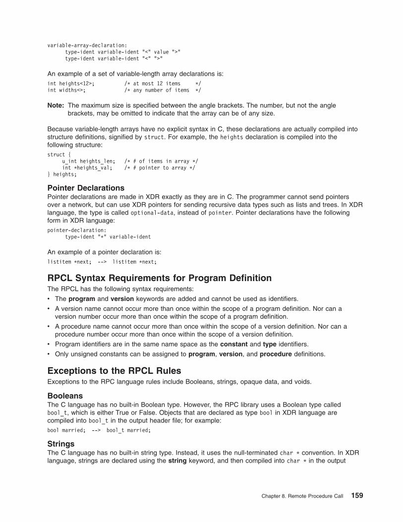
variable-array-declaration:
type-ident variable-ident "<" value ">"
type-ident variable-ident "<" ">"
An example of a set of variable-length array declarations is:
int heights<12>; /* at most 12 items */
int widths<>; /* any number of items */
Note: The maximum size is specified between the angle brackets. The number, but not the angle
brackets, may be omitted to indicate that the array can be of any size.
Because variable-length arrays have no explicit syntax in C, these declarations are actually compiled into
structure definitions, signified by struct. For example, the heights declaration is compiled into the
following structure:
struct {
u_int heights_len; /* # of items in array */
int *heights_val; /* # pointer to array */
} heights;
Pointer Declarations
Pointer declarations are made in XDR exactly as they are in C. The programmer cannot send pointers
over a network, but can use XDR pointers for sending recursive data types such as lists and trees. In XDR
language, the type is called optional-data, instead of pointer. Pointer declarations have the following
form in XDR language:
pointer-declaration:
type-ident "*" variable-ident
An example of a pointer declaration is:
listitem *next; --> listitem *next;
RPCL Syntax Requirements for Program Definition
The RPCL has the following syntax requirements:
v The program and version keywords are added and cannot be used as identifiers.
v A version name cannot occur more than once within the scope of a program definition. Nor can a
version number occur more than once within the scope of a program definition.
v A procedure name cannot occur more than once within the scope of a version definition. Nor can a
procedure number occur more than once within the scope of a version definition.
v Program identifiers are in the same name space as the constant and type identifiers.
v Only unsigned constants can be assigned to program, version, and procedure definitions.
Exceptions to the RPCL Rules
Exceptions to the RPC language rules include Booleans, strings, opaque data, and voids.
Booleans
The C language has no built-in Boolean type. However, the RPC library uses a Boolean type called
bool_t, which is either True or False. Objects that are declared as type bool in XDR language are
compiled into bool_t in the output header file; for example:
bool married; --> bool_t married;
Strings
The C language has no built-in string type. Instead, it uses the null-terminated char * convention. In XDR
language, strings are declared using the string keyword, and then compiled into char * in the output
Chapter 8. Remote Procedure Call 159
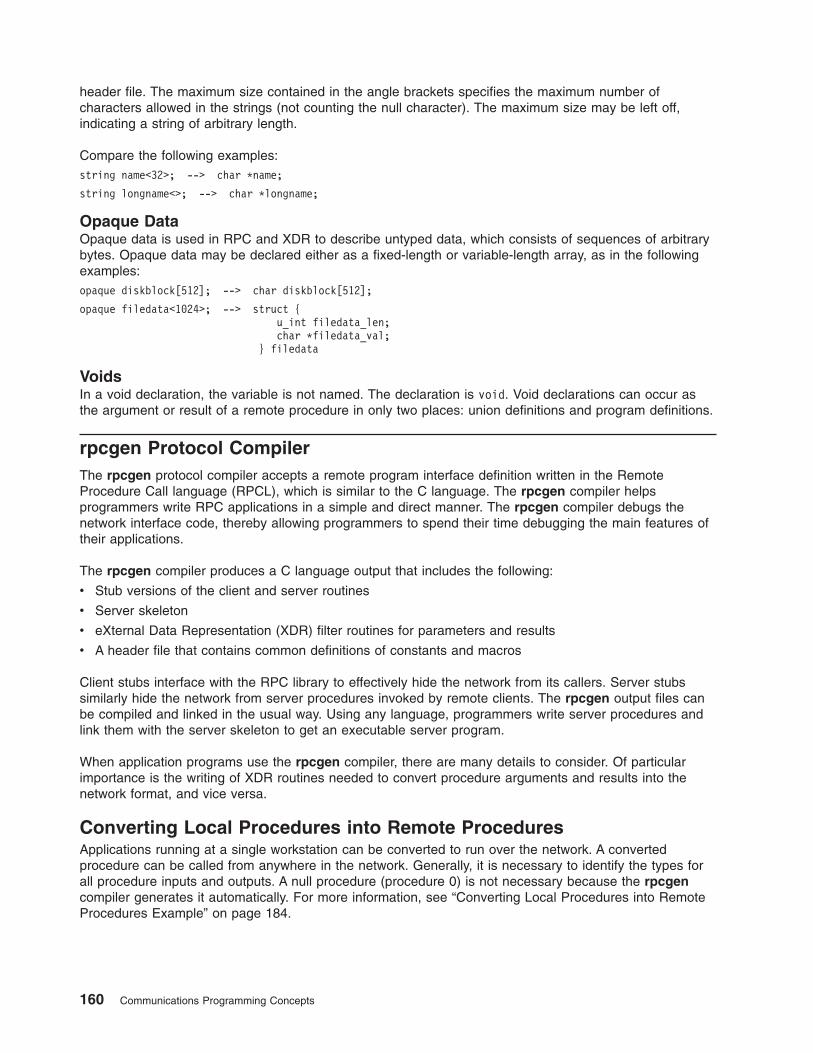
header file. The maximum size contained in the angle brackets specifies the maximum number of
characters allowed in the strings (not counting the null character). The maximum size may be left off,
indicating a string of arbitrary length.
Compare the following examples:
string name<32>; --> char *name;
string longname<>; --> char *longname;
Opaque Data
Opaque data is used in RPC and XDR to describe untyped data, which consists of sequences of arbitrary
bytes. Opaque data may be declared either as a fixed-length or variable-length array, as in the following
examples:
opaque diskblock[512]; --> char diskblock[512];
opaque filedata<1024>; --> struct {
u_int filedata_len;
char *filedata_val;
} filedata
Voids
In a void declaration, the variable is not named. The declaration is void. Void declarations can occur as
the argument or result of a remote procedure in only two places: union definitions and program definitions.
rpcgen Protocol Compiler
The rpcgen protocol compiler accepts a remote program interface definition written in the Remote
Procedure Call language (RPCL), which is similar to the C language. The rpcgen compiler helps
programmers write RPC applications in a simple and direct manner. The rpcgen compiler debugs the
network interface code, thereby allowing programmers to spend their time debugging the main features of
their applications.
The rpcgen compiler produces a C language output that includes the following:
v Stub versions of the client and server routines
v Server skeleton
v eXternal Data Representation (XDR) filter routines for parameters and results
v A header file that contains common definitions of constants and macros
Client stubs interface with the RPC library to effectively hide the network from its callers. Server stubs
similarly hide the network from server procedures invoked by remote clients. The rpcgen output files can
be compiled and linked in the usual way. Using any language, programmers write server procedures and
link them with the server skeleton to get an executable server program.
When application programs use the rpcgen compiler, there are many details to consider. Of particular
importance is the writing of XDR routines needed to convert procedure arguments and results into the
network format, and vice versa.
Converting Local Procedures into Remote Procedures
Applications running at a single workstation can be converted to run over the network. A converted
procedure can be called from anywhere in the network. Generally, it is necessary to identify the types for
all procedure inputs and outputs. A null procedure (procedure 0) is not necessary because the rpcgen
compiler generates it automatically. For more information, see “Converting Local Procedures into Remote
Procedures Example” on page 184.
160 Communications Programming Concepts
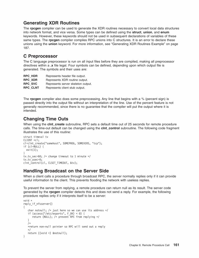
Generating XDR Routines
The rpcgen compiler can be used to generate the XDR routines necessary to convert local data structures
into network format, and vice versa. Some types can be defined using the struct, union, and enum
keywords. However, these keywords should not be used in subsequent declarations of variables of these
same types. The rpcgen compiler compiles RPC unions into C structures. It is an error to declare these
unions using the union keyword. For more information, see “Generating XDR Routines Example” on page
187.
C Preprocessor
The C language preprocessor is run on all input files before they are compiled, making all preprocessor
directives within a .x file legal. Four symbols can be defined, depending upon which output file is
generated. The symbols and their uses are:
RPC_HDR Represents header file output.
RPC_XDR Represents XDR routine output.
RPC_SVC Represents server skeleton output.
RPC_CLNT Represents client stub output.
The rpcgen compiler also does some preprocessing. Any line that begins with a % (percent sign) is
passed directly into the output file without an interpretation of the line. Use of the percent feature is not
generally recommended, since there is no guarantee that the compiler will put the output where it is
intended.
Changing Time Outs
When using the clnt_create subroutine, RPC sets a default time out of 25 seconds for remote procedure
calls. The time-out default can be changed using the clnt_control subroutine. The following code fragment
illustrates the use of this routine:
struct timeval tv
CLIENT *cl;
cl=clnt_create("somehost", SOMEPROG, SOMEVERS, "tcp");
if (cl=NULL) {
exit(1);
}
tv.tv_sec=60; /* change timeout to 1 minute */
tv.tv_usec=0;
clnt_control(cl, CLSET_TIMEOUT, &tv);
Handling Broadcast on the Server Side
When a client calls a procedure through broadcast RPC, the server normally replies only if it can provide
useful information to the client. This prevents flooding the network with useless replies.
To prevent the server from replying, a remote procedure can return null as its result. The server code
generated by the rpcgen compiler detects this and does not send a reply. For example, the following
procedure replies only if it interprets itself to be a server:
void *
reply_if_nfsserver()
{
char notnull; /* just here so we can use its address */
if {access("/etc/exports", F_OK) < 0) {
return (NULL); /* prevent RPC from replying */
}
/*
*return non-null pointer so RPC will send out a reply
*/
return ((void *) ¬null);
}
Chapter 8. Remote Procedure Call 161
If a procedure returns type void, the server must return a nonnull pointer in order for RPC to reply.
Other Information Passed to Server Procedures
Server procedures often want more information about a remote procedure call than just its arguments. For
example, getting authentication information is important to procedures that implement some level of
security. This additional information is supplied to the server procedure as a second argument. The
following example program that allows only root users to print a message on the console, demonstrates
the use of the second argument:
int *
printmessage_1(msg, rq)
char **msg;
struct svc_req *rq;
{
static in result; /* Must be static */
FILE *f;
struct authunix_parms *aup;
aup=(struct authunix_parms *)rq->rq_clntcred;
if (aup->aup_uid !=0) {
result=0;
return (&result);
}
/*
*Same code as before.
*/
}
List of RPC Programming References
The list includes:
v “Subroutines and Macros”
v “Examples” on page 165
Subroutines and Macros
The list of subroutines and macros is arranged by function:
v “Authenticating Remote Procedure Calls”
v “Managing the Client” on page 163
v “Managing the Server” on page 164
v “Using RPC Utilities” on page 165
v “Using DES Interface to the keyserv Daemon” on page 165
v “Interfacing to the portmap Daemon” on page 165
v “Describing and Encoding Remote Procedure Calls” on page 165
Authenticating Remote Procedure Calls
RPC provides these subroutines and macros for creating and destroying authentication information:
authnone_create Creates null authentication information.
authunix_create Creates an authentication handle with operating system permissions.
authunix_create_default Sets the authentication to the default.
authdes_create Enables the use of DES from the client side.
authdes_getucred Maps a DES credential into a UNIX credential.
auth_destroy Destroys authentication information.
162 Communications Programming Concepts
Managing the Client
RPC provides subroutines and macros for the following client management tasks:
v “Creating an RPC Client for a Remote Program”
v “Changing or Retrieving Client Information”
v “Destroying a Client RPC Handle”
v “Broadcasting a Remote Procedure Call”
v “Calling a Remote Procedure”
v “Freeing Memory Allocated by RPC and XDR”
v “Handling Client Errors”
Creating an RPC Client for a Remote Program:
clntraw_create Creates a sample RPC client handle for simulation.
clnttcp_create Creates a Transmission Control Protocol/Internet Protocol (TCP/IP) client transport handle.
clntudp_create Creates a User Datagram Protocol/Internet Protocol (UDP/IP) client transport handle.
clnt_create Creates a generic client transport handle.
Changing or Retrieving Client Information:
clnt_control Changes or retrieves information about a client object.
Destroying a Client RPC Handle:
clnt_destroy Destroys a client’s RPC handle.
Broadcasting a Remote Procedure Call:
clnt_broadcast Broadcasts a remote procedure call to all network hosts.
Calling a Remote Procedure:
callrpc Calls the remote procedure on the machine associated with the host parameter.
clnt_call Calls the remote procedure associated with the clnt parameter.
Freeing Memory Allocated by RPC and XDR:
clnt_freeres Frees memory allocated by RPC and XDR.
Handling Client Errors:
clnt_pcreateerror Identifies why a client RPC handle was not created.
clnt_perrno Specifies the condition of the stat parameter.
clnt_perror Determines why a remote procedure call failed.
clnt_geterr Copies error information from a client transport handle.
clnt_spcreateerror Identifies why a client RPC handle was not created.
clnt_sperrno Specifies the condition of the stat parameter.
clnt_sperror Indicates why a remote procedure call failed.
Chapter 8. Remote Procedure Call 163
Managing the Server
RPC provides subroutines and macros for the following server management tasks:
v “Creating an RPC Service Transport Handle”
v “Destroying an RPC Service Transport Handle”
v “Registering and Unregistering RPC Procedures and Handles”
v “Handling an RPC Request”
v “Handling Server Errors”
Creating an RPC Service Transport Handle:
svcraw_create Creates a sample RPC service handle for simulation.
svctcp_create Creates a TCP/IP service transport handle.
svcudp_create Creates a UDP/IP service transport handle.
svcfd_create Creates a service on any open file descriptor.
Destroying an RPC Service Transport Handle:
svc_destroy Destroys a service transport handle.
Registering and Unregistering RPC Procedures and Handles:
registerrpc Registers a procedure with the RPC service.
xprt_register Registers an RPC service transport handle.
xprt_unregister Removes an RPC service transport handle.
svc_register Maps a remote procedure.
svc_unregister Removes mappings between procedures and objects.
Handling an RPC Request:
svc_run Signals a wait for the arrival of RPC requests.
svc_getreqset Services an RPC request.
svc_getargs Decodes the arguments of an RPC request.
svc_sendreply Sends back the results of a remote procedure call.
svc_freeargs Frees data allocated by the RPC and XDR system.
svc_getcaller Gets the network address of the caller of a procedure.
Handling Server Errors:
svcerr_auth Indicates that the remote procedure call cannot be completed due to an authentication
error.
svcerr_decode Indicates that the parameters of a request cannot be decoded.
svcerr_noproc Indicates that the remote procedure call cannot be completed because the program cannot
support the requested procedure.
svcerr_noprog Indicates that the remote procedure call cannot be completed because the program is not
registered.
svcerr_progvers Indicates that the remote procedure call cannot be completed because the program version
is not registered.
svcerr_systemerr Indicates that the remote procedure call cannot be completed due to an error not covered
by any protocol.
svcerr_weakauth Indicates that the remote procedure call cannot be completed due to insufficient
authentication security parameters.
164 Communications Programming Concepts
Using RPC Utilities
host2netname Converts a host name to a network name.
netname2host Converts a network name to a host name.
netname2user Converts a network name to a user ID.
user2netname Converts a user ID to a network name.
getnetname Installs the network name of the caller in the array.
get_myaddress Gets the user’s IP address.
getrpcent, getrpcbyname,
getrpcbynumber, setrpcent, or
endrpcent
Accesses the /etc/rpc file.
rtime Returns the remote time in the timeval structure.
Using DES Interface to the keyserv Daemon
key_decryptsession Decrypts a server network name and a DES key.
key_encryptsession Encrypts a server network name and a DES key.
key_gendes Requests a secure conversation key from the keyserv daemon.
key_setsecret Sets the key for the user ID of the calling process.
Interfacing to the portmap Daemon
pmap_getmaps Returns a list of the current RPC port mappings.
pmap_getport Requests the port number on which a service waits.
pmap_rmtcall Instructs the portmap daemon to make an RPC.
pmap_set Maps an RPC to a port.
pmap_unset Destroys the mapping between the RPC and the port.
xdr_pmap Describes parameters for portmap procedures.
xdr_pmaplist Describes a list of port mappings externally.
Describing and Encoding Remote Procedure Calls
RPC provides subroutines for describing and encoding RPC call and reply messages, authentication, and
port mappings:
xdr_accepted_reply Encodes RPC reply messages.
xdr_authunix_parms Describes UNIX-style credentials.
xdr_callhdr Describes RPC call header messages.
xdr_callmsg Describes RPC call messages.
xdr_opaque_auth Describes RPC authentication messages.
xdr_rejected_reply Describes RPC message rejection replies.
xdr_replymsg Describes RPC message replies.
Examples
v “Using UNIX Authentication Example” on page 166
v “DES Authentication Example” on page 168
v “Using the Highest Layer of RPC Example” on page 170
v “Using the Intermediate Layer of RPC Example” on page 170
v “Using the Lowest Layer of RPC Example” on page 171
v “Showing How RPC Passes Arbitrary Data Types Example” on page 175
v “Using Multiple Program Versions Example” on page 176
v “Broadcasting a Remote Procedure Call Example” on page 177
v “Using the select Subroutine Example” on page 178
Chapter 8. Remote Procedure Call 165
v “rcp Process on TCP Example” on page 178
v “RPC Callback Procedures Example” on page 180
v “RPC Language ping Program Example” on page 183
v “Converting Local Procedures into Remote Procedures Example” on page 184
v “Generating XDR Routines Example” on page 187
Using UNIX Authentication Example
This example shows how UNIX authentication works on both the client and server sides.
UNIX Authentication on the Client Side
To use UNIX authentication, the programmer first creates the Remote Procedure Call (RPC) client handle
and then sets the authentication parameter.
The RPC client handle is created as follows:
clnt = clntudp_create (address, prognum, versnum, wait, sockp)
The UNIX authentication parameter is set as follows:
clnt->cl_auth = authunix_create_default();
Each remote procedure call associated with the client (clnt) then carries the following UNIX-style
authentication credentials structure:
/*
* UNIX style credentials.
*/
struct authunix_parms {
u_long aup_time; /* credentials creation time */
char *aup_machname; /* host name where client is */
int aup_uid; /* client’s UNIX effective uid */
int aup_gid; /* client’s current group id */
u_int aup_len; /* element length of aup_gids */
int *aup_gids; /* array of groups user is in */
};
The authunix_create_default subroutine sets these fields by invoking the appropriate subroutines. The
UNIX-style authentication is valid until destroyed with the following routine:
auth_destroy(clnt->cl_auth);
UNIX Authentication on the Server Side
This example shows how to use UNIX authorization on the server side.
The following is a structure definition of a request handle passed to a service dispatch routine at the
server:
/*
* An RPC Service request
*/
struct svc_req {
u_long rq_prog; /* service program number */
u_long rq_vers; /* service protocol vers num */
u_long rq_proc; /* desired procedure number */
struct opaque_auth rq_cred; /* raw credentials from wire */
caddr_t rq_clntcred; /* credentials (read only) */
};
Except for the style or flavor of authentication credentials, the rq_cred routine is opaque.
166 Communications Programming Concepts
/*
* Authentication info. Mostly opaque to the programmer.
*/
struct opaque_auth {
enum_t oa_flavor; /* style of credentials */
caddr_t oa_base; /* address of more auth stuff */
u_int oa_length; /* not to exceed MAX_AUTH_BYTES */
};
Before passing a request to the service dispatch routine, RPC guarantees:
v The request’s rq_cred field is in an acceptable form. Therefore, the service implementor may inspect the
request’s rq_cred.oa_flavor to determine which style of authentication the caller used. The service
implementor may also wish to inspect the other rq_cred fields if the authentication style is not one of the
styles supported by the RPC package.
v The request’s rq_clntcred field is either null or points to a well-formed structure that corresponds to a
supported style of authentication credentials. The rq_clntcred field can currently be set as a pointer to
an authunix_parms structure for UNIX-style authentication. If rq_clntcred is null, the service
implementor can inspect the other opaque fields of the rq_cred credential for any new types of
authentication that may be unknown to the RPC package.
The following example uses UNIX authentication on the server side. Here, the remote users service
example is extended so that it computes results for all users except user ID (UID) 16:
nuser(rqstp, transp)
struct svc_req *rqstp;
SVCXPRT *transp;
{
struct authunix_parms *unix_cred;
int uid;
unsigned long nusers;
/*
* we don’t care about authentication for null proc
*/
if (rqstp->rq_proc == NULLPROC) {
if (!svc_sendreply(transp, xdr_void, 0)) {
fprintf(stderr, "can’t reply to RPC call\n");
return (1);
}
return;
}
/*
* now get the uid
*/
switch (rqstp->rq_cred.oa_flavor) {
case AUTH_UNIX:
unix_cred =
(struct authunix_parms *)rqstp->rq_clntcred;
uid = unix_cred->aup_uid;
break;
case AUTH_NULL:
default:
svcerr_weakauth(transp);
return;
}
switch (rqstp->rq_proc) {
case RUSERSPROC_NUM:
/*
* make sure caller is allowed to call this proc
*/
if (uid == 16) {
svcerr_systemerr(transp);
return;
}
/*
Chapter 8. Remote Procedure Call 167
* Code here to compute the number of users
* and assign it to the variable nusers
*/
if (!svc_sendreply(transp, xdr_u_long, &nusers)) {
fprintf(stderr, "can’t reply to RPC call\n");
return (1);
}
return;
default:
svcerr_noproc(transp);
return;
}
}
DES Authentication Example
This example illustrates how Data Encryption Standard (DES) authentication works on both the client side
and the server side.
DES Authentication on the Client Side
To use DES authentication, the client first sets its authentication handle as follows:
cl->cl_auth =
authdes_create(servername, 60, &server_addr, NULL);
The first argument (servername) to the authdes_create routine is the network name, or net name, of the
owner of the server process. Typically, server processes are root processes. The net name can be derived
using the following call:
char servername[MAXNETNAMELEN];
host2netname(servername, rhostname, NULL);
The rhostname parameter is the host name of the machine on which the server process is running. The
host2netname routine supplies the servername that will contain this net name for the root process. If the
server process is run by a regular user, the user2netname routine can be called instead.
The following example illustrates a server process with the same user ID as the client:
char servername[MAXNETNAMELEN];
user2netname(servername, getuid(), NULL);
The user2netname and host2netname routines identify the naming domain at the server location. The
NULL parameter in this example means that the local domain name should be used.
The second argument (60) to the authdes_create routine identifies the lifetime of the credential, which is
60 seconds. This means the credential has 60 seconds until expiration. The server Remote Procedure Call
(RPC) subsystem does not grant either a second request within the 60-second lifetime or requests made
after the credential has expired.
The third argument (&server_addr) to the authdes_create routine is the address of the host with which to
synchronize. DES authentication requires that the server and client agree on the time. The time is
determined by the server when it receives the address. If the server and client times are already
synchronized, the argument can be set to null.
The final argument (NULL) to the authdes_create routine is the address of a DES encryption key that is
used to encrypt time stamps and data. Because this argument is null, a random key is chosen. The
programmer can get the encryption key from the ah_key field of the authentication handle.
168 Communications Programming Concepts
DES Authentication on the Server Side
The following example illustrates DES authentication on the server side. The server side is simpler than
the client side. This example uses AUTH_DES instead of AUTH_UNIX:
#include <sys/time.h>
#include <rpc/auth_des.h>
...
...
nuser(rqstp, transp)
struct svc_req *rqstp;
SVCXPRT *transp;
{
struct authdes_cred *des_cred;
int uid;
int gid;
int gidlen;
int gidlist[10];
/*
* we don’t care about authentication for null proc
*/
if (rqstp->rq_proc == NULLPROC) {
/* same as before */
}
/*
* now get the uid
*/
switch (rqstp->rq_cred.oa_flavor) {
case AUTH_DES:
des_cred =
(struct authdes_cred *) rqstp->rq_clntcred;
if (! netname2user(des_cred->adc_fullname.name,
&uid, &gid, &gidlen, gidlist))
{
fprintf(stderr, "unknown user: %s\n",
des_cred->adc_fullname.name);
svcerr_systemerr(transp);
return;
}
break;
case AUTH_NULL:
default:
svcerr_weakauth(transp);
return;
}
/*
* The rest is the same as UNIX-style authentication
*/
switch (rqstp->rq_proc) {
case RUSERSPROC_NUM:
/*
* make sure caller is allowed to call this proc
*/
if (uid == 16) {
svcerr_systemerr(transp);
return;
}
/*
* Code here to compute the number of users
* and assign it to the variable nusers
*/
if (!svc_sendreply(transp, xdr_u_long, &nusers)) {
fprintf(stderr, "can’t reply to RPC call\n");
return (1);
}
return;
Chapter 8. Remote Procedure Call 169
default:
svcerr_noproc(transp);
return;
}
}
Note: The netname2user routine, which is the inverse of the user2netname routine, converts a network
ID to a user ID. The netname2user routine also supplies group IDs, which are not used in this
example but may be useful in other programs.
Using the Highest Layer of RPC Example
The following example shows how a program calls the Remote Procedure Call (RPC) library rnusers
routine to determine how many users are logged in to a remote workstation:
#include <stdio.h>
main(argc, argv)
int argc;
char **argv;
{
int num;
if (argc != 2) {
fprintf(stderr, "usage: rnusers hostname\n");
exit(1);
}
if ((num = rnusers(argv[1])) < 0) {
fprintf(stderr, "error: rnusers\n");
exit(-1);
}
printf("%d users on %s\n", num, argv[1]);
exit(0);
}
/* to compile: cc -o rnusers rnusers.c -lrpcsvc */
Using the Intermediate Layer of RPC Example
The following example shows a simple interface that makes explicit remote procedure calls using the
callrpc routine at the intermediate layer of Remote Procedure Call (RPC). The interface can be used on
both the client and server sides.
Intermediate Layer of RPC on the Server Side
Normally, the server registers each procedure, and then goes into an infinite loop waiting to service
requests. Because there is only a single procedure to register, the main body of the server message would
look like the following:
#include <stdio.h>
#include <rpc/rpc.h>
#include <utmp.h>
#include <rpcsvc/rusers.h>
char *nuser();
main()
{
registerrpc(RUSERSPROG, RUSERSVERS, RUSERSPROC_NUM,
nuser, xdr_void, xdr_u_long);
svc_run(); /* Never returns */
fprintf(stderr, "Error: svc_run returned!\n");
exit(1);
}
The registerrpc routine registers a C procedure as corresponding to a given RPC procedure number. The
first three parameters, RUSERSPROG, RUSERSVERS, and RUSERSPROC_NUM, specify the program, version, and
procedure numbers of the remote procedure to be registered. The nuser parameter is the name of the
170 Communications Programming Concepts
local procedure that implements the remote procedure, and the xdr_void and xdr_u_long parameters are
the eXternal Data Representation (XDR) filters for the remote procedure’s arguments and results,
respectively.
Intermediate Layer of RPC on the Client Side
#include <stdio.h>
#include <rpc/rpc.h>
#include <utmp.h>
#include <rpcsvc/rusers.h>
main(argc, argv)
int argc;
char **argv;
{
unsigned long nusers;
int stat;
if (argc != 2) {
fprintf(stderr, "usage: nusers hostname\n");
exit(-1);
}
if (stat = callrpc(argv[1],
RUSERSPROG, RUSERSVERS, RUSERSPROC_NUM,
xdr_void, 0, xdr_u_long, &nusers) != 0) {
clnt_perrno(stat);
exit(1);
}
printf("%d users on %s\n", nusers, argv[1]);
exit(0);
}
The callrpc subroutine has eight parameters. The first, host, specifies the name of the remote server
machine. The next three parameters, prognum, versnum, and procnum, specify the program, version, and
procedure numbers. The fifth and sixth parameters, inproc and in, are an XDR filter and an argument to
be encoded and passed to the remote procedure. The final two parameters, outproc and out, are a filter
for decoding the results returned by the remote procedure and a pointer to the place where the
procedure’s results are to be stored. Multiple arguments and results are handled by embedding them in
structures. If the callrpc subroutine completes successfully, it returns zero. Otherwise, it returns a nonzero
value.
Because data types may be represented differently on different machines, the callrpc subroutine needs
both the type of the RPC argument and a pointer to the argument itself. The return value for the
RUSERSPROC_NUM parameter is unsigned long, so the callrpc subroutine has xdr_u_long as its first return
parameter. This parameter specifies that the result is of the unsigned long type. The second return
parameter, &nusers, is a pointer to where the long result is placed. Because the RUSERSPROC_NUM parameter
takes no argument, the argument parameter of the callrpc subroutine is xdr_void.
Using the Lowest Layer of RPC Example
The following is an example of the lowest layer of Remote Procedure Call (RPC) on the server and client
side using the nusers program.
The Lowest Layer of RPC from the Server Side
The server for the nusers program in the following example does the same thing as a program using the
registerrpc subroutine at the highest level of RPC. However, the following is written using the lowest layer
of the RPC package:
#include <stdio.h>
#include <rpc/rpc.h>
#include <utmp.h>
#include <rpcsvc/rusers.h>
Chapter 8. Remote Procedure Call 171
main()
{
SVCXPRT *transp;
int nuser();
transp = svcudp_create(RPC_ANYSOCK);
if (transp == NULL){
fprintf(stderr, "can’t create an RPC server\n");
exit(1);
}
pmap_unset(RUSERSPROG, RUSERSVERS);
if (!svc_register(transp, RUSERSPROG, RUSERSVERS,
nuser, IPPROTO_UDP)) {
fprintf(stderr, "can’t register RUSER service\n");
exit(1);
}
svc_run(); /* Never returns */
fprintf(stderr, "should never reach this point\n");
}
switch (rqstp->rq_proc) {
case NULLPROC:
if (!svc_sendreply(transp, xdr_void, 0))
fprintf(stderr, "can’t reply to RPC call\n");
return;
case RUSERSPROC_NUM:
/*
* Code here to compute the number of users
* and assign it to the nusers variable
*/
if (!svc_sendreply(transp, xdr_u_long, &nusers))
fprintf(stderr, "can’t reply to RPC call\n");
return;
default:
svcerr_noproc(transp);
return;
}
}
First, the server gets a transport handle, which is used for receiving and replying to RPC messages. The
registerrpc routine calls the svcudp_create routine to get a User Datagram Protocol (UDP) handle. If a
more reliable protocol is required, the svctcp_create routine can be called instead. If the argument to the
svcudp_create routine is RPC_ANYSOCK, the RPC library creates a socket on which to receive and reply to
remote procedure calls. Otherwise, the svcudp_create routine expects its argument to be a valid socket
number. If a programmer specifies a socket, it can be bound or unbound. If it is bound to a port by the
programmer, the port numbers of the svcudp_create routine and the clnttcp_create routine (the low-level
client routine) must match.
If the programmer specifies the RPC_ANYSOCK argument, the RPC library routines open sockets. The
svcudp_create and clntudp_create routines cause the RPC library routines to bind the appropriate
socket, if not already bound.
A service may register its port number with the local port mapper service. This is done by specifying a
nonzero protocol number in the svc_register routine. A programmer at the client machine can discover the
server port number by consulting the port mapper at the server workstation. This is done automatically by
specifying a zero port number in the clntudp_create or clnttcp_create routines.
After creating a service transport (SVCXPRT) handle, the next step is to call the pmap_unset routine. If the
nusers server crashed earlier, this routine erases any trace of the crash before restarting. Specifically, the
pmap_unset routine erases the entry for RUSERSPROG from the port mapper’s tables.
172 Communications Programming Concepts
Finally, the program number for nusers is associated with the nuser procedure. The final argument to the
svc_register routine is normally the protocol being used, in this case IPPROTO_UDP. Registration is
performed at the program level, rather than the procedure level.
The nuser user service routine must call and dispatch the appropriate eXternal Data Representation
(XDR) routines based on the procedure number. The nuser routine has two requirements, unlike the
registerrpc routine which performs them automatically. The first is that the NULLPROC procedure
(currently 0) return with no results. This is a simple test for detecting whether a remote program is running.
Second, the subroutine checks for invalid procedure numbers. If one is detected, the svcerr_noproc
routine is called to handle the error.
The user service routine serializes the results and returns them to the RPC caller through the
svc_sendreply routine. The first parameter of this routine is the SVCXPRT handle, the second is the XDR
routine that indicates return data type, and the third is a pointer to the data to be returned.
As an example, a RUSERSPROC_BOOL procedure can be added, which has an nusers argument and
returns a value of True or False, depending on whether there are nusers logged on. The following example
shows this addition:
case RUSERSPROC_BOOL: {
int bool;
unsigned nuserquery;
if (!svc_getargs(transp, xdr_u_int, &nuserquery) {
svcerr_decode(transp);
return;
}
/*
* Code to set nusers = number of users
*/
if (nuserquery == nusers)
bool = TRUE;
else
bool = FALSE;
if (!svc_sendreply(transp, xdr_bool, &bool)) {
fprintf(stderr, "can’t reply to RPC call\n");
return (1);
}
return;
}
The svc_getargs routine takes the following arguments: an SVCXPRT handle, the XDR routine, and a
pointer that indicates where to place the input.
The Lowest Layer of RPC from the Client Side
A programmer using the callrpc routine has control over neither the RPC delivery mechanism nor the
socket used to transport the data. However, the lowest layer of RPC allows the user to adjust these
parameters. The following code can be used to request the nusers service:
#include <stdio.h>
#include <rpc/rpc.h>
#include <utmp.h>
#include <rpcsvc/rusers.h>
#include <sys/socket.h>
#include <sys/time.h>
#include <netdb.h>
main(argc, argv)
int argc;
char **argv;
{
struct hostent *hp;
struct timeval pertry_timeout, total_timeout;
struct sockaddr_in server_addr;
Chapter 8. Remote Procedure Call 173
int sock = RPC_ANYSOCK;
register CLIENT *client;
enum clnt_stat clnt_stat;
unsigned long nusers;
if (argc != 2) {
fprintf(stderr, "usage: nusers hostname\n");
exit(-1);
}
if ((hp = gethostbyname(argv[1])) == NULL) {
fprintf(stderr, "can’t get addr for %s\n",argv[1]);
exit(-1);
}
pertry_timeout.tv_sec = 3;
pertry_timeout.tv_usec = 0;
bcopy(hp->h_addr, (caddr_t)&server_addr.sin_addr,
hp->h_length);
server_addr.sin_family = AF_INET;
server_addr.sin_port = 0;
if ((client = clntudp_create(&server_addr, RUSERSPROG,
RUSERSVERS, pertry_timeout, &sock)) == NULL) {
clnt_pcreateerror("clntudp_create");
exit(-1);
}
total_timeout.tv_sec = 20;
total_timeout.tv_usec = 0;
clnt_stat = clnt_call(client, RUSERSPROC_NUM, xdr_void,
0, xdr_u_long, &nusers, total_timeout);
if (clnt_stat != RPC_SUCCESS) {
clnt_perror(client, "rpc");
exit(-1);
}
clnt_destroy(client);
close(sock);
exit(0);
}
The low-level version of the callrpc routine is the clnt_call macro, which takes a CLIENT pointer rather
than a host name. The parameters to the clnt_call macro are a CLIENT pointer, the procedure number,
the XDR routine for serializing the argument, a pointer to the argument, the XDR routine for deserializing
the return value, a pointer to where the return value is to be placed, and the total time in seconds to wait
for a reply. Thus, the number of tries is the time out divided by the clntudp_create time out.
The CLIENT pointer is encoded with the transport mechanism. The callrpc routine uses UDP, thus it calls
the clntudp_create routine to get a CLIENT pointer. To get Transmission Control Protocol (TCP), the
programmer can call the clnttcp_create routine.
The parameters to the clntudp_create routine are the server address, the program number, the version
number, a time-out value (between tries), and a pointer to a socket.
The clnt_destroy call always deallocates the space associated with the client handle. If the RPC library
opened the socket associated with the client handle, the clnt_destroy macro closes it. If the socket was
opened by the programmer, it stays open. In cases where there are multiple client handles using the same
socket, it is possible to destroy one handle without closing the socket that other handles are using.
The stream connection is made when the call to the clntudp_create macro is replaced by a call to the
clnttcp_create routine.
clnttcp_create(&server_addr, prognum, versnum, &sock,
inputsize, outputsize);
174 Communications Programming Concepts
In this example, no time-out argument exists. Instead, the send and receive buffer sizes must be specified.
When the clnttcp_create call is made, a TCP connection is established. All remote procedure calls using
the client handle use the TCP connection. The server side of a remote procedure call using TCP is similar,
except that the svcudp_create routine is replaced by the svctcp_create routine, as follows:
transp = svctcp_create(RPC_ANYSOCK, 0, 0);
The last two arguments to the svctcp_create routine are send and receive sizes, respectively. If 0 is
specified for either of these, the system chooses a reasonable default.
Showing How RPC Passes Arbitrary Data Types Example
The first two examples show how Remote Procedure Call (RPC) handles arbitrary data types.
Passing a Simple User-Defined Structure Example
struct simple {
int a;
short b;
} simple;
callrpc(hostname, PROGNUM, VERSNUM, PROCNUM,
xdr_simple, &simple ...);
The xdr_simple function is written as:
#include <rpc/rpc.h>
xdr_simple(xdrsp, simplep)
XDR *xdrsp;
struct simple *simplep;
{
if (!xdr_int(xdrsp, &simplep->a))
return (0);
if (!xdr_short(xdrsp, &simplep->b))
return (0);
return (1);
}
Passing a Variable-Length Array Example
struct varintarr {
int *data;
int arrlnth;
} arr;
callrpc(hostname, PROGNUM, VERSNUM, PROCNUM,
xdr_varintarr, &arr...);
The xdr_varintarr subroutine is defined as:
xdr_varintarr(xdrsp, arrp)
XDR *xdrsp;
struct varintarr *arrp;
{
return (xdr_array(xdrsp, &arrp->data, &arrp->arrlnth,
MAXLEN, sizeof(int), xdr_int));
}
This routine’s parameters are the eXternal Data Representation (XDR) handle (xdrsp), a pointer to the
array (aarp->data), a pointer to the size of the array (aarp->arrlnth), the maximum allowable array size
(MAXLEN), the size of each array element (sizeof), and an XDR routine for handling each array element
(xdr_int).
Chapter 8. Remote Procedure Call 175
Passing a Fixed-Length Array Example
If the size of the array is known in advance, the programmer can call the xdr_vector subroutine to
serialize fixed-length arrays, as in the following example:
int intarr[SIZE];
xdr_intarr(xdrsp, intarr)
XDR *xdrsp;
int intarr[];
{
int i;
return (xdr_vector(xdrsp, intarr, SIZE, sizeof(int),
xdr_int));
}
Passing Structure with Pointers Example
The following example calls the previously written xdr_simple routine as well as the built-in xdr_string
and xdr_reference functions. The xdr_reference routine chases pointers.
struct finalexample {
char *string;
struct simple *simplep;
} finalexample;
xdr_finalexample(xdrsp, finalp)
XDR *xdrsp;
struct finalexample *finalp;
{
if (!xdr_string(xdrsp, &finalp->string, MAXSTRLEN))
return (0);
if (!xdr_reference(xdrsp, &finalp->simplep,
sizeof(struct simple), xdr_simple);
return (0);
return (1);
}
Using Multiple Program Versions Example
By convention, the first version number of the PROG program is referred to as PROGVERS_ORIG, and
the most recent version is PROGVERS. For example, the programmer can create a new version of the
user program that returns an unsigned short value rather than a long value. If the programmer names this
version RUSERSVERS_SHORT, then the following program permits the server to support both programs:
if (!svc_register(transp, RUSERSPROG, RUSERSVERS_ORIG,
nuser, IPPROTO_TCP)) {
fprintf(stderr, "can’t register RUSER service\n");
exit(1);
}
if (!svc_register(transp, RUSERSPROG, RUSERSVERS_SHORT,
nuser, IPPROTO_TCP)) {
fprintf(stderr, "can’t register RUSER service\n");
exit(1);
}
Both versions can be handled by the same C procedure, as in the following example using the nusers
procedure:
nuser(rqstp, transp)
struct svc_req *rqstp;
SVCXPRT *transp;
{
unsigned long nusers;
unsigned short nusers2;
176 Communications Programming Concepts
switch (rqstp->rq_proc) {
case NULLPROC:
if (!svc_sendreply(transp, xdr_void, 0)) {
fprintf(stderr, "can’t reply to RPC call\n");
return (1);
}
return;
case RUSERSPROC_NUM:
/*
* Code here to compute the number of users
* and assign it to the variable nusers
*/
nusers2 = nusers;
switch (rqstp->rq_vers) {
case RUSERSVERS_ORIG:
if (!svc_sendreply(transp, xdr_u_long,
&nusers)) {
fprintf(stderr,"can’t reply to RPC call\n");
}
break;
case RUSERSVERS_SHORT:
if (!svc_sendreply(transp, xdr_u_short,
&nusers2)) {
fprintf(stderr,"can’t reply to RPC call\n");
}
break;
}
default:
svcerr_noproc(transp);
return;
}
}
Broadcasting a Remote Procedure Call Example
The following example illustrates broadcast Remote Procedure Call (RPC):
#include <rpc/pmap_clnt.h>
...
enum clnt_stat clnt_stat;
...
clnt_stat = clnt_broadcast(prognum, versnum, procnum,
inproc, in, outproc, out, eachresult)
u_long prognum; /* program number */
u_long versnum; /* version number */
u_long procnum; /* procedure number */
xdrproc_t inpro /* xdr routine for args */
caddr_t in; /* pointer to args */
xdrproc_t outproc /* xdr routine for results */
caddr_t out; /* pointer to results */
bool_t (*eachresult)();/* call with each result gotten */
The eachresult procedure is called each time a result is obtained. This procedure returns a Boolean value
that indicates whether the caller wants more responses.
bool_t done;
...
done = eachresult(resultsp, raddr)
caddr_t resultsp;
struct sockaddr_in *raddr; /* Addr of responding machine */
If the done parameter returns a value of True, then broadcasting stops and the clnt_broadcast routine
returns successfully. Otherwise, the routine waits for another response. The request is rebroadcast after a
few seconds of waiting. If no response comes back, the routine returns with a value of RPC_TIMEDOUT.
Chapter 8. Remote Procedure Call 177
Using the select Subroutine Example
The code for the svc_run routine with the select subroutine is as follows:
void
svc_run()
{
fd_set readfds;
int dtbsz = getdtablesize();
for (;;) {
readfds = svc_fds;
switch (select(dtbsz, &readfds, NULL,NULL,NULL)) {
case -1:
if (errno == EINTR)
continue;
perror("select");
return;
case 0:
break;
default:
svc_getreqset(&readfds);
}
}
}
Beginning in AIX 5.2, the maximum number of open file descriptors that an RPC server can use has been
set to 32767 in order to maintain compatability with RPC-server applications built on earlier releases of
AIX. The fd_set type passed into the svc_getreqset subroutine needs to have been compiled with
FD_SETSIZE set to 32767 or larger. Passing in a smaller fd_set variable may result in the passed in
buffer being overrun by the svc_getreqset subroutine.
rcp Process on TCP Example
The following is an example using the rcp process. This example includes an eXternal Data
Representation (XDR) procedure that behaves differently on serialization than on deserialization. The
initiator of the Remote Procedure Call (RPC) snd call takes its standard input and sends it to the rcv
process on the server, which prints the data to standard output. The snd call uses Transmission Control
Protocol (TCP).
The routine follows:
/*
* The xdr routine:
* on decode, read from wire, write onto fp
* on encode, read from fp, write onto wire
*/
#include <stdio.h>
#include <rpc/rpc.h>
xdr_rcp(xdrs, fp)
XDR *xdrs;
FILE *fp;
{
unsigned long size;
char buf[BUFSIZ], *p;
if (xdrs->x_op == XDR_FREE) /* nothing to free */
return 1;
while (1) {
if (xdrs->x_op == XDR_ENCODE) {
if ((size = fread(buf, sizeof(char), BUFSIZ,
fp)) == 0 && ferror(fp)) {
fprintf(stderr, "can’t fread\n");
return (1);
}
178 Communications Programming Concepts
}
p = buf;
if (!xdr_bytes(xdrs, &p, &size, BUFSIZ))
return 0;
if (size == 0)
return 1;
if (xdrs->x_op == XDR_DECODE) {
if (fwrite(buf, sizeof(char),size,fp) != size) {
fprintf(stderr, "can’t fwrite\n");
return (1);
}
}
}
}
/*
* The sender routines
*/
#include <stdio.h>
#include <netdb.h>
#include <rpc/rpc.h>
#include <sys/socket.h>
#include <sys/time.h>
main(argc, argv)
int argc;
char **argv;
{
int xdr_rcp();
int err;
if (argc < 2) {
fprintf(stderr, "usage: %s servername\n", argv[0]);
exit(-1);
}
if ((err = callrpctcp(argv[1], RCPPROG, RCPPROC,
RCPVERS, xdr_rcp, stdin, xdr_void, 0) != 0)) {
clnt_perrno(err);
fprintf(stderr, "can’t make RPC call\n");
exit(1);
}
exit(0);
}
callrpctcp(host, prognum, procnum, versnum, inproc, in,
outproc, out)
char *host, *in, *out;
xdrproc_t inproc, outproc;
{
struct sockaddr_in server_addr;
int socket = RPC_ANYSOCK;
enum clnt_stat clnt_stat;
struct hostent *hp;
register CLIENT *client;
struct timeval total_timeout;
if ((hp = gethostbyname(host)) == NULL) {
fprintf(stderr, "can’t get addr for ’%s’\n", host);
return (-1);
}
bcopy(hp->h_addr, (caddr_t)&server_addr.sin_addr,
hp->h_length);
server_addr.sin_family = AF_INET;
server_addr.sin_port = 0;
if ((client = clnttcp_create(&server_addr, prognum,
versnum, &socket, BUFSIZ, BUFSIZ)) == NULL) {
perror("rpctcp_create");
return (-1);
}
total_timeout.tv_sec = 20;
Chapter 8. Remote Procedure Call 179
total_timeout.tv_usec = 0;
clnt_stat = clnt_call(client, procnum,
inproc, in, outproc, out, total_timeout);
clnt_destroy(client);
return (int)clnt_stat;
}
/*
* The receiving routines
*/
#include <stdio.h>
#include <rpc/rpc.h>
main()
{
register SVCXPRT *transp;
int rcp_service(), xdr_rcp();
if ((transp = svctcp_create(RPC_ANYSOCK,
BUFSIZ, BUFSIZ)) == NULL) {
fprintf("svctcp_create: error\n");
exit(1);
}
pmap_unset(RCPPROG, RCPVERS);
if (!svc_register(transp,
RCPPROG, RCPVERS, rcp_service, IPPROTO_TCP)) {
fprintf(stderr, "svc_register: error\n");
exit(1);
}
svc_run(); /* never returns */
fprintf(stderr, "svc_run should never return\n");
}
rcp_service(rqstp, transp)
register struct svc_req *rqstp;
register SVCXPRT *transp;
{
switch (rqstp->rq_proc) {
case NULLPROC:
if (svc_sendreply(transp, xdr_void, 0) == 0) {
fprintf(stderr, "err: rcp_service");
return (1);
}
return;
case RCPPROC_FP:
if (!svc_getargs(transp, xdr_rcp, stdout)) {
svcerr_decode(transp);
return;
}
if (!svc_sendreply(transp, xdr_void, 0)) {
fprintf(stderr, "can’t reply\n");
return;
}
return (0);
default:
svcerr_noproc(transp);
return;
}
}
RPC Callback Procedures Example
Occasionally, it is useful to have a server become a client and make a Remote Procedure Call (RPC) back
to the process client. For example, with remote debugging, the client is a window system program and the
server is a debugger running on the remote machine. Usually, the user clicks a mouse button at the
debugging window. This step invokes a debugger command that makes a remote procedure call to the
server (where the debugger is actually running), telling it to execute that command. When the debugger
180 Communications Programming Concepts
hits a breakpoint, however, the roles are reversed. The debugger then makes a remote procedure call to
the window program to inform the user that a breakpoint has been reached.
An RPC callback requires a program number to make the remote procedure call on. Because this will be a
dynamically generated program number, it should be in the transient range, 0x40000000 to 0x5fffffff. The
gettransient routine returns a valid program number in the transient range, and registers it with the port
mapper. This routine only talks to the port mapper running on the same machine as the gettransient
routine itself. The call to the pmap_set routine is a test-and-set operation. That is, it indivisibly tests
whether a program number has already been registered, and reserves the number if it has not. On return,
the sockp argument contains a socket that can be used as the argument to an svcudp_create or
svctcp_create routine.
#include <stdio.h>
#include <rpc/rpc.h>
#include <sys/socket.h>
gettransient(proto, vers, sockp)
int proto, vers, *sockp;
{
static int prognum = 0x40000000;
int s, len, socktype;
struct sockaddr_in addr;
switch(proto) {
case IPPROTO_UDP:
socktype = SOCK_DGRAM;
break;
case IPPROTO_TCP:
socktype = SOCK_STREAM;
break;
default:
fprintf(stderr, "unknown protocol type\n");
return 0;
}
if (*sockp == RPC_ANYSOCK) {
if ((s = socket(AF_INET, socktype, 0)) < 0) {
perror("socket");
return (0);
}
*sockp = s;
}
else
s = *sockp;
addr.sin_addr.s_addr = 0;
addr.sin_family = AF_INET;
addr.sin_port = 0;
len = sizeof(addr);
/*
* may be already bound, so don’t check for error
*/
bind(s, &addr, len);
if (getsockname(s, &addr, &len)< 0) {
perror("getsockname");
return (0);
}
while (!pmap_set(prognum++, vers, proto,
ntohs(addr.sin_port))) continue;
return (prognum-1);
}
Note: The call to the ntohs subroutine ensures that the port number in addr.sin_port, which is in
network byte order, is passed in host byte order. The pmap_set subroutine expects host byte order.
The following programs illustrate how to use the gettransient routine. The client makes a remote
procedure call to the server, passing it a transient program number. Then the client waits around to receive
a callback from the server at that program number. The server registers the EXAMPLEPROG program so
Chapter 8. Remote Procedure Call 181
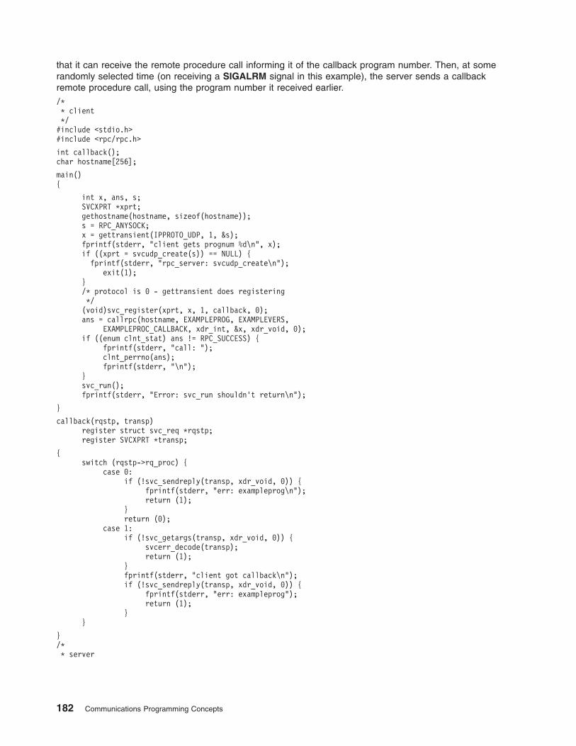
that it can receive the remote procedure call informing it of the callback program number. Then, at some
randomly selected time (on receiving a SIGALRM signal in this example), the server sends a callback
remote procedure call, using the program number it received earlier.
/*
* client
*/
#include <stdio.h>
#include <rpc/rpc.h>
int callback();
char hostname[256];
main()
{
int x, ans, s;
SVCXPRT *xprt;
gethostname(hostname, sizeof(hostname));
s = RPC_ANYSOCK;
x = gettransient(IPPROTO_UDP, 1, &s);
fprintf(stderr, "client gets prognum %d\n", x);
if ((xprt = svcudp_create(s)) == NULL) {
fprintf(stderr, "rpc_server: svcudp_create\n");
exit(1);
}
/* protocol is 0 - gettransient does registering
*/
(void)svc_register(xprt, x, 1, callback, 0);
ans = callrpc(hostname, EXAMPLEPROG, EXAMPLEVERS,
EXAMPLEPROC_CALLBACK, xdr_int, &x, xdr_void, 0);
if ((enum clnt_stat) ans != RPC_SUCCESS) {
fprintf(stderr, "call: ");
clnt_perrno(ans);
fprintf(stderr, "\n");
}
svc_run();
fprintf(stderr, "Error: svc_run shouldn’t return\n");
}
callback(rqstp, transp)
register struct svc_req *rqstp;
register SVCXPRT *transp;
{
switch (rqstp->rq_proc) {
case 0:
if (!svc_sendreply(transp, xdr_void, 0)) {
fprintf(stderr, "err: exampleprog\n");
return (1);
}
return (0);
case 1:
if (!svc_getargs(transp, xdr_void, 0)) {
svcerr_decode(transp);
return (1);
}
fprintf(stderr, "client got callback\n");
if (!svc_sendreply(transp, xdr_void, 0)) {
fprintf(stderr, "err: exampleprog");
return (1);
}
}
}
/*
* server
182 Communications Programming Concepts
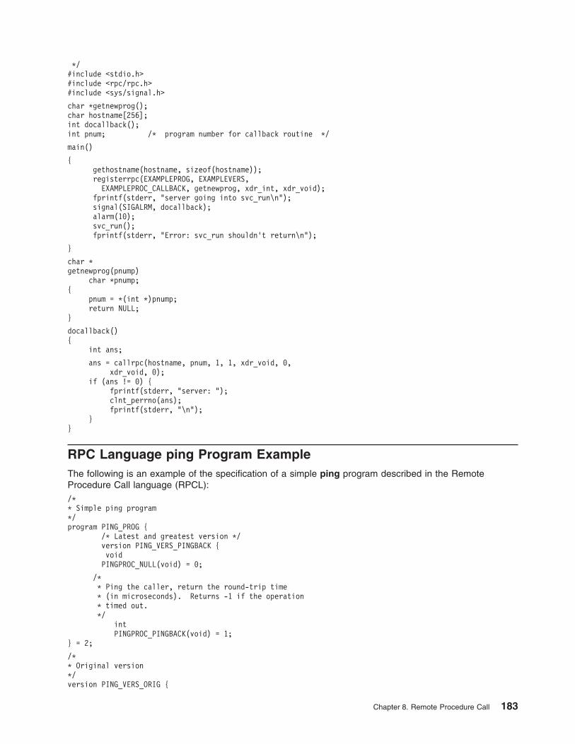
*/
#include <stdio.h>
#include <rpc/rpc.h>
#include <sys/signal.h>
char *getnewprog();
char hostname[256];
int docallback();
int pnum; /* program number for callback routine */
main()
{
gethostname(hostname, sizeof(hostname));
registerrpc(EXAMPLEPROG, EXAMPLEVERS,
EXAMPLEPROC_CALLBACK, getnewprog, xdr_int, xdr_void);
fprintf(stderr, "server going into svc_run\n");
signal(SIGALRM, docallback);
alarm(10);
svc_run();
fprintf(stderr, "Error: svc_run shouldn’t return\n");
}
char *
getnewprog(pnump)
char *pnump;
{
pnum = *(int *)pnump;
return NULL;
}
docallback()
{
int ans;
ans = callrpc(hostname, pnum, 1, 1, xdr_void, 0,
xdr_void, 0);
if (ans != 0) {
fprintf(stderr, "server: ");
clnt_perrno(ans);
fprintf(stderr, "\n");
}
}
RPC Language ping Program Example
The following is an example of the specification of a simple ping program described in the Remote
Procedure Call language (RPCL):
/*
* Simple ping program
*/
program PING_PROG {
/* Latest and greatest version */
version PING_VERS_PINGBACK {
void
PINGPROC_NULL(void) = 0;
/*
* Ping the caller, return the round-trip time
* (in microseconds). Returns -1 if the operation
* timed out.
*/
int
PINGPROC_PINGBACK(void) = 1;
} = 2;
/*
* Original version
*/
version PING_VERS_ORIG {
Chapter 8. Remote Procedure Call 183
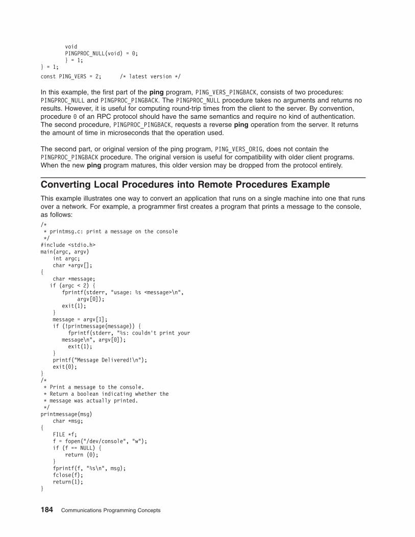
void
PINGPROC_NULL(void) = 0;
} = 1;
} = 1;
const PING_VERS = 2; /* latest version */
In this example, the first part of the ping program, PING_VERS_PINGBACK, consists of two procedures:
PINGPROC_NULL and PINGPROC_PINGBACK. The PINGPROC_NULL procedure takes no arguments and returns no
results. However, it is useful for computing round-trip times from the client to the server. By convention,
procedure 0 of an RPC protocol should have the same semantics and require no kind of authentication.
The second procedure, PINGPROC_PINGBACK, requests a reverse ping operation from the server. It returns
the amount of time in microseconds that the operation used.
The second part, or original version of the ping program, PING_VERS_ORIG, does not contain the
PINGPROC_PINGBACK procedure. The original version is useful for compatibility with older client programs.
When the new ping program matures, this older version may be dropped from the protocol entirely.
Converting Local Procedures into Remote Procedures Example
This example illustrates one way to convert an application that runs on a single machine into one that runs
over a network. For example, a programmer first creates a program that prints a message to the console,
as follows:
/*
* printmsg.c: print a message on the console
*/
#include <stdio.h>
main(argc, argv)
int argc;
char *argv[];
{
char *message;
if (argc < 2) {
fprintf(stderr, "usage: %s <message>\n",
argv[0]);
exit(1);
}
message = argv[1];
if (!printmessage(message)) {
fprintf(stderr, "%s: couldn’t print your
message\n", argv[0]);
exit(1);
}
printf("Message Delivered!\n");
exit(0);
}
/*
* Print a message to the console.
* Return a boolean indicating whether the
* message was actually printed.
*/
printmessage(msg)
char *msg;
{
FILE *f;
f = fopen("/dev/console", "w");
if (f == NULL) {
return (0);
}
fprintf(f, "%s\n", msg);
fclose(f);
return(1);
}
184 Communications Programming Concepts
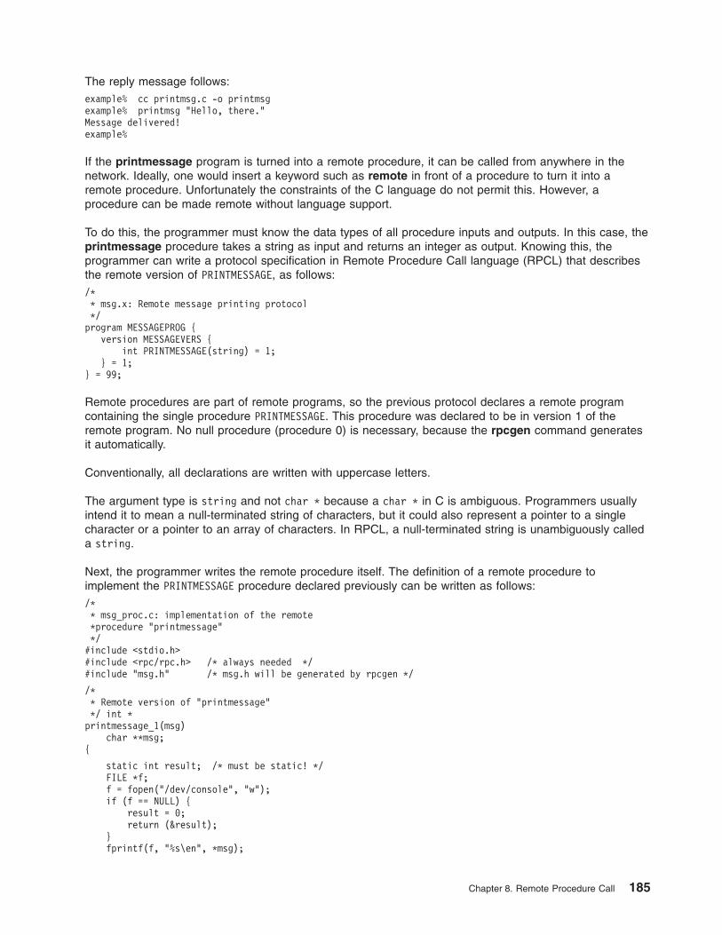
The reply message follows:
example% cc printmsg.c -o printmsg
example% printmsg "Hello, there."
Message delivered!
example%
If the printmessage program is turned into a remote procedure, it can be called from anywhere in the
network. Ideally, one would insert a keyword such as remote in front of a procedure to turn it into a
remote procedure. Unfortunately the constraints of the C language do not permit this. However, a
procedure can be made remote without language support.
To do this, the programmer must know the data types of all procedure inputs and outputs. In this case, the
printmessage procedure takes a string as input and returns an integer as output. Knowing this, the
programmer can write a protocol specification in Remote Procedure Call language (RPCL) that describes
the remote version of PRINTMESSAGE, as follows:
/*
* msg.x: Remote message printing protocol
*/
program MESSAGEPROG {
version MESSAGEVERS {
int PRINTMESSAGE(string) = 1;
} = 1;
} = 99;
Remote procedures are part of remote programs, so the previous protocol declares a remote program
containing the single procedure PRINTMESSAGE. This procedure was declared to be in version 1 of the
remote program. No null procedure (procedure 0) is necessary, because the rpcgen command generates
it automatically.
Conventionally, all declarations are written with uppercase letters.
The argument type is string and not char * because a char * in C is ambiguous. Programmers usually
intend it to mean a null-terminated string of characters, but it could also represent a pointer to a single
character or a pointer to an array of characters. In RPCL, a null-terminated string is unambiguously called
a string.
Next, the programmer writes the remote procedure itself. The definition of a remote procedure to
implement the PRINTMESSAGE procedure declared previously can be written as follows:
/*
* msg_proc.c: implementation of the remote
*procedure "printmessage"
*/
#include <stdio.h>
#include <rpc/rpc.h> /* always needed */
#include "msg.h" /* msg.h will be generated by rpcgen */
/*
* Remote version of "printmessage"
*/ int *
printmessage_1(msg)
char **msg;
{
static int result; /* must be static! */
FILE *f;
f = fopen("/dev/console", "w");
if (f == NULL) {
result = 0;
return (&result);
}
fprintf(f, "%s\en", *msg);
Chapter 8. Remote Procedure Call 185
fclose(f);
result = 1;
return (&result);
}
The declaration of the remote procedure printmessage_1 in this step differs from that of the local
procedure printmessage in the first step, in three ways:
v It takes a pointer to a string instead of the string itself. This is true of all remote procedures, which
always take pointers to their arguments rather than the arguments themselves.
v It returns a pointer to an integer instead of the integer itself. This is also true of remote procedures,
which generally return a pointer to their results.
v It has a _1 appended to its name. Remote procedures called by the rpcgen command are named by
the following rule: the name in the program definition (here PRINTMESSAGE) is converted to all lowercase
letters, and an _ (underscore) and the version number are appended.
Finally, the programmers declare the main client program that will call the remote procedure, as follows:
/*
* rprintmsg.c: remote version of "printmsg.c"
*/
#include <stdio.h>
#include <rpc/rpc.h> /* always needed */
#include "msg.h" /* msg.h will be generated by rpcgen */
main(argc, argv)
int argc;
char *argv[];
{
CLIENT *cl;
int *result;
char *server;
char *message;
if (argc < 3) {
fprintf(stderr,
"usage: %s host message\en", argv[0]);
exit(1);
}
/*
* Save values of command line arguments
*/
server = argv[1];
message = argv[2];
/*
* Create client "handle" used for calling MESSAGEPROG on
* the server designated on the command line. We tell
* the RPC package to use the "tcp" protocol when
* contacting the server.
*/
cl = clnt_create(server, MESSAGEPROG, MESSAGEVERS, "tcp");
if (cl == NULL) {
/*
* Couldn’t establish connection with server.
* Print error message and die.
*/
clnt_pcreateerror(server);
exit(1);
}
/*
* Call the remote procedure "printmessage" on the server
*/
result = printmessage_1(&message, cl);
if (result == NULL) {
/*
* An error occurred while calling the server.
* Print error message and die.
186 Communications Programming Concepts
*/
clnt_perror(cl, server);
exit(1);
}
/*
* Okay, we successfully called the remote procedure.
*/
if (*result == 0) {
/*
* Server was unable to print our message.
* Print error message and die.
*/
fprintf(stderr, "%s: %s couldn’t print your message\n",
argv[0], server);
exit(1);
}
/*
* The message got printed on the server’s console
*/
printf("Message delivered to %s!\n", server);
exit(0);
}
Notes:
1. First a client handle is created using the Remote Procedure Call (RPC) library clnt_create routine.
This client handle is passed to the stub routines that call the remote procedure.
2. The remote procedure printmessage_1 is called exactly the same way as it is declared in the
msg_proc.c program, except for the inserted client handle as the first argument.
The client program rprintmsg and the server program msg_server are compiled as follows:
example% rpcgen msg.x
example% cc rprintmsg.c msg_clnt.c -o rprintmsg
example% cc msg_proc.c msg_svc.c -o msg_server
Before compilation, however, the rpcgen protocol compiler is used to perform the following operations on
the msg.x input file:
v It creates a header file called msg.h that contains #define statements for MESSAGEPROG, MESSAGEVERS,
and PRINTMESSAGE for use in the other modules.
v It creates a client stub routine in the msg_clnt.c file. In this case, there is only one stub routine, the
printmessage_1, which is referred to from the printmsg client program. The name of the output file for
client stub routines is always formed in this way. For example, if the name of the input file is FOO.x, the
client stub’s output file would be called FOO_clnt.c.
v It creates the server program that calls printmessage_1 in the msg_proc.c file. This server program is
named msg_svc.c. The rule for naming the server output file is similar to the previous one. For
example, if an input file is called FOO.x, the output server file is named FOO_svc.c.
Generating XDR Routines Example
The “Converting Local Procedures into Remote Procedures Example” on page 184 demonstrates the
automatic generation of client and server Remote Procedure Call (RPC) code. The rpcgen protocol
compiler may also be used to generate eXternal Data Representation (XDR) routines that convert local
data structures into network format, and vice versa. The following protocol description file presents a
complete RPC service that is a remote directory listing service that uses the rpcgen protocol compiler to
generate not only stub routines, but also XDR routines.
/*
* dir.x: Remote directory listing protocol
*/
const MAXNAMELEN = 255;/* maximum length of a directory entry */
typedef string nametype<MAXNAMELEN>; /* a directory entry */
typedef struct namenode *namelist; /* a link in the listing */
Chapter 8. Remote Procedure Call 187
/*
* A node in the directory listing
*/
struct namenode {
nametype name; /* name of directory entry */
namelist next; /* next entry */
};
/*
* The result of a READDIR operation.
*/
union readdir_res switch (int errno) {
case 0:
namelist list; /* no error: return directory listing */
default:
void; /* error occurred: nothing else to return */
};
/*
* The directory program definition
*/
program DIRPROG {
version DIRVERS {
readdir_res
READDIR(nametype) = 1;
} = 1;
} = 76;
Note: Types (like readdir_res in the previous example) can be defined using the struct, union and
enum keywords, but do not use these keywords in subsequent declarations of variables of those
types. For example, if you define a union, foo, declare it using only foo and not union foo. In fact,
the rpcgen protocol compiler compiles RPC unions into C structures, in which case it is an error to
declare these unions using the union keyword.
Running the rpcgen protocol compiler on the dir.x file creates four output files. Three are the same as
before: header file, client stub routines, and server skeleton. The fourth file contains the XDR routines
necessary for converting the specified data types into XDR format, and vice versa. These are output in the
dir_xdr.c file.
Following is the implementation of the READDIR procedure:
/*
* dir_proc.c: remote readdir implementation
*/
#include <rpc/rpc.h>
#include <sys/dir.h>
#include "dir.h"
extern int errno;
extern char *malloc();
extern char *strdup();
readdir_res *
readdir_1(dirname)
nametype *dirname;
{
DIR *dirp;
struct direct *d;
namelist nl;
namelist *nlp;
static readdir_res res; /* must be static */
/*
* Open directory
*/
dirp = opendir(*dirname);
if (dirp == NULL) {
res.errno = errno;
return (&res);
188 Communications Programming Concepts
}
/*
* Free previous result
*/
xdr_free(xdr_readdir_res, &res);
/*
* Collect directory entries.
* Memory allocated here will be freed by xdr_free
* next time readdir_1 is called
*/
nlp = &res.readdir_res_u.list;
while (d = readdir(dirp)) {
nl = *nlp = (namenode *) malloc(sizeof(namenode));
nl->name = strdup(d->d_name);
nlp = &nl->next;
}
*nlp = NULL;
/*
* Return the result
*/
res.errno = 0;
closedir(dirp);
return (&res);
}
The client side program calls the server as follows:
/*
* rls.c: Remote directory listing client
*/
#include <stdio.h>
#include <rpc/rpc.h> /* always need this */
#include "dir.h" /* will be generated by rpcgen */
extern int errno;
main(argc, argv)
int argc;
char *argv[];
{
CLIENT *cl;
char *server;
char *dir;
readdir_res *result;
namelist nl;
if (argc != 3) {
fprintf(stderr, "usage: %s host directory\n",
argv[0]);
exit(1);
}
/*
* Remember what our command line arguments refer to
*/
server = argv[1];
dir = argv[2];
/*
* Create client "handle" used for calling MESSAGEPROG
* on the server designated on the command line. We
* tell the RPC package to use the "tcp" protocol
* when contacting the server.
*/
cl = clnt_create(server, DIRPROG, DIRVERS, "tcp");
if (cl == NULL) {
/*
* Could not establish connection with server.
Chapter 8. Remote Procedure Call 189
* Print error message and die.
*/
clnt_pcreateerror(server);
exit(1);
}
/*
* Call the remote procedure readdir on the server
*/
result = readdir_1(&dir, cl);
if (result == NULL) {
/*
* An error occurred while calling the server.
* Print error message and die.
*/
clnt_perror(cl, server);
exit(1);
}
/*
* Okay, we successfully called the remote procedure.
*/
if (result->errno != 0) {
/*
* A remote system error occurred.
* Print error message and die.
*/
errno = result->errno;
perror(dir);
exit(1);
}
/*
* Successfully got a directory listing.
* Print it out.
*/
for (nl = result->readdir_res_u.list; nl != NULL;
nl = nl->next) {
printf("%s\en", nl->name);
}
exit(0);
}
Finally, in regard to the rpcgen protocol compiler, the client program and the server procedure can be
tested together as a single program by linking them with each other rather than with client and server
stubs. The procedure calls are executed as ordinary local procedure calls and the program can be
debugged with a local debugger such as dbx. When the program is working, the client program can be
linked to the client stub produced by the rpcgen protocol compiler. The server procedures can be linked to
the server stub produced by the rpcgen protocol compiler.
Note: If you do this, you might want to comment out calls to RPC library routines and have client-side
routines call server routines directly.
190 Communications Programming Concepts
Chapter 9. Sockets
The operating system includes the Berkeley Software Distribution (BSD) interprocess communication (IPC)
facility known as sockets. Sockets are communication channels that enable unrelated processes to
exchange data locally and across networks. A single socket is one end point of a two-way communication
channel.
This chapter discusses the following topics:
v “Sockets Overview”
v “Sockets Interface” on page 193
v “Socket Subroutines” on page 194
v “Socket Header Files” on page 195
v “Socket Communication Domains” on page 196
v “Socket Addresses” on page 198
v “Socket Types and Protocols” on page 201
v “Socket Creation” on page 203
v “Binding Names to Sockets” on page 203
v “Socket Connections” on page 205
v “Socket Options” on page 208
v “Socket Data Transfer” on page 208
v “Socket Shutdown” on page 210
v “IP Multicasts” on page 211
v “Network Address Translation” on page 212
v “Domain Name Resolution” on page 216
v “Socket Examples” on page 218
v “List of Socket Programming References” on page 246
Sockets Overview
In the operating system, sockets have the following characteristics:
v A socket exists only as long as a process holds a descriptor referring to it.
v Sockets are referenced by file descriptors and have qualities similar to those of a character special
device. Read, write, and select operations can be performed on sockets by using the appropriate
subroutines.
v Sockets can be created in pairs, given names, or used to rendezvous with other sockets in a
communication domain, accepting connections from these sockets or exchanging messages with them.
Critical Attributes
Sockets share certain critical attributes that no other IPC mechanisms feature:
v Provide a two-way communication path.
v Include a socket type and one or more associated processes.
v Exist within communication domains.
v Do not require a common ancestor to set up the communication.
Application programs request the operating system to create a socket when one is needed. The operating
system returns an integer that the application program uses to reference the newly created socket. Unlike
© Copyright IBM Corp. 1994, 2005 191

file descriptors, the operating system can create sockets without binding them to a specific destination
address. The application program can choose to supply a destination address each time it uses the
socket.
Sockets Background
Sockets were developed in response to the need for sophisticated interprocess facilities to meet the
following goals:
v Provide access to communications networks such as the Internet.
v Enable communication between unrelated processes residing locally on a single host computer and
residing remotely on multiple host machines.
Sockets provide a sufficiently general interface to allow network-based applications to be constructed
independently of the underlying communication facilities. They also support the construction of distributed
programs built on top of communication primitives.
Note: The socket subroutines serve as the application program interface for Transmission Control
Protocol/Internet Protocol (TCP/IP).
Socket Facilities
Socket subroutines and network library subroutines provide the building blocks for IPC. An application
program must perform the following basic functions to conduct IPC through the socket layer:
v Create and name sockets.
v Accept and make socket connections.
v Send and receive data.
v Shut down socket operations.
v Translate network addresses.
Creating and Naming Sockets
A socket is created with the socket subroutine. This subroutine creates a socket of a specified domain,
type, and protocol. Sockets have different qualities depending on these specifications. A communication
domain indicates the protocol families to be used with the created socket. The socket type defines its
communication properties such as reliability, ordering, and prevention of duplication of messages. Some
protocol families have multiple protocols that support one type of service. To supply a protocol in the
creation of a socket, the programmer must understand the protocol family well enough to know the type of
service each protocol supplies.
An application can bind a name to a socket. The socket names used by most applications are readable
strings. However, the name for a socket that is used within a communication domain is usually a low-level
address. The form and meaning of socket addresses are dependent on the communication domain in
which the socket is created. The socket name is specified by a sockaddr structure (see “Socket Address
Data Structures” on page 195).
Accepting and Making Socket Connections
Sockets can be connected or unconnected. Unconnected sockets are produced by the socket subroutine.
An unconnected socket can yield a connected socket pair by:
v Actively connecting to another socket
v Becoming associated with a name in the communication domain and accepting a connection from
another socket
Other types of sockets, such as datagram sockets, need not establish connections before use.
192 Communications Programming Concepts
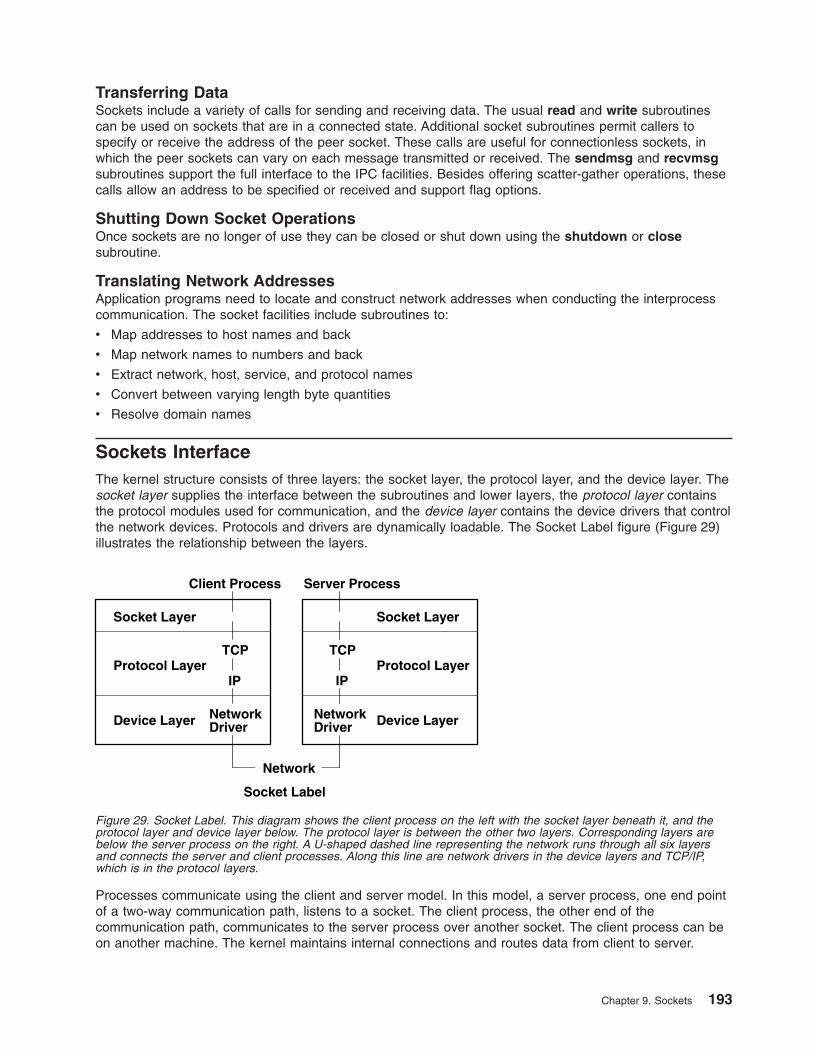
Transferring Data
Sockets include a variety of calls for sending and receiving data. The usual read and write subroutines
can be used on sockets that are in a connected state. Additional socket subroutines permit callers to
specify or receive the address of the peer socket. These calls are useful for connectionless sockets, in
which the peer sockets can vary on each message transmitted or received. The sendmsg and recvmsg
subroutines support the full interface to the IPC facilities. Besides offering scatter-gather operations, these
calls allow an address to be specified or received and support flag options.
Shutting Down Socket Operations
Once sockets are no longer of use they can be closed or shut down using the shutdown or close
subroutine.
Translating Network Addresses
Application programs need to locate and construct network addresses when conducting the interprocess
communication. The socket facilities include subroutines to:
v Map addresses to host names and back
v Map network names to numbers and back
v Extract network, host, service, and protocol names
v Convert between varying length byte quantities
v Resolve domain names
Sockets Interface
The kernel structure consists of three layers: the socket layer, the protocol layer, and the device layer. The
socket layer supplies the interface between the subroutines and lower layers, the protocol layer contains
the protocol modules used for communication, and the device layer contains the device drivers that control
the network devices. Protocols and drivers are dynamically loadable. The Socket Label figure (Figure 29)
illustrates the relationship between the layers.
Processes communicate using the client and server model. In this model, a server process, one end point
of a two-way communication path, listens to a socket. The client process, the other end of the
communication path, communicates to the server process over another socket. The client process can be
on another machine. The kernel maintains internal connections and routes data from client to server.
Client Process
Socket Layer
IP
Device Layer NetworkDriver
Protocol LayerTCP
Server Process
IP
NetworkDriver
TCP
Socket Layer
Device Layer
Protocol Layer
Network
Socket Label
Figure 29. Socket Label. This diagram shows the client process on the left with the socket layer beneath it, and the
protocol layer and device layer below. The protocol layer is between the other two layers. Corresponding layers are
below the server process on the right. A U-shaped dashed line representing the network runs through all six layers
and connects the server and client processes. Along this line are network drivers in the device layers and TCP/IP,
which is in the protocol layers.
Chapter 9. Sockets 193
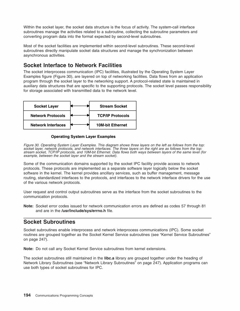
Within the socket layer, the socket data structure is the focus of activity. The system-call interface
subroutines manage the activities related to a subroutine, collecting the subroutine parameters and
converting program data into the format expected by second-level subroutines.
Most of the socket facilities are implemented within second-level subroutines. These second-level
subroutines directly manipulate socket data structures and manage the synchronization between
asynchronous activities.
Socket Interface to Network Facilities
The socket interprocess communication (IPC) facilities, illustrated by the Operating System Layer
Examples figure (Figure 30), are layered on top of networking facilities. Data flows from an application
program through the socket layer to the networking support. A protocol-related state is maintained in
auxiliary data structures that are specific to the supporting protocols. The socket level passes responsibility
for storage associated with transmitted data to the network level.
Some of the communication domains supported by the socket IPC facility provide access to network
protocols. These protocols are implemented as a separate software layer logically below the socket
software in the kernel. The kernel provides ancillary services, such as buffer management, message
routing, standardized interfaces to the protocols, and interfaces to the network interface drivers for the use
of the various network protocols.
User request and control output subroutines serve as the interface from the socket subroutines to the
communication protocols.
Note: Socket error codes issued for network communication errors are defined as codes 57 through 81
and are in the /usr/include/sys/errno.h file.
Socket Subroutines
Socket subroutines enable interprocess and network interprocess communications (IPC). Some socket
routines are grouped together as the Socket Kernel Service subroutines (see “Kernel Service Subroutines”
on page 247).
Note: Do not call any Socket Kernel Service subroutines from kernel extensions.
The socket subroutines still maintained in the libc.a library are grouped together under the heading of
Network Library Subroutines (see “Network Library Subroutines” on page 247). Application programs can
use both types of socket subroutines for IPC.
10M-bit EthernetNetwork Interfaces
TCP/IP Protocols
Stream Socket
Network Protocols
Socket Layer
Operating System Layer Examples
Figure 30. Operating System Layer Examples. This diagram shows three layers on the left as follows from the top:
socket layer, network protocols, and network interfaces. The three layers on the right are as follows from the top:
stream socket, TCP/IP protocols, and 10M-bit Ethernet. Data flows both ways between layers of the same level (for
example, between the socket layer and the stream socket).
194 Communications Programming Concepts
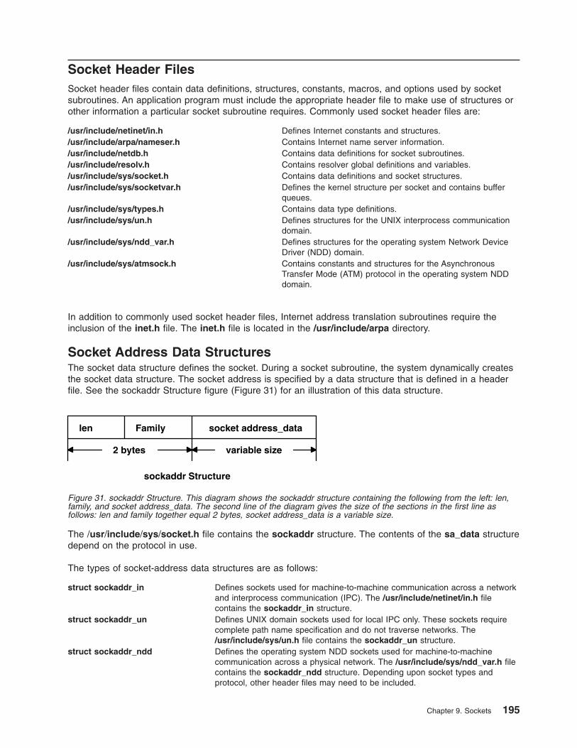
Socket Header Files
Socket header files contain data definitions, structures, constants, macros, and options used by socket
subroutines. An application program must include the appropriate header file to make use of structures or
other information a particular socket subroutine requires. Commonly used socket header files are:
/usr/include/netinet/in.h Defines Internet constants and structures.
/usr/include/arpa/nameser.h Contains Internet name server information.
/usr/include/netdb.h Contains data definitions for socket subroutines.
/usr/include/resolv.h Contains resolver global definitions and variables.
/usr/include/sys/socket.h Contains data definitions and socket structures.
/usr/include/sys/socketvar.h Defines the kernel structure per socket and contains buffer
queues.
/usr/include/sys/types.h Contains data type definitions.
/usr/include/sys/un.h Defines structures for the UNIX interprocess communication
domain.
/usr/include/sys/ndd_var.h Defines structures for the operating system Network Device
Driver (NDD) domain.
/usr/include/sys/atmsock.h Contains constants and structures for the Asynchronous
Transfer Mode (ATM) protocol in the operating system NDD
domain.
In addition to commonly used socket header files, Internet address translation subroutines require the
inclusion of the inet.h file. The inet.h file is located in the /usr/include/arpa directory.
Socket Address Data Structures
The socket data structure defines the socket. During a socket subroutine, the system dynamically creates
the socket data structure. The socket address is specified by a data structure that is defined in a header
file. See the sockaddr Structure figure (Figure 31) for an illustration of this data structure.
The /usr/include/sys/socket.h file contains the sockaddr structure. The contents of the sa_data structure
depend on the protocol in use.
The types of socket-address data structures are as follows:
struct sockaddr_in Defines sockets used for machine-to-machine communication across a network
and interprocess communication (IPC). The /usr/include/netinet/in.h file
contains the sockaddr_in structure.
struct sockaddr_un Defines UNIX domain sockets used for local IPC only. These sockets require
complete path name specification and do not traverse networks. The
/usr/include/sys/un.h file contains the sockaddr_un structure.
struct sockaddr_ndd Defines the operating system NDD sockets used for machine-to-machine
communication across a physical network. The /usr/include/sys/ndd_var.h file
contains the sockaddr_ndd structure. Depending upon socket types and
protocol, other header files may need to be included.
len socket address_data
2 bytes variable size
Family
sockaddr Structure
Figure 31. sockaddr Structure. This diagram shows the sockaddr structure containing the following from the left: len,
family, and socket address_data. The second line of the diagram gives the size of the sections in the first line as
follows: len and family together equal 2 bytes, socket address_data is a variable size.
Chapter 9. Sockets 195
Socket Communication Domains
Sockets that share common communication properties, such as naming conventions and protocol address
formats, are grouped into communication domains. A communication domain is sometimes referred to as
name or address space.
The communication domain includes the following:
v Rules for manipulating and interpreting names
v Collection of related address formats that comprise an address family
v Set of protocols, called the protocol family
Communication domains also consist of two categories, socket types and descriptors. Socket types include
stream, datagram, sequenced packet, raw, and connection-oriented datagram.
Address Formats
An address format indicates what set of rules was used in creating network addresses of a particular
format. For example, in the Internet communication domain, a host address is a 32-bit value that is
encoded using one of four rules based on the type of network on which the host resides.
Each communication domain has different rules for valid socket names and interpretation of names. After a
socket is created, it can be given a name according to the rules of the communication domain in which it
was created. For example, in the UNIX communication domain, sockets are named with operating system
path names. A socket can be named /dev/foo. Sockets normally exchange data only with sockets in the
same communication domain.
Address Families
The socket subroutine takes an address family as a parameter. Specifying an address family indicates to
the system how to interpret supplied addresses. The /usr/include/sys/socket.h and
/usr/include/sys/socketvar.h files define the address families.
A socket subroutine that takes an address family (AF) as a parameter can use AF_UNIX (UNIX), AF_INET
(Internet), AF_NS (Xerox Network Systems), or AF_NDD (Network Device Drivers of the operating sytem)
protocol. These address families are part of the following communication domains:
UNIX Provides socket communication between processes running on the same operating system when an
address family of AF_UNIX is specified. A socket name in the UNIX domain is a string of ASCII
characters whose maximum length depends on the machine in use.
Internet Provides socket communication between a local process and a process running on a remote host
when an address family of AF_INET is specified. The Internet domain requires that Transmission
Control Protocol/Internet Protocol (TCP/IP) be installed on your system. A socket name in the Internet
domain is an Internet address, made up of a 32-bit IP address and a 16-bit port address.
NDD Provides socket communication between a local process and a process running on a remote host
when an address family of AF_NDD is specified. The NDD domain enables applications to run
directly on top of physical networks. This is in contrast to the Internet domain, in which applications
run on top of transport protocols such as TCP, or User Datagram Protocol (UDP). A socket name in
the NDD domain consists of operating system NDD name and a second part that is protocol
dependent.
Communication domains are described by a domain data structure that is loadable. Communication
protocols within a domain are described by a structure that is defined within the system for each protocol
implementation configured. When a request is made to create a socket, the system uses the name of the
communication domain to search linearly the list of configured domains. If the domain is found, the
196 Communications Programming Concepts
domain’s table of supported protocols is consulted for a protocol appropriate for the type of socket being
created or for a specific protocol request. (A wildcard entry may exist for a raw domain.) Should multiple
protocol entries satisfy the request, the first is selected.
UNIX Domain Properties
Characteristics of the UNIX domain are:
Types of sockets In the UNIX domain, the SOCK_STREAM socket type provides pipe-like facilities, while the
SOCK_DGRAM and SOCK_SEQPACKET socket types usually provide reliable message-style
communications.
Naming Socket names are strings and appear in the file system name space through portals.
Passing File Descriptors
In the Unix system it is possible to pass an open file between processes in a couple of ways:
1. From a parent to a child by opening it in the parent and then either fork or exec another process. This
has obvious shortcomings.
2. Between any processes using a Unix domain socket, as described below. This is a more general
technique.
Passing a file descriptor from one process to another means taking an open file in the sending process
and generating another pointer to the file table entry in the receiving process. To pass a file descriptor
from any arbitrary process to another, it is necessary for the processes to be connected with a Unix
domain socket (a socket whose family type is AF_UNIX). Thereafter, one can pass a descriptor from the
sending process by using the sendmsg() system call to the receiving process, which must perform the
recvmsg() system call. These two system calls are the only ones supporting the concept of ″access rights″
which is how descriptors are passed.
Basically “access rights” imply that the owning process has acquired the rights to the corresponding
system resource by opening it. This right is then passed by this process (the sending process) to a
receiving process using the aforesaid system calls. Typically, file descriptors are passed through the
access rights mechanism.
The msghdr structure in sys/socket.h contains the following field:
caddr_t msg_accrights access rights sent/received
The file descriptor is passed through this field of the message header, which is used as a parameter in the
corresponding sendmsg() system call.
Internet Domain Properties
Characteristics of the Internet domain are:
Socket types and protocols The SOCK_STREAM socket type is supported by the Internet TCP protocol; the
SOCK_DGRAM socket type, by the UDP protocol. Each is layered atop the
transport-level IP. The Internet Control Message Protocol (ICMP) is implemented atop
or beside IP and is accessible through a raw socket.
Naming Sockets in the Internet domain have names composed of a 32-bit Internet address
and a 16-bit port number. Options can be used to provide IP source routing or
security options. The 32-bit address is composed of network and host parts; the
network part is variable in size and is frequency encoded. The host part can be
interpreted optionally as a subnet field plus the host on a subnet; this is enabled by
setting a network address mask.
Chapter 9. Sockets 197
Raw access The Internet domain allows a program with root-user authority access to the raw
facilities of IP. These interfaces are modeled as SOCK_RAW sockets. Each raw
socket is associated with one IP protocol number and receives all traffic for that
protocol. This allows administrative and debugging functions to occur and enables
user-level implementations of special-purpose protocols such as inter-gateway routing
protocols.
The Operating System Network Device Driver (NDD) Domain Properties
Characteristics of the operating system NDD domain are:
Socket types and protocols The SOCK_DGRAM socket type is supported by the connectionless datagram
protocols. These include Ethernet, token ring, Fiber Distributed Data Interface (FDDI),
and FCS protocols. This socket type allows applications to send and receive
datagrams directly over these media types. The SOCK_CONN_DGRAM socket type
is supported by connection-oriented datagram protocols. Currently, Asynchronous
Transfer Mode (ATM) is the only protocol defined for this socket type. This socket
type has the property of connection-oriented, unreliable, message delivery service.
Naming Sockets in the NDD domain have names composed of the operating system NDD
name and a second part that is protocol dependent. For example, for ATM, this part
contains a 20-byte destination address and subaddress.
Socket Addresses
Sockets can be named with an address so that processes can connect to them. The socket layer treats an
address as an opaque object. Applications supply and receive addresses as tagged, variable-length byte
strings. Addresses always reside in a memory buffer (mbuf) on entry to the socket layer. A data structure
called a sockaddr (see “Socket Address Data Structures” on page 195) can be used as a template for
referring to the identifying tag of each socket address.
Each address-family implementation includes subroutines for address family-specific operations. When
addresses must be manipulated (for example, to compare them for equality) a pointer to the address (a
sockaddr structure) is used to extract the address family tag. This tag is then used to identify the
subroutine to invoke the desired operation.
Socket Address Storage
Addresses passed by an application program commonly reside in mbufs only long enough for the socket
layer to pass them to the supporting protocol for transfer into a fixed-sized address structure. This occurs,
for example, when a protocol records an address in a protocol control block. The sockaddr structure is
the common means by which the socket layer and network-support facilities exchange addresses. The
size of the generic data array was chosen to be large enough to hold most addresses directly.
Communications domains that support larger addresses may ignore the array size (see “Socket
Communication Domains” on page 196).
v The UNIX communication domain stores file-system path names in mbufs and allows socket names as
large as 108 bytes.
v The Internet communication domain uses a structure that combines an Internet address and a port
number. The Internet protocols reserve space for addresses in an Internet control-block data structure
and free up mbufs that contain addresses after copying their contents.
Socket Addresses in TCP/IP
Transmission Control Protocol/Internet Protocol (Chapter 11, “Transmission Control Protocol/Internet
Protocol,” on page 293) provides a set of 16-bit port numbers within each host. Because each host
assigns port numbers independently, it is possible for ports on different hosts to have the same port
198 Communications Programming Concepts

number. TCP/IP creates the socket address as an identifier that is unique throughout all Internet networks.
TCP/IP concatenates the Internet address of the local host interface with the port number to devise the
Internet socket address.
With TCP/IP, sockets are not tied to a destination address. Applications sending messages can specify a
different destination address for each datagram, if necessary, or they can tie the socket to a specific
destination address for the duration of the connection (see 201).
Because the Internet address is always unique to a particular host on a network, the socket address for a
particular socket on a particular host is unique. Additionally, because each connection is fully specified by
the pair of sockets it joins, every connection between Internet hosts is also uniquely identified.
The port numbers up to 255 are reserved for official Internet services. Port numbers in the range of
256-1023 are reserved for other well-known services that are common on Internet networks. When a client
process needs one of these well-known services at a particular host, the client process sends a service
request to the socket address for the well-known port at the host.
If a process on the host is listening at the well-known port, the server process either services the request
using the well-known port or transfers the connection to another port that is temporarily assigned for the
duration of the connection to the client. Using temporarily-assigned (or secondary) ports frees the
well-known port and allows the host well-known port to handle additional requests concurrently.
The port numbers for well-known ports are listed in the /etc/services file. The port numbers above 1023
are generally used by processes that need a temporary port after an initial service request has been
received. These port numbers are generated randomly and used on a first-come, first-served basis.
Socket Addresses in the Operating System Network Device Driver
(NDD)
In the operating system NDD domain, socket addresses contain the NDD name, which associates the
socket with the local device (or adapter). Socket addresses also contain a protocol-dependent part.
Typically, applications use the bind subroutine to bind a socket to a particular local device and 802.2
service access point (SAP). The information used to bind to a particular NDD and packet type are
specified in the NDD socket address passed into the bind subroutine. After the socket is bound, it can be
used to receive packets for the bound SAP addressed to the local host’s medium access control (MAC)
address (or the broadcast address) for that device. Raw packets can be transmitted using the send,
sendto, and sendmsg socket subroutines.
The protocol-dependent parts of the operating system NDD socket address structure are defined as
follows:
Ethernet The Ethernet NDD sockaddr is defined in the sys/ndd_var.h file. The sockaddr structure name
is sockaddr_ndd_8022. This sockaddr allows you to bind to an Ethernet type number or an
802.2 SAP number. When bound to a particular type or SAP, a socket can be used to receive
packets of that type or SAP. Packets to be transmitted must be complete Ethernet packets that
include the MAC and logical link control (LLC) headers.
Token Ring The token-ring NDD sockaddr is defined in the sys/ndd_var.h file. The sockaddr structure
name is sockaddr_ndd_8022. This sockaddr allows you to bind to an 802.2 SAP number. When
bound to a particular type or SAP, a socket can be used to receive packets of that type or SAP.
Packets to be transmitted must be complete token ring packets that include the MAC and LLC
headers.
FDDI The Fiber Distributed Data Interface (FDDI) NDD sockaddr is defined in the sys/ndd_var.h file.
The sockaddr structure name is sockaddr_ndd_8022. This sockaddr allows you to bind to an
802.2 SAP number. When bound to a particular type or SAP, a socket can be used to receive
packets of that type or SAP. Packets to be transmitted must be complete FDDI packets that
include the MAC and LLC headers.
Chapter 9. Sockets 199
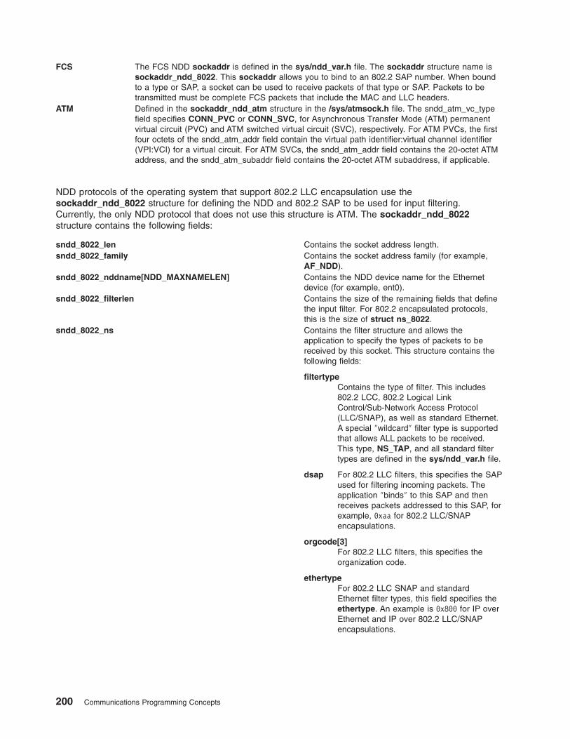
FCS The FCS NDD sockaddr is defined in the sys/ndd_var.h file. The sockaddr structure name is
sockaddr_ndd_8022. This sockaddr allows you to bind to an 802.2 SAP number. When bound
to a type or SAP, a socket can be used to receive packets of that type or SAP. Packets to be
transmitted must be complete FCS packets that include the MAC and LLC headers.
ATM Defined in the sockaddr_ndd_atm structure in the /sys/atmsock.h file. The sndd_atm_vc_type
field specifies CONN_PVC or CONN_SVC, for Asynchronous Transfer Mode (ATM) permanent
virtual circuit (PVC) and ATM switched virtual circuit (SVC), respectively. For ATM PVCs, the first
four octets of the sndd_atm_addr field contain the virtual path identifier:virtual channel identifier
(VPI:VCI) for a virtual circuit. For ATM SVCs, the sndd_atm_addr field contains the 20-octet ATM
address, and the sndd_atm_subaddr field contains the 20-octet ATM subaddress, if applicable.
NDD protocols of the operating system that support 802.2 LLC encapsulation use the
sockaddr_ndd_8022 structure for defining the NDD and 802.2 SAP to be used for input filtering.
Currently, the only NDD protocol that does not use this structure is ATM. The sockaddr_ndd_8022
structure contains the following fields:
sndd_8022_len Contains the socket address length.
sndd_8022_family Contains the socket address family (for example,
AF_NDD).
sndd_8022_nddname[NDD_MAXNAMELEN] Contains the NDD device name for the Ethernet
device (for example, ent0).
sndd_8022_filterlen Contains the size of the remaining fields that define
the input filter. For 802.2 encapsulated protocols,
this is the size of struct ns_8022.
sndd_8022_ns Contains the filter structure and allows the
application to specify the types of packets to be
received by this socket. This structure contains the
following fields:
filtertype
Contains the type of filter. This includes
802.2 LCC, 802.2 Logical Link
Control/Sub-Network Access Protocol
(LLC/SNAP), as well as standard Ethernet.
A special ″wildcard″ filter type is supported
that allows ALL packets to be received.
This type, NS_TAP, and all standard filter
types are defined in the sys/ndd_var.h file.
dsap For 802.2 LLC filters, this specifies the SAP
used for filtering incoming packets. The
application ″binds″ to this SAP and then
receives packets addressed to this SAP, for
example, 0xaa for 802.2 LLC/SNAP
encapsulations.
orgcode[3]
For 802.2 LLC filters, this specifies the
organization code.
ethertype
For 802.2 LLC SNAP and standard
Ethernet filter types, this field specifies the
ethertype. An example is 0x800 for IP over
Ethernet and IP over 802.2 LLC/SNAP
encapsulations.
200 Communications Programming Concepts
Socket Types and Protocols
Socket subroutines take socket types and socket protocols as parameters. An application program
specifying a socket type indicates the desired communication style for that socket or socket pair. An
application program specifying a socket protocol indicates the desired type of service. This service must
be within the allowable services of the protocol family.
Socket Types
Sockets are classified according to communication properties. Processes usually communicate between
sockets of the same type. However, if the underlying communication protocols support the communication,
sockets of different types can communicate.
Each socket has an associated type, which describes the semantics of communications using that socket.
The socket type determines the socket communication properties such as reliability, ordering, and
prevention of duplication of messages. The basic set of socket types is defined in the sys/socket.h file:
/*Standard socket types */
#define SOCK_STREAM 1 /*virtual circuit*/
#define SOCK_DGRAM 2 /*datagram*/
#define SOCK_RAW 3 /*raw socket*/
#define SOCK_RDM 4 /*reliably-delivered message*/
#define SOCK_CONN_DGRAM 5 /*connection datagram*/
Other socket types can be defined.
The operating system supports the following basic set of sockets:
SOCK_DGRAM Provides datagrams, which are connectionless messages of a fixed maximum
length. This type of socket is generally used for short messages, such as a name
server or time server, because the order and reliability of message delivery is not
guaranteed.
In the UNIX domain, the SOCK_DGRAM socket type is similar to a message
queue. In the Internet domain, the SOCK_DGRAM socket type is implemented on
the User Datagram Protocol/Internet Protocol (UDP/IP) protocol.
A datagram socket supports the bidirectional flow of data, which is not sequenced,
reliable, or unduplicated. A process receiving messages on a datagram socket may
find messages duplicated or in an order different than the order sent. Record
boundaries in data, however, are preserved. Datagram sockets closely model the
facilities found in many contemporary packet-switched networks.
SOCK_STREAM Provides sequenced, two-way byte streams with a transmission mechanism for
stream data. This socket type transmits data on a reliable basis, in order, and with
out-of-band capabilities.
In the UNIX domain, the SOCK_STREAM socket type works like a pipe. In the
Internet domain, the SOCK_STREAM socket type is implemented on the
Transmission Control Protocol/Internet Protocol (TCP/IP) protocol.
A stream socket provides for the bidirectional, reliable, sequenced, and
unduplicated flow of data without record boundaries. Aside from the bidirectionality
of data flow, a pair of connected stream sockets provides an interface nearly
identical to pipes.
Chapter 9. Sockets 201
SOCK_RAW Provides access to internal network protocols and interfaces. Available only to
individuals with root-user authority, a raw socket allows an application direct access
to lower-level communication protocols. Raw sockets are intended for advanced
users who wish to take advantage of some protocol feature that is not directly
accessible through a normal interface, or who wish to build new protocols atop
existing low-level protocols.
Raw sockets are normally datagram-oriented, though their exact characteristics are
dependent on the interface provided by the protocol.
SOCK_SEQPACKET Provides sequenced, reliable, and unduplicated flow of information.
SOCK_CONN_DGRAM Provides connection-oriented datagram service. This type of socket supports the
bidirectional flow of data, which is sequenced and unduplicated, but is not reliable.
Because this is a connection-oriented service, the socket must be connected prior
to data transfer. Currently, only the Asynchronous Transfer Mode (ATM) protocol in
the Network Device Driver (NDD) domain supports this socket type.
The SOCK_DGRAM and SOCK_RAW socket types allow an application program to send datagrams to
correspondents named in send subroutines. Application programs can receive datagrams through sockets
using the recv subroutines. The Protocol parameter is important when using the SOCK_RAW socket type
to communicate with low-level protocols or hardware interfaces. The application program must specify the
address family in which the communication takes place.
The SOCK_STREAM socket types are full-duplex byte streams. A stream socket must be connected
before any data can be sent or received on it. When using a stream socket for data transfer, an application
program needs to perform the following sequence:
1. Create a connection to another socket with the connect subroutine.
2. Use the read and write subroutines or the send and recv subroutines to transfer data.
3. Use the close subroutine to finish the session.
An application program can use the send and recv subroutines to manage out-of-band data.
SOCK_STREAM communication protocols are designed to prevent the loss or duplication of data. If a
piece of data for which the peer protocol has buffer space cannot be successfully transmitted within a
reasonable period of time, the connection is broken. When this occurs, the socket subroutine indicates an
error with a return value of -1 and the errno global variable is set to ETIMEDOUT. If a process sends on a
broken stream, a SIGPIPE signal is raised. Processes that cannot handle the signal terminate. When
out-of-band data arrives on a socket, a SIGURG signal is sent to the process group.
The process group associated with a socket can be read or set by either the SIOCGPGRP or
SIOCSPGRP ioctl operation. To receive a signal on any data, use both the SIOCSPGRP and FIOASYNC
ioctl operations. These operations are defined in the sys/ioctl.h file.
Socket Protocols
A protocol is a standard set of rules for transferring data, such as UDP/IP and TCP/IP. An application
program can specify a protocol only if more than one protocol is supported for this particular socket type in
this domain.
Each socket can have a specific protocol associated with it. This protocol is used within the domain to
provide the semantics required by the socket type. Not all socket types are supported by each domain;
support depends on the existence and implementation of a suitable protocol within the domain.
The /usr/include/sys/socket.h file contains a list of socket protocol families. The following list provides
examples of protocol families (PF) found in the socket header file:
PF_UNIX Local communication
202 Communications Programming Concepts
PF_INET Internet (TCP/IP)
PF_NDD The operating system NDD
These protocols are defined to be the same as their corresponding address families in the socket header
file. Before specifying a protocol family, the programmer should check the socket header file for currently
supported protocol families. Each protocol family consists of a set of protocols. Major protocols in the suite
of Internet Network Protocols include:
v TCP
v UDP
v IIP
v Internet Control Message Protocol (ICMP)
Read more about these protocols in ″Internet Transport-Level Protocols″ in AIX 5L Version 5.3 System
Management Guide: Communications and Networks.
Socket Creation
The basis for communication between processes centers on the socket mechanism. The socket is
comparable to the operating system file-access mechanism that provides an end point for communication.
Application programs request the operating system to create a socket through the use of socket
subroutines. Subroutines used to create sockets are:
v socket
v socketpair
When an application program requests the creation of a new socket, the operating system returns an
integer that the application program uses to reference the newly created socket. The socket descriptor is
an unsigned integer that is the lowest unused number usable for a descriptor. The descriptor is indexed to
the kernel descriptor table. A process can obtain a socket descriptor table by creating a socket or inheriting
one from a parent process.
To create a socket with the socket subroutine, the application program must include a communication
domain and a socket type. Also, it may include a specific communication protocol within the specified
communication domain.
For additional information about creating sockets, read the following concepts:
v “Socket Header Files” on page 195
v “Socket Connections” on page 205
Binding Names to Sockets
The socket subroutine creates a socket without a name. An unnamed socket is one without any
association to local or destination addresses. Until a name is bound to a socket, processes have no way
to reference it and consequently, no message can be received on it.
Communicating processes are bound by an association. The bind subroutine allows a process to specify
half of an association: local address, local port, or local path name. The connect and accept subroutines
are used to complete a socket’s association. Each domain association can have a different composite of
addresses. The domain associations are as follows:
Internet domain Produces an association composed of local and foreign addresses and local and
foreign ports.
UNIX domain Produces an association composed of local and foreign path names.
Chapter 9. Sockets 203
NDD domain (Network Device Driver of the operating system) Provides an association composed of
local device name (operating system NDD name) and foreign addresses, the form of
which depends on the protocol being used.
An application program may not care about the local address it uses and may allow the protocol software
to select one. This is not true for server processes. Server processes that operate at a well-known port
need to be able to specify that port to the system.
In most domains, associations must be unique. Internet domain associations must never include duplicate
protocol, local address, local port, foreign address, or foreign port tuples.
UNIX domain sockets need not always be bound to a name, but when bound can never include duplicate
protocol, local path name, or foreign path name tuples. The path names cannot refer to files already on
the system.
The bind subroutine accepts the Socket, Name, and NameLength parameters. The Socket parameter is
the integer descriptor of the socket to be bound. The Name parameter specifies the local address, and the
NameLength parameter indicates the length of address in bytes. The local address is defined by a data
structure termed sockaddr (see “Socket Address Data Structures” on page 195).
In the Internet domain, a process does not have to bind an address and port number to a socket, because
the connect and send subroutines automatically bind an appropriate address if they are used with an
unbound socket.
In the NDD domain, a process must bind a local NDD name to a socket.
The bound name is a variable-length byte string that is interpreted by the supporting protocols. Its
interpretation can vary from communication domain to communication domain (this is one of the properties
of the domain). In the Internet domain, a name contains an Internet address, a length, and a port number.
In the UNIX domain, a name contains a path name, a length, and an address family, which is always
AF_UNIX.
Binding Addresses to Sockets
Binding addresses to sockets in the Internet domain demands a number of considerations. Port numbers
are allocated out of separate spaces, one for each system and one for each domain on that system.
Note: Because the association is created in two steps, the association uniqueness requirement indicated
previously could be violated unless care is taken. Further, user programs do not always know
proper values to use for the local address and local port because a host can reside on multiple
networks, and the set of allocated port numbers is not directly accessible to a user.
Wildcard addressing is provided to aid local address binding in the Internet domain. When an address is
specified as INADDR_ANY (a constant defined in the netinet/in.h file), the system interprets the address
as any valid address.
Sockets with wildcard local addresses may receive messages directed to the specified port number and
sent to any of the possible addresses assigned to a host. If a server process wished to connect only hosts
on a given network, it would bind the address of the hosts on the appropriate network.
A local port can be specified or left unspecified (denoted by 0), in which case the system selects an
appropriate port number for it.
204 Communications Programming Concepts
The restriction on allocating ports was done to allow processes executing in a secure environment to
perform authentication based on the originating address and port number. For example, the rlogin(1)
command allows users to log in across a network without being asked for a password, if two conditions
hold:
v The name of the system the user is logging in from is located in the /etc/hosts.equiv file on the system
that the user is trying to log in to (or the system name and the user name are in the user’s .rhosts file
in the user’s home directory).
v The user’s login process is coming from a privileged port on the machine from which the user is logging
in.
The port number and network address of the machine from which the user is logging in can be determined
either by the From parameter result of the accept subroutine, or from the getpeername subroutine.
In certain cases, the algorithm used by the system in selecting port numbers is unsuitable for an
application program. This is because associations are created in a two-step process. For example, the
Internet File Transfer Protocol (FTP) specifies that data connections must always originate from the same
local port. However, duplicate associations are avoided by connecting to different foreign ports. In this
situation, the system disallows binding the same local address and port number to a socket if a previous
data connection socket still exists. To override the default port selection algorithm, a setsockopt
subroutine must be performed before address binding.
The socket subroutine creates a socket without any association to local or destination addresses. For the
Internet protocols, this means no local protocol port number has been assigned. In many cases,
application programs do not care about the local address they use and are willing to allow the protocol
software to choose one for them. However, server processes that operate at a well-known port must be
able to specify that port to the system. Once a socket has been created, a server uses the bind
subroutine to establish a local address for it.
Not all possible bindings are valid. For example, the caller might request a local protocol port that is
already in use by another program, or it might request an invalid local Internet address. In such cases, the
bind subroutine is unsuccessful and returns an error message.
Obtaining Socket Addresses
New sockets sometimes inherit the set of open sockets that created them. The sockets program interface
includes subroutines that allow an application to obtain the address of the destination to which a socket
connects and the local address of a socket. The following socket subroutines allow a program to retrieve
socket addresses:
v getsockname
v getpeername
For additional information that you might need before binding or obtaining socket addresses, read the
following concepts:
v “Socket Header Files” on page 195
v “Socket Addresses” on page 198
v “Socket Connections”
Socket Connections
Initially, a socket is created in the unconnected state, meaning the socket is not associated with any
foreign destination. The connect subroutine binds a permanent destination to a socket, placing it in the
connected state. An application program must call the connect subroutine to establish a connection before
it can transfer data through a reliable stream socket. Sockets used with connectionless datagram services
need not be connected before they are used, but connecting sockets makes it possible to transfer data
without specifying the destination each time.
Chapter 9. Sockets 205
The semantics of the connect subroutine depend on the underlying protocols. An application program
desiring reliable stream delivery service in the Internet family should select the Transmission Control
Protocol (TCP). In such cases, the connect subroutine builds a TCP connection with the destination and
returns an error if it cannot. In the case of connectionless services, the connect subroutine does nothing
more than store the destination address locally. Similarly, application programs desiring
connection-oriented datagram service in the operating system Network Device Driver (NDD) family should
select the Asynchronous Transfer Mode (ATM) protocol. Connection in the ATM protocol establishes a
permanent virtual circuit (PVC) or switched virtual circuit (SVC). For PVCs, the local station is set up, and
there is no network activity. For SVCs, the virtual circuit is set up end-to-end in the network with the
remote station.
Connections are established between a client process and a server process. In a connection-oriented
network environment, a client process initiates a connection and a server process receives, or responds
to, a connection. The client and server interactions occur as follows:
v The server, when willing to offer its advertised services, binds a socket to a well-known address
associated with the service, and then passively listens on its socket. It is then possible for an unrelated
process to rendezvous with the server.
v The server process socket is marked to indicate incoming connections are to be accepted on it.
v The client requests services from the server by initiating a connection to the server’s socket. The client
process uses a connect subroutine to initiate a socket connection.
v If the client process’ socket is unbound at the time of the connect call, the system automatically selects
and binds a name to the socket if necessary. This is the usual way that local addresses are bound to a
socket.
v The system returns an error if the connection fails (any name automatically bound by the system,
however, remains). Otherwise, the socket is associated with the server and data transfer can begin.
Server Connections
In the Internet domain, the server process creates a socket, binds it to a well-known protocol port, and
waits for requests. If the server process uses a reliable stream delivery or the computing response takes a
significant amount of time, it may be that a new request arrives before the server finishes responding to an
old request. The listen subroutine allows server processes to prepare a socket for incoming connections.
In terms of underlying protocols, the listen subroutine puts the socket in a passive mode ready to accept
connections. When the server process starts the listen subroutine, it also informs the operating system
that the protocol software should queue multiple simultaneous requests that arrive at a socket. The listen
subroutine includes a parameter that allows a process to specify the length of the request queue for that
socket. If the queue is full when a connection request arrives, the operating system refuses the connection
by discarding the request. The listen subroutine applies only to sockets that have selected reliable stream
delivery or connection-oriented datagram service.
A server process uses the socket, bind, and listen subroutines to create a socket, bind it to a well-known
protocol address, and specify a queue length for connection requests. Invoking the bind subroutine
associates the socket with a well-known protocol port, but the socket is not connected to a specific foreign
destination. The server process may specify a wildcard allowing the socket to receive a connection request
from an arbitrary client.
All of this applies to the connection-oriented datagram service in the NDD domain, except that the server
process binds the locally created socket to the operating system NDD name and specifies ATM B-LLI and
B-HLI parameters before calling the listen subroutine. If only B-LLI is specified, all incoming calls (or
connections), regardless of the B-HLI value, will be passed to this application.
After a socket has been set up, the server process needs to wait for a connection. The server process
waits for a connection by using the accept subroutine. A call to the accept subroutine blocks until a
connection request arrives. When a request arrives, the operating system returns the address of the client
process that has placed the request. The operating system also creates a new socket that has its
206 Communications Programming Concepts
destination connected to the requesting client process and returns the new socket descriptor to the calling
server process. The original socket still has a wildcard foreign destination that remains open.
When a connection arrives, the call to the accept subroutine returns. The server process can either
handle requests interactively or concurrently. In the interactive approach, the server handles the request
itself, closes the new socket, and then starts the accept subroutine to obtain the next connection request.
In the concurrent approach, after the call to the accept subroutine returns, the server process forks a new
process to handle the request. The new process inherits a copy of the new socket, proceeds to service the
request, and then exits. The original server process must close its copy of the new socket and then invoke
the accept subroutine to obtain the next connection request.
If a select call is made on a file descriptor of a socket waiting to perform an accept subroutine on the
connection, when the ready message is returned it does not mean that data is there, only that the request
was successfully completed. Now it is possible to start the select subroutine on the returned socket
descriptor to see if data is available for a conversation on the message socket.
The concurrent design for server processes results in multiple processes using the same local protocol
port number. In TCP-style communication, a pair of end points define a connection. Thus, it does not
matter how many processes use a given local protocol port number as long as they connect to different
destinations. In the case of a concurrent server, there is one process per client and one additional process
that accepts connections. The main server process has a wildcard for the destination, allowing it to
connect with an arbitrary foreign site. Each remaining process has a specific foreign destination. When a
TCP data segment arrives, it is sent to the socket connected to the segment’s source. If no such socket
exists, the segment is sent to the socket that has a wildcard for its foreign destination. Furthermore,
because the socket with a wildcard foreign destination does not have an open connection, it only honors
TCP segments that request a new connection.
Connectionless Datagram Services
The operating system provides support for connectionless interactions typical of the datagram facilities
found in packet-switched networks. A datagram socket provides a symmetric interface to data exchange.
Although processes are still likely to be client and server, there is no requirement for connection
establishment. Instead, each message includes the destination address.
An application program can create datagram sockets using the socket subroutine. In the Internet domain,
if a particular local address is needed, a bind subroutine must precede the first data transmission.
Otherwise, the operating system sets the local address or port when data is first sent. In the NDD domain,
bind must precede the first data transmission. The application program uses the sendto and recvfrom
subroutines to transmit data; these calls include parameters that allow the client process to specify the
address of the intended recipient of the data.
In addition to the sendto and recvfrom calls, datagram sockets can also use the connect subroutine to
associate a socket with a specific destination address. In this case, any data sent on the socket is
automatically addressed to the connected peer socket, and only data received from that peer is delivered
to the client process. Only one connected address is permitted for each socket at one time; a second
connect subroutine changes the destination address.
A connect subroutine request on a datagram socket results in the operating system recording the peer
socket’s address (as compared to a stream socket, where a connect request initiates establishment of an
end-to-end connection). The accept and listen subroutines are not used with datagram sockets.
While a datagram socket is connected, errors from recent send subroutines can be returned
asynchronously. These errors can be reported on subsequent operations on the socket, or a special
socket option, SO_ERROR. This option, when used with the getsockopt subroutine, can be used to
interrogate the error status. A select subroutine for reading or writing returns true when a process receives
an error indication. The next operation returns the error, and the error status is cleared.
Chapter 9. Sockets 207
Read the following concepts for more information that you might need before connecting sockets:
v “Socket Header Files” on page 195
v “Socket Types and Protocols” on page 201
Socket Options
In addition to binding a socket to a local address or connecting it to a destination address, application
programs need a method to control the socket. For example, when using protocols that use time out and
retransmission, the application program may want to obtain or set the time-out parameters. An application
program may also want to control the allocation of buffer space, determine if the socket allows
transmission of broadcast, or control processing of out-of-band data (see “Out-of-Band Data” on page
209). The ioctl-style getsockopt and setsockopt subroutines provide the means to control socket
operations. The getsockopt subroutine allows an application program to request information about socket
options. The setsockopt subroutine allows an application program to set a socket option using the same
set of values obtained with the getsockopt subroutine. Not all socket options apply to all sockets. The
options that can be set depend on the current state of the socket and the underlying protocol being used.
For additional information that you might need when obtaining or setting socket options, read the following
concepts:
v “Socket Header Files” on page 195
v “Socket Types and Protocols” on page 201
v “Out-of-Band Data” on page 209
v “IP Multicasts” on page 211
Socket Data Transfer
Most of the work performed by the socket layer is in sending and receiving data. The socket layer itself
explicitly refrains from imposing any structure on data transmitted or received through sockets. Any data
interpretation or structuring is logically isolated in the implementation of the communication domain.
Once a connection is established between sockets, an application program can send and receive data.
Sending and receiving data can be done with any one of several subroutines. The subroutines vary
according to the amount of information to be transmitted and received and the state of the socket being
used to perform the operation.
v The write subroutine can be used with a socket that is in a connected state, as the destination of the
data is implicitly specified by the connection.
v The sendto and sendmsg subroutines allow the process to specify the destination for a message
explicitly.
v The read subroutine allows a process to receive data on a connected socket without receiving the
sender’s address.
v The recvfrom and recvmsg subroutines allow the process to retrieve the incoming message and the
sender’s address.
The applicability of the above subroutines varies from domain to domain and from protocol to protocol.
Although the send and recv subroutines are virtually identical to the read and write subroutines, the extra
flags argument in the send and recv subroutines is important. The flags, defined in the sys/socket.h file,
can be defined as a nonzero value if the application program requires one or more of the following:
MSG_OOB Sends or receives out-of-band data.
MSG_PEEK Looks at data without reading.
MSG_DONTROUTE Sends data without routing packets.
MSG_MPEG2 Sends MPEG2 video data blocks.
208 Communications Programming Concepts

Out-of-band data is specific to stream sockets. The option to have data sent without routing applied to the
outgoing packets is currently used only by the routing table management process, and is unlikely to be of
interest to the casual user. The ability to preview data is, however, of general interest. When the
MSG_PEEK flag is specified with a recv subroutine, any data present is returned to the user, but treated
as still unread. That is, the next read or recv subroutine applied to the socket returns the data previously
previewed.
Out-of-Band Data
The stream socket abstraction includes the concept of out-of-band data. Out-of-band (OOB) data is a
logically independent transmission channel associated with each pair of connected stream sockets.
Out-of-band data can be delivered to the socket independently of the normal receive queue or within the
receive queue depending upon the status of the SO_OOBINLINE socket-level option. The abstraction
defines that the out-of-band data facilities must support the reliable delivery of at least one out-of-band
message at a time. This message must contain at least one byte of data, and at least one message can
be pending delivery to the user at any one time.
For communication protocols that support only in-band signaling (that is, the urgent data is delivered in
sequence with the normal data), the operating system normally extracts the data from the normal data
stream and stores it separately. This allows users to choose between receiving the urgent data in order
and receiving it out of sequence without having to buffer all the intervening data.
It is possible to peek at out-of-band data. If the socket has a process group, a SIGURG signal is
generated when the protocol is notified of out-of-band data. A process can set the process group or
process ID to be informed by the SIGURG signal through a SIOCSPGRP ioctl call.
Note: The /usr/include/sys/ioctl.h file contains the ioctl definitions and structures for use with socket ioctl
calls.
If multiple sockets have out-of-band data awaiting delivery, an application program can use a select
subroutine for exceptional conditions to determine those sockets with such data pending. Neither the
signal nor the select indicates the actual arrival of the out-of-band data, but only notification that is
pending.
In addition to the information passed, a logical mark is placed in the data stream to indicate the point at
which the out-of-band data was sent. When a signal flushes any pending output, all data up to the mark in
the data stream is discarded.
To send an out-of-band message, the MSG_OOB flag is supplied to a send or sendto subroutine. To
receive out-of-band data, an application program must set the MSG_OOB flag when performing a
recvfrom or recv subroutine.
An application program can determine if the read pointer is currently pointing at the logical mark in the
data stream, by using the SIOCATMARK ioctl call.
A process can also read or peek at the out-of-band data without first reading up to the logical mark. This is
more difficult when the underlying protocol delivers the urgent data in-band with the normal data, and only
sends notification of its presence ahead of time (that is, the TCP protocol used to implement streams in
the Internet domain). With such protocols, the out-of-band byte may not have arrived when a recv
subroutine is performed with the MSG_OOB flag. In that case, the call will return an EWOULDBLOCK
error code. There may be enough in-band data in the input buffer that normal flow control prevents the
peer from sending the urgent data until the buffer is cleared. The process must then read enough of the
queued data that the urgent data can be delivered.
Certain programs that use multiple bytes of urgent data and must handle multiple urgent signals need to
retain the position of urgent data within the stream. The socket-level option, SO_OOINLINE provides the
Chapter 9. Sockets 209
capability. With this option, the position of the urgent data (the logical mark) is retained. The urgent data
immediately follows the mark within the normal data stream that is returned without the MSG_OOB flag.
Reception of multiple urgent indications causes the mark to move, but no out-of-band data is lost.
Socket I/O Modes
Sockets can be set to either blocking or nonblocking I/O mode. The FIONBIO ioctl operation is used to
determine this mode. When the FIONBIO ioctl is set, the socket is marked nonblocking. If a read is tried
and the desired data is not available, the socket does not wait for the data to become available, but
returns immediately with the EWOULDBLOCK error code.
Note: The EWOULDBLOCK error code is defined with the _BSD define and is equivalent to the EAGAIN
error code.
When the FIONBIO ioctl is not set, the socket is in blocking mode. In this mode, if a read is tried and the
desired data is not available, the calling process waits for the data. Similarly, when writing, if FIONBIO is
set and the output queue is full, an attempt to write causes the process to return immediately with an error
code of EWOULDBLOCK.
When performing nonblocking I/O on sockets, a program must check for the EWOULDBLOCK error code
(stored in the errno global variable). This occurs when an operation would normally block, but the socket it
was performed on is marked as nonblocking. The following socket subroutines return a EWOULDBLOCK
error code:
v accept
v send
v recv
v read
v write
Processes using these subroutines should be prepared to deal with the EWOULDBLOCK error code. For
a nonblocking socket, the connect subroutine returns an EINPROGRESS error code.
If an operation such as a send operation cannot be done completely, but partial writes are permissible (for
example when using a stream socket), the data that can be sent immediately is processed, and the return
value indicates the amount actually sent.
Socket Shutdown
Once a socket is no longer required, the calling program can discard the socket by applying a close
subroutine to the socket descriptor. If a reliable delivery socket has data associated with it when a close
takes place, the system continues to attempt data transfer. However, if the data is still undelivered, the
system discards the data. Should the application program have no use for any pending data, it can use
the shutdown subroutine on the socket prior to closing it.
Closing Sockets
Closing a socket and reclaiming its resources is not always a straightforward operation. In certain
situations, such as when a process exits, a close subroutine is never expected to be unsuccessful.
However, when a socket promising reliable delivery of data is closed with data still queued for transmission
or awaiting acknowledgment of reception, the socket must attempt to transmit the data. If the socket
discards the queued data to allow the close subroutine to complete successfully, it violates its promise to
deliver data reliably. Discarding data can cause naive processes, which depend upon the implicit
semantics of the close call, to work unreliably in a network environment. However, if sockets block until all
data has been transmitted successfully, in some communication domains a close subroutine may never
complete.
210 Communications Programming Concepts
The socket layer compromises in an effort to address this problem and maintain the semantics of the
close subroutine. In normal operation, closing a socket causes any queued but unaccepted connections to
be discarded. If the socket is in a connected state, a disconnect is initiated. The socket is marked to
indicate that a file descriptor is no longer referencing it, and the close operation returns successfully. When
the disconnect request completes, the network support notifies the socket layer, and the socket resources
are reclaimed. The network layer may attempt to transmit any data queued in the socket’s send buffer,
although this is not guaranteed.
Alternatively, a socket may be marked explicitly to force the application program to linger when closing
until pending data are flushed and the connection has shutdown. This option is marked in the socket data
structure using the setsockopt subroutine with the SO_LINGER option. The setsockopt subroutine, using
the linger option, takes a linger structure. When an application program indicates that a socket is to
linger, it also specifies a duration for the lingering period. If the lingering period expires before the
disconnect is completed, the socket layer forcibly shuts down the socket, discarding any data still pending.
IP Multicasts
The use of IP multicasting enables a message to be transmitted to a group of hosts, instead of having to
address and send the message to each group member individually. Internet addressing provides for Class
D addressing that is used for multicasting.
When a datagram socket is defined, the setsockopt subroutine can be modified. To join or leave a
multicast group, use the setsockopt subroutine with the IP_ADD_MEMBERSHIP or
IP_DROP_MEMBERSHIP flags. The interface that is used and the group used are specified in an
ip_mreq structure that contains the following fields:
struct ip_mreq{
struct in_addr imr.imr_interface.s_addr;
struct in_addr imr.imr_multiaddr.s_addr;
}
The in_addr structure is defined as:
struct in_addr{
ulong s_addr;
}
In order to send to a multicasting group it is not necessary to join the groups. For receiving transmissions
sent to a multicasting group, membership is required. For multicast sending, use an IP_MULTICAST_IF
flag with the setsockopt subroutine. This specifies the interface to be used. It may be necessary to call
the setsockopt subroutine with the IP_MULTICAST_LOOP flag in order to control the loopback of
multicast packets. By default, packets are delivered to all members of the multicast group including the
sender, if it is a member. However, this can be disabled with the setsockopt subroutine using the
IP_MULTICAST_LOOP flag.
The setsockopt subroutine flags that are required for multicast communication and used with the
IPPROTO_IP protocol level follow:
IP_ADD_MEMBERSHIP Joins a multicast group as specified in the OptionValue parameter of type struct
ip_mreq. A maximum of 20 groups may be joined per socket.
IP_DROP_MEMBERSHIP Leaves a multicast group as specified in the OptionValue parameter of type
struct ip_mreq. Only allowable for processes with a user ID (UID) value of zero.
IP_MULTICAST_IF Permits sending of multicast messages on an interface as specified in the
OptionValue parameter of type struct ip_addr. An address of INADDR_ANY
(0x000000000) removes the previous selection of an interface in the multicast
options. If no interface is specified then the interface leading to the default route
is used.
Chapter 9. Sockets 211
IP_MULTICAST_LOOP Sets multicast loopback, determining whether or not transmitted messages are
delivered to the sending host. An OptionValue parameter of type char is used to
control loopback being on or off.
IP_MULTICAST_TTL Sets the time-to-live (TTL) for multicast packets. An OptionValue parameter of
type char is used to set this value between 0 and 255.
The following examples demonstrate the use of the setsockopt function with the protocol level set to
Internet Protocol (IPPROTO_IP).
To mark a socket for sending to a multicast group on a particular interface:
struct ip_mreq imr;
setsockopt(s, IPPROTO_IP, IP_MULTICAST_IF, &imr.imr_interface.s_addr, sizeof(struct in_addr));
To disable the loopback on a socket:
char loop = 0;
setsockopt(s, IPPROTO_IP, IP_MULTICAST_LOOP, &loop, sizeof(char));
To allow address reuse for binding multiple multicast applications to the same IP group address:
int on = 1;
setsockopt(s, SOL_SOCKET, SO_REUSEADDR, &on, sizeof(int));
To join a multicast group for receiving:
struct ip_mreq imr;
setsockopt(s, IPPROTO_IP, IP_ADD_MEMBERSHIP, &imr, sizeof(struct ip_mreq));
To leave a multicast group:
struct ip_mreq imr;
setsockopt(s, IPPROTO_IP, IP_DROP_MEMBERSHIP, &imr, sizeof(struct ip_mreq));
The getsockopt function can also be used with the multicast flags to obtain information about a particular
socket.
IP_MULTICAST_IF Retrieves the interface’s IP address.
IP_MULTICAST_LOOP Retrieves the specified looping mode from the multicast options.
IP_MULTICAST_TTL Retrieves the time-to-live in the multicast options.
Network Address Translation
Network library subroutines enable an application program to locate and construct network addresses
while using interprocess communication facilities in a distributed environment.
Locating a service on a remote host requires many levels of mapping before client and server can
communicate. A network service is assigned a name that is intended to be understandable for a user; such
as ″the login server on host prospero.″ This name and the name of the peer host must then be translated
into network addresses. Finally, the address must then be used to determine a physical location and route
to the service.
Network library subroutines map:
v Host names to network addresses
v Network names to network numbers
v Protocol names to protocol numbers
v Service names to port numbers
212 Communications Programming Concepts
Additional network library subroutines exist to simplify the manipulation of names and addresses.
An application program must include the netdb.h file when using any of the network library subroutines.
Note: All networking services return values in standard network byte order.
Name Resolution
The process of obtaining an Internet address from a host name is known as name resolution and is done
by the gethostbyname subroutine. The process of translating an Internet address into a host name is
known as reverse name resolution and is done by the gethostbyaddr subroutine.
When a process receives a symbolic host name and needs to resolve it into an address, it calls a resolver
routine.
Resolver routines on hosts running TCP/IP attempt to resolve names using the following sources:
v BIND/DNS (domain name server, named)
v Network Information Service (NIS)
v Local /etc/hosts file
To resolve a name in a domain network, the resolver routine first queries the domain name server
database, which may be local if the host is a domain name server or may be on a foreign host. Name
servers translate domain names into Internet addresses. The group of names for which a name server is
responsible is its zone of authority. If the resolver routine is using a remote name server, the routine uses
the Domain Name Protocol (DOMAIN) to query for the mapping. To resolve a name in a flat network, the
resolver routine checks for an entry in the local /etc/hosts file. When NIS is used, the /etc/hosts file on
the master server is checked.
By default, resolver routines attempt to resolve names using the above resources. BIND/DNS will be tried
first. If the /etc/resolv.conf file does not exist or if BIND/DNS could not find the name, NIS is queried if it
is running. If NIS is not running, then the local /etc/hosts file is searched. If none of these services could
find the name then the resolver routines return with HOST_NOT_FOUND. If all of the services were unavailable,
then the resolver routines return with SERVICE_UNAVAILABLE.
The default order can be overwritten by creating the configuration file, /etc/netsvc.conf and specifying the
desired order. Both the default and /etc/netsvc.conf can be overwritten with the environment variable
NSORDER. If either the /etc/netsvc.conf file or environment variable NSORDER are defined, then at least
one value must be specified along with the option.
To specify host ordering with the /etc/netsvc.conf file:
hosts = value,value,value
where value is one of the listed sources.
To specify host ordering with the NSORDER environment variable:
NSORDER=value,value,value
The order is specifed on one line with values separated by commas. White spaces are permitted between
the commas and the equal sign. The values specified and their ordering depends on the network
configuration. For example, if the local network is organized as a flat network, then only the /etc/hosts file
is needed.
The etc/netsvc.conf file would contain the following line:
hosts=local
Chapter 9. Sockets 213

The NSORDER environment variable would be set as:
NSORDER=local
If the local network is a domain network using a name server for name resolution and an /etc/hosts file for
backup, then both services should be specified.
The etc/netsvc.conf file would contain the following line:
hosts=bind,local
The NSORDER environment variable would be set as:
NSORDER=bind,local
Note: The values listed must be in lowercase.
The first source in the list will be tried. The algorithm will try another specified service if the:
v current service is not running, therefore, it is unavailable
v current service could not find the name and is not authoritative.
If the /etc/resolv.conf file does not exist, then BIND/DNS is considered to be not set up or running and
therefore not available. If the subroutines, getdomainname and yp_bind fail, then it is assumed that the
NIS service is not set up or running and therefore not available. If the /etc/hosts file could not be opened,
then a local search is impossible and therefore the file and service are unavailable.
A service listed as authoritative means that it is the expert of its successors and should have the
information requested. (The other services may contain only a subset of the information in the authoritative
service.) Name resolution will end after trying a service listed as authoritative even if it does not find the
name. If an authoritative service is not available, then the next service specified will be queried, otherwise
the resolver routine will return with HOST_NOT_FOUND.
An authoritative service is specified with the string =auth directly behind a value. The entire word
authoritative can be typed in, but only the auth will be used. For example, the /etc/netsvc.conf file
could contain the following line:
hosts = nis=auth,bind,local
If NIS is running, then search is ended after the NIS query regardless of whether the name was found. If
NIS is not running, then the next source is queried, which is BIND.
TCP/IP name servers use caching to reduce the cost of searching for names of hosts on remote networks.
Instead of searching anew for a host name each time a request is made, a name server looks at its cache
to see if the host name was resolved recently. Because domain and host names do change, each item
remains in the cache for a limited length of time specified by the record’s time to live (TTL). In this way,
authorities can specify how long they expect the name resolution to be accurate.
In a DOMAIN name server environment, the host name set using the hostname command from the
command line or in the rc.net file format must be the official name of the host as returned by the name
server. Generally, this name is the full domain name of the host in the form:
host.subdomain.subdomain.rootdomain
If the host name is not set up as a fully qualified domain name, and if the system is set up to use a
DOMAIN name server in conjunction with the sendmail program, the sendmail configuration file
(/etc/sendmail.cf) must be edited to reflect this official host name. In addition, the domain name macros in
this configuration file must be set for the sendmail program to operate correctly.
Note: The domain specified in the /etc/sendmail.cf file takes precedence over the domain set by the
hostname command for all sendmail functions.
214 Communications Programming Concepts
For a host that is in a domain network but is not a name server, the local domain name and domain name
server are specified in the /etc/resolv.conf file. In a domain name server host, the local domain and other
name servers are defined in files read by the named daemon when it starts.
Host Names
The following related network library subroutines map Internet host names to addresses:
v gethostbyaddr
v gethostbyname
v sethostent
v endhostent
The official name of the host and its public aliases are returned by the gethostbyaddr and
gethostbyname subroutines, along with the address family and a null-terminated list of variable length
addresses. The list of variable length addresses is required because it is possible for a host to have many
addresses with the same name.
The database for these calls is provided either by the /etc/hosts file or by use of a named name server.
Because of the differences in the databases and their access protocols, the information returned may
differ. When using the host table version of the gethostbyname subroutine, only one address is returned,
but all listed aliases are included. The name server version may return alternate addresses but does not
provide any aliases other than the one given as a parameter value.
Network Names
Related network library subroutines to map network names to numbers and network numbers to names
are:
v getnetbyaddr
v getnetbyname
v getnetent
v setnetent
v endnetent
The getnetbyaddr, getnetbyname, and getnetent subroutines extract their information from the
/etc/networks file.
Protocol Names
Related network library subroutines to map protocol names are:
v getprotobynumber
v getprotobyname
v getprotoent
v setprotoent
v endprotoent
The getprotobynumber, getprotobyname, and getprotoent subroutines extract their information from the
/etc/protocols file.
Service Names
Related network library subroutines to map service names to port numbers are:
v getservbyname
v getservbyport
v getservent
Chapter 9. Sockets 215
v setservent
v endservent
A service is expected to reside at a specific port and employ a particular communication protocol. The
expectation is consistent within the Internet domain, but inconsistent within other network architectures.
Further, a service can reside on multiple ports. If a service resides on multiple ports, the higher level
library subroutines must be bypassed or extended. Services available are contained in the /etc/services
file.
Network Byte-Order Translation
Related network library subroutines to convert network address byte order are:
v htonl
v htons
v ntohl
v ntohs
Internet Address Translation
Related network library subroutines to convert Internet addresses and dotted decimal notation are:
v inet_addr
v inet_lnaof
v inet_makeaddr
v inet_netof
v inet_network
v inet_ntoa
Network Host and Domain Names
The hostid parameter is an integer that identifies the host machine. Host IDs fall under the category of
Internet network addressing because, by convention, the 32-bit Internet address is used. The socket
subroutines that manage the host ID are:
v gethostid
v sethostid
Socket subroutines to manage the internal host name are:
v gethostname
v sethostname
When a site obtains authority for part of the domain name space, it invents a string that identifies its piece
of the space and uses that string as the name of the domain. To manage the domain name, applications
can use the following socket subroutines:
v getdomainname
v setdomainname
Domain Name Resolution
When a process receives a symbolic name and needs to resolve it into an address, it calls a resolver
subroutine. The method used by the set of resolver subroutines to resolve names depends on the local
host configuration. In addition, the organization of the network determines how a resolver subroutine
communicates with remote name server hosts (the hosts that resolve names for other hosts). See TCP/IP
Name Resolution in AIX 5L Version 5.3 System Management Guide: Communications and Networks for
more information on name resolution.
216 Communications Programming Concepts
A resolver subroutine determines which type of network it is dealing with by determining whether the
/etc/resolv.conf file exists. If the file exists, a resolver subroutine assumes that the local network has a
name server. Otherwise, it assumes that no name server is present.
To resolve a name with no name server present, a resolver subroutine checks the /etc/hosts file for an
entry that maps the name to an address.
To resolve a name in a name server network, a resolver subroutine first queries the domain name server
(DNS) database, which may be local host (if the host is a domain name server) or a foreign host. If the
subroutine is using a remote name server, the subroutine uses the Domain Name Protocol (DOMAIN) to
query for the mapping (see Domain Name Protocol in AIX 5L Version 5.3 System Management Guide:
Communications and Networks). If this query is unsuccessful, the subroutine then checks for an entry in
the local /etc/hosts file.
The resolver subroutines are used to make, send, and interpret packets for name servers in the Internet
domain. Together, the following resolver subroutines form the set of functions that resolve domain names:
v res_init
v res_mkquery
v res_search
v res_query
v res_send
v dn_comp
v dn_expand
v getshort
v getlong
v putshort
v putlong
Note: The res_send subroutine does not perform interactive queries and expects the name server to
handle recursion.
Global information used by these resolver subroutines is kept in the _res structure. This structure is
defined in the /usr/include/resolv.h file and contains the following members:
Member Contents
int Denotes the retrans field.
int Denotes the retry field.
long Denotes the options field.
int Denotes the nscount field.
struct Denotes the sockaddr_in and nsaddr_list [MAXNS] fields.
ushort Denotes the ID field.
char Denotes the defdname [MAXDNAME] field.
#define Denotes the nsaddr nsaddr_list [0] field.
The options field of the _res structure is constructed by logically ORing the following values:
RES_INIT Indicates whether the initial name server and default domain name have been initialized
(that is, whether the res_init subroutine has been called).
RES_DEBUG Prints debugging messages.
RES_USEVC Uses Transmission Control Protocol/Internet Protocol (TCP/IP) connections for queries
instead of User Datagram Protocol/Internet Protocol (UDP/IP).
Chapter 9. Sockets 217
RES_STAYOPEN Used with the RES_USEVC value, keeps the TCP/IP connection open between queries.
Although UDP/IP is the mode normally used, TCP/IP mode and this option are useful for
programs that regularly perform many queries.
RES_RECURSE Sets the Recursion Desired bit for queries. This is the default.
RES_DEFNAMES Appends the default domain name to single-label queries. This is the default.
Three environment variables affect values related to the _res structure:
LOCALDOMAIN Overrides the default local domain, which is read from the /etc/resolv.conf file and stored
in the defdname field of the _res structure.
RES_TIMEOUT Overrides the default value of the retrans field of the _res structure, which is the value of
the RES_TIMEOUT constant defined in the /usr/include/resolv.h file. This value is the
base time-out period in seconds between queries to the name servers. After each failed
attempt, the time-out period is doubled. The time-out period is divided by the number of
name servers defined. The minimum time-out period is 1 second.
RES_RETRY Overrides the default value for the retry field of the _res structure, which is 4. This value is
the number of times the resolver tries to query the name servers before giving up. Setting
RES_RETRY to 0 prevents the resolver from querying the name servers.
Socket Examples
The socket examples are programming fragments that illustrate a socket function. They cannot be used in
an application program without modification. They are intended only for illustrative purposes and are not
for use within a program.
v “Socketpair Communication Example” on page 219
v “Reading Internet Datagrams Example Program” on page 219
v “Sending Internet Datagrams Example Program” on page 220
v “Reading UNIX Datagrams Example Program” on page 221
v “Sending UNIX Datagrams Example Program” on page 221
v “Initiating Internet Stream Connections Example Program” on page 222
v “Accepting Internet Stream Connections Example Program” on page 223
v “Checking for Pending Connections Example Program” on page 224
v “Initiating UNIX Stream Connections Example Program” on page 225
v “Accepting UNIX Stream Connections Example Program” on page 226
v “Sending Data on an ATM Socket PVC Client Example Program” on page 227
v “Receiving Data on an ATM Socket PVC Server Example Program” on page 228
v “Sending Data on an ATM Socket Rate-Enforced SVC Client Example Program” on page 229
v “Receiving Data on an ATM Socket Rate-Enforced SVC Server Example Program” on page 233
v “Sending Data on an ATM Socket SVC Client Example Program” on page 235
v “Receiving Data on an ATM Socket SVC Server Example Program” on page 238
v “Receiving Packets Over Ethernet Example Program” on page 241
v “Sending Packets Over Ethernet Example Program” on page 243
v “Analyzing Packets Over the Network Example Program” on page 245
Note: All socket applications must be compiled with _BSD set to a specific value. Acceptable values are
43 and 44. In addition, most applications should probably include the Berkeley Software Distribution
(BSD) libbsd.a library.
218 Communications Programming Concepts
Socketpair Communication Example
/* This program fragment creates a pair of connected sockets then
* forks and communicates over them. Socket pairs have a two-way
* communication path. Messages can be sent in both directions.
*/
#include <stdio.h>
#include <sys/socket.h>
#include <sys/types.h>
#define DATA1 "In Xanadu, did Kublai Khan..."
#define DATA2 "A stately pleasure dome decree..."
main()
{
int sockets[2], child;
char buf[1024];
if (socketpair(AF_UNIX, SOCK_STREAM, 0, sockets) < 0) {
perror(″opening stream socket pair″);
exit(1);
}
if ((child = fork()) == -1)
perror(″fork″);
else if (child) { /* This is the parent. */
close(sockets[0]);
if (read(sockets[1], buf, 1024, 0) < 0)
perror(″reading stream message″);
printf(″-->%s\n″, buf);
if (write(sockets[1], DATA2, sizeof(DATA2)) < 0)
perror(″writing stream message″);
close(sockets[1]);
} else { /* This is the child. */
close(sockets[1]);
if (write(sockets[0], DATA1, sizeof(DATA1)) < 0)
perror("writing stream message");
if (read(sockets[0], buf, 1024, 0) < 0)
perror("reading stream message");
printf("-->%s\n", buf);
close(sockets[0]);
}
}
Reading Internet Datagrams Example Program
/*
* This program creates a datagram socket, binds a name to it, and
* then reads from the socket.
*/
#include <sys/types.h>
#include <sys/socket.h>
#include <netinet/in.h>
#include <stdio.h>
main()
{
int sock, length;
struct sockaddr_in name;
char buf[1024];
/* Create a socket from which to read. */
sock = socket(AF_INET, SOCK_DGRAM, 0);
if (sock < 0) {
perror("opening datagram socket");
exit(1);
}
Chapter 9. Sockets 219
/* Create name with wildcards. */
name.sin_family = AF_INET;
name.sin_addr.s_addr = INADDR_ANY;
name.sin_port = 0;
if (bind(sock, (struct sockaddr *)&name, sizeof(name))) {
perror("binding datagram socket");
exit(1);
}
/* Find assigned port value and print it out. */
length = sizeof(name);
if (getsockname(sock, (struct sockaddr *)&name, &length)) {
perror(″getting socket name″);
exit(1);
}
printf("Socket has port #%d\n", ntohs(name.sin_port));
/* Read from the socket. */
if (read(sock, buf, 1024) < 0)
perror("receiving datagram packet");
printf("-->%s\n", buf);
close(sock);
}
/*
* recvfrom() can also be used in place of the read. recvfrom()
* provides an extra field for setting flags.
*/
More explanation is available in “Socket Data Transfer” on page 208.
Sending Internet Datagrams Example Program
/*
* This program fragment sends a datagram to a receiver whose
* name is retrieved from the command line arguments. The form
* of the command line is dgramsend hostname portnumber.
*/
#include <sys/types.h>
#include <sys/socket.h>
#include <netinet/in.h>
#include <netdb.h>
#include <stdio.h>
#define DATA "The sea is calm tonight, the tide is full..."
main(argc, argv)
int argc;
char *argv[];
{
int sock;
struct sockaddr_in name;
struct hostent *hp, *gethostbyname();
/* Create a socket on which to send. */
sock = socket(AF_INET, SOCK_DGRAM, 0);
if (sock < 0) {
perror("opening datagram socket");
exit(1);
}
/*
* Construct name, with no wildcards, of the socket to send to.
* gethostbyname() returns a structure including the network
* address of the specified host. The port number is taken
* from the command line.
*/
hp = gethostbyname(argv[1]);
220 Communications Programming Concepts
if (hp == 0) {
fprintf(stderr, "%s: unknown host", argv[1]);
exit(2);
}
bcopy(hp->h_addr, &name.sin_addr, hp->h_length);
name.sin_family = AF_INET;
name.sin_len = sizeof(name);
name.sin_port = htons(atoi(argv[2]));
/* Send message. */
if (sendto(sock, DATA, sizeof(DATA), 0,
(struct sockaddr *)&name,
sizeof(name)) < 0)
perror("sending datagram message");
close(sock);
}
Reading UNIX Datagrams Example Program
#include <sys/types.h>
#include <sys/socket.h>
#include <sys/un.h>
#include <stdio.h>
#define NAME "socket"
/*
* This program creates a UNIX domain datagram socket, binds a
* name to it, then reads from the socket.
*/
main()
{
int sock, length;
struct sockaddr_un name;
char buf[1024];
/* Create socket from which to read. */
sock = socket(AF_UNIX, SOCK_DGRAM, 0);
if (sock < 0) {
perror("opening datagram socket");
exit(1);
}
/* Create name. */
name.sun_family = AF_UNIX;
strcpy(name.sun_path, NAME);
name.sun_len = strlen(name.sun_path);
if (bind(sock, (struct sockaddr *)&name, SUN_LEN(&name))) {
perror("binding name to datagram socket");
exit(1);
}
printf("socket -->%s\n", NAME);
/* Read from the socket. */
if (read(sock, buf, 1024) < 0)
perror("receiving datagram packet");
printf("-->%s\n", buf);
close(sock);
unlink(NAME);
}
Sending UNIX Datagrams Example Program
/*
* This program fragment sends a datagram to a receiver whose
* name is retrieved from the command line arguments. The form
* of the command line is udgramsend pathname.
*/
#include <sys/types.h>
Chapter 9. Sockets 221
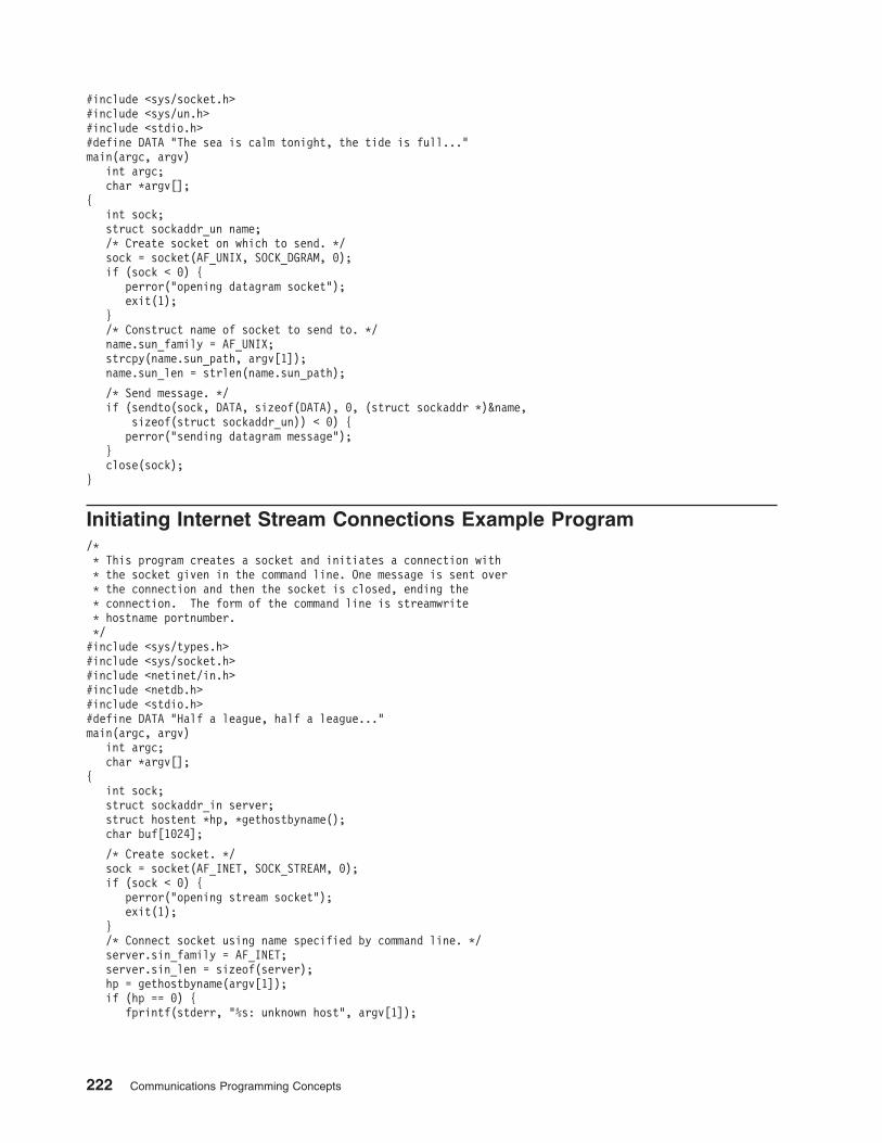
#include <sys/socket.h>
#include <sys/un.h>
#include <stdio.h>
#define DATA "The sea is calm tonight, the tide is full..."
main(argc, argv)
int argc;
char *argv[];
{
int sock;
struct sockaddr_un name;
/* Create socket on which to send. */
sock = socket(AF_UNIX, SOCK_DGRAM, 0);
if (sock < 0) {
perror("opening datagram socket");
exit(1);
}
/* Construct name of socket to send to. */
name.sun_family = AF_UNIX;
strcpy(name.sun_path, argv[1]);
name.sun_len = strlen(name.sun_path);
/* Send message. */
if (sendto(sock, DATA, sizeof(DATA), 0, (struct sockaddr *)&name,
sizeof(struct sockaddr_un)) < 0) {
perror("sending datagram message");
}
close(sock);
}
Initiating Internet Stream Connections Example Program
/*
* This program creates a socket and initiates a connection with
* the socket given in the command line. One message is sent over
* the connection and then the socket is closed, ending the
* connection. The form of the command line is streamwrite
* hostname portnumber.
*/
#include <sys/types.h>
#include <sys/socket.h>
#include <netinet/in.h>
#include <netdb.h>
#include <stdio.h>
#define DATA "Half a league, half a league..."
main(argc, argv)
int argc;
char *argv[];
{
int sock;
struct sockaddr_in server;
struct hostent *hp, *gethostbyname();
char buf[1024];
/* Create socket. */
sock = socket(AF_INET, SOCK_STREAM, 0);
if (sock < 0) {
perror("opening stream socket");
exit(1);
}
/* Connect socket using name specified by command line. */
server.sin_family = AF_INET;
server.sin_len = sizeof(server);
hp = gethostbyname(argv[1]);
if (hp == 0) {
fprintf(stderr, "%s: unknown host", argv[1]);
222 Communications Programming Concepts
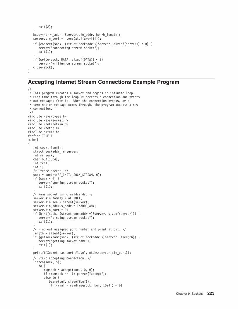
exit(2);
}
bcopy(hp->h_addr, &server.sin_addr, hp->h_length);
server.sin_port = htons(atoi(argv[2]));
if (connect(sock, (struct sockaddr *)&server, sizeof(server)) < 0) {
perror("connecting stream socket");
exit(1);
}
if (write(sock, DATA, sizeof(DATA)) < 0)
perror("writing on stream socket");
close(sock);
}
Accepting Internet Stream Connections Example Program
/*
* This program creates a socket and begins an infinite loop.
* Each time through the loop it accepts a connection and prints
* out messages from it. When the connection breaks, or a
* termination message comes through, the program accepts a new
* connection.
*/
#include <sys/types.h>
#include <sys/socket.h>
#include <netinet/in.h>
#include <netdb.h>
#include <stdio.h>
#define TRUE 1
main()
{
int sock, length;
struct sockaddr_in server;
int msgsock;
char buf[1024];
int rval;
int i;
/* Create socket. */
sock = socket(AF_INET, SOCK_STREAM, 0);
if (sock < 0) {
perror("opening stream socket");
exit(1);
}
/* Name socket using wildcards. */
server.sin_family = AF_INET;
server.sin_len = sizeof(server);
server.sin_addr.s_addr = INADDR_ANY;
server.sin_port = 0;
if (bind(sock, (struct sockaddr *)&server, sizeof(server))) {
perror("binding stream socket");
exit(1);
}
/* Find out assigned port number and print it out. */
length = sizeof(server);
if (getsockname(sock, (struct sockaddr *)&server, &length)) {
perror("getting socket name");
exit(1);
}
printf("Socket has port #%d\n", ntohs(server.sin_port));
/* Start accepting connection. */
listen(sock, 5);
do {
msgsock = accept(sock, 0, 0);
if (msgsock == -1) perror("accept");
else do {
bzero(buf, sizeof(buf));
if ((rval = read(msgsock, buf, 1024)) < 0)
Chapter 9. Sockets 223
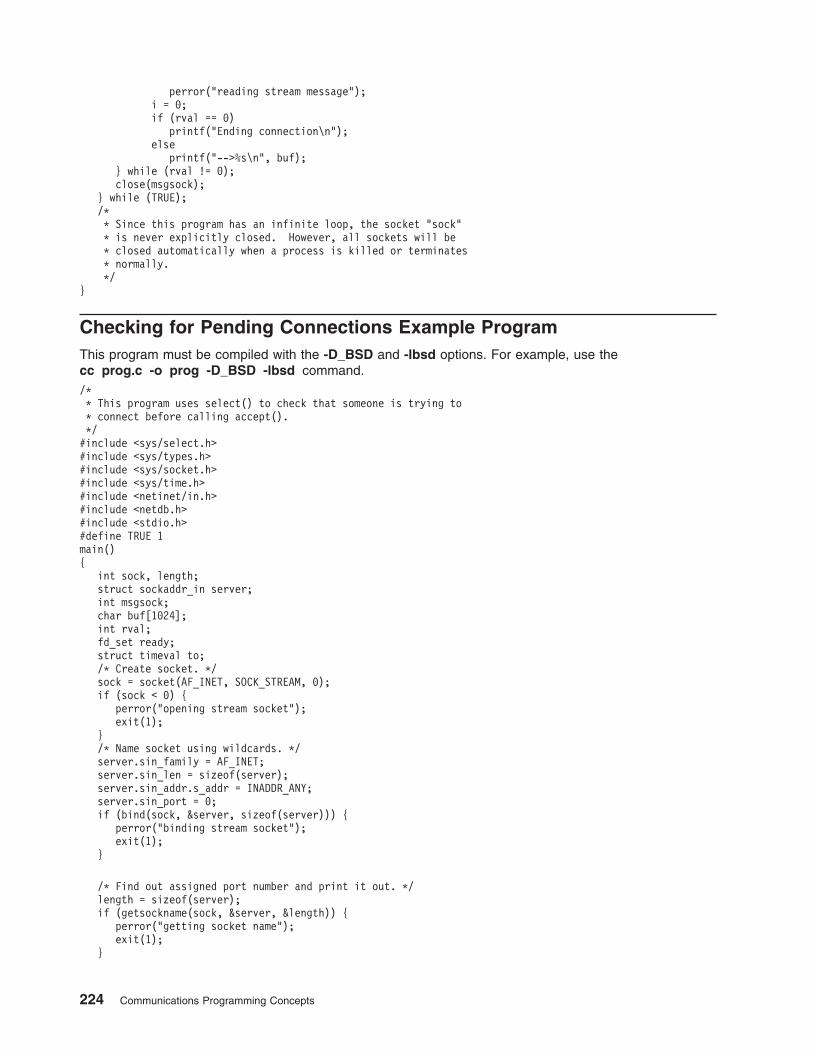
perror("reading stream message");
i = 0;
if (rval == 0)
printf("Ending connection\n");
else
printf("-->%s\n", buf);
} while (rval != 0);
close(msgsock);
} while (TRUE);
/*
* Since this program has an infinite loop, the socket "sock"
* is never explicitly closed. However, all sockets will be
* closed automatically when a process is killed or terminates
* normally.
*/
}
Checking for Pending Connections Example Program
This program must be compiled with the -D_BSD and -lbsd options. For example, use the
cc prog.c -o prog -D_BSD -lbsd command.
/*
* This program uses select() to check that someone is trying to
* connect before calling accept().
*/
#include <sys/select.h>
#include <sys/types.h>
#include <sys/socket.h>
#include <sys/time.h>
#include <netinet/in.h>
#include <netdb.h>
#include <stdio.h>
#define TRUE 1
main()
{
int sock, length;
struct sockaddr_in server;
int msgsock;
char buf[1024];
int rval;
fd_set ready;
struct timeval to;
/* Create socket. */
sock = socket(AF_INET, SOCK_STREAM, 0);
if (sock < 0) {
perror("opening stream socket");
exit(1);
}
/* Name socket using wildcards. */
server.sin_family = AF_INET;
server.sin_len = sizeof(server);
server.sin_addr.s_addr = INADDR_ANY;
server.sin_port = 0;
if (bind(sock, &server, sizeof(server))) {
perror("binding stream socket");
exit(1);
}
/* Find out assigned port number and print it out. */
length = sizeof(server);
if (getsockname(sock, &server, &length)) {
perror("getting socket name");
exit(1);
}
224 Communications Programming Concepts
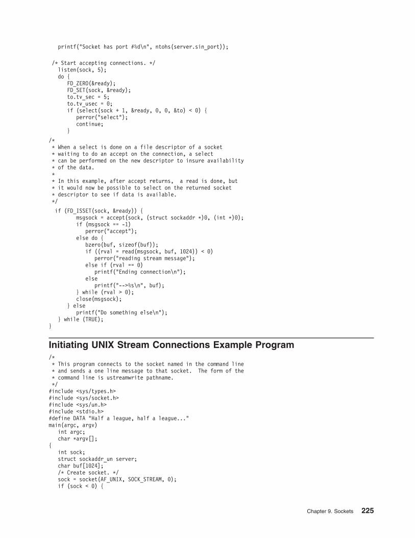
printf("Socket has port #%d\n", ntohs(server.sin_port));
/* Start accepting connections. */
listen(sock, 5);
do {
FD_ZERO(&ready);
FD_SET(sock, &ready);
to.tv_sec = 5;
to.tv_usec = 0;
if (select(sock + 1, &ready, 0, 0, &to) < 0) {
perror("select");
continue;
}
/*
* When a select is done on a file descriptor of a socket
* waiting to do an accept on the connection, a select
* can be performed on the new descriptor to insure availability
* of the data.
*
* In this example, after accept returns, a read is done, but
* it would now be possible to select on the returned socket
* descriptor to see if data is available.
*/
if (FD_ISSET(sock, &ready)) {
msgsock = accept(sock, (struct sockaddr *)0, (int *)0);
if (msgsock == -1)
perror("accept");
else do {
bzero(buf, sizeof(buf));
if ((rval = read(msgsock, buf, 1024)) < 0)
perror("reading stream message");
else if (rval == 0)
printf("Ending connection\n");
else
printf("-->%s\n", buf);
} while (rval > 0);
close(msgsock);
} else
printf("Do something else\n");
} while (TRUE);
}
Initiating UNIX Stream Connections Example Program
/*
* This program connects to the socket named in the command line
* and sends a one line message to that socket. The form of the
* command line is ustreamwrite pathname.
*/
#include <sys/types.h>
#include <sys/socket.h>
#include <sys/un.h>
#include <stdio.h>
#define DATA "Half a league, half a league..."
main(argc, argv)
int argc;
char *argv[];
{
int sock;
struct sockaddr_un server;
char buf[1024];
/* Create socket. */
sock = socket(AF_UNIX, SOCK_STREAM, 0);
if (sock < 0) {
Chapter 9. Sockets 225
perror("opening stream socket");
exit(1);
}
/* Connect socket using name specified by command line. */
server.sun_family = AF_UNIX;
strcpy(server.sun_path, argv[1]);
server.sun_len = strlen(server.sun_path);
if (connect(sock, (struct sockaddr *)&server,
sizeof(struct sockaddr_un)) < 0) {
close(sock);
perror("connecting stream socket");
exit(1);
}
if (write(sock, DATA, sizeof(DATA)) < 0)
perror("writing on stream socket");
}
Accepting UNIX Stream Connections Example Program
/*
* This program creates a socket in the UNIX domain and binds a
* name to it. After printing the socket’s name, a loop begins.
* Each time through the loop it accepts a connection and prints
* out messages from it. When the connection breaks, or a
* termination message comes through, the program accepts a new
* connection.
*/
#include <sys/types.h>
#include <sys/socket.h>
#include <sys/un.h>
#include <stdio.h>
#define NAME "socket"
main()
{
int sock, msgsock, rval;
struct sockaddr_un server;
char buf[1024];
/* Create socket. */
sock = socket(AF_UNIX, SOCK_STREAM, 0);
if (sock < 0) {
perror("opening stream socket");
exit(1);
}
/* Name socket using file system name. */
server.sun_family = AF_UNIX;
strcpy(server.sun_path, NAME);
server.sun_len = strlen(server.sun_path);
if (bind(sock, (struct sockaddr *)&server, SUN_LEN(&server))) {
perror("binding stream socket");
exit(1);
}
printf("Socket has name %s\n", server.sun_path);
/* Start accepting connections. */
listen(sock, 5);
for (;;) {
msgsock = accept(sock, 0, 0); if (msgsock == -1) perror("accept");
else do {
bzero(buf, sizeof(buf));
if ((rval = read(msgsock, buf, 1024)) < 0)
perror("reading stream message");
else if (rval == 0)
printf("Ending connection\n");
else
226 Communications Programming Concepts
printf("-->%s\n", buf);
} while (rval > 0);
close(msgsock);
}
/* The following statements are not executed, because they
* follow an infinite loop. However, most ordinary programs
* will not run forever. In the UNIX domain it is necessary to
* tell the file system that you are through using NAME. In
* most programs you use the call unlink() as below. Since
* the user will have to kill this program, it will be
* necessary to remove the name with a shell command.
*/
close(sock);
unlink(NAME);
}
Sending Data on an ATM Socket PVC Client Example Program
This program must be compiled with the -D_BSD and -lbsd options. For example, use the
cc prog.c -o prog -D_BSD -lbsd command.
/*
*
* ATM Sockets PVC Client Example
*
* This program opens a PVC and sends data on it.
*
*/
#include <stdio.h>
#include <stddef.h>
#include <stdlib.h>
#include <errno.h>
#include <sys/socket.h>
#include <sys/ioctl.h>
#include <sys/ndd_var.h>
#include <sys/atmsock.h>
#define BUFF_SIZE 8192
char buff[BUFF_SIZE];
main(argc, argv)
int argc;
char *argv[];
{
int s; // Socket file descriptor
int error; // Function return code
sockaddr_ndd_atm_t addr; // ATM Socket Address
// Create a socket in the AF_NDD domain of type SOCK_CONN_DGRAM
// and NDD_PROT_ATM protocol.
s = socket(AF_NDD, SOCK_CONN_DGRAM, NDD_PROT_ATM);
if (s == -1) { // Socket either returns the file descriptor
perror("socket"); // or a -1 to indicate an error.
exit(-1);
}
// The bind command associates this socket with a particular
// ATM device, as specified by addr.sndd_atm_nddname.
addr.sndd_atm_len = sizeof(addr);
addr.sndd_atm_family = AF_NDD;
strcpy( addr.sndd_atm_nddname, "atm0" ); // The name of the ATM device
// which is to be used.
error = bind( s, (struct sockaddr *)&addr, sizeof(addr) );
if (error) { // An error from bind would indicate the
perror("bind"); // requested ATM device is not available.
exit(-1); // Check smitty devices.
} /* endif */
Chapter 9. Sockets 227
// To open a PVC, the addr.sndd_atm_vc_type field of the
// sockaddr_ndd_atm is set to CONN_PVC. The VPI and VCI are
// specified in the fields sndd_atm_addr.number.addr[0] and
// sndd_atm_addr.number.addr[1].
addr.sndd_atm_vc_type = CONN_PVC; // Indicates PVC
addr.sndd_atm_addr.number.addr[0] = 0; // VPI
addr.sndd_atm_addr.number.addr[1] = 15; // VCI
error = connect( s, (struct sockaddr *)&addr, sizeof(addr) );
if (error) { // A connect error may indicate that
perror("connect"); // the VPI/VCI is already in use.
exit(-1);
} /* endif */
while (1) {
error = send( s, buff, BUFF_SIZE, 0 );
if (error < 0 ) { // Send returns -1 to
perror("send"); // to indicate an error.
exit(-1); // The errno is set an can
} else { // be displayed with perror.
printf("sent %d bytes\n", error ); // Or it returns the number
} // of bytes transmitted
sleep(1); // Just sleep 1 second, then send more data.
} /* endwhile */
exit(0);
}
Receiving Data on an ATM Socket PVC Server Example Program
This program must be compiled with the -D_BSD and -lbsd options. For example, use the
cc prog.c -o prog -D_BSD -lbsd command.
/*
* ATM Sockets PVC Server Example
*
* This program opens a PVC an receives data on it.
*
*/
#include <stdio.h>
#include <stddef.h>
#include <stdlib.h>
#include <errno.h>
#include <sys/socket.h>
#include <sys/ioctl.h>
#include <sys/ndd_var.h>
#include <sys/atmsock.h>
#define BUFF_SIZE 8192
char buff[BUFF_SIZE];
main(argc, argv)
int argc;
char *argv[];
{
int s; // Socket file descriptor
int error; // Function return code
sockaddr_ndd_atm_t addr; // ATM Socket Address
// Create a socket in the AF_NDD domain of type SOCK_CONN_DGRAM
// and NDD_PROT_ATM protocol.
s = socket(AF_NDD, SOCK_CONN_DGRAM, NDD_PROT_ATM);
if (s == -1) { // Socket either returns the file descriptor
perror("socket"); // or a -1 to indicate an error.
exit(-1);
}
// The bind command associates this socket with a particular
// ATM device, as specified by addr.sndd_atm_nddname.
addr.sndd_atm_len = sizeof(addr);
addr.sndd_atm_family = AF_NDD;
strcpy( addr.sndd_atm_nddname, "atm0" ); // The name of the ATM device
// which is to be used.
228 Communications Programming Concepts
error = bind( s, (struct sockaddr *)&addr, sizeof(addr) );
if (error) { // An error from bind would indicate the
perror("bind"); // requested ATM device is not available.
exit(-1); // Check smitty devices.
} /* endif */
// To open a PVC, the addr.sndd_atm_vc_type field of the
// sockaddr_ndd_atm is set to CONN_PVC. The VPI and VCI are
// specified in the fields sndd_atm_addr.number.addr[0] and
// sndd_atm_addr.number.addr[1].
addr.sndd_atm_vc_type = CONN_PVC; // Indicates PVC
addr.sndd_atm_addr.number.addr[0] = 0; // VPI
addr.sndd_atm_addr.number.addr[1] = 15; // VCI
error = connect( s, (struct sockaddr *)&addr, sizeof(addr) );
if (error) { // A connect error may indicate that
perror("connect"); // the VPI/VCI is already in use.
exit(-1);
} /* endif */
while (1) {
error = recv( s, buff, BUFF_SIZE, 0 );
if (error < 0 ) { // Send returns -1 to
perror("recv"); // to indicate an error.
exit(-1); // The errno is set an can
} else { // be displayed with perror.
printf("received %d bytes\n", error ); // Or it returns the number
} // of bytes received
} /* endwhile */
exit(0);
}
Sending Data on an ATM Socket Rate-Enforced SVC Client Example
Program
This program must be compiled with the -D_BSD and -lbsd options. For example, use the
cc prog.c -o prog -D_BSD -lbsd command.
/*
* ATM Sockets rate enforced SVC Client Example
*
* This program opens a rate enforced (not best effort) SVC
* and sends data on it.
*
*/
#include <stdio.h>
#include <stddef.h>
#include <stdlib.h>
#include <errno.h>
#include <sys/socket.h>
#include <sys/ioctl.h>
#include <sys/ndd_var.h>
#include <sys/atmsock.h>
#define BUFF_SIZE 100000
char buff[BUFF_SIZE];
main(argc, argv)
int argc;
char *argv[];
{
int s; // Socket file descriptor
int error; // Function return code
int i;
sockaddr_ndd_atm_t addr; // ATM Socket Address
unsigned long size; // Size of socket argument
aal_parm_t aal_parm; // AAL parameters
blli_t blli[3]; // Broadband Lower Layer Info
traffic_des_t traffic; // Traffic Descriptor
bearer_t bearer; // Broadband Bearer Capability
int o[20]; // Temporary variable for ATM
Chapter 9. Sockets 229
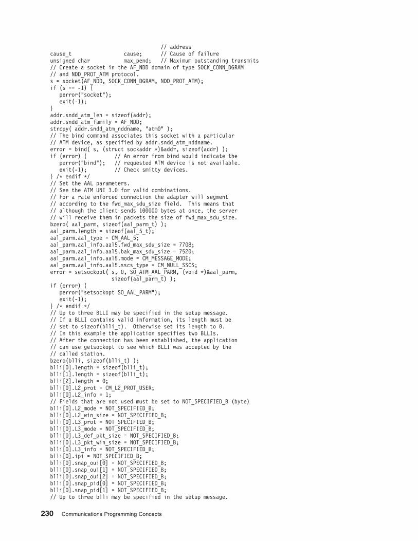
// address
cause_t cause; // Cause of failure
unsigned char max_pend; // Maximum outstanding transmits
// Create a socket in the AF_NDD domain of type SOCK_CONN_DGRAM
// and NDD_PROT_ATM protocol.
s = socket(AF_NDD, SOCK_CONN_DGRAM, NDD_PROT_ATM);
if (s == -1) {
perror("socket");
exit(-1);
}
addr.sndd_atm_len = sizeof(addr);
addr.sndd_atm_family = AF_NDD;
strcpy( addr.sndd_atm_nddname, "atm0" );
// The bind command associates this socket with a particular
// ATM device, as specified by addr.sndd_atm_nddname.
error = bind( s, (struct sockaddr *)&addr, sizeof(addr) );
if (error) { // An error from bind would indicate the
perror("bind"); // requested ATM device is not available.
exit(-1); // Check smitty devices.
} /* endif */
// Set the AAL parameters.
// See the ATM UNI 3.0 for valid combinations.
// For a rate enforced connection the adapter will segment
// according to the fwd_max_sdu_size field. This means that
// although the client sends 100000 bytes at once, the server
// will receive them in packets the size of fwd_max_sdu_size.
bzero( aal_parm, sizeof(aal_parm_t) );
aal_parm.length = sizeof(aal_5_t);
aal_parm.aal_type = CM_AAL_5;
aal_parm.aal_info.aal5.fwd_max_sdu_size = 7708;
aal_parm.aal_info.aal5.bak_max_sdu_size = 7520;
aal_parm.aal_info.aal5.mode = CM_MESSAGE_MODE;
aal_parm.aal_info.aal5.sscs_type = CM_NULL_SSCS;
error = setsockopt( s, 0, SO_ATM_AAL_PARM, (void *)&aal_parm,
sizeof(aal_parm_t) );
if (error) {
perror("setsockopt SO_AAL_PARM");
exit(-1);
} /* endif */
// Up to three BLLI may be specified in the setup message.
// If a BLLI contains valid information, its length must be
// set to sizeof(blli_t). Otherwise set its length to 0.
// In this example the application specifies two BLLIs.
// After the connection has been established, the application
// can use getsockopt to see which BLLI was accepted by the
// called station.
bzero(blli, sizeof(blli_t) );
blli[0].length = sizeof(blli_t);
blli[1].length = sizeof(blli_t);
blli[2].length = 0;
blli[0].L2_prot = CM_L2_PROT_USER;
blli[0].L2_info = 1;
// Fields that are not used must be set to NOT_SPECIFIED_B (byte)
blli[0].L2_mode = NOT_SPECIFIED_B;
blli[0].L2_win_size = NOT_SPECIFIED_B;
blli[0].L3_prot = NOT_SPECIFIED_B;
blli[0].L3_mode = NOT_SPECIFIED_B;
blli[0].L3_def_pkt_size = NOT_SPECIFIED_B;
blli[0].L3_pkt_win_size = NOT_SPECIFIED_B;
blli[0].L3_info = NOT_SPECIFIED_B;
blli[0].ipi = NOT_SPECIFIED_B;
blli[0].snap_oui[0] = NOT_SPECIFIED_B;
blli[0].snap_oui[1] = NOT_SPECIFIED_B;
blli[0].snap_oui[2] = NOT_SPECIFIED_B;
blli[0].snap_pid[0] = NOT_SPECIFIED_B;
blli[0].snap_pid[1] = NOT_SPECIFIED_B;
// Up to three blli may be specified in the setup message.
230 Communications Programming Concepts
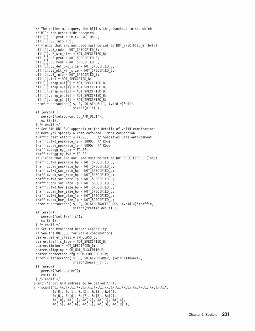
// The caller must query the blli with getsockopt to see which
// blli the other side accepted.
blli[1].L2_prot = CM_L2_PROT_USER;
blli[1].L2_info = 2;
// Fields that are not used must be set to NOT_SPECIFIED_B (byte)
blli[1].L2_mode = NOT_SPECIFIED_B;
blli[1].L2_win_size = NOT_SPECIFIED_B;
blli[1].L3_prot = NOT_SPECIFIED_B;
blli[1].L3_mode = NOT_SPECIFIED_B;
blli[1].L3_def_pkt_size = NOT_SPECIFIED_B;
blli[1].L3_pkt_win_size = NOT_SPECIFIED_B;
blli[1].L3_info = NOT_SPECIFIED_B;
blli[1].ipi = NOT_SPECIFIED_B;
blli[1].snap_oui[0] = NOT_SPECIFIED_B;
blli[1].snap_oui[1] = NOT_SPECIFIED_B;
blli[1].snap_oui[2] = NOT_SPECIFIED_B;
blli[1].snap_pid[0] = NOT_SPECIFIED_B;
blli[1].snap_pid[1] = NOT_SPECIFIED_B;
error = setsockopt( s, 0, SO_ATM_BLLI, (void *)&blli,
sizeof(blli) );
if (error) {
perror("setsockopt SO_ATM_BLLI");
exit(-1);
} /* endif */
// See ATM UNI 3.0 Appendix xx for details of valid combinations
// Here you specify a rate enforced 1 Mbps connection.
traffic.best_effort = FALSE; // Specifies Rate enforcement
traffic.fwd_peakrate_lp = 1000; // Kbps
traffic.bak_peakrate_lp = 1000; // Kbps
traffic.tagging_bak = FALSE;
traffic.tagging_fwd = FALSE;
// Fields that are not used must be set to NOT_SPECIFIED_L (long)
traffic.fwd_peakrate_hp = NOT_SPECIFIED_L;
traffic.bak_peakrate_hp = NOT_SPECIFIED_L;
traffic.fwd_sus_rate_hp = NOT_SPECIFIED_L;
traffic.bak_sus_rate_hp = NOT_SPECIFIED_L;
traffic.fwd_sus_rate_lp = NOT_SPECIFIED_L;
traffic.bak_sus_rate_lp = NOT_SPECIFIED_L;
traffic.fwd_bur_size_hp = NOT_SPECIFIED_L;
traffic.bak_bur_size_hp = NOT_SPECIFIED_L;
traffic.fwd_bur_size_lp = NOT_SPECIFIED_L;
traffic.bak_bur_size_lp = NOT_SPECIFIED_L;
error = setsockopt( s, 0, SO_ATM_TRAFFIC_DES, (void *)&traffic,
sizeof(traffic_des_t) );
if (error) {
perror("set traffic");
exit(-1);
} /* endif */
// Set the Broadband Bearer Capability
// See the UNI 3.0 for valid combinations
bearer.bearer_class = CM_CLASS_C;
bearer.traffic_type = NOT_SPECIFIED_B;
bearer.timing = NOT_SPECIFIED_B;
bearer.clipping = CM_NOT_SUSCEPTIBLE;
bearer.connection_cfg = CM_CON_CFG_PTP;
error = setsockopt( s, 0, SO_ATM_BEARER, (void *)&bearer,
sizeof(bearer_t) );
if (error) {
perror("set bearer");
exit(-1);
} /* endif */
printf("Input ATM address to be called:\n");
i = scanf("%x.%x.%x.%x.%x.%x.%x.%x.%x.%x.%x.%x.%x.%x.%x.%x.%x.%x.%x.%x",
&o[0], &o[1], &o[2], &o[3], &o[4],
&o[5], &o[6], &o[7], &o[8], &o[9],
&o[10], &o[11], &o[12], &o[13], &o[14],
&o[15], &o[16], &o[17], &o[18], &o[19] );
Chapter 9. Sockets 231
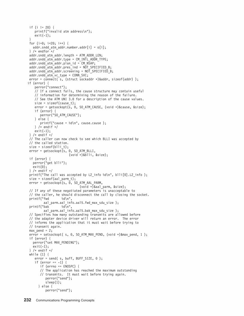
if (i != 20) {
printf("invalid atm address\n");
exit(-1);
}
for (i=0; i<20; i++) {
addr.sndd_atm_addr.number.addr[i] = o[i];
} /* endfor */
addr.sndd_atm_addr.length = ATM_ADDR_LEN;
addr.sndd_atm_addr.type = CM_INTL_ADDR_TYPE;
addr.sndd_atm_addr.plan_id = CM_NSAP;
addr.sndd_atm_addr.pres_ind = NOT_SPECIFIED_B;
addr.sndd_atm_addr.screening = NOT_SPECIFIED_B;
addr.sndd_atm_vc_type = CONN_SVC;
error = connect( s, (struct sockaddr *)&addr, sizeof(addr) );
if (error) {
perror("connect");
// If a connect fails, the cause structure may contain useful
// information for determining the reason of the failure.
// See the ATM UNI 3.0 for a description of the cause values.
size = sizeof(cause_t);
error = getsockopt(s, 0, SO_ATM_CAUSE, (void *)&cause, &size);
if (error) {
perror("SO_ATM_CAUSE");
} else {
printf("cause = %d\n", cause.cause );
} /* endif */
exit(-1);
} /* endif */
// The caller can now check to see which BLLI was accepted by
// the called station.
size = sizeof(blli_t);
error = getsockopt(s, 0, SO_ATM_BLLI,
(void *)&blli, &size);
if (error) {
perror("get blli");
exit(0);
} /* endif */
printf("The call was accepted by L2_info %d\n", blli[0].L2_info );
size = sizeof(aal_parm_t);
error = getsockopt(s, 0, SO_ATM_AAL_PARM,
(void *)&aal_parm, &size);
// If any of these negotiated parameters is unacceptable to
// the caller, he should disconnect the call by closing the socket.
printf("fwd %d\n",
aal_parm.aal_info.aal5.fwd_max_sdu_size );
printf("bak %d\n",
aal_parm.aal_info.aal5.bak_max_sdu_size );
// Specifies how many outstanding transmits are allowed before
// the adapter device driver will return an error. The error
// informs the application that it must wait before trying to
// transmit again.
max_pend = 2;
error = setsockopt( s, 0, SO_ATM_MAX_PEND, (void *)&max_pend, 1 );
if (error) {
perror("set MAX_PENDING");
exit(-1);
} /* endif */
while (1) {
error = send( s, buff, BUFF_SIZE, 0 );
if (error == -1) {
if (errno == ENOSPC) {
// The application has reached the maximum outstanding
// transmits. It must wait before trying again.
perror("send");
sleep(1);
} else {
perror("send");
232 Communications Programming Concepts
size = sizeof(cause_t);
error = getsockopt(s, 0, SO_ATM_CAUSE, (void *)&cause, &size);
if (error) {
perror("SO_ATM_CAUSE");
} else {
printf("cause = %d\n", cause.cause );
}
exit(-1);
} /* endif */
} else {
printf("sent %d\n", error );
}
}
}
Receiving Data on an ATM Socket Rate-Enforced SVC Server Example
Program
This program must be compiled with the -D_BSD and -lbsd options. For example, use the
cc prog.c -o prog -D_BSD -lbsd command.
/*
* ATM Sockets rate enforced SVC Server Example
*
* This program listens for and accepts an SVC and receives data on it.
* It also demostrates AAL negotiation.
*
*/
#include <stdio.h>
#include <stddef.h>
#include <stdlib.h>
#include <errno.h>
#include <sys/socket.h>
#include <sys/ioctl.h>
#include <sys/ndd_var.h>
#include <sys/atmsock.h>
#define BUFF_SIZE 8192
char buff[BUFF_SIZE];
main(argc, argv)
int argc;
char *argv[];
{
int s; // Socket file descriptor
int new_s; // Socket returned by accept
int error; // Function return code
int i;
sockaddr_ndd_atm_t addr; // ATM Socket Address
unsigned long size; // Size of socket argument
aal_parm_t aal_parm; // AAL parameters
blli_t blli[3]; // Broadband Lower Layer Info
traffic_des_t traffic; // Traffic Descriptor
bearer_t bearer; // Broadband Bearer Capability
cause_t cause; // Cause of failure
unsigned char max_pend;
indaccept_ie_t indaccept;
// Create a socket in the AF_NDD domain of type SOCK_CONN_DGRAM
// and NDD_PROT_ATM protocol.
s = socket(AF_NDD, SOCK_CONN_DGRAM, NDD_PROT_ATM);
if (s == -1) {
perror("socket");
exit(-1);
}
addr.sndd_atm_len = sizeof(addr);
addr.sndd_atm_family = AF_NDD;
strcpy( addr.sndd_atm_nddname, "atm0" ); // The name of the ATM device
// which is to be used.
Chapter 9. Sockets 233
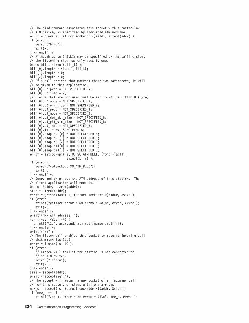
// The bind command associates this socket with a particular
// ATM device, as specified by addr.sndd_atm_nddname.
error = bind( s, (struct sockaddr *)&addr, sizeof(addr) );
if (error) {
perror("bind");
exit(-1);
} /* endif */
// Although up to 3 BLLIs may be specified by the calling side,
// the listening side may only specify one.
bzero(blli, sizeof(blli_t) );
blli[0].length = sizeof(blli_t);
blli[1].length = 0;
blli[2].length = 0;
// If a call arrives that matches these two parameters, it will
// be given to this application.
blli[0].L2_prot = CM_L2_PROT_USER;
blli[0].L2_info = 2;
// Fields that are not used must be set to NOT_SPECIFIED_B (byte)
blli[0].L2_mode = NOT_SPECIFIED_B;
blli[0].L2_win_size = NOT_SPECIFIED_B;
blli[0].L3_prot = NOT_SPECIFIED_B;
blli[0].L3_mode = NOT_SPECIFIED_B;
blli[0].L3_def_pkt_size = NOT_SPECIFIED_B;
blli[0].L3_pkt_win_size = NOT_SPECIFIED_B;
blli[0].L3_info = NOT_SPECIFIED_B;
blli[0].ipi = NOT_SPECIFIED_B;
blli[0].snap_oui[0] = NOT_SPECIFIED_B;
blli[0].snap_oui[1] = NOT_SPECIFIED_B;
blli[0].snap_oui[2] = NOT_SPECIFIED_B;
blli[0].snap_pid[0] = NOT_SPECIFIED_B;
blli[0].snap_pid[1] = NOT_SPECIFIED_B;
error = setsockopt( s, 0, SO_ATM_BLLI, (void *)&blli,
sizeof(blli) );
if (error) {
perror("setsockopt SO_ATM_BLLI");
exit(-1);
} /* endif */
// Query and print out the ATM address of this station. The
// client application will need it.
bzero( &addr, sizeof(addr));
size = sizeof(addr);
error = getsockname( s, (struct sockaddr *)&addr, &size );
if (error) {
printf("getsock error = %d errno = %d\n", error, errno );
exit(-1);
} /* endif */
printf("My ATM address: ");
for (i=0; i<20; i++) {
printf("%X.", addr.sndd_atm_addr.number.addr[i]);
} /* endfor */
printf("\n");
// The listen call enables this socket to receive incoming call
// that match its BLLI.
error = listen( s, 10 );
if (error) {
// Listen will fail if the station is not connected to
// an ATM switch.
perror("listen");
exit(-1);
} /* endif */
size = sizeof(addr);
printf("accepting\n");
// The accept will return a new socket of an incoming call
// for this socket, or sleep until one arrives.
new_s = accept( s, (struct sockaddr *)&addr, &size );
if (new_s == -1) {
printf("accept error = %d errno = %d\n", new_s, errno );
234 Communications Programming Concepts
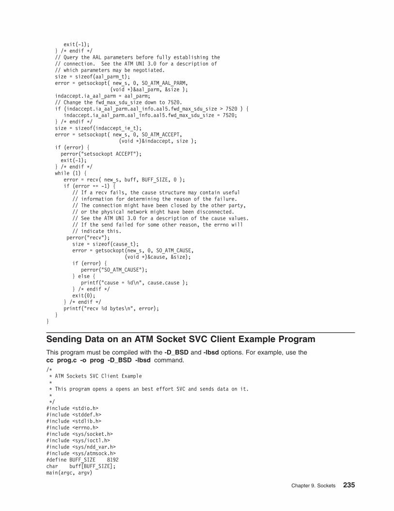
exit(-1);
} /* endif */
// Query the AAL parameters before fully establishing the
// connection. See the ATM UNI 3.0 for a description of
// which parameters may be negotiated.
size = sizeof(aal_parm_t);
error = getsockopt( new_s, 0, SO_ATM_AAL_PARM,
(void *)&aal_parm, &size );
indaccept.ia_aal_parm = aal_parm;
// Change the fwd_max_sdu_size down to 7520.
if (indaccept.ia_aal_parm.aal_info.aal5.fwd_max_sdu_size > 7520 ) {
indaccept.ia_aal_parm.aal_info.aal5.fwd_max_sdu_size = 7520;
} /* endif */
size = sizeof(indaccept_ie_t);
error = setsockopt( new_s, 0, SO_ATM_ACCEPT,
(void *)&indaccept, size );
if (error) {
perror("setsockopt ACCEPT");
exit(-1);
} /* endif */
while (1) {
error = recv( new_s, buff, BUFF_SIZE, 0 );
if (error == -1) {
// If a recv fails, the cause structure may contain useful
// information for determining the reason of the failure.
// The connection might have been closed by the other party,
// or the physical network might have been disconnected.
// See the ATM UNI 3.0 for a description of the cause values.
// If the send failed for some other reason, the errno will
// indicate this.
perror("recv");
size = sizeof(cause_t);
error = getsockopt(new_s, 0, SO_ATM_CAUSE,
(void *)&cause, &size);
if (error) {
perror("SO_ATM_CAUSE");
} else {
printf("cause = %d\n", cause.cause );
} /* endif */
exit(0);
} /* endif */
printf("recv %d bytes\n", error);
}
}
Sending Data on an ATM Socket SVC Client Example Program
This program must be compiled with the -D_BSD and -lbsd options. For example, use the
cc prog.c -o prog -D_BSD -lbsd command.
/*
* ATM Sockets SVC Client Example
*
* This program opens a opens an best effort SVC and sends data on it.
*
*/
#include <stdio.h>
#include <stddef.h>
#include <stdlib.h>
#include <errno.h>
#include <sys/socket.h>
#include <sys/ioctl.h>
#include <sys/ndd_var.h>
#include <sys/atmsock.h>
#define BUFF_SIZE 8192
char buff[BUFF_SIZE];
main(argc, argv)
Chapter 9. Sockets 235
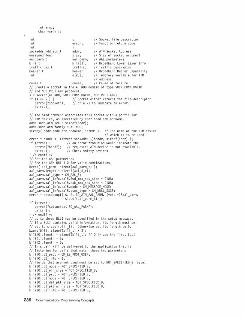
int argc;
char *argv[];
{
int s; // Socket file descriptor
int error; // Function return code
int i;
sockaddr_ndd_atm_t addr; // ATM Socket Address
unsigned long size; // Size of socket argument
aal_parm_t aal_parm; // AAL parameters
blli_t blli[3]; // Broadband Lower Layer Info
traffic_des_t traffic; // Traffic Descriptor
bearer_t bearer; // Broadband Bearer Capability
int o[20]; // Temorary variable for ATM
// address
cause_t cause; // Cause of failure
// Create a socket in the AF_NDD domain of type SOCK_CONN_DGRAM
// and NDD_PROT_ATM protocol.
s = socket(AF_NDD, SOCK_CONN_DGRAM, NDD_PROT_ATM);
if (s == -1) { // Socket either returns the file descriptor
perror("socket"); // or a -1 to indicate an error.
exit(-1);
}
// The bind command associates this socket with a particular
// ATM device, as specified by addr.sndd_atm_nddname.
addr.sndd_atm_len = sizeof(addr);
addr.sndd_atm_family = AF_NDD;
strcpy( addr.sndd_atm_nddname, "atm0" ); // The name of the ATM device
// which is to be used.
error = bind( s, (struct sockaddr *)&addr, sizeof(addr) );
if (error) { // An error from bind would indicate the
perror("bind"); // requested ATM device is not available.
exit(-1); // Check smitty devices.
} /* endif */
// Set the AAL parameters.
// See the ATM UNI 3.0 for valid combinations.
bzero( aal_parm, sizeof(aal_parm_t) );
aal_parm.length = sizeof(aal_5_t);
aal_parm.aal_type = CM_AAL_5;
aal_parm.aal_info.aal5.fwd_max_sdu_size = 9188;
aal_parm.aal_info.aal5.bak_max_sdu_size = 9188;
aal_parm.aal_info.aal5.mode = CM_MESSAGE_MODE;
aal_parm.aal_info.aal5.sscs_type = CM_NULL_SSCS;
error = setsockopt( s, 0, SO_ATM_AAL_PARM, (void *)&aal_parm,
sizeof(aal_parm_t) );
if (error) {
perror("setsockopt SO_AAL_PARM");
exit(-1);
} /* endif */
// Up to three BLLI may be specified in the setup message.
// If a BLLI contains valid information, its length must be
// set to sizeof(blli_t). Otherwise set its length to 0.
bzero(blli, sizeof(blli_t) * 3);
blli[0].length = sizeof(blli_t); // Only use the first BLLI
blli[1].length = 0;
blli[2].length = 0;
// This call will be delivered to the application that is
// listening for calls that match these two parameters.
blli[0].L2_prot = CM_L2_PROT_USER;
blli[0].L2_info = 1;
// Fields that are not used must be set to NOT_SPECIFIED_B (byte)
blli[0].L2_mode = NOT_SPECIFIED_B;
blli[0].L2_win_size = NOT_SPECIFIED_B;
blli[0].L3_prot = NOT_SPECIFIED_B;
blli[0].L3_mode = NOT_SPECIFIED_B;
blli[0].L3_def_pkt_size = NOT_SPECIFIED_B;
blli[0].L3_pkt_win_size = NOT_SPECIFIED_B;
blli[0].L3_info = NOT_SPECIFIED_B;
236 Communications Programming Concepts
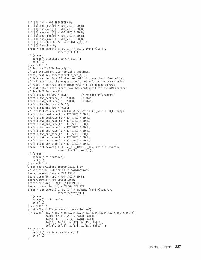
blli[0].ipi = NOT_SPECIFIED_B;
blli[0].snap_oui[0] = NOT_SPECIFIED_B;
blli[0].snap_oui[1] = NOT_SPECIFIED_B;
blli[0].snap_oui[2] = NOT_SPECIFIED_B;
blli[0].snap_pid[0] = NOT_SPECIFIED_B;
blli[0].snap_pid[1] = NOT_SPECIFIED_B;
blli[1].length = 0; /* sizeof(blli_t); */
blli[2].length = 0;
error = setsockopt( s, 0, SO_ATM_BLLI, (void *)&blli,
sizeof(blli) );
if (error) {
perror("setsockopt SO_ATM_BLLI");
exit(-1);
} /* endif */
// Set the Traffic Descriptor
// See the ATM UNI 3.0 for valid settings.
bzero( traffic, sizeof(traffic_des_t) );
// Here we specify a 25 Mbps best effort connection. Best effort
// indicates that the adapter should not enforce the transmission
// rate. Note that the minimum rate will be depend on what
// best effort rate queues have bet configured for the ATM adapter.
// See SMIT for details.
traffic.best_effort = TRUE; // No rate enforcement
traffic.fwd_peakrate_lp = 25000; // Kbps
traffic.bak_peakrate_lp = 25000; // Kbps
traffic.tagging_bak = FALSE;
traffic.tagging_fwd = FALSE;
// Fields that are not used must be set to NOT_SPECIFIED_L (long)
traffic.fwd_peakrate_hp = NOT_SPECIFIED_L;
traffic.bak_peakrate_hp = NOT_SPECIFIED_L;
traffic.fwd_sus_rate_hp = NOT_SPECIFIED_L;
traffic.bak_sus_rate_hp = NOT_SPECIFIED_L;
traffic.fwd_sus_rate_lp = NOT_SPECIFIED_L;
traffic.bak_sus_rate_lp = NOT_SPECIFIED_L;
traffic.fwd_bur_size_hp = NOT_SPECIFIED_L;
traffic.bak_bur_size_hp = NOT_SPECIFIED_L;
traffic.fwd_bur_size_lp = NOT_SPECIFIED_L;
traffic.bak_bur_size_lp = NOT_SPECIFIED_L;
error = setsockopt( s, 0, SO_ATM_TRAFFIC_DES, (void *)&traffic,
sizeof(traffic_des_t) );
if (error) {
perror("set traffic");
exit(-1);
} /* endif */
// Set the Broadband Bearer Capability
// See the UNI 3.0 for valid combinations
bearer.bearer_class = CM_CLASS_C;
bearer.traffic_type = NOT_SPECIFIED_B;
bearer.timing = NOT_SPECIFIED_B;
bearer.clipping = CM_NOT_SUSCEPTIBLE;
bearer.connection_cfg = CM_CON_CFG_PTP;
error = setsockopt( s, 0, SO_ATM_BEARER, (void *)&bearer,
sizeof(bearer_t) );
if (error) {
perror("set bearer");
exit(-1);
} /* endif */
printf("Input ATM address to be called:\n");
i = scanf( "%x.%x.%x.%x.%x.%x.%x.%x.%x.%x.%x.%x.%x.%x.%x.%x.%x.%x.%x.%x",
&o[0], &o[1], &o[2], &o[3], &o[4],
&o[5], &o[6], &o[7], &o[8], &o[9],
&o[10], &o[11], &o[12], &o[13], &o[14],
&o[15], &o[16], &o[17], &o[18], &o[19] );
if (i != 20) {
printf("invalid atm address\n");
exit(-1);
}
Chapter 9. Sockets 237
for (i=0; i<20; i++) {
addr.sndd_atm_addr.number.addr[i] = o[i];
} /* endfor */
addr.sndd_atm_addr.length = ATM_ADDR_LEN;
addr.sndd_atm_addr.type = CM_INTL_ADDR_TYPE;
addr.sndd_atm_addr.plan_id = CM_NSAP;
addr.sndd_atm_addr.pres_ind = NOT_SPECIFIED_B;
addr.sndd_atm_addr.screening = NOT_SPECIFIED_B;
addr.sndd_atm_vc_type = CONN_SVC;
error = connect( s, (struct sockaddr *)&addr, sizeof(addr) );
if (error) {
perror("connect");
// If a connect fails, the cause structure may contain useful
// information for determining the reason of the failure.
// See the ATM UNI 3.0 for a description of the cause values.
size = sizeof(cause_t);
error = getsockopt(s, 0, SO_ATM_CAUSE, (void *)&cause, &size);
if (error) {
perror("SO_ATM_CAUSE");
} else {
printf("cause = %d\n", cause.cause );
} /* endif */
exit(-1);
} /* endif */
while (1) {
error = send( s, buff, BUFF_SIZE, 0 );
if (error == -1) {
// If a send fails, the cause structure may contain useful
// information for determining the reason of the failure.
// The connection might have been closed by the other party,
// or the physical network might have been disconnected.
// See the ATM UNI 3.0 for a description of the cause values.
// If the send failed for some other reason, the errno will
// indicate this.
perror("send");
size = sizeof(cause_t);
error = getsockopt(s, 0, SO_ATM_CAUSE, (void *)&cause, &size);
if (error) {
perror("SO_ATM_CAUSE");
} else {
printf("cause = %d\n", cause.cause );
}
exit(-1);
} else {
printf("sent %d bytes\n", error );
}
sleep(1);
}
}
Receiving Data on an ATM Socket SVC Server Example Program
This program must be compiled with the -D_BSD and -lbsd options. For example, use the
cc prog.c -o prog -D_BSD -lbsd command.
/*
* ATM Sockets SVC Server Example
*
* This program listens for and accepts an SVC and receives data on it.
*
*/
#include <stdio.h>
#include <stddef.h>
#include <stdlib.h>
#include <errno.h>
#include <sys/socket.h>
#include <sys/ioctl.h>
238 Communications Programming Concepts
#include <sys/ndd_var.h>
#include <sys/atmsock.h>
#define BUFF_SIZE 8192
char buff[BUFF_SIZE];
main(argc, argv)
int argc;
char *argv[];
{
int s; // Socket file descriptor
int new_s; // Socket returned by accept
int error; // Function return code
int i;
sockaddr_ndd_atm_t addr; // ATM Socket Address
unsigned long size; // Size of socket argument
aal_parm_t aal_parm; // AAL parameters
blli_t blli[3]; // Broadband Lower Layer Info
traffic_des_t traffic; // Traffic Descriptor
bearer_t bearer; // Broadband Bearer Capability
cause_t cause; // Cause of failure
// Create a socket in the AF_NDD domain of type SOCK_CONN_DGRAM
// and NDD_PROT_ATM protocol.
s = socket(AF_NDD, SOCK_CONN_DGRAM, NDD_PROT_ATM);
if (s == -1) {
perror("socket");
exit(-1);
}
// The bind command associates this socket with a particular
// ATM device, as specified by addr.sndd_atm_nddname.
addr.sndd_atm_len = sizeof(addr);
addr.sndd_atm_family = AF_NDD;
strcpy( addr.sndd_atm_nddname, "atm0" ); // The name of the ATM device
// which is to be used.
error = bind( s, (struct sockaddr *)&addr, sizeof(addr) );
if (error) {
perror("bind");
exit(-1);
} /* endif */
// Although up to 3 BLLIs may be specified by the calling side,
// the listening side may only specify one.
bzero(blli, sizeof(blli_t) );
blli[0].length = sizeof(blli_t);
blli[1].length = 0;
blli[2].length = 0;
// If a call arrives that matches these two parameters, it will
// be given to this application.
blli[0].L2_prot = CM_L2_PROT_USER;
blli[0].L2_info = 1;
// Fields that are not used must be set to NOT_SPECIFIED_B (byte)
blli[0].L2_mode = NOT_SPECIFIED_B;
blli[0].L2_win_size = NOT_SPECIFIED_B;
blli[0].L3_prot = NOT_SPECIFIED_B;
blli[0].L3_mode = NOT_SPECIFIED_B;
blli[0].L3_def_pkt_size = NOT_SPECIFIED_B;
blli[0].L3_pkt_win_size = NOT_SPECIFIED_B;
blli[0].L3_info = NOT_SPECIFIED_B;
blli[0].ipi = NOT_SPECIFIED_B;
blli[0].snap_oui[0] = NOT_SPECIFIED_B;
blli[0].snap_oui[1] = NOT_SPECIFIED_B;
blli[0].snap_oui[2] = NOT_SPECIFIED_B;
blli[0].snap_pid[0] = NOT_SPECIFIED_B;
blli[0].snap_pid[1] = NOT_SPECIFIED_B;
error = setsockopt( s, 0, SO_ATM_BLLI, (void *)&blli,
sizeof(blli) );
if (error) {
perror("setsockopt SO_ATM_BLLI");
exit(-1);
} /* endif */
Chapter 9. Sockets 239
// Query and print out the ATM address of this station. The
// client application will need it.
bzero( &addr, sizeof(addr));
size = sizeof(addr);
error = getsockname( s, (struct sockaddr *)&addr, &size );
if (error) {
perror("getsockname");
exit(-1);
} /* endif */
printf("My ATM address: ");
for (i=0; i<20; i++) {
printf("%X.", addr.sndd_atm_addr.number.addr[i]);
} /* endfor */
printf("\n");
// Although up to 3 BLLIs may be specified by the calling side,
// the listening side may only specify one.
bzero(blli, sizeof(blli_t) );
blli[0].length = sizeof(blli_t);
blli[1].length = 0;
blli[2].length = 0;
// If a call arrives that matches these two parameters, it will
// be given to this application.
blli[0].L2_prot = CM_L2_PROT_USER;
blli[0].L2_info = 1;
// Fields that are not used must be set to NOT_SPECIFIED_B (byte)
blli[0].L2_mode = NOT_SPECIFIED_B;
blli[0].L2_win_size = NOT_SPECIFIED_B;
blli[0].L3_prot = NOT_SPECIFIED_B;
blli[0].L3_mode = NOT_SPECIFIED_B;
blli[0].L3_def_pkt_size = NOT_SPECIFIED_B;
blli[0].L3_pkt_win_size = NOT_SPECIFIED_B;
blli[0].L3_info = NOT_SPECIFIED_B;
blli[0].ipi = NOT_SPECIFIED_B;
blli[0].snap_oui[0] = NOT_SPECIFIED_B;
blli[0].snap_oui[1] = NOT_SPECIFIED_B;
blli[0].snap_oui[2] = NOT_SPECIFIED_B;
blli[0].snap_pid[0] = NOT_SPECIFIED_B;
blli[0].snap_pid[1] = NOT_SPECIFIED_B;
error = setsockopt( s, 0, SO_ATM_BLLI, (void *)&blli,
sizeof(blli) );
if (error) {
perror("setsockopt SO_ATM_BLLI");
exit(-1);
} /* endif */
// Query and print out the ATM address of this station. The
// client application will need it.
bzero( &addr, sizeof(addr));
size = sizeof(addr);
error = getsockname( s, (struct sockaddr *)&addr, &size );
if (error) {
perror("getsockname");
exit(-1);
} /* endif */
bzero( &addr, sizeof(addr));
size = sizeof(addr);
error = getsockname( s, (struct sockaddr *)&addr, &size );
if (error) {
perror("getsockname");
exit(-1);
} /* endif */
// The listen call enables this socket to receive incoming call
// that match its BLLI.
error = listen( s, 10 );
if (error) {
// Listen will fail if the station is not connected to
// an ATM switch.
perror("listen");
240 Communications Programming Concepts
exit(-1);
} /* endif */
size = sizeof(addr);
// The accept will return a new socket of an incoming call
// for this socket, or sleep until one arrives.
new_s = accept( s, (struct sockaddr *)&addr, &size );
if (new_s == -1) {
perror("accept");
exit(-1);
} /* endif */
// In order for the connection to be fully established, the
// SO_ATM_ACCEPT setsockopt call must be issued. An application
// may query the parameters first with getsockopt before deciding
// to fully establish this connection and change some parameters.
// If no parameters are to be changed the third parameter may
// be NULL, otherwise it points to a indaccept_ie structure.
error = setsockopt( new_s, 0, SO_ATM_ACCEPT, NULL, 0 );
if (error) {
perror("setsockopt ACCEPT");
exit(-1);
} /* endif */
while (1) {
error = recv( new_s, buff, BUFF_SIZE, 0 );
if (error == -1) {
// If a recv fails, the cause structure may contain useful
// information for determining the reason of the failure.
// The connection might have been closed by the other party,
// or the physical network might have been disconnected.
// See the ATM UNI 3.0 for a description of the cause values.
// If the send failed for some other reason, the errno will
// indicate this.
perror("recv");
size = sizeof(cause_t);
error = getsockopt(new_s, 0, SO_ATM_CAUSE,
(void *)&cause, &size);
if (error) {
perror("SO_ATM_CAUSE");
} else {
printf("cause = %d\n", cause.cause );
} /* endif */
exit(-1);
} else {
printf("received %d bytes\n", error);
} /* endif */
}
}
Receiving Packets Over Ethernet Example Program
#include <stdio.h>
#include <sys/ndd_var.h>
#include <sys/kinfo.h>
/*
* Get the MAC address of the ethernet adapter we’re using...
*/
getaddr(char *device, char *addr)
{
int size;
struct kinfo_ndd *nddp;
void *end;
int found = 0;
size = getkerninfo(KINFO_NDD, 0, 0, 0);
if (size == 0) {
fprintf(stderr, "No ndds.\n");
exit(0);
}
Chapter 9. Sockets 241
if (size < 0) {
perror("getkerninfo 1");
exit(1);
}
nddp = (struct kinfo_ndd *)malloc(size);
if (!nddp) {
perror("malloc");
exit(1);
}
if (getkerninfo(KINFO_NDD, nddp, &size, 0) < 0) {
perror("getkerninfo 2");
exit(2);
}
end = (void *)nddp + size;
while (((void *)nddp < end) && !found) {
if (!strcmp(nddp->ndd_alias, device) ||
!strcmp(nddp->ndd_name, device)) {
found++;
bcopy(nddp->ndd_addr, addr, 6);
} else
nddp++;
}
return (found);
}
/*
* Hex print function...
*/
pit(str, buf, len)
u_char *str;
u_char *buf;
int len;
{
int i;
printf("%s", str);
for (i=0; i<len; i++)
printf("%2.2X", buf[i]);
printf("\n");
fflush(stdout);
}
/*
* Ethernet packet format...
*/
typedef struct {
unsigned char dst[6];
unsigned char src[6];
unsigned short ethertype;
unsigned char data[1500];
} xmit;
main(int argc, char *argv[]) {
char *device;
u_int ethertype;
xmit buf;
int s;
struct sockaddr_ndd_8022 sa;
int cc;
if (argc != 3) {
printf("Usage: %s <ifname> ethertype\n", argv[0]);
printf("EG: %s ent0 0x600\n", argv[0]);
exit(1);
}
device = argv[1];
sscanf(argv[2], "%x", ðertype);
printf("Ethertype: %x\n", ethertype);
s = socket(AF_NDD, SOCK_DGRAM, NDD_PROT_ETHER);
if (s < 0) {
perror("socket");
242 Communications Programming Concepts
exit(1);
}
sa.sndd_8022_family = AF_NDD;
sa.sndd_8022_len = sizeof(sa);
sa.sndd_8022_filtertype = NS_ETHERTYPE;
sa.sndd_8022_ethertype = (u_short)ethertype;
sa.sndd_8022_filterlen = sizeof(struct ns_8022);
bcopy(device, sa.sndd_8022_nddname, sizeof(sa.sndd_8022_nddname));
if (bind(s, (struct sockaddr *)&sa, sizeof(sa))) {
perror("bind");
exit(2);
}
if (connect(s, (struct sockaddr *)&sa, sizeof(sa)) < 0) {
perror("connect");
exit(3);
}
do {
if ((cc = read(s, &buf, sizeof(buf))) < 0) {
perror("write");
exit(4);
}
if (cc) {
printf("Read %d bytes:\n", cc);
pit("\tsrc = ", buf.src, 6);
pit("\tdst = ", buf.dst, 6);
pit("\ttype = ", &(buf.ethertype), 2);
printf("\tdata string: %s\n", buf.data);
}
} while (cc > 0);
close(s);
}
Sending Packets Over Ethernet Example Program
#include <stdio.h>#include <sys/ndd_var.h>
#include <sys/kinfo.h>
/*
* Get the MAC address of the ethernet adapter we’re using...
*/
getaddr(char *device, char *addr)
{
int size;
struct kinfo_ndd *nddp;
void *end;
int found = 0;
size = getkerninfo(KINFO_NDD, 0, 0, 0);
if (size == 0) {
fprintf(stderr, "No ndds.\n");
exit(0);
}
if (size < 0) {
perror("getkerninfo 1");
exit(1);
}
nddp = (struct kinfo_ndd *)malloc(size);
if (!nddp) {
perror("malloc");
exit(1);
}
if (getkerninfo(KINFO_NDD, nddp, &size, 0) < 0) {
perror("getkerninfo 2");
exit(2);
}
end = (void *)nddp + size;
while (((void *)nddp < end) && !found) {
Chapter 9. Sockets 243
if (!strcmp(nddp->ndd_alias, device) ||
!strcmp(nddp->ndd_name, device)) {
found++;
bcopy(nddp->ndd_addr, addr, 6);
} else
nddp++;
}
return (found);
}
/*
* Hex print function...
*/
pit(str, buf, len)
u_char *str;
u_char *buf;
int len;
{
int i;
printf("%s", str);
for (i=0; i<len; i++)
printf("%2.2X", buf[i]);
printf("\n");
fflush(stdout);
}
/*
* Ethernet packet format...
*/
typedef struct {
unsigned char dst[6];
unsigned char src[6];
unsigned short ethertype;
unsigned char data[1500];
} xmit;
/*
* Convert ascii hardware address into byte string.
*/
hwaddr_aton(a, n)
char *a;
u_char *n;
{
int i, o[6];
i = sscanf(a, "%x:%x:%x:%x:%x:%x", &o[0], &o[1], &o[2],
&o[3], &o[4], &o[5]);
if (i != 6) {
fprintf(stderr, "invalid hardware address ’%s’\n");
return (0);
}
for (i=0; i<6; i++)
n[i] = o[i];
return (6);
}
main(int argc, char *argv[]) {
char srcaddr[6];
char *device, dstaddr[6];
u_int ethertype;
u_int count, size;
xmit buf;
int s;
struct sockaddr_ndd_8022 sa;
int last;
if (argc != 6) {
printf("Usage: %s <ifname> dstaddr ethertype count size\n",
argv[0]);
printf("EG: %s en0 01:02:03:04:05:06 0x600 10 10\n",
argv[0]);
exit(1);
244 Communications Programming Concepts
}
if (!getaddr(argv[1], srcaddr)) {
printf("interface not found\n");
exit(1);
}
device=argv[1];
hwaddr_aton(argv[2], dstaddr);
pit("src addr = ", srcaddr, 6);
pit("dst addr = ", dstaddr, 6);
sscanf(argv[3], "%x", ðertype);
count = atoi(argv[4]);
size = atoi(argv[5]);
if (size > 1500)
size = 1500;
if (size < 60)
size = 60;
printf("Ethertype: %x\n", ethertype);
printf("Count: %d\n", count);
printf("Size: %d\n", size);
s = socket(AF_NDD, SOCK_DGRAM, NDD_PROT_ETHER);
if (s < 0) {
perror("socket");
exit(1);
}
sa.sndd_8022_family = AF_NDD;
sa.sndd_8022_len = sizeof(sa);
sa.sndd_8022_filtertype = NS_ETHERTYPE;
sa.sndd_8022_ethertype = (u_short)ethertype;
sa.sndd_8022_filterlen = sizeof(struct ns_8022);
bcopy(device, sa.sndd_8022_nddname, sizeof(sa.sndd_8022_nddname));
if (bind(s, (struct sockaddr *)&sa, sizeof(sa))) {
perror("bind");
exit(2);
}
bcopy(dstaddr, buf.dst, sizeof(buf.dst));
bcopy(srcaddr, buf.src, sizeof(buf.src));
buf.ethertype = (u_short)ethertype;
if (connect(s, (struct sockaddr *)&sa, sizeof(sa)) < 0) {
perror("connect");
exit(3);
}
last = count;
while (count-- > 0) {
sprintf(buf.data, "Foo%d", last-count);
if (write(s, &buf, size) < 0) {
perror("write");
exit(4);
}
}
close(s);
}
Analyzing Packets Over the Network Example Program
/*
* Simple sniffer to capture 802.2 frames on 802.3 ethernet, token ring,
* FDDI, and other CDLI devices that support 802.2 encapsulation...
*/
#include <stdio.h>
#include <sys/types.h>
#include <sys/ndd_var.h>
#include <sys/tok_demux.h>
#include <netinet/if_802_5.h>
main(argc, argv)
int argc;
Chapter 9. Sockets 245
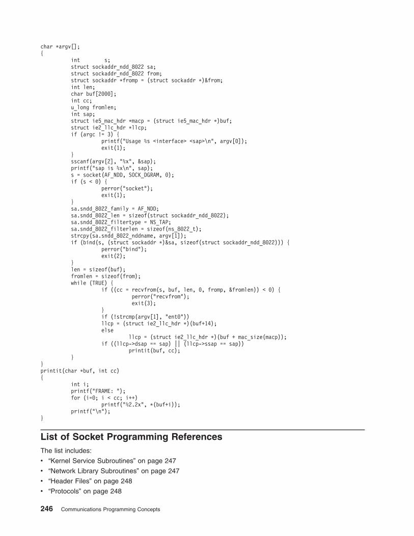
char *argv[];
{
int s;
struct sockaddr_ndd_8022 sa;
struct sockaddr_ndd_8022 from;
struct sockaddr *fromp = (struct sockaddr *)&from;
int len;
char buf[2000];
int cc;
u_long fromlen;
int sap;
struct ie5_mac_hdr *macp = (struct ie5_mac_hdr *)buf;
struct ie2_llc_hdr *llcp;
if (argc != 3) {
printf("Usage %s <interface> <sap>\n", argv[0]);
exit(1);
}
sscanf(argv[2], "%x", &sap);
printf("sap is %x\n", sap);
s = socket(AF_NDD, SOCK_DGRAM, 0);
if (s < 0) {
perror("socket");
exit(1);
}
sa.sndd_8022_family = AF_NDD;
sa.sndd_8022_len = sizeof(struct sockaddr_ndd_8022);
sa.sndd_8022_filtertype = NS_TAP;
sa.sndd_8022_filterlen = sizeof(ns_8022_t);
strcpy(sa.sndd_8022_nddname, argv[1]);
if (bind(s, (struct sockaddr *)&sa, sizeof(struct sockaddr_ndd_8022))) {
perror("bind");
exit(2);
}
len = sizeof(buf);
fromlen = sizeof(from);
while (TRUE) {
if ((cc = recvfrom(s, buf, len, 0, fromp, &fromlen)) < 0) {
perror("recvfrom");
exit(3);
}
if (!strcmp(argv[1], "ent0"))
llcp = (struct ie2_llc_hdr *)(buf+14);
else
llcp = (struct ie2_llc_hdr *)(buf + mac_size(macp));
if ((llcp->dsap == sap) || (llcp->ssap == sap))
printit(buf, cc);
}
}
printit(char *buf, int cc)
{
int i;
printf("FRAME: ");
for (i=0; i < cc; i++)
printf("%2.2x", *(buf+i));
printf("\n");
}
List of Socket Programming References
The list includes:
v “Kernel Service Subroutines” on page 247
v “Network Library Subroutines” on page 247
v “Header Files” on page 248
v “Protocols” on page 248
246 Communications Programming Concepts

Kernel Service Subroutines
accept Accepts a connection on a socket to create a new socket.
bind Binds a name to a socket.
connect Connects two sockets.
getdomainname Gets the name of the current domain.
gethostid Gets the unique identifier of the current host.
gethostname Gets the unique name of the current host.
getpeername Gets the name of the peer socket.
getsockname Gets the socket name.
getsockopt Gets options on sockets.
listen Listens for socket connections and limits the backlog of incoming connections.
recv Receives messages from connected sockets.
recvfrom Receives messages from sockets.
recvmsg Receives a message from any socket.
send Sends messages from a connected socket.
sendmsg Sends a message from a socket by using a message structure.
sendto Sends messages through a socket.
send_file Sends the contents of a file through a socket.
setdomainname Sets the name of the current domain.
sethostid Sets the unique identifier of the current host.
sethostname Sets the unique name of the current host.
setsockopt Sets socket options.
shutdown Shuts down all socket send and receive operations.
socket Creates an end point for communication and returns a descriptor.
socketpair Creates a pair of connected sockets.
Network Library Subroutines
dn_comp Compresses a domain name.
dn_expand Expands a compressed domain name.
endhostent Ends retrieval of network host entries.
endnetent Closes the networks file.
endprotoent Closes the /etc/protocols file.
endservent Closes the /etc/service file entry.
gethostbyaddr Gets network host entry by address.
gethostbyname Gets network host entry by name.
gethostent Gets host entry from the /etc/hosts file.
getnetbyaddr Gets network entry by address.
getnetbyname Gets network entry by name.
getnetent Gets network entry.
getprotobyname Gets protocol entry from the /etc/protocols file by protocol name.
getprotobynumber Gets a protocol entry from the /etc/protocols file by number.
getprotoent Gets protocol entry from the /etc/protocols file.
_getlong Retrieves long byte quantities.
_getshort Retrieves short byte quantities.
getservbyname Gets service entry by name.
getservbyport Gets service entry by port.
getservent Gets services file entry.
htonl Converts an unsigned long integer from host byte order to Internet-network byte
order.
htons Converts an unsigned short integer from host byte order to Internet-network
byte order.
inet_addr Converts Internet addresses to Internet numbers.
Chapter 9. Sockets 247
inet_lnaof Separates local Internet addresses into their network number and local network
address.
inet_makeaddr Makes an Internet address.
inet_netof Separates network Internet addresses into their network number and local
network address.
inet_network Converts Internet network addresses in . (dot) notation to Internet numbers.
inet_ntoa Converts an Internet address into an ASCII string.
ntohl Converts an unsigned long integer from Internet-network standard byte order to
host byte order.
ntohs Converts an unsigned short integer from Internet-network byte order to host
byte order.
_putlong Places long byte quantities into the byte stream.
_putshort Places short byte quantities into the byte stream.
rcmd Allows execution of commands on a remote host.
res_init Searches for a default domain name and Internet address.
res_mkquery Makes query messages for name server.
res_query Provides an interface to the server query mechanism.
res_search Makes a query and awaits a response.
res_send Sends a query to a name server and retrieves a response.
rexec Allows command execution on a remote host.
rresvport Retrieves a socket with a privileged address.
ruserok Allows servers to authenticate clients.
sethostent Opens network host file.
setnetent Opens and rewinds the network file.
setprotoent Opens and rewinds the /etc/protocols file.
setservent. Opens and rewinds the service file.
socks5tcp_connect Connect to a SOCKS version 5 server and request a connection to an external
destination.
socks5tcp_bind Connect to a SOCKS version 5 server and request a listening socket for
incoming remote connections.
socks5tcp_accept Awaits an incoming connection to a socket from a previous socks5tcp_bind call.
socks5udp_associate Connects to a SOCKS version 5 server and requests a UDP association for
subsequent UDP socket communications.
socks5udp_sendto Send UDP packets through a SOCKS version 5 server.
socks5_getserv Returns the address of the SOCKS version 5 server (if any) to use when
connecting to a given destination.
Header Files
/usr/include/netinet/in.h Defines Internet constants and structures.
/usr/include/arpa/nameser.h Contains Internet name-server information.
/usr/include/netdb.h Contains data definitions for socket subroutines.
/usr/include/resolv.h Contains resolver global definitions and variables.
/usr/include/sys/socket.h Contains data definitions and socket structures.
/usr/include/sys/socketvar.h Defines the kernel structure per socket and contains buffer
queues.
/usr/include/sys/types.h Contains data type definitions.
/usr/include/sys/un.h Defines structures for the UNIX Interprocess Communication
domain.
Protocols
PF_UNIX Local communication
PF_INET Internet (TCP/IP)
248 Communications Programming Concepts
Chapter 10. STREAMS
STREAMS is a general, flexible facility and a set of tools for developing system communication services.
With STREAMS, developers can provide services ranging from complete networking protocol suites to
individual device drivers.
This chapter provides an overview of the major STREAMS concepts. Consult UNIX System V Release 4,
Programmer’s Guide: STREAMS and Data Link Provider Interface Specification for additional information.
The following concepts are discussed:
v “STREAMS Introduction”
v “Benefits and Features of STREAMS” on page 252
v “STREAMS Flow Control” on page 254
v “STREAMS Synchronization” on page 255
v “Using STREAMS” on page 262
v “STREAMS Tunable Parameters” on page 263
v “streamio (STREAMS ioctl) Operations” on page 265
v “Building STREAMS” on page 265
v “STREAMS Messages” on page 268
v “Put and Service Procedures” on page 271
v “STREAMS Drivers and Modules” on page 272
v “log Device Driver” on page 275
v “Configuring Drivers and Modules in the Portable Streams Environment” on page 277.
v “An Asynchronous Protocol STREAMS Example” on page 280
v “Differences Between Portable Streams Environment and V.4 STREAMS” on page 285
v “List of STREAMS Programming References” on page 287
v “Transport Service Library Interface Overview” on page 289
STREAMS Introduction
STREAMS represent a collection of system calls, kernel resources, and kernel utility routines that can
create, use, and dismantle a stream. A stream is a full-duplex processing and data transfer path between a
driver in kernel space and a process in user space.
The STREAMS mechanism constructs a stream by serially connecting kernel-resident STREAMS
components, each constructed from a specific set of structures. As shown in the Stream Detail figure
(Figure 32 on page 250), the primary STREAMS components are:
stream head Provides the interface between the stream and user processes. Its principal function is to
process STREAMS-related user system calls. STREAMS system calls can be used from
64-bit and 32-bit user processes.
module Processes data that travels between the stream head and driver. Modules are optional.
stream end Provides the services of an external input/output device or an internal software driver. The
internal software driver is commonly called a pseudo-device driver.
© Copyright IBM Corp. 1994, 2005 249
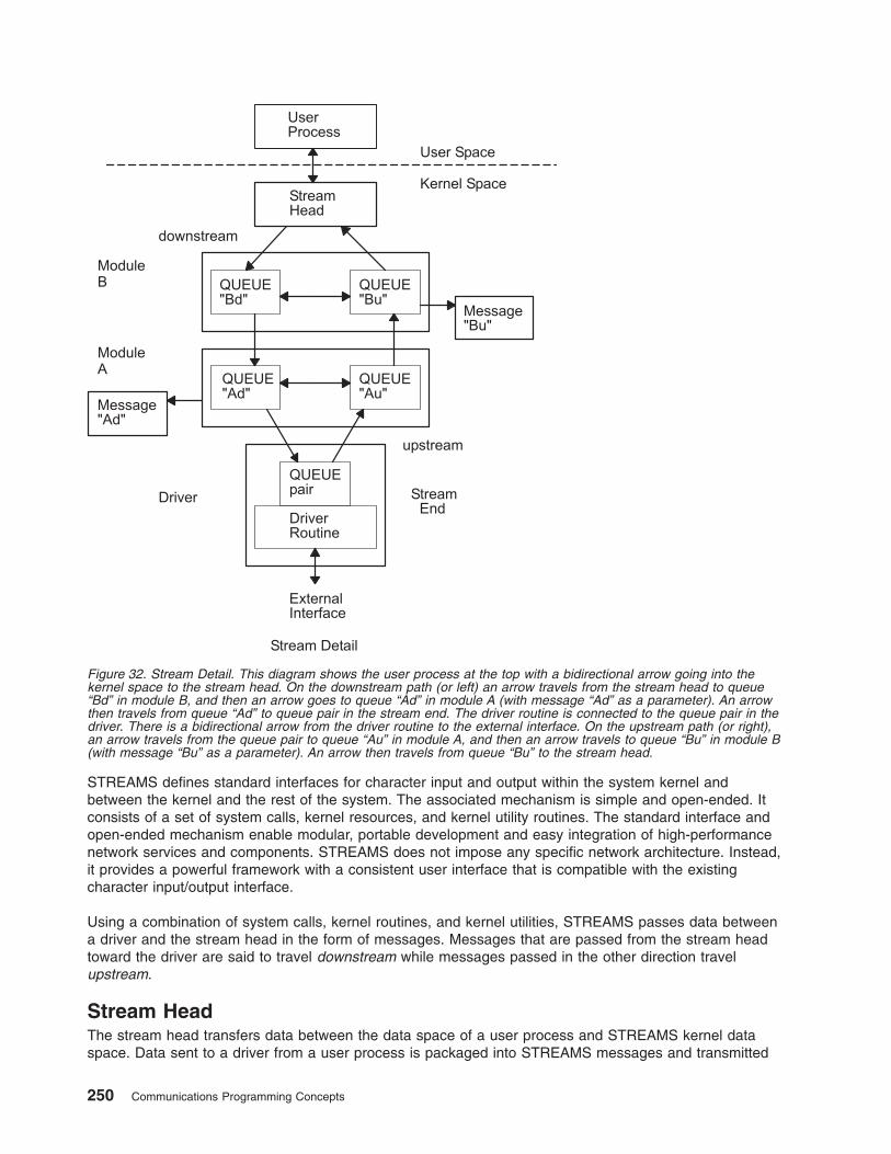
STREAMS defines standard interfaces for character input and output within the system kernel and
between the kernel and the rest of the system. The associated mechanism is simple and open-ended. It
consists of a set of system calls, kernel resources, and kernel utility routines. The standard interface and
open-ended mechanism enable modular, portable development and easy integration of high-performance
network services and components. STREAMS does not impose any specific network architecture. Instead,
it provides a powerful framework with a consistent user interface that is compatible with the existing
character input/output interface.
Using a combination of system calls, kernel routines, and kernel utilities, STREAMS passes data between
a driver and the stream head in the form of messages. Messages that are passed from the stream head
toward the driver are said to travel downstream while messages passed in the other direction travel
upstream.
Stream Head
The stream head transfers data between the data space of a user process and STREAMS kernel data
space. Data sent to a driver from a user process is packaged into STREAMS messages and transmitted
Figure 32. Stream Detail. This diagram shows the user process at the top with a bidirectional arrow going into the
kernel space to the stream head. On the downstream path (or left) an arrow travels from the stream head to queue
“Bd” in module B, and then an arrow goes to queue “Ad” in module A (with message “Ad” as a parameter). An arrow
then travels from queue “Ad” to queue pair in the stream end. The driver routine is connected to the queue pair in the
driver. There is a bidirectional arrow from the driver routine to the external interface. On the upstream path (or right),
an arrow travels from the queue pair to queue “Au” in module A, and then an arrow travels to queue “Bu” in module B
(with message “Bu” as a parameter). An arrow then travels from queue “Bu” to the stream head.
250 Communications Programming Concepts
downstream. Downstream messages arriving at the stream head are processed by the stream head, and
data is copied from user buffers. STREAMS can insert one or more modules into a stream between the
stream head and the driver to process data passing between the two.
The stream head provides an interface between the stream and an application program. The stream head
processes STREAMS-related operations from the application and performs the bidirectional transfer of
data and information between the application (in user space) and messages (in STREAMS kernel space).
Messages are the only means of transferring data and communicating within a stream. A STREAMS
message contains data, status or control information, or a combination of both. Each message includes a
specified message type indicator that identifies the contents.
For more information about the STREAMS message-passing scheme, see “STREAMS Messages” on
page 268.
Modules
A module performs intermediate transformations on messages passing between the stream head and the
driver. Zero or more modules can exist in a stream (zero when the driver performs all the required
character and device processing).
Each module is constructed from a pair of QUEUE structures (see the Au/Ad QUEUE pair and the Bu/Bd
QUEUE pair in the Stream Detail diagram shown previously). A pair of such structures is required to
implement the bidirectional and symmetrical attributes of a stream. One QUEUE (such as the Au or Bu
QUEUE) performs functions on messages passing upstream through the module. The other QUEUE (the
Ad or Bd QUEUE) performs another set of functions on downstream messages. (A QUEUE, which is part
of a module, is different from a message queue, which is described in “STREAMS Flow Control” on page
254.)
Each of the two QUEUEs in a module generally have distinct functions; that is, unrelated processing
procedures and data. The QUEUEs operate independently so that the Au QUEUE does not know if a
message passes though the Ad QUEUE unless the Ad QUEUE is programmed to inform it. Messages and
data can be shared only if the developer specifically programs the module functions to perform the
sharing.
Each QUEUE can directly access the adjacent QUEUE in the direction of message flow (for example, Au
to Bu or stream head to Bd). In addition, within a module, a QUEUE can readily locate its mate and
access its messages (for example, for echoing) and data.
Each QUEUE in a module can contain or point to:
v Messages — These are dynamically attached to the QUEUE on a linked list, or message queue (see
Ad and Bu in the Figure 32 on page 250), as they pass through the module.
v Processing procedures — A put procedure must be incorporated in each QUEUE to process messages.
An optional service procedure for sharing the message processing with the put procedure can also be
incorporated. According to their function, the procedures can send messages upstream or downstream,
and they can also modify the private data in their module.
For more information about processing procedures, see “Put and Service Procedures” on page 271.
v Data — Developers can provide private data if required by the QUEUE to perform message processing
(for example, state information and translation tables).
In general, each of the two QUEUEs in a module has a distinct set of all these elements. Additional
module elements are described later. Although depicted as distinct from modules, a stream head and a
stream end also contain a pair of QUEUEs.
Chapter 10. STREAMS 251
Stream End
A stream end is a module in which the module processing procedures are the driver routines. The
procedures in the stream end are different from those in other modules because they are accessible from
an external device and because the STREAMS mechanism allows multiple streams to be connected to the
same driver.
The driver can be a device driver, providing an interface between kernel space and an external
communications device, or an internal pseudo-device driver. A pseudo-device driver is not directly related
to any external device, and it performs functions internal to the kernel.
Device drivers must transform all data and status or control information between STREAMS message
formats and their external representation. For more information on the differences between STREAMS and
character device drivers, see “STREAMS Drivers and Modules” on page 272.
STREAMS Modularity
STREAMS modularity and design reflect the layers and option characteristics of contemporary networking
architectures. The basic components in a STREAMS implementation are referred to as modules (see
“Modules” on page 273). The modules, which reside in the kernel, offer a set of processing functions and
associated service interfaces. From a user level, modules can be selected dynamically and interconnected
to provide any rational processing sequence. Kernel programming, assembly, and link editing are not
required to create the interconnection. Modules can also be dynamically plugged into existing connections
from user level. STREAMS modularity allows:
v User-level programs that are independent of underlying protocols and physical communication media
v Network architectures and high-level protocols that are independent of underlying protocols, drivers, and
physical communication media
v High-level services that can be created by selecting and connecting low-level services and protocols
v Enhanced portability of protocol modules, resulting from the well-defined structure and interface
standards of STREAMS.
STREAMS Facilities
In addition to modularity, STREAMS provides developers with integral functions, a library of utility routines,
and facilities that expedite software design and implementation. The principal facilities are:
Buffer management Maintains an independent buffer pool for STREAMS.
Scheduling Incorporates a scheduling mechanism for STREAMS.
Asynchronous operation of STREAMS
and user processes
Allows STREAMS-related operations to be performed efficiently from user
level.
Other facilities include flow control (“STREAMS Flow Control” on page 254) to conserve STREAMS
memory and processing resources.
Benefits and Features of STREAMS
STREAMS offers two major benefits for applications programmers:
v Easy creation of modules that offer standard data communications services. See “Creating Service
Interfaces” on page 253.
v The ability to manipulate those modules on a stream. See “Manipulating Modules” on page 253.
Additional STREAMS features are provided to handle characteristic problems of protocol implementation
and to assist in development. There are also kernel- and user-level facilities that support the
implementation of advanced functions and allow asynchronous operation of a user process and STREAMS
input and output. The following features are discussed:
252 Communications Programming Concepts
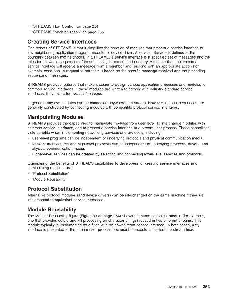
v “STREAMS Flow Control” on page 254
v “STREAMS Synchronization” on page 255
Creating Service Interfaces
One benefit of STREAMS is that it simplifies the creation of modules that present a service interface to
any neighboring application program, module, or device driver. A service interface is defined at the
boundary between two neighbors. In STREAMS, a service interface is a specified set of messages and the
rules for allowable sequences of these messages across the boundary. A module that implements a
service interface will receive a message from a neighbor and respond with an appropriate action (for
example, send back a request to retransmit) based on the specific message received and the preceding
sequence of messages.
STREAMS provides features that make it easier to design various application processes and modules to
common service interfaces. If these modules are written to comply with industry-standard service
interfaces, they are called protocol modules.
In general, any two modules can be connected anywhere in a stream. However, rational sequences are
generally constructed by connecting modules with compatible protocol service interfaces.
Manipulating Modules
STREAMS provides the capabilities to manipulate modules from user level, to interchange modules with
common service interfaces, and to present a service interface to a stream user process. These capabilities
yield benefits when implementing networking services and protocols, including:
v User-level programs can be independent of underlying protocols and physical communication media.
v Network architectures and high-level protocols can be independent of underlying protocols, drivers, and
physical communication media.
v Higher-level services can be created by selecting and connecting lower-level services and protocols.
Examples of the benefits of STREAMS capabilities to developers for creating service interfaces and
manipulating modules are:
v “Protocol Substitution”
v “Module Reusability”
Protocol Substitution
Alternative protocol modules (and device drivers) can be interchanged on the same machine if they are
implemented to equivalent service interfaces.
Module Reusability
The Module Reusability figure (Figure 33 on page 254) shows the same canonical module (for example,
one that provides delete and kill processing on character strings) reused in two different streams. This
module typically is implemented as a filter, with no downstream service interface. In both cases, a tty
interface is presented to the stream user process because the module is nearest the stream head.
Chapter 10. STREAMS 253
STREAMS Flow Control
Even on a well-designed system, general system delays, malfunctions, and excessive accumulation on
one or more streams can cause the message buffer pools to become depleted. Additionally, processing
bursts can arise when a service procedure in one module has a long message queue and processes all its
messages in one pass. STREAMS provides an independent mechanism to guard its message buffer pools
from being depleted and to minimize long processing bursts at any one module.
Note: Flow control is applied only to normal priority messages.
The flow control mechanism is local to each stream and is advisory (voluntary), and it limits the number of
characters that can be queued for processing at any QUEUE in a stream. This mechanism limits the
buffers and related processing at any one QUEUE and in any one stream, but does not consider buffer
pool levels or buffer usage in other streams.
The advisory mechanism operates between the two nearest QUEUEs in a stream containing service
procedures. Messages are generally held on a message queue only if a service procedure is present in
the associated QUEUE.
Messages accumulate at a QUEUE when its service procedure processing does not keep pace with the
message arrival rate, or when the procedure is blocked from placing its messages on the following stream
component by the flow-control mechanism. Pushable modules contain independent upstream and
downstream limits, which are set when a developer specifies high-water and low-water control values for
the QUEUE. The stream head contains a preset upstream limit (which can be modified by a special
message sent from downstream) and a driver may contain a downstream limit.
STREAMS flow control operates in the following order:
Class 1TransportProtocol
SAMEINTERFACE
UserProcess
CanonicalModule
LAPBDriver
Module Reusability Diagram
UserProcess
CanonicalModule
SAMEModule
RawTTYDriver
Figure 33. Module Reusability Diagram. This diagram shows two of the same user processes using the same interface
to communicate with two different streams. The first stream contains the following elements, which are connected with
bidirectional arrows: same interface, canonical module, class 1 transport protocol, and LAPB driver. The second
stream contains the following elements, which are connected with bidirectional arrows: same interface, canonical
module, and raw TTY driver. In each stream, the elements below the a dashed line representing the same interface
are in the same module.
254 Communications Programming Concepts
1. Each time a STREAMS message-handling routine (for example, the putq utility) adds or removes a
message from a message queue in a QUEUE, the limits are checked. STREAMS calculates the total
size of all message blocks on the message queue.
2. The total is compared to the QUEUE high-water and low-water values. If the total exceeds the
high-water value, an internal full indicator is set for the QUEUE. The operation of the service procedure
in this QUEUE is not affected if the indicator is set, and the service procedure continues to be
scheduled (see “Service Procedures” on page 272).
3. The next part of flow control processing occurs in the nearest preceding QUEUE that contains a
service procedure. In the Flow Control diagram (Figure 34), if D is full and C has no service procedure,
then B is the nearest preceding QUEUE.
4. In the Flow Control Diagram, the service procedure in B uses a STREAMS utility routine to see if a
QUEUE ahead is marked full. If messages cannot be sent, the scheduler blocks the service procedure
in B from further execution. B remains blocked until the low-water mark of the full QUEUE D is
reached.
5. While B is blocked (in the Flow Control Diagram), any nonpriority messages that arrive at B will
accumulate on its message queue (recall that priority messages are not blocked). In turn, B can reach
a full state and the full condition will propagate back to the last module in the stream.
6. When the service procedure processing on D (in the Flow Control Diagram) causes the message block
total to fall below the low-water mark, the full indicator is turned off. Then STREAMS automatically
schedules the nearest preceding blocked QUEUE (in this case, B) and gets things moving again. This
automatic scheduling is known as back-enabling a QUEUE.
To use flow control, a developer need only call the utility that tests if a full condition exists ahead (for
example, the canput utility), and perform some housekeeping if it does. Everything else is automatically
handled by STREAMS.
For more information about the STREAMS message-passing scheme, see “STREAMS Messages” on
page 268.
STREAMS Synchronization
In a multi-threaded environment, several threads may access the same stream, the same module, or even
the same queue at the same time. In order to protect the STREAMS resources (queues and other specific
data), STREAMS provides per-thread resource synchronization. This synchronization is ensured by
STREAMS and is completely transparent to the user.
Read the following to learn more about STREAMS synchronization:
v “Synchronization Mechanism” on page 256
v “Synchronization of timeout and bufcall Utilities” on page 256
v “Synchronization Levels” on page 256
Queue B
Queue C
Queue D
MessageQueue
Flow Control Diagram
MessageQueue
Figure 34. Flow Control. This diagram shows queue B, queue C, and queue D side-by-side. Beside each queue is an
arrow coming from the left pointing toward that queue, then another arrow leaving that queue and pointing to the
queue on the right. There are dashed arrows leading down from queue B and queue D to message queues.
Chapter 10. STREAMS 255
v “Per-stream Synchronization” on page 260
v “Queue-Welding Mechanism” on page 261
Synchronization Mechanism
STREAMS uses a synchronization-queueing mechanism that maximizes execution throughput. A
synchronization queue is a linked list of structures. Each structure encapsulates a callback to a function
attempting to access a resource. A thread which cannot block (a service procedure, for example) can
access the resource using a transparent call.
v If the resource is already held by another thread, the thread puts a request on the resource’s
synchronization queue.
v If the resource is free, the thread executes its request immediately. After having done its job, and before
releasing the resource, the thread goes through the synchronization queue and executes all the pending
requests.
In either case, the call returns immediately. Routines performing synchronous operations, like stream head
routines, are blocked until they gain access to the resource. Although the mechanism is completely
transparent, the user needs to set the adequate synchronization level.
Synchronization of timeout and bufcall Utilities
On multiprocessor systems, the timeout and bufcall utilities present a particular problem to the
synchronization mechanism. These utilities specify a callback function. Multiprocessor-safe modules or
drivers require that the callback functions be interrupt-safe.
Multiprocessor-safe modules or drivers are designed to run on any processor. They are very similar to
multiprocessor-safe device drivers. Interrupt-safe functions serialize their code with interrupt handlers.
Functions such as the qenable utility or the wakeup kernel service are interrupt-safe.
To support callback functions that are not interrupt-safe, the STR_QSAFETY flag can be set when calling
the str_install utility. When this flag is set, STREAMS ensures the data integrity of the module. Using this
flag imposes an overhead to the module or driver, thus it should only be used when porting old code.
When writing new code, callback functions must be interrupt-safe.
Synchronization Levels
The STREAMS synchronization mechanism offers flexible selection of synchronization levels. It is possible
to select the set of resources serialized by one synchronization queue.
The synchronization levels are set dynamically by calling the str_install utility when a module or a driver
is loaded. The synchronization levels are implemented by linking synchronization queues together, so that
one synchronization queue is used for several resources. The following synchronization levels are defined:
v “No Synchronization Level”
v “Queue-Level Synchronization” on page 257
v “Queue Pair-Level Synchronization” on page 257
v “Module-Level Synchronization” on page 258
v “Arbitrary-Level Synchronization” on page 259
v “Global-Level Synchronization” on page 260
No Synchronization Level
No synchronization level indicates that each queue can be accessed by more than one thread at the same
time. The protection of internal data and of put and service routines against the timeout or bufcall
utilities is done by the module or driver itself.
This synchronization level is typically used by multiprocessor-efficient modules.
256 Communications Programming Concepts
Queue-Level Synchronization
Queue-level synchronization protects an individual message queue. The module must ensure that no data
inconsistency may occur when two different threads access both upstream and downstream queues at the
same time.
This is the lowest level of synchronization available. It is typically used by modules with no need for
synchronization, either because they share no state or provide their own synchronization or locking.
In the STREAMS Queue-Level Synchronization figure (Figure 35), the queue Bd (downstream queue of
module B) is protected by queue-level synchronization. The bolded box shows the protected area; only
one thread can access this area.
Queue Pair-Level Synchronization
Queue pair-level synchronization protects the pair of message queues (downstream and upstream) of one
instance of a module. The module may share common data between both queues, but it cannot assume
that two instances of the module are accessed by two different threads at the same time.
Queue pair-level synchronization is a common synchronization level for most modules that have only
per-stream data, such as TTY line disciplines. All stream-head queues are synchronized at this level.
In the Queue Pair-Level Synchronization figure (Figure 36 on page 258), the queue pair of module B’s left
instance is protected by queue pair-level synchronization. The boxes highlighted in bold show the
protected area; only one thread can access this area.
Figure 35. STREAMS Queue-Level Synchronization. This diagram shows two streams, with two modules each, where
the first module in each stream is an instance of the same module (Module B). The first stream (on the left) contains
the protected Queue “Bd”, which is downstream in the first instance of Module B.
Chapter 10. STREAMS 257
Module-Level Synchronization
Module-level synchronization protects all instances of one module or driver. The module (or driver) can
have global data, shared among all instances of the module. This data and all message queues are
protected against concurrent access.
Module-level synchronization is the default synchronization level. Modules protected at this level are not
required to be thread-safe, because multiple threads cannot access the module. Module-level
synchronization is also used by modules that maintain shared state information.
In the Module-Level Synchronization figure Figure 37 on page 259), module B (both instances) is protected
by module-level synchronization. The boxes highlighted in bold show the protected area; only one thread
can access this area.
Figure 36. Queue Pair-Level Synchronization. This diagram shows two streams, with two modules each, where the
first module in each stream is an instance of the same module (Module B). The first stream (on the left) contains two
protected queues: Queue “Bd ”which is downstream in the first instance of Module B, and Queue “Bu” which is
upstream in the first instance of Module B.
258 Communications Programming Concepts
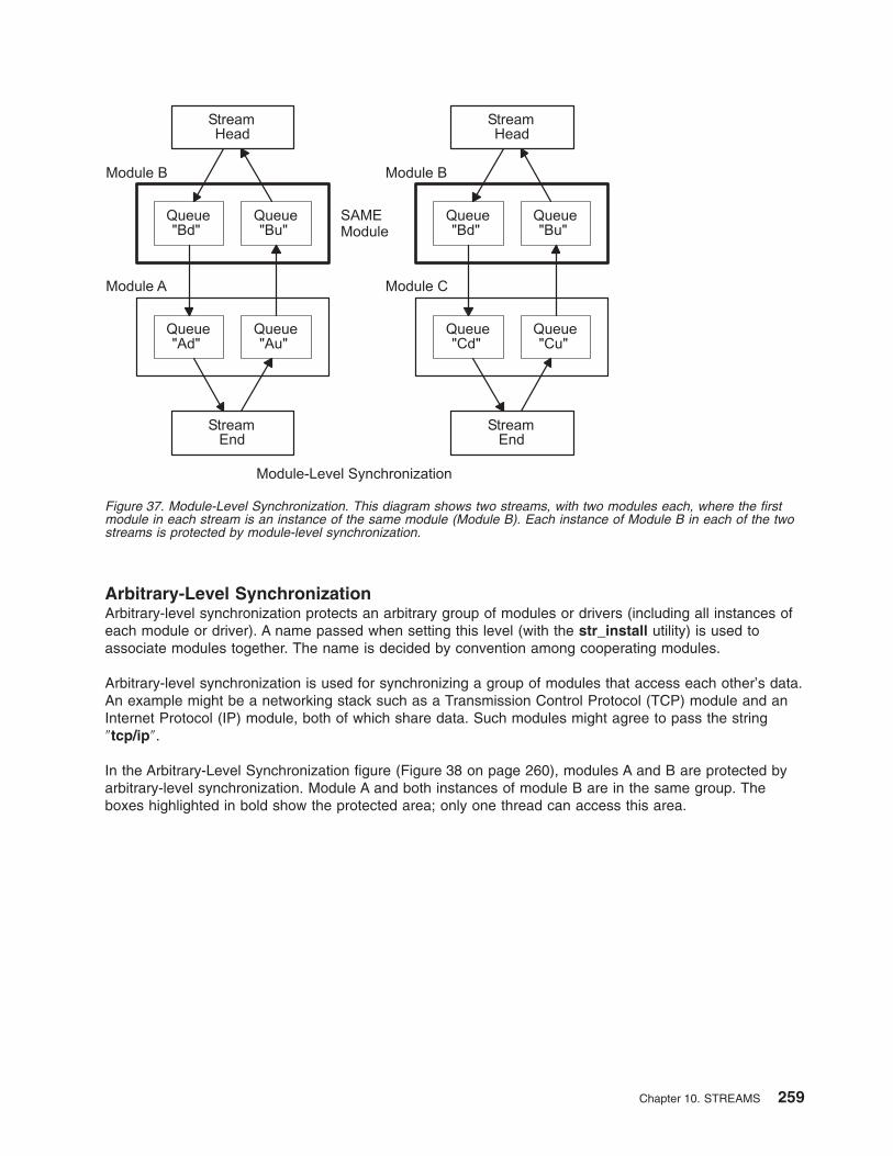
Arbitrary-Level Synchronization
Arbitrary-level synchronization protects an arbitrary group of modules or drivers (including all instances of
each module or driver). A name passed when setting this level (with the str_install utility) is used to
associate modules together. The name is decided by convention among cooperating modules.
Arbitrary-level synchronization is used for synchronizing a group of modules that access each other’s data.
An example might be a networking stack such as a Transmission Control Protocol (TCP) module and an
Internet Protocol (IP) module, both of which share data. Such modules might agree to pass the string
″tcp/ip″.
In the Arbitrary-Level Synchronization figure (Figure 38 on page 260), modules A and B are protected by
arbitrary-level synchronization. Module A and both instances of module B are in the same group. The
boxes highlighted in bold show the protected area; only one thread can access this area.
Figure 37. Module-Level Synchronization. This diagram shows two streams, with two modules each, where the first
module in each stream is an instance of the same module (Module B). Each instance of Module B in each of the two
streams is protected by module-level synchronization.
Chapter 10. STREAMS 259
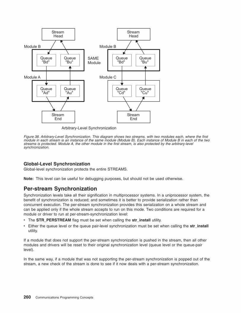
Global-Level Synchronization
Global-level synchronization protects the entire STREAMS.
Note: This level can be useful for debugging purposes, but should not be used otherwise.
Per-stream Synchronization
Synchronization levels take all their signification in multiprocessor systems. In a uniprocessor system, the
benefit of synchronization is reduced; and sometimes it is better to provide serialization rather than
concurrent execution. The per-stream synchronization provides this serialization on a whole stream and
can be applied only if the whole stream accepts to run on this mode. Two conditions are required for a
module or driver to run at per-stream-synchronization level:
v The STR_PERSTREAM flag must be set when calling the str_install utility.
v Either the queue level or the queue pair-level synchronization must be set when calling the str_install
utility.
If a module that does not support the per-stream synchronization is pushed in the stream, then all other
modules and drivers will be reset to their original synchronization level (queue level or the queue-pair
level).
In the same way, if a module that was not supporting the per-stream synchronization is popped out of the
stream, a new check of the stream is done to see if it now deals with a per-stream synchronization.
Figure 38. Arbitrary-Level Synchronization. This diagram shows two streams, with two modules each, where the first
module in each stream is an instance of the same module (Module B). Each instance of Module B in each of the two
streams is protected. Module A, the other module in the first stream, is also protected by the arbitrary-level
synchronization.
260 Communications Programming Concepts
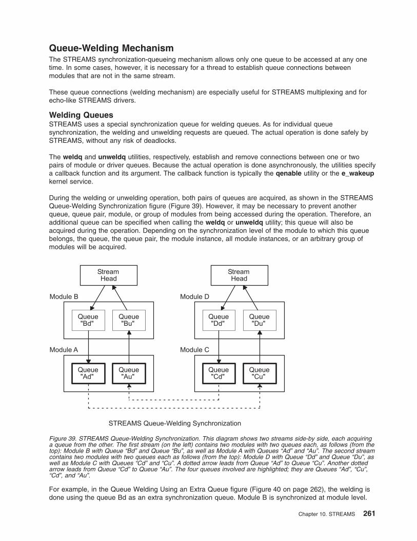
Queue-Welding Mechanism
The STREAMS synchronization-queueing mechanism allows only one queue to be accessed at any one
time. In some cases, however, it is necessary for a thread to establish queue connections between
modules that are not in the same stream.
These queue connections (welding mechanism) are especially useful for STREAMS multiplexing and for
echo-like STREAMS drivers.
Welding Queues
STREAMS uses a special synchronization queue for welding queues. As for individual queue
synchronization, the welding and unwelding requests are queued. The actual operation is done safely by
STREAMS, without any risk of deadlocks.
The weldq and unweldq utilities, respectively, establish and remove connections between one or two
pairs of module or driver queues. Because the actual operation is done asynchronously, the utilities specify
a callback function and its argument. The callback function is typically the qenable utility or the e_wakeup
kernel service.
During the welding or unwelding operation, both pairs of queues are acquired, as shown in the STREAMS
Queue-Welding Synchronization figure (Figure 39). However, it may be necessary to prevent another
queue, queue pair, module, or group of modules from being accessed during the operation. Therefore, an
additional queue can be specified when calling the weldq or unweldq utility; this queue will also be
acquired during the operation. Depending on the synchronization level of the module to which this queue
belongs, the queue, the queue pair, the module instance, all module instances, or an arbitrary group of
modules will be acquired.
For example, in the Queue Welding Using an Extra Queue figure (Figure 40 on page 262), the welding is
done using the queue Bd as an extra synchronization queue. Module B is synchronized at module level.
Figure 39. STREAMS Queue-Welding Synchronization. This diagram shows two streams side-by side, each acquiring
a queue from the other. The first stream (on the left) contains two modules with two queues each, as follows (from the
top): Module B with Queue “Bd” and Queue “Bu”, as well as Module A with Queues “Ad” and “Au”. The second stream
contains two modules with two queues each as follows (from the top): Module D with Queue “Dd” and Queue “Du”, as
well as Module C with Queues “Cd” and “Cu”. A dotted arrow leads from Queue “Ad” to Queue “Cu”. Another dotted
arrow leads from Queue “Cd” to Queue “Au”. The four queues involved are highlighted; they are Queues “Ad”, “Cu”,
“Cd”, and “Au”.
Chapter 10. STREAMS 261
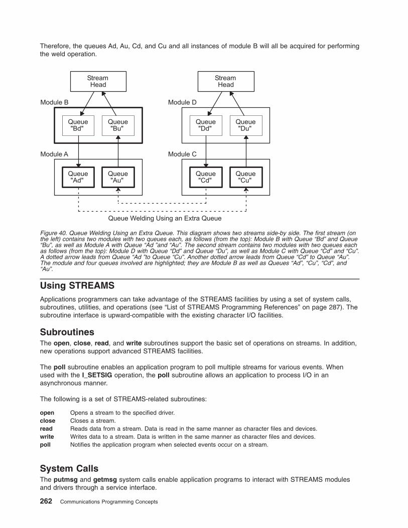
Therefore, the queues Ad, Au, Cd, and Cu and all instances of module B will all be acquired for performing
the weld operation.
Using STREAMS
Applications programmers can take advantage of the STREAMS facilities by using a set of system calls,
subroutines, utilities, and operations (see “List of STREAMS Programming References” on page 287). The
subroutine interface is upward-compatible with the existing character I/O facilities.
Subroutines
The open, close, read, and write subroutines support the basic set of operations on streams. In addition,
new operations support advanced STREAMS facilities.
The poll subroutine enables an application program to poll multiple streams for various events. When
used with the I_SETSIG operation, the poll subroutine allows an application to process I/O in an
asynchronous manner.
The following is a set of STREAMS-related subroutines:
open Opens a stream to the specified driver.
close Closes a stream.
read Reads data from a stream. Data is read in the same manner as character files and devices.
write Writes data to a stream. Data is written in the same manner as character files and devices.
poll Notifies the application program when selected events occur on a stream.
System Calls
The putmsg and getmsg system calls enable application programs to interact with STREAMS modules
and drivers through a service interface.
Figure 40. Queue Welding Using an Extra Queue. This diagram shows two streams side-by side. The first stream (on
the left) contains two modules with two queues each, as follows (from the top): Module B with Queue “Bd” and Queue
“Bu”, as well as Module A with Queue “Ad ”and “Au”. The second stream contains two modules with two queues each
as follows (from the top): Module D with Queue “Dd” and Queue “Du”, as well as Module C with Queue “Cd” and “Cu”.
A dotted arrow leads from Queue “Ad ”to Queue “Cu”. Another dotted arrow leads from Queue “Cd” to Queue “Au”.
The module and four queues involved are highlighted; they are Module B as well as Queues “Ad”, “Cu”, “Cd”, and
“Au”.
262 Communications Programming Concepts
getmsg Receives the message at the stream head.
getpmsg Receives the priority message at the stream head.
putmsg Sends a message downstream.
putpmsg Sends a priority message downstream.
streamio Operations
After a stream has been opened, ioctl operations allow a user process to insert and delete (push and pop)
modules. That process can then communicate with and control the operation of the stream head, modules,
and drivers, and can send and receive messages containing data and control information.
ioctl Controls a stream by enabling application programs to perform functions specific to a particular device. A
set of generic STREAMS ioctl operations (referred to as streamio operations) support a variety of functions
for accessing and controlling streams.
STREAMS Tunable Parameters
Certain system parameters referenced by STREAMS are configurable during system boot or while the
system is running. These parameters are tunable based on requirements. There are two types of
STREAMS tunable parameters: load-time configurable and run-time configurable parameters. At boot time,
the strload command loads the STREAMS framework in the operating system kernel. This command is
used to set both types of parameters using a configuration file. To configure the run-time parameters, use
the no command. The no command also displays all the parameter values. See the no command
description in AIX 5L Version 5.3 Commands Reference for more information.
Load-Time Parameters
The load-time parameters can only be set at initial STREAMS load time. The strload command reads the
parameter names and values from the /etc/pse_tune.conf file. This file can be modified by privileged
users only. It contains parameter names and values in the following format:
# Streams Tunable Parameters
#
# This file contains Streams tunable parameter values.
# The initial values are the same as the default values.
# To change any parameter, modify the parameter value and
# the next system reboot will make it effective.
# To change the run-time parameter, use the no command any time.
strmsgsz 0 # run-time parameter
strctlsz 1024 # run-time parameter
nstrpush 8 # load-time parameter
psetimers 20 # run-time parameter
psebufcalls 20 # run-time parameter
strturncnt 15 # run-time parameter
strthresh 85 # run-time parameter, 85% of "thewall"
lowthresh 90 # tun-time parameter, 90% of "thewall"
medthresh 95 # run-time parameter, 95% of "thewall"
pseintrstack 12288 # load-time parameter, (3 * 4096)
The initial values are the same as the default values. If the user changes any values, they are effective on
the next system reboot. If this file is not present in the system or if it is empty, the strload command will
not fail, and all the parameters are set to their default values.
The load-time parameters are as follows:
nstrpush Indicates the maximum number of modules that can be pushed onto a single STREAM.
The default value is 8.
Chapter 10. STREAMS 263
psetintrstack Indicates the maximum number of the interrupt stack size allowed by STREAMS while
running in the offlevel. Sometimes, when a process, running other than INTBASE level,
enters a STREAM, it encounters stack overflow problems because of not enough interrupt
stack size. Tuning this parameter properly reduces the chances of stack overflow problems.
The default value is 0x3000 (decimal 12288).
Run-Time Parameters
These parameters can be set using the no -o command or the no -d command, and they become
effective immediately. If a user tries to set a load-time parameter to its default value or to a new value
using the no command, it returns an error. The no -a Parameter and no -o Parameter commands show
the parameter’s current value.
The run-time parameters are as follows:
strmsgsz Specifies the maximum number of bytes that a single system call can pass to a STREAM to be
placed into the data part of a message (in M_DATA blocks). Any write subroutine exceeding
this size will be broken into multiple messages. A putmsg subroutine with a data part
exceeding this size will fail returning an ERANGE error code. The default value is 0.
strctlsz Specifies the maximum number of bytes that a single system call can pass to a STREAM to be
placed into the control part of a message (in an M_PROTO or M_PCPROTO block). A putmsg
subroutine with a control part exceeding this size will fail returning an ERANGE error code. The
default value is 1024.
strthresh Specifies the maximum number of bytes STREAMS are allowed to allocate. When the
threshold is passed, users without the appropriate privilege will not be allowed to open
STREAMS, push modules, or write to STREAMS devices. The ENOSR error code is returned.
The threshold applies only to the output side; therefore, data coming into the system is not
affected and continues to work properly. A value of 0 indicates there is no threshold.
The strthresh parameter represents a percentage of the value of the thewall parameter, and its
value can be set between 0 and 100, inclusively. The thewall parameter indicates the maximum
number of bytes that can be allocated by STREAMS and sockets using the net_malloc
subroutine. The user can change the value of the thewall parameter using the no command.
When the user changes the value of the thewall parameter, the threshold gets updated
accordingly. The default value is 85, indicating the threshold is 85% of the value of the thewall
parameter.
psetimers Specifies the maximum number of timers allocated. In the operating system, the STREAM
subsystem allocates a certain number of timer structures at initialization time, so the STREAMS
driver or module can register the timeout requests. Lowering this value is not allowed until the
system reboots, at which time it returns to its default value. The default value is 20.
psebufcalls Specifies the maximum number of bufcalls allocated. In the operating system, the STREAM
subsystem allocates a certain number of bufcall structures at initialization time. When an
allocb subroutine fails, the user can register requests for the bufcall subroutine. Lowering this
value is not allowed until the system reboots, at which time it returns to its default value. The
default value is 20.
strturncnt Specifies the maximum number of requests handled by the currently running thread for module-
or elsewhere-level STREAMS synchronization. The module-level synchronization works in such
a way that only one thread can run in the module at any given time, and all other threads trying
to acquire the same module enqueue their requests and exit. After the currently running thread
completes its work, it dequeues all the previously enqueued requests one at a time and starts
them. If there are large numbers of requests enqueued in the list, the currently running thread
must serve everyone. To eliminate this problem, the currently running thread serves only the
strturncnt number of threads. After that, a separate kernel thread starts all the pending
requests. The default value is 15.
lowthresh Specifies the maximum number of bytes (in percentage) allocated by the thewall parameter
using allocb for the BPRI_LO priority. When the total amount of memory allocated by the
net_malloc subroutine reaches this threshold, the allocb request for the BPRI_LO priority
returns 0. The lowthresh parameter can be set to any value between 0 and 100, inclusively.
The default value is 90, indicating the threshold is at 90% of the value of the thewall parameter.
264 Communications Programming Concepts
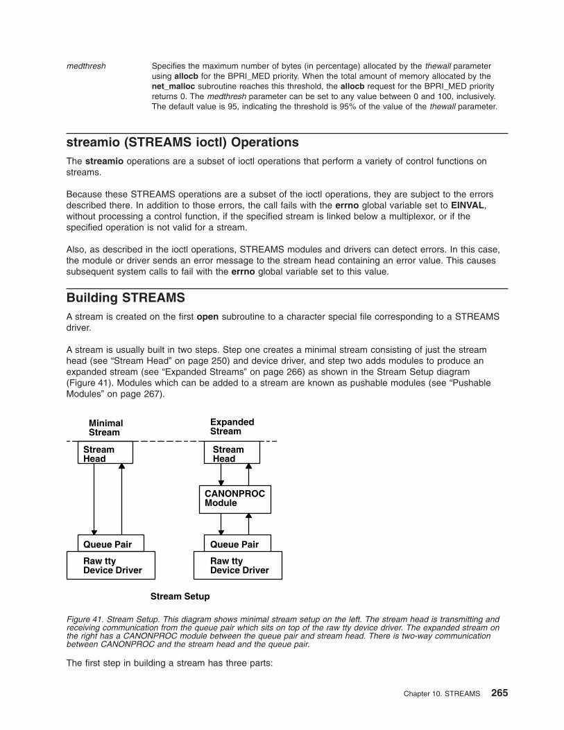
medthresh Specifies the maximum number of bytes (in percentage) allocated by the thewall parameter
using allocb for the BPRI_MED priority. When the total amount of memory allocated by the
net_malloc subroutine reaches this threshold, the allocb request for the BPRI_MED priority
returns 0. The medthresh parameter can be set to any value between 0 and 100, inclusively.
The default value is 95, indicating the threshold is 95% of the value of the thewall parameter.
streamio (STREAMS ioctl) Operations
The streamio operations are a subset of ioctl operations that perform a variety of control functions on
streams.
Because these STREAMS operations are a subset of the ioctl operations, they are subject to the errors
described there. In addition to those errors, the call fails with the errno global variable set to EINVAL,
without processing a control function, if the specified stream is linked below a multiplexor, or if the
specified operation is not valid for a stream.
Also, as described in the ioctl operations, STREAMS modules and drivers can detect errors. In this case,
the module or driver sends an error message to the stream head containing an error value. This causes
subsequent system calls to fail with the errno global variable set to this value.
Building STREAMS
A stream is created on the first open subroutine to a character special file corresponding to a STREAMS
driver.
A stream is usually built in two steps. Step one creates a minimal stream consisting of just the stream
head (see “Stream Head” on page 250) and device driver, and step two adds modules to produce an
expanded stream (see “Expanded Streams” on page 266) as shown in the Stream Setup diagram
(Figure 41). Modules which can be added to a stream are known as pushable modules (see “Pushable
Modules” on page 267).
The first step in building a stream has three parts:
MinimalStream
ExpandedStream
StreamHead
CANONPROCModule
Queue Pair
Raw ttyDevice Driver
Queue Pair
Raw ttyDevice Driver
StreamHead
Stream Setup
Figure 41. Stream Setup. This diagram shows minimal stream setup on the left. The stream head is transmitting and
receiving communication from the queue pair which sits on top of the raw tty device driver. The expanded stream on
the right has a CANONPROC module between the queue pair and stream head. There is two-way communication
between CANONPROC and the stream head and the queue pair.
Chapter 10. STREAMS 265
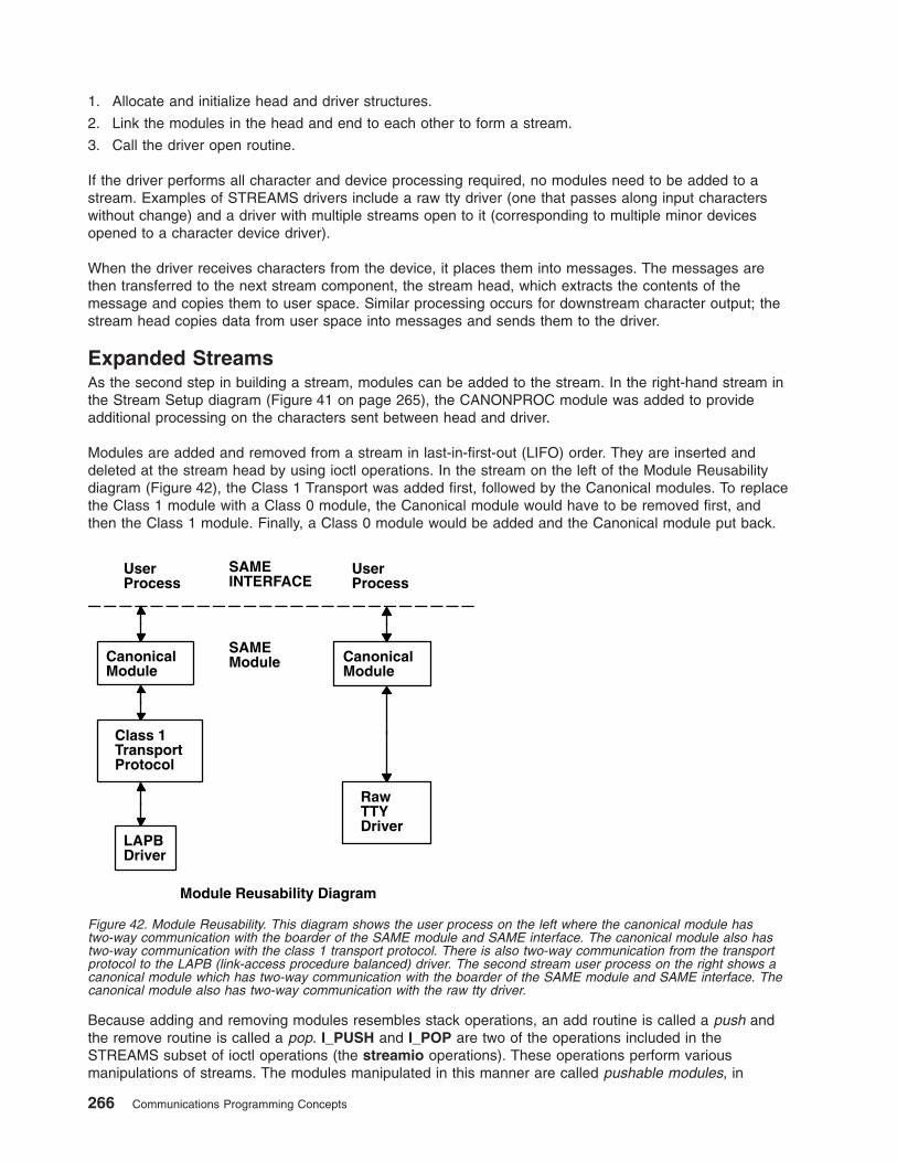
1. Allocate and initialize head and driver structures.
2. Link the modules in the head and end to each other to form a stream.
3. Call the driver open routine.
If the driver performs all character and device processing required, no modules need to be added to a
stream. Examples of STREAMS drivers include a raw tty driver (one that passes along input characters
without change) and a driver with multiple streams open to it (corresponding to multiple minor devices
opened to a character device driver).
When the driver receives characters from the device, it places them into messages. The messages are
then transferred to the next stream component, the stream head, which extracts the contents of the
message and copies them to user space. Similar processing occurs for downstream character output; the
stream head copies data from user space into messages and sends them to the driver.
Expanded Streams
As the second step in building a stream, modules can be added to the stream. In the right-hand stream in
the Stream Setup diagram (Figure 41 on page 265), the CANONPROC module was added to provide
additional processing on the characters sent between head and driver.
Modules are added and removed from a stream in last-in-first-out (LIFO) order. They are inserted and
deleted at the stream head by using ioctl operations. In the stream on the left of the Module Reusability
diagram (Figure 42), the Class 1 Transport was added first, followed by the Canonical modules. To replace
the Class 1 module with a Class 0 module, the Canonical module would have to be removed first, and
then the Class 1 module. Finally, a Class 0 module would be added and the Canonical module put back.
Because adding and removing modules resembles stack operations, an add routine is called a push and
the remove routine is called a pop. I_PUSH and I_POP are two of the operations included in the
STREAMS subset of ioctl operations (the streamio operations). These operations perform various
manipulations of streams. The modules manipulated in this manner are called pushable modules, in
Class 1TransportProtocol
SAMEINTERFACE
UserProcess
CanonicalModule
LAPBDriver
Module Reusability Diagram
UserProcess
CanonicalModule
SAMEModule
RawTTYDriver
Figure 42. Module Reusability. This diagram shows the user process on the left where the canonical module has
two-way communication with the boarder of the SAME module and SAME interface. The canonical module also has
two-way communication with the class 1 transport protocol. There is also two-way communication from the transport
protocol to the LAPB (link-access procedure balanced) driver. The second stream user process on the right shows a
canonical module which has two-way communication with the boarder of the SAME module and SAME interface. The
canonical module also has two-way communication with the raw tty driver.
266 Communications Programming Concepts
contrast to the modules contained in the stream head and stream end. This stack terminology applies only
to the setup, modification, and breakdown of a stream.
Note: Subsequent use of the word module will refer to those pushable modules between stream head and
stream end.
The stream head processes the streamio operation and executes the push, which is analogous to
opening the stream driver. Modules are referenced by a unique symbolic name, contained in the
STREAMS fmodsw module table (similar to the devsw table associated with a device file). The module
table and module name are internal to STREAMS and are accessible from user space only through
STREAMS ioctl subroutines. The fmodsw table points to the module template in the kernel. When a
module is pushed, the template is located, the module structures for both QUEUES are allocated, and the
template values are copied into the structures.
In addition to the module elements, each module contains pointers to an open routine and a close routine.
The open routine is called when the module is pushed, and the close routine is called when the module is
popped. Module open and close procedures are similar to a driver open and close.
As in other files, a STREAMS file is closed when the last process open to it closes the file by the close
subroutine. This subroutine causes the stream to be dismantled (that is, modules are popped and the
driver close routine is executed).
Pushable Modules
Modules are pushed onto a stream to provide special functions and additional protocol layers. In the
Stream Set Up diagram (Figure 41 on page 265), the stream on the left is opened in a minimal
configuration with a raw tty driver and no other module added. The driver receives one character at a time
from the device, places the character in a message, then sends the message upstream. The stream head
receives the message, extracts the single character, then copies it into the reading process buffer to send
to the user process in response to the read subroutine. When the user process wants to send characters
back to the driver, it issues the write subroutine, and the characters are sent to the stream head. The
head copies the characters into one or more multiple-character messages and sends these messages
downstream. An application program requiring no further kernel character processing would use this
minimal stream.
A user requiring a more terminal-like interface would need to insert a module to perform functions such as
echoing, character-erase, and line-kill. Assuming that the CANONPROC module shown in the Stream Set
Up diagram (Figure 41 on page 265) fulfills this need, the application program first opens a raw tty stream.
Then the CANONPROC module is pushed above the driver to create an expanded stream of the form
shown on the right of the diagram. The driver is not aware that a module has been placed above it and
therefore continues to send single character messages upstream. The module receives single-character
messages from the driver, processes the characters, then accumulates them into line strings. Each line is
placed into a message then sent to the stream head. The head now finds more than one character in the
messages it receives from downstream.
Stream head implementation accommodates this change in format automatically and transfers the
multiple-character data into user space. The stream head also keeps track of messages partially
transferred into user space (for example, when the current user read buffer can only hold part of the
current message). Downstream operation is not affected: the head sends, and the driver receives,
multiple-character messages.
The stream head provides the interface between the stream and user process. Modules and drivers do not
have to implement user interface functions other than the open and close subroutines.
Chapter 10. STREAMS 267
STREAMS Messages
STREAMS provides a basic message-passing scheme based on the following concepts:
v “Message Blocks”
v “Message Allocation” on page 269
v “Message Types” on page 269
v “Message Queue Priority” on page 270
v “Sending and Receiving Messages” on page 271
v “Put Procedures” on page 271
v “Service Procedures” on page 272
Message Blocks
A STREAMS message consists of one or more linked message blocks. That is, the first message block of
a message may be attached to other message blocks that are part of the same message. Multiple blocks
in a message can occur, for example, as the result of processing that adds header or trailer data to the
data contained in the message, or because of size limitations in the message buffer that cause the data to
span multiple blocks. When a message is composed of multiple message blocks, the message type of the
first block determines the type of the entire message, regardless of the types of the attached message
blocks.
STREAMS allocates a message as a single block containing a buffer of a certain size. If the data for a
message exceeds the size of the buffer containing the data, the procedure can allocate a new block
containing a larger buffer, copy the current data to it, insert the new data, and deallocate the old block.
Alternatively, the procedure can allocate an additional (smaller) block, place the new data in the new
message block, and link it after or before the initial message block. Both alternatives yield one new
message.
Messages can exist standalone when the message is being processed by a procedure. Alternatively, a
message can await processing on a linked list of messages, called a message queue, in a QUEUE. In the
Message Queue diagram (Figure 43 on page 269), Message 1 is linked to Message 2.
268 Communications Programming Concepts
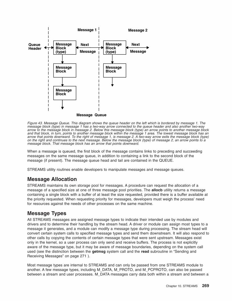
When a message is queued, the first block of the message contains links to preceding and succeeding
messages on the same message queue, in addition to containing a link to the second block of the
message (if present). The message queue head and tail are contained in the QUEUE.
STREAMS utility routines enable developers to manipulate messages and message queues.
Message Allocation
STREAMS maintains its own storage pool for messages. A procedure can request the allocation of a
message of a specified size at one of three message pool priorities. The allocb utility returns a message
containing a single block with a buffer of at least the size requested, provided there is a buffer available at
the priority requested. When requesting priority for messages, developers must weigh the process’ need
for resources against the needs of other processes on the same machine.
Message Types
All STREAMS messages are assigned message types to indicate their intended use by modules and
drivers and to determine their handling by the stream head. A driver or module can assign most types to a
message it generates, and a module can modify a message type during processing. The stream head will
convert certain system calls to specified message types and send them downstream. It will also respond to
other calls by copying the contents of certain message types that were sent upstream. Messages exist
only in the kernel, so a user process can only send and receive buffers. The process is not explicitly
aware of the message type, but it may be aware of message boundaries, depending on the system call
used (see the distinction between the getmsg system call and the read subroutine in “Sending and
Receiving Messages” on page 271 ).
Most message types are internal to STREAMS and can only be passed from one STREAMS module to
another. A few message types, including M_DATA, M_PROTO, and M_PCPROTO, can also be passed
between a stream and user processes. M_DATA messages carry data both within a stream and between a
QueueHeader
MessageBlock(type)
MessageBlock
MessageBlock
Message 1 Message 2
Message
Next MessageBlock(type) Message
Next
MessageBlock
Message Queue
Figure 43. Message Queue. This diagram shows the queue header on the left which is bordered by message 1. The
message block (type) in message 1 has a two-way arrow connected to the queue header and also another two-way
arrow to the message block in message 2. Below this message block (type) an arrow points to another message block
and that block, in turn, points to another message block within the message 1 area. The lowest message block has an
arrow that points downward. To the right of message 1, is message 2. A two-way arrow exits the message block (type)
on the right and continues to the next message. Below the message block (type) of message 2, an arrow points to a
message block. That message block has an arrow that points downward.
Chapter 10. STREAMS 269
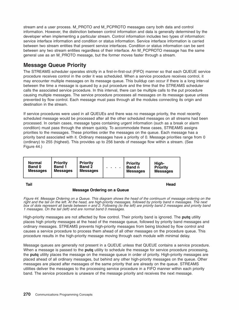
stream and a user process. M_PROTO and M_PCPROTO messages carry both data and control
information. However, the distinction between control information and data is generally determined by the
developer when implementing a particular stream. Control information includes two types of information:
service interface information and condition or status information. Service interface information is carried
between two stream entities that present service interfaces. Condition or status information can be sent
between any two stream entities regardless of their interface. An M_PCPROTO message has the same
general use as an M_PROTO message, but the former moves faster through a stream.
Message Queue Priority
The STREAMS scheduler operates strictly in a first-in-first-out (FIFO) manner so that each QUEUE service
procedure receives control in the order it was scheduled. When a service procedure receives control, it
may encounter multiple messages on its message queue. This buildup can occur if there is a long interval
between the time a message is queued by a put procedure and the time that the STREAMS scheduler
calls the associated service procedure. In this interval, there can be multiple calls to the put procedure
causing multiple messages. The service procedure processes all messages on its message queue unless
prevented by flow control. Each message must pass through all the modules connecting its origin and
destination in the stream.
If service procedures were used in all QUEUEs and there was no message priority, the most recently
scheduled message would be processed after all the other scheduled messages on all streams had been
processed. In certain cases, message types containing urgent information (such as a break or alarm
condition) must pass through the stream quickly. To accommodate these cases, STREAMS assigns
priorities to the messages. These priorities order the messages on the queue. Each message has a
priority band associated with it. Ordinary messages have a priority of 0. Message priorities range from 0
(ordinary) to 255 (highest). This provides up to 256 bands of message flow within a stream. (See
Figure 44.)
High-priority messages are not affected by flow control. Their priority band is ignored. The putq utility
places high priority messages at the head of the message queue, followed by priority band messages and
ordinary messages. STREAMS prevents high-priority messages from being blocked by flow control and
causes a service procedure to process them ahead of all other messages on the procedure queue. This
procedure results in the high-priority message moving through each module with minimal delay.
Message queues are generally not present in a QUEUE unless that QUEUE contains a service procedure.
When a message is passed to the putq utility to schedule the message for service procedure processing,
the putq utility places the message on the message queue in order of priority. High-priority messages are
placed ahead of all ordinary messages, but behind any other high-priority messages on the queue. Other
messages are placed after messages of the same priority that are already on the queue. STREAMS
utilities deliver the messages to the processing service procedure in a FIFO manner within each priority
band. The service procedure is unaware of the message priority and receives the next message.
NormalBand 0Messages
PriorityBand 1Messages
PriorityBand 2Messages
. . . .PriorityBand nMessages
High-PriorityMessages
Tail HeadMessage Ordering on a Queue
Figure 44. Message Ordering on a Queue. This diagram shows the head of the continuum of message ordering on the
right and the tail on the left. At the head, are high-priority messages, followed by priority band n messages. The next
box of dots represent all bands between n and 2. Following (to the left) are priority band 2 messages and priority band
1 messages. On the tail (left) end are normal band 0 messages.
270 Communications Programming Concepts
Message priority is defined by the message type; after a message is created, its priority cannot be
changed. Certain message types come in equivalent high/ordinary priority pairs (for example,
M_PCPROTO and M_PROTO), so that a module or device driver can choose between the two priorities
when sending information.
Sending and Receiving Messages
The putmsg system call is a STREAMS-related system call that sends messages. It is similar to the write
subroutine. The putmsg system call provides a data buffer that is converted into an M_DATA message.
The system call can also provide a separate control buffer to be placed into an M_PROTO or
M_PCPROTO block. The write subroutine provides byte-stream data to be converted into M_DATA
messages.
The getmsg system call is a STREAM-related system call that accepts messages. It is similar to the read
subroutine. One difference between the two calls is that the read subroutine accepts only data (messages
sent upstream to the stream head as message type M_DATA), such as the characters entered from the
terminal. The getmsg system call can simultaneously accept both data and control information (that is, a
message sent upstream as type M_PROTO or M_PCPROTO). The getmsg system call also differs from
the read subroutine in that it preserves message boundaries so that the same boundaries exist above and
below the stream head (that is, between a user process and a stream). The read subroutine generally
ignores message boundaries, processing data as a byte stream.
Certain streamio operations, such as the I_STR operation, also cause messages to be sent or received
on the stream. The I_STR operation provides the general ioctl capability of the character input/output
subsystem. A user process above the stream head can issue the putmsg system call, the getmsg system
call, the I_STR operation, and certain other STREAMS-related functions. Other streamio operations
perform functions that include changing the state of the stream head, pushing and popping modules, or
returning special information.
In addition to message types that explicitly transfer data to a process, some messages sent upstream
result in information transfer. When these messages reach the stream head, they are transformed into
various forms and sent to the user process. The forms include signals, error codes, and call return values.
Put and Service Procedures
The procedures in the QUEUE are the software routines that process messages as they transit the
QUEUE. The processing is generally performed according to the message type and can result in a
modified message, new messages, or no message. A resultant message is generally sent in the same
direction in which it was received by the QUEUE, but may be sent in either direction. A QUEUE always
contains a put procedure and may also contain an associated service procedure.
Put Procedures
A put procedure is the QUEUE routine that receives messages from the preceding QUEUE in the stream.
Messages are passed between QUEUEs by a procedure in one QUEUE calling the put procedure
contained in the following QUEUE. A call to the put procedure in the appropriate direction is generally the
only way to pass messages between modules. (Unless otherwise indicated, the term modules implies a
module, driver, and stream head.) QUEUEs in pushable modules contain a put procedure. In general,
there is a separate put procedure for the read and write QUEUEs in a module because of the full-duplex
operation of most streams.
A put procedure is associated with immediate (as opposed to deferred) processing on a message. Each
module accesses the adjacent put procedure as a subroutine. For example, suppose that modA, modB,
and modC are three consecutive modules in a stream, with modC connected to the stream head. If modA
receives a message to be sent upstream, modA processes that message and then calls the modB put
procedure. The modB procedure processes the message and then calls the modC put procedure. Finally,
the modC procedure processes the message and then calls the stream-head put procedure.
Chapter 10. STREAMS 271
Thus, the message will be passed along the stream in one continuous processing sequence. This
sequence has the benefit of completing the entire processing in a short time with low overhead (subroutine
calls). However, it may not be desirable to use this manner of processing if this sequence is lengthy and
the processing is implemented on a system with multiple users. Using this manner of processing under
those circumstances may be good for this stream but detrimental to other streams since they may have to
wait a long time to be processed.
In addition, some situations exist where the put procedure cannot immediately process the message but
must hold it until processing is allowed. The most typical examples of this are a driver (which must wait
until the current output completes before sending the next message) and the stream head (which may
have to wait until a process initiates the read subroutine on the stream).
Service Procedures
STREAMS allows a service procedure to be contained in each QUEUE, in addition to the put procedure,
to address the above cases and for either purposes. A service procedure is not required in a QUEUE and
is associated with deferred processing. If a QUEUE has both a put and service procedure, message
processing will generally be divided between the procedures. The put procedure is always called first, from
a preceding QUEUE. After the put procedure completes its part of the message processing, it arranges for
the service procedure to be called by passing the message to the putq utility. The putq utility does two
things: it places the message on the message queue of the QUEUE, and it links the QUEUE to the end of
the STREAMS scheduling queue. When the putq utility returns to the put procedure, the procedure
typically exits. Some time later, the service procedure will be automatically called by the STREAMS
scheduler.
The STREAMS scheduler is separate and distinct from the system process scheduler. It is concerned only
with QUEUEs linked on the STREAMS scheduling queue. The scheduler calls the service procedure of the
scheduled QUEUE one at a time, in a FIFO manner.
Having both a put and service procedure in a QUEUE enables STREAMS to provide the rapid response
and the queuing required in systems with many users. The put procedure allows rapid response to certain
data and events, such as software echoing of input characters. Put procedures effectively have higher
priority than any scheduled service procedures. When called from the preceding STREAMS component, a
put procedure starts before the scheduled service procedures of any QUEUE are started.
The service procedure implies message queuing. Queuing results in deferred processing of the service
procedure, following all other QUEUEs currently on the scheduling queue. For example, terminal output,
input erase, and kill processing would typically be performed in a service procedure because this type of
processing does not have to be as timely as echoing. Using a service procedure also allows processing
time to be more evenly spread among multiple streams. As with the put procedure, there will generally be
a separate service procedure for each QUEUE in a module. The flow-control mechanism uses the service
procedures.
STREAMS Drivers and Modules
This section compares operational features of character I/O device drivers with STREAMS drivers and
modules. It is intended for experienced developers of system character device drivers. The Drivers section
includes a discussion of clone device drivers and the log device driver. The Modules section includes a
discussion of the timod and the tirdwr modules. The 64-Bit Support section discusses the impact of 64-bit
support on STREAMS drivers and modules.
Environment
No user environment is generally available to STREAMS module procedures and drivers. Exceptions are
the module and driver open and close routines, both of which have access to the u_area of the calling
process and both of which can sleep. Otherwise, a STREAMS driver, module put procedure, and module
service procedure have no user context and can neither sleep nor access the u_area.
272 Communications Programming Concepts
Multiple streams can use a copy of the same module (that is, the same fmodsw), each containing the
same processing procedures. Therefore, modules must be reentrant, and care must be exercised when
using global data in a module. Put and service procedures are always passed the address of the QUEUE
(for example, in the Stream Detail diagram (Figure 32 on page 250), Au calls the Bu put procedure with Bu
as a parameter). The processing procedure establishes its environment solely from the QUEUE contents,
which is typically the private data (for example, state information).
Drivers
At the interface to hardware devices, character I/O drivers have interrupt entry points; at the system
interface, those same drivers generally have direct entry points (routines) to process open, close, read,
and write subroutines, and ioctl operations.
STREAMS device drivers have similar interrupt entry points at the hardware device interface and have
direct entry points only for the open and close subroutines. These entry points are accessed using
STREAMS, and the call formats differ from character device drivers. The put procedure is a driver’s third
entry point, but it is a message (not system) interface. The stream head translates write subroutines and
ioctl operations into messages and sends them downstream to be processed by the driver’s write QUEUE
put procedure. The read subroutine is seen directly only by the stream head, which contains the functions
required to process subroutines. A driver does not know about system interfaces other than the open and
close subroutines, but it can detect the absence of a read subroutine indirectly if flow control propagates
from the stream head to the driver and affects the driver’s ability to send messages upstream.
For input processing, when the driver is ready to send data or other information to a user process, it does
not wake up the process. It prepares a message and sends it to the read QUEUE of the appropriate
(minor device) stream. The driver’s open routine generally stores the QUEUE address corresponding to
this stream.
For output processing, the driver receives messages from the stream head instead of processing a write
subroutine. If a message cannot be sent immediately to the hardware, it may be stored on the driver’s
write message queue. Subsequent output interrupts can remove messages from this queue.
Drivers and modules can pass signals, error codes, and return values to processes by using message
types provided for that purpose.
There are three special device drivers:
clone Finds and opens an unused minor device on another STREAMS driver.
log Provides an interface for the STREAMS error-logging and event-tracing processes.
sad Provides an interface for administrative operations.
Modules
Modules have user context available only during the execution of their open and close routines. Otherwise,
the QUEUEs forming the module are not associated with the user process at the end of the stream, nor
with any other process. Because of this, QUEUE procedures must not sleep when they cannot proceed;
instead, they must explicitly return control to the system. The system saves no state information for the
QUEUE. The QUEUE must store this information internally if it is to proceed from the same point on a
later entry.
When a module or driver that requires private working storage (for example, for state information) is
pushed, the open routine must obtain the storage from external sources. STREAMS copies the module
template from the fmodsw table for the I_PUSH operation, so only fixed data can be contained in the
module template. STREAMS has no automatic mechanism to allocate working storage to a module when it
is opened. The sources for the storage typically include either a module-specific kernel array, installed
when the system is configured, or the STREAMS buffer pool. When using an array as a module storage
Chapter 10. STREAMS 273
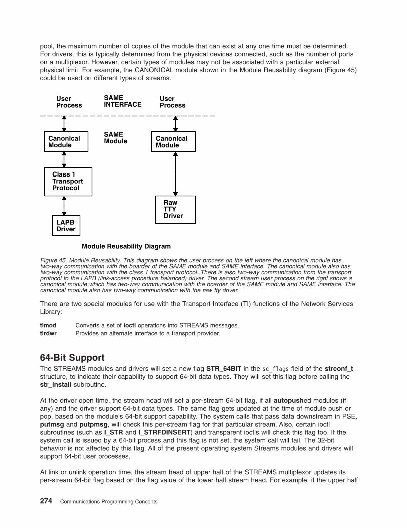
pool, the maximum number of copies of the module that can exist at any one time must be determined.
For drivers, this is typically determined from the physical devices connected, such as the number of ports
on a multiplexor. However, certain types of modules may not be associated with a particular external
physical limit. For example, the CANONICAL module shown in the Module Reusability diagram (Figure 45)
could be used on different types of streams.
There are two special modules for use with the Transport Interface (TI) functions of the Network Services
Library:
timod Converts a set of ioctl operations into STREAMS messages.
tirdwr Provides an alternate interface to a transport provider.
64-Bit Support
The STREAMS modules and drivers will set a new flag STR_64BIT in the sc_flags field of the strconf_t
structure, to indicate their capability to support 64-bit data types. They will set this flag before calling the
str_install subroutine.
At the driver open time, the stream head will set a per-stream 64-bit flag, if all autopushed modules (if
any) and the driver support 64-bit data types. The same flag gets updated at the time of module push or
pop, based on the module’s 64-bit support capability. The system calls that pass data downstream in PSE,
putmsg and putpmsg, will check this per-stream flag for that particular stream. Also, certain ioctl
subroutines (such as I_STR and I_STRFDINSERT) and transparent ioctls will check this flag too. If the
system call is issued by a 64-bit process and this flag is not set, the system call will fail. The 32-bit
behavior is not affected by this flag. All of the present operating system Streams modules and drivers will
support 64-bit user processes.
At link or unlink operation time, the stream head of upper half of the STREAMS multiplexor updates its
per-stream 64-bit flag based on the flag value of the lower half stream head. For example, if the upper half
Class 1TransportProtocol
SAMEINTERFACE
UserProcess
CanonicalModule
LAPBDriver
Module Reusability Diagram
UserProcess
CanonicalModule
SAMEModule
RawTTYDriver
Figure 45. Module Reusability. This diagram shows the user process on the left where the canonical module has
two-way communication with the boarder of the SAME module and SAME interface. The canonical module also has
two-way communication with the class 1 transport protocol. There is also two-way communication from the transport
protocol to the LAPB (link-access procedure balanced) driver. The second stream user process on the right shows a
canonical module which has two-way communication with the boarder of the SAME module and SAME interface. The
canonical module also has two-way communication with the raw tty driver.
274 Communications Programming Concepts
supports 64-bit and lower half does not, then the multiplexor will not support 64-bit processes. This is
necessary because all the system calls are processed at the upper half of the multiplexor.
STREAMS Message Block MSG64BIT Flag
The STREAMS modules and drivers establish the 64-bit or 32-bit user process context by setting the
message block flag (the b_flag field of msgb structure), MSG64BIT. This flag is set by the streams head
when it allocates a message to process a system call from a 64-bit process. This flag is set for the
putmsg, putpmsg, and ioctl system calls; for the I_STR and I_STRFDINSERT commands; and for
transparent ioctls.
Transparent ioctls
The third argument of the transparent ioctl is a pointer to the data in user space to be copied in or out.
This address is remapped properly by the ioctl system call. The streams driver or module passes
M_COPYIN or M_COPYOUT messages to the stream head and the stream head calls the copyin or
copyout subroutines.
If the third argument of the ioctl subroutine points to a structure that contains a pointer (for example,
ptr64) or long, remapping is solved by a new structure, copyreq64, which contains a 64-bit user space
pointer. If the message block flag is set to MSG64BIT, the driver or module will pass M_COPYIN64 or
M_COPYOUT64 to copy in or out a pointer within a structure. In this case, the stream head will call
copyin64 or copyout64 to move the data into or out of the user address space, respectively.
The copyreq64 structure uses the last unused cq_filler field to store the 64-bit address. The copyreq64
structure looks like the following example:
struct copyreq64 {
int cq_cmd; /* command type == ioc_cmd */
cred_t *cq_cr; /* pointer to full credentials*/
int cq_id; /* ioctl id == ioc_id */
ioc_pad cq_ad; /* addr to copy data to/from */
uint cq_size; /* number of bytes to copy */
int cq_flag; /* reserved */
mblk_t *cq_private; /* module’s private state info*/
ptr64 cq_addr64; /* 64-bit address */
long cq_filler[2]; /* reserved */
};
The cq_addr64 field is added in the above structure and the size of the cq_filler is reduced, so overall
size remains same. The driver or module first determines whether the MSG64BIT flag is set and, if so,
stores the user-space 64-bit address in the cq_addr64 field.
log Device Driver
The log driver is a STREAMS software device driver that provides an interface for the STREAMS
error-logging and event-tracing processes. The log driver presents two separate interfaces:
v A function call interface in the kernel through which STREAMS drivers and modules submit log
messages
v A subset of ioctl operations and STREAMS messages for interaction with a user-level error logger, a
trace logger, or processes that need to submit their own log messages
Kernel Interface
The log messages are generated within the kernel by calls to the strlog utility.
User Interface
The log driver is opened using the clone interface, /dev/slog. Each open of /dev/slog obtains a separate
stream to log. In order to receive log messages, a process must first notify the log driver whether it is an
error logger or trace logger by using an I_STR operation.
Chapter 10. STREAMS 275

For the error logger, the I_STR operation has an ic_cmd parameter value of I_ERRLOG with no
accompanying data.
For the trace logger, the I_STR operation has an ic_cmd parameter value of I_TRCLOG, and must be
accompanied by a data buffer containing an array of one or more trace_ids structures. Each trace_ids
structure specifies a mid, sid, and level field from which messages are accepted. The strlog subroutine
accepts messages whose values in the mid and sid fields exactly match those in the trace_ids structure,
and whose level is less than or equal to the level given in the trace_ids structure. A value of -1 in any of
the fields of the trace_ids structure indicates that any value is accepted for that field.
At most, one trace logger and one error logger can be active at a time. After the logger process has
identified itself by using the ioctl operation, the log driver will begin sending messages, subject to the
restrictions previously noted. These messages are obtained by using the getmsg system call. The control
part of this message contains a log_ctl structure, which specifies the mid, sid, level, and flags fields, as
well as the time in ticks since boot that the message was submitted, the corresponding time in seconds
since Jan. 1, 1970, and a sequence number. The time in seconds since 1970 is provided so that the date
and time of the message can be easily computed; the time in ticks since boot is provided so that the
relative timing of log messages can be determined.
Different sequence numbers are maintained for the error-logging and trace-logging streams so that gaps in
the sequence of messages can be determined. (During times of high message traffic, some messages
may not be delivered by the logger to avoid tying up system resources.) The data part of the message
contains the unexpanded text of the format string (null-terminated), followed by the arguments to the
format string (up to the number specified by the NLOGARGS value), aligned on the first word boundary
following the format string.
A process may also send a message of the same structure to the log driver, even if it is not an error or
trace logger. The only fields of the log_ctl structure in the control part of the message that are accepted
are the level and flags fields. All other fields are filled in by the log driver before being forwarded to the
appropriate logger. The data portion must contain a null-terminated format string, and any arguments (up
to NLOGARGS) must be packed one word each, on the next word boundary following the end of the
format string.
Attempting to issue an I_TRCLOG or I_ERRLOG operation when a logging process of the given type
already exists results in the ENXIO error being returned. Similarly, ENXIO is returned for I_TRCLOG
operations without any trace_ids structures, or for any unrecognized I_STR operations. Incorrectly
formatted log messages sent to the driver by a user process are silently ignored (no error results).
Examples
1. The following is an example of I_ERRLOG notification:
struct strioctl ioc;
ioc.ic_cmd = I_ERRLOG;
ioc.ic_timout = 0; /* default timeout (15 secs.)*/
ioc.ic_len = 0;
ioc.ic_dp = NULL;
ioctl(log, I_STR, &ioc);
2. The following is an example of I_TRCLOG notification:
struct trace_ids tid[2];
tid[0].ti_mid = 2;
tid[0].ti_sid = 0;
tid[0].ti_level = 1;
tid[1].ti_mid = 1002;
tid[1].ti_sid = -1; /* any sub-id will be allowed*/
tid[1].ti_level = -1; /* any level will be allowed*/
ioc.ic_cmd = I_TRCLOG;
276 Communications Programming Concepts
ioc.ic_timeout = 0;
ioc.ic_len = 2 * sizeof(struct trace_ids);
ioc.ic_dp = (char *)tid;
ioctl(log, I_STR, &ioc);
3. The following is an example of submitting a log message (no arguments):
struct strbuf ctl, dat;
struct log_ctl lc;
char *message = "Honey, I’m working late again.";
ctl.len = ctl.maxlen = sizeof(lc);
ctl.buf = (char *)&lc;
dat.len = dat.maxlen = strlen(message);
dat.buf = message;
lc.level = 0
lc.flags = SL_ERROS;
putmsg(log, &ctl, &dat, 0);
Configuring Drivers and Modules in the Portable Streams Environment
Portable Streams Environment (PSE) drivers and modules are dynamically loaded and unloaded. To
support this feature, each driver and module must have a configuration routine that performs the
necessary initialization and setup operations.
PSE provides the strload command to load drivers and modules. After loading the extension, the strload
command calls the extension entry point using the SYS_CFGDD and SYS_CFGKMOD operations
explained in the sysconfig subroutine section in AIX 5L Version 5.3 Technical Reference.
Each PSE kernel extension configuration routine must eventually call the str_install utility to link into
STREAMS.
Commonly used extensions can be placed in a configuration file, which controls the normal setup and
tear-down of PSE. The configuration file allows more flexibility when loading extensions by providing
user-specified nodes and arguments. For a detailed description of the configuration file, see the strload
command.
Loading and Unloading PSE
To load PSE using the default configuration, type the following command with no flags:
strload
To unload PSE, type the following command with the unload flag:
strload -u
Loading and Unloading a Driver or Module
PSE drivers and modules can be added and removed as necessary. This is especially helpful during
development of new extensions. To load only a new driver, type the following command:
strload -d newdriver
To unload the driver, type:
strload -u -d newdriver
Modules can also be added and removed with the strload command by using the -m flag instead of the -d
flag.
PSE Configuration Routines
To support dynamic loading and unloading, each PSE extension must provide a configuration routine. This
routine is called each time the extension is referenced in a load or unload operation. Detailed information
Chapter 10. STREAMS 277
about kernel extension configuration routines can be found in the sysconfig subroutine section in AIX 5L
Version 5.3 Kernel Extensions and Device Support Programming Concepts. However, PSE requires
additional logic to successfully configure an extension.
To establish the linkage between PSE and the extension, the extension configuration routine must
eventually call the str_install utility. This utility performs the internal operations necessary to add or
remove the extension from PSE internal tables.
The following code fragment provides an example of a minimal configuration routine for a driver called
dgb. Device-specific configuration and initialization logic can be added as necessary. The dgb_config entry
point defines and initializes the strconf_t structure required by the str_install utility. In this example, the
dgb_config operation retrieves the argument pointed to by the uiop parameter and uses it as an example
of usage. An extension may ignore the argument. The major number is required for drivers and is retrieved
from the dev parameter. Because the dgb driver requires no initialization, its last step is to perform the
indicated operation by calling the str_install utility. Other drivers may need to perform other initialization
steps either before or after calling the str_install utility.
#include <sys/device.h> /* for the CFG_* constants */
#include <sys/strconf.h> /* for the STR_* constants */
dgb_config(dev, cmd, uiop)
dev_t dev;
int cmd;
struct uio *uiop;
{
char buf[FMNAMESZ+1];
static strconf_t conf = {
"dgb", &dgbinfo, STR_NEW_OPEN,
};
if (uiomove(buf, sizeof buf, UIO_WRITE, uiop))
return EFAULT;
buf[FMNAMESZ] = 0;
conf.sc_name = buf;
conf.sc_major = major(dev);
switch (cmd) {
case CFG_INIT: return str_install(STR_LOAD_DEV, &conf);
case CFG_TERM: return str_install(STR_UNLOAD_DEV, &conf);
default: return EINVAL;
}
}
A module configuration routine is similar to the driver routine, except a major number is not required and
the calling convention is slightly different. The following code fragment provides an example of a minimal
complete configuration routine:
#include <sys/device.h>
#include <sys/strconf.h>
/* ARGSUSED */
aoot_config(cmd, uiop)
int cmd;
struct uio *uiop;
{
static strconf_t conf = {
"aoot", &aootinfo, STR_NEW_OPEN,
};
/* uiop ignored */
switch (cmd) {
case CFG_INIT: return str_install(STR_LOAD_MOD, &conf);
case CFG_TERM: return str_install(STR_UNLOAD_MOD, &conf);
default: return EINVAL;
}
}
278 Communications Programming Concepts
For the strload command to successfully install an extension, the configuration routine of each extension
must be marked as the entry point. Assuming the extension exists in a file called dgb.c, and has a
configuration routine named dgb_config, a PSE object named dgb can be created by the following
commands:
cc -c dgb.c
ld -o dgb dgb.o -edgb_config -bimport:/lib/pse.exp -lcsys
A driver extension created in such a manner can be installed with the following command:
strload -d dgb
and removed with the following command:
strload -u -d dgb
Example Module
The following is a compilable example of a module called pass.
Note: Before it can be compiled, the code must exist in a file called pass.c.
#include <errno.h>
#include <sys/stream.h>
static int passclose(), passopen
(), passrput(), passwput();
static struct module_info minfo = { 0, "pass", 0, INFPSZ, 2048, 128 };
static struct qinit rinit = { passrput, 0, passopen, passclose, 0, &minfo };
static struct qinit winit = { passwput, 0, 0, 0, 0, &minfo };
struct streamtab passinfo = { &rinit, &winit };
static int
passclose (queue_t *q)
{
return 0;
}
static int
passopen (queue_t *q, dev_t *devp, int flag, int sflag, cred_t *credp)
{
return 0;
}
static int
passrput (queue_t *q, mblk_t *mp)
{
putnext(q, mp);
return 0;
}
static int
passwput (queue_t *q, mblk_t *mp)
{
putnext(q, mp);
return 0;
}
#include <sys/device.h>
#include <sys/strconf.h>
int
passconfig(int cmd, struct uio *uiop)
{
static strconf_t conf = {
"pass", &passinfo, STR_NEW_OPEN,
};
Chapter 10. STREAMS 279
switch (cmd) {
case CFG_INIT: return str_install(STR_LOAD_MOD, &conf);
case CFG_TERM: return str_install(STR_UNLOAD_MOD, &conf);
default: return EINVAL;
}
}
The object named pass can be created using the following commands:
cc -c pass.c
ld -o pass pass.o -epass_config -bimport:/lib/pse.exp -lcsys
Use the following command to install the module:
strload -m pass
Use the following command to remove the module:
strload -u -m pass
An Asynchronous Protocol STREAMS Example
In this example, suppose that the computer supports different kinds of asynchronous terminals, each
logging in on its own port. The port hardware is limited in function; for example, it detects and reports line
and modem status, but does not check parity.
Communications software support for these terminals is provided using a STREAMS-implemented
asynchronous protocol. The protocol includes a variety of options that are set when a terminal operator
dials in to log on. The options are determined by a getty-type STREAMS user-written process, getstrm,
which analyzes data sent to it through a series of dialogs (prompts and responses) between the process
and terminal operator.
Note: The getstrm process used in this example is a nonexistent process. It is not supported by this
system.
The process sets the terminal options for the duration of the connection by pushing modules onto the
stream by sending control messages to cause changes in modules (or in the device driver) already on the
stream. The options supported include:
v ASCII or EBCDIC character codes
v For ASCII code, the parity (odd, even, or none)
v Echoing or no echoing of input characters
v Canonical input and output processing or transparent (raw) character handling
These options are set with the following modules:
CHARPROC Provides input character-processing functions, including dynamically settable (using control
messages passed to the module) character echo and parity checking. The module default
settings are meant to echo characters and do not check character parity.
CANONPROC Performs canonical processing on ASCII characters upstream and downstream, this module
performs some processing in a different manner from the standard character I/O tty subsystem.
ASCEBC Translates EBCDIC code to ASCII, upstream, and ASCII to EBCDIC, downstream.
Note: The modules used in this example are nonexistent. They are not supported by this system.
Initializing the Stream
At system initialization a user-written process, getstrm, is created for each tty port. The getstrm process
opens a stream to its port and pushes the CHARPROC module onto the stream by use of a I_PUSH
280 Communications Programming Concepts
operation. Then, the process issues a getmsg system call to the stream and sleeps until a message
reaches the stream head. The stream is now in its idle state.
The initial idle stream contains only one pushable module, CHARPROC. The device driver is a
limited-function, raw tty driver connected to a limited-function communication port. The driver and port
transparently transmit and receive one unbuffered character at a time.
Upon receipt of initial input from a tty port, the getstrm process establishes a connection with the terminal,
analyzes the option requests, verifies them, and issues STREAMS subroutines to set the options. After
setting up the options, the getstrm process creates a user application process. Later, when the user
terminates that application, the getstrm process restores the stream to its idle state by use of subroutines.
The next step is to analyze in more detail how the stream sets up the communications options.
Using Messages in the Example
The getstrm process has issued a getmsg system call and is sleeping until the arrival of a message from
the stream head. Such a message would result from the driver detecting activity on the associated tty port.
An incoming call arrives at port 1 and causes a ring-detect signal in the modem. The driver receives the
ring signal, answers the call, and sends upstream an M_PROTO message containing information
indicating an incoming call. The getstrm process is notified of all incoming calls, although it can choose to
refuse the call because of system limits. In this idle state, the getstrm process will also accept M_PROTO
messages indicating, for example, error conditions such as detection of line or modem problems on the
idle line.
The M_PROTO message containing notification of the incoming call flows upstream from the driver into
the CHARPROC module. The CHARPROC module inspects the message type, determines that message
processing is not required, and passes the unmodified message upstream to the stream head. The stream
head copies the message into the getmsg buffers (one buffer for control information, the other for data)
associated with the getstrm process and wakes up the process. The getstrm process sends its
acceptance of the incoming call with a putmsg system call, which results in a downstream M_PROTO
message to the driver.
Then, the getstrm process sends a prompt to the operator with a write subroutine and issues a getmsg
system call to receive the response. A read subroutine could have been used to receive the response, but
the getmsg system call allows concurrent monitoring for control (M_PROTO and M_PCPROTO)
information. The getstrm process will now sleep until the response characters, or information regarding
possible error conditions detected by modules or driver, are sent upstream.
The first response, sent upstream in an M_DATA block, indicates that the code set is ASCII and that
canonical processing is requested. The getstrm process implements these options by pushing the
CANONPROC module onto the stream, above the CHARPROC module, to perform canonical processing
on the input ASCII characters.
The response to the next prompt requests even-parity checking. The getstrm process sends an I_STR
operation to the CHARPROC module, requesting the module to perform even-parity checking on upstream
characters. When the dialog indicates that protocol-option setting is complete, the getstrm process creates
an application process. At the end of the connection, the getstrm process will pop the CANONPROC
module and then send an I_STR operation to the CHARPROC module requesting that module restore the
no-parity idle state (the CHARPROC module remains on the stream).
As a result of the above dialogs, the terminal at port 1 operates in the following configuration:
v ASCII, even parity
v Echo
v Canonical processing
Chapter 10. STREAMS 281
In similar fashion, an operator at a different type of terminal on port 2 requests a different set of options,
resulting in the following configuration:
v EBCDIC
v No echo
v Canonical processing
The resultant streams for the two ports are shown in the Asynchronous Terminal STREAMS diagram
(Figure 46). For port 1, the modules in the stream are CANONPROC and CHARPROC.
For port 2, the resultant modules are CANONPROC, ASCEBC, and CHARPROC. The ASCEBC module
has been pushed on this stream to translate between the ASCII interface at the downstream side of the
CANONPROC module and the EBCDIC interface at the upstream output side of the CHARPROC module.
In addition, the getstrm process has sent an I_STR operation to the CHARPROC module in this stream
requesting it to disable echo. The resultant modification to the CHARPROC function is indicated by the
word ″modified″ in the right stream of the diagram.
Asynchronous Terminal STREAMS
UserProcess
UserProcess
StreamHead
StreamHead
CANONPROC CANONPROC
ASCEBC
CHARPROC(Modified)
CHARPROC
Queue Pair Queue Pair
Raw ttyDriver
Port 1 Port 2
User Space
Kernel Space
Figure 46. Asynchronous Terminal STREAMS. This diagram shows port 1 and port 2. Both streams have a user
process in the user space. The processes receive and transmit to a stream head which extends from the user space
into the kernel space. Each stream head transmits and receives a CANONPROC shown below it. In port 1,
CANONPROC has a connection to and from CHARPROC, and CHARPROC receives and transmits to a queue pair
below it. In port 2, CANONPROC receives and transmits to ASCEBC, and ASCEBC receives and transmits to a
modified CHARPROC. This modified CHARPROC receives and transmits to a queue pair below it. Below the queue
ports (yet unconnected from the queue pair) is a raw tty driver. Port 1 is on the left below the driver and port 2 is on
the right. There are bidirectional arrows between the ports and the driver; dashed lines continue from these arrows
through the driver.
282 Communications Programming Concepts
Because the CHARPROC module is now performing no function for port 2, it usually would be popped
from the stream to be reinserted by the getstrm process at the end of the connection. However, the low
overhead of STREAMS does not require its removal. The module remains on the stream, passing
unmodified messages between the ASCEBC module and the driver. At the end of the connection, the
getstrm process restores this stream to its idle configuration by popping the added modules and then
sending an I_STR operation to the CHARPROC module to restore the echo default.
Note: The tty driver shown in the Asynchronous Terminal STREAMS diagram (Figure 46 on page 282)
handles minor devices. Each minor device has a distinct stream connected from user space to the
driver. This ability to handle multiple devices is a standard STREAMS feature, similar to the minor
device mechanism in character I/O device drivers.
Other User Functions
The previous example illustrates basic STREAMS concepts. However, more efficient STREAMS calls or
mechanisms could have been used in place of those described earlier.
For example, the initialization process that created a getstrm process for each tty port could have been
implemented as a ″supergetty″ by use of the STREAMS-related poll subroutine. The poll subroutine
allows a single process to efficiently monitor and control multiple streams. The ″supergetty″ process would
handle all of the stream and terminal protocol initialization and would create application processes only for
established connections.
Otherwise, the M_PROTO notification sent to the getstrm process could be sent by the driver as an
M_SIG message that causes a specified signal to be sent to the process. Error and status information can
also be sent upstream from a driver or module to user processes using different message types. These
messages will be transformed by the stream head into a signal or error code.
Finally, a I_STR operation could be used in place of a putmsg system call M_PROTO message to send
information to a driver. The sending process must receive an explicit response from an I_STR operation by
a specified time period, or an error will be returned. A response message must be sent upstream by the
destination module or driver to be translated into the user response by the stream head.
Kernel Processing
This section describes STREAMS kernel operations and associates them, where relevant, with user-level
system calls. As a result of initializing operations and pushing a module, the stream for port 1 has the
configuration shown in the Operational Stream diagram (Figure 47 on page 284).
Chapter 10. STREAMS 283
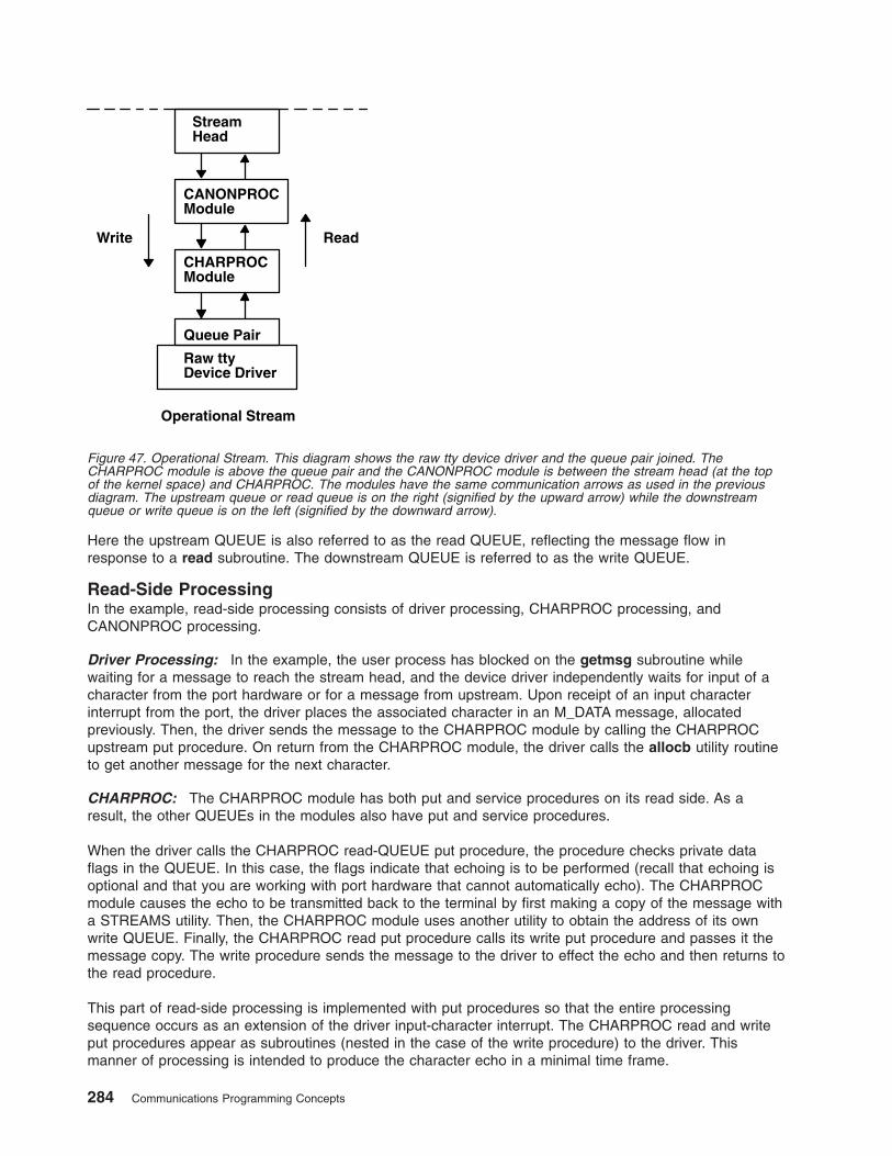
Here the upstream QUEUE is also referred to as the read QUEUE, reflecting the message flow in
response to a read subroutine. The downstream QUEUE is referred to as the write QUEUE.
Read-Side Processing
In the example, read-side processing consists of driver processing, CHARPROC processing, and
CANONPROC processing.
Driver Processing: In the example, the user process has blocked on the getmsg subroutine while
waiting for a message to reach the stream head, and the device driver independently waits for input of a
character from the port hardware or for a message from upstream. Upon receipt of an input character
interrupt from the port, the driver places the associated character in an M_DATA message, allocated
previously. Then, the driver sends the message to the CHARPROC module by calling the CHARPROC
upstream put procedure. On return from the CHARPROC module, the driver calls the allocb utility routine
to get another message for the next character.
CHARPROC: The CHARPROC module has both put and service procedures on its read side. As a
result, the other QUEUEs in the modules also have put and service procedures.
When the driver calls the CHARPROC read-QUEUE put procedure, the procedure checks private data
flags in the QUEUE. In this case, the flags indicate that echoing is to be performed (recall that echoing is
optional and that you are working with port hardware that cannot automatically echo). The CHARPROC
module causes the echo to be transmitted back to the terminal by first making a copy of the message with
a STREAMS utility. Then, the CHARPROC module uses another utility to obtain the address of its own
write QUEUE. Finally, the CHARPROC read put procedure calls its write put procedure and passes it the
message copy. The write procedure sends the message to the driver to effect the echo and then returns to
the read procedure.
This part of read-side processing is implemented with put procedures so that the entire processing
sequence occurs as an extension of the driver input-character interrupt. The CHARPROC read and write
put procedures appear as subroutines (nested in the case of the write procedure) to the driver. This
manner of processing is intended to produce the character echo in a minimal time frame.
StreamHead
CANONPROCModule
CHARPROCModule
Queue Pair
Raw ttyDevice Driver
Operational Stream
Write Read
Figure 47. Operational Stream. This diagram shows the raw tty device driver and the queue pair joined. The
CHARPROC module is above the queue pair and the CANONPROC module is between the stream head (at the top
of the kernel space) and CHARPROC. The modules have the same communication arrows as used in the previous
diagram. The upstream queue or read queue is on the right (signified by the upward arrow) while the downstream
queue or write queue is on the left (signified by the downward arrow).
284 Communications Programming Concepts
After returning from echo processing, the CHARPROC read put procedure checks another of its private
data flags and determines that parity checking should be performed on the input character. Usually, parity
would be checked as part of echo processing. However, for this example, parity is checked only when the
characters are sent upstream. As a result, parity checking can be deferred along with the canonical
processing. The CHARPROC module uses the putq utility to schedule the (original) message for
parity-check processing by its read service procedure. When the CHARPROC read service procedure is
complete, it forwards the message to the read put procedure of the CANONPROC module. If parity
checking were not required, the CHARPROC put procedure would call the CANONPROC put procedure
directly.
CANONPROC: The CANONPROC module performs canonical processing. As implemented, all read
QUEUE processing is performed in its service procedure. The CANONPROC put procedure calls the putq
utility to schedule the message for its read service procedure, and then exits. The service procedure
extracts the character from the message buffer and places it in the line buffer contained in another
M_DATA message it is constructing. Then, the message containing the single character is returned to the
buffer pool. If the character received was not an end-of-line, the CANONPROC module exits. Otherwise, a
complete line has been assembled and the CANONPROC module sends the message upstream to the
stream head, which unlocks the user process from the getmsg subroutine call and passes it the contents
of the message.
Write-Side Processing
The write side of the stream carries two kinds of messages from the user process: streamio messages for
the CHARPROC module and M_DATA messages to be output to the terminal.
The streamio messages are sent downstream as a result of an I_STR operation. When the CHARPROC
module receives a streamio message type, it processes the message contents to modify internal QUEUE
flags and then uses a utility to send an acknowledgment message upstream (read side) to the stream
head. The stream head acts on the acknowledgment message by unblocking the user from the streamio
message.
For terminal output, it is presumed that M_DATA messages, sent by write subroutines, contain multiple
characters. In general, STREAMS returns to the user process immediately after processing the write
subroutine so that the process may send additional messages. Flow control will eventually block the
sending process. The messages can queue on the write side of the driver because of
character-transmission timing. When a message is received by the driver’s write put procedure, the
procedure will use the putq utility to place the message on its write-side service message queue if the
driver is currently transmitting a previous message buffer. However, there is generally no write-QUEUE
service procedure in a device driver. Driver output-interrupt processing takes the place of scheduling and
performs the service procedure functions, removing messages from the queue.
Analysis
For reasons of efficiency, a module implementation would generally avoid placing one character per
message and using separate routines to echo and parity-check each character, as done in this example.
Nevertheless, even this design yields potential benefits. Consider a case in which an alternative and more
intelligent port hardware was substituted. If the hardware processed multiple input characters and
performed the echo and parity-checking functions of the CHARPROC module, then the new driver could
be implemented to present the same interface as the CHARPROC module. Other modules such as
CANONPROC could continue to be used without modification.
Differences Between Portable Streams Environment and V.4 STREAMS
Portable Streams Environment (PSE) was implemented from the AT&T UNIX System V Release 4,
Programmer’s Guide: STREAMS document. It is designed for compatibility with existing STREAMS
applications and modules that adhere to the STREAMS design guidelines.
Chapter 10. STREAMS 285
Extensions to STREAMS
In some areas, the STREAMS definition is extended to enhance functionality. These enhancements
include:
v Extended read modes. PSE supports an extra read mode, RFILL, which requests that the stream head
fill a buffer completely before returning to the application. This is used in conjunction with a cooperating
module and M_READ messages.
v The putctl2 utility. A new utility routine, putctl2, is supported for creating M_ERROR messages with 2
bytes of data. The parameters are the same as for the putctl1 utility.
v Autopush names. The PSE autopush command accepts device names in place of major numbers on
the command line. It then translates names into major numbers with the help of the sc module.
Note: Although these extensions can be used freely in this operating system, their use limits portability.
Differences in PSE
Although PSE is written to the specifications in the AT&T document, there are places in which compatibility
with the specification is not implemented or is not possible. These differences are:
v Include files. Not all structures and definitions in AT&T include files are discussed in the STREAMS
documentation. Module and application writers can use only those symbols specified in the
documentation.
v Module configuration. The configuration of modules and devices under PSE is different from AT&T
System V Release 4 in that there is no master file or related structures. PSE maintains an fmodsw table
for modules, and a dmodsw table for devices and multiplexors. Entries are dynamically placed in these
tables as modules are loaded into a running system. Similarly, PSE normally supports init routines for
modules and devices, but not start routines.
v Logging device. The STREAMS logging device is named /dev/slog. The /dev/log node refers to a
different type of logging device.
v Structure definitions. PSE supports the standard STREAMS structure definitions in terms of field names
and types, but also includes additional fields for host-specific needs. Modules and applications should
not depend on the field position or structure size as taken from STREAMS documentation. Also, PSE
does not support the notion of expanded fundamental types and the associated _STYPES definition.
v Queue flags. PSE defines, but does not implement, the QBACK and QHLIST queue flags.
v Memory allocation. PSE does not support the rmalloc, rminit, and rmfree memory allocation routines.
v Named streams. PSE does not support named streams and the associated fdetach program.
v Terminals. PSE does not include STREAMS-based terminals or the related modules and utilities
(including job control primitives). However, nothing in PSE prevents STREAMS-based terminals from
being added.
v Network selection. PSE does not support the V.4 Network Selection and Name-to-Address Mapping
extensions to the TLI (Transport Layer Interface).
List of Streams Commands
System management commands are arranged by the following functions:
v Configuring
v Maintaining
For information about STREAMS operations, modules and drivers, subroutines, a function, system calls,
and utilities, see “List of STREAMS Programming References” on page 287.
Configuring
autopush Configures lists of automatically pushed STREAMS modules.
286 Communications Programming Concepts
strchg Changes stream configuration.
strconf Queries stream configuration.
strload Loads and configures Portable Streams Environment (PSE).
Maintaining
scls Produces a list of module and driver names.
strace Prints STREAMS trace messages.
strclean Cleans up the STREAMS error logger.
strerr (Daemon) Receives error log messages from the STREAMS log driver.
List of STREAMS Programming References
The list includes:
v “Operation”
v “Modules and Drivers”
v “Subroutines”
v “Function” on page 288
v “System Calls” on page 288
v “Utilities” on page 288
For information about STREAMS commands for configuring and managing, see “List of Streams
Commands” on page 286.
Operation
streamio Lists the ioctl operations which perform a variety of control functions on streams.
Modules and Drivers
The following modules and drivers are used in the STREAMS environment. The references are found in
the list of subroutines.
pfmod Selectively removes upstream data messages on a stream.
timod Converts a set of streamio operations into STREAMS messages.
tirdwr Supports the Transport Interface functions of the Network Services library.
xtiso Provides access to sockets-based protocols to STREAMS applications.
dlpi Provides an interface to the data link provider.
Subroutines
t_accept Accepts a connect request.
t_alloc Allocates a library structure.
t_bind Binds an address to a transport endpoint.
t_close Closes a transport endpoint.
t_connect Establishes a connection with another transport user.
t_error Produces an error message.
t_free Frees a library structure.
t_getinfo Gets protocol-specific service information.
t_getstate Gets the current state.
t_listen Listens for a connect request.
Chapter 10. STREAMS 287
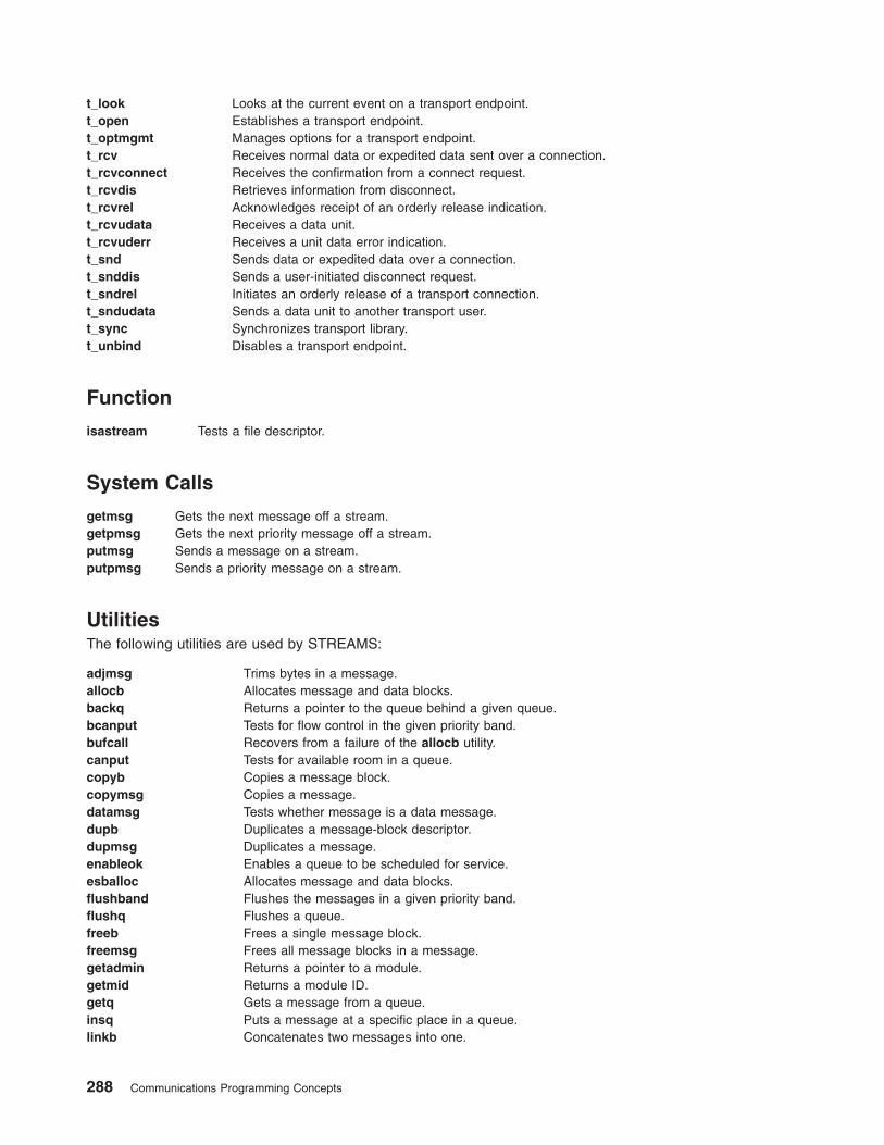
t_look Looks at the current event on a transport endpoint.
t_open Establishes a transport endpoint.
t_optmgmt Manages options for a transport endpoint.
t_rcv Receives normal data or expedited data sent over a connection.
t_rcvconnect Receives the confirmation from a connect request.
t_rcvdis Retrieves information from disconnect.
t_rcvrel Acknowledges receipt of an orderly release indication.
t_rcvudata Receives a data unit.
t_rcvuderr Receives a unit data error indication.
t_snd Sends data or expedited data over a connection.
t_snddis Sends a user-initiated disconnect request.
t_sndrel Initiates an orderly release of a transport connection.
t_sndudata Sends a data unit to another transport user.
t_sync Synchronizes transport library.
t_unbind Disables a transport endpoint.
Function
isastream Tests a file descriptor.
System Calls
getmsg Gets the next message off a stream.
getpmsg Gets the next priority message off a stream.
putmsg Sends a message on a stream.
putpmsg Sends a priority message on a stream.
Utilities
The following utilities are used by STREAMS:
adjmsg Trims bytes in a message.
allocb Allocates message and data blocks.
backq Returns a pointer to the queue behind a given queue.
bcanput Tests for flow control in the given priority band.
bufcall Recovers from a failure of the allocb utility.
canput Tests for available room in a queue.
copyb Copies a message block.
copymsg Copies a message.
datamsg Tests whether message is a data message.
dupb Duplicates a message-block descriptor.
dupmsg Duplicates a message.
enableok Enables a queue to be scheduled for service.
esballoc Allocates message and data blocks.
flushband Flushes the messages in a given priority band.
flushq Flushes a queue.
freeb Frees a single message block.
freemsg Frees all message blocks in a message.
getadmin Returns a pointer to a module.
getmid Returns a module ID.
getq Gets a message from a queue.
insq Puts a message at a specific place in a queue.
linkb Concatenates two messages into one.
288 Communications Programming Concepts
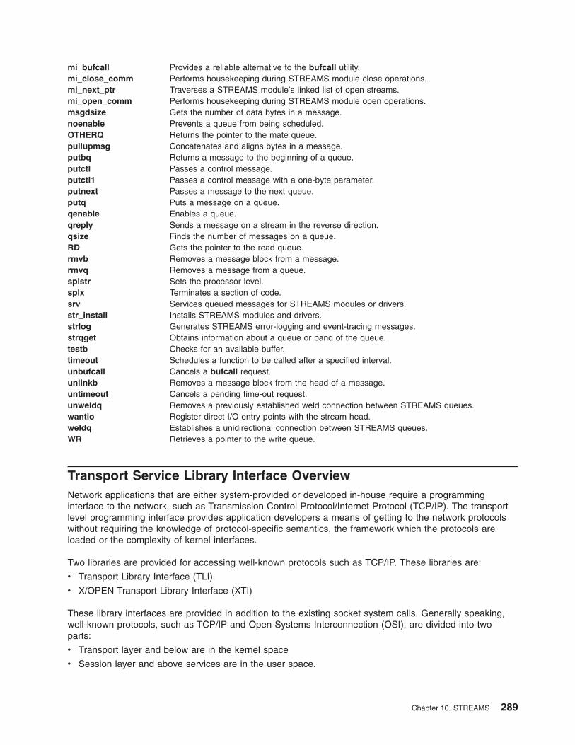
mi_bufcall Provides a reliable alternative to the bufcall utility.
mi_close_comm Performs housekeeping during STREAMS module close operations.
mi_next_ptr Traverses a STREAMS module’s linked list of open streams.
mi_open_comm Performs housekeeping during STREAMS module open operations.
msgdsize Gets the number of data bytes in a message.
noenable Prevents a queue from being scheduled.
OTHERQ Returns the pointer to the mate queue.
pullupmsg Concatenates and aligns bytes in a message.
putbq Returns a message to the beginning of a queue.
putctl Passes a control message.
putctl1 Passes a control message with a one-byte parameter.
putnext Passes a message to the next queue.
putq Puts a message on a queue.
qenable Enables a queue.
qreply Sends a message on a stream in the reverse direction.
qsize Finds the number of messages on a queue.
RD Gets the pointer to the read queue.
rmvb Removes a message block from a message.
rmvq Removes a message from a queue.
splstr Sets the processor level.
splx Terminates a section of code.
srv Services queued messages for STREAMS modules or drivers.
str_install Installs STREAMS modules and drivers.
strlog Generates STREAMS error-logging and event-tracing messages.
strqget Obtains information about a queue or band of the queue.
testb Checks for an available buffer.
timeout Schedules a function to be called after a specified interval.
unbufcall Cancels a bufcall request.
unlinkb Removes a message block from the head of a message.
untimeout Cancels a pending time-out request.
unweldq Removes a previously established weld connection between STREAMS queues.
wantio Register direct I/O entry points with the stream head.
weldq Establishes a unidirectional connection between STREAMS queues.
WR Retrieves a pointer to the write queue.
Transport Service Library Interface Overview
Network applications that are either system-provided or developed in-house require a programming
interface to the network, such as Transmission Control Protocol/Internet Protocol (TCP/IP). The transport
level programming interface provides application developers a means of getting to the network protocols
without requiring the knowledge of protocol-specific semantics, the framework which the protocols are
loaded or the complexity of kernel interfaces.
Two libraries are provided for accessing well-known protocols such as TCP/IP. These libraries are:
v Transport Library Interface (TLI)
v X/OPEN Transport Library Interface (XTI)
These library interfaces are provided in addition to the existing socket system calls. Generally speaking,
well-known protocols, such as TCP/IP and Open Systems Interconnection (OSI), are divided into two
parts:
v Transport layer and below are in the kernel space
v Session layer and above services are in the user space.
Chapter 10. STREAMS 289
The operating system supplies the socket-based TCP/IP protocol suites as a part of the base system. It
also supplies the socket system calls and socket library calls (libc.a) for the existing applications which
have been developed using the sockets applications programming interface (API).
TLI is a library that is used for porting applications developed using the AT&T System V-based UNIX
operating systems.
XTI is a library implementation, as specified by X/OPEN CAE Specification of X/Open Transport Interface
and fully conformant to X/OPEN XPG4 Common Application Environment (CAE) specification, that defines
a set of transport-level services that are independent of any specific transport provider’s protocol or its
framework.
The purpose of XTI is to provide a universal programming interface for the transport layer functions
regardless of the transport layer protocols, how the framework of the transport layer protocols are
implemented, or the type of UNIX operating system. For example, an application which writes to XTI
should not have to know that the service provider is written using STREAMS or sockets. The application
accesses the transport end point (using the returned handle, fd, of the t_open subroutine) and requests
and receives indications from the well-known service primitives. If desired or necessary, applications can
obtain any protocol-specific information by calls to the t_info subroutine.
Both TLI and XTI are implemented using STREAMS. This implementation includes the following members:
v Transport Library - libtli.a
v X/OPEN Transport Library - libxti.a
v STREAMS driver - Sends STREAMS messages initiated from the XTI or TLI library to the
sockets-based network protocol (as in the case of TCP/IP) or to other STREAMS drivers (as in the case
of Netware).
The TLI (libtli.a) and XTI (libxti.a) libraries are shared libraries. This means that applications can run
without recompiling, even though the system may update the libraries in the future.
The TLI and XTI calls syntax is similar. For the most part, XTI is a superset of TLI in terms of definitions,
clarification of usage, and robustness of return codes. For specific XTI usage and return codes, see the
X/OPEN CAE Specification of X/Open Transport Interface and the “Subroutines” on page 287.
TLI and XTI Characteristics
TLI and XTI are the interfaces for providing the transport layer services. The semantics of these interfaces
closely resemble those of sockets. Some of the characteristics of the interfaces are:
v Transport end points - A transport end point specifies a communication path between a transport user
and a specific transport provider. Similar to the socket subroutine (which returns the file descriptor, s),
calls to the TLI and XTI t_open subroutines return the file descriptor, fd, as a handle to be used with
subsequent calls.
A transport end point can support only one established transport connection at a time, though a
transport provider, such as TCP/IP, serves the multiple transport end points. To activate and bind the
local transport port, a transport end point must have a transport address associated with it by t_bind
subroutine calls. To make a end-to-end connection between two active transport end points, the
t_connect subroutine must follow. For a transport end point that needs a connectionless service, such
as User Datagram Protocol/Internet Protocol (UDP/IP), a connect phase is skipped and the t_rcvudata
subroutine can be called after the t_bind subroutine is issued.
v Ownership of transport end points - Once a transport end point is acquired from the transport
provider (by getting the file descriptor, fd, from the t_open calls), the handle as specified by fd can be
shared by multiple processes, such as the fork subroutine. However, the transport provider treats the
processes sharing the same fd as a single return point. These processes must coordinate their activities
to not violate the state of provider.
290 Communications Programming Concepts

The t_sync subroutine calls return the state of the transport provider, allowing users to verify the
transport provider state before taking further action. An application that wants to manage multiple
transport providers, such as a server application, must call the t_open subroutine for each provider. For
example, a server application that is waiting for incoming connect indications from several transport
providers, such as TCP/IP and OSI, must open multiple t_open subroutines and listen for connection
indications on each of the associated handles (fd).
v Synchronous and asynchronous execution of calls - TLI and XTI provide synchronous and
asynchronous execution of calls. In the synchronous mode of operation, the calls block until a specific
event is satisfied. Synchronous mode is the default mode of operation. In the asynchronous mode of
operation (t_open subroutine with the O_NONBLOCK flag set), the call is returned immediately and the
specified event is notified by either or both the poll and select system calls some time later.
Users are advised to choose a mode of execution based on the nature of its function. For example, a
typical server application should exploit the asynchronous execution to facilitate multiple concurrent
actions required for client requests.
v Event Management - For connection-oriented mode, it is important for users to know the state of the
current connection or the change of any state caused by calls issued to that state. The TLI and XTI
event management allows the state of event either by return code (TLOOK) or a call (t_look
subroutine) to request the current state information.
The following tables list the typical sequence of calls a user must issue for various connection types.
Note: These tables are provided as examples of typical sequences, rather than the exact order in which
the transport providers are required.
Connection oriented calls:
Server Client
t_open() t_open()
| |
t_bind() t_bind()
| |
t_alloc() t_alloc()
| |
t_listen() t_connect()
: <—————————-:
: :
t_accept() :
| :
t_rcv()/t_snd() t_snd()/t_rcv()
| |
t_snddis()/t_rcvdis() t_rcvdis()/t_snddis()
| |
t_unbind() t_unbind()
| |
t_close() t_close()
Chapter 10. STREAMS 291
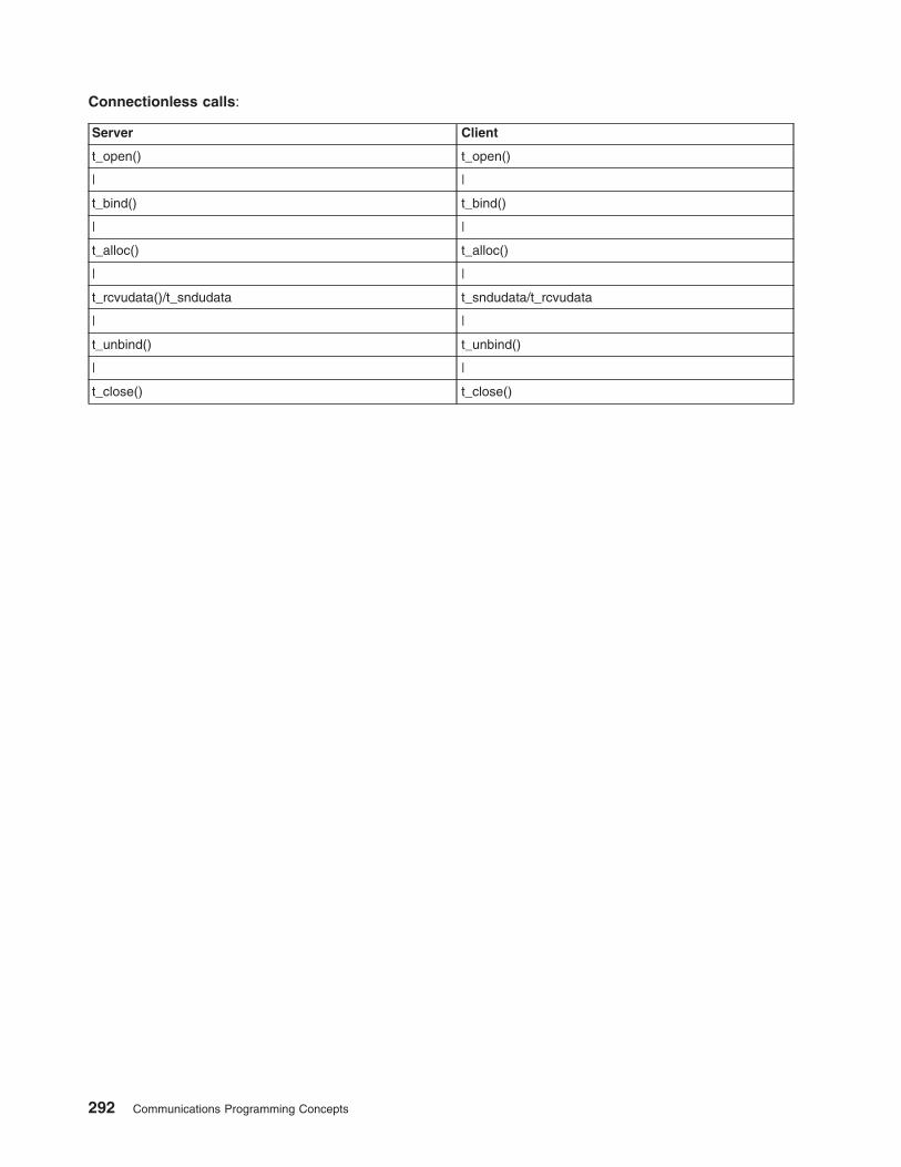
Connectionless calls:
Server Client
t_open() t_open()
| |
t_bind() t_bind()
| |
t_alloc() t_alloc()
| |
t_rcvudata()/t_sndudata t_sndudata/t_rcvudata
| |
t_unbind() t_unbind()
| |
t_close() t_close()
292 Communications Programming Concepts
Chapter 11. Transmission Control Protocol/Internet Protocol
Transmission Control Protocol/Internet Protocol (TCP/IP) includes a suite of protocols that specify
communications standards between computers as well as detail conventions for routing and
interconnecting networks. TCP/IP is used extensively on the Internet and consequently allows research
institutions, colleges and universities, government, industry, and individuals to communicate with each
other.
This chapter provides the following:
v “DHCP Server API”
v “Dynamic Load API” on page 299
v “Service Location Protocol (SLP) APIs” on page 303
v “Lists of Programming References” on page 307
For information on name resolution, see “Network Address Translation” on page 212.
DHCP Server API
The DHCP server lets you define modules that can be linked to the DHCP Server and called at specified
checkpoints during DHCP or BOOTP message processing. This section describes the following:
v “Loading User Objects”
v “Predefined Structures”
v “User-Defined Object Requirements” on page 295
v “User-Defined Object Optional Routine” on page 299
Note: Because the DHCP server is run with root-user authority, user-defined objects can introduce
security vulnerabilities and performance degradation. Especially protect against buffer overrun
exploitations and enforce security measures when an object writes to temporary files or executes
system commands. Also, since many of the routines that can be defined by the object are executed
during the normal processing path of each DHCP client’s message, monitor the response time to
the DHCP client for any impacts on performance.
Loading User Objects
The DHCP server loads any user-defined object referenced in the configuration file with the UserObject
configuration line or stanza. For example:
UserObject myobject
or
UserObject myobject
{
file /tmp/myobject.log;
}
For both of these examples, the dynamically loadable shared object myobject.dhcpo is loaded from the
/usr/sbin directory. In the second case, the object’s Initialize subroutine is passed a file pointer; the object
must parse and handle its own configuration stanza.
Predefined Structures
The operating system provides the following structures through the dhcp_api.h file. The structures are
more thoroughly described in the following sections:
v “dhcpmessage” on page 294
© Copyright IBM Corp. 1994, 2005 293
v “dhcpoption”
v “dhcpclientid”
v “dhcplogseverity”
dhcpmessage
dhcpmessage defines the structure and fields of a basic DHCP message. The options field is variable in
length and every routine that references a DHCP message also specifies the total length of the message.
The content of the structure follows:
struct dhcpmessage
{
uint8_t op;
uint8_t htype;
uint8_t hlen;
uint8_t hops;
uint32_t xid;
uint16_t secs;
uint16_t flags;
uint32_t ciaddr;
uint32_t yiaddr;
uint32_t siaddr;
uint32_t giaddr;
uint8_t chaddr[16];
uint8_t sname[64];
uint8_t file[128];
uint8_t options[1];
};
dhcpoption
dhcpoption defines the framework of a DHCP option encoded in its type, length, data format. The content
of the structure follows:
struct dhcpoption
{
uint8_t code;
uint8_t len;
uint8_t data[1];
};
dhcpclientid
dhcpclientid uniquely identifies a DHCP client. You can define it using the DHCP Client Identifier Option
or it can be created from the hardware type, hardware length, and hardware address of a DHCP or
BOOTP message that does not contain a Client Identifier Option. The DHCP message option and client
identifier references always point to network byte-ordered data. The content of the structure follows:
struct dhcpclientid
{
uint8_t type;
uint8_t len;
uint8_t id[64];
};
dhcplogseverity
The enumerated type dhcplogseverity assigns a log severity level to a user-defined object’s error
messages. An object’s error message is displayed to the DHCP server’s log file through the exported
dhcpapi_logmessage routine, provided that logging severity level has been enabled.
enum dhcplogseverity
{
dhcplog_syserr = 1 ,
dhcplog_objerr ,
dhcplog_protocol ,
dhcplog_warning ,
dhcplog_event ,
dhcplog_action ,
294 Communications Programming Concepts
dhcplog_info ,
dhcplog_accounting ,
dhcplog_stats ,
dhcplog_trace
};
User-Defined Object Requirements
The following are required for any user-defined object to conform to this API:
1. The object must use the Initialize routine (see “Initialize”).
2. The object must use the Shutdown routine (see “Shutdown”).
3. The object must contain at least one of the checkpoint routines defined in the API (see “Checkpoint
Routines” on page 296).
4. The object must never alter any data provided by a const pointer reference to the routine.
Initialize
The Initialize routine must be defined by the object to be loaded by the server. It is used each time the
server is started, including restarts, and is called each time the object is referenced in the DHCP server’s
configuration file.
The following is the structure of the Initialize routine:
int Initialize ( FILE *fp,
caddr_t *hObjectInstance ) ;
Where:
fp Points to the configuration block for the loaded UserObject. The value of the pointer is NULL
if no configuration block exists following the UserObject definition in the DHCP Server
configuration file.
hObjectInstance Is set by the loaded object if the object requires private data to be returned to it through each
invocation. One handle is created for each configuration instance of the loaded object.
If the file pointer fp is not NULL, its initial value references the first line of contained data within the
configuration block of the user-defined object. Parsing should continue only as far as an unmatched close
brace (}), which indicates the end of the configuration block.
The Initialize routine does not require setting the hObjectInstance handle. However, it is required that the
routine return specific codes, depending on whether the initialization succeeded or failed. The required
codes and their meanings follow:
0 (zero) Instance is successfully initialized. The server can continue to link to each symbol.
!= 0 (non-zero) Instance failed to initialize. The server can free its resources and continue to load, ignoring
this section of the configuration file.
Shutdown
The Shutdown routine is used to reverse the effects of initialization: to deallocate data and to destroy
threads. The Shutdown routine is called before shutting down the server and again before reloading the
configuration file at each server reinitialization. The routine must return execution to the server so the
server can reinitialize and properly shut down. The following is the structure of the Shutdown routine:
void Shutdown ( caddr_t hObjectInstance ) ;
Where:
hObjectInstance Is the same configuration instance handle created when this object was initialized.
Chapter 11. Transmission Control Protocol/Internet Protocol 295
Checkpoint Routines
A user-defined object must implement at least one of the following checkpoint routines. The routines are
more thoroughly described in the following sections.
v “messageReceived”
v “addressOffered”
v “addressAssigned” on page 297
v “addressReleased” on page 297
v “addressExpired” on page 298
v “addressDeleted” on page 298
v “addressDeclined” on page 298
messageReceived: The messageReceived routine lets you add an external means of authentication to
each received DHCP or BOOTP message. The routine is called just as the message is received by the
protocol processor and before any parsing of the message itself.
In addition to the message, the server passes three IP addresses to the routine. These addresses, when
used together, can determine whether the client is on a locally attached network or a remotely routed
network and whether the server is receiving a broadcast message.
Additionally, you can use the messageReceived routine to alter the received message. Because changes
directly affect the remainder of message processing, use this ability rarely and only under well-understood
circumstances.
The following is the structure of the messageReceived routine:
int messageReceived ( caddr_t hObjectInstance,
struct dhcpmessage **inMessage,
size_t *messageSize,
const struct in_addr *receivingIP,
const struct in_addr *destinationIP,
const struct in_addr *sourceIP ) ;
Where:
hObjectInstance Is the same configuration instance handle created when this object was initialized.
inMessage Is a pointer to the unaltered, incoming DHCP or BOOTP message.
messageSize Is the total length, in bytes, of the received DHCP or BOOTP message.
receivingIP Is the IP address of the interface receiving the DHCP or BOOTP message.
destinationIP Is the destination IP address taken from the IP header of the received DHCP or BOOTP
message.
sourceIP Is the source IP address taken from the IP header of the received DHCP or BOOTP
message.
The messageReceived routine returns one of the following values:
0 (zero) The received message can continue to be parsed and the client possibly offered or given an
address through the regular means of the DHCP server.
!= 0 (non-zero) The source client of this message is not to be given any response from this server. This
server remains silent to the client.
addressOffered: The addressOffered routine is used for accounting. Parameters passed to the routine
are read-only. The routine has no return code to prevent sending the outgoing message. It is called when
a DHCP client is ready to be sent an address OFFER message. The following is the structure of the
addressOffered routine:
296 Communications Programming Concepts
void addressOffered ( caddr_t hObjectInstance,
const struct dhcpclientid *cid,
const struct in_addr *addr,
const struct dhcpmessage *outMessage,
size_t messageSize ) ;
Where:
hObjectInstance Is the same configuration instance handle created when this object was initialized.
cid Is the client identifier of the client.
addr Is the address to be offered to the client.
outMessage Is the outgoing message that is ready to be sent to the client.
messageSize Is the length, in bytes, of the outgoing message that is ready to be sent to the client.
addressAssigned: The addressAssigned routine can be used for accounting purposes or to add an
external means of name and address association. The hostname and domain arguments are selected
based upon the A-record proxy update policy and the append domain policy (configured in the db_file
database through the keywords proxyARec and appendDomain, respectively), as well as the defined and
suggested hostname and domain options for the client.
The addressAssigned routine is called after the database has associated the address with the client and
just before sending the BOOTP response or DHCP ACK to the client. If a DNS update is configured, the
addressAssigned routine is called after the update has occurred or, at least, has been queued.
Parameters offered to the routine are read-only. The routine has no return code to prevent address and
client binding. The structure of the addressAssigned routine follows:
void addressAssigned ( caddr_t hObjectInstance,
const struct dhcpclientid *cid,
const struct in_addr *addr,
const char *hostname,
const char *domain,
const struct dhcpmessage *outMessage,
size_t messageSize ) ;
hObjectInstance Is the same configuration instance handle created when this object was initialized.
cid Is the client identifier of the client.
addr Is the address selected for the client.
hostname Is the host name which is (or should have been) associated with the client.
domain Is the domain in which the host name for the client was (or should have been) updated.
outMessage Is the outgoing message that is ready to be sent to the client.
messageSize Is the length, in bytes, of the outgoing message that is ready to be sent to the client.
addressReleased: The addressReleased routine is used for accounting when DHCP clients are ready
to be sent an address OFFER message. Parameters given to the routine are read-only.
The routine is called just after the database has been instructed to disassociate the client identifier and
address binding. If so configured, the routine is called after the DNS server has been indicated to
disassociate the name and address binding.
The structure of the addressReleased routine follows:
void addressReleased ( caddr_t hObjectInstance,
const struct dhcpclientid *cid,
const struct in_addr *addr,
const char *hostname,
const char *domain ) ;
Chapter 11. Transmission Control Protocol/Internet Protocol 297
Where:
hObjectInstance Is the same configuration instance handle created when this object was initialized.
cid Is the client identifier of the client.
addr Is the address previously used by the client.
hostname Is the hostname previously associated with this client and address binding.
domain Is the domain in which the hostname for the client was (or should have been) previously
updated.
addressExpired: The addressExpired routine is used for accounting when any DHCP database detects
an association must be cancelled because the address and client identifier association has existed beyond
the end of the offered lease. Parameters given to the routine are read-only.
The structure of the addressExpired routine follows:
void addressExpired ( caddr_t hObjectInstance,
const struct dhcpclientid *cid,
const struct in_addr *addr,
const char *hostname,
const char *domain ) ;
Where:
hObjectInstance Is the same configuration instance handle created when this object was initialized.
cid Is the client identifier of the client.
addr Is the address previously used by the client.
hostname Is the hostname previously associated with this client and address binding.
domain Is the domain in which the hostname for the client was (or should have been) previously
updated.
addressDeleted: The addressDeleted routine is used for accounting when any address association is
explicitly deleted from lack of interaction with the client or because of a lease expired. Most commonly, this
routine is invoked when the DHCP server is reinitialized, when a new configuration might cause a previous
client and address association to become invalid, or when the administrator explicitly deletes an address
using the dadmin command. Parameters given to the routine are read-only.
The structure of the addressDeleted routine follows:
void addressDeleted ( caddr_t hObjectInstance,
const struct dhcpclientid *cid,
const struct in_addr *addr,
const char *hostname,
const char *domain ) ;
Where:
hObjectInstance Is the same configuration instance handle created when this object was initialized.
cid Is the client identifier of the client.
addr Is the address previously used by the client.
hostname Is the hostname previously associated with this client and address binding.
domain Is the domain in which the hostname for the client was (or should have been) previously
updated.
addressDeclined: The addressDeclined routine is used for accounting purposes when a DHCP client
indicates to the server (through the DHCP DECLINE message type) that the given address is in use on
the network. The routine is called immediately after the database has been instructed to disassociate the
client identifier and address binding. If so configured, the routine is called after the DNS server has been
indicated to disassociate the name and address binding. Parameters given to the routine are read-only.
298 Communications Programming Concepts
The structure of the addressDeclined routine follows:
void addressDeclined ( caddr_t hObjectInstance,
const struct dhcpclientid *cid,
const struct in_addr *addr,
const char *hostname,
const char *domain ) ;
Where:
hObjectInstance Is the same configuration instance handle created when this object was initialized.
cid Is the client identifier of the client.
addr Is the address that was declined by the client.
hostname Is the hostname previously associated with this client and address binding.
domain Is the domain in which the hostname for the client was (or should have been) previously updated.
User-Defined Object Optional Routine
The dhcpapi_logmessage routine is available to the user-defined object programmer. A prototype is
available in dhcpapi.h with the symbol defined for linking in /usr/lib/dhcp_api.exp.
The routine specifies a message that is logged to the DHCP server’s configured log file, provided that
message severity level, which specified by the s parameter, has been enabled. The structure of the
dhcpapi_logmessage routine follows:
void dhcpapi_logmessage ( enum dhcplogseverity s,
char *format,
... ) ;
s Is the severity level of the message to be logged. Message severities are defined in the dhcpapi.h
header file and correspond directly to the DHCP server configuration logItem levels of logging.
format Is the typical printf format string.
Dynamic Load API
The operating system supports name resolution from five different maps:
v Domain Name Server (DNS)
v Network Information Server (NIS)
v NIS+
v Local methods of name resolution
v Dynamically loaded, user-defined APIs
With the Dynamic Load Application Programming Interface (API), you can load your own modules to
provide routines that supplement the maps provided by the operating system. The Dynamic Load API
enables you to create dynamically loading APIs in any of the following map classes:
v “Services Map Type” on page 300
v “Protocols Map Type” on page 300
v “Hosts Map Type” on page 300
v “Networks Map Type” on page 300
v “Netgroup Map Type” on page 301
You can build your own user modules containing APIs for any or all of the map classes. The following
sections define an API’s function names and prototypes for each of the five classes. To instantiate each
map accesssor, the operating system requires that a user-provided module use the specified function
names and function prototypes for each map class.
Chapter 11. Transmission Control Protocol/Internet Protocol 299
For information about configuring a dynamically loading API, see “Configuring a Dynamic API” on page
302.
Services Map Type
The following is the required prototype for a user-defined services map class:
void *sv_pvtinit();
void sv_close(void *private);
struct servent * sv_byname(void *private, const char *name, const char *proto);
struct servent * sv_byport(void *private, int port, const char *proto);
struct servent * sv_next(void *private);
void sv_rewind(void *private);
void sv_minimize(void *private);
Function sv_pvtinit must exist. It is not required to return anything more than NULL. For example, the
function can return NULL if the calling routine does not need private data.
Functions other than sv_pvtinit are optional for this class. The module can provide none or only part of
the optional functions in its definition.
Protocols Map Type
The following is the required prototype for a user-defined protocols map class:
void * pr_pvtinit();
void pr_close(void *private);
struct protoent * pr_byname(void *private, const char *name);
struct protoent * pr_bynumber(void *private, int num);
struct protoent * pr_next(void *private);
void pr_rewind(void *private);
void pr_minimize(void *private);
Function pr_pvtinit must exist. It is not required to return anything more than NULL. For example, the
function can return NULL if the calling routine does not need private data.
Functions other than pr_pvtinit are optional for this class. The module can provide none or only part of
the optional functions in its definition.
Hosts Map Type
The following is the required prototype for a user-defined hosts map class:
void * ho_pvtinit();
void ho_close(void *private);
struct hostent * ho_byname(void *private, const char *name);
struct hostent * ho_byname2(void *private, const char *name, int af);
struct hostent * ho_byaddr(void *private, const void *addr, size_t len, int af);
struct hostent * ho_next(void *private);
void ho_rewind(void *private);
void ho_minimize(void *private);
Function ho_pvtinit must exist. It is not required to return anything more than NULL. For example, the
function can return NULL if the calling routine does not need private data.
Functions other than ho_pvtinit are optional for this class. The module can provide none or only part of
the optional functions in its definition.
Networks Map Type
The following is the required prototype for a user-defined networks map class:
void * nw_pvtinit();
void nw_close(void *private);
struct nwent * nw_byname(void *private, const char *name, int addrtype);
300 Communications Programming Concepts
struct nwent * nw_byaddr(void *private, void *net, int length, int addrtype);
struct nwent * nw_next(void *private);
void nw_rewind(void *private);
void nw_minimize(void *private);
Function nw_pvtinit must exist. It is not required to return anything more than NULL. For example, the
function can return NULL if the calling routine does not need private data.
Functions other than nw_pvtinit are optional for this class. The module can provide none or only part of
the optional functions in its definition.
The operating system provides a data structure required to implement the networks map class, which uses
this structure to communicate with the operating system.
struct nwent {
char *name; /* official name of net */
char **n_aliases; /* alias list */
int n_addrtype; /* net address type */
void *n_addr; /* network address */
int n_length; /* address length, in bits */
};
Netgroup Map Type
The following is the required prototype for a user-defined netgroup map class:
void * ng_pvtinit();
void ng_rewind(void *private, const char *group);
void ng_close(void *private);
int ng_next(void *private, char **host, char **user, char **domain);
int ng_test(void *private, const char *name, const char *host, const char *user,
const char *domain);
void ng_minimize(void *private);
Function ng_pvtinit must exist. It is not required to return anything more than NULL. For example, the
function can return NULL if the calling routine does not need private data.
Functions other than ng_pvtinit are optional for this class. The module can provide none or only part of
the optional functions in its definition.
Using the Dynamic Load API
You must name your user-defined module according to a pre-established convention. Also, you must
configure it into the operating system before it will work. The following sections explain API module naming
and configuration.
Naming the User-Provided Module
The names of modules containing user-defined APIs follow this general form:
NameAddressfamily
Chapter 11. Transmission Control Protocol/Internet Protocol 301
Where:
Name Is the name of the dynamic loadable module name. The length of the Name can be between one
to eight characters.
The following key words are reserved as the user option name and may not be used as the name
of the dynamically loadable module:
v local
v bind
v dns
v nis
v ldap
v nis_ldap
Addressfamily Represents the address family and can be either 4 or 6. If no number is specified, the address
family is AF_UNSPEC. If the number is 4, the address family is AF_INET. If the number is 6, the
address family is AF_INET6.
Any other format for user options is not valid.
Note: If a user calls the gethostbyname2 system call from within the application, whatever the
address family the user passed to the gethostbyname2 system call overwrites the address family
in the user option. For example, a user option is david6 and there is a system call
gethostbyname2(name, AF_INET) in the application. Given this example, the address family
AF_INET overwrites the user option’s address family (6, same as AF_INET6).
Configuring a Dynamic API
There are three ways to specify user-provided, dynamically loading resolver routines. You can use the
NSORDER environment variable, the /etc/netsvc.conf configuration file, or the /etc/irs.conf configuration
file. With any of these sources, you are not restricted in the number of options that you can enter, nor in
the sequence in which they are entered. You are, however, restricted to a maximum number of 16 user
modules that a user can specify from any of these sources.
The NSORDER environemnt variable is given the highest priority. Next is the /etc/netsvc.conf
configuration file, then the /etc/irs.conf configuration file. A user option specified in a higher priority source
(for example, NSORDER) causes any user options specified in the lower priority sources to be ignored.
NSORDER Environment Variable
You can specify zero or more user options in the environment variable NSORDER. For example,
on the command line, you can type:
export NSORDER=local, bind, bob, nis, david4, jason6
In this example, the operating system invokes the listed name resolution modules, left to right, until
the name is resolved. The modules named local, bind, and nis are reserved by the operating
system, but bob, david4, and jason6 are user-provided modules.
/etc/netsvc.conf Configuration File
You can specify zero or more user options in the configuration file /etc/netsvc.conf. For example:
hosts=nis, jason4, david, local, bob6, bind
/etc/irs.conf Configuration File
You can specify zero or more user options in the configuration file /etc/irs.conf. For example:
hosts dns continue
hosts jason6 merge
hosts david4
302 Communications Programming Concepts
Procedures
To create and install a module containing a dynamically loading API, use the following procedure. The
operating system provides a sample Makefile, sample export file, and sample user module file, which are
located in the /usr/samples/tcpip/dynload directory.
1. Create the dynamic loadable module based on operating system specifications.
2. Create an export file (for example, rnd.exp) that exports all the symbols to be used.
3. After compilation, put all the dynamic loadable object files in the /usr/lib/netsvc/dynload directory.
4. Configure one of the sources described immediately before htis procedure (NSORDER,
/etc/netsvc.conf, or /etc/irs.conf).
Service Location Protocol (SLP) APIs
Service Location Protocol provides a flexible and scalable framework for providing hosts with access to
information about the existence, location, and configuration of network services. Any TCP/IP application
can take advantage of this protocol. SLP is based on RFC 2608 and RFC 2614.
This sections shows sample code on how to use the SLP APIs. The SLP APIs are as follows.
Documentation for these APIs can be found in AIX 5L Version 5.3 Technical Reference: Communications
Volume 2.
v SLPOpen
v SLPClose
v SLPFree
v SLPFindSrvs
v SLPFindSrvTypes
v SLPFindAttrs
v SLPEscape
v SLPUnescape
v SLPParseSrvURL
v SLPFindScopes
v SLPGetProperty
v SLPSrvTypeCallback
v SLPSrvURLCallback
v SLPAttrCallback * To compile it this sample code:
* cc -o samplecode samplecode.c -lslp
*
* To run the program:
* samplecode -s <scopes> -p <predicate> -a <attrids> -t <service_type> \
-u <url_string> -n <naming_authority>
*/
#include <stdio.h>
#include <slp.h>
extern int optind;
extern char *optarg;
int s_flag = 0,
p_flag = 0,
a_flag = 0,
t_flag = 0,
u_flag = 0,
n_flag = 0;
void arginit(int argc, char *argv[]);
Chapter 11. Transmission Control Protocol/Internet Protocol 303
void Usage(void);
char *service_type = NULL, /* For service type
*/
scopes = NULL, /* For scopes list
*/
*predicate = NULL, /* For precicate list
*/
*attrids = NULL, /* For attribute ids
*/
*url = NULL, /* For URL string
*/
*na = NULL; /* For naming authority string
*/
SLPBoolean SrvURLCallback (SLPHandle hslp,
const char *pcSrvURL,
unsigned short sLifetime,
SLPError errCode,
void *pvCookie)
{
SLPSrvURL* ppSrvURL;
SLPError err;
if ( errCode == SLP_LAST_CALL)
{
*(SLPError *) pvCookie = errCode;
return (SLP_FALSE); /* last call, no more data available */
}
else if (errCode != SLP_OK)
{
*(SLPError *) pvCookie = errCode;
return (SLP_FALSE); /* error happened. don’t want any more
data */
}
else
{
printf("pcSrvURL is: %s\n", pcSrvURL);
printf("sLifetime is: %d\n", sLifetime);
*(SLPError *) pvCookie = errCode;
/* Will parse the pcSrvURL string. */
err = SLPParseSrvURL((char *)pcSrvURL, &ppSrvURL);
if (err != SLP_OK)
{
SLPFree((void *)ppSrvURL); /* release the dynamically
allocated memory */
return(SLP_FALSE); /* don’t want any more data */
}
SLPFree((void *)ppSrvURL); /* release the dynamically allocated
memory */
return(SLP_TRUE); /* want more data */
}
}
SLPBoolean SrvTypeCallback (SLPHandle hslp,
const char *pcSrvTypes,
SLPError errCode,
void *pvCookie)
{
if ( errCode == SLP_LAST_CALL)
{
*(SLPError *) pvCookie = errCode;
return (SLP_FALSE); /* last call, no more data available
*/
}
304 Communications Programming Concepts
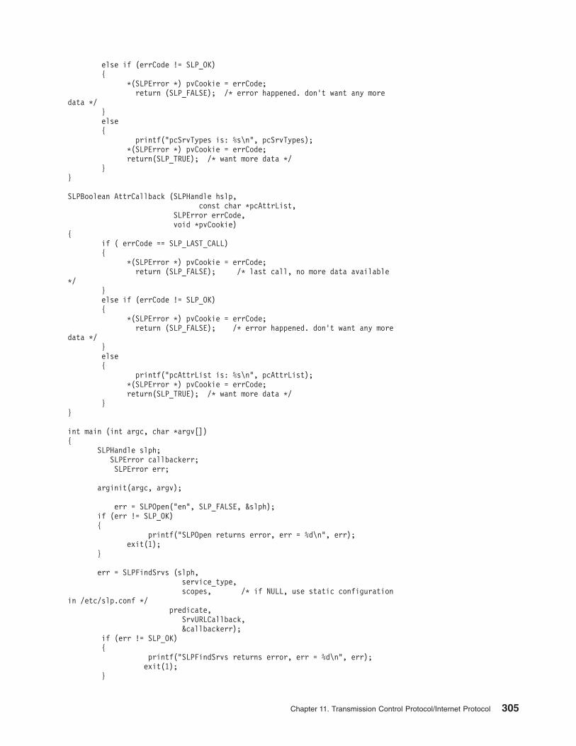
else if (errCode != SLP_OK)
{
*(SLPError *) pvCookie = errCode;
return (SLP_FALSE); /* error happened. don’t want any more
data */
}
else
{
printf("pcSrvTypes is: %s\n", pcSrvTypes);
*(SLPError *) pvCookie = errCode;
return(SLP_TRUE); /* want more data */
}
}
SLPBoolean AttrCallback (SLPHandle hslp,
const char *pcAttrList,
SLPError errCode,
void *pvCookie)
{
if ( errCode == SLP_LAST_CALL)
{
*(SLPError *) pvCookie = errCode;
return (SLP_FALSE); /* last call, no more data available
*/
}
else if (errCode != SLP_OK)
{
*(SLPError *) pvCookie = errCode;
return (SLP_FALSE); /* error happened. don’t want any more
data */
}
else
{
printf("pcAttrList is: %s\n", pcAttrList);
*(SLPError *) pvCookie = errCode;
return(SLP_TRUE); /* want more data */
}
}
int main (int argc, char *argv[])
{
SLPHandle slph;
SLPError callbackerr;
SLPError err;
arginit(argc, argv);
err = SLPOpen("en", SLP_FALSE, &slph);
if (err != SLP_OK)
{
printf("SLPOpen returns error, err = %d\n", err);
exit(1);
}
err = SLPFindSrvs (slph,
service_type,
scopes, /* if NULL, use static configuration
in /etc/slp.conf */
predicate,
SrvURLCallback,
&callbackerr);
if (err != SLP_OK)
{
printf("SLPFindSrvs returns error, err = %d\n", err);
exit(1);
}
Chapter 11. Transmission Control Protocol/Internet Protocol 305
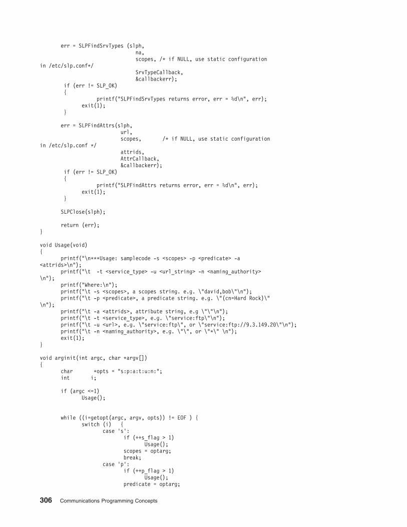
err = SLPFindSrvTypes (slph,
na,
scopes, /* if NULL, use static configuration
in /etc/slp.conf*/
SrvTypeCallback,
&callbackerr);
if (err != SLP_OK)
{
printf("SLPFindSrvTypes returns error, err = %d\n", err);
exit(1);
}
err = SLPFindAttrs(slph,
url,
scopes, /* if NULL, use static configuration
in /etc/slp.conf */
attrids,
AttrCallback,
&callbackerr);
if (err != SLP_OK)
{
printf("SLPFindAttrs returns error, err = %d\n", err);
exit(1);
}
SLPClose(slph);
return (err);
}
void Usage(void)
{
printf("\n***Usage: samplecode -s <scopes> -p <predicate> -a
<attrids>\n");
printf("\t -t <service_type> -u <url_string> -n <naming_authority>
\n");
printf("Where:\n");
printf("\t -s <scopes>, a scopes string. e.g. \"david,bob\"\n");
printf("\t -p <predicate>, a predicate string. e.g. \"(cn=Hard Rock)\"
\n");
printf("\t -a <attrids>, attribute string, e.g \"\"\n");
printf("\t -t <service_type>, e.g. \"service:ftp\"\n");
printf("\t -u <url>, e.g. \"service:ftp\", or \"service:ftp://9.3.149.20\"\n");
printf("\t -n <naming_authority>, e.g. \"\", or \"*\" \n");
exit(1);
}
void arginit(int argc, char *argv[])
{
char *opts = "s:p:a:t:u:n:";
int i;
if (argc <=1)
Usage();
while ((i=getopt(argc, argv, opts)) != EOF ) {
switch (i) {
case ’s’:
if (++s_flag > 1)
Usage();
scopes = optarg;
break;
case ’p’:
if (++p_flag > 1)
Usage();
predicate = optarg;
306 Communications Programming Concepts
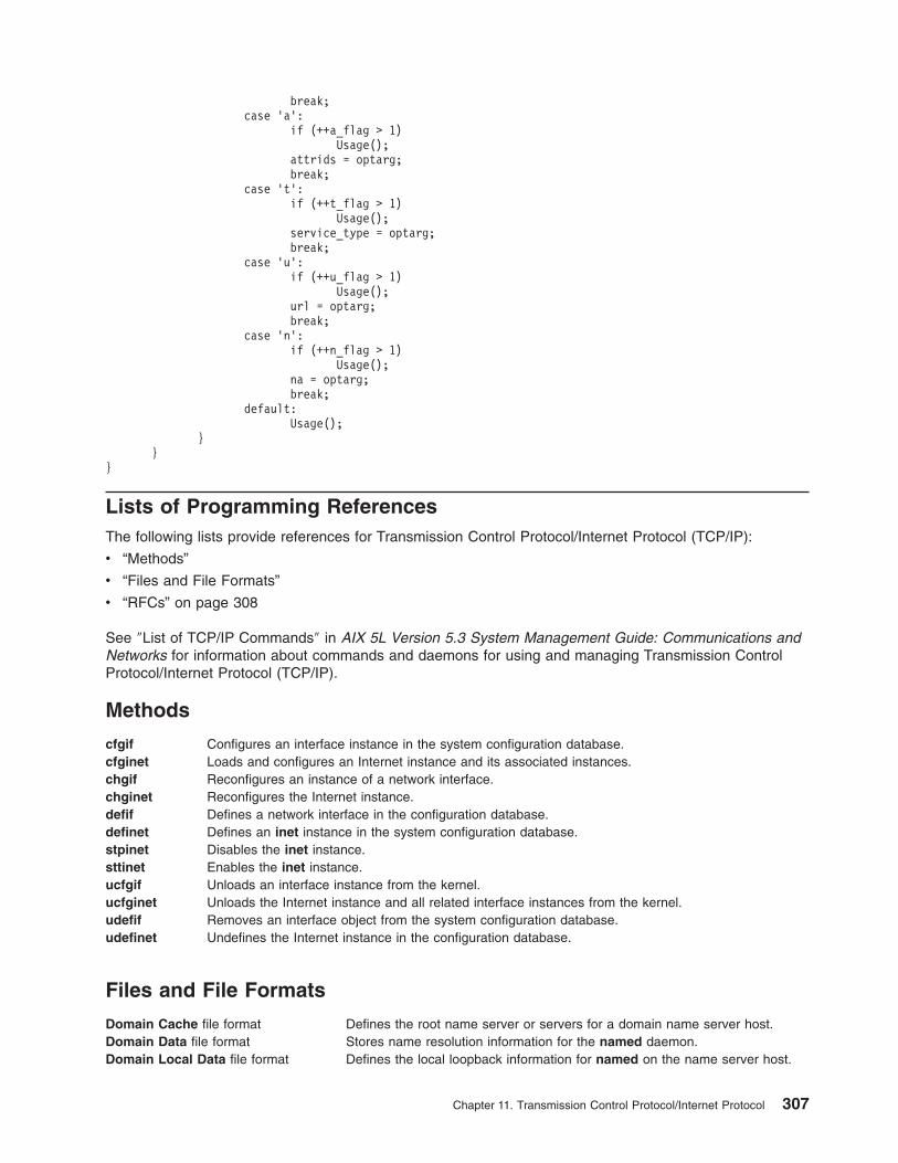
break;
case ’a’:
if (++a_flag > 1)
Usage();
attrids = optarg;
break;
case ’t’:
if (++t_flag > 1)
Usage();
service_type = optarg;
break;
case ’u’:
if (++u_flag > 1)
Usage();
url = optarg;
break;
case ’n’:
if (++n_flag > 1)
Usage();
na = optarg;
break;
default:
Usage();
}
}
}
Lists of Programming References
The following lists provide references for Transmission Control Protocol/Internet Protocol (TCP/IP):
v “Methods”
v “Files and File Formats”
v “RFCs” on page 308
See ″List of TCP/IP Commands″ in AIX 5L Version 5.3 System Management Guide: Communications and
Networks for information about commands and daemons for using and managing Transmission Control
Protocol/Internet Protocol (TCP/IP).
Methods
cfgif Configures an interface instance in the system configuration database.
cfginet Loads and configures an Internet instance and its associated instances.
chgif Reconfigures an instance of a network interface.
chginet Reconfigures the Internet instance.
defif Defines a network interface in the configuration database.
definet Defines an inet instance in the system configuration database.
stpinet Disables the inet instance.
sttinet Enables the inet instance.
ucfgif Unloads an interface instance from the kernel.
ucfginet Unloads the Internet instance and all related interface instances from the kernel.
udefif Removes an interface object from the system configuration database.
udefinet Undefines the Internet instance in the configuration database.
Files and File Formats
Domain Cache file format Defines the root name server or servers for a domain name server host.
Domain Data file format Stores name resolution information for the named daemon.
Domain Local Data file format Defines the local loopback information for named on the name server host.
Chapter 11. Transmission Control Protocol/Internet Protocol 307
Domain Reverse Data file format Stores reverse name resolution information for the named daemon.
ftpusers file format Specifies local user names that cannot be used by remote File Transfer
Protocol (FTP) clients.
gated.conf file format Contains configuration information for the gated daemon.
gateways file format Specifies Internet routing information to the routed and gated daemons on a
network.
hosts file format Defines the Internet Protocol (IP) name and address of the local host and
specifies the names and addresses of remote hosts.
hosts.equiv file format Specifies remote systems that can execute commands on the local system.
hosts.lpd file format Specifies remote hosts that can print on the local host.
inetd.conf file format Defines how the inetd daemon handles Internet service requests.
map3270 file format Defines a user keyboard mapping and colors for the tn3270 command.
named.conf file format Defines how named initializes the domain name server file.
.netrc file format Specifies automatic login information for the ftp and rexec commands.
networks file format Contains the network name file.
protocols file format Defines the Internet protocols used on the local host.
rc.net file format Defines host configuration for the following areas: network interfaces, host
name, default gateway, and any static routes.
rc.tcpip file Initializes daemons at each system startup.
resolv.conf file format Defines domain name server information for local resolver routines.
.rhosts file format Specifies remote users that can use a local user account on a network.
services file format Defines the sockets and protocols used for Internet services.
Standard Resource Record Format Defines the format of lines in the DOMAIN data files.
telnet.conf file format Translates a client’s terminal-type strings into terminfo file entries.
.3270keys file format Defines the default keyboard mapping and colors for the tn and telnet
commands.
RFCs
The list of Requests for Comments (RFCs) for TCP/IP includes:
v “Name Server”
v “Telnet” on page 309
v “FTP” on page 309
v “TFTP” on page 309
v “SNMP” on page 309
v “SMTP” on page 309
v “Name/Finger” on page 309
v “Time” on page 309
v “TCP” on page 309
v “UDP” on page 309
v “ARP” on page 309
v “IP” on page 310
v “ICMP” on page 310
v “Link (802.2)” on page 310
v “IP Multicasts” on page 211
v “Others” on page 310
Name Server
v Mail Routing and the Domain System, RFC 974, C. Partridge
v Domain Administrator’s Guide, RFC 1032, M. Stahl
v Domain Administrator’s Operations Guide, RFC 1033, M. Lottor
308 Communications Programming Concepts
v Domain Names—Concepts and Facilities, RFC 1034, P. Mockapetris
v Domain Names—Implementations and Specification, RFC 1035, P. Mockapetris
v Requirements for Internet Hosts—Application and Support, RFC 1123, R. Braden, ed.
Telnet
v Telnet Protocol Specification, RFC 854, J. Postel, J. Reynolds
v Telnet Option Specifications, RFC 855, J. Postel, J. Reynolds
v Telnet Binary Transmission, RFC 856, J. Postel, J. Reynolds
v Telnet Echo Option, RFC 857, J. Postel, J. Reynolds
v Telnet Suppresses Go Ahead Option, RFC 858, J. Postel, J. Reynolds
v Telnet Timing Mark Option, RFC 860, J. Postel, J. Reynolds
v Telnet Window Size Option, RFC 1073, D. Waitzman
v Telnet Terminal Type Option, RFC 1091, J. Von Bokkelen
v Requirements for Internet Hosts—Application and Support, RFC 1123, R. Braden, ed.
FTP
v File Transfer Protocol, RFC 959, J. Postel
v Requirements for Internet Hosts—Application and Support, RFC 1123, R. Braden, ed.
TFTP
v Trivial File Transfer Protocol, RFC 783, K. R. Sollins
v Requirements for Internet Hosts—Application and Support, RFC 1123, R. Braden, ed.
SNMP
See “Simple Network Management Protocol” on page 119.
SMTP
v Simple Mail Transfer Protocol, RFC 821, J. Postel
v Mail Routing and the Domain System, RFC 974, C. Partridge
v Requirements for Internet Hosts—Application and Support, RFC 1123, R. Braden, ed.
Name/Finger
v Name/Finger, RFC 742, K. Harrenstien
Time
v Time Protocol, RFC 868, J. Postel, K. Harrenstien
TCP
v Transmission Control Protocol, RFC 793, J. Postel
v Requirements for Internet Hosts—Communication Layers, RFC 1122, R. Braden, ed.
v TCP Extensions for High Performance, RFC 1323, V. Jacobson, R. Braden, D. Borman
UDP
v User Datagram Protocol, RFC 768, J. Postel
v Requirements for Internet Hosts—Communication Layers, RFC 1122, R. Braden, ed.
ARP
v An Ethernet Address Resolution Protocol, RFC 826, D. Plummer
v Requirements for Internet Hosts—Communication Layers, RFC 1122, R. Braden, ed.
v A Reverse Address Resolution Protocol, RFC 903, R. Finlayson, T. Mann, J. Mogul, M. Theimer
Chapter 11. Transmission Control Protocol/Internet Protocol 309

IP
v Internet Protocol, RFC 791, J. Postel
v Stub Exterior Gateway Protocol, RFC 888, L. Seamonson, E. Rosen
v Exterior Gateway Protocol Implementation Schedule, RFC 890, J. Postel
v Exterior Gateway Protocol Format Specification, RFC 904, D. Mills
v Internet Standard Subnetting Procedure, RFC 950, J. Mogul
v Requirements for Internet Gateways, RFC 1009, R. Braden, J. Postel
v Routing Information Protocol, RFC 1058, C. Hedrick
v Requirements for Internet Hosts—Communication Layers, RFC 1122, R. Braden, ed.
ICMP
v Internet Control Message Protocol, RFC 792, J. Postel
v Requirements for Internet Hosts—Communication Layers, RFC 1122, R. Braden, ed.
Link (802.2)
v Standard for the Transmission of IP Datagrams over Public Data Networks, RFC 877, J. Korb
v A Standard for the Transmission of IP Datagrams over IEEE 802 Networks, RFC 1042, J. Postel, J.
Reynolds
IP Multicasts
v Host Extensions for IP Multicasting, RFC 1112
Others
v Internet Assigned Numbers, RFC 1010, J. Reynolds, J. Postel
v Official Internet Protocols, RFC 1011, J. Reynolds, J. Postel
v Internet Numbers, RFC 1062, S. Romano, M. Stahl, M. Recker
310 Communications Programming Concepts
Chapter 12. Packet Capture Library
The Packet Capture Library information in this chapter is valid only for AIX 5.1 and later releases.
The operating system provides the Berkeley Packet Filter (BPF) as a means of packet capture. The
Packet Capture Library (libpcap.a) provides a user-level interface to that packet capture facility.
The following code samples are only for illustrating the use of the Packet Capture Library APIs. It is
recommended that you write your own applications for optimal function in a production environment.
This chapter discusses the following topics:
v “Packet Capture Library Overview”
v “Packet Capture Library Subroutines” on page 312
v “Packet Capture Library Header Files” on page 312
v “Packet Capture Library Data Structures” on page 312
v “Packet Capture Library Filter Expressions” on page 313
v “Sample 1: Capturing Packet Data and Printing It in Binary Form to the Screen” on page 315
v “Sample 2: Capturing Packet Data and Saving It to a File for Processing Later” on page 318
v “Sample 3: Reading Previously Captured Packet Data from a Savefile and Processing It” on page 322
Packet Capture Library Overview
The Packet Capture Library provides a high-level interface to packet capture systems. In the operating
system, the Berkeley Packet Filter (BPF) is the packet capture system. This library provides user-level
subroutines that interface with the BPF to allow users access for reading unprocessed network traffic. By
using the Packet Capture Library, users can write their own network-monitoring tools. Applications using
the Packet Capture Library subroutines must be run as root user. A reference for BPF is in UNIX Network
Programming, Volume 1: Networking APIs: Sockets and XTI, Second Edition by W. Richard Stevens,
1998.
Performing Packet Capture
To accomplish packet capture, follow these steps:
1. Decide which network device will be the packet capture device. Use the pcap_lookupdev subroutine
to do this.
2. Obtain a packet capture descriptor by using the pcap_open_live subroutine.
3. Choose a packet filter. The filter expression identifies which packets you are interested in capturing.
4. Compile the packet filter into a filter program using the pcap_compile subroutine. The packet filter
expression is specified in an ASCII string. Refer to Packet Capture Library Filter Expressions for more
information.
5. After a BPF filter program is compiled, notify the packet capture device of the filter using the
pcap_setfilter subroutine. If the packet capture data is to be saved to a file for processing later, open
the previously saved packet capture data file, known as the savefile, using the pcap_dump_open
subroutine.
6. Use the pcap_dispatch or pcap_loop subroutine to read in the captured packets and call the
subroutine to process them. This processing subroutine can be the pcap_dump subroutine, if the
packets are to be written to a savefile, or some other subroutine you provide.
7. Call the pcap_close subroutine to cleanup the open files and deallocate the resources used by the
packet capture descriptor.
© Copyright IBM Corp. 1994, 2005 311
Packet Capture Library Subroutines
The Packet Capture Library (libpcap.a) subroutines allow users to communicate with the packet capture
facility provided by the operating system to read unprocessed network traffic. Applications using these
subroutines must be run as root user. The following subroutines are maintained in the libpcap.a library:
v pcap_close
v pcap_compile
v pcap_datalink
v pcap_dispatch
v pcap_dump
v pcap_dump_close
v pcap_dump_open
v pcap_file
v pcap_fileno
v pcap_geterr
v pcap_is_swapped
v pcap_lookupdev
v pcap_lookupnet
v pcap_loop
v pcap_major_version
v pcap_minor_version
v pcap_next
v pcap_open_live
v pcap_open_offline
v pcap_perror
v pcap_setfilter
v pcap_snapshot
v pcap_stats
v pcap_strerror
Packet Capture Library Header Files
The /usr/include/pcap.h file is the header file that should be included in all applications using libpcap.a.
This file contains data definitions, structures, constants, and macros used by the packet capture library
subroutines.
Packet Capture Library Data Structures
The three data structures defined in the /usr/include/pcap.h file for use with the libpcap.a subroutines
are as follows:
struct pcap_file_header This structure defines the first record in the savefile that contains the saved packet
capture data.
struct pcap_pkthdr This is the structure that defines the packet header that is added to the front of each
packet that is written to the savefile.
struct pcap_stat This structure is returned by the pcap_stats subroutine, and contains information
related to the packet statistics from the start of the packet capture session to the
time of the call to the pcap_stats subroutine.
312 Communications Programming Concepts
Packet Capture Library Filter Expressions
The filter expression is passed into the pcap_compile subroutine to specify the packets that should be
captured. If no filter expression is given, all packets on the network will be captured. Otherwise, only
packets for which the filter expression is True will be captured. The filter expression is an ASCII string that
consists of one or more primitives. Primitives usually consist of an id (name or number) preceded by one
or more qualifiers. There are three types of qualifiers:
type Specifies what kind of device the id name or number refers to. Possible types are host, net, and port.
Examples are host foo, net 128.3, port 20. If there is no type qualifier, then host is assumed.
dir Specifies a particular transfer direction to or from id. Possible directions are src, dst, src or dst, and
src and dst. Some examples with dir qualifiers are: src foo, dst net 128.3, srcor dst port ftp-data.
If there is no dir qualifier, src or dst is assumed.
proto Restricts the match to a particular protocol. Possible protoqualifiers are: ether, ip, arp, rarp, tcp, and
udp. Examples are: ether src foo, arp net 128.3, tcp port 21. If there is no proto qualifier, all
protocols consistent with the type are assumed. For example, src foo means ip or arp, net bar
means ip or arp or rarp net bar, and port 53 means tcp or udp port 53.
There are also some special primitive keywords that do not follow the pattern: broadcast, multicast, less,
greater, and arithmetic expressions. All of these keywords are described in the following information.
Allowable Primitives
The following primitives are allowed:
dst host Host True if the value of the IP (Internet Protocol) destination field of the packet is the same as the
value of the Host variable, which can be either an address or a name.
dst port Port True if the packet is TCP/IP (Transmission Control Protocol/Internet Protocol) or IP/UDP
(Internet Protocol/User Datagram Protocol) and has a destination port value of Port. The port
can be a number or a name used in /etc/services. If a name is used, both the port number
and protocol are checked. If a number or ambiguous name is used, only the port number is
checked (dst port 513 will print both TCP/login traffic and UDP/who traffic, and port domain
will print both TCP/domain and UDP/domain traffic).
DST net Net True if the value of the IP destination address of the packet has a network number of Net.
Note that Net must be in dotted decimal format.
greater Length True if the packet has a length greater than or equal to the Length variable. This is equivalent
to the following:
len > = Length
host Host True if the value of either the IP source or destination of the packet is the same as the value
of the Host variable. You can add the keywords ip, arp, or rarp in front of any previous host
expressions as in the following:
ip host Host
If the Host variable is a name with multiple IP addresses, each address will be checked for a
match.
ip, arp,rarp These keywords are abbrieviated forms of the following:
proto ip, proto arp, and proto rarp.
ip broadcast True if the packet is an IP broadcast packet. It checks for the all-zeroes and all-ones
broadcast conventions, and looks up the local subnet mask.
ip multicast True if the packet is an IP multicast packet.
ip proto Protocol True if the packet is an IP packet of protocol type Protocol. Protocol can be a number or one
of the names icmp,udp, or tcp.
less Length True if the packet has a length less than or equal to Length. This is equivalent to the
following:
len < = Length
Chapter 12. Packet Capture Library 313
net Net True if the value of either the IP source or destination address of the packet has a network
number of Net. Note that Net must be in dotted decimal format
net Net/Len True if the value of either the IP source or destination address of the packet has a network
number of Net and a netmask with the width of Len bits. Note that Net must be in dotted
decimal format.
net Net mask Mask True if the value of either the IP source or destination address of the packet has a network
number of Net and the specific netmask of Mask. Note that Net and Mask must be in dotted
decimal format.
port Port True if the value of either the source or the destination port of the packet is Port. You can add
the keywords tcp or udp in front of any of the previous port expressions, as in the following:
tcp src port port
which matches only TCP packets.
proto Protocol True if the packet is of type Protocol. Protocol can be a number or a name like ip, arp, or
rarp.
src host Host True if the value of the IP source field of the packet is the same as the value of the Host
variable.
src net Net True if the value of the IP source address of the packet has a network number of Net. Note
that Net must be in dotted decimal format.
src port Port True if the value of the Port variable is the same as the value of the source port.
tcp, udp, icmp These keywords are abbrieviated forms of the following:
ip proto tcp, ip proto udp, or ip proto icmp
Relational Operators of the Expression Parameter
The simple relationship:
expr relop expr
Is true where relop is one of the following:
v ampersand (&)
v asterisk (*)
v equal (=)
v exclamation point and equal sign (!=) and expr is an arithmetic
expression composed of integer constants (expressed in standard C syntax)
v greater than (>)
v greater than or equal to (>=)
v less than (<)
v less than or equal to (<=)
v length operator
v minus sign (-)
v pipe (|)
v plus sign (+)
v slash (/)
v special packet data accessors
To access data inside the packet, use the following syntax:
proto [ expr : size ]
Proto is one of the keywords ip, arp, rarp, tcp or icmp, and indicates the protocol layer for the index
operation. The byte offset relative to the indicated protocol layer is given by expr. The indicator size is
314 Communications Programming Concepts
optional and indicates the number of bytes in the field of interest; it can be either one, two, or four, and
defaults to one byte. The length operator, indicated by the keyword len, gives the length of the packet.
For example, expression ip[0] & 0xf != 5 catches only nonfragmented datagrams and frag 0 of
fragmented datagrams. This check is implicitly implied to the tcp and udp index operations. For example,
tcp[0] always means the first byte of the TCP header, and never means the first byte of an intervening
fragment.
Combining Primitives
More complex filter expressions are created by using the words and, or, and not to combine primitives.
For example, host foo and not port ftp and not port ftp-data. To save typing, identical qualifier lists
can be omitted. For example, tcp dst port ftp or ftp-data or domain is exactly the same as tcp dst
port ftp or tcp dst port ftp-data or tcp dst port domain.
Primitives can be combined using a parenthesized group of primitives and operators:
v A
v Negation (`!’ or `not’).
v Concatenation (`and’).
v Alternation (`or’).
Negation has highest precedence. Alternation and concatenation have equal precedence and associate left
to right.
If an identifier is given without a keyword, the most recent keyword is assumed. For example:
not host gil and devo
This filter captures packets that do not have a source or destination of host gil and also packets that do
have a source or destination of host devo. It is an abbreviated version of the following:
not host gil and host devo
Avoid confusing it with the following filter which captures packets that do not have a source or destination
of either gil or devo:
not (host gil or devo)
Sample 1: Capturing Packet Data and Printing It in Binary Form to the
Screen
The following code sample demonstrates capturing packet data and printing it in binary form to the screen.
This sample is only for illustrating the use of the Packet Capture Library APIs. It is recommended that you
write your own application for optimal function in a production environment.
/*
* Use pcap_open_live() to open a packet capture device and use pcap_dump()
* to output the packet capture data in binary format to standard out. The
* output can be piped to another program, such as the one in Sample 3,
* for formatting and readability.
*/
#include <stdio.h>
#include <pcap.h>
#include <netinet/in.h>
#include <sys/socket.h>
#include <string.h>
#define FLTRSZ 120
#define MAXHOSTSZ 256
#define ADDR_STRSZ 16
Chapter 12. Packet Capture Library 315
extern char *inet_ntoa();
int
main(int argc, char **argv)
{
pcap_t *p; /* packet capture descriptor */
pcap_dumper_t *pd; /* pointer to the dump file */
char *ifname; /* interface name (such as "en0") */
char errbuf[PCAP_ERRBUF_SIZE]; /* buffer to hold error text */
char lhost[MAXHOSTSZ]; /* local host name */
char fltstr[FLTRSZ]; /* bpf filter string */
char prestr[80]; /* prefix string for errors from pcap_perror */
struct bpf_program prog; /* compiled bpf filter program */
int optimize = 1; /* passed to pcap_compile to do optimization */
int snaplen = 80; /* amount of data per packet */
int promisc = 0; /* do not change mode; if in promiscuous */
/* mode, stay in it, otherwise, do not */
int to_ms = 1000; /* timeout, in milliseconds */
int count = 20; /* number of packets to capture */
u_int32 net = 0; /* network IP address */
u_int32 mask = 0; /* network address mask */
char netstr[INET_ADDRSTRLEN]; /* dotted decimal form of address */
char maskstr[INET_ADDRSTRLEN]; /* dotted decimal form of net mask */
/*
* Find a network device on the system.
*/
if (!(ifname = pcap_lookupdev(errbuf))) {
fprintf(stderr, "Error getting device on system: %s\n", errbuf);
exit(1);
}
/*
* Open the network device for packet capture. This must be called
* before any packets can be captured on the network device.
*/
if (!(p = pcap_open_live(ifname, snaplen, promisc, to_ms, errbuf))) {
fprintf(stderr,
"Error opening interface %s: %s\n", ifname, errbuf);
exit(2);
}
/*
* Look up the network address and subnet mask for the network device
* returned by pcap_lookupdev(). The network mask will be used later
* in the call to pcap_compile().
*/
if (pcap_lookupnet(ifname, &net, &mask, errbuf) < 0) {
fprintf(stderr, "Error looking up network: %s\n", errbuf);
exit(3);
}
/*
* Create the filter and store it in the string called ’fltstr.’
* Here, you want only incoming packets (destined for this host),
* which use port 23 (telnet), and originate from a host on the
* local network.
*/
/* First, get the hostname of the local system */
if (gethostname(lhost,sizeof(lhost)) < 0) {
fprintf(stderr, "Error getting hostname.\n");
exit(4);
}
/*
316 Communications Programming Concepts
* Second, get the dotted decimal representation of the network address
* and netmask. These will be used as part of the filter string.
*/
inet_ntop(AF_INET, (char*) &net, netstr, sizeof netstr);
inet_ntop(AF_INET, (char*) &mask, maskstr, sizeof maskstr);
/* Next, put the filter expression into the fltstr string. */
sprintf(fltstr,"dst host %s and src net %s mask %s and tcp port 23",
lhost, netstr, maskstr);
/*
* Compile the filter. The filter will be converted from a text
* string to a bpf program that can be used by the Berkely Packet
* Filtering mechanism. The fourth argument, optimize, is set to 1 so
* the resulting bpf program, prog, is compiled for better performance.
*/
if (pcap_compile(p,&prog,fltstr,optimize,mask) < 0) {
/*
* Print out appropriate text, followed by the error message
* generated by the packet capture library.
*/
fprintf(stderr, "Error compiling bpf filter on %s: %s\n",
ifname, pcap_geterr(p));
exit(5);
}
/*
* Load the compiled filter program into the packet capture device.
* This causes the capture of the packets defined by the filter
* program, prog, to begin.
*/
if (pcap_setfilter(p, &prog) < 0) {
/* Copy appropriate error text to prefix string, prestr */
sprintf(prestr, "Error installing bpf filter on interface %s",
ifname);
/*
* Print out error. The format will be the prefix string,
* created above, followed by the error message that the packet
* capture library generates.
*/
pcap_perror(p,prestr);
exit(6);
}
/*
* Open dump device for writing packet capture data. Passing in "-"
* indicates that packets are to be written to standard output.
* pcap_dump() will be called to write the packet capture data in
* binary format, so the output from this program can be piped into
* another application for further processing or formatting before
* reading.
*/
if ((pd = pcap_dump_open(p,"-")) == NULL) {
/*
* Print out error message if pcap_dump_open failed. This will
* be the below message followed by the pcap library error text,
* obtained by pcap_geterr().
*/
fprintf(stderr, "Error opening dump device stdout: %s\n",
pcap_geterr(p));
exit(7);
}
/*
* Call pcap_loop() to read and process a maximum of count (20)
* packets. For each captured packet (a packet that matches the filter
* specified to pcap_compile()), pcap_dump() will be called to write
Chapter 12. Packet Capture Library 317
* the packet capture data (in binary format) to the savefile specified
* to pcap_dump_open(). Note that the packet in this case may not be a
* complete packet. The amount of data captured per packet is
* determined by the snaplen variable which is passed to
* pcap_open_live().
*/
if (pcap_loop(p, count, &pcap_dump, (char *)pd) < 0) {
/*
* Print out appropriate text, followed by the error message
* generated by the packet capture library.
*/
sprintf(prestr,"Error reading packets from interface %s",
ifname);
pcap_perror(p,prestr);
exit(8);
}
/*
* Close the packet capture device and free the memory used by the
* packet capture descriptor.
*/
pcap_close(p);
}
Sample 2: Capturing Packet Data and Saving It to a File for Processing
Later
The following code sample demonstrates capturing packet data and saving it to a file for processing. This
sample is only for illustrating the use of the Packet Capture Library APIs. It is recommended that you write
your own application for optimal function in a production environment.
/*
* Use pcap_open_live() to open a packet capture device.
* Use pcap_dump() to output the packet capture data in
* binary format to a file for processing later.
*/
#include <unistd.h>
#include <stdio.h>
#include <pcap.h>
#include <netinet/in.h>
#include <sys/socket.h>
#define IFSZ 16
#define FLTRSZ 120
#define MAXHOSTSZ 256
#define PCAP_SAVEFILE "./pcap_savefile"
extern char *inet_ntoa();
int
usage(char *progname)
{
printf("Usage: %s <interface> [<savefile name>]\n", basename(progname));
exit(11);
}
int
main(int argc, char **argv)
{
pcap_t *p; /* packet capture descriptor */
struct pcap_stat ps; /* packet statistics */
pcap_dumper_t *pd; /* pointer to the dump file */
char ifname[IFSZ]; /* interface name (such as "en0") */
char filename[80]; /* name of savefile for dumping packet data */
char errbuf[PCAP_ERRBUF_SIZE]; /* buffer to hold error text */
318 Communications Programming Concepts
char lhost[MAXHOSTSZ]; /* local host name */
char fltstr[FLTRSZ]; /* bpf filter string */
char prestr[80]; /* prefix string for errors from pcap_perror */
struct bpf_program prog; /* compiled bpf filter program */
int optimize = 1; /* passed to pcap_compile to do optimization */
int snaplen = 80; /* amount of data per packet */
int promisc = 0; /* do not change mode; if in promiscuous */
/* mode, stay in it, otherwise, do not */
int to_ms = 1000; /* timeout, in milliseconds */
int count = 20; /* number of packets to capture */
u_int32 net = 0; /* network IP address */
u_int32 mask = 0; /* network address mask */
char netstr[INET_ADDRSTRLEN]; /* dotted decimal form of address */
char maskstr[INET_ADDRSTRLEN]; /* dotted decimal form of net mask */
int linktype = 0; /* data link type */
int pcount = 0; /* number of packets actually read */
/*
* For this program, the interface name must be passed to it on the
* command line. The savefile name may be optionally passed in
* as well. If no savefile name is passed in, "./pcap_savefile" is
* used. If there are no arguments, the program has been invoked
* incorrectly.
*/
if (argc < 2)
usage(argv[0]);
if (strlen(argv[1]) > IFSZ) {
fprintf(stderr, "Invalid interface name.\n");
exit(1);
}
strcpy(ifname, argv[1]);
/*
* If there is a second argument (the name of the savefile), save it in
* filename. Otherwise, use the default name.
*/
if (argc >= 3)
strcpy(filename,argv[2]);
else
strcpy(filename, PCAP_SAVEFILE);
/*
* Open the network device for packet capture. This must be called
* before any packets can be captured on the network device.
*/
if (!(p = pcap_open_live(ifname, snaplen, promisc, to_ms, errbuf))) {
fprintf(stderr, "Error opening interface %s: %s\n",
ifname, errbuf);
exit(2);
}
/*
* Look up the network address and subnet mask for the network device
* returned by pcap_lookupdev(). The network mask will be used later
* in the call to pcap_compile().
*/
if (pcap_lookupnet(ifname, &net, &mask, errbuf) < 0) {
fprintf(stderr, "Error looking up network: %s\n", errbuf);
exit(3);
}
/*
* Create the filter and store it in the string called ’fltstr.’
* Here, you want only incoming packets (destined for this host),
* which use port 69 (tftp), and originate from a host on the
* local network.
Chapter 12. Packet Capture Library 319
*/
/* First, get the hostname of the local system */
if (gethostname(lhost,sizeof(lhost)) < 0) {
fprintf(stderr, "Error getting hostname.\n");
exit(4);
}
/*
* Second, get the dotted decimal representation of the network address
* and netmask. These will be used as part of the filter string.
*/
inet_ntop(AF_INET, (char*) &net, netstr, sizeof netstr);
inet_ntop(AF_INET, (char*) &mask, maskstr, sizeof maskstr);
/* Next, put the filter expression into the fltstr string. */
sprintf(fltstr,"dst host %s and src net %s mask %s and udp port 69",
lhost, netstr, maskstr);
/*
* Compile the filter. The filter will be converted from a text
* string to a bpf program that can be used by the Berkely Packet
* Filtering mechanism. The fourth argument, optimize, is set to 1 so
* the resulting bpf program, prog, is compiled for better performance.
*/
if (pcap_compile(p,&prog,fltstr,optimize,mask) < 0) {
/*
* Print out appropriate text, followed by the error message
* generated by the packet capture library.
*/
fprintf(stderr, "Error compiling bpf filter on %s: %s\n",
ifname, pcap_geterr(p));
exit(5);
}
/*
* Load the compiled filter program into the packet capture device.
* This causes the capture of the packets defined by the filter
* program, prog, to begin.
*/
if (pcap_setfilter(p, &prog) < 0) {
/* Copy appropriate error text to prefix string, prestr */
sprintf(prestr, "Error installing bpf filter on interface %s",
ifname);
/*
* Print error to screen. The format will be the prefix string,
* created above, followed by the error message that the packet
* capture library generates.
*/
pcap_perror(p,prestr);
exit(6);
}
/*
* Open dump device for writing packet capture data. In this sample,
* the data will be written to a savefile. The name of the file is
* passed in as the filename string.
*/
if ((pd = pcap_dump_open(p,filename)) == NULL) {
/*
* Print out error message if pcap_dump_open failed. This will
* be the below message followed by the pcap library error text,
* obtained by pcap_geterr().
*/
fprintf(stderr,
"Error opening savefile \"%s\" for writing: %s\n",
filename, pcap_geterr(p));
320 Communications Programming Concepts
exit(7);
}
/*
* Call pcap_dispatch() to read and process a maximum of count (20)
* packets. For each captured packet (a packet that matches the filter
* specified to pcap_compile()), pcap_dump() will be called to write
* the packet capture data (in binary format) to the savefile specified
* to pcap_dump_open(). Note that packet in this case may not be a
* complete packet. The amount of data captured per packet is
* determined by the snaplen variable which is passed to
* pcap_open_live().
*/
if ((pcount = pcap_dispatch(p, count, &pcap_dump, (char *)pd)) < 0) {
/*
* Print out appropriate text, followed by the error message
* generated by the packet capture library.
*/
sprintf(prestr,"Error reading packets from interface %s",
ifname);
pcap_perror(p,prestr);
exit(8);
}
printf("Packets received and successfully passed through filter: %d.\n",
pcount);
/*
* Get and print the link layer type for the packet capture device,
* which is the network device selected for packet capture.
*/
if (!(linktype = pcap_datalink(p))) {
fprintf(stderr,
"Error getting link layer type for interface %s",
ifname);
exit(9);
}
printf("The link layer type for packet capture device %s is: %d.\n",
ifname, linktype);
/*
* Get the packet capture statistics associated with this packet
* capture device. The values represent packet statistics from the time
* pcap_open_live() was called up until this call.
*/
if (pcap_stats(p, &ps) != 0) {
fprintf(stderr, "Error getting Packet Capture stats: %s\n",
pcap_geterr(p));
exit(10);
}
/* Print the statistics out */
printf("Packet Capture Statistics:\n");
printf("%d packets received by filter\n", ps.ps_recv);
printf("%d packets dropped by kernel\n", ps.ps_drop);
/*
* Close the savefile opened in pcap_dump_open().
*/
pcap_dump_close(pd);
/*
* Close the packet capture device and free the memory used by the
* packet capture descriptor.
*/
pcap_close(p);
}
Chapter 12. Packet Capture Library 321
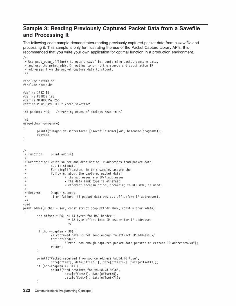
Sample 3: Reading Previously Captured Packet Data from a Savefile
and Processing It
The following code sample demonstrates reading previously captured packet data from a savefile and
processing it. This sample is only for illustrating the use of the Packet Capture Library APIs. It is
recommended that you write your own application for optimal function in a production environment.
/*
* Use pcap_open_offline() to open a savefile, containing packet capture data,
* and use the print_addrs() routine to print the source and destination IP
* addresses from the packet capture data to stdout.
*/
#include <stdio.h>
#include <pcap.h>
#define IFSZ 16
#define FLTRSZ 120
#define MAXHOSTSZ 256
#define PCAP_SAVEFILE "./pcap_savefile"
int packets = 0; /* running count of packets read in */
int
usage(char *progname)
{
printf("Usage: %s <interface> [<savefile name>]\n", basename(progname));
exit(7);
}
/*
* Function: print_addrs()
*
* Description: Write source and destination IP addresses from packet data
* out to stdout.
* For simplification, in this sample, assume the
* following about the captured packet data:
* - the addresses are IPv4 addresses
* - the data link type is ethernet
* - ethernet encapsulation, according to RFC 894, is used.
*
* Return: 0 upon success
* -1 on failure (if packet data was cut off before IP addresses).
*/
void
print_addrs(u_char *user, const struct pcap_pkthdr *hdr, const u_char *data)
{
int offset = 26; /* 14 bytes for MAC header +
* 12 byte offset into IP header for IP addresses
*/
if (hdr->caplen < 30) {
/* captured data is not long enough to extract IP address */
fprintf(stderr,
"Error: not enough captured packet data present to extract IP addresses.\n");
return;
}
printf("Packet received from source address %d.%d.%d.%d\n",
data[offset], data[offset+1], data[offset+2], data[offset+3]);
if (hdr->caplen >= 34) {
printf("and destined for %d.%d.%d.%d\n",
data[offset+4], data[offset+5],
data[offset+6], data[offset+7]);
}
322 Communications Programming Concepts
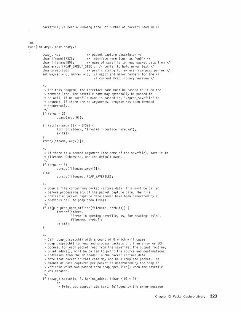
packets++; /* keep a running total of number of packets read in */
}
int
main(int argc, char **argv)
{
pcap_t *p; /* packet capture descriptor */
char ifname[IFSZ]; /* interface name (such as "en0") */
char filename[80]; /* name of savefile to read packet data from */
char errbuf[PCAP_ERRBUF_SIZE]; /* buffer to hold error text */
char prestr[80]; /* prefix string for errors from pcap_perror */
int majver = 0, minver = 0; /* major and minor numbers for the */
/* current Pcap library version */
/*
* For this program, the interface name must be passed to it on the
* command line. The savefile name may optionally be passed in
* as well. If no savefile name is passed in, "./pcap_savefile" is
* assumed. If there are no arguments, program has been invoked
* incorrectly.
*/
if (argc < 2)
usage(argv[0]);
if (strlen(argv[1]) > IFSZ) {
fprintf(stderr, "Invalid interface name.\n");
exit(1);
}
strcpy(ifname, argv[1]);
/*
* If there is a second argument (the name of the savefile), save it in
* filename. Otherwise, use the default name.
*/
if (argc >= 3)
strcpy(filename,argv[2]);
else
strcpy(filename, PCAP_SAVEFILE);
/*
* Open a file containing packet capture data. This must be called
* before processing any of the packet capture data. The file
* containing pcaket capture data should have been generated by a
* previous call to pcap_open_live().
*/
if (!(p = pcap_open_offline(filename, errbuf))) {
fprintf(stderr,
"Error in opening savefile, %s, for reading: %s\n",
filename, errbuf);
exit(2);
}
/*
* Call pcap_dispatch() with a count of 0 which will cause
* pcap_dispatch() to read and process packets until an error or EOF
* occurs. For each packet read from the savefile, the output routine,
* print_addrs(), will be called to print the source and destinations
* addresses from the IP header in the packet capture data.
* Note that packet in this case may not be a complete packet. The
* amount of data captured per packet is determined by the snaplen
* variable which was passed into pcap_open_live() when the savefile
* was created.
*/
if (pcap_dispatch(p, 0, &print_addrs, (char *)0) < 0) {
/*
* Print out appropriate text, followed by the error message
Chapter 12. Packet Capture Library 323
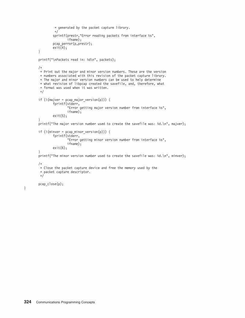
* generated by the packet capture library.
*/
sprintf(prestr,"Error reading packets from interface %s",
ifname);
pcap_perror(p,prestr);
exit(4);
}
printf("\nPackets read in: %d\n", packets);
/*
* Print out the major and minor version numbers. These are the version
* numbers associated with this revision of the packet capture library.
* The major and minor version numbers can be used to help determine
* what revision of libpcap created the savefile, and, therefore, what
* format was used when it was written.
*/
if (!(majver = pcap_major_version(p))) {
fprintf(stderr,
"Error getting major version number from interface %s",
ifname);
exit(5);
}
printf("The major version number used to create the savefile was: %d.\n", majver);
if (!(minver = pcap_minor_version(p))) {
fprintf(stderr,
"Error getting minor version number from interface %s",
ifname);
exit(6);
}
printf("The minor version number used to create the savefile was: %d.\n", minver);
/*
* Close the packet capture device and free the memory used by the
* packet capture descriptor.
*/
pcap_close(p);
}
324 Communications Programming Concepts
Index
Aaddresses
binding 204
NDD 199
obtaining 205
Socketdata structures 195
families 196
storage 198
TCP/IP 198
translation 212, 216
agent (SNMP) 125
array data type (XDR) 89
arraysXDR 106
XDR filter primitive 97
authentication 138
DESRPC 140, 168
NULL (RPC) 139
UNIX (RPC) 139, 166
Bbatching (RPC) 153
bindingSockets 203, 204
binding processes (RPC) 133
booleandata type (XDR) 86
RPC 86
booleansRPC 159
broadcasting (RPC) 154, 177
server side 161
byte-order translation 216
CC preprocessor (RPC) 161
callbackRPC 180
callback proceduresRPC 154
canonical data representation (XDR) 80
client routines 109
clientsagent 110, 112
binding 133
clocks 141
communications domains (Sockets) 196
connections (Sockets) 205
constantsRPC language 157
XDR language 92
conversion routines 110
Ddata description 102
data link control 2
data representationcanonical 80
data streams (XDR) 98
data structures 312
data transfer, (Sockets) 208
data typespassing 175
data types (XDR) 84
databaseMIB 123
database manager 77
datagram servicesconnectionless 207
DBMNDBM equivalents 78
subroutines 78
DCL8023 (IEEE 802.3 Ethernet data link control) 24
declarationsRPC language 158
XDR language 83
DESauthentication
RPC 143, 168
DES authenticationprotocol 142
RPC 140
Diffie-Hellman encryption 143
discriminated unionexample 91
discriminated union (XDR)example 107
XDR 91
DLC (data link control) 12, 24, 34, 44
device manager environmentcomponents 3
multiuser configuration 3
structure 2
error logging facility 9
generic 2
programming procedures 11
qualified logical link control 51
reference information 11
DLC_ENABLE_SAP 21
DLC8023programming interfaces 31
protocol support 26
data packet 26
response modes 26
station types 26
DLC8023 (IEEE 802.3 Ethernet data link control)connection contention 30
direct network services 30
link sessionsinitializing 30
© Copyright IBM Corp. 1994, 2005 327
DLC8023 (IEEE 802.3 Ethernet data link control)
(continued)link sessions (continued)
terminating 31
name-discovery services 27
overview 24
DLC8023 device managerfunctions 25
nodes 25
DLCETHER (standard Ethernet data link control) 34
connection contention 40
device manager functions 35
device manager nodes 35
direct network services 40
link sessionsinitiating 40
terminating 41
name-discovery services 37
overview 34
programming interfaces 41
protocol support 36
DLCQLLC device manager 51
DLCTOKENdevice manager
ADM and ABME modes 13
functions of 14
introduction 12
DLCTOKEN (token-ring data link control) 12
connection contention 19
device manager functions 14
device manager nodes 13
direct network services 19
initiating link sessions 19
name-discovery services 16
programming interfaces 20
protocol supportdata packet 15
response modes 15
station types 15
driversconfiguring, in PSE 277
STREAMS 273
Eenumeration data type (XDR) 86
enumerationsRPC language 157
XDR language 83
error loggingSMUX example subroutines 128
exampleXDR 105
eXternal Data Representation 79
FFDDIDLC
connection contention 63
device manager functions 58
device manager nodes 58
FDDIDLC (continued)device protocol support 59
direct network services 63
initiating link sessions 63
name-discovery services 60
programming interfaces 64
Fiber Distributed Data Interface 57
filter expressions 313
filter primitivesbasic 95
constructed 96
floating-point data types (XDR) 86
Flow Control, STREAMS 254
GGDLC
overview 2
GDLC (generic data link control)criteria 4
interfaceimplementing 4
ioctl operations 5
kernel services 7
problem determinationerror logs 9
LAN monitor trace 10
link station trace 10
overview 8
status information 8
generic data link control 2
Hhandles
RPC 163, 164
header files 312
Sockets 195, 248
highest layerRPC 149
II/O modes
sockets 210
idsocket 208
include filesSockets 195
integer data type (XDR) 85
interface (Sockets) 193, 194
intermediate layer 149
RPC 170
internet protocolmulticasts 211
intrinsic functionslist of 127
ioctl operationsSockets 202
STREAMS 265
328 Communications Programming Concepts
LLAN
monitor trace 10
language (RPC) 155
language specifications (XDR) 82
librariesRPC run-time 109
XDR 81, 94
librarySockets 194
XDR 95
link station 6
linked lists (XDR) 100
linkstesting 7
tracing 7
LLC 13, 14
local-busy mode 7
location brokerclient agent 110, 112
components 110
daemons 110
global 113
local 113
overview 110
log device driver 275, 276
lowest layerRPC 151
LSdefinition 6
statisticsquerying 7
LS (link station)trace facilities
channels 10
trace facilityentries 10
entry size 10
reports 10
using with DLCTOKEN 19, 20
MMAC 14
Management Information Base 120
memoryallocating 152
message, sending 211
messagesblocks 268
RPC 138
streams 268
MIBdatabase 123
overview 120
variables 122, 123
model (RPC) 132
modules 267
64-bit support 274
configuring (PSE) 277
modules (continued)introduction to streams 251
modules 274
user-context 273
monitorsSNMP 125
multiprogram versionsRPC 176
NNCS 109
NDBMDBM equivalents 77
subroutines 77
NDDprotocols 199
socket addresses 199
NDMBproblem diagnosis 77
Network Computing System 109
Network Information Service 115
Network ManagementSNMP 119
xgmon 119
NISfiles 115
subroutines 115
non-filter primitiveslist 98
nonfilter primitiveslist 94
Oopaque data type
RPC 160
opaque data typesXDR 88
optional data types (XDR) 93
options, socket 208
options, sockets 208
out-of-band data 209
Ppacket capture library 311
data structures 312
delayed processing ex. 318
filter expressions 313
header files 312
print binary form ex. 315
savefile ex. 322
subroutines 312
passing linked lists (XDR)example 100
ping program (RPC) 183
pointersXDR 108
port mapper 144
Portable Streams Environment 277
Index 329
portsregistering (RPC) 144
primitivesfilter 95
non-filter 98
nonfilter 94
procedurepacket capture 311
procedure numberslist of 148
procedure numbers (RPC)assigning 148
program numbersassigning (RPC) 147
protocolRPC
port mapper 145
Sockets 202, 248
protocol compilersrpcgen 160
protocolsRPC 133
authentication 138
specifications 148
PSE 277
put proceduresStreams 271
QQLLC (qualified logical link control) DLC
describing device manager functions 52
QLLC (Qualified Logical Link Control) DLCdescribing programming interfaces 52
device manager 51
overview 51
qualified logical link control 51
QUEUESprocessing messages with STREAMS 271
Rrecords
RPC messages 138
Remote Procedure Call (RPC)highest layer 149
lowest layer 151
remote procedure calls 109, 131
RPCarbitrary data types
passing 175
authentication 138
client side 139
DES overview 140
DES protocol 142
server side 140
batching 153
binding process 133
broadcasting 177
protocols 154
server side 161
RPC (continued)C preprocessor 161
callback 180
procedures 154
constants 157
converting local procedures 184
overview 160
declarations 158
enumerations 157
exampleslist of 162
features 153
generating XDR routines 187
overview 161
intermediate layer 170
language 155
macros 162
message protocol 133
message replies 136
messages 134
model 132
multiple program versions 176
overview 131
port mapper 144
programming 146
programslist of 148
rpc process (TCP) 178
rpcgen protocol compiler 160
select subroutine 178
on the server side 155
semantics 133
server procedures 162
startingfrom inetd daemon 153
structures 156
subroutines 162
timeoutschanging 161
transports 133
type definitions 157
unions 156
XDR, using with 82
RPC (Remote Procedure Call)arbitrary data types
passing 151
intermediate layer 149
marking records in messages 138
RPC authenticationDES 168
clock synchronization 141
Diffie-Hellman encryption 143
naming scheme 140
nicknames 141
on the client side 141
on the server side 141
verifiers 141
NULL 139
overview 138
protocol 138
UNIX 166
330 Communications Programming Concepts
RPC authentication (continued)overview 139
RPC example programsgenerating XDR routines 187
ping program 183
select subroutine 178
UNIX authentication 166
RPC languageconstants 157
declarations 158
definitions 155
descriptions 155
enumerations 157
exceptions to rulesbooleans 159
opaque data 160
strings 159
voids 160
overview 155
ping program 183
programssyntax 157
rpcgen protocol compiler 160
structures 156
syntax requirements for program definition 159
type definitions 157
unions 156
RPC layershighest 170
intermediatehandling arbitrary data structures 149
routines 149
lowest 171
RPC messagescalls 134
protocol requirements 134
replies 136
structures 134
RPC port mapperoverview 144
procedures 146
protocol 145
registering ports with 144
rpc process (RPC)on TCP 178
RPC programmingprocedure numbers 148
program numbers 147
version numbers 147
RPC programscompiling 153
linking 153
list of 148
syntax 157
RPC runtime libraryNCS 109
routinesclient 109
conversion 110
server 109
rpcgen protocol compilerbroadcasting
server side 161
C preprocessor 161
changing timeouts 161
converting local procedures 160, 184
generating XDR routines 161, 187
other information passed to server 162
overview 160
RPCL 159
SSAP
definition 6
statisticsquerying 7
SDLC 44
SDLC (synchronous data link control) DLCdevice manager functions 45
programming interfaces 48
providing protocol support 45
SDLC (Synchronous Data Link Control) DLCinitiating asynchronous function subroutine calls 51
select subroutines (RPC) 178
overview 155
semantics (RPC) 133
sending messages 211
server procedures (RPC) 162
serversRPC routines and 109
service access point 6
service proceduresSTREAMS 272
short-hold mode 7
shutdown sockets 210
simple network management protocol 119
SMUX subroutines 127
adios 128
advise 129
SNMPagent 125
database 120
monitor 125
overview 119
traps 126
SNMP multiplexer (SMUX) 128
socketbinding 198
communication domains 196
sockets 198
accepting internet Streams connections 223
accepting UNIX Stream connections 226
address translation 212
atm socket pvc clientsending data 227
atm socket pvc serverreceiving data 228
atm socket rate-enforced svc serverreceiving data 233
Index 331

sockets (continued)atm socket svc client
sending data 235
atm socket svc serverreceiving data 238
atm sockets rate-enforced svc clientsending data 229
binding addresses 204
binding names 203
blocking mode 210
checking pending connections 224
closing 210
connecting 192
connectionless 207
connections 205
creating 192, 203
data structures 195
data transfer 193, 208
ethernetreceiving packets 241
sending packets 243
examples, understanding 218
header files 195, 248
I/O modes 210
interface 193, 194
internet datagramsreading 219
sending 220
Internet Streaminitiating 222
kernel serviceslist of 246
layer 193
library 194
subroutines 247
namesbinding 203
host 215
network 215
protocol 215
resolution 216
service 215
translation 216
network packetsanalyzing 245
out-of-band data 209
protocols 202, 248
server connections 206
shutdown 210
socketpair subroutine 219
types 201
UNIX datagramsreading 221
sending 221
UNIX Stream connections 225
XDR 105
Socketsoptions, get, set 208
overview 191
standard Ethernet data link control 34
statisticsquerying
LS 7
SAP 7
stream end 252
stream head 250
streamsTLI 289
STREAMSasynchronous protocol example 280
building 265
commands 286
configuring 286
maintaining 287
definition 249
differences between PSE and V.4 285
driversintroduction 273
list of 287
Flow Control 254
functionslist of 288
ioctl operations 263
log device driver 275, 276
message queue 270
messages 268
allocation 269
sending and receiving 271
types 269
modules 251, 253, 273
list of 287
overview 249
protocol substitution 253
PSE 277
pushable modules 267
put procedures 271
QUEUE procedures 271
queues 270
service procedures 272
stream end 252
stream head 250
streamio operations 265
subroutines 262
list of 287
synchronization 255
system calls 262
list of 288
tunable parameters 263
understanding flow control 254
utilitieslist of 288
welding mechanism 261
stringsRPC 159
XDR 90
structuresRPC language 156
XDR language 83, 91
subroutine format (XDR) 81
subroutines 312
Synchronous Data Link Control 44
332 Communications Programming Concepts
TTCP/IP
list of RFCs 308
programming referenceslist of files and file formats 307
list of methods 307
socket addresses 198
timeoutschanging (RPC) 161
token-ring data link control 12
Transmission Control Protocol/Internet Protocol 293
transport protocoland RPC 133
transport service library interface 289
traps 126
type definitionsRPC language 157
XDR language 92
UUnderstanding STREAMS Flow Control 254
unionsdiscriminated 91
optional data 93
RPC language 156
XDR language 83
UNIX authentication (RPC) 139, 166
VV.4 STREAMS
differences between and 285
version numbersassigning (RPC) 147
voidsRPC 160
XDR 92
XXDR
canonical data representation 80
data streams 98
data types 84
filter primitives 95, 96
generating routines with RPC 161
languagespecifications 82
library 81
memory allocation (RPC) 152
non-filter primitives 98
overview 79
primitives 95
programming reference library 94
remote procedure calls and 131
RPCgenerating routines with 187
RPC, using with 82
structures 91
XDR (continued)subroutine format 81
type definitions 92
unionsoptional data 93
unsupported representations 81
using rpc process with 178
XDR (eXternal Data Representation)unions
discriminated 91
XDR examplearray 106
data description 102
discriminated unions 107
justification for using 103
linked lists 100
pointers 108
XDR languageblock size 80
declarations 83
enumerations 83
lexical notes 82
structures 83
syntax notes 84
unions 83
XTI 289
Index 333

334 Communications Programming Concepts

Vos remarques sur ce document / Technical publication remark form
Titre / Title : Bull AIX 5L Communications Programming Concepts
Nº Reférence / Reference Nº : 86 A2 69EM 02 Daté / Dated : October 2005
ERREURS DETECTEES / ERRORS IN PUBLICATION
AMELIORATIONS SUGGEREES / SUGGESTIONS FOR IMPROVEMENT TO PUBLICATION
Vos remarques et suggestions seront examinées attentivement.
Si vous désirez une réponse écrite, veuillez indiquer ci-après votre adresse postale complète.
Your comments will be promptly investigated by qualified technical personnel and action will be taken as required.
If you require a written reply, please furnish your complete mailing address below.
NOM / NAME : Date :
SOCIETE / COMPANY :
ADRESSE / ADDRESS :
Remettez cet imprimé à un responsable BULL ou envoyez-le directement à :
Please give this technical publication remark form to your BULL representative or mail to:
BULL CEDOC
357 AVENUE PATTON
B.P.20845
49008 ANGERS CEDEX 01
FRANCE
Technical Publications Ordering Form
Bon de Commande de Documents Techniques
To order additional publications, please fill up a copy of this form and send it via mail to:
Pour commander des documents techniques, remplissez une copie de ce formulaire et envoyez-la à :
BULL CEDOCATTN / Mr. L. CHERUBIN357 AVENUE PATTONB.P.2084549008 ANGERS CEDEX 01FRANCE
Phone / Téléphone : +33 (0) 2 41 73 63 96FAX / Télécopie +33 (0) 2 41 73 60 19E–Mail / Courrier Electronique : [email protected]
Or visit our web sites at: / Ou visitez nos sites web à:
http://www.logistics.bull.net/cedoc
http://www–frec.bull.com http://www.bull.com
CEDOC Reference #No Référence CEDOC
QtyQté
CEDOC Reference #No Référence CEDOC
QtyQté
CEDOC Reference #No Référence CEDOC
QtyQté
_ _ _ _ _ _ _ _ _ [ _ _ ] _ _ _ _ _ _ _ _ _ [ _ _ ] _ _ _ _ _ _ _ _ _ [ _ _ ]
_ _ _ _ _ _ _ _ _ [ _ _ ] _ _ _ _ _ _ _ _ _ [ _ _ ] _ _ _ _ _ _ _ _ _ [ _ _ ]
_ _ _ _ _ _ _ _ _ [ _ _ ] _ _ _ _ _ _ _ _ _ [ _ _ ] _ _ _ _ _ _ _ _ _ [ _ _ ]
_ _ _ _ _ _ _ _ _ [ _ _ ] _ _ _ _ _ _ _ _ _ [ _ _ ] _ _ _ _ _ _ _ _ _ [ _ _ ]
_ _ _ _ _ _ _ _ _ [ _ _ ] _ _ _ _ _ _ _ _ _ [ _ _ ] _ _ _ _ _ _ _ _ _ [ _ _ ]
_ _ _ _ _ _ _ _ _ [ _ _ ] _ _ _ _ _ _ _ _ _ [ _ _ ] _ _ _ _ _ _ _ _ _ [ _ _ ]
_ _ _ _ _ _ _ _ _ [ _ _ ] _ _ _ _ _ _ _ _ _ [ _ _ ] _ _ _ _ _ _ _ _ _ [ _ _ ]
[ _ _ ] : no revision number means latest revision / pas de numéro de révision signifie révision la plus récente
NOM / NAME : Date :
SOCIETE / COMPANY :
ADRESSE / ADDRESS :
PHONE / TELEPHONE : FAX :
E–MAIL :
For Bull Subsidiaries / Pour les Filiales Bull :
Identification:
For Bull Affiliated Customers / Pour les Clients Affiliés Bull :
Customer Code / Code Client :
For Bull Internal Customers / Pour les Clients Internes Bull :
Budgetary Section / Section Budgétaire :
For Others / Pour les Autres :
Please ask your Bull representative. / Merci de demander à votre contact Bull.


BULL CEDOC
357 AVENUE PATTON
B.P.20845
49008 ANGERS CEDEX 01
FRANCE
86 A2 69EM 02
ORDER REFERENCE