Embed Size (px)
Citation preview
AD-AI00 135 ROYAL AIRCRAFT ESTABLISHMENT FARNBOROUbH (ENGLAND) F/b 20/4SOME MEMARKS ON BUFFETINGtU
FEB Al 0 6 MABEY
UNCLASSIFIED RAE-TM-SIRUCTURES-98U ORIC- BR 78b30 N

- . -
ROYAL AIRCRAFT ESTABLISHMEN
i.m
SOWE ME~AW ON BUFTING e-
by
_1<,
1 6D. 0 . 2.
UNLIMITED816 03 0 .
ROYAL AIRCRAFT ESTABLISHMENT
Technical Memorandum Structures 980
Received for printing 5 February 1983
SOME REMARKS ON BUFFETING
by
D. G. Mabey
" SU~MRY
Buffeting is defined as the structural response to the aerodynamic excita-
tion produced by separated flows. The aerodynamic excitation produced by bubbles,
vortices and transonic flows is discussed.
Different buffeting criteria for the wings of fighter and transport aircraft
are developed. Methods of predicting the onset and severity of buffeting are
reviewed. Some typical examples are discussed, in which improvements in wing
buffeting are compared with changes in mean force measurements.
The first buffeting measurements on ordinary models in a cryogenic wind
wind tunnel are analysed. The measurements confirm that cryogenic tunnels can
separate Reynolds number and aeroelastic effects. The frequency parameter must
be correct on the model if the aerodynamic excitation does not have a flat spec-
trum, as at vortex breakdown on a slender wing.
The violent periodic flows at transonic speeds recently observed on thick
biconvex aerofoils are briefly reviewed and compared with solutions of the full
Navier-Stokes equations.
I
This paper was prepared for the YKI lecture series "Unsteady airloads andaeroelastic problems in separated and transonic flows", to be given on10 March, 1981 in Brussels.
Copyright©
Controller HMSO London(1981
-- *,. .~*.;7-7L
2
LIST OF CONTENTS
NOTATION 3
I INTRODUCTION 3
2 CLASSIFICATTON OF WING FLOWS AND BUFFETING 4
3 EXPERIMENTAL METHODS 8
4 THEORETICAL METHODS 14
5 CONCLUSIONS 14
References 14
Illustrations Figures 1-35
Report documentation page inside back cover
Accesslon ForNTIS Gr c' l
DTIC
Di:t '
J11
tI
0
NOTATION
c wing chord (m) 1n frequency parameter fL/V
SB - CB(M,) buffeting coefficient - wing root p pressure fluctuation in a bandstrain signal/kinetic pressure Af at frequency f (N/M
2)
(arbitrary units)rms pressure fluctuations (N/m
2)
CB , CB" dimensionless buffetingcoefficients defined in 7/q
2 . log n- nF(n)d(log n)
Equation (3) and (4) log n--
CL lift coefficient q kinetic pressure IPV2
(N/rn2)
f frequency (Hz) R Reynolds number - based on
F(n) contribution to p-/q2 in aerodynamic mean chord
frequency band An V free stream velocity (m/s)
A-F 7n p/q(e)1/2 x distance from leading-edge (m)Ktransformation factor atc °
Equation (3) a angle of incidence or angle ofEquatin (3)attack (0)
L typical dimension e analyser bandwidth ratio (U/f)
bubble length (m) sweep angle (o)
p free stream density (kg/m3)
I INTRODUCTION
We must first establish what we mean by buffeting. Buffeting is defined as the structural response
to the aerodynamic excitation produced by separated flow. In the example sketched in Figure 1, there isa large area of separated flow on the wing. This provides the excitation which at a given point may be
characterised by the -ms level, the frequency spectrum (we shall see that the spectrum is often fairlyflat at low frequencies), the degree of correlation in space and time, and the length scale. The pressure
fluctuations excite a response of the structural modes which we call buffeting. The aircraft structureacts as a selective filter for the excitation so that spectra of buffeting always contain pronounced peaks
at structural frequencies. In the example sketched in Figure I both the wing and the tpilAsne are excited.Rigid body modes may also be excited, such as "wing rocking", "wing dropping" or "nose slicing", but theseare at much lower frequencies and can be regarded as aircraft handling problems, of great importance but
outside the scope of this lecture. Buffet onset is often defined as the first appearance of a significant
area of separated flow, although aerodynamicists often argue about how large the area must become before itis significant. (This is one of the uncertainties inherent in the theoretical methods for the prediction
of buffet onset now being developed.) The onset of buffeting in flight is even more difficult to specify,for much of our present data are based on pilot impressions, which may be inaccurate if the pilot sits onor close to a node of the predominant modes being excited. Most pilots expect wing buffeting to provide awarning of more serious phenomena such as stall, pitch up or wing-drop, and are unhappy with aircraft whichdo not provide such a warning, unless an automatic visual or audio warning system is fitted.
The term buffeting was apparently first introduced into aeronautical literature when a structural* failure occurred to the tail of a Junkers monoplane in 1930 (Ref 1). This failure was attributed by the
British accident investigation to buffeting of the tailplane excited by flow separations on the wing.The flow separations on the wing were caused by an encounter with a severe gust and the German investiga-
*tion attributed the accident directly to the structural failure of the wing caused by the gust (Ref 2).
This incident emphasises again that buffeting often occurs in critical flight situations, when limit loadsare being approached or when the aircraft is approaching lateral or longitudinal stability boundaries.(These early report even include some discussion of the importance of correctly representing the aircraft
o geometry on the model and of the problems posed by testing at low Reynolds numbers. These issues are stillo0 important today.)
A consistent, diicns ionless representation of exc itation spectra is required when comparin "leasure-
ments made at different flow densities and velocities. We shall adopt the notation suggested by ' B Owen(Ref 3) and represented in Figure 2. Here we have a frequency parameter
n - fL/V
and an excitation level
p/q/c - /nF(n)
Buffeting Criteria for Fighter and Transport Aircraft
Figure 3 illustrates how buffeting criteria, expressed in terms of CL - M boundaries, can influencethe choice of wing loading for fighter and transport type aircraft. The boundaries presented for onset,light, moderate and heavy buffeting are based on some unpublished RAE measurements (Ref 4). (Theseboundaries are derived by a method outlined later.)
A typical fighter aircraft (with a wing leading-edge of sweep angle 420) will cruise well below thebuffet onset boundary, but will frequently perform 5g manoeuvres which take it well beyond the buffetboundary to the moderate buffeting, or even to the heavy buffeting contour. For a fighter aircraft themoderate buffeting limit is sometimes taken as the highest level at which guns or missiles can be aimedsuccessfully, whereas the heavy buffeting limit is that at which the aircraft becomes useless as aweapon platform, but is still controllable. For a fighter, frequent buffeting loads can seriouslyinfluence the fatigue life of the structure, for thej are considerably larger than the loads caused byturbulence. The influence of the buffeting loads un the fatigue life of the new generation of advancedcombat aircraft will need careful consideration. These aircraft can manoeuvre at higher lift coefficientsandkinetic pressures than previous aircraft, without encountering rigid body modes such as wing droppingor nose slicing, because the separations are well controlled. However the pilot could be largely unawareof high frequency responses occurring in structural modes which could strongly influence the life of theairframe.
In contrast a typical transport aircraft (with the wing leading-edge of sweep angle 270) may cruiseat about 0.1 in C below the buffet onset boundary. On infrequent occasions the aircraft may encountera strong gust whi~ch carries the aircraft beyond the buffet boundary, right up to the moderate buffetinglevel. (The gust of 12.5 m/s selected in this example would have a wavelength of about 33 m (Ref 5)). Thesteady load achieved during the excursion into buffeting is probably more serious than the buffeting loads,which may be little larger than those associated with the atmospheric turbulence encountered during everyflight.
Buffeting on fighter and transport aircraft only determines the extent of the penetration beyondthe buffet boundary if there are no other handling limitations, such as wing rocking, wing dropping,pitch-up or stalling. We will return to this point later.
2 CLASSIFICATION OF WING FLOWS AND BUFFETING
A broad classification of wings with separated flows that excite buffeting will be useful as aframework for our discussion, even if the classification suggested is incomplete (Fig 4).
Wings with low angles of sweep are characterised beyond the buffet boundary at subsonic speeds byleading-edge or trailing-edge separations. These separations form bubbles on the wing which usuallyexcite heavy buffeting. At transonic speeds the presence of strong shock waves nearly parallel with theleading-edge add to the difficulties of predicting the flow, so that we give this flow a predictionrating of 10. (These prediction ratings are arbitrary and not used in any calculations; an increase inprediction rating represents increased difficulty of prediction.) Swept wings are characterised by acombination of mixed flows (Ref 6) which are difficult to predict. The separated flows on a swept wingat transonic speeds may include shock waves (which vary in intensity across the span), bubbles (from theleading-edge or the trailing-edge) and vortices. Thus a small increase in Mach number may dramaticallyalter the position of a shock wave or the reattachment point of a bubble. Similarly an increase in unitReynolds number or a change of the roughness band used to fix transition on the model in wind tunnel testsmay completely alter the character of the shock wave/boundary layer interation (References 7 and 8).These difficulties seem to justify a prediction rating for swept wings of 100; an even higher ratingwould be appropriate for a variable geometry wing.
Slender wings with sharp leading-edges are characterised by a simple vortex type of flow, whichprevails over the complete speed range from subsonic to supersonic speeds. This unified type of flow isa powerful argument for the application for supersonic aircraft (Ref 9). The vortices, which producesignificant non-linear lift, have a well defined, small scale structure and we shall see that they do notproduce severe buffeting unless vortex breakdown occurs at high angles of attack outside the normal flightenvelope. In addition the vortices on slender wings with sharp leading-edges are relatively insensitiveto wide variations in Reynolds number. Hence slender wings are given a prediction rating of 1.
These prediction ratings are, or course, arbitrary, but they reflect real differences between theflows, which are now considered in greater detail.
Unswept Wings
The character of the excitation cauL-d by leading-edge separation bubbles on unswept wings may be 't
inferred (Ref 10) from the simplified model tic a bubble suggested by Norbury and Crabtree in Reference11 (Fig 5). In the constant-pressure region of the bubble, we would expect the excitation caused by lowfrequency fluctuations in the separation point to be relatively small, whereas in the reattachient rt gion, owhere the rate of pressure recovery is high, the excitation should be much higher. Thus the excitationmight be expected to reach a maximum in the middle of the reattachmcnt region. These inferences from themean static pressure distributions are broadly confirmed by the measurements, althought the excitationattenuates both upstream and downstream of the reattachment region owing to the influence of the shearlayer.
The spectrum of surface pressure fluctuations for a boundary layer approaching separation in anadverse pressure gradient may be divided into high-frequency and low-frequency components (Ref 12). Thehigh-frequency pressure fluctuations are similar to those found under a boundary layer in zero pressuregradient (Ref 13) and are generated in the small scale iner region of the boundary layer associated withthe law of the wall. The low-frequency pressure fluctuations are generated in the large-scale outer region
€5
associated with the law of the wake, and increase in intensity as the outer region of the boundary layerthickens.. Between separation and reattachlincut. measurements suggest that the low-frequency pressurefluctuations continue to increase steadily as the separated boundary layer thickens, until a point isreached where the mixing layer turns towards the surface and the mean pressure starts to increase.(Bradshaw has shown that the flow in the reattaciaenr region is dominated by a rapid reduction in eddysize as the shear layer is divided into two halves. The lower half of the shear layer moves upstreamf=rs reattachment; the upper half moves downstream (Ref 14). It seems reasonable that this suddenreduction in eddy size should be accompanied by a sudden reduction in excitation at low frequencies.)Somewhere close to the reattachment point, the measurements for a wide range of bubble flows show amaximum value of the rms pressure fluctuation coefficient of
p/q between 0.10 and 0.04
The spectra also show a marked similarity if the frequency parameter n is based on the bubble length I,for a peak pressure fluctuation is found when
n - fl/V - 0.5 to 0.8 (I)
This prcoably implies a feed-back process between conditions at the reattachment and separation points.Equation (1) will be inappropriate when there is a strong, coherent disturbance in the wake (eg a Klrmanvortex street) of if there re acoustic resonances (as there may be in cavities). The measured pressurefluctuations always cover a broad band of low frequencies, rather than a single discrete frequency asgiven by Equation (I), probably because the velocity of the eddies in the shear layer varies with theeddy size.
Leading-edge bubbles may be important for a*rcraft with sharp leading-edges, for which we havesome good excitation measurements (Fig 6). Leading-edge bubbles were formed on the centre section of theBristol 188 aircraft (Ref 15) and on a Venom aircraft with a sharp leading-edge (Ref 16). Figure 6 showsthat the rms excitation at two points on the Bristol 188 increases gradually from separation (x/l - 0),reaches a maximum zf
p/q - 0.10
just upstream of the reattachment point (x/l = 1.00),and then decreases. The frequency parameter n basedon the bubble length has a maximum at about n - 0.7 and correlates the spectra quite well at x/c - 0.85,where moat of the measurements are taken in the region of rapid pressure recovery (x/l - 0.94). The peaklevel is about /nF(n) - 0.006. (The parameter n does not work so well at x/c - 0.50, where some of themeasurements are taken in the constant steady pressure re-ion (x/1 - 0.56). Measurements of pressurefluctuations on a Venom aircraft also conform to the general pattern shown in Figure 6(a) and show nosignificant variation in the rms pressure fluctuations or the spectra over the Mach number range fromM - 0.3 to 0.6. Only a small Reynolds number effect on the low-speed pressure fluctuations was measuredbetween the aircraft and a model (Ref 16). Some pressure fluctuation measurements on aerofoils with roundleading edges (Re, 17) suggest similar rms levels and a peak frequency parameter of about 0.8 to 1.0.
Equation (1) helps us tj discriminate between the excitation frequencies associated with long andshort bubbles uccause of the large changE in the bubble length between the two flows. A long bubble coversa significant area of the aerofoil chord and, from Reference 18, because
1/c - 0(1)
the pressure fluctuations will be at comparatively low frequencies which can excite the structural modes;eg for a long bubble on a wing with a chord of 3 m moving it 70 mis, the excitation frequency would be
0 (12 Hz)
(Typical wing fundamental bending frequencies are 10 Hz for a small aeroplane and 2 Hz for a large aero-plane.) A short bubble only influences a small area of the wing, but, in addition, because
l/c - 0(0.01)
these pressure fluctuations will be at such high frequencies that they are unl~kely to excite structuralmodes; eg for a short bubble on a wing with 3 m chord moving at 70 m/s, the e,itation frequency would be
0 (1200 Hz)
Flight tests on the Venom with a sharp leading-edge (Ref 16), and the canard control of the XB-70(Ref 19), showed that buffet onset corresponded with the formation of a long bubble. The butLUi~ng thenincreased steadily as the bubble extended downstream, until the reattachment point approached the trailing-
o edge and the trailing-edge pressure diverged. This point corresponded with heavy buffeting. Hence the00 local pressure fluctuations within a long bubble must be quite strongly correlated.ON
"i # The character of the excitation caused by 4 spoiler of height h (Fig 6(b)) closely resembles thatcaused by a leading-edge bubble. The excitation increases steadily from separation and reaches a maximumof
p/q - 0.0!
just upstream of reattachment. The peak frequency parameter n tor the spoilei is about 0,9 in che experi-ments of Fricke, rather than 0.7 for the leading-edge bubble. The experimeots of Fricke (Ref 20), in air,and of Creshilov (Ref 21), in water, give peak frequency paiameters of about 0.9 and 0.8 althoughthebubble lengths are respectively 16 h and 5.5 h. The coincidence of the frequency parameters based on
- - . -w- i
bubble length confirms that this is a useful parameter for comparing the spectra of the pressure fluctua-tions generated by bubble flows.
The character of the rms pressure fluctuations and spectra caused by bubbles is largely indepen-dent of the origin of the bubble (Ref 10). Thus, in particular, the maximum pressure fluctuations occurjust upstream of reattachment for:
- leading-edge bubbles,- bubbles downstream of spoilers,- bubbles downstream of steps,- bubbles upstream of steps,- bubbles downstream of sudden expansion in pipes,- bubbles within shallc cavities (Fig 7).
Thus the data correlations presented in Reference 10 have application to a wide class of flows.
The prediction of the onset and severity of buffeting is of crucial important at transonic speeds.In this speed range, the mixed subsonic/supersonic flows and the different regimes of shock/boundary layerinteraction can modify the model for bubble flows described here, at least near the shock. However, down-stream of the shock, an approximately constant average pressure is often observed in the separated flowregion, followed by a rapid rise to reattarhwent. Coe's investigation (Ref 22) of the loads on launchvehicles included some measurements at oubsonic and transonic speeds of the mean and fluctuating staticpressures caused by a separation bubble downstream of a step in a body of revolution (Fig 8). Both themean and fluctuating pressure distributions aft of the step correspond very well in general character withthe low-speed pressure distributions over the complete speed range from M - 0.60 to 1.19, although the maxi-mum fluctuating pressure falls steadily from
p/q - 0.06 at M - 0.80
to
p/q - 0.03 at M - 1.19
This fall in the pressure fluctuations is probably due to the improved stability of the mean bubble flowbecause of the reduction of upstream influence from the reattachment region as the region of supersonicflow expands. (The base-pressure fluctuations on a body of revolution also fall from subsonic to super-sonic speeds and a similar explanation may be applicable (Ref 23)). The mean pressure distributionsuggests that the length of the bubble does not change significantly from M = 0.60 to 1.19 so that, withinthis speed range, there is probably no major change in the internal structure of the bubble.
The apparent universality of the pressure fluctuations caused by bubble flows at subsonic speeds isalso well illustrated in Figure 8 which includes the pressure fluctuations measured (Ref 24) behind a two-dimensional step at M - 0.33 as well as those measured (Ref 22) behind a step on a body of revolution atM - 0,80. The similarity at subsonic speeds between both the rms pressure fluctuations and the spectrafor the two different experimental configurations and Reynolds numbers is good.
Recently some interesting measurements of the excitation on a two-dimensional lifting aerofoil attransonic speeds were made by
Moss and Mundell and reported in Reference 25 (Fig 9). The condition
selected for this aerooil (M - 0.82. x - 6.70) is just beyond buffet onset. Although the trailing-edgepressure has not yet diverged, there is a short separation bubble on the aerofoil (with a length of aboutI - 0.1 c) immediately downstream of the shockwave. The position of the bubble was inferred from theshape of the mean pressure distribution, because it could not be seen in oil flow tests. (The interpre-tation of oil flow tests on two-dimensional aerofoils is often difficult because there are no telltaleinflexions in the streak lines as there are on swept wings).
The excitation measurements along the chord are presented for two frequency parameters
n - tc/V - 0.08 and 0.8
At a frequency parameter of n - 0.08, a typical value for wing structural modes, there is a large localincrease in excitation in the vicinity of the shock wave. This local excitation decreases rapidly down-stream of the shock wave but then shows a small local maximum in the vicinity of the reattachment region,before decreasing again. 'This variation in low-frequency excitation must be caused by the coupling ofthe shock wave motion (at separation) with the development of the bubble and with conditions at reattach-ment. In contrast, .it a frequency parameter of n - 0.8, a typical value for wing panel modes, the excita-tion increases progressively downstream from 'be shock position, reaches a maximum close to the reattach-ment line and then falls rapidly as in the other bubble flows discussed in this section. t
To find how the excitation develops, the angle of attack may be increased at constant Mach number.The separation buble then extends rapidly towards the trailing-edge and the trailing-edge pressurediverges, whilIc the 0hock wave starts to move ulstream slowly. Thus the area of the aerofoil influenced 0by both the low frequency and high frequency excitation increases, and a progressive increase in buffeting 0would be expe(ted. It should he noted that as the hobble extends rapidly in length from about I f 0.1 cto I - 0.5 c, the predominant bobble frequency paradct ter will fall from n - 8 to n - 1.6, so that thereshould be a large increase in excitat ion in a teqtency range centred on this lower value.
Figure lI shows the complex separated flow on a typical model with swept wings at a Mach number of0.80 at low Reynolds number. These sketches illustrate sonme of the teatcires whi ch make buffet predictiondifficult for swept wings anti justify the prediction rating (t lt allotted in Figire 4. At buffet onset
V!'_ ' : I ~l ,- -- -- W- - -_- - -

7
there are at least three shockwaves on the wing and a small shock induced separation bubble (with alength of perhaps 0.05 c) immediately downstream of the strongest shock wave, which runs roughly parallelwith the leading-edge. At moderate buffeting there are complex shock patterns on the wing, areas ofseparated flow and areas with attached flow having a strong spanwise velocity component. (Great care isalways necessary to achieve an optimum transition fix for the boundary layer under high lift conditionslike this at transonic speeds if large scale effects are to be avoided. The essential aim in the modeltest is to achieve the full scale boundary layer shape parameter, H, at the shock-wave/boundary-layerinteraction. This aim can often be achieved by comparing the results of modern boundary layer calcula-tion methods at model and full scale Reynolds numbers).
Pressure fluctuations are presented for a single point P on the wing; Figure II shows the variationof rms pressure fluctuations with the angle of attack. An attempt is made to explain this variation, butit is speculative because of the difficulty of discriminating between local events at P and what ishappening simultaneously elsewhere on the wing. A local Mach number of 1.0 is reached at a small angleof attack at a point on the wing near the trailing-edge and close to the tip. A local region of supersonicflow then develops as the angle of attack increases. This supersonic region is terminated by a shockwave, which oscillates upstream and downstream. The pressure fluctuations at P first increase slowly withthe angle of attack (point A, a - 1.80) because of the combined effect of the shock oscillation and thepressure fluctuations caused by an attached boundary layer growing under an increasingly adverse pressuregradient (Ref 12). As the terminal shock wave approaches and passes the transducer position (point B,a - 5.00) the pressure fluctuations increase rapidly; the major part of this increase must come from theshock wave oscillation. Shortly after point B the boundary layer separates at the terminal shock, andthe terminal shock then starts to move forward and buffeting is detected by the wing-root strain gauges.(Thus the wing-root strain gauges give a measure of the integrated excitation on the wing). When theterminal shock moves upstream of the pressure transducer the local pressure fluctuations fall rapidly toa minimum at about a - 60 because the point P is no longer influenced directly by the shock oscillation.The pressure fluctuations then increase to a maximum (point C, a - 7.20), when the reattachment line crossesthe pressure transducer, just as on the aerofoil (Fig 9). The local pressure fluctuations then decreaseas the bubble extends downstream, although the wing buffeting, which is the response to the local excita-tion on the wing, continues to increase steadily from moderate to heavy.
The spectra of the pressure fluctuations provide additional information. Figure 12 shows that atpoint A, well below the buffet onset, the increase in pressure fluctuations is above the frequency rangeof wing modes. At the point B, with the terminal shock oscillating across the transducer, the peak pres-sure fluctuations become larger and move to lower frequencies, within the range of wing modes. At thepoint C, this peak is lower, because the shock is upstream of the transducer. However we notice at pointC that there is an increase in pressure fluctuations at high frequencies (n > 0.5). This may be associa-ted with the separation bubble downstream of the shock. By analogy with the low-speed results, we mightexpect to find a second peak in the spectra at n = 5 to 10 with this short length of bubble (1 n 0.1 c)but the present measurements did not extend much beyond n - 1.0.
This is obviously only a simplified account of the development of the excitation, using data froma single point on a wing. A complete description of the excitation all over a wing (including rms levels,spectra and correlations) is difficult to achieve. Extensive computing facilities are also needed toutilize this data to predict buffeting (3.0). Hence few measurements of excitation are currentlyavailable for swept wings at transonic speeds. However, we can learn a great deal about the wing behaviourfrom buffeting measurements, and these are discussed later.
Slender Wings
The fluctuating normal force measurements of Earnshaw and Lawford (Ref 26) (Fig 13) show thatslender wings with sharp leading-edges can operate up to quite high angles of attack (and hence achievereasonably high lift coefficients) without experiencing strong excitation. Although these tests were madeat low Reynolds number (R - 0.2 x 10
6 to 0.4 x 10⁶), the flow characteristics of wings with sharp leading-
edges are insensitive to wide changes in Reynolds number, primarily because the separation lines are fixed.
Recent measurements on the Concorde by BAC/Aerospatiale confirm that the level of excitation islight and almost identical with that measured on a 1/30 scale model (Ref 27) (Fig 14). Hence we may beconfident that Reynolds number effects on the excitation of slender wing configurations with sharpleading-edges are insignificant.
The excitation is also light on slender wings with round leading-edges. However on slender wingswith round leading-edges, large scale effects have been observed, particularly at subsonic speeds. A welldocumented example is the scale effects on the development of the leading-edge separations observed onthe FD2 research aircraft (see References 28 and 29, and Figure 12 in Reference 30).
Although the level of excitation on slender wings is small, the level of buffeting attained is ofO interest because a slender-wing aircraft must fly above the buffet boundary on every take-offand landing,00 and thus acquire a large number of loading cycles during its operational life. The buffeting on rigid
models of slender wings can be detected by sensitive semiconductor strain gauges (Ref 31). Measurements$on two different rigid models conformed to the same pattern. Buffeting increases after the formation of
the vortices and then reaches a plateau (Fig 15). This plateau is obtained because, although the areainfluenced by the vortices is increasing, the vortices are moving away from the wing. A sudden furtherincrease in buffeting occurs when the vortex breakdown point moves across the trailing-edge, but it isunlikely that a slender wing aircraft would be required to operate in this region. An unusual feature ofthese buffeting measurements was that the third symmetric mode predominated, rather than the fundamental(as discussed later). Thus these measurements could not be used with confidence to predict the level ofbuffeting, quite apart from uncertainties about the appropriate damping coefficient. The solution foundto this problem was to test an aero-elastic model for a rather similar configuration.
The buffeting on this aeroelastic model was readily detected by wire strain gauges (Ref 31), eventhough the tests were restricted to low equivalent airspeeds because of the danger of overloading and
kmA-

destroying a valuable aeroelastic model. (Most aeroelastic models are designed for flutter testing underzero lift conditions). The buffeting on the aeroelastic model was also predominantly in the second andthird structural modes, confirming the results for the rigid models. This response is probably caused bythe excitation being localized to a comparatively small area under the vortices, rather than being distri-buted across the span as for unswept and swept wings. The level of buffeting extrapolated to full scalefrom this model was estimated to be small but just measurable. This prediction has recently been confirmedin flight.
In flight most of the buffeting is in the second and third structural modes. At the low values ofEAS at which the aircraft flies above the buffet boundary there is little aerodynamic damping in thesemodes so that we may reasonably assume constant damping. The wing-tip acceleration A will then vary withV2
at a constant angle of attack. Hence the curve of
A/V2
versus O
derived from the flight measurements at constant weight closely resembles that measured on the model(Fig 15) at constant kinetic pressure.
The level of buffeting has also been calculated by Mitchell (Ref 32), using as the excitation thepressure fluctuations measured at 14 points on the 1/30 scale model (Ref 27). Mitchell had to make rathersweeping assumptions about the correlations of the pressure fluctuations, and also to assume values oftotal damping appropriate to the motion, but he succeeded in predicting almost exactly the buffeting levelsrecently measured in flight.
Many readers will be disappointed that the correlation of the pressure fluctuations in these vortexflows has not been discussed. This primarily because there are so few correlation measurements available.The most complete set available to the author are those for a model of the BAC 221, a slender wing researchaircraft. Figure 16 shows a typical example, with vortex breakdown about halfway between the apex of thewing and the trailing-edge (Ref 27). The contours of excitation have a maximum value underneath the pointat which the vortex bursts. Using this point as reference we can then observe the correlation of thepressure fluctuations at the frequency selected. The clear impression given by all the contours of correla-tion is c* a definite wave pattern. It is possible to show, by time delay techniques, that the contoursare causei by the convection downstream of a fixed wave pattern associated with the vortex burst.
3 EXPERIMENTAL METHODS
Although the onset of flow separations (the buffet boundary) can be predicted by a combination ofboundary layer methods and potential flow theory, adequate theoretical methods are not yet available topredict the aerodynamic excitation after separation. Hence the prediction of the severity of aircraftbuffeting will continue to depend on model tests in wind tunnels, and recent inprovements in these testsare of consiaerable interest.
Three types of model tests to predict aircraft buffeting are discussed:
(I) Ordinary wind tunnel models used to measure the unsteady wing-root strainin the first bending mode.
(1, Ordinary wind tunnel models used to measure the unsteady pressure acrosst- appropriate surface, and
(3, Aeroelastic models (ie models designed with representative stiffness andinertia) used to measure unsteady responses.
The importance of using wind tunnels with low levels of flow unsteadiness is emphasised. Alternativemethods of determining buffet onset are discussed.
Buffet Onset
In Reference 33 Huston et al suggested a method for predicting the onset of buffeting and flightbuffeting loads from measurements of unsteady wing-root strain made on ordinary wind tunnel models withunswept and swept wings. Thus buffeting tests could be made simultaneously with routine force measure-ments. The similarity relations suggested are shown in Figure 17.
The method assumes that the reduced frequencies of the wing fundamental mode are about the samefor the model and the aircraft, ie
fcmodel/fCaircraft - I U)Ft
In practice a variation in reduced frequency parameter from 0.7 to l.b seems to be accepted, at leastfor measurements of buffet onset (Ref 29), probably because the buffet excitation spectra are alwayscomparatively smooth (eg Figure 12, Curves B and C). The measurement of unsteady wing-root strain is 00generally accepted as the most consistent and reliable method of assessing buffet onset from model tests 0(References 29, 34 and 35) and many tunnel/flight comparisons of buffet onset are available (References29 and 35). There is generally a fair correlation between the tunnel and flight buffet onset boundariesover an extreme range of wing planforms and thickness distributions. Tunnel results obtained by thismethod are usually somewhat pessimistic, particularly at subsonic speeds, but are extremely useful forproject studies and comparative tests. Reference 36 includes numerous examples of such comparisons.
Some recent buffet onset measurements (Ref 37) on a large half model are of particular interest,because the model achieved full scale Reynolds numbers. On this 420 swept wing scale effects were smalland Fig 18 shows an excellent comparison between the tunnel and flight buffet onset boundaries.
'*,.t y,. ~ ---Cs-

9
The improvements in wing buffeting caused by the postponement or alleviation of flow separations
can sometimes be associated with changes in the mean forces and pressures on the wing, particularly for
low angles of sweepback where the buffeting is generally heavy. (For moderate or highly swept wings thisis a much more difficult process. The term "kinkology" has been applied for these methods of determiningimprovements in buffet. Reference 38 includes some interesting examples). Thus Figure 19 shows that theslats which delay heavy buffeting on the 350 swept wing (Ref 39) also improve CLmax from about 1.0 to 1.3.
The slat also delays the divergence of the trailing-edge static pressure at a typical wing station(2y/b - 0.50).
When dynamic wing buffeting tests are made in wind tunnels with low levels of flow unsteadiness
the onset of buffeting is normally well defined. However if the flow unsteadiness at the wing fundamentalfrequency exceeds the levels specified in Reference 40, interpretation of the wing-root strain measure-
ments may be difficult, and incorrect answers can be obtained. When the wing-root strain measurementsare ambiguous a critical assessment of the overall forces may identify buffet onset. The examples whichfollow represent a bad failure of the dynamic method in some early tests in an unsteady tunnel ('nF(n) =0.008), and are not typical of what is readily achieved in a tunnel with low unsteadiness.
Figure 20 shows a comparison of the buffet onset boundary for a typical wing with low sweepback with
two criteria for the onset of flow separations (Ref 29). The breaks in the C vs CL2
curves correspondquite well with the onset of flow separations derived from surface flow visual isation. This boundary also
compares fairly well with the buffet boundary at subsonic speeds (M < 0.80) but at transonic speeds thebuffet boundary is manifestly too high. In contrast the breaks in the CL vs a curves occur at such a high
CL over the complete Mach number range that they give too high a level for buffet onset. This observationis in accordance with the experiments of Ray and Taylor on a large number of wings (Ref 34). On a three-dimensional wing the initial onset of separation and loss of lift on one area of the wing may be associatedwith a compensating increase in lift on another area of the wing, so that there may be no breaks in theCL vs a curves at buffet onset. Although Bore has obtained some success with particular wings in usingbreaks in the CL vs a curves to obtain buffet onset boundaries (Ref 41), this method is not generally
recommended.
Figure 21 shows the same buffet boundary compared with the trailing-edge pressure Jivergenceboundaries. We see that every spanwise position on the wing gives a different divergence boundary, butthat the boundary for 2y/b - 0.82 gives reasonably good agreement with the onset of flow separations athigh subsonic and transonic speeds as Pearcey suggested (Ref 42). This station is recommended becausemany swept wings are designed so that the flow first separates at about 2y/b - 0.80. Indeed at transonicspeeds the combination of wing taper, leading-edge sweep and thickness distributions will often ensure theonset of flow separations in this area, unless flow separations can be deferred by modifications to thewing planform, the wing section or the wing twist distribution. For this wing the flow separations extendrapidly downstream from the leading-edge (at subsonic speeds) or from the terminal shock wave (at transonicspeeds) and hence trailing-edge pressure divergence correlates reasonably well with buffet onset. Theleading-edge separations on highly swept wings at transonic speeds generally extend rapidly to the
trailing-edge so that trailing-edge pressure measurements can assist the interpretation of buffetingmeasurements on these wings (Ref 43). If the flow separations extend slowly downstream from the leading-edge, we have seen that trailing-edge pressure divergence will occur significantly later than buffet onset.
(References 16 and 19).
Observation of the wing tip vortices can help to define the buffet onset boundary, if the initialflow separations are close to the wing tip. This technique has been rarely exploited, but during buffettests in the RAE 3 ft x 3 ft Tunnel (Ref 29) close agreement was obtained on several models between theangle of attack at buffet onset derived from measurements of unsteady wing-root strain and the angle ofattack at which the cores of the wing tip vortices disappeared from the schlieren image. When the wingflow is attached, the boundary layer near the wing tip is concentrated into the core of the wing tipvortex, and is clearly visible in a schlieren system with a horizontal knife-edge. However, if there is aseparation on the outboard wing section, the vortex core rapidly diffuses and it is difficult to distinguishon the schlieren system. The change between these types of flow is well defined on the schlieren but notvery well reproduced on photographs. The critical angle of attack is repeatable to ±0.1" and small asymmet-ries between the onset of separation on port and starboard wings can be identified.
Severity of Buffeting
We must now return to the scaling of the buffeting loads from the model to the aircraft, whichpresents serious difficulties (Fig 17). Huston assumed that any differences between the mode shapes ofthe rigid model and the flexible aircraft would be insignificant and this is probably a fair assumption.He also assumed that it would be fairly easy to establish the total damping coefficient appropriate to the
*model and flight experiments but experience proves this hope is not well founded. Huston showed that fora given Mach number and angle of attack, if
00 Wing-root strain a air density
then the damping of the motion was predominantly structural and constant. Structural damping (generally4 denoted by g/2% critical) seems to predominate on nearly all steel wind tunnel models (References 44 and
U) 45) and remains constant from zero lift to heavy buffeting conditions. In contrast, if
Wing-root strain e (air density)112
Huston showed that the damping of the motion was prvdominantly aerodynamic. luston suggested that thislaw would be followed in flight if the aerodynamic damping (generally denoted by Y % critical) wasunaltered by the onset of flow separations. However until recently there were few reliable flight experi-ments, and no conclusive tests on aeroelastic models in wind tunnels to verify this law. The measurementsof Jones (Ref 46) originally suggested that in flight at constant density and velocity, but with varyingangle of attack, the basic assumntinn of a constant damping coefficient equal to the attached flow value
, . . .. .. .--

I0
was in error. Thus Figure 22(a) shows the variation of total apparent damping coefficient with normalforce coefficient for a small fighter aircraft (Ref 46). At buffet onset the total apparent dampingcoefficient appeared to increase rapidly from its attached flow value, 3% critical, to 16% critical andthen fall again to about 4% of critical in the region of moderate buffeting. No convincing explanation ofthis phenomenon was given and it was not known whether this behaviour was peculiar to this aircraft, ortypical of most swept wing aircraft. A recent reappraisal of the estimates by Butler and Jones (Ref 47)suggests that at buffet onset the total apparent damping increases because of modal interference at lowamplitudes. In this situation, the simple single degree of freedom analysis is inappropriate and misleadingestimates can be obtained. In contrast, at moderate buffeting the fundamental bending mode generallypredominates and realistic values of total damping are again obtained. This hypothesis explains thesurprising variation in the previous estimates (Ref 46), which have been widely quoted. Fig 22 includesnew estimates based on the original and additional measurements using refined techniques (Ref 47). Thetotal damping estimates now only vary a little with normal force coefficients. This hypothesis couldexplain previous variations in apparent damping observed in other flight and tunnel tests, which have beenanalysed in a similar fashion.
A similar variation of total damping with lift coefficient has been derived at least once before(Ref 48) during wind tunnel buffeting tests of a rigid model over a limited Mach number range fromM - 0.93 to 1.00. Figure 22(b) shows that the structural damping of this model was low and the same forall configurations tested (g/2 - 0.4% of critical damping). For the clean wing the total damping of thefundamental mode remained about 2% from low lift until well beyond buffet onset, then increased slowly toabout 3% and then decreased again. (This variation is rather larger than we would expect for a rigid model,although Wornom and Davies observed a variation from 3% to 1.5% which could be related with the lift on themodel (Ref 44). in contrast, for the same wing structure and frequency, but with the aerodynamics alteredby the addition of bodies and fences, the damping started at low lift coefficients at the same level as theclean wing (2%) but then increased rapidly to 6% at buffet onset (CL = 0.7). The damping reached a maximumof 8.5% at CL - 0.8 and then fell to about 4% at CL = 0.9 to 1.0. The author of the original reportthought that this change in damping was caused by the change in the flow produced by the wing modificationsand not by any peculiar variation of structural damping. Figure
22(c) shows a similar variation of total
damping for another improved configuration of the same wing at a Mach number of 0.98. Once again, a largeincrease in the total damping seems to occur before buffet onset. If variations of damping coefficient ofthis kind are going to occur in flight or tunnel experiments it will be impossible to utilize the simplerelations for the severity of buffeting previously suggested (Fig 17).
Recently, Jones showed (Ref 49) that the non-dimensional aerodynamic excitation parameter approp-riate to a flexible mode of vibration could be derived from measurements of buffeting response and totaldamping ratio. Subsequently this non-dimensional buffet excitation parameter in the first wing bendingmode was derived from measurements made on wings of different materials, to give variations in responseand damping, but under nominally identical free stream conditions (Ref 50). To test the scaling rela-tionships implicit in the use of this non-dimensional buffet excitation parameter the flw required toexcite the wing buffeting had to be relatively unaffected by a wide variation in Reynolds number andpreferably unaltered in general chi, acter by a Mach number variation from subsonic to supersonic speeds.These conditions were satisfied by the choice of a slender wing with a well-ordered vortex flow (Ref 9),and accordingly a half-model of a delta wing, with a sharp leading-edge swept back 650, was used. On thissimple configuration a variation in the relative proportion of aerodynamic and structural damping atconstant Reynolds number was obtained by testing two nominally identical wings, one of mild steel, and theother of magnesium alloy. These materials were selected because they had the same ratio of Young's modulusE, to density pm. (Alumimium alloy also has the same value of E/pm as steel and magnesium). Hence their
natural frequencies were virtually identical and their mode shapes similar. Both wings could be testedover a wide range of free stream density, O, at constant Mach number, giving the same value of the ratio
o/Pm for different combinations of o and Om .
The idea of using geometrically similar models of steel and magnesium was sugge-,ted by a previousbuffeting investigation (Ref 51). However the results of that investigation were inconclusive, possiblybecause toe aerodynamic characteristics of the wing planform and section selected were sensitive to changesin Mach number and Reynolds number. (In that investigation the kinetic pressure q was varied by changingthe Mach number at constant tunnel total pressure, and no tests were included at constant Mach number overa range of Reynolds number).
The results of the present investigation on the 650 delta wing configuration show that on tne steelwing small variations in total damping ratio with free stream density can be detected. On tne magnesiumwing significantly larger variations in total damping ratio With free stream density are observed (Fig 23).When the total damping ratios are combined with the responses (given by the wing-root strain) a measure ofthe buffet excitation (or forcing function) is derived, and this is almost the same for both wings andindependent of Reynolds number (Fig 24). The measurements extend well into the vortex breakdown region,and thus represent a useful extension of our knowledge of slender wing buffeting. (Earlier measurementsof slender wing butfetii g were limited by a load restriction on the aeroelastic model (Ref 31). Fig 24also includes the buffet excitation parameter measured by Butler ad Spivins
3 7 on a typical fighter air-
aircraft.
The wider implication of these tests is that it should be possible always to predict the buffetforcing function trom tests )f ordinary wind-tutinel models, as long its the total damping ratio is deriveda.curately. However if predictions tor bftctinrg iln flight are required, the total damping ratio measuredduring the model tests lust he separated ito the aerodynamic and stLructural components. This condition issomewhat restrictive, and implies that al wile tree stream density variation (say 2/) should be included r'
for several I Macl numbers of thie model test prirme s.s-
Alternativly we may by-pass the i certainLtis associated with tile damping ill flight arid use the 0
biffeting rmasurements on rigid wind tunnel modtIs with constant damping to derive dimensionless buffeting
coefficients which can thun he -ompart. tirt, tl with the buffet penctration achieved in tlight (Ref 3o) onaircraft for which we do not know the drnyinlr1 crcefti ierits. ,tany issurrptions are implicit in this method,but it works reasmahly well. TI h 1 asit h,'poth.sis is that the tunlel unsteadiness (which must be known)
- . a, i . . I- i i ',i am - . - -- --- .. . ..
II
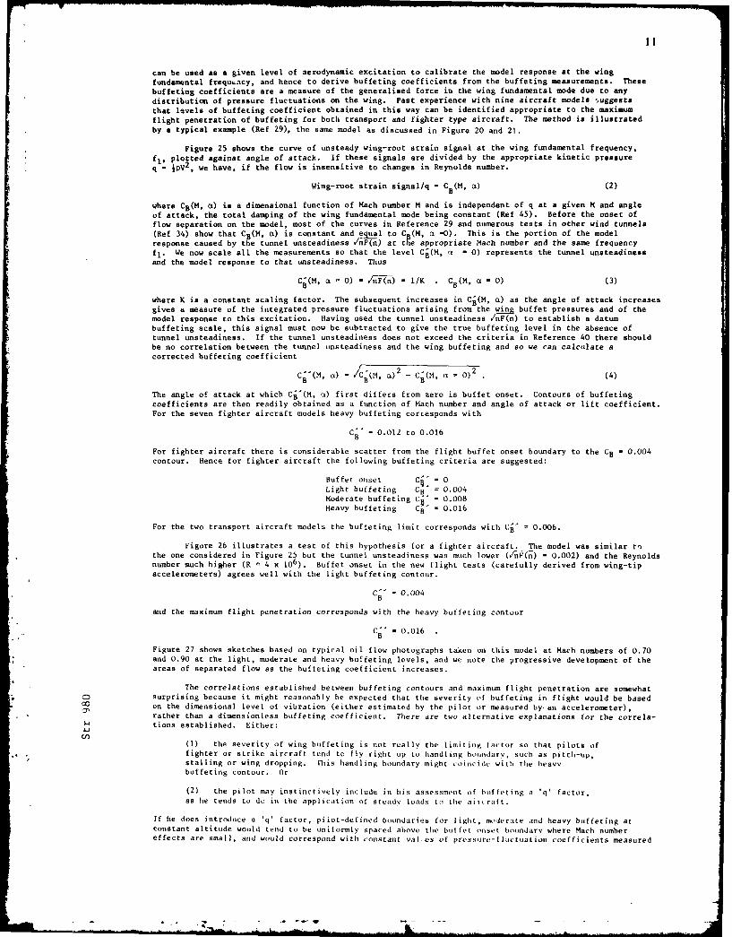
can be used as a given level of aerodynamic excitation to calibrate the model response at the wingfundamental frequ~acy, and hence to derive buffeting coefficients from the buffeting measurements. Thesebuffeting coefficients are a measure of the generalised force in the wing fundamental mode due to anydistribution of pressure fluctuations on the wing. Past experience with nine aircraft models ,uggeststhat levels of buffeting coefficient obtained in this way can be identified appropriate to the maximumflight penetration of buffeting for both transport and fighter type aircraft. The method is illustratedby a typical example (Ref 29), the same model as discussed in Figure 20 and 21.
Figure 25 shows the curve of unsteady wing-root strain signal at the wing fundamental frequency.fl, plotted against angle of attack. If these signals are divided by the appropriate kinetic pressureq - IpV
2, we have, if the flow is insensitive to changes in Reynolds number.
Wing-root strain signal/q = CB(M, B ) (2)
where CB(M, 0) is a dimensional function of Mach number M and is independent of q at a given M and angleof attack, the total damping of the wing fundamental mode being constant (Ref 45). Before the onset offlow separation on the model, most of the curves in Reference 29 and numerous tests in other wind tunnels(Ref 34) show that CB(M, CL) is constant and egl to C (H, c -0). This is the portion of the modelresponse caused by the tunnel unsteadiness /nF(n) at te appropriate Mach number and the same frequencyfl. We now scale all the measurements so that the level Cj(M, u. - 0) represents the tunnel unsteadinessand the model response to that unsteadiness. Thus
C c(, a - 0) - ,'nF(n) - I/K . C8(M, O - 0) (3)
where K is a constant scaling factor. The subsequent increases in Cj(M, ct) as the angle of attack increasesgives a measure of the integrated pressure fluctuations arising from the wing buffet pressures and of themodel response to this excitation. Having used the tunnel unsteadiness /nF(n) to establish a datumbuffeting scale, this signal must now be subtracted to give the true buffeting level in the absence oftunnel unsteadiness. If the tunnel unsteadiness does not exceed the criteria in Reference 40 there shouldbe no correlation between the tunnel unsteadiness and the wing buffeting and so we can calculate acorrected buffeting coefficient
ci) - Cj(M, ct)2 - (M = 0)2 (4)
The angle of attack at which Cj'(M, c) first differs from zero is buffet onset. Contours of buffetingcoefficients are then readily obtained as a function of Mach number and angle of attack or lift coefficient.For the seven fighter aircraft models heavy buffeting corresponds with
C" - 0.012 to 0.016B
For fighter aircraft there is considerable scatter from the flight buffet onset boundary to the CB - 0.004contour. Hence for fighter aircraft the following buffeting criteria are suggested:
Buffet onset Ci, = 0
Light buffeting CB = 0.004Moderate buffeting C" - 0.008Heavy buffeting CB - 0.016
For the two transport aircraft models the buffeting limit corresponds with Cjo = 0.006.
Figure 26 illustrates a test of this hypothesis for a fighter aircraft. The model was similar tothe one considered in Figure 25 but the tunnel unsteadiness was much lower (C/nF n) - 0.002) and the Reynoldsnumber much higher (R n 4 x 10⁶). Buffet onset in the new flight tests (carefully derived from wing-tipaccelerometers) agrees well with the light buffeting contour.
C -i 0.004
B
and the maximum flight penetration corresponds with the heavy buffeting contour
Co- 0.016
Figure 27 shows sketches based on typical oil flow photographs taken on this model at Mach numbers of 0.70and 0.90 at the light, moderate and heavy buffeting levels, and we note the progressive development of theareas of separated flow as the buffeting coefficient increases.
The correlations established between buffeting contours and maximum flight penetration are somewhatC surprising because it might reasonably be expected that the severity of buffeting in flight would be based00 on the dimensional level of vibration (either estimated by the pilot or measured by an accelerometer),
rather than a dimensionless buffeting coefficient. There are two alternative explanations for the correla-tions established. Either:
t.O(1) the severity of wing buffeting is not really the limiting factor so that pilots offighter or strike aircraft tend to fly right up to handling boundary, such as pitch-up,stalling or wing dropping. This handling boundary might coincide with the heavybuffeting contour. Or
(2) the pilot may instinctively include in his assessment of buffeting a 'q' factor.as he tends to do in the application of steady loads to the aircraft.
If he does introduce a 'q' factor, piiot-defined boundaries for light, moderate and heavy buffeting atconstant altitude would tend to be uniformly spaced above the buffet onset boundary where Mach numbereffects are small, and would correspond with constant vales of pressure-fluctuation coefficients measured

12
in the tunnel and hence of buffeting coefficients, CB (see Figure 16 for the Venom aircraft with asharp leading-edge).
The pilots of transport aircraft generally sit further from the nodal points of the wing fundamentalmode than do pilots of fighter or strike aircraft and would not wish to approach a handling boundary, evenif sufficient thrust were available. Thus for transport aircraft the maximum penetration coefficientCj' - 0.006 seems more reasonable than the value of 0.016 for fighter aircraft. This limit for maximumflight buffet penetration for transport aircraft of Cj' - 0.006 is based on measurements for only twomodels at low Reynolds numbers and may need to be revised as additional tunnel/flight comparisons becomeavailable for this class of aircraft.
The heavy buffeting contour can be given a general physical significance because the buffetingcoefficient ought to be of the same magnitude as the fluctuating normal force coefficient if the flow over
most of the wing is separated and the excitation is well correlated across the wing. The measurements ofPolentz on aerofoils (Ref 52) show a maximum normal force coefficient at low frequencies of about 0.010 to0.020 which brackets the heavy buffeting contour of 0.016. Similarly Figure 13 shows that the maximumfluctuating normal force coefficient at a particular low frequency parameter n - 0.05 for a family ofslender wings varies from about /n-Gn) = 0.008 to 0.010 for A = 450 to rnG0n) = 0.014 to 0.019 for A - 700.These high values or normal force coefficient are obtained when vortex breakdown occurs on the wingsirrespective of the details of the vortex flow (Ref 26).
Aircraft such as the Harrier, in which the spanwise development of flow separations is carefullycontrolled, achieve apprect.bly higher heavy buffeting coefficients than previous aircraft. This factcould have important implications for the structural loading of such aircraft (Ref 53, Section 3.1.3).
One applicaiion of this method utilized buffeting measurements made by Hanson on an aeroelasticmodel of a variable geometry fighter aircraft; the original report repays careful study (Ref 54). Theaeroelastic model was tested in Freon 12 in the NASA Langley Transonic Dynamics Tunnel. The model wasflown on wires and achieved an almost exact duplication of the aircraft mode and dampings for the differentwing sweep angles. As expected, the response measured by the wing-root strain bridge was predominantly inthe wing fundamental mode, at about 16 Hz model scale (Figure 8a of Reference 54), and the damping waspredominantly aerodynamic. (The advantage of using correctly scaled aeroelastic models for buffetingtests is that the response in modes other than the aing fundamental bending can be measured accurately.Thus in Hanson's tests the tail response and fuselage vertical bending were measured. Hence the buffetexcitation parameter (Refs 49 and 50) can also be derived for these widely differing modes).
Figure 28 shows a comparison of the buffeting contours derived from the model tests and the buffetonset and maximum penetration achieved in flight. In the tunnel tests the maximum penetration was notlimited by wing buffeting, but instead either by a limiting tail deflection (the aeroelastic model mustfly trimmed) or by a roll instability which the "pilot" could not control. Similarly in flight nomanoeuvres were aborted due to the severity of buffeting, but only due to the attainment of the "g" and'" limits mentioned in the report. Fox A - 260 and 50' the flight buffet onset boundary agrees fairlywell with the buffet onset contour C' - 0 derived from the tunnel tests. F)r = 70' the flight buffetonset boundary is between the bu. et onset contour C0' - 0 and the light buffeting contour C0'- 0.004.Above buffet onset the flight and tunnel contours look similar and support the broad conclusion thatmaximum flight penetration would have corresponded fairly well with the heavy buffeting contour Cj'j 0.O16,if this could have been achieved on the aeroelastic model. Even with the seve'e restrictions applied tothe aeroelastic model by the tail deflection and the roll instability, maximum levels of C'- 0.010 and0.013 were achieved for A - 26' and 700 respectively.
These results from an aeroelastic model flown on wires may reasonably be viewed as a severe, andyet fairly satisfactory, test of the hypothesis originally advanced in Reference 30 on the basis of testson ordinary wind tunnel models supported by stings. It should be noted that buffeting tests on anordinary sting-supported model of the aircraft would not have been limited by tail loads or a rollinstability, and could probably have been made at higher Reynolds numbers. (The test Reynolds numbersquoted on page 10 of Reference 54 are in fact Reynolds numbers/ft so that the model Reynolds numbers arecomparatively low, although this did not spoil the buffeting measurements).
It is interesting to note that in both the flight and tunnel tests reported in Reference 54 rapidincreases in angle of attack excited less severe buffeting than slow increases in angle of attack. Thiseffect has been noticed previously in flight tests of other combat aircraft. Although part of the delaycan be attributed to the finite time taken by the structure to respond to the aerodynamic excitation (asdiscussed by Zbrozek and Jones in Reference 5), there is some evidence that there may well be, inaddition, a transient effect on the development of the flow separations, if the rate of change of theangle of attack is bigh.
Buffeting measurements have also been made on a model of composite construction which representsthe static bending and torsional stiffness of an aircraft project, but not the inertia distribution (Ref 55). rtAlthough this composite model was not a full aeroelastic model, having unrepresentative frequency para-meters, it was more representative of the aircraft than the solid aluminium model tested for comparison. '.The composite model provided useful advance warning of a "torsional buzz" phenomenon subsequently observed Oin flight, which lies in the "no mans-land" between buffeting and flutter, and which did not occur on thesolid model. There is still some doubt as to precisely how the pressure fluctuations on the wing couplewith the torsional vibration, which is only observed with a leading-edge sweep angle of 27.20 in a smallregion about a Mach number of about 0.70 and an incidence of 90 (Ref 55, Fig 17). In some unpublishedtests on an ordinary, steel wind tunnel model with almost the same geometry a large discrete excitationwas observed in the same region at the same frequency parameter, although there was no structural mode onthe model at that frequency.
Recent research on ordinary wind tunnel models has confirmed that in general the wing bending doesnot influence the measured oscillatory pressures when the flow is separated, (This may be seen directlyfrom Figs 16 to 19 of Ref 56 or inferred from the buffeting measurements of Ref 50). The unsteady
13
pressures measured on ordinary wind tunnel models provide a useful indication of any unusual discreteexcitation in the spectrum (as occurs with the circular cylinder). These pressures may. in principle, beintegrated to give the total excitation (Ref 57). However the aircraft response can only be calculatedwith some additional assumption about the total damping in the mode. Hence most future predictions of theseverity of buffeting will continue to be made from accelerometer or wing-root strain measurements, usingeither the buffet excitation parameter (Ref 49) or buffeting coefficients (Ref 30).
Buffeting Tests in Cryogenic Wind Tunnels
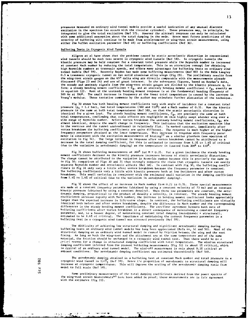
Kilgore et al have shown that the problems caused by static aeroelastic distortion in conventionalwind tunnels should be much leas severe in cryogenic wind tunnels (Ref 58). In cryogenic tunnels thekinetic pressure may be held constant for a constant total pressure while the Reynolds flUmber is increasedat constant Mach number by reducing the total temperature. This is an attractive concept for obtaininghigh Reynolds numbers at transonic speeds, and offers many advantages for buffeting tests on ordinary windtunnel models (Ref 59). Recently Boyden has made some buffeting measurements (Ref 60) in the NASA Langley0.3 m transonic cryogenic tunnel on two solid aluminium alloy wings (Fig 29). The preliminary results fromthe wing-root strain gauges on the 650 delta wing are directly comparable with the measurements alreadydiscussed (Figs 23 and 24) and are of great interest. In the subsequent figures, based on Boyden's data,the steady and unsteady signals from the wing-root strain gauges are divided by the kinetic pressure q, toform: a steady bending moment coefficient - CB, and an unsteady bending moment coefficient - CB, exactly asin equation (2). Most of the unsteady bending moment response is at the fundamental bending frequency of500 Hz at 300K
. The small increase in frequency at the lower total temperature is caused by the increase in
Young's modulus. These tentative comments by the author may stimulate further discussion of the technique.
Fig 30 shows how both bending moment coefficients vary with angle of incidence for a constant totalpressure (Pt - 1.2 bar), two total temperatures (300 and llO) and a Mach number of 0.35. Now the kineticpressure is the same at both total temperatures (Ref 58), so that the static aeroelastic distortion isidentical for a given load. The steady bending moment coefficients, Cp, are precisely the same at bothtotal temperatures, confirming that scale effects are negligible on this highly swept slender wing over awide range of Reynolds number. Before vortex breakdown the unsteady bending moment coefficients, CB, arealmost identical, despite the small change in frequency. This indicates that the excitation spectrum (dueto the vortices and the tunnel unsteadiness) is relatively flat. In marked contrast, immediately aftervortex breakdown the buffeting coefficients are quite different. The response is much higher at the higherfrequency parameters obtained at the lower temperature. This increase in response with frequency para-meter is consistent with the excitation measurements of Keating
27 on a similar planform (see spectrum of
excitation in Fig 34). The large increase in response after vortex breakdown cannot be attributed to adecrease in the total damping coefficient, for this is estimated to increase from 1.3% to 1.6% of critical(due to the variation in aerodynamic damping) as the temperature is lowered from 30 0K to IIO.
Fig 31 shows buffeting measurements at 300K for M = 0.35. For a given incidence the steady bendingmoment coefficients decrease as the kinetic pressure increases because of static aeroelastic distortion.The change cannot be attributed to the variation in Reynolds number because this is precisely the same asin Fig 30; comparison of Figs 30 and 31 thus strongly supports the claim that cryogenic tunnels can easilyseparate Reynolds number and aeroelastic effects (Ref 58). In contrast with Fig 30, the buffeting coeffi-cients in Fig 31 only vary a little after vortex breakdown because the frequency parameter is constant.The buffeting coefficients vary a little with kinetic pressure both at low incidences and after vortexbreakdown. This small variation is consistent with the estimated small variation in the damping coefficientfrom 1.4% to 1.6% of critical (due to the variation in aerodynamic damping).
Fig 32 shows the effect of an increase in Mach number from 0.21 to 0.35. These special measurementsare made at a constant frequency parameter (obtained by using a constant velocity of 73 ms) and at constantkinetic pressure (obtained by using a constant density). When these two parameters are constant, the aero-dynamic damping, proportional to the product of density x velocity, is constant. The steady bending momentcoefficients increase rapidly with Mach number; the increase in bending moment coefficient looks appreciablylarger than the expected increase in lift-curve slope. In contrast, the buffeting coefficients are virtuallyidentical both before and after vortex breakdown, despite the difference in Mach number and the correspondingdifferences in the steady bending moment coefficients. The excellent agreement between both sets ofbuffeting coefficients after vortex breakdown is a direct consequence of maintaining a constant frequencyparameter, and, to a lesser degree, of maintaining constant total damping (aerodynatic + structural),estimated to be l.b% of critical. The importance of maintaining the correct frequency parameter in abuffeting test in a cryogenic wind tunnel was stressed previously (Ref 59).
The difficulty of achieving low structural damping and significant aerodynamic damping duringbuffeting tests on ordinary wind tunnel models has long been appreciated (Refs 44, 51 and 50). Most of thestructural damping on an ordinary wind tunnel model is caused by friction betweel, the wing and the rootfixing. As long as both the wing-root and the attachment are at the same temperature and of the samematerial, the friction should be unchanged in a cryogenic wind tunnel test. Then there would be no arfori reason for a change in structural damping coefficient with total temperature. The wind-on structural
damping coefficient inferred from the present buffeting measurements (Fig 31) is about 1% critical, whichis typical of an ordinary wind tunnel model. The wind-off measurement is only about 0.3% critical atambient conditions. The aerodynamic damping coefficient wos estimated theoretically (Ref 50).
" )The aerodynamic damping obtained in a buffeting test at constant Mach number and total pressure in a00 cryogenic wind tunnel is 1//Nt (Ref 59). Hence t',e proportion of aerodynamic to structural damping will43, increase at cryogenic temperatures. This will improve the scaling of the aerodynamic damping ratio from
model to full scale (Ref 59).
Some preliminary measurements of the total damping coefficients derived from the power spectra ofthe wing-root strain measurementsbO have been added in proof; these measurements are in fair agreementwith the estimates (Fig 33).
4 I
14
Fig 34 shows the spectrum of the excitation measured2 7
at vortex breakdown for the sam cu.litionaas Fig 16. Although the geometry of the BAC 221 was appreciably different from a 650 delta wing, it isknown that the flows on both wings are broadly comparable. The large increase in excitation from afrequency parameter, fc 9/V, from 0.8 to 1.4 is conaistent with the increase in response shown in Fig 30.The spectrum of the excitation measured on unswept rectangular wings is generally flatter than that shownin Fig 34, and hence Boyden's buffeting measurements
60 on the other wing shown in Fig 29 are not sensitive
to the variation in frequency parameter.
4 THEORETICAL METHODS
Numerical methods have been developed now to solve the full Navier-Stokes equations for two-dimensional flows, with a choice of different turbulence models. Chapman has given a comprehensive reviewof these interesting recent developments (Ref 61).
These methods can predict the unusual periodic flows sometimes generated by shock induces' separationson aerofoils over a narrow range of Mach numbers at transonic speeds. The predicted and observed flowson an 18% thick biconvex aerofoil at zero incidence are discussed in Refs 62 and 63. Fig 35 shows a recentexample of such a periodic flow at M - 0.85 on a 147 thick biconvex aerofoil at zero Incidence. The flowpredicted by L Levy of NASA Ames is in excellent agreement with the measurements made at RAE, both withrespect to the lift and moment fluctuations and the frequency (Ref 64). These large periodic pressuresare developed without any aerofoil motion.
On a flexible wing, excitation as large as this could produce serious buffeting, if the frequencycoincides with a structural mode. The frequency parameter, fc/V, lies in the range from 0.1 to 0.2 andthus the wing torsion or overtone bending modes are more likely to be excited than the first bending mode.
Chapman has remarked that so far these methods have only predicted the pressure fluctuations causedby low frequency, large scale flow separations. The methods have not succeeded in predicting the randompressure fluctuations in the normal excitation spectrum, caused by the smaller eddies. The methods arenot yet applicable to three-dimensional flows.
5 CONCLUSIONS
The main themes relate to Figure 4, and can he reiterated as follows; (1) For bubble flows, whichoccur in many different situations, the largest excitatbon is found just upstream of the reattachment point;(2) For slender wings with sharp leading-edges the buffeting is light, but just measurable, exactly aspredicted from wind tunnel tests 8 to 10t years in advance oif flight; and (3) For swept wings the complexnature of the flows and wing pe vfocmanc a,,ssesment are best examined by buffeting measurements on rigidmodels, despite their limitations.
Recent developments inc lode the use of ordinary modelIs in cryogenic wind tunnels (to predict theaircraft response) and the numnerical so lut ion of the full Navier-Stokes equations (to predict the aerodynamicexcitation in periodic flows). Roth methods may ultimately be of interest in evaluating aircraft perfor-mance beyond the butffet boundar%'.
REFERENCES
I -r'2.' "12 rh.' A,'':.,to li :..;'lt,'z :4-Comnritt'o on hA ~ ~ _A n,; *. .', .i-~ i;-AAX 2t M, "Icct I on Z 1tJti 1Id3o.
R4I II0, 1A1iio.arv 19 U.
liek It. -.- 1:. . -.. ,:,.~ .. ;:Y Fra* oL-t,-i,;d:I o ZEN 24,11111. 21-2-., .1lco Fnulisli translation NACA I'M 669.
3 Owen, F. B. ''., e ' Aztz M,',zziiiOM izto !F"irozo,'d in fhe R4i' Luw
I, ... ''~..'z, AGARI) Report 172, 1958.
4 Mahey, P. C. RAI' uint..b ii shedmoss, G.
5 'broizek, I.K. 2. .- Y/ 'i: fournal of Sound and Vibration, Vol.5,* Jones * .1 C. ~No.2,pp0-21,l) .
6 Rogers,. F. W.F. A-: I ti , . , i 17'v Vcpt' -P 7' Jo11k W*Iliq$ it Transonic 4VOLIS.lournal ,t Rival Aeronaut icul Society, Vol.64, pp.
449-4
64, 1960.
G rien , A.1,.. :''o..' 'x :.o:':i..pIp~ no at I',vionic 4)eeda, and theirS.. .:. .':. 1ef' ', AtIARI Cl' 83, 1971.
8 BlackwellI, .).A. 1''.Z : P-:1t-, At:, ." !J;. ' !t;! t' h'- L AtbnI 'P .. tL 1dU~kiV- Layervw i.t. 1! i 'i J f.oni ji'.tCi, NASA TN D 5003. 1969.
En
KIL hi. aan.ii 1) Pup.:.*iJ~1 ~i~i l~ioo of A iroraft t
10 Mahey, [C. ,: ':G 'IIc.i,'VlozIIo in 1ii'O~te' Fla), . 0A IAA Io,ltinal Atigust / Stptember 1972.
11 Norbury, I;.F. A F z';c '' '.' .' ;'t mc,,'"Ifoonai AcJooilo( raltt trev, L. F. ., : C;, irtit: RAF. TN Aero 21452, June 1955.
12 Bradshaw, P. '7 'p. !:I .b ! :I .:. 'i, : i 1 T u111 i -1 11P 7 4'. illP1 Lay I r14,NPl Aero Report 117'1 0c t ol-r 19h5, (Al so pubIi shed as ARC 2 7338).
.5., -S ~ -j-- --- -

15
13 Lilley, G.M. On Wall Pressure Fluctuations in Tuibulent Boundary Layers, ARC 24241,November 1962.
14 Bradshaw, P. The Reattachment and Relaxation of a Turbulent Aear Layer. Journal of
Wong, F.Y.G. Fluid Mechanics, Vol.52, part p 1, pp.113-13 5
, 1972.
15 Lawford, J.A. Law Speed Wind Tunnel Measurements of Pressure Fluctuations on the Wing of
Beauchamp, A.R. a Twin Jet Aircraft (Bristol 188), ARC R&M 3551. 1968.
16 Rose, R. Flight and Tunnel Measurements of Pressure Fluctuations on the Upper Surfaceof the Wing of a Venom Aircraft with a 9arp Leadin.g-Edge. ARC CP 1032.November 1967.
17 Heller, H.H. Incipient Stall Detection through Unsteady-Pressure Monitoring on AircraftBliss, D.B. Wings, Journal of Aircraft, Vol.9, No.2, pp.186-1
88, February 1972.
18 Crabtree, L.F. The Formation of Regions of Separated Flcv on Wing Srfaces, Pt II LaminarSeparation Bubb les and the Mechanism of the Leading-Edge Stall, RAE ReportAero 2578, July 1957, alsi in Pt 2 of ARC R&M 3122, 1959.
19 Jenkins, J.M et al Flight Measurements of Canard Loads, Canard Buffeting and Wing Tip hingeMomenta on the X70 Aircraft Including Comparisons with Predictions,NASA TN D 5359, August 1969.
20 Fricke, F.R. Pressure Fluctuations in a 5eparated Flcw Region, Journal of the Acoustical
Stevenson, D.C. Society of America, Vol.44, No.5, pp.1l89-1201, November 1968.
21 Greshilov, E.M. qectral Characteristics of the Wall Pressure Fluctuations AssociatedwithEvutshenko, A.V. Boundary Layer Separation Behind a Projection on a 3nooth Wall, Soviet
Physics - Acoustics, Vol.15, No.1, pp.29-3
4. July-September 1969.
22 Coe, C.F. The Effects of Some Variations in Launch Vehicle Nose .9ape on Steady andFluctuating Pressures at Transonic *eeds. NASA TM X 646, March 1962.
23 Mabey, D.G. Some Measurements of Base Pressure Fluctuations at .b sonic and %personicqeeds, RAE TR 70 148, August 1970, (also published aa ARC CP 1204, 1972).
24 Mohsen, A.M. Experimental investigation of the Wall Pressure Fluctuations in absonic
Separated Fla). Boeing Co, Report D6-17094, AD669214, January 1967.
25 Moss, G.F. RAE - unpublished.
Mundell, A.R.G.
26 Earnshaw, J.A. Lea &eed Wind Tunnel Experiments on a Sries of . arpEdge elta Wings,
Lawford, J.A. R&M 3424, August 1964.
27 Keating, R.F.A. RAE - unpublished.
28 Dee, F.W. Flight Determination of Wing Fla) Patterns and Buffet Boundaries for theNicholas, O.P. Fairey Delta Aircraft at Mach nunbers be w een 0.4 and 1.3 and Comparison
with Wind Tunnel Tests, R&M 3482, 1964.
29 Mabey, D.G. Comparison of Seven Wing Buffet Boundaries Measured in Wind Tunnels andIn Flight, ARC CP 840.
30 Mabay, D.G. An Hypothesis for the Prediction of Flight Penetration of Wing Buffetingfrom Dynamic Tests on Wind Tunnel Midels, ARC CP 1171, 1971.
31 Mabey, D.C. Measurements of Buffeting on blender Wing Models, ARC CP No.954, 1967.
32 Mitchell, C.G.B. Calculations on the Buffeting on a Slender Wing Aircraft at Lao Speeds,Proceedings of the Symposium on Structural Dynamics, Loughborough
University, March 1970.
33 Huston, W.B. A Study of the Correlation beaeen Flight and Wind Tunnel Buffet Loads.
AGARD Report 121, April 1957, (Also published as ARC 20704).
6 34 Ray, E.G. Buffet and Static Aerodynamnic Characteristics of a *etematics Series of00 Taylor. R.T. Wings Determined from a absonic Wind Tunnel Study, NASA TN D 5805. 1970.0
3. 35 Hollingsworth, E.G. Comparison of Wind Tunnel and Flight Test Techniques for DeterminingCohen, M. Transonic Buffet Charactrist ics on the M-eonnel Douqlas hL4 Airplane,
AIAA Paper No 70-584, 1970.
36 Anon The Effota of Buffeting and othev Tra,,onic l'heowmena on Abtnoeuvrng
Cot,,at Air-raft, A(ARD AR-82, July 1975.
37 Butler, G.F. t'relimiary tocneti'L'ation of a T',,phnipc for Predicting Buffet oads inSpavins, G. Flight fro'm WinL unnel Masur,'mente on A ,,Is of 'onventional Construct ion,
AGARD CP 204.

16
38 John, H. Critical Review of Methods to Predict the Buffet Capbil ity of Aircraft,AGARD Report R623, September 1974.
39 Moss, G.F. The Effect of Leading-Edge Geometry on High *reed &.alling, AGARD CP 102,
Haines, A.R. November 1972, (Also published as RAE TR 72099).
Jordan, R.
40 Mabey, D.G. Floo Unsteadiness and Model Vibration in Wind Tunnels at ab sonic andTransonic Speeds, ARC CP 1155, 1971.
41 Bore, C.L. Post &all Aerodynwnixcs of the "hrrier" CK, AGARD CP 102, November 1972.
42 Pearcey, H.H. Simple Methods for the Prediction of Wing Buffeting Results from Bibb leType %,pa.,ations, NPL Aero Report 1024, June 1962.
43 Mayes, J.F. Traneonic Buffet Characteristics of a 60 Degree & ept Wing with DesignLores, M.E. Variation, AIAA Paper No 69-793, (1969), (Also Journal Aircraft I,Barnard, H.R. pp.
523-530
(1970)).
44 Davis, D.D. Buffet Tests of an Attack Airplane Model jith Emphasis on Data from WindWornom, D.E. Tunnel Tests, NACA RML 57, H13, February 1958.
45 Mabey, D.G. Measurements of Wing Buffeting on a "Ibimitar Model, ARC CP 954, 1966.
46 Jones, J.G. The Dynamic Analysis of Buffeting and Relating Phenomena, AGARD CP 102,November 1972.
47 Butler, G.F. RAE - unpublished. Note in preparation.Jones, J.G.
48 Cornette, E.S. Wind Tunnel lni'entigation of the Effots oof Wing Bodies, Fencea, Flapsand Fuselage Addition on Wing Buffet Resaonse of a Transonic Transportodel, NASA TN D 637.
49 Jones, J.G. Aircraft Dynamic Response Asocit,-d 'th Fluc tuating Fla Fields,AGARD Lecture Series 74, Aircraft Stalling and Buffeting, February 1975.
50 Mabey, D.C. Measurements of Buffeting on T.o 6e," Delta Wings, of Different Materials,Butler, G.F. RAE TR 76-009, also AGARD Paper b, Symposium on Air Frame Response to
Transonic Flow, April 1977.
51 Rainey, A.G. An Examination of Buffeting Arzlhisis !iszd on Kxjr.rm'nts d ith Wings ofByrdsong, T.A. Varying S.tiffness, NASA TN D 3 (1959).
52 Polentz, P.P. The Unsteady Abtmal Force Characteristioa of i- .cted MRCA profiles atPage, W.A. High .bsonic Mach Atebers, NCA RM A 55 002, May 1955.Levy, L.L.
53 Stapleton, S.F. Comments on some Wind Tunnel and Flight Experience of !'ost BuffetPegram, B.V. Behav'iour of the tlrrier Aircraft, Paper 20A1, AGARD CP 187, April 1976.
54 Hanson, P.W. Evaluation of an Aerolastic Mdel Technique for Predicting AircraftBuffeting Loads, NASA TN D 7066, February 1973.
55 Moss, G.F. The Dyn nic Hesponse of Wings in Torsion at High 3 sonic 4)eeds,Pierce, D. Paper 4, AGARD Symposium on Airframe Response to Unsteady Flow, April 1977.
56 Coe, C.F. S.Ikarated Flos Unsteady Pressures and Forces on Elastically RespondingRiddle, D.W. %r'uctures, Paper 1, AGARD Symposium on Airframe Response to Unsteady
Flow, April 1977.
57 Becker, J. Evaluation of Vibration Levels at the Pilot Seat Caused by Wing FlcwDau, K. Separation, Paper 5, AGARD Symposium on Airframe Response to Separated
* Flow, April l' 7.
* 58 Kilgore, R.A. Flight i'nulation Char'actOPstics of the Langley High Reynolds tnberAdcock, J.B. Cryogenic Transonic Tunnel, AIAA Paper 74-80, February 1974.Ray, E.J.
59 Mabey, D.G. .S e Remarks on Piunic Aerolasti M)del Tests in Cryogenic Wind Tunnels,
NASA CR 145029, September 1975.
60 Boyden, R.P. Preliminary Foulsto 'f f' e Tot in a ryonic Wi'd Tunnl,NASA TM- 81923.
61 Chapman, D.R. Computational A,'rodt',nA .I , , e lotm, nt nd Iutlook, AIAA J, Vol.17, No.10,p.1076-1083.
62 Levy, L.L. An 'xje Wr I.'n tal and 'o,Putr ic,zl no .ot it iton of the "tcrad yand Unsteal,[:Trano o,, /ap 77 iel J out ,7 Acr'fil i, a .5',i Wall rest hnn,AIMA Paper 77-678, June 1977.
k- -- m II . ¢ ., ,. .--- w . .. ..
17
63 McDevitt, J.B. S&perriticaZ Flao About a Thick Circu ar Are Aerofoil, NASA TM 78549,January 1979.
64 Mabey, D.G. Measured and Pradicted Periodic FZa., on a 14% Thick Biconvex Wing atWelsh, B.L. Transonic 8pmeds, RAE TR to be issued.Crippe, B.L.
r
4
*" n
• ° 1a
C,
V.
*74 *~~ ~.*
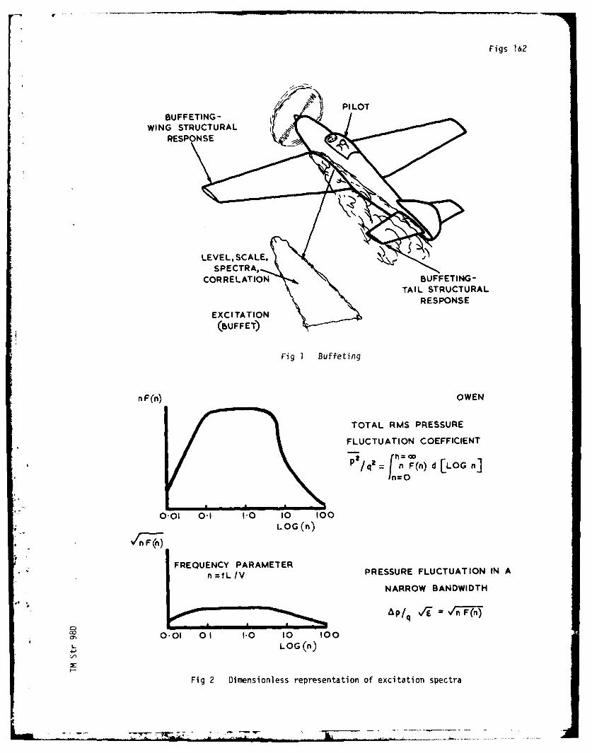
Figs W2
WING STRUCTURALRESPONSE
TAIL STRUCTURALRESPONSE
EXCI TATION
Fig I Buffeting
n F (n) OWEN
TOTAL RMS PRESSURE
FLUCTUATION COEFFICIENT
S/qJn F(n) d [LOG n]
0.01 0.1 hO 10 100* LOG (n)
n=IL/VPRESSURE FLUCTUATION IN A
NARROW BANDWIDTH
AP / q \/_-Vn F(n)
00.01 01 1.0 10 100
LOG (n)
Fig 2 Dimensionless representation of excitation spectra

Figs 3&4
CL
08 % HEY
06- GUST ENCOUNTER125/ LIH
0*4
0-2 - TRANSPORT A= 270
A - I _ I a
v0!4 0 S 0-6 0-7 08 am 0-9MACH NUMBER
CL0.s
0.6
FREQUENTONE0-4 PUJLL-UPS, ULU
0-2FIGHTER A-420 +
L 0-4 0-5 0-6 0.7 0.8 M 0.9MACH NUMBER
Fig 3 Buffeting criteria for transport and fighter aircraft
LOW SWEEP SWEPT SLENDER
WING (SHARP LEADING-EDGES)
FLOW SHOCK WAVES SHOCK WAVES VORTICESBUBBLES BUBBLES
VO0RT ICES
BUFFETING HEAVY HEAVYI/MODERATE/IfLIGHT LIGHT
DIFFICULTY 10 1001
Fig 4 Classification of flows and associated buffeting

Figs 5&6a
CONSTANT PRESSURESHEAR LAYER RAPID PRESSURE
S EOR E C O V E
RY
MEANPRESSURE VARIATION OFSEPARATION POINT fS
JJ
S R
UNSTEADYPRESSURE OBSERVED
rm$
S .... INFERRED FROM VARIATION OF SEPARATION
UNSTEADY OBSERVED -
PRESSURE %
~ rmsINFERRED FROM SHEAR %b~I .~ LAYER STRUCTUREI -
Fig 5 Mean flow and pressure fluctuations caused by separation bubbles
'F ) LAWFORD AND
006 BEAUCHAMP
004P/q
Xt09rms
010 002 - occ=O 8 5
p, = p , ii I p
OO8 01 02 0-4 0 20 40. ni=ft/v
006 A0
O 04
002 X/c c-
050 Aco 085 0
L 00 1.0 20 30
Fig 6a Excitation caused by leading-edge bubble, M = 0.14

Figs 6b,7&8
FRICKE
006L ADINGEE.
00 BUSALE 0
00q 002 -3 SPOILER -NI
9 1 I I - I
01 02 0"4 10 20 40004 nzft/v
002
C=16h -0
0 10 20 30
Fig 6b Excitation caused by a spoiler, M = 0.12
S S
SPECTRUM AT R
5 RS R S
Fig Tpe 01- ItV [-0
Fig 7 Types of bubble flow
OIq
MOHSEN COEr ms LEVELS M
0 06 M-0-33 (2-) M-0 80 AND 119 (3-0)
0 060 04 % SPECTRA NEAR
%'k M-033 REATTACHMENT
*1. ' 004 -0
0 02 M0 s0 0 0
l o002 M.0 33MM-O 19
0 010 X/f 20 01 02 04 10 20 40
n- fI
Fig 8 Comparison of excitation caused by the flow down a step at M = 0.33,0.80 and 1.19
"" " L~ '-':- ... FI .. i I I I* - --- , - - -* ,--,

Figs 9,10-11
I ?
MOSS AND MUNDELLNACA I6 SERIES
08 l, 0 12S R=I OIO
b
04 - A.T _
BUBBLE -. 4.(,*0ICI
0 02 04 06 08 ,lho
O 05 nOO 1
004-10 08 8
0 03 -(WING MODEST ____110I PANEL MODES,00.1 (WN O-. O
0010 02002
0 02 04 06 00x/ (0
Fig 9 Excitation on an aerofoil near buffet onset, M 0.82, : 6.70
SHOCK MOSS AND MUNDELL
TRAILING -EDGE WAVESSEPARATItONSA INTRAILING - EDGE
T N GSEPARATION
THICK SHEAR
LAYER
SHOCKINDUCED
BUBBE fCOMPLETE
SHOCK SEPARATION FLOWWAVESWA VE7 BREAKDOWN
SE AT TIP
SEPARATION
cc- S g c= o
BUFFET ONSET MODERATE BUFFETING
Fig 10 Transonic flow on a swept wing, M = 0.80
MOSS AND MUNDELL
BUFFETING
O 14 -ONSET MODERATE HEAVY
012
010
O OS 5C
00 Ao42 +P OO 0
004 -SHOCK
A
0~ 02SHOCK MOVES SHOCK MOVESDOWNSTREAM UIPST REAM
--
Fig 11 Excitation on a swept wing, M = 0.80
I- *I I I $-i 1 I4I i ,i i" - ,- 11i I -
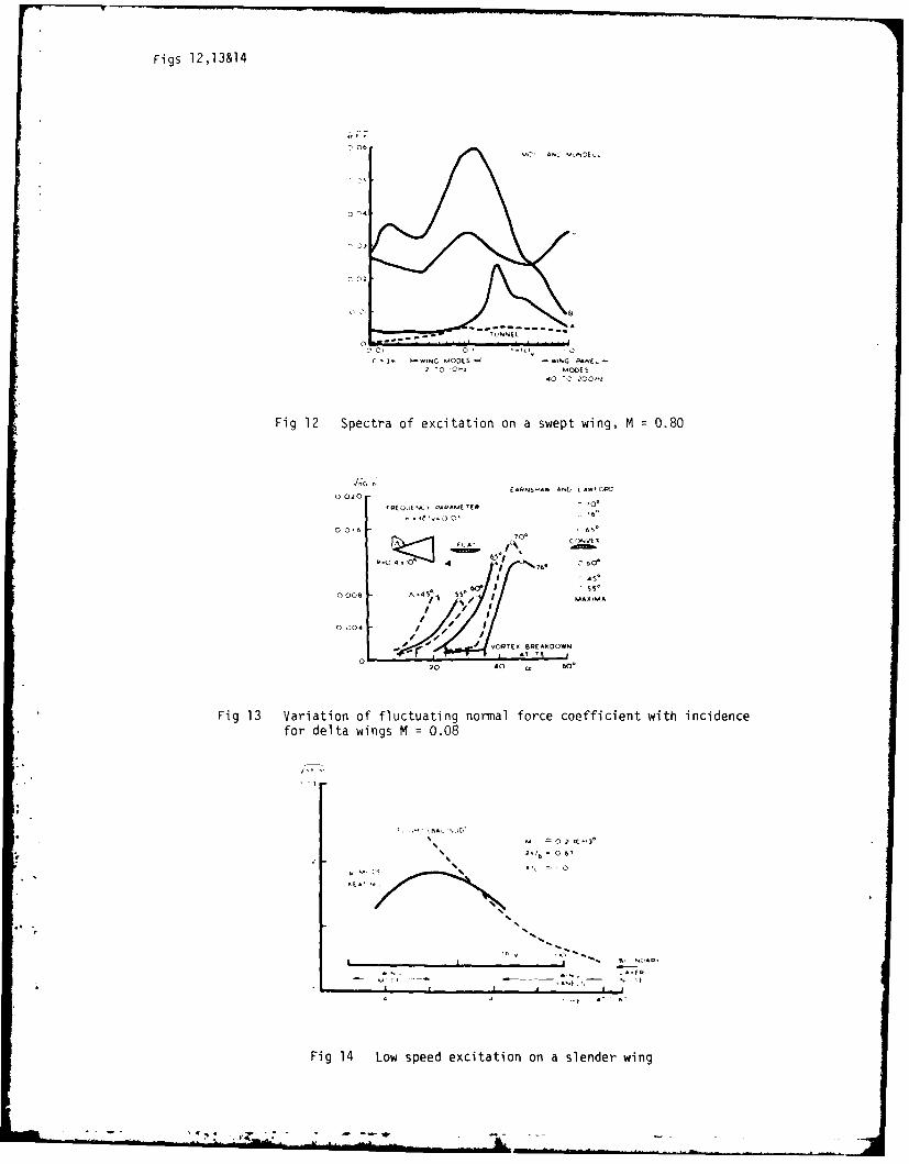
Figs 12,13&14
06N40 AN. 5,INDEL.
03
02c2 c' o' ~ ci
c -'~N ODES -N M4 PNEL-
2- , '014 6Sl 04' O 0
40 '0 200-
Fig 12 Spectra of excitation on a swept wing, M 0.80
(*4 4.5,4* ANb LA*F4 A0020
0 0.6 -65*
Co C'jNV(4
4. A 60'
i 4 I
0006 A45,% j4 I M45MA
o 4 If I
AT YE
20 40 o0
Fig 13 Variation of fluctuating nortal force coefficient with incidencefor delta wings M =0.08
0 .1M 13
:'- 'I' , , ,1 67| , . _ ,
46 1..
Fig 4 Lw sped xcittio on slnderwin
7.4.4

Figs 15,16&17
0 ACCELNA/V
2 X 04
BAC/SUD8 20
CONCORDE
6 IS
AEPOEL AST;C P lGIDMODELRID
4 ~MODEL 1
VORTEX
2 BREAKDOWN
--- VAORTEXFORMATION
0 00 5 10 IS 20 CCO 25 0 5 10 cco 15
Fig 15 Light buffeting on slender wings, M 0.2
CO EATING
150 M 0.
2UST0 ET AL
CONTOUCRS WIN UNTADNS CNORSOT STRAI0 DMPN
TIREATO
Fig 17 Siilarity relA 21ativonse foreadw buffeting
-3 ,M .

Figs 18&19
0 5
CN SPAV INS
FLIGHT
S3 TUNNEL
0 1
RE 10 TO 15 X 106
0'7 08 M 09
Fig 18 Flight/tunnel comparison for buffet onset on a small fighter aircraft
M=0 65 MOSS
I1,xO6 HAINES
BUFFETING A = 350 JORDAN
COEFFICIENT
Cg 0 03 C LEANc, \\ j ",INGO 02-
0 0 I "- SLAT
0 5 10 15 20LI FT
COEFFICIENT INCIDENCE ccw(0)
CL I S SLAT
CLEAN
01 5 WING05
o s 0 ' Sa w)20
TRAILING - EDGE w ( o)
Cp -0 6 CLEAN --
~~WING s-0 4
Y/b=- 0 50
-02 L AT
10 Is 20
*02 •0
.L
Fig 19 Influence of leading-edge slats on buffeting,
forces and trailing-edge pressures
- ~X-ALL

Figs 20&21I
LIFT
COEFFICIENTC L
08a
0-6 -R-13x0O6
ftt G 0
04- RAIN
S2 EPARATIONS SHOWN By OIL FLOW 0 % * *02* LARGE 0
* SMALL 0
000. 0 NONEI
0 0-4 0.5 06 0-7 08 0 9
M1 0
MACH NUMBER
Fig 20 Derivation of flow separation boundaries
LIFTCOEFFICIENT
CL0O e R-1I3XI0 6
06 - 0 6O5 ,1;S 0o
092
Y/b
SEPARATIONS SHOWN BY OIL FLOW: % O002 0 LARGE
e SMALL0 NONE
01 10 0!3 0o4 -0' 0-6 0-7 086 09 M 10
MACH NUMBER
C,
Fig 21 Boundaries of trailing-edge pressure divergenceL
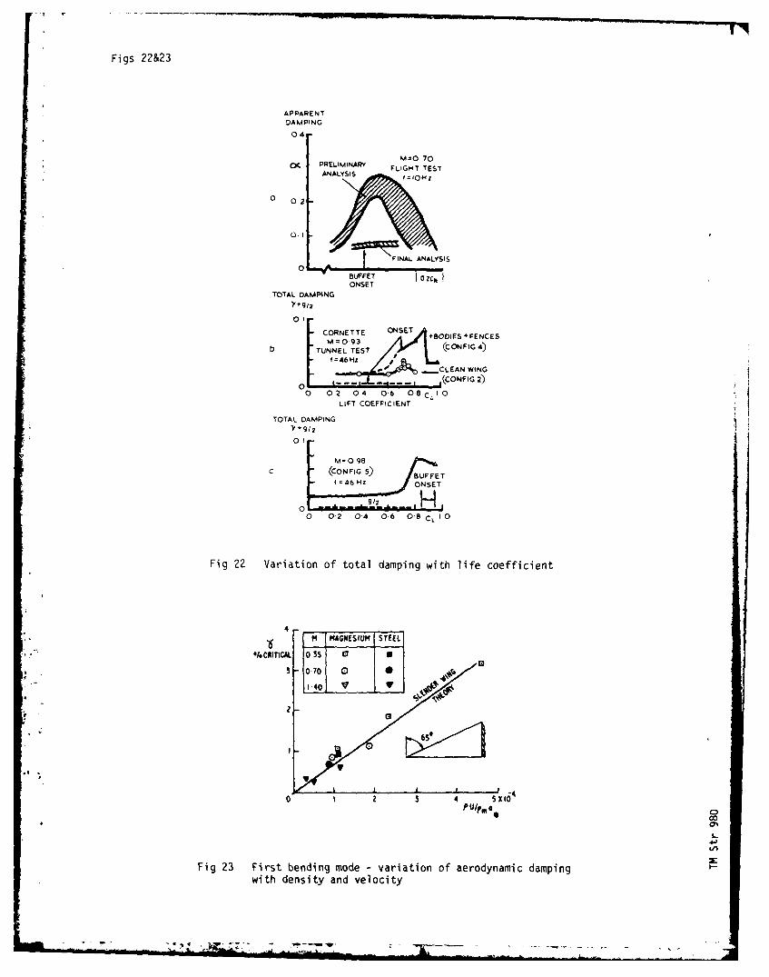
Figs 22&23
APPARENTDAMPING
0-4
M=O 70C PRELIMINARY FLIGHT TEST
ANALYSIS
0 0 2
01 t FINAANALYSIS
BUFFET I 0 ZCNONSET
TOTAL DAMPING"Y+g/2
CORNETTE ONESET
03 +8ODIES+FENCES
b TUNNEL TEST (CONFG),-46Hz
I" -CLEAN WING
--- C- .CONFIG 2)
0 0 2 04 06 OB CL0
LIFT COEFFIC ENT
TOTAL DAMPINGY+9/ 2
01
M. 0 98
C c(CON FIG 5) BUFFET-- f=46 H ONSET
O 02 04 0,6 O'a CL 1 O
Fig 22 Variation of total damping with life coefficient
4"6 MAGNESIUM STEEL
,/oCRITICAL 0 35 0 a
3 0-70 0I
1-40
4' SX1-40 3 4 5KboPul °in 0
Fig 23 First bending mode - variation of aerodynamic dampingwith density and velocity
. .. .-. . +'/,.. .. -;. :-" ..- - "- . .. -- - '-- ... . ... - - . . . . .. "
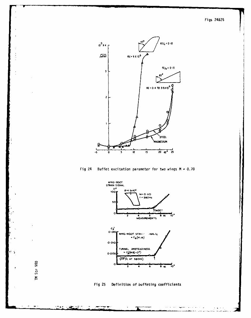
Figs 24&25
Ri 9 X 106"
3
A! R 04 TO 35 X10 6
2 -
14AGNESiUM
-5 0 5 10 15 20 c 25
Fig 24 Buffet excitation parameter for two wings M = 0.70
WING-ROOTSTRAIN SIGNAL
t R-0.3x(06
2 4 6 a cc O0MEASUKMENTS
Cs
OI WING-ROOT STRAW, ,NAL/q;. .Ca (M,=/
0.010
TUNNEL UNSTEAONESS000 Ce(ML 0)
(r-(n) AT SSOH)
00co 2 4 6 a 10'
45b
Fig 25 Definition of buffeting coefficients
- *--.- ------
-
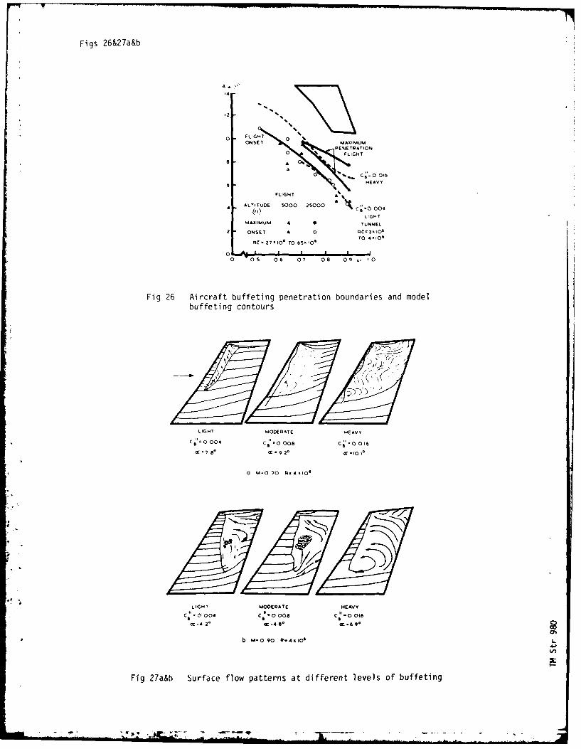
,1 1
Figs 26&27a&b
14
FLIGH0 ONS ET 0 MAXIMUM
PENETRAT ONo FLIGHT
8 A
A
6 HEAVY
FLIGHT A
ALTITUDE 5000 25000 C9=0 0044 (,LIGHT
MAXIMUM A a TUNNEL
2 ONSET A 0 R 3.10,
Rd -27.106 TO 6500 TO 40
o i' * I I I I0 OS 06 07 08 09 0
Fig 26 Aircraft buffeting penetration boundaries and modelbuffeting contours
F1
LIGHT MODERATE HEAVYC. 0 004 C" 0 008 C O I1
ac - Y 8°
c - 9 2* 0C -to I*
a M 070 4.4010'
LIGHT MOOERATE HEAVY
Co0004 CI 0 00 C *0016
c-4 2°
CC ,48 a*-6 9*
b M.O90 gR4.106
4F
rig 27a&b Surface flow patterns at different levels of buffeting

Figs 28&29
- 0JS - L c
'0~. 4Ja
S- u-
.4- 0
z '4- W
0 '4- CO
00 .0-)
Z L4L. -
0 _ _ _ _ __ _ _ _ S-
IIS- C
0 6
0 0CD cn
z 2 6 P I .0 - 4
0 U'D L4- I t4V q$1, I-0
wZW2 -19 4-
us zL 8
-I. I I--L ja
co0
0 0 00CD~ .
00~ oaJ C-m- ) -
S Z
4j0

Figs 30&31
Tt(K) Ptlbar) Rc. x 10'6 q(kNlm2 ) V(M IS)0 300 1-2 1.8 9 6 120
+ 11 1-2 7.1 9.6 73
C8CB CB +/ 00
0/1 CBt ~ 0-04
tc.IV~ 1-4
005
10 20 0C (0) 30
Fig 30 Negligible influence of Reynolds number M =0.35
Tt (K) Pt(bar) RcO x 10T6 q(kINmz) VimIS)O 1-2 18B 9-6x 300 2-9 4.3 24-0 120
0050
0 0 L010 20 Oc~ (0 30
Fig 31 Influence of static aeroelastic distorl*oi M =0.35
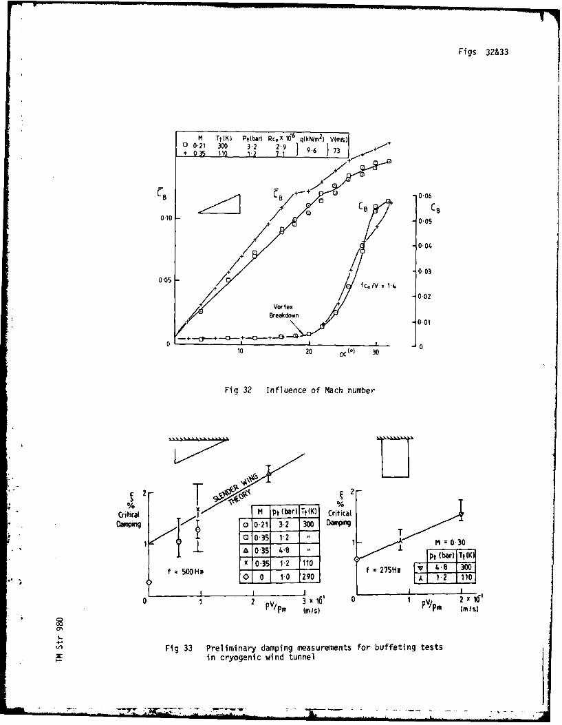
Figs 32&33
M Tt (K) POWba) Rcox 1-6 q(kN/m2)- VIAMls0 0-21 300 3-2 29)
010 5 00596 3
+ 003
0-102
+ 00
Breakdown0.01
0 Cp d-+-o -~.-+ 0 *
10 20 oc(0) 30
Fig 32 Influence of Mach number
%XMpt (bar)I IT(K) Cica
CriticalIt CicaDMing c)021 3.2 300 Damping
0 0-35 1X2 1 T , A--30a~ -35 48 M ±03
0 ptSH (bar) Tt(KW
Wil I 7-a4I 0
0 1 2 P 3 x 160 0 1 PV/ 2X0PVm (MIS) P/m (MIS)
0
V) Fig 33 Preliminary damping measurements for buffeting testsin cryogenic wind tunnel
7~- - -- ~ -
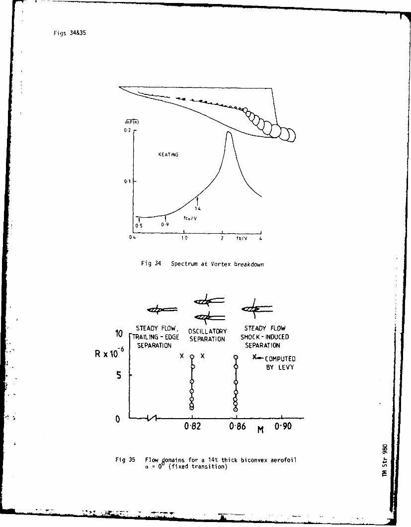
Figs 34&35
In F 7n)
0-2 -
K EATING
0.1
1,4~fc./V
0 5 09
04 10 2 fblv 4
Fig 34 Spectrum at Vortex breakdown
1, STEADY FLOW, OSCLLATORY STEADY FLOW"TRAILING - EDGE SEPARATION SHOCK-INDUCEDSEPARATION SEPARATION
RxdX X X.-COMPUTEDBY LEVY
* 5
0'82 0'86 M 0'90
Fig 35 Flow domains for a 14% thick biconvex aerofoil 4ja= 0 (fixed transition) 4
J
-- ........ - .. ..... - -- , ,-
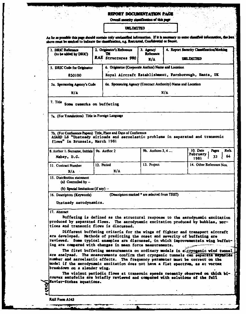
RWQtr 96CWUMUTAI AO
WRLDTSD
As farm- Polakbti "pope bem contain ordy undsulftsd lusfatloa Vf Itsasy toostdam~hifainll fte hexdbiiabove mudi be wg~ed to Wcaste theesetios 0 Restricted, Coskowla or Recrat
I. DRIC Rfeee f 2. Orlginator's Ria3 enc I Agaa 4.Rprtor(to be W"d by DRIC) INI Refe4rencer
RAE Structures 98 I r/zra
5. DRIC Code for Originator 6. Originator (Corporat Author) Nam and Location
850100 Royal Aircraft Establishment, Faruborough, Hents, UK
5a. Sponsoring Agecys Code 6L. Sponsoring Agency (Contract Authority) Name and Location
N/A N/A
7. Title Some remarks on buffeting
7L. (For Translations) .Title in Foreign Language
7b. (For Conference Papers) Title, Place and Date of ConferenceAG&RD LS "Unsteady airloads and aeroelastic problems in separated and tranbonicflows" in Brussels, March 1981
8. Author!1. Surname, Initials 9a. Author 2 9b. Authors 3,4 .... 110. Date Pages Refs.Mahey, D.G. 11981ar 133 164
I1I. Contract Number 12, Period 13. Project f14. Other Reference Nos.
N/A N/A .15. Distribution statement
(a) Controlled by -(b) Specia limitations (if any) -
16. Descriptors (Keywords) (Descriptors marked are selected from TEST)
Unsteady aerodynamic.
17. AbstractBuffeting is defined as the structural response to the aerodynamic excitttion
produced by separated flows. The aerodynamic excitation produced by bubbles,,vor-tices and transonic flows is discussed.
* Different buffeting criteria for the wings of fighter and transport aircraftare developed. Methods of predicting the onset and severity of buffeting arereviewed. Some typical examaples are discussed, -in whichimeproveimantsin win& buffet-in are coweared with changes in mean force measurements. .- ---
The first buffeting measurements on ordinary models in a eic wind tunnelare analysed. The measuremeants confirm that cryogenic tumnels caznM~":W-&tr; WNla-numer and aeroelastic effects. The frequency parmter must be correct on themodel if the aerodynasmic excitation does not have a flat spectrum, as at vortexbreakdown on a slender wing.
The violent periodic flows-at transonic speed* reenotly observed an thick bi-convex aerofoils are briefly reviewed end compared with solutions of the fulftXaveier-Stokes isquatious.
RAE Porm A143