Embed Size (px)
Citation preview

ROUTING CONSORTIUM
Open Shortest Path First (OSPF) Operations Test Suite
Technical Document
Revision 2.9
University of New Hampshire 121 Technology Drive, Suite 2 InterOperability Laboratory Durham, NH 03824-3525 Routing Consortium Phone: +1-603-862-3941 http://www.iol.unh.edu Fax: +1-603-862-4181
© 2008 University of New Hampshire InterOperability Laboratory

University of New Hampshire InterOperability Laboratory
MODIFICATION RECORD Version 2.9 Complete July 11, 2008
• Renamed Test Event Back to Event Backup Seen • Redrew Diagram and Revised Procedure on Test DR Collision • Removed Receiving Old LSAs Part B (RFC 1583), added Possible Problem • Redrew Diagram on Test Basic Flooding • Removed Test Area Ranges with RFC 1583 • Redrew Diagram on Test Inter-Area Summary LSAs • Added Possible Problem on Test Area Ranges with RFC 2328 • Redrew Diagram on Test Area Ranges with RFC 2328 • Clarified Test LSAs with Virtual Links • Redrew Diagram on Test Remove Redundant ASE’s • Added TR2 on Test Default Summary-LSA Origination • Redrew Diagram on Test Host bits in AS-External LSAs • Revised Test IP Header Fields • Revised Test No Virtual Links in Stub Area • Removed Test Simple authentication with RFC 1583 • Revised Test Suite Layout
Version 2.8 Complete August 21, 2006
• Revised Test Advertising RIP Routes. • Removed Test Bad LSA Age.
Version 2.7 Complete January 24, 2005
• Revised Test OSPF_CONF_5.7 • Revised Test OSPF_CONF_5.8
Version 2.6 Complete November 17, 2004
• Revised Test OSPF_CONF_2.5 • Removed Test OSPF_CONF_2.8d • Removed metric configurations from OSPF_CONF_3.21 • Revised Test OSPF_CONF_5.7a
Version 2.5 Complete July 27, 2004
• Fixed 2.13 Part E’s Procedure and made editorial changes to Part C Version 2.4 Complete January 29, 2004
Added a Title to tests wi• t • Deleted the Resource Requirements s
th one parection in the Test Organization
ersion 2.3 Complete July 28, 2003
ONF.4.6b
V• Edited Test OSPF_C• Updated Test OSPF_CONF.2.13• Updated Test OSPF_CONF.2.14 • Updated Test OSPF_CONF.2.15 • Updated Test OSPF_CONF.3.2 • Updated Test OSPF_CONF.3.15• Updated Test OSPF_CONF.3.21 • Updated Test OSPF_CONF.4.3
ROUTING CONSORTIUM 1 OSPF Operations Test Suite
University of New Hampshire InterOperability Laboratory
Version 2.2 Complete June 13, 2003 • Removed Test OSPF _CONF.4.11
ersion 2.1 Complete May 27, 2003
er errors
ersion 2.0 Complete ormat PF_CONF.1.1
Version 1.2 Complete
000
• Test suite put into new format
Version 0.4 Complete
97
• Removed Test OSPF_CONF.4.12 • Updated Test OSPF_CONF.5.8
V• Fixed typos and oth
V January 13, 2003
• Test suite put into new f• Added part B to Test OS• Updated Test OSPF_CONF.2.19 • Added Test OSPF_CONF.2.22 • Added Test OSPF_CONF.4.11 • Added Test OSPF_CONF.4.12
July 26, 2001 Version 1.1 Complete February 10, 2 Version 1.0 Complete January 21, 2000
December 8, 1998
Version 0.3 Complete August 10, 1998 Version 0.2 Complete June 24, 1998 First Version Complete November 4 19
ROUTING CONSORTIUM 2 OSPF Operations Test Suite
University of New Hampshire InterOperability Laboratory
ACKNOWLEDGMENTS The University of New Hampshire would like to acknowledge the efforts of the following individuals in the development of this test suite. Eric Barrett University of New Hampshire David Bond University of New Hampshire Michael Briggs University of New Hampshire Ethan Burns University of New Hampshire Michael Cleary University of New Hampshire Kim Cutting University of New Hampshire Barbara Hill University of New Hampshire Kimo Johnson University of New Hampshire Ray LaRocca University of New Hampshire Dr. William Lenharth University of New Hampshire John Leser University of New Hampshire Adam Lowe University of New Hampshire Dan Maftei University of New Hampshire Jeremy McCooey University of New Hampshire Kari Revier University of New Hampshire Cathy Rhoades University of New Hampshire Sebastien Roy University of New Hampshire Ben Schultz University of New Hampshire Quaizar Vohra University of New Hampshire
ROUTING CONSORTIUM 3 OSPF Operations Test Suite

University of New Hampshire InterOperability Laboratory
INTRODUCTION Overview The University of New Hampshire’s InterOperability Laboratory (IOL) is an institution designed to improve the interoperability of standards based products by providing an environment where a product can be tested against other implementations of a standard. This suite of tests has been developed to help implementers evaluate the functioning of their Open Shortest Path First (OSPF) products. The tests do not determine if a product conforms to the OSPF Specification, nor are they purely interoperability tests. Rather, they provide one method to isolate problems within a device. Successful completion of all tests contained in this suite does not guarantee that the tested device will operate with other OSPF devices. However, combined with satisfactory operation in the IOL’s semi-production environment, these tests provide a reasonable level of confidence that the Router Under Test will function well in most multi-vendor OSPF environments. Test Software and Descriptions The UNH IOL Testing Software is not a full OSPF implementation; it is simply a packet generator that can transmit and receive packets. This allows the Testing Router to generate invalid packets. The Testing Software is not currently available to the public. The UNH IOL test descriptions outlined here are made available to members of the IPv4 Consortium. Abbreviations and Acronyms ASBR: AS Boundary Router ABR: Area Border Router AS: Autonomous System BDR: Backup Designated Router DD: Database Description DR: Designated Router G: Generator LSA: Link State Advertisement M: Monitor or packet capturer MTU: Maximum Transmission Unit N: Network NBMA: Non-Broadcast Multi-Access RUT: Router Under Test Summary-ASBR-LSA: type 4 summary-LSA Summary-Network-LSA: type 3 summary-LSA TR: Testing Router
ROUTING CONSORTIUM 4 OSPF Operations Test Suite

University of New Hampshire InterOperability Laboratory
TEST ORGANIZATION This document organizes tests by group based on related test methodology or goals. Each group begins with a brief set of comments pertaining to all tests within that group. This is followed by a series of description blocks; each block describes a single test. The format of the description block is as follows: Test Label:
The test label and title comprise the first line of the test block. The test label is composed by concatenating the short test suite name, the group number, and the test number within the group, separated by periods. The Test Number is the group and test number, also separated by a period. So, test label OSPF_CONF.1.2 refers to the second test of the first test group in the OSPF Conformance suite. The test number is 1.2.
Purpose: The Purpose is a short statement describing what the test attempts to achieve. It is usually phrased as a simple assertion of the feature or capability to be tested.
References: The References section lists cross-references to the specifications and documentation that might be helpful in understanding and evaluating the test and results.
Discussion: The Discussion is a general discussion of the test and relevant section of the specification, including any assumptions made in the design or implementation of the test as well as known limitations.
Test Setup: The Test Setup section describes the configuration of all devices prior to the start of the test. Different parts of the procedure may involve configuration steps that deviate from what is given in the test setup. If a value is not provided for a protocol parameter, then the protocol’s default is used for that parameter.
Procedure: This section of the test description contains the step-by-step instructions for carrying out the test. These steps include such things as enabling interfaces, unplugging devices from the network, or transmitting packet from a test station. The test procedure also cues the tester to make observations, which are interpreted in accordance with the observable results given for that test part.
Observable Results:
This section lists observable results that can be examined by the tester to verify that the RUT is operating properly. When multiple observable results are possible, this section provides a short discussion on how to interpret them. The determination of a pass or fail for each test is usually based on how the RUT’s behavior compares to the results described in this section.
Possible Problems:
This section contains a description of known issues with the test procedure, which may affect test results in certain situations.
ROUTING CONSORTIUM 5 OSPF Operations Test Suite
University of New Hampshire InterOperability Laboratory
REFERENCES The following documents are referenced in this text: • Request for Comments 2328 − OSPF, Version 2 • Request for Comments 1583 – OSPF, Version 2
ROUTING CONSORTIUM 6 OSPF Operations Test Suite

University of New Hampshire InterOperability Laboratory
TABLE OF CONTENTS
Test OSPF_CONF.1.1: Basic Hello Packet Verification ............................................................... 10 Test OSPF_CONF.1.2: Basic Virtual Link Hello Packet Verification........................................... 11 Test OSPF_CONF.1.3: Hello Waiting ........................................................................................... 12 Test OSPF_CONF.1.4: Event Backup ........................................................................................... 13 Test OSPF_CONF.1.5: No Waiting ............................................................................................... 15 Test OSPF_CONF.1.6: Existing DR .............................................................................................. 16 Test OSPF_CONF.1.7: DR Collision............................................................................................. 17 Test OSPF_CONF.1.8: BDR Becomes DR.................................................................................... 19 Test OSPF_CONF.1.9: DR Other Becomes BDR.......................................................................... 20 Test OSPF_CONF.1.10: Hello Mismatch ...................................................................................... 22 Test OSPF_CONF.1.11: Remote Hello.......................................................................................... 24 Test OSPF_CONF.1.12: E Bit in Hello Packets ............................................................................ 25
2. FLOODING AND ADJACENCY ........................................................................................27 Test OSPF_CONF.2.1: Multi-access Adjacencies ......................................................................... 28 Test OSPF_CONF.2.2: OSPF Database Description MTU Field .................................................. 30 Test OSPF_CONF.2.3: MTU Mismatch ........................................................................................ 31 Test OSPF_CONF.2.4: Master Negotiation ................................................................................... 33 Test OSPF_CONF.2.5: Self-Originated LSA Processing .............................................................. 34 Test OSPF_CONF.2.6: Receiving Old LSAs................................................................................. 35 Test OSPF_CONF.2.7: Neighbor in Lower State than Exchange.................................................. 36 Test OSPF_CONF.2.8: DD Retransmission................................................................................... 37 Test OSPF_CONF.2.9: Event Sequence Number Mismatch ......................................................... 39 Test OSPF_CONF.2.10: Basic Flooding........................................................................................ 42 Test OSPF_CONF.2.11: Flooding AS-External LSAs .................................................................. 44 Test OSPF_CONF.2.12: Flooding LSA Acknowledgements ........................................................ 46 Test OSPF_CONF.2.13: LSA Retransmission............................................................................... 48 Test OSPF_CONF.2.14: LSA Flooding Guarantee........................................................................ 50 Test OSPF_CONF.2.15: LSA Multicast ........................................................................................ 52 Test OSPF_CONF.2.16: Unicast LSA Retransmissions ................................................................ 54 Test OSPF_CONF.2.17: LSA Request Retransmission ................................................................. 55 Test OSPF_CONF.2.18: Bad LSA Requests.................................................................................. 56 Test OSPF_CONF.2.19: MaxAge Flooding................................................................................... 57 Test OSPF_CONF.2.20: LSA Refresh ........................................................................................... 58 Test OSPF_CONF.2.21: LSA Removed from Retransmission...................................................... 59 Test OSPF_CONF.2.22: Neighbor State Down ............................................................................. 60 Test OSPF_CONF.3.1: Transit Link Router LSAs ........................................................................ 63 Test OSPF_CONF.3.2: Router LSAs with DR Changes................................................................ 64 Test OSPF_CONF.3.3: Stub Network Router LSAs...................................................................... 66 Test OSPF_CONF.3.4: Network LSAs with DR Changes............................................................. 68 Test OSPF_CONF.3.5: Attached Routers in Network LSAs ......................................................... 69 Test OSPF_CONF.3.6: Intra-Area Summary ASBR-LSAs ........................................................... 70 Test OSPF_CONF.3.7: Intra-Area Summary Network LSAs........................................................ 72 Test OSPF_CONF.3.8: Inter-Area Summary ASBR LSAs ........................................................... 74 Test OSPF_CONF.3.9: Inter-Area Summary LSAs....................................................................... 76
ROUTING CONSORTIUM 7 OSPF Operations Test Suite

University of New Hampshire InterOperability Laboratory
Test OSPF_CONF.3.10: Inter-area Becomes Intra-area ................................................................ 78 Test OSPF_CONF.3.12: Area Ranges with RFC 2328 .................................................................. 80 Test OSPF_CONF.3.13: Flushing Summary Area Range LSAs.................................................... 82 Test OSPF_CONF 3.14: Transit Area Summary Area Ranges ...................................................... 84 Test OSPF_CONF.3.15: LSAs with Virtual Links ........................................................................ 85 Test OSPF_CONF.3.16: Advertising Static Routes ....................................................................... 88 Test OSPF_CONF.3.17: Advertising RIP Routes.......................................................................... 90 Test OSPF_CONF.3.18: Remove Redundant ASE’s ..................................................................... 92 Test OSPF_CONF.3.19: Default Summary-LSA Origination ....................................................... 94 Test OSPF_CONF.3.20: Default Summary-LSA Use ................................................................... 95 Test OSPF_CONF.3.21: Host Bits in AS-External LSAs.............................................................. 97
4. ROUTE CALCULATION ....................................................................................................99 Test OSPF_CONF.4.1: Intra-Area Paths Preferred...................................................................... 100 Test OSPF_CONF.4.2: Inter-Area Routes through Transit Areas ............................................... 101 Test OSPF_CONF.4.3: ASE Forwarding Addresses ................................................................... 103 Test OSPF_CONF.4.4: Intra-area Routes to an ASBR ................................................................ 105 Test OSPF_CONF.4.5: Preference for Internal Routes................................................................ 107 Test OSPF_CONF.4.6: Type 1 and Type 2 AS-External Routes................................................. 108 Test OSPF_CONF.4.7: Multiple ASBR’s through Intra-area Paths with 1583Compatibility Enabled...................................................................................................................................................... 110 Test OSPF_CONF.4.8: Multiple ASBR’s through Intra-area Paths with 1583Compatibility Disabled........................................................................................................................................ 112 Test OSPF_CONF.4.9: Multiple ASBRs Reachable via Backbone Areas with 1583Compatability...................................................................................................................................................... 114 Test OSPF_CONF.4.10: Multiple ASBRs Reachable via Backbone Areas without 1583Compatability ....................................................................................................................... 116
5. CONFIGURATION AND FORMATTING ......................................................................118 Test OSPF_CONF.5.1: Area Parameters...................................................................................... 119 Test OSPF_CONF.5.2: Interface Parameters ............................................................................... 120 Test OSPF_CONF.5.3: Router LSA Bits ..................................................................................... 121 Test OSPF_CONF.5.4: IP Header Fields ..................................................................................... 123 Test OSPF_CONF.5.5: No Virtual Links in Stub Areas .............................................................. 124 Test OSPF_CONF.5.7: Simple Authentication with RFC 2328 .................................................. 125 Test OSPF_CONF.5.8: MD5 Authentication............................................................................... 127 Test OSPF_CONF.5.9: Incorrect Checksums .............................................................................. 129 Test OSPF_CONF.5.10: #Advertisements Field.......................................................................... 130 Test OSPF_CONF.5.11: Packet Length Field.............................................................................. 132 Test OSPF_CONF.5.12: LSA Header Length Field .................................................................... 133 Test OSPF_CONF.5.13: Router LSA #Links Field ..................................................................... 134 Test OSPF_CONF.5.14: Router LSA #TOS Field....................................................................... 135
ROUTING CONSORTIUM 8 OSPF Operations Test Suite

University of New Hampshire InterOperability Laboratory
GROUP 1: Hello Protocol Overview The following tests verify conformance with the Hello Protocol. Discussion The OSPF Hello Protocol is responsible for establishing and maintaining neighbor relationships. On broadcast and NBMA networks, the Hello Protocol elects a DR for the network. References: RFC 1583 – Sections 7, 8, 9 and 10 RFC 2328 – Sections 7, 8, 9 and 10
ROUTING CONSORTIUM 9 OSPF Operations Test Suite

University of New Hampshire InterOperability Laboratory
Test OSPF_CONF.1.1: Basic Hello Packet Verification Purpose: To verify that the Hello packets are sent every HelloInterval seconds to the IP multicast address AllSPFRouters on broadcast and point-to-point networks. References:
• [2328] Section 9.5 • [1583] Section 9.5
Discussion: On broadcast networks and physical point-to-point networks, Hello packets are sent every HelloInterval seconds to the IP multicast address AllSPFRouters (224.0.0.5). Test Setup: Configure the routers as shown below. If a network is not assigned to a particular area, the default area of 0.0.0.0 is used.
RUT network 0
Procedure: Part A: RUT configured with a HelloInterval of 10 seconds
1. Configure the RUT to have a HelloInterval of 10 seconds. 2. Configure the RUT to broadcast Hello packets on network 0. 3. Observe the packets transmitted on network 0.
Part B: RUT configured with a HelloInterval of 25 seconds 4. Configure the RUT to have a HelloInterval of 25 seconds. 5. Configure the RUT to broadcast Hello packets on network 0. 6. Observe the packets transmitted on network 0.
Observable Results:
• In Part A, the RUT should transmit Hello packets every 10 seconds addressed to AllSPFRouters. • In Part B, the RUT should transmit Hello packets every 25 seconds addressed to AllSPFRouters.
Possible Problems: None.
ROUTING CONSORTIUM 10 OSPF Operations Test Suite

University of New Hampshire InterOperability Laboratory
Test OSPF_CONF.1.2: Basic Virtual Link Hello Packet Verification Purpose: To verify that on virtual links Hello packets are sent as unicast every HelloInterval seconds. References:
• [2328] Section 9.5 • [1583] Section 9.5
Discussion: On broadcast networks, Hello packets are sent multicast; but on virtual links, Hello packets are sent unicast (addressed directly to the other end of the virtual link). Since a virtual link is considered part of the backbone, the Area ID field of all packets being sent across it should be set to 0.0.0.0. Test Setup: Configure the routers as shown below. If a network is not assigned to a particular area, the default area of 0.0.0.0 is used. Configure a virtual link between TR1 and the RUT in Area 1. Configure other parameters appropriately.
Area 1
Backbone
network 0
network 1
RUTTR1
virtual link
Procedure: Part A: Unicast Hello Packets
1. Restart the RUT. 2. OSPF is enabled on TR1. 3. After the RUT and TR1’s databases are synchronized, observe the packets transmitted over the
virtual link.
Observable Results: • In Part A, Hello packets for the virtual link should be sent unicast from the RUT to TR1 every
HelloInterval seconds. The Area ID field of the Hello packets should be set to 0.0.0.0. Possible Problems: None.
ROUTING CONSORTIUM 11 OSPF Operations Test Suite

University of New Hampshire InterOperability Laboratory
Test OSPF_CONF.1.3: Hello Waiting Purpose: To verify that a router does not elect DR or BDR until it transitions out of Waiting state. References:
• [2328] Sections 9.1, 9.2 and 9.3 • [1583] Sections 9.1, 9.2 and 9.3
Discussion: To prevent unnecessary changes of BDR and DR, a router is not allowed to perform DR election until it transitions out of state Waiting. Two events can cause an interface to undergo this transition out of state Waiting: events BackupSeen and WaitTimer. When the router enters state Waiting it starts a timer. Provided that the router does not first transition out of state Waiting by event BackupSeen, event WaitTimer will occur when the timer reaches RouterDeadInterval. Before the timer fires, the router should not declare a DR or BDR in its Hello packets. Test Setup: Configure the routers as shown below. If a network is not assigned to a particular area, the default area of 0.0.0.0 is used. Configure the RUT to have priority 1, RouterDeadInterval 40 and the HelloInterval 10.
RUT network 0
Procedure: Part A: DR and BDR Fields
1. Enable the RUT and wait for more than 40 seconds. 2. Observe the packets transmitted on network 0.
Observable Results:
• In Part A, in the RUT’s first four Hello packets, the DR and BDR fields should be set to 0.0.0.0. In successive Hello packets, the DR field should be the address of the interface to network 0.
Possible Problems: None.
ROUTING CONSORTIUM 12 OSPF Operations Test Suite

University of New Hampshire InterOperability Laboratory
Test OSPF_CONF.1.4: Event Backup Seen Purpose: To verify that event BackupSeen occurs properly and brings an interface out of state Waiting. References:
• [2328] Sections 9.1, 9.2, and 9.3 • [1583] Sections 9.1, 9.2, and 9.3
Discussion: Event BackupSeen occurs when a Hello packet is received from a neighbor claiming to be itself the BDR or when a Hello packet is received from a neighbor claiming to be itself the DR, and indicating that there is no BDR. In either case, the router attempting to transition out of state Waiting must itself be listed in the neighboring router’s field of the appropriate Hello packet. Test Setup: Configure the routers as shown below. If a network is not assigned to a particular area, the default area of 0.0.0.0 is used. Configure the routers to have priority 1, HelloInterval 10 and RouterDeadInterval 40. Configure the other parameters appropriately. Disable all the interfaces.
network 0
RUTTR1 TR2
Procedure: Part A: RUT Transitions out of State Waiting
1. OSPF is enabled on TR1's interface. Wait for more than 40 seconds, so that it becomes DR. 2. Enable the RUT's interface. 3. Observe the packets transmitted on network 0.
Part B: RUT transitions to BDR 4. Disable the RUT's interface. 5. OSPF is enabled on TR2's interface. Wait for more than 40 seconds so that TR2 becomes the
BDR. 6. TR2's interface is unplugged. 7. Enable the RUT's interface and wait longer than RouterDeadInterval. 8. Observe the packets transmitted on network 0.
Part C: RUT transitions to BDR 9. Unplug the RUT’s interface, reset OSPF, and plug the interface back in (TR1 should still list
RUT as BDR). 10. Observe the packets transmitted on network 0.
Part D: TR2 transitions to BDR 11. Disable the RUT's interface. 12. OSPF is enabled on TR2's interface. Wait for 50 seconds so that TR2 becomes BDR. 13. Enable the RUT's interface and wait for more than 20 seconds.
14. Observe the packets transmitted on network 0.
ROUTING CONSORTIUM 13 OSPF Operations Test Suite
University of New Hampshire InterOperability Laboratory
Observable Results: UT should promote itself to BDR after TR1 transmits a Hello packet with the
UT
• claim
• s the BDR on network 0 in its 2nd or 3rd Hello packet.
Possible Problems: None.
• In Part A, the RRUT listed as a neighbor, itself as DR and no BDR. However, it is possible that instead of transmitting such a packet, TR1 will run DR election as soon as it sees the RUT, and will therefore transmit a Hello with the RUT as BDR (instead of 0.0.0.0). In such a case, the Rshould wait for RouterDeadInterval to expire before transitioning out of state Waiting. In Parts B and C, the RUT should wait for approximately 40 seconds before it begins to itself to be the BDR on network 0. In Part D, the RUT should list TR2 a
ROUTING CONSORTIUM 14 OSPF Operations Test Suite
University of New Hampshire InterOperability Laboratory
Test OSPF_CONF.1.5: No Waiting Purpose: To verify that if a router has priority 0 on an interface, the interface state machine does not go through state Waiting but goes directly to DR Other. References:
• [2328] Section 9.3 • [1583] Section 9.3
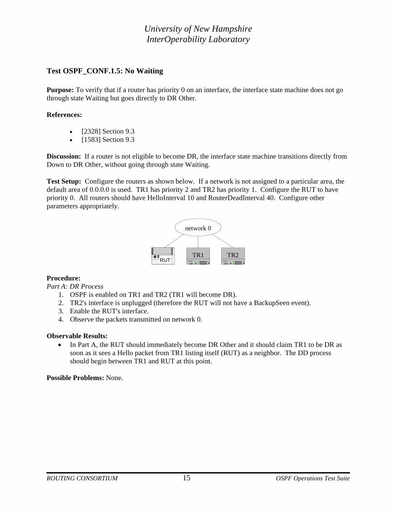
Discussion: If a router is not eligible to become DR, the interface state machine transitions directly from Down to DR Other, without going through state Waiting. Test Setup: Configure the routers as shown below. If a network is not assigned to a particular area, the default area of 0.0.0.0 is used. TR1 has priority 2 and TR2 has priority 1. Configure the RUT to have priority 0. All routers should have HelloInterval 10 and RouterDeadInterval 40. Configure other parameters appropriately.
network 0
RUTTR1 TR2
Procedure: Part A: DR Process
1. OSPF is enabled on TR1 and TR2 (TR1 will become DR). 2. TR2's interface is unplugged (therefore the RUT will not have a BackupSeen event). 3. Enable the RUT's interface. 4. Observe the packets transmitted on network 0.
Observable Results:
• In Part A, the RUT should immediately become DR Other and it should claim TR1 to be DR as soon as it sees a Hello packet from TR1 listing itself (RUT) as a neighbor. The DD process should begin between TR1 and RUT at this point.
Possible Problems: None.
ROUTING CONSORTIUM 15 OSPF Operations Test Suite
University of New Hampshire InterOperability Laboratory
Test OSPF_CONF.1.6: Existing DR Purpose: To verify that when a router's interface to a network first becomes functional, if there is already an existing DR, it accepts that DR regardless of its own priority. References:
• [2328] Section 7.3 • [1583] Section 7.3
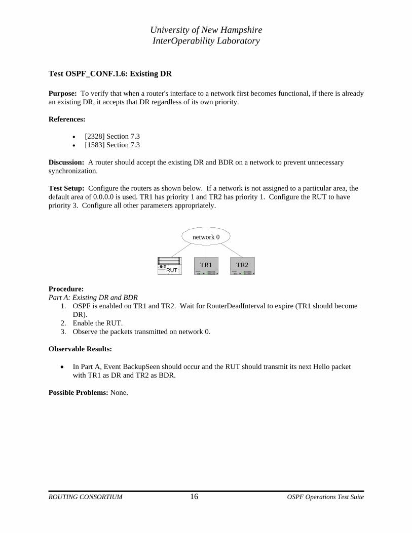
Discussion: A router should accept the existing DR and BDR on a network to prevent unnecessary synchronization. Test Setup: Configure the routers as shown below. If a network is not assigned to a particular area, the default area of 0.0.0.0 is used. TR1 has priority 1 and TR2 has priority 1. Configure the RUT to have priority 3. Configure all other parameters appropriately.
network 0
RUTTR1 TR2
Procedure: Part A: Existing DR and BDR
1. OSPF is enabled on TR1 and TR2. Wait for RouterDeadInterval to expire (TR1 should become DR).
2. Enable the RUT. 3. Observe the packets transmitted on network 0.
Observable Results:
• In Part A, Event BackupSeen should occur and the RUT should transmit its next Hello packet with TR1 as DR and TR2 as BDR.
Possible Problems: None.
ROUTING CONSORTIUM 16 OSPF Operations Test Suite
University of New Hampshire InterOperability Laboratory
Test OSPF_CONF.1.7: DR Collision Purpose: To verify that if two or more routers have declared themselves DR, the one with the highest priority is chosen to be DR. In case of a tie, the one having the highest Router ID is chosen. References:
• [2328] Section 9.4 • [1583] Section 9.4
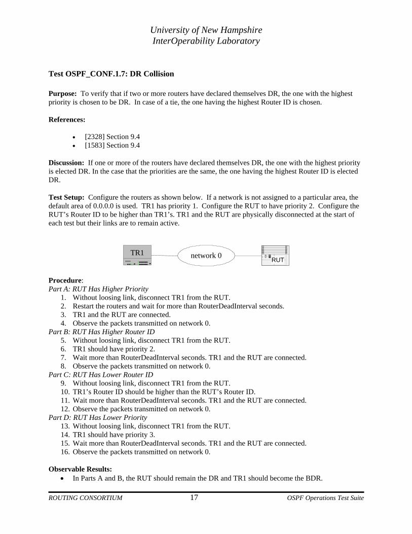
Discussion: If one or more of the routers have declared themselves DR, the one with the highest priority is elected DR. In the case that the priorities are the same, the one having the highest Router ID is elected DR. Test Setup: Configure the routers as shown below. If a network is not assigned to a particular area, the default area of 0.0.0.0 is used. TR1 has priority 1. Configure the RUT to have priority 2. Configure the RUT’s Router ID to be higher than TR1’s. TR1 and the RUT are physically disconnected at the start of each test but their links are to remain active.
RUTnetwork 0TR1
Procedure: Part A: RUT Has Higher Priority
1. Without loosing link, disconnect TR1 from the RUT. 2. Restart the routers and wait for more than RouterDeadInterval seconds. 3. TR1 and the RUT are connected. 4. Observe the packets transmitted on network 0.
Part B: RUT Has Higher Router ID 5. Without loosing link, disconnect TR1 from the RUT. 6. TR1 should have priority 2. 7. Wait more than RouterDeadInterval seconds. TR1 and the RUT are connected. 8. Observe the packets transmitted on network 0.
Part C: RUT Has Lower Router ID 9. Without loosing link, disconnect TR1 from the RUT. 10. TR1’s Router ID should be higher than the RUT’s Router ID. 11. Wait more than RouterDeadInterval seconds. TR1 and the RUT are connected. 12. Observe the packets transmitted on network 0.
Part D: RUT Has Lower Priority 13. Without loosing link, disconnect TR1 from the RUT. 14. TR1 should have priority 3. 15. Wait more than RouterDeadInterval seconds. TR1 and the RUT are connected. 16. Observe the packets transmitted on network 0.
Observable Results: • In Parts A and B, the RUT should remain the DR and TR1 should become the BDR.
ROUTING CONSORTIUM 17 OSPF Operations Test Suite
University of New Hampshire InterOperability Laboratory
• In Parts C and D, TR1 should remain the DR and the RUT should become the BDR.
ossible Problems: None. P
ROUTING CONSORTIUM 18 OSPF Operations Test Suite

University of New Hampshire InterOperability Laboratory
Test OSPF_CONF.1.8: BDR Becomes DR Purpose: To verify that the BDR becomes DR when the previous DR fails. References:
• [2328] Sections 7.4, 9.1, and 9.3 • [1583] Sections 7.4, 9.1, and 9.3
Discussion: In order to make the transition to a new DR smoother, there is a BDR for each multi-access network. When the DR fails, the BDR is promoted to DR, and a new BDR is elected (if there are any eligible routers). Similar to the DR, the BDR is adjacent to all routers on the network. Therefore, when it promotes itself to DR, it does not need to go through the DD process again with any of the routers on the network. Test Setup: Configure the routers as shown below. If a network is not assigned to a particular area, the default area of 0.0.0.0 is used.
network 0
RUTTR1 TR2
Procedure: Part A: Transition to a new DR
1. TR1, the RUT and TR2 should be enabled so that they become DR, BDR, and DR Other, respectively.
2. OSPF is disabled on TR1. 3. Observe the packets transmitted on network 0.
Observable Results: • In Part A, the RUT and TR2 should become DR and BDR respectively. They should not
resynchronize their databases.
Possible Problems: None.
ROUTING CONSORTIUM 19 OSPF Operations Test Suite

University of New Hampshire InterOperability Laboratory
Test OSPF_CONF.1.9: DR Other Becomes BDR Purpose: To verify that when the DR fails, the DR Other with the highest priority becomes BDR, and synchronizes its database with all other routers on the network except for the new DR. References:
• [2328] Sections 9.3 and 9.4 • [1583] Sections 9.3 and 9.4
Discussion: When the DR fails, the BDR is promoted to DR, and a new BDR is elected from the list of any eligible DR Others. Like the DR, the BDR is adjacent to all routers on the network. Therefore, when a DR Other is promoted to BDR, it needs to synchronize with all other routers on the network except the new DR (who it had already previously synchronized with). The same would be true if it were the BDR, not the DR, which failed. Test Setup: Configure the routers as shown below. If a network is not assigned to a particular area, the default area of 0.0.0.0 is used. All TRs should have priority 1. Configure the RUT with priority 2.
network 0
RUTTR1 TR2 TR3
Procedure: Part A: RUT Becomes BDR Due to Priority
1. OSPF is enabled on TR1, TR2, TR3 and the RUT so that they become DR, BDR, DR Other and DR Other, respectively.
2. OSPF is disabled on TR1’s interface to network 0. 3. Observe the packets transmitted on network 0.
Part B: RUT Remains DR Other Due to Lower Priority 4. Configure the RUT to have priority 1. TR3 should have priority 2. 5. OSPF is enabled on TR1’s interface to network 0. 6. OSPF is restarted on all the routers so that TR1, TR2, TR3 and the RUT become DR, BDR, DR
Other and DR Other, respectively. 7. OSPF is disabled on TR1’s interface to network 0. 8. Observe the packets transmitted on network 0.
Part C: RUT Becomes BDR Due to Router ID 9. Configure the RUT to have the same priority as TR3 and configure the RUT’s Router ID to be
greater than TR3’s Router ID. 10. OSPF is enabled on TR1’s interface to network 0. 11. OSPF is restarted on all the routers so that TR1, TR2, TR3 and the RUT become DR, BDR, DR
Other and DR Other, respectively. 12. OSPF is disabled on TR1’s interface to network 0. 13. Observe the packets transmitted on network 0.
ROUTING CONSORTIUM 20 OSPF Operations Test Suite

University of New Hampshire InterOperability Laboratory
Part D: RUT Remains DR Other Due to Lower Router ID 14. Configure the RUT to have the same priority as TR3 and configure the RUT’s Router ID to be
less than TR3’s Router ID. 15. OSPF is enabled on TR1’s interface to network 0. 16. OSPF is restarted on all the routers so that TR1, TR2, TR3 and the RUT become DR, BDR, DR
Other and DR Other, respectively. 17. OSPF is disabled TR1’s interface to network 0 18. Observe the packets transmitted on network 0.
Observable Results:
• In Parts A and C, TR2 should become DR and the RUT should become BDR. The RUT should synchronize with TR3, but not with TR2.
• In Parts B and D, TR2 should become DR and TR3 should become BDR. The RUT should synchronize with TR3, but not with TR2.
Possible Problems: None.
ROUTING CONSORTIUM 21 OSPF Operations Test Suite

University of New Hampshire InterOperability Laboratory
Test OSPF_CONF. 1.10: Hello Mismatch
Purpose: To verify that any mismatch between the Hello packet values Area ID, Network Mask, HelloInterval, RouterDeadInterval and the configuration of the receiving interface cause the packet to be dropped as long as the interface is not part of a point-to-point network or a virtual link. References:
• [2328] Section 10.5 • [1583] Sections 9.5 and 10.5
Discussion: On a multi-access network, the Area ID, Network Mask, HelloInterval, and RouterDeadInterval defined in an incoming Hello packet should match the configuration of the receiving interface. Otherwise, the Hello packet should be dropped and the sender should not be accepted as a neighbor. Test Setup: Configure the routers as shown below. If a network is not assigned to a particular area, the default area of 0.0.0.0 is used. Configure the routers so that their Area ID, Network Mask, HelloInterval and RouterDeadInterval match.
network 0
RUTTR1
Procedure: Part A: Databases Synchronize
1. OSPF is restarted on all the routers. 2. Wait longer than RouterDeadInterval seconds, observe the packets transmitted on network 0.
Part B: Different Area ID’s 3. Configure the RUT’s Area ID to be a value different than TR1’s Area ID. 4. OSPF is restarted on the routers. 5. Wait longer than RouterDeadInterval seconds, observe the packets transmitted on network 0.
Part C: Different Network Masks 6. Reset the RUT’s Area ID to the original value. 7. TR1’s Network Mask is changed to a value different than the RUT’s Network Mask. 8. OSPF is restarted on the routers. 9. Wait longer than RouterDeadInterval, observe the packets transmitted on Network 0.
Part D: Different HelloInterval’s 10. TR1’s Network Mask is reset to the original value and the HelloInterval is changed to a value
different than the RUT’s HelloInterval. 11. OSPF is restarted on the routers. 12. Wait longer than RouterDeadInterval seconds, observe the packets transmitted on network 0.
ROUTING CONSORTIUM 22 OSPF Operations Test Suite

University of New Hampshire InterOperability Laboratory
Part E: Different RouterDeadInterval’s 13. TR1’s HelloInterval is reset to the original value and the RouterDeadInterval is changed to a
value different than the RUT’s RouterDeadInterval. 14. OSPF is restarted on the routers. 15. Wait longer than RouterDeadInterval seconds, observe the packets transmitted on network 0.
Observable Results:
• In Part A, the RUT and TR1 should become neighbors and then synchronize their databases. • In Parts B, C, D, and E, the RUT and TR1 should not become neighbors.
Possible Problems: None.
ROUTING CONSORTIUM 23 OSPF Operations Test Suite

University of New Hampshire InterOperability Laboratory
Test OSPF_CONF.1.11: Remote Hello Purpose: To verify that if an incoming OSPF packet is not from a local network then it is discarded. References:
• [2328] Section 10.5 • [1583] Sections 9.5 and 10.5
Discussion: For an incoming OSPF packet to be accepted, the values configured for the receiving interface must match the packet’s network configuration if the packet is not received on a point-to-point network or a virtual link. Test Setup: Configure the routers as shown below. If a network is not assigned to a particular area, the default area of 0.0.0.0 is used. Configure the RUT to have an address of X.Y.11.1 on network 1 with a netmask 255.255.255.0. TR1 should have an address of X.Y.12.2 on network 1 with a netmask of 255.255.255.0. Configure the RUT to have an address of X.Y.10.1 on network 0 with a netmask of 255.255.255.0. Configure other parameters appropriately. Network 0 is X.Y.10.0/24 and network 1 is X.Y.11.0/24.
network 1
RUTTR1
network 0
Procedure: Part A: Same Network, Different Subnets
1. OSPF is restarted on the routers. 2. Observe the packets transmitted network 0 and network 1.
Part B: Same Subnet, Different Networks 4. OSPF is disabled on the routers. 5. TR1’s address on network 1 is changed to X.Y.10.2. 6. OSPF is restarted on the routers. 7. Observe the packets transmitted on network 0 and network 1.
Observable Results:
• In Parts A and B, the RUT should not list TR1 as a neighbor in its Hello packets. Possible Problems: None.
ROUTING CONSORTIUM 24 OSPF Operations Test Suite

University of New Hampshire InterOperability Laboratory
Test OSPF_CONF.1.12: E Bit in Hello Packets Purpose: To verify that the E bit of the Options field in a Hello packet is set if and only if the attached area is not a stub area. If two routers on a network do not agree on the E bit, they will not become neighbors. References:
• [2328] Sections 9.5 and 10.5 • [1583] Sections 9.5 and 10.5
Discussion: The Hello packet's Options field describes the router's optional OSPF capabilities. The E bit should be set if and only if the attached area is capable of processing AS external advertisements (i.e., it is not a stub area). Incoming Hello packets that have the E bit set differently than the setting on the receiving interface should be dropped. Test Setup: Configure the routers as shown below. If a network is not assigned to a particular area, the default area of 0.0.0.1 is used. The routers should all agree that the area is not a stub area.
network 0
RUTTR1
Procedure: Part A: Both RUT and TR1 in Full Area
1. OSPF is restarted on the routers. 2. Observe the packets transmitted on network 0.
Part B: TR1 in Stub Area 3. TR1 is changed so that the attached area is a stub area. 4. OSPF is restarted on the routers. 5. Observe the packets transmitted on network 0.
Part C: Both RUT and TR1 in Stub Area 6. Configure the RUT so that the attached area is a stub area. 7. OSPF is restarted on the routers. 8. Observe the packets transmitted on network 0.
Part D: Only RUT in Stub Area 9. TR1 is changed so that the attached area is not a stub area. 10. OSPF is restarted on the routers. 11. Observe the packets transmitted on network 0.
Observable Results:
ROUTING CONSORTIUM 25 OSPF Operations Test Suite

University of New Hampshire InterOperability Laboratory
• In Part A, the E bit should be set in the RUT’s Hello packets and TR1 should be listed as a neighbor.
• In Part B, the E bit should be set in the RUT’s Hello packets and not set in TR1’s Hello packets. The RUT should not list TR1 as a neighbor.
• In Part C, the E bit should be not set in either router’s Hello packets. The RUT should list TR1 as a neighbor.
• In Part D, the E bit should be set in TR1’s Hello packets and not set in the RUT’s Hello packets. The RUT should not list TR1 as a neighbor.
Possible Problems: None.
ROUTING CONSORTIUM 26 OSPF Operations Test Suite

University of New Hampshire InterOperability Laboratory
GROUP 2: Flooding and Adjacency Overview The following tests verify the flooding and adjacency procedures of the OSPF protocol. Discussion OSPF routers must maintain synchronized link state databases. This is accomplished in two ways: When a new adjacency is formed between two routers, the routers synchronize their link state databases; When the state of a link changes, a LSA describing the change is flooded throughout the entire area and/or AS, depending on the topology and the type of the LSA. References: RFC 1583 – Sections 10, 12, 13 and 14 RFC 2328 – Sections 10, 12, 13 and 14
ROUTING CONSORTIUM 27 OSPF Operations Test Suite

University of New Hampshire InterOperability Laboratory
Test OSPF_CONF.2.1: Multi-access Adjacencies
Purpose: To verify that on a multi-access network, the DR and BDR become adjacent with all other routers, while a DR Other only becomes adjacent with the DR and BDR. References:
• [2328] Section 10.4 • [1583] Section 10.4
Discussion: On a multi-access network, the DR and BDR should become adjacent with all other routers, while a DR Other becomes adjacent only with the DR and BDR. Two routers try to bring up adjacencies by exchanging DD, Link State Request, Update and Acknowledgement packets. Test Setup: Configure the routers as shown below. If a network is not assigned to a particular area, the default area of 0.0.0.0 is used. All routers should have priority 1. Configure the RUT to have the highest Router ID.
network 0
RUTTR1 TR2 TR3
Procedure: Part A: RUT Becomes Adjacent with DR and BDR
1. OSPF is enabled on the routers so that TR1, TR2 and TR3 become DR, BDR and DR Other, respectively.
2. Enable the RUT. 3. Observe the packets transmitted on network 0.
Part B: RUT Becomes Adjacent with All Routers as BDR 4. OSPF is disabled on TR3’s interface to network 0. 5. OSPF is restarted on the routers so that TR1, the RUT and TR2 become DR, BDR and DR Other,
respectively. 6. OSPF is enabled on TR3’s interface to network 0. 7. Observe the packets transmitted on network 0.
Part C: RUT Becomes Adjacent with All Routers as DR 8. OSPF is disabled on TR3’s interface to network 0. 9. OSPF is restarted on the routers so that the RUT, TR1 and TR2, become DR, BDR and DR Other,
respectively. 10. OSPF is enabled on TR3’s interface to network 0. 11. Observe the packets transmitted on network 0.
Observable Results:
• In Part A, the RUT should form adjacencies with TR1 and TR2. It should not transmit DD packets to TR3.
• In Parts B and C, the RUT should form adjacencies with all routers.
ROUTING CONSORTIUM 28 OSPF Operations Test Suite

University of New Hampshire InterOperability Laboratory
Possible Problems: None.
ROUTING CONSORTIUM 29 OSPF Operations Test Suite

University of New Hampshire InterOperability Laboratory
Test OSPF_CONF.2.2: OSPF DD MTU Field Purpose: To verify that a router properly sets the MTU for its interface to a network in DD packets. References:
• [2328] Section 10.8 Discussion: A router specifies the MTU for its interface to a network in its DD packets in the two octets preceding the Options field. A router should set the Interface MTU Field of its DD packets to the size of the largest IP datagram that can be sent out the sending interface, without fragmentation (i.e. 1500 on Ethernet). This field should be set to zero in DD packets sent across a virtual link. Test Setup: Configure the routers as shown below. If a network is not assigned to a particular area, the default area of 0.0.0.0 is used. Configure the RUT appropriately so that it will become adjacent with TR1.
Area 1
Backbone
network 0
network 1
RUTTR1
virtual link
Procedure: Part A: MTU field Set Properly with No Virtual Link
1. OSPF is restarted on the routers. 2. Observe the packets transmitted on network 0 and network 1.
Part B: MTU field Set Properly with Virtual Link Active 3. Configure the RUT to form a virtual link with TR1 in Area 1. 4. OSPF is restarted on the routers. 5. Observe the packets transmitted on network 0, network 1 and over the virtual link.
Observable Results:
• In Part A, the RUT should set the Interface MTU Field of its DD packets to 1500. • In Part B, the RUT should set the Interface MTU Field of its DD packets sent across the virtual
link to zero. Possible Problems: None.
ROUTING CONSORTIUM 30 OSPF Operations Test Suite
University of New Hampshire InterOperability Laboratory
Test OSPF_CONF.2.3: MTU Mismatch Purpose: To verify that a router properly identifies the MTU for its interface to a network in its DD packets, and any incoming DD packet with an MTU set higher than this value will be dropped. References:
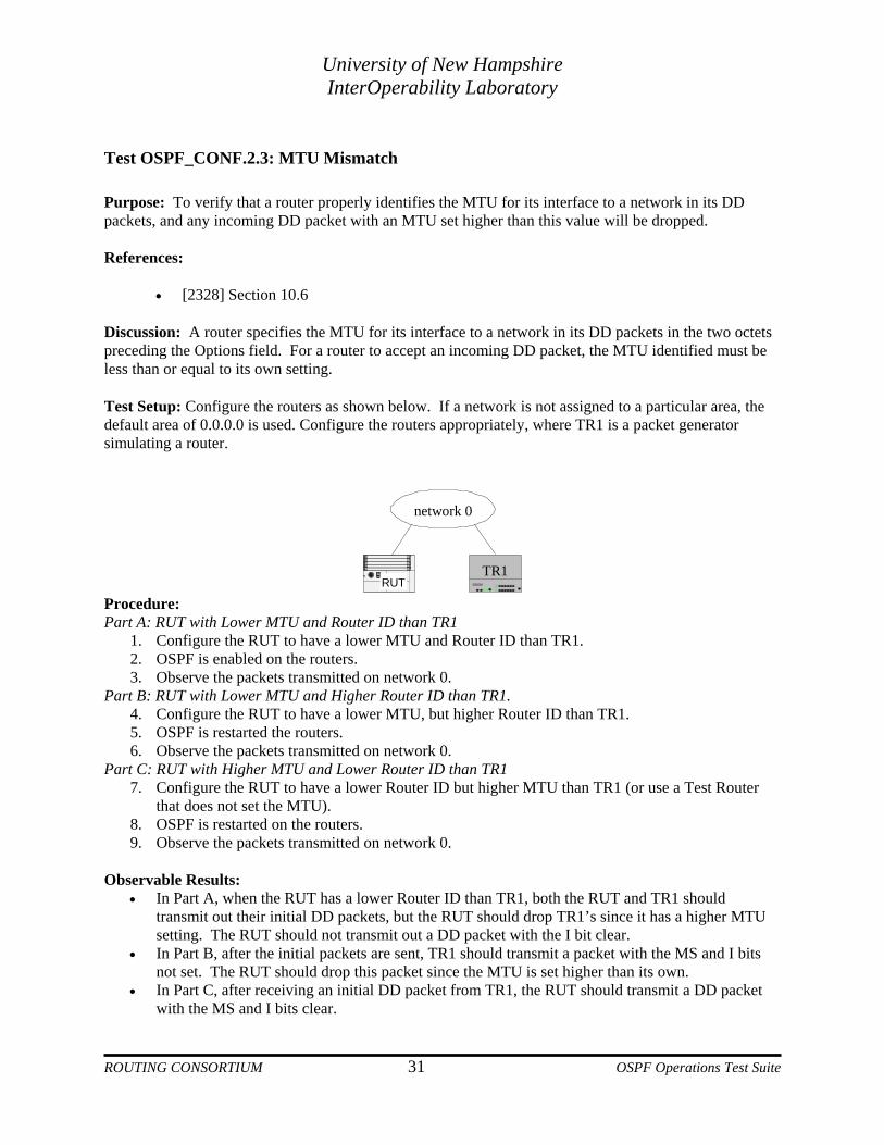
• [2328] Section 10.6 Discussion: A router specifies the MTU for its interface to a network in its DD packets in the two octets preceding the Options field. For a router to accept an incoming DD packet, the MTU identified must be less than or equal to its own setting. Test Setup: Configure the routers as shown below. If a network is not assigned to a particular area, the default area of 0.0.0.0 is used. Configure the routers appropriately, where TR1 is a packet generator simulating a router.
network 0
RUTTR1
Procedure: Part A: RUT with Lower MTU and Router ID than TR1
1. Configure the RUT to have a lower MTU and Router ID than TR1. 2. OSPF is enabled on the routers. 3. Observe the packets transmitted on network 0.
Part B: RUT with Lower MTU and Higher Router ID than TR1. 4. Configure the RUT to have a lower MTU, but higher Router ID than TR1. 5. OSPF is restarted the routers. 6. Observe the packets transmitted on network 0.
Part C: RUT with Higher MTU and Lower Router ID than TR1 7. Configure the RUT to have a lower Router ID but higher MTU than TR1 (or use a Test Router
that does not set the MTU). 8. OSPF is restarted on the routers. 9. Observe the packets transmitted on network 0.
Observable Results:
• In Part A, when the RUT has a lower Router ID than TR1, both the RUT and TR1 should transmit out their initial DD packets, but the RUT should drop TR1’s since it has a higher MTU setting. The RUT should not transmit out a DD packet with the I bit clear.
• In Part B, after the initial packets are sent, TR1 should transmit a packet with the MS and I bits not set. The RUT should drop this packet since the MTU is set higher than its own.
• In Part C, after receiving an initial DD packet from TR1, the RUT should transmit a DD packet with the MS and I bits clear.
ROUTING CONSORTIUM 31 OSPF Operations Test Suite
University of New Hampshire InterOperability Laboratory
Possible Problems: None.
ROUTING CONSORTIUM 32 OSPF Operations Test Suite

University of New Hampshire InterOperability Laboratory
Test OSPF_CONF.2.4: Master Negotiation Purpose: To verify that the Master/Slave is properly negotiated. References: [2328] Section 10.6 [1583] Section 10.6 Discussion: To provide for the effective sharing of summary information during DD process, one router is designated Master, and the other Slave. After both routers transmit out their initial DD packets, the router with the lower Router ID designates itself the Slave. It should transmit out a DD packet with the Initial (I) and Master (MS) bits clear, and with the sequence number of the initial packet sent by the Master router. The Master should then transmit out a DD packet with the MS bit set (I bit clear) and a sequence 1 higher than that just sent by the Slave. Test Setup: Configure the routers as shown below. If a network is not assigned to a particular area, the default area of 0.0.0.0 is used.
network 0
RUTTR1
Procedure: Part A: RUT with Lower Router ID
1. Configure the RUT with a lower Router ID than TR1’s Router ID. 2. OSPF is enabled on the routers. 3. Wait until their databases are synchronized; observe the packets transmitted on network 0.
Part B: RUT with Higher Router ID 4. Configure the RUT with a higher Router ID than TR1’s Router ID. 5. OSFP is restarted on the routers. 6. Wait until the databases are synchronized; observe the packets transmitted on network 0.
Observable Results:
• In Part A, after the RUT receives the initial DD packet from TR1, it should transmit out DD packets with the I and MS bits clear. The sequence number is set to that specified in TR1's initial DD packet.
• In Part B, the RUT should receive a DD packet from TR1 with the I and MS bits clear and the sequence number equal to its own sequence number. The RUT should transmit out a DD packet with the I bit clear, the MS bit set and the sequence number incremented by one.
Possible Problems: None.
ROUTING CONSORTIUM 33 OSPF Operations Test Suite

University of New Hampshire InterOperability Laboratory
Test OSPF_CONF.2.5: Self-Originated LSA Processing Purpose: To verify that a router advances its LS sequence numbers when it finds that there are old LSAs originated by itself in another router's database. References:
• [2328] Section 13.4 • [1583] Section 13.4
Discussion: An incoming LSA is considered self-originated when either 1) the LSA’s Advertising Router ID is equal to the router’s own Router ID or 2) the LSA is a network-LSA with Link State ID equal to one of the router’s own IP interface addresses. If a received self-originated LSA is newer (e.g. has a higher sequence number) than the instance the router has in its own database, it indicates that there are LSA’s in the routing domain that were originated by the router before the last time it was restarted. To remove these old LSA’s from the domain, the router must advance the LS sequence number of the LSA in its database to be one greater than that of the received LSA, and originate a new instance of the LSA. Test Setup: Configure the routers as shown below. If a network is not assigned to a particular area, the default area of 0.0.0.0 is used. Configure the routers appropriately, where TR1 is a packet generator simulating a router
network 0
RUTTR1
Procedure: Part A: LSA with Higher SeqNumber
1. OSPF is enabled on the routers so that the RUT becomes DR. 2. After the RUT and TR1’s database synchronize, restart OSPF on the RUT. 3. When TR1 and the RUT resynchronize their databases, TR1 lists the RUT’s old router-LSA in
one its DD packets. 4. Observe the packets transmitted on network 0.
Part B: LSA No Longer Being Advertised 5. TR1 also lists the RUT’s old network-LSA in one of its DD packets. 6. Observe the packets transmitted on network 0.
Observable Results:
• In Part A, the RUT should request its old router-LSA. After TR1 transmits this old router-LSA, the RUT should transmit a new router-LSA with a higher sequence number.
• In Part B, the RUT should request its old network-LSA. After TR1 transmits this old network-LSA, the RUT should transmit an LS Update containing this LSA with MaxAge.
Possible Problems: None.
ROUTING CONSORTIUM 34 OSPF Operations Test Suite

University of New Hampshire InterOperability Laboratory
Test OSPF_CONF.2.6: Receiving Old LSAs Purpose: To verify that a router discards an LSA that is older than the database copy if it supports only RFC 1583. If the router supports RFC 2328, a router should transmit its current database copy of the LSA unicast back to a neighbor from whom it receives an LSA that is older than the database copy. References:
• [2328] Section 13 • [1583] Section 13
Discussion: RFC 2328 (RFC 2178 or newer) – If a router (A) receives an LSA that is older than its database copy, the router must transmit its database copy unicast to the originating neighbor (B). This should replace the older instance with the newer instance of the LSA in the router B's link state database. Router A should not place Router B on its link state retransmission list, and should not acknowledge the older LSA originally sent by Router B. Test Setup: Configure the routers as shown below. If a network is not assigned to a particular area, the default area of 0.0.0.0 is used. Configure the routers appropriately, where TR1 is a packet generator simulating a router.
network 0
RUTTR1
Procedure: Part A: RUT Supports RFC 2328
1. OSPF is enabled on the routers. Wait for their databases to synchronize. 2. TR1 transmits a router-LSA for itself with sequence number 0x70000001. 3. TR1 transmits a router-LSA for itself with sequence number 0x8FFFFFFE after more than
minLSInterval. 4. Observe the packets transmitted on network 0.
Observable Results:
• In Part A, if the RUT supports RFC 2328, upon receipt of the router-LSA with sequence number 0x8FFFFFFE, it should transmit the sequence number 0x70000001 instance of the router-LSA unicast to TR1. It should not acknowledge the older (0x8FFFFFFE) LSA, and should not place TR1 on its retransmission list when it transmits the newer LSA (0x70000001).
Possible Problems: The RUT may support RFC 1583.
ROUTING CONSORTIUM 35 OSPF Operations Test Suite

University of New Hampshire InterOperability Laboratory
Test OSPF_CONF.2.7: Neighbor in Lower State than Exchange Purpose: To verify that a router discards an LSA or LS Request received from a neighbor in a lesser state than Exchange. References:
• [2328] Sections 10.7 and 13 • [1583] Sections 10.7 and 13
Discussion: A router should accept a Link State Advertisement or Link State Request packet only from a neighbor in state Exchange, Loading, or Full. Test Setup: Configure the routers as shown below. If a network is not assigned to a particular area, the default area of 0.0.0.0 is used. Configure the routers appropriately, where TR1 is a packet generator simulating a router.
network 0
RUTTR1
Procedure: Part A: LSA Sent in Lesser State than Exchange
1. OSPF is enabled on the routers. Wait for their databases to synchronize. 2. TR1 transmits Hello packets listing the RUT as a neighbor, but no DD packets (so the RUT
cannot go beyond state ExStart). 3. After receiving an initial DD packet from the RUT, TR1 transmits a Link State Update unicast to
the RUT. 4. Observe the packets transmitted on network 0.
Part B: LSRequest Sent in Lesser State than Exchange 5. TR1 transmits a Link State Request packet. 6. Observe the packets transmitted on network 0.
Observable Results:
• In Part A, the RUT should not acknowledge the Link State Update from TR1, and it should not add the LSA to its link state database.
• In Part B, the RUT should not respond to the Link State Request from TR1. Possible Problems: None.
ROUTING CONSORTIUM 36 OSPF Operations Test Suite

University of New Hampshire InterOperability Laboratory
Test OSPF_CONF.2.8: DD Retransmission Purpose: To verify that a router properly retransmits DD packets. References:
• [2328] Section 10.8 • [1583] Section 10.8
Discussion:
• When a router is Slave during the DD Exchange process, it should only retransmit a non-initial DD packet when it receives a duplicate DD packet from the Master. It should also retain its final DD packet for RouterDeadInterval after entering state Loading.
• When a router is Master during the DD Exchange process, it should retransmit its most recent DD packet when RxmtInterval has elapsed without receiving the next DD packet from the Slave.
Test Setup: Configure the routers as shown below. If a network is not assigned to a particular area, the default area of 0.0.0.0 is used. Configure the routers appropriately, where TR1 is a packet generator simulating a router. TR1 should have a higher Router ID than the RUT.
network 0
RUTTR1
Procedure: Part A: Slave does not Receive DD Packet from Master
1. OSPF is enabled on the routers. 2. TR1 transmits only an initial DD packet. 3. Observe the packets transmitted on network 0.
Part B: Slave Receives Duplicate DD Packet from Master 4. OSPF is restarted the routers. 5. TR1 transmits enough LSA’s to fill at least four DD packets. 6. TR1 is shut down for RouterDeadInterval. 7. OSPF is restarted on TR1. 8. During the DD Exchange process, after the RUT transmits its third DD packet, TR1 should
retransmit its previous packet. 9. Observe the packets transmitted on network 0.
Part C: Master Retransmits DD Packet 10. TR1 should have a lower Router ID than the RUT. 11. OSPF is restarted on the routers. 12. After the DD Exchange process starts, TR1 transmits only its first non-initial DD packet to the
RUT.
13. Observe the packets transmitted on network 0. Observable Results:
ROUTING CONSORTIUM 37 OSPF Operations Test Suite

University of New Hampshire InterOperability Laboratory
• In Part A, the RUT should transmit a non-initial DD packet after receiving TR1’s initial packet.
• B, the RUT should retransmit its third DD packet RxmtInterval after receiving the
• uld retransmit its last DD packet to TR1 every RxmtInterval seconds.
ossible Problems: None.
The RUT should not retransmit this packet as a result of not receiving another DD packet from TR1. In Partduplicate DD packet. In Part C, the RUT sho
P
ROUTING CONSORTIUM 38 OSPF Operations Test Suite
University of New Hampshire InterOperability Laboratory
Test OSPF_CONF.2.9: Event Sequence Number Mismatch Purpose: To verify that a router transitions to state ExStart when Event SeqNumberMismatch occurs. References:
• [2328] Sections 10.6 and 10.8 • [1583] Sections 10.6 and 10.8
Discussion: Event SeqNumberMismatch should always cause the neighbor state to revert to ExStart. While in state Exchange or greater, event SeqNumberMismatch should occur when:
• The Options field of a neighbor's DD packet is set differently from the neighbor's previous DD packet.
• A neighbor's DD packet unexpectedly has the I bit set. • A neighbor's DD packet has an unexpected sequence number. • The MS bit of a neighbor's DD packet is set inconsistently with the state of the connection. • A neighbor's DD packet contains an LSA header with an unknown LS type. • A neighbor's packet contains an LSA header for an AS-external-LSA within a stub area. • The router was the Slave during the DD Exchange process and it receives a DD packet from the
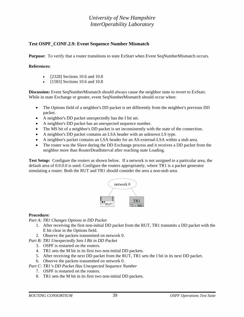
neighbor more than RouterDeadInterval after reaching state Loading. Test Setup: Configure the routers as shown below. If a network is not assigned to a particular area, the default area of 0.0.0.0 is used. Configure the routers appropriately, where TR1 is a packet generator simulating a router. Both the RUT and TR1 should consider the area a non-stub area.
network 0
RUTTR1
Procedure: Part A: TR1 Changes Options in DD Packet
1. After receiving the first non-initial DD packet from the RUT, TR1 transmits a DD packet with the E bit clear in the Options field.
2. Observe the packets transmitted on network 0. Part B: TR1 Unexpectedly Sets I Bit in DD Packet
3. OSPF is restarted on the routers. 4. TR1 sets the M bit in its first two non-initial DD packets. 5. After receiving the next DD packet from the RUT, TR1 sets the I bit in its next DD packet. 6. Observe the packets transmitted on network 0.
Part C: TR1’s DD Packet Has Unexpected Sequence Number 7. OSPF is restarted on the routers. 8. TR1 sets the M bit in its first two non-initial DD packets.
ROUTING CONSORTIUM 39 OSPF Operations Test Suite

University of New Hampshire InterOperability Laboratory
9. After receiving the next DD packet from the RUT, TR1 transmits a DD packet with a sequence number higher than expected.
10. Observe the packets transmitted on network 0. Part D: TR1’s DD Packet Has Unexpected Sequence Number
11. OSPF is restarted on the routers. 12. TR1 sets the M bit in its first two non-initial DD packets. 13. After receiving the next DD packet from the RUT, TR1 transmits a DD packet with a sequence
number lower than expected. 14. Observe the packets transmitted on network 0.
Part E: TR1 has Inconsistent MS Bit in DD Packet 15. TR1 has a higher Router ID than the RUT. 16. OSPF is restarted on the routers. 17. After the RUT transmits its first non-initial packet, TR1 transmits its next packet with the MS bit
clear. 18. Observe the packets transmitted on network 0.
Part F: RUT receives DD Packet from Neighbor RouterDeadInterval after Reaching State Loading 19. OSPF is restarted on the routers. 20. After more than RouterDeadInterval after the DD Exchange process is complete, TR1 transmits a
DD packet to the RUT, with everything set appropriately as for what would have been its next DD packet, if necessary.
21. Observe the packets transmitted on network 0. Part G: TR Transmits DD Packet with Unknown LS Type
22. OSPF is restarted on the routers. 23. After the RUT transmits its first non-initial DD packet, TR1 transmits its next packet containing
an LSA Header of an unknown LS type. 24. Observe the packets transmitted on network 0.
Part H: TR Transmits DD Pack Containing an AS-External LSA header to a Stub Area 25. Both the RUT and TR1 should consider the area to be in a stub area. 26. OSPF is restarted on the routers. 27. TR1’s first non-initial DD packet includes an LSA Header for an AS-external-LSA. 28. Observe the packets transmitted on network 0.
Observable Results:
• In Part A, the RUT should transition to state ExStart and transmit a DD packet with the I, MS and M bits set when it receives TR1’s DD packet with different Options.
• In Part B, the RUT should transition to state ExStart after TR1 transmits its DD packet with the I bit unexpectedly set.
• In both Parts C and D, The RUT should transition to state ExStart after receiving the DD packet with an unexpected sequence number.
• In Part E, the RUT should transition to state ExStart after receiving the DD packet with the MS bit clear.
• In Part F, the RUT should transition to state ExStart when it receives TR1’s DD packet more than RouterDeadInterval after reaching state Loading.
• In Part G, the RUT should transition to state ExStart after receiving the DD packet containing an LSA Header of unknown type.
• In Part H, the RUT should transition to state ExStart after receiving TR1's DD packet containing an AS-external-LSA Header.
ROUTING CONSORTIUM 40 OSPF Operations Test Suite

University of New Hampshire InterOperability Laboratory
Possible Problems: None.
ROUTING CONSORTIUM 41 OSPF Operations Test Suite
University of New Hampshire InterOperability Laboratory
Test OSPF_CONF.2.10: Basic Flooding Purpose: To verify that a router properly floods non-AS-external-LSAs throughout the area but not outside of it. References:
• [2328] Section 13 • [1583] Section 13
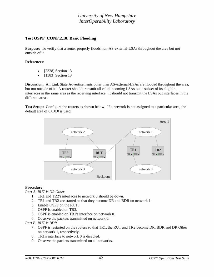
Discussion: All Link State Advertisements other than AS-external-LSAs are flooded throughout the area, but not outside of it. A router should transmit all valid incoming LSAs out a subset of its eligible interfaces in the same area as the receiving interface. It should not transmit the LSAs out interfaces in the different areas. Test Setup: Configure the routers as shown below. If a network is not assigned to a particular area, the default area of 0.0.0.0 is used.
Area 1
Backbone
network 0
network 1network 2
network 3
RUTTR1 TR2
TR3
Procedure: Part A: RUT is DR Other
1. TR1 and TR2's interfaces to network 0 should be down. 2. TR1 and TR2 are started so that they become DR and BDR on network 1. 3. Enable OSPF on the RUT. 4. OSPF is enabled on TR3. 5. OSPF is enabled on TR1's interface on network 0. 6. Observe the packets transmitted on network 0.
Part B: RUT is BDR 7. OSPF is restarted on the routers so that TR1, the RUT and TR2 become DR, BDR and DR Other
on network 1, respectively. 8. TR1's interface to network 0 is disabled. 9. Observe the packets transmitted on all networks.
ROUTING CONSORTIUM 42 OSPF Operations Test Suite

University of New Hampshire InterOperability Laboratory
Part C: RUT is DR
10. OSPF is enabled on the routers so that the RUT, TR1 and TR2 become DR, BDR and DR Other on network 1, respectively.
11. TR1's interface on network 0 is enabled. 12. Observe the packets transmitted on network 0.
Observable Results:
• In Parts A, B and C, after TR1 transmits its new router-LSA to network 1, the RUT should flood it to network 2, but not network 3
Possible Problems: None.
ROUTING CONSORTIUM 43 OSPF Operations Test Suite

University of New Hampshire InterOperability Laboratory
Test OSPF_CONF.2.11: Flooding AS-External LSAs Purpose: To verify that a router properly floods AS-external-LSAs throughout the OSPF AS. References:
• [2328] Section 13 • [1583] Section 13
Discussion: While non-AS-external-LSAs are flooded only throughout a single area, AS-external-LSAs are flooded throughout the OSPF Autonomous System, except for stub areas and virtual links. Test Setup: Configure the routers as shown below. If a network is not assigned to a particular area, the default area of 0.0.0.0 is used.
Area 2 (stub)Area 1
network 2
RUTTR3
network 3
network 0
network 1
TR1
TR2
Backbone
virtual link
Procedure: Part A: RUT is DR Other
1. TR1 is an ASBR. 2. TR1 has an external link configured. 3. Configure a virtual link between the RUT and TR3 in area 1. 4. OSPF is enabled on TR1 and TR2 so that they become DR and BDR on network 0. 5. OSPF is enabled on all the other routers. 6. TR1’s cost on the external link should change. 7. Observe the packets transmitted on network 0.
Part B: RUT is BDR 8. OSPF is restarted on the routers so that TR1, the RUT and TR2 become DR, BDR and DR Other
on network 0, respectively. 9. TR1’s cost on the external link should change. 10. Observe the packets transmitted on network 0.
ROUTING CONSORTIUM 44 OSPF Operations Test Suite
University of New Hampshire InterOperability Laboratory
Part C: RUT is DR 11. OSPF is restarted on the routers so that the RUT, TR1 and TR2 become DR, BDR and DR Other
on network 0, respectively. 12. TR1’s cost on the external link should change. 13. Observe the packets transmitted on network 0.
Observable Results:
• In Parts A, B and C, after TR1 transmits its new AS-external-LSA to network 0, the RUT should flood it to network 2 and network 3, but not network 1 or the virtual link.
Possible Problems: None.
ROUTING CONSORTIUM 45 OSPF Operations Test Suite

University of New Hampshire InterOperability Laboratory
Test OSPF_CONF.2.12: Flooding LSA Acknowledgements Purpose: To verify that a router properly floods or acknowledges an incoming LSA. References:
• [2328] Section 13.5 • [1583] Section 13.5
Discussion: An LSA should be acknowledged properly according to the circumstances surrounding the receipt of the advertisement.
• If a router is DR and receives a new LSA from a DR Other, it should flood the LSA back out the receiving interface to the AllSPFRouters address (224.0.0.5). The flooded LSA is also considered an implied acknowledgement, so no explicit acknowledgement should be sent.
• If a router is DR and receives a new LSA from the BDR, it should transmit a delayed (multicast) acknowledgement.
• If a router is the BDR and receives a new LSA from a DR Other, it does nothing. Later, the router will receive the LSA again from the DR and it should transmit a delayed acknowledgement to the AllSPFRouters address.
• If a router is the BDR and receives a new LSA from the DR, it should transmit a delayed acknowledgement to the AllSPFRouters address.
• If a router is a DR Other and receives a new LSA from the DR or BDR, it should transmit a delayed acknowledgement to the AllDRouters address (224.0.0.6).
• If a router is a DR Other and it originates a new LSA, the DR will flood it back to the AllSPFRouters address. The router should not transmit an acknowledgement for this flooded LSA.
• The fixed interval between a router’s delayed transmissions must be short (less than RxmtInterval) or needless retransmissions will ensue.
Test Setup: Configure the routers as shown below. If a network is not assigned to a particular area, the default area of 0.0.0.0 is used.
network 0
RUTTR1 TR2
network 2 network 1
Observable Results: Part A: DR Receives LSA from DR Other
1. TR1 and TR2's interfaces to network 1 are disabled.
ROUTING CONSORTIUM 46 OSPF Operations Test Suite
University of New Hampshire InterOperability Laboratory
2. OSPF is enabled on the routers so that the RUT, TR1 and TR2 become DR, BDR and DR Other on network 0, respectively.
3. TR2's interface to network 1 is enabled. 4. Observe the packets transmitted on all networks.
Part B: DR Receives LSA from BDR 5. TR2's interface to network 1 is disabled. 6. TR1's interface to network 1 is enabled at least ten seconds after TR2’s interface to network 1 is
disabled (so the packets are separated). 7. Observe the packets transmitted on all networks.
Part C: BDR Receives LSA from DR Other 8. OSPF is restarted on the routers so that TR2, the RUT and TR1 become DR, BDR and DR Other
on network 0, respectively. 9. TR2's interface to network 0 is unplugged. 10. TR1's interface to network 1 is disabled. 11. Observe the packets transmitted on all networks.
Part D: BDR Receives LSA from BDR 12. TR2’s interface to network 0 is plugged in. 13. OSPF is restarted on the routers so that TR2, the RUT, and TR1 become DR, BDR and DR Other
on network 0, respectively. 14. TR2's interface to network 1 is enabled. 15. Observe the packets transmitted on all networks.
Part E: DR Other Receives LSA from DR and BDR 16. OSPF is restarted on the routers so that TR1, TR2 and the RUT become DR, BDR and DR Other
on network 0, respectively. 17. TR2's interface to network 1 is disabled. 18. Observe the packets transmitted on all networks.
Part F: DR Other Originates LSA 19. Disable the RUT's interface to network 2. 20. Observe the packets transmitted on all networks.
Observable Results:
• In Part A, after TR2 transmits its new router-LSA to the AllDRouters address on network 0, the RUT should flood it back to the AllSPFRouters address on network 0. It should not transmit an explicit acknowledgement.
• In Part B, after TR1 transmits its new router-LSA to the AllSPFRouters address on network 0, the RUT should not flood the LSA. It should transmit an acknowledgement to the AllSPFRouters address.
• In Part C, after TR1 transmits its new router-LSA to the AllDRouters address on network 0, the RUT should wait RxmtInterval and then retransmit the LSA to TR2.
• In Part D, after TR2 transmits its new router-LSA to the AllSPFRouters address, the RUT should transmit a delayed Acknowledgement to the AllSPFRouters address.
• In Part E, after TR2 transmits its new router-LSA to the AllSPFRouters address, the RUT should transmit a delayed Acknowledgement to the AllDRouters address.
• In Part F, after TR1 floods the RUT's new router-LSA to network 0, the RUT should not transmit an Acknowledgement.
Possible Problems: None.
ROUTING CONSORTIUM 47 OSPF Operations Test Suite
University of New Hampshire InterOperability Laboratory
Test OSPF_CONF.2.13: LSA Retransmission Purpose: To verify that a router properly places all routers that it is adjacent with on its retransmission list when appropriate. References:
• [2328] Section 13.6 • [1583] Section 13.6
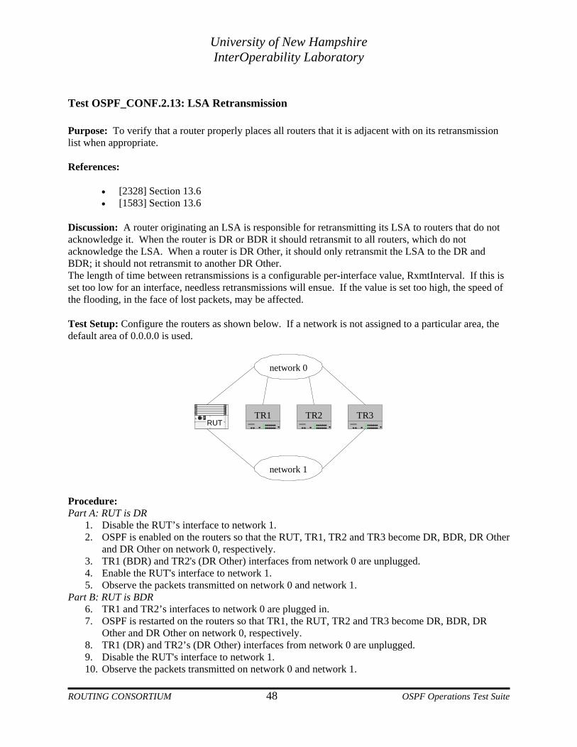
Discussion: A router originating an LSA is responsible for retransmitting its LSA to routers that do not acknowledge it. When the router is DR or BDR it should retransmit to all routers, which do not acknowledge the LSA. When a router is DR Other, it should only retransmit the LSA to the DR and BDR; it should not retransmit to another DR Other. The length of time between retransmissions is a configurable per-interface value, RxmtInterval. If this is set too low for an interface, needless retransmissions will ensue. If the value is set too high, the speed of the flooding, in the face of lost packets, may be affected. Test Setup: Configure the routers as shown below. If a network is not assigned to a particular area, the default area of 0.0.0.0 is used.
network 0
network 1
RUTTR1 TR2 TR3
Procedure: Part A: RUT is DR
1. Disable the RUT’s interface to network 1. 2. OSPF is enabled on the routers so that the RUT, TR1, TR2 and TR3 become DR, BDR, DR Other
and DR Other on network 0, respectively. 3. TR1 (BDR) and TR2's (DR Other) interfaces from network 0 are unplugged. 4. Enable the RUT's interface to network 1. 5. Observe the packets transmitted on network 0 and network 1.
Part B: RUT is BDR 6. TR1 and TR2’s interfaces to network 0 are plugged in. 7. OSPF is restarted on the routers so that TR1, the RUT, TR2 and TR3 become DR, BDR, DR
Other and DR Other on network 0, respectively. 8. TR1 (DR) and TR2’s (DR Other) interfaces from network 0 are unplugged. 9. Disable the RUT's interface to network 1. 10. Observe the packets transmitted on network 0 and network 1.
ROUTING CONSORTIUM 48 OSPF Operations Test Suite

University of New Hampshire InterOperability Laboratory
Parerfaces to network 0 are plugged in.
T and TR2 become DR, BDR, DR
13. work 0 are unplugged.
rk 0 and network 1. Par
erfaces to network 0 are plugged in. T and TR2 become DR, BDR, DR
18. twork 0 are unplugged.
k 0 and network 1. Par
ission frequency on network 0.
bservable Results: B, the RUT should update its router-LSA with a link to network 1. It should only
• he RUT enables its interface to network 1, it should retransmit the
• ables its interface to network 1, it should retransmit the LSA to TR3,
• UT should retransmit only a single packet to a neighbor every RxmtInterval.
ossible Problems: None.
t C: RUT is DR Other 11. TR1 and TR2’s int12. OSPF is restarted on the routers so that TR1, TR3, the RU
Other and DR Other on network 0, respectively. TR1 (DR) and TR2's (DR Other) interfaces to net
14. Enable the RUT's interface to network 1. 15. Observe the packets transmitted on netwot D: RUT is DR Other 16. TR1 and TR2’s int17. OSPF is restarted on the routers so that TR1, TR3, the RU
Other and DR Other on network 0, respectively. TR3 (BDR) and TR2's (DR Other) interfaces to ne
19. Disable the RUT's interface to network 1. 20. Observe the packets transmitted on networt E: Retransmission Frequency 21. Observe the RUT’s retransm
O• In Parts A and
receive an acknowledgement from TR3. Five seconds after it sent the router-LSA, it should retransmit to TR1 and TR2. In Part C, five seconds after tLSA to TR1, but not TR2. In Part D, after the RUT disbut not TR2. In Part E, the R
P
ROUTING CONSORTIUM 49 OSPF Operations Test Suite

University of New Hampshire InterOperability Laboratory
Test OSPF_CONF.2.14: LSA Flooding Guarantee Purpose: To verify that a router properly places all routers that it is adjacent with on its retransmission list when appropriate. References:
• [2328] Section 13.6 • [1583] Section 13.6
Discussion: An OSPF router should retransmit a received LSA to adjacent routers that do not acknowledge receiving the LSA. This ensures that the link state database for every router in an area is the same. When a router is DR or BDR on a network and receives an LSA, it should retransmit the LSA to all routers that do not acknowledge the LSA. When a router is DR Other on a network, it should only retransmit the LSA if either the DR or the BDR does not acknowledge receiving the LSA. Test Setup: Configure the routers as shown below. If a network is not assigned to a particular area, the default area of 0.0.0.0 is used.
network 0
network 1
RUTTR1 TR2 TR3
Procedure: Part A: RUT is DR
1. TR3's interface to network 1 is disabled. 2. OSPF is enabled on the routers so that the RUT, TR3, TR2 and TR1 become DR, BDR, DR Other
and DR Other on network 0, respectively. 3. TR1 (DR Other) and TR2's (DR Other) interfaces from network 0 are unplugged. 4. TR3's (BDR) interface to network 1 is enabled. 5. Observe the packets transmitted on network 0 and network 1.
Part B: RUT is DR 6. TR1 and TR2’s interfaces to network 0 are plugged in. 7. OSPF is restarted on the routers so that the RUT, TR1, TR2 and TR3 become DR, BDR, DR
Other and DR Other on network 0, respectively. 8. TR1's (BDR) interface to network 0 is unplugged. 9. TR3's (DR Other) interface to network 1 is disabled. 10. Observe the packets transmitted on network 0 and network 1.
ROUTING CONSORTIUM 50 OSPF Operations Test Suite
University of New Hampshire InterOperability Laboratory
Part C: RUT is BDR 11. TR1’s interface to network 0 is plugged in. 12. OSPF is restarted on the routers so that TR3, the RUT, TR1 and TR2 become DR, BDR, DR
Other and DR Other on network 0, respectively. 13. TR1 (DR Other) and TR2's (DR Other) interfaces to network 0 are unplugged. 14. TR3's (DR) interface to network 1 is enabled. 15. Observe the packets transmitted on network 0 and network 1.
Part D: RUT is BDR 16. TR1 and TR2’s interfaces to network 0 are plugged in. 17. OSPF is restarted on the routers so that TR1, the RUT, TR2 and TR3 become DR, BDR, DR
Other and DR Other on network 0, respectively. 18. TR1's (DR) interface to network 0 is unplugged. 19. TR3's (DR Other) interface to network 1 is disabled. 20. Observe the packets transmitted on network 0 and network 1.
Part E: RUT is DR Other 21. TR1’s interface to network 0 is plugged in. 22. OSPF is restarted on the routers so that TR3, TR2, TR1 and the RUT become DR, BDR, DR
Other and DR Other on network 0, respectively. 23. TR1 (DR Other) and TR2's (BDR) interface to network 0 are unplugged. 24. TR3's (DR) interface to network 1 is enabled. 25. Observe the packets transmitted on network 0 and network 1.
Part F: RUT is DR Other 26. TR1 and TR2’s interfaces to network 0 are plugged in. 27. OSPF is restarted on the routers so that TR2, TR3, TR1 and the RUT become DR, BDR, DR
Other and DR Other on network 0, respectively. 28. TR1 (DR Other) and TR2's (DR) interfaces to network 0 are unplugged. 29. TR3's (BDR) interface to network 1 is disabled. 30. Observe the packets transmitted on network 0 and network 1.
Observable Results:
• In Part A, after TR3 transmits its new router-LSA to network 0, TR1 and TR2 will not acknowledge the LSA. RxmtInterval after the first transmission, the RUT should begin retransmitting this LSA unicast to both TR1 and TR2.
• In Part B, after TR3 transmits its new router-LSA to network 0, the RUT should flood the LSA to the network. When TR1 does not transmit an acknowledgement, the RUT should retransmit the LSA unicast to TR1 every RxmtInterval seconds.
• In Part C, after TR3 transmits its new router-LSA to network 0, the RUT should retransmit TR3's router-LSA unicast to both TR1 and TR2 every RxmtInterval seconds.
• In Part D, after TR3 transmits its new router-LSA to network 0, TR1 will not be able to flood the LSA since it is unplugged. Therefore, the RUT should retransmit the LSA to TR1 every RxmtInterval.
• In Parts E and F, the RUT should retransmit TR3's new router-LSA to TR2 (not TR1) every RxmtInterval.
Possible Problems: None.
ROUTING CONSORTIUM 51 OSPF Operations Test Suite

University of New Hampshire InterOperability Laboratory
Test OSPF_CONF.2.15: LSA Multicast Purpose: To verify that a router transmits its LS Update packets to the correct multicast address depending on the state of its interface. References:
• [2328] Section 13.3 • [1583] Section 13.3
Discussion: An OSPF router should transmit its LS Update packets to one of two multicast addresses depending on the state of its interface on the network. A DR or BDR should use the AllSPFRouters address (224.0.0.5). A DR Other should use the AllDRouters address (224.0.0.6). Test Setup: Configure the routers as shown below. If a network is not assigned to a particular area, the default area of 0.0.0.0 is used.
network 1
RUTTR1
network 0
Purpose: Part A: RUT Transmits LSAs to AllSPFRouters Address
1. Disable the RUT's interface to network 0. 2. Start the routers so that the RUT becomes DR on network 1. 3. Enable the RUT's interface to network 0. 4. Observe the packets transmitted on network 0 and network 1.
Part B: RUT Transmits LSAs to AllSPFRouters Address 5. Restart the routers so that the RUT becomes BDR on network 1. 6. Disable the RUT's interface to network 0. 7. Observe the packets transmitted on network 0 and network 1.
Part C: AllSPFRouters Hardware Address 8. Observe the hardware address of the AllSPFRouters address in the RUT’s LS Update.
Part D: RUT Transmits LSAs to AllDRouters Address 9. Configure the RUT to have priority 0 on network 1. 10. Restart the routers (TR1 should become DR). 11. Enable the RUT's interface to network 0. 12. Observe the packets transmitted on network 0 and network 1.
Part E: AllDRouters Hardware Address
13. Observe the hardware address of the AllDRouters address in the RUT’s LS Update.
ROUTING CONSORTIUM 52 OSPF Operations Test Suite

University of New Hampshire InterOperability Laboratory
Observable Results:
B, the RUT should transmit its new router-LSAs in Link State Update packets to
• lgorithmically mapped to the 01:00:5e:00:00:05
• should transmit its new router-LSA in a Link State Update packet to the
• is algorithmically mapped to the 01:00:5e:00:00:06 hardware
ossible Problems: None.
• In Parts A andthe AllSPFRouters address (224.0.0.5). In Part C, the AllSPFRouters address is ahardware address. In Part D, the RUTAllDRouters address (224.0.0.6). In Part E, the AllDRouters addressaddress.
P
ROUTING CONSORTIUM 53 OSPF Operations Test Suite
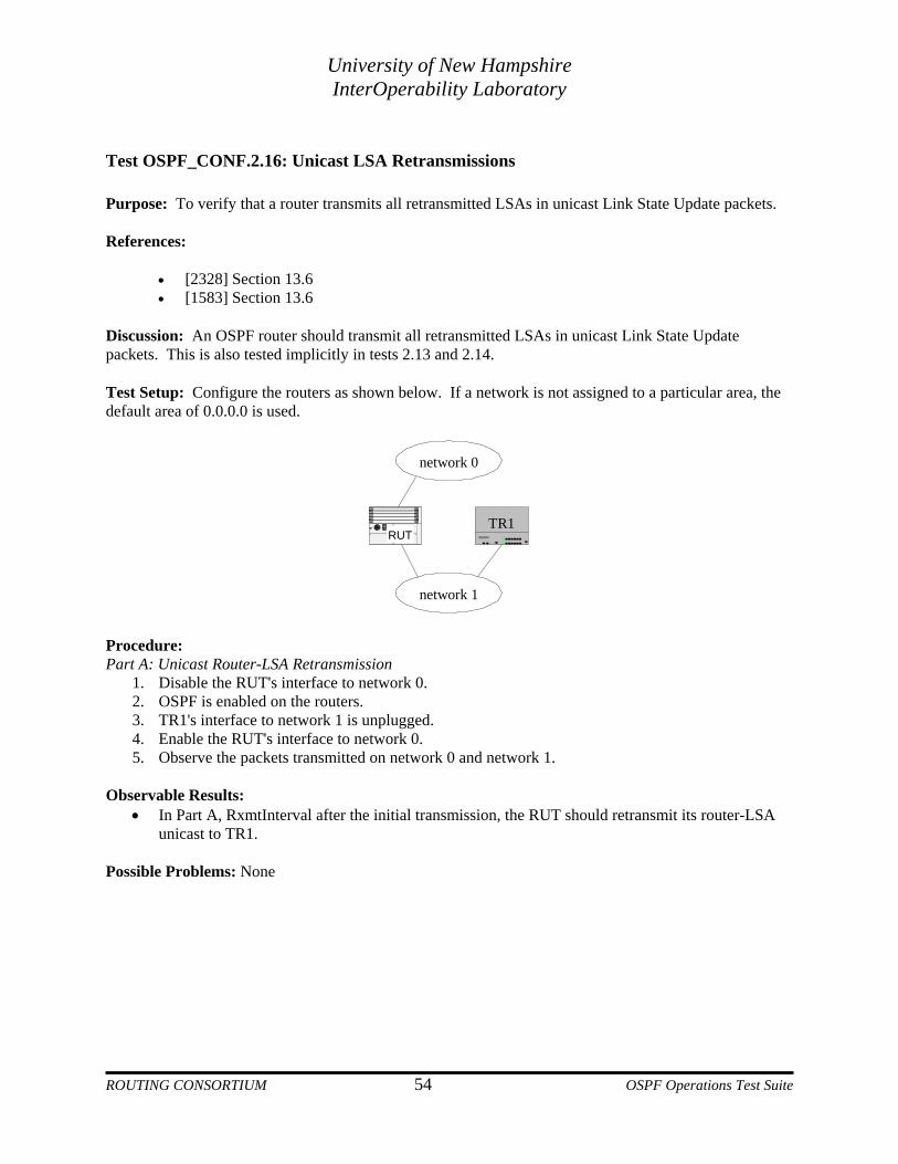
University of New Hampshire InterOperability Laboratory
Test OSPF_CONF.2.16: Unicast LSA Retransmissions Purpose: To verify that a router transmits all retransmitted LSAs in unicast Link State Update packets. References:
• [2328] Section 13.6 • [1583] Section 13.6
Discussion: An OSPF router should transmit all retransmitted LSAs in unicast Link State Update packets. This is also tested implicitly in tests 2.13 and 2.14. Test Setup: Configure the routers as shown below. If a network is not assigned to a particular area, the default area of 0.0.0.0 is used.
network 1
RUTTR1
network 0
Procedure: Part A: Unicast Router-LSA Retransmission
1. Disable the RUT's interface to network 0. 2. OSPF is enabled on the routers. 3. TR1's interface to network 1 is unplugged. 4. Enable the RUT's interface to network 0. 5. Observe the packets transmitted on network 0 and network 1.
Observable Results:
• In Part A, RxmtInterval after the initial transmission, the RUT should retransmit its router-LSA unicast to TR1.
Possible Problems: None
ROUTING CONSORTIUM 54 OSPF Operations Test Suite
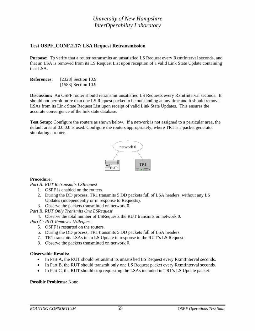
University of New Hampshire InterOperability Laboratory
Test OSPF_CONF.2.17: LSA Request Retransmission Purpose: To verify that a router retransmits an unsatisfied LS Request every RxmtInterval seconds, and that an LSA is removed from its LS Request List upon reception of a valid Link State Update containing that LSA. References: [2328] Section 10.9 [1583] Section 10.9 Discussion: An OSPF router should retransmit unsatisfied LS Requests every RxmtInterval seconds. It should not permit more than one LS Request packet to be outstanding at any time and it should remove LSAs from its Link State Request List upon receipt of valid Link State Updates. This ensures the accurate convergence of the link state database. Test Setup: Configure the routers as shown below. If a network is not assigned to a particular area, the default area of 0.0.0.0 is used. Configure the routers appropriately, where TR1 is a packet generator simulating a router.
network 0
RUTTR1
Procedure: Part A: RUT Retransmits LSRequest
1. OSPF is enabled on the routers. 2. During the DD process, TR1 transmits 5 DD packets full of LSA headers, without any LS
Updates (independently or in response to Requests). 3. Observe the packets transmitted on network 0.
Part B: RUT Only Transmits One LSRequest 4. Observe the total number of LSRequests the RUT transmits on network 0.
Part C: RUT Removes LSRequest 5. OSPF is restarted on the routers. 6. During the DD process, TR1 transmits 5 DD packets full of LSA headers. 7. TR1 transmits LSAs in an LS Update in response to the RUT’s LS Request. 8. Observe the packets transmitted on network 0.
Observable Results:
• In Part A, the RUT should retransmit its unsatisfied LS Request every RxmtInterval seconds. • In Part B, the RUT should transmit only one LS Request packet every RxmtInterval seconds. • In Part C, the RUT should stop requesting the LSAs included in TR1’s LS Update packet.
Possible Problems: None
ROUTING CONSORTIUM 55 OSPF Operations Test Suite
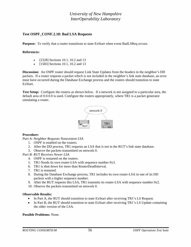
University of New Hampshire InterOperability Laboratory
Test OSPF_CONF.2.18: Bad LSA Requests Purpose: To verify that a router transitions to state ExStart when event BadLSReq occurs. References:
• [2328] Sections 10.1, 10.2 and 13 • [1583] Sections 10.1, 10.2 and 13
Discussion: An OSPF router should request Link State Updates from the headers in the neighbor’s DD packets. If a router requests a packet which is not included in the neighbor’s link state database, an error must have occurred during the Database Exchange process and the routers should transition to state ExStart. Test Setup: Configure the routers as shown below. If a network is not assigned to a particular area, the default area of 0.0.0.0 is used. Configure the routers appropriately, where TR1 is a packet generator simulating a router.
network 0
RUTTR1
Procedure: Part A: Neighbor Requests Nonexistent LSA
1. OSPF is enabled on the routers. 2. After the DD process, TR1 requests an LSA that is not in the RUT’s link state database. 3. Observe the packets transmitted on network 0.
Part B: RUT Receives Newer LSA 4. OSPF is restarted on the routers. 5. TR1 floods its own router-LSA with sequence number 0x3. 6. TR1 is shut down for more than RouterDeadInterval. 7. TR1 is restarted. 8. During the Database Exchange process, TR1 includes its own router-LSA in one of its DD
packets with a higher sequence number. 9. After the RUT requests this LSA, TR1 transmits its router-LSA with sequence number 0x2. 10. Observe the packets transmitted on network 0.
Observable Results:
• In Part A, the RUT should transition to state ExStart after receiving TR1’s LS Request. • In Part B, the RUT should transition to state ExStart after receiving TR1’s LS Update containing
the older version of the LSA. Possible Problems: None.
ROUTING CONSORTIUM 56 OSPF Operations Test Suite

University of New Hampshire InterOperability Laboratory
Test OSPF_CONF.2.19: MaxAge Flooding Purpose: To verify that a router properly floods an LSA when its age reaches MaxAge. References:
• [2328] Section 14 • [1583] Section 14
Discussion: An LSA in the link state database should only reach MaxAge if the neighbor which originated the LSA is no longer on the network. These LSAs are removed from the link state database by flooding them with the Age field set to MaxAge (3600 seconds). Test Setup: Configure the routers as shown below. If a network is not assigned to a particular area, the default area of 0.0.0.0 is used. Configure the routers appropriately, where TR1 is a packet generator simulating a router.
network 0
RUTTR1
Procedure: Part A: MaxAge
1. OSPF is enabled on the routers. 2. After the routers synchronize, TR1 should send a router-LSA with its age set to 3575 seconds. 3. Approximately 25 seconds later, observe the packets transmitted on the network.
Observable Results:
• In Part A, when TR1's router-LSA reaches MaxAge (1 hour) in the RUT's link state database, the RUT should flood the LSA with age set to 3600 seconds.
Possible Problems: None.
ROUTING CONSORTIUM 57 OSPF Operations Test Suite

University of New Hampshire InterOperability Laboratory
Test OSPF_CONF.2.20: LSA Refresh
Purpose: To verify that a router properly transmits a new instance of a self-originated LSA when its age reaches LSRefreshTime in its link state database. References:
• [2328] Section 12.4 • [1583] Section 12.4
Discussion: To keep the LSAs in the routing domain from reaching MaxAge, a router should transmit a new instance of its self-originated LSAs when they reach LSRefreshTime (1800 seconds) in its link state database. Test Setup: Configure the routers as shown below. If a network is not assigned to a particular area, the default area of 0.0.0.0 is used.
network 0
RUTTR1
Procedure: Part A: LSRefresh Time
1. OSPF is enabled on the routers. 2. Approximately 30 minutes after the RUT and TR1 are enabled, observe the packets transmitted
on network 0. Observable Results:
• In Part A, the RUT should flood all of its self-originated LSAs when they reach LSRefreshTime. This should occur approximately 30 minutes after the RUT was started.
Possible Problems: None.
ROUTING CONSORTIUM 58 OSPF Operations Test Suite

University of New Hampshire InterOperability Laboratory
Test OSPF_CONF.2.21: LSA Removed from Retransmission Purpose: To verify that a router removes an LSA from its link state retransmission list when that LSA has been removed from its link state database. References:
• [2328] Section 12.2 • [1583] Section 12.2
Discussion: A router should remove an LSA from its LS Retransmission List if that LSA is removed from its link state database. Test Setup: Configure the routers as shown below. If a network is not assigned to a particular area, the default area of 0.0.0.0 is used.
network 0
network 1
RUTTR1 TR2 TR3
Procedure: Part A: The RUT stops retransmitting an old LSA
1. TR3's interface to network 1 should be down. 2. OSPF is enabled on the routers so that the RUT is DR on network 0. 3. TR1 is unplugged from network 0. 4. TR3 is enabled on network 1. TR3 should originate a new router-LSA on network 0, including
its link to network 1. 5. After the RUT begins retransmitting TR3's new router-LSA to TR1, TR3's interface to network 1
is disabled. TR3 should originate a new router-LSA on network 0, without the link to network 1. 6. Observe the packets transmitted on network 0 and network 1.
Observable Results:
• In Part A, the RUT should stop retransmitting TR3's previous router-LSA, and only retransmit the newer instance.
Possible Problems: None.
ROUTING CONSORTIUM 59 OSPF Operations Test Suite

University of New Hampshire InterOperability Laboratory
Test OSPF_CONF.2.22: Neighbor State Down Purpose: To verify the handling of packets from routers in state down. References:
• [2328] Sections 10.6, 10.7, and 13 • [1583] Sections 10.6, 10.7, and 13
Discussion: If a neighbor’s state is Down, any Database Description Packet sent by it shall be rejected. Link State Request Packets should be accepted when the neighbor is in states Exchange, Loading, or Full. In all other states Link State Request Packets should be ignored. Link State Update packets are associated with a particular neighbor, and a particular area. If the neighbor is in a lesser state than Exchange, the packet should be dropped without further processing. Test Setup: Configure the routers as shown below. If a network is not assigned to a particular area, the default area of 0.0.0.0 is used. Configure the routers appropriately, where TR1 is a packet generator simulating a router.
network 0
RUTTR1
Procedure: Part A: TR1 in state Down sends a DD Packet
1. Enable OSPF on the RUT. 2. TR1 transmits a DD Packet on network 0. 3. Observe the packets transmitted on network 0.
Part B: TR1 in state Down sends LSRequest 4. Restart OSPF on the RUT. 5. TR1 transmits a LSRequest to the RUT on network 0. 6. Observe the packets transmitted on network 0.
Part C: TR1 in state Down transmits LSUpdate 7. Restart OSPF on the RUT. 8. TR1 transmits a Router-LSA to the RUT on network 0. 9. Observe the packets transmitted on network 0.
Observable Results:
• In Part A, the RUT should ignore the DD Packet transmitted by TR1. • In Part B, the RUT should ignore the LSRequest Packet transmitted by TR1. • In Part C, the RUT should ignore the Router-LSA transmitted by TR1.
ROUTING CONSORTIUM 60 OSPF Operations Test Suite

University of New Hampshire InterOperability Laboratory
Possible Problems: None.
ROUTING CONSORTIUM 61 OSPF Operations Test Suite

University of New Hampshire InterOperability Laboratory
GROUP 3: Link State Advertisements Overview The following tests verify the origination and receipt of Link State Advertisements. Discussion Link State Advertisements are used to create and maintain a link state database. The five types of LSAs describe different entities in the OSPF domain. References: RFC 1583 – Sections 2, 12 and 14 RFC 2328 – Sections 2, 12 and 14
ROUTING CONSORTIUM 62 OSPF Operations Test Suite

University of New Hampshire InterOperability Laboratory
Test OSPF_CONF.3.1: Transit Link Router LSAs Purpose: To verify that a router transmits a new router-LSA when an attached network changes from a stub network to a transit network. References:
• [2328] Section 12.4.1.2 • [1583] Section 12.4.1
Discussion: When a router is BDR or DR Other on a network, it should transmit a new router-LSA when it becomes adjacent with the DR. Test Setup: Configure the routers as shown below. If a network is not assigned to a particular area, the default area of 0.0.0.0 is used.
network 0
RUTTR1
Procedure: Part A: RUT is DR Other
1. Configure the RUT to have priority 0. TR1 should have priority 1. 2. Enable OSPF on the RUT and wait for RouterDeadInterval. 3. TR1 is enabled. 4. Observe the packets transmitted on network 0.
Part B: RUT is BDR 5. Disable the RUT 6. Configure the RUT to have priority 1. 7. TR1 is enabled and should become DR. Enable OSPF on the RUT. 8. Observe the packets transmitted on network 0.
Observable Results:
• In Parts A and B, after the routers synchronize, the RUT should transmit a router-LSA with its interface to network 0 described by a type 2 (transit) link. The Link ID of this link should be set to the IP Address of TR1.
Possible Problems: None.
ROUTING CONSORTIUM 63 OSPF Operations Test Suite

University of New Hampshire InterOperability Laboratory
Test OSPF_CONF.3.2: Router LSAs with DR Changes Purpose: To verify that a router transmits a new router-LSA when an attached network changes from a stub network to a transit network. References:
• [2328] Section 12.4.1.2 • [1583] Section 12.4.1
Discussion: When a network's DR changes, as long as there are at least two adjacent routers on the network, they should all originate new router-LSAs with a type 2 Link describing that network. The Link ID of this type 2 Link should be set to the IP Address of the new DR. Test Setup: Configure the routers as shown below. If a network is not assigned to a particular area, the default area of 0.0.0.0 is used. Configure the routers to all have priority 1.
network 0
RUTTR1 TR2
Procedure: Part A: RUT as DR Other
1. OSPF is enabled on the routers so that TR1, TR2 and the RUT become DR, BDR and DR Other, respectively.
2. TR1 is disabled. 3. Observe the packets transmitted on network 0.
Part B: RUT as DR Other 4. TR1 is enabled and should become DR Other. 5. TR2 is disabled. 6. Observe the packets transmitted on network 0.
Part C: RUT with priority 0 7. Configure the RUT to have priority 0. 8. OSPF is restarted on all the routers so that TR1, TR2 and the RUT become DR, BDR and DR
Other, respectively. 9. TR1 is disabled. 10. Observe the packets transmitted on network 0.
Observable Results:
• In Part A, after TR1 is disabled for the first time, the RUT should transmit a new router-LSA with the Link ID of the type 2 Link for network 0 set to TR2’s IP Address.
• In Part B, after TR2 is disabled, the RUT should transmit a new router-LSA with the Link ID for network 0 set to its interface to network 0.
ROUTING CONSORTIUM 64 OSPF Operations Test Suite

University of New Hampshire InterOperability Laboratory
• In Part C, after TR1 is disabled, the RUT should transmit a new router-LSA with the Link ID for network 0 set to TR2’s IP Address.
Possible Problems: None.
ROUTING CONSORTIUM 65 OSPF Operations Test Suite
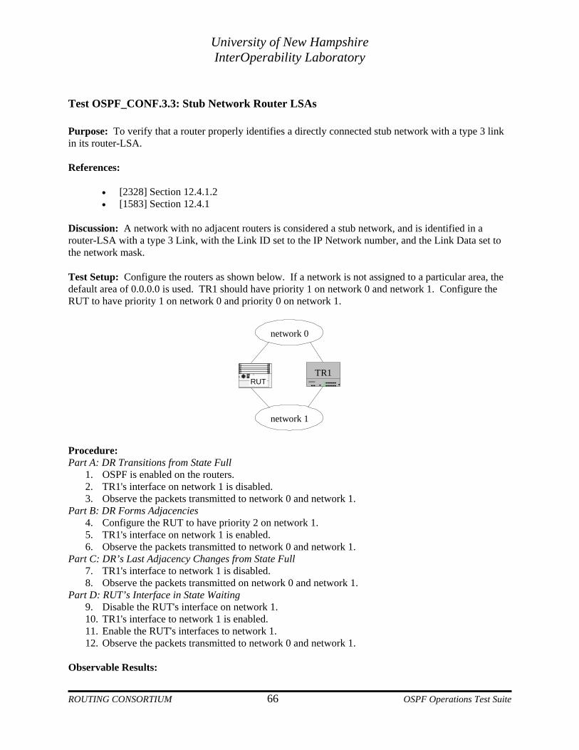
University of New Hampshire InterOperability Laboratory
Test OSPF_CONF.3.3: Stub Network Router LSAs Purpose: To verify that a router properly identifies a directly connected stub network with a type 3 link in its router-LSA. References:
• [2328] Section 12.4.1.2 • [1583] Section 12.4.1
Discussion: A network with no adjacent routers is considered a stub network, and is identified in a router-LSA with a type 3 Link, with the Link ID set to the IP Network number, and the Link Data set to the network mask. Test Setup: Configure the routers as shown below. If a network is not assigned to a particular area, the default area of 0.0.0.0 is used. TR1 should have priority 1 on network 0 and network 1. Configure the RUT to have priority 1 on network 0 and priority 0 on network 1.
network 0
network 1
RUTTR1
Procedure: Part A: DR Transitions from State Full
1. OSPF is enabled on the routers. 2. TR1's interface on network 1 is disabled. 3. Observe the packets transmitted to network 0 and network 1.
Part B: DR Forms Adjacencies 4. Configure the RUT to have priority 2 on network 1. 5. TR1's interface on network 1 is enabled. 6. Observe the packets transmitted to network 0 and network 1.
Part C: DR’s Last Adjacency Changes from State Full 7. TR1's interface to network 1 is disabled. 8. Observe the packets transmitted on network 0 and network 1.
Part D: RUT’s Interface in State Waiting 9. Disable the RUT's interface on network 1. 10. TR1's interface to network 1 is enabled. 11. Enable the RUT's interfaces to network 1. 12. Observe the packets transmitted to network 0 and network 1.
Observable Results:
ROUTING CONSORTIUM 66 OSPF Operations Test Suite

University of New Hampshire InterOperability Laboratory
• In Part A, the RUT should transmit a new router-LSA to network 0 with a type 3 (stub) link containing network 1's IP Address as the Link ID.
• In Part B, after the RUT and TR1 become adjacent on network 1, the RUT should transmit a new router-LSA with a type 2 (transit) link containing its own IP Address as both the Link ID and Link Data.
• In Part C, the RUT should transmit a new router-LSA to network 0 with a type 3 (stub) link containing network 1's IP Address as the Link ID.
• In Part D, when the RUT's interface comes up on network 1 it should go through state Waiting before it becomes adjacent with TR1. During this time, the RUT should transmit a new router-LSA to network 0 with a type 3 (stub) link containing network 1's IP Address in the LinkID field.
Possible Problems: None.
ROUTING CONSORTIUM 67 OSPF Operations Test Suite
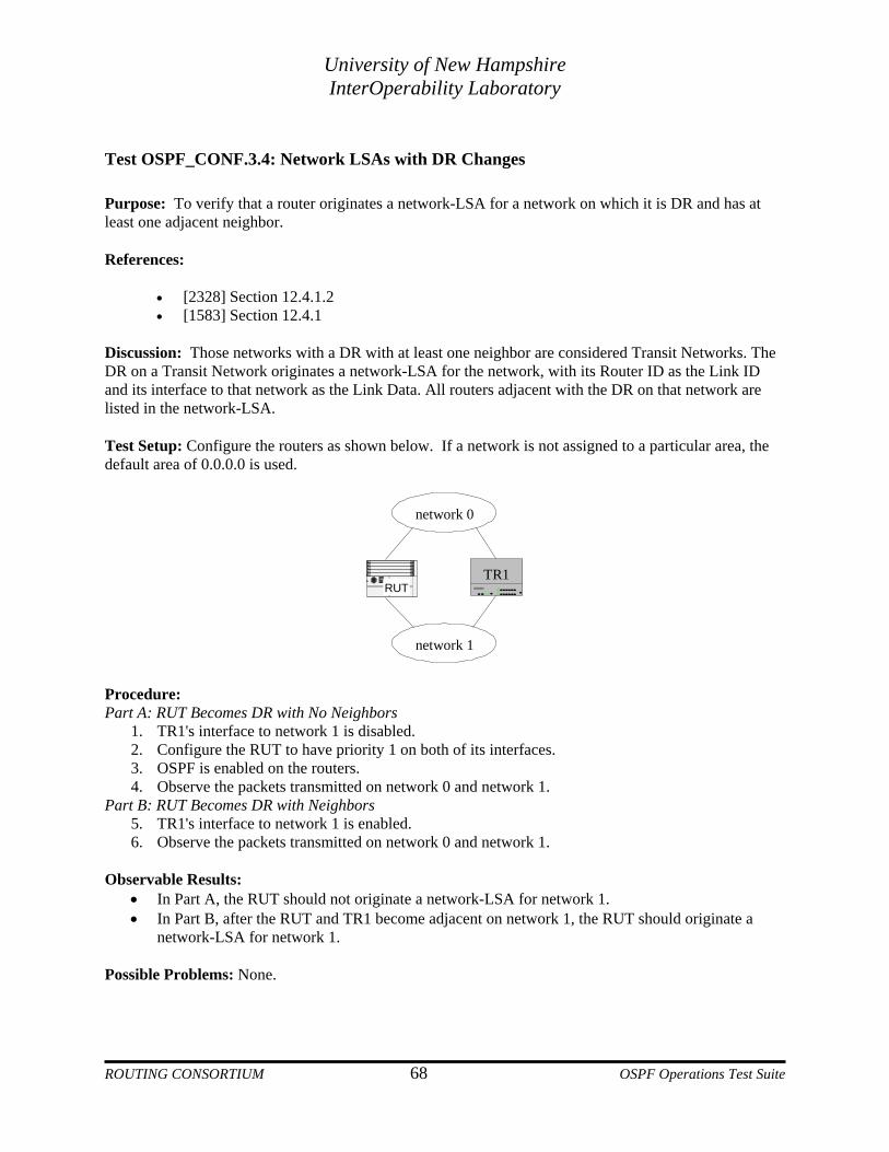
University of New Hampshire InterOperability Laboratory
Test OSPF_CONF.3.4: Network LSAs with DR Changes Purpose: To verify that a router originates a network-LSA for a network on which it is DR and has at least one adjacent neighbor. References:
• [2328] Section 12.4.1.2 • [1583] Section 12.4.1
Discussion: Those networks with a DR with at least one neighbor are considered Transit Networks. The DR on a Transit Network originates a network-LSA for the network, with its Router ID as the Link ID and its interface to that network as the Link Data. All routers adjacent with the DR on that network are listed in the network-LSA. Test Setup: Configure the routers as shown below. If a network is not assigned to a particular area, the default area of 0.0.0.0 is used.
network 0
network 1
RUTTR1
Procedure: Part A: RUT Becomes DR with No Neighbors
1. TR1's interface to network 1 is disabled. 2. Configure the RUT to have priority 1 on both of its interfaces. 3. OSPF is enabled on the routers. 4. Observe the packets transmitted on network 0 and network 1.
Part B: RUT Becomes DR with Neighbors 5. TR1's interface to network 1 is enabled. 6. Observe the packets transmitted on network 0 and network 1.
Observable Results:
• In Part A, the RUT should not originate a network-LSA for network 1. • In Part B, after the RUT and TR1 become adjacent on network 1, the RUT should originate a
network-LSA for network 1. Possible Problems: None.
ROUTING CONSORTIUM 68 OSPF Operations Test Suite

University of New Hampshire InterOperability Laboratory
Test OSPF_CONF.3.5: Attached Routers in Network LSAs Purpose: To verify that when a router originates a network-LSA, it lists all of those routers with which it is fully adjacent in the LSA. References:
• [2328] Section 12.4.2 • [1583] Section 12.4.2
Discussion: The DR of every transit Broadcast or NBMA network generates a network-LSA. All of the routers that are adjacent with the DR on that network are listed in the "Attached Routers" section of the network-LSA. Test Setup: Configure the routers as shown below. If a network is not assigned to a particular area, the default area of 0.0.0.0 is used.
network 0
network 1
RUTTR1 TR2
Procedure: Part A: DR and Neighbor Enter State Full
1. TR2's interface to network 1 is disabled. 2. Configure the RUT to have priority 1 on both of its interfaces. 3. OSPF is enabled on the routers so that the RUT and TR1 become DR and BDR on network 1,
respectively. 4. After the routers have synchronized, TR2's interface to network 1 is enabled. 5. Observe the packets transmitted on network 0 and network 1.
Part B: DR and Neighbor Leave Full 6. TR2's interface to network 1 is unplugged. 7. Observe the packets transmitted on network 0 and network 1.
Observable Results:
• In Part A, after becoming adjacent with TR2 on network 1, the RUT should originate a new network-LSA for network 1 listing itself, TR1 and TR2 as attached routers.
• In Part B, approximately RouterDeadInterval after TR2's last Hello packet, the RUT should transmit a new network-LSA for network 1 that does not include TR2 as an attached router.
Possible Problems: None.
ROUTING CONSORTIUM 69 OSPF Operations Test Suite

University of New Hampshire InterOperability Laboratory
Test OSPF_CONF.3.6: Intra-Area Summary ASBR-LSAs Purpose: To verify that an ABR properly originates a summary-ASBR-LSA when it has an intra-area route to an ASBR. References:
• [2328] Sections 12.4 and 12.4.3 • [1583] Sections 12.4 and 12.4.3
Discussion: An ABR should originate a summary-ASBR-LSA for a router that sets the E bit in its router-LSA. The ABR should only generate this summary-ASBR-LSA into areas in which the ASBR being advertised does not have an interface. The LinkID field should be set to the Router ID of the ASBR being advertised, and the AdvertisingRouter field should be set to the Router ID of the ABR advertising a route to the ASBR. The Metric field should be set to the cost of the ABR's best route to the ASBR. The summary-ASBR-LSA must not be sent into stub areas. Test Setup: Configure the routers as shown below. If a network is not assigned to a particular area, the default area of 0.0.0.0 is used. TR1 is an ASBR. Configure the cost of the RUT’s interface to network 0 to 1 and network 1 to 2. All other costs should be 1.
Area 2 (stub)Area 1
network 0
network 2
network 1
network 3
BackboneTR1ASBR
TR2RUT
1
1
1 1
1 1
11 1
2
Procedure: Part A: Lower Cost Path to ASBR Available
1. OSPF is enabled on all the routers. 2. After the routers have synchronized, enable the RUT's interface to network 0. 3. Observe the packets transmitted on all networks.
Part B: Current Path to ASBR Disabled 4. Disable the RUT's interface to network 0. 5. Observe the packets transmitted on all networks.
ROUTING CONSORTIUM 70 OSPF Operations Test Suite

University of New Hampshire InterOperability Laboratory
Part C: Topology Change Creates More Expensive Lowest Cost Path 6. TR1's interface to network 1 is disabled. 7. Observe the packets transmitted on all networks.
Part D: ASBR No Longer Reachable 8. TR2's interface to network 0 is disabled. 9. Observe the packets transmitted on all networks.
Part E: Router is No Longer ASBR 10. Enable RUT's interface to network 0. The RUT should originate a new summary-ASBR-LSA for
TR1 with metric 1. 11. TR1 is not an ASBR. 12. Observe the packets transmitted on all networks.
Observable Results:
• In Part A, the RUT should originate a new summary-ASBR-LSA for TR1 with metric 1. This LSA should only be sent to network 2.
• In Part B, the RUT should originate a new summary-ASBR-LSA for TR1 with metric 2. This LSA should only be sent to network 2.
• In Part C, the RUT should originate a new summary-ASBR-LSA for TR1 with metric 3. This LSA should only be sent to network 2.
• In Parts D and E, the RUT should MaxAge its summary-ASBR-LSA for TR1. This LSA should only be sent to network 2.
Possible Problems: TR1 should be a router that allows the user to change the ASBR status without resetting.
ROUTING CONSORTIUM 71 OSPF Operations Test Suite

University of New Hampshire InterOperability Laboratory
Test OSPF_CONF.3.7: Intra-Area Summary Network LSAs Purpose: To verify that an ABR properly originates a summary-network-LSA for a network for which it has an intra-area route. References:
• [2328] Sections 12.4 and 12.4.3 • [1583] Sections 12.4 and 12.4.3
Discussion: Summary-network-LSAs are originated by ABR advertising networks in other areas. Only networks to which the ABR has an intra-area route are advertised into the backbone, while networks to which it has either an intra-area or inter-area route are advertised into non-backbone areas. A summary-LSA should not be originated into the area in which the destination resides. It is optional to advertise summary-network-LSAs into stub areas; default routing can be used instead. Test Setup: Configure the routers as shown below. If a network is not assigned to a particular area, the default area of 0.0.0.0 is used.
Area 2 (stub)Area 1
network 0
network 2
network 1
network 3
Backbone
TR1RUT
2
1
1 1
11 1
2
Procedure: Part A: RUT Advertises All Networks in an Area
1. Configure the cost of the RUT’s interface to network 0 to be 1 and network 1 to be 2. 2. TR1’s cost to network 0 is 2. All other costs are 1. 3. Disable RUT's interface to network 0. 4. OSPF is restarted on all the routers. 5. After the routers have synchronized, enable the RUT's interface to network 0. 6. Observe the packets transmitted on all networks.
Part B: Cost of Intra-Area Path Increases 7. Disable the RUT's interface to network 0. 8. Observe the packets transmitted on all networks.
ROUTING CONSORTIUM 72 OSPF Operations Test Suite

University of New Hampshire InterOperability Laboratory
Part C: Cost of Intra-Area Path Decreases 9. TR1’s cost to network 0 is 1. 10. Observe the packets transmitted on all networks.
Part D: Intra-Area Path No Longer Exists 11. TR1’s interface to network 0 is disabled. 12. Observe the packets transmitted on all networks.
Observable Results: • In Part A, the RUT should originate a new summary-network-LSA for network 0 with metric 1.
This LSA should only be sent to network 2 and network 3. • In Part B, the RUT should originate a new summary-network-LSA for network 0 with metric 4.
This LSA should only be sent to network 2 and network 3. • In Part C, the RUT should originate a new summary-network-LSA for network 0 with metric 3.
This LSA should only be sent to network 2 and network 3. • In Part D, the RUT should MaxAge its summary-network-LSA for network 0. This LSA should
only be sent to network 2 and network 3. Possible Problems: None.
ROUTING CONSORTIUM 73 OSPF Operations Test Suite

University of New Hampshire InterOperability Laboratory
Test OSPF_CONF.3.8: Inter-Area Summary ASBR LSAs Purpose: To verify that an ABR properly originates a summary-ASBR-LSA when it has an inter-area route to an ASBR. References:
• [2328] Sections 12.4 and 12.4.3 • [1583] Sections 12.4 and 12.4.3
Discussion: An ABR should originate a summary-ASBR-LSA for a router that sets the E bit in its router-LSA. The ABR should only generate this summary-ASBR-LSA into areas in which the ASBR being advertised does not have an interface. The LinkID field should be set to the Router ID of the ASBR being advertised, and the AdvertisingRouter field should be set to the Router ID of the ABR advertising a route to the ASBR. The Metric field should be set to the cost of the ABR's best route to the ASBR. The summary-ASBR-LSA must not be sent into stub areas. Test Setup: Configure the routers as shown below. If a network is not assigned to a particular area, the default area of 0.0.0.0 is used. The costs of TR2’s interface to network 2 and TR3’s interface to network 3 each should be 3. The cost of the RUT’s interface to network 2 should be 3. All other costs should be set to 1. TR4 is an ASBR.
Area 2Area 1
network 1
network 0
network 2
network 3
Backbone
1
1 3
1
TR3
TR2
RUT
TR1TR4ASBR
3
1 3
1
Procedure: Part A: ASBR Becomes Available
1. OSPF is enabled on the routers. 2. Observe the packets transmitted on all networks.
Part B: Lower Cost Path Becomes Available 3. The cost of TR2’s interface to network 2 is 1. 4. Observe the packets transmitted on all networks.
Part C: Lowest Cost Path to an ASBR Increases 5. TR2's interface to network 2 is disabled.
ROUTING CONSORTIUM 74 OSPF Operations Test Suite
University of New Hampshire InterOperability Laboratory
6. Observe the packets transmitted on all networks. Part D: Lowest Cost Path to an ASBR Decreases
7. The cost of TR3’s interface to network 3 is 1. 8. Observe the packets transmitted on all networks.
Part E: ABR Advertises a Higher Cost Path 9. The cost of TR3’s interface to network 3 is 6. 10. Observe the packets transmitted on all networks.
Part F: ABR Advertising Path to ASBR Becomes Unavailable 11. TR3’s interface to network 2 is disabled. 12. Observe the packets transmitted on all networks.
Part G: ASBR Becomes Unreachable 13. TR3’s interface to network 2 is enabled. 14. After the RUT originates a summary-ASBR-LSA for TR4 to network 0, TR4 is disabled. 15. Observe the packets transmitted on all networks.
Observable Results:
• In Part A, the RUT should transmit a summary-ASBR-LSA to network 0 for TR4 with the AdvertisingRouter field set to its Router ID. The metric should be set to 6.
• In Part B, the RUT should transmit a new summary-ASBR-LSA with metric 5. • In Part C, the RUT should transmit a new summary-ASBR-LSA with metric 6. • In Part D, the RUT should transmit a new summary-ASBR-LSA with metric 4. • In Part E, the RUT should transmit a new summary-ASBR-LSA with metric 9. • In Parts F and G, the RUT should transmit a new instance of the summary-ASBR-LSA with
MaxAge. Possible Problems: None.
ROUTING CONSORTIUM 75 OSPF Operations Test Suite

University of New Hampshire InterOperability Laboratory
Test OSPF_CONF.3.9: Inter-Area Summary LSAs Purpose: To verify that an ABR properly transmits summary-network-LSAs for those networks reachable by inter-area routes. References:
• [2328] Sections 12.4 and 12.4.3 • [1583] Sections 12.4 and 12.4.3
Discussion: An ABR originates summary-network-LSAs to advertise routes for which it has an intra-area or inter-area path. Routes for which the ABR has only inter-area paths should only be advertised to non-backbone areas (since the ABR's path for that route must go through the backbone). The cost of the summary-network-LSA should be the combined cost of the ABR's best intra-area route to the ABR it uses to reach the destination and the cost advertised by that ABR. Test Setup: Configure the routers as shown below. If a network is not assigned to a particular area, the default area of 0.0.0.0 is used. The cost of TR3's interface to network 3 is 4. The cost of the RUT’s interface to network 2 should be set to 3 and the cost of TR2’s interface to network 2 is 6. All other costs should be set to 1. The RUT and TR1 must not have direct links to network 3. The RUT should not have an IP Address defined on network 3.
Area 2
Backbone
Area 1
network 1 network 2
network 0 network 3
1
1
1 6
1
4
1
3
RUT
TR1
TR2
TR32
Procedure: Part A: RUT Advertises for Every Reachable Destination
1. OSPF is enabled on the routers. TR2’s interface to network 3 is disabled. 2. Observe the packets transmitted on all networks.
Part B: Path to Network Increases 3. The cost of TR3's interface to network 3 is 5. 4. Observe the packets transmitted on all networks.
Part C: Path to Network Decreases 5. The cost of TR3's interface to network 3 is 4. 6. Observe the packets transmitted on all networks.
ROUTING CONSORTIUM 76 OSPF Operations Test Suite

University of New Hampshire InterOperability Laboratory
Part D: Cost to ABR Increases 7. Configure the cost of the RUT’s interface to network 2 to 8. 8. Observe the packets transmitted on all networks.
Part E: Cost to ABR Decreases 9. The cost of TR2's interface to network 2 is 5. 10. Observe the packets transmitted on all networks.
Part F: Lower Cost Path Available 11. TR2 is enabled on network 3 in Area 2 with a cost of 2. 12. Observe the packets transmitted on all networks.
Part G: Best Cost Path Goes Down 13. TR2 is disabled. 14. Observe the packets transmitted on all networks.
Part H: Network No Longer Reachable 15. TR3’s interface to network 3 is disabled. 16. Observe the packets transmitted on all networks.
Part I: ABR No Longer Reachable 17. TR3’s interface to network 3 is enabled. 18. Observe the packets transmitted for a summary-network-LSA sent to network 0 for network 3. 19. TR3’s interface to network 2 is unplugged. 20. Observe the packets transmitted on all networks.
Observable Results:
• In Part A, the RUT should transmit a summary-network-LSA to network 0 advertising network 3 with a metric of 7.
• In Part B, the RUT should transmit a summary-network-LSA to network 0 advertising network 3 with a metric of 8.
• In Part C, the RUT should transmit a summary-network-LSA to network 0 advertising network 3 with a metric of 7.
• In Part D, the RUT should transmit a summary-network-LSA to network 0 advertising network 3 with metric of 11.
• In Part E, the RUT should transmit a summary-network-LSA to network 0 advertising network 3 with metric of 10.
• In Part F, the RUT should transmit a summary-network-LSA to network 0 advertising network 3 with metric of 3.
• In Part G, the RUT should transmit a new summary-network-LSA to network 0 advertising network 3 with metric of 12.
• In Part H, the RUT should flush its summary-network-LSA for network 3. • In Part I, the RUT should flush its summary-network-LSA for network 3 after
RouterDeadInterval seconds. Possible Problems: None.
ROUTING CONSORTIUM 77 OSPF Operations Test Suite
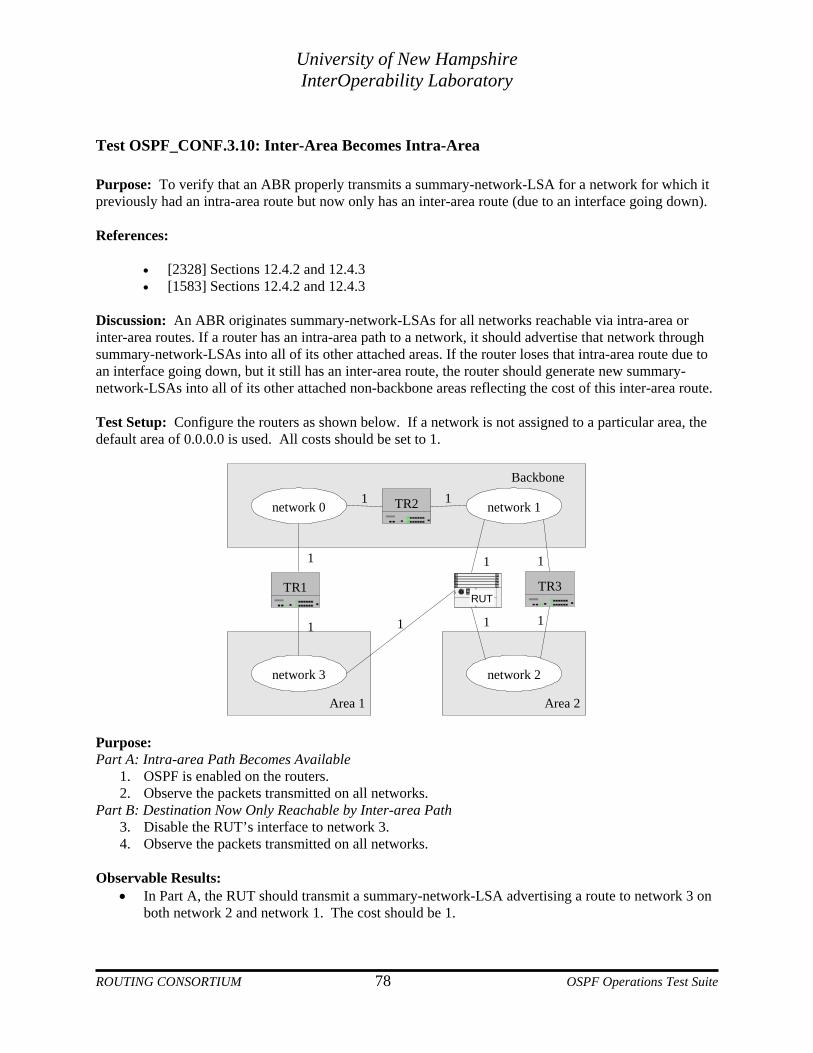
University of New Hampshire InterOperability Laboratory
Test OSPF_CONF.3.10: Inter-Area Becomes Intra-Area Purpose: To verify that an ABR properly transmits a summary-network-LSA for a network for which it previously had an intra-area route but now only has an inter-area route (due to an interface going down). References:
• [2328] Sections 12.4.2 and 12.4.3 • [1583] Sections 12.4.2 and 12.4.3
Discussion: An ABR originates summary-network-LSAs for all networks reachable via intra-area or inter-area routes. If a router has an intra-area path to a network, it should advertise that network through summary-network-LSAs into all of its other attached areas. If the router loses that intra-area route due to an interface going down, but it still has an inter-area route, the router should generate new summary-network-LSAs into all of its other attached non-backbone areas reflecting the cost of this inter-area route. Test Setup: Configure the routers as shown below. If a network is not assigned to a particular area, the default area of 0.0.0.0 is used. All costs should be set to 1.
Area 2Area 1
network 0
network 3
network 1
network 2
Backbone
1
1 1
1
TR3
TR21 1
TR1RUT
1
1 1
Purpose: Part A: Intra-area Path Becomes Available
1. OSPF is enabled on the routers. 2. Observe the packets transmitted on all networks.
Part B: Destination Now Only Reachable by Inter-area Path 3. Disable the RUT’s interface to network 3. 4. Observe the packets transmitted on all networks.
Observable Results:
• In Part A, the RUT should transmit a summary-network-LSA advertising a route to network 3 on both network 2 and network 1. The cost should be 1.
ROUTING CONSORTIUM 78 OSPF Operations Test Suite
University of New Hampshire InterOperability Laboratory
• In Part B, the RUT should transmit a new summary-network-LSA for network 3 to network 2 with metric 3. It should also MaxAge its summary-network-LSA for network 3 on network 1.
Possible Problems: None.
ROUTING CONSORTIUM 79 OSPF Operations Test Suite

University of New Hampshire InterOperability Laboratory
Test OSPF_CONF.3.11: Area Ranges with RFC 2328 Purpose: To verify that an ABR properly uses a configured address range, as per RFC 2328. References
• [2328] Sections 12.4 and 12.4.3
Discussion: An ABR can be configured with an address range so that it can advertise multiple networks in a single summary-network-LSA. As soon as any of the component networks of that address range become reachable by intra-area routes, the ABR should transmit a summary-network-LSA advertising the address range. According to RFC 2178 and later specifications, the ABR should compare the best path costs of each of the reachable component networks, and use the highest of these when advertising the address range. Test Setup: Configure the routers as shown below. If a network is not assigned to a particular area, the default area of 0.0.0.0 is used. Configure the cost of the RUT’s interfaces to network 0 should be 1, network 1 should be 7, network 2 should be 3 and network 3 should be 1. All other costs should be 1.
Area 2
Backbone
Area 1
network 0
network 1
network 2
network 3
1
17 1
31
1
TR2 RUT TR1
Procedure: Part A: No intra-area Path to Range
1. Configure an address range on the RUT for network 0 and network 1 in Area 1. 2. Disable the RUT's interfaces to network 0 and network 1. 3. TR1’s interface on network 0 is enabled. 4. OSPF is enabled on the routers. 5. Observe the packets transmitted on all networks.
Part B: Range Reachable via Intra-area Path 6. Enable the RUT's interface to network 1. 7. TR1’s interface to network 0 is disabled. 8. Observe the packets transmitted on all networks.
Part C: Highest Cost Component Decreases 9. Enable the RUT's interface to network 0. 10. Observe the packets transmitted on all networks.
Part D: Highest Cost Component Increases 11. The cost of TR2's interface to network 1 is 3.
ROUTING CONSORTIUM 80 OSPF Operations Test Suite
University of New Hampshire InterOperability Laboratory
12. Observe the packets transmitted on all networks. Observable Results:
• In Part A, the RUT should transmit summary-network-LSAs for network 0 and network 1 to network 3, but not network 2. The RUT should not use its configured address range yet.
• In Part B, the RUT should transmit a new summary-network-LSA for the address range to network 2 and network 3 with cost 8.
• In Part C, the RUT should transmit a new summary-network-LSA for the address range to network 2 and network 3 with cost 2.
• In Part D, the RUT should transmit a new summary-network-LSA for the address range to network 2 and network 3 with cost 4.
Possible Problems: None.
ROUTING CONSORTIUM 81 OSPF Operations Test Suite

University of New Hampshire InterOperability Laboratory
Test OSPF_CONF.3.12: Flushing Summary Area Range LSAs Purpose: To verify that an ABR properly flushes any advertisements it originated for a configured address range when all of the component networks become unreachable. References:
• [2328] Sections 12.4 and 12.4.3 • [1583] Sections 12.4 and 12.4.3
Discussion: An ABR can be configured with an address range so that it can advertise multiple networks in a single summary-network-LSA. As soon as any of the component networks of that address range become reachable by intra-area routes, the ABR should transmit a summary-network-LSA advertising the address range. When none of the component networks of the range are reachable, the ABR should no longer advertise the address range. If some of the component networks of the range are reachable and the status of the range is set to DoNotAdvertise, the router should not originate any summary-network-LSAs for the address range. Test Setup: Configure the routers as shown below. If a network is not assigned to a particular area, the default area of 0.0.0.0 is used. The address range configured is 10.10.10.0/23.
Area 2Area 1
network 0
network 1
TR2
network 2
network 3
TR1RUT
Backbone
1
1
1
3
2 1
1
Procedure: Part A: Range Status Set to DoNotAdvertise
1. Configure an address range on the RUT and TR1 for network 0 and network 1 in Area 1, set to DoNotAdvertise.
2. OSPF is enabled on the routers. 3. Observe the packets transmitted on all networks.
Part B: Range Not Reachable 4. Change the status of the address range on the RUT to Advertise. The RUT should transmit a
summary-network-LSA with the address range to network 2 and network 3. 5. Disable the RUT's interfaces to network 0 and network 1. 6. Observe the packets transmitted on all networks.
ROUTING CONSORTIUM 82 OSPF Operations Test Suite

University of New Hampshire InterOperability Laboratory
Observable Results:
• In Part A, the RUT should not transmit a summary-network-LSA for the address range. • In Part B, the RUT should MaxAge its last summary-network-LSA for the address range.
Possible Problems: The RUT may support RFC 1583.
ROUTING CONSORTIUM 83 OSPF Operations Test Suite
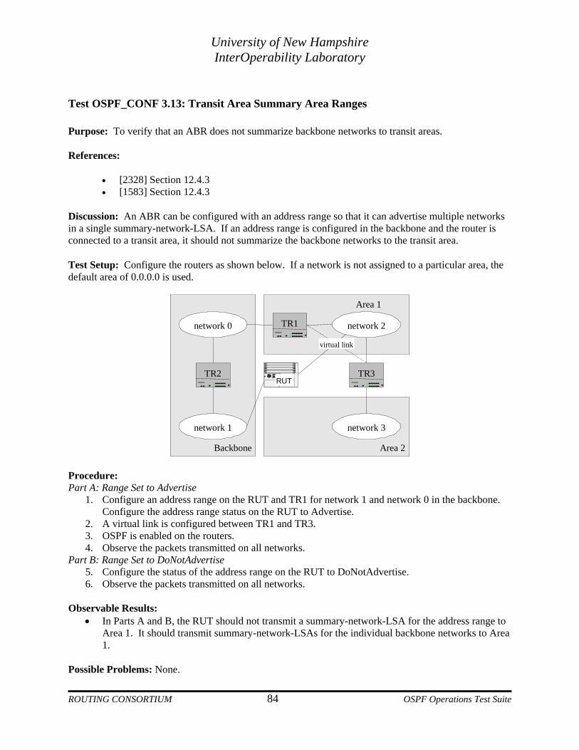
University of New Hampshire InterOperability Laboratory
Test OSPF_CONF 3.13: Transit Area Summary Area Ranges Purpose: To verify that an ABR does not summarize backbone networks to transit areas. References:
• [2328] Section 12.4.3 • [1583] Section 12.4.3
Discussion: An ABR can be configured with an address range so that it can advertise multiple networks in a single summary-network-LSA. If an address range is configured in the backbone and the router is connected to a transit area, it should not summarize the backbone networks to the transit area. Test Setup: Configure the routers as shown below. If a network is not assigned to a particular area, the default area of 0.0.0.0 is used.
Area 2Backbone
network 0
network 1
TR2
network 2
network 3
TR3RUT
Area 1
TR1
virtual link
Procedure: Part A: Range Set to Advertise
1. Configure an address range on the RUT and TR1 for network 1 and network 0 in the backbone. Configure the address range status on the RUT to Advertise.
2. A virtual link is configured between TR1 and TR3. 3. OSPF is enabled on the routers. 4. Observe the packets transmitted on all networks.
Part B: Range Set to DoNotAdvertise 5. Configure the status of the address range on the RUT to DoNotAdvertise. 6. Observe the packets transmitted on all networks.
Observable Results:
• In Parts A and B, the RUT should not transmit a summary-network-LSA for the address range to Area 1. It should transmit summary-network-LSAs for the individual backbone networks to Area 1.
Possible Problems: None. ROUTING CONSORTIUM 84 OSPF Operations Test Suite
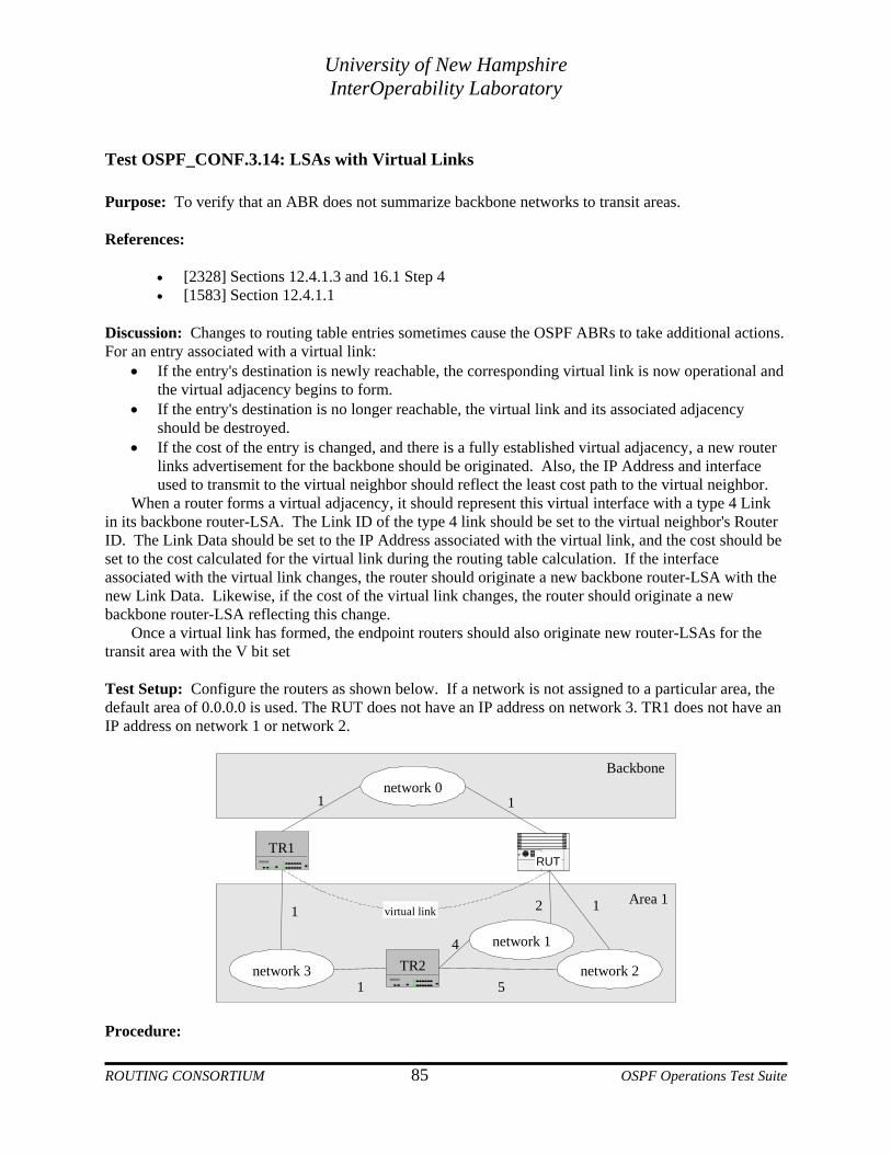
University of New Hampshire InterOperability Laboratory
Test OSPF_CONF.3.14: LSAs with Virtual Links Purpose: To verify that an ABR does not summarize backbone networks to transit areas. References:
• [2328] Sections 12.4.1.3 and 16.1 Step 4 • [1583] Section 12.4.1.1
Discussion: Changes to routing table entries sometimes cause the OSPF ABRs to take additional actions. For an entry associated with a virtual link:
• If the entry's destination is newly reachable, the corresponding virtual link is now operational and the virtual adjacency begins to form.
• If the entry's destination is no longer reachable, the virtual link and its associated adjacency should be destroyed.
• If the cost of the entry is changed, and there is a fully established virtual adjacency, a new router links advertisement for the backbone should be originated. Also, the IP Address and interface used to transmit to the virtual neighbor should reflect the least cost path to the virtual neighbor.
When a router forms a virtual adjacency, it should represent this virtual interface with a type 4 Link in its backbone router-LSA. The Link ID of the type 4 link should be set to the virtual neighbor's Router ID. The Link Data should be set to the IP Address associated with the virtual link, and the cost should be set to the cost calculated for the virtual link during the routing table calculation. If the interface associated with the virtual link changes, the router should originate a new backbone router-LSA with the new Link Data. Likewise, if the cost of the virtual link changes, the router should originate a new backbone router-LSA reflecting this change.
Once a virtual link has formed, the endpoint routers should also originate new router-LSAs for the transit area with the V bit set
Test Setup: Configure the routers as shown below. If a network is not assigned to a particular area, the default area of 0.0.0.0 is used. The RUT does not have an IP address on network 3. TR1 does not have an IP address on network 1 or network 2.
network 0
TR1RUT
network 3
network 1
network 2TR2
virtual link
Backbone
Area 1
1
1 2 1
4
51
1
Procedure: ROUTING CONSORTIUM 85 OSPF Operations Test Suite

University of New Hampshire InterOperability Laboratory
Part A: Virtual Link Enabled 1. Disable the RUT's interface to network 2. 2. Configure a virtual link between the RUT and TR1 in Area 1. 3. OSPF is enabled on the routers. 4. Observe the packets transmitted on all networks.
Part B: RUT Sets V-Bit 5. Observe the RUT’s transit area router-LSA.
Part C: Higher Cost Virtual Link Path 6. The cost of TR2’s interface to network 3 is 2. 7. Observe the packets transmitted on all networks.
Part D: Lower Cost Virtual Link Path 8. The cost of TR2’s interface to network 3 is 1. 9. Observe the packets transmitted on all networks.
Part E: Topology Change causes New Next Hop 10. Enable the RUT’s interface to network 2. 11. Observe the packets transmitted on all networks.
Part F: Router Chooses Different IP Address 12. TR1's interface to network 3 is disabled. TR1’s interfaces to network 1 and network 2 are
enabled. 13. Disable the RUT’s interfaces to networks 1 and 2 and enable the RUT on network 3 with cost 1. 14. OSPF is restarted on the routers. 15. Observe the packets transmitted on all networks.
Part G: Router Chooses Different IP Address 16. The cost of TR2’s interface to network 2 is 3. 17. Observe the packets transmitted on all networks.
Part H: End of Virtual Link No Longer Reachable 18. TR1's interfaces to networks 1 and 2 are disabled. 19. Observe the packets transmitted on all networks.
Part I: Virtual Link Disabled 20. Observe the RUT’s transit area router-LSA.
Observable Results:
• In Part A, after the virtual adjacency forms, the RUT should originate a new backbone router-LSA listing the virtual neighbor TR1 as a type 4 virtual link. The Link ID of the type 4 virtual Link should be set to TR1's Router ID, and the Link Data should be set to the IP Address of the RUT's interface to network 1. The metric of this virtual link should be set to 3.
• In Part B, after the virtual link between the RUT and TR1 becomes fully adjacent, the RUT should update its transit area router-LSA by adding the V-bit to the router options field.
• In Part C, the RUT should originate a new backbone router-LSA with the metric of the virtual link set to 4.
• In Part D, the RUT should originate a new backbone router-LSA with the metric of the virtual link set to 3.
• In Part E, the RUT should originate a new backbone router-LSA with the metric of the virtual link set to 2. The Link Data field should be set to the IP Address of the RUT’s interface to network 2.
• In Part F, the RUT should first transmit its unicast Hello packets to the IP Address of TR1’s interface to network 1.
ROUTING CONSORTIUM 86 OSPF Operations Test Suite

University of New Hampshire InterOperability Laboratory
• In Part G, after changing TR2’s cost to network 2, the RUT should transmit its unicast Hello packets to the IP Address of TR1’s interface to network 2.
• In Part H, the RUT should originate a new router-LSA for the backbone not listing the virtual neighbor.
• In Part I, the RUT should update its transit area router-LSA by removing the V-bit from the options field.
Possible Problems: The RUT may transmit unicast packets from interfaces that are not enabled in OSPF. In this case, delete the IP Addresses on these interfaces and run the tests again.
ROUTING CONSORTIUM 87 OSPF Operations Test Suite

University of New Hampshire InterOperability Laboratory
Test OSPF_CONF.3.15: Advertising Static Routes Purpose: To verify that an ASBR properly originates AS-external-LSAs for static routes with the configured type, cost and forwarding address. References:
• [2328] Section 2.3 • [1583] Section 2.3
Discussion: An ASBR should advertise AS-external-LSAs with type 1 or type 2 metrics depending on configuration. A type 1 metric is in the same units as OSPF interface cost, whereas, a type 2 metric is in units greater than any path internal to the AS. An ASBR may also set a forwarding address for the destination. The forwarding address is considered the Autonomous System’s exit point for the destination and it must be reachable through OSPF. Test Setup: Configure the routers as shown below. If a network is not assigned to a particular area, the default area of 0.0.0.0 is used. Configure the RUT to have a static route to an external network.
Area 1
Backbone
TR1network 0 network 1
RUTASBR
Procedure: Part A: RUT is non-ASBR
1. Configure the RUT to be a non-ASBR. 2. OSPF is enabled on the routers. 3. Observe the packets transmitted on network 0 and network 1.
Part B: RUT is ASBR 4. Configure the RUT to be an ASBR advertising an external route to network 2 with a type 1
metric of 1. 5. Observe the packets transmitted on network 0 and network 1.
Part C: Change in Metric Type 6. Configure the RUT to advertise the external route with a type 2 metric of 1. 7. Observe the packets transmitted on network 0 and network 1.
Part D: Forwarding Address in Network 0 8. Configure the RUT to advertise the route with the forwarding address set to a non-OSPF router
on network 0. 9. Observe the packets transmitted on network 0.
Part E: Forwarding Address in the Network 1 10. Configure the RUT to advertise the route with the forwarding address set to a non-OSPF router
on network 1. ROUTING CONSORTIUM 88 OSPF Operations Test Suite

University of New Hampshire InterOperability Laboratory
11. Observe the packets transmitted on network 1. Observable Result
• In Part A, the RUT should not transmit any AS-external-LSAs into OSPF. • In Part B, the RUT should transmit an ASE for network 2 with the metric type set to 1 and the
metric set to 1. • In Part C, the RUT should transmit an ASE for network 2 with the metric type set to 2 and the
metric set to 1. • In Part D, the RUT should set the forwarding address to the IP Address of the non-OSPF router
on network 0. • In Part E, the RUT should set the forwarding address to the IP Address of the non-OSPF router
on network 1. Possible Problems: The RUT may not support setting the forwarding address and the RUT may automatically be an ASBR when configured with a static route.
ROUTING CONSORTIUM 89 OSPF Operations Test Suite

University of New Hampshire InterOperability Laboratory
Test OSPF_CONF.3.16: Advertising RIP Routes Purpose: To verify that an ASBR properly advertises externally learned destinations. References:
• [2328] Section 12.4 (9) • [2328] Section 12.4.4 • [1583] Section 12.4.5
Discussion: An ASBR can originate AS-external-LSAs (type 5) to advertise routes that it has learned through some protocol other than OSPF (static routes or routes learned through RIP, for example). This AS-external-LSA includes the network address and mask, and the cost and path type (to be discussed later) of the route. If the cost of an externally learned route should change, the ASBR should originate new instances of the AS-external-LSA Test Setup: Configure the routers as shown below. If a network is not assigned to a particular area, the default area of 0.0.0.0 is used. OSPF should be enabled on TR1 on network 0. Configure the RUT to enable OSPF on network 0. RIP should be enabled on TR2 on network 1. Configure RIP to be enabled on the RUT on network 1. All costs should be set to 1.
AS 1 (OSPF)
network 0
RUTASBR
network 1
TR1
TR2
AS 2 (RIP)
network 2
Static Route
Procedure: Part A: External Routes Become Reachable
1. Configure the RUT to be an ASBR and to export RIP learned routes. 2. TR1 should not have a static route to network 2 configured. 3. TR1 should be enabled. Enable the RUT. 4. A static route is configured on TR2 to network 2 with metric 4; it should export the route to RIP. 5. Observe the packets transmitted on network 0 and network 1.
Part B: Change in Metric 6. The cost of TR2's static route to network 2 is 1. 7. Observe the packets transmitted on network 0 and network 1.
Part C: External Routes Unreachable 8. The static route on TR2 is removed.
ROUTING CONSORTIUM 90 OSPF Operations Test Suite

University of New Hampshire InterOperability Laboratory
9. Observe the packets transmitted on network 0 and network 1. Observable Results:
• In Part A, the RUT should transmit an AS-external-LSA advertising routes to network 1 and network 2.
• In Part B, when the cost of TR2's static route to network 2 is changed to 1, the RUT should originate a new AS-external-LSA for the route to network 2.
• In Part C, the RUT should originate a new AS-external-LSA for the route to network 2, with age set to MaxAge.
Possible Problems: The RUT may not support RIP.
ROUTING CONSORTIUM 91 OSPF Operations Test Suite

University of New Hampshire InterOperability Laboratory
Test OSPF_CONF.3.17: Remove Redundant ASE’s Purpose: To verify that an ASBR flushes its own AS-external-LSA when another ASBR with higher Router ID originates a functionally equivalent AS-external-LSA. References:
• [2328] Section 12.4.4 • [1583] Section 12.4.5
Discussion: Two AS-external-LSAs are considered functionally equivalent when they specify the same destination, the same forwarding address and the same metric. Of the two ASBRs originating this AS-external-LSA, the one with the lower Router ID should flush its own instance, since it is redundant Note: This test can only be performed on routers that set the forwarding address in their AS-external-LSAs. Test Setup: Configure the routers as shown below. If a network is not assigned to a particular area, the default area of 0.0.0.0 is used. The RUT, TR1, and TR2 should be running OSPF on network 0. The RUT’s Router ID should be higher than TR1’s. The RUT and TR1 are ASBRs with static routes to network 1 with TR3 (not pictured below) as the next hop.
AS1 (OSPF)
network 0
RUTASBR
TR1ASBR
TR2
Procedure: Part A: RUT has higher Router ID
1. TR1's interface to network 0 is disabled. 2. Enable OSPF on the routers. 3. After the RUT originates its AS-external-LSA for network 1, TR1's interface to network 0 is
enabled. 4. Observe the packets transmitted on network 0 and network 1.
Part B: RUT has lower Router ID 5. Configure the RUT to have a lower Router ID than TR1. 6. Restart the RUT and wait for RouterDeadInterval, start TR1. 7. Observe the packets transmitted on network 0 and network 1.
Observable Results:
• In part A, after the RUT and TR1 originate ASE LSAs to network 1, the RUT should not flush its own AS-external-LSA for network 1.
ROUTING CONSORTIUM 92 OSPF Operations Test Suite

University of New Hampshire InterOperability Laboratory
• In part B, the RUT should flush its AS-external-LSA for network 1. Possible Problems: None.
ROUTING CONSORTIUM 93 OSPF Operations Test Suite

University of New Hampshire InterOperability Laboratory
Test OSPF_CONF.3.18: Default Summary-LSA Origination Purpose: To verify that an ABR connected to a stub area properly originates a default summary-LSA into the stub area with StubDefaultCost when configured to do so. References:
• [2328] Section 12.4.3.1 • [1583] Section 12.4.4
Discussion: Since AS-external-LSAs are not sent into stub areas, attached Area Border Routers may be configured to transmit a default summary-LSA. This is a summary-network-LSA with the Link State ID set to DefaultDestination (0.0.0.0) and the Network Mask also set to 0.0.0.0. The metric of this default summary-LSA should be configurable (StubDefaultCost). Test Setup: Configure the routers as shown below. If a network is not assigned to a particular area, the default area of 0.0.0.0 is used. Area 1 should be a stub area.
Backbone
Area 1 (Stub)
network 0
network 1
RUT
TR1
TR2
Procedure: Part A: RUT with metric 4
1. Configure the RUT to transmit a default summary-LSA with metric 4. 2. OSPF is enabled on the routers. 3. Observe the packets transmitted on network 0 and network 1.
Part B: RUT with metric 9 4. Configure the StubDefaultCost on the RUT to 9. 5. Observe the packets transmitted on network 0 and network 1.
Observable Results: • In Part A, when the StubDefaultCost is set to 4, the RUT should originate a summary-network-
LSA on network 1 with the Link State ID 0.0.0.0, netmask 0.0.0.0 and metric 4. • In Part B, when the StubDefaultCost is set to 9, the RUT should originate a summary-network-
LSA on network 1 with the Link State ID 0.0.0.0, netmask 0.0.0.0 and metric 9. Possible Problems: None.
ROUTING CONSORTIUM 94 OSPF Operations Test Suite

University of New Hampshire InterOperability Laboratory
Test OSPF_CONF.3.19: Default Summary-LSA Use Purpose: A router internal to a stub area should correctly use a default summary-LSA. References:
• [2328] Section 12.4.3.1 • [1583] Section 12.4.4
Discussion: Since AS-external-LSAs are not sent into stub areas, attached ABRs may be configured to transmit a default summary-LSA. This is a summary-network-LSA with the Link State ID set to DefaultDestination (0.0.0.0) and the Network Mask also set to 0.0.0.0. The metric of this default summary-LSA should be configurable (StubDefaultCost). Routers internal to the stub area can then add the preferable default route to their routing tables (preferable based on the sum of their intra-area cost to the ABR and the advertised metric). Test Setup: Configure the routers as shown below. If a network is not assigned to a particular area, the default area of 0.0.0.0 is used. The RUT should not have an IP Address configured for network 0.
Backbone
Area 1 (Stub)RUT
TR1 TR2
network 0
network 1 network 210 1
Procedure: Part A: RUT has default route through TR2
1. TR1 and TR2 should originate default summary-LSAs with metrics 1 and 8, respectively. 2. Configure the cost of the RUT's interfaces to network 1 and network 2 to be 10 and 1,
respectively. The RUT should not have a static default route configured. 3. OSPF is enabled on the routers. 4. Observe the packets transmitted on network 0 and network 1.
Part B: RUT has default route through TR1 5. The StubDefaultCost on TR2 is 14. 6. Observe the packets transmitted on network 0 and network 1.
Observable Results:
• In Part A, the RUT should have a default route in its routing table with the next hop set to TR2's interface on network 2.
ROUTING CONSORTIUM 95 OSPF Operations Test Suite
University of New Hampshire InterOperability Laboratory
• In Part B, after the StubDefaultCost on TR2 is changed to 14, the default route in the RUT's routing table should have TR1 as a next hop.
Possible Problems: None.
ROUTING CONSORTIUM 96 OSPF Operations Test Suite
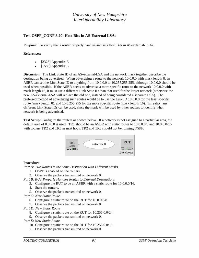
University of New Hampshire InterOperability Laboratory
Test OSPF_CONF.3.20: Host Bits in AS-External LSAs Purpose: To verify that a router properly handles and sets Host Bits in AS-external-LSAs. References:
• [2328] Appendix E • [1583] Appendix E
Discussion: The Link State ID of an AS-external-LSA and the network mask together describe the destination being advertised. When advertising a route to the network 10.0.0.0 with mask length 8, an ASBR can set the Link State ID to anything from 10.0.0.0 to 10.255.255.255, although 10.0.0.0 should be used when possible. If the ASBR needs to advertise a more specific route to the network 10.0.0.0 with mask length 16, it must use a different Link State ID than that used for the larger network (otherwise the new AS-external-LSA will replace the old one, instead of being considered a separate LSA). The preferred method of advertising such routes would be to use the Link ID 10.0.0.0 for the least specific route (mask length 8), and 10.0.255.255 for the more specific route (mask length 16). In reality, any different Link State IDs can be used, since the mask will be used by other routers to identify what network is being advertised. Test Setup: Configure the routers as shown below. If a network is not assigned to a particular area, the default area of 0.0.0.0 is used. TR1 should be an ASBR with static routes to 10.0.0.0/8 and 10.0.0.0/16 with routers TR2 and TR3 as next hops. TR2 and TR3 should not be running OSPF.
Backbone
network 0 RUTTR1ASBR
Procedure: Part A: Two Routes to the Same Destination with Different Masks
1. OSPF is enabled on the routers. 2. Observe the packets transmitted on network 0.
Part B: RUT Properly Handles Routes to External Destinations 3. Configure the RUT to be an ASBR with a static route for 10.0.0.0/16. 4. Start the routers. 5. Observe the packets transmitted on network 0.
Part C: New Static Route 6. Configure a static route on the RUT for 10.0.0.0/8. 7. Observe the packets transmitted on network 0.
Part D: New Static Route 8. Configure a static route on the RUT for 10.255.0.0/24. 9. Observe the packets transmitted on network 0.
Part E: New Static Route 10. Configure a static route on the RUT for 10.255.0.0/16. 11. Observe the packets transmitted on network 0.
ROUTING CONSORTIUM 97 OSPF Operations Test Suite

University of New Hampshire InterOperability Laboratory
Observable Results:
• In Part A, the RUT should have separate routes in its routing table for 10.0.0.0/8 and 10.0.0.0/16 with the next hop set to TR2 and TR3, respectively.
• In Part B, after the static route to 10.0.0.0/16 is configured on the RUT; the RUT should originate an AS-external-LSA for 10.0.0.0 (Link State ID can actually be anything from 10.0.0.0 to 10.255.255.255, but preferably 10.0.0.0) with netmask 255.255.0.0.
• In Part C, after the static route to 10.0.0.0/8 is configured on the RUT, the RUT should originate an AS-external-LSA for 10.0.0.0/16 with a different Link State ID than that used for 10.0.0.0/8.
• In Part D, after the static route to 10.255.0.0/24 is configured on the RUT, the RUT should originate an AS-external-LSA for 10.255.0.0/24, preferably using the Link State ID 10.255.0.0.
• In Part E, after the static route to 10.255.0.0/16 is configured on the RUT, the RUT needs to advertise 10.255.0.0/16 using a different Link State ID (or else change the one being used for 10.255.0.0/24). The preferable action, if it had used the Link State ID 10.255.0.0 for the previous AS-external-LSA, would be to advertise the 10.255.0.0/24 route with a new Link State ID, preferably 10.255.0.255. It can then advertise the route to 10.255.0.0/16 with the Link State ID 10.255.0.0.
Possible Problems: None.
ROUTING CONSORTIUM 98 OSPF Operations Test Suite

University of New Hampshire InterOperability Laboratory
GROUP 4: Route Calculation Overview The following tests verify the routing table building process of the OSPF Protocol. Discussion From the link state database, every router builds a shortest-path tree with itself as root. This is used to compute routes to destinations inside the OSPF domain and, with certain restrictions, outside the OSPF domain. References: RFC 1583 – Sections 12 and 16 RFC 2328 – Sections 12 and 16
ROUTING CONSORTIUM 99 OSPF Operations Test Suite
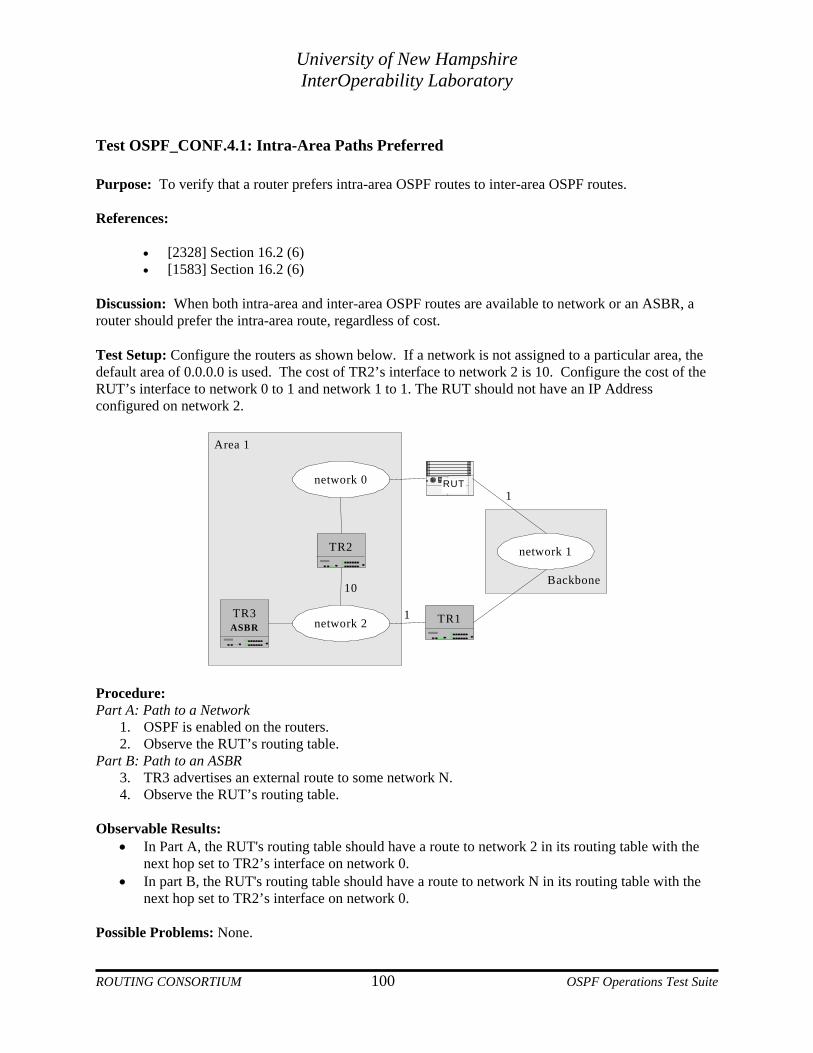
University of New Hampshire InterOperability Laboratory
Test OSPF_CONF.4.1: Intra-Area Paths Preferred Purpose: To verify that a router prefers intra-area OSPF routes to inter-area OSPF routes. References:
• [2328] Section 16.2 (6) • [1583] Section 16.2 (6)
Discussion: When both intra-area and inter-area OSPF routes are available to network or an ASBR, a router should prefer the intra-area route, regardless of cost. Test Setup: Configure the routers as shown below. If a network is not assigned to a particular area, the default area of 0.0.0.0 is used. The cost of TR2’s interface to network 2 is 10. Configure the cost of the RUT’s interface to network 0 to 1 and network 1 to 1. The RUT should not have an IP Address configured on network 2.
Backbone
network 0
network 2
network 1TR2
TR3ASBR
RUT
TR1
Area 1
1
1
10
Procedure: Part A: Path to a Network
1. OSPF is enabled on the routers. 2. Observe the RUT’s routing table.
Part B: Path to an ASBR 3. TR3 advertises an external route to some network N. 4. Observe the RUT’s routing table.
Observable Results:
• In Part A, the RUT's routing table should have a route to network 2 in its routing table with the next hop set to TR2’s interface on network 0.
• In part B, the RUT's routing table should have a route to network N in its routing table with the next hop set to TR2’s interface on network 0.
Possible Problems: None.
ROUTING CONSORTIUM 100 OSPF Operations Test Suite

University of New Hampshire InterOperability Laboratory
Test OSPF_CONF.4.2: Inter-Area Routes through Transit Areas Purpose: To verify that a router properly calculates inter-area routes when it is an ABR attached to a transit area. References:
• [2328] Sections 16.2 and 16.3 • [1583] Sections 16.2 and 16.3
Discussion: An OSPF router calculates inter-area routes by examining summary-network-LSAs or summary-ASBR-LSAs. Routers attached to a single area examine that area's summary-LSAs. If the router is an ABR, only backbone summary-LSAs are examined (or transit areas, as described below). To calculate the cost of an inter-area path to a destination N, a router combines the cost advertised in the corresponding summary-LSA with the cost of the best intra-area route to the advertising ABR. If multiple ABRs are advertising routes to the same destination, the router should use the path with the lowest total cost (intra-area cost to the ABR plus advertised cost).
If an ABR is attached to a transit area (an area with one or more virtual links in it), the router should also examine the summary-LSAs from that area for routing inter-area traffic in addition to the summary-LSAs in the backbone. Therefore, transit areas are the only non-backbone areas that may carry data traffic that neither originates nor terminates in the area itself. Transit area summary-LSAs are examined after the best inter-area route through the backbone is chosen. If any of the transit area summaries provide better routes to a network than a backbone route, the transit area path is used. If the router does not already have a route to the network described by the transit area summary, it should not install a route. In other words, a transit area summary may only be used if the network is reachable through the backbone as well. Test Setup: Configure the routers as shown below. If a network is not assigned to a particular area, the default area of 0.0.0.0 is used. Configure the RUT's costs to network 0 and network 1 to be 7 and 1, respectively. TR2’s cost to network 2 should be 3. All other costs should be 1. No virtual links should be configured. The RUT should not have a link to network 2.
ROUTING CONSORTIUM 101 OSPF Operations Test Suite
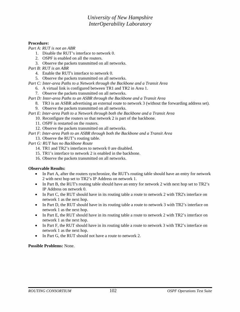
University of New Hampshire InterOperability Laboratory
Procedure: Part A: RUT is not an ABR
1. Disable the RUT’s interface to network 0. 2. OSPF is enabled on all the routers. 3. Observe the packets transmitted on all networks.
Part B: RUT is an ABR 4. Enable the RUT's interface to network 0. 5. Observe the packets transmitted on all networks.
Part C: Inter-area Paths to a Network through the Backbone and a Transit Area 6. A virtual link is configured between TR1 and TR2 in Area 1. 7. Observe the packets transmitted on all networks.
Part D: Inter-area Paths to an ASBR through the Backbone and a Transit Area 8. TR3 is an ASBR advertising an external route to network 3 (without the forwarding address set). 9. Observe the packets transmitted on all networks.
Part E: Inter-area Path to a Network through both the Backbone and a Transit Area 10. Reconfigure the routers so that network 2 is part of the backbone. 11. OSPF is restarted on the routers. 12. Observe the packets transmitted on all networks.
Part F: Inter-area Path to an ASBR through both the Backbone and a Transit Area 13. Observe the RUT’s routing table.
Part G: RUT has no Backbone Route 14. TR1 and TR2’s interfaces to network 0 are disabled. 15. TR1’s interface to network 2 is enabled in the backbone. 16. Observe the packets transmitted on all networks.
Observable Results:
• In Part A, after the routers synchronize, the RUT's routing table should have an entry for network 2 with next hop set to TR2’s IP Address on network 1.
• In Part B, the RUT's routing table should have an entry for network 2 with next hop set to TR2’s IP Address on network 0.
• In Part C, the RUT should have in its routing table a route to network 2 with TR2's interface on network 1 as the next hop.
• In Part D, the RUT should have in its routing table a route to network 3 with TR2’s interface on network 1 as the next hop.
• In Part E, the RUT should have in its routing table a route to network 2 with TR2’s interface on network 1 as the next hop.
• In Part F, the RUT should have in its routing table a route to network 3 with TR2’s interface on network 1 as the next hop.
• In Part G, the RUT should not have a route to network 2. Possible Problems: None.
ROUTING CONSORTIUM 102 OSPF Operations Test Suite

University of New Hampshire InterOperability Laboratory
Test OSPF_CONF.4.3: ASE Forwarding Addresses Purpose: To verify that a router properly uses the ForwardingAddress field in AS-external-LSAs. References:
• [2328] Sections 16.2 and 16.3 • [1583] Sections 16.2 and 16.3
Discussion: When originating AS-external-LSAs, the advertising ASBR can set the forwarding address to the IP Address of its own next hop if it resides on a network reachable through OSPF. This can eliminate unnecessary hops when other OSPF routers can reach the router specified by the forwarding address with less hops than if they were to first try to go to the ASBR, who would then forward it to its next hop. If the forwarding address is not set (it is left at 0.0.0.0), OSPF routers should choose their best route to the advertising ASBR as their route to the destination being advertised.
The forwarding address can be considered the Autonomous System's exit point for that particular destination. The router specified in the forwarding address is not itself running OSPF, yet it must be reachable through OSPF. So, when an ASBR originates an AS-external-LSA, it sets its own next hop as the forwarding address only if that next hop resides on a network that is part of the OSPF autonomous system (i.e. reachable via an intra-area or inter-area route). Test Setup: Configure the routers as shown below. If a network is not assigned to a particular area, the default area of 0.0.0.0 is used. TR1 is an ASBR with an external route to network 3 through a router on network 2. The AS-external-LSA should be configured with a type 1 cost of 1 and should have the forwarding address set to next hop’s IP Address on network 2. TR2 should not transmit any AS-external-LSAs at this time. The RUT should not have an IP Address configured on network 3.
Backbone
network 0
network 1
network 2
Area 1
5
1
1
2
3
TR1ASBR
TR2ASBR
RUT
Procedure: Part A: Originating Router Unreachable
1. OSPF is enabled on TR1 and TR2, and their databases are exchanged. TR1 transmits an AS-external-LSA with the forwarding address set.
2. OSPF is disabled on TR1. 3. Enable the RUT.
ROUTING CONSORTIUM 103 OSPF Operations Test Suite

University of New Hampshire InterOperability Laboratory
4. Observe the packets transmitted on all networks. Part B: Forwarding Address Reachable via Inter-area Route
5. OSPF is enabled on TR1. 6. Observe the RUT’s routing table.
Part C: Forwarding Address Reachable via Intra-area Route 7. TR1’s next hop for network 3 is configured to be a router on network 0. TR1 originates a new
AS-external-LSA for network 3 with the forwarding address set to a router on network 0. 8. Observe the RUT’s routing table.
Part D: No Preference for Intra or Inter-area Routes 9. TR2 is configured to transmit an AS-external-LSA for network 3 with type 1 metric 1 without the
forwarding address set. 10. Observe the RUT’s routing table.
Part E: Cost Change on Network 1 11. Configure the RUT’s cost to network 1 to be 3. 12. Observe the RUT’s routing table.
Observable Results:
• In Part A, the RUT should receive TR1’s AS-external-LSA from TR2 but should not install a route to network 3.
• In Part B, the RUT should have a route to network 3 with the next hop set to TR2’s IP Address on network 1. The RUT uses its least cost path to network 2 as the path to network 3.
• In Part C, the RUT should have a route to network 3 with the next hop set to the forwarding address of the ASE.
• In Part D, before the RUT’s cost to network 1 is changed to 3, the RUT should have a route to network 3 with the next hop set to TR2’s IP Address on network 1.
• In Part E, after the change, the RUT should have a route to network 3 with the next hop set to the forwarding address advertised in TR1’s AS-external-LSA.
Possible Problems: If the RUT has an IP Address on network 3, it will not install the OSPF route to the network.
ROUTING CONSORTIUM 104 OSPF Operations Test Suite

University of New Hampshire InterOperability Laboratory
Test OSPF_CONF.4.4: Intra-area Routes to an ASBR Purpose: To verify that when multiple intra-area paths to an ASBR are available, a router chooses the correct path. References:
• [2328] Sections 16.4 (3) and 16.4.1
Discussion: AS external routes are calculated by examining AS external LSAs. A router may have several paths to the ASBR that originated the LSA. When RFC 1583 compatibility is enabled, a router should choose the path with the lowest cost. If there are multiple paths with the lowest cost, a router should choose the path through the area with the largest Area ID.
When RFC 1583 compatibility is disabled, a router should prefer the lowest cost intra-area path through a non-backbone area. If there are multiple lowest cost paths through non-backbone areas, a router should choose the path with the largest Area ID. Test Setup: Configure the routers as shown below. If a network is not assigned to a particular area, the default area of 0.0.0.0 is used. Cases A and B should be run with RFC 1583 compatibility enabled. Cases C and D should be run with RFC 1583 compatibility disabled. TR1 is an ASBR advertising an AS external LSA.
Area 2
network 0 network 1
network 2
RUTTR1ASBR
Backbone Area 1
1
2
3
1
1
1
Procedure: Part A: One Least Cost Path with 1583Compatability Enabled
1. Configure the RUT’s costs to networks 0, 1 and 2 to be 1, 2 and 3, respectively. Configure RFC 1583 compatibility to be enabled.
2. OSPF is enabled on the routers. 3. Observe the packets transmitted on all networks.
Part B: Two Least Cost Paths with 1583Compatability Enabled 4. Configure the RUT’s cost to network 0 to be 2. 5. Observe the packets transmitted on all networks.
ROUTING CONSORTIUM 105 OSPF Operations Test Suite
University of New Hampshire InterOperability Laboratory
Part C: Least cost Path through the Backbone with 1583 Compatibility Disabled
6. Configure the RUT’s costs to networks 0, 1 and 2 to be 1, 2 and 3, respectively. Configure RFC 1583 compatibility to be disabled.
7. OSPF is enabled on the routers. 8. Observe the packets transmitted on all networks.
Part D: Two Equal Cost Paths through Non-Backbone Areas 9. Configure the RUT’s cost to network 1 to be 3. 10. Observe the packets transmitted on all networks.
Observable Results:
• In Part A, the RUT should choose the path with the least cost. It should have a route to the external network with TR1's interface on network 0 as the next hop.
• In Part B, since there are two paths with the least cost, the RUT should choose the path through the area with the largest Area ID. It should have a route to the external network with TR1’s interface on network 1 as the next hop.
• In Part C, the RUT should prefer intra-area paths through non-backbone areas. It should have a route to the external network with TR1's interface on network 1 as the next hop.
• In Part D, since there are two intra-area non-backbone paths with equal cost, the RUT should choose the path through the area with the largest Area ID. It should have a route to the external network with TR1’s interface on network 2 as the next hop.
Possible Problems: None.
ROUTING CONSORTIUM 106 OSPF Operations Test Suite
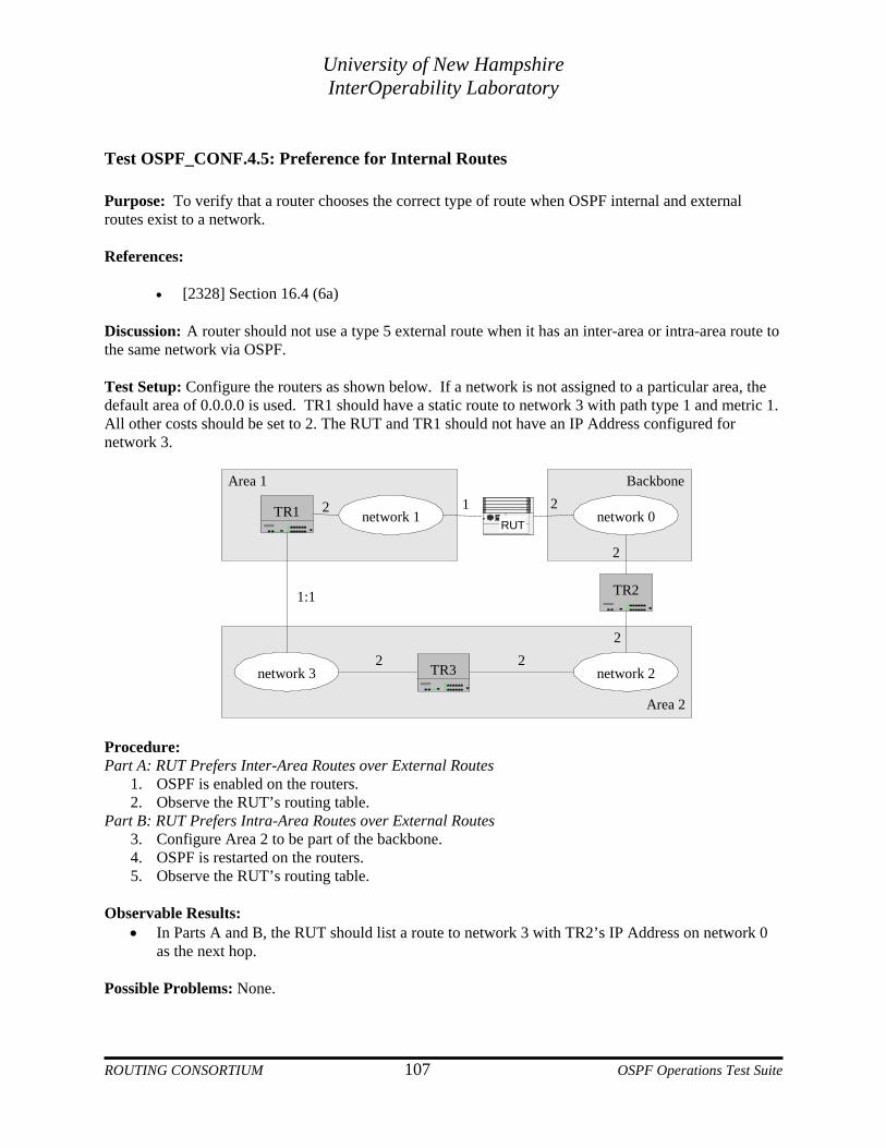
University of New Hampshire InterOperability Laboratory
Test OSPF_CONF.4.5: Preference for Internal Routes Purpose: To verify that a router chooses the correct type of route when OSPF internal and external routes exist to a network. References:
• [2328] Section 16.4 (6a) Discussion: A router should not use a type 5 external route when it has an inter-area or intra-area route to the same network via OSPF. Test Setup: Configure the routers as shown below. If a network is not assigned to a particular area, the default area of 0.0.0.0 is used. TR1 should have a static route to network 3 with path type 1 and metric 1. All other costs should be set to 2. The RUT and TR1 should not have an IP Address configured for network 3.
Area 2
TR1RUT
TR2
TR3
network 1 network 0
network 3 network 2
Area 1 Backbone
2 1 2
2
222
1:1
Procedure: Part A: RUT Prefers Inter-Area Routes over External Routes
1. OSPF is enabled on the routers. 2. Observe the RUT’s routing table.
Part B: RUT Prefers Intra-Area Routes over External Routes 3. Configure Area 2 to be part of the backbone. 4. OSPF is restarted on the routers. 5. Observe the RUT’s routing table.
Observable Results:
• In Parts A and B, the RUT should list a route to network 3 with TR2’s IP Address on network 0 as the next hop.
Possible Problems: None.
ROUTING CONSORTIUM 107 OSPF Operations Test Suite

University of New Hampshire InterOperability Laboratory
Test OSPF_CONF.4.6: Type 1 and Type 2 AS-External Routes Purpose: To verify that when choosing between multiple ASBRs advertising routes to the same destination, the router prefers type 1 routes over type 2. If only type 2 costs are present, a router always chooses the path to the ASBR advertising the lowest type 2 metric. References:
• [2328] Section 16.4 (6b) • [1583] Section 16.4 (6)
Discussion: AS-external-LSAs can be advertised with either type 1 or type 2 metrics. Type 1 metrics are comparable to the link state metric, while type 2 metrics are assumed to be larger than the cost of any intra-AS path. When multiple ASBRs are originating AS-external-LSAs to the same destination, a router should always prefer those using type 1 metrics to those using type 2 metrics. If multiple ASBRs are advertising type 2 metrics, the ASBR advertising the lowest type 2 metric is always chosen. Test Setup: Configure the routers as shown below. If a network is not assigned to a particular area, the default area of 0.0.0.0 is used. TR1 and TR2 are ASBRs with external routes to network 2 with path types 1 and 2, respectively. TR1’s type 1 metric is 10. TR2’s type 2 metric is 1. Configure the RUT's interfaces to network 0 and network 1 to have metrics 1 and 10, respectively.
AS 1 (OSPF)
network 0
network 1
RUT
TR1ASBR
TR2ASBR
network 2
1
10
2:1
1:10
Procedure: Part A: Type 1 and Type 2 Routes Available
1. OSPF is restarted on the routers. 2. Observe the packets transmitted on all networks.
Part B: Only Type 2 Routes Available 3. TR1 has an external route to network 2 is type 2 with metric 2. 4. Configure the RUT’s cost to network 0 to be 11. 5. Observe the packets transmitted on all networks.
ROUTING CONSORTIUM 108 OSPF Operations Test Suite

University of New Hampshire InterOperability Laboratory
Observable Results: • In Part A, the RUT’s routing table should have a route to network 2 with TR1’s interface on
network 1 as the next hop. • In Part B, the RUT’s routing table should have a route to network 2 with TR2’s interface on
network 0 as the next hop.
Possible Problems: None.
ROUTING CONSORTIUM 109 OSPF Operations Test Suite

University of New Hampshire InterOperability Laboratory
Test OSPF_CONF.4.7: Multiple ASBR’s through Intra-area Paths with 1583 Compatibility Enabled Purpose: To verify that a router properly chooses between multiple ASBRs when RFC 1583 compatibility is enabled. References:
• [2328] Section 16.4 (6d) Discussion: When RFC 1583 compatibility is enabled and intra-AS paths are available to multiple ASBRs, a router chooses the lowest cost path. If the destination was advertised in AS-external-LSAs with type 1 cost, a router adds the advertised cost to the cost of the path to the advertising ASBR. If the destination in question was advertised in AS-external-LSAs with the same type 2 cost, a router decides based on the intra-AS cost to the ASBRs. Test Setup: Configure the routers as shown below. If a network is not assigned to a particular area, the default area of 0.0.0.0 is used. Enable RFC 1583 compatibility on the RUT. TR1, TR2 and TR3 should be ASBRs advertising an AS-external-LSA to the same destination without the forwarding address set. Configure the RUT's costs to networks 0 and 1 and 2 to be 1, 10 and 20, respectively. The type and cost of the AS-external-LSAs for the TRs should be as shown below:
• TR1: type 1, cost 1 • TR2: type 1, cost 20 • TR3: type 1, cost 5
Area 1Area 2
network 0
network 2
network 1
TR1ASBR
TR3ASBR
RUT
TR2ASBR
Backbone
1
20
10
Procedure: Part A: Type 1 Metrics
1. OSPF is enabled on the routers. 2. Observe the RUT’s routing table.
Part B: Type 1 Metric changed 3. Configure the cost of TR1’s AS-external-LSA to be 25.
ROUTING CONSORTIUM 110 OSPF Operations Test Suite

University of New Hampshire InterOperability Laboratory
4. Observe the RUT’s routing table. Part C: Type 2 Metrics
5. The type and cost of the AS-external-LSAs should be type 2, cost 1 for all the TRs. 6. OSPF is restarted on the routers. 7. Observe the RUT’s routing table.
Part D: Type 2 Metric changed 8. Configure the cost of the RUT’s interface to network 0 to be 11. 9. Observe the RUT’s routing table.
Observable Results:
• In Part A, the RUT should have a route to the external network with TR1’s interface on network 0 as the next hop.
• In Part B, after the cost is changed, the RUT should have a route to the external network with TR3’s interface on network 2 as the next hop.
• In Part C, the RUT should have a route to the external network with TR1’s interface on network 0 as the next hop.
• In Part D, after the cost is changed, the RUT should have a route to the external network with TR2’s interface on network 1 as the next hop.
Possible Problems: None.
ROUTING CONSORTIUM 111 OSPF Operations Test Suite

University of New Hampshire InterOperability Laboratory
Test OSPF_CONF.4.8: Multiple ASBRs through Intra-area Paths with 1583Compatibility Disabled Purpose: To verify that a router properly chooses between multiple ASBRs reachable via intra-area non-backbone routes when RFC 1583 compatibility is disabled. References:
• [2328] Sections 16.4 (6c), (6d) and 16.4.1 (first bullet) Discussion: When multiple intra-AS paths are available to multiple ASBRs, a router prefers those ASBRs reachable through non-backbone areas. If, after this decision, there are still multiple ASBRs to choose from, a router decides based on cost. If the destination in question was advertised in AS-external-LSAs with type 1 cost, a router adds the advertised cost to the cost of the path to the advertising ASBR. If the destination in question was advertised in AS-external-LSAs with the same type 2 cost, a router decides based on the cost to the ASBRs. Test Setup: Configure the routers as shown below. If a network is not assigned to a particular area, the default area of 0.0.0.0 is used. TR1, TR2 and TR3 should be ASBRs advertising an AS-external-LSA to the same destination without the forwarding address set. Configure the RUT's costs to networks 0 and 1 and 2 to be 1, 10 and 20, respectively. The type and cost of the AS-external-LSAs for the TRs should be as shown below:
• TR1: type 1, cost 1 • TR2: type 1, cost 20 • TR3: type 1, cost 5
Area 1Area 2
network 0
network 2
network 1
TR1ASBR
TR3ASBR
RUT
TR2ASBR
Backbone
1
20
10
Procedure: Part A: Least Cost Path through Backbone
1. Disable RFC 1583 compatibility on the RUT. 2. Start TR1, TR2 and the RUT (TR3 should not be running). 3. Observe the RUT’s routing table.
ROUTING CONSORTIUM 112 OSPF Operations Test Suite

University of New Hampshire InterOperability Laboratory
Part B: Multiple Non-Backbone Paths with Type 1 Metrics
4. TR3 is enabled. 5. Observe the RUT’s routing table.
Part C: Multiple Non-Backbone Paths with Type 2 Metrics 6. The type and cost of the AS-external-LSAs should be type 2, cost 1 for all the TRs. 7. OSPF is restarted on the routers. 8. Observe the RUT’s routing table.
Part D: Network 2 cost change 9. Configure the cost of the RUT’s interface to network 2 to 5. 10. Observe the RUT’s routing table.
Observable Results:
• In Part A, the RUT should have a route to the external network with TR2’s interface on network 1 as the next hop.
• In Part B, the RUT should have a route to the external network with TR3’s interface on network 2 as the next hop.
• In Part C, the RUT should have a route to the external network with TR2’s interface on network 1 as the next hop.
• In Part D, after the cost is changed, the RUT should have a route to the external network with TR3’s interface on network 2 as the next hop.
Possible Problems: None.
ROUTING CONSORTIUM 113 OSPF Operations Test Suite

University of New Hampshire InterOperability Laboratory
Test OSPF_CONF.4.9: Multiple ASBRs Reachable via Backbone Areas with 1583Compatability Purpose: To verify that a router properly chooses between multiple ASBRs reachable through inter-area or intra-area backbone routes when RFC 1583 compatibility is enabled or disabled. References:
• [2328] Sections 16.4 (6c) and (6d)
Discussion: When intra-AS paths are available to multiple ASBRs, a router chooses the lowest cost path. If the destination was advertised in AS-external-LSAs with type 1 cost, a router adds the advertised cost to the cost to the advertising ASBR. If the destination in question was advertised in AS-external-LSAs with the same type 2 cost, a router decides based on the intra-AS cost to the ASBRs. Test Setup: Configure the routers as shown below. If a network is not assigned to a particular area, the default area of 0.0.0.0 is used. Enable 1583 compatibility on the RUT. TR3 and TR4 are ASBRs advertising AS-external-LSAs with type 1 metric to the same destination.
Area 1
network 0 network 1
network 2
RUTTR2
TR1
TR3ASBR
TR4ASBR
Backbone1
10
Procedure: Part A: Inter-Area Path Least Cost with Type 1 Metrics
1. The cost of TR3’s type 1 ASE is 20 and the cost of TR4’s type 1 ASE is 5. 2. OSPF is enabled on the routers. 3. Observe the RUT’s routing table.
Part B: Intra-Area Path Least Cost with Type 1 Metrics 4. The cost of TR4’s type 1 ASE is 12. 5. Observe the RUT’s routing table.
Part C: Inter-Area Path Least Cost with Type 2 Metrics 6. TR3 and TR4 are set to advertise the external destination with the same type 2 metric. The cost
of TR1’s interface to network 1 is 11. 7. Observe the RUT’s routing table.
ROUTING CONSORTIUM 114 OSPF Operations Test Suite

University of New Hampshire InterOperability Laboratory
Part D: Intra-Area Path Least Cost with Type 2 Metrics 8. The cost of TR1’s interface to network 1 is 1. 9. Observe the RUT’s routing table.
Observable Results:
• In Parts A and C, the RUT should have a route to the external network with TR2’s network 0 IP Address as the next hop.
• In Parts B and D, the RUT should have a route to the external network with TR1’s network 0 IP Address as the next hop.
Possible Problems: None.
ROUTING CONSORTIUM 115 OSPF Operations Test Suite

University of New Hampshire InterOperability Laboratory
Test OSPF_CONF.4.10: Multiple ASBRs Reachable via Backbone Areas without 1583Compatability Purpose: To verify that a router properly chooses between multiple ASBRs reachable through inter-area or intra-area backbone routes when RFC 1583 compatibility is enabled or disabled. References:
• [2328] Sections 16.4 (6c) and (6d)
Discussion: When intra-AS paths are available to multiple ASBRs, a router chooses the lowest cost path. If the destination was advertised in AS-external-LSAs with type 1 cost, a router adds the advertised cost to the cost to the advertising ASBR. If the destination in question was advertised in AS-external-LSAs with the same type 2 cost, a router decides based on the intra-AS cost to the ASBRs. Test Setup: Configure the routers as shown below. If a network is not assigned to a particular area, the default area of 0.0.0.0 is used. Disable 1583 compatibility on the RUT. TR3 and TR4 are ASBRs advertising AS-external-LSAs with type 1 metric to the same destination.
Area 1
network 0 network 1
network 2
RUT TR2
TR1
TR3ASBR
TR4ASBR
Backbone1
10
Procedure: Part A: Inter-Area Path Least Cost with Type 1 Metrics
1. The cost of TR3’s type 1 ASE is 20 and the cost of TR4’s type 1 ASE is 5. 2. OSPF is enabled on the routers. 3. Observe the RUT’s routing table.
Part B: Intra-Area Path Least Cost with Type 1 Metrics 4. The cost of TR4’s type 1 ASE is 12. 5. Observe the RUT’s routing table.
Part C: Inter-Area Path Least Cost with Type 2 Metrics 6. TR3 and TR4 are set to advertise the external destination with the same type 2 metric. 7. The cost of TR1’s interface to network 1 is 11. 8. Observe the RUT’s route table.
ROUTING CONSORTIUM 116 OSPF Operations Test Suite

University of New Hampshire InterOperability Laboratory
Part D: Intra-Area Path Least Cost with Type 2 Metrics 9. The cost of TR1’s interface to network 1 is 1. 10. Observe the RUT’s routing table.
Observable Results:
• In Parts A and C, the RUT should have a route to the external network with TR2’s network 0 IP Address as the next hop.
• In Parts B and D, the RUT should have a route to the external network with TR1’s network 0 IP Address as the next hop.
Possible Problems: None.
ROUTING CONSORTIUM 117 OSPF Operations Test Suite

University of New Hampshire InterOperability Laboratory
Group 5: Configuration and Formatting Overview The following tests verify that necessary OSPF parameters are configurable and that OSPF packets are properly formatted. Discussion An OSPF router must allow the configuration of certain parameters: area parameters, interface parameters, type of external routes etc. OSPF packets must be properly formatted in order for the routers to “understand” each other. References: RFC 1583 – Sections 2, 3, 4 and 12; Appendixes C and D RFC 2328 – Sections 2, 3, 4 and 12; Appendixes C and D
ROUTING CONSORTIUM 118 OSPF Operations Test Suite
University of New Hampshire InterOperability Laboratory
Test OSPF_CONF.5.1: Area Parameters Purpose: To verify that the area parameters listed below are configurable. References:
• [2328] Appendix C.2 • [1583] Appendix C.2
Discussion: The following area parameters must be configurable:
• Area ID • List of component address ranges: each address range includes a [address, mask] pair and a status
indication of either Advertise or DoNotAdvertise. • External routing capability: whether or not the area is a stub area. • StubDefaultCost: if the area is a stub area, and the router is an ABR, then the StubDefaultCost
indicates the cost of the default summary link that the router should advertise into the area. All these are implicitly tested by other tests. They are here only as a checklist. Possible Problems: None.
ROUTING CONSORTIUM 119 OSPF Operations Test Suite

University of New Hampshire InterOperability Laboratory
Test OSPF_CONF.5.2: Interface Parameters Purpose: To verify that the interface parameters listed below are configurable. References:
• [2328] Appendix C.3 • [1583] Appendix C.3
Discussion: The following interface parameters must be configurable:
• IP interface address • IP interface mask • Area ID • Interface output cost • RxmtInterval • InfTransDelay • Router Priority (except for point-to-point) • HelloInterval • RouterDeadInterval • AuType • Authentication Key
All these are implicitly tested by other tests. They are here only as a checklist. Possible Problems: None.
ROUTING CONSORTIUM 120 OSPF Operations Test Suite

University of New Hampshire InterOperability Laboratory
Test OSPF_CONF.5.3: Router LSA Bits Purpose: To verify that a router properly sets the E, B and V bits in its router-LSAs. References:
• [2328] Section 12.4.1 • [1583] Section 12.4.1
Discussion: A router should set the B bit in its router-LSAs whenever it is an ABR. A router should set the E bit in its non-stub area router-LSAs when it is an AS boundary router. The E bit should never be set in router-LSAs for a stub area. The V bit is set if a router is the endpoint of a virtual link and is only sent in router-LSAs for the associated transit area. Test Setup: Configure the routers as shown below. If a network is not assigned to a particular area, the default area of 0.0.0.0 is used. Configure the RUT to be an ASBR advertising an AS external LSA. Area 2 should be a stub area.
Area 2 (Stub)
Backbone
Area 1
network 0
network 1
network 2
network 3
TR2
TR1
RUTASBR
Procedure: Part A: E-Bit Set Properly
1. OSPF is enabled on the routers. 2. Observe the packets transmitted on all networks.
Part B: B-Bit Set Properly 3. Observe the RUT’s router-LSA.
Part C: V-Bit Set Properly 4. Configure a virtual link between TR1 and the RUT through Area 1. 5. OSPF is restarted on the routers. 6. Wait for the virtual adjacency to form, observe the packets transmitted on all networks.
Part D: RUT Drops E-Bit 7. Configure the RUT to be a non-ASBR. 8. OSPF is restarted on the routers. 9. Observe the packets transmitted on all networks.
Part E: No Bits Set 10. Disable the RUT’s interfaces to Area 0 and Area 2 (including the virtual link).
ROUTING CONSORTIUM 121 OSPF Operations Test Suite
University of New Hampshire InterOperability Laboratory
11. A virtual link is configured between TR1 and TR2. 12. OSPF is restarted on the routers. 13. Observe the packets transmitted on all networks.
Observable Results:
• In Part A, the RUT should set the E bit in its router-LSAs for Areas 0 and 1, but not for Area 2. • In Part B, the RUT should set the B bit in all its router-LSAs. • In Part C, the RUT should only set the V bit in its router-LSAs for Area 1. It should still set the E
bit in its router-LSAs for Areas 0 and 1 and the B bit in all router-LSAs. • In Part D, the RUT should not set the E bit in any of its LSAs. • In Part E, the RUT should not set any bits in its router-LSA for Area 1.
Possible Problems: None.
ROUTING CONSORTIUM 122 OSPF Operations Test Suite

University of New Hampshire InterOperability Laboratory
Test OSPF_CONF.5.4: IP Header Fields Purpose: To verify that a router properly sets the TOS and Precedence fields in the IP header.
References:
• [2328] Section 4.3 • [1583] Section 4.3
Discussion: Routing protocol packets should be sent with the IP TOS field set to 0. All OSPF packets should be given preference over regular IP data traffic. This is accomplished by setting their IP Precedence field to the value Internetwork Control (0xc0). Test Setup: Configure the routers as shown below. If a network is not assigned to a particular area, the default area of 0.0.0.0 is used.
RUT network 0
Procedure: Part A: IP TOS
1. Enable OSPF on the RUT. 2. Observe the IP TOS field in the RUT’s Hello packet.
Observable Results:
• The IP TOS field should be set to 0xC0. Possible Problems: None.
ROUTING CONSORTIUM 123 OSPF Operations Test Suite

University of New Hampshire InterOperability Laboratory
Test OSPF_CONF.5.5: No Virtual Links in Stub Areas Purpose: To verify that a router does not allow a virtual link to be configured in a stub area. References:
• [2328] Section 3.6 • [1583] Section 3.6
Discussion: Stub areas are not capable of supporting transit traffic because stub areas have a reduced link state database. This restricts virtual links from being configured through stub areas. Test Setup: Configure the routers as shown below. If a network is not assigned to a particular area, the default area of 0.0.0.0 is used. Area 1 should be a stub area. A virtual link should be configured between the RUT and TR1. The RUT may deny this configuration, as it should.
Area 1(Stub)
Backbone
network 0
network 1
RUTTR1
virtual link
Procedure: Part A: Virtual Link not Configurable through a Stub Area
1. OSPF is enabled on the routers. 2. Observe the packets transmitted on all networks and over the virtual link.
Observable Results:
• In Part A, the RUT should not allow the user to configure the virtual link through Area 1. If the user is allowed to configure the virtual link, the RUT should not transmit unicast Hello packets to TR1 in Area 1. The virtual adjacency should not form.
Possible Problems: None.
ROUTING CONSORTIUM 124 OSPF Operations Test Suite

University of New Hampshire InterOperability Laboratory
Test OSPF_CONF.5.6: Simple Authentication with RFC 2328 Purpose: To verify that authentication type and additional authentication data is configurable on a per-interface basis. References:
• [2328] Appendix D
Discussion: The OSPF packet header includes an authentication type field and a 64-bit data field for use by the appropriate authentication scheme. The authentication type is configurable on a per-interface basis. There are 3 schemes available for use:
• AuType 0 (null authentication) • AuType 1 (simple password) • AuType 2 (cryptographic authentication)
For AuType 1 and 2 the password is configurable on a per-interface basis. For a virtual link, a password in addition to and independent of the password used in the transit area must be used. Test Setup: Configure the routers as shown below. If a network is not assigned to a particular area, the default area of 0.0.0.0 is used. Configure the RUT with AuType 0 in Area 0 and AuType 1 in Area 1. TR1 should set AuType 0 in Area 0, and AuType 1 in Area 1. TR2 should set AuType 1 in Area 0, and AuType 0 in Area 1. The same password should be configured on the following interfaces:
• RUT on network 1; • TR1 on network 1; • TR2 on network 0.
network 0
network 1
RUTTR1 TR2
Backbone
Area 1 Procedure: Part A: AuType and Password Configurable per Interface
1. The RUT is configured as described above. Part B: AuType and Password Configurable on Virtual Links
2. Configure a virtual link between RUT and TR1 through Area 1, with AuType 1.
ROUTING CONSORTIUM 125 OSPF Operations Test Suite
University of New Hampshire InterOperability Laboratory
Part C: RUT Properly Becomes Adjacent to Routers with Same AuType and Password
and network 1. Par
7. rted on the routers. and network 1.
Obs
• In Part A, the RUT should allow the user to configure the AuType on its interface to network 0. UT should allow the user to configure the AuType for the virtual link.
Possibl
3. OSPF is enabled on the routers. 4. Wait for the adjacencies to form. Observe the packets transmitted on network 0t D: RUT with AuType 2 5. Configure the RUT and TR2 with AuType 2 and the same password on their interfaces to
network 0. 6. Reconfigure the virtual link with AuType 2.
OSPF is resta8. Observe the packets transmitted on network 0
ervable Results:
• In Part B, the R• In Part C, the RUT should become a neighbor with TR1 on both network 0 and network 1. The
RUT should not become a neighbor with TR2. The virtual link should become active. • In Part D, after the AuType is changed, the RUT should become a neighbor with TR2, but not
with TR1. The virtual link should become active.
e Problems: None.
ROUTING CONSORTIUM 126 OSPF Operations Test Suite

University of New Hampshire InterOperability Laboratory
Test OSPF_CONF.5.7: MD5 Authentication Purpose: To verify that Authentication Type can be set to MD5 or cryptographic. References:
• [2328] Appendix D
Discussion: When an OSPF packet has been received on an interface, it must be authenticated. The authentication procedure is indicated by the setting of Autype in the standard OSPF packet header, which matches the setting of Autype for the receiving OSPF interface. MD5 is run over the concatenation of the OSPF packet, secret key, pad and length fields, producing a 16-byte message digest. The MD5 digest is written over the OSPF key. The digest is not counted in the OSPF packet’s length field, but is included in the packet’s IP length field. Any trailing pad or length fields beyond the digest are not counted or transmitted. Test Setup: Configure the routers as shown below. If a network is not assigned to a particular area, the default area of 0.0.0.0 is used. Configure the RUT with AuType 2 on its interface to network 0 and AuType 0 on its interface to network 1. Configure TR1 with AuType 2 on its interface to network0 and AuType 0 on its interface to network 1. The RUT and TR1 should be configured with the same Key ID and password on network 0.
Area 1
Backbone
network 0
network 1
RUTTR1
virtual link
Procedure: Part A: AuType 2 on Interfaces
1. The RUT is configured as described above. Part B: AuType 2 over Virtual Links
2. Configure a virtual link between the RUT and TR1 over Area 1. 3. Configure both ends of the virtual link to have AuType 2 with the same password and Key ID.
Part C: RUT Forms Adjacencies 4. OSPF is enabled on the routers. 5. Observe the packets transmitted on network 0 and network 1.
Part D: Different Passwords 6. Configure TR1 to have a different password, but same Key ID as the RUT on its interface to
network 0.
ROUTING CONSORTIUM 127 OSPF Operations Test Suite
University of New Hampshire InterOperability Laboratory
7. OSPF is restarted on the routers. 8. Observe the packets transmitted on network 0.
Part E: Different Key IDs 9. Configure TR1 to have the same password as the RUT, but with a different Key ID. 10. OSPF is restarted on the routers. 11. Observe the packets transmitted on network 0,
Observable Results:
• In Part A, the RUT should allow AuthenticationType cryptographic to be configured on its interface to network 0.
• In Part B, the RUT should allow AuthenticationType cryptographic to be configured over the virtual link.
• In Part C, RUT and TR1 should become adjacent on network 0 and over the virtual link. • In Parts D and E, the RUT and TR1 should not become neighbors on network 0.
Possible Problems: None.
ROUTING CONSORTIUM 128 OSPF Operations Test Suite

University of New Hampshire InterOperability Laboratory
Test OSPF_CONF.5.8: Incorrect Checksums Purpose: To verify the handling of the Checksum field. References:
• [2328] Section 12.1.7 • [1583] Section 12.1.7
Discussion: When LSAs are received, the Checksum field is verified. If the Checksum field is invalid, the LSA must be discarded and it must not be acknowledged. Test Setup: Configure the routers as shown below. If a network is not assigned to a particular area, the default area of 0.0.0.0 is used. Configure the routers appropriately, where TR1 is a packet generator simulating a router
network 0
RUTTR1
Procedure: Part A: Invalid Checksum
1. OSPF is enabled on the routers. 2. TR1 transmits an LSA with an invalid checksum. 3. Observe the packets transmitted on network 0 and observe the RUT’s link state database.
Observable Results:
• In Part A, the RUT should not acknowledge the LSA. The RUT should not install the LSA in its link state database.
Possible Problems: None.
ROUTING CONSORTIUM 129 OSPF Operations Test Suite

University of New Hampshire InterOperability Laboratory
Test OSPF_CONF.5.9: #Advertisements Field Purpose: To verify the handling of the #Advertisements field in LS Update packets. References:
• [2328] Appendix A.4.1 • [1583] Appendix A.4.1
Discussion: The #Advertisements field in the LS Update header shows how many LSAs are included in the LS Update packet. If the actual number of LSAs is less than #Advertisements, a router should:
• either drop the packet • or process only the LSAs contained in the packet.
Version # 4 Packet Length Router ID Area ID
Checksum AuType Authentication Authentication
#LSAs
LSAs
Test Setup: Configure the routers as shown below. If a network is not assigned to a particular area, the default area of 0.0.0.0 is used. Configure the routers appropriately, where TR1 is a packet generator simulating a router
network 0
RUTTR1
Procedure: Part A: #Advertisement Field
1. OSPF is enabled on the routers. 2. TR1 transmits an LS Update packet with less LSAs than #Advertisements. 3. Observe the RUT’s link state database.
Observable Results:
• In Part A, the RUT should not crash. The RUT may have installed the LSAs contained in the packet in its link state database.
ROUTING CONSORTIUM 130 OSPF Operations Test Suite

University of New Hampshire InterOperability Laboratory
Possible Problems: None.
ROUTING CONSORTIUM 131 OSPF Operations Test Suite
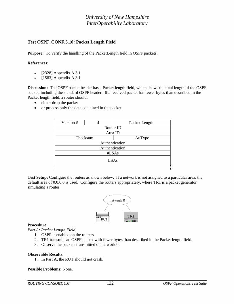
University of New Hampshire InterOperability Laboratory
Test OSPF_CONF.5.10: Packet Length Field Purpose: To verify the handling of the PacketLength field in OSPF packets. References:
• [2328] Appendix A.3.1 • [1583] Appendix A.3.1
Discussion: The OSPF packet header has a Packet length field, which shows the total length of the OSPF packet, including the standard OSPF header. If a received packet has fewer bytes than described in the Packet length field, a router should:
• either drop the packet • or process only the data contained in the packet.
Version # 4 Packet Length Router ID Area ID
Checksum AuType Authentication Authentication
#LSAs
LSAs
Test Setup: Configure the routers as shown below. If a network is not assigned to a particular area, the default area of 0.0.0.0 is used. Configure the routers appropriately, where TR1 is a packet generator simulating a router
network 0
RUTTR1
Procedure: Part A: Packet Length Field
1. OSPF is enabled on the routers. 2. TR1 transmits an OSPF packet with fewer bytes than described in the Packet length field. 3. Observe the packets transmitted on network 0.
Observable Results:
1. In Part A, the RUT should not crash. Possible Problems: None.
ROUTING CONSORTIUM 132 OSPF Operations Test Suite

University of New Hampshire InterOperability Laboratory
Test OSPF_CONF.5.11: LSA Header Length Field Purpose: To verify the handling of the Length field in the LSA header. References:
• [2328] Appendix A.4.1 • [1583] Appendix A.4.1
Discussion: The LSA header has a Length field, which describes the total length, in bytes, of the LSA, including the LSA header. If a received LSA is smaller than the length described in the LSA header, the LSA should be discarded. Test Setup: Configure the routers as shown below. If a network is not assigned to a particular area, the default area of 0.0.0.0 is used. Configure the routers appropriately, where TR1 is a packet generator simulating a router
network 0
RUTTR1
Procedure: Part A: Length Field
1. OSPF is enabled on the routers. 2. TR1 transmits an LSA shorter than the length described in the LSA header. 3. Observe the packets transmitted on network 0.
Observable Results:
• In Part A, the RUT should not crash. Possible Problems: None.
ROUTING CONSORTIUM 133 OSPF Operations Test Suite

University of New Hampshire InterOperability Laboratory
Test OSPF_CONF.5.12: Router LSA #Links Field Purpose: To verify the handling of the #Links field in router-LSAs. References:
• [2328] Appendix A.4.2 • [1583] Appendix A.4.2
Discussion: The router-LSA header has a #links field, which describes how many links are included in the LSA. If the #links field indicates more links than will fit in the LSA, a router should not attempt to access memory past the end of the LSA. Test Setup: Configure the routers as shown below. If a network is not assigned to a particular area, the default area of 0.0.0.0 is used. Configure the routers appropriately, where TR1 is a packet generator simulating a router
network 0
RUTTR1
Procedure: Part A: #Links Field
1. OSPF is enabled on the routers. 2. TR1 transmits a router-LSA with the #links field indicating more links than the actual number of
links in the LSA. 3. Observe the RUT’s link state database.
Observable Results:
• In Part A, the RUT should not crash. The corresponding LSA in the RUT’s link state database should have only the links listed in the received LSA
Possible Problems: None.
ROUTING CONSORTIUM 134 OSPF Operations Test Suite

University of New Hampshire InterOperability Laboratory
Test OSPF_CONF.5.13: Router LSA #TOS Field Purpose: To verify the handling of the #TOS field in router-LSAs. References:
• [2328] Appendix A.4.2 • [1583] Appendix A.4.2
Discussion: The router-LSA entry for a link has a #TOS field, which describes the number of different TOS metrics given for the link. If the #TOS field indicates more TOS metrics than will fit in the LSA, a router should not attempt to access memory past the end of the LSA. Test Setup: Configure the routers as shown below. If a network is not assigned to a particular area, the default area of 0.0.0.0 is used. Configure the routers appropriately, where TR1 is a packet generator simulating a router
network 0
RUTTR1
Procedure: Part A: #TOS Field
1. OSPF is enabled on the routers. 2. TR1 transmits a router-LSA with a #TOS field indicating more TOS metrics than the actual
number of TOS metrics in the LSA. 3. Observe the RUT’s link state database.
Observable Results:
• In Part A, the RUT should not crash. The corresponding LSA in the RUT’s link state database should have only the TOS metrics listed in the received LSA.
Possible Problems: None.
ROUTING CONSORTIUM 135 OSPF Operations Test Suite