Embed Size (px)
Citation preview
© 2016 Higher Mapping Solutions & RouteWare
A Network Analysis System forMapInfo Professional
RouteFinder 5.02 for MapInfo

IContents
© 2016 Higher Mapping Solutions & RouteWare
Table of Contents
Part I Introduction 3
................................................................................................................................... 31 System Requirements
................................................................................................................................... 42 32 / 64-bit version
................................................................................................................................... 53 Installation Notes
................................................................................................................................... 64 Quick Start Guide
................................................................................................................................... 115 List of network files
................................................................................................................................... 126 Support
................................................................................................................................... 127 History
................................................................................................................................... 138 Changes from RouteFinder 4
................................................................................................................................... 139 Updating from RouteFinder 4
................................................................................................................................... 1410 License Agreement
................................................................................................................................... 1511 SDK
................................................................................................................................... 1512 Acknowledgements
Part II Basic Functions 19
................................................................................................................................... 191 Creating a Network
................................................................................................................................... 232 Road Speed Options
................................................................................................................................... 253 Route Options
................................................................................................................................... 314 Drive Time Options
................................................................................................................................... 365 Travelling Salesman Options
................................................................................................................................... 376 Program Options
................................................................................................................................... 397 Open User Folder
Part III Interactive Tools 43
................................................................................................................................... 431 Route
................................................................................................................................... 442 Travelling Salesman
................................................................................................................................... 453 Link Isochrone
................................................................................................................................... 464 Simple Isochrone
................................................................................................................................... 475 Voronoi Isochrone
................................................................................................................................... 486 Service Area
................................................................................................................................... 497 Update Point File
................................................................................................................................... 508 Traffic Volume
................................................................................................................................... 529 Clear Current Result
Part IV Batch Jobs 55
RouteFinder 5.02 for MapInfoII
© 2016 Higher Mapping Solutions & RouteWare
................................................................................................................................... 551 Distance Matrix
................................................................................................................................... 582 Nearest N Centres
................................................................................................................................... 613 Route Pairs
................................................................................................................................... 644 Route Pairs by Coordinate
................................................................................................................................... 665 Travelling Salesman from table
................................................................................................................................... 696 Batch TSP Routes from table
................................................................................................................................... 717 Select Locations
................................................................................................................................... 738 Route on a Joined Table by ID
................................................................................................................................... 759 Allocate Point to Network
................................................................................................................................... 7710 Drive Times / Service Area
................................................................................................................................... 8011 Drive Time from Column
Part V Restrictions 85
................................................................................................................................... 851 Import Turn File
................................................................................................................................... 872 Displaying One Way Streets
................................................................................................................................... 883 No Turn
................................................................................................................................... 894 One-Way
................................................................................................................................... 905 Set Avoids
................................................................................................................................... 916 Height
................................................................................................................................... 927 Width
................................................................................................................................... 938 Weight
................................................................................................................................... 949 Change Road Speed
................................................................................................................................... 9510 Close Road
................................................................................................................................... 9611 Show Restrictions
................................................................................................................................... 9712 Show Closed Roads
................................................................................................................................... 9713 Delete
................................................................................................................................... 9914 Save
Part VI Network Analysis 103
................................................................................................................................... 1031 Add Node Layer
................................................................................................................................... 1042 Close Nodes
................................................................................................................................... 1053 Node-Link Check
................................................................................................................................... 1074 Overpasses Check
................................................................................................................................... 1085 Detect Cul-De-Sac
................................................................................................................................... 1086 Select Subnets
................................................................................................................................... 1097 Select Subnets (Extended)
................................................................................................................................... 1108 Select Bridges

IIIContents
© 2016 Higher Mapping Solutions & RouteWare

Introduction
Part I

3Introduction
© 2016 Higher Mapping Solutions & RouteWare
1 Introduction
RouteFinder 5.02
Welcome to RouteFinder, a network analysis system for MapInfo Professional.
RouteFinder offers a lot of functionality for routing:
Point-2-point routingTravelling salesman optimizationDistance matricesNearest N calculationsRoute pairsIsochrones - 3 typesTraffic volumesService areasTopological checks of the networketc.
This version is built on top of the RW Net 4 library and as such you cannot use networksfrom earlier versions of RouteFinder. However it is normally just a case of creating anetwork in this version. Please read the chapter on Changes from RouteFinder Version 4
You can get up and running quickly by reading the Quick Start Guide
1.1 System Requirements
RouteFinder for MapInfo:MapInfo 10.0 - 15.0 (32-bit).MapInfo 15.2.2 or greater (64-bit).
Hard disk requirement17 MB with sample data.
Operating SystemThe application has been tested on Windows 7, 8, 8.1 and 10 (64-bit).
Access rightsThe user needs to have admin rights to install the software.
Processor speedDepending on the kind of tasks, you are performing with RouteFinder; a fast processor maybe a good idea.Especially large Batch Route jobs requires some processing time, but also some of thetopology checking functions do take some time.
RAM
4 RouteFinder 5.02 for MapInfo
© 2016 Higher Mapping Solutions & RouteWare
Depending on the size of the street networks you are going to work with, you may needadditional RAM.As a rule of thumb each record in the street database requires a 50-150 bytes.
An example: A street network with 1,000,000 links will need a minimum of 50 MB RAM tostore the network.When adding weight / width / height / road names / external ID etc. it may increase to 150MB.
Doing Voronoi based calculations may easily require 2-3 times more RAM than mentionedabove. This includes Voronoi Drive Time / Distance and Service Area .
1.2 32 / 64-bit version
RouteFinder 5 is available in two versions, for 32 and 64-bit MapInfo.
They provide the same functionality and use the same data files for the routing.They can both be installed and also share the same license file.
But you should only be running one of them at a time, since they share the user folder .
The 32-bit version can not use extended TAB files, since they can not be opened in thatversion of MapInfo Professional.
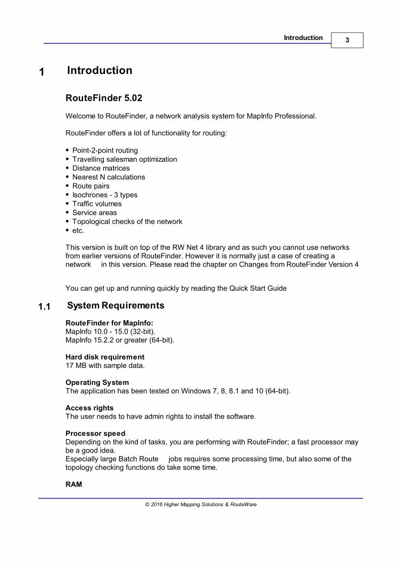
The documentation shows screen dumps from the 64-bit version only, but the menustructure is the same:
32 bit user interface
5Introduction
© 2016 Higher Mapping Solutions & RouteWare
This is made of the traditional menus and buttons.
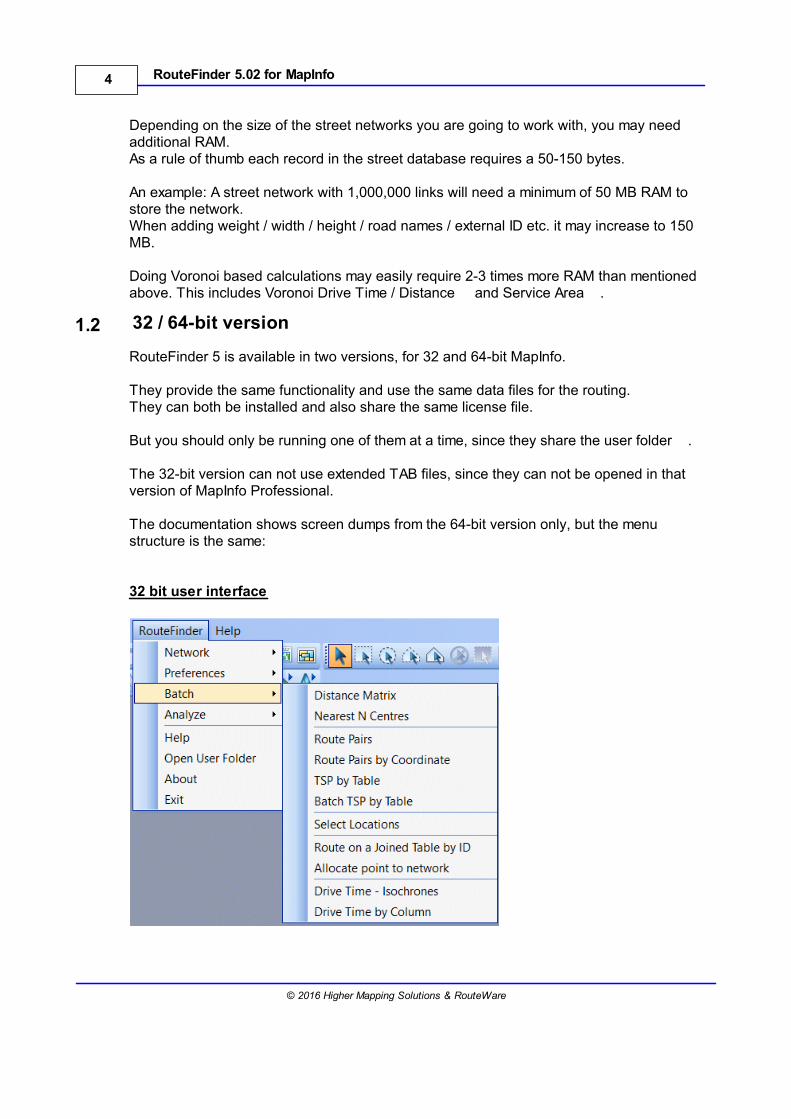
64 bit user interface
This uses the new style Ribbon interface with button and drop down menus.
1.3 Installation Notes
Installation stepsYou should install MapInfo Professional before you install RouteFinder.If a previous version of RouteFinder has been installed, you can leave it in place. Just makesure you install into different directories.Now install RouteFinder by running the setup application.After you have installed RouteFinder, open MapInfo and you will see RouteFinder 5.02listed on the Home Tab > Tools > Registered pane.You are now ready to use RouteFinder.
License fileWhen running the professional version of RouteFinder, you receive a personalized licensefile from RouteWare.
The license file can be stored in one of the following locations:
1) The user application data folder (current user) - see "User Folder" below (preferredfolder).2) The application data folder (typically "c:\ProgramData\RouteFinder5_MapInfo\")
The license file MUST not be handed over to anyone else. It is for the licensed user only!
RouteFinder has to be restarted to acknowledge the presence of the license file, but you donot need to restart MapInfo.
If no valid license is found, RouteFinder starts in "Free mode" with much reducedfunctionality:Max 3000 links and generally it is only possible to do shortest and fastest routes.
6 RouteFinder 5.02 for MapInfo
© 2016 Higher Mapping Solutions & RouteWare
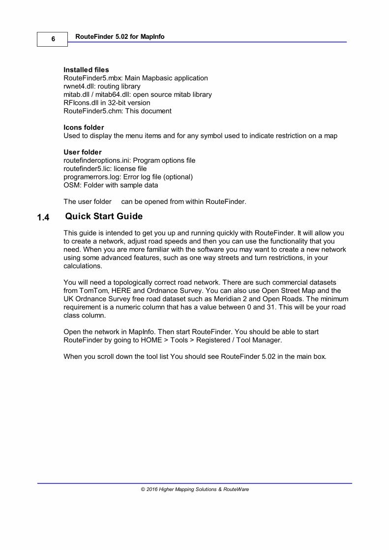
Installed filesRouteFinder5.mbx: Main Mapbasic applicationrwnet4.dll: routing librarymitab.dll / mitab64.dll: open source mitab libraryRFIcons.dll in 32-bit versionRouteFinder5.chm: This document
Icons folderUsed to display the menu items and for any symbol used to indicate restriction on a map
User folderroutefinderoptions.ini: Program options fileroutefinder5.lic: license fileprogramerrors.log: Error log file (optional)OSM: Folder with sample data
The user folder can be opened from within RouteFinder.
1.4 Quick Start Guide
This guide is intended to get you up and running quickly with RouteFinder. It will allow youto create a network, adjust road speeds and then you can use the functionality that youneed. When you are more familiar with the software you may want to create a new networkusing some advanced features, such as one way streets and turn restrictions, in yourcalculations.
You will need a topologically correct road network. There are such commercial datasetsfrom TomTom, HERE and Ordnance Survey. You can also use Open Street Map and theUK Ordnance Survey free road dataset such as Meridian 2 and Open Roads. The minimumrequirement is a numeric column that has a value between 0 and 31. This will be your roadclass column.
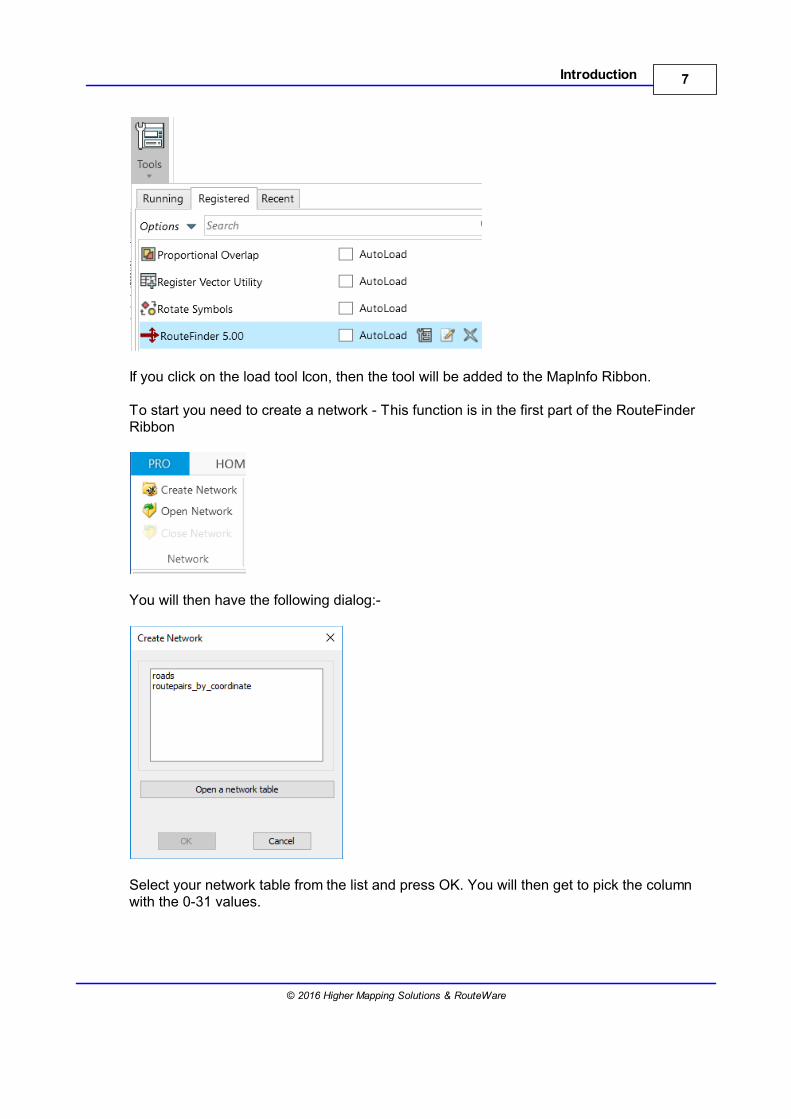
Open the network in MapInfo. Then start RouteFinder. You should be able to startRouteFinder by going to HOME > Tools > Registered / Tool Manager.
When you scroll down the tool list You should see RouteFinder 5.02 in the main box.
7Introduction
© 2016 Higher Mapping Solutions & RouteWare
If you click on the load tool Icon, then the tool will be added to the MapInfo Ribbon.
To start you need to create a network - This function is in the first part of the RouteFinderRibbon
You will then have the following dialog:-
Select your network table from the list and press OK. You will then get to pick the columnwith the 0-31 values.
8 RouteFinder 5.02 for MapInfo
© 2016 Higher Mapping Solutions & RouteWare
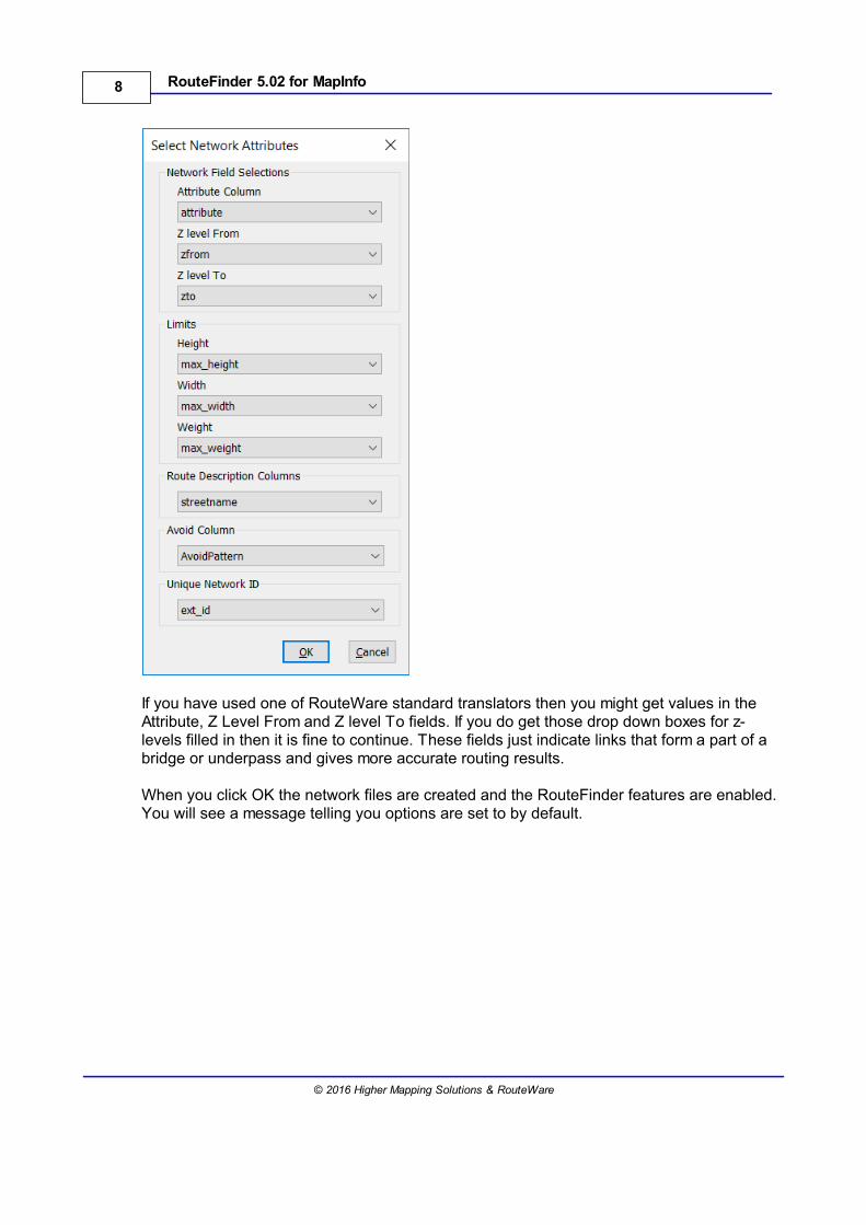
If you have used one of RouteWare standard translators then you might get values in theAttribute, Z Level From and Z level To fields. If you do get those drop down boxes for z-levels filled in then it is fine to continue. These fields just indicate links that form a part of abridge or underpass and gives more accurate routing results.
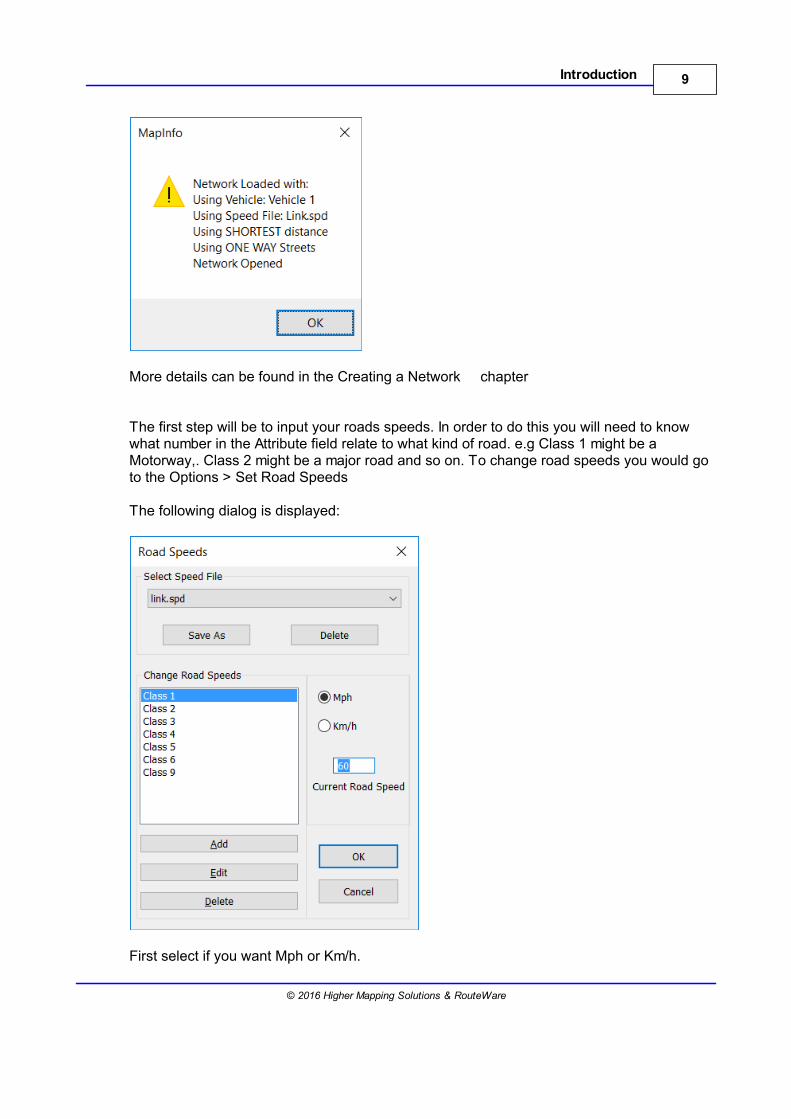
When you click OK the network files are created and the RouteFinder features are enabled.You will see a message telling you options are set to by default.
9Introduction
© 2016 Higher Mapping Solutions & RouteWare
More details can be found in the Creating a Network chapter
The first step will be to input your roads speeds. In order to do this you will need to knowwhat number in the Attribute field relate to what kind of road. e.g Class 1 might be aMotorway,. Class 2 might be a major road and so on. To change road speeds you would goto the Options > Set Road Speeds
The following dialog is displayed:
First select if you want Mph or Km/h.
10 RouteFinder 5.02 for MapInfo
© 2016 Higher Mapping Solutions & RouteWare
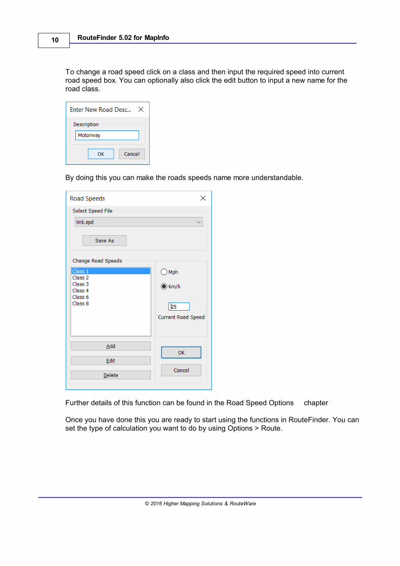
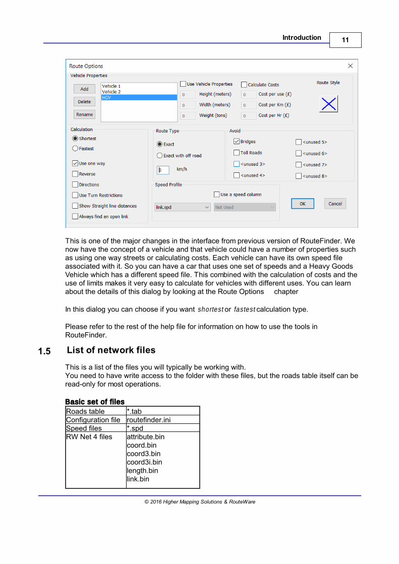
To change a road speed click on a class and then input the required speed into currentroad speed box. You can optionally also click the edit button to input a new name for theroad class.
By doing this you can make the roads speeds name more understandable.
Further details of this function can be found in the Road Speed Options chapter
Once you have done this you are ready to start using the functions in RouteFinder. You canset the type of calculation you want to do by using Options > Route.
11Introduction
© 2016 Higher Mapping Solutions & RouteWare
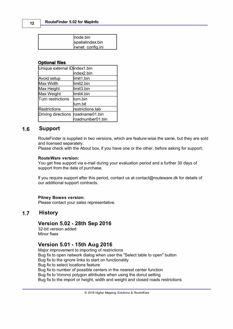
This is one of the major changes in the interface from previous version of RouteFinder. Wenow have the concept of a vehicle and that vehicle could have a number of properties suchas using one way streets or calculating costs. Each vehicle can have its own speed fileassociated with it. So you can have a car that uses one set of speeds and a Heavy GoodsVehicle which has a different speed file. This combined with the calculation of costs and theuse of limits makes it very easy to calculate for vehicles with different uses. You can learnabout the details of this dialog by looking at the Route Options chapter
In this dialog you can choose if you want shortest or fastest calculation type.
Please refer to the rest of the help file for information on how to use the tools inRouteFinder.
1.5 List of network files
This is a list of the files you will typically be working with.You need to have write access to the folder with these files, but the roads table itself can beread-only for most operations.
Basic set of files
Roads table *.tabConfiguration file routefinder.iniSpeed files *.spdRW Net 4 files attribute.bin
coord.bincoord3.bincoord3i.binlength.binlink.bin
12 RouteFinder 5.02 for MapInfo
© 2016 Higher Mapping Solutions & RouteWare
node.binspatialindex.binrwnet_config.ini
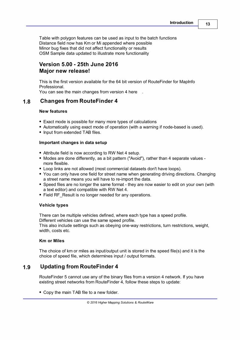
Optional files
Unique external IDindex1.binindex2.bin
Avoid setup limit1.binMax Width limit2.binMax Height limit3.binMax Weight limit4.binTurn restrictions turn.bin
turn.txtRestrictions restrictions.tabDriving directions roadname01.bin
roadnumber01.bin
1.6 Support
RouteFinder is supplied in two versions, which are feature-wise the same, but they are soldand licensed separately.Please check with the About box, if you have one or the other, before asking for support:
RouteWare version:You get free support via e-mail during your evaluation period and a further 30 days ofsupport from the date of purchase.
If you require support after this period, contact us at [email protected] for details ofour additional support contracts.
Pitney Bowes version:Please contact your sales representative.
1.7 History
Version 5.02 - 28th Sep 201632-bit version addedMinor fixes
Version 5.01 - 15th Aug 2016Major improvement to importing of restrictionsBug fix to open network dialog when user the "Select table to open" buttonBug fix to the ignore links to start on functionalityBug fix to select locations featureBug fix to number of possible centers in the nearest center functionBug fix to Voronoi polygon attributes when using the donut settingBug fix to the import or height, width and weight and closed roads restrictions
13Introduction
© 2016 Higher Mapping Solutions & RouteWare
Table with polygon features can be used as input to the batch functionsDistance field now has Km or Mi appended where possibleMinor bug fixes that did not affect functionality or resultsOSM Sample data updated to illustrate more functionality
Version 5.00 - 25th June 2016Major new release!
This is the first version available for the 64 bit version of RouteFinder for MapInfoProfessional.You can see the main changes from version 4 here .
1.8 Changes from RouteFinder 4
New features
Exact mode is possible for many more types of calculationsAutomatically using exact mode of operation (with a warning if node-based is used).Input from extended TAB files.
Important changes in data setup
Attribute field is now according to RW Net 4 setup.Modes are done differently, as a bit pattern ("Avoid"), rather than 4 separate values -more flexible.Loop links are not allowed (most commercial datasets don't have loops).You can only have one field for street name when generating driving directions. Changinga street name means you will have to re-import the data.Speed files are no longer the same format - they are now easier to edit on your own (witha text editor) and compatible with RW Net 4.Field RF_Result is no longer needed for any operations.
Vehicle types
There can be multiple vehicles defined, where each type has a speed profile.Different vehicles can use the same speed profile.This also include settings such as obeying one-way restrictions, turn restrictions, weight,width, costs etc.
Km or Miles
The choice of km or miles as input/output unit is stored in the speed file(s) and it is thechoice of speed file, which determines input / output formats.
1.9 Updating from RouteFinder 4
RouteFinder 5 cannot use any of the binary files from a version 4 network. If you haveexisting street networks from RouteFinder 4, follow these steps to update:
Copy the main TAB file to a new folder.
14 RouteFinder 5.02 for MapInfo
© 2016 Higher Mapping Solutions & RouteWare
If you have a turn.txt file, copy it to the same folder.Bit 5-6-7-8 (mode bits) in the attribute field should be cleared, if set ( that is if you haveadded 32, 64, 128, 256 to any attributes).
Now you are ready to create a network from the TAB file.
The rest of the files are not compatible with RouteFinder 5:
1) routefinder.ini2) *.spd files3) *.bin files4) restrictions.tab (if generated by RouteFinder)
1.10 License Agreement
RouteFinder 5 for MapInfo Professional© 2001-2016 by RouteWare and Higher Mapping SolutionsAll rights reserved
SOFTWARE LICENSEA single user license permits the use of RouteFinder on a single computer. Multiple userlicenses will be subject to the terms and conditions granted in such license.You may not translate, reverse engineer, decompile, disassemble, modify or patch theRouteFinder executable files or documentation in any way.You may not use the RW Net 4 DLL outside of RouteFinder in any way.
LIMITED WARRANTYRouteWare warrants that all disks provided are free from defects in material andworkmanship, assuming normal use, for a period of 90 days from the date of purchase.
RouteWare warrants that the program will perform in substantial compliance with thedocumentation supplied with the software product. If a significant defect in the product isfound, the Purchaser may return the product for a refund. In no event will such a refundexceed the purchase price of the product.
EXCEPT AS PROVIDED ABOVE, ROUTEWARE DISCLAIMS ALL WARRANTIES, EITHEREXPRESS OR IMPLIED, INCLUDING, BUT NOT LIMITED TO IMPLIED WARRANTIES OFMERCHANTABILITY AND FITNESS FOR A PARTICULAR PURPOSE, WITH RESPECTTO THE PRODUCT. SHOULD THE PROGRAM PROVE DEFECTIVE, THE PURCHASERASSUMES THE RISK OF PAYING THE ENTIRE COST OF ALL NECESSARYSERVICING, REPAIR, OR CORRECTION AND ANY INCIDENTAL OR CONSEQUENTIALDAMAGES. IN NO EVENT WILL ROUTEWARE BE LIABLE FOR ANY DAMAGESWHATSOEVER (INCLUDING WITHOUT LIMITATION DAMAGES FOR LOSS OFBUSINESS PROFITS, BUSINESS INTERRUPTION, LOSS OF BUSINESS INFORMATIONAND THE LIKE) ARISING OUT OF THE USE OR THE INABILITY TO USE THISPRODUCT EVEN IF ROUTEWARE HAS BEEN ADVISED OF THE POSSIBILITY OFSUCH DAMAGES.
Use of this product for any period of time constitutes your acceptance of this agreementand subjects you to its contents.
15Introduction
© 2016 Higher Mapping Solutions & RouteWare
1.11 SDK
RouteFinder is built on top of RW Net 4, which is available as a separate SDK (softwaredevelopment kit).
Please see the RouteWare website for details about RW Net 4.
1.12 Acknowledgements
Thanks to Peter Møller for use of his RibbonLib for menu building in 64-bit MapInfo.
Thanks to the community around MITAB and GDAL / OGR for the mitab library for writingTAB files.
Thanks to OpenStreetMap for providing what is the basis of our sample data.However, our version is heavily modified to illustrate elements of RouteFinder.


Basic Functions
Part II

19Basic Functions
© 2016 Higher Mapping Solutions & RouteWare
2 Basic Functions
This section explains how to create a network from a MapInfo Table and how to set theoptions that affect how routes or isochrones are calculated.
You can also set various options for some program wide settings.
2.1 Creating a Network
Go to Create Network
In order to create a network to use for routing with RouteFinder, these steps should havebeen prepared first:
Input fileYou need to have a TAB file in either native format or native extended format. It shouldcontain lines and polylines only.
Road class attributeThis field will define the different classes of roads. The basic classes of road should bebetween 0 and 31. To define a one way street add 512. Add 1024 to create a one-waystreet that has been digitised in the wrong direction.
Each road class from 0 to 31 can be assigned a different speed through the Road Speedoptions after the network has been created and loaded.
An example: If the first link in the network is a class 1 road (e.g. a motorway), which canonly be travelled in the direction of digitizing, the attribute will be 1 + 512 = 513.
There are more settings you can add manually to a link and they are:
Add 512 if it is a one-way street, which may be travelled in the digitised direction. Add 1024 if it is a one-way street, which may be travelled in the opposite to the digitiseddirection. Add 2048 if a link is part of a roundabout. This is used in generating driving directions. Add 4096 if a link is a "non-driving" link. This can be used to mark ferries and car trains, sotheir length is not included in driving directions. Add 8192 if it is not allowed to make U-turns at the from-end of the link.Add 16384 if it is not allowed to make U-turns at the to-end of the link.Add 32768 if it is not allowed for a route to start on the link.
If you don't have any information about road classes, just add an integer field with all zero's.This means the same speed is used all over the network and all links can be travelled inboth directions.
Actual creation of network
20 RouteFinder 5.02 for MapInfo
© 2016 Higher Mapping Solutions & RouteWare
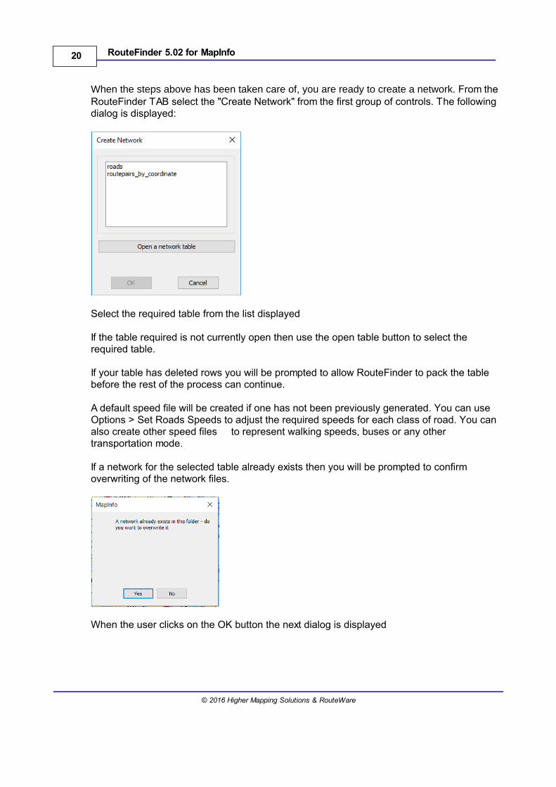
When the steps above has been taken care of, you are ready to create a network. From theRouteFinder TAB select the "Create Network" from the first group of controls. The followingdialog is displayed:
Select the required table from the list displayed
If the table required is not currently open then use the open table button to select therequired table.
If your table has deleted rows you will be prompted to allow RouteFinder to pack the tablebefore the rest of the process can continue.
A default speed file will be created if one has not been previously generated. You can useOptions > Set Roads Speeds to adjust the required speeds for each class of road. You canalso create other speed files to represent walking speeds, buses or any othertransportation mode.
If a network for the selected table already exists then you will be prompted to confirmoverwriting of the network files.
When the user clicks on the OK button the next dialog is displayed
21Basic Functions
© 2016 Higher Mapping Solutions & RouteWare
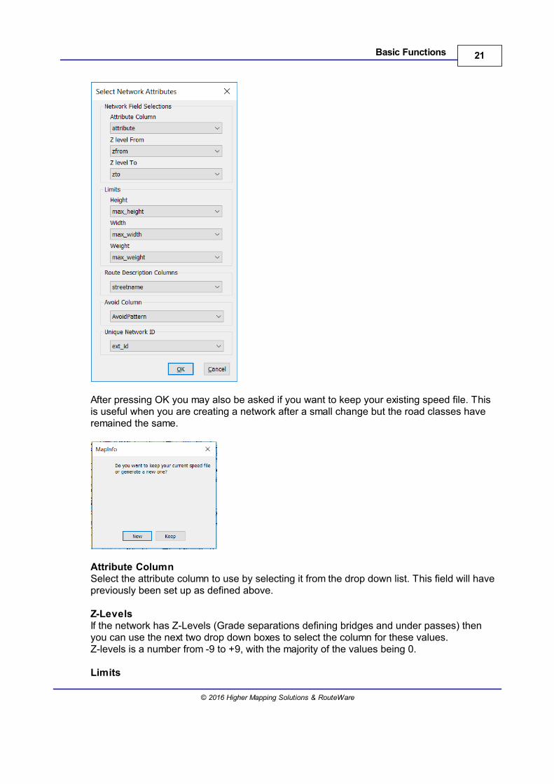
After pressing OK you may also be asked if you want to keep your existing speed file. Thisis useful when you are creating a network after a small change but the road classes haveremained the same.
Attribute ColumnSelect the attribute column to use by selecting it from the drop down list. This field will havepreviously been set up as defined above.
Z-LevelsIf the network has Z-Levels (Grade separations defining bridges and under passes) thenyou can use the next two drop down boxes to select the column for these values.Z-levels is a number from -9 to +9, with the majority of the values being 0.
Limits
22 RouteFinder 5.02 for MapInfo
© 2016 Higher Mapping Solutions & RouteWare
It is possible to define height, width and weight restrictions and these are store in a smallintcolumn (range 0-255) in the table and affect the link associated with that row.
Height restrictions are defined in tenths of a meter in 0.1 steps (i.e 73 = 7.3 meters)Width restrictions are defined in tenths of a meter in 0.1 steps (i.e 52 = 5.2 meters)Weight restriction are define in half a tonne steps (i.e 19 = 9.5 tonnes)
These values are stores in their own columns and more than one restriction can be definedon each link.
Route Description ColumnThe route descriptions are set from the column containing the relevant data and is selectedfrom the drop down list. When a route or traveling salesman has been generated a windowwill appear with the directions and it will also be possible to click on each part of the routedescription and see it highlighted on the map.
Avoid ColumnThis column will hold details of situation when this link should be avoided. It might be thatthe link is not safe to walk on or you may want to avoid toll-roads. Up to 8 avoids can bedefined on a single link.
In order to define avoids you would add the following values to Avoid column in your table
1 - Avoid setting 12 - Avoid setting 24 - Avoid setting 38 - Avoid setting 416 - Avoid setting 532 - Avoid setting 664 - Avoid setting 7128 - Avoid setting 8
The avoid values are additive so if you wanted a specific link to be avoided in option 1, 2, 5and 6 then the value in the avoid column in your table would be:-
1 + 2 + 16 + 32 = 51
23Basic Functions
© 2016 Higher Mapping Solutions & RouteWare
You can manage these settings via the Set Avoids option in the restrictions group.
Unique Network ID ColumnThis column would contain a unique reference for a link in the database. It would be usedwhen you want to import turn restrictions that are based on a Link ID rather than a row id.When picking a field, it is not checked if it is actually unique. If it isn't, you may get somestrange results when importing turn restriction files.
The network is loaded and the controls are enabled for use.
2.2 Road Speed Options
Go to Options > Road Speeds
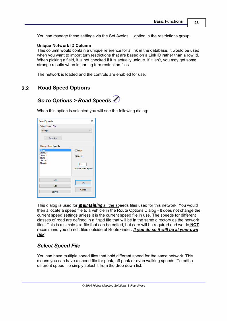
When this option is selected you will see the following dialog:
This dialog is used for m a in ta in in g all the speeds files used for this network. You wouldthen allocate a speed file to a vehicle in the Route Options Dialog - It does not change thecurrent speed settings unless it is the current speed file in use. The speeds for differentclasses of road are defined in a *.spd file that will be in the same directory as the networkfiles. This is a simple text file that can be edited, but care will be required and we do NOTrecommend you do edit files outside of RouteFinder. If you do so it will be at your ownrisk.
Select Speed File
You can have multiple speed files that hold different speed for the same network. Thismeans you can have a speed file for peak, off peak or even walking speeds. To edit adifferent speed file simply select it from the drop down list.
24 RouteFinder 5.02 for MapInfo
© 2016 Higher Mapping Solutions & RouteWare
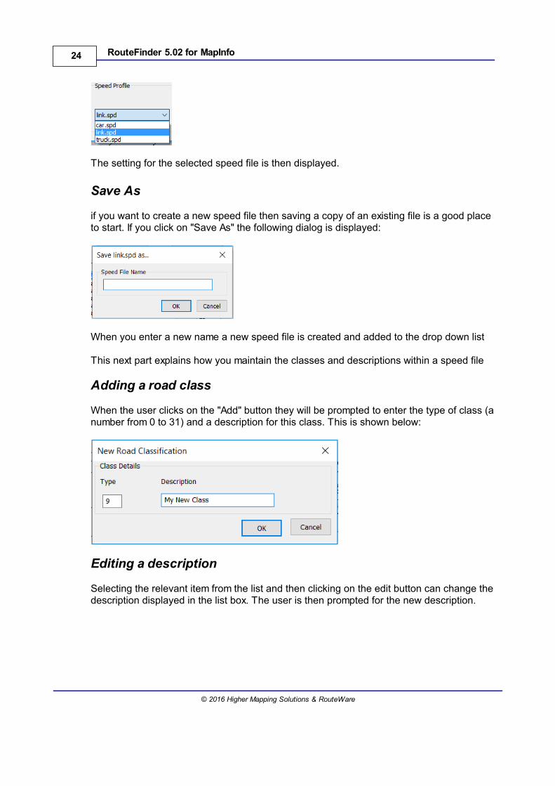
The setting for the selected speed file is then displayed.
Save As
if you want to create a new speed file then saving a copy of an existing file is a good placeto start. If you click on "Save As" the following dialog is displayed:
When you enter a new name a new speed file is created and added to the drop down list
This next part explains how you maintain the classes and descriptions within a speed file
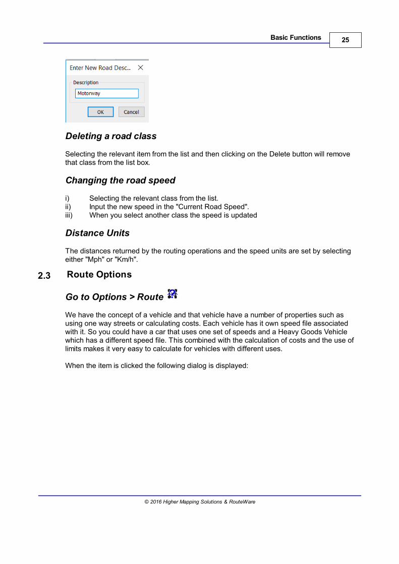
Adding a road class
When the user clicks on the "Add" button they will be prompted to enter the type of class (anumber from 0 to 31) and a description for this class. This is shown below:
Editing a description
Selecting the relevant item from the list and then clicking on the edit button can change thedescription displayed in the list box. The user is then prompted for the new description.
25Basic Functions
© 2016 Higher Mapping Solutions & RouteWare
Deleting a road class
Selecting the relevant item from the list and then clicking on the Delete button will removethat class from the list box.
Changing the road speed
i) Selecting the relevant class from the list.ii) Input the new speed in the "Current Road Speed".iii) When you select another class the speed is updated
Distance Units
The distances returned by the routing operations and the speed units are set by selectingeither "Mph" or "Km/h".
2.3 Route Options
Go to Options > Route
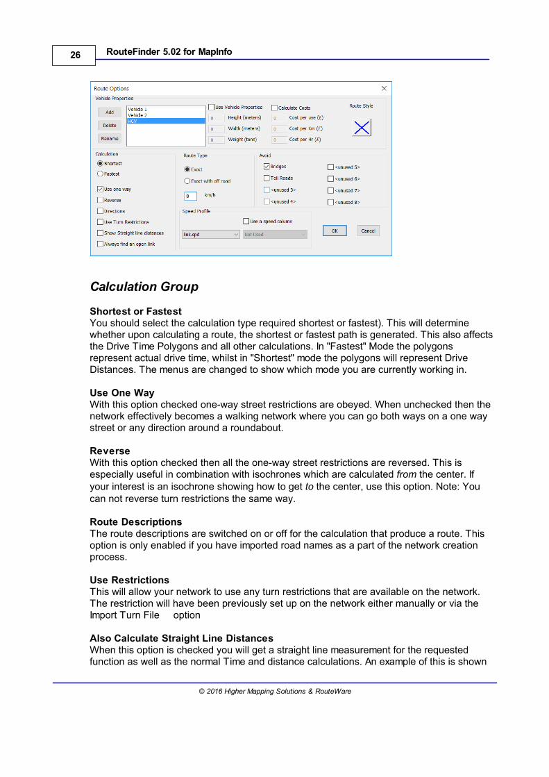
We have the concept of a vehicle and that vehicle have a number of properties such asusing one way streets or calculating costs. Each vehicle has it own speed file associatedwith it. So you could have a car that uses one set of speeds and a Heavy Goods Vehiclewhich has a different speed file. This combined with the calculation of costs and the use oflimits makes it very easy to calculate for vehicles with different uses.
When the item is clicked the following dialog is displayed:
26 RouteFinder 5.02 for MapInfo
© 2016 Higher Mapping Solutions & RouteWare
Calculation Group
Shortest or FastestYou should select the calculation type required shortest or fastest). This will determinewhether upon calculating a route, the shortest or fastest path is generated. This also affectsthe Drive Time Polygons and all other calculations. In "Fastest" Mode the polygonsrepresent actual drive time, whilst in "Shortest" mode the polygons will represent DriveDistances. The menus are changed to show which mode you are currently working in.
Use One WayWith this option checked one-way street restrictions are obeyed. When unchecked then thenetwork effectively becomes a walking network where you can go both ways on a one waystreet or any direction around a roundabout.
ReverseWith this option checked then all the one-way street restrictions are reversed. This isespecially useful in combination with isochrones which are calculated from the center. Ifyour interest is an isochrone showing how to get to the center, use this option. Note: Youcan not reverse turn restrictions the same way.
Route DescriptionsThe route descriptions are switched on or off for the calculation that produce a route. Thisoption is only enabled if you have imported road names as a part of the network creationprocess.
Use RestrictionsThis will allow your network to use any turn restrictions that are available on the network.The restriction will have been previously set up on the network either manually or via the Import Turn File option
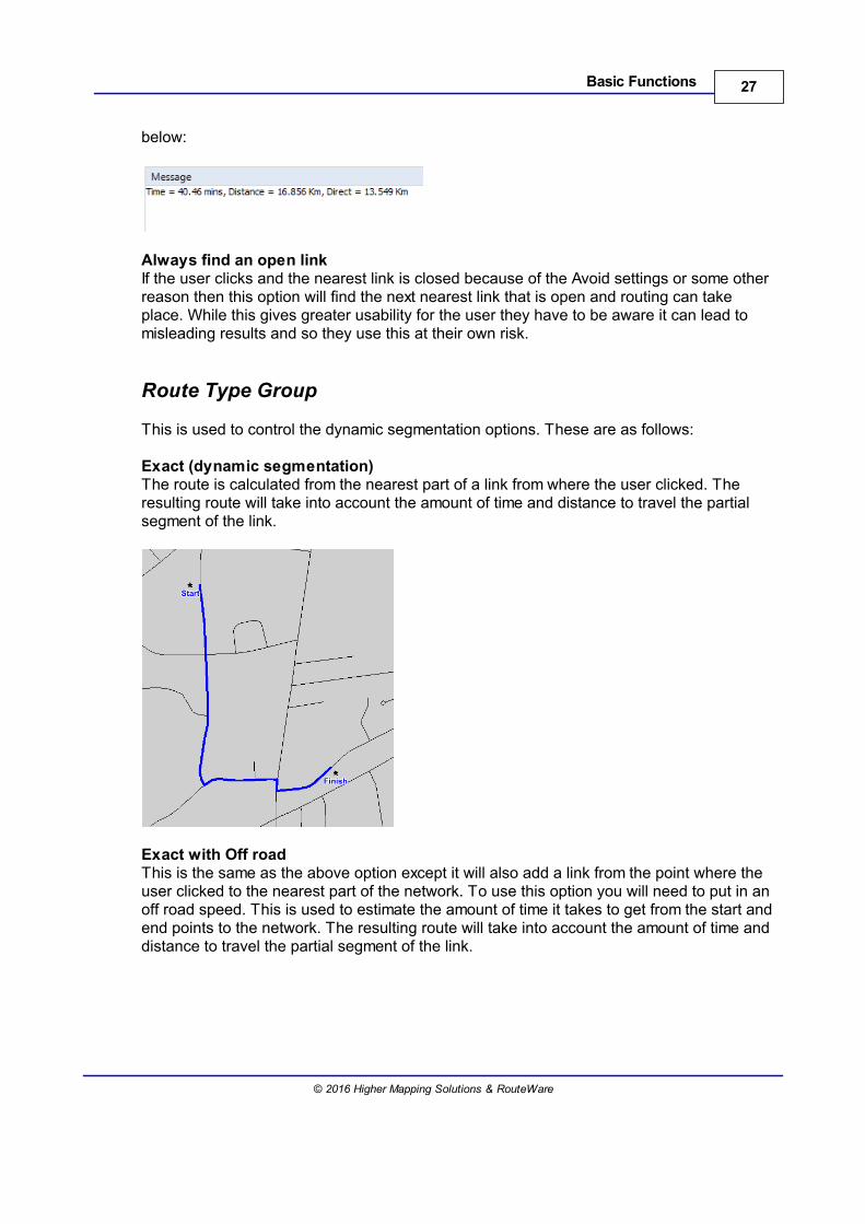
Also Calculate Straight Line DistancesWhen this option is checked you will get a straight line measurement for the requestedfunction as well as the normal Time and distance calculations. An example of this is shown
27Basic Functions
© 2016 Higher Mapping Solutions & RouteWare
below:
Always find an open linkIf the user clicks and the nearest link is closed because of the Avoid settings or some otherreason then this option will find the next nearest link that is open and routing can takeplace. While this gives greater usability for the user they have to be aware it can lead tomisleading results and so they use this at their own risk.
Route Type Group
This is used to control the dynamic segmentation options. These are as follows:
Exact (dynamic segmentation)The route is calculated from the nearest part of a link from where the user clicked. Theresulting route will take into account the amount of time and distance to travel the partialsegment of the link.
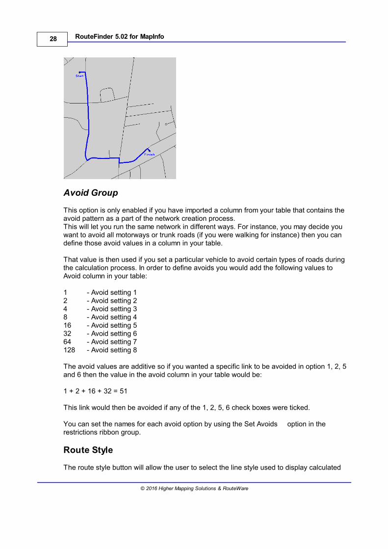
Exact with Off road This is the same as the above option except it will also add a link from the point where theuser clicked to the nearest part of the network. To use this option you will need to put in anoff road speed. This is used to estimate the amount of time it takes to get from the start andend points to the network. The resulting route will take into account the amount of time anddistance to travel the partial segment of the link.
28 RouteFinder 5.02 for MapInfo
© 2016 Higher Mapping Solutions & RouteWare
Avoid Group
This option is only enabled if you have imported a column from your table that contains theavoid pattern as a part of the network creation process.This will let you run the same network in different ways. For instance, you may decide youwant to avoid all motorways or trunk roads (if you were walking for instance) then you candefine those avoid values in a column in your table.
That value is then used if you set a particular vehicle to avoid certain types of roads duringthe calculation process. In order to define avoids you would add the following values toAvoid column in your table:
1 - Avoid setting 12 - Avoid setting 24 - Avoid setting 38 - Avoid setting 416 - Avoid setting 532 - Avoid setting 664 - Avoid setting 7128 - Avoid setting 8
The avoid values are additive so if you wanted a specific link to be avoided in option 1, 2, 5and 6 then the value in the avoid column in your table would be:
1 + 2 + 16 + 32 = 51
This link would then be avoided if any of the 1, 2, 5, 6 check boxes were ticked.
You can set the names for each avoid option by using the Set Avoids option in therestrictions ribbon group.
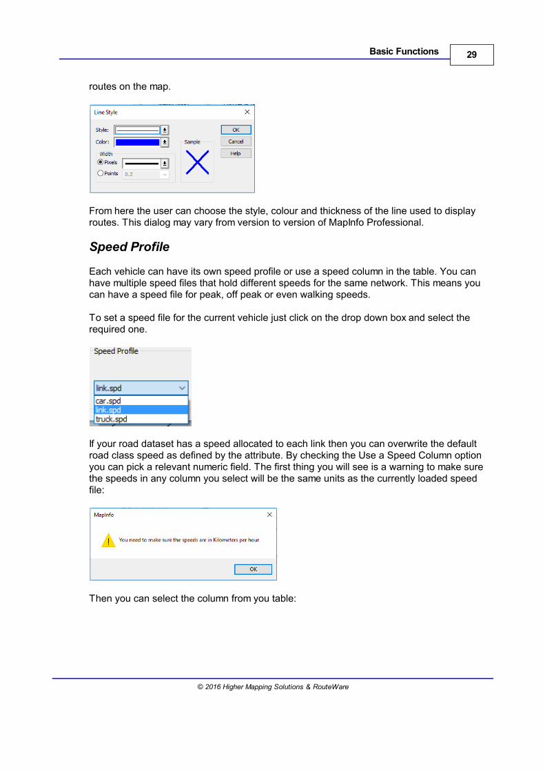
Route Style
The route style button will allow the user to select the line style used to display calculated
29Basic Functions
© 2016 Higher Mapping Solutions & RouteWare
routes on the map.
From here the user can choose the style, colour and thickness of the line used to displayroutes. This dialog may vary from version to version of MapInfo Professional.
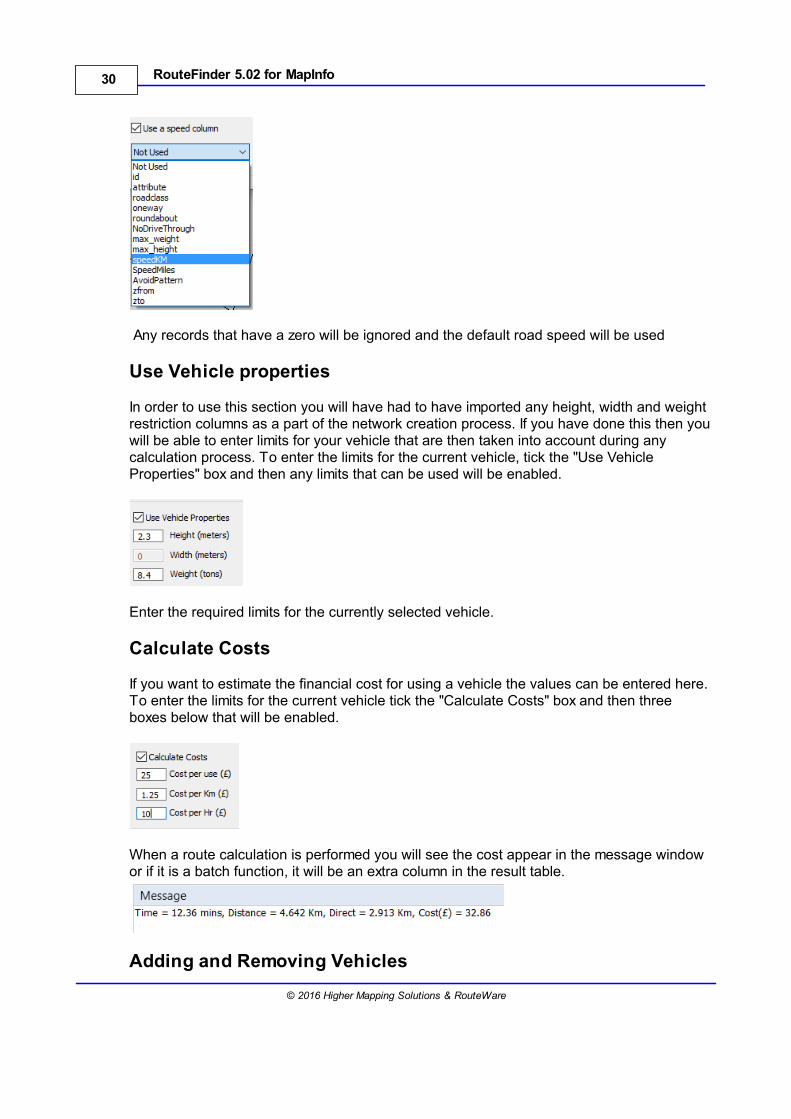
Speed Profile
Each vehicle can have its own speed profile or use a speed column in the table. You canhave multiple speed files that hold different speeds for the same network. This means youcan have a speed file for peak, off peak or even walking speeds.
To set a speed file for the current vehicle just click on the drop down box and select therequired one.
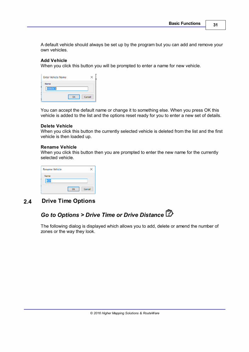
If your road dataset has a speed allocated to each link then you can overwrite the defaultroad class speed as defined by the attribute. By checking the Use a Speed Column optionyou can pick a relevant numeric field. The first thing you will see is a warning to make surethe speeds in any column you select will be the same units as the currently loaded speedfile:
Then you can select the column from you table:
30 RouteFinder 5.02 for MapInfo
© 2016 Higher Mapping Solutions & RouteWare
Any records that have a zero will be ignored and the default road speed will be used
Use Vehicle properties
In order to use this section you will have had to have imported any height, width and weightrestriction columns as a part of the network creation process. If you have done this then youwill be able to enter limits for your vehicle that are then taken into account during anycalculation process. To enter the limits for the current vehicle, tick the "Use VehicleProperties" box and then any limits that can be used will be enabled.
Enter the required limits for the currently selected vehicle.
Calculate Costs
If you want to estimate the financial cost for using a vehicle the values can be entered here.To enter the limits for the current vehicle tick the "Calculate Costs" box and then threeboxes below that will be enabled.
When a route calculation is performed you will see the cost appear in the message windowor if it is a batch function, it will be an extra column in the result table.
Adding and Removing Vehicles
31Basic Functions
© 2016 Higher Mapping Solutions & RouteWare
A default vehicle should always be set up by the program but you can add and remove yourown vehicles.
Add VehicleWhen you click this button you will be prompted to enter a name for new vehicle.
You can accept the default name or change it to something else. When you press OK thisvehicle is added to the list and the options reset ready for you to enter a new set of details.
Delete VehicleWhen you click this button the currently selected vehicle is deleted from the list and the firstvehicle is then loaded up.
Rename VehicleWhen you click this button then you are prompted to enter the new name for the currentlyselected vehicle.
2.4 Drive Time Options
Go to Options > Drive Time or Drive Distance
The following dialog is displayed which allows you to add, delete or amend the number ofzones or the way they look.
32 RouteFinder 5.02 for MapInfo
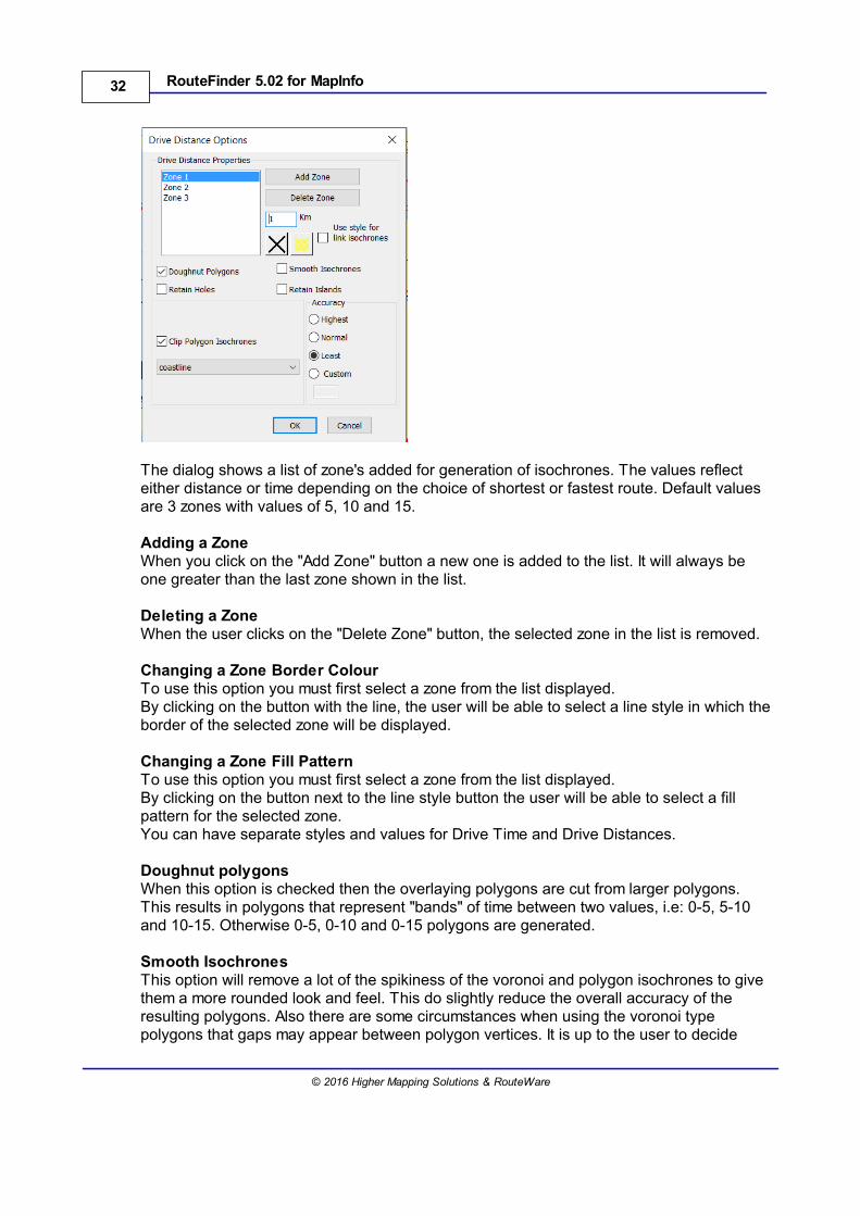
© 2016 Higher Mapping Solutions & RouteWare
The dialog shows a list of zone's added for generation of isochrones. The values reflecteither distance or time depending on the choice of shortest or fastest route. Default valuesare 3 zones with values of 5, 10 and 15.
Adding a ZoneWhen you click on the "Add Zone" button a new one is added to the list. It will always beone greater than the last zone shown in the list.
Deleting a ZoneWhen the user clicks on the "Delete Zone" button, the selected zone in the list is removed.
Changing a Zone Border ColourTo use this option you must first select a zone from the list displayed.By clicking on the button with the line, the user will be able to select a line style in which theborder of the selected zone will be displayed.
Changing a Zone Fill PatternTo use this option you must first select a zone from the list displayed. By clicking on the button next to the line style button the user will be able to select a fillpattern for the selected zone.You can have separate styles and values for Drive Time and Drive Distances.
Doughnut polygonsWhen this option is checked then the overlaying polygons are cut from larger polygons.This results in polygons that represent "bands" of time between two values, i.e: 0-5, 5-10and 10-15. Otherwise 0-5, 0-10 and 0-15 polygons are generated.
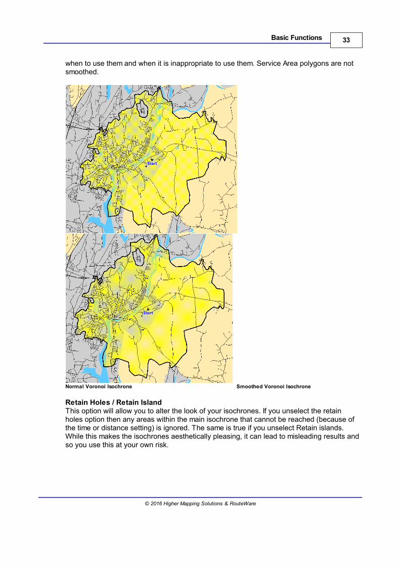
Smooth IsochronesThis option will remove a lot of the spikiness of the voronoi and polygon isochrones to givethem a more rounded look and feel. This do slightly reduce the overall accuracy of theresulting polygons. Also there are some circumstances when using the voronoi typepolygons that gaps may appear between polygon vertices. It is up to the user to decide
33Basic Functions
© 2016 Higher Mapping Solutions & RouteWare
when to use them and when it is inappropriate to use them. Service Area polygons are notsmoothed.
Normal Voronoi Isochrone Smoothed Voronoi Isochrone
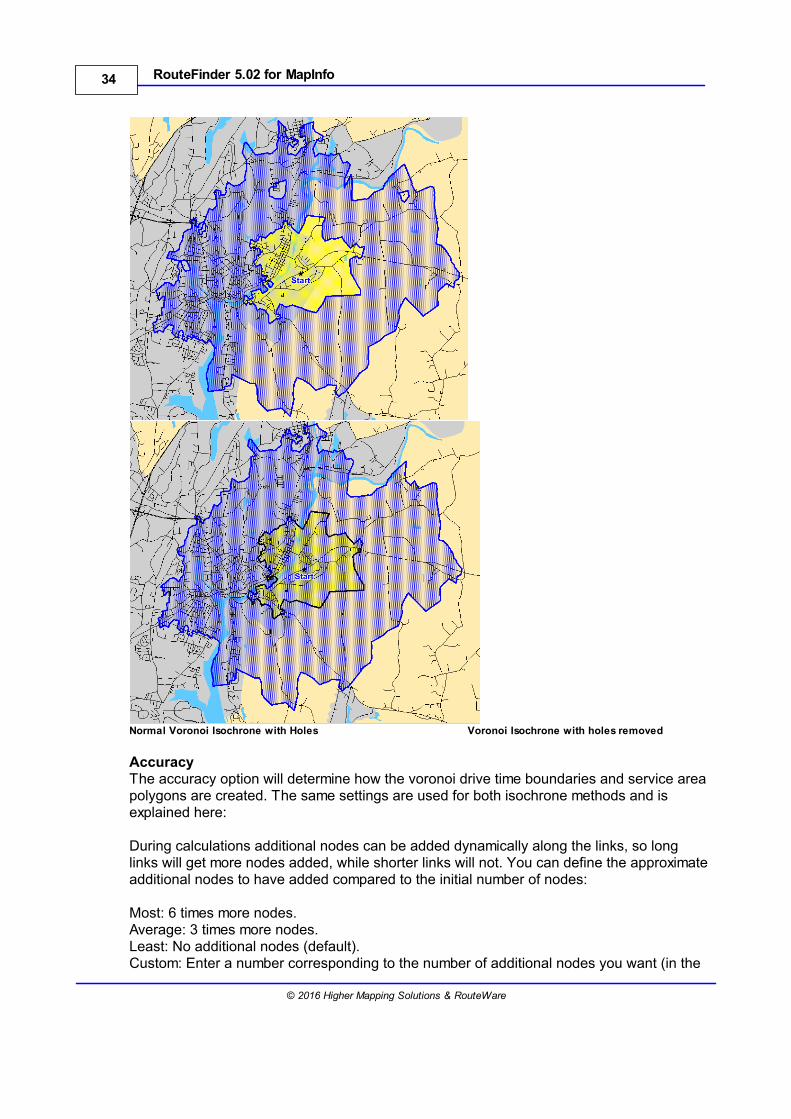
Retain Holes / Retain IslandThis option will allow you to alter the look of your isochrones. If you unselect the retainholes option then any areas within the main isochrone that cannot be reached (because ofthe time or distance setting) is ignored. The same is true if you unselect Retain islands.While this makes the isochrones aesthetically pleasing, it can lead to misleading results andso you use this at your own risk.
34 RouteFinder 5.02 for MapInfo
© 2016 Higher Mapping Solutions & RouteWare
Normal Voronoi Isochrone with Holes Voronoi Isochrone with holes removed
AccuracyThe accuracy option will determine how the voronoi drive time boundaries and service areapolygons are created. The same settings are used for both isochrone methods and isexplained here:
During calculations additional nodes can be added dynamically along the links, so longlinks will get more nodes added, while shorter links will not. You can define the approximateadditional nodes to have added compared to the initial number of nodes:
Most: 6 times more nodes.Average: 3 times more nodes.Least: No additional nodes (default).Custom: Enter a number corresponding to the number of additional nodes you want (in the
35Basic Functions
© 2016 Higher Mapping Solutions & RouteWare
same way as above).
The larger the number, the more RAM is needed and the requirements increases fast, sodon't just type in a very big number.
Most – The isochrone will reflect very accurately the extents of the boundaries using everylink in the network. This results in very jagged looking boundaries.Average – This will generalize some of the spikes to produce a smoother looking polygon.Least - This will generalize some of the spikes to produce a much smoother lookingpolygon.Custom - This is automatically set to be the most accurate isochrones possible. Theadditional nodes do not affect this function in any other way.
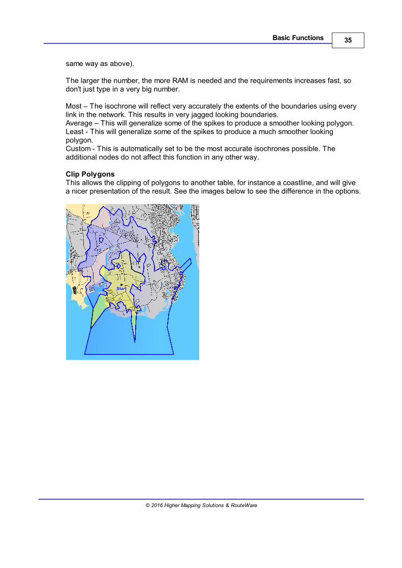
Clip PolygonsThis allows the clipping of polygons to another table, for instance a coastline, and will givea nicer presentation of the result. See the images below to see the difference in the options.
36 RouteFinder 5.02 for MapInfo
© 2016 Higher Mapping Solutions & RouteWare
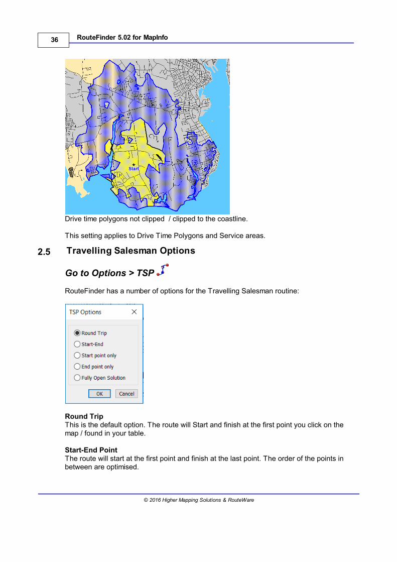
Drive time polygons not clipped / clipped to the coastline.
This setting applies to Drive Time Polygons and Service areas.
2.5 Travelling Salesman Options
Go to Options > TSP
RouteFinder has a number of options for the Travelling Salesman routine:
Round Trip This is the default option. The route will Start and finish at the first point you click on themap / found in your table.
Start-End Point The route will start at the first point and finish at the last point. The order of the points inbetween are optimised.
37Basic Functions
© 2016 Higher Mapping Solutions & RouteWare
Start-Point onlyThe Route will start at the first point and the order of the rest of the points are optimised.You will typically end at a point far away from the start point with this option (but notalways).
End Point OnlyThe Route will end at the last point and the order of the rest of the points are optimised.You will typically start at a point far away from the end point with this option (but notalways).
Fully Open SolutionThis will start and end at any location that has been entered.
2.6 Program Options
Go to Options > Program
This will set defaults for the way the program will work. It will then use the same settings nomatter what network is loaded. When clicked you will see the following dialog.
38 RouteFinder 5.02 for MapInfo
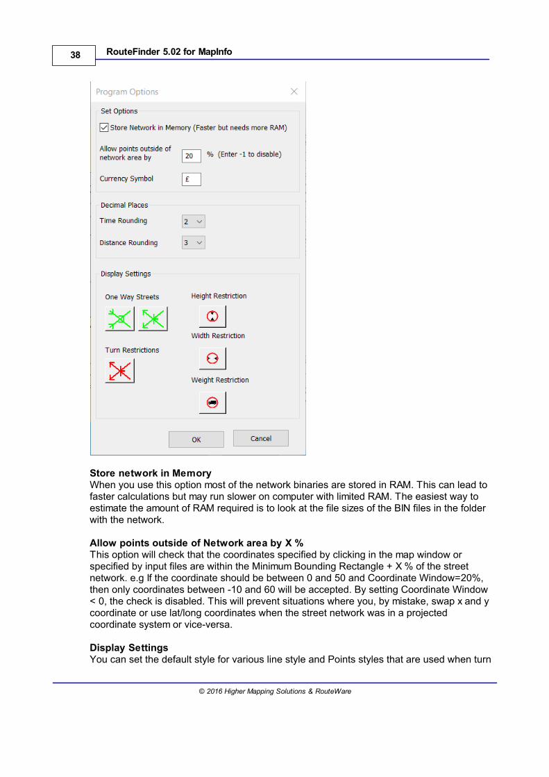
© 2016 Higher Mapping Solutions & RouteWare
Store network in MemoryWhen you use this option most of the network binaries are stored in RAM. This can lead tofaster calculations but may run slower on computer with limited RAM. The easiest way toestimate the amount of RAM required is to look at the file sizes of the BIN files in the folderwith the network.
Allow points outside of Network area by X %This option will check that the coordinates specified by clicking in the map window orspecified by input files are within the Minimum Bounding Rectangle + X % of the streetnetwork. e.g If the coordinate should be between 0 and 50 and Coordinate Window=20%,then only coordinates between -10 and 60 will be accepted. By setting Coordinate Window< 0, the check is disabled. This will prevent situations where you, by mistake, swap x and ycoordinate or use lat/long coordinates when the street network was in a projectedcoordinate system or vice-versa.
Display SettingsYou can set the default style for various line style and Points styles that are used when turn
39Basic Functions
© 2016 Higher Mapping Solutions & RouteWare
restrictions are used. These should be set before importing or adding restrictions to yournetwork.
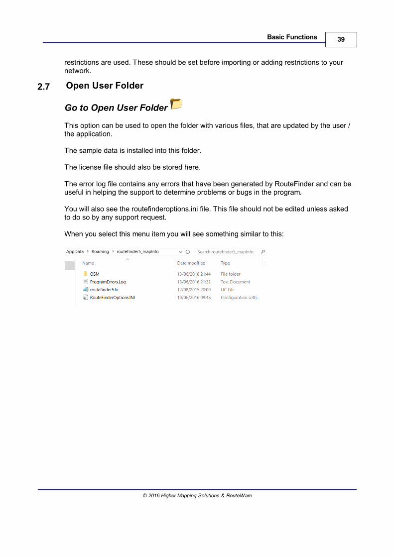
2.7 Open User Folder
Go to Open User Folder
This option can be used to open the folder with various files, that are updated by the user /the application.
The sample data is installed into this folder.
The license file should also be stored here.
The error log file contains any errors that have been generated by RouteFinder and can beuseful in helping the support to determine problems or bugs in the program.
You will also see the routefinderoptions.ini file. This file should not be edited unless askedto do so by any support request.
When you select this menu item you will see something similar to this:

Interactive Tools
Part III

43Interactive Tools
© 2016 Higher Mapping Solutions & RouteWare
3 Interactive Tools
The tools in this section are used by clicking in a map window when the network has beenloaded.
Routes can be generated with:Route - can have driving directionsTravelling Salesman - can have driving directions
Single or Multiple Isochrones can be generated with:Link IsochroneSimple IsochroneVoronoi IsochroneService Area
Various other functions:Update Point FileTraffic Volume
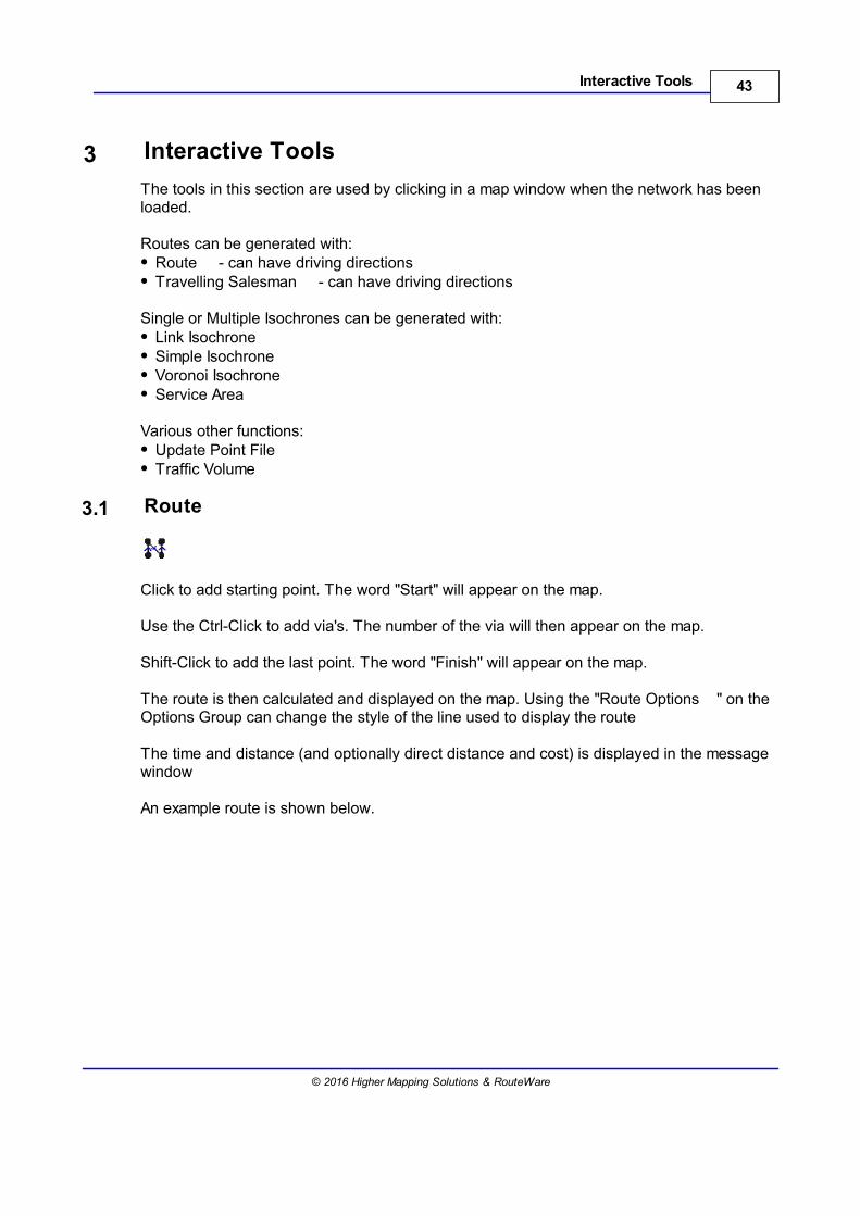
3.1 Route
Click to add starting point. The word "Start" will appear on the map.
Use the Ctrl-Click to add via's. The number of the via will then appear on the map.
Shift-Click to add the last point. The word "Finish" will appear on the map. The route is then calculated and displayed on the map. Using the "Route Options " on theOptions Group can change the style of the line used to display the route
The time and distance (and optionally direct distance and cost) is displayed in the messagewindow
An example route is shown below.
44 RouteFinder 5.02 for MapInfo
© 2016 Higher Mapping Solutions & RouteWare
To create routes based on points already recorded in a table, refer to either SelectLocations or other batch functions.
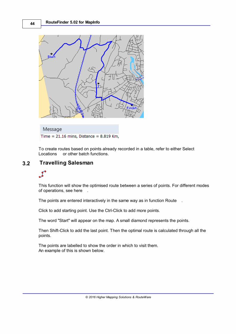
3.2 Travelling Salesman
This function will show the optimised route between a series of points. For different modesof operations, see here .
The points are entered interactively in the same way as in function Route .
Click to add starting point. Use the Ctrl-Click to add more points.
The word "Start" will appear on the map. A small diamond represents the points.
Then Shift-Click to add the last point. Then the optimal route is calculated through all thepoints.
The points are labelled to show the order in which to visit them.An example of this is shown below.
45Interactive Tools
© 2016 Higher Mapping Solutions & RouteWare
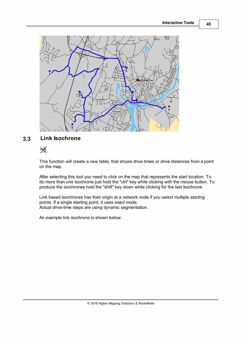
3.3 Link Isochrone
This function will create a new table, that shows drive times or drive distances from a pointon the map.
After selecting this tool you need to click on the map that represents the start location. Todo more than one isochrone just hold the "ctrl" key while clicking with the mouse button. Toproduce the isochrones hold the "shift" key down while clicking for the last Isochrone.
Link based isochrones has their origin at a network node if you select multiple startingpoints. If a single starting point, it uses exact mode.Actual drive-time steps are using dynamic segmentation.
An example link isochrone is shown below:
46 RouteFinder 5.02 for MapInfo
© 2016 Higher Mapping Solutions & RouteWare
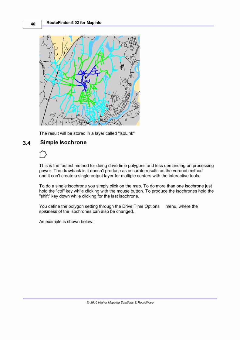
The result will be stored in a layer called "IsoLink"
3.4 Simple Isochrone
This is the fastest method for doing drive time polygons and less demanding on processingpower. The drawback is it doesn't produce as accurate results as the voronoi methodand it can't create a single output layer for multiple centers with the interactive tools.
To do a single isochrone you simply click on the map. To do more than one isochrone justhold the "ctrl" key while clicking with the mouse button. To produce the isochrones hold the"shift" key down while clicking for the last isochrone.
You define the polygon setting through the Drive Time Options menu, where thespikiness of the isochrones can also be changed.
An example is shown below:
47Interactive Tools
© 2016 Higher Mapping Solutions & RouteWare
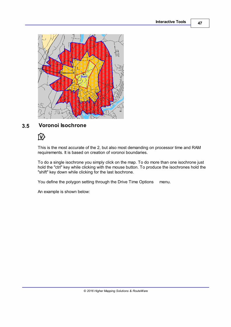
3.5 Voronoi Isochrone
This is the most accurate of the 2, but also most demanding on processor time and RAMrequirements. It is based on creation of voronoi boundaries.
To do a single isochrone you simply click on the map. To do more than one isochrone justhold the "ctrl" key while clicking with the mouse button. To produce the isochrones hold the"shift" key down while clicking for the last Isochrone.
You define the polygon setting through the Drive Time Options menu.
An example is shown below:
48 RouteFinder 5.02 for MapInfo
© 2016 Higher Mapping Solutions & RouteWare
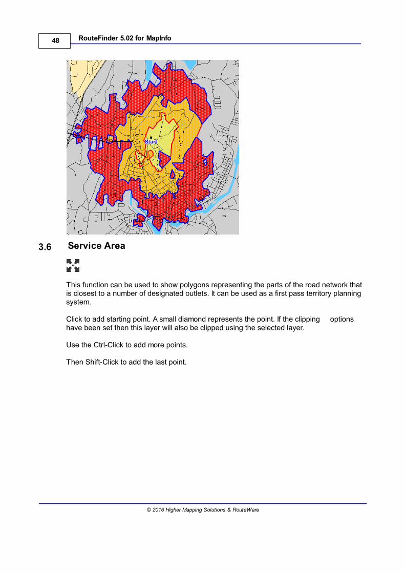
3.6 Service Area
This function can be used to show polygons representing the parts of the road network thatis closest to a number of designated outlets. It can be used as a first pass territory planningsystem.
Click to add starting point. A small diamond represents the point. If the clipping optionshave been set then this layer will also be clipped using the selected layer.
Use the Ctrl-Click to add more points.
Then Shift-Click to add the last point.
49Interactive Tools
© 2016 Higher Mapping Solutions & RouteWare
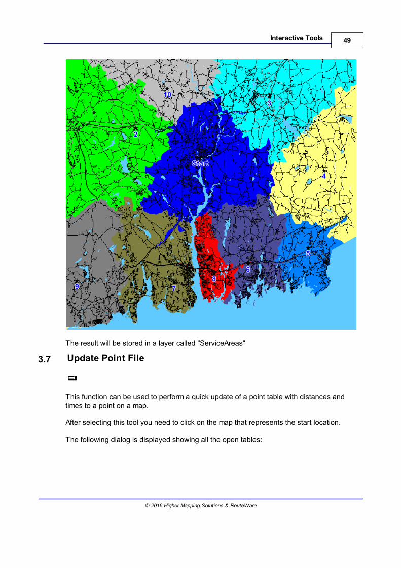
The result will be stored in a layer called "ServiceAreas"
3.7 Update Point File
This function can be used to perform a quick update of a point table with distances andtimes to a point on a map.
After selecting this tool you need to click on the map that represents the start location.
The following dialog is displayed showing all the open tables:
50 RouteFinder 5.02 for MapInfo
© 2016 Higher Mapping Solutions & RouteWare
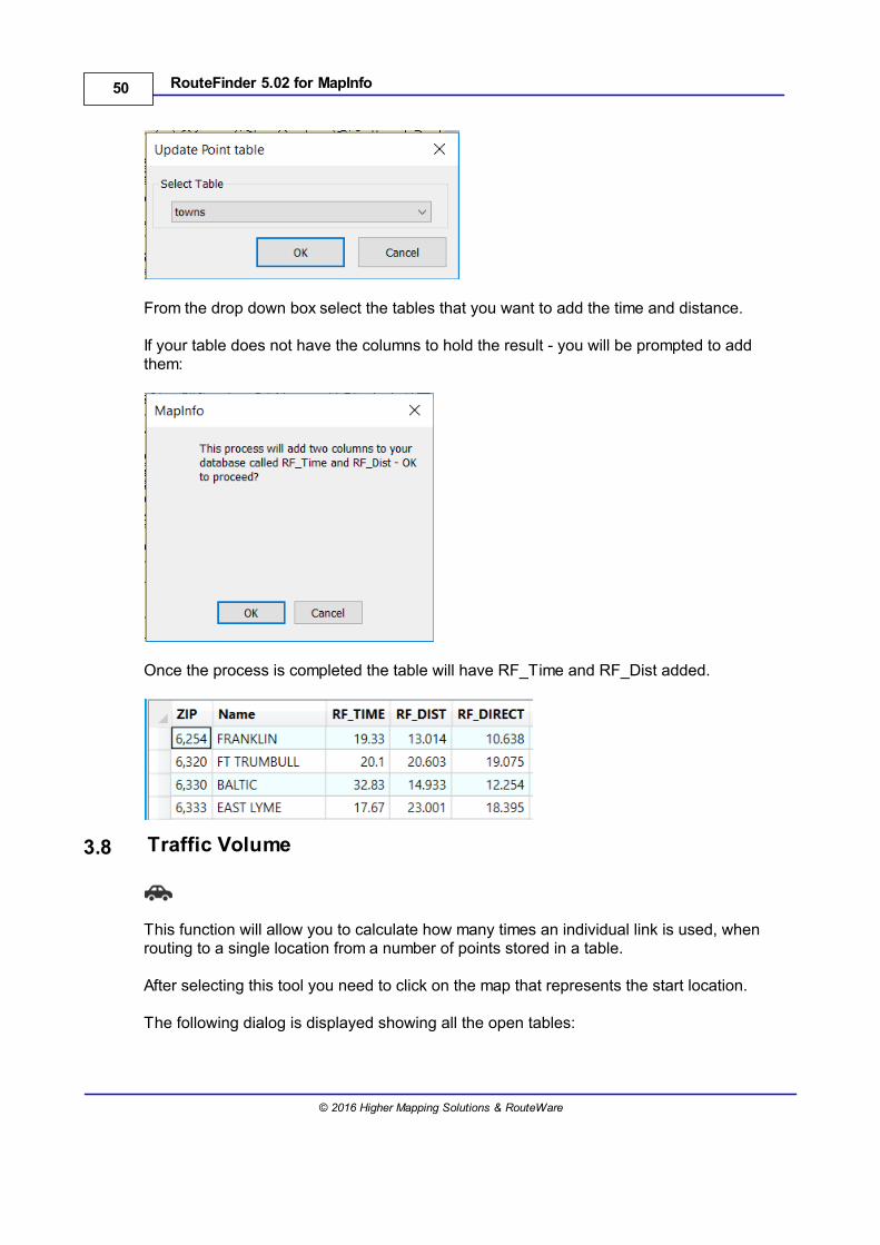
From the drop down box select the tables that you want to add the time and distance.
If your table does not have the columns to hold the result - you will be prompted to addthem:
Once the process is completed the table will have RF_Time and RF_Dist added.
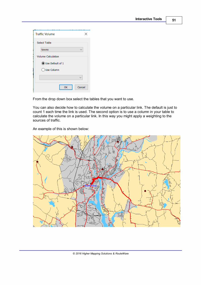
3.8 Traffic Volume
This function will allow you to calculate how many times an individual link is used, whenrouting to a single location from a number of points stored in a table.
After selecting this tool you need to click on the map that represents the start location.
The following dialog is displayed showing all the open tables:
51Interactive Tools
© 2016 Higher Mapping Solutions & RouteWare
From the drop down box select the tables that you want to use.
You can also decide how to calculate the volume on a particular link. The default is just tocount 1 each time the link is used. The second option is to use a column in your table tocalculate the volume on a particular link. In this way you might apply a weighting to thesources of traffic.
An example of this is shown below:

52 RouteFinder 5.02 for MapInfo
© 2016 Higher Mapping Solutions & RouteWare
3.9 Clear Current Result
This function will close all temporary results generated by RouteFinder (not just routes -also isochrones etc.) and clears the results from the message window.

Batch Jobs
Part IV

55Batch Jobs
© 2016 Higher Mapping Solutions & RouteWare
4 Batch Jobs
This is a collection of functions which all require one or two tables as input.
The tables need to contain (mostly) point objects.They should be packed.All records should be geocoded (except for "Route Pairs by coordinate").They can be in any coordinate system (except for "Route Pairs by coordinate").Typically there need to be some kind of ID field.
Large scale matricesDistance Matrix (2)Nearest N centres (2)
Route PairsRoute Pairs (2)Route Pairs by coordinate (1)
Routes with possible driving directionsTravelling Salesman (1)Batch TSP routes (1)Select LocationsRoute on a Joined Table by ID
Snapping to networkAllocate point to network (1)
Isochrones etcDrive Times / Service Area (2)Drive Time from column (2)
It also applies to these interactive toolsUpdate Point File (1)Traffic Volume (2)
(1) = Only possible with native tables with write-access.(2) = Can also use query tables as input
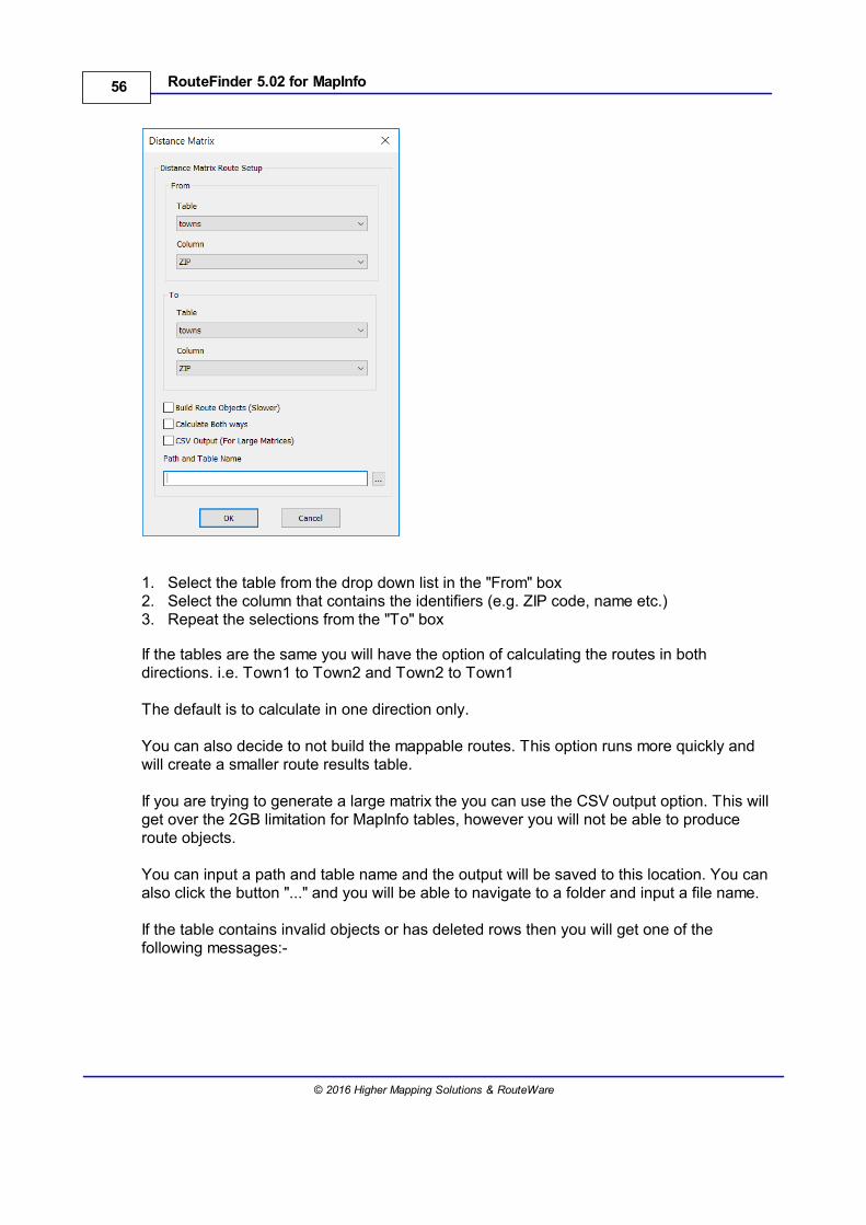
4.1 Distance Matrix
Go to Batch > Distance Matrix
This function will allow generation of a matrix showing time and distance between a numberof points. For example, depots to outlets.
The following dialog is displayed:
56 RouteFinder 5.02 for MapInfo
© 2016 Higher Mapping Solutions & RouteWare
1. Select the table from the drop down list in the "From" box2. Select the column that contains the identifiers (e.g. ZIP code, name etc.)3. Repeat the selections from the "To" box
If the tables are the same you will have the option of calculating the routes in bothdirections. i.e. Town1 to Town2 and Town2 to Town1
The default is to calculate in one direction only.
You can also decide to not build the mappable routes. This option runs more quickly andwill create a smaller route results table.
If you are trying to generate a large matrix the you can use the CSV output option. This willget over the 2GB limitation for MapInfo tables, however you will not be able to produceroute objects.
You can input a path and table name and the output will be saved to this location. You canalso click the button "..." and you will be able to navigate to a folder and input a file name.
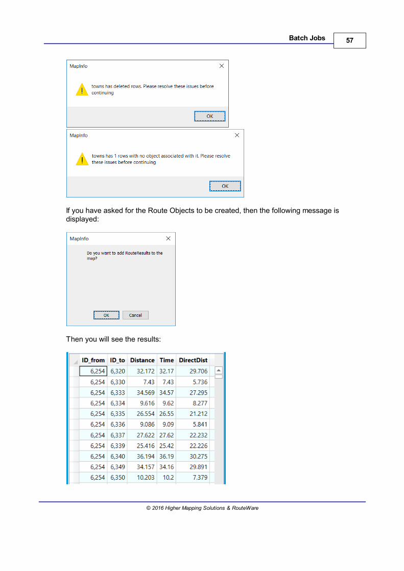
If the table contains invalid objects or has deleted rows then you will get one of thefollowing messages:-
57Batch Jobs
© 2016 Higher Mapping Solutions & RouteWare
If you have asked for the Route Objects to be created, then the following message isdisplayed:
Then you will see the results:
58 RouteFinder 5.02 for MapInfo
© 2016 Higher Mapping Solutions & RouteWare
The distance column will be in the currently selected distance unit, either miles orkilometers. The time will always be returned in minutes.
Route Directions cannot be generated with this option.
If you have used the output to CSV option then you will see a message informing you of theoutput location.
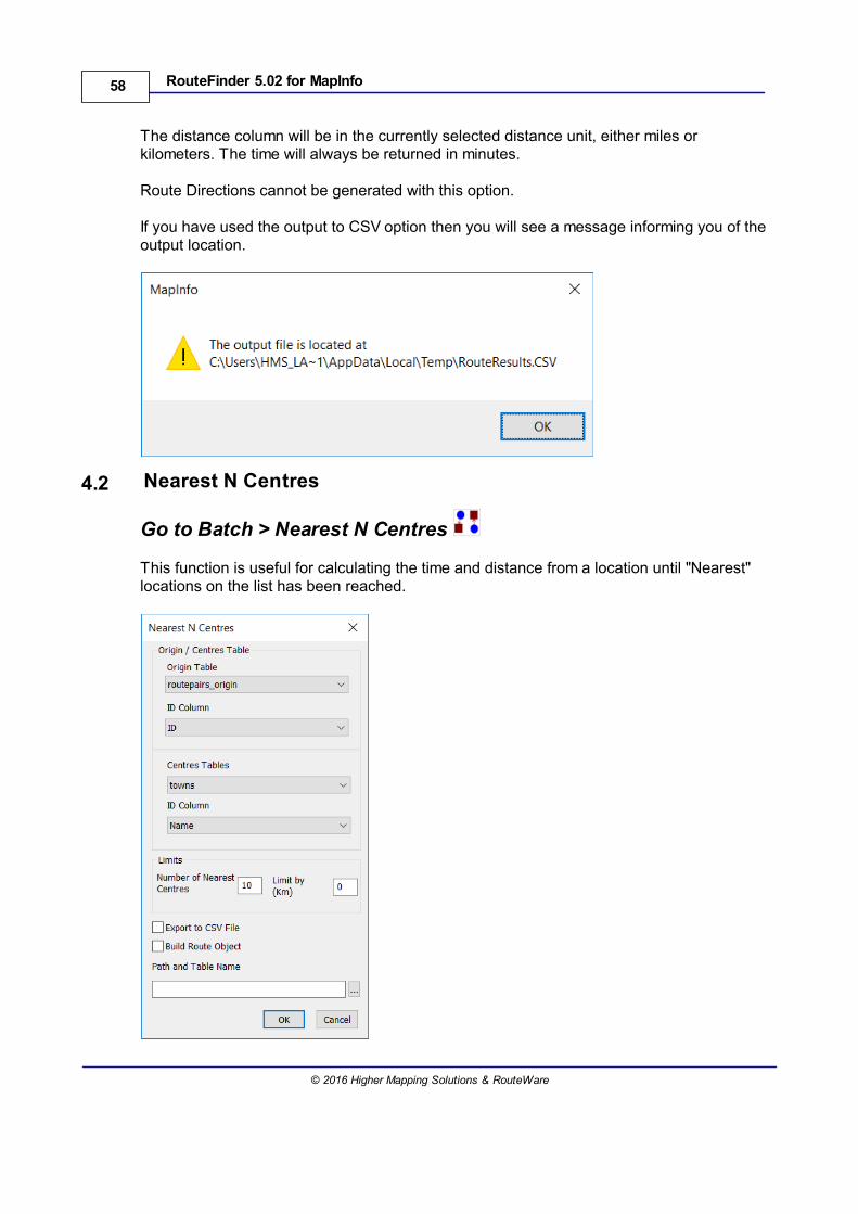
4.2 Nearest N Centres
Go to Batch > Nearest N Centres
This function is useful for calculating the time and distance from a location until "Nearest"locations on the list has been reached.
59Batch Jobs
© 2016 Higher Mapping Solutions & RouteWare
Origin TableUse the drop down boxes to select the table and the column to use as the identifier.
Centres TableUse the drop down boxes to select the table and the column to use as the identifier. This isthen used by the function to get the nearest centres depending on the limits entered.
For efficiency routes are calculated from centres to origins, because there are normallymany more origins than centres.
Therefore you may want to set "Reverse" in the route options to take into account theone way street direction.This will however not reverse turn restrictions. If is important for you to calculate routes tothe centers and have turn restrictions, you should use the Matrix function instead andthen do your own post-processing of the output (sorting and filtering).
Number of Nearest CentresIf a number is entered in here then the function will find the nearest centres until thisnumber is reached. You cannot specify more centres than are in the destinations table.
Time LimitIf a number is entered into this box then it is used to find the nearest centres within the timelimitation.
Build Route ObjectIf you use this option then you will get routes that can be displayed on a Map.
Export to CSV FileIf you are trying to generate a large matrix the you can use the CSV output option. This willget over the 2GB limitation for MapInfo tables.
You can input a path and table name and the output will be saved to this location. You canalso click the button "..." and you will be able to navigate to a folder and input a file name.
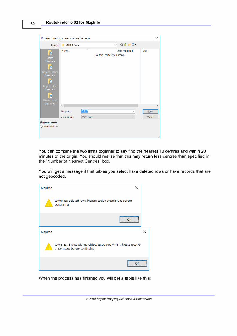
60 RouteFinder 5.02 for MapInfo
© 2016 Higher Mapping Solutions & RouteWare
You can combine the two limits together to say find the nearest 10 centres and within 20minutes of the origin. You should realise that this may return less centres than specified inthe "Number of Nearest Centres" box.
You will get a message if that tables you select have deleted rows or have records that arenot geocoded.
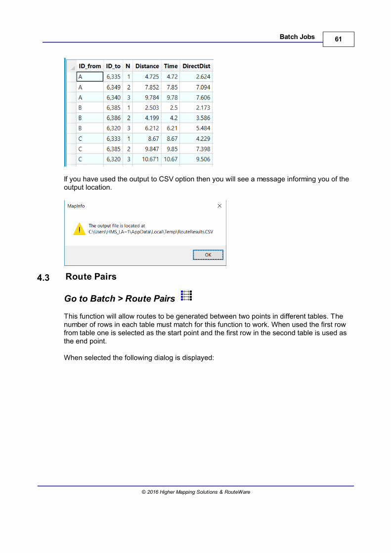
When the process has finished you will get a table like this:
61Batch Jobs
© 2016 Higher Mapping Solutions & RouteWare
If you have used the output to CSV option then you will see a message informing you of theoutput location.
4.3 Route Pairs
Go to Batch > Route Pairs
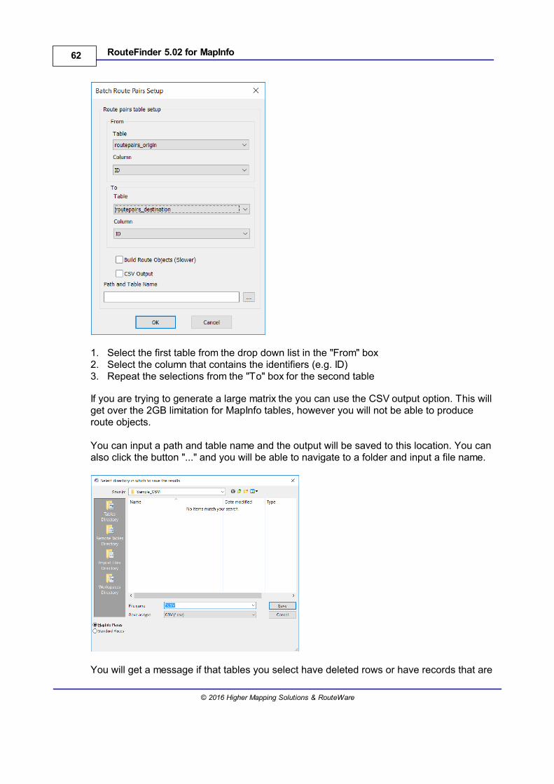
This function will allow routes to be generated between two points in different tables. Thenumber of rows in each table must match for this function to work. When used the first rowfrom table one is selected as the start point and the first row in the second table is used asthe end point.
When selected the following dialog is displayed:
62 RouteFinder 5.02 for MapInfo
© 2016 Higher Mapping Solutions & RouteWare
1. Select the first table from the drop down list in the "From" box2. Select the column that contains the identifiers (e.g. ID)3. Repeat the selections from the "To" box for the second table
If you are trying to generate a large matrix the you can use the CSV output option. This willget over the 2GB limitation for MapInfo tables, however you will not be able to produceroute objects.
You can input a path and table name and the output will be saved to this location. You canalso click the button "..." and you will be able to navigate to a folder and input a file name.
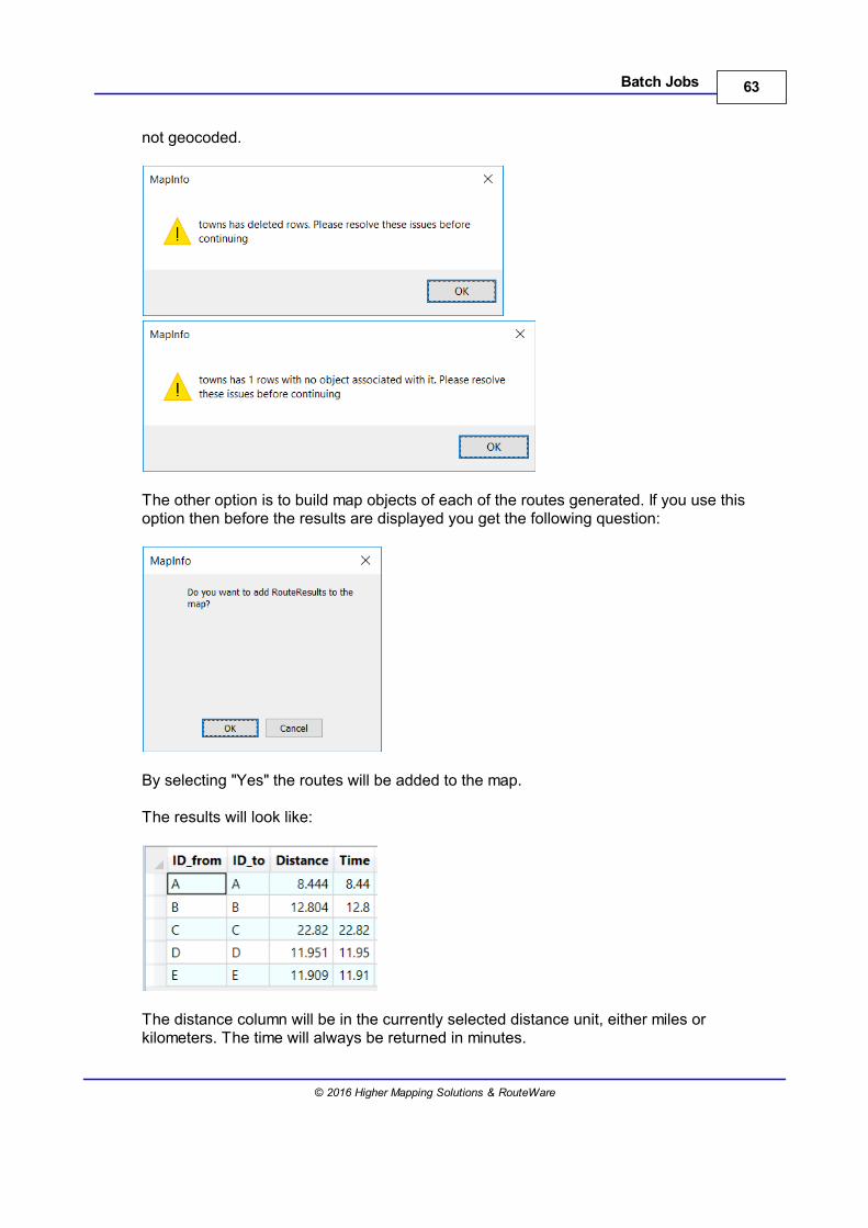
You will get a message if that tables you select have deleted rows or have records that are
63Batch Jobs
© 2016 Higher Mapping Solutions & RouteWare
not geocoded.
The other option is to build map objects of each of the routes generated. If you use thisoption then before the results are displayed you get the following question:
By selecting "Yes" the routes will be added to the map.
The results will look like:
The distance column will be in the currently selected distance unit, either miles orkilometers. The time will always be returned in minutes.
64 RouteFinder 5.02 for MapInfo
© 2016 Higher Mapping Solutions & RouteWare
Route Directions cannot be generated with this option.
If you have used the output to CSV option then you will see a message informing you of theoutput location.
4.4 Route Pairs by Coordinate
Go to Batch > Route Pairs by Coordinate
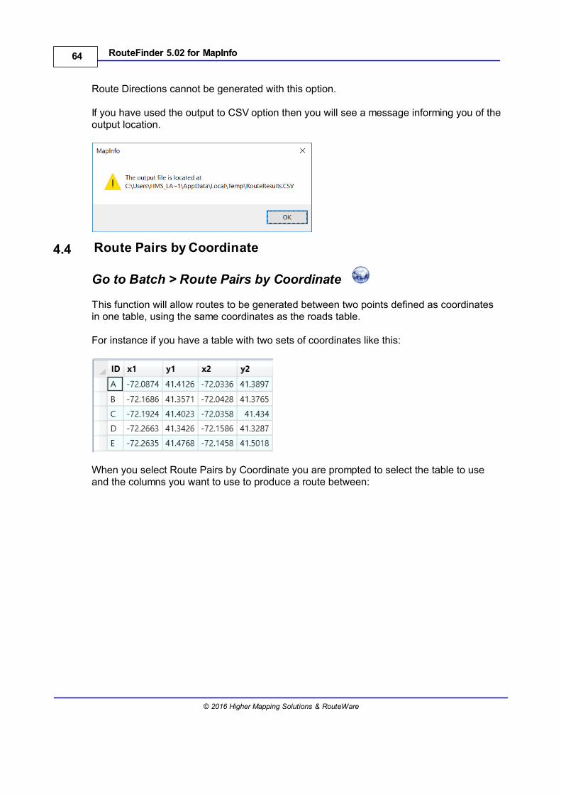
This function will allow routes to be generated between two points defined as coordinatesin one table, using the same coordinates as the roads table.
For instance if you have a table with two sets of coordinates like this:
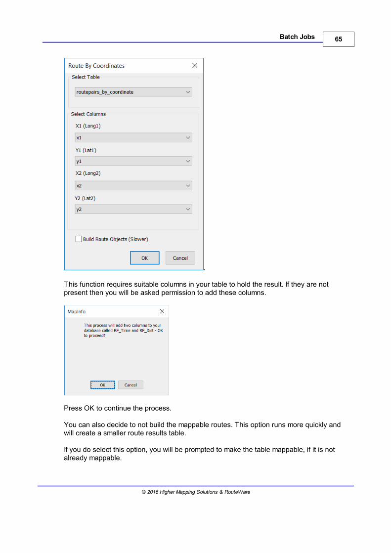
When you select Route Pairs by Coordinate you are prompted to select the table to useand the columns you want to use to produce a route between:
65Batch Jobs
© 2016 Higher Mapping Solutions & RouteWare
.
This function requires suitable columns in your table to hold the result. If they are notpresent then you will be asked permission to add these columns.
Press OK to continue the process.
You can also decide to not build the mappable routes. This option runs more quickly andwill create a smaller route results table.
If you do select this option, you will be prompted to make the table mappable, if it is notalready mappable.
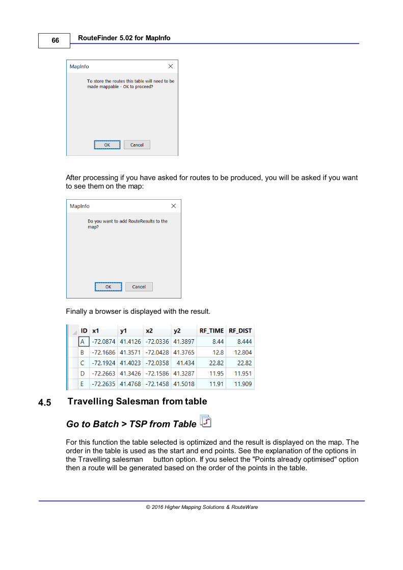
66 RouteFinder 5.02 for MapInfo
© 2016 Higher Mapping Solutions & RouteWare
After processing if you have asked for routes to be produced, you will be asked if you wantto see them on the map:
Finally a browser is displayed with the result.
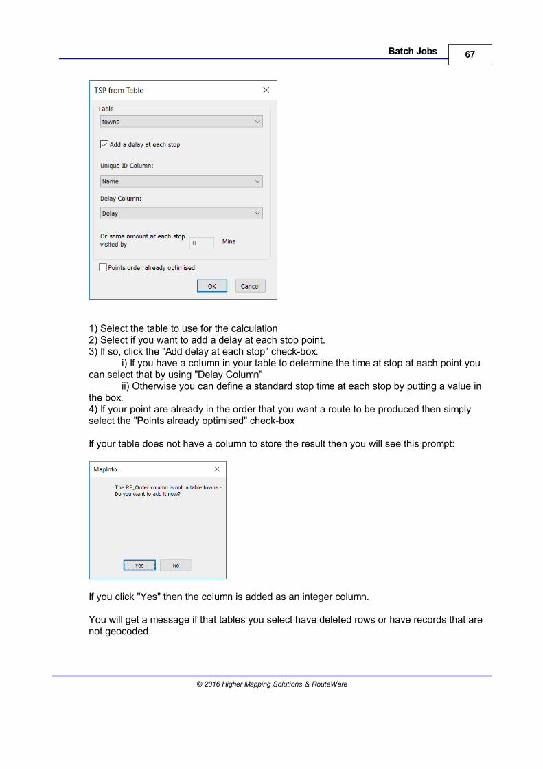
4.5 Travelling Salesman from table
Go to Batch > TSP from Table
For this function the table selected is optimized and the result is displayed on the map. Theorder in the table is used as the start and end points. See the explanation of the options inthe Travelling salesman button option. If you select the "Points already optimised" optionthen a route will be generated based on the order of the points in the table.
67Batch Jobs
© 2016 Higher Mapping Solutions & RouteWare
1) Select the table to use for the calculation2) Select if you want to add a delay at each stop point.3) If so, click the "Add delay at each stop" check-box.
i) If you have a column in your table to determine the time at stop at each point youcan select that by using "Delay Column"
ii) Otherwise you can define a standard stop time at each stop by putting a value inthe box.4) If your point are already in the order that you want a route to be produced then simplyselect the "Points already optimised" check-box
If your table does not have a column to store the result then you will see this prompt:
If you click "Yes" then the column is added as an integer column.
You will get a message if that tables you select have deleted rows or have records that arenot geocoded.
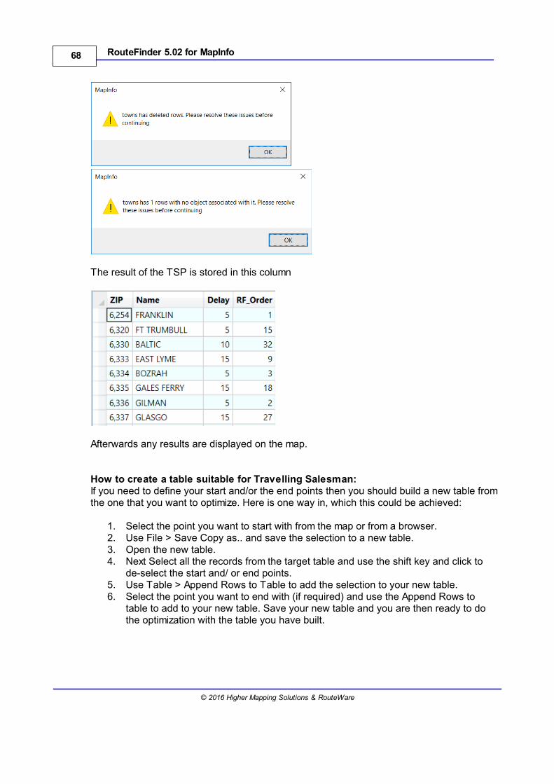
68 RouteFinder 5.02 for MapInfo
© 2016 Higher Mapping Solutions & RouteWare
The result of the TSP is stored in this column
Afterwards any results are displayed on the map.
How to create a table suitable for Travelling Salesman:If you need to define your start and/or the end points then you should build a new table fromthe one that you want to optimize. Here is one way in, which this could be achieved:
1. Select the point you want to start with from the map or from a browser. 2. Use File > Save Copy as.. and save the selection to a new table.3. Open the new table.4. Next Select all the records from the target table and use the shift key and click to
de-select the start and/ or end points.5. Use Table > Append Rows to Table to add the selection to your new table.6. Select the point you want to end with (if required) and use the Append Rows to
table to add to your new table. Save your new table and you are then ready to dothe optimization with the table you have built.
69Batch Jobs
© 2016 Higher Mapping Solutions & RouteWare
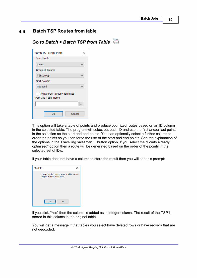
4.6 Batch TSP Routes from table
Go to Batch > Batch TSP from Table
This option will take a table of points and produce optimized routes based on an ID columnin the selected table. The program will select out each ID and use the first and/or last pointsin the selection as the start and end points. You can optionally select a further column toorder the points so you can force the use of the start and end points. See the explanation ofthe options in the Travelling salesman button option. If you select the "Points alreadyoptimised" option then a route will be generated based on the order of the points in theselected set of ID's.
If your table does not have a column to store the result then you will see this prompt:
If you click "Yes" then the column is added as in integer column. The result of the TSP isstored in this column in the original table.
You will get a message if that tables you select have deleted rows or have records that arenot geocoded.
70 RouteFinder 5.02 for MapInfo
© 2016 Higher Mapping Solutions & RouteWare
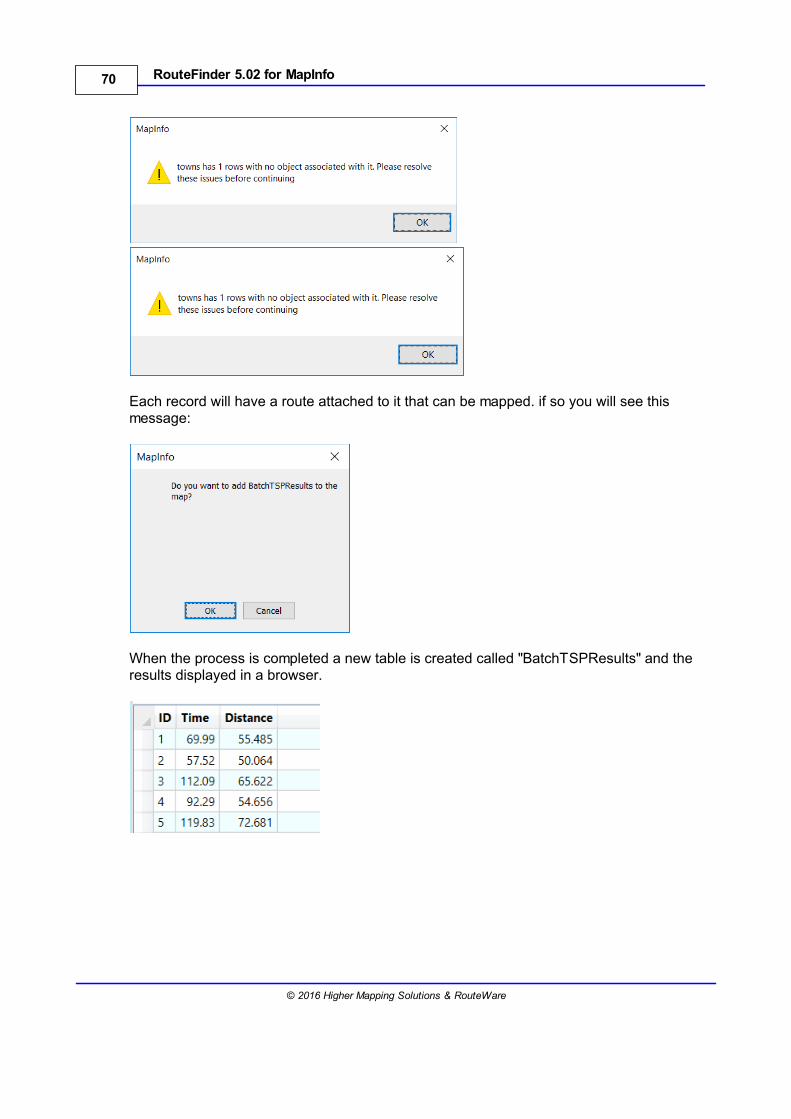
Each record will have a route attached to it that can be mapped. if so you will see thismessage:
When the process is completed a new table is created called "BatchTSPResults" and theresults displayed in a browser.
71Batch Jobs
© 2016 Higher Mapping Solutions & RouteWare
4.7 Select Locations
Go to Batch > Select Locations
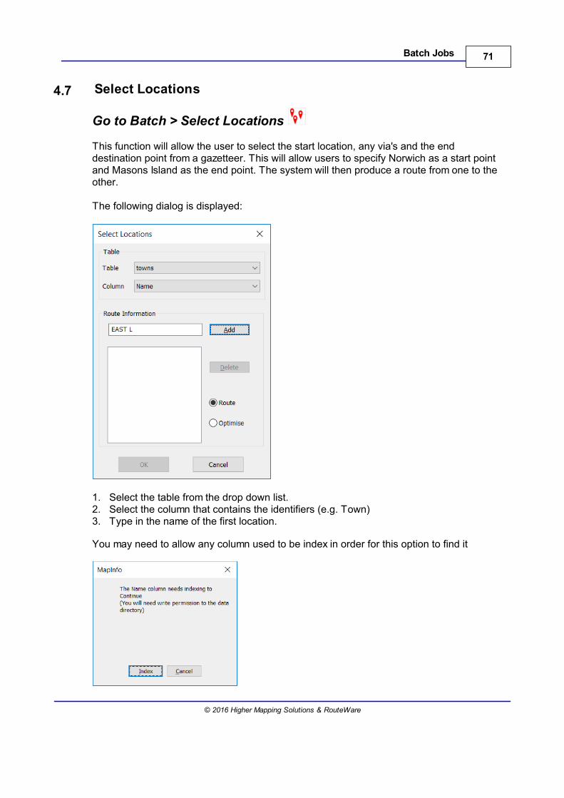
This function will allow the user to select the start location, any via's and the enddestination point from a gazetteer. This will allow users to specify Norwich as a start pointand Masons Island as the end point. The system will then produce a route from one to theother.
The following dialog is displayed:
1. Select the table from the drop down list.2. Select the column that contains the identifiers (e.g. Town)3. Type in the name of the first location.
You may need to allow any column used to be index in order for this option to find it

72 RouteFinder 5.02 for MapInfo
© 2016 Higher Mapping Solutions & RouteWare
4. Click on the "Add" Button. If the location is not found in the table then close matches aredisplayed for the user to select from
5. The location is displayed in the list box.
6. Repeat steps 3-5 to add locations. At least two must be selected.7. Select between generating a "Route" and/or optimizing the route between the selected
points.
73Batch Jobs
© 2016 Higher Mapping Solutions & RouteWare
8. Click on the OK button and the locations are processed and displayed on the map.9. If you add a location by mistake then you can select the location from the list box and
then press the Delete button.
4.8 Route on a Joined Table by ID
Go to Batch > Route on Tables Joined by ID
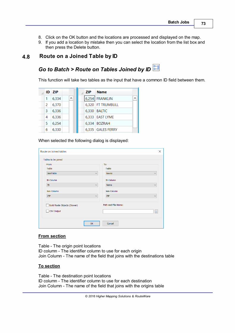
This function will take two tables as the input that have a common ID field between them.
When selected the following dialog is displayed:
From section
Table - The origin point locationsID column - The identifier column to use for each originJoin Column - The name of the field that joins with the destinations table
To section
Table - The destination point locationsID column - The identifier column to use for each destinationJoin Column - The name of the field that joins with the origins table
74 RouteFinder 5.02 for MapInfo
© 2016 Higher Mapping Solutions & RouteWare
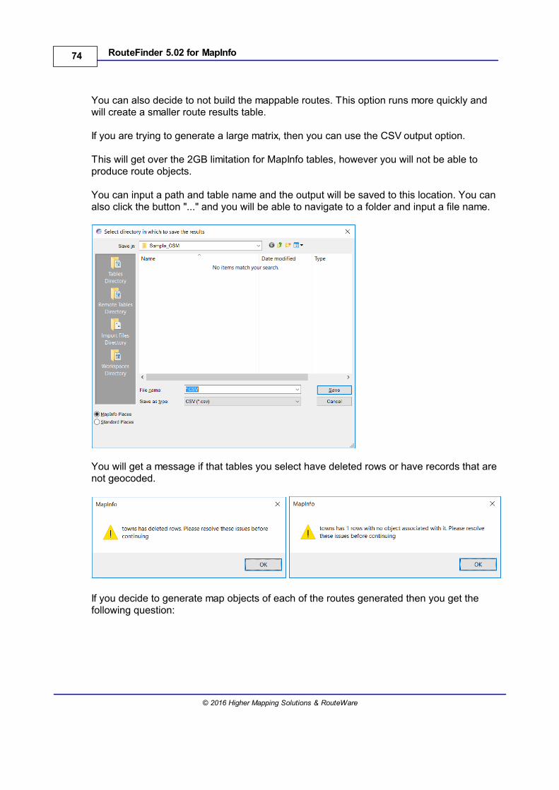
You can also decide to not build the mappable routes. This option runs more quickly andwill create a smaller route results table.
If you are trying to generate a large matrix, then you can use the CSV output option.
This will get over the 2GB limitation for MapInfo tables, however you will not be able toproduce route objects.
You can input a path and table name and the output will be saved to this location. You canalso click the button "..." and you will be able to navigate to a folder and input a file name.
You will get a message if that tables you select have deleted rows or have records that arenot geocoded.
If you decide to generate map objects of each of the routes generated then you get thefollowing question:
75Batch Jobs
© 2016 Higher Mapping Solutions & RouteWare
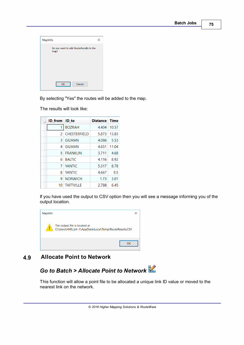
By selecting "Yes" the routes will be added to the map.
The results will look like:
If you have used the output to CSV option then you will see a message informing you of theoutput location.
4.9 Allocate Point to Network
Go to Batch > Allocate Point to Network
This function will allow a point file to be allocated a unique link ID value or moved to thenearest link on the network.
76 RouteFinder 5.02 for MapInfo
© 2016 Higher Mapping Solutions & RouteWare
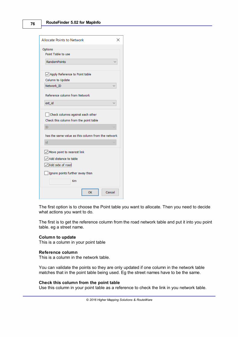
The first option is to choose the Point table you want to allocate. Then you need to decidewhat actions you want to do.
The first is to get the reference column from the road network table and put it into you pointtable. eg a street name.
Column to updateThis is a column in your point table
Reference columnThis is a column in the network table.
You can validate the points so they are only updated if one column in the network tablematches that in the point table being used. Eg the street names have to be the same.
Check this column from the point tableUse this column in your point table as a reference to check the link in you network table.
77Batch Jobs
© 2016 Higher Mapping Solutions & RouteWare
Has the same value as this column from the network tableThis is a column in your network table - it will be checked against the point being allocated.If the references are the same the columns will be updated.
Move Point to nearest linkBy checking this option the point will be updated with the new coordinates of the nearestpoint on the link.
Add distance to tableThis option will add the "DisttoNetwork" column to the point table indicating the distance ofthat point to the nearest link on the network.
Add side of the road This option will add "SideofRoad" to the point table.0 = Right side of the road1 = Left side of the road
Ignore points further away thanIf the distance from the point to the nearest link is greater than the distance specified in thebox then it is ignored.
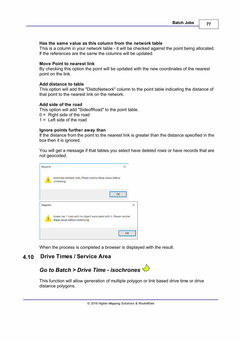
You will get a message if that tables you select have deleted rows or have records that arenot geocoded.
When the process is completed a browser is displayed with the result.
4.10 Drive Times / Service Area
Go to Batch > Drive Time - isochrones
This function will allow generation of multiple polygon or link based drive time or drivedistance polygons.
78 RouteFinder 5.02 for MapInfo
© 2016 Higher Mapping Solutions & RouteWare
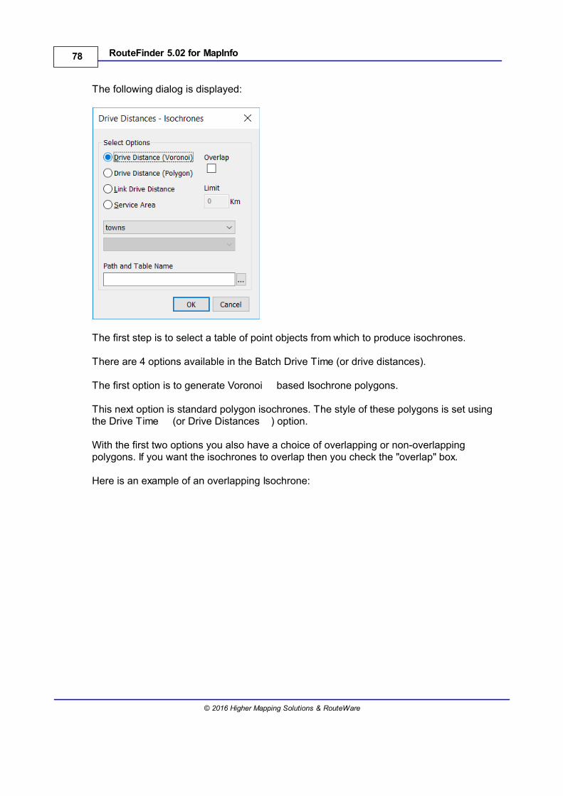
The following dialog is displayed:
The first step is to select a table of point objects from which to produce isochrones.
There are 4 options available in the Batch Drive Time (or drive distances).
The first option is to generate Voronoi based Isochrone polygons.
This next option is standard polygon isochrones. The style of these polygons is set usingthe Drive Time (or Drive Distances ) option.
With the first two options you also have a choice of overlapping or non-overlappingpolygons. If you want the isochrones to overlap then you check the "overlap" box.
Here is an example of an overlapping Isochrone:
79Batch Jobs
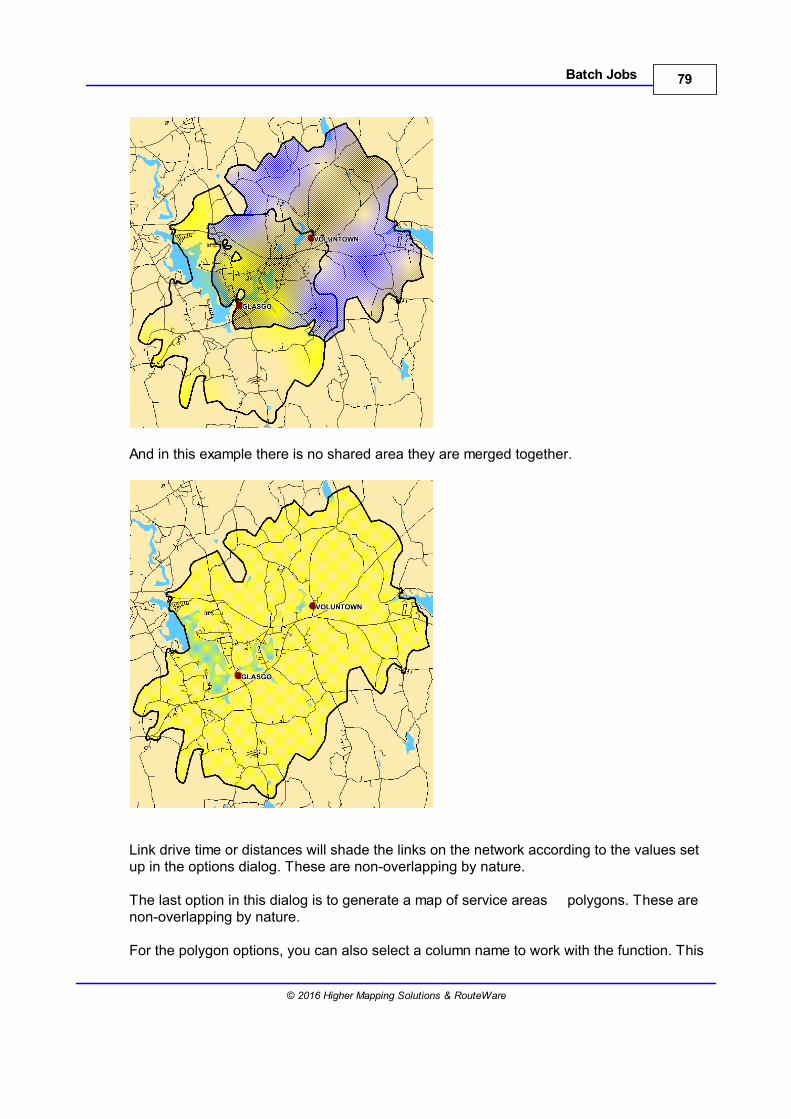
© 2016 Higher Mapping Solutions & RouteWare
And in this example there is no shared area they are merged together.
Link drive time or distances will shade the links on the network according to the values setup in the options dialog. These are non-overlapping by nature.
The last option in this dialog is to generate a map of service areas polygons. These arenon-overlapping by nature.
For the polygon options, you can also select a column name to work with the function. This
80 RouteFinder 5.02 for MapInfo
© 2016 Higher Mapping Solutions & RouteWare
will then update the polygons that are created with the value of the selected field for eachpoint. This will allow you to easily identify which polygons have been created for each pointon your map.
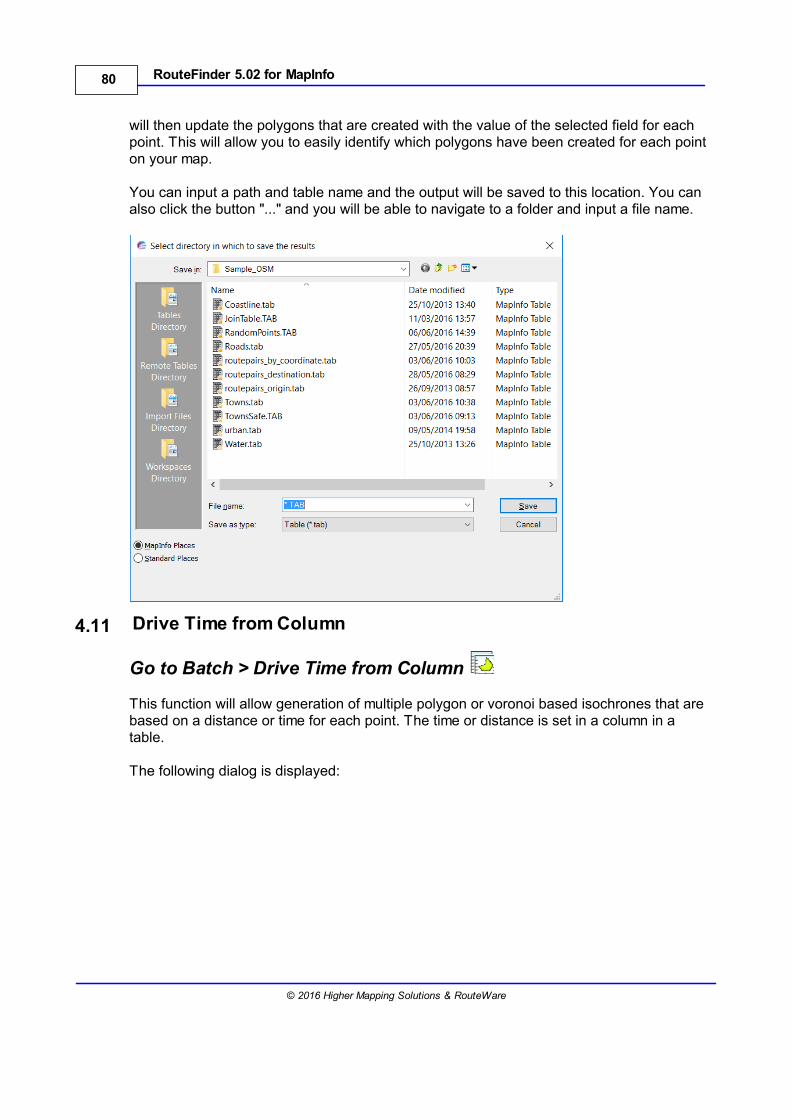
You can input a path and table name and the output will be saved to this location. You canalso click the button "..." and you will be able to navigate to a folder and input a file name.
4.11 Drive Time from Column
Go to Batch > Drive Time from Column
This function will allow generation of multiple polygon or voronoi based isochrones that arebased on a distance or time for each point. The time or distance is set in a column in atable.
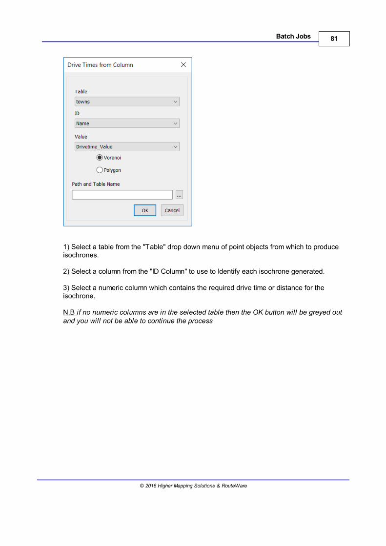
The following dialog is displayed:
81Batch Jobs
© 2016 Higher Mapping Solutions & RouteWare
1) Select a table from the "Table" drop down menu of point objects from which to produceisochrones.
2) Select a column from the "ID Column" to use to Identify each isochrone generated.
3) Select a numeric column which contains the required drive time or distance for theisochrone.
N.B if no numeric columns are in the selected table then the OK button will be greyed outand you will not be able to continue the process


Restrictions
Part V

85Restrictions
© 2016 Higher Mapping Solutions & RouteWare
5 Restrictions
You can manage restrictions through the user interface. This includes turn restrictions, oneway streets, height, width and weight restrictions.You can also manage "avoid" bits, closing roads and slowing roads.
You can make changes to the network, but they are only permanently applied to thenetwork if you save the restrictions.
The functionality is accessed via the Restrictions menu item.
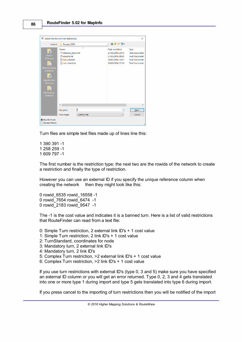
5.1 Import Turn File
Go to Restrictions > Import Turn File
This options will take a text file of predefined turn restrictions and create the binary files foruse in RouteFinder.
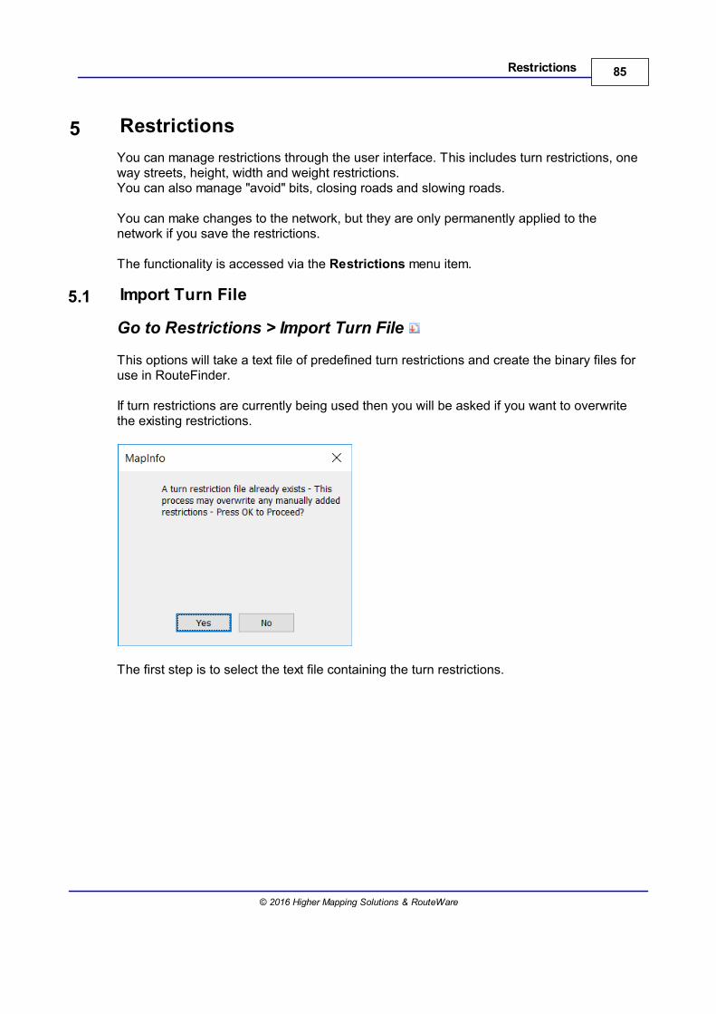
If turn restrictions are currently being used then you will be asked if you want to overwritethe existing restrictions.
The first step is to select the text file containing the turn restrictions.
86 RouteFinder 5.02 for MapInfo
© 2016 Higher Mapping Solutions & RouteWare
Turn files are simple text files made up of lines line this:
1 390 391 -11 258 259 -11 609 797 -1
The first number is the restriction type; the next two are the rowids of the network to createa restriction and finally the type of restriction.
However you can use an external ID if you specify the unique reference column when creating the network then they might look like this:
0 rowid_6535 rowid_16558 -10 rowid_7654 rowid_6474 -10 rowid_2183 rowid_9547 -1
The -1 is the cost value and indicates it is a banned turn. Here is a list of valid restrictionsthat RouteFinder can read from a text file:
0: Simple Turn restriction, 2 external link ID's + 1 cost value 1: Simple Turn restriction, 2 link ID's + 1 cost value 2: TurnStandard, coordinates for node 3: Mandatory turn, 2 external link ID's 4: Mandatory turn, 2 link ID's 5: Complex Turn restriction, >2 external link ID's + 1 cost value 6: Complex Turn restriction, >2 link ID's + 1 cost value
If you use turn restrictions with external ID's (type 0, 3 and 5) make sure you have specifiedan external ID column or you will get an error returned. Type 0, 2, 3 and 4 gets translatedinto one or more type 1 during import and type 5 gets translated into type 6 during import.
If you press cancel to the importing of turn restrictions then you will be notified of the import
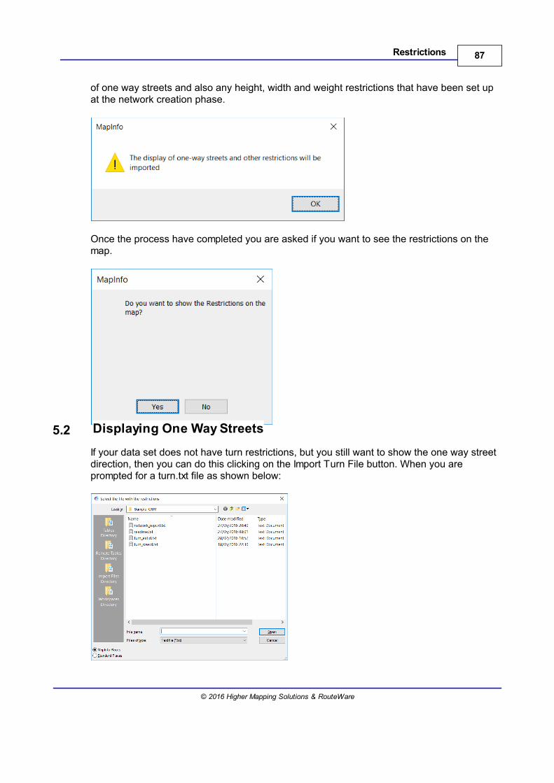
87Restrictions
© 2016 Higher Mapping Solutions & RouteWare
of one way streets and also any height, width and weight restrictions that have been set upat the network creation phase.
Once the process have completed you are asked if you want to see the restrictions on themap.
5.2 Displaying One Way Streets
If your data set does not have turn restrictions, but you still want to show the one way streetdirection, then you can do this clicking on the Import Turn File button. When you areprompted for a turn.txt file as shown below:
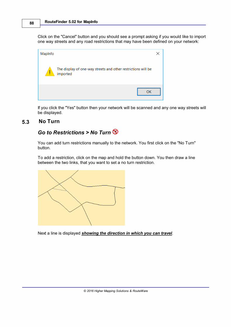
88 RouteFinder 5.02 for MapInfo
© 2016 Higher Mapping Solutions & RouteWare
Click on the "Cancel" button and you should see a prompt asking if you would like to importone way streets and any road restrictions that may have been defined on your network:
If you click the "Yes" button then your network will be scanned and any one way streets willbe displayed.
5.3 No Turn
Go to Restrictions > No Turn
You can add turn restrictions manually to the network. You first click on the "No Turn"button.
To add a restriction, click on the map and hold the button down. You then draw a linebetween the two links, that you want to set a no turn restriction.
Next a line is displayed showing the direction in which you can travel.
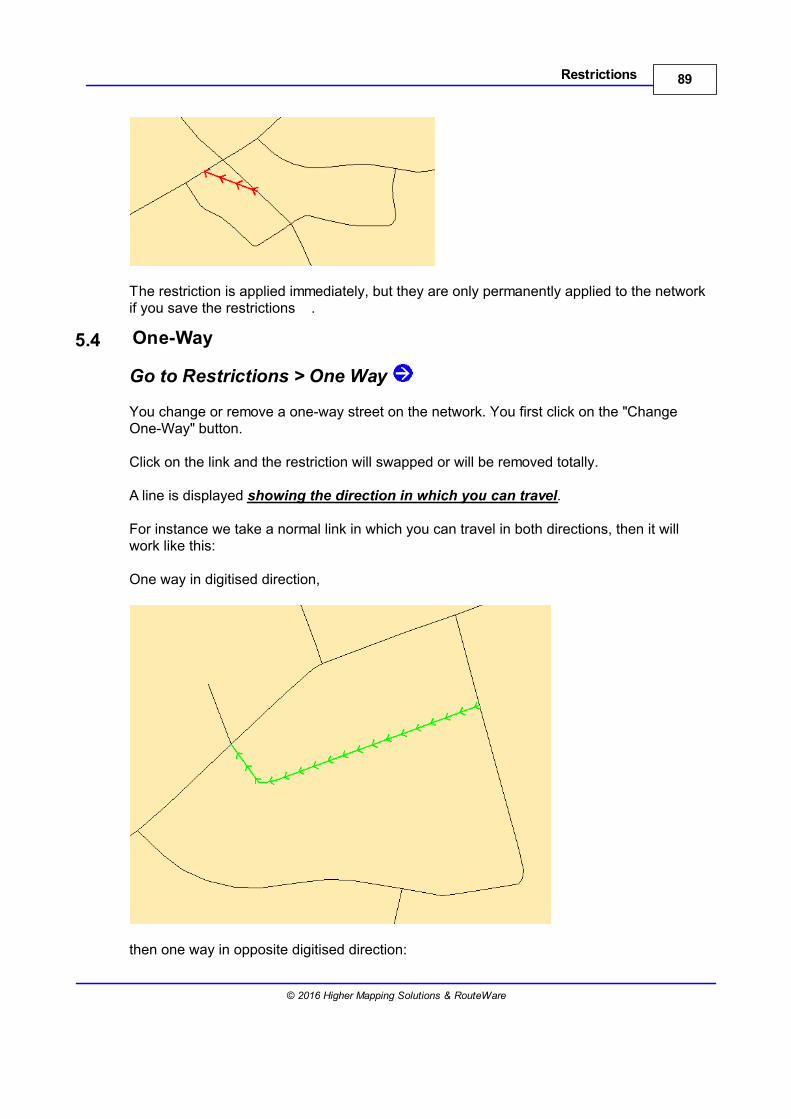
89Restrictions
© 2016 Higher Mapping Solutions & RouteWare
The restriction is applied immediately, but they are only permanently applied to the networkif you save the restrictions .
5.4 One-Way
Go to Restrictions > One Way
You change or remove a one-way street on the network. You first click on the "ChangeOne-Way" button.
Click on the link and the restriction will swapped or will be removed totally.
A line is displayed showing the direction in which you can travel.
For instance we take a normal link in which you can travel in both directions, then it willwork like this:
One way in digitised direction,
then one way in opposite digitised direction:
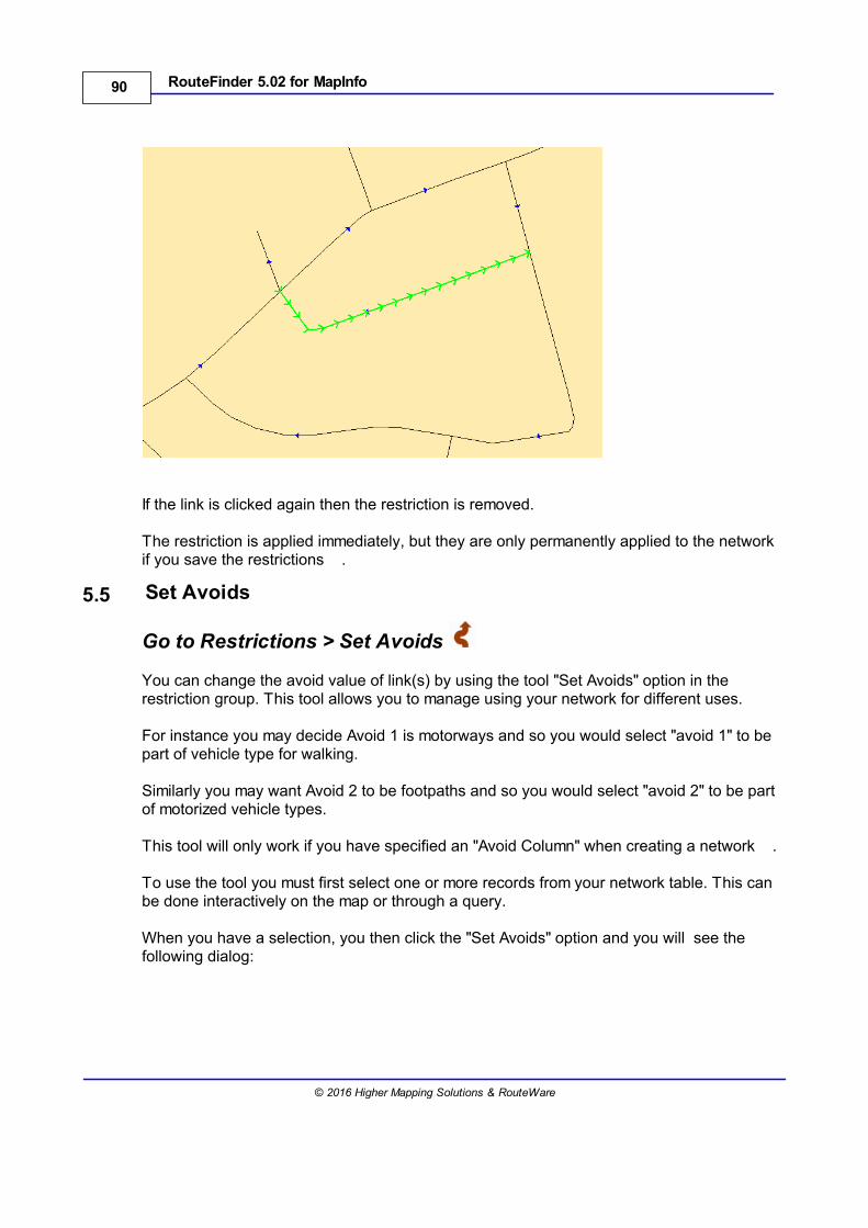
90 RouteFinder 5.02 for MapInfo
© 2016 Higher Mapping Solutions & RouteWare
If the link is clicked again then the restriction is removed.
The restriction is applied immediately, but they are only permanently applied to the networkif you save the restrictions .
5.5 Set Avoids
Go to Restrictions > Set Avoids
You can change the avoid value of link(s) by using the tool "Set Avoids" option in therestriction group. This tool allows you to manage using your network for different uses.
For instance you may decide Avoid 1 is motorways and so you would select "avoid 1" to bepart of vehicle type for walking.
Similarly you may want Avoid 2 to be footpaths and so you would select "avoid 2" to be partof motorized vehicle types.
This tool will only work if you have specified an "Avoid Column" when creating a network .
To use the tool you must first select one or more records from your network table. This canbe done interactively on the map or through a query.
When you have a selection, you then click the "Set Avoids" option and you will see thefollowing dialog:
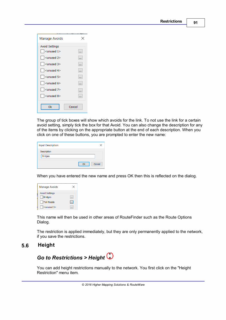
91Restrictions
© 2016 Higher Mapping Solutions & RouteWare
The group of tick boxes will show which avoids for the link. To not use the link for a certainavoid setting, simply tick the box for that Avoid. You can also change the description for anyof the items by clicking on the appropriate button at the end of each description. When youclick on one of these buttons, you are prompted to enter the new name:
When you have entered the new name and press OK then this is reflected on the dialog.
This name will then be used in other areas of RouteFinder such as the Route OptionsDialog.
The restriction is applied immediately, but they are only permanently applied to the network,if you save the restrictions.
5.6 Height
Go to Restrictions > Height
You can add height restrictions manually to the network. You first click on the "HeightRestriction" menu item.
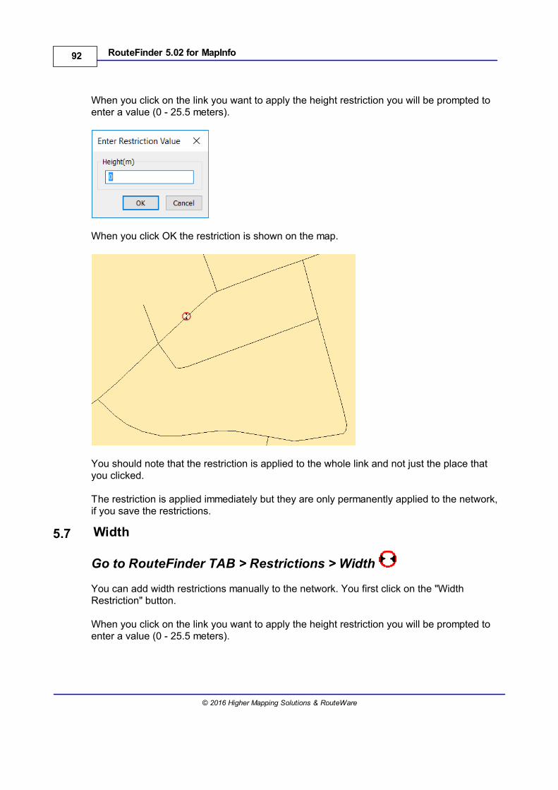
92 RouteFinder 5.02 for MapInfo
© 2016 Higher Mapping Solutions & RouteWare
When you click on the link you want to apply the height restriction you will be prompted toenter a value (0 - 25.5 meters).
When you click OK the restriction is shown on the map.
You should note that the restriction is applied to the whole link and not just the place thatyou clicked.
The restriction is applied immediately but they are only permanently applied to the network,if you save the restrictions.
5.7 Width
Go to RouteFinder TAB > Restrictions > Width
You can add width restrictions manually to the network. You first click on the "WidthRestriction" button.
When you click on the link you want to apply the height restriction you will be prompted toenter a value (0 - 25.5 meters).
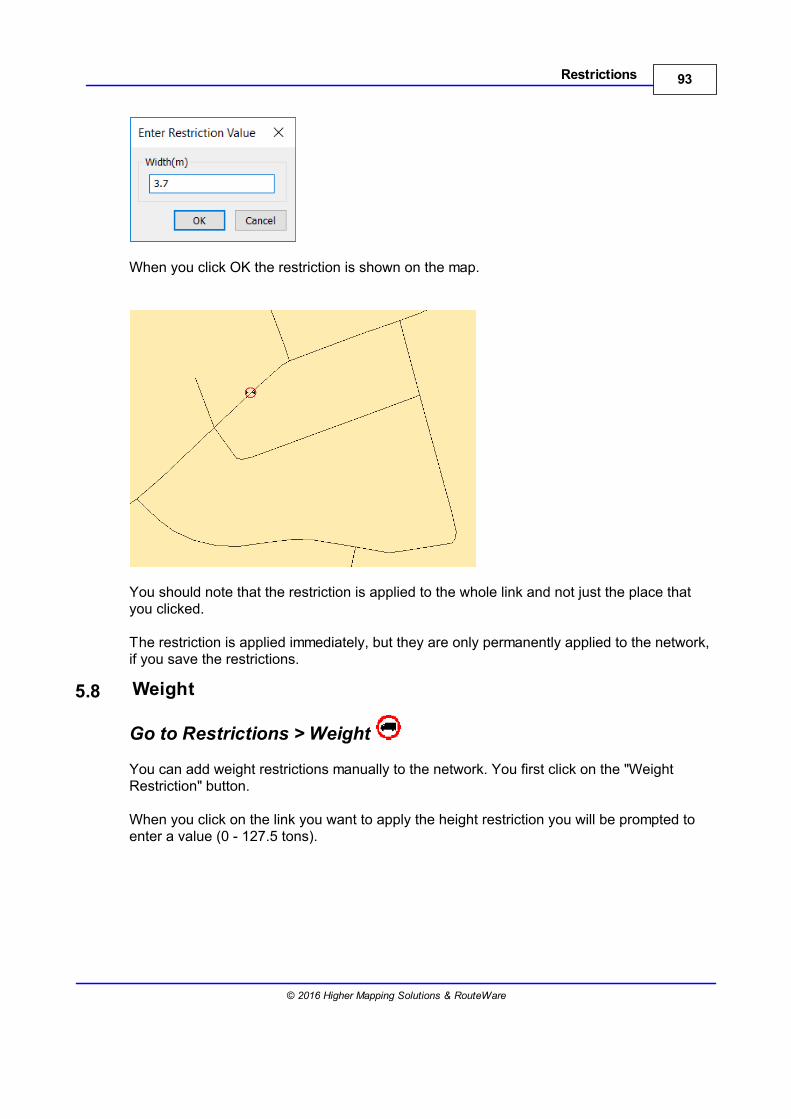
93Restrictions
© 2016 Higher Mapping Solutions & RouteWare
When you click OK the restriction is shown on the map.
You should note that the restriction is applied to the whole link and not just the place thatyou clicked.
The restriction is applied immediately, but they are only permanently applied to the network,if you save the restrictions.
5.8 Weight
Go to Restrictions > Weight
You can add weight restrictions manually to the network. You first click on the "WeightRestriction" button.
When you click on the link you want to apply the height restriction you will be prompted toenter a value (0 - 127.5 tons).
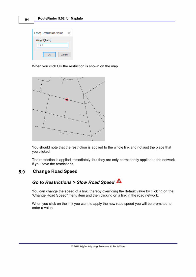
94 RouteFinder 5.02 for MapInfo
© 2016 Higher Mapping Solutions & RouteWare
When you click OK the restriction is shown on the map.
You should note that the restriction is applied to the whole link and not just the place thatyou clicked.
The restriction is applied immediately, but they are only permanently applied to the network,if you save the restrictions.
5.9 Change Road Speed
Go to Restrictions > Slow Road Speed
You can change the speed of a link, thereby overriding the default value by clicking on the"Change Road Speed" menu item and then clicking on a link in the road network.
When you click on the link you want to apply the new road speed you will be prompted toenter a value.
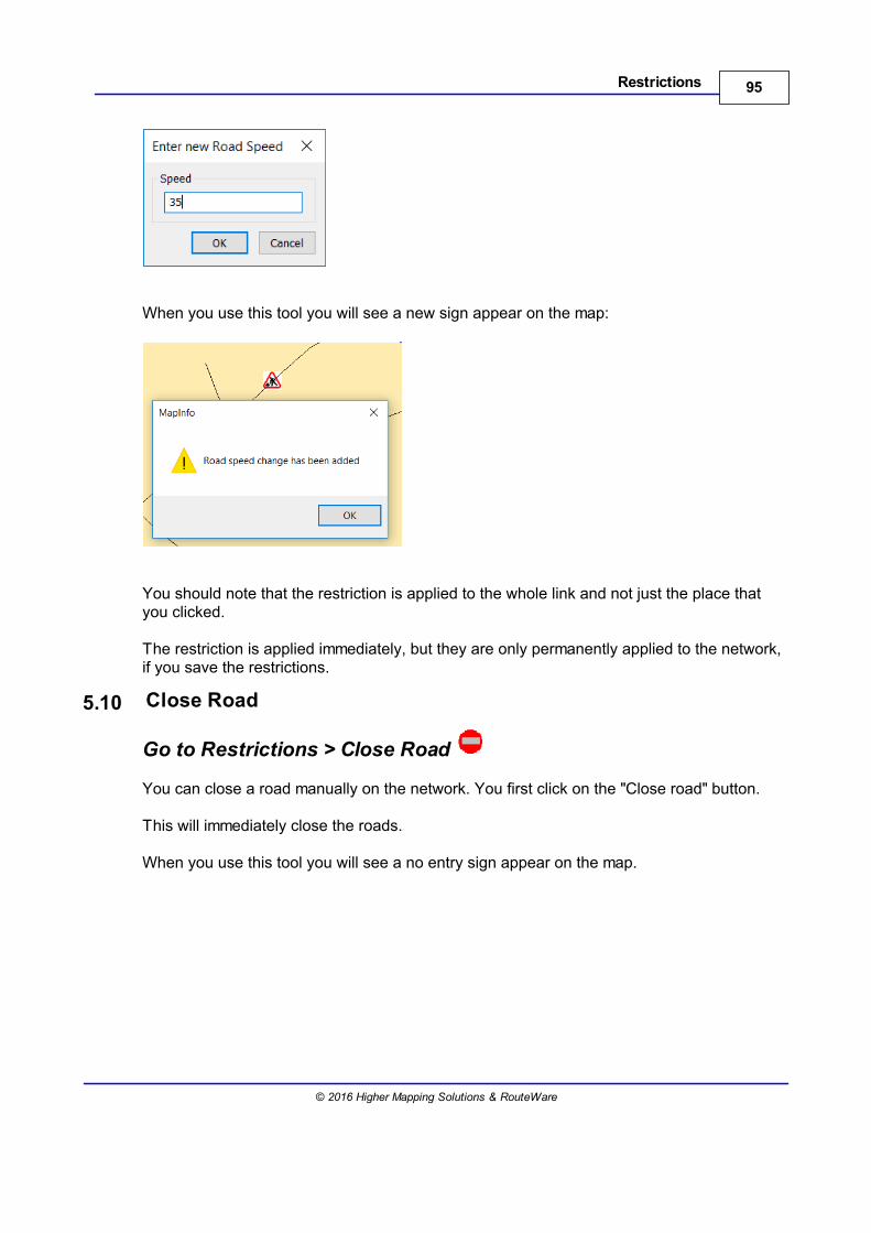
95Restrictions
© 2016 Higher Mapping Solutions & RouteWare
When you use this tool you will see a new sign appear on the map:
You should note that the restriction is applied to the whole link and not just the place thatyou clicked.
The restriction is applied immediately, but they are only permanently applied to the network,if you save the restrictions.
5.10 Close Road
Go to Restrictions > Close Road
You can close a road manually on the network. You first click on the "Close road" button.
This will immediately close the roads.
When you use this tool you will see a no entry sign appear on the map.
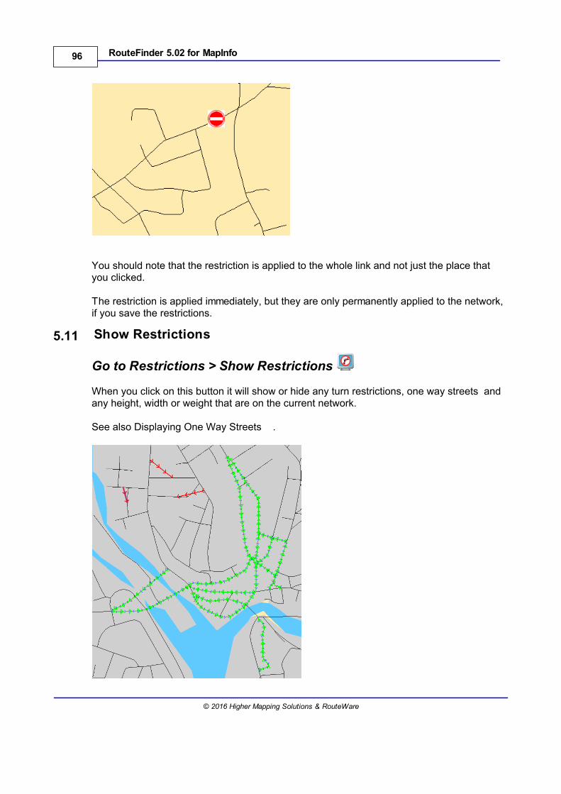
96 RouteFinder 5.02 for MapInfo
© 2016 Higher Mapping Solutions & RouteWare
You should note that the restriction is applied to the whole link and not just the place thatyou clicked.
The restriction is applied immediately, but they are only permanently applied to the network,if you save the restrictions.
5.11 Show Restrictions
Go to Restrictions > Show Restrictions
When you click on this button it will show or hide any turn restrictions, one way streets andany height, width or weight that are on the current network.
See also Displaying One Way Streets .
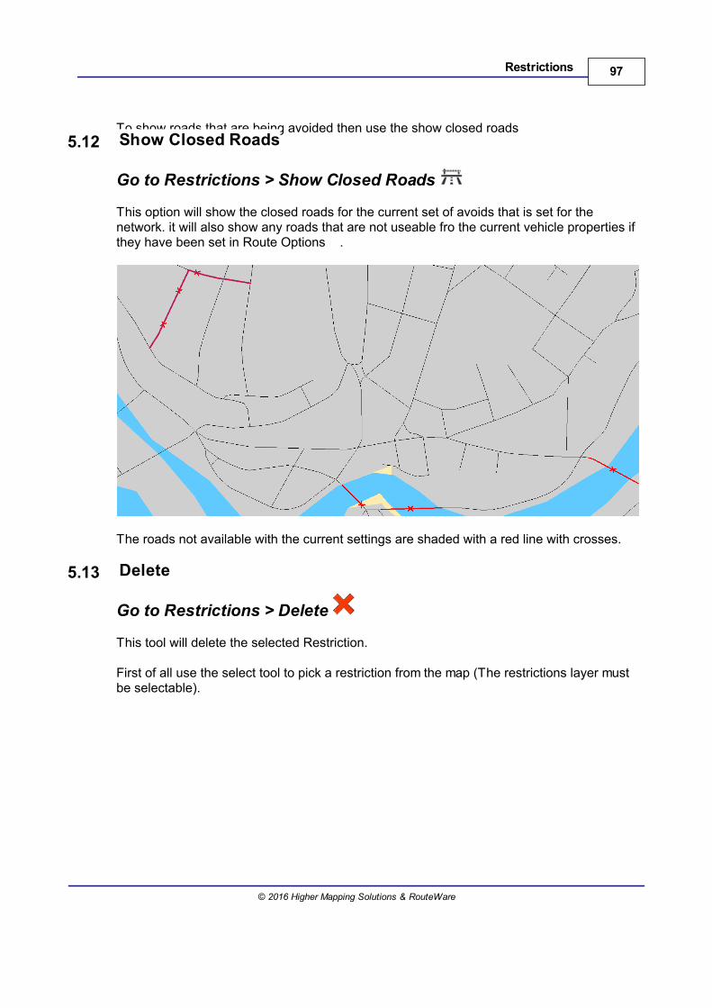
97Restrictions
© 2016 Higher Mapping Solutions & RouteWare
To show roads that are being avoided then use the show closed roads5.12 Show Closed Roads
Go to Restrictions > Show Closed Roads
This option will show the closed roads for the current set of avoids that is set for thenetwork. it will also show any roads that are not useable fro the current vehicle properties ifthey have been set in Route Options .
The roads not available with the current settings are shaded with a red line with crosses.
5.13 Delete
Go to Restrictions > Delete
This tool will delete the selected Restriction.
First of all use the select tool to pick a restriction from the map (The restrictions layer mustbe selectable).
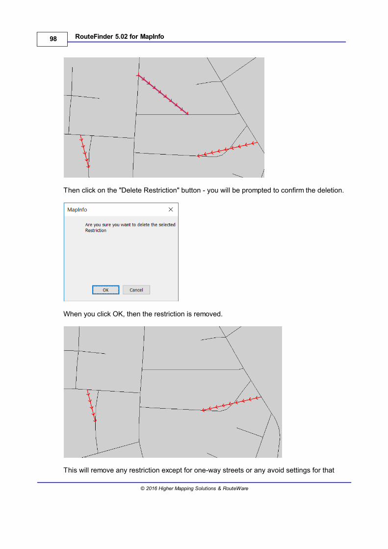
98 RouteFinder 5.02 for MapInfo
© 2016 Higher Mapping Solutions & RouteWare
Then click on the "Delete Restriction" button - you will be prompted to confirm the deletion.
When you click OK, then the restriction is removed.
This will remove any restriction except for one-way streets or any avoid settings for that
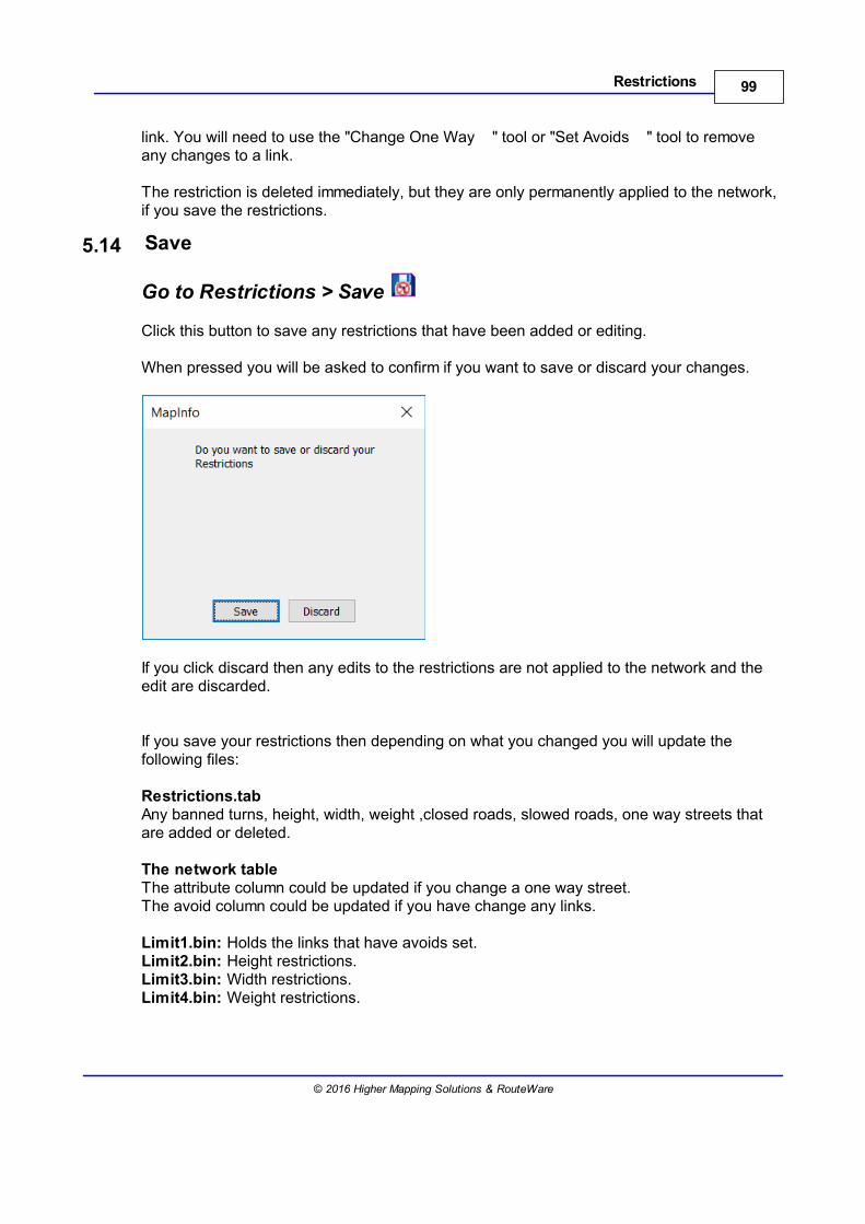
99Restrictions
© 2016 Higher Mapping Solutions & RouteWare
link. You will need to use the "Change One Way " tool or "Set Avoids " tool to removeany changes to a link.
The restriction is deleted immediately, but they are only permanently applied to the network,if you save the restrictions.
5.14 Save
Go to Restrictions > Save
Click this button to save any restrictions that have been added or editing.
When pressed you will be asked to confirm if you want to save or discard your changes.
If you click discard then any edits to the restrictions are not applied to the network and theedit are discarded.
If you save your restrictions then depending on what you changed you will update thefollowing files:
Restrictions.tabAny banned turns, height, width, weight ,closed roads, slowed roads, one way streets thatare added or deleted.
The network tableThe attribute column could be updated if you change a one way street.The avoid column could be updated if you have change any links.
Limit1.bin: Holds the links that have avoids set.Limit2.bin: Height restrictions.Limit3.bin: Width restrictions.Limit4.bin: Weight restrictions.


Network Analysis
Part VI

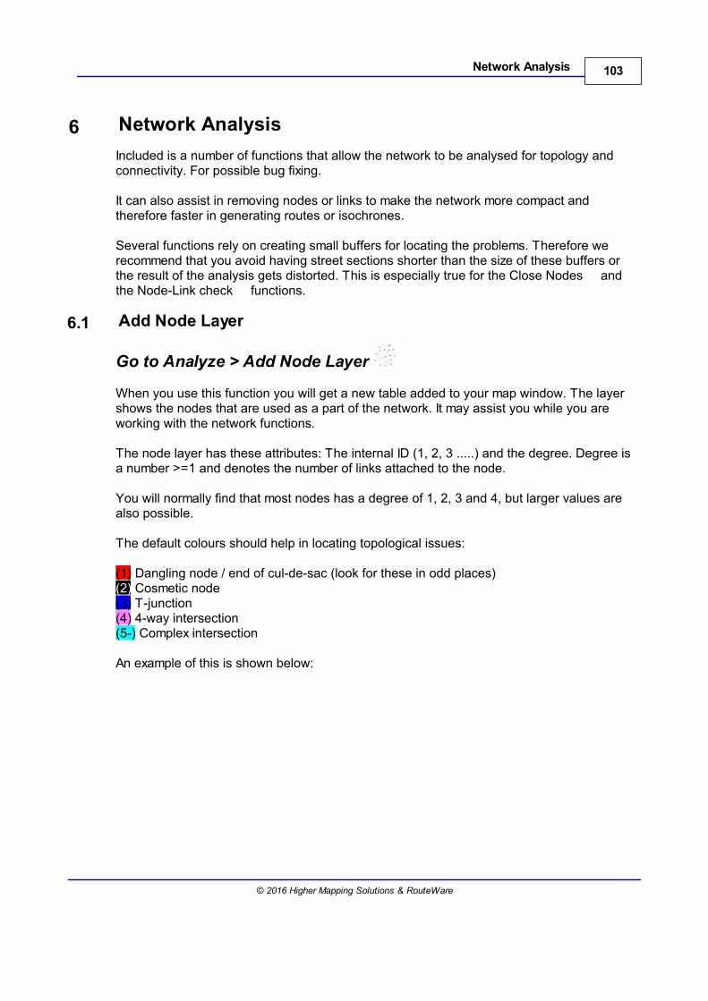
103Network Analysis
© 2016 Higher Mapping Solutions & RouteWare
6 Network Analysis
Included is a number of functions that allow the network to be analysed for topology andconnectivity. For possible bug fixing.
It can also assist in removing nodes or links to make the network more compact andtherefore faster in generating routes or isochrones.
Several functions rely on creating small buffers for locating the problems. Therefore werecommend that you avoid having street sections shorter than the size of these buffers orthe result of the analysis gets distorted. This is especially true for the Close Nodes andthe Node-Link check functions.
6.1 Add Node Layer
Go to Analyze > Add Node Layer
When you use this function you will get a new table added to your map window. The layershows the nodes that are used as a part of the network. It may assist you while you areworking with the network functions.
The node layer has these attributes: The internal ID (1, 2, 3 .....) and the degree. Degree isa number >=1 and denotes the number of links attached to the node.
You will normally find that most nodes has a degree of 1, 2, 3 and 4, but larger values arealso possible.
The default colours should help in locating topological issues:
(1) Dangling node / end of cul-de-sac (look for these in odd places)(2) Cosmetic node(3) T-junction(4) 4-way intersection(5-) Complex intersection
An example of this is shown below:
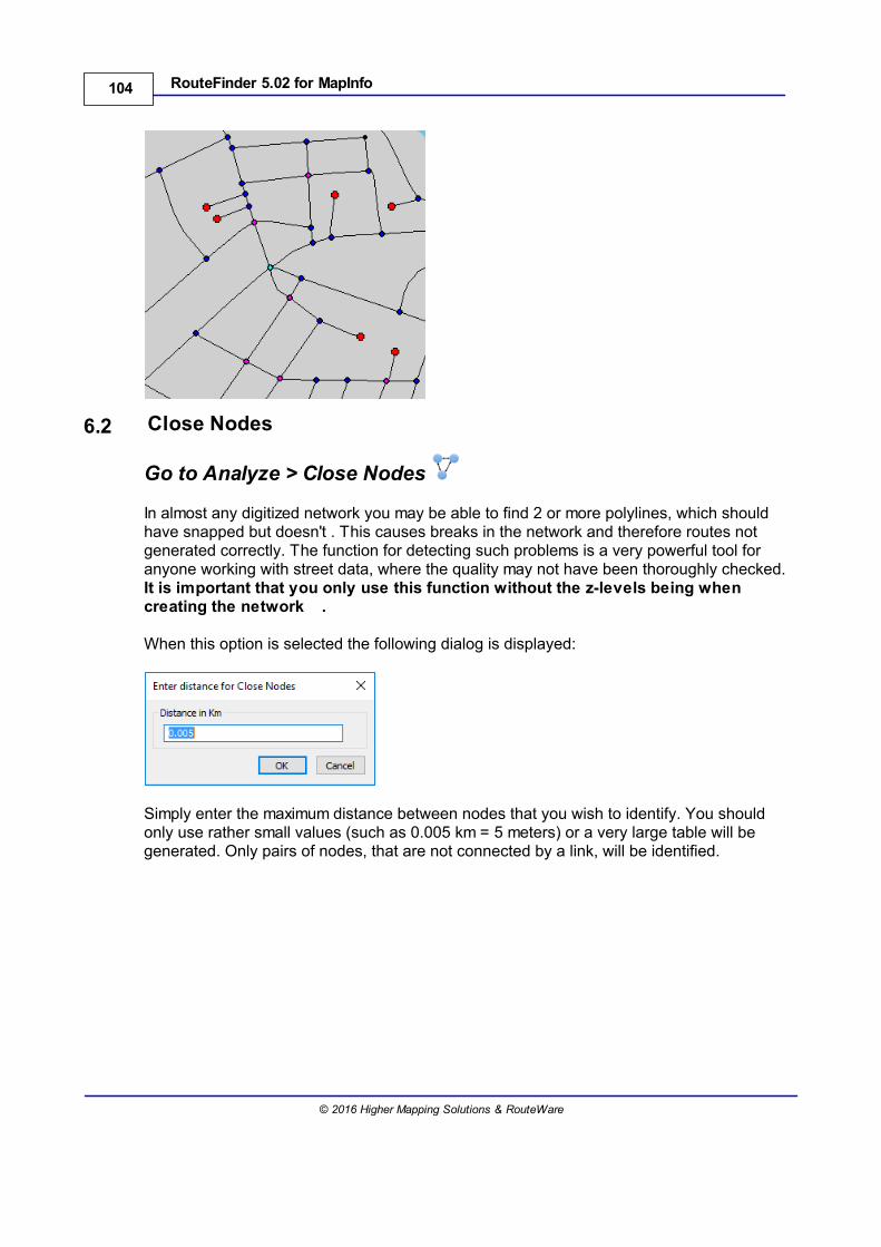
104 RouteFinder 5.02 for MapInfo
© 2016 Higher Mapping Solutions & RouteWare
6.2 Close Nodes
Go to Analyze > Close Nodes
In almost any digitized network you may be able to find 2 or more polylines, which shouldhave snapped but doesn't . This causes breaks in the network and therefore routes notgenerated correctly. The function for detecting such problems is a very powerful tool foranyone working with street data, where the quality may not have been thoroughly checked. It is important that you only use this function without the z-levels being when creating the network .
When this option is selected the following dialog is displayed:
Simply enter the maximum distance between nodes that you wish to identify. You shouldonly use rather small values (such as 0.005 km = 5 meters) or a very large table will begenerated. Only pairs of nodes, that are not connected by a link, will be identified.
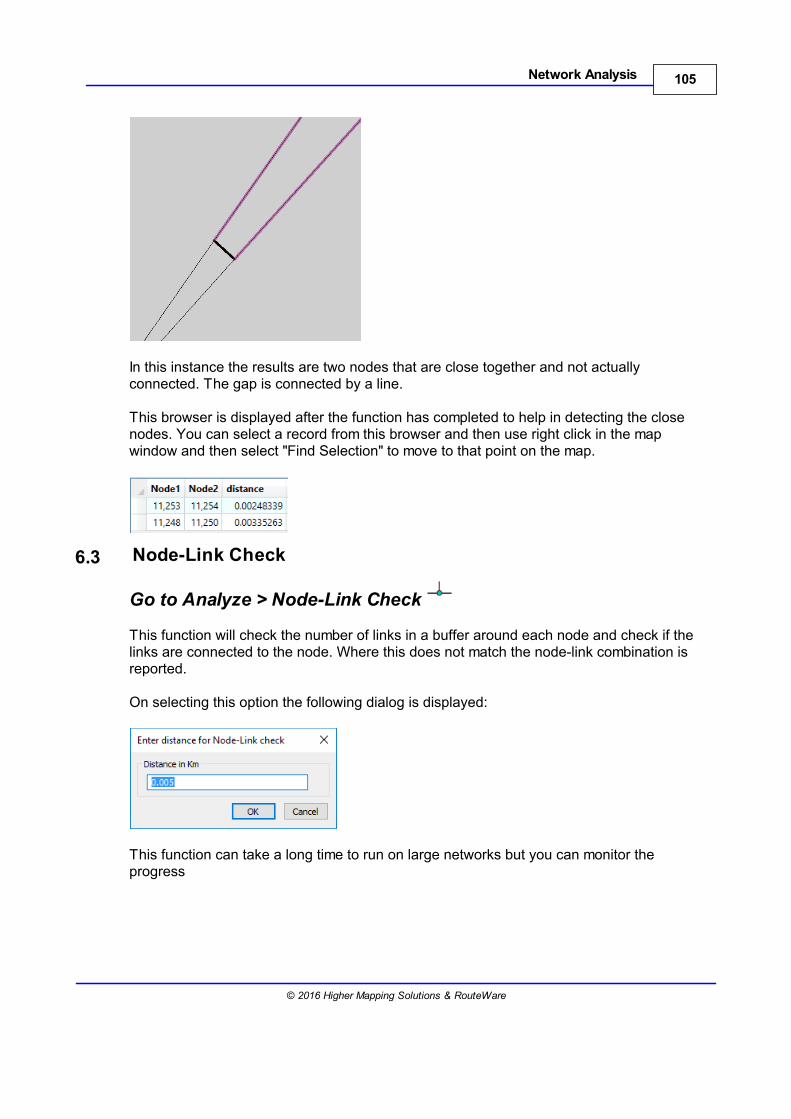
105Network Analysis
© 2016 Higher Mapping Solutions & RouteWare
In this instance the results are two nodes that are close together and not actuallyconnected. The gap is connected by a line.
This browser is displayed after the function has completed to help in detecting the closenodes. You can select a record from this browser and then use right click in the mapwindow and then select "Find Selection" to move to that point on the map.
6.3 Node-Link Check
Go to Analyze > Node-Link Check
This function will check the number of links in a buffer around each node and check if thelinks are connected to the node. Where this does not match the node-link combination isreported.
On selecting this option the following dialog is displayed:
This function can take a long time to run on large networks but you can monitor theprogress
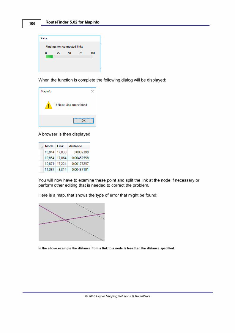
106 RouteFinder 5.02 for MapInfo
© 2016 Higher Mapping Solutions & RouteWare
When the function is complete the following dialog will be displayed:
A browser is then displayed
You will now have to examine these point and split the link at the node if necessary orperform other editing that is needed to correct the problem.
Here is a map, that shows the type of error that might be found:
In the above example the distance from a link to a node is less than the distance specified
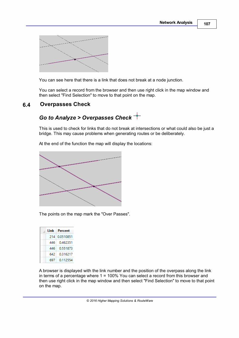
107Network Analysis
© 2016 Higher Mapping Solutions & RouteWare
You can see here that there is a link that does not break at a node junction.
You can select a record from the browser and then use right click in the map window andthen select "Find Selection" to move to that point on the map.
6.4 Overpasses Check
Go to Analyze > Overpasses Check
This is used to check for links that do not break at intersections or what could also be just abridge. This may cause problems when generating routes or be deliberately.
At the end of the function the map will display the locations:
The points on the map mark the "Over Passes".
A browser is displayed with the link number and the position of the overpass along the linkin terms of a percentage where 1 = 100% You can select a record from this browser andthen use right click in the map window and then select "Find Selection" to move to that pointon the map.
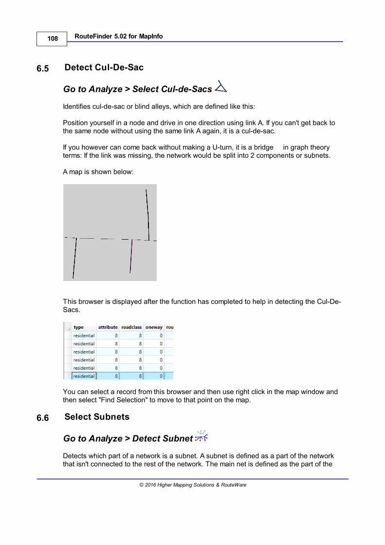
108 RouteFinder 5.02 for MapInfo
© 2016 Higher Mapping Solutions & RouteWare
6.5 Detect Cul-De-Sac
Go to Analyze > Select Cul-de-Sacs
Identifies cul-de-sac or blind alleys, which are defined like this:
Position yourself in a node and drive in one direction using link A. If you can't get back tothe same node without using the same link A again, it is a cul-de-sac.
If you however can come back without making a U-turn, it is a bridge in graph theoryterms: If the link was missing, the network would be split into 2 components or subnets.
A map is shown below:
This browser is displayed after the function has completed to help in detecting the Cul-De-Sacs.
You can select a record from this browser and then use right click in the map window andthen select "Find Selection" to move to that point on the map.
6.6 Select Subnets
Go to Analyze > Detect Subnet
Detects which part of a network is a subnet. A subnet is defined as a part of the networkthat isn't connected to the rest of the network. The main net is defined as the part of the
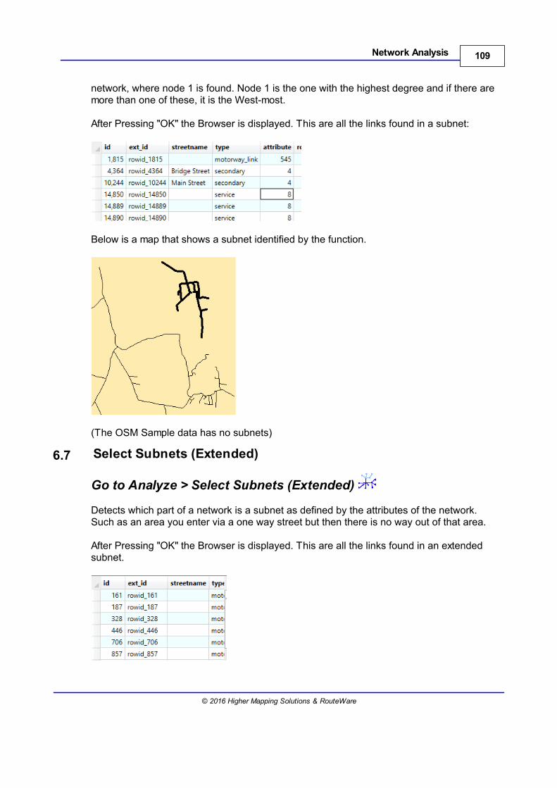
109Network Analysis
© 2016 Higher Mapping Solutions & RouteWare
network, where node 1 is found. Node 1 is the one with the highest degree and if there aremore than one of these, it is the West-most.
After Pressing "OK" the Browser is displayed. This are all the links found in a subnet:
Below is a map that shows a subnet identified by the function.
(The OSM Sample data has no subnets)
6.7 Select Subnets (Extended)
Go to Analyze > Select Subnets (Extended)
Detects which part of a network is a subnet as defined by the attributes of the network.Such as an area you enter via a one way street but then there is no way out of that area.
After Pressing "OK" the Browser is displayed. This are all the links found in an extendedsubnet.
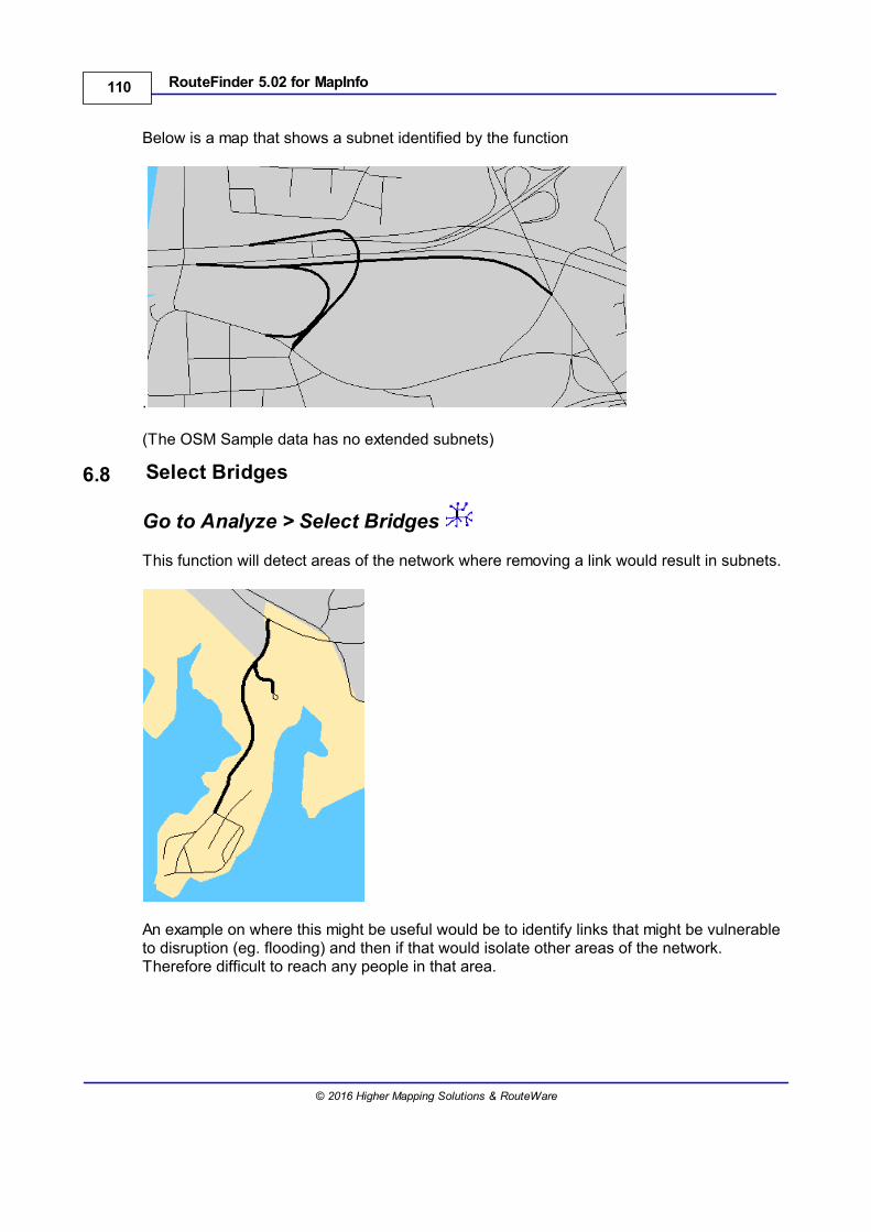
110 RouteFinder 5.02 for MapInfo
© 2016 Higher Mapping Solutions & RouteWare
Below is a map that shows a subnet identified by the function
.
(The OSM Sample data has no extended subnets)
6.8 Select Bridges
Go to Analyze > Select Bridges
This function will detect areas of the network where removing a link would result in subnets.
An example on where this might be useful would be to identify links that might be vulnerableto disruption (eg. flooding) and then if that would isolate other areas of the network.Therefore difficult to reach any people in that area.