Embed Size (px)
Citation preview

Route Classification and Signing System I-1
Appendix I
Route Classification and Signing System
The military route classification system helpsi n p l a n n i n g a n d e x e c ut i n g b a t t l e f i e l dmovements. Military engineers develop routeclassifications using a route classificationformula. This formula consists of a series ofnumbers and letters that express, in standardsequence, the route width, the route type, thelowest MLC, overhead clearance, obstructionsto the traffic flow, and special conditions on agiven route. Findings are based on informationextracted from route reconnaissance reports.
OVERVIEW
I-1. The first step in completing a route reconnaissanceoverlay is to understand what information must beincluded on it. As a minimum, include the followinginformation on the overlay:
• The route classification formula.• The name, rank, and social security number of
the person preparing the overlay.• The unit conducting the reconnaissance.• The DTG that the overlay was conducted.• The map name, edition, and scale.• Any remarks necessary to ensure the complete
understanding of the information contained onthe overlay.
I-2. This appendix focuses on the route classificationsystem and the methods necessary to determine theclassification of a road. Refer to FM 5-170 for more

I-2 Route Classification and Signing System
FM 3-19.4
in fo rm a ti o n ab o ut r o ut e c la s s i f i c a t i o n an dreconnaissance.
ROUTE CLASSIFICATION FORMULA
I-3. The route classification is derived from theinformation gathered during the route reconnaissance.The formula is recorded on the route reconnaissanceoverlay (Figure I-1) and consists of the following:
• The route width (in meters).• The route type (based on the ability to withstand
weather).• The lowest MLC.• The lowest overhead clearance (in meters).• Any obstructions (OB) to traffic flow, if
applicable.• Any special conditions, such as snow blockage
(T) or flooding (W).
I-4. The following are examples of route classificationformulas:
• 6.1/Z/40/ . A fair-weather route (Z) with aminimum traveled way of 6.1 meters and anMLC of 40. Overhead clearance is unlimited( ), and there are no obstructions to traffic flow.This route accommodates both wheeled andtracked, single-flow traffic without obstruction.
• 7/Y/50/4.6 (OB) (W). A limited, all-weather route(Y) with a minimum traveled way of 7 meters, anMLC of 50, an overhead clearance of 4.6 meters,and an obstruction. This route width is notsuitable for double-flow traffic (wheeled ortracked). This route is subject to regular,recurrent flooding.
∞
∞

FM 3-19.4
Route Classification and Signing System I-3
I-5. Table I-1, page I-4, gives route reconnaissancesymbols used on a route reconnaissance overlay.
Figure I-1. Route Reconnaissance Overlay
Name, RankSSNUnitDTGMap NameEditionScaleRemarks:

I-4 Route Classification and Signing System
FM 3-19.4
Table I-1. Route Reconnaissance Symbols
Explanation Symbol Remarks
1. Abbreviatedbridge symbol
Use this symbol only when the mapscale does not permit the use of the fullNATO bridge symbol. If this symbol isused, submit DA Form 1249. Draw anarrow to the map location of the bridge.Show the bridge's serial number in thelower portion of the symbol and theMLC for single-flow traffic in the upperportion. If there are separate loadclassifications for tracked or wheeledvehicles, show the lesser classification.Underline the classification number ifthe width or overhead clearance isbelow the minimum standard.
2. Axial route Use a solid line and identify the route byan odd number.
3. Bypassdifficult
Use this symbol when the obstacle canbe crossed in the immediate vicinity, butsome work is necessary to improve thebypass.
4. Bypasseasy
Use this symbol when the obstacle canbe crossed in the immediate vicinity bya US 2 1/2-ton truck (or NATOequivalent) without work to improve thebypass.
5. Bypassimpossible
Use this symbol when the obstacle canbe crossed only by repairing orconstructing a feature or by detouringaround the obstacle.
6. Civil ormilitary routedesignation
Write the designation in parenthesesalong the route.
80
4
57
(B209)

FM 3-19.4
Route Classification and Signing System I-5
7.Concealment Show roads lined with trees by a singleline of circles for deciduous trees and asingle line of inverted Vs for evergreentrees. Show woods bordering a road byseveral rows of circles for deciduoustrees and several rows of inverted Vsfor evergreen trees.
8. Criticalpoints
Number, in order, and describe criticalpoints on DA Form 1711-R. Use criticalpoints to show the features notadequately covered by other symbolson an overlay.
9. Damage ordestruction
Damage or destruction that preventsmovement along the route.
10. FerryFerry typeP–pedestrian
V–vehicular
Draw an arrow to the ferry location. Thedata above the symbols shows, in order,the left approach, the ferry's serialnumber, the ferry type, and rightapproach. The data inside the symbolshows, from left to right, the MLC andthe dead weight capacity in tons. Thenumber below the symbol shows theturnaround time, in minutes. A questionmark indicates unknown information.Show the different approaches by azigzag line, and show easy approachesby a straight line.
Table I-1. Route Reconnaissance Symbols (Continued)
Explanation Symbol Remarks
3
2 P
6?
12
4 V?60
20
I-6 Route Classification and Signing System
FM 3-19.4
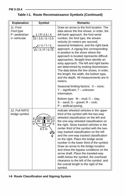
11. FordFord typeP–pedestrianV–vehicular
Draw an arrow to the ford location. Thedata above the line shows, in order, theleft-bank approach, the ford serialnumber, the ford type, the streamvelocity (in meters per second),seasonal limitations, and the right-bankapproach. A zigzag line correspondingin position to the shore where theapproach is located represents difficultapproaches. Straight lines identify aneasy approach. The left and right banksare determined by looking downstream.The data below the line shows, in order,the length, the width, the bottom type,and the depth. All measurements are inmeters.
Seasonal limiting factors: X – none;Y – significant; ? – unknowninformation.
Bottom type: M – mud; C – clay,S – sand; G – gravel; R – rock;P – artificial paving.
12. Full NATObridge symbol
Indicate wheeled vehicles in the upperthird of the symbol with the two-waywheeled classification on the left andthe one-way wheeled classification onthe right. Show tracked vehicles in thecenter third of the symbol with the two-way tracked classification on the leftand the one-way tracked classificationon the right. Place the bridge serialnumber in the lower third of the symbol.Draw an arrow to the bridge locationand show the bypass conditions on thearrow shaft. Place the traveled-waywidth below the symbol, the overheadclearance to the left of the symbol, andthe overall length to the right of thesymbol.
Table I-1. Route Reconnaissance Symbols (Continued)
Explanation Symbol Remarks
1 / P/ 2.5 / X15 / 3.5 / S / 0.5
4 / V / ? / Y15 / 3 / P / 0.75
100 10060 90
B38.2 m
4.5
m
13.5m

FM 3-19.4
Route Classification and Signing System I-7
13. Grades Show the actual percent of grade to theright of the symbol. Any grade of 7percent or more is an obstruction.Include the obstruction in the routeclassification formula. Arrows shouldpoint uphill. The length of the arrowrepresents the length of the grade if themap scale permits.
14. Lateralroute
Use a broken line, and identify the routeby an even number.
15. Limits ofsector
Show the beginning and ending of areconnoitered section of a route or roadwith this symbol.
16. MSR Label the route as MSR and assign acode name.
17. Obstaclea. Proposedblock
b. Preparedbut passable
c. Completedblock
Place the center of the symbol over thelocation of the blocked part of the route.Use parallel broken lines for a proposedblock, parallel lines for a prepared butpassable block, and crossed lines for acompleted block.
18. Clearanceunlimited
Use this symbol when overheadclearance is unlimited.
19. Parkingarea
Designate parking areas.
20. Railroadcrossing
Use this symbol to show a levelcrossing where passing trains wouldinterrupt the traffic flow. If there is apower line present, show its height, inmeters, from the ground. Underline theoverhead clearance if it is less than 4.3meters.
Table I-1. Route Reconnaissance Symbols (Continued)
Explanation Symbol Remarks
5 9 11 17
5-7%
7-10
%
10-1
4%
Ov e
r1 4
%
32
MSR DOG
a.
b.
c.
4.1 m
I-8 Route Classification and Signing System
FM 3-19.4
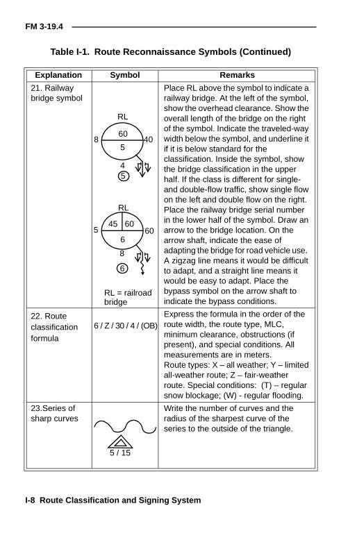
21. Railwaybridge symbol
Place RL above the symbol to indicate arailway bridge. At the left of the symbol,show the overhead clearance. Show theoverall length of the bridge on the rightof the symbol. Indicate the traveled-waywidth below the symbol, and underline itif it is below standard for theclassification. Inside the symbol, showthe bridge classification in the upperhalf. If the class is different for single-and double-flow traffic, show single flowon the left and double flow on the right.Place the railway bridge serial numberin the lower half of the symbol. Draw anarrow to the bridge location. On thearrow shaft, indicate the ease ofadapting the bridge for road vehicle use.A zigzag line means it would be difficultto adapt, and a straight line means itwould be easy to adapt. Place thebypass symbol on the arrow shaft toindicate the bypass conditions.
22. Routeclassificationformula
Express the formula in the order of theroute width, the route type, MLC,minimum clearance, obstructions (ifpresent), and special conditions. Allmeasurements are in meters.Route types: X – all weather; Y – limitedall-weather route; Z – fair-weatherroute. Special conditions: (T) – regularsnow blockage; (W) - regular flooding.
23.Series ofsharp curves
Write the number of curves and theradius of the sharpest curve of theseries to the outside of the triangle.
Table I-1. Route Reconnaissance Symbols (Continued)
Explanation Symbol Remarks
45
4060
58
RL
8
6
6
45 60
RL
605
6 / Z / 30 / 4 / (OB)
5 / 15
RL = railroadbridge
FM 3-19.4
Route Classification and Signing System I-9
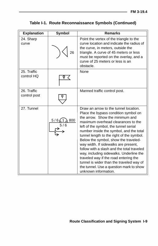
24. Sharpcurve
Point the vertex of the triangle to thecurve location and indicate the radius ofthe curve, in meters, outside thetriangle. A curve of 45 meters or lessmust be reported on the overlay, and acurve of 25 meters or less is anobstacle.
25. Trafficcontrol HQ
None
26. Trafficcontrol post
Manned traffic control post.
27. Tunnel Draw an arrow to the tunnel location.Place the bypass condition symbol onthe arrow. Show the minimum andmaximum overhead clearances to theleft of the symbol, the tunnel serialnumber inside the symbol, and the totaltunnel length to the right of the symbol.Below the symbol, show the traveled-way width. If sidewalks are present,follow with a slash and the total traveledway, including sidewalks. Underline thetraveled way if the road entering thetunnel is wider than the traveled way ofthe tunnel. Use a question mark to showunknown information.
Table I-1. Route Reconnaissance Symbols (Continued)
Explanation Symbol Remarks
26
5 / 6 1 8005 / 6
I-10 Route Classification and Signing System
FM 3-19.4
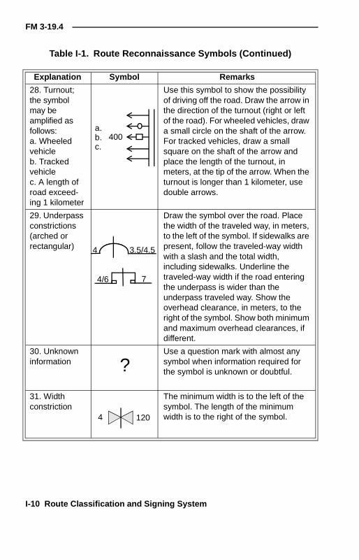
28. Turnout;the symbolmay beamplified asfollows:a. Wheeledvehicleb. Trackedvehiclec. A length ofroad exceed-ing 1 kilometer
Use this symbol to show the possibilityof driving off the road. Draw the arrow inthe direction of the turnout (right or leftof the road). For wheeled vehicles, drawa small circle on the shaft of the arrow.For tracked vehicles, draw a smallsquare on the shaft of the arrow andplace the length of the turnout, inmeters, at the tip of the arrow. When theturnout is longer than 1 kilometer, usedouble arrows.
29. Underpassconstrictions(arched orrectangular)
Draw the symbol over the road. Placethe width of the traveled way, in meters,to the left of the symbol. If sidewalks arepresent, follow the traveled-way widthwith a slash and the total width,including sidewalks. Underline thetraveled-way width if the road enteringthe underpass is wider than theunderpass traveled way. Show theoverhead clearance, in meters, to theright of the symbol. Show both minimumand maximum overhead clearances, ifdifferent.
30. Unknowninformation
Use a question mark with almost anysymbol when information required forthe symbol is unknown or doubtful.
31. Widthconstriction
The minimum width is to the left of thesymbol. The length of the minimumwidth is to the right of the symbol.
Table I-1. Route Reconnaissance Symbols (Continued)
Explanation Symbol Remarks
a.b.c.
400
4/6
3.5/4.5
7
4
?
4 120
FM 3-19.4
Route Classification and Signing System I-11
ROUTE WIDTHS
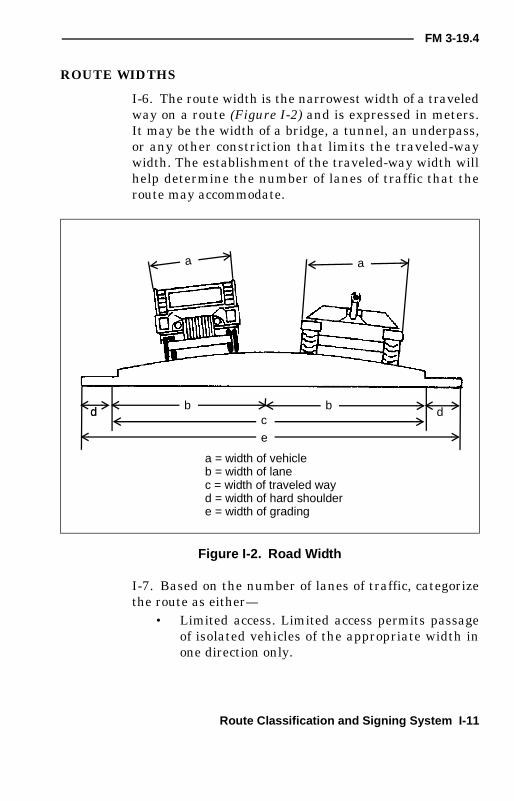
I-6. The route width is the narrowest width of a traveledway on a route (Figure I-2) and is expressed in meters.It may be the width of a bridge, a tunnel, an underpass,or any other constriction that limits the traveled-waywidth. The establishment of the traveled-way width willhelp determine the number of lanes of traffic that theroute may accommodate.
I-7. Based on the number of lanes of traffic, categorizethe route as either—
• Limited access. Limited access permits passageof isolated vehicles of the appropriate width inone direction only.
Figure I-2. Road Width
a = width of vehicleb = width of lanec = width of traveled wayd = width of hard shouldere = width of grading
d db bc
e
d
a a
I-12 Route Classification and Signing System
FM 3-19.4
• Single lane. A single lane permits use in onlyone direction at any one time. Passing ormo ve ment i n t h e o ppos i t e d i rec t i o n isimpossible.
• Single flow. Single flow permits the passage of acolumn of vehicles and allows isolated vehicles topass or travel in the opposite direction atpredetermined points only.
• Double flow. Double flow permits two columns ofvehicles to proceed simultaneously.
ROUTE TYPES
I-8. Route types are designated by their ability towithstand the effects of weather, and are determined bythe worst section of the route. The three types of routesare—
• Type X. Type X is an all-weather route that, withreasonable maintenance, is passable throughoutthe year to its maximum volume of traffic. Thistype of route is normally formed of roads havingwaterproof surfaces, is only minimally affectedby precipitation or temperature changes, and isnever closed from the effects of weather.
• Type Y. Type Y is a limited, all-weather routethat, with reasonable maintenance, is passablethroughout the year, but at times having avolume of traf f ic considerably less thanmaximum capacity. This type of route isnormally formed of roads that do not havewaterproof surfaces and are affected by weatheror temperature changes. This type of route isclosed for short periods (up to one day at a time)by adverse weather conditions during whichheavy use of the road would probably lead tocomplete collapse.
• Type Z. Type Z is a fair-weather route that maybecome impassable in adverse weather. It may
FM 3-19.4
Route Classification and Signing System I-13
be closed for long periods, and may requiremajor maintenance or construction efforts toreopen it.
MILITARY LOAD CLASSIFICATION
I-9. A route MLC is a class number representing thesafe load-carrying capacity and indicating the maximumvehicle class that can be accepted under normalconditions. Usually, the lowest bridge MLC (regardlessof the vehicle type or conditions of traffic flow)determines the route MLC. If there is not a bridge on theroute, the worst section of road determines the routeoverall classification.
I-10. Whenever possible, the basic military roadnetwork is composed of average routes and includes anumber of heavy traffic routes and a few very heavytraffic routes. Individual routes are grouped andidentified in broad categories, such as—
• Average traffic routes are Class 50.• Heavy traffic routes are Class 80.• Very heavy traffic routes are Class 120.
OVERHEAD CLEARANCE
I-11. Overhead clearance is the vertical distancebetween the road's surface and any overhead obstacle(power lines, overpasses, tunnels, and so forth) thatdenies the use of the route or road to all vehicles or loadsthat exceed this height. This distance is represented inthe route classification formula, in meters. Use theinfinity symbol ( ) in the formula for unlimitedoverhead clearance. Any point along the route where theminimum overhead clearance is less than 4.3 meters isconsidered an obstruction.
∞
I-14 Route Classification and Signing System
FM 3-19.4
ROUTE OBSTRUCTIONS
I-12. Route obstructions are conditions that restrict thetype, amount, or speed of the traffic flow. They areindicated in the route classification formula as OB. If anobstruction is encountered and reported, depict its exactnature on the route classification overlay. Reportableobstructions include the following:
• Overhead obstructions, such as tunnels,underpasses, power lines, and so forth, with aclearance of less than 4.3 meters.
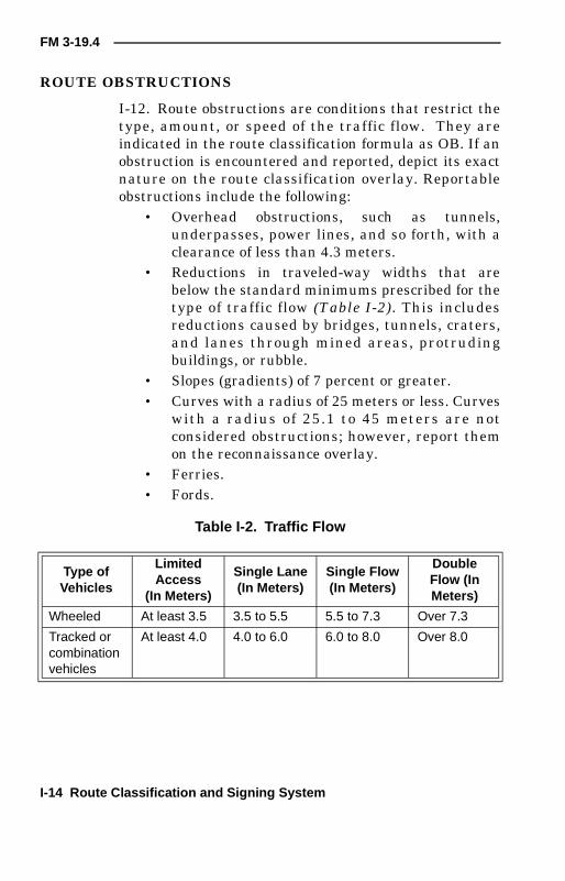
• Reductions in traveled-way widths that arebelow the standard minimums prescribed for thetype of traffic flow (Table I-2). This includesreductions caused by bridges, tunnels, craters,and lanes through mined areas, protrudingbuildings, or rubble.
• Slopes (gradients) of 7 percent or greater.• Curves with a radius of 25 meters or less. Curves
with a radius of 25.1 to 45 meters are notconsidered obstructions; however, report themon the reconnaissance overlay.
• Ferries.• Fords.
Table I-2. Traffic Flow
Type ofVehicles
LimitedAccess
(In Meters)
Single Lane(In Meters)
Single Flow(In Meters)
DoubleFlow (InMeters)
Wheeled At least 3.5 3.5 to 5.5 5.5 to 7.3 Over 7.3
Tracked orcombinationvehicles
At least 4.0 4.0 to 6.0 6.0 to 8.0 Over 8.0

FM 3-19.4
Route Classification and Signing System I-15
SPECIAL CONDITIONS (SNOW BLOCKAGE ANDFLOODING)
I-13. Conditions, such as snow and water, are notnormally classified as obstructions, except where theseconditions are regular, recurrent, and serious. In caseswhere snow accumulation is excessive and is eitherblocking traffic or has the potential to block traffic, thesymbol following the route classification formula is T.Similarly, where flooding poses the same problem, thesymbol following the formula is W.
CALCULATIONS
I-14. Make calculations for the various curves, slopes,and fords that may affect vehicle movement along theroute.
CURVES
I-15. The speeds that vehicles move along the route andsecurity planning measures are affected by sharp curvesin the roadway. As previously stated, curves with aradius of 25 meters and less are obstructions to trafficand are indicated by OB in the route classificationformula and identified on DA Form 1248. There areseveral ways to measure the radius of a curve, but thetwo easiest are the tape measure and formula methods.
Tape Measure Method
I-16. The quickest way to estimate the radius of a sharpcurve is by using a tape measure to find the radius(Figure I-3, page I-16). Imagine the outer edge of thecurve as the outer edge of a circle. Find (estimate) thecenter of this imaginary circle; then measure the radiususing a tape measure. Start from the center of the circleand measure to the outside edge of the curve. The lengthof the tape measure from the center of the imaginarycircle to its outer edge is the curve radius. This method

I-16 Route Classification and Signing System
FM 3-19.4
is practical for curves having a radius up to 15 metersand located on relatively flat ground.
Formula Method
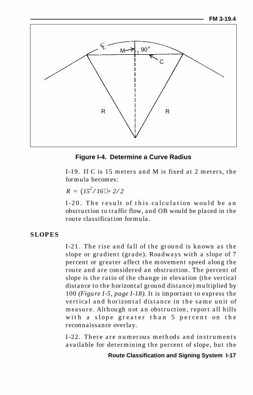
I-17. The other, and often more practical, method ofdetermining a curve radius (Figure I-4) is based on thefollowing formula:
where—
R = radius of the curve
C = distance from the centerline of the road to thecenterline of the road at the outer extremities (beginningand end) of the curve
M = perpendicular distance from the center of the tape tothe centerline of the road
I-18. When conditions warrant, set M at 2 meters fromthe centerline, then measure C at 2 meters from thecenterline. Use this method when there is a timelimitation or because natural or man-made restrictionsprevent proper measurements.
Figure I-3. Find the Radius with a Tape Measure
PC
PT
Tape
RoadCL
R C2
8m⁄( )+ M 2⁄( )=
FM 3-19.4
Route Classification and Signing System I-17
I-19. If C is 15 meters and M is fixed at 2 meters, theformula becomes:
I-20. The result of this calculation would be anobstruction to traffic flow, and OB would be placed in theroute classification formula.
SLOPES
I-21. The rise and fall of the ground is known as theslope or gradient (grade). Roadways with a slope of 7percent or greater affect the movement speed along theroute and are considered an obstruction. The percent ofslope is the ratio of the change in elevation (the verticaldistance to the horizontal ground distance) multiplied by100 (Figure I-5, page I-18). It is important to express thevertical and horizontal distance in the same unit ofmeasure. Although not an obstruction, report all hillsw i t h a s l o p e g r e a te r t h a n 5 p e r c e n t o n t h ereconnaissance overlay.
I-22. There are numerous methods and instrumentsavailable for determining the percent of slope, but the
Figure I-4. Determine a Curve Radius
R R
C
90M °CL
R 152
16⁄( ) 2 2⁄+=

I-18 Route Classification and Signing System
FM 3-19.4
two hasty and most practical methods are the map andpace methods.
Map Method
I-23. Use a large-scale map (such as 1:50,000) toestimate the percent of slope quickly. After identifyingthe slope on the map, find the difference in elevationsbetween the top and bottom of the slope by reading theelevation contours or spot elevation. Then, measure andconvert the horizontal distance (usually road distance)to the same unit of measurement as the elevationdifference. Substitute the vertical and horizontaldistances in the percent-of-slope formula and computethe percent of slope (Figure I-6). This is a hasty methodand is the less accurate of the two methods.
Pace Method
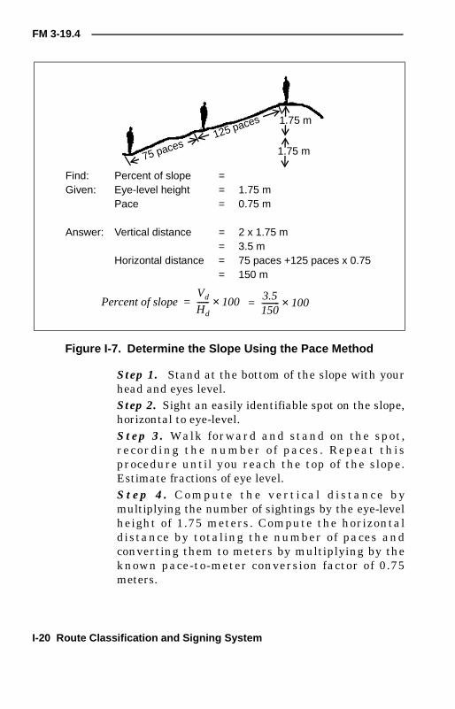
I-24. The pace method is another quick way to estimatethe percent of slope. Before using this method, accu-rately determine the height and pace of each member ofthe reconnaissance team. As a general rule of thumb,the eye level of the average soldier is 1.75 meters abovethe ground (Figure I-7, page I-20). The pace of the aver-age soldier is 0.75 meters. Perform the following steps todetermine the percentage of slopes:
Figure I-5. Calculate the Percent of Slope
Slope
A
B
1,000 mHorizontal distance (Hd)
100 mvertical
distance(Vd)
Percent of slopeVd
Hd------ 100×=
100 m1 000 m,--------------------- 100×=
+10 percent=

FM 3-19.4
Route Classification and Signing System I-19
Figure I-6. Determine the Slope with a Map
193B
180150
140
120100A
0 m 1,000 m 2,000 m 3,000 m 4,000 m 5,000 m
Find the difference in elevation (Vd)
Spot elevation B = 193 m
Spot elevation A = 100 m
Difference in elevation (Vd) = 93 m
Find the horizontal distance (Hd)
Road distance A to B (use a piece of paper and a graphicscale as shown in FM 21-26) = 3,720 m
Use the percent-of-slope formula.
933 720,--------------- 100×=
+ 2.5 percent
Vd
Hd------ 100×
I-20 Route Classification and Signing System
FM 3-19.4
Step 1. Stand at the bottom of the slope with yourhead and eyes level.Step 2. Sight an easily identifiable spot on the slope,horizontal to eye-level.Step 3. Walk forward and stand on the spot,recording the number of paces . Repeat thisprocedure until you reach the top of the slope.Estimate fractions of eye level.St ep 4. C o mpu te th e v e rt i ca l d i s ta nc e b ymultiplying the number of sightings by the eye-levelheight of 1.75 meters. Compute the horizontaldistance by totaling the number of paces andconverting them to meters by multiplying by theknown pace-to-meter conversion factor of 0.75meters.
Figure I-7. Determine the Slope Using the Pace Method
75 paces125 paces
1.75 m
1.75 m
Find: Percent of slope =Given: Eye-level height = 1.75 m
Pace = 0.75 m
Answer: Vertical distance = 2 x 1.75 m= 3.5 m
Horizontal distance = 75 paces +125 paces x 0.75= 150 m
Percent of slopeVd
Hd------ 100×= 3.5
150--------- 100×=
FM 3-19.4
Route Classification and Signing System I-21
St ep 5. C a lc ul at e t he p e rc e nt o f s l o pe b ysubstituting the values into the percent-of-slopeformula (Figure I-7). Because this method considershorizontal ground distance and incline distance asequal, the reasonable accuracy is only for slopes lessthan 30 percent. This method requires repeatedpractice to achieve reasonable accuracy.
FORDS
I-25. A ford is a location in a water barrier where thecurrent, bottom, and approaches allow personnel andvehicles to cross and remain in contact with the bottomduring the crossing. While engineers are fully trainedand equipped in this area, MP are also capable ofper forming this task. In the co urse of a routereconnaissance, MP identify potential fording sites as acontingency for bridges that may become unusable.When identifying a ford on the reconnaissance overlay,include the following information in the ford symbol:
• The ford location, as indicated by an arrow fromthe ford symbol to the site on the overlay.
• A serial number assigned to each ford forreference. Follow the unit SOP in assigningserial numbers, ensuring that the same numberis not duplicated on any one overlay.
• The type of ford, as determined by bottomcomposition, width, and water depth. Use V forvehicle, P for pedestrian, or VP for both.Approaches are not considered in determiningthe ford type.
• The stream’s normal current velocity isexpressed in meters per second. Seasonallimiting factors follow the stream velocitynotation and are shown by the following letters:■ X - No seasonal limitations except for
potential sudden flooding of limited duration(flash flooding).
■ Y - Serious, regular, or recurrent flooding orsnow blockage.
I-22 Route Classification and Signing System
FM 3-19.4
NOTE: If the Y symbol is used, the route type in the routeclassification formula automatically becomes type Z.
• The length of the ford (distance from nearshoreto far shore), in meters.
• The nature of the bottom surface, using the mostappropriate letter symbol—■ M – mud.■ C – clay.■ S – sand.■ G – gravel.■ R – rock.■ P – artificial paving.
• The normal stream depth at its deepest point,expressed in meters.
I-26. Separate all elements of the ford symbol byslashes. Substitute a question mark for any item ofinformation that is unknown. Record all the informationon the route reconnaissance overlay.
Stream Width
I-27. There are many method s of d etermining(estimating) the stream’s width. The most common andpractical is the compass method. Begin by using acompass to take an azimuth from a point on thenearshore and close to the water’s edge to a point on theopposite shore and close to the water’s edge (Figure I-8).On the nearshore, establish another point that is on aline and at a right angle to the azimuth selected. Theazimuth to the same point on the far shore is plus orminus 45 degrees (800 mils) from the previous azimuth.Measure the distance between the two points on thenearshore. This distance is equal to the distance acrossthe stream.
Current Velocity
I-28. Current velocities vary in different parts of astream. Velocity is usually slower near the shore and

FM 3-19.4
Route Classification and Signing System I-23
faster in the main channel of the stream. To estimatestream velocity—
• Measure a distance along the nearshore.• Throw a light, floating object that will not be
affected by the wind into the stream.• Record the time that is takes for the object to
travel measured distance.• Repeat this procedure at least three times to
establish an accurate average.• Use the average time of the test in the following
formula (Figure I-9, page I-24) to determine thestream’s velocity.
Velocity (in meters per second) = measured distance (inmeters)/average time (in seconds)
TEMPORARY ROUTE SIGNING
I-29. A military route sign system, like the US highwaysign system, can enable road users to reach theirdestinations by following route signs and road markingsdisplayed along the roadside. MP patrols monitor signson a routine basis, checking specific signs before critical
Figure I-8. Determine Stream Width
A C
B Far shore
Nearshore
315
270
°°
A - Point on nearshoreB - Point on far shoreAB - Distance to be measuredAzimuth of line AB is 315 (movingleft, add 45 ; moving right, subtract45 ).Azimuth of line CB is 270 .Difference between azimuth AB andazimuth CB is 45 .Distance along AC equals distancealong AB.
°°
°
°
°°°°

I-24 Route Classification and Signing System
FM 3-19.4
moves. Engineers erect permanent signs, but these signscan be damaged, destroyed, or moved by weather,saboteurs, and battle.
I-30. When MP on patrol encounter immediate andtemporary MSR obstructions, like blown bridges or NBCcontamination, they construct and erect signs quickly toguide vehicles around the obstruction. Prepare and posttemporary signs to—
• Identify routes.• Reroute traffic around problem areas.
Figure I-9. Determine Stream Velocity
Direction of current
C A
A'
B
B'
VelocityA'B' (meters or feet)
Time to float from A to B (seconds)------------------------------------------------------------------------------------=
Measure distance A'B'.Throw a floating object into the stream at C.Determine the time required for the object to floatto distance from A to B.
NOTE: This should be done three times, withthe final velocity being the average of thethree.
FM 3-19.4
Route Classification and Signing System I-25
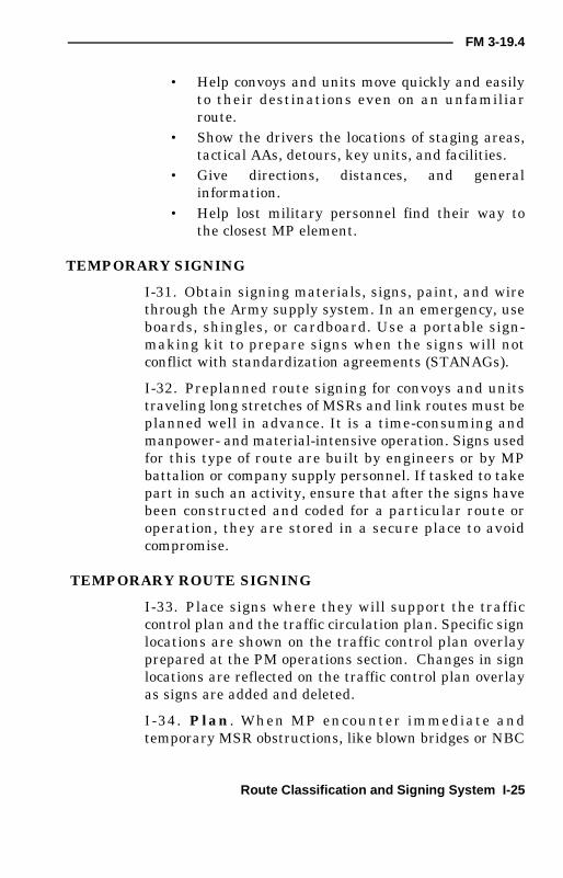
• Help convoys and units move quickly and easilyto their destinations even on an unfamiliarroute.
• Show the drivers the locations of staging areas,tactical AAs, detours, key units, and facilities.
• Give directions, distances, and generalinformation.
• Help lost military personnel find their way tothe closest MP element.
TEMPORARY SIGNING
I-31. Obtain signing materials, signs, paint, and wirethrough the Army supply system. In an emergency, useboards, shingles, or cardboard. Use a portable sign-making kit to prepare signs when the signs will notconflict with standardization agreements (STANAGs).
I-32. Preplanned route signing for convoys and unitstraveling long stretches of MSRs and link routes must beplanned well in advance. It is a time-consuming andmanpower- and material-intensive operation. Signs usedfor this type of route are built by engineers or by MPbattalion or company supply personnel. If tasked to takepart in such an activity, ensure that after the signs havebeen constructed and coded for a particular route oroperation, they are stored in a secure place to avoidcompromise.
TEMPORARY ROUTE SIGNING
I-33. Place signs where they will support the trafficcontrol plan and the traffic circulation plan. Specific signlocations are shown on the traffic control plan overlayprepared at the PM operations section. Changes in signlocations are reflected on the traffic control plan overlayas signs are added and deleted.
I-34. Plan . When MP encounter immediate andtemporary MSR obstructions, like blown bridges or NBC

I-26 Route Classification and Signing System
FM 3-19.4
contaminat io n, they use the squad route s ig nkit or construct and erect hasty signs quickly to guidev e h i c l e s ar o u n d th e o b s t r u ct i o n s . P l a n n i n gconsiderations include the following:
• Identifying routes.• Rerouting traffic around problem areas.• Helping convoys and units move quickly and
easily to their destinations, even on unfamiliarroutes.
• Showing drivers the locations of staging areas,tactical AAs, detours, key units, and facilities.
• Giving directions, distances, and generalinformation.
I-35. Execute. Place signs where they will support thetraffic control plan and the traffic circulation plan.Specific sign locations are shown on the traffic controlplan overlay. Changes in sign locations are reflected onthe traffic control plan overlay as signs are added ordeleted.
I-36. Often, one three-man team can place signs along aroute. To post a sign, a team member dismounts andwalks 50 to 100 meters up the road. The other teammembers provide security and check and confirm thesign's placement to ensure that the drivers will be ableto see the sign.
I-37. MP squads use the route signing kit to place signsalong a route within the squad's AO. One team posts thesigns while the other teams provide security. The squadleader checks and confirms the sign placement bytraveling the entire route. He develops an overlay withthe location of each sign in his squad’s AO. Squadoverlays are consolidated and contribute to a platoontraffic control plan.
I-38. More teams, up to a squad, may be needed forsigning tasks in urban areas, in areas where a thoroughreconnaissance has not been conducted, and in areas
FM 3-19.4
Route Classification and Signing System I-27
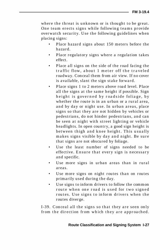
where the threat is unknown or is thought to be great.One team erects signs while following teams provideoverwatch security. Use the following guidelines whenplacing signs:
• Place hazard signs about 150 meters before thehazard.
• Place regulatory signs where a regulation takeseffect.
• Place all signs on the side of the road facing thetraffic flow, about 1 meter off the traveledroadway. Conceal them from air view. If no coveris available, slant the sign stake forward.
• Place signs 1 to 2 meters above road level. Placeall the signs at the same height if possible. Signheight is governed by roadside foliage, bywhether the route is in an urban or a rural area,and by day or night use. In urban areas, placesigns so that they are not hidden by vehicles orpedestrians, do not hinder pedestrians, and canbe seen at night with street lighting or vehicleheadlights. In open country, a good sign height isbetween thigh and knee height. This usuallymakes signs visible by day and night. Be surethat signs are not obscured by foliage.
• Use the least number of signs needed to beeffective. Ensure that every sign is necessaryand specific.
• Use more signs in urban areas than in ruralareas.
• Use more signs on night routes than on routesprimarily used during the day.
• Use signs to inform drivers to follow the commonroute when one road is used for two signedroutes. Use signs to inform drivers when theroutes diverge.
I-39. Conceal all the signs so that they are seen onlyfrom the direction from which they are approached.

I-28 Route Classification and Signing System
FM 3-19.4
There is no exact rule stating the distance from which asign should be visible. However, the distance should beno greater than security allows and not less than isreasonable for those receiving directions.
I-40. Carefully conceal illuminated signs. Ensure thatthe light source is just strong enough to light the sign,but not strong enough to be seen from the air. Thisentails masking and covering the light sources. Considerplacing chemical light sticks on top of the signs.
I-41. Place temporary route signs where they willprovide warning and reaction time for the drivers. Donot block existing civilian signs. Place warning panels atconvenient distances from where a route regulationtakes effect. This distance can be shown on the panel (forexample, BLACKOUT 500 METERS). In areas whereblackout drive is the rule and drivers are using night-vision equipment, employ IR emitters on signs alongroutes to help guide the units to their destination. Justlike any other light source, ensure that the IR emitterscannot be seen from the air.
I-42. Place guide signs at road junctions to preventconfusion. Put signs on both sides of the road if needed.Place confirmation signs (Table I-3) 150 meters beyond thecritical road junctions to let drivers know that they are onthe correct route.

FM 3-19.4
Route Classification and Signing System I-29
Tabl
eI-
3.S
igns
Iden
tifyi
ngM
ilita
ryR
oute
san
dLo
catio
ns
Type
Exa
mpl
esD
escr
iptio
nP
urpo
seP
lace
men
t
Dire
ctio
nin
dica
tor
Whi
te,3
0-ce
ntim
eter
diam
eter
disk
with
blac
kdi
rect
iona
larr
ow(I
Dnu
mbe
ror
nam
eis
mou
nted
belo
wth
edi
sk) or
Whi
tedi
skon
blac
kre
ctan
gula
rbo
ard
with
the
iden
tific
atio
nnu
mbe
rab
ove
Indi
cate
sth
edi
rect
ion
and
iden
tifie
sth
ero
ute
orth
ena
me
Ati
nter
sect
ions
whe
rero
ads
mer
gean
dw
here
rout
esse
para
te

I-30 Route Classification and Signing System
FM 3-19.4
Type
Exa
mpl
esD
escr
iptio
nP
urpo
seP
lace
men
t
Gui
desi
gns
(use
toge
ther
atim
port
ant
road
junc
-tio
ns)
Rec
tang
ular
with
the
sym
bols
inw
hite
onbl
ack
back
grou
nd;
incl
udes
dire
c-tio
nala
rrow
and
rout
enu
mbe
r,na
me,
and/
orsy
mbo
l
Indi
cate
sth
elo
ca-
tions
,dis
tanc
es,
dire
ctio
ns,a
ndro
utes
Whe
rene
eded
War
ning
sign
s(u
seto
geth
erat
impo
rtan
tro
adju
nc-
tions
)
Sam
eas
abov
eS
how
sth
eco
rrec
tdi
rect
ion
tota
keat
rout
eju
nctio
ns
Asu
ffici
entd
is-
tanc
e(5
0to
100
met
ers)
befo
rea
junc
tion
toal
low
driv
ers
tom
ake
the
turn
safe
ly(O
nro
ads
whe
resp
eed
isre
stric
ted,
plac
eth
esi
gns
25m
eter
sbe
fore
the
junc
tion.
)
Tabl
eI-
3.S
igns
Iden
tifyi
ngM
ilita
ryR
oute
san
dLo
catio
ns(C
ontin
ued)

FM 3-19.4
Route Classification and Signing System I-31
Type
Exa
mpl
esD
escr
iptio
nP
urpo
seP
lace
men
t
Con
fiden
cesi
gns
Sam
eas
abov
eR
eass
ures
the
driv
ers
that
they
are
still
onth
eco
rrec
trou
te(U
seth
emin
urba
nar
eas
toas
sure
driv
ers
that
they
are
follo
win
gth
eco
rrec
trou
te.U
seth
emon
long
stre
tche
sof
road
whe
reit
isun
nece
ssar
yto
use
war
ning
and
conf
irmat
ion
sign
sfo
ra
cons
ider
able
dist
ance
.)
Whe
rene
eded
Con
firm
atio
nsi
gns
Sam
eas
abov
eLe
tsdr
iver
skn
owth
atth
eyar
eon
the
corr
ectr
oute
afte
rch
angi
ngdi
rect
ion
Just
afte
rtu
rns,
butv
isib
lew
hile
mak
ing
the
turn
,if
poss
ible
Tabl
eI-
3.S
igns
Iden
tifyi
ngM
ilita
ryR
oute
san
dLo
catio
ns(C
ontin
ued)

I-32 Route Classification and Signing System
FM 3-19.4
Type
Exa
mpl
esD
escr
iptio
nP
urpo
seP
lace
men
t
Cou
ntdo
wn
sign
sS
ame
asab
ove
War
nsof
sign
ifica
ntlo
catio
ns,s
uch
asS
Ps,
RP
s,st
arts
and
ends
ofro
utes
,lin
kro
utes
,MS
Rju
nctio
ns,a
ndbl
acko
utar
eas—
anyt
hing
requ
iring
am
ajor
chan
geto
the
mov
emen
t
Ser
ies
ofth
ree
sign
sat
100-
met
erin
terv
als
befo
reth
ede
sign
ated
loca
tion
Reg
ulat
ory
sign
sM
ilita
ryeq
uiva
lent
ofci
vilia
nsi
gns
like
ST
OP
and
YIE
LD
Reg
ulat
esan
dco
ntro
lsth
etr
affic
ona
rout
e
Whe
rene
eded
(pos
ted
byen
gine
ers
and
cons
ider
edpe
rman
ent)
Tabl
eI-
3.S
igns
Iden
tifyi
ngM
ilita
ryR
oute
san
dLo
catio
ns(C
ontin
ued)
FM 3-19.4
Route Classification and Signing System I-33
Tabl
eI-
3.S
igns
Iden
tifyi
ngM
ilita
ryR
oute
san
dLo
catio
ns(C
ontin
ued)
Type
Exa
mpl
esD
escr
iptio
nP
urpo
seP
lace
men
t
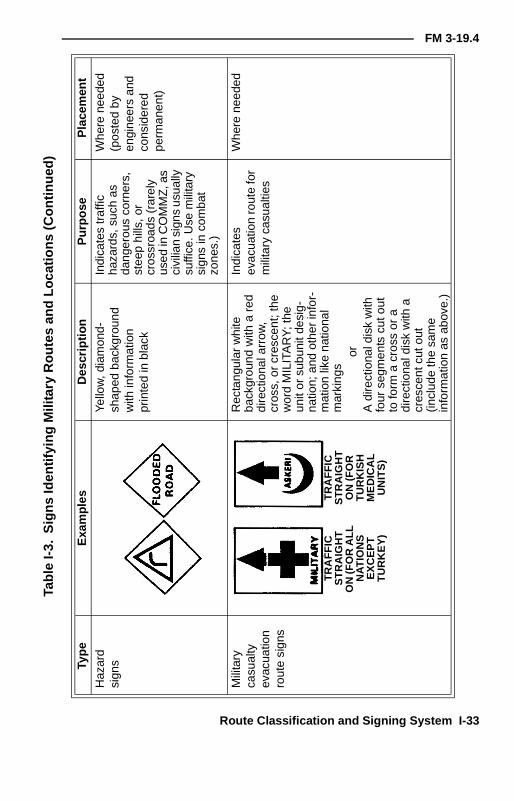
Haz
ard
sign
sYe
llow
,dia
mon
d-sh
aped
back
grou
ndw
ithin
form
atio
npr
inte
din
blac
k
Indi
cate
str
affic
haza
rds,
such
asda
nger
ous
corn
ers,
stee
phi
lls,o
rcr
ossr
oads
(rar
ely
used
inC
OM
MZ
,as
civi
lian
sign
sus
ually
suffi
ce.U
sem
ilita
rysi
gns
inco
mba
tzo
nes.
)
Whe
rene
eded
(pos
ted
byen
gine
ers
and
cons
ider
edpe
rman
ent)
Mili
tary
casu
alty
evac
uatio
nro
ute
sign
s
Rec
tang
ular
whi
teba
ckgr
ound
with
are
ddi
rect
iona
larr
ow,
cros
s,or
cres
cent
;the
wor
dM
ILIT
AR
Y;t
heun
itor
subu
nitd
esig
-na
tion;
and
othe
rin
for-
mat
ion
like
natio
nal
mar
king
sor
Adi
rect
iona
ldis
kw
ithfo
urse
gmen
tscu
tout
tofo
rma
cros
sor
adi
rect
iona
ldis
kw
itha
cres
cent
cuto
ut(in
clud
eth
esa
me
info
rmat
ion
asab
ove.
)
Indi
cate
sev
acua
tion
rout
efo
rm
ilita
ryca
sual
ties
Whe
rene
eded
TR
AF
FIC
ST
RA
IGH
TO
N(F
OR
ALL
NA
TIO
NS
EX
CE
PT
TU
RK
EY
)
TR
AF
FIC
ST
RA
IGH
TO
N(F
OR
TU
RK
ISH
ME
DIC
AL
UN
ITS
)

I-34 Route Classification and Signing System
FM 3-19.4
Tabl
eI-
3.S
igns
Iden
tifyi
ngM
ilita
ryR
oute
san
dLo
catio
ns(C
ontin
ued)
Type
Exa
mpl
esD
escr
iptio
nP
urpo
seP
lace
men
t
Civ
ilian
casu
alty
evac
uatio
nro
ute
sign
s
Blu
eG
enev
aC
onve
ntio
nsin
form
atio
nsi
gn(in
clud
esam
bula
nce
inw
hite
with
are
dcr
oss
orcr
esce
ntan
dth
ew
ords
CIV
ILIA
NC
AS
UA
LTY
EV
AC
UA
TIO
NR
OU
TE
bene
ath
the
sign
inth
eH
Nla
ngua
ge)
Indi
cate
sci
vilia
nca
sual
tyev
acua
tion
rout
es
Alo
ngro
utes
for
civi
lian
traf
fic(d
esig
nate
dby
the
HN
)
Bla
ckou
twar
n-in
gsi
gns
Bas
edon
the
Gen
eva
Con
vent
ions
haza
rdw
arni
ngsi
gn(P
lace
the
lege
ndan
dth
edi
stan
ceon
are
ctan
gula
rpl
aque
bene
ath
the
war
ning
sign
.)
Indi
cate
sth
ebe
ginn
ing
ofa
blac
kout
area
Sam
eas
war
ning
sign
s
CIV
ILIA
NC
AS
UA
LTY
EVA
CU
AT
ION
RO
UT
E
CIV
ILIA
NC
AS
UA
LTY
6K
M
FM 3-19.4
Route Classification and Signing System I-35
Tabl
eI-
3.S
igns
Iden
tifyi
ngM
ilita
ryR
oute
san
dLo
catio
ns(C
ontin
ued)
Type
Exa
mpl
esD
escr
iptio
nP
urpo
seP
lace
men
t
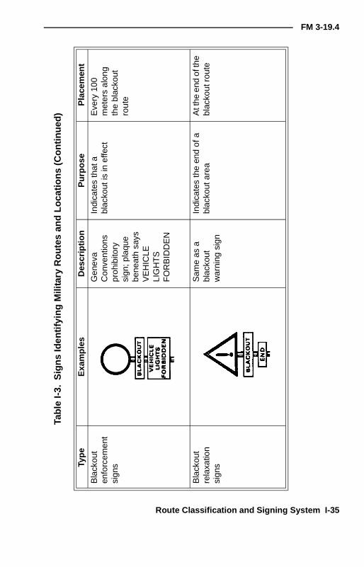
Bla
ckou
ten
forc
emen
tsi
gns
Gen
eva
Con
vent
ions
proh
ibito
rysi
gn;p
laqu
ebe
neat
hsa
ysV
EH
ICLE
LIG
HT
SF
OR
BID
DE
N
Indi
cate
sth
ata
blac
kout
isin
effe
ctE
very
100
met
ers
alon
gth
ebl
acko
utro
ute
Bla
ckou
tre
laxa
tion
sign
s
Sam
eas
abl
acko
utw
arni
ngsi
gn
Indi
cate
sth
een
dof
abl
acko
utar
eaA
tthe
end
ofth
ebl
acko
utro
ute

I-36 Route Classification and Signing System
FM 3-19.4
I-43. Place detour signs next to general traffic signs toidentify the detour. Place the detour sign to the side (leftor right) of the general sign that corresponds to the newdirection to be taken.
I-44. Use signs to mark the entrance to a HQ or aninstallation along with a halt sign or other regulatorysigns. Signs marking turnoffs and roads or tracks shouldinclude a directional disk or a directional arrow. Placesigns to—
• Indicate where vehicles leave a signed route to getto the HQ or the installation.
• Mark the road or track leading to the HQ or theinstallation.
• Mark the entrance to the HQ or the installation.
SIGNING FOR KEY POINTS ON ROUTES
I-45. Place countdown signs (Table I-3, page I-29) at thebeginning and end of a route. Clearly mark SPs and RPswith the appropriate countdown signs. Feeder routes tothe SP may require signs to help the convoys find it.
I-46. Mark route detours with countdown signs showingthe distance to where the detour begins. The signs clearlyindicate the route to be detoured.
I-47. Place countdown signs so that they give clearwarning of the end of the detour. Mark the end of thedetour with a sign reading DETOUR END. Erect awarning sign at the end of the detour to show how toreturn to the original route.
I-48. Position detour signs ahead of time where terrainwill require a defile or the like. Position the signs off theroad, facedown on the ground. To implement the detour,erect the signs.
NOTE: The point where a link route meets thecircuit is an ideal place for MP control. It is thepoint where the circuit and the link route beginand end.
FM 3-19.4
Route Classification and Signing System I-37
I-49. Place signs at junctions of axial and lateral MSRsfrom all four directions. Place countdown signs 300, 200,and 100 meters before the junction.
I-50. To keep the number of signs to a minimum,battalion-size and smaller groups use a directional sign.The space for the military symbol may contain the UINor the unit map-marking symbol. Print the UIN or thesymbol so that it can be read when the arrow is vertical.This allows the sign to be used as a disk direction.
I-51. Therefore, only one type of sign is needed for allpurposes. Put unit signs in place immediately before aunit movement. Remove them as soon as possible afterthe move.
MAIN SUPPLY ROUTE SIGNS
I-52. MSR signs identify MSRs by number, a pictorialsymbol, or a name. Names and pictures—
• Are easier to identify and to remember thannumbers.
• Prevent confusion with link-route signsmarking the routes of units having three-figureidentification numbers.
• Prevent security compromises by removing thechance use of an identification number alreadyused on a map overlay.
I-53. There are two types of MSRs, axial and lateral, ina theater of operations. On the theater of operation'straffic circulation plan—
• Axial MSRs run to and from the forward edge ofthe battle area (FEBA) and are identified by oddnumbers, like 87 or 215. Axial MSRs are shownas solid lines on the traffic circulation planoverlay. Axial routes are represented by apictorial symbol on the route sign and aremarked on the overlay as pictorial; for example,

I-38 Route Classification and Signing System
FM 3-19.4
MSR CLUB (PIC). On axial MSRs, up is towardthe FEBA. It is shown on overlays and signs as aplain arrow. Down is away from the FEBA. It isshown as an arrow with a bar on the tail end.
• Lateral MSRs run parallel to the FEBA and areidentified by even numbers, like 86 or 214.Lateral MSRs are shown as broken lines on thetraffic circulation plan overlay. A named routesign represents lateral routes. The names areshort, three- or four-letter words like fox, ant, orhen. Up and down on lateral MSRs show onlygeneral directions of travel. The generaldirection shown by up or down varies with thetheater of operation and with the location of theFEBA. Up is usually to the north or east; down isusually to the south or west. A plain arrow on anoverlay or sign indicates up; a barred arrowshows down. To avoid confusion on lateralMSRs, use the letters N, E, S, W, NE, SE, NW,and SW on route signs to show the generaldirection of movement.
I-54. Ensure that all route signs are large enough to beread easily in poor light. Size is not specified, but—
• Signs for international use cannot be less than40 centimeters by 33 centimeters.
• Bridge classification signs must conform toSTANAG 2010.
LINK ROUTE SIGNS
I-55. There is no set requirements for the design of linkroute signs (Figure I-10). (Sometimes showing directionwith a white arrow on a black background is enough.) Alink route connects a unit or an activity to an MSR. Adeparting convoy follows the link route signs to theMSR. The convoy follows the MSR until guided off theMSR by signs warning of the need to exit and again
This paragraph implements STANAG 2010.

FM 3-19.4
Route Classification and Signing System I-39
follow link route signs until arriving at its destination.That part of a traveled route coinciding with an MSRwill not have link route signs.
HEADQUARTERS AND INSTALLATION SIGNS
I-56. All signs must be used in HQ and parts of HQ,down to battalion or equivalent level. Examples are—
• Medical installations.• Water points.• Ammunition depots.• TCPs.• Decontamination stations.• Fuel installations.
Figure I-10. Link Route Signing
This paragraph implements STANAG 1059.
SP
222SP
222
222
222RP
300 M
222RP
222
222endLink
routeend RP
Main(222)
xx52
222beginning
Linkroute
beginningor start
222SP
300 M
Main(111)
xx52
222
MSR key
MSR key
I-40 Route Classification and Signing System
FM 3-19.4
I-57. HQ and installation signs show the militarysymbol for the HQ or the installation. For HQ at brigadelevel and above, include the national distinguishingletters given in STANAG 1059. The sizes of the sign andthe symbol are not standardized. The symbol and thebackground must be clearly contrasting colors. Theactual colors used are left to the discretion of eachnation.
DIRECTIONAL SIGNS
I-58. A directional sign (Table I-3, page I-29) must be—• A white disk displaying a black directional
arrow accompanied by a route identificationnumber or name that can be mounted beneaththe disk.
• A white disk mounted or superimposed on ablack rectangular board with the number orname on the board above the disk.
I -59 . Direct ional disks cannot be less than 30centimeters in diameter. Drill eight holes in the disks atequal intervals around the circumference so that theycan be erected with the arrow pointing in the correctdirection.
I-60. Directional signs show directions for axial andlateral routes on hastily prepared routes or verytemporary routes like detours. The initial sign shows theuse of disk directional signs and orders the drivers tofollow the disk direction.
I-61. An MSR may require hundreds of signs. Make thesigns in quantity without the black arrow. Stencil orstick the arrows on later. The superimposed signs areeasiest to store and use. It is hard to secure the twoelements of the circular two-piece signs, and it is hard toposition that sign for display.
I-62. Use yellow instead of white for signs used duringprolonged snowfall conditions or for signs permanentlyerected where there can be prolonged snowfalls.

FM 3-19.4
Route Classification and Signing System I-41
PORTABLE SIGN-MAKING KIT
I-63. The new portable sign-making kit (national stocknumber [NSN] 9905-01-478-3723) is lightweight andsimple to use and contains tools and materials that,when used in conjunction with vehicle BII and locallyavailable materials, produce temporary signs in supportof MP operations. Since the kit is not fully self-contained, the user must plan ahead. The new, lighterkit gives MP units the ability to pack according to theMETT-TC. Even though a significant difference existsbetween signs made with the kit and specifications inSTANAGs (STANAG route signs generally have a blackbackground with white letters, and the kit’s signbackground material is white), it does not differ from thekit it replaces. The soft-sided sign kit comes with whiteplastic bags that can be used to make signs up to 21inches wide by 23 inches high. Figure I-11, shows asample sign; and Table I-4 , page I-42, shows acomponent listing for sign making.
Figure I-11. Sample Sign
Tape tabs for use asfasteners (extend 1 1/2"above and below thefront edge of the sign)
_
Tape border (3/4" to 1" wideon the front edge of the sign)
Reflective tapestrip (1" x 6")
>3"
>16"_

I-42 Route Classification and Signing System
FM 3-19.4
Table I-4. Component Listing
Tools NSNTool bag 5140-01-481-4460Carpenter’s hammer 5120-01-112-8350Utility knifeReplacement blades
5110-00-892-50715110-00-293-2865
Linemans tool 5120-00-293-3485Blacksmith’s/engi-neer’s hammer (3 lb)
5120-00-900-6103
Nested saw set 5110-00-293-0090Staple gun 5120-00-889-1796
Fasteners NSNOne pound of 1.75"steel screw-shanknails (concrete)
5315-00-543-3023
Five pounds of 3.5"(10-12d) commonnails
5315-00-753-3885
One-half pound of 1.5"steel barbed-shanknails (roofing)
5315-01-381-9609
Tape, pressuresensitive (2" x 160',100 miles an hour)
7510-00-074-5124
Staples, 1/2", box of5,000
5315-00-889-2605
Cable ties, pkg of 100 5975-00-156-3253Wire, nonelectrical,1-lb roll
9505-00-293-4208

FM 3-19.4
Route Classification and Signing System I-43
Marking Materials NSNBlack tube-type postermarkers (2 each)
7520-01-336-2856
Red tube-type postermarker
7520-01-336-2857
Blue tube-type postermarker
7520-01-336-2858
Bags, white plastic,trash, 8 gal, roll/box of20 to 30 (2 each)
8105-01-481-4225
Reflective tape (white1" x 150')
9390-00-949-8044
Ribbon, flagging,surveyors (arctic-glopink)
9905-00-194-9703
Table I-4. Component Listing (Continued)