Embed Size (px)
Citation preview

18
iC kr
ap
Round inserts and CoroCut®inserts with -RO geometry
Round inserts are the strongest inserts available, and allow high productivity. Typically aerospace components are large, with large radii and blending profiles
designed to eliminate high stress points allowing round inserts to be used.
Entering angle – kr
The best performance is achieved when the entering angle remains under 45°. This gives a depth of cut of 0.15 x insert diam-eter (the maximum depth of cut should be no greater than 0.25 x diameter).
For larger depths of cut than 25% of the diameter, it is better to use square inserts with a constant 45° entering angle.
Note: this principle also applies to standard inserts when the depth of cut is less than the nose radius.
coskr =(0.5iC–ap)
0.5iC

19
fn
hex
kr
fn
iC
Chip thickness
The chip thickness varies with round inserts, and depends upon the entering angle. With low ap/iC ratios, the feed can be increased in order to raise the chip thickness to a desired level.
Recommended chip thicknesses hex for HRSA are:
Carbide 0.1 to 0.35 mm
Ceramic 0.08 to 0.15 mm
Depth of cut to diameter ratio ap/iC
Depth of cut for insert diameter, in mm Entering angle kr
Feed modi-fication value
Feed min/max mm/r
hex 0.1 mm
hex 0.35 mm
6 mm diameter CoroCut RO insert.
Depth of cut 0.9 mm gives a maximum entering angle kr = 46°.
To machine with:
Minimum 0.1 mm chip thickness the cor-rect feed is 0.14 mm/r.
Maximum 0.35 mm chip thickness the correct feed is 0.49 mm/r.
The surface finish generated has a direct relationship to both the nose radius size and the feed rate. To achieve a certain surface finish, a small nose radius requires a lower feed rate than a large nose radius – which in practical terms means that small nose radius inserts lead to lower productiv-ity.
Therefore, for the highest productivity the nose radius should be as large as possible – the largest of all being round inserts.
Nose radius size mm Insert diameter mm
Maximum feed fn mm/r to achieve surface finish Rmax 8.0 – Ra 1.6 µm – N7
Example
Surface finish
fn =hex
sinkr
3 4 5 6 8 10 12 16
0.25 0.75 1 1.25 1.5 2 2.5 3 4 60° 1.16 0.12 0.410.2 0.6 0.8 1 1.2 1.6 2 2.4 3.2 53° 1.25 0.13 0.440.15 0.45 0.6 0.75 0.9 1.2 1.5 1.8 2.4 46° 1.4 0.14 0.490.1 0.3 0.4 0.5 0.6 0.8 1 1.2 1.6 37° 1.66 0.17 0.580.05 0.15 0.2 0.25 0.3 0.4 0.5 0.6 0.8 26° 2.3 0.23 0.81
0.4 0.8 1.2 1.6 8 10 12 16
0.17 0.22 0.27 0.32 0.5 0.57 0.62 0.7

20
+–
+
–+
Application hints
‘Wrap-around’ is a problem which occurs with round inserts when plunging or pro-filing into corners. Due to high angular engagement creating high cutting pres-sures, the feed needs to be reduced. To reduce this problem, optimized program-ming strategies together with smaller insert radii should be used.
Recommendations
1) Never plunge straight into cut.
2) Roll in and out of cut.
3) Roughing – programmed radius same size as insert diameter.
4) Finishing – insert diameter no greater than 1.75 times programmed radius.
Insert too large for radius
Radius increased for insert
Insert decreased for radius
The component feature to be machined needs to be broken down into stages so that a face and diameter are not machined simultaneously as this will naturally increase the depth of cut and cause ‘wrap-around’
Because of the wrap around problem in the radii, the feed needs to be reduced as the size of cut increases. The larger the dif-ference between the radius and the insert diameter, the less the feed needs to be reduced.
However a good starting point is to use 50% feed rolling into radius compared to parallel cuts.
Programming recommendations
By breaking the part into manageable pieces this method can be used for all pro-filing requirements. The direction of passes can be alternated when using CoroCut and RCGX inserts to best utilise the edge.
‘Trochoidal turning’fn max
50% fn max
Face and diameter
Only diameter
Programmed radius = insert diameter
50% fn máx
21
GC1105 S05F (GC1105)
1115 1105
1105 S05F
S05F
S05F
1105
1105 S05FS05F
S05F
6060
6065
6701115
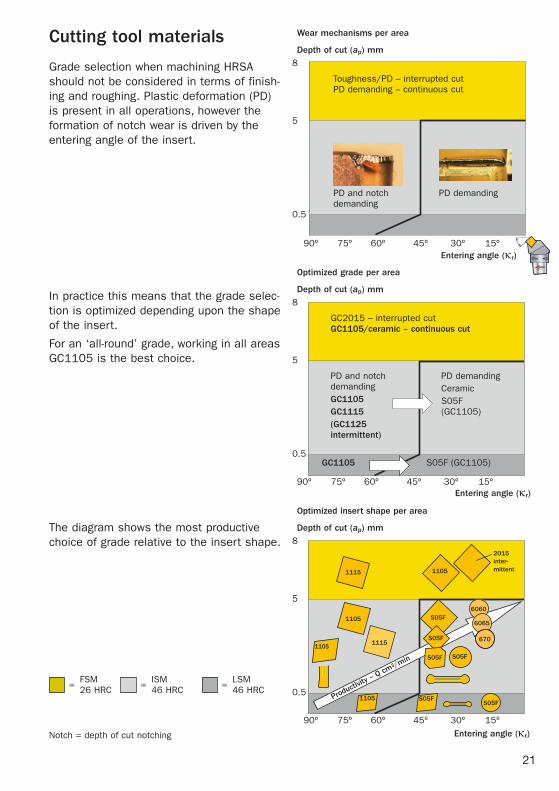
Grade selection when machining HRSA should not be considered in terms of finish-ing and roughing. Plastic deformation (PD) is present in all operations, however the formation of notch wear is driven by the entering angle of the insert.
In practice this means that the grade selec-tion is optimized depending upon the shape of the insert.
For an ‘all-round’ grade, working in all areas GC1105 is the best choice.
The diagram shows the most productive choice of grade relative to the insert shape.
Wear mechanisms per area
8
5
0.5
8
5
0.5
8
5
0.5
Optimized grade per area
Optimized insert shape per area
90º 75º 60º 45º 30º 15º
Depth of cut (ap) mm
90º 75º 60º 45º 30º 15º
90º 75º 60º 45º 30º 15º
Depth of cut (ap) mm
Depth of cut (ap) mm
Entering angle (kr)
Entering angle (kr)
FSM = 26 HRC
Entering angle (kr)
ISM = 46 HRC LSM = 46 HRC
Toughness/PD – interrupted cut PD demanding – continuous cut
Notch = depth of cut notching
PD and notch demanding
PD demanding
GC2015 – interrupted cut GC1105/ceramic – continuous cut
PD and notch demandingGC1105GC1115(GC1125 intermittent)
PD demandingCeramicS05F (GC1105)
2015 inter- mittent
Productivity
– Q cm3/m
in
Cutting tool materials

22
Ceramic insert grades
45º >45º
Ceramic cutting materials offer excellent productivity in roughing operations in FSM and ISM. Their application differs greatly compared to carbide due to their:•High temperature resistance – allows
high cutting speed to be applied to pro-duce a highly plasticised and sheared chip.
•Low toughness – can lead to edge fritter-ing, top slice and notch wear.
Both of these factors mean that for suc-cessful application the following rules need to be applied:• Optimizeenteringangleatabout45° to
reduce notch, round or square inserts should be used.
• Maximumchipthickness–between 0.08 to 0.15 mm.
• Optimizedprogrammingtechniques - to minimize notch on entry and long
passes. - control the cutting arc of engagement in
corners.
There are 2 types of ceramics developed for use in HRSA:•Sialon – (Silicon, Aluminium, Oxygen,
Nitrogen) – a mixture of silicon nitride and aluminium oxide. It has the best chemical stability resisting notch wear:
- CC6060 – optimized choice for long cutting lengths in clean material and for profiling/pocketing with optimized pro-gramming techniques.
- CC6065 – optimized for heavy roughing applications, plunging and machining direct into corner.
•Whiskered ceramic – to provide the improved toughness and bulk strength compared to the traditional ceramic, fibres are included:
- CC670 – first choice for machining of forged components with rough scale and ovality.
Ceramics Carbide
0.5 mm
10–80 mm

23
CC670CC6065
CC6060
vc
hex
CC6065
CC6060
CC670
Programming consideration
Material consideration
Bulk toughness
Grade application areas
Programmed direct into corner/plunging
Programmed with roll-in, roll-out of corner
Skin, scale, ovality High quality forging Pre-machined material
Notch wear resistance
First stage machining – 26 HRC
Intermediate stage machining – 46 HRC
Cutting parametersThe speed should be balanced to create enough heat in the cutting zone to plasti-cise the chip but not too high to unbalance the ceramic.
The feed should be selected to give a chip thickness which is high enough to not work-harden the material but not be too high to cause edge frittering.
Higher feeds and depths of cut require a reduction of the cutting speed.
These boundaries will change depending upon the component material hardness and grain size.
Short tool life – too high cutting temperature
Edge line frittering – too low cutting temperature
Wor
k ha
rden
ing
of
wor
kpie
ce m
ater
ial
Top
slic
e –
high
cut
ting
pres
sure
CC670 200 to 300 m/min 2 mm 0.1 to 0.15 mm/rCC6065 200 to 250 m/min 2 mm 0.15 to 0.2 mm/rCC6060 250 to 300 m/min 2 to 3 mm 0.15 to 0.2 mm/r
Grade Cutting speed, vc Cutting depth, ap Feed, fn
Start cutting data recommendations (RNGN 12, RCGX 12) – Inconel 718 (38 to 46 HRC)
400
300
200
100
00.05 0.1 0.15 0.2

24
fn/2 fn fn/2
Application hints for ceramic inserts
Insert selection
•Wherepossibleuseroundorsquareinserts with a small entering angle and large nose radius.
•Alwaysusethestrongestinsertnoseangle.
•Thickinsertsgiveadditionalstrength.
Pre-chamfering
•Protectstheinsertwhenitfirstentersfrom initial chipping/notch formation.
•Toavoidnotchwearwhenchamfering,use a direction feed at 90° to the pro-duced chamfer.
Turning to a shoulder either:
•Rolluptotheshoulderwitharadiusthesize of the insert diameter to prevent increased depth of cut.
•Reducefeedby50%(fn/2) when approch-ing a shoulder due to the depth of cut increasing.
HighLow
Low HighProductivity
Radial forces
Application hints for round inserts
Too high cutting pressure
Reason Remedy
Top slice
Trouble shooting – wear mechanisms
Reduce feed
Reduce ap on round insert
Use CC670
Sensitive cutting tool mate-rial
Specific to HRSA
Reason Remedy
Notch wear
Careful program-ming tech-niques
Reduce entering angle
Use CC6060, CC6065

25
Notch wearNotch wear can be minimized with good planning and some general advice:
•Useroundinsertswheneverpossible–ensure the relationship between depth of cut ap and insert diameter does not exceed 25%.
•Use45ºenteringanglewhendepthofcutexceeds 25% of iC.
•“Rolloveraction”inprogrammingtoeliminate the need for pre-chamfering and minimize the notch wear. There will be one contact point where the insert hits the hard scale/surface at the corner of the component and one different point at the ap line.
•Rampingensuresthatanydamageisspread out along the cutting edge. The depth of cut should be varied between 25% iC to 15% (do not ramp to zero).
•Multiplepasseswithvaryingap can be an alternative.
•ForRCGX/RPGXinserts,programinbothdirections to utilise more edges on the insert.
mm mm
6.35 0.9 9.52 1.412.70 1.919.06 2.825.40 3.8

Need more help?There's always a Yellow Coat expert available to help you get more out of every application.
www.sandvik.coromant.com
Looking for more good information?
Visit our Facebook Tech Shares page to download this and other complete application guides.
See Tech Shares Now