Embed Size (px)
Citation preview

MODEL NUMBER SO 88000
RW SPINOFFOPERATION MANUAL
ROUND BALE FEEDER


RW SPINOFF ROUND BALE FEEDER (MODEL SO 88000)
RW SPINOFF OPERATION MANUAL
Table of Contents
Introduction ............................................................................................................4
Safety Instructions ................................................................................................4
Packaging Summary..............................................................................................5
Tools Needed ........................................................................................................6
Assembly Instructions ............................................................................................6
Mounting Instructions ............................................................................................9
Operation Instructions............................................................................................9
Operation Tips......................................................................................................11
Maintenance ........................................................................................................11
Frequently Asked Questions................................................................................12
Troubleshooting....................................................................................................12
Service ................................................................................................................13
Specifications ......................................................................................................13
Warranty ..............................................................................................................14
Copyright © 2001 ASI. All Rights Reserved.
ASIPO Box 160 T (800) 445-10011525 East 5th Street T (308) 235-4685 www.rw-products.comKimball, NE 69145 F (308) 235-4687 [email protected]
noitamrofnIesahcruP
:relaeD
:nosrepselaS
:sserddA
:piZ,tS,ytiC
:enohP
:xaF
:liamE
:etiSbeW
:etaDesahcruP
rebmuNlaireS :

- 4 - (800) 445-1001ASI
SAFETY INSTRUCTIONSPlease read carefully, as these messages are important for your well being.Disregarding these safety precautions could result in serious injury or death.
The SpinOff is designed to move and feed round bales. Do not use it for anyother purpose.
DANGER: The rotating hay spikes could cause serious injury or death. Keep away from the hayspikes when the tractor is running. Shut the tractor off when working around the rear of the tractor.The DANGER DECAL is attached to the SpinOff in two (2) locations. The locations are shown on thecompleted unit photo on page eight (8).
DANGER: Do not attempt to ride on the frame or spike of the SpinOff! Be careful when backing upto a bale. Make sure that people and animals are not between the spike and the bale.
WARNING: Keep all guards in place when the SpinOff is in operation or when the tractor isrunning. It is important to shut off tractor and disconnect hydraulic hoses when servicing the chainor performing any other maintenance.
WARNING: Replace the chain guard if damaged or lost. Never operate without the chain guard.
WARNING: You may need to add weight to the front end of the tractor to safely handle large bales.
CAUTION: All decals must be kept on the SpinOff! They must be kept in a legiblecondition. If they become damaged, are missing or are destroyed, new decals can beobtained from ASI at no charge by calling (800) 445-1001. When new decals are attachedthey must be located as shown on the completed unit photo on page eight (8). Install thenew decals on a clean dry surface.
INTRODUCTIONThank you for purchasing the RW SpinOff. We think you will be very pleased with the performance of this round balemover/feeder. Please read this manual, as that will insure the best results with your new RW SpinOff. Also rememberto completely fill out the warranty card enclosed and mail it back to ASI.
ASI is a family owned manufacturing company that has been in business since 1958, serving the agriculturalcommunity with many fine quality products. We produce the following products at our factory in Kimball, Nebraska:the RW PreCleaner, RW ChaffEliminator, and the RW SpinOff. Please visit http://www.rw-products.com forinformation on our other products.
IMPORTANTThe following words and symbols have special meaning in this operation manual.
DANGER: Text set off in this manner indicates that failure to follow directions will result in bodilyharm or loss of life.
WARNING: Text set off in this manner indicates that failure to follow directions may result inbodily harm or loss of life.
CAUTION: Text set off in this manner indicates that failure to follow directions may result inequipment damage.
LT 300 LT 303

- 5 -ASI (800) 445-1001
PACKAGING SUMMARY
metI ytQ traPrebmuN noitpircseD metI ytQ traP
rebmuN noitpircseD
1 1 10088OS emarFniaM 07088OSegakcaPtloB
2 1 62188OS tfahS 21 2 22088OS niPhctiHrewoL
9 1 22188OS ylbmessArennipS 31 2 62088OS recapSniPhctiHrewoL
17088OSxoBstraP 41 2 839LB "61/7niPhcnyL
3 1 08088OS tekcarBtnuoMrotoM 51 6 049LB "2/1rehsaWtalF
4 1 00482OS *rotoMciluardyH 61 3 939LB "2/1rehsaWkcoL
5 1 76282OS *evlaVnoihsuC 71 1 0001LB "5x31-"2/1tloBxeH
6 2 91182OS )"06(esoHciluardyH 81 5 339LB 31-"2/1tuNxeH
7 1 26042OS tekcorpS 91 2 539LB "4/3x31-"2/1tloBxeH
8 1 46042OS hctiP0705#niahCrelloR 02 2 439LB "2/11x31-"2/1tloBxeH
01 1 03088OS ylbmessAralloC 12 9 379LB "61/5rehsawtalF
11 1 66088OS ylbmessAdrauGniahC 22 2 129LB "4/3x81-"61/5tloBxeH
1 1004ATL launaMnoitarepO 32 1 249LB 81-"61/5tuNxeH
1 860TL draCytnarraW 42 2 8001LB "2/11x31-"2/1tloBegairraC
52 4 1001LB *”2/12x81-61/5-wercSpaCdaeHtekcoS
.delbmessa-erperarotoMciluardyHehtdnaevlaVnoihsuCehT*
- 6 - (800) 445-1001ASI
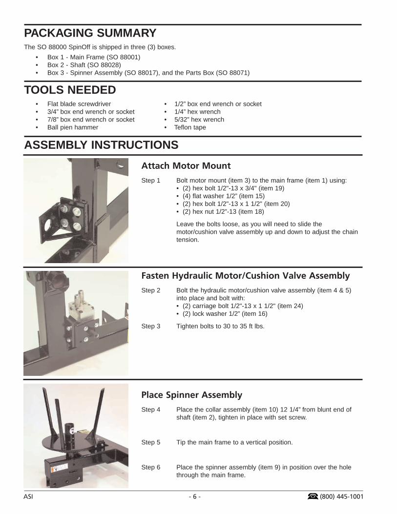
Attach Motor Mount
Step 1 Bolt motor mount (item 3) to the main frame (item 1) using:• (2) hex bolt 1/2"-13 x 3/4" (item 19)• (4) flat washer 1/2” (item 15)• (2) hex bolt 1/2"-13 x 1 1/2" (item 20)• (2) hex nut 1/2”-13 (item 18)
Leave the bolts loose, as you will need to slide themotor/cushion valve assembly up and down to adjust the chaintension.
Fasten Hydraulic Motor/Cushion Valve Assembly
Step 2 Bolt the hydraulic motor/cushion valve assembly (item 4 & 5)into place and bolt with:• (2) carriage bolt 1/2"-13 x 1 1/2" (item 24)• (2) lock washer 1/2” (item 16)
Step 3 Tighten bolts to 30 to 35 ft lbs.
Place Spinner Assembly
Step 4 Place the collar assembly (item 10) 12 1/4” from blunt end ofshaft (item 2), tighten in place with set screw.
Step 5 Tip the main frame to a vertical position.
Step 6 Place the spinner assembly (item 9) in position over the holethrough the main frame.
ASSEMBLY INSTRUCTIONS
PACKAGING SUMMARYThe SO 88000 SpinOff is shipped in three (3) boxes.
• Box 1 - Main Frame (SO 88001)• Box 2 - Shaft (SO 88028)• Box 3 - Spinner Assembly (SO 88017), and the Parts Box (SO 88071)
TOOLS NEEDED• Flat blade screwdriver • 1/2” box end wrench or socket• 3/4” box end wrench or socket • 1/4” hex wrench• 7/8” box end wrench or socket • 5/32” hex wrench• Ball pien hammer • Teflon tape

- 7 -ASI (800) 445-1001
Install Shaft
Step 7 Insert the shaft through the spinner assembly into themain frame. Align the holes of the shaft with the holesin the main frame, and bolt using:• (1) hex bolt 1/2"-13 x 5" (item 17)• (1) lock washer 1/2” (item 16)• (2) flat washer 1/2” (item 15) on each side• (1) hex nut 1/2”-13 (item 18)
Step 8 Push the collar assembly down tight against thespinner assembly. Lock the collar assembly into placewith the set screw.
Step 9 Use a grease gun to grease the spinner assembly viathe grease zerk.
Install and Align Sprocket
Step 10 Tip the unit to a horizontal position.
Step 11 Install the sprocket (item 7) onto the hydraulic motorshaft with the set screw toward the motor.
Step 12 Align the small sprocket with the large sprocket on thespinner assembly using a straight edge.
Step 13 Tighten the set screw on the small sprocket.
Install Roller Chain
Step 14 Install the roller chain (item 8) using the master link.
Step 15 Tighten the chain by moving the motor mountdownward. Tighten the bolts on the motor mount to theframe. The chain should have1/8" to 3/16" deflection.
Note: The chain will have tobe readjusted after the first 3or 4 bales, as it will stretchwith use.
Attach Chain Guard
Step 16 Opening the chain guard assembly (item 11) and slideit in from the left side of the SpinOff over the chain.
Step 17 Close the chain guard cover and latch.
Step 18 Bolt into place using:• (2) hex bolt 5/16"-18 x 3/4" (item 22)• (3) flat washer 5/16” (item 21)• (1) hex nut 5/16” (item 23)Extra flat washers are included to shim out cover ifnecessary for chain clearance.

- 8 - (800) 445-1001ASI
Insert Lower Hitch Pins
Step 19 Insert (2) lower hitch pins (item 12) and lock into placewith (2) lynch pins (item 14).
Note: Insert (2) lower hitch pin spacers (item 13) ifnecessary for your hitch.
Attach Hydraulic Hoses
Step 20 Attach (2) hydraulic hoses (item 6) to ports. Rememberto use teflon tape around the hose threads.
Step 21 Add a pair of male hydraulic couplers with 1/2" femalepipe thread (not included) to the other end of thesehoses. Remember to use teflon tape around the hosethreads..
The Completed Unit
Step 22 The completed unit (quick couplers not provided).

- 9 -ASI (800) 445-1001
MOUNTING INSTRUCTIONSThe SpinOff is both a mover and feeder for large round bales. It mounts on all category II and category III three pointhitches, and on most quick hitch. One remote two-way hydraulic outlet is required to operate the feeding function. Thetractor’s hydraulic system should produce at least 1500 psi pressure and 8 gpm flow.
• Category II three point arms - no spacer.
• Category III three point arms - use the flanged spacer withthe ring toward the center. Place arms at the outer end oflower pins.
• Category II or category III quick hitch - use the flangedspacer with the ring toward the edge.
You will need to supply a pair of male hydraulic couplers with1/2" female pipe thread and an upper link pin. Install the snapcouplers on the ends of the hoses using pipe sealant. Makesure that no sealant gets into the hydraulic system. Keep thecoupler ends clean.
OPERATION INSTRUCTIONS
USING THE SPINOFF AS A BALE MOVER
1. Install the SpinOff on the tractor in accordance with mountinginstructions and common three point mounting practices. The hydraulichoses need not be coupled for moving bales; however, you shouldkeep all hose ends and couplers clean.
2. Back the tractor toward the bale from either end while keeping thecenter shaft horizontal and near the center of the bale.
3. Continue backing until the center shaft and spinner are fully insertedinto the bale.
4. Raise the three point hitch.
CAUTION: Attempting to raise the bale with the center shaft andspinner only partially inserted may cause the unit to bend orbreak.
5. Drive to the desired location, lower the bale to the ground and driveaway from the bale.
Category II
Category III
Category II & IIIQuick Couplers

- 10 - (800) 445-1001ASI
USING THE SPINOFF AS A BALEFEEDER
1. Install the SpinOff on the tractor in accordance withmounting instructions and common three pointmounting practices.
2. Connect the hydraulic hoses. Make sure the ends areclean before insertion.
3. Back the tractor toward either end of the bale whilekeeping the center shaft horizontal and near thecenter of the bale.
4. Continue backing until the center shaft and spinnerare fully inserted into the bale.
5. Raise the three point hitch.
6. Drive to the desired range feeding location.
7. Remove the bale twine and dispose of it properly.
8. Do not lower the bale to the ground. The rear end ofthe bale should be higher than the forward end tokeep the bale from sliding off the center shaft.
9. Select a tractor gear slightly above mid-range.
10. Set the throttle a little above idle.
11. When the tractor is in a forward motion, slowlyengage the hydraulic lever to rotate the bale. This willunroll the hay into a windrow.
12. Adjust the forward speed of the tractor to adjust thewindrow size. A faster speed for a smaller windrow, aslower speed for a larger windrow.
13. Experiment with different forward speeds and rotationof the bale to unroll the desired windrow.
OPERATION INSTRUCTIONS

- 11 -ASI (800) 445-1001
OPERATION TIPS• Select a lower gear and higher engine rpm if hay is tightly packed and does not unroll freely. Direction of rotation
can be changed while in motion to dislodge extremely tight hay. This will not damage the SpinOff unit.
• If the hay tends to come off in a larger quantity than desired, use a higher gear and lower engine rpm and/or rollintermittently rather than continuously.
• Centrifugal force separates the outer layer from the remaining portion of the bale, therefore, higher rpm (enginethrottle setting) may be necessary as the bale diameter becomes smaller.
• A small core of hay may need to be slipped from the center shaft by hand. This can be minimized in many typesof hay by stabbing the bale approximately 6" off center before beginning to unroll hay.
DANGER: Shut off the tractor before removing hay by hand!
• Dense core bales unroll more satisfactorily than loose core bales.
• Adjust the forward speed of the tractor to adjust the windrow size. A faster speed for a smaller windrow, a slowerspeed for a larger windrow.
• Experiment with different forward speeds and rotation of the bale to unroll the desired windrow.
MAINTENANCEThe SpinOff requires minimum maintenance.
WARNING: Shut off the tractor and disconnect hydraulic hoses when performing maintenance!
1. Keep all bolts tight.
2. Keep the sprockets in alignment.
3. Grease the zerk on the spinner every fifty (50) bales fed or at least twice a season.
4. Apply lubricating oil to the roller chain every fifty (50) bales fed or at least twice a season.
5. Keep the chain adjusted to approximately 1/8" to 3/16" deflection. The chain will have to be adjusted after the first3 or 4 bales, as it will stretch with use.
6. Adjust the chain by loosening the bolts holding the motor mount to the frame. Slide the motor down. Tighten thebolts and recheck for proper tension.

- 12 - (800) 445-1001ASI
FREQUENTLY ASKED QUESTIONSWhat is the maximum weight of a bale that can be unrolled with an RW SpinOff?
2,000 lbs.How much does the RW SpinOff weigh?
The RW SpinOff ships by UPS in 3 boxes that weigh 255 lbs. total. The top link pin and the quick couplersfor the two hydraulic hoses are not included.
Can the RW SpinOff be shipped UPS?Yes, in 3 boxes that weigh 255 lbs. total.
What category tractor hitch does the RW SpinOff fit?Category II & III hitches. If you have a Category I hitch, you can special order a SO 88000-2, which is aspecial version of the RW SpinOff for Category I hitches.
TROUBLESHOOTINGChain or Sprocket Breakage
• The chain may be too tight. Adjust the chain to allow 3/16" deflection. When reversing the direction ofrotation, allow the bale to almost come to a complete stop before reversing.
• The cushion valve may be out of adjustment. Contact ASI for assistance on proper cushion valveadjustment.
• The RW SpinOff must be run with the chain guard in place to prevent foreign objects from getting caught inthe chain and causing damage.
Chain Coming Off
• The small sprocket and large sprocket may not be aligned properly. Align the small sprocket with the largesprocket on the spinner assembly using a straight edge, per the assembly instructions, Step 9.
• The chain may be too loose. Adjust the chain to allow 3/16" deflection.
Bale Won’t Unwind
• The twine may still be on the bale. If it is, take the twine completely off to avoid tangling on the RW SpinOffwhen the bale is rotating.
• The bale may be frozen. Try bouncing the bale lightly on the ground to loosen it. You may have to use theground to slough the first layer off the bale and get it unrolling.
• The bale may be wrapped too tightly. Make certain that all the twine is cut. Try bouncing the bale lightly onthe ground to loosen it.

- 13 -ASI (800) 445-1001
SERVICETo have your RW SpinOff serviced, please contact the RW SpinOff dealer that sold you your SpinOff.
If you do need to return something to the factory, you must have a Return Authorization Number, otherwise yourreturn will be refused.
For Factory Return Authorization:
ASIPO Box 1601525 E 5th StKimball, NE 69145
T (308) 235-4685F (308) 235-4687
SPECIFICATIONSChain
#50 70 pitch link roller chain, includes master link.Sprocket ratio 3.75
UnitHeight 26-3/4"Width 44-3/4"Depth 64-3/4"Weight 255 lbs
Hydraulic MotorCharlynn Motor manufactured by Eaton Hydraulics.Model #101 - 1044 9.7 CID.2 bolt mounting flange.Minimum 1500 PSI and 8-10 GPM required.
Cushion ValveFactory set relief at 1750 PSI.Range of adjustable cushion valve: 500 PSI Min - 3500 PSI Max.Single replaceable cartridge.WARNING: Call factory before you attempt any adjustment of the cushion valve!
Hydraulic Hoses(2) 1/2" NPT x 60" long - quick couplers not provided.
MaterialFrame M 1020 STL - 4" Sq x 1/4" Wall.Shaft 1045 STL - 2-1/4" Dia - 60" long.
Proudly Manufactured in the USA.

- 14 - (800) 445-1001ASI
LIMITED WARRANTYRW SPINOFF
ACCESSORY SALES, INC. ("ASI") warrants this Product (including any accessories) against defects in material orworkmanship as follows:
1. LABOR: For a period of 90 days from the original date of purchase, if the Product is determined to be defective, ASI willrepair or replace the Product at no charge. After this 90-day period, you must pay for all labor charges.
2. PARTS: For a period of one (1) year from the original date of purchase, ASI will supply, at no charge, new or rebuiltreplacements in exchange for defective parts. Any replacements will be warranted for the remainder of the original warrantyperiod or (90) days from installation by ASI's authorized facility, whichever is longer.
3. ACCESSORIES: Parts and labor for all accessories are for one (1) year.
To obtain warranty service, you must take the Product, or deliver the Product freight prepaid, in either its original packaging orpackaging affording an equal degree of protection, to an ASI authorized RW SPINOFF service facility. Please see below for thenumber to call to locate the closest facility.
This warranty does not cover customer instruction, installation, or adjustment problems.
This warranty does not cover cosmetic damage or damage due to acts of God, accident, misuse, abuse, negligence, ormodification of, or to any part of the Product. This warranty does not cover improper assembly (if self assembled), loss of useof the product, or wasted time due to product malfunction. This warranty does not cover damage due to improper operation ormaintenance, connection to improper hydraulic system, or attempted repair by anyone other than a facility authorized by ASI toservice the Product. This warranty does not cover Products sold AS IS or WITH ALL FAULTS. This warranty is valid only in theUnited States.
Proof of purchase in the form of a bill of sale or receipted invoice, which is evidence that the unit is within the Warranty periodmust be presented to obtain warranty service.
REPAIR OR REPLACEMENT AS PROVIDED UNDER THIS WARRANTY IS THE EXCLUSIVE REMEDY OF THECONSUMER. ASI SHALL NOT BE LIABLE FOR ANY INCIDENTAL OR CONSEQUENTIAL DAMAGES FOR BREACH OFANY EXPRESS OR IMPLIED WARRANTY ON THIS PRODUCT. IN NO EVENT SHALL ASI BE LIABLE FOR ANYINCIDENTAL OR CONSEQUENTIAL DAMAGES WHATSOEVER ARISING OUT OF THE USE OR INABILITY TO USE THEPRODUCT. UNDER NO CIRCUMSTANCES SHALL ASI's LIABILITY, IF ANY, EXCEED THE PURCHASE PRICE PAID FORTHE PRODUCT. EXCEPT TO THE EXTENT PROHIBITED BY APPLICABLE LAW, ANY IMPLIED WARRANTY OFMERCHANTABILITY OR FITNESS FOR A PARTICULAR PURPOSE ON THIS PRODUCT IS LIMITED IN DURATION TOTHE DURATION OF THIS WARRANTY.
This warranty is invalid if the factory-applied serial number has been altered or removed from the Product.
Some states do not allow the exclusion or limitation of incidental or consequential damages, or allow limitations on how longan implied warranty lasts, so the above limitations or exclusions may not apply to you. In addition, if you enter into a servicecontract with the ASI Partnership within 90 days of the date of sale, the limitation on how long an implied warranty lasts doesnot apply to you. This warranty gives you specific legal rights, and you may have other rights, which vary, from state to state.
To locate the service center or dealer nearest you, for service assistance or resolution of a service problem, for productinformation, operational questions, or an accessory or part not available from your authorized dealer, contact:
ASI RW SPINOFF INFORMATION CENTERPO Box 1601525 E 5th StKimball, NE 69145
T (308) 235-4685F (308) 235-4687


ASIPO Box 160 T (800) 445-10011525 East 5th Street T (308) 235-4685 www.rw-products.comKimball, NE 69145 F (308) 235-4687 [email protected]
Copyright © 2001 ASI. All Rights Reserved.
Information and specifications are subject to change without notice. Please check www.rw-spinoff.com for the latest information.
LTA 4001 Revised: 08-17-01