Embed Size (px)
Citation preview
Rough-in BoxRF500
Installation Instructions
Important Safety Instructions/Instructions de sécurité importantes Explication des symboles
Explanation Of Symbols/Explication des symboles
L
N
LIVE/PHASE
PROTECTIVE EARTH (GROUND)/PROTECTION DE MISE A LA TERRE
NEUTRAL/NEUTRE
AC CURRENT/COURANT ALTERNATIF
WARNING/ATTENTION TENSION
DANGEROUS VOLTAGE/DANGEREUSE
PORTABLE CART WARNING/AVERTISSEMENT LIE AU CHARIOTPORTATIF
1) Read these instructions./Lisez ces instructions.2) Keep these instructions./Conservez ces instructions.3) Heed all warnings./Tenez compte de tous les avertissements.4) Follow all instructions./Suivez toutes les instructions. 5) Do not use this apparatus near water./N'utilisez pas ce dispositif à proximité d'eau.6) Clean only with dry cloth./Utilisez uniquement un chiffon sec pour le nettoyage.7) Do not block any ventilation openings. Install in accordance with the manufacturer's instructions./Ne bloquez pas les orifices d'aération. Installez le dispositif conformément aux instructions du fabricant.8) Do not install near any heat sources such as radiators, heat registers, stoves, or other apparatus (including amplifiers) that produce heat./Ne l'installez pas à proximité de sources de chaleur, telles que des radiateurs, bouches de chauffage, fours ou autres appareils (y compris les amplificateurs) qui génèrent de la chaleur.9) Do not defeat the safety purpose of the polarized or grounding type plug. A polarized plug has two blades with one wider than the other. A grounding type plug has two blades and a third grounding prong. The wide blade, or the third prong are provided for your safety. If the provided plug does not fit your outlet, consult an electrician for replacement of the obsolete outlet./Ne supprimez pas la fonction de sécurité de la prise polarisée ou de mise à la terre. Une prise polarisée possède deux lames, dont l'une est plus large que l'autre. Une prise de mise à la terre possède deux lames, et une troisième broche pour la mise à la terre. La lame la plus large ou la troisième broche ont pour but d'assurer votre sécurité. Si la prise fournie ne s'adapte pas à votre prise murale, consultez un électricien pour remplacer cette dernière. 10) Protect the power chord from being walked on or pinched particularly at plugs, convenience receptacles, and at the point they exit from the apparatus./ Protégez le cordon d'alimentation afin qu'il soit à l'abri des piétinements ou qu'il ne soit pas écrasé, tout particulièrement au niveau des fiches, des prises de courant et de sa sortie du dispositif.11) Only use attachments/accessories specified by the manufacturer./Utilisez uniquement les pièces et accessoires spécifiés par le fabricant.12) Use only with the cart, stand, tripod, bracket, or table specified by the manufacturer, or sold with the apparatus. When a cart is used, use caution when moving the cart/apparatus combination to avoid injury from tip-over./Utilisez uniquement le chariot, le pied, le trépied, le support ou la table recommandés par le fabricant ou fournis avec l'appareil. Si un chariot est utilisé, déplacez l'ensemble chariot-appareil avec précaution afin de ne pas le renverser, ce qui pourrait entraîner des blessures.13) Unplug the apparatus during lightning storms or when unused for long periods of time./Débranchez l'appareil en cas d'orage ou si vous ne l'utilisez pas pendant une période prolongée.14) Refer all servicing to qualified service personnel. Servicing is required when the apparatus has been damaged in any way, such as power-supply chord or plug is damaged, liquid has been spilled or objects have fallen in to the apparatus, the apparatus has been exposed to rain or moisture, does not operate normally, or has been dropped./Confiez l'entretien à un personnel qualifié. L'entretien est nécessaire lorsque l'appareil a été endommagé, par exemple si le cordon d'alimentation ou sa fiche est abîmé, si du liquide a été versé sur l'appareil ou des objets y ont été introduits, si l'appareil a été soumis à la pluie ou l'humidité, s'il ne fonctionne pas correctement ou s'il est tombé. 15) To prevent injury, this apparatus must be securely attached to the floor/wall in accordance with the installation instructions./Afin d'éviter les blessures, cet appareil doit être solidement fixé au sol/mur, conformément aux instructions d'installation.
page 1
Safety/Sécurité
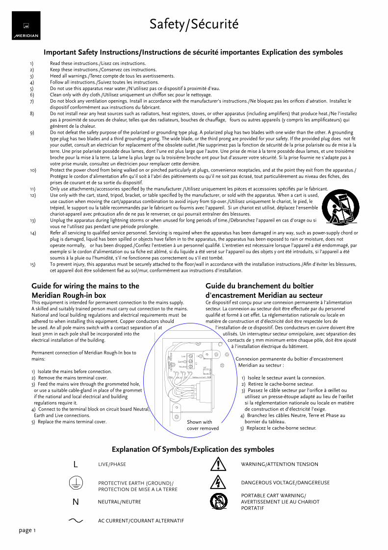
Guide for wiring the mains to theMeridian Rough-in boxThis equipment is intended for permanent connection to the mains supply.A skilled and suitably trained person must carry out connection to the mains.National and local building regulations and electrical requirements must beadhered to when installing this equipment. Copper conductors shouldbe used. An all pole mains switch with a contact separation of atleast 3mm in each pole shall be incorporated into theelectrical installation of the building.
Permanent connection of Meridian Rough-In box tomains:
1) Isolate the mains before connection.2) Remove the mains terminal cover.3) Feed the mains wire through the grommeted hole, or use a suitable cable-gland in place of the grommet if the national and local electrical and building regulations require it.4) Connect to the terminal block on circuit board Neutral, Earth and Live connections.5) Replace the mains terminal cover.
Shown withcover removed
Guide du branchement du boîtierd'encastrement Meridian au secteurCe dispositif est conçu pour une connexion permanente à l'alimentationsecteur. La connexion au secteur doit être effectuée par du personnelqualifié et formé à cet effet. La réglementation nationale ou locale enmatière de construction et d'électricité doit être respectée lors de l'installation de ce dispositif. Des conducteurs en cuivre doivent être utilisés. Un interrupteur secteur omnipolaire, avec séparation des contacts de 3 mm minimum entre chaque pôle, doit être ajouté à l'installation électrique du bâtiment.
Connexion permanente du boîtier d'encastrement Meridian au secteur :
1) Isolez le secteur avant la connexion. 2) Retirez le cache-borne secteur. 3) Passez le câble secteur par l'orifice à œillet ou utilisez un presse-étoupe adapté au lieu de l'œillet si la réglementation nationale ou locale en matière de construction et d'électricité l'exige. 4) Branchez les câbles Neutre, Terre et Phase au bornier du tableau. 5) Replacez le cache-borne secteur.
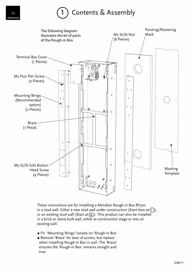
These instructions are for installing a Meridian Rough-in Box RF500in a stud wall. Either a new stud wall under construction (Start here at 1 ),or an existing stud wall (Start at 4 ). This product can also be installedin a brick or stone built wall, either at construction stage or into anexisting wall.
○ Fit ‘Mounting Wings’ loosely on ‘Rough-in Box’○ Remove ‘Brace’ for ease of access, but replace when installing Rough-in Box in wall. The ‘Brace’ ensures the ‘Rough-in Box’ remains straight and true.
Mounting Wings(Recommended
option)(2 Pieces)
M5 St/St Nut(8 Pieces)
Painting/PlasteringMask
MarkingTemplate
M5 St/St Sckt Button Head Screw
(4 Pieces)
Terminal Box Cover(1 Pieces)
M3 Pozi Pan Screw(2 Pieces)
Brace(1 Piece)
page 2
1 Contents & Assembly
The following diagramillustrates the kit of partsof the Rough-in Box
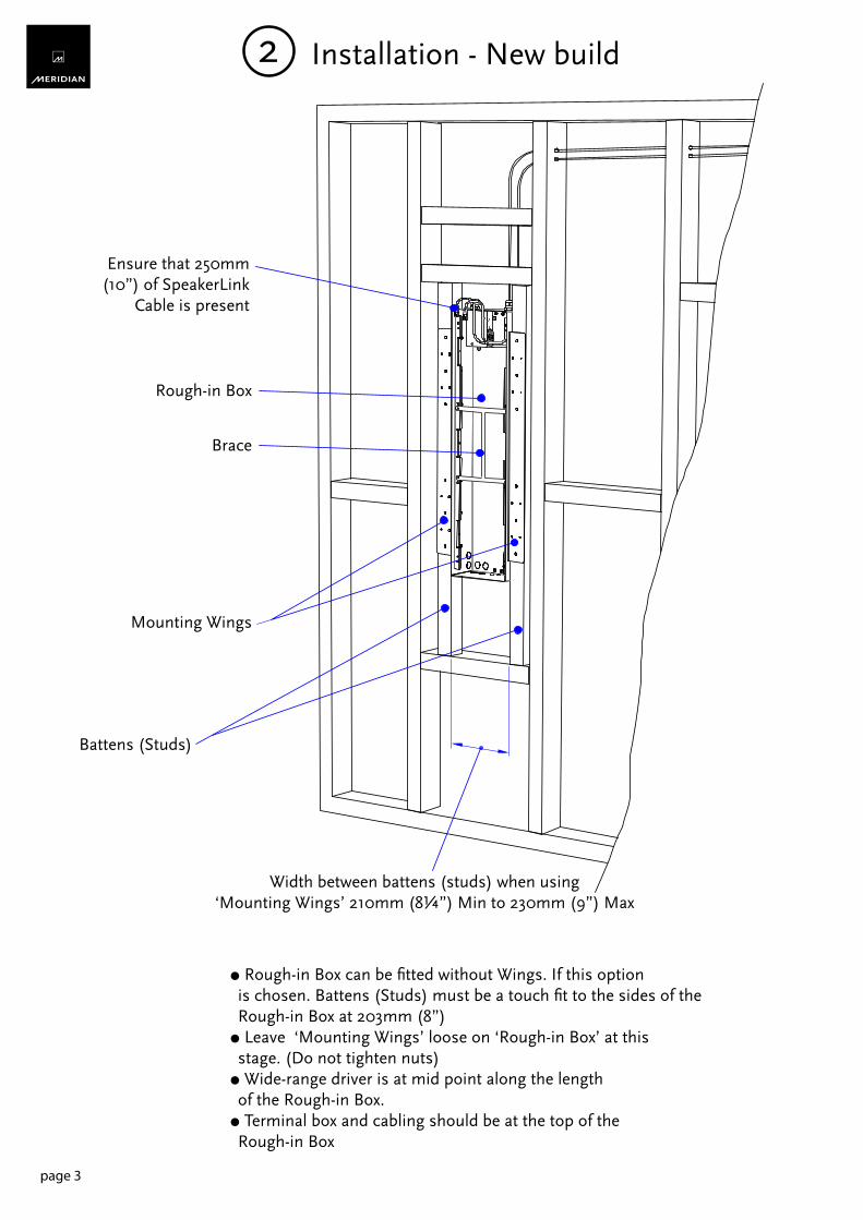
○ Rough-in Box can be fitted without Wings. If this option is chosen. Battens (Studs) must be a touch fit to the sides of the Rough-in Box at 203mm (8”)○ Leave ‘Mounting Wings’ loose on ‘Rough-in Box’ at this stage. (Do not tighten nuts)○ Wide-range driver is at mid point along the length of the Rough-in Box.○ Terminal box and cabling should be at the top of the Rough-in Box
Ensure that 250mm(10”) of SpeakerLink
Cable is present
Rough-in Box
Brace
Mounting Wings
Width between battens (studs) when using‘Mounting Wings’ 210mm (8¼”) Min to 230mm (9”) Max
2
page 3
Battens (Studs)
Installation - New build
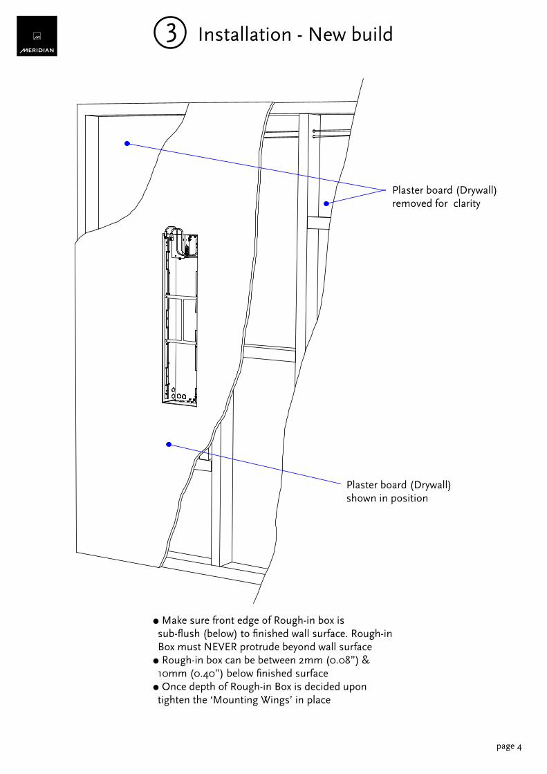
○ Make sure front edge of Rough-in box is sub-flush (below) to finished wall surface. Rough-in Box must NEVER protrude beyond wall surface○ Rough-in box can be between 2mm (0.08”) & 10mm (0.40”) below finished surface○ Once depth of Rough-in Box is decided upon tighten the ‘Mounting Wings’ in place
Plaster board (Drywall)shown in position
Plaster board (Drywall)removed for clarity
3
page 4
Installation - New build
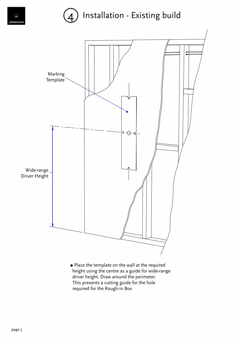
Wide-rangeDriver Height
○ Place the template on the wall at the required height using the centre as a guide for wide-range driver height. Draw around the perimeter. This presents a cutting guide for the hole required for the Rough-in Box
4 Installation - Existing build
page 5
MarkingTemplate
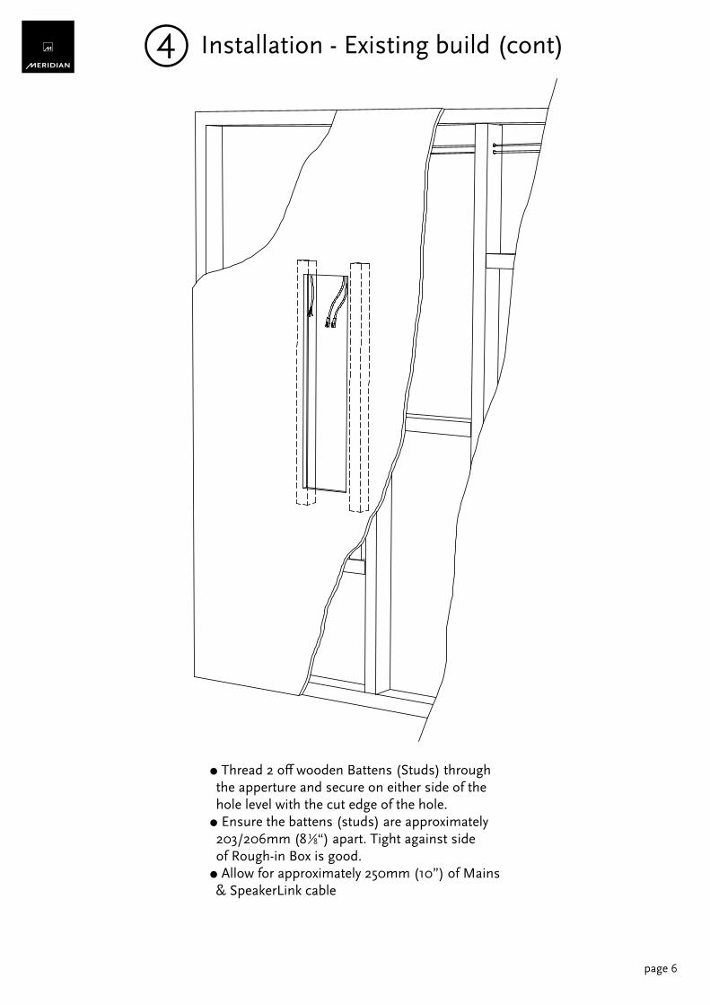
○ Thread 2 off wooden Battens (Studs) through the apperture and secure on either side of the hole level with the cut edge of the hole. ○ Ensure the battens (studs) are approximately 203/206mm (8 “) apart. Tight against side of Rough-in Box is good. ○ Allow for approximately 250mm (10”) of Mains & SpeakerLink cable
1 8
page 6
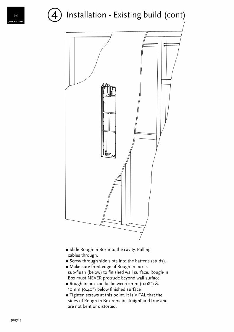
4 Installation - Existing build (cont)
page 7
○ Slide Rough-in Box into the cavity. Pulling cables through. ○ Screw through side slots into the battens (studs).○ Make sure front edge of Rough-in box is sub-flush (below) to finished wall surface. Rough-in Box must NEVER protrude beyond wall surface○ Rough-in box can be between 2mm (0.08”) & 10mm (0.40”) below finished surface○ Tighten screws at this point. It is VITAL that the sides of Rough-in Box remain straight and true and are not bent or distorted.
4 Installation - Existing build (cont)
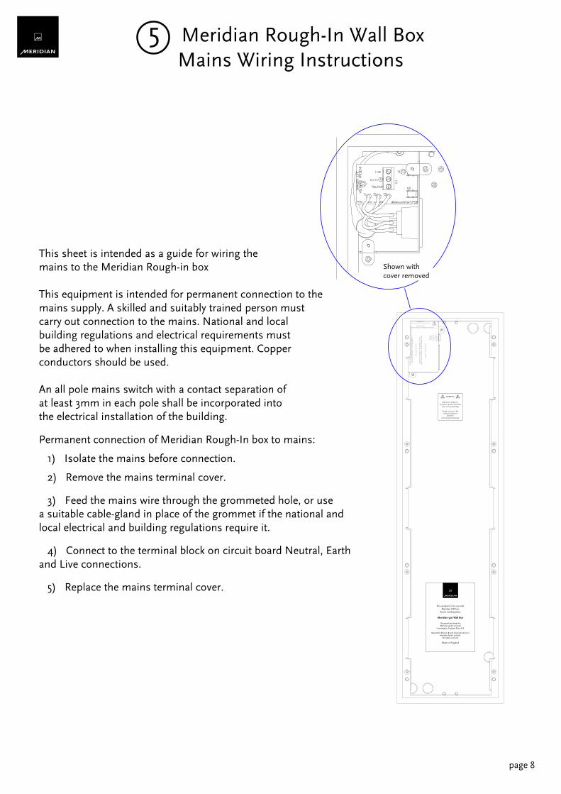
This sheet is intended as a guide for wiring themains to the Meridian Rough-in box
This equipment is intended for permanent connection to themains supply. A skilled and suitably trained person mustcarry out connection to the mains. National and localbuilding regulations and electrical requirements mustbe adhered to when installing this equipment. Copperconductors should be used.
An all pole mains switch with a contact separation ofat least 3mm in each pole shall be incorporated intothe electrical installation of the building.
Permanent connection of Meridian Rough-In box to mains:
1) Isolate the mains before connection.
2) Remove the mains terminal cover.
3) Feed the mains wire through the grommeted hole, or usea suitable cable-gland in place of the grommet if the national andlocal electrical and building regulations require it.
4) Connect to the terminal block on circuit board Neutral, Earthand Live connections.
5) Replace the mains terminal cover.
WARNING!RISK OF ELECTRIC SHOCK - DO NOT OPEN
ATTENTION!NE PAS OUVRIR - RISQUE DE DÉCHARGE ÉLECTRIQUE!
REF
ER T
O IM
POR
TAN
T SA
FETY
INST
RU
CTI
ON
S B
EFO
RE
INST
ALL
ATIO
NPR
IÈR
E D
E SE
RÉF
ÉRER
AU
X IN
STR
UC
TIO
NS
DE
SÉC
URI
TÉ A
VAN
T L'
INST
ALL
ATI
ON
.
~100
-240
V 50
-60H
z
OU
TLET
SU
ITA
BLE
FO
R L
OA
DS
UP
TO:
PRIS
E PO
UR
CH
AR
GE
NE
DÉP
ASS
AN
T PA
S:
1000
W 1
0A 1
00-2
40V
~
Fuse
~50-
60H
zT1
0.0A
H 2
50V
for
100-
240V
~C
AU
TIO
N:
Rep
lace
with
sam
ety
pe fu
se
This product is for use withMeridian DSP520
Active Loudspeakers
Meridian 520 Wall Box
Designed and made byMeridian Audio Limited
Huntingdon; England PE29 6YE
Registered Design ® and Copyright © 2012Meridian Audio Limited.
All rights reserved.
Made in England
Shown withcover removed
Maximum weight of complete speaker assembly
does not exceed 18Kg
Rough-in box is a fireresistant enclosure
DO NOT leave unused openings
WARNING
5 Meridian Rough-In Wall Box Mains Wiring Instructions
page 8
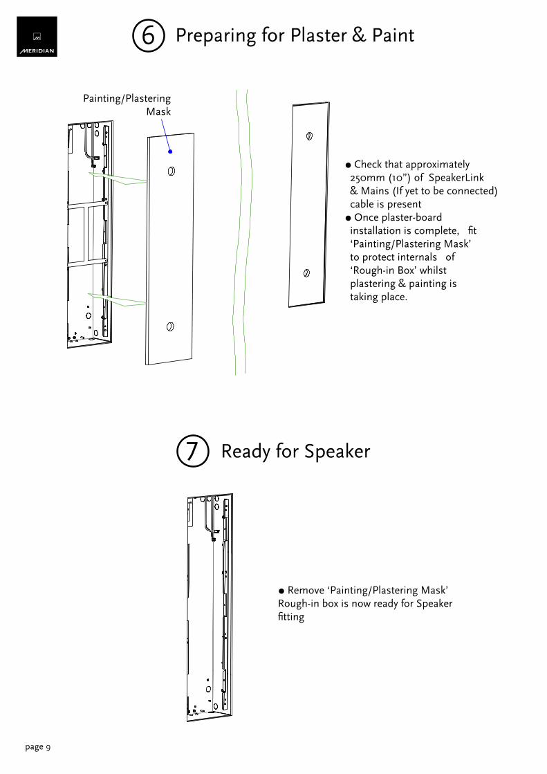
○ Remove ‘Painting/Plastering Mask’ Rough-in box is now ready for Speaker fitting
7
page 9
Ready for Speaker
○ Check that approximately 250mm (10”) of SpeakerLink & Mains (If yet to be connected) cable is present○ Once plaster-board installation is complete, fit ‘Painting/Plastering Mask’ to protect internals of ‘Rough-in Box’ whilst plastering & painting is taking place.
6 Preparing for Plaster & Paint
Painting/PlasteringMask
page 10
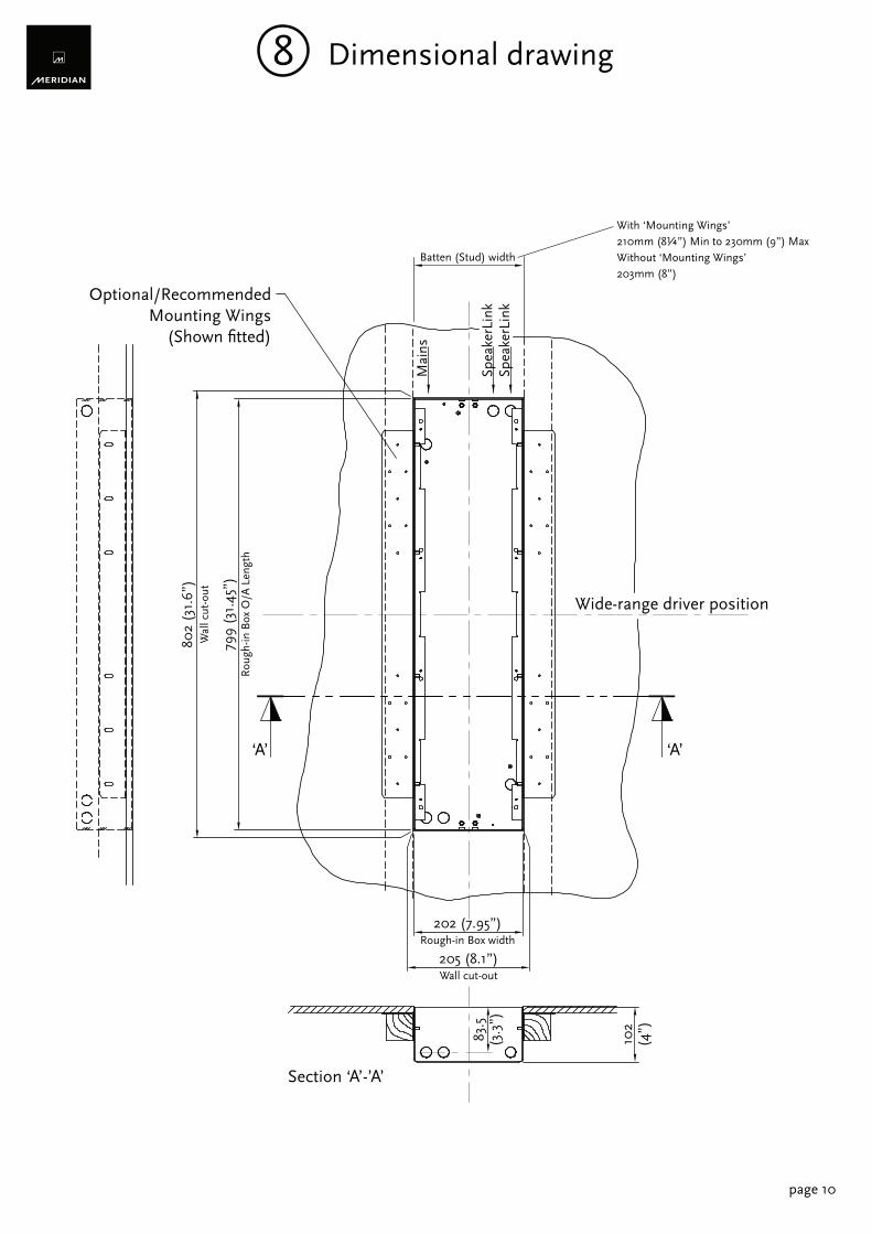
Optional/RecommendedMounting Wings
(Shown fitted)
Wide-range driver position
‘A’‘A’
Section ‘A’-’A’
205 (8.1”)Wall cut-out
202 (7.95”)Rough-in Box width
Batten (Stud) width
802
(31.
6”)
Wal
l cut
-out
799
(31.
45”)
Rou
gh-in
Box
O/A
Len
gth
Spea
kerL
ink
Spea
kerL
ink
Mai
ns
102
(4”)83.5
(3.3
”)
With ‘Mounting Wings’ 210mm (8¼”) Min to 230mm (9”) MaxWithout ‘Mounting Wings’203mm (8”)
8 Dimensional drawing

Meridian RF500Digital Signal Processing Loudspeaker Rough-in Box
Designed and made by Meridian Audio LimitedHuntingdon; England PE29 6YE
Registered Design ® and Copyright © 2012Meridian Audio Ltd.All rights reserved.