Embed Size (px)
Citation preview
© Festo Didactic Inc. 88393-20 33
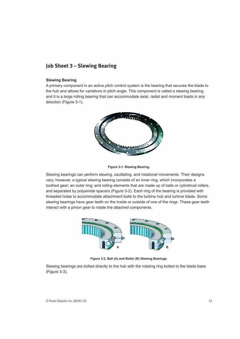
Job Sheet 3 – Slewing Bearing
Slewing Bearing
A primary component in an active pitch control system is the bearing that secures the blade to
the hub and allows for variations in pitch angle. This component is called a slewing bearing,
and it is a large rolling bearing that can accommodate axial, radial and moment loads in any
direction (Figure 3-1).
Figure 3-1. Slewing Bearing.
Slewing bearings can perform slewing, oscillating, and rotational movements. Their designs
vary; however, a typical slewing bearing consists of an inner ring, which incorporates a
toothed gear; an outer ring; and rolling elements that are made up of balls or cylindrical rollers,
and separated by polyamide spacers (Figure 3-2). Each ring of the bearing is provided with
threaded holes to accommodate attachment bolts to the turbine hub and turbine blade. Some
slewing bearings have gear teeth on the inside or outside of one of the rings. These gear teeth
interact with a pinion gear to rotate the attached components.
A B
Figure 3-2. Ball (A) and Roller (B) Slewing Bearings.
Slewing bearings are bolted directly to the hub with the rotating ring bolted to the blade base
(Figure 3-3).

Slewing Bearing
34 © Festo Didactic Inc. 88393-20
Figure 3-3. Slewing Bearings Securing Blades to the Hub.
A slewing bearing and its drive components are included in the hub trainer to assist in the
understanding of the functional characteristics of a slewing bearing in operation on an
actual wind turbine. To facilitate classroom usage, the blade itself is not present; rather, it is
represented by an outline sketch on the front of the trainer. If the blade were present, it would
extend off the back of the trainer, as shown in Figure 3-4.
Figure 3-4. Hydraulic Pitch Hub Trainer with Simulated Blade.

© Festo Didactic Inc. 88393-20 35
Slewing Bearing
Tightening Bolts
Maintenance of a slewing bearing begins with an inspection of the mounting bolts. If any bolts
documents provided by the manufacturer of the bearing. Because of its relatively small cross
section, the slewing bearing cannot bear much direct loading and the mount to which it is
free of any protective oils or coatings that could compromise the integrity of the mating of the
bearing to its mount.
All bolts and nuts should be tightened with an accurate torque wrench (Figure 3-5) in a
Figure 3-5. Common Torque Wrench.
For the torque measurement to be valid, the threads of all bolts and nuts must be coated with a
thin layer of light oil prior to being tightened. To provide uniformly distributed stress across the
slew bearing, the process of bolt tightening should follow a star pattern (Figure 3-6).
Figure 3-6. Typical Star Pattern for Tightening Bolts.

Slewing Bearing
36 © Festo Didactic Inc. 88393-20
A standard four-step tightening process follows:
Step 1: Spanner tight ensuring that 2–3 threads extend above nut.
Figure 3-6.
Step 3: Increase the torque to full torque following the pattern shown in Figure 3-6.
torque.
When loosening bolts, a torque value that is higher than the tightening torque is often required.
This is referred to as breakout torque, and it is necessary due to corrosion and deformations
in the bolt and nut threads. Breakout torque can take up to 2.5 times the input torque to
breakout. The use of penetrating oils or anti-seize products is always recommended when
performing breakout operations.
When bolts become too large and torque stress is too high for common wrenches, a torque
multiplier may be used. A torque multiplier is a small gearbox that increases the torque wrench
force commonly at a ratio of 5 to 1, or a hydraulic bolt tensioner (Figure 3-7). A hydraulically
operated bolt tensioner enables bolts to be tightened accurately without applying torque directly
to the nut and mating threads. To accomplish this, a hydraulic pump is coupled to the tensioner.
to the bolt. This applies a large stretching force on the bolt. The pre-threaded nut can then be
hand tightened until it contacts the face of the slewing bearing. When hydraulic pressure is
released from the tensioner and, therefore, the bolt, an exact tightening force is applied to the
nut-and-bolt combination. When multiple tensioners are used simultaneously, they enable all
bolts to be uniformly preloaded and tightened. Paint pin lines are then applied to each nut, bolt,
and frame to allow for quick inspection on future visits. Loose nuts are given paint pin lines that
Tensioner
Brace
Slew Bearing
Pressurized
Hydraulic Fluid
Hydraulic Body
Skirt
Socket to Hand
Tighten the Nut
Figure 3-7. Hydraulic Tensioner.

© Festo Didactic Inc. 88393-20 37
Slewing Bearing
Seals
The next inspection point is the bearing seals. Slewing bearings commonly have integral seals
strips of a non-reinforced rubber. They seal axially against the side face of the inner or outer
ring, or radially against the cylindrical surface of the inner or outer ring (Figure 3-8).
Figure 3-8. Common Seal Arrangement.
Some bearings may have multiple seals per side. The rubber sealing material is resistant
to most mineral oils and greases, and can operate over a wide range of temperatures. Any
damage should be recorded and the seal should be replaced as soon as possible.
Lubrication
of nine numerical grades based on consistency. As shown in Table 3-1, grades range from
NLGI
Grade
Worked Penetration
After 60 Strokes
at 25 °C (0.1 mm)
Appearance Food Consistency
Analog
000 445-475 cooking oil
00 400-430 applesauce
0 355-385 very soft brown mustard
1 310-340 soft tomato paste
2 265-295 “normal” grease peanut butter
3 220-250 vegetable shortening
4 175-205 frozen yogurt
5 130-160 hard smooth pate
6 85-115 very hard cheddar cheese
Table 3-1. Table of NLGI Grades and Worked Penetration Ranges.

Slewing Bearing
38 © Festo Didactic Inc. 88393-20
through 4 are often used in rolling contact bearings, where grade 2 is the most common.
rating, mixed with a lithium soap thickener and extreme pressure additives. Re-lubrication of a
customized slewing bearing depends on the needs of the application.
3-9). Auto lubrication can be accomplished via a pressurized can or a more complex piped
pumping system.
Figure 3-9. Grease Port with Fitting and Auto Lubricator.
Wind turbines also employ automatic lubrication systems to grease slewing bearings. These
automatic systems can simply be an attached bottle of grease and they provide repeated
greasing between regular maintenance visits.
The hydraulic pitch hub trainer incorporates a system that allows the use of either a manual

© Festo Didactic Inc. 88393-20 39
Slewing Bearing
A
B
C
Figure 3-10. Hub Lubrication System.
to purge the grease contained in the lubricator (C). For training purposes, this cap should be

© Festo Didactic Inc. 88393-20 41
Slewing Bearing
OBJECTIVE
In this job, you will become familiar with the basic principles of slewing bearing
lubrication.
EQUIPMENT REQUIRED
Refer to the Equipment Utilization Chart in Appendix A to obtain the list of equipment
required for this job.
SAFETY PROCEDURES
Before proceeding with this job, complete the following checklist.
You are wearing safety glasses.
You are wearing safety shoes.
You are not wearing anything that might get caught such as a tie, jewelry, or
loose clothes.
If your hair is long, tie it out of the way.
The working area is clean and free of oil.
Your sleeves are rolled up.
Instructor initials:
PROCEDURE
Basic Setup
Lockout/Tagout
Verify that the system has been locked out according to the Lockout/
Begin
Remove the grease plug (C) as shown in Figure 3-11.

Slewing Bearing
42 © Festo Didactic Inc. 88393-20
C
Figure 3-11. Hub Lubrication System.
3-12.
B
Figure 3-12. Grease Fitting B.
Slowly apply a small amount of grease until grease comes out of the
grease plug (C) shown in Figure 3-13.

© Festo Didactic Inc. 88393-20 43
Slewing Bearing
C
Figure 3-13. Plug C.
NOTE :
could result.
Replace the grease plug (C).
Figure 3-14.
A
Figure 3-14. Grease Fitting A.

Slewing Bearing
44 © Festo Didactic Inc. 88393-20
NOTE:
the pump unit. with the piston o-rings.
Remove the grease plug (C).
Remove the top cap of the lubricator as shown in Figure 3-15.
Cap
Figure 3-15. Lubricator Cap.
Ensure that all dip switches are set to the off position as shown in
Figure 3-16.
Figure 3-16. Auto Lubricator with Cap Removed.

© Festo Didactic Inc. 88393-20 45
Slewing Bearing
With a rag or wipe at the ready, set the dip switch 7 (purge) to the On
position.
Once the lubricator starts to dispense grease (this takes approximately
1 minute or less), set dip switch 7 to the Off position.
The lubricator dispenses grease for approximately 1 minute and then
stops.
NOTE:
shut down due to a low ambient temperature of 15° F (-9.44° C). Switches
1–5 control the number of pump stokes and the time period over which they
are delivered (15 days, 1 month, 2 months, etc).
Wipe any grease away and replace plug C.
Lockout/Tagout
Review Questions
1. How is a slewing bearing used in a pitch control system?

Slewing Bearing
46 © Festo Didactic Inc. 88393-20
Name: _________________________________ Date: ______________________
Instructor approval: ___________________________________________________
2. Which item carries the bulk of the force loading on the blade: the slewing bearing
or its mount? Explain.
3. Why are slewing bearing bolts tightened in a star pattern?
4. Where is automated lubrication commonly used in a pitch control system?
5.
table contain and what is the basis for the grading?