Embed Size (px)
Citation preview

1
sc300680_681010514
Rotonivo ®
Series RN 3000RN 4000RN 6000
Instruction manual

2
UWT GmbHWestendstraße 5 Tel.: +49 (0)831 57123-0 Internet:www.uwt.deD-87488 Betzigau Fax: +49 (0)831 76879 E-Mail: [email protected]
/ ATEX 1/2D / IEC-Ex t IIIC / GOST-R / RTN
Scope of this instruction manual:
Types RN 3001 / 3002 / 3003 / 3004 / 3005RN 4001RN 6001 / 6002 / 6003 / 6004
Approvals CE

3
ATEX / IEC-Ex - Notes Page 39
CE-Declaration of Conformity Page 44
Table of Contents
Safety / Warning Notes Page 4
Fields of application Page 4
Technical Data Page 5
Application Page 19
Installation Page 26
Electrical connection Page 29
Switching logic Page 34
Settings Page 38
Maintenance Page 38

4
Safety /warning notes
Installation, maintenance and commissioning may be accomplished only by qualified technical personnel.
For terminal connection of the device, the local regulations or VDE 0100 (Regulations of German electrotechnical Engineers) must be observed.
Switch off the supply voltage before opening the device.
All field wirings must have insulation suitable for at least 250V AC. The temperature rating must be at least 90°C (194°F).
In the case of handling by untrained personnel or handling malpractice, the safety of the device cannot be guaranteed.
Fields of application
Level limit switch for point level limit detection in bulk materials.Applicable as full -, demand - and empty detector.

5
82mm(3.22“)
97mm(3.82“) 36mm
(1.41“)
104m
m(4
.1")
RN 3000
RN 4000
Ø120mm(Ø 4.72“)
135mm(5.31“)
125m
m(4
.92“
)
RN 6000
Technical Data
Housing

6
Ø 33mm(Ø 1.3“) A
RN 3001RN 3002RN 3004
RN 6001RN 6002RN 6004
°C
Temperature extended shaft
Dimension AA = 0mm
(0“)A = 200mm
(7.87“)A = 300mm
(11.8“)A = 400mm
(15.7“)
80°C(176°F)
150/250°C(302/482°F)
350°C(662°F)
600°C(1112°F)

7
A
°C
Ø55/60mm(Ø2.16/2.36“)
RN 3003
RN 6003
Temperature extended shaft
Dimension AA = 10mm
(0.39“)A = 75mm
(2.95“)A = 210mm
(8.26“)
80°C(176°F)
80°C(176°F)
150/250°C(302/482°F)
0,8bar (11.6psi)5/10bar
(73/145psi)0,8/5/10bar
(11.6/73/145psi)

8
Ø10mm(Ø0.39“)
L
RN 3001RN 4001RN 6001
L = 70mm … 1500mm (2.75“ … 59“)
2.00
0mm
(78.
7“)
300
... 1
.000
mm
(11.
8 ...
39.
37“)
Ø8mm(Ø0.31“)
1.43
01 (3
04) /
1.4
305
(303
)
1.43
01 (3
04) /
1.4
305
(303
)
Extension
Rope extension Pendulum shaft
Material according to order data
Material according to order data

9
L
Ø33mm(Ø1.3“)
Ø10mm(Ø0.39“)
RN 3002RN 6002
L = 250mm … 4000mm (9.84“ … 158“)
Extension
Material according to order data
Material according to order data

10
Ø8mm(Ø0.31“)
Ø8mm(Ø0.31“)Ø10mm
(Ø0.39“)Ø10mm(Ø0.39“)
L = 500mm … 10.000mm(19.68“...393.7“)
max. 4 kN max. 28 kN
LL
1.43
01 (3
04) /
1.4
305
(303
)
Extension
RN 3002-RopeRN 6002-Rope
Material according to order data
Material according to order data

11
RN 3003RN 6003
Ø55/60mm(Ø2,16/2.36“)
1.4305 (303)
L = 125mm … 300mm (4.92“...11.81“)
A
B
A B
139mm (5.47")187mm (7.28")
50mm (1.97")98mm (3.9")
L
Extension
Material according to order data

12
RN 3004RN 6004
Ø33mm(Ø1.3“)
Ø10mm(Ø0.39“)
LL = 150mm … 300mm (5.9“...11.81“)
RN 300597x82mm(3.82x3.22“)
87m
m(3
.43“
)
200mm (7.87“)
90m
m(3
.5“)
1.4305 (303)
1.4301 (304)
Extension
Material according to order data
Material according to order data
Material according to order data

13
1.4301 (304) / 1.4404 (316L)
A B50mm (1.97“) 98mm (3.86“)50mm (1.97“) 150mm (5.9“)50mm (1.97“) 250mm (9.84“)98mm (3.86“) 98mm (3.86“)98mm (3.86“) 150mm (5.9“)98mm (3.86“) 250mm (9.84“)
1.4301 (304) / 1.4404 (316L)
Measuring vane
Rectangular vane
Notched

14
1.4301 (304)/1.4404 (316L)
1.4301 (304)/1.4404 (316L)
98mm (3.86“)
98mm (3.86“)
106mm (4.17“)
40m
m(1
.57“
)
35m
m(1
.38“
)
28m
m(1
.1“)
1.4301 (304)/1.4404 (316L)
77mm (3.03“)
26m
m(1
.02“
)
1.4301 (304)/1.4404 (316L)
Measuring vane
Boot shaped vane
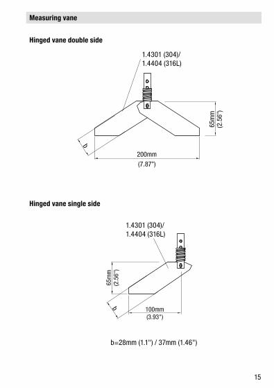
15
b=28mm (1.1") / 37mm (1.46")
1.4301 (304)/1.4404 (316L)
1.4301 (304)/1.4404 (316L)
Measuring vane
Hinged vane double side
Hinged vane single side

16
150mm (5.91“)
27m
m(1
.06“
)
Measuring vane
Universal vane
Rubber vane
Plastic PP
17
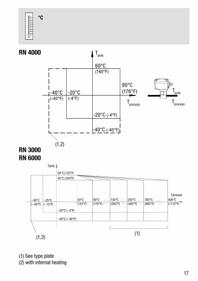
°C
RN 4000 Tamb
60°C(140°F)
-20°C(-4°F)
80°C(176°F)
-20°C (-4°F)
TprocessTprocess
Tamb
-40°C (-40°F)
-40°C(-40°F)
(1,2)RN 3000RN 6000
(1,2)(1)
(1) See type plate(2) with internal heating

18
RN 3000 / RN 6000 min. -0,9bar (-13.1psi) (1) max. 0,8 / 5 / 10bar (11.6 / 73 / 145psi)
RN 4000 min. -0,9bar (-13.1psi) max. 0,8bar (11.6psi)
(1) See type plate

19
RN 3001 /RN 4001 / RN 6001
L max.
600mm(15.24“)
300mm(7.62”)
150mm(5.9”)
150mm(5.9“)
1 2
3
4
5
(1)
L
Installation Orientation
(1) Protective angle (canopy) in case of high mechanical load

20
RN 3001 /RN 4001 / RN 6001
max. 400N
max.1,5kN
Pendulum shaft Rope extension

21
RN 3002 / RN 6002
(3)
(2)
L max.
3.000mm (118.1“)
4000mm (158”)
1 2
max. 10°
L
(2)(3)
Mechanical supportIncline installation with option 32 (bearing at tube end)

22
L
min. 500mm (19.68”)
max. 10.000mm (394”)
1 2
L
(4)max. 4kN / 28kN
(4)
(4)
RN 3002-Rope / RN 6002-Rope
(4) Max. pulling force, see type plate

23
RN 3003 / RN 6003
L max.
300mm (11.81“)
L

24
RN 3004 / RN 6004
L
L max.
300mm (11.81“)

25
RN 3005
Loading bellow

26
Assembly
Example: Insertion of the hinged vane in a long socket
Fixing / Sealing
Spring
Teflon gasket or flat gasket
Sealing

27
(1) (2) (3) (4)
100Nm
Fixing EHEDG
(1)(2)(3)(4)
Certified welding sleeve prescribedMetal-metal support gap-freeTeflon tapeWelding (observe hygiene guidelines)

28
Alignment
Ingress protection IP 66
Option: Weather protection cover
for Ex only approved for Zone 22

29
RN 3000RN 4000
RN 6000
8 7 6 5 1 1 2 PE
7 6 5 4 1 2
8 9 10
Electrical connection
Terminals according to selected version

30
1 2 PE
RN 3000/4000: max. 1,5mm² (AWG16)
RN 6000: max. 4mm² (AWG12)
PE PE
L N 24/48/115/230V ±10% (1), 50/60Hz max. 4VA+ - 24V DC ±15% (1) , max. 2,5W
+ - 24V DC ±15% (1) , max. 4WL N 22...230V ±10% (1) , 50/60Hz, max. 10VA
RN 3000RN 4000
RN 6000
(2)
max. 10A
Power supply
(1)(2)
including 10% from EN 61010see type plate

31
24V DC ±15% (1), max. 0,6A
+ - PE
Version PNP
(1) including 10% from EN 61010

32
8 9 10 7 6 5
DPDT
max.10A
max.10A
RN 3000/4000:max. 250V AC, 2A, 500VA (cosj = 1)max. 300V DC, 2A, 60W
RN 6000:max. 250V AC, 5A (1)
max. 300V DC, 4A (1)
RN 3000/4000: max. 1,5mm² (AWG16)
RN 6000: max. 4mm² (AWG12)
Signal output
(1) not inductive
33
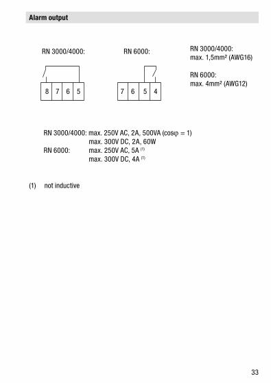
8 7 6 5 7 6 5 4
RN 3000/4000: max. 250V AC, 2A, 500VA (cosj = 1) max. 300V DC, 2A, 60WRN 6000: max. 250V AC, 5A (1)
max. 300V DC, 4A (1)
RN 3000/4000: max. 1,5mm² (AWG16)
RN 6000: max. 4mm² (AWG12)
RN 3000/4000: RN 6000:
Alarm output
(1) not inductive

34
8 9 10
7 6 5
8 9 10
7 6 5
Signal output without FSL/FSH
Switching logic

35
FSL FSHRN 3000/4000:
RN 6000:
FSL
FSH
Signal output with FSL/FSH
gelb(1) grün(2)
grün(2) gelb(1) (1), (2) 37

36
RN 3000RN 4000
RN 6000
Signal output delay

37
8 7 6 5
8 7 6 5
7 6 5 4
7 6 5 4
RN 3000/4000: RN 6000:
Alarm outputVersion with rotation control
No error
Error
(1)(2)
yellowgreen
red

38
(1)
(3)(2) (4)
RN 3000RN 4000
RN 6000
Setting
Setting of the spring force
(1)(2)(3)(4)
Springlight: for light materialcentral: universalstrong: for very sticky material
Maintenance
Normally not necessary

-0,2...+0,1bar (-2.9…+1.45psi)
RN 3001 - 3004RN 4000RN 6000
(1) 2D(2) Db(3) 21
(1) 1D(2) Da(3) 20
(1), (2), (3) 40
39
ATEX II 1/2 D + IEC-Ex t IIC
Notes
Permitted relative pressure
Zone borders

RN 3005
(1) 2D(2) Db(3) 21
(1) 1D(2) Da(3) 20
40
Zone borders
(1) Category ATEX (2) EPL (IEC-Ex) (3) Zone

21 20
30°C (86°F) 50°C (122°F)90°C (194°F)
120°C (248°F) (4)
40°C (104°F) 60°C (140°F)100°C (212°F)
120°C (248°F) (4)
50°C (122°F) 70°C (158°F)110°C (230°F)
120°C (248°F) (4)
50°C (122°F) 80°C (176°F) 120°C (248°F)60°C (140°F) 80°C (176°F) 120°C (248°F)
50°C (122°F)
90°C (194°F)100°C (212°F)110°C (230°F)120°C (248°F)130°C (266°F)140° C (284°F)150° C (302°F)160° C (320°F)170° C (338°F)180° C (356°F)190° C (374°F)200° C (392°F)210° C (410°F)220° C (428°F)230° C (446°F)240° C (464°F)250° C (482°F)
120°C (248°F)120°C (248°F)120°C (248°F)120°C (248°F)130°C (266°F)140° C (284°F)150° C (302°F)160° C (320°F)170° C (338°F)180° C (356°F)190° C (374°F)200° C (392°F)210° C (410°F)220° C (428°F)230° C (446°F)240° C (464°F)250° C (482°F)
T
21
20
21
20
41
Ambient temperature max. Oberflächentemperatur
(4) When using the electronic "universal voltage".
Zone Zone
Zone
Zone
Zone
Zone
RN 3000RN 4000
RN 6000
(1) (1)
RN 3000RN 4000
RN 6000
(2) (2)
42
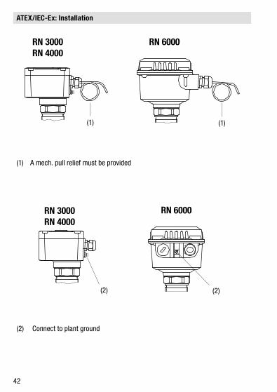
ATEX/IEC-Ex: Installation
(1) A mech. pull relief must be provided
(2) Connect to plant ground

43
ATEX / IEC-Ex: Further Remarks
For installation and field wiring the respectively valid installation regulations of the respective country must be observed.
Commissioning only with closed lid.
Do not remove the lid (cover) while circuits are alive.
Before opening the lid take care, that no dust deposits or whirlings are present.
The installation has to be done in a way, that mechanical friction or impact does not cause sparks between the aluminium enclosure and steel.
For process temperatures over 230°C the delivered sealings of the flanges and of the sliding sleeve must be checked regulary for good order and condition.
Cable Glands:
Installation according to the regulations of the country, where the product is installed.Not used entries have to be closed with blanking elements certified for this purpose.Where applicable the factory provided parts must be used.A strain relief must be provided for the field wiring cables, when the device is installed with the factoryprovided cable glands.The diameter of the field wiring cable must match to the clamping range of the cable clamp.If other than the factory provided parts are used, following must be ensured:The parts must have an approval adequate to the approval of the level sensor (certificate and type of protection).The approved temperature range must be from the min. ambient temperature of the level sensor to the max. ambient temperature of the level sensor increased by 10K. The parts must be mounted according to the instructions of the supplier.

44
EC – Declaration of conformity
Manufacturer UWT-GmbH, 87488 Betzigau, Westendstr. 5
Type Level Limit Switch
Series RN 3000/ RN 4000/ RN 6000
2006/95/EC
Applied standards: EN 61 010-1
2004/108/EC
Applied standards: EN 61 326
94/9/EC (optional)
EC-Type Examination Certificate:
BVS 11 ATEX E 055XDEKRA EXAM GmbHID number: 0158
Applied standards: EN 60079-0EN 60079-31
Note: Units, which are manufactured according to the directive 94/9/EC are respectively marked on the nameplate. Units without this marking are not approved for use in Hazardous Areas (explosive atmospheres).
2011/65/EU RoHS
We hereby confirm that the above-mentioned unit corresponds with the essential safety targets which are fixed in the above mentioned directives.
Signee information: Dipl. Ing. (FH) A. Haug, Technical Manager Date: 03/2014 Signature: