Embed Size (px)
Citation preview
Seite 1 von 20l:\$ka\proj125\TechSpecFR125MAX-2003/Technical-regulation_CIK_2003.doc
APPROVED
ROTAX MAX Challenge Technical Regulations 2003(Version 03.03.2003)
1. Categories:
Karts used in the ROTAX MAX CHALLENGE(RMC), ROTAX MAX CHALLENGE GRANDFINAL(RMCGF) and ROTAX MAX CHALLENGE EVENTS (RMCE) are divided into the followinggroups:
• ROTAX FR 125 Mini MAX, cyl. Capacity 125 cc• ROTAX FR 125 Junior MAX, cyl. Capacity 125 cc• ROTAX FR 125 MAX, cyl. Capacity 125 cc• ROTAX 125 MAX DD2, cyl. Capacity 125 cc, 2-speed
2. Kart:
2.1. Chassis:
Any chassis sanctioned by an authorized ROTAX distributor, for 125 MAX DD2 the chassismust be built according to CIK-FIA 2003 regulations and sanctioned by Bombardier Rotax.Max diameter for chassis tubing 32,0 mm. Round tubing only.Rear axle diameter maximum 50,0 mm, wall thickness according to CIK-FIA rulesAt the RMC Grand finals only chassis are allowed which are built according to CIK rules .No front brakes allowed (except category 125 MAX DD2)
2.2. Bodywork:
In accordance with regulations of national Federation or CIK-FIA.At the RMCGF only bodywork is allowed which is homologated according to CIK-FIA homologation regulations.
For category 125 MAX DD2 only CIK-FIA 2003 homologated bodywork is allowed. Additionallythe ROTAX rear fender system (with integrated rear tyre protection) must be used.

Seite 2 von 20l:\$ka\proj125\TechSpecFR125MAX-2003/Technical-regulation_CIK_2003.doc
2.3. Tyres:
The only tires allowed in races of a national or regional RMC are:
Slick tires: Bridgestone Type: YGKFront: 4.5 x 10.0 -5 Rear: 7.1 x 11.0 –5
Wet tires: Bridgestone Type: YGRFront: 4.0 x 10.0 -5 Rear: 6.0 x 11.0 –5
Strictly no modifications or tire treatment allowed.
2.4. Composite materials:
Composite materials (carbonfibre etc) are banned, except for the seat.
2.5. Petrol:
Unleaded commercial quality from petrol station, max. 98 octane
2.6. Amount of equipment:
For each race event: max. 1 chassis, max. 2 engines, 1 set of slick tires, 1 set ofas well as 1 front and 1 rear spare tire are allowed.
Material used in qualifying must be used at the races (excemption: tires).
2.7. Data acquisition:
Data acquisition devices for recording and displaying of data limited to engine rpm,maximum rpm, coolant temperature, lap times and engine hours.
3. Safety of equipment:
For RMCGF and RMCE article 3 of CIK-FIA technical regulations apply.For RMC overalls , helmets, kart shoes, gloves and other kind of driver protection must complywith regulation of ASN in which RMC is organized.
4. Engines
At all RMC, RMCGF and RMCE races only Rotax kart engines which have been checkedaccording to the procedure below are legal to be used:
Each engine is delivered with its own engine passport.Only “Authorized ROTAX Distributors” and “Authorized ROTAX Service Centers” are allowedto seal engines after carefully checking the engine according to the „Technical Specification
Seite 3 von 20l:\$ka\proj125\TechSpecFR125MAX-2003/Technical-regulation_CIK_2003.doc
for the ROTAX FR 125 MAX“ / “Technical Specification of ROTAX engine type 125 MAXDD2” engine (see item 4.1 and 4.2)Special ROTAX seals (black anodized aluminium seal with „ROTAX“ logo and a 6 digitnumber) with a steel cable must be used.At scrutineering the driver has to present the engine with undamaged seal and the enginepassport, showing the matching engine serial number, seal number, stamp and signature ofthe company which sealed the engine.This procedure helps to reduce scrutineering times at races. Nevertheless it is possible to open and recheck the engines by scrutineers before or after the race in case of a protest and reseal the engine after checking it step by step by staff of the “Authorised ROTAX Service Center or Distributor” according to the „Technical Specification“.
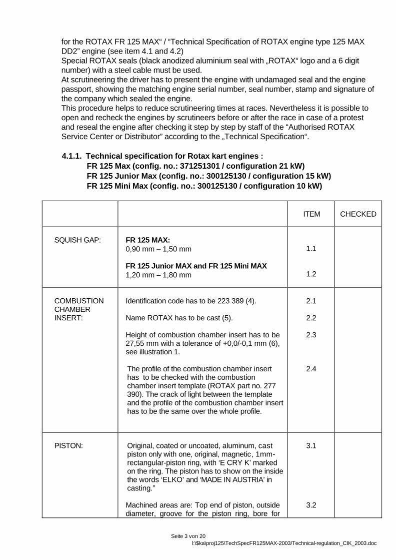
4.1.1. Technical specification for Rotax kart engines : FR 125 Max (config. no.: 371251301 / configuration 21 kW) FR 125 Junior Max (config. no.: 300125130 / configuration 15 kW) FR 125 Mini Max (config. no.: 300125130 / configuration 10 kW)
ITEM CHECKED
SQUISH GAP: FR 125 MAX:0,90 mm – 1,50 mm
FR 125 Junior MAX and FR 125 Mini MAX1,20 mm – 1,80 mm
1.1
1.2
COMBUSTIONCHAMBERINSERT:
Identification code has to be 223 389 (4).
Name ROTAX has to be cast (5).
Height of combustion chamber insert has to be27,55 mm with a tolerance of +0,0/-0,1 mm (6),see illustration 1.
The profile of the combustion chamber inserthas to be checked with the combustionchamber insert template (ROTAX part no. 277390). The crack of light between the templateand the profile of the combustion chamber inserthas to be the same over the whole profile.
2.1
2.2
2.3
2.4
PISTON: Original, coated or uncoated, aluminum, castpiston only with one, original, magnetic, 1mm-rectangular-piston ring, with ‘E CRY K’ markedon the ring. The piston has to show on the insidethe words ‘ELKO’ and ‘MADE IN AUSTRIA’ incasting.”
Machined areas are: Top end of piston, outsidediameter, groove for the piston ring, bore for
3.1
3.2

Seite 4 von 20l:\$ka\proj125\TechSpecFR125MAX-2003/Technical-regulation_CIK_2003.doc
piston pin, inside diameter at bottom end ofpiston. All other surfaces are not machined andhave cast surface.

Seite 5 von 20l:\$ka\proj125\TechSpecFR125MAX-2003/Technical-regulation_CIK_2003.doc
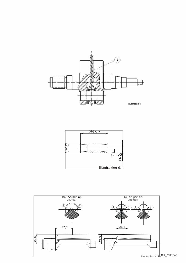
GUDGEON PIN Gudgeon pin has to be made out of magneticsteel.Must be as per illustration 4.1
4.1
CYLINDER: Light-alloy-cylinder with GILNISIL-plating,configuration with one main exhaust port andpneumatic adjusted exhaust valve (exhaustvalve for configuration FR 125 MAX only)Any re-plating is not allowed.
Maximum bore: 54,035 mm (measured 10 mmabove the exhaust port).
Cylinder has to be marked with ROTAX-Logo(1), see illustration 2.
FR 125 MAX:Cylinder has to be marked with identificationcode. 223 997 (2), see illustration 2.
FR 125 Junior MAX and FR 125 Mini MAX:Cylinder has to be marked with identificationcode. 223 999 (2), see illustration 2.
Height of cylinder has to be 87 mm with atolerance of –0,05/+0,1 mm (3),see illustration 3.
All ports and passages are cast finish exceptsome pre-existing, factory removal of flashingfrom inlet and exhaust port and passages. Allports have chamfered edges to prevent ringsnagging. Any additional machining is notpermitted.”
5.1
5.2
5.3
5.4
5.4
5.5
5.6
EXHAUSTPOWERVALVE
Configuration FR 125 MAX only!As supplied by the manufacturer with nomodifications allowed. Compression springmust be fitted.
7.1
CRANKSHAFT: Stroke: 54,5mm ± 0,1 mm
Con rod (7) has to show forged number ”213”or “ 365” on shaft (see ill. no. 4)
Shaft of con rod is not machined (copperplated). Grinding or polishing of shaft of con rodis not permitted.
8.1
8.2
8.3

Seite 6 von 20l:\$ka\proj125\TechSpecFR125MAX-2003/Technical-regulation_CIK_2003.doc
BALANCE SHAFT Balance shaft must be installed and operational.
Different configurations of part no. 237 945 and237 949 are legal (see ill. no. 4.2)
Surface (1) is not machined and must be castsurface (see ill. no. 4.2).
Measurement from centre of balance shaft toouter diameter of fly weight of balance shaft at adefined length must not be lower than specified(see ill. no. 4.2).
The minimum weight of the dry balance shaftmust not be lower than355 grams for balance shaft ROTAX part no.237 945 and255 grams for balance shaft ROTAX part no.237 949
9.1
9.2
9.3
9.4
9.5
CRANKCASE As supplied by the manufacturer. Nogrinding/polishing is permitted in the two maintransfer passages.
10.1
IGNITION UNIT: DENSO digital battery ignition, variable ignitiontiming, no adjustment necessary and possible.Race officials may request at any time thatthe competitor replace the ignition coil with anew unit, provided by race administration.
The casing of the ignition coil has to showfollowing castings "129000 -" and "DENSO".The ignition coil must show 3 pins at theterminal.
The ignition coil has to be fixed by means oftwo original silent blocks to the gearbox cover.Only in cases of chassis componentinterference with the original mountinglocation of the ignition coil, a supplementalextension bracket, rigidly constructed andfabricated of solid metal, of minimumdimensions and attached to the original casemounting holes, is permitted for mounting ofthe coil.
Spark plug: DENSO Iridium IW... orNGK BR ... EG
Original battery must be used,FIAMM-GS type FG 20651 or FG 20722 orFGHL 20722 (as soon as available fromROTAX
11.1
11.2
11.3
11.4
11.5

Seite 7 von 20l:\$ka\proj125\TechSpecFR125MAX-2003/Technical-regulation_CIK_2003.doc
Spark plug cap must be marked with"NGK TB05EMA". 11.6
CARBURETOR: DELL’ORTO carburettor
”VHSB 34” cast in the housing of thecarburettor.
”QD” stamped in the housing of the carburettor.
The complete inlet bore in the casing of thecarburettor must show cast surface
Needle jet stamped with ”FN 266”
The carburettor slide must show with size “40”in casting and the bottom end of the slide mustshow cast surface.
Jet needle stamped with ”K27”
Floats are marked with “gr 5.2”
Idle jet is stamped with the digits “30”
Idle jet insert is stamped with the digits “30”
Start jet is stamped with the digits “60”
Settings of the carburetor adjustment screws arefree.
Main jets smaler than size 160 or bigger than200 are not recommended by ROTA
Main jets smaller than size 160 and bigger thansize 200 are legal also if they are not availablefrom ROTAX.
12.1
12.2
12.3
12.4
12.5
12.6
12.7
12.8
12.9
12.10
12.11
12.12
12.13
12.14
FUEL PUMP: MIKUNI diaphragm pump, must be placed onbottom of support bracket for intake silencer
13.1
FUEL FILTER: The original fuel filter (ROTAX part no. 274160) only is allowed to be fitted between the fueltank and the fuel pump. Any non original in linefuel filter has to be fitted between the fuel pumpand the carburettor.
13.2

Seite 8 von 20l:\$ka\proj125\TechSpecFR125MAX-2003/Technical-regulation_CIK_2003.doc
RADIATOR: Single aluminium radiator as shown inillustration 5.
Cooling area: Height = 290 mm, width = 133mm
Thickness of radiator = 32 mm
Place of fixing the radiator is on right side ofengine.
Radiator must be mounted with support bracket(5) and supporting rod (9), see illustration 5
No additional cooling device is allowed.Tape applied to the face of the radiator only isallowed as an air flow control means. All othermeans of air flow control through the radiatorare prohibited.
New radiator mounting which will be introducedtogether with integrated thermostat is legal fromthe date on it is available from ROTAX
14.1
14.2
14.3
14.4
14.5
14.6
14.7
RADIATORCOOLANT
As glycol coolants are not permitted, distilledwater without any additives has to be used.
15.1
CLUTCH: Dry centrifugal clutch, engagement r.p.m.maximum at 3.000 r.p.m.That means, that the kart (without driver) muststart to move latest at an engine speed ofmaximum 3.000 r.p.m.
16.1
INTAKESILENCER:
Intake silencer with integrated, washable aircleaner with all parts as shown at illustration 6,mounted on the support bracket.
If the race is declared a "wet race" the positionand bracing of the intake silencer is free .
Air filter must be installed as shown inillustration 6.
17.1
17.2
17.3
EXHAUSTSYSTEM:
Must be as supplied by ROTAX and cannot bemodified except for the replacement of thesilencer absorption material and the use ofthreaded fasteners in place of the rivets forsecuring the silencer end cap.
Standard exhaust socket must be used.
18.1
18.2

Seite 9 von 20l:\$ka\proj125\TechSpecFR125MAX-2003/Technical-regulation_CIK_2003.doc
Exhaust pipe with after muffler as shown inillustration 7:
length of inlet cone: 592 mm ±5 mm (measuredon outside from beginning of exhaust pipe untilbeginning of cylindrical part).
length of cylindrical part of exhaust pipe:125 mm ±5 mm.
length of end cone: 225 mm, ±5 mm(measurement, see illustration 8).
outside diameter of 180o bent tube:41mm +1,5 mm/–1,0 mm (measured atbeginning and end of bend).
Diameter of hole of end cap of (illustration 7,pos. 3 or 6): 21 mm +/- 0,2 mm.
The expansion chamber and silencer suppliedwith the engine may not be modified, exceptfor the addition of extra elements to furtherreduce noise levels.
18.3
18.4
18.5
18.6
18.7
18.8
18.9
NOISEEMISSIONS:
Noise isolating mat (illustration 7, pos. 3) has tobe replaced by a original ROTAX spare part, ifthe noise emission is exceeding 92 dB (A).
Noise emission measuring procedure:• The measuring place has to be at section of
the track where the engine is operatedunder full load and at a rpm range of 11.000to 12.000 rpm.
• The microphone has to be installed 1 meterabove the level of the track in a rectangularangle to the track.
• The distance between the microphone andthe kart on the ideal line on the track has tobe 7,5 meters.
• The kart has to be operated under full loadat the ideal line on the track.
19.1
RESTRICTORS: For engine configuration FR 125 Mini MAX(10 kW) only!No modification of restrictors allowed!
Intake restrictor - Insert for carburettor flangewith intake-diameter 19,0 +0,0/-0,2 mm.
Exhaust restrictor – Exhaust socket with outlet-diameter 22,0 +0,0/-0,2 mm
20.1
20.2

Seite 10 von 20l:\$ka\proj125\TechSpecFR125MAX-2003/Technical-regulation_CIK_2003.doc
Seite 11 von 20l:\$ka\proj125\TechSpecFR125MAX-2003/Technical-regulation_CIK_2003.doc

Seite 12 von 20l:\$ka\proj125\TechSpecFR125MAX-2003/Technical-regulation_CIK_2003.doc

Seite 13 von 20l:\$ka\proj125\TechSpecFR125MAX-2003/Technical-regulation_CIK_2003.doc

Seite 14 von 20l:\$ka\proj125\TechSpecFR125MAX-2003/Technical-regulation_CIK_2003.doc
4.1.2. Technical specification for Rotax kart engines : 125 Max DD2 (config. no.: 330125100 / configuration 24 kW)
This technical specification should enable the technical commission to verify the original condition ofthe ROTAX engine type 125 MAX DD2 with configuration 24 kW. By checking these figures step bystep the uniformity of the technical basis of the engine can be confirmed. It is up to the organiser ofthe competition which items are used for the respective reglement.
Only genuine ROTAX components that are specifically designed and supplied for the 125 MAX DD2engine are legal, unless otherwise specified.
Neither the engine nor any of its ancillaries may be modified in any way. "Modified" is defined as anychange in form, content or function that represents a condition of difference from that originallydesigned. This is to include the addition and/or omission of parts and/or material from the enginepackage assembly unless specifically allowed within these rules. The adjustment of elementsspecifically designed for that purpose shall not be classified as modifications, i.e. carburetor andexhaust adjustment screws.
Internal additions: no additional material may be added except in the case of engine repairs and shallonly restore the engine or components to original specifications.
• The use of thermal barrier coatings/ceramic coatings on or in the engine and on or in theexhaust system is prohibited.
• The use of anti-friction coatings in or on the engine/engine components is prohibited.
Legal additions: Temperature gauge and tachometer/hour meter, inline fuel filter and catch can,mounting brackets within the limits specified in this document.
“Non-tech items: non-original fasteners, circlips, washers, throttle cable housing, fuel and pulse line(type and size), and battery mounting bracket are allowed unless otherwise specified.”
ITEM CHECKED
SQUISH GAP: 0,90 mm – 1,30 mm 1.1
COMBUSTIONCHAMBERINSERT:
Identification code has to be 223 389 (4).
Name ROTAX has to be cast (5).
Height of combustion chamber insert has to be
2.1
2.2
2.3

Seite 15 von 20l:\$ka\proj125\TechSpecFR125MAX-2003/Technical-regulation_CIK_2003.doc
27,55 mm with a tolerance of +0,0/-0,1 mm (6),see illustration 1.
The profile of the combustion chamber inserthas to be checked with the combustionchamber insert template (ROTAX part no. 277390). The crack of light between the templateand the profile of the combustion chamber inserthas to be the same over the whole profile.
2.4
PISTON: Original, coated or uncoated, aluminum, castpiston only with one, original, magnetic, 1mm-rectangular-piston ring, with ‘E CRY K’ markedon the ring. The piston has to show on the insidethe words ‘ELKO’ and ‘MADE IN AUSTRIA’ incasting.”
Machined areas are: Top end of piston, outsidediameter, groove for the piston ring, bore forpiston pin, inside diameter at bottom end ofpiston. All other surfaces are not machined andhave cast surface.
3.1
3.2
GUDGEON PIN Gudgeon pin has to be made out of magneticsteel.Must be as per illustration 4.1
4.1
CYLINDER: Light-alloy-cylinder with GILNISIL-plating,configuration with one main exhaust port, twoside exhaust ports and pneumatic adjustedexhaust valve.Any re-plating is not allowed.
Maximum bore: 54,035 mm (measured 10 mmabove the exhaust port).
Cylinder has to be marked with ROTAX-Logo(1), see illustration 2.
Cylinder has to be marked with identificationcode. 613 930 (2), see illustration 2.
Height of cylinder has to be 86,7 mm with atolerance of –0,05/+0,1 mm (3)
All ports and passages are cast finish exceptsome pre-existing, factory removal of flashingfrom inlet and exhaust port and passages. Allports have chamfered edges to prevent ringsnagging. Any additional machining is notpermitted.
5.1
5.2
5.3
5.4
5.5
5.6
INLET SYSTEM: Intake manifold is marked with the name 6.1

Seite 16 von 20l:\$ka\proj125\TechSpecFR125MAX-2003/Technical-regulation_CIK_2003.doc
ROTAX and the identification code 267 410.Some factory flash removal may be present atthe junction of the inside contour and thecarburetor stop mounting face. This is amanual trimming operation consisting of asmall corner break of less than 1mm in width.No additional grinding or machining ispermitted.
The reed valve assy is equipped with 2 petalstops and 2 reeds, each having 3 petals.
The thickness of the reeds is 0,6 mm, ±0,08 mm.
6.2
6.3
EXHAUST VALVE As supplied by the manufacturer with nomodifications allowed. Compression springmust be fitted.
7.1
CRANKSHAFT: Stroke: 54,5mm ± 0,1 mm
Con rod (7) has to show forged number “ 365”on shaft.
Shaft of con rod is not machined (copperplated). Grinding or polishing of shaft of con rodis not permitted.
8.1
8.2
8.3
BALANCE DRIVE Balance drive gear must be fitted on crankshaft.
Balance gear must be fitted on primary shaft.
Surface of flyweight on balance gear must notshow any machining.
9.1
9.2
9.3
2-SPEEDGEARBOX
Primary shaft with 19 teeth for 1st gear and 24teeth for 2nd gear.
The ilde gear for 1st gear has to have 81 teeth.
The ilde gear for 2nd gear has to have 77 teeth.
The gears have to be operated by the originalshift paddle on the steering wheel via the twocalbe bowden
10.1
10.2
10.3
10.4
CRANKCASE As supplied by the manufacturer.The two transfer passages are cast finishexcept some pre-existing, factory removal offlashing.No additional grinding/polishing is permitted in
11.1

Seite 17 von 20l:\$ka\proj125\TechSpecFR125MAX-2003/Technical-regulation_CIK_2003.doc
the two main transfer passages.
IGNITION UNIT: DENSO digital battery ignition, variable ignitiontiming, no adjustment necessary and possible.Race officials may request at any time thatthe competitor replace the ignition coil with anew unit, provided by race administration.
The casing of the ignition coil has to showfollowing castings "129000 -" and "DENSO".The ignition coil must show 6 pins at theterminal.
The ignition coil has to be fixed by means oftwo original silent blocks to the crankcase.
Spark plug: DENSO Iridium IW... orNGK BR ... EG
Original battery must be used,FIAMM-GS type FG 20651 or FG 20722 orFGHL 20722 (as soon as available fromROTAX
Spark plug cap must be marked with"NGK TB05EMA".
12.1
12.2
12.3
12.4
12.5
12.6
FUEL PUMP: The original diaphragm pump (out of plasticswith grey or black colour) must fitted by meansof the two original silent blocks to the chassis ofthe kart.
The highest point of the fuel pump may not behigher than 100 mm above the main tube of thechassis.
14.1
14.2
FUEL FILTER: The original fuel filter (ROTAX part no. 274160) only is allowed to be fitted between the fueltank and the fuel pump. Any non original in linefuel filter has to be fitted between the fuel pumpand the carburettor.
15.1
RADIATOR: Single aluminium radiator.
Name “ROTAX” is stamped in the top of theradiator.
Cooling area: Height = 284 mm, width = 202 mm
Thickness of radiator = 32 mm
The radiator must be fitted on the left side of the
16.1
16.2
16.3
16.4
16.5

Seite 18 von 20l:\$ka\proj125\TechSpecFR125MAX-2003/Technical-regulation_CIK_2003.doc
kart beside the seat.
The highest point of the radiator with cap maynot be higher than 400 mm above the main tubeof the kart chassis.
No additional cooling device is allowed.
All other means of air flow control through theradiator are prohibited.
16.6
16.7
16.8
RADIATORCOOLANT
As glycol coolants are not permitted, distilledwater without any additives has to be used.
17.1
CLUTCH: Centrifugal clutch in oil bath, engagementr.p.m. maximum at 4.000 r.p.m.That means, that the kart (without driver) muststart to move latest at an engine speed ofmaximum 4.000 r.p.m.
18.1
INTAKESILENCER:
Intake silencer with integrated, washable airfilter.
The intake silencer case is marked on theinside with the ROTAX part no. 225 012.
The intake silence cover is marked on theinside with the ROTAX part no. 225 022.
The air filter is marked with the ROTAX part no.225 052.
The air filter must be assembled between theintake silencer case and intake silencer coverthat the hole area of the intake silencer case iscovered.
19.1
19.2
19.3
19.4
EXHAUSTSYSTEM:
Must be as supplied by ROTAX and cannot bemodified except for the replacement of thesilencer absorption material and the use ofthreaded fasteners in place of the rivets forsecuring the silencer end cap.
Standard exhaust socket must be used.
The expansion chamber and silencer suppliedwith the engine may not be modified, exceptfor the addition of extra elements to furtherreduce noise levels.
20.1
20.2
20.3
NOISEEMISSIONS:
Noise isolating mat (illustration 7, pos. 3) has tobe replaced by a original ROTAX spare part, if
21.1

Seite 19 von 20l:\$ka\proj125\TechSpecFR125MAX-2003/Technical-regulation_CIK_2003.doc
the noise emission is exceeding 94 dB (A).
Noise emission measuring procedure:• The measuring place has to be at section of
the track where the engine is operatedunder full load and at a rpm range of 11.000to 12.000 rpm.
• The microphone has to be installed 1 meterabove the level of the track in a rectangularangle to the track.
• The distance between the microphone andthe kart on the ideal line on the track has tobe 7,5 meters.
• The kart has to be operated under full loadat the ideal line on the track.

Seite 20 von 20l:\$ka\proj125\TechSpecFR125MAX-2003/Technical-regulation_CIK_2003.doc


![fileMEGA Rübig Rotax Max Micro Rotax Max Mini Rotax Max Junior KZ 2 Masters MEGA Rübig Klasse 6 Rotax Max Senior [MRC / AKC] Klasse 3 Rotax Max DD2 / AKC] Div. V Div. IV Div. Ill](https://img.pdfslide.us/doc/110x75/5e17b05c8d318420da4b756e/rbig-rotax-max-micro-rotax-max-mini-rotax-max-junior-kz-2-masters-mega-rbig.jpg)