Embed Size (px)
Citation preview
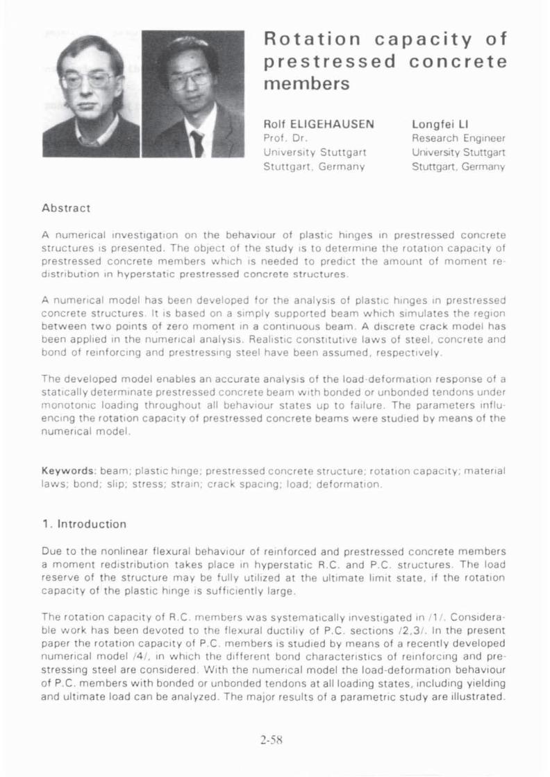
Abst rac t
Rotation capacity of prestressed concrete members
Roll ELiGEHAUS EN Prof Dr. Umverslty Stuttgart
Stuttgart Germany
Longlei LI Research Engineer UniverSIty Stuttgart
Stuttgart. Germany
A numerical investigation on the behaviour of plastic hinges In prestressed concrete structures IS presented. The object of the study IS to determine the rOtation capacity of prestressed concrete members which IS needed to predict the amount of moment fe distribution In hyperstatlc prestressed concre te structures
A numencal model has been developed for the analysIs of plastic hinges In prestressed concrete structures It IS based on a simply supported beam which simulates the region between two POints of zero moment In a continuous beam A discrete craCk model has been applied In the numerIcal analysIs. Realistic conStitutive laws of steel. concrete and bond of reinforcing and prestressing steel have been assumed. respectively
The developed model enables an accurate analysIs of the load deformation response of a statically determinate prestressed concrete beam with bonded or unbonded tendons under monotoniC loading throughout all behaViour states up to failure . The parameters tnflu enelng the rotation capacity of prestressed concrete beams were studied by means of the numerical model
Keyword s. beam. plastic hinge. prestressed conc rete structure. rotallon capacity, material laws. bond. slip, stress; strain. crack spaCing. load. deformatlOn
, . Introduct ion
Due to the nonlinear flexural behavlOur of reinforced and prestressed concrete members a moment redistribution takes place In hyperstatlc A.C . and PC structures The load reserve of the structure may be fully utilized at the ultimate limit state. If the rotation capacity of the plastiC hinge IS suffiCiently large.
The rOtation capacity of A,C members was systematically investigated In , . Considera ble work has been devoted to the flexural ductlhy of P.C. sections /2 .3 /. In the present paper the rotation capacity of PC members IS studied by means of a recently developed numencal model 14 /. In which the different bond characteflstlcs of reinforCing and pre· stressing steel are considered . With the numertcal model the load-deformation behaViour of P.C. members with bonded or unbonded tendons at all loading states. Including Yielding and ultimate load can be analyzed . The malar results of a parametric study are Illustra ted .
2-5/\
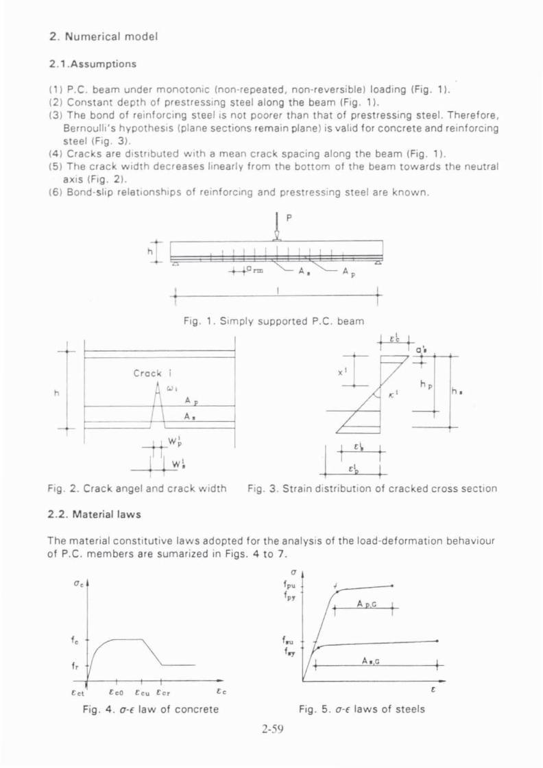
2 . Numerical model
2.1.Assumptions
(1) p.e. beam under monotonic (non-repeated, non-reversible) loading (Fig. 1). (21 Constant depth of prestressing steel along the beam (Fig. 11. (31 The bond of reinforCing steel IS not poorer than that of prestressing steel. Theref ore,
Bernoulli's hypothesIs (plane sections remain plane) IS valid for concrete and reinforcing steel (Fig. 31.
(4) Cracks are dIstributed with a mean crack spacing along the beam (FIg. 11. (51 The crack width decreases linearly from the bottom of the beam towards the neutral
aXIs (Fig. 21. (61 Bond -slip relationships of re in forCing and prestresSing steel are known.
h
p
A. Ap
Fig . 1. Simply supported p.e. beam
Crock i
Ap
I A.
~w~ I I w~
I
I '\
Fig . 2. Crack angel and crack width Fig . 3 . Strain distribution of cracked cross section
2 .2. Material laws
The matenal constitutive laws adopted for the analYSIS of the load·deformation behaviour of P.C. members are sumarized in Figs. 4 to 7.
0,
f,
'd leO leu l or
Fig , 4 , 0·[ law of concrete
o fp•
f"
f~ f.,.
2-59
A p,G
AI,e
, Fig , 5 . a·E laws of steels

Fig. 4 shows the U,-f, relationship for concrete in compression and tension /1 .5/. Fig . 5 illustrates the stress-strain curves for reinforcing and prestressing steel /1,5 ,6/. The curves are definded by a polygone pOint by pOint. Hence. they are suitable for any analytical expression with desired accuracy by means of an increasing number of support points. Figs. 6 and 7 show the bond-slip relationships for reinforcing and prestressing steel respectively /1.5/. The bond stresses near cracks are reduced according to /7/.
Tp.1IM&
5 •. 1 S • .z S • . 3 s. S ,.1 s s p.Z p .3 s,
Fig. 6. Bond-slip law of reinforcing steel Fig . 7. Bond-slip law of prestressing steel
2.3. Compatibility, equilibrium and boundary conditions
A simply supported p.e. beam (Fig . 11 that simulates the region between two points of zero moment in a continous beam is considered for the analysis of the load-deformation behaviour of p.e. members. The beam is assumed to be prestressed with prestressing tendons as well 8S to be reinforced with reinforcing steel . The anchoring of the prestressing steel prevents a displacement of the prestressed reinforcement at the beam ends. The reinforcing steel. however, may slip. Therefore. the following boundary conditions are valid:
s,(O) .s,(1)=0 0 ,,(0) =,,(1) =0 ( 11
The elongations of reinforcing and pres.tressing steel along the beam are related as following:
I I
f[e,(~) -.,..<~))dx-« f e,(~)dx (2)
• • a is a factor which takes into account the different internal lever arms of reinforcing and prestressing steel, respectively. in the cross section. Epd is definded as strain of the prestressing steel at the state of decompression at which the concrete strain at the level of the prestressing steel is E,=O .
The compatibility conditions between concrete and reinforcing steel as well as prestressing steel can be expressed as:
dx,(~) ~ ="(~) -',(x) 0
(3)
For an element between two cracks the following expressions result from integrating equation (3). when the concrete strains are neglected (Fig. 8) .
• • s,(x)-fe,(~)dx.s: 0 s,(~) -[I.,(~)-.",<x)ldx.s~ (4)
• • 2-60

crack 0=
crack 1+1 I I
t.4 1 A; 0~+1 + 01..-'
MI+l
C D~ +O! "-- V ) crack element h
• z~ s~ T,(X) A, 51+ 1 Zl+l , , •
• • z; s~ T,(x) ' A.
si+1 Zl:l
x
Fig . 8. Forces and displacements on crack element
By substituting equation (4) in equation (2) and considering the boundary conditions according to equation (1). the compatibility of elongations of reinforcing and prestressing steel may be transformed to the compatibility of crack widths at the height of the reinforcing and prestressing steel (Figs. 2 and 3) .
For bonded prestressing tendons equation (5) is valid:
N N ~ ,_~ , I L- w,-~ ex w, , ,·1 ,.1
I 'wI w, =ex I
For unbonded prestressing tendons equation (61 is valid:
N
(', -.,.JI = E alw: I.'
with
I h, -x' a =
h -x' ,
(5)
(6)
s.',s,,',sO'·,sfjl' denote the actual slip of reinforcing and prestressing steel at the left or right crack face, respectively. For a beam under symmetric loading the slips of reinforcing and prestressing steel in the crack at midspan are related according to equation (8)
•• •• s'=a's' s. r=s.. spl =s/W ' P' • (8)
The equilibrium equations for reinforcing and prestressing steel in the tensioned region of the cross section can be expressed as following :
Between two cracks (Fig. 8)
(91
In the cracks (Figs. 2, 3 and 8)
EH=O: Z;+Z:-O;-O>O. EM=O : Z;;',+Z:h.-O~,-O:a;+M"O (10)
By substituting x,' as curvature of the cross section K, and x,' as strain of the rainforcing
2-61
steel f; equation (10) may be translated to the following form:
H(x:~'O. M(x:~eO (11 )
The strain distribution of the cracked cross section can be determined by solving equation (11) by iteration.
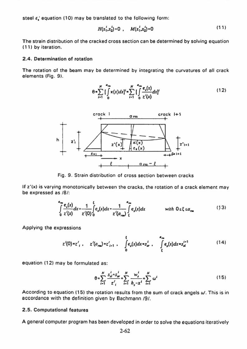
2.4. Determination of rotation
The rotation of the beam may be determined by integrating the curvatures of all crack elements (Fig . 9).
II ... II ...
eeLlJ k(x)d.t)'eLlJ .;(x) d.t)' ,-1 0 ,·1 0:' (x)
(1 2)
crock o~
crock 1+1 1 I
. ..J --
h
1·"·' "(xI ell , +-+-,-1+1
X
f Om-!
Fig. 9 . Strain distribution of cross section between cracks
If z'(x) is varying monotonically between the cracks. the rotation of a crack element may be expressed as /S/:
.~() t .~
J• x 1 J 1 J ...!..-..d.t--- .,(x)d.t+ ',(x)d.t • l '(X) l'(O). l'(a...) t
Applying the expressions
t
• '(0) el',. .'(a...) el' I.' . J .,(x)d.tes~ • •
equation (12) may be formulated as:
II I I N I II 't"' Sol+S. E w, E ' eCL.--e __ e '"
, h' '-1 l I ,.1 ,-X f·'
with 0 ~ ~ sa,.
.~
J .,(x)d.tes~' t
() 3)
( 14)
(1 5)
According to equation OS} the rotation results from the sum of crack angels W. This is in accordance with the definition given by Bachmann /9/.
2.5. Computalional features
A general computer program has been developed in order to solve the equations iteratively
2·62
for symmetrically loaded beams at all loading stages. Any symmetric concrete section with one layer each of reinforcing and prestressing steel in the tension zone of the cross section can be analyzed . The computations are done under deformation control by controlling the strain of concrete . reinforcing· or prestressing steel at midspan, respective· Iy. so that the deformations of the beam under peak load can be obtained.
3 . Verification of the numerical model with test results
The analytical model is suitable for the analysis of P.C. members with bonded or unbonded tendons as well as for the analysis of R.C. members. Various test results of P.C. and R.C. beams 110.11 .12.13.14.1 were analyzed .
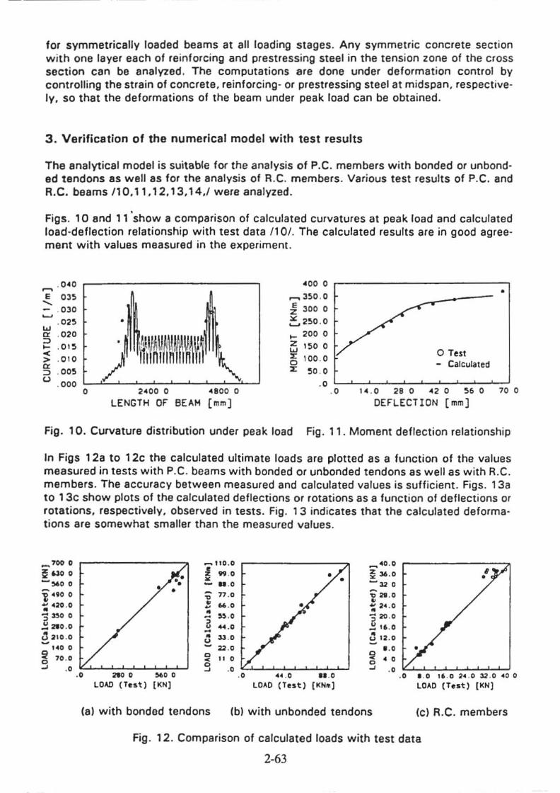
Figs . 10 and 11 'show a comparison of calculated curvatures at peak load and calculated load-deflection relationship with test data 1101. The calculated results are in good agreement with values measured in the experiment.
. 0.40 . 00 0 ~ • E 03> ~ 3S0 .0 ..... :i 300 0 - . 030 ~
=.,2S0 . 0 .02S • w
.... 200 0 '" . 020 :::l
~ 1500 ~ .Ol!l o Test -< '" 100 . 0 > .010 0 - Calculated cr. :::l . 00!l '" ~O . O U . 0 00 .0
0 204 00 0 0411 00 0 . 0 ' 04 . 0 2. 0 <2 0 , . 0 70 0
LENGTH 0, BEAM [mm] OE,LECTION [mm]
Fig. 10. Curvature distribution under peak load Fig. 11 . Moment deflection relationship
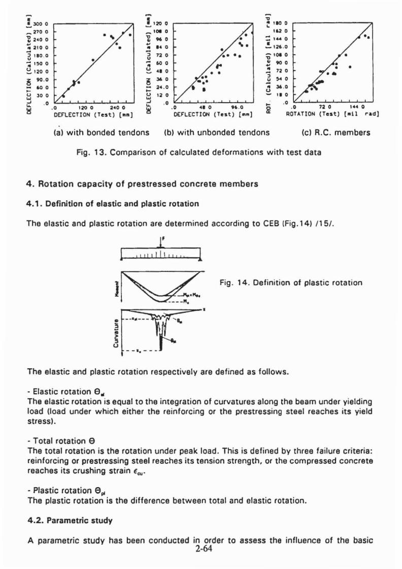
In Figs 12a to 12c the calculated ultimate loads are plotted as a function of the values measured in tests with P.C. beams with bonded or unbanded tendons as well as with R.C. members . The accuracy between measured and calculated values is sufficient. Figs . 138 to 13c show plots of the calculated deflections or rotations as a function of deflections or rotations. respectively, observed in tests. Fig . 13 indicates that the calculated deforma· tions are somewhat smaller than the measured values .
-_. ~~O 0 .... "'00
i ".00
~ "20 .0
'3 ))0 0
~ 210 . 0
~ 210 . 0
uo 0 !iI 70 . 0 0 -' ••
..... HO . O
! .... ~ .... " . 0 -~ n .• • ~ .... • - .,.. , u - .... • ..... u
22 .• 0 " . ~ 0 -' •• •• .... .. .. ••
LO,," (Tut ) IKH]
• •
U .O •• . 0
LOAO (Tnt) ( I< NM)
.... .. 0 . 0
~ » .0 -", . -~ 21 .0 • ~ 2 • . 0
'3 20 •0
~ 1' . 0
~ 12 .0
0 . • !iI •• 0 -' •• ••
•
. . 0 1' . 0 2 • . 0 32 .0 . 00
LOAD (Test) (I<N]
(a) with bonded tendons Ib) with un bonded tendons (c) R.C. members
Fig . 12. Comparison of calculated loads with test data
2-63
-• .!. 300 0 !'2O 0 ..... 101 0
! 110 0 ,----------"
_2'00
~ 4140 0
!; 210 0 -~ 110 . 0
-;; !!lO 0
~ 1200
~ 90 .0
- 600 ~
~ 300
. ... •
• • • "Z .. 0
~
OIl ... 0 a no -;; 60 0 U ••• iii ,..
24 . 0
•• •
• • • .... .- .. ,.
• •
,., . = , ... 0 • ...... 1:lio . O
:; 101 0
!! to 0
.! 72 0
~ )4 0 -OIl 36 . 0 U ".
••
'. • •
it l!j
•• . 0 120 0 240 0 . 0 •• 0 " .0 •• RorAnON
72 0 ..... 0
DEFlECTION (Test ) (Mal O(F'LECTIOH (Tnt) [ -J (Test) [1111 rad)
lal with bonded tendons Ibl with unbonded tendons Icl R.C. members
Fig . 13. Comparison of calculated deformations with test data
4. Rotation capacity of prestressed concrete members
4 .1. Definition of elastic and plastic rotation
The elastic and plastic rotation are determined according to CEe IFig.141 /15/.
I '""£,''" 1 Fig . 14. Definition of plastic rotation
- -I. __ _
The elastic and plastic rotation respectively are defined as follows.
- Elastic rotation 9. The elastic rotation is equal to the integration of curvatures along the beam under yielding load (load under which either the reinforcing or the prestressing steel reaches its yield stressl.
- Total rotation 9 The total rotation is the rotation under peak load. This is defined by three fa ilure criteria : reinforcing or prestressing steel reaches its tension strength, or the compressed concrete reaches its crushing strain Ecu '
- Plastic rotation 9. The plastic rotation is the difference between total and elastic rotation .
4 .2. Parametric study
A parametric stud V has been conducted in order to assess the infiuence of the basic 2-64
parameters governing the rotation capacity of p.e. members.
The numerical constants of material laws 8S well as the geometry of the concrete members are identified in table 1 by reference to the material laws in section 2.2.
Material laws Geometry
Concrete t, = 42 .5 Nlmm' £",= -2 .0'" £~= ·5.0'" 1- 5.0m d=0.6m
Reinforcing 1.., - 500 Nlmm' 1 .. =550 N/mm' A •. r;*"5.0% A EO.51 P=0.55
(=0.5 Steel
Prestressing to. E 1 080 Nlmm' t .. = 1230 Nlmm' A •.• -4.0% g I 1000. I -Steel •
!~] Reinforcing T •. ",,, = 12.0 N/mm' Steel Bond
Prestressing T.,",'" - 6.0 N/mm2 ~ !'oo, !
Steel Bond
Table 1. Material laws and geometry of beams for parametric study
The parameters influencing the rotation capacity of p.e. members may be expressed as material. geometrical and loading parameters. respectively .
• The material parameters afe : 0-( laws of concrete. reinforcing and prestressing steel : bond-slip relationships 01 reinforcing and prestressing steel.
• The geometrical parameters 8re : percentage of tension and compression reinforcement. degree of prestressing. diameter of reinforcing and prestressing steel, slenderness of the beam and mean crack spacing.
• The loading parameters are : prestressing ratio. moment/shear ratio and load distribution over the beam.
Some inlluences on the rotation capacity of p.e. members are presented in the following. Further studies are described elsewhere 14/.
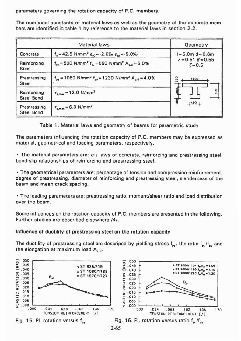
Inlluence of ductility of prestressing steel on the rotation capacity
The ductility of prestressing steel are descriped by yielding stress I". the ratio f • ./I., and the elongation at maximum load Ap•G '
'0 OSoO ~ 04So ..... . 040 e . 03So :: . 030 ~ 025 ~ 020 u OIS ;:: .010 ~ 005
.. ST 835/919 • ST 108011188 o ST 1570/1727
....
0 .050 r--------------, ~ . 045 liST 1080/1134 '_""-1.05 ~ . 040 .ST 1080"'881,..11 .. _"'0 a . 035 "nl08011ltCit./f ... _l .20
:: . 030 ~ . 025 ~ . 020 u .015 ;:: .010 ~ . (l05
it . 000 l....~_~--'-_'-~~_-L.~_~_ . 000 .034 .068 . 102 136 170
TENSION REINFORCEHENT [I)
It .000 '-~-'--~-'-'-~--'-~-'-0 00 . 034 . 068 102 .1 36 170
TENSION REINFORCEMENT (I]
Fig. 15. PI. rotation versus f", Fig. 16. PI. rotation versus ratio I • ./f",
2·65
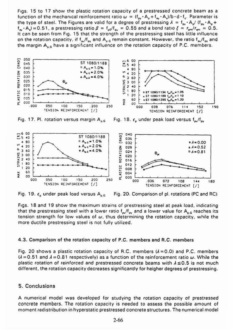
Figs . 15 to 17 show the plastic rotation capacity of a prestressed concrete beam as a function of the mechanical reinforcement ratio w = (fpy. Ap + fry ' A., /b· d· fto Parameter is the type of steel. The Figures are valid for a degree of prestressing A = f .. • A,I If .. • A, + f". A,) = 0 .51 . a prestressing ratio p = f,clf.., = 0.55 and a bond rallo { = T,.,IT_ = 0.5 . It can be seen from Fig . 15 that the strength of the prestressing steel has little influence on the rotation capacity , if '""/fpy and A p G remain constant . However, the ratio fpVlfpy and the margin A p.G have a SIgnificant influence on the rotat ion capacjty of P.C. members .
'0 050 '-------- -,S"T--'''0''8''0-''-'-8--8' ~ 0"5 .... 0 <4 0 O Ao co -l ,O%
~ 035 -A.(;-2 .0% ;: OJD A A.., •• . 0% '! 025 ~ 0 20 u 0 15 ;: 010 ~ ('IO~ ~ 000 ~~~L-~~_~~ ___ ~_~~
. 000 050 t OO 150 . 200 250 T [ ~Sl~ R ( lNrogC[~E~l [ I )
Fig . 17. PI. rotation versus margin AII,G
...... 6 00 ~ 5 oli O
• 80 VI " 20 Q. 3 60 ~ 3 0 0 "< 2 .0 ~ 1 eo II! I 20 • . 0
I~ ST 10eOll 18S o A".co . 1 ,0,," .. A. co" 2.0% -A..co - 4 .O%
~ 00 ~~_L-~~_~~_~~_L-~ 000 0 50 10 0 150 2 00
TENS ION REI NFOACE"ENT [ / )
Fig. 19. €, under peak load versus A,.o
250
~. 00 ~5 '0
• 80 ~. 20 ~ 3 60 ~3 00 :<2 '0 ~ , 80 o IT 10801' 1)4 t,..l1 ... , .OS ~, 20 .. S T 108011 1.0 fJf ... -'10
• 60 • $oT ,000012I' t.fl.,.- 1,20 • 00 • 000 038 07. "' 102 190 TENSI ON AE INrOAC[H[NT [IJ
Fig . 18 . €, under peak load versus f,./f ..
0 0'0 • 0,.
'" .A-O,OO 032
~ 028 ... hO.52 - 02' e. DA-0.81 -• 020 -0 0'.
~ '" u 0'2 - 008 - -~ 00. • It 000
000 . 036 072 108 ... 180 TENSION REINFORCEMENT [I)
Fig . 20. Comparison of pI. rotations (PC and RC)
Figs. 18 and 19 show the maximum stra ins of prestressing steel at peak load , indicating that the prestressing steel with a lower ratio f .. /f .. and a lower value for A..o reaches its tension strength for low values of w. thus determining the rotation capacity. while the more ductile prestressing steel is not fully utilized.
4 .3. Comparison of the rotation capacity of P.C. members and R.C. mambers
Fig. 20 shows a plastic rotation capacity of R.C. members (A =0.0) and P.C. members (A =0.51 and A =0.81 respectively) as a function of the reinforcement ratio w. While the plastic rotation of reinforced and prestressed concrete beams with A sO.5 is not much different. the rotation capacity decreases significantly for heigher degrees of prestressing .
5. Conclusions
A numerical model was developed for studying the rotation capacity of prestressed concrete members. The rotation capacity is needed to assess the possible amount of moment redistribution in hyperstatic prestressed concrete structures . The numerical model
2-66

accepts any type of constitutive material laws, so that all the parameters affecting the rotation capacity of prestressed concrete members can be studied. The predicted results agree sufficiently well for practical purposes with test data.
According to the parametric study the rotation capacity of prestressed concrete beams is influenced by the ductility of the prestressing steel in much the same way as reinforced concrete beams by the ductility of the reinforcing steel. For constant values of the mechanical reinforcement ratio the rotation capacity decreases with increasing degree of prestressing.
References:
III Langer, P.: Verdrehfahigkeit plastizierter Tragwerksbereiche im Stahlbetonbau. Dissertation Universitiit Stuttgart 1987
121 Cohn, M.Z., Riva , P.: Constitutive laws of structrural concrete for application to nonlinear analysis. IABSE Symposium, Delft , August 1987
131 Cohn, M.Z., Riva, P.: Flexural Ductility of Structrural Concrete Sections. PCI Journal,March-April 199 I
141 Eligehausen, R., Li, L. : Schlutlbericht zum Forschungsvorhaben: ·Plastische Gelenke im Spannbetonbau·. Institut fUr Werkstoffe im Bauwesen, Universitat Stuttgart, in Vorbereitung.
151 Kreller, H.: Zum nichtlinearen Trag- und Verformungsverhalten von Stahlbetontragwerken unter Last ~ und Zwangeinwirkung. Dissertation Universitat Stuttgat 1989
161 Dilger, W .: Veranderlichkeit der Biege- und Schubtragfahigkeit bei Stahl betontragwerken und ihr EinfluB auf Schnittkraftverteilung und Traglast bei statischunbestimmter Lagerung. Deutscher AusschuB fUr Stahl bet on H. 179, Berlin: W . Ernst & Sohn 1966
171 Ciampi, v .; Eligehausen, R.; P.; Bertero, V. V.; Popov, E. : Analytical Model for Concrete Anchorages of Reinforcing Bars under generalized Excitations Earthquake Engineering Research Center, Report No. UCBIEERC 82123, University of California, Berkeley 1982
181 Bartsch, J. H. : Taschenbuch mathematischer Formeln. Verlag Harri Deutsch, Thun und Frankfurt/Main, 1990
191 Bachmann, H.: Zur 'llastizitats theoretischen Berechnung statisch unbestimmter Stahlbetonbalken. Dissertation ETH Zurich, 1967
1101 Eibl, J.; Mora , J.; Strautl, P.: AbschluBbericht zum Forschungsvorhaben: ' Momentenrotation und Schubtragfahigkeit im Spannbeton' . Universitat Karlsruhe ,lnstitut fUr Massivbau und Baustofftechnologie, Karlsruhe 1983
II I I Caflisch, R.; Thurlimann, B. ; Biegeversuche an teilweise vorgespannten Beton balken. Bericht Nr. 6504-1, Institut fur Baustatik ETH Zurich 1970
1121 Harajli, M. H., Kanj, M . Y.: Ultimate Flexural Strength of Concrete Members Prestressed with Unbonded Tendons. ACI Structrural Journal, Nov.-Dec . 1991
1131 Tao, X., Du, G.: Ultimate Stress of Unbonded Tendons in Partially Prestressed Concrete Beams. PCI Journal, Nov.·Dec. 1985
1141 Clarke, J. L., Beeby, A. W .: The ductility of reinforcement and its influence on the rotation capacity of concrete sections. British Cement Association, Wexham Springs, Slough SL3 6PL, nov. 1990
1151 CEB - Bulletin d'information No, 30, 1969
2-67