Embed Size (px)
Citation preview

What’s Inside
Ingersoll Rand 1100 Steam Turbine Repair 2
Harmonic Response Stress Analysis of Blades in Resonance
3
Centrifugal Compressors 4
RMS Staff Holiday Fun 5
Employee Highlight 6
New Employees 7
FCC Power Recovery Train Roundtable 7
Winter Driving Safety Tips 8
RMS Steam Turbine Capabilities 9
RMS Axial Compressor Capabilities 10
RMS Word Power 11
Pipeline Compressor Journal Bearing Failure B/C
VOLUME 11, ISSUE 4 October - December 2015 2015
The Finish Line Phone 484-821-0702 Fax 484-821-0710 www.rotatingmachinery.com
������
RMS FIELD SERVICE AND SHOP OPERATIONS By Charles (Chot) Smith
RMS IMPORTANT NUMBERS
HOUSTON SALES OFFICE:
Kurt Diekroeger 281-340-8520 (O) 713-898-1015 (C)
David Cummings 281-340-2056 (O) 832-444-0592 (C)
TENNESSEE SALES
OFFICE: Mike Spangler
865-981-9831 (O) 484-896-8438 (C)
CORPORATE OFFICE:
Bill Velekei 484-821-0702 (O) 484-896-8569 (C)
RMS field service operations had a record year in 2015 realizing a 60% growth in business and also enter 2016 with a nice backlog. The year ends with the start of a challenging project for an US utility company in Florida. RMS has been contracted to remove, refurbish, and reinstall two Worthington 224 Expanders formerly used as power generation “peakers”. These units will be repurposed and used for “Black Start” emergencies in the future. The project came with some challenges due to the weight and size of the equipment to be removed and transported to our shop in
PA. We have completed the removal process, both units have been received in our service center, and the disassembly and inspection process has been started. The refurbished units are scheduled to be completed early in April.
ROTATING MACHINERY SERVICES, INC.
������ Page 2 ROTATING MACHINERY SERVICES, INC.
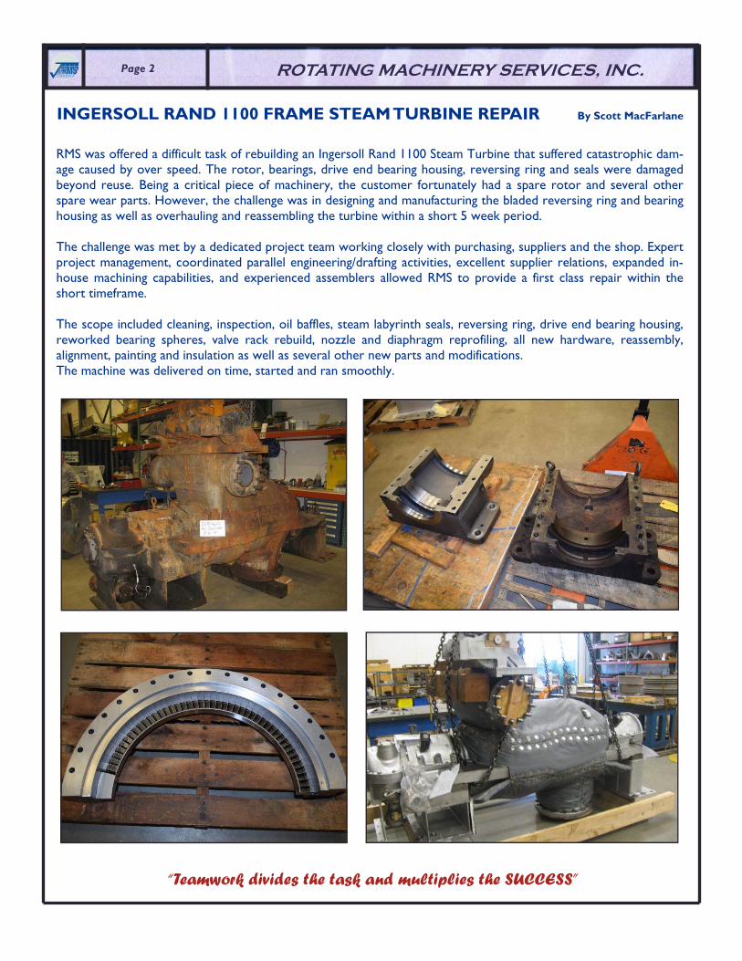
INGERSOLL RAND 1100 FRAME STEAM TURBINE REPAIR By Scott MacFarlane
RMS was offered a difficult task of rebuilding an Ingersoll Rand 1100 Steam Turbine that suffered catastrophic dam-age caused by over speed. The rotor, bearings, drive end bearing housing, reversing ring and seals were damaged beyond reuse. Being a critical piece of machinery, the customer fortunately had a spare rotor and several other spare wear parts. However, the challenge was in designing and manufacturing the bladed reversing ring and bearing housing as well as overhauling and reassembling the turbine within a short 5 week period. The challenge was met by a dedicated project team working closely with purchasing, suppliers and the shop. Expert project management, coordinated parallel engineering/drafting activities, excellent supplier relations, expanded in-house machining capabilities, and experienced assemblers allowed RMS to provide a first class repair within the short timeframe. The scope included cleaning, inspection, oil baffles, steam labyrinth seals, reversing ring, drive end bearing housing, reworked bearing spheres, valve rack rebuild, nozzle and diaphragm reprofiling, all new hardware, reassembly, alignment, painting and insulation as well as several other new parts and modifications. The machine was delivered on time, started and ran smoothly.
“Teamwork divides the task and multiplies the SUCCESS”

Volume 11, Issue 4 ������Page 3
Encountering resonant vibration of turbomachinery blades can be very damaging since small forces are amplified by vibrational energy, resulting in rapid high stress oscillations. Resonant vibrations can potentially occur with many of the different natural frequencies of a system. How can we tell if the stress levels from a particular resonance are high enough to cause fatigue failures? Often if a potential resonance is identified on a Campbell or Interference diagram it will be ignored if it is a very high order mode shape that requires a lot of energy to excite. But how can we prove that this will not be an is-sue? A harmonic response stress anal-ysis can begin to answer these ques-tions if the right information is availa-ble. Harmonic response (or frequency response) is a specific type of forced response analysis. It is a technique used to determine the steady-state stress response of a structure to loads that vary s inuso ida l l y (harmonically) with time. The loading is defined as a sine wave having ampli-tude at a specific frequency. Harmonic response provides the capability to predict the stress & deformation ex-perienced during an oscillating vibra-tion, thus enabling the verification of whether or not a structure can over-come resonance. However, it does not predict stress during transient vibration events or vibration from random acoustic noise. It can be specifically applied to the case of rotor blade vibration excited by vane wakes since they generate sinusoidally time-varying forces on the blades. In order to perform a harmonic response analysis, only a few more things are required beyond what has usually already been created for a static stress & modal analysis of the blade. A finite element model of the blade is used to find the blade natural frequencies. Then the frequency range of interest around a potential resonance point is used to pinpoint the analysis. Although the harmonic response can be generated at any frequency, it makes sense to run the calculations in a small range around the frequency of the resonance point of interest to save time. The maximum stress response is typically found at the resonant frequency. Therefore it is still important to identify resonance points with a modal analysis & Campbell diagram. The two unique things needed for harmonic response analysis are the excitation force & an estimate of the materi-al damping. The excitation force from vane wakes can be approximated as a small percentage of the aerodynamic bending load on the blade estimated earlier for the static stress analysis. Excitation forces from sources other than vane wakes may be harder to estimate. The material damping ratio (or log dec) is an estimate of the inherent damping inside the metals crystal structure. This damping ratio does not generally include the effects of frictional
HARMONIC RESPONSE STRESS ANALYSIS OF BLADES IN RESONANCE By Christopher Sykora

������ ROTATING MACHINERY SERVICES, INC. Page 4
CENTRIFUGAL COMPRESSORS By Ryan Montero
damping from features like interlocking shrouds, lacing tubes, riveted joints, etc. Most rotor blade metals (Fe & Ni alloys) have approximately the same material damping value, although some like 17-4PH are slightly less damped. These damping values are available in published sources. The resulting stress response of the blade will be inversely proportional to the amount of damping included in the analysis. More damping = less stress. The results of a harmonic response analysis have two steps. The first is to create an X-Y plot (Figure 1) of deformation output (typically at the blade tip) vs. input frequen-cy in order confirm the location of the peak response. Second, the harmonic re-sponse stresses (Figure 2) can be extracted at the peak response frequency just like in a static stress analysis. The stress values extracted can be used as the alternating stress component of a Goodman diagram to check whether or not the part will be resistant to fatigue at that particular resonance point. This type of analysis can be used during the design phase to verify that resonance at a higher order mode can be ignored. Or it can be used during a root cause failure investigation to confirm that resonance of a particular mode shape was the cause of fatigue failure. It can be used on any of the bladed turbomachinery components (plus impellers) as long as the excitation force & direction can be confidently estimated & applied to the finite element model.
HARMONIC RESPONSE STRESS ANALYSIS OF BLADES IN RESONANCE (Con’t)
SURGE IN COMPRESSORS
Centrifugal compressors are a staple and a workhorse for many modern refining, chemical, and energy related pro-cesses. In order to maintain continuous and reliable operation, it is im-perative that adequate surge margin is maintained.
When forward flow cannot be maintained, the high pressure discharge reservoir can cause flow in the compressor to reverse and surge will occur. Surge in a compressor is preceded by flow separation from the blade, or “stall”. Stall also occurs on airplane wings; when incidence becomes too great the boundary layer detaches from the wing and lift is no longer generated. In the case of an impellor as the flow decreases and the discharge pressure increases, the flow becomes detached from the airfoil and the impeller no longer imparts work on the gas. The de-tached boundary layer creates an area of recirculation in the bladed passage. The flow instabilities resulting from the stalled impeller mani-fest themselves as vibration in the rotor that can cause serious damage, in many cases failure, to compressor components. Failed Centrifugal Compressor
Impeller due to Surge Event

Page 5 ������Page 5 ������Volume 11, Issue 4
CFD Flow Visualization of Recirculation in a Centrifugal Compressor Blade Passage Due to the violent nature of surge events, it is critical to design adequate surge margin into the compressor and maintain it with adequate surge avoidance controls. An operating point, or range, must be established during compres-sor design; and if any changes are made in op-eration, they must be evaluated to ensure ade-quate surge margin. Typically, surge control algorithms are in-formed by the compressor curves supplied by the compressor OEM, which will specify a surge line for the compressor. From the surge line, a surge limit line will be created. The surge limit line will decide the minimum flow allowed during operation. A good rule of thumb for adequate surge limit line is about 5% in compressor head or 10% flow, whichever provides greater margin, from the surge line. A surge event can cause irreparable damage to compressors and leave processes that require these machines down for weeks; don’t let surge happen to you!
CENTRIFUGAL COMPRESSORS (Con’t)
RMS STAFF HOLIDAY FUN! - UGLY SWEATER CONTEST
Here at RMS not only does our staff work hard to ensure our customers receive the best service possible, but we sometimes take a break and kick up our heels! RMS held its 2nd annual Holiday Ugly Sweater contest this year over breakfast at the GreenPond Country Club. We had a great turn out with some pretty ugly sweaters!
1st Place - Blaine Christman, RMS’s Machinist 2nd Place - Kerry Frank, RMS’s Lead NDT Technician
3rd Place - Gabrielle Koltisko, RMS Administrative Assistant

ROTATING MACHINERY SERVICES, INC. ������ Page 6
EMPLOYEE HIGHLIGHT - ROBERT DEHART, ASQ CQT
RMS highlights Bob Dehart, RMS Quality Control Inspector. Bob has a great passion and love for gardening. Bob shares tips and some in-depth knowledge on this subject. Sampling Inspection as a Tool to Improve Greenhouse Crop Quality
One the most difficult skills for a grower to cultivate is correctly identifying the real ‘limiting factors’ of growth. Several variables play a role in the production of greenhouse crops. A few of these var-iables are air temperature/humidity, soil temperature, soil fertility, moisture, light intensity, water quality, air quality and soil electrical conductivity (EC). Soil EC is related to specific soil properties that affect crop yield, such as pH, salt concentrations and water-holding capacity. Thus EC is a great tool for understanding what crop yields could be and what action could be taken to get better yields. Although measurements of these variables are relatively easy, the data is only useful if the measuring instruments are used correctly and the limita-tions of the instruments are understood. Optimizing the value of the col-lected data requires selecting the best sensor(s) for a particular purpose, determining the optimal number of sensors to be deployed, and assuring that collected data are as accurate and precise as possible. When initi-ating a measurement program, there is no h i s tor i ca l process knowledge on which to base a reasonable sam-pling strategy. In these cases, consider sampling 100 percent for as long as it takes to expose the process variability pat-terns, and then, if conditions warrant, reduce sampling as you begin to better understand the process behavior. The goal is to detect special causes of process variability so that immedi-ate corrective action can be taken. Measurement sampling uses control charts to track the process’s ability to maintain a stable mean with con-sistent variability about that mean. Ideally, the mean of the data stream is very close to the desired feature’s target value. Any measurements out-side the upper or lower control limits would indicate the process mean or variability has deviated from historical norms. The ideal sampling plan will statistically minimize the probability of accept-ing bad product when the appropriate confidence interval is chosen.

Page 7 ������Page 7 ������Volume 11, Issue 4
WELCOME - NEW EMPLOYEES
JEFFREY V. ELLIS - CHIEF FINANCIAL OFFICER Jeffrey V. Ellis joins the RMS Team as the Chief Financial Officer. Jeff is a Certified Public Account-ant, with a BS in Economics from Penn State, and a MBA in Finance & Accounting from Duques-ne. He has an impressive background beginning with Peat Marwick followed by positions at Kvaerner, Genesis WWII, Siemens, Harsco, Forge Group and most recently Somerset Coal inter-national, a small equity back startup. Jeff has experience in both domestic and internation-al assignments as Manager, Controller and VP of Finance.
His skill set reflects his extensive experience including Lean Kaizen, ERP implementations (SAP, Oracle, JD Edwards, QuickBooks, Visibility, and Hyperion Reporting), Working Capital Management, Merger and Acquisitions Integra-tion, Risk Management, Change Management and Lender Relationships.
THOMAS KEATING, P.E. - SR. DESIGN ENGINEER Tom joins the RMS team as Senior Engineer. Tom has worked as a design engineer, service engi-neer and engineering manager for companies such as Air Products, 3M and Alfa Laval, designing and working on centrifuges, centrifugal pumps, compressors and pressure vessels. He earned an M.S. in Mechanical Engineering from Drexel University and a B.S. in Mechanical Engineering from Lehigh University, and is a licensed professional engineer in Pennsylvania. Looking to apply his experience and contribute to our business, Tom is excited to join the RMS team. Tom resides in Kulpsville
along with his wife, Aliki, and two sons, Alexander and George and their adopted neighborhood cat Meeka.
ALAN NEAS - CAD DESIGNER Alan joins the RMS Team as a CAD Designer. He worked as a design drafter for GE for the last 15 years and CONMEC for 11 years. His experience includes work with axial and centrifugal com-pressors and hot gas expander as well as steam turbines. Prior to his turbo-machinery experience, Alan was a 3D CAD drafter for Mack Trucks for 12 years. He and his wife Denise have been mar-ried for 44 years with 3 children and 5 grand-children.
FCC POWER RECOVERY TRAIN ROUNDTABLE AT RMS
The RMS FCC Power Recovery Train Roundtable was held on October 27 & 28, 2015. We had a great attendee turnout. RMS received very positive feedback from the attendees… “...valuable technical information presented”, “...presenters very knowledgeable”, “...learned some valuable information in the group discussions” were just some of the comments. Due to the high demand and positive feedback we received once again, we will continue to host the con-ference in 2016 in October or November. Details will follow in the next issue of the RMS Finish Line. Registration packets will be distributed in March/April 2016. If interested in attending and to ensure you receive a registration packet, you can contact via email Kathy Ehasz at [email protected] or Don Shafer at [email protected] to be put on the FCC PRT Roundtable list.
Roundtable topics of discussion include, process and PRT overview, expander reliability, catalyst deposition, erosion, corrosion, on-line techniques to improve expander reliability, axial compressor theory of operation and typical con-struction, expander and axial aerodynamics, flow path design basics, performance, upgrades and much more.
No matter your experience, you will leave with a better knowledge of Power Recovery Trains. Hope you plan to join us!

Page 8 ������Page 8 ������ ROTATING MACHINERY SERVICES, INC.
WINTER DRIVING SAFETY TIPS By Tom Edwards
AAA recommends the following winter driving tips:
Avoid driving while you’re fatigued. Getting the proper amount of rest before taking on winter weather tasks reduces driving risks.
Never warm up a vehicle in an enclosed area, such as a garage. Make certain your tires are properly inflated. Never mix radial tires with other tire types. Keep your gas tank at least half full to avoid gas line freeze-up. If possible, avoid using your parking brake in cold, rainy and snowy weather. Do not use cruise control when driving on any slippery surface (wet, ice, sand). Always look and steer where you want to go. Use your seat belt every time you get into your vehicle.
Tips for long-distance winter trips: Watch weather reports prior to a long-distance drive or before driving in isolated areas. Delay trips when espe-
cially bad weather is expected. If you must leave, let others know your route, destination and estimated time of arrival.
Always make sure your vehicle is in peak operating condition by having it inspected. Keep at least half a tank of gasoline in your vehicle at all times. Pack a cellular telephone with your local AAA’s telephone number, plus blankets, gloves, hats, food, water and
any needed medication in your vehicle. If you become snow-bound, stay with your vehicle. It provides temporary shelter and makes it easier for rescu-
ers to locate you. Don’t try to walk in a severe storm. It’s easy to lose sight of your vehicle in blowing snow and become lost.
Don’t over exert yourself if you try to push or dig your vehicle out of the snow. Tie a brightly colored cloth to the antenna or place a cloth at the top of a rolled up window to signal distress. At
night, keep the dome light on if possible. It only uses a small amount of electricity and will make it easier for res-cuers to find you.
Make sure the exhaust pipe isn’t clogged with snow, ice or mud. A blocked exhaust could cause deadly carbon monoxide gas to leak into the passenger compartment with the engine running.
Use whatever is available to insulate your body from the cold. This could include floor mats, newspapers or pa-per maps.

������Page 9 Volume 11, Issue 4

������ Page 10 ROTATING MACHINERY SERVICES, INC.

������Page 11 Volume 11, Issue 4
ANALYSIS REVERSE
BAFFLES SCOPE
DIAGRAM SEALS
ENGINEERING SOLUTIONS
FREQUENCY STRESS
HARMONIC TURBOMACHINERY
LABYRINTH VIBRATION
MODAL
POWER
RATIO
REPAIR
RESONANCE
Fill in the grid with digits in such a manner that every row, every column and every 3x3 box
accommodates the digits 1-9, without repeating any. (answer on back cover)

2760 Baglyos Circle Bethlehem, PA 18020
Phone: 484-821-0702 / Fax: 484-821-0710 www.RotatingMachinery.com
ROTATING MACHINERY SERVICES, INC.
PRODUCT LINES
AXIAL COMPRESSORS •
CENTRIFUGAL COMPRESSORS •
EXPANDERS • GAS TURBINES •
POWER TURBINES • STEAM TURBINES
������
TURBOMACHINERY SPECIALIST
An operator of a gas turbine driven pipeline compressor noted excessive oil usage at the impeller end journal bear-ing. Rotor vibration was typical and bearing temperature was typical at approximately 180F. Journal bearing failure was discovered after disassembly. The damage to the bearing indicated Babbitt fatigue, separation and melting. Loss of adhesion and molten Babbitt can be seen in the photographs. Most of the damage was located at the outboard (i.e., impeller) end of the bearing where the oil is contained by a floating seal. A failure investigation was not performed but excessive oil flow through a worn floating seal was suspected to be the root cause. The compressor typically operates in cyclic service subjecting the bearing to numerous starts and stops, as well as startup and shutdown vibration transients. The bearing had operated for approximately seven years. Fortunately, there was no damage to the shaft and the unit was restarted after installing a spare bearing.
PIPELINE COMPRESSOR JOURNAL BEARING FAILURE By Anthony Rubino, P.E.
Answer to Sudoku Puzzle on page 11