Embed Size (px)
Citation preview

PDUElectrical · Drives · Servo-motors
300 w w w . s c h u n k . c o m
Sizes70 .. 110
Weight1.6 kg .. 5.5 kg
Nominal torque7 Nm .. 142 Nm
Repeat accuracy0.002° .. 0.004°
Application example
Sturdy Spindle Axis driven by PDU motor Linear Axis with PLS 70 ball-and-screw spindle drive
Servo-motor with PDU 70 precision gears
19_PDU_GB.qxd:Layout 1 29.04.2008 10:51 Uhr Seite 300

PDUElectrical · Drives · Servo-motors
301w w w . s c h u n k . c o m
High torques through Harmonic Drive® gearfor optimum reserves in acceleration and braking
High-resolution encoderfor high precision
Fully integrated control and power electronicsfor the creation of a decentralized control system, no separatemotor controller required in the control cabinet
Versatile actuation optionsfor simple integration in existing servo-controlled concepts via Profibus DP, CAN bus or RS-232
Standard connecting elements and uniform control conceptfor extensive combinatorics with other PowerCube modules (see explanation of the PowerCube system)
Single-cable technology for data transmission and power supply (plug & play)for low assembly and start-up costs
Servo-positioning motor with precision gears
Servo-motor
Area of applicationServo-drive for linear, rotary or CNC axes;axis motor for applications in the field of measuring and testing
Your advantages and benefits
Information about the seriesWorking principlewith Harmonic Drive® gear driven by a brushless DC servo-motor
Housing materialAluminum alloy, hard-anodized
ActuationServo-electric, with brushless servo-motor and incremental encoder for position andspeed control
Warranty24 months
Scope of delivery“PowerCube Standard Software“ CD-ROM, containing assembly and operating manual with manufacturer’s declaration, quick-step software, demo and diagnosticprogram and various driver files (see explanation of PowerCube system).
Optional extras· Magnetic brake· Input for external encoder signal· Outdoor modification
Other information· Unit suitable for use in clean room environment· 4 digital EIA 24 VDC· Differential encoder signal output (RS-422)
19_PDU_GB.qxd:Layout 1 29.04.2008 10:51 Uhr Seite 301
PDUElectrical · Drives · Servo-motors
302 w w w . s c h u n k . c o m
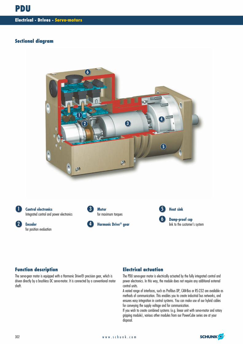
Control electronicsIntegrated control and power electronics
Encoderfor position evaluation
Motorfor maximum torques
Harmonic Drive® gear
Heat sink
Damp-proof caplink to the customer’s system
The servo-gear motor is equipped with a Harmonic Drive® precision gear, which isdriven directly by a brushless DC servo-motor. It is connected by a conventional motorshaft.
Function descriptionThe PDU servo-gear motor is electrically actuated by the fully integrated control andpower electronics. In this way, the module does not require any additional externalcontrol units.A varied range of interfaces, such as Profibus DP, CAN-Bus or RS-232 are available asmethods of communication. This enables you to create industrial bus networks, andensures easy integration in control systems. You can make use of our hybrid cablesfor conveying the supply voltage and for communication.If you wish to create combined systems (e.g. linear unit with servo-motor and rotarygripping module), various other modules from our PowerCube series are at your disposal.
Electrical actuation
Sectional diagram
19_PDU_GB.qxd:Layout 1 29.04.2008 10:51 Uhr Seite 302
PDUElectrical · Drives · Servo-motors
303w w w . s c h u n k . c o m
Repeat accuracyRepeat accuracy is defined as the spread of the limit position after 100 consecutivemotion cycles.
Position of motor shaftThe position of the motor shaft is always shown in the drawing in the zero position (0°). From here, the motor shaft can be rotated clockwise and anti-clockwise until the memory for the position value in the control electronics overflows.
Swiveling timeSwiveling times are purely rotation times. Relay switching times or SPC reactiontimes are not included in the above times and must be taken into consideration whendetermining cycle times. Load-dependent rest periods may have to be included in thecycle time.
General information on the series
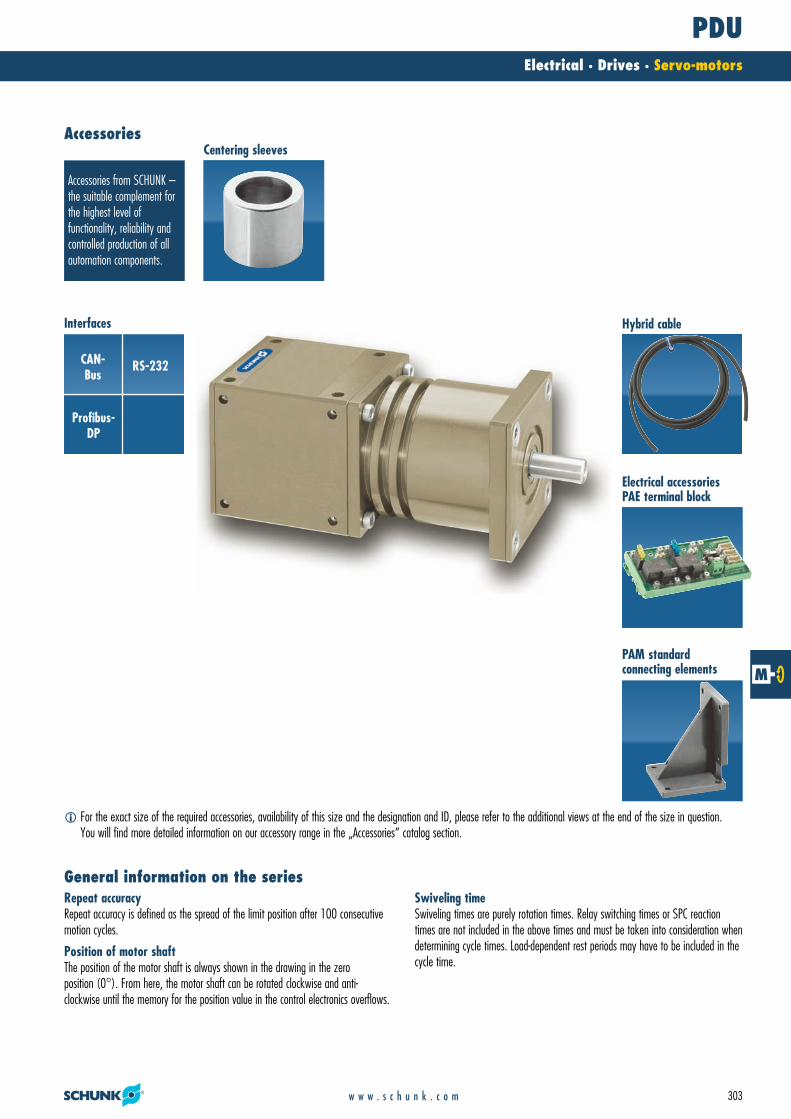
Accessories from SCHUNK –the suitable complement forthe highest level of functionality, reliability andcontrolled production of allautomation components.
CAN-Bus
RS-232
Profibus-DP
Centering sleeves
Interfaces
Electrical accessoriesPAE terminal block
PAM standard connecting elements
Accessories
Hybrid cable
� For the exact size of the required accessories, availability of this size and the designation and ID, please refer to the additional views at the end of the size in question. You will find more detailed information on our accessory range in the „Accessories“ catalog section.
19_PDU_GB.qxd:Layout 1 29.04.2008 10:51 Uhr Seite 303

PDU 70Electrical · Drives · Servo-motors
304 w w w . s c h u n k . c o m
� The peak torques act as a temporary drive reserve on acceleration and braking.* Higher accuracy on request
Technical data
Forces and moments
� Moments and forces may occur simultaneously.
Torque characteristic
0
20
40
60
0 20 40 60 80 100 120 140n [rpm]
M [N
m]
Mmax PDU 70-161 Mo PDU 70-161Mmax PDU 70-101 Mo PDU 70-101Mmax PDU 70-51 Mo PDU 70-51
Torque
Rotation speed
My max. 6.0 NmFz max. 0.0 NFx max. 50.0 N
Description PDU 70-161 PDU 70-101 PDU 70-51ID 0306703 0306713 0306723
Version with brake PDU 70-161-B PDU 70-101-B PDU 70-51-BID 0306708 0306718 0306728
Mechanical operating dataNominal torque [Nm] 23.0 15.0 7.6Peak torque [Nm] 46.0 30.0 15.0Rotating angle (>) [°] 360.0 360.0 360.0IP class 64 64 64Weight [kg] 1.6 1.6 1.6Min. ambient temperature [°C] 5.0 5.0 5.0Max. ambient temperature [°C] 55.0 55.0 55.0Repeat accuracy* [°] 0.02 0.03 0.04Max. angular velocity [°/s] 150.0 240.0 470.0Max. acceleration [°/s2] 600.0 960.0 1880.0Gear ratio 161:1 101:1 51:1Electrical operating dataNominal voltage [VDC] 24.0 24.0 24.0Nominal power current [A] 4.0 4.0 4.0Max. current [A] 8.0 8.0 8.0Resolution [arcsec] 4.0 6.0 13.0Control electronicsIntegrated control electronics Yes Yes YesVoltage supply [VDC] 24.0 24.0 24.0Nominal power current [A] 0.5 0.5 0.5Sensor system Encoder Encoder EncoderInterface RS-232; Profibus-DP; CAN-Bus RS-232; Profibus-DP; CAN-Bus RS-232; Profibus-DP; CAN-Bus
19_PDU_GB.qxd:Layout 1 29.04.2008 10:51 Uhr Seite 304

PDU 70Electrical · Drives · Servo-motors
305w w w . s c h u n k . c o m
� Voltage supply provided by customer� Control (SPC, etc.) provided by customer� PAE 130 TB terminal block for connecting the power supply, the communication and the
hybrid cable Hybrid cable for connecting the PowerCube modules
Main views
The drawing shows the servo-motor with damp-proof cap in the basic version, it doesnot include the options described below.
� Connection of rotary actuator� Attachment connection�� M16x1.5 for cable gland
ActuationDescription ID LengthPowerCube Hybrid cable, coiled 0307753 0.3 mPowerCube Hybrid cable, coiled 0307754 0.46 mPowerCube Hybrid cable, straight (per meter) 9941120Terminal block PAE 130 TB 0307725
You can find further cables in the „Accessories“ catalog section.
Electrical accessories
19_PDU_GB.qxd:Layout 1 29.04.2008 10:51 Uhr Seite 305

PDU 70Electrical · Drives · Servo-motors
306 w w w . s c h u n k . c o m
Special lengths on requestSpecial lengths on request
Right-angle connecting elementRight-angle standard element for connecting size 70 PowerCube modules with completerepeat accuracyDescription ID DimensionsPAM 120 0307820 90°/70.5x98
Conical connecting elementConical standard element for connecting size 70 and 90 PowerCube modules with complete repeat accuracyDescription ID DimensionsPAM 110 0307810 90x90/45/70x70 mmPAM 111 0307811 90x90/90/70x70 mm
Straight connecting elementStraight standard element for connecting size 70 PowerCube modules with complete repeat accuracyDescription ID DimensionsPAM 100 0307800 70x70/35/70x70 mmPAM 101 0307801 70x70/70/70x70 mm
Mechanical accessories
You can find more detailed information and individual parts of the above-mentioned accessories in the „Accessories“ catalog section.
19_PDU_GB.qxd:Layout 1 29.04.2008 10:52 Uhr Seite 306

PDU 70Electrical · Drives · Servo-motors
307w w w . s c h u n k . c o m
19_PDU_GB.qxd:Layout 1 29.04.2008 10:52 Uhr Seite 307

PDU 90Electrical · Drives · Servo-motors
308 w w w . s c h u n k . c o m
� The peak torques act as a temporary drive reserve on acceleration and braking.* Higher accuracy on request
Technical data
Forces and moments
� Moments and forces may occur simultaneously.
Torque characteristic
0
60
120
180
0 30 60 90 120 150n [rpm]
M [N
m]
Mmax PDU 90-161 Mo PDU 90-161Mmax PDU 90-101 Mo PDU 90-101Mmax PDU 90-51 Mo PDU 90-51
Torque
Rotation speed
My max. 9.0 NmFz max. 0.0 NFx max. 100.0 N
Description PDU 90-161 PDU 90-101 PDU 90-51ID 0306733 0306743 0306753
Version with brake PDU 90-161-B PDU 90-101-B PDU 90-51-BID 0306738 0306748 0306758
Mechanical operating dataNominal torque [Nm] 72.0 45.0 22.0Peak torque [Nm] 145.0 90.0 45.0Rotating angle (>) [°] 360.0 360.0 360.0IP class 64 64 64Weight [kg] 3.1 3.1 3.1Min. ambient temperature [°C] 5.0 5.0 5.0Max. ambient temperature [°C] 55.0 55.0 55.0Repeat accuracy* [°] 0.02 0.03 0.04Max. angular velocity [°/s] 150.0 240.0 470.0Max. acceleration [°/s2] 600.0 960.0 1880.0Gear ratio 161:1 101:1 51:1Electrical operating dataNominal voltage [VDC] 24.0 24.0 24.0Nominal power current [A] 4.0 4.0 4.0Max. current [A] 12.0 12.0 12.0Resolution [arcsec] 4.0 6.0 13.0Control electronicsIntegrated control electronics Yes Yes YesVoltage supply [VDC] 24.0 24.0 24.0Nominal power current [A] 0.5 0.5 0.5Sensor system Encoder Encoder EncoderInterface RS-232; Profibus-DP; CAN-Bus RS-232; Profibus-DP; CAN-Bus RS-232; Profibus-DP; CAN-Bus
19_PDU_GB.qxd:Layout 1 29.04.2008 10:52 Uhr Seite 308

PDU 90Electrical · Drives · Servo-motors
309w w w . s c h u n k . c o m
� Voltage supply provided by customer� Control (SPC, etc.) provided by customer� PAE 130 TB terminal block for connecting the power supply, the communication and the
hybrid cable Hybrid cable for connecting the PowerCube modules
Main views
The drawing shows the servo-motor with damp-proof cap in the basic version, it doesnot include the options described below.
� Connection of rotary actuator� Attachment connection�� M16x1.5 for cable gland
ActuationDescription ID LengthPowerCube Hybrid cable, coiled 0307753 0.3 mPowerCube Hybrid cable, coiled 0307754 0.46 mPowerCube Hybrid cable, straight (per meter) 9941120Terminal block PAE 130 TB 0307725
You can find further cables in the „Accessories“ catalog section.
Electrical accessories
19_PDU_GB.qxd:Layout 1 29.04.2008 10:52 Uhr Seite 309

PDU 90Electrical · Drives · Servo-motors
310 w w w . s c h u n k . c o m
Special lengths on request
Special lengths on request
Right-angle connecting elementRight-angle standard element for connecting size 90 PowerCube modules with completerepeat accuracyDescription ID DimensionsPAM 121 0307821 90°/90.5x122
Conical connecting elementConical standard element for connecting size 70, 90 and 110 PowerCube modules withcomplete repeat accuracyDescription ID DimensionsPAM 110 0307810 90x90/45/70x70 mmPAM 111 0307811 90x90/90/70x70 mmPAM 112 0307812 110x110/55/90x90 mmPAM 113 0307813 110x110/110/90x90 mm
Straight connecting elementStraight standard element for connecting size 90 PowerCube modules with complete repeat accuracyDescription ID DimensionsPAM 102 0307802 90x90/45/90x90 mmPAM 103 0307803 90x90/90/90x90 mm
Mechanical accessories
You can find more detailed information and individual parts of the above-mentioned accessories in the „Accessories“ catalog section.
19_PDU_GB.qxd:Layout 1 29.04.2008 10:52 Uhr Seite 310

PDU 90Electrical · Drives · Servo-motors
311w w w . s c h u n k . c o m
19_PDU_GB.qxd:Layout 1 29.04.2008 10:52 Uhr Seite 311
PDU 110Electrical · Drives · Servo-motors
312 w w w . s c h u n k . c o m
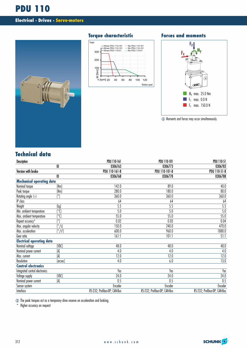
� The peak torques act as a temporary drive reserve on acceleration and braking.* Higher accuracy on request
Technical data
Forces and moments
� Moments and forces may occur simultaneously.
Torque characteristic
0
100
200
300
0 20 40 60 80 100 120n [rpm]
M [N
m]
Mmax PDU 110-161 Mo PDU 110-161Mmax PDU 110-101 Mo PDU 110-101Mmax PDU 110-51 Mo PDU 110-51
Torque
Rotation speed
My max. 25.0 NmFz max. 0.0 NFx max. 150.0 N
Description PDU 110-161 PDU 110-101 PDU 110-51ID 0306763 0306773 0306783
Version with brake PDU 110-161-B PDU 110-101-B PDU 110-51-BID 0306768 0306778 0306788
Mechanical operating dataNominal torque [Nm] 142.0 89.0 40.0Peak torque [Nm] 280.0 180.0 80.0Rotating angle (>) [°] 360.0 360.0 360.0IP class 64 64 64Weight [kg] 5.5 5.5 5.5Min. ambient temperature [°C] 5.0 5.0 5.0Max. ambient temperature [°C] 55.0 55.0 55.0Repeat accuracy* [°] 0.02 0.03 0.04Max. angular velocity [°/s] 150.0 240.0 470.0Max. acceleration [°/s2] 600.0 960.0 1880.0Gear ratio 161:1 101:1 51:1Electrical operating dataNominal voltage [VDC] 48.0 48.0 48.0Nominal power current [A] 4.0 4.0 4.0Max. current [A] 12.0 12.0 12.0Resolution [arcsec] 4.0 6.0 13.0Control electronicsIntegrated control electronics Yes Yes YesVoltage supply [VDC] 24.0 24.0 24.0Nominal power current [A] 0.5 0.5 0.5Sensor system Encoder Encoder EncoderInterface RS-232; Profibus-DP; CAN-Bus RS-232; Profibus-DP; CAN-Bus RS-232; Profibus-DP; CAN-Bus
19_PDU_GB.qxd:Layout 1 29.04.2008 10:52 Uhr Seite 312

PDU 110Electrical · Drives · Servo-motors
313w w w . s c h u n k . c o m
� Voltage supply provided by customer� Control (SPC, etc.) provided by customer� PAE 130 TB terminal block for connecting the power supply, the communication and the
hybrid cable Hybrid cable for connecting the PowerCube modules
Main views
The drawing shows the servo-motor with damp-proof cap in the basic version, it doesnot include the options described below.
� Connection of rotary actuator� Attachment connection�� M16x1.5 for cable gland
ActuationDescription ID LengthPowerCube Hybrid cable, coiled 0307753 0.3 mPowerCube Hybrid cable, coiled 0307754 0.46 mPowerCube Hybrid cable, straight (per meter) 9941120Terminal block PAE 130 TB 0307725
You can find further cables in the „Accessories“ catalog section.
Electrical accessories
19_PDU_GB.qxd:Layout 1 29.04.2008 10:52 Uhr Seite 313

PDU 110Electrical · Drives · Servo-motors
314 w w w . s c h u n k . c o m
Special lengths on requestSpecial lengths on request
Right-angle connecting elementRight-angle standard element for connecting size 110 PowerCube modules with completerepeat accuracyDescription ID DimensionsPAM 122 0307822 90°/110.5x146
Conical connecting elementConical standard element for connecting size 90 and 110 PowerCube modules with complete repeat accuracyDescription ID DimensionsPAM 112 0307812 110x110/55/90x90 mmPAM 113 0307813 110x110/110/90x90 mm
Straight connecting elementStraight standard element for connecting size 110 PowerCube modules with completerepeat accuracyDescription ID DimensionsPAM 104 0307804 110x110/55/110x110 mmPAM 105 0307805 110x110/110/110x110 mm
Mechanical accessories
You can find more detailed information and individual parts of the above-mentioned accessories in the „Accessories“ catalog section.
19_PDU_GB.qxd:Layout 1 29.04.2008 10:52 Uhr Seite 314

PDU 110Electrical · Drives · Servo-motors
315w w w . s c h u n k . c o m
19_PDU_GB.qxd:Layout 1 29.04.2008 10:52 Uhr Seite 315
Text6D · Text7D · Text9D
316 w w w . s c h u n k . c o m
Accessories
20_Einl_Zubehoer_GB.qxd:Layout 1 29.04.2008 11:00 Uhr Seite 316

Accessories
317w w w . s c h u n k . c o m
ACCE
SSO
RIES
Series Size Page
Accessories
Inductive Proximity Switches IN 318
IN 3 320
IN 5 322
IN 8 324
IN 40 326
IN 60 328
IN 65 330
IN 80 332
IN B-80/80SL 334
IN 120 336
Reed Switches RMS 338
RMS 22 340
RMS 80 342
Magnetic Switches MMS 344
MMS 22 346
MMS 22-SA 348
MMS 30 350
MMSK 65 352
Optical Switch ONS 354
ONS 01 356
Switch Accessories SST 358
SST 360
NHG 362
Sensor Distributor V 366
V 2 368
V 4 372
V 8 376
Cable and Connector fluidic 380
KV 382
WK 384
KST-M8/KBU-M8 386
KST-M12/MBU-M12 388
Measuring Systems APS-M1 390
APS-M1 392
FPS/FPS-S/FPS-A/FPS Software 394
FMS/FMS-A/FMS-ZBA/-ZBP 402
Transmission Systems RSS 412
RSS/RSS-T2/RSS-R1 414
Fluidic Monitoring System PA3 418
PA3 420
Series Size Page
Accessories
Mounting Elements 422
Centering Elements ZHU 422
PAM 426
Valves and Screw Connections 434
SDV-P 436
WV-G 438
SWV 440
DSV 442
Grease 444
Grease 444
Cable and Connector electric 446
Hybrid Cable PAE 448
Connecting Cable for MEG 450
Tools SLZ 452
Hose Release Pliers SLZ 454
20_Einl_Zubehoer_GB.qxd:Layout 1 29.04.2008 11:00 Uhr Seite 317

INAccessories · Sensor System · Switches · Inductive Proximity Switches
318 w w w . s c h u n k . c o m
With their oscillator coil, inductive proximity switches produce a high-frequency, alternating magnetic field. This field occurs on the active surface of the sensor.If a metal object enters the field, it draws energy from the magnetic field, therebyreducing the oscillation amplitude. This change is detected, and the sensor switches.
Function descriptionMounting through bracketfor simple, fast assembly
Version with LED displayfor checking the switching state directly at the sensor
Version with connectorfor easy, rapid replacement of the extension cable
Ultra-flexible PUR cablefor a long life and resistance to many chemicals
Proximity switch can be installed flushfor minimal interfering contours in the application
Your advantages and benefits
Inductive Proximity Switches
Inductive proximity switches are used to monitor the current position of automation components. They are available from SCHUNK in the versions IN (sensor with 30 cm molded cable andcable connector) or INK (sensor with 2 m long feeder cable and litz wires for wiring).
21_Zub_Sensorik.qxd:Layout 1 29.04.2008 11:07 Uhr Seite 318

INAccessories · Sensor System · Switches · Inductive Proximity Switches
319w w w . s c h u n k . c o m
Plug-in IN Sensors
PSK Swivel Head
PGN 2-Finger Parallel Gripper withABR finger blanks
PZN 3-Finger Centric Gripper withworkpiece-specific gripper fingers
Protection class according to DIN 40050IP 67 in connected condition for use in clean or dusty environments or in the eventof contact with water. Contact with other media (cooling lubricants, acidic or causticsubstances, etc.) frequently does not impair the function, but this cannot be guaranteed by SCHUNK.
Voltage10 – 30 V DC, residual ripple < 15 %
Switching methodPNP switching
Warranty24 months
General informationSCHUNK gripping, rotary and linear modules and robot accessory components mustalways be ordered from SCHUNK with the matching sensors, as these are ideallyadapted to work together.
If major characteristics such as switching distance, switching function, hysteresis andvoltage are largely the same, then proximity switches from other manufacturers maybe used instead of inductive proximity switches (IN, INK) from SCHUNK.
However, if proximity switches from other manufacturers are used, SCHUNK cannotguarantee either their function or their functional reliability.
Notes
Application example
For monitoring of gripping and rotary modules, linearmodules and robot accessories. Inductive SCHUNK sensors detect metals without contact and are resistantto vibration, dust and humidity.
Area of application
21_Zub_Sensorik.qxd:Layout 1 29.04.2008 11:07 Uhr Seite 319

IN 3Accessories · Sensor System · Switches · Inductive Proximity Switches
320 w w w . s c h u n k . c o m
� The cable between the sensor and the club must not be disconnected in any case.
Technical data
Circuit diagram of closer
1
3
4
Description IN 3-S-M8-PNPID 0301466
Switching function CloserSwitching distance [mm] 0.6Hysteresis of nominal switching distance < 5%Switching method PNPCable length [cm] 30.0Cable connector/cable end M8Type of voltage DCNominal voltage [V] 24.0Min. voltage [V] 10.0Max. voltage [V] 30.0Voltage drop [V] 1.5Max. power on contact [A] 0.1Min. ambient temperature [°C] -25.0Max. ambient temperature [°C] 75.0Max. switching frequency [Hz] 1000.0IP class (sensor) 67IP class (connector, plugged in) 67LED display on sensor NoCable diameter [mm] 2.5Min. bending radius (dynamic) [mm] 25.0Min. bending radius (static) [mm] 12.5No. of wires 3Wire cross section [mm2] 0.14
21_Zub_Sensorik.qxd:Layout 1 29.04.2008 11:07 Uhr Seite 320

IN 3Accessories · Sensor System · Switches · Inductive Proximity Switches
321w w w . s c h u n k . c o m
�� LED�� Active sensor surface
IN 3 sensor M8 connector
21_Zub_Sensorik.qxd:Layout 1 29.04.2008 11:07 Uhr Seite 321

IN 5Accessories · Sensor System · Switches · Inductive Proximity Switches
322 w w w . s c h u n k . c o m
Technical data
Circuit diagram of closer
1
3
4
Description IN 5-S-M8 IN 5-S-M12 INK 5-SID 0301469 0301569 0301501
Switching function Closer Closer CloserSwitching distance [mm] 1.0 1.0 1.0Hysteresis of nominal switching distance < 15% < 15% < 15%Switching method PNP PNP PNPCable length [cm] 30.0 30.0 200.0Cable connector/cable end M8 M12 Open wireType of voltage DC DC DCNominal voltage [V] 24.0 24.0 24.0Min. voltage [V] 10.0 10.0 10.0Max. voltage [V] 30.0 30.0 30.0Voltage drop [V] 1.5 1.5 1.5Max. power on contact [A] 0.2 0.2 0.2Min. ambient temperature [°C] -25.0 -25.0 -25.0Max. ambient temperature [°C] 70.0 70.0 70.0Max. switching frequency [Hz] 1000.0 1000.0 1000.0IP class (sensor) 67 67 67IP class (connector, plugged in) 67 67 67LED display on sensor No No NoCable diameter [mm] 3.5 3.5 3.5Min. bending radius (dynamic) [mm] 35.0 35.0 35.0Min. bending radius (static) [mm] 17.5 17.5 17.5No. of wires 3 3 3Wire cross section [mm2] 0.14 0.14 0.14
21_Zub_Sensorik.qxd:Layout 1 29.04.2008 11:07 Uhr Seite 322

IN 5Accessories · Sensor System · Switches · Inductive Proximity Switches
323w w w . s c h u n k . c o m
�� Active sensor surface
IN 5/S sensor M8 connector
M12 connector
21_Zub_Sensorik.qxd:Layout 1 29.04.2008 11:07 Uhr Seite 323

IN 8Accessories · Sensor System · Switches · Inductive Proximity Switches
324 w w w . s c h u n k . c o m
Technical data
Circuit diagram of closer
1
3
4
Description IN 8-S-M8 IN 8-S-M12 INK 8-SID 0301481 0301581 9700052
Switching function Closer Closer CloserSwitching distance [mm] 0.8 0.8 0.8Hysteresis of nominal switching distance < 15% < 15% < 15%Switching method PNP PNP PNPCable length [cm] 30.0 30.0 200.0Cable connector/cable end M12 M12 Open wireType of voltage DC DC DCNominal voltage [V] 24.0 24.0 24.0Min. voltage [V] 10.0 10.0 10.0Max. voltage [V] 30.0 30.0 30.0Voltage drop [V] 1.5 1.5 1.5Max. power on contact [A] 0.2 0.2 0.2Min. ambient temperature [°C] -25.0 -25.0 -25.0Max. ambient temperature [°C] 70.0 70.0 70.0Max. switching frequency [Hz] 1000.0 1000.0 1000.0IP class (sensor) 67 67 67IP class (connector, plugged in) 67 67 67LED display on sensor No No NoCable diameter [mm] 3.5 3.5 3.5Min. bending radius (dynamic) [mm] 35.0 35.0 35.0Min. bending radius (static) [mm] 17.5 17.5 17.5No. of wires 3 3 3Wire cross section [mm2] 0.14 0.14 0.14
21_Zub_Sensorik.qxd:Layout 1 29.04.2008 11:07 Uhr Seite 324

IN 8Accessories · Sensor System · Switches · Inductive Proximity Switches
325w w w . s c h u n k . c o m
�� Active sensor surface
IN 8/S sensor M8 connector
M12 connector
21_Zub_Sensorik.qxd:Layout 1 29.04.2008 11:07 Uhr Seite 325

IN 40Accessories · Sensor System · Switches · Inductive Proximity Switches
326 w w w . s c h u n k . c o m
Technical data
Circuit diagram of openerCircuit diagram of closer
1
3
4
1
3
4
Description IN 40-S-M8 IN 40-S-M12 INK 40-S IN 40-O-M8 IN 40-O-M12 INK 40-O IN 40-S-M5-PNP IN 40-S-M5-NPNID 0301474 0301574 0301555 0301484 0301584 0301556 0301491 0301492
Switching function Closer Closer Closer Opener Opener Opener Closer CloserSwitching distance [mm] 0.8 0.8 0.8 0.8 0.8 0.8 0.8 0.8Hysteresis of nominal switching distance < 15% < 15% < 15% < 15% < 15% < 15% < 15% < 15%Switching method PNP PNP PNP PNP PNP PNP PNP NPNCable length [cm] 30.0 30.0 200.0 30.0 30.0 200.0 30.0 30.0Cable connector/cable end M8 M12 Open wire M8 M12 Open wire M8 M8Type of voltage DC DC DC DC DC DC DC DCNominal voltage [V] 24.0 24.0 24.0 24.0 24.0 24.0 24.0 24.0Min. voltage [V] 10.0 10.0 10.0 10.0 10.0 10.0 10.0 10.0Max. voltage [V] 30.0 30.0 30.0 30.0 30.0 30.0 30.0 30.0Voltage drop [V] 1.5 1.5 1.5 1.5 1.5 1.5 1.5 1.5Max. power on contact [A] 0.2 0.2 0.2 0.2 0.2 0.2 0.2 0.2Min. ambient temperature [°C] -25.0 -25.0 -25.0 -25.0 -25.0 -25.0 -25.0 -25.0Max. ambient temperature [°C] 70.0 70.0 70.0 70.0 70.0 70.0 70.0 70.0Max. switching frequency [Hz] 1000.0 1000.0 1000.0 1000.0 1000.0 1000.0 1000.0 1000.0IP class (sensor) 67 67 67 67 67 67 67 67IP class (connector, plugged in) 67 67 67 67 67 67 67 67LED display on sensor Yes Yes Yes Yes Yes Yes Yes YesCable diameter [mm] 3.5 3.5 3.5 3.5 3.5 3.5 3.5 3.5Min. bending radius (dynamic) [mm] 35.0 35.0 35.0 35.0 35.0 35.0 35.0 35.0Min. bending radius (static) [mm] 17.5 17.5 17.5 17.5 17.5 17.5 17.5 17.5No. of wires 3 3 3 3 3 3 3 3Wire cross section [mm2] 0.14 0.14 0.14 0.14 0.14 0.14 0.14 0.14
21_Zub_Sensorik.qxd:Layout 1 29.04.2008 11:07 Uhr Seite 326

IN 40Accessories · Sensor System · Switches · Inductive Proximity Switches
327w w w . s c h u n k . c o m
�� Active sensor surface
IN 40 sensor M8 connector
M12 connector
21_Zub_Sensorik.qxd:Layout 1 29.04.2008 11:07 Uhr Seite 327

IN 60Accessories · Sensor System · Switches · Inductive Proximity Switches
328 w w w . s c h u n k . c o m
Technical data
Circuit diagram of closer
1
3
4
Description IN 60-S-M8 IN 60-S-M12 INK 60-SID 0301485 0301585 0301553
Switching function Closer Closer CloserSwitching distance [mm] 1.5 1.5 1.5Hysteresis of nominal switching distance < 15% < 15% < 15%Switching method PNP PNP PNPCable length [cm] 30.0 30.0 200.0Cable connector/cable end M8 M12 Open wireType of voltage DC DC DCNominal voltage [V] 24.0 24.0 24.0Min. voltage [V] 10.0 10.0 10.0Max. voltage [V] 30.0 30.0 30.0Voltage drop [V] 1.5 1.5 1.5Max. power on contact [A] 0.2 0.2 0.2Min. ambient temperature [°C] -25.0 -25.0 -25.0Max. ambient temperature [°C] 70.0 70.0 70.0Max. switching frequency [Hz] 1000.0 1000.0 1000.0IP class (sensor) 67 67 67IP class (connector, plugged in) 67 67 67LED display on sensor No No NoCable diameter [mm] 3.5 3.5 3.5Min. bending radius (dynamic) [mm] 35.0 35.0 35.0Min. bending radius (static) [mm] 17.5 17.5 17.5No. of wires 3 3 3Wire cross section [mm2] 0.14 0.14 0.14
21_Zub_Sensorik.qxd:Layout 1 29.04.2008 11:07 Uhr Seite 328

IN 60Accessories · Sensor System · Switches · Inductive Proximity Switches
329w w w . s c h u n k . c o m
�� Active sensor surface
IN 60/S sensor M8 connector
M12 connector
21_Zub_Sensorik.qxd:Layout 1 29.04.2008 11:07 Uhr Seite 329
IN 65Accessories · Sensor System · Switches · Inductive Proximity Switches
330 w w w . s c h u n k . c o m
Technical data
Circuit diagram of closer
1
3
4
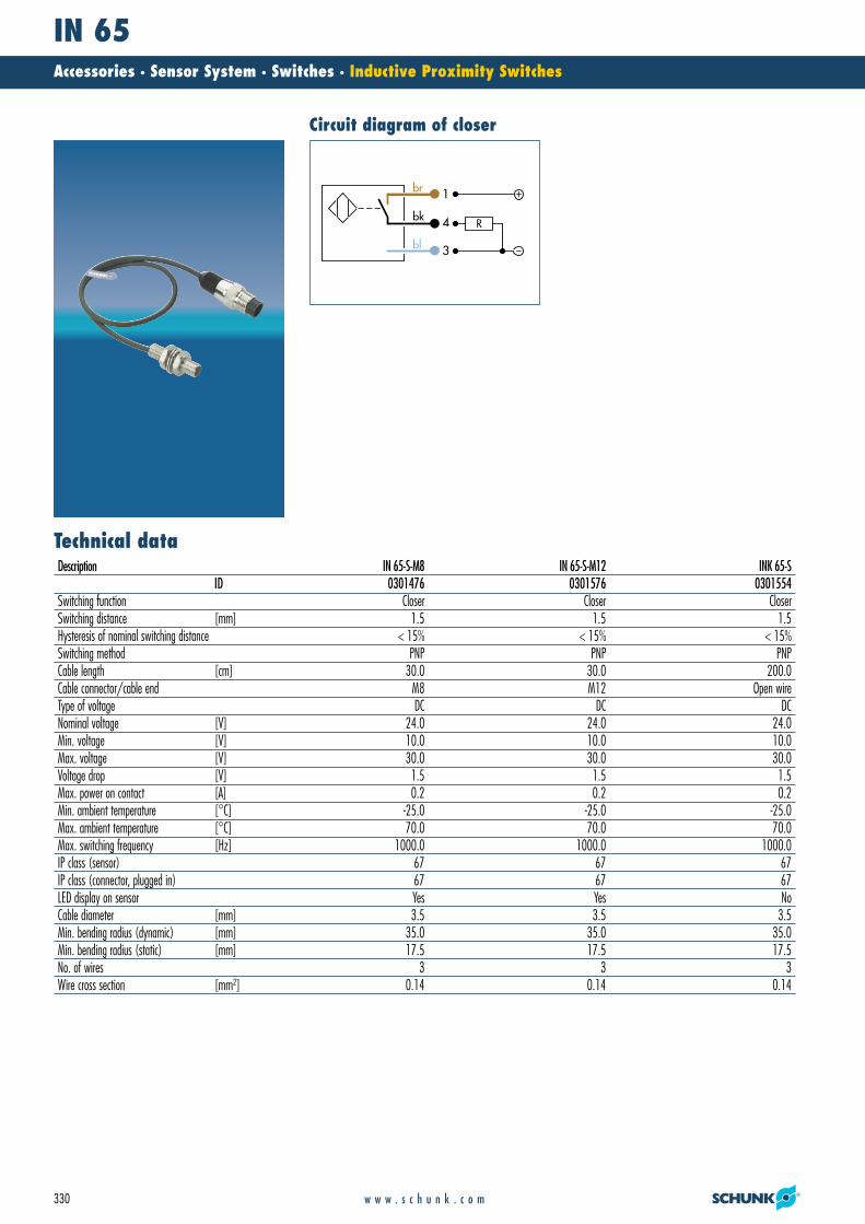
Description IN 65-S-M8 IN 65-S-M12 INK 65-SID 0301476 0301576 0301554
Switching function Closer Closer CloserSwitching distance [mm] 1.5 1.5 1.5Hysteresis of nominal switching distance < 15% < 15% < 15%Switching method PNP PNP PNPCable length [cm] 30.0 30.0 200.0Cable connector/cable end M8 M12 Open wireType of voltage DC DC DCNominal voltage [V] 24.0 24.0 24.0Min. voltage [V] 10.0 10.0 10.0Max. voltage [V] 30.0 30.0 30.0Voltage drop [V] 1.5 1.5 1.5Max. power on contact [A] 0.2 0.2 0.2Min. ambient temperature [°C] -25.0 -25.0 -25.0Max. ambient temperature [°C] 70.0 70.0 70.0Max. switching frequency [Hz] 1000.0 1000.0 1000.0IP class (sensor) 67 67 67IP class (connector, plugged in) 67 67 67LED display on sensor Yes Yes NoCable diameter [mm] 3.5 3.5 3.5Min. bending radius (dynamic) [mm] 35.0 35.0 35.0Min. bending radius (static) [mm] 17.5 17.5 17.5No. of wires 3 3 3Wire cross section [mm2] 0.14 0.14 0.14
21_Zub_Sensorik.qxd:Layout 1 29.04.2008 11:07 Uhr Seite 330
IN 65Accessories · Sensor System · Switches · Inductive Proximity Switches
331w w w . s c h u n k . c o m
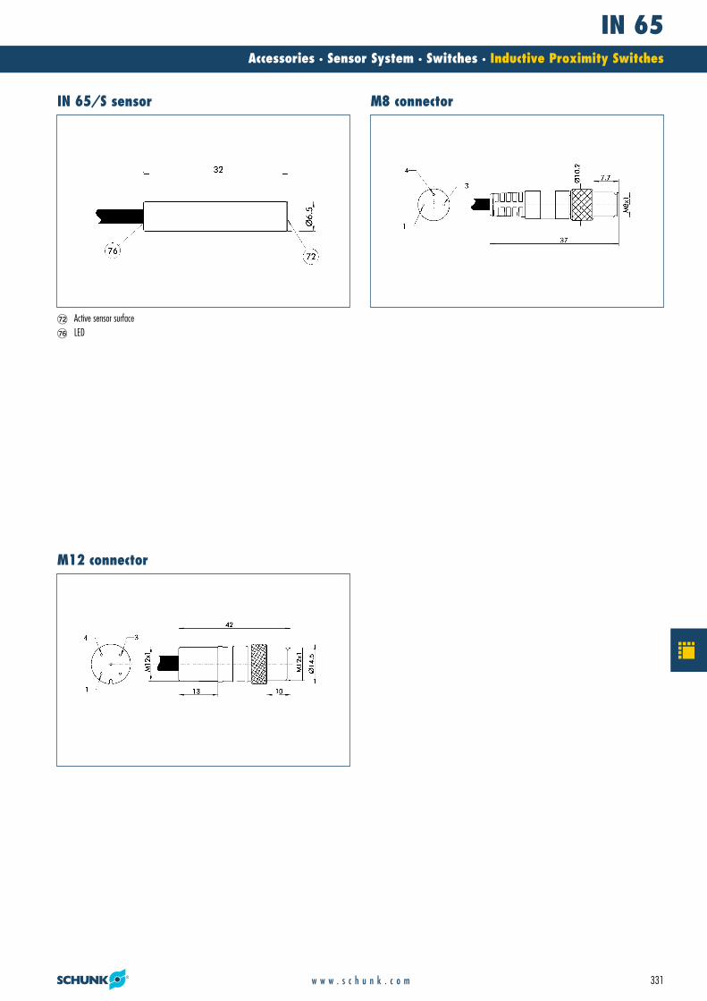
�� Active sensor surface�� LED
IN 65/S sensor M8 connector
M12 connector
21_Zub_Sensorik.qxd:Layout 1 29.04.2008 11:08 Uhr Seite 331

IN 80Accessories · Sensor System · Switches · Inductive Proximity Switches
332 w w w . s c h u n k . c o m
Technical data
Circuit diagram of openerCircuit diagram of closer
1
3
4
1
3
4
Description IN 80-S-M8 IN 80-S-M12 INK 80-S IN 80-O-M8 IN 80-O-M12 INK 80-OID 0301478 0301578 0301550 0301488 0301588 0301551
Switching function Closer Closer Closer Opener Opener OpenerSwitching distance [mm] 1.5 1.5 1.5 1.5 1.5 1.5Hysteresis of nominal switching distance < 15% < 15% < 15% < 15% < 15% < 15%Switching method PNP PNP PNP PNP PNP PNPCable length [cm] 30.0 30.0 200.0 30.0 30.0 200.0Cable connector/cable end M8 M12 Open wire M8 M12 Open wireType of voltage DC DC DC DC DC DCNominal voltage [V] 24.0 24.0 24.0 24.0 24.0 24.0Min. voltage [V] 10.0 10.0 10.0 10.0 10.0 10.0Max. voltage [V] 30.0 30.0 30.0 30.0 30.0 30.0Voltage drop [V] 1.5 1.5 1.5 1.5 1.5 1.5Max. power on contact [A] 0.2 0.2 0.2 0.2 0.2 0.2Min. ambient temperature [°C] -25.0 -25.0 -25.0 -25.0 -25.0 -25.0Max. ambient temperature [°C] 70.0 70.0 70.0 70.0 70.0 70.0Max. switching frequency [Hz] 1000.0 1000.0 1000.0 1000.0 1000.0 1000.0IP class (sensor) 67 67 67 67 67 67IP class (connector, plugged in) 67 67 67 67 67 67LED display on sensor Yes Yes Yes Yes Yes YesCable diameter [mm] 3.5 3.5 3.5 3.5 3.5 3.5Min. bending radius (dynamic) [mm] 35.0 35.0 35.0 35.0 35.0 35.0Min. bending radius (static) [mm] 17.5 17.5 17.5 17.5 17.5 17.5No. of wires 3 3 3 3 3 3Wire cross section [mm2] 0.14 0.14 0.14 0.14 0.14 0.14
21_Zub_Sensorik.qxd:Layout 1 29.04.2008 11:08 Uhr Seite 332

IN 80Accessories · Sensor System · Switches · Inductive Proximity Switches
333w w w . s c h u n k . c o m
�� Active sensor surface�� LED
IN 80 sensor M8 connector
M12 connector
21_Zub_Sensorik.qxd:Layout 1 29.04.2008 11:08 Uhr Seite 333

IN B-80/80SLAccessories · Sensor System · Switches · Inductive Proximity Switches
334 w w w . s c h u n k . c o m
Technical data
Circuit diagram of closer
1
3
4
Description IN 80-SL-M12 INK 80-SLID 0301529 0301579
Switching function Closer CloserSwitching distance [mm] 3.0 3.0Hysteresis of nominal switching distance < 15% < 15%Switching method PNP PNPCable length [cm] 30.0 200.0Cable connector/cable end M12 Open wireType of voltage DC DCNominal voltage [V] 24.0 24.0Min. voltage [V] 10.0 10.0Max. voltage [V] 30.0 30.0Voltage drop [V] 1.5 1.5Max. power on contact [A] 0.2 0.2Min. ambient temperature [°C] -25.0 -25.0Max. ambient temperature [°C] 70.0 70.0Max. switching frequency [Hz] 1000.0 1000.0IP class (sensor) 67 67IP class (connector, plugged in) 67 67LED display on sensor Yes YesCable diameter [mm] 3.5 3.5Min. bending radius (dynamic) [mm] 35.0 35.0Min. bending radius (static) [mm] 17.5 17.5No. of wires/contacts 3 3Wire cross section [mm2] 0.14 0.14
21_Zub_Sensorik.qxd:Layout 1 29.04.2008 11:08 Uhr Seite 334

IN B-80/80SLAccessories · Sensor System · Switches · Inductive Proximity Switches
335w w w . s c h u n k . c o m
�� Active sensor surface�� LED
�� Active sensor surface�� LED
IN B-80 sensor IN 80/SL sensor
21_Zub_Sensorik.qxd:Layout 1 29.04.2008 11:08 Uhr Seite 335

IN 120Accessories · Sensor System · Switches · Inductive Proximity Switches
336 w w w . s c h u n k . c o m
Technical data
Circuit diagram of closer
1
3
4
Description IN 120-S-M12 INK 120-SID 0301592 0301562
Switching function Closer CloserSwitching distance [mm] 2.0 2.0Hysteresis of nominal switching distance < 15% < 15%Switching method PNP PNPCable length [cm] 30.0 200.0Cable connector/cable end M12 Open wireType of voltage DC DCNominal voltage [V] 24.0 24.0Min. voltage [V] 10.0 10.0Max. voltage [V] 30.0 30.0Voltage drop [V] 1.5 1.5Max. power on contact [A] 0.2 0.2Min. ambient temperature [°C] -25.0 -25.0Max. ambient temperature [°C] 70.0 70.0Max. switching frequency [Hz] 1000.0 1000.0IP class (sensor) 67 67IP class (connector, plugged in) 67 67LED display on sensor No NoCable diameter [mm] 3.5 3.5Min. bending radius (dynamic) [mm] 35.0 35.0Min. bending radius (static) [mm] 17.5 17.5No. of wires 3 3Wire cross section [mm2] 0.14 0.14
21_Zub_Sensorik.qxd:Layout 1 29.04.2008 11:08 Uhr Seite 336

IN 120Accessories · Sensor System · Switches · Inductive Proximity Switches
337w w w . s c h u n k . c o m
�� Active sensor surface
IN 120/S sensor M12 connector
21_Zub_Sensorik.qxd:Layout 1 29.04.2008 11:08 Uhr Seite 337

RMSAccessories · Sensor System · Switches · Reed Switches
338 w w w . s c h u n k . c o m
Reed switches consist of tiny, metal contacts (reeds). Under the influence of a magnetic field, they bend and touch one another, closing the contact.
Function descriptionEconomicalfor cost-saving applications
Installed in the sensor slotfor space-saving, simple and fast assembly
Version with connectorfor easy, rapid replacement of the extension cable
Ultra-flexible PUR cablefor a long life and resistance to many chemicals
Your advantages and benefits
Reed Switches
Reed switches are mechanical switches that react to the presence of magnetic fields (magnets). They are frequently used as low-price alternatives to electronic magnetic switches (MMS).
21_Zub_Sensorik.qxd:Layout 1 29.04.2008 11:08 Uhr Seite 338
RMSAccessories · Sensor System · Switches · Reed Switches
339w w w . s c h u n k . c o m
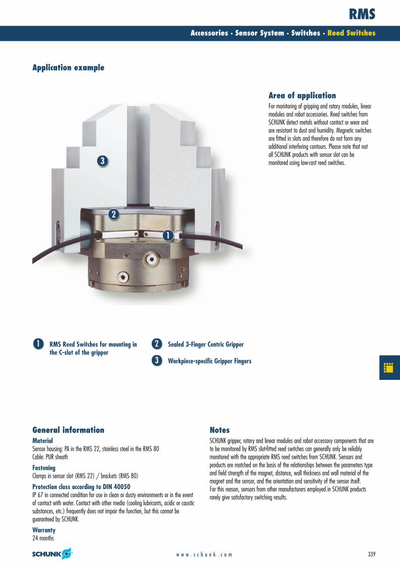
RMS Reed Switches for mounting inthe C-slot of the gripper
Sealed 3-Finger Centric Gripper
Workpiece-specific Gripper Fingers
MaterialSensor housing: PA in the RMS 22, stainless steel in the RMS 80Cable: PUR sheath
FasteningClamps in sensor slot (RMS 22) / brackets (RMS 80)
Protection class according to DIN 40050IP 67 in connected condition for use in clean or dusty environments or in the eventof contact with water. Contact with other media (cooling lubricants, acidic or causticsubstances, etc.) frequently does not impair the function, but this cannot be guaranteed by SCHUNK.
Warranty24 months
General informationSCHUNK gripper, rotary and linear modules and robot accessory components that areto be monitored by RMS slot-fitted reed switches can generally only be reliably monitored with the appropriate RMS reed switches from SCHUNK. Sensors and products are matched on the basis of the relationships between the parameters typeand field strength of the magnet, distance, wall thickness and wall material of themagnet and the sensor, and the orientation and sensitivity of the sensor itself. For this reason, sensors from other manufacturers employed in SCHUNK productsrarely give satisfactory switching results.
Notes
Application example
For monitoring of gripping and rotary modules, linearmodules and robot accessories. Reed switches fromSCHUNK detect metals without contact or wear andare resistant to dust and humidity. Magnetic switchesare fitted in slots and therefore do not form any additional interfering contours. Please note that not all SCHUNK products with sensor slot can be monitored using low-cost reed switches.
Area of application
21_Zub_Sensorik.qxd:Layout 1 29.04.2008 11:08 Uhr Seite 339

RMS 22Accessories · Sensor System · Switches · Reed Switches
340 w w w . s c h u n k . c o m
Technical data
Circuit diagram of closer
1
3
4
Description RMS 22-S-M8ID 0377720
Switching function CloserSwitching method PNP, NPNCable length [cm] 30.0Cable connector/cable end M8Type of voltage DCMax. voltage DC [V] 120.0Voltage drop DC [V] 0.0Max. power on contact DC [A] 0.4Type of voltage ACMax. voltage AC [V] 120.0Voltage drop AC [V] 0.0Max. power on contact AC [A] 0.4Min. ambient temperature [°C] -5.0Max. ambient temperature [°C] 70.0Typical switching time [s] 0.01IP class (sensor) 67IP class (connector, plugged in) 67LED display on sensor NoCable diameter [mm] 2.1Min. bending radius (dynamic) [mm] 21.0Min. bending radius (static) [mm] 10.5No. of wires 2Wire cross section [mm2] 0.14
21_Zub_Sensorik.qxd:Layout 1 29.04.2008 11:08 Uhr Seite 340

RMS 22Accessories · Sensor System · Switches · Reed Switches
341w w w . s c h u n k . c o m
�� Active sensor surface
RMS 22 sensor M8 connector
21_Zub_Sensorik.qxd:Layout 1 29.04.2008 11:08 Uhr Seite 341

RMS 80Accessories · Sensor System · Switches · Reed Switches
342 w w w . s c h u n k . c o m
Technical data
Circuit diagram of closer
1
3
4
Description RMS 80-S-M8ID 0377721
Switching function CloserSwitching method PNP, NPNCable length [cm] 30.0Cable connector/cable end M8Type of voltage DCMax. voltage DC [V] 120.0Voltage drop DC [V] 0.0Max. power on contact DC [A] 0.4Type of voltage ACMax. voltage AC [V] 120.0Voltage drop AC [V] 0.0Max. power on contact AC [A] 0.4Min. ambient temperature [°C] -5.0Max. ambient temperature [°C] 70.0Typical switching time [s] 0.01IP class (sensor) 67IP class (connector, plugged in) 67LED display on sensor NoCable diameter [mm] 2.1Min. bending radius (dynamic) [mm] 21.0Min. bending radius (static) [mm] 10.5No. of wires 2Wire cross section [mm2] 0.14
21_Zub_Sensorik.qxd:Layout 1 29.04.2008 11:08 Uhr Seite 342

RMS 80Accessories · Sensor System · Switches · Reed Switches
343w w w . s c h u n k . c o m
�� Active sensor surface
RMS 80 sensor M8 connector
21_Zub_Sensorik.qxd:Layout 1 29.04.2008 11:08 Uhr Seite 343

MMSAccessories · Sensor System · Switches · Magnetic Switches
344 w w w . s c h u n k . c o m
Magnetic switches react to magnetic fields. The resistors in the sensor consist of several ferromagnetic and non-magnetic layers. Two shielded and two non-shieldedresistors are combined in a bridge circuit, which produces a signal proportional to the magnetic field when one is present. Above a threshold value, an output signal isswitched via a comparator, and the sensor reacts.
Function descriptionInstallation in the sensor slotfor space-saving, simple and fast assembly
Version with LED display (MMS 22)for checking the switching position directly at the sensor
Version with connectorfor easy, rapid replacement of the extension cable
Ultra-flexible PUR cablefor a long life and resistance to many chemicals
Your advantages and benefits
Magnetic Switches
Magnetic switches are used for monitoring the position of automation components. They detect the approach of a magnet without contact and, above a certain switching threshold, enabletheir output.
21_Zub_Sensorik.qxd:Layout 1 29.04.2008 11:08 Uhr Seite 344
MMSAccessories · Sensor System · Switches · Magnetic Switches
345w w w . s c h u n k . c o m
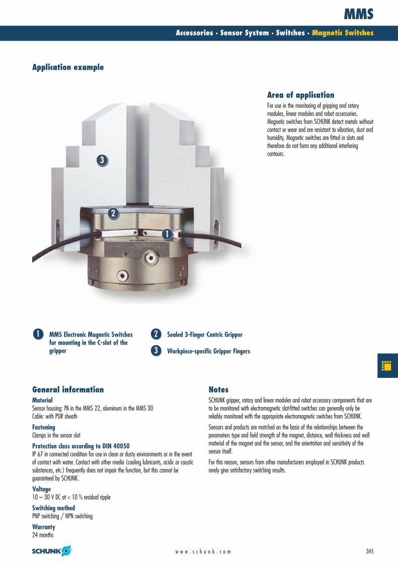
MMS Electronic Magnetic Switchesfor mounting in the C-slot of thegripper
Sealed 3-Finger Centric Gripper
Workpiece-specific Gripper Fingers
MaterialSensor housing: PA in the MMS 22, aluminum in the MMS 30Cable: with PUR sheath
FasteningClamps in the sensor slot
Protection class according to DIN 40050IP 67 in connected condition for use in clean or dusty environments or in the eventof contact with water. Contact with other media (cooling lubricants, acidic or causticsubstances, etc.) frequently does not impair the function, but this cannot be guaranteed by SCHUNK.
Voltage10 – 30 V DC at < 10 % residual ripple
Switching methodPNP switching / NPN switching
Warranty24 months
General informationSCHUNK gripper, rotary and linear modules and robot accessory components that areto be monitored with electromagnetic slot-fitted switches can generally only be reliably monitored with the appropriate electromagnetic switches from SCHUNK.
Sensors and products are matched on the basis of the relationships between theparameters type and field strength of the magnet, distance, wall thickness and wallmaterial of the magnet and the sensor, and the orientation and sensitivity of the sensor itself.
For this reason, sensors from other manufacturers employed in SCHUNK productsrarely give satisfactory switching results.
Notes
Application example
For use in the monitoring of gripping and rotary modules, linear modules and robot accessories. Magnetic switches from SCHUNK detect metals withoutcontact or wear and are resistant to vibration, dust and humidity. Magnetic switches are fitted in slots and therefore do not form any additional interfering contours.
Area of application
21_Zub_Sensorik.qxd:Layout 1 29.04.2008 11:09 Uhr Seite 345

MMS 22Accessories · Sensor System · Switches · Magnetic Switches
346 w w w . s c h u n k . c o m
Technical data
Circuit diagram of NPN closerCircuit diagram of closer
1
3
4
1
3
4
Description MMS 22-S-M5-PNP MMS 22-S-M5-NPN MMS 22-S-M8-PNP MMS 22-S-M8-NPN MMSK 22-S-PNP MMSK 22-S-NPNID 0301438 0301439 0301432 0301433 0301434 0301435
Switching function Closer Closer Closer Closer Closer CloserSwitching method PNP NPN PNP NPN PNP NPNCable length [cm] 30.0 30.0 30.0 30.0 200.0 200.0Cable connector/cable end M5 M5 M8 M8 Open wire Open wireType of voltage DC DC DC DC DC DCNominal voltage [V] 24.0 24.0 24.0 24.0 24.0 24.0Min. voltage [V] 10.0 10.0 10.0 10.0 10.0 10.0Max. voltage [V] 30.0 30.0 30.0 30.0 30.0 30.0Voltage drop [V] 1.5 1.5 1.5 1.5 1.5 1.5Max. power on contact [A] 0.2 0.2 0.2 0.2 0.2 0.2Min. ambient temperature [°C] -10.0 -10.0 -10.0 -10.0 -10.0 -10.0Max. ambient temperature [°C] 70.0 70.0 70.0 70.0 70.0 70.0Typical switching time [s] 0.001 0.001 0.001 0.001 0.001 0.001IP class (sensor) 67 67 67 67 67 67IP class (connector, plugged in) 67 67 67 67 67 67LED display on sensor Yes Yes Yes Yes Yes YesCable diameter [mm] 2.1 2.1 2.1 2.1 2.1 2.1Min. bending radius (dynamic) [mm] 21.0 21.0 21.0 21.0 21.0 21.0Min. bending radius (static) [mm] 10.5 10.5 10.5 10.5 10.5 10.5No. of wires 3 3 3 3 3 3Wire cross section [mm2] 0.14 0.14 0.14 0.14 0.14 0.14
21_Zub_Sensorik.qxd:Layout 1 29.04.2008 11:09 Uhr Seite 346
MMS 22Accessories · Sensor System · Switches · Magnetic Switches
347w w w . s c h u n k . c o m
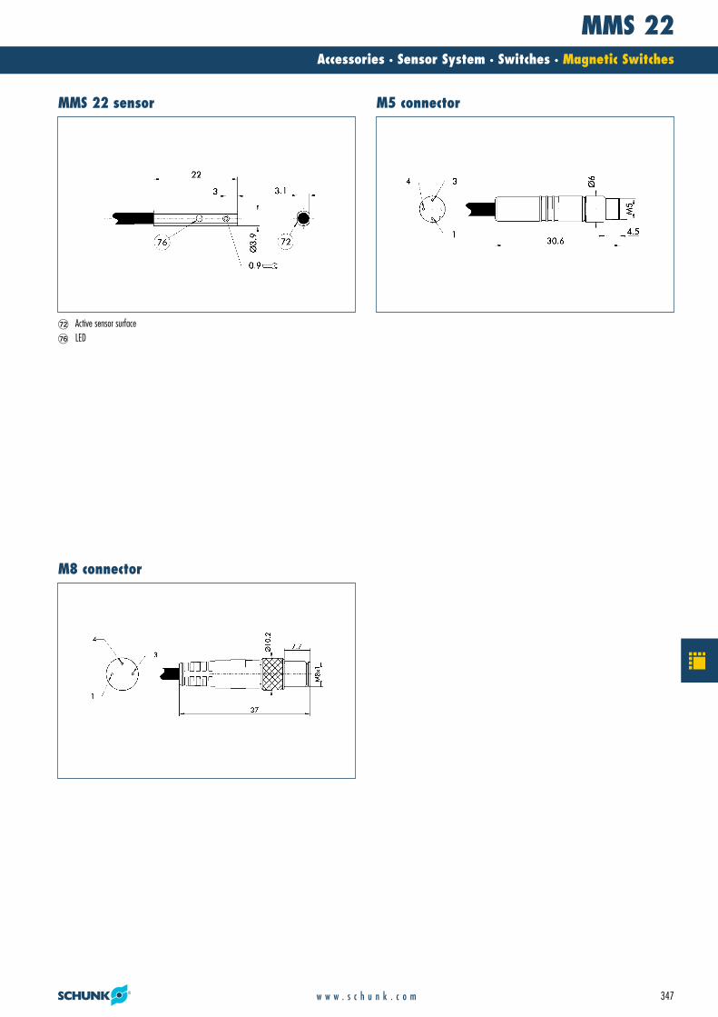
�� Active sensor surface�� LED
MMS 22 sensor M5 connector
M8 connector
21_Zub_Sensorik.qxd:Layout 1 29.04.2008 11:09 Uhr Seite 347

MMS 22-SAAccessories · Sensor System · Switches · Magnetic Switches
348 w w w . s c h u n k . c o m
Technical data
Circuit diagram of NPN closerCircuit diagram of closer
1
3
4
1
3
4
Description MMS 22-S-M5-PNP-SA MMS 22-S-M5-NPN-SA MMS 22-S-M8-PNP-SA MMS 22-S-M8-NPN-SA MMSK 22-S-PNP-SA MMSK 22-S-NPN-SAID 0301448 0301449 0301442 0301443 0301444 0301445
Switching function Closer Closer Closer Closer Closer CloserSwitching method PNP NPN PNP NPN PNP NPNCable length [cm] 30.0 30.0 30.0 30.0 200.0 200.0Cable connector/cable end M5 M5 M8 M8 Open wire Open wireType of voltage DC DC DC DC DC DCNominal voltage [V] 24.0 24.0 24.0 24.0 24.0 24.0Min. voltage [V] 10.0 10.0 10.0 10.0 10.0 10.0Max. voltage [V] 30.0 30.0 30.0 30.0 30.0 30.0Voltage drop [V] 1.5 1.5 1.5 1.5 1.5 1.5Max. power on contact [A] 0.2 0.2 0.2 0.2 0.2 0.2Min. ambient temperature [°C] -10.0 -10.0 -10.0 -10.0 -10.0 -10.0Max. ambient temperature [°C] 70.0 70.0 70.0 70.0 70.0 70.0Typical switching time [s] 0.001 0.001 0.001 0.001 0.001 0.001IP class (sensor) 67 67 67 67 67 67IP class (connector, plugged in) 67 67 67 67 67 67LED display on sensor Yes Yes Yes Yes Yes YesCable diameter [mm] 2.1 2.1 2.1 2.1 2.1 2.1Min. bending radius (dynamic) [mm] 21.0 21.0 21.0 21.0 21.0 21.0Min. bending radius (static) [mm] 10.5 10.5 10.5 10.5 10.5 10.5No. of wires 3 3 3 3 3 3Wire cross section [mm2] 0.14 0.14 0.14 0.14 0.14 0.14
21_Zub_Sensorik.qxd:Layout 1 29.04.2008 11:09 Uhr Seite 348
MMS 22-SAAccessories · Sensor System · Switches · Magnetic Switches
349w w w . s c h u n k . c o m
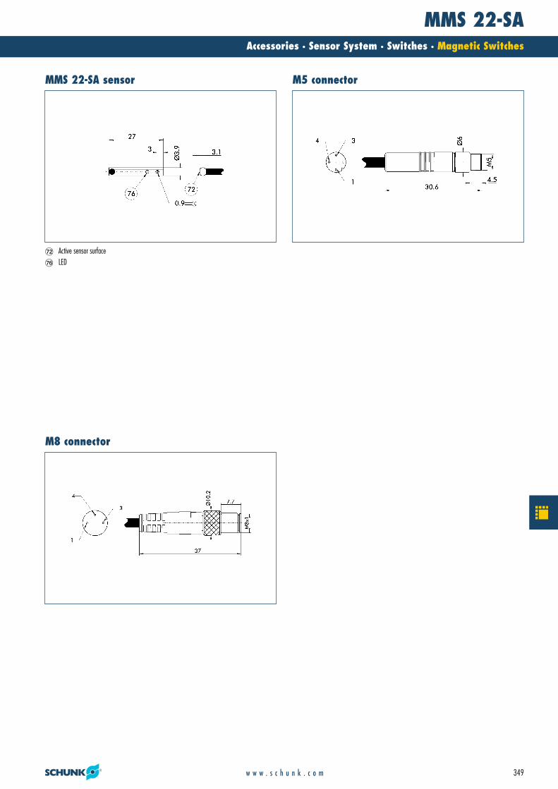
�� Active sensor surface�� LED
MMS 22-SA sensor M5 connector
M8 connector
21_Zub_Sensorik.qxd:Layout 1 29.04.2008 11:09 Uhr Seite 349
MMS 30Accessories · Sensor System · Switches · Magnetic Switches
350 w w w . s c h u n k . c o m
Technical data
1
3
4
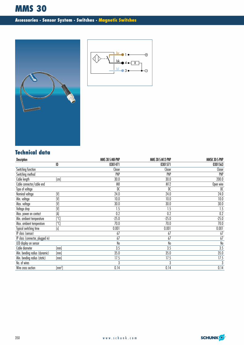
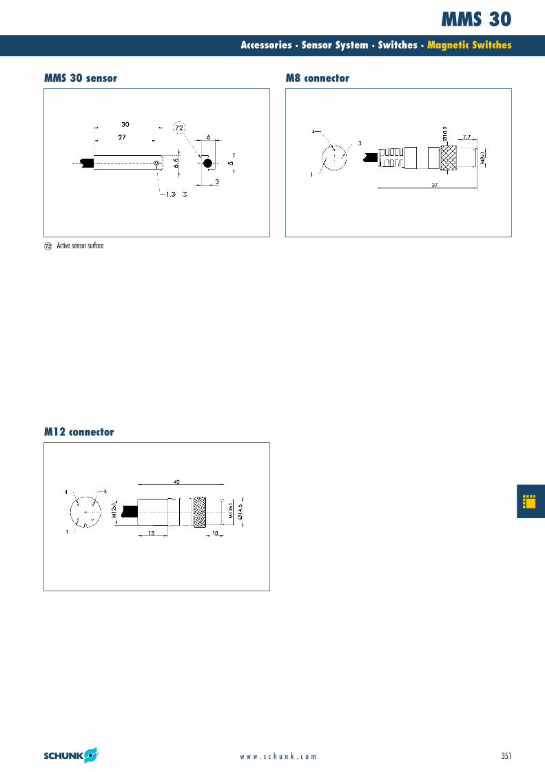
Description MMS 30-S-M8-PNP MMS 30-S-M12-PNP MMSK 30-S-PNPID 0301471 0301571 0301563
Switching function Closer Closer CloserSwitching method PNP PNP PNPCable length [cm] 30.0 30.0 200.0Cable connector/cable end M8 M12 Open wireType of voltage DC DC DCNominal voltage [V] 24.0 24.0 24.0Min. voltage [V] 10.0 10.0 10.0Max. voltage [V] 30.0 30.0 30.0Voltage drop [V] 1.5 1.5 1.5Max. power on contact [A] 0.2 0.2 0.2Min. ambient temperature [°C] -25.0 -25.0 -25.0Max. ambient temperature [°C] 70.0 70.0 70.0Typical switching time [s] 0.001 0.001 0.001IP class (sensor) 67 67 67IP class (connector, plugged in) 67 67 67LED display on sensor No No NoCable diameter [mm] 3.5 3.5 3.5Min. bending radius (dynamic) [mm] 35.0 35.0 35.0Min. bending radius (static) [mm] 17.5 17.5 17.5No. of wires 3 3 3Wire cross section [mm2] 0.14 0.14 0.14
21_Zub_Sensorik.qxd:Layout 1 29.04.2008 11:09 Uhr Seite 350
MMS 30Accessories · Sensor System · Switches · Magnetic Switches
351w w w . s c h u n k . c o m
�� Active sensor surface
MMS 30 sensor M8 connector
M12 connector
21_Zub_Sensorik.qxd:Layout 1 29.04.2008 11:09 Uhr Seite 351

MMSK 65Accessories · Sensor System · Switches · Magnetic Switches
352 w w w . s c h u n k . c o m
Circuit diagram of NPN closerCircuit diagram of closer
1
3
4
1
3
4
Description MMS-K 65-5-PNP MMS-K 65-5-NPNID 0301423 0301424
Switching function Closer CloserSwitching method PNP NPNCable length [cm] 20.0 20.0Type of voltage DC DCNominal voltage [V] 24.0 24.0Min. voltage [V] 10.0 10.0Max. voltage [V] 30.0 30.0Max. power on contact [A] 0.2 0.2Min. ambient temperature [°C] -20.0 -20.0Max. ambient temperature [°C] 70.0 70.0IP class (sensor) 67 67IP class (connector, plugged in) 67 67No. of wires 3 3Wire cross section [mm2] 0.14 0.14
21_Zub_Sensorik.qxd:Layout 1 29.04.2008 11:09 Uhr Seite 352

MMSK 65Accessories · Sensor System · Switches · Magnetic Switches
353w w w . s c h u n k . c o m
�� Active sensor surface
MMSK 65/S sensor
21_Zub_Sensorik.qxd:Layout 1 29.04.2008 11:09 Uhr Seite 353

ONSAccessories · Sensor System · Switches · Optical Switch
354 w w w . s c h u n k . c o m
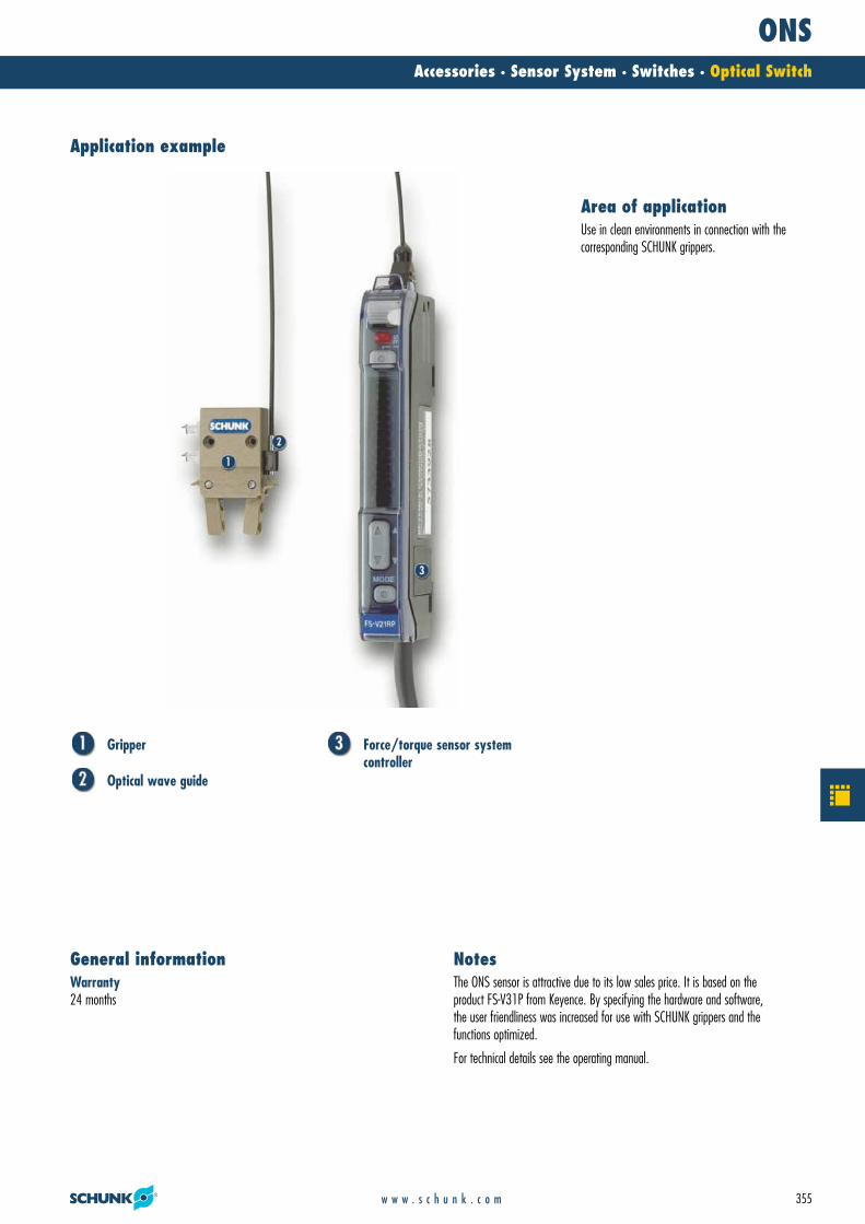
The optical sensor ONS emits light via the optical wave guide ONS-LWL. By analyzingthe quantity of reflected light, the ONS can detect positions of the gripper beingmonitored and set or delete its output based on the programming.
Function descriptionEasy programmingfor short commissioning times
LED displayfor fast and easy functional checks
Light optical wave guidefor low weight on the gripper
Your advantages and benefits
Optical switch
21_Zub_Sensorik.qxd:Layout 1 29.04.2008 11:09 Uhr Seite 354
ONSAccessories · Sensor System · Switches · Optical Switch
355w w w . s c h u n k . c o m
Gripper
Optical wave guide
Force/torque sensor system controller
Warranty24 months
General informationThe ONS sensor is attractive due to its low sales price. It is based on the product FS-V31P from Keyence. By specifying the hardware and software, the user friendliness was increased for use with SCHUNK grippers and thefunctions optimized.
For technical details see the operating manual.
Notes
Application example
Use in clean environments in connection with the corresponding SCHUNK grippers.
Area of application
21_Zub_Sensorik.qxd:Layout 1 29.04.2008 11:09 Uhr Seite 355

ONS 01Accessories · Sensor System · Switches · Optical Switch
356 w w w . s c h u n k . c o m
Technical data
Description ONS 01ID 0301390
Voltage supply DCMin. voltage [V] 12Max. voltage [V] 24Number of digital switching outputs 1Max. power on contact [mA] 100Min. ambient temperature [°C] -10Max. ambient temperature [°C] 55IP class 20
Description ONS 01-LWLID 0301391
Cable diameter [mm] 1Diameter ob cable end [mm] 1.5Cable length [m] 1Min. bending radius (dynamic) [mm] 40Min. bending radius (static) [mm] 30
21_Zub_Sensorik.qxd:Layout 1 29.04.2008 11:09 Uhr Seite 356

ONS 01Accessories · Sensor System · Switches · Optical Switch
357w w w . s c h u n k . c o m
� One optical wave guide ONS 01-LWL is needed for each ONS 01.
�� Active sensor surface
Main views of the ONS 01
�$ Assembly rail�� Connection for sensor
ONS 01-LWL
21_Zub_Sensorik.qxd:Layout 1 29.04.2008 11:09 Uhr Seite 357

SSTAccessories · Sensor System · Switches · Switch Accessories
358 w w w . s c h u n k . c o m
The sensor is connected to the M8 - M12 or terminal connection of the sensor testerand the ON button pressed. The sensor position is displayed visually by LEDs and output acoustically via a signal buzzer.
Function descriptionVisual and acoustic signalfor simple function checking and adjustment
For 2 and 3-wire DC technologyenabling the connection of reed contacts, capacitive and inductive sensors
Tests possible without dismantling sensorsfor short maintenance times
Connections for M8 and M12 or open cable ends possibleensuring suitability for all SCHUNK sensors
PNP and NPN sensors can be tested
Operating voltage with 9 V compound batteryfor mobile use
Automatic cut-off functionfor an extended battery life
Your advantages and benefits
Sensor Tester
The SST sensor tester enables the rapid testing and adjustment of inductive sensors, magnetic switches and reed contacts. The necessary power is supplied by a 9 V compound battery.
21_Zub_Sensorik.qxd:Layout 1 29.04.2008 11:09 Uhr Seite 358

SSTAccessories · Sensor System · Switches · Switch Accessories
359w w w . s c h u n k . c o m
Sensor tester SST
Inductive proximity switches IN 80
Metal plate
Scope of deliverySensor tester incl. assembly and operating manual with manufacturer’s declaration, 9 V compound battery
General informationPlease note that only one SST input (M8 or M12 or cable terminal input) can be used at once.
If the toggle switch is towards the sticker (nameplate), PNP is selected, if not, NPN.
Notes
Application example
Sensor testing and adjustment of the switching point(sensor calibration)
Area of application
21_Zub_Sensorik.qxd:Layout 1 29.04.2008 11:09 Uhr Seite 359

SSTAccessories · Sensor System · Switches · Switch Accessories
360 w w w . s c h u n k . c o m
Technical dataDescription SST
ID 0301400Battery 9 V DC (compound battery Type LR 61)Connection 1 M12*1Connection 2 M8*1Connection 3 direct clampingHousing material plasticIP class 20
21_Zub_Sensorik.qxd:Layout 1 29.04.2008 11:09 Uhr Seite 360
SSTAccessories · Sensor System · Switches · Switch Accessories
361w w w . s c h u n k . c o m
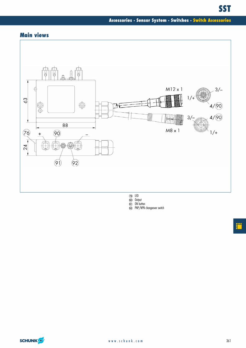
Main views
�� LED�$ Output�� ON button�� PNP/NPN changeover switch
21_Zub_Sensorik.qxd:Layout 1 29.04.2008 11:10 Uhr Seite 361

NHGAccessories · Sensor System · Switches · Switch Accessories
362 w w w . s c h u n k . c o m
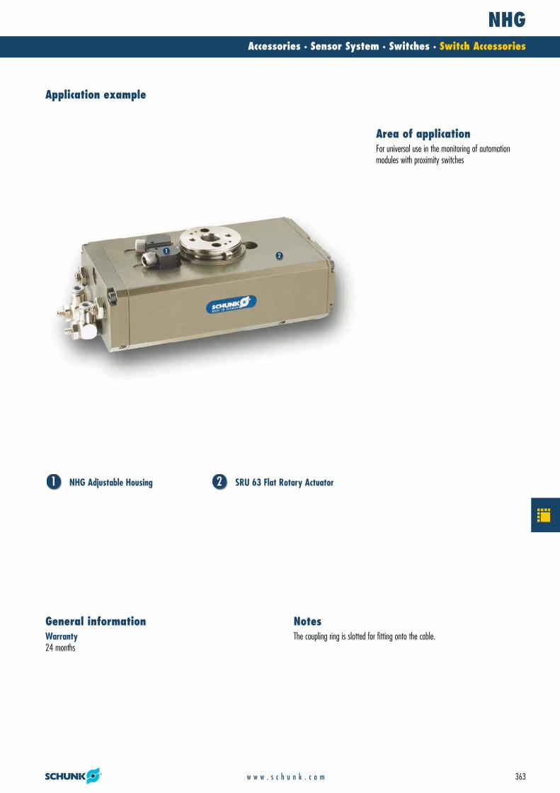
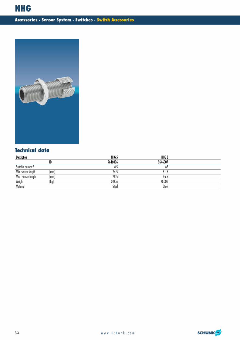
The sensor is inserted in the adjustable housing and fastened with the coupling ring.Next, the switching position is set. When the sensor is changed, the adjustable housing remains in the same location – only the sensor is changed by removing the coupling ring.
Function descriptionSetting has to be carried out only oncefor rapid sensor replacement without recalibration
Corrosion-free materialfor a long service life
Switches are protected against shockspreventing mechanical destruction
Your advantages and benefits
Adjustable housing for proximity switch
The adjustable housings enable the position of the sensor to be set once only. If the sensor is changed, the sensor position is retained.
21_Zub_Sensorik.qxd:Layout 1 29.04.2008 11:10 Uhr Seite 362
NHGAccessories · Sensor System · Switches · Switch Accessories
363w w w . s c h u n k . c o m
NHG Adjustable Housing SRU 63 Flat Rotary Actuator
Warranty24 months
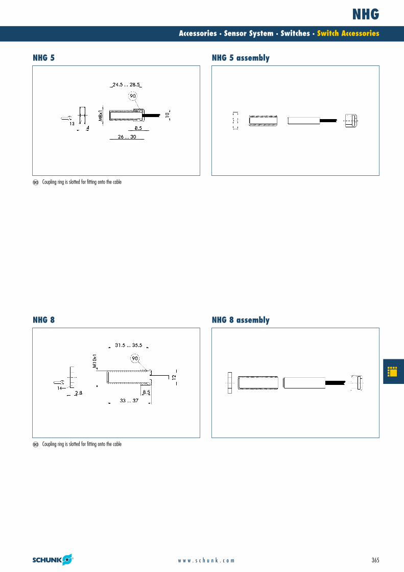
General informationThe coupling ring is slotted for fitting onto the cable.
Notes
Application example
For universal use in the monitoring of automationmodules with proximity switches
Area of application
21_Zub_Sensorik.qxd:Layout 1 29.04.2008 11:10 Uhr Seite 363
NHGAccessories · Sensor System · Switches · Switch Accessories
364 w w w . s c h u n k . c o m
Technical dataDescription NHG 5 NHG 8
ID 9646006 9646007Suitable sensor Ø M5 M8Min. sensor length [mm] 24.5 31.5Max. sensor length [mm] 28.5 35.5Weight [kg] 0.006 0.008Material Steel Steel
21_Zub_Sensorik.qxd:Layout 1 29.04.2008 11:10 Uhr Seite 364
NHGAccessories · Sensor System · Switches · Switch Accessories
365w w w . s c h u n k . c o m
�$ Coupling ring is slotted for fitting onto the cable
�$ Coupling ring is slotted for fitting onto the cable
NHG 5 NHG 5 assembly
NHG 8 NHG 8 assembly
21_Zub_Sensorik.qxd:Layout 1 29.04.2008 11:10 Uhr Seite 365
VAccessories · Sensor System · Distributors · Sensor Distributor
366 w w w . s c h u n k . c o m
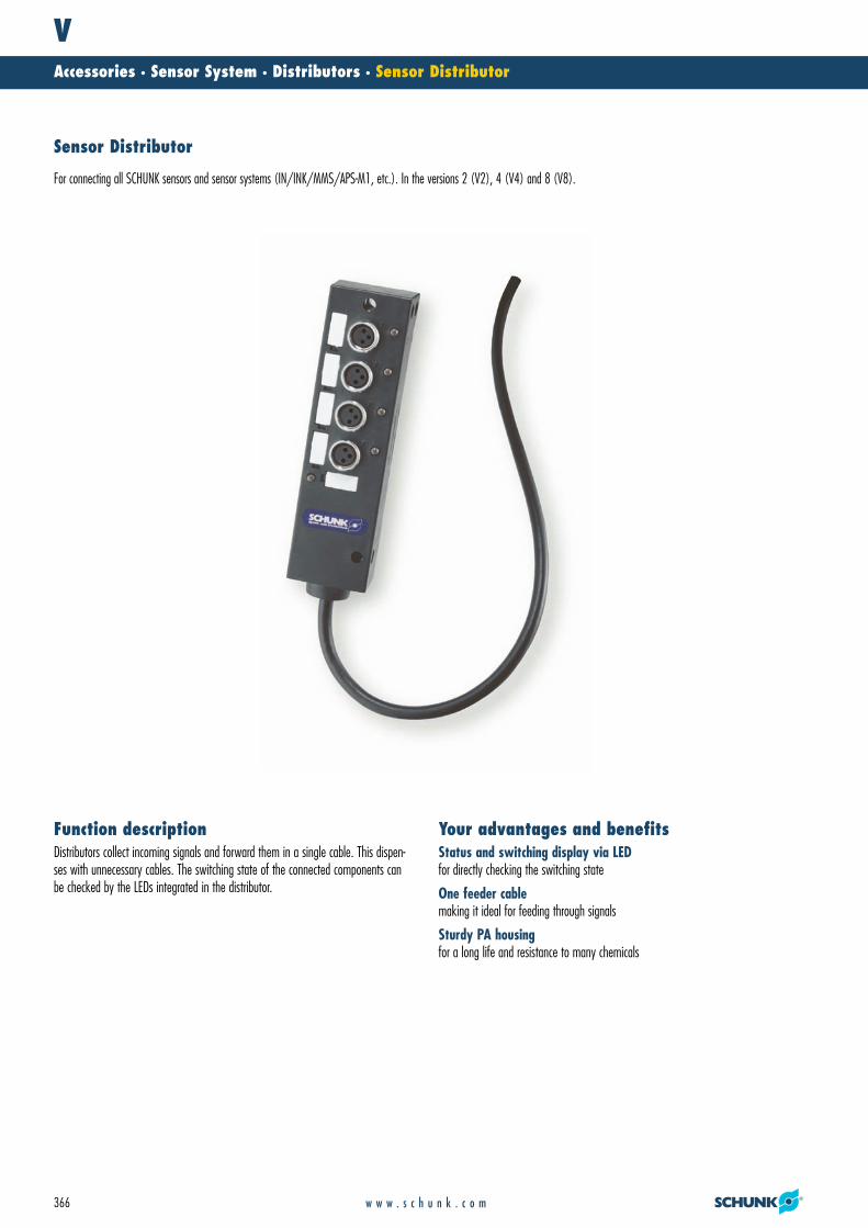
Distributors collect incoming signals and forward them in a single cable. This dispen-ses with unnecessary cables. The switching state of the connected components canbe checked by the LEDs integrated in the distributor.
Function descriptionStatus and switching display via LEDfor directly checking the switching state
One feeder cablemaking it ideal for feeding through signals
Sturdy PA housingfor a long life and resistance to many chemicals
Your advantages and benefits
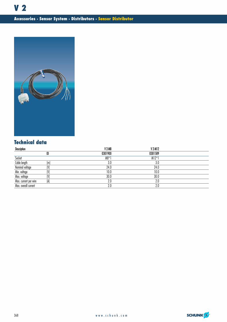
Sensor Distributor
For connecting all SCHUNK sensors and sensor systems (IN/INK/MMS/APS-M1, etc.). In the versions 2 (V2), 4 (V4) and 8 (V8).
21_Zub_Sensorik.qxd:Layout 1 29.04.2008 11:10 Uhr Seite 366
VAccessories · Sensor System · Distributors · Sensor Distributor
367w w w . s c h u n k . c o m
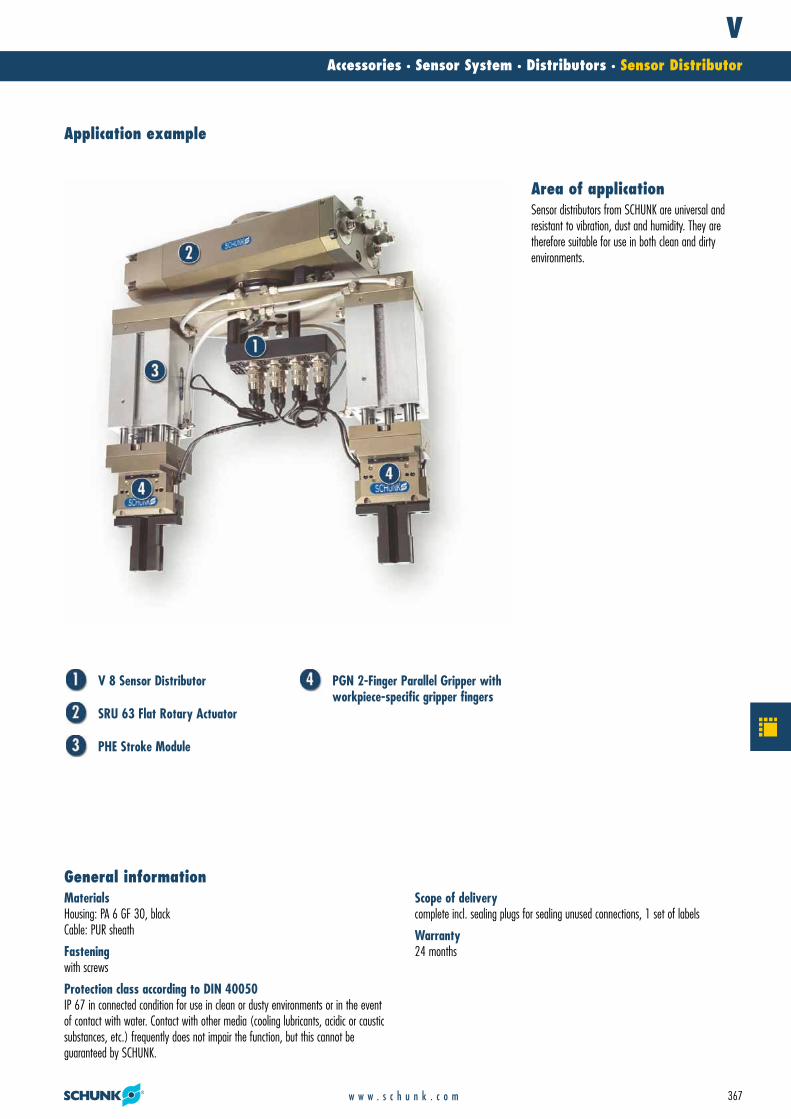
V 8 Sensor Distributor
SRU 63 Flat Rotary Actuator
PHE Stroke Module
PGN 2-Finger Parallel Gripper withworkpiece-specific gripper fingers
MaterialsHousing: PA 6 GF 30, blackCable: PUR sheath
Fasteningwith screws
Protection class according to DIN 40050IP 67 in connected condition for use in clean or dusty environments or in the eventof contact with water. Contact with other media (cooling lubricants, acidic or causticsubstances, etc.) frequently does not impair the function, but this cannot be guaranteed by SCHUNK.
General informationScope of deliverycomplete incl. sealing plugs for sealing unused connections, 1 set of labels
Warranty24 months
Application example
Sensor distributors from SCHUNK are universal andresistant to vibration, dust and humidity. They are therefore suitable for use in both clean and dirty environments.
Area of application
21_Zub_Sensorik.qxd:Layout 1 29.04.2008 11:10 Uhr Seite 367
V 2Accessories · Sensor System · Distributors · Sensor Distributor
368 w w w . s c h u n k . c o m
Technical dataDescription V 2-M8 V 2-M12
ID 0301900 0301589Socket M8*1 M12*1Cable length [m] 3.0 3.0Nominal voltage [V] 24.0 24.0Min. voltage [V] 10.0 10.0Max. voltage [V] 30.0 30.0Max. current per wire [A] 2.0 2.0Max. overall current 2.0 2.0
21_Zub_Sensorik.qxd:Layout 1 29.04.2008 11:10 Uhr Seite 368
V 2Accessories · Sensor System · Distributors · Sensor Distributor
369w w w . s c h u n k . c o m
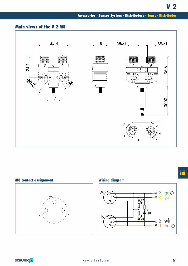
Main views of the V 2-M8
3 gn -4 ye
2 wh1 br +
y
y4A
1
3
41
3B
Wiring diagramM8 contact assignment
21_Zub_Sensorik.qxd:Layout 1 29.04.2008 11:10 Uhr Seite 369

V 2Accessories · Sensor System · Distributors · Sensor Distributor
370 w w w . s c h u n k . c o m
Main views of the V 2-M12
3 gn -4 ye
2 wh1 br +
y
y
B
A4
1
3
4
1
3
Wiring diagramM12 contact assignment
21_Zub_Sensorik.qxd:Layout 1 29.04.2008 11:10 Uhr Seite 370

V 2Accessories · Sensor System · Distributors · Sensor Distributor
371w w w . s c h u n k . c o m
21_Zub_Sensorik.qxd:Layout 1 29.04.2008 11:10 Uhr Seite 371

V 4Accessories · Sensor System · Distributors · Sensor Distributor
372 w w w . s c h u n k . c o m
Technical dataDescription V 4-M5 V 4-M8 V 4-M12
ID 0301661 0301904 0301902Socket M5*1 M8*1 M12*1Cable length [m] 3.0 3.0 3.0Nominal voltage [V] 24.0 24.0 24.0Min. voltage [V] 10.0 10.0 10.0Max. voltage [V] 30.0 30.0 30.0Max. current per wire [A] 2.0 2.0 2.0Max. overall current 2.0 2.0 2.0
21_Zub_Sensorik.qxd:Layout 1 29.04.2008 11:10 Uhr Seite 372
V 4Accessories · Sensor System · Distributors · Sensor Distributor
373w w w . s c h u n k . c o m
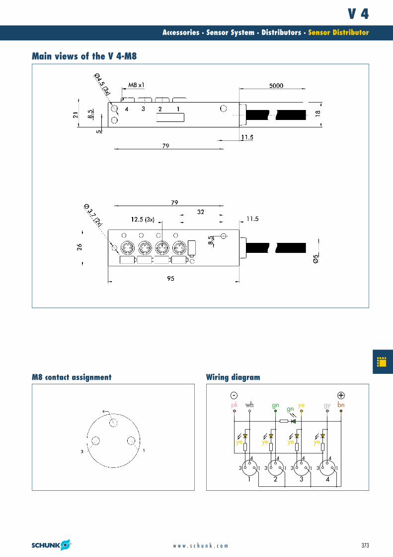
Main views of the V 4-M8
13
4
gn
ye ye ye ye
gn gy bnyewh
13
4
13
4
13
4
1 2 3 4
- +pk
Wiring diagramM8 contact assignment
21_Zub_Sensorik.qxd:Layout 1 29.04.2008 11:10 Uhr Seite 373
V 4Accessories · Sensor System · Distributors · Sensor Distributor
374 w w w . s c h u n k . c o m
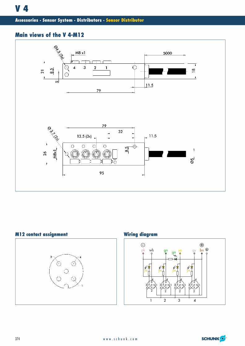
Main views of the V 4-M12
1
2
3
4
gn
ye ye ye ye
gn gy bnyewh
1
2
3
4
1
2
3
4
1
255553
4
1 2 3 4
- +pk
Wiring diagramM12 contact assignment
21_Zub_Sensorik.qxd:Layout 1 29.04.2008 11:10 Uhr Seite 374

V 4Accessories · Sensor System · Distributors · Sensor Distributor
375w w w . s c h u n k . c o m
21_Zub_Sensorik.qxd:Layout 1 29.04.2008 11:11 Uhr Seite 375
V 8Accessories · Sensor System · Distributors · Sensor Distributor
376 w w w . s c h u n k . c o m
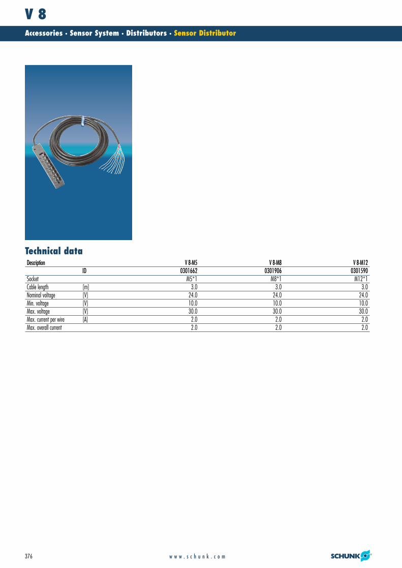
Technical dataDescription V 8-M5 V 8-M8 V 8-M12
ID 0301662 0301906 0301590Socket M5*1 M8*1 M12*1Cable length [m] 3.0 3.0 3.0Nominal voltage [V] 24.0 24.0 24.0Min. voltage [V] 10.0 10.0 10.0Max. voltage [V] 30.0 30.0 30.0Max. current per wire [A] 2.0 2.0 2.0Max. overall current 2.0 2.0 2.0
21_Zub_Sensorik.qxd:Layout 1 29.04.2008 11:11 Uhr Seite 376
V 8Accessories · Sensor System · Distributors · Sensor Distributor
377w w w . s c h u n k . c o m
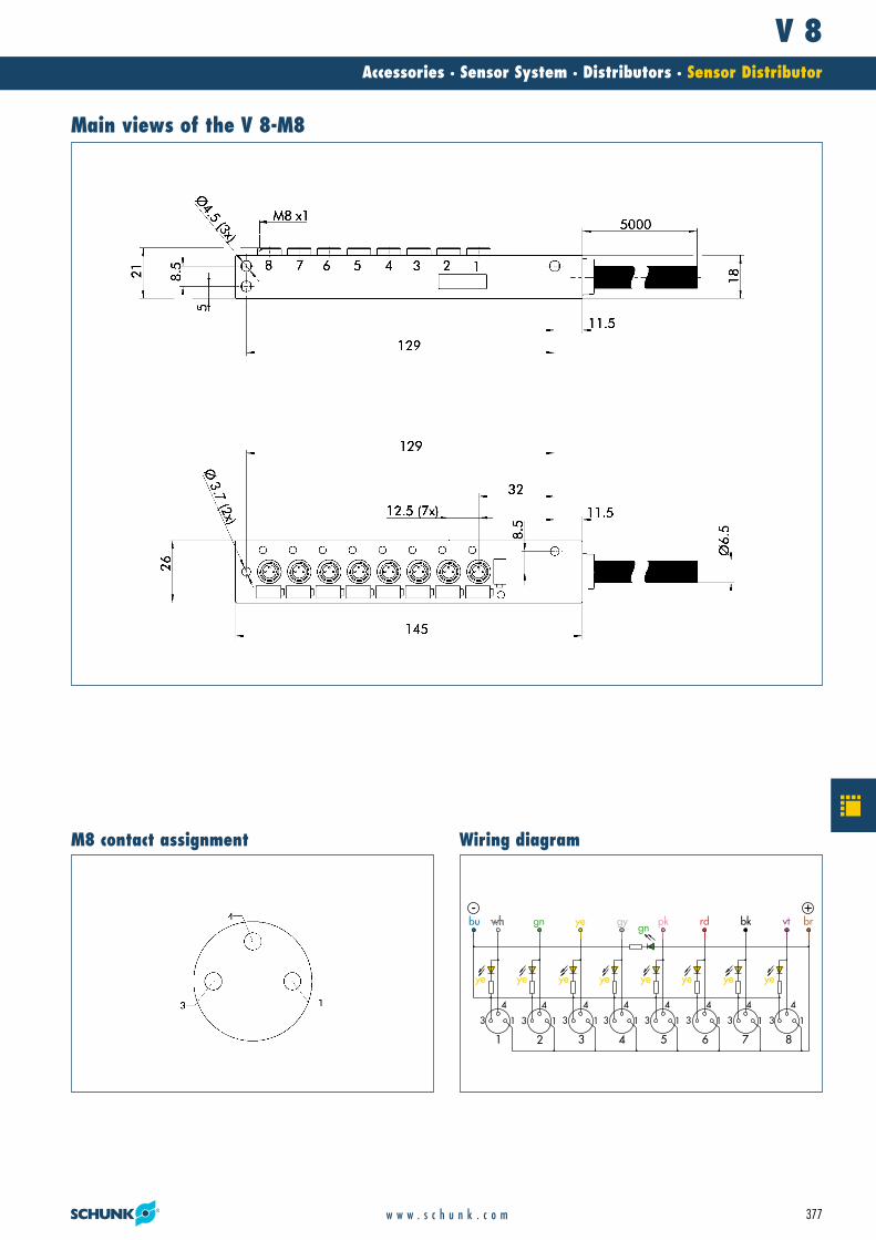
Main views of the V 8-M8
ye ye ye ye ye ye ye ye
bu gn gnye gy pk rd bk vt brwh
6 7 851 2 3 4
3 3 333 3 3 3 1 1 111 1 1 1
4 4 444 4 4 4
- +
Wiring diagramM8 contact assignment
21_Zub_Sensorik.qxd:Layout 1 29.04.2008 11:11 Uhr Seite 377
V 8Accessories · Sensor System · Distributors · Sensor Distributor
378 w w w . s c h u n k . c o m
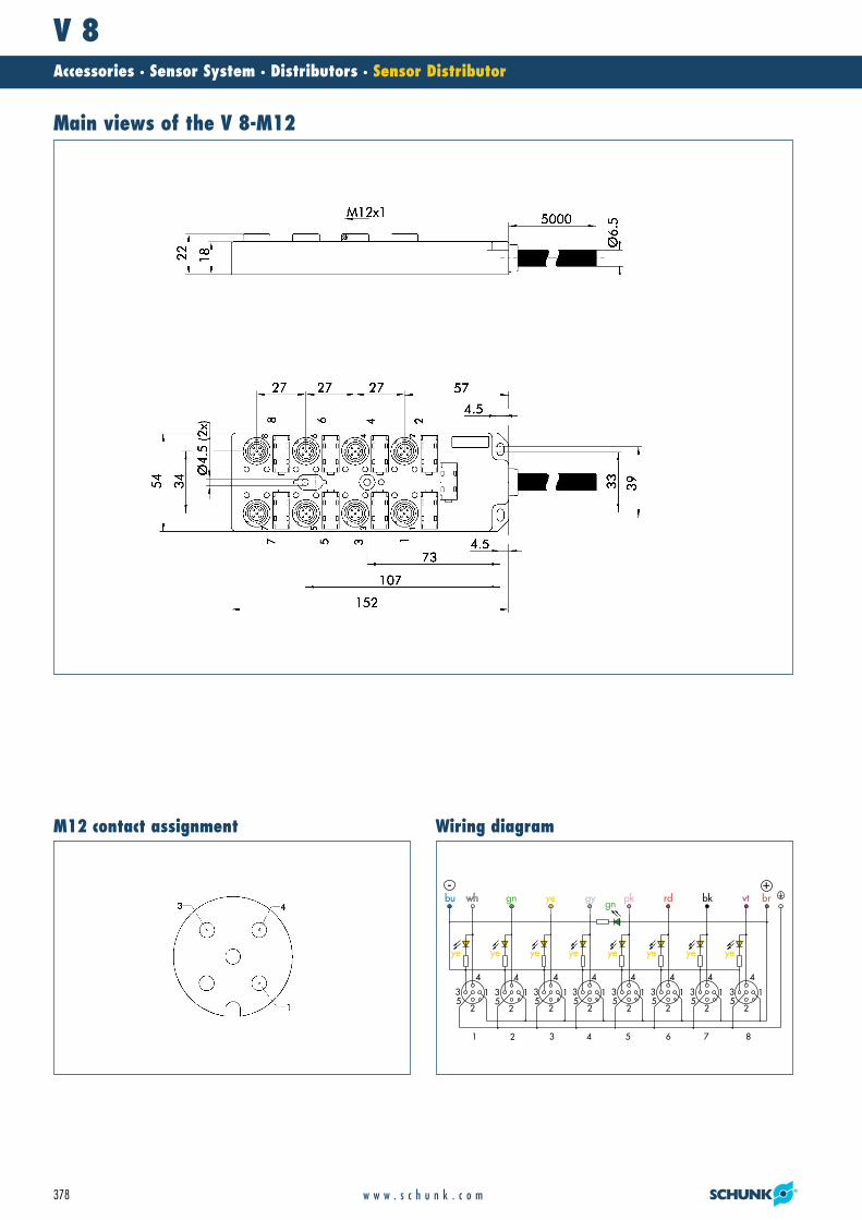
Main views of the V 8-M12
ye ye ye ye ye ye ye ye
bu gn gnye gy pk rd bk vt brwh
6 7 851 2 3 4
3 3 333 3 3 35 5 555 5 5 5
1 1 111 1 1 1
2 2 222 2 2 2
4 4 444 4 4 4
- +
Wiring diagramM12 contact assignment
21_Zub_Sensorik.qxd:Layout 1 29.04.2008 11:11 Uhr Seite 378

V 8Accessories · Sensor System · Distributors · Sensor Distributor
379w w w . s c h u n k . c o m
21_Zub_Sensorik.qxd:Layout 1 29.04.2008 11:11 Uhr Seite 379

Cable/ConnectorAccessories · Sensor System · Cable/Connector for Sensors and Distributors
380 w w w . s c h u n k . c o m
Extensive accessoriesfor special installation environments
Your advantages and benefits
Cable and Connector
Extension cable, and customer cable connectors and sockets allowing convection, for flexible connection of SCHUNK sensor products.
21_Zub_Sensorik.qxd:Layout 1 29.04.2008 11:11 Uhr Seite 380

Cable/ConnectorAccessories · Sensor System · Cable/Connector for Sensors and Distributors
381w w w . s c h u n k . c o m
Cable extension KV
Inductive proximity switches IN
V 2 Sensor Distributor
V 4 Sensor Distributor
Warranty24 months
General information
Application example
variable cable installations
Area of application
21_Zub_Sensorik.qxd:Layout 1 29.04.2008 11:11 Uhr Seite 381
KVAccessories · Sensor System · Cable/Connector for Sensors and Distributors · Cable Extensions
382 w w w . s c h u n k . c o m
Technical data
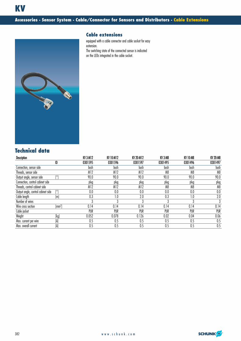
Cable extensionsequipped with a cable connector and cable socket for easyextension.The switching state of the connected sensor is indicatedon the LEDs integrated in the cable socket.
Description KV 3-M12 KV 10-M12 KV 20-M12 KV 3-M8 KV 10-M8 KV 20-M8ID 0301595 0301596 0301597 0301495 0301496 0301497
Connection, sensor side bush bush bush bush bush bushThreads, sensor side M12 M12 M12 M8 M8 M8Output angle, sensor side [°] 90.0 90.0 90.0 90.0 90.0 90.0Connection, control cabinet side plug plug plug plug plug plugThreads, control cabinet side M12 M12 M12 M8 M8 M8Output angle, control cabinet side [°] 0.0 0.0 0.0 0.0 0.0 0.0Cable length [m] 0.3 1.0 2.0 0.3 1.0 2.0Number of wires 3 3 3 3 3 3Wire cross section [mm2] 0.14 0.14 0.14 0.14 0.14 0.14Cable jacket PUR PUR PUR PUR PUR PURWeight [kg] 0.052 0.078 0.126 0.02 0.04 0.06Max. current per wire [A] 0.5 0.5 0.5 0.5 0.5 0.5Max. overall current [A] 0.5 0.5 0.5 0.5 0.5 0.5
21_Zub_Sensorik.qxd:Layout 1 29.04.2008 11:11 Uhr Seite 382

KVAccessories · Sensor System · Cable/Connector for Sensors and Distributors · Cable Extensions
383w w w . s c h u n k . c o m
�� Cable length�� LED
�� Cable length�� LED
KV-M8 KV-M12
21_Zub_Sensorik.qxd:Layout 1 29.04.2008 11:11 Uhr Seite 383
WKAccessories · Sensor System · Cable/Connector for Sensors and Distributors · Supply Cable
384 w w w . s c h u n k . c o m
Technical data
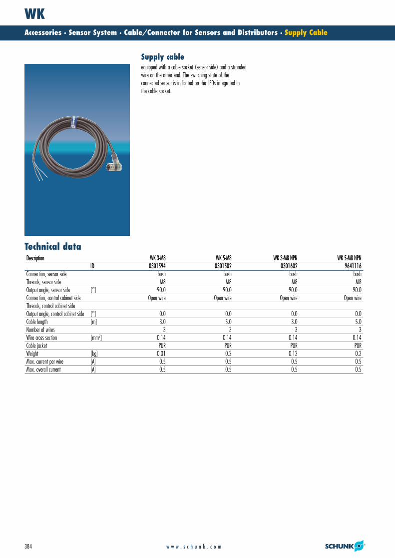
Supply cableequipped with a cable socket (sensor side) and a strandedwire on the other end. The switching state of the connected sensor is indicated on the LEDs integrated inthe cable socket.
Description WK 3-M8 WK 5-M8 WK 3-M8 NPN WK 5-M8 NPNID 0301594 0301502 0301602 9641116
Connection, sensor side bush bush bush bushThreads, sensor side M8 M8 M8 M8Output angle, sensor side [°] 90.0 90.0 90.0 90.0Connection, control cabinet side Open wire Open wire Open wire Open wireThreads, control cabinet sideOutput angle, control cabinet side [°] 0.0 0.0 0.0 0.0Cable length [m] 3.0 5.0 3.0 5.0Number of wires 3 3 3 3Wire cross section [mm2] 0.14 0.14 0.14 0.14Cable jacket PUR PUR PUR PURWeight [kg] 0.01 0.2 0.12 0.2Max. current per wire [A] 0.5 0.5 0.5 0.5Max. overall current [A] 0.5 0.5 0.5 0.5
21_Zub_Sensorik.qxd:Layout 1 29.04.2008 11:11 Uhr Seite 384
WKAccessories · Sensor System · Cable/Connector for Sensors and Distributors · Supply Cable
385w w w . s c h u n k . c o m
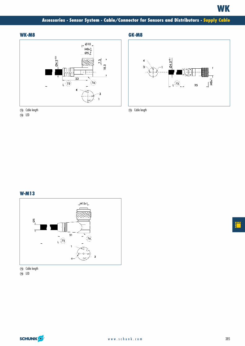
�� Cable length�� LED
�� Cable length�� Cable length�� LED
WK-M8 GK-M8
W-M13
21_Zub_Sensorik.qxd:Layout 1 29.04.2008 11:11 Uhr Seite 385

KST-M8/KBU-M8Accessories · Sensor System · Cable/Connector for Sensors and Distributors · Cable Connector and Socket
386 w w w . s c h u n k . c o m
Technical data
Cable connector and socketcan be connected directly to cables. Cable connectors/sockets with M8 connection are soldered to the cable;cable connectors/sockets with M12 connection are connected via clamping.
Description KST-M8-G KST-M8-W KBU-M8-G KBU-M8-WID 0300050 0300051 0300052 0300053
Connection 3-pin 3-pin 3-pin 3-pinMaximum voltage [V] 60 AC / 75 DC 60 AC / 75 DC 60 AC / 75 DC 60 AC / 75 DCMaximum current [A] 4 4 4 4Max. connection diameter [mm2] 0.25 0.25 0.25 0.25Protection class IP 67 IP 67 IP 67 IP 67Housing material PA PA PA PA
21_Zub_Sensorik.qxd:Layout 1 29.04.2008 11:11 Uhr Seite 386

KST-M8/KBU-M8Accessories · Sensor System · Cable/Connector for Sensors and Distributors · Cable Connector and Socket
387w w w . s c h u n k . c o m
�! Cable outlet �! Cable outlet
�! Cable outlet�! Cable outlet
Connector straight M8 Connector angled M8
Socket straight M8 Socket angled M8
21_Zub_Sensorik.qxd:Layout 1 29.04.2008 11:11 Uhr Seite 387

KST-M12/KBU-M12Accessories · Sensor System · Cable/Connector for Sensors and Distributors · Cable Connector and Socket
388 w w w . s c h u n k . c o m
Technical data
Cable connector and socketcan be connected directly to cables. Cable connectors/sockets with M8 connection are soldered to the cable;cable connectors/sockets with M12 connection are connected via clamping.
Description KST-M12-G KST-M12-W KBU-M12-G KBU-M12-WID 0300060 0300061 0300062 0300063
Connection 4-pin 4-pin 4-pin 4-pinMaximum voltage [V] 250 AC / 300 DC 250 AC / 300 DC 250 AC / 300 DC 250 AC / 300 DCMaximum current [A] 4 4 4 4Max. connection diameter [mm2] 0.75 0.75 0.75 0.75Protection class IP 68 IP 68 IP 68 IP 68Housing material PA PA PA PACable clamping range [mm] Ø 2.5 - 6.5 Ø 2.5 - 6.5 Ø 2.5 - 6.5 Ø 2.5 - 6.5
21_Zub_Sensorik.qxd:Layout 1 29.04.2008 11:11 Uhr Seite 388

KST-M12/KBU-M12Accessories · Sensor System · Cable/Connector for Sensors and Distributors · Cable Connector and Socket
389w w w . s c h u n k . c o m
�$ Locking ring O-ring�$ Locking ring
�$ Locking ring�$ Locking ring
Connector straight M12 Connector angled M12
Socket straight M12 Socket angled M12
21_Zub_Sensorik.qxd:Layout 1 29.04.2008 11:12 Uhr Seite 389

APS-M1Accessories · Sensor System · Measuring Systems · Analog Position Sensor
390 w w w . s c h u n k . c o m
The high-resolution APS-M1S sensor is actuated by an inclined surface (mountingkit), which is attached to the gripper base jaw. The changes in position of the sensorare recorded, amplified, prepared and made available to an analog output by theAPS-M1E processor.
Function descriptionPosition outputas voltage (V) or current (mA)
Precise measuring systemalso for long strokes
Compact designfor space-saving installation in any control cabinet
Conforms to CEfor absolute safety and long life during permanent operation
Your advantages and benefits
Analog Position Sensor System
Mechanical, analog system comprising sensor and processor for accurately recording the position of gripper jaws.
21_Zub_Sensorik.qxd:Layout 1 29.04.2008 11:12 Uhr Seite 390
APS-M1Accessories · Sensor System · Measuring Systems · Analog Position Sensor
391w w w . s c h u n k . c o m
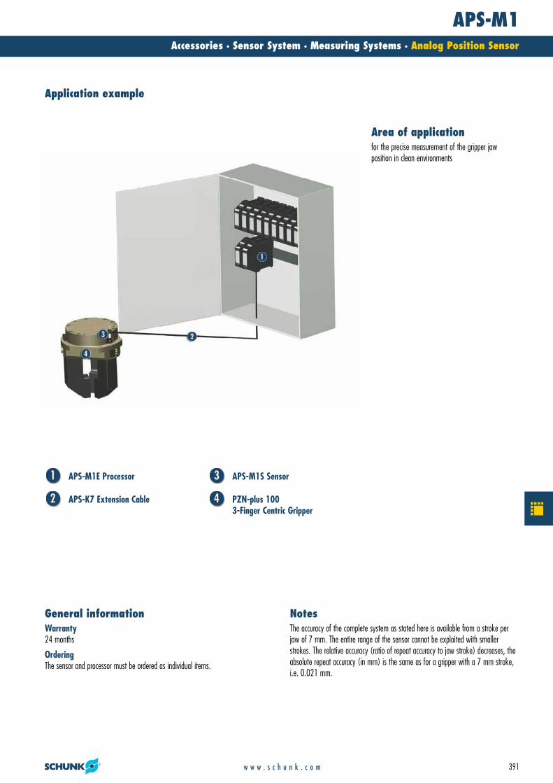
APS-M1E Processor
APS-K7 Extension Cable
APS-M1S Sensor
PZN-plus 100 3-Finger Centric Gripper
Warranty24 months
OrderingThe sensor and processor must be ordered as individual items.
General informationThe accuracy of the complete system as stated here is available from a stroke perjaw of 7 mm. The entire range of the sensor cannot be exploited with smaller strokes. The relative accuracy (ratio of repeat accuracy to jaw stroke) decreases, theabsolute repeat accuracy (in mm) is the same as for a gripper with a 7 mm stroke,i.e. 0.021 mm.
Notes
Application example
for the precise measurement of the gripper jaw position in clean environments
Area of application
21_Zub_Sensorik.qxd:Layout 1 29.04.2008 11:12 Uhr Seite 391

APS-M1Accessories · Sensor System · Measuring Systems · Analog Position Sensor
392 w w w . s c h u n k . c o m
Technical data
� When using an APS system, a mounting kit, APS sensor (APS-M1S) and processor (APS-M1E) arerequired for each gripper. The mounting kits can befound with the grippers. Mounting kits for other components/grippers are available on request. The sensor has a 3 m molded cable.
Wiring diagram
SW
rt
ws
bl
VCC
U+OSC
BR1BR2
OSC
U–
I+
I–
GND GND
VCC
V
A
�� ��
�$
�$ APS-M1S Sensor�� APS-M1E Electronic Processor�� Automation device, e.g. S7-300
Description APS-M1EID 0302064
Supply voltage DCNominal voltage [V] 24.0Min. voltage [V] 22.0Max. voltage [V] 26.0Nominal power current [A] 0.1IP class 20Min. ambient temperature [°C] 0.0Max. ambient temperature [°C] 60.0Repeat accuracy (sensor and processor) [%] 0.3Weight [kg] 0.16Housing material PAOutput signal 0..10 V DC | 4..20 mAFastening Top hat rail
Description APS-M1SID 0302062
Measuring stroke [mm] 2.0Measuring accuracy [mm] 0.004Nominal current input [A] 0.023Tightness 67Thermal drift of zero signal [%/10K] 0.1Thermal drift of amplification factor [%/10K] 0.2Min. ambient temperature [°C] 10.0Max. ambient temperature [°C] 60.0Weight [kg] 0.16Sensor material SteelCable sheath PUR
21_Zub_Sensorik.qxd:Layout 1 29.04.2008 11:12 Uhr Seite 392

APS-M1Accessories · Sensor System · Measuring Systems · Analog Position Sensor
393w w w . s c h u n k . c o m
�$ Position with retracted feeler rod�� Carbide ball 1/8“�� Initial stroke�� Range of measurement�� Free stroke
�$ Groove for mounting rail
APS processor APS sensor
As an option, an extension cable can be connected between the sensor and the processor.(The max. cable length between the sensor and the processor is 10 m, between the processor and its controller (SPC) max. 1 m.)Description ID LengthAPS-K2 0302066 2.0 mAPS-K7 0302068 7.0 m
APS-K extension cable
The suitable mounting kit is specified with the gripper.ID Description0302075 AS-APS-M1-64/10302076 AS-APS-M1-64/20302077 AS-APS-M1-80/10302078 AS-APS-M1-80/20302079 AS-APS-M1-100/10302080 AS-APS-M1-100/20302081 AS-APS-M1-125/10302082 AS-APS-M1-125/20302083 AS-APS-M1-160/1 and 240/20302084 AS-APS-M1-160/20302085 AS-APS-M1-200/1 and 380/20302086 AS-APS-M1-200/20302087 AS-APS-M1-240/10302088 AS-APS-M1-300/10302089 AS-APS-M1-300/20302090 AS-APS-M1-380/1
Mounting kits
21_Zub_Sensorik.qxd:Layout 1 29.04.2008 11:12 Uhr Seite 393

FPSAccessories · Sensor System · Measuring Systems · FPS Flexible Position Sensor
394 w w w . s c h u n k . c o m
A permanent magnet that moves with the base jaw permeates the FPS sensor withits magnetic field. The strength of this permeation changes depends on the distanceof the magnet from the sensor. This variable is recorded, evaluated and output by theFPS electronic processor.
Function descriptionSimplest operationwith just two buttons, or with the machine control system using free control lines
Simple start-upas the customer can set all positions during the teaching operation
Five digital outputsfor greater economy as compared to individual sensors
Small distance between two switching points, adjustable
Resistant to contaminationthrough non-ferromagnetic materials
Function and switching status displayvia LEDs on the electronic processor
Conforms to CEfor safety and long life during permanent operation
Digital technologyfor resistance to interference
Additional advantages of the FPS-F5 and F5 T- Measuring functionality- Communication and remote maintenance via RS-232 protocol- Position programming and readout of switching points- Monitoring of temperature and input voltage- Visualization via PC possible- Data logging- Calibration of system to gripper stroke- Intelligent access authorization- Adaptation to new product during the process
Your advantages and benefits
FPS Flexible Position Sensor
The FPS sensor system measures the position of gripper jaws. It then indicates in which of the five freely teachable zones the jaws currently are. Additionaly the jaw position can be readout via the „FPS Controller“ software.
21_Zub_Sensorik.qxd:Layout 1 29.04.2008 11:12 Uhr Seite 394

FPSAccessories · Sensor System · Measuring Systems · FPS Flexible Position Sensor
395w w w . s c h u n k . c o m
ResolutionThe resolution is the minimum stroke difference that is required in order to reliablydistinguish between two signals. Used in conjunction with most SCHUNK grippers, the FPS system achieves a resolution of 1 – 3 % of a jaw stroke. However, in somegrippers a resolution of only 10 % is achieved due to the nature of the design. More precise resolutions may be reached, however, with the use of special solutions.Please contact us regarding the resolution/accuracy of the FPS system.
Connector for the electronic processor (enclosed)12-pin circular connector (Binder type series 723, waterproof) suitable for connection cables with a diameter of 6 to 8 mm, recommended conductor cross-section 0.14 mm2 (max. 0.25 mm2)
Ambient conditionsUse within the range of strong magnetic fields is not recommended. Neither the FPSsensor nor the FPS magnet may come into contact with ferromagnetic dust, chips orother substances.
DisplayFive colored LEDs
Range of measurement5 to 30 mm with SCHUNK magnet (NdFeB magnet cut to size, dimensions 6 x 25 mm x L)with various lengths L depending on the part of the range of measurement
MaterialProcessor: Plastic PA 6Cable: PU, resistant to coolants/lubricants
Warranty24 months
General informationAll data were determined on the basis of SCHUNK attachments and specifications.Please consult us regarding use of the sensor with modules from other manufactu-rers.
Notes
Application example
Position sensing of gripper jaws up to a stroke ofapprox. 30 mm in environments that may be clean ordirty, but are free from steel chips.
Area of application
21_Zub_Sensorik.qxd:Layout 1 29.04.2008 11:12 Uhr Seite 395

FPS-SAccessories · Sensor System · Measuring Systems · FPS Flexible Position Sensor – Sensors
396 w w w . s c h u n k . c o m
Technical data
Either the FPS-S13 or the FPS-SM8 sensor is required,depending on the type of gripper. Each sensor is connected to its own FPS-F5/F5T processor.
FPS sensors
Description FPS-S 13 FPS-S M8ID 0301705 0301704
Cable diameter [mm] 3.5 3.5Cable length [cm] 30.0 30.0Connection of FPS on processor side M8 M8Weight [kg] 0,01 0,015Min. ambient temperature [°C] -25.0 -25.0Max. ambient temperature [°C] 70.0 70.0IP class (sensor) 65 65IP class (connector, plugged in) 65 65Min. bending radius (dynamic) [mm] 17.5 17.5Min. bending radius (static) [mm] 35.0 35.0
21_Zub_Sensorik.qxd:Layout 1 29.04.2008 11:12 Uhr Seite 396
FPS-SAccessories · Sensor System · Measuring Systems · FPS Flexible Position Sensor – Sensors
397w w w . s c h u n k . c o m
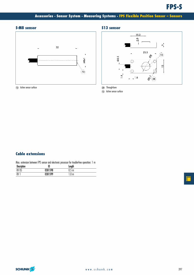
�" Through-bore�� Active sensor surface
�� Active sensor surface
S-M8 sensor S13 sensor
Max. extension between FPS sensor and electronic processor for trouble-free operation: 1 mDescription ID LengthKV 05 0301598 0.5 mKV 1 0301599 1.0 m
Cable extensions
21_Zub_Sensorik.qxd:Layout 1 29.04.2008 11:12 Uhr Seite 397

FPS-AAccessories · Sensor System · Measuring Systems · FPS Flexible Position Sensor – Electronic Processor
398 w w w . s c h u n k . c o m
Technical data
Measurement of the gripper stroke using sensors, comparison with target value, output of tolerance information „Within tolerance“, „Above tolerance“ or„Below tolerance“, plus „Open“ and „Closed“. Otherwise, like the FPS-F5.
FPS-F5T processorMeasurement of the gripper stroke using sensors,assignment to the positions/zones „Open“, „Intermediateposition 1,2,3“ or „Closed“, and output of a positionsignal. A maximum of four switching points/five zonesare freely programmable, RS-232 interface, remote main-tenance, measuring functionality, system calibration to themillimeter, temperature and voltage monitoring.
FPS-F5 processor
Description FPS-F5 FPS-F5 TID 0301805 0301807
Nominal voltage [V] 24.0 24.0Min. voltage (DC) [V] 10.0 10.0Max. voltage (DC) [V] 30.0 30.0Nominal current (DC) [A] 0.01 0.01Weight [kg] 0.06 0.06Min. ambient temperature [°C] -25.0 -25.0Max. ambient temperature [°C] 70.0 70.0IP class 65 65
21_Zub_Sensorik.qxd:Layout 1 29.04.2008 11:12 Uhr Seite 398

FPS-AAccessories · Sensor System · Measuring Systems · FPS Flexible Position Sensor – Electronic Processor
399w w w . s c h u n k . c o m
For the contact assignment of the connections on the SPC side, please refer to the user’smanual.
�$ SPC/PLC�� Machine panel (provided by customer)
Main views
StoreSelectOPENCBACLOSED
INPUT ØINPUT 1INPUT 2INPUT 3INPUT 4
+ VCC+ VCC
CLOSED
OPEN
ABC
Store
SelectFPS-S 13FPS-S M8
FPS-A5FPS-F5FPS-F5 T
��
�$
�$ Transparent plastic cover, over control and display panel�� Connector on sensor side�� Connector on control cabinet side
Wiring diagramfrom the electronic processor to the control cabinetDescription ID LengthKV 10 0301801 10.0 m
Cable extension (open wires)
21_Zub_Sensorik.qxd:Layout 1 29.04.2008 11:12 Uhr Seite 399

FPS SoftwareAccessories · Sensor System · Measuring Systems · FPS Flexible Position Sensor - Software
400 w w w . s c h u n k . c o m
Technical data
The free FPS Controller software allows the user to monitor the FPS processor via an RS-232 interface.As a result, the FPS system can be calibrated to strokemeasurement, the position can be read out and the FPS processor can be programmed. The FPS software also provides access to all auxiliary functions.
Software for FPS-F5/F5 T
Description SoftwareID (CD) 0301806Download www.schunk.comOperating system MS Windows
21_Zub_Sensorik.qxd:Layout 1 29.04.2008 11:12 Uhr Seite 400

FPS SoftwareAccessories · Sensor System · Measuring Systems · FPS Flexible Position Sensor - Software
401w w w . s c h u n k . c o m
Screenshot software
Gripper
FPS
Modemanalog / ISDN
PC with software“FPS-Controller”
Telephone socket Control center WWW / Internet Intranet
Telephone socket SPC
Modemanalog / ISDN
PC with software “FPS-Controller”
Possible connection methodsSet-up with laptop
21_Zub_Sensorik.qxd:Layout 1 29.04.2008 11:12 Uhr Seite 401

FMSAccessories · Sensor System · Measuring Systems · Force Measuring System
402 w w w . s c h u n k . c o m
The FMS intermediate jaws are screwed on between the gripper base jaw and thetop jaw, which comes in contact with the workpiece. Gripping forces on the top jawresult in a flow of force through the FMS intermediate jaw. Intelligently arrangedstrain gauges inside the intermediate jaw react to the resulting deformation. The FMS processor detects the change in the strain gauges and emits an analog signal indicating the force.
Function descriptionSimplest handlingvia a control line that is directly connected to an SPC
Easy-to-perform measurementof the actual, active gripping force
Result output via analog voltage value
Simple, linear relationshipbetween output voltage and gripping force
Simple zero balancingwith button or via control line
Integrated LCDfor visual monitoring
Easy assembly
Dirt-proof and waterproofalso for use in extreme ambient conditions
Your advantages and benefits
Force Measuring System
The FMS force measuring system is used for measuring the gripping forces during the gripping process. This opens up numerous new possibilities both during start-up and in the productionprocess.
21_Zub_Sensorik.qxd:Layout 1 29.04.2008 11:12 Uhr Seite 402

FMSAccessories · Sensor System · Measuring Systems · Force Measuring System
403w w w . s c h u n k . c o m
PGN-plus 100 AS 2-Finger Parallel Gripper
FMS-ZBA Intermediate Jaw with Sensor (active)
FMS-ZBP Intermediate Jaw without Sensor (passive)
Workpiece-specific Gripper Finger
Electronic Processor
For all PGN-plus and PZN-plus grippersand gripper with identical finger connection diagram available as a standard product,and for other grippers on request (remember to ask about the delivery time!)
Conforms to CEfor absolute safety and long life during permanent operation
Warranty24 months
General informationThe FMS force measuring system allows you to measure forces that act on the basejaw in the direction of the jaw movement. Up to three active (equipped with sensors)FMS-ZBA intermediate jaws are required for this purpose, depending on the application. The remaining base jaws are equipped with FMS-ZBP passive intermediate jaws (without sensors). Each FMS-ZBA active intermediate jaw requiresan FMS-A1 electronic processor for evaluation, and an FMS-AK connection cable forconnecting the electronic processor to an SPC or a control cabinet.
Notes
Application example
Gripping force controlBy sending control signals to the proportional valvethat supplies the gripper, the SPC can influence theautomatically measured gripping force.
Teaching robotsWhen gripping firmly fixed workpieces, the teaching ofrobots is simple and precise. Symmetrical gripping onlytakes place if the left- and right-hand gripper jawsapply the same force – thereby protecting the gripperand the robot.
Static grip force monitoringMonitoring the grip force as the jaws close prevents theworkpiece from being dropped when movement initiates.Overload protection by monitoring the max. permittedforce, which can be triggered e.g. by an inadvertent increase in pressure, by off-center gripping or the incorrectpositioning of the workpiece.Preventive maintenance by replacing grippers in goodtime when there is a decline in the gripping force. This avoids unexpected manufacturing down-times.
Dynamic grip force monitoringThe effect of acceleration forces on the gripper jaws can berecorded and the motion sequence modified if necessary.Component monitoring during highly dynamic movements.
Measuring and teaching processesDimensional checking of the gripped component on the basis of an inserted reference component. If the component to be measured differs by more than ± 0.05 mm from the reference component, teaching can take place. If the difference is smaller, the precise dimensions can be measured accurately even to within ± 0.002 mm.Gauging the weight of the component by measuring the force due to weight of the component on the gripperfingers.
Area of application
21_Zub_Sensorik.qxd:Layout 1 29.04.2008 11:12 Uhr Seite 403

FMS-AAccessories · Sensor System · Measuring Systems · Electronic Processor for Force Measuring System
404 w w w . s c h u n k . c o m
� The output voltage is linear to the forces occurring at the gripper fingers. The bandwidth of the output signal is not fully exploited by every active intermediate jaw. Zero balancing mustbe performed prior to measurement. The limit class A according to EN 61326 is complied with. The test to EN 61000-4-2, EN 61000-4-3, EN 61000-4-4 and EN 61000-4-6 was passed in conformity with EN 61326.
FMS Processor
Description FMS-A1 FMS-A2ID 0301810 0301811
Measuring accuracy [%] 3.0 3.0Output signal -5 VDC .. +5 VDC -5 VDC .. +5 VDCType of voltage DC DCNominal voltage [V] 24.0 24.0Min. voltage [V] 18.0 18.0Max. voltage [V] 30.0 30.0Nominal power current [A] 0.0045 0.0045IP class 67 67Weight [kg] 63.0 63.0
Each FMS-ZBA active intermediate jaw requires an electronic processor.
The FMS-A1 processor is required for intermediate jawsizes up to 125, the FMS-A2 processor from size 160.The electronic processor is used to prepare, display andforward the measurement results. It is equipped with ahousing connector and socket for connecting the forcemeasuring jaw and the connection cable.
21_Zub_Sensorik.qxd:Layout 1 29.04.2008 11:12 Uhr Seite 404

FMS-AAccessories · Sensor System · Measuring Systems · Electronic Processor for Force Measuring System
405w w w . s c h u n k . c o m
Main views
The FMS-AK connection cable is used for connecting the electronic processor to a controlcabinet or an SPC. A cable bushing is fitted on the side of the electronic processor, theother side is open.Description ID LengthFMS-AK5 0301821 5.0 mFMS-AK10 0301822 10.0 mFMS-AK20 0301823 20.0 m
FMS-AK connection cable
21_Zub_Sensorik.qxd:Layout 1 29.04.2008 11:12 Uhr Seite 405
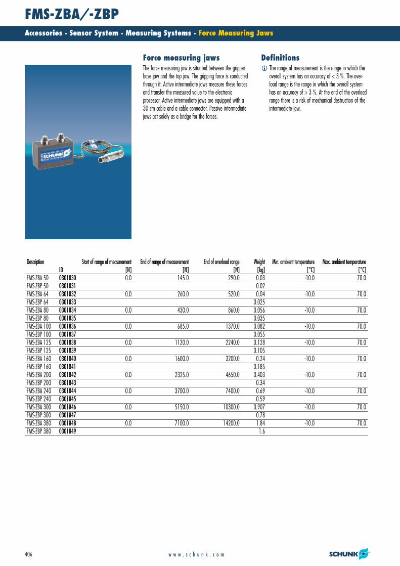
FMS-ZBA/-ZBPAccessories · Sensor System · Measuring Systems · Force Measuring Jaws
406 w w w . s c h u n k . c o m
DefinitionsForce measuring jaws
Description Start of range of measurement End of range of measurement End of overload range Weight Min. ambient temperature Max. ambient temperatureID [N] [N] [N] [kg] [°C] [°C]
FMS-ZBA 50 0301830 0.0 145.0 290.0 0.03 -10.0 70.0FMS-ZBP 50 0301831 0.02FMS-ZBA 64 0301832 0.0 260.0 520.0 0.04 -10.0 70.0FMS-ZBP 64 0301833 0.025FMS-ZBA 80 0301834 0.0 430.0 860.0 0.056 -10.0 70.0FMS-ZBP 80 0301835 0.035FMS-ZBA 100 0301836 0.0 685.0 1370.0 0.082 -10.0 70.0FMS-ZBP 100 0301837 0.055FMS-ZBA 125 0301838 0.0 1120.0 2240.0 0.128 -10.0 70.0FMS-ZBP 125 0301839 0.105FMS-ZBA 160 0301840 0.0 1600.0 3200.0 0.24 -10.0 70.0FMS-ZBP 160 0301841 0.185FMS-ZBA 200 0301842 0.0 2325.0 4650.0 0.403 -10.0 70.0FMS-ZBP 200 0301843 0.34FMS-ZBA 240 0301844 0.0 3700.0 7400.0 0.69 -10.0 70.0FMS-ZBP 240 0301845 0.59FMS-ZBA 300 0301846 0.0 5150.0 10300.0 0.907 -10.0 70.0FMS-ZBP 300 0301847 0.78FMS-ZBA 380 0301848 0.0 7100.0 14200.0 1.84 -10.0 70.0FMS-ZBP 380 0301849 1.6
� The range of measurement is the range in which theoverall system has an accuracy of < 3 %. The over-load range is the range in which the overall systemhas an accuracy of > 3 %. At the end of the overloadrange there is a risk of mechanical destruction of theintermediate jaw.
The force measuring jaw is situated between the gripperbase jaw and the top jaw. The gripping force is conductedthrough it. Active intermediate jaws measure these forcesand transfer the measured value to the electronic processor. Active intermediate jaws are equipped with a30 cm cable and a cable connector. Passive intermediatejaws act solely as a bridge for the forces.
21_Zub_Sensorik.qxd:Layout 1 29.04.2008 11:13 Uhr Seite 406

FMS-ZBA/-ZBPAccessories · Sensor System · Measuring Systems · Force Measuring Jaws
407w w w . s c h u n k . c o m
� Gripper connection� Finger connection�! Cable outlet
� Gripper connection� Finger connection
� Gripper connection� Finger connection
� Gripper connection� Finger connection�! Cable outlet
FMS-ZBA 50 FMS-ZBP 50
FMS-ZBA 64 FMS-ZBP 64
21_Zub_Sensorik.qxd:Layout 1 29.04.2008 11:13 Uhr Seite 407

FMS-ZBA/-ZBPAccessories · Sensor System · Measuring Systems · Force Measuring Jaws
408 w w w . s c h u n k . c o m
� Gripper connection� Finger connection�! Cable outlet
� Gripper connection� Finger connection
� Gripper connection� Attachment connection
� Gripper connection� Finger connection�! Cable outlet
FMS-ZBA 80 FMS-ZBP 80
FMS-ZBA 100 FMS-ZBP 100
21_Zub_Sensorik.qxd:Layout 1 29.04.2008 11:13 Uhr Seite 408

FMS-ZBA/-ZBPAccessories · Sensor System · Measuring Systems · Force Measuring Jaws
409w w w . s c h u n k . c o m
� Gripper connection� Finger connection�! Cable outlet
� Gripper connection� Finger connection
� Gripper connection� Finger connection
� Gripper connection� Finger connection�! Cable outlet
FMS-ZBA 125 FMS-ZBP 125
FMS-ZBA 160 FMS-ZBP 160
21_Zub_Sensorik.qxd:Layout 1 29.04.2008 11:13 Uhr Seite 409

FMS-ZBA/-ZBPAccessories · Sensor System · Measuring Systems · Force Measuring Jaws
410 w w w . s c h u n k . c o m
� Gripper connection� Finger connection�! Cable outlet
� Gripper connection� Finger connection
� Gripper connection� Finger connection
� Gripper connection� Finger connection�! Cable outlet
FMS-ZBA 200 FMS-ZBP 200
FMS-ZBA 240 FMS-ZBP 240
21_Zub_Sensorik.qxd:Layout 1 29.04.2008 11:13 Uhr Seite 410

FMS-ZBA/-ZBPAccessories · Sensor System · Measuring Systems · Force Measuring Jaws
411w w w . s c h u n k . c o m
� Gripper connection� Finger connection�! Cable outlet
� Gripper connection� Finger connection
� Gripper connection� Finger connection
� Gripper connection� Finger connection�! Cable outlet
FMS-ZBA 300 FMS-ZBP 300
FMS-ZBA 380 FMS-ZBP 380
21_Zub_Sensorik.qxd:Layout 1 29.04.2008 11:13 Uhr Seite 411
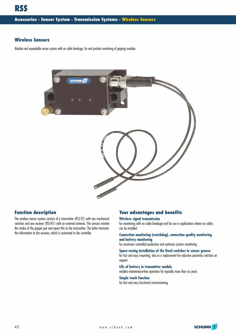
RSSAccessories · Sensor System · Transmission Systems · Wireless Sensors
412 w w w . s c h u n k . c o m
The wireless sensor system consists of a transmitter (RSS-T2) with two mechanicalswitches and one receiver (RSS-R1) with an external antenna. The sensors monitorthe stroke of the gripper jaw and report this to the transmitter. The latter transmitsthe information to the receiver, which is connected to the controller.
Function descriptionWireless signal transmissionfor monitoring with no cable breakage and for use in applications where no cablescan be installed
Connection monitoring (watchdog), connection quality monitoringand battery monitoringfor maximum controlled production and optimum system monitoring
Space-saving installation of the Reed switches in sensor groovefor fast and easy mounting, also as a replacement for inductive proximity switches onrequest
Life of battery in transmitter moduleenables maintenance-free operation for typically more than six years
Simple teach functionfor fast and easy functional commissioning
Your advantages and benefits
Wireless Sensors
Modular and expandable sensor system with no cable breakage, for end position monitoring of gripping modules.
21_Zub_Sensorik.qxd:Layout 1 29.04.2008 11:13 Uhr Seite 412

RSSAccessories · Sensor System · Transmission Systems · Wireless Sensors
413w w w . s c h u n k . c o m
Reed Switch RMS 22 in sensor groove of the 2-finger parallel gripper PGN-plus
Transmitter Module RSS-T2
Magnetic Base Antenna RSS-R-A
Receiver RSS-R1
Typical transmission rangesapprox. 10 meters in workshopsapprox. 30 meters in the open
Protection class according to DIN 40050IP 67 in connected condition for use in clean or dusty environments or in the eventof contact with water. Contact with other media (cooling lubricants, acidic or causticsubstances, etc.) frequently does not impair the function, but this cannot be guaranteed by SCHUNK.
Service life of transmitter battery:Min. 6 years at 2 transmissions/secondMin. 8 years at 1 transmission/secondUp to 10 years at lower cycles
Power supply, receiver24 V DC,500 mA output
Life of transmitter batteryMin. 6 years at 2 transmissions/secondMin. 8 years at 1 transmission/second
Warranty24 months
General informationSheet steel prevents propagation of radio waves. The radio energy transmitted by the RSS is a factor of 70,000 below that of DECTtelephones and a factor of 30,000 below that of GSM mobile phones.
Notes
Application example
The new wireless RSS sensor system can be usedanywhere where no cable feed is possible. For example in milling or grinding machines, machining centers, or in rotating or close applicationswhich are unsuitable for cable ducts. However, theRSS is also ideal for use in adverse ambient conditionsand explosive areas.
Area of application
21_Zub_Sensorik.qxd:Layout 1 29.04.2008 11:13 Uhr Seite 413

RSS-T2Accessories · Sensor System · Transmission Systems · Wireless Sensors
414 w w w . s c h u n k . c o m
Technical data
RSS-T2 transmitterThe RSS-T2 transmitter can transmit the signals from 2switches. We recommend the use of RMS 22 or RMS 80.Alternative switches can also be used. However, they mustnot require energy supply.
Transmitter moduleDescription RSS-T2
ID 0377710Transmitting frequency [MHz] 868.3Transmitter connection 2x M8Integrated power supply Lithium batteryTypical life of the battery [Years] 8Housing material PURLog Enocean standardTightness IP 67Min. ambient temperature [°C] 0Max. ambient temperature [°C] 50Weight [g] 0.16
21_Zub_Sensorik.qxd:Layout 1 29.04.2008 11:13 Uhr Seite 414
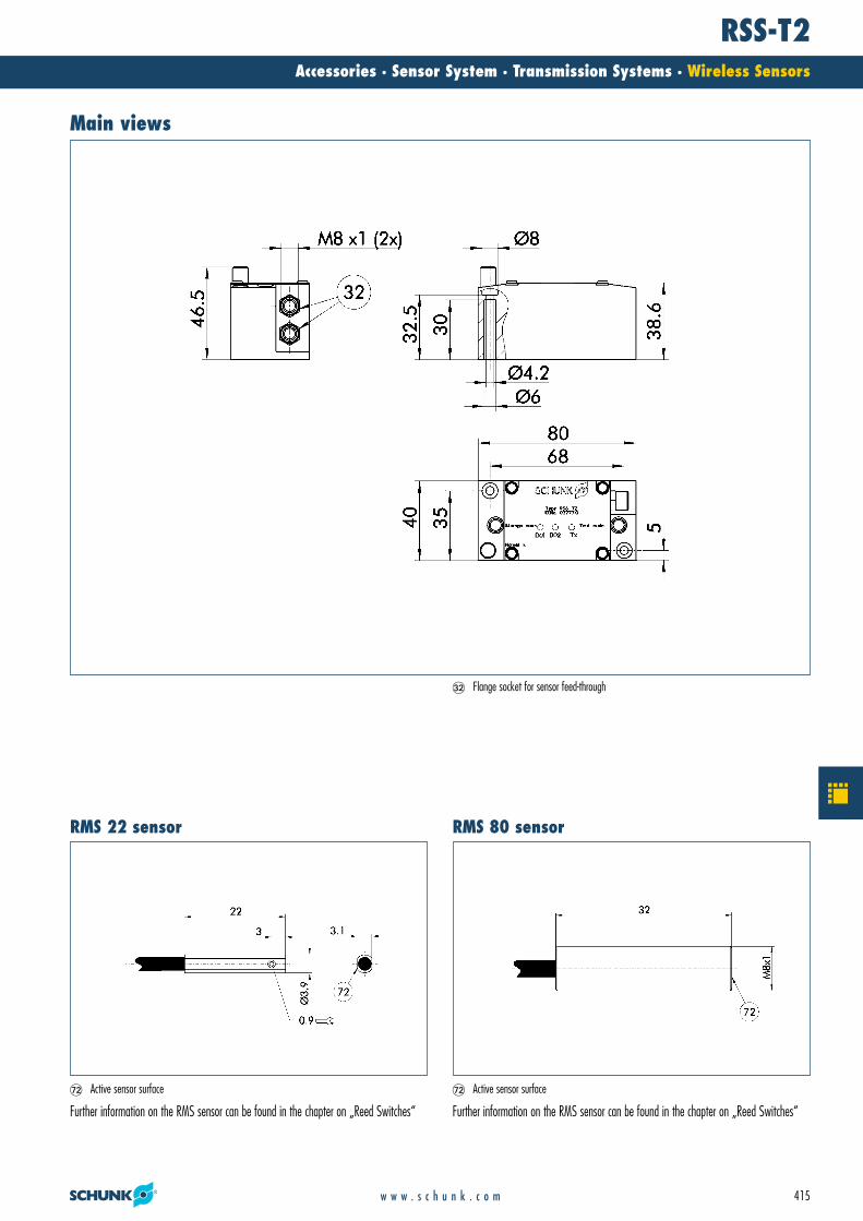
RSS-T2Accessories · Sensor System · Transmission Systems · Wireless Sensors
415w w w . s c h u n k . c o m
Further information on the RMS sensor can be found in the chapter on „Reed Switches“
�� Active sensor surface
Further information on the RMS sensor can be found in the chapter on „Reed Switches“
�� Active sensor surface
Main views
�� Flange socket for sensor feed-through
RMS 80 sensorRMS 22 sensor
21_Zub_Sensorik.qxd:Layout 1 29.04.2008 11:13 Uhr Seite 415

RSS-R1Accessories · Sensor System · Transmission Systems · Wireless Sensors
416 w w w . s c h u n k . c o m
Technical data
RSS-R1 receiverThe RSS-R1 receiver can receive the signals of the RSS-T2transmitter. One receiver and one antenna are needed foreach transmitter.
ReceiverDescription RSS-R1
ID 0377700Receiving frequency [MHz] 868.3Power supply DCNominal voltage [V] 24Min. voltage [V] 10Max. voltage [V] 30Max. current on contact per channel [mA] 500Housing material PURLog Enocean standardShort-circuit-proof YesTightness IP 20Fastening Top hat railMin. ambient temperature [°C] 0Max. ambient temperature [°C] 50
AntennaDescription RSS-R-A
ID 0377730Assembly Magnetic baseCable length [m] 2Connection to cable end SMA MiniUtilization Connection to receiver RSS-R1
21_Zub_Sensorik.qxd:Layout 1 29.04.2008 11:13 Uhr Seite 416

RSS-R1Accessories · Sensor System · Transmission Systems · Wireless Sensors
417w w w . s c h u n k . c o m
Main views
RSS-R-A antenna
21_Zub_Sensorik.qxd:Layout 1 29.04.2008 11:13 Uhr Seite 417

PA3Accessories · Sensor System · Other Systems · Fluidic Monitoring System
418 w w w . s c h u n k . c o m
The PA3 returns the information „open“, „gripped“ or „closed“ to the controller via asingle, additional pneumatic line. The pneumatic actuator only has to be modifiedwith two pneumatic connections for this purpose. The PA3 is started up via a pushbutton switch and a potentiometer. The unit is automatically taught during a set-upcycle.
Function descriptionPosition scan without electric sensorsfor diverse applications in new environments
An additional pneumatic line as an information hosetherefore only slight modification of the gripper necessary, also possible as retrofittingof existing components
Simple start-upvia button and potentiometer
self teach-in functionfor automatic teaching of the monitoring system during the set-up cycle
Your advantages and benefits
Fluidic Monitoring System
Pneumatic monitoring for three positions. For systems that can be monitored by means of conventional sensors.
21_Zub_Sensorik.qxd:Layout 1 29.04.2008 11:13 Uhr Seite 418

PA3Accessories · Sensor System · Other Systems · Fluidic Monitoring System
419w w w . s c h u n k . c o m
2-Finger Long-stroke Gripper PFH 30with special bores for the PA 3
Additional Information Source
PA 3-Electronic System
Power supply for electronics24 V DC
Warranty24 months
General information
Application example
The applications range from pneumatic gripper modules to pneumatic actuators, such as cylinders or rotary actuators. For example, when gripper modules must be monitored in places that are notaccessible by electric sensors or where electric sensorsare not allowed.
Area of application
21_Zub_Sensorik.qxd:Layout 1 29.04.2008 11:14 Uhr Seite 419

PA3Accessories · Sensor System · Other Systems · Fluidic Monitoring System
420 w w w . s c h u n k . c o m
Technical dataDescription PA3ID 0301780IP class 67Type of voltage DCNominal voltage [V] 24Min. voltage [V] 21.6Max. voltage [V] 26.4Nominal power current [mA] 30Maximum current [mA] 130Weight [kg] 1.13Hose connection [mm] 6Min. nominal pressure [bar] 3Max. pressure [bar] 10Permissible media Compressed airTypical switching time [s] 1
21_Zub_Sensorik.qxd:Layout 1 29.04.2008 11:14 Uhr Seite 420

PA3Accessories · Sensor System · Other Systems · Fluidic Monitoring System
421w w w . s c h u n k . c o m
Two additional bore holes in the piston chamber of the monitored components are connected with the AND valve. The resulting pressure signal is sent to the PA3.
�$ Input �� Output
Main views
AND valve
21_Zub_Sensorik.qxd:Layout 1 29.04.2008 11:14 Uhr Seite 421

ZHUAccessories · Mounting Elements · Centering Elements
422 w w w . s c h u n k . c o m
The centering sleeves are inserted coaxially to the screws.
Function descriptionSpace-savingfor small, compact grippers
Precisefor high repeat accuracy
Economicalfor low costs
Easy to installfor fast assembly
Your advantages and benefits
Centering sleeves
Centering sleeves are used for centering between two elements. With SCHUNK grippers, this frequently occurs between the mounting plate and gripper and between the gripper and gripper fingers.
22_Befestigungselemente.qxd:Layout 1 29.04.2008 11:31 Uhr Seite 422

ZHUAccessories · Mounting Elements · Centering Elements
423w w w . s c h u n k . c o m
MaterialSteel
Warranty24 months
General informationSCHUNK grippers include all necessary centering sleeves.
Notes
variable centering tasks for gripper and rotary modules, as well as linear modules.
Area of application
22_Befestigungselemente.qxd:Layout 1 29.04.2008 11:31 Uhr Seite 423
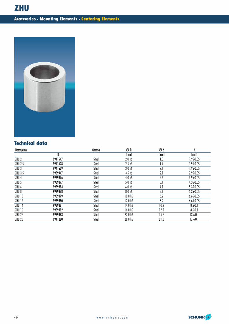
ZHUAccessories · Mounting Elements · Centering Elements
424 w w w . s c h u n k . c o m
Technical dataDescription Material Ø D Ø d H
ID [mm] [mm] [mm]ZHU 2 9941547 Steel 2.0 h6 1.3 1.95-0.05ZHU 2,5 9941628 Steel 2.5 h6 1.7 1.95-0.05ZHU 3 9941629 Steel 3.0 h6 2.1 1.95-0.05ZHU 3,5 9939947 Steel 3.5 h6 2.1 2.95-0.05ZHU 4 9939376 Steel 4.0 h6 2.6 3.95-0.05ZHU 5 9939377 Steel 5.0 h6 3.1 4.35-0.05ZHU 6 9939384 Steel 6.0 h6 4.1 5.35-0.05ZHU 8 9939378 Steel 8.0 h6 5.1 5.35-0.05ZHU 10 9939379 Steel 10.0 h6 6.2 6.65-0.05ZHU 12 9939380 Steel 12.0 h6 8.2 6.65-0.05ZHU 14 9939381 Steel 14.0 h6 10.2 8.6-0.1ZHU 16 9939382 Steel 16.0 h6 12.2 8.6-0.1ZHU 22 9939383 Steel 22.0 h6 16.2 13.6-0.1ZHU 28 9941220 Steel 28.0 h6 21.0 17.6-0.1
22_Befestigungselemente.qxd:Layout 1 29.04.2008 11:31 Uhr Seite 424

ZHUAccessories · Mounting Elements · Centering Elements
425w w w . s c h u n k . c o m
Main views
22_Befestigungselemente.qxd:Layout 1 29.04.2008 11:31 Uhr Seite 425

PAMAccessories · Mounting Elements · Connecting Elements for PowerCube
426 w w w . s c h u n k . c o m
The dimensions of the connecting elements are matched to the cube shape of thePowerCube modules. The accurately repeatable connection is made easily and quicklyby means of four hexagon socket screws.
Function descriptionStandard elementsfor high availability
Geometry designs „straight“, „conical“ and „angular“for maximum combinations
Suitable for all grippers, rotary units, drives and linear modules ofthe PowerCube series.
Your advantages and benefits
Connecting Elements for PowerCube
Standard elements and adapters for the accurately repeatable connections of PowerCube modules
22_Befestigungselemente.qxd:Layout 1 29.04.2008 11:31 Uhr Seite 426

PAMAccessories · Mounting Elements · Connecting Elements for PowerCube
427w w w . s c h u n k . c o m
Connecting element – straight PAM 100
Connecting element – conical PAM 110
Servo-electric 2-Finger Parallel Gripper PG 70
Servo-electric Rotary Actuator PR 70
Servo-electric Rotary Actuator PR 90
Warranty24 months
MaterialAluminum alloy, hard-anodized
General informationSpecial lengths are available on request.
Notes
Application example
For easy and accurately repeatable connection of allPowerCube modules
Area of application
22_Befestigungselemente.qxd:Layout 1 29.04.2008 11:31 Uhr Seite 427

PAM – StraightAccessories · Mounting Elements · Connecting Elements for PowerCube
428 w w w . s c h u n k . c o m
suitable for PowerCube-Modules of size 90Description IDPAM 102 0307802
suitable for PowerCube-Modules of size 90Description IDPAM 103 0307803
suitable for PowerCube-Modules of size 70Description IDPAM 101 0307801
suitable for PowerCube-Modules of size 70Description IDPAM 100 0307800
PAM 100 – straight PAM 101 – straight
PAM 102 – straight PAM 103 – straight
22_Befestigungselemente.qxd:Layout 1 29.04.2008 11:31 Uhr Seite 428

PAM – StraightAccessories · Mounting Elements · Connecting Elements for PowerCube
429w w w . s c h u n k . c o m
suitable for PowerCube-Modules of size 110Description IDPAM 105 0307805
suitable for PowerCube-Modules of size 110Description IDPAM 104 0307804
PAM 104 – straight PAM 105 – straight
22_Befestigungselemente.qxd:Layout 1 29.04.2008 11:31 Uhr Seite 429

PAM – AngledAccessories · Mounting Elements · Connecting Elements for PowerCube
430 w w w . s c h u n k . c o m
�" Through-bore
suitable for PowerCube-Modules of size 110Description IDPAM 122 0307822
�" Through-bore
suitable for PowerCube-Modules of size 90Description IDPAM 121 0307821
�" Through-bore
suitable for PowerCube-Modules of size 70Description IDPAM 120 0307820
PAM 120 – angled PAM 121 – angled
PAM 122 – angled
22_Befestigungselemente.qxd:Layout 1 29.04.2008 11:31 Uhr Seite 430

PAM – ConicalAccessories · Mounting Elements · Connecting Elements for PowerCube
431w w w . s c h u n k . c o m
suitable for PowerCube-Modules of size 90/110Description IDPAM 112 0307812
suitable for PowerCube-Modules of size 90/110Description IDPAM 113 0307813
suitable for PowerCube-Modules of size 70/90Description IDPAM 111 0307811
suitable for PowerCube-Modules of size 70/90Description IDPAM 110 0307810
PAM 110 – conical PAM 111 – conical
PAM 112 – conical PAM 113 – conical
22_Befestigungselemente.qxd:Layout 1 29.04.2008 11:31 Uhr Seite 431

PAM – Adapter PlatesAccessories · Mounting Elements · Connecting Elements for PowerCube
432 w w w . s c h u n k . c o m
suitable for PowerCube-Modules of size 110Description IDPAM 166 0307866
suitable for PowerCube-Modules of size 90Description IDPAM 165 0307865
suitable for PowerCube-Modules of size 70Description IDPAM 164 0307864
PAM 164 PAM 165
PAM 166
22_Befestigungselemente.qxd:Layout 1 29.04.2008 11:31 Uhr Seite 432

PAM – Adapter PlatesAccessories · Mounting Elements · For Special Modules
433w w w . s c h u n k . c o m
suitable for accurately repeatable connection of the force sensor FTCL-050 with the 2-finger parallel gripper PG 70Description IDPAM 161 0307861
suitable for accurately repeatable connection of the rotary pan-tilt actuator PW 70 with theforce sensor FTCL-050Description IDPAM 160 0307860
suitable for accurately repeatable connection of the 2-finger parallel gripper PG 70 with therotary pan-tilt actuator PW 70Description IDPAM 147 0307847
PAM 147 – PG to PW PAM 160 – PW to FTCL
PAM 161 – FTCL to PG
22_Befestigungselemente.qxd:Layout 1 29.04.2008 11:32 Uhr Seite 433

Valves and Screw ConnectionsAccessories · Pneumatic Modules · Valves and Screw Connections
434 w w w . s c h u n k . c o m
Suitablefor all SCHUNK gripper, rotary and linear modules, in addition to robot accessories
Flexible utilizationfor use on pneumatic hoses from various manufacturers
Fittings as plug-in connectionsfor fast hose attachment
SDV-P pressure maintenance valveprevents loss of pressure
Your advantages and benefits
Pressure Maintenance Valves and Fittings
for connection and mounting of pneumatic hoses
23_Ventile_Verschraubg.qxd:Layout 1 29.04.2008 12:40 Uhr Seite 434

Valves and Screw ConnectionsAccessories · Pneumatic Modules · Valves and Screw Connections
435w w w . s c h u n k . c o m
SDV-P Pressure Maintenance Valve
SWV Banjo Fitting
PGN-plus 2-Finger Parallel Gripperwith workpiece-specific gripper fingers
Warranty24 months
General information
Application example
for secure hose connections in automation solutions
Area of application
23_Ventile_Verschraubg.qxd:Layout 1 29.04.2008 12:40 Uhr Seite 435
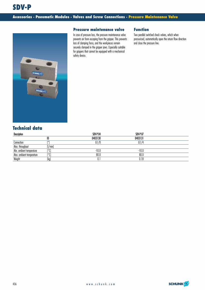
SDV-PAccessories · Pneumatic Modules · Valves and Screw Connections · Pressure Maintenance Valve
436 w w w . s c h u n k . c o m
Technical data
FunctionPressure maintenance valveIn case of pressure loss, the pressure maintenance valveprevents air from escaping from the gripper. This preventsloss of clamping force, and the workpieces remain securely clamped in the gripper jaws. Especially suitablefor grippers that cannot be equipped with a mechanicalsafety device.
Two parallel switched check valves, which whenpressurized, automatically open the return flow directionand close the pressure line.
Description SDV-P 04 SDV-P 07ID 0403130 0403131
Connection [”] G1/8 G1/4Max. throughput [l/min]Min. ambient temperature [°C] -10.0 -10.0Max. ambient temperature [°C] 80.0 80.0Weight [kg] 0.1 0.18
23_Ventile_Verschraubg.qxd:Layout 1 29.04.2008 12:40 Uhr Seite 436
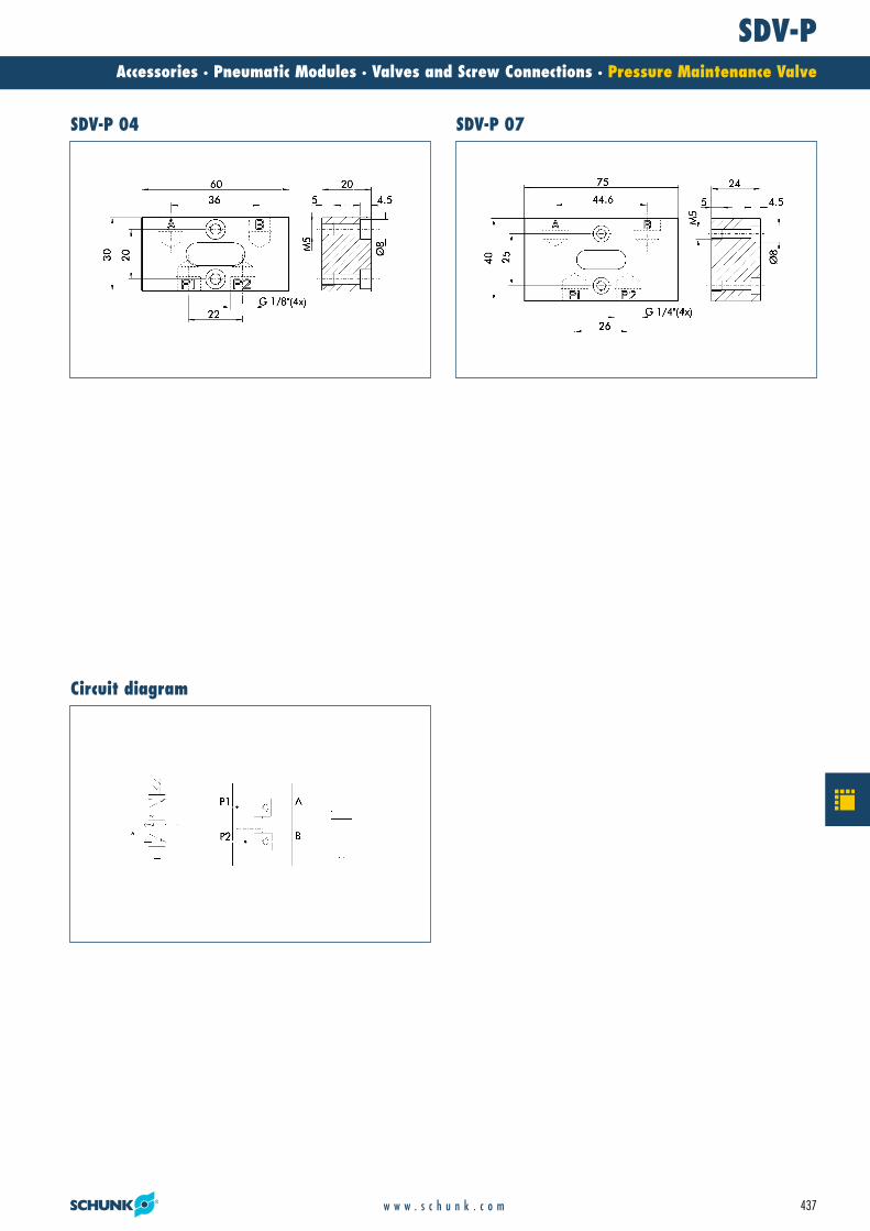
SDV-PAccessories · Pneumatic Modules · Valves and Screw Connections · Pressure Maintenance Valve
437w w w . s c h u n k . c o m
SDV-P 04 SDV-P 07
Circuit diagram
23_Ventile_Verschraubg.qxd:Layout 1 29.04.2008 12:40 Uhr Seite 437
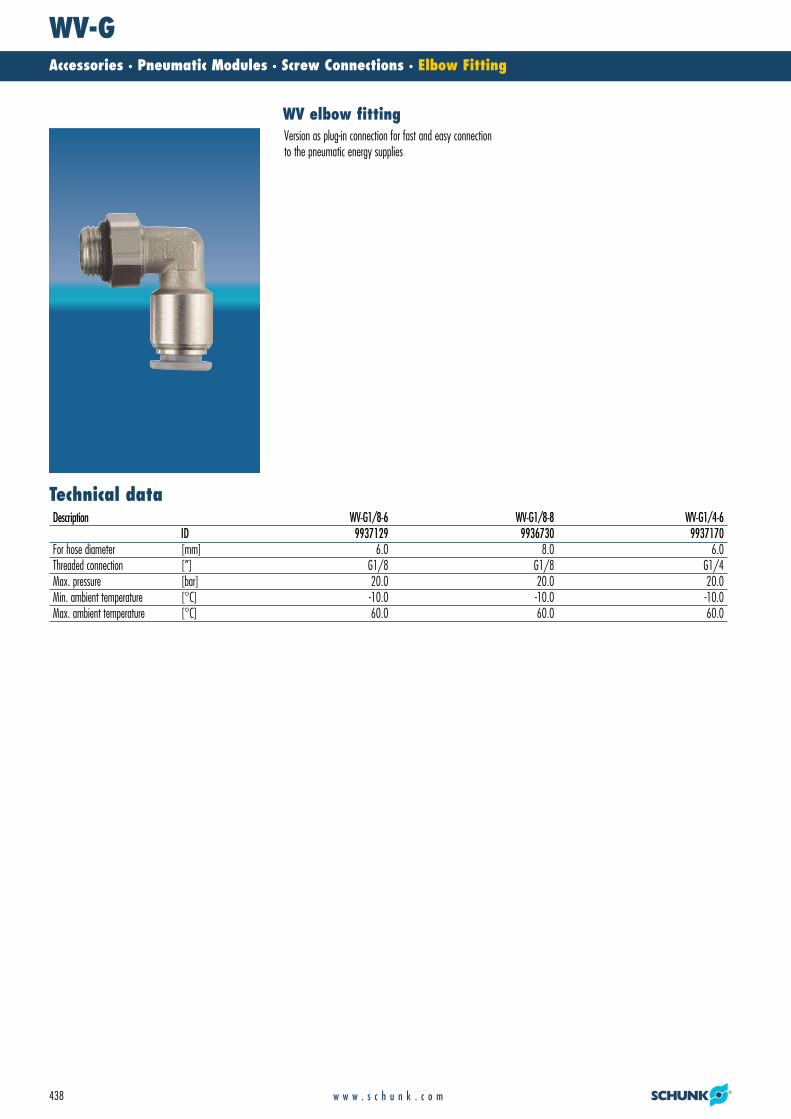
WV-GAccessories · Pneumatic Modules · Screw Connections · Elbow Fitting
438 w w w . s c h u n k . c o m
Technical data
WV elbow fittingVersion as plug-in connection for fast and easy connectionto the pneumatic energy supplies
Description WV-G1/8-6 WV-G1/8-8 WV-G1/4-6ID 9937129 9936730 9937170
For hose diameter [mm] 6.0 8.0 6.0Threaded connection [”] G1/8 G1/8 G1/4Max. pressure [bar] 20.0 20.0 20.0Min. ambient temperature [°C] -10.0 -10.0 -10.0Max. ambient temperature [°C] 60.0 60.0 60.0
23_Ventile_Verschraubg.qxd:Layout 1 29.04.2008 12:40 Uhr Seite 438
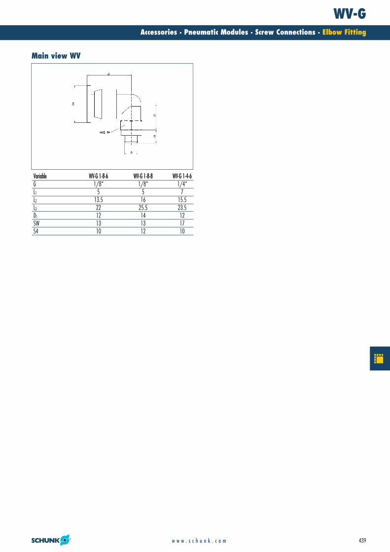
WV-GAccessories · Pneumatic Modules · Screw Connections · Elbow Fitting
439w w w . s c h u n k . c o m
Variable WV-G 1-8-6 WV-G 1-8-8 WV-G 1-4-6G 1/8“ 1/8“ 1/4“L1 5 5 7L2 13.5 16 15.5L3 22 25.5 23.5D1 12 14 12SW 13 13 17S4 10 12 10
Main view WV
23_Ventile_Verschraubg.qxd:Layout 1 29.04.2008 12:40 Uhr Seite 439

SWVAccessories · Pneumatic Modules · Valves and Screw Connections · Banjo Fitting
440 w w w . s c h u n k . c o m
SWV banjo fittingVersion as plug-in connection for fast and easy connectionto the pneumatic energy supplies
Description SWV-M3-4 SWV-M5-6 SWV-G4-6 SWV-G8-6 SWV-G4-8ID 9210505 9936171 9937128 9937152 9936728
For hose diameter [mm] 4.0 6.0 6.0 6.0 8.0Threaded connection [”] M 3 M 5 G1/4 G1/8 G1/4Max. pressure [bar] 20.0 20.0 20.0 20.0 20.0Min. ambient temperature [°C] -10.0 -10.0 -10.0 -10.0 -10.0Max. ambient temperature [°C] 60.0 60.0 60.0 60.0 60.0
23_Ventile_Verschraubg.qxd:Layout 1 29.04.2008 12:40 Uhr Seite 440

SWVAccessories · Pneumatic Modules · Valves and Screw Connections · Banjo Fitting
441w w w . s c h u n k . c o m
Variable SWV-M3-4G M3d3 1.1L1 2L2 2.5L3 7.3L4 7.3D1 3.4SW 5S4 5
Variable SWV-M5-6 SWV-G8-6 SWV-G4-6 SWV-G4-8G M5 G1/8“ G1/4“ G1/4“d3 2 5 7 7L1 4 6.5 8 8L2 6.2 8.25 8.4 15.3L3 18.5 22.5 24.5 25L4 15.8 20.5 21.6 21.6D1 10 12 12 13.5SW 8 14 17 17S4 10 15 19 19
Main view SWV Main view SWV-M3
23_Ventile_Verschraubg.qxd:Layout 1 29.04.2008 12:40 Uhr Seite 441
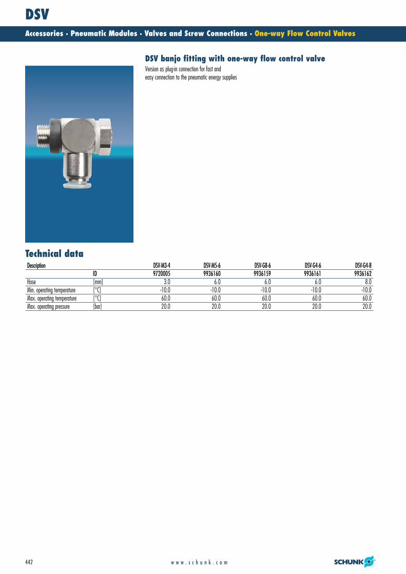
DSVAccessories · Pneumatic Modules · Valves and Screw Connections · One-way Flow Control Valves
442 w w w . s c h u n k . c o m
Technical data
DSV banjo fitting with one-way flow control valveVersion as plug-in connection for fast andeasy connection to the pneumatic energy supplies
Description DSV-M3-4 DSV-M5-6 DSV-G8-6 DSV-G4-6 DSV-G4-8ID 9720005 9936160 9936159 9936161 9936162
Hose [mm] 3.0 6.0 6.0 6.0 8.0Min. operating temperature [°C] -10.0 -10.0 -10.0 -10.0 -10.0Max. operating temperature [°C] 60.0 60.0 60.0 60.0 60.0Max. operating pressure [bar] 20.0 20.0 20.0 20.0 20.0
23_Ventile_Verschraubg.qxd:Layout 1 29.04.2008 12:40 Uhr Seite 442
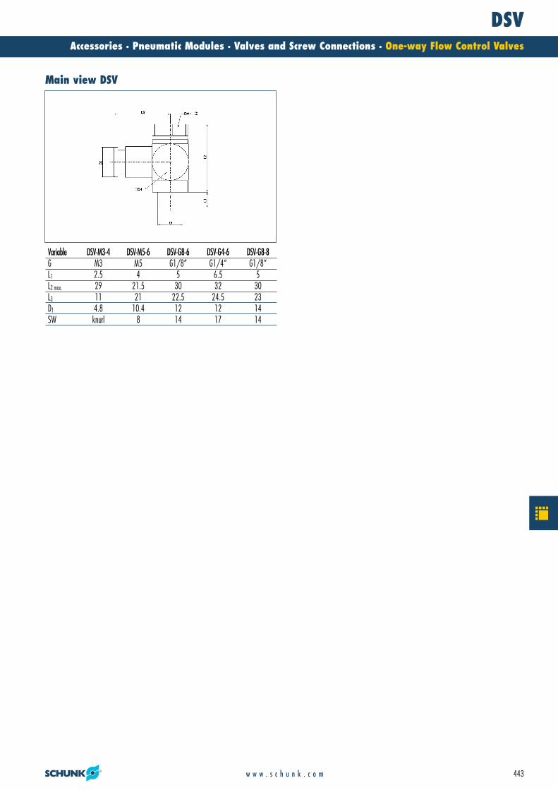
DSVAccessories · Pneumatic Modules · Valves and Screw Connections · One-way Flow Control Valves
443w w w . s c h u n k . c o m
Variable DSV-M3-4 DSV-M5-6 DSV-G8-6 DSV-G4-6 DSV-G8-8G M3 M5 G1/8“ G1/4“ G1/8“L1 2.5 4 5 6.5 5L2 max. 29 21.5 30 32 30L3 11 21 22.5 24.5 23D1 4.8 10.4 12 12 14SW knurl 8 14 17 14
Main view DSV
23_Ventile_Verschraubg.qxd:Layout 1 29.04.2008 12:40 Uhr Seite 443
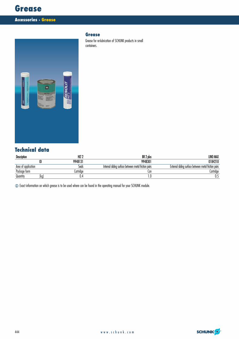
GreaseAccessories · Grease
444 w w w . s c h u n k . c o m
� Exact information on which grease is to be used where can be found in the operating manual for your SCHUNK module.
Technical data
GreaseGrease for re-lubrication of SCHUNK products in small containers.
Description HLT 2 BR 2 plus LINO MAXID 9948131 9948301 0184210
Area of application Seals Internal sliding surface between metal friction pairs External sliding surface between metal friction pairsPackage form Cartridge Can CartridgeQuantity [kg] 0.4 1.0 0.5
24_Schmierfette.qxd:Layout 1 29.04.2008 12:41 Uhr Seite 444

Notes
445w w w . s c h u n k . c o m
24_Schmierfette.qxd:Layout 1 29.04.2008 12:42 Uhr Seite 445

Cable/ConnectorAccessories · For Electric Modules · Cable/Connector
446 w w w . s c h u n k . c o m
High flexibility and tensile strengthfor a long service life
Excellent EMC propertiesthrough various shielding methods and the use of special materials
Special shell and insulation materialsfor high safety in the application
Your advantages and benefits
Cable and Connector
Connecting cable for the flexible connection of electric gripper modules and modules of the PowerCube series.
25_Kabel_Verbinder_elektr.qxd:Layout 1 29.04.2008 12:51 Uhr Seite 446

Cable/ConnectorAccessories · For Electric Modules · Cable/Connector
447w w w . s c h u n k . c o m
Hybrid Cable PAE 003 coiled
Hybrid Cable PAE 001 straight
Servo-electric Rotary Actuator PR 70
Servo-electric Linear Axis with ball-screw spindle drive PLS
PG 70 2-Finger Parallel Gripper
Warranty24 months
General information
Application example
for cabling of automation modules with each other andto external controllers
Area of application
25_Kabel_Verbinder_elektr.qxd:Layout 1 29.04.2008 12:51 Uhr Seite 447

Hybrid Cable PAEAccessories · For Electric Modules · Cable/Connector
448 w w w . s c h u n k . c o m
� The basic dimensions and wire size of the PAE 001 cable correspond to the cable versions PAE 002 and PAE 003.
Technical data
Hybrid cable for PowerCube modulesfor combined information and energy transmission.Coiled version with high restoring forces and extensionlength to a multiple of the closed block length.
Description PAE 001 PAE 002 PAE 003ID 9941120 0307753 0307754
Version straight coiled coiledBasic length [m] 0.3 0.46Length of path [m] 0.8 1.5Operating voltage, drive [V] 600 600 600Operating voltage, communication/logic [V] 450 450 450Cable diameter [mm] 8.5 8.5 8.5Minimum bending radius [mm] 42.5 42.5 42.5Optimum bending radius [mm] 85 85 85Number of conductors, drive 2 2 2Wire size, drive [mm2] 2.5 2.5 2.5Number of conductors, communication/logic 4 4 4Wire size, communication/logic [mm2] 0.15 0.15 0.15
25_Kabel_Verbinder_elektr.qxd:Layout 1 29.04.2008 12:51 Uhr Seite 448

Hybrid Cable PAEAccessories · For Electric Modules · Cable/Connector
449w w w . s c h u n k . c o m
The drawing shows the hybrid cable PAE in cross section.
�$ 2 wires with 2.5 mm2
�� 2 wires with 0.15 mm2
�� Wrapping
�� Filler�� Screen�� Outer covering
�� Cable length�$ Extended cable lengths
PAE 002/PAE 003 Wire size, PAE
25_Kabel_Verbinder_elektr.qxd:Layout 1 29.04.2008 12:52 Uhr Seite 449

Connecting Cable for MEGAccessories · For Electric Modules · Cable/Connector
450 w w w . s c h u n k . c o m
� The designations -W and -G stand for the design of the connector plug (right-angle and straight)
Technical data
Interconnecting cableInterconnecting cable for the electrical connection of the 2-finger parallel gripper MEG. The cables have straight orright-angle cable sockets and a stranded wire on the otherend.
Description MEG-EC-K5-W MEG-EC-K10-W MEG-EC-K5-G MEG-EC-K10-G MEG-IC-K5-W MEG-IC-K10-WID 0307765 0307766 0307767 0307768 0307760 0307761
Design of connector angle angle straight straight angle angleBasic length [m] 5.0 10.0 5.0 10.0 5.0 10.0Max. operating voltage [V] 300 300 300 300 300 300Cable diameter [mm] 4.8 4.8 4.8 4.8 4.8 4.8Number of conductors 14 14 14 14 14 14Wire cross section [mm2] 0.25 0.25 0.25 0.25 0.25 0.25
25_Kabel_Verbinder_elektr.qxd:Layout 1 29.04.2008 12:52 Uhr Seite 450
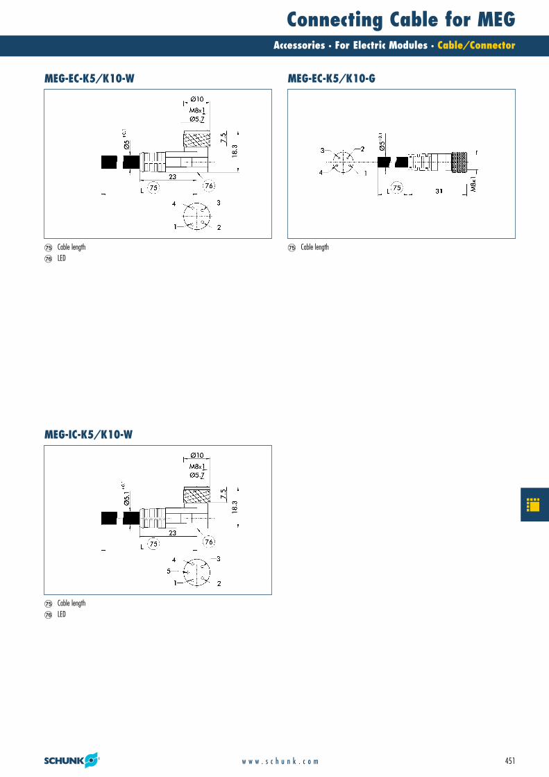
Connecting Cable for MEGAccessories · For Electric Modules · Cable/Connector
451w w w . s c h u n k . c o m
�� Cable length�� LED
�� Cable length�� Cable length�� LED
MEG-EC-K5/K10-W MEG-EC-K5/K10-G
MEG-IC-K5/K10-W
25_Kabel_Verbinder_elektr.qxd:Layout 1 29.04.2008 12:52 Uhr Seite 451

SLZAccessories · Tools · Hose Release Pliers
452 w w w . s c h u n k . c o m
The hose release pliers SLZ are used for fast, easy and finger-friendly removal ofpneumatic hoses from connectors. With the pliers, you can simultaneously press therelease ring and pull the hose from the connector – all with only one hand.
Function descriptionFinger-friendlyfor long, pleasant work periods
Flexible utilizationfor use on plug-in connections from various manufacturers
Color marking of the SLZ sizefor quickly finding the SLZ sizes in the toolbox for the correct hose diameter
Your advantages and benefits
Hose release pliers
26_SLZ.qxd:Layout 1 29.04.2008 12:55 Uhr Seite 452
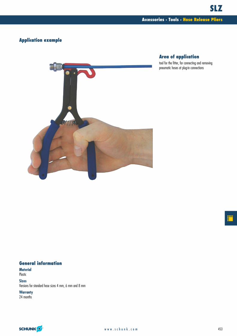
SLZAccessories · Tools · Hose Release Pliers
453w w w . s c h u n k . c o m
MaterialPlastic
SizesVersions for standard hose sizes 4 mm, 6 mm and 8 mm
Warranty24 months
General information
Application example
tool for the fitter, for connecting and removing pneumatic hoses at plug-in connections
Area of application
26_SLZ.qxd:Layout 1 29.04.2008 12:55 Uhr Seite 453
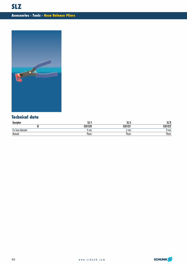
SLZAccessories · Tools · Hose Release Pliers
454 w w w . s c h u n k . c o m
Technical dataDescription SLZ 4 SLZ 6 SLZ 8
ID 0301020 0301021 0301022For hose diameter 4 mm 6 mm 8 mmMaterial Plastic Plastic Plastic
26_SLZ.qxd:Layout 1 29.04.2008 12:55 Uhr Seite 454

SLZAccessories · Tools · Hose Release Pliers
455w w w . s c h u n k . c o m
SLZ 4 SLZ 6
SLZ 8
26_SLZ.qxd:Layout 1 29.04.2008 12:55 Uhr Seite 455

456 w w w . s c h u n k . c o m
Notes
26_Schlussseiten_GB.qxd:Layout 1 29.04.2008 12:58 Uhr Seite 456

457w w w . s c h u n k . c o m
Notes
26_Schlussseiten_GB.qxd:Layout 1 29.04.2008 12:58 Uhr Seite 457

458 w w w . s c h u n k . c o m
Notes
26_Schlussseiten_GB.qxd:Layout 1 29.04.2008 12:58 Uhr Seite 458

459w w w . s c h u n k . c o m
Notes
26_Schlussseiten_GB.qxd:Layout 1 29.04.2008 12:58 Uhr Seite 459

460 w w w . s c h u n k . c o m
Notes
26_Schlussseiten_GB.qxd:Layout 1 29.04.2008 12:58 Uhr Seite 460

SCHUNK Service
We can provide you with professional, reliable and comprehensive support.
For you, SCHUNK Service means being on the safe side of effi ciency. For us,
it is an important part of our corporate philosophy. Our extensive range of
service – from initial advice to after sales service – convinces with absolute
reliability and technical knowledge.
Individual service – for better results Hotline to our inside technical consultants
weekdays from 7 a.m. to 6 p.m.
Project-orientated, on-site technical advice at your location by our
competent external consultants
Extensive stock of standard products with lightning fast delivery service
– world-wide!
Detailed information about clamping and automation technology
Training on innovations and SCHUNK-products – across the world in our
local subsidiaries
Online service – for a fast overviewAll information in digital form, clearly structured and up-to-date on our
website at www.schunk.com
List of contact persons
Online product search based on product designations
Product news and trends
Data sheets
Order forms for easy and convenient ordering
Free download area for pages from our product catalogs and technical
data, for software and calculation programs for your gripping and rotary
modules
Free 2-D/3-D CAD design models, provided in a wide range of different
CAD formats – for easy integration into your design!
461
✆✆
26_Schlussseiten_GB.qxd:Layout 1 29.04.2008 12:58 Uhr Seite 461

462 w w w . s c h u n k . c o m
Subsidiaries24
. 01.
08
ITALYSCHUNK Intec S.r.l.Via Caio Plinio 522072 Cermenate (CO)Tel. +39-031-770185Fax [email protected]
AUSTRIASCHUNK Intec GmbHHolzbauernstr. 204050 TraunTel. +43-7229-65770-0Fax [email protected]
BELGIUM, LUXEMBOURGSCHUNK Intec N.V./S. A.Bedrijvencentrum Regio AalstIndustrielaan 4, Zuid lll9320 Aalst -ErembodegemTel. +32-53-853504Fax [email protected]
SCHUNK GmbH & Co. KGShanghaiRepresentative Office777 Zhao Jia Bang RoadPine City Hotel, Room 923,Xuhui District,Shanghai 200032Tel. +86-21-64433177Fax [email protected]
CZECH REPUBLICSCHUNK Intec s.r.o.Ernsta Macha 1643 00 BrnoTel. +420-545 229 095Fax +420-545 220 [email protected]
DENMARKSCHUNK Intec A/SStorhaven 77100 VejleTel. +45-43601339Fax [email protected]
FRANCESCHUNK Intec SARLParc d‘Activités des Trois Noyers15, Avenue James de RothschildFerrières-en-Brie77614 Marne-la-Vallée Cedex 3Tel. +33-1-64 66 38 24Fax +33-1-64 66 38 [email protected]
GREAT BRITAIN, IRELANDSCHUNK Intec Ltd.Cromwell Business Centre10 Howard Way,Interchange ParkNewport Pagnell MK16 9QSTel. +44-1908-611127Fax [email protected]
HUNGARYSCHUNK Intec Kft.Széchenyi út. 70.3530 MiskolcTel. +36-46-50900-7Fax [email protected]
INDIASCHUNK India Branch Office# 80 B, YeswanthpurIndustrial Suburbs,Bangalore 560 022Tel. +91-80-41277361Fax [email protected]
NETHERLANDSSCHUNK Intec B.V.Speldenmakerstraat 3d5232 BH ‘s-HertogenboschTel. +31-73-6441779Fax [email protected]
SOUTH KOREASCHUNK Intec Korea Ltd.# 907 JoongangInduspia 2 Bldg.,144-5 Sangdaewon-dong,Jungwon-gu, Seongnam-si,Kyunggi-do, 462-722Tel. +82-31-7376141Fax [email protected]
SPAINSCHUNK Intec S.L.Foneria, 2708304 Mataró (Barcelona)Tel. +34-937 556 020Fax +34-937 908 [email protected]
SWEDENSCHUNK Intec ABMorabergsvägen 28152 42 SödertäljeTel. +46-8 554 421 00Fax +46-8 554 421 [email protected]
SWITZERLAND,LIECHTENSTEINSCHUNK Intec AGSoodring 198134 Adliswil 2Tel. +41-44-7102171Fax [email protected]
USASCHUNK Intec Inc.211 Kitty Hawk DriveMorrisville, NC 27560Tel. +1-919-572-2705Fax [email protected]
POLANDSCHUNK Intec Sp.z o.o.ul. Sloneczna 116 AStara Iwiczna05-500 PiasecznoTel. +48-22-7262500Fax [email protected]
PORTUGALSales RepresentativeVictor MarquesTel. +34-937-556 020Fax +34-937-908 692Mobil +351-963-786 [email protected]
CHINASCHUNK Precision Machinery(Hangzhou) Co., Ltd.6, 24th Street, HEDAHangzhou 310018Tel. +86-571-8672-1000Fax [email protected]
GERMANYHEAD OFFICESCHUNK GmbH & Co. KGSpann- und GreiftechnikBahnhofstr. 106 -13474348 Lauffen/NeckarTel. +49-7133-103-0Fax [email protected]
CANADASCHUNK Intec Corp.190 Britannia Road East,Units 23-24Mississauga, ON L4Z 1W6Tel. +1-905-712-2200Fax [email protected]
MEXICO, VENEZUELASCHUNK Intec S.A. de C.V.Av. Luis Vega y Monroy # 332Fracc. Plazas de SolSantiago de Querétaro, Qro. 76099Tel. +52-442-223-6525Fax [email protected]
SLOVAKIASCHUNK Intec s.r.o.Mostná 62949 01 NitraTel. +421-37-3260610Fax [email protected]
TURKEYSCHUNK IntecBaglama Sistemleri veOtomasyon San. ve Tic. Ltd. Sti.Küçükyalı Is MerkeziGirne MahallesiIrmak Sokak, A Blok, No: 934852 Maltepe, IstanbulTel. +90-216-366-2111Fax [email protected]
26_Schlussseiten_GB.qxd:Layout 1 29.04.2008 12:58 Uhr Seite 462

463w w w . s c h u n k . c o m
✆
Distribution Partners
BRAZILProdromus Comercio de EquipamentosPara Automacão LTDAAv.Gen.Cavacanti deAlbuquerque, 123CEP 05638-010 São Paulo, SPTel. +55-11-37410897Fax [email protected]
Sanches Blanes S.A.Estrada de Sapopemba, KM 41CEP 09436-000 Ribeirao Pires, SPTel. +55-11-48242742 Fax +55-11-48279009 [email protected]
CROATIABIBUS Zagreb d.o.o.Anina 9110000 ZagrebTel. +385-13818006Fax [email protected]
FINLANDNurminen Tools OyVanha Vantontie 221100 NaantaliTel. +358-2-4389668Fax [email protected]
HUNGARYIMI International KFT. Norgren DivisionNagykörösi UT 991205 BudapestTel. +36-1-421-4031Fax [email protected]
AUSTRALIAROMHELD AUSTRALIA PTY. LTD.Unit 30 / 115 Woodpark RoadSmithfield NSW 2164Tel. +61-2-97211799Fax +61-2-97211766sales@romheldaustralia.com.auwww.romheldaustralia.com.au
JAPANBIG Daishowa Seiki Co., Ltd.Aihara Koyamada Juei 510,Goshiki-cho, Sumoto-shi,Hyogo, 656-1317, JapanTel. +81-799-320115Fax [email protected]
Kitagawa Iron Works Co. Ltd.77-1 MotomachiFuchu-shi, Hiroshima 726-8610Tel. +81-847-454560Fax [email protected]
Takano Bearing Co. Ltd.45-28 3-Chome SannoOhta-Ku Tokyo 143-0023Tel. +81-33-7743731Fax [email protected]
Hakamada Yasuri Seisakusho & Corp.5-10, ShinsakaeKariya 4480843 Tel. +81-566-210443Fax [email protected]
NORWAYSivilingeniør Sture Hedløv a.s Kjellstad Næringssenter3400 LierTel. +47-32-846588Fax [email protected]
SINGAPOREBalluff Asia Pte Ltd.BLK 1004,Toa Payoh Industrial ParkLorong 8, # 03-1489Singapore 319076Tel. +65-62524384Fax [email protected]
APS - Automation & ProductionSystems PTE. Ltd.46, East Coast Road# 06-03, EastgateSingapore 428766Tel. +65-64695810Fax [email protected]
Eureka Tools Pte Ltd194 Pandan Loop# 04-10 Pantech Industrial ComplexSingapore 128383Tel. +65-68745781Fax [email protected]
ESTONIADV-Tools OÜPeterburi tee 34/411415, TallinnMobile Phone +372-56-655954Fax [email protected]
THAILANDZion Co., ltd.1213/54 Ladphrao 94 (Panjamitr)Khwaeng / Khet WangthonglangBangkok 10310Tel. +66-2-559-3379/81Fax [email protected]
SLOVAKIABIBUS SK, s.r.o.Priemyselna 494901 NitraTel. +421-37-7412525Fax [email protected]
SLOVENIAMB-Naklo Trgovsko Podjetje D.O.O.Toma Zupana 1604202 NakloTel. +386-42-771700Fax [email protected]
SOUTH AFRICAAGM Maschinenbau (Pty) Ltd.P.O. Box 4246Germiston South, 1411Tel. +27-11-825-4246Fax [email protected]
Traconsa (Pty) Ltd. (EDMS) BPKP.O. Box 1471, Kempton Park 1620Tel. +27-11-394-2810Fax [email protected]
SOUTH KOREAMAPAL HiTECO Co., Ltd.1NA-502, Shiwha Ind. Complex 1254-10, Jungwang-dong,Shihung-cityKyunggi -do, 429-450Tel. +82-31-3190-860Fax [email protected]
TAIWANYonchin Enterprises, Inc.P.O. Box 26-135F, No. 100,Hsing Der Rd.,San Chung City 241, Hsin TaipeiTel. +886-2-2278-9330Fax [email protected]
Danyao Trading Co., Ltd.7 F, No. 19, Chung-Cheng Rd.Hsin Chuang City, 242Taipei County, TaiwanTel. +886-2-22768200Fax +886-2-22767573E-Mail: [email protected]
POLANDBIBUS MENOS Sp. z.o.o.UL. Tadeusza Wendy 7/981-341 GdyniaTel. +48-586609596Fax [email protected]
CZECHREPUBLIC
BIBUS s.r.o.Vídenská 12563927 BrnoTel. +420-5 47 12 53 26Fax +420-5 47 12 53 [email protected]
INDONESIAPT. Metaltech IndonesiaJl, Gatot Subroto Km. 8Tangerang 15136Tel. +62-21-55657435Fax [email protected]
GREECEGeorg Gousoulis Co. O.E.27, Riga Fereou Str.14452 Metamorfosi-AthensTel. +30-210-2846771/2Fax [email protected]
RUSSIAHaltec Ltd.27/31 Radischeva str.432071 UlyanovskTel. +7-8422-414717Fax [email protected]
ARGENTINARuben Costantini S.A.Ingeniero Luis Angel Huergo 1320 Parque Industrial2400 San Francisco-CórdobaTel. +54-3564-421033Fax +54-3564-428877alejandro.costantini@costantini-sa.comwww.costantini-sa.com
ROMANIAS.C. INMAACRO S.R.L.Industrial Machines and Accessories RomaniaBronzului 7, BL 509A, AP 8500169 BrasovTel. +40-268-423450Fax [email protected]
UKRAINEDE&TC «Contact» JSC5, Kabardinskaya str.49006, Dnipropetrovs’kTel. +38-0562-317614Fax [email protected] www.kontakt.dp.ua
IRANIran Int. Procurement of Industries Co. (I.I.P.I.)No. 10, First alleyGolshan St., Khoramshahr Ave.Tehran, 1554814771Tel. +98-21-8875 0965Fax +98-21-8875 [email protected]
ISRAELIlan and Gavish Automation Service Ltd.26, Shenkar St.Qiryat-Arie 49513P.O. Box 10118,Petach-Tikva 49001Tel. +972-3-9221824Fax [email protected]
M. K. SalesArimon 41 St.Mosave Gealya 76885Tel. +972-528-283391Fax [email protected]
Chuck Jaws
Automation
Toolholding Systems
Stationary Workholding
Lathe Chucks
ICELANDFormula 1 ehfBreidamörk 25P.O. Box 1 61810 HveragerdiTel. +354-5172200Fax [email protected]
VENEZUELAAlpin de Venezuela, C.A.Calle G - Residencias RositaLocal No. 6-P.B.-El ParaisoSector El Pinar -Caracas 1020Tel. +58-212-4510484Fax [email protected]
MALAYSIASK-TECAutomation & Engineering Sdn. BhdNo. 56-A, Jalan PU7/347100 Puchong,Selangor Darul EhsanTel. +603-8060-8771Fax [email protected]
✆
26_Schlussseiten_GB.qxd:Layout 1 29.04.2008 12:58 Uhr Seite 463

Plants
Lauffen/Neckar, Sales and Production Toolholding and Workholding
SCHUNK GmbH & Co. KG · Spann- und GreiftechnikBahnhofstr. 106 - 134 · 74348 Lauffen/NeckarTel. +49-7133-103-0 · Fax [email protected] · www.schunk.com
Germany
Mengen, Sales and Production Lathe Chucks
H.-D. SCHUNK GmbH & Co. Spanntechnik KGLothringer Str. 23 · 88512 MengenTel. +49-7572-7614-0 · Fax [email protected] · www.schunk.com
Morrisville/North Carolina, USA
SCHUNK Intec Inc.211 Kitty Hawk Drive · Morrisville, NC 27560Tel. +1-919-572-2705 · Fax [email protected] · www.us.schunk.com
Hangzhou, China
SCHUNK Precision Machinery (Hangzhou) Co., Ltd.6, 24th Street, HEDA · Hangzhou 310018Tel. +86-571-8672-1000 · Fax [email protected] · www.cn.schunk.com
Brackenheim-Hausen, Sales and Production Automation
SCHUNK GmbH & Co. KG · Spann- und GreiftechnikRobert-Bosch-Str. 12 · 74336 Brackenheim-HausenHotline Technical Sales +49-7133-103-2503 Hotline Technical Support +49-7133-103-2696Fax [email protected] · www.schunk.com
International
CopyrightAll text drawings and product illustrations are subject to copyright and are the property of SCHUNK GmbH & Co. KGTechnical ChangesThe data and illustrations in this catalogue are not binding and only provide an approximate description. We reserve the right to make changes to the product delivered compared with the data and illustrations in this catalogue, e.g. in respect of technical data, design, fi ttings, material and external appearance.
464 w w w . s c h u n k . c o m
26_Schlussseiten_GB.qxd:Layout 1 29.04.2008 12:58 Uhr Seite 464

465w w w . s c h u n k . c o m
Fax OrderCopy, complete, fax to +49-7133-103-2189
SCHUNK GmbH & Co. KGSpann- und GreiftechnikBahnhofstr. 106 - 134 D-74348 Lauffen/NeckarHotline Technical Sales +49-7133-103-2503Hotline Technical Support +49-7133-103-2696Fax [email protected]
Company
Name
Department
Street
ZIP City
Tel. Fax
Order
Date Signature
The general terms of sales and conditions of SCHUNK GmbH & Co. KG apply
Pos. Quantity Type ID
1
2
3
4
5
6
7
8
9
10✆✆
26_Schlussseiten_GB.qxd:Layout 1 29.04.2008 12:58 Uhr Seite 465

Catalog OrderCopy, complete, fax to +49-7133-103-2779
HighlightsNew Products
SCHUNK GmbH & Co. KGSpann- und GreiftechnikBahnhofstr. 106 - 134 D-74348 Lauffen/NeckarTel. +49-7133-103-0Fax [email protected]
Company
Name
Department
Street
ZIP City
Tel. Fax
Toolholding and Workholding
Toolholding Systems Stationary Workholding Lathe Chucks Chuck Jaws
Complete program Toolholding and Workholding
Automation Complete program Automation
Gripping Modules Rotary Modules Linear Modules Robot Accessories
HighlightsNew Products
Modular Robotics System GEMOTECModular Assembly Technology
System GEMOTECLinear Modules with direct drives
Product Overview
System GEMOTECProduct Overview
Hydraulic Expansion Technology Special Solutions
Industry Solutions Food Industry
Industry Solutions Packaging Industry
Product Overview
Machine Vision
CD-ROM Automation
26_Schlussseiten_GB.qxd:Layout 1 29.04.2008 12:58 Uhr Seite 466

sCHuNK takes the initiative. For you.
SCHUNK AUTOMATION anticipates technological trends and customer needs, and turns them into unique pro-ducts, solutions and services.
As the most innovative market leader for more than 20 years we stand for state-of-the-art technology. Continuously we are setting trends for the entire Automation industry.
Take advantage of our comprehensive range of gripping modules, rotary and swivel units, linear modules, robot accessories and industry specific applications.
Discover in us a partner whose consistency and innova- tion will permanently strengthen your market position. In every industry. Worldwide.
GrIppING MODUleS rOTAry MODUleS lINeAr MODUleS rObOT ACCeSSOrIeS MODUlAr ASSeMbly MACHINe VISION AUTOMATION
The desire to automate handling applications is our
inspiration for solutions that help you succeed.
Heinz-Dieter Schunk
Umschlag_Drehmodule_GB.indd 2 22.04.2008 10:55:54 Uhr

R o t a R y M o d u l e s
a u t o M a t I o NRo
ta
Ry
M
od
ul
es
w w w . s c h u n k . c o m 9948
231
- 6M
- 04
/200
8
Umschlag_Drehmodule_GB.indd 1 22.04.2008 10:55:53 Uhr