Embed Size (px)
Citation preview
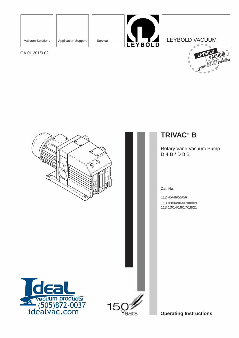
TRIVAC® B
Rotary Vane Vacuum PumpD 4 B / D 8 B
Cat. No.
112 45/46/55/56
113 03/04/06/07/08/09113 13/14/16/17/18/21
Operating Instructions
GA 01.201/9.02
Vacuum Solutions Application Support Service LEYBOLD VACUUM
GA 01.201/9.02 - 06/01
Contents
2
ContentsPage
IMPORTANT SAFETY CONSIDERATIONS . . . 4
1 Description . . . . . . . . . . . . . . . . . . . . . . . . . . 61.1 Function . . . . . . . . . . . . . . . . . . . . . . . . . . . . . 61.2 Supplied equipment . . . . . . . . . . . . . . . . . . . . . 81.3 Accessories . . . . . . . . . . . . . . . . . . . . . . . . . . . 91.4 Spare parts . . . . . . . . . . . . . . . . . . . . . . . . . . . 91.5 Transportation . . . . . . . . . . . . . . . . . . . . . . . . . 91.6 Technical data . . . . . . . . . . . . . . . . . . . . . . . . 101.6.1 Motor related data . . . . . . . . . . . . . . . . . . . . . 11
2 Operation . . . . . . . . . . . . . . . . . . . . . . . . . . . 122.1 Installation . . . . . . . . . . . . . . . . . . . . . . . . . . . 122.2 Connection to the system . . . . . . . . . . . . . . . 122.3 Electrical connection . . . . . . . . . . . . . . . . . . . 132.3.1 Pump with single-phase AC motor . . . . . . . . . 132.3.2 Pump with three-phase AC motor . . . . . . . . . 132.4 Start-up . . . . . . . . . . . . . . . . . . . . . . . . . . . . . 142.4.1 Areas of application . . . . . . . . . . . . . . . . . . . . 142.5 Operation . . . . . . . . . . . . . . . . . . . . . . . . . . . 152.5.1 Pumping of non-condensable gases . . . . . . . 152.5.2 Pumping of condensable gases and vapours . 152.5.3 Operating temperature . . . . . . . . . . . . . . . . . . 152.6 Switching off/shutdown . . . . . . . . . . . . . . . . . 162.6.1 Shutdown through monitoring components . . . 162.6.2 Failure of the control system or the
mains power . . . . . . . . . . . . . . . . . . . . . . . . 16
3 Maintenance . . . . . . . . . . . . . . . . . . . . . . . . 173.1 Checking the oil level . . . . . . . . . . . . . . . . . . . 173.1.1 Checking the condition of N 62 or HE-200 Oil 173.2 Oil change . . . . . . . . . . . . . . . . . . . . . . . . . . . 183.3 Cleaning the dirt trap . . . . . . . . . . . . . . . . . . . 183.4 Removing and fitting the internal demister . . . 193.5 Disassembly and reassembly of the
electric motor . . . . . . . . . . . . . . . . . . . . . . . 203.6 Replacing the outer shaft seal . . . . . . . . . . . . 213.7 Removing and remounting the pump module . 223.7.1 Removing the pump module . . . . . . . . . . . . . 223.7.2 Remounting the pump module . . . . . . . . . . . . 223.8 Leybold service . . . . . . . . . . . . . . . . . . . . . . . 233.8.1 Waste disposal of used pump materials . . . . . 233.9 Storing the pump . . . . . . . . . . . . . . . . . . . . . . 233.10 Troubleshooting . . . . . . . . . . . . . . . . . . . . . . . 243.11 Maintenance plan . . . . . . . . . . . . . . . . . . . . . 25
EEC Declaration of Conformity . . . . . . . . . . 26EEC Manufacturer’s Declaration . . . . . . . . . 27
We reserve the right to modify the design and thespecified data. The illustrations are not binding.
Note
3GA 01.201/9.02 - 06/01
We strongly recommend that you readthese Operating Instructions with care so asto ensure optimum operation of the pumpright from the start.
Indicates procedures that must be strictlyobserved to prevent hazards to persons.
Indicates procedures that must strictly beobserved to prevent damage to, ordestruction of the pump.
FiguresThe references to diagrams, e.g. (1/2) consist of the Fig.No. and the Item No. in that order.
Leybold-Service
If a pump is returned to LEYBOLD, indicate whether thepump is free of substances damaging to health orwhether it is contaminated.
If it is contaminated also indicate the nature of thehazard. LEYBOLD must return any pumps without a„Declaration of Contamination“ to the sender’s address.
Disposal of Waste Oil
Owners of waste oil are entirely self-responsible forproper disposal of this waste.
Waste oil from vacuum pumps must not be mixed withother substances or materials.
Waste oil from vacuum pumps (Leybold oils which arebased on mineral oils) which are subject to normal wearand which are contaminated due to the influence ofoxygen in the air, high temperatures or mechanical wearmust be disposed of through the locally available wasteoil disposal system.
Waste oil from vacuum pumps which is contaminatedwith other substances must be marked and stored insuch a way that the type of contamination is apparent.This waste must be disposed of as special waste.
European, national and regional regulations concerningwaste disposal need to be observed. Waste must only betransported and disposed of by an approved wastedisposal vendor.
Warning
Caution
4 GA 01.201/9.02 - 06/01
IMPORTANT SAFETY CONSIDERATIONS The Leybold TRIVAC B vacuum pump is designed for safe and efficient operation when used properly and inaccordance with this manual. It is the responsibility of the user to carefully read and strictly observe all safetyprecautions described in this section and throughout the manual. This product must be operated and maintained bytrained personnel only. Consult local, state, and national agencies regarding specific requirements and regulations.Address any further safety, operation and/or maintenance questions to your nearest Leybold Vacuum office.
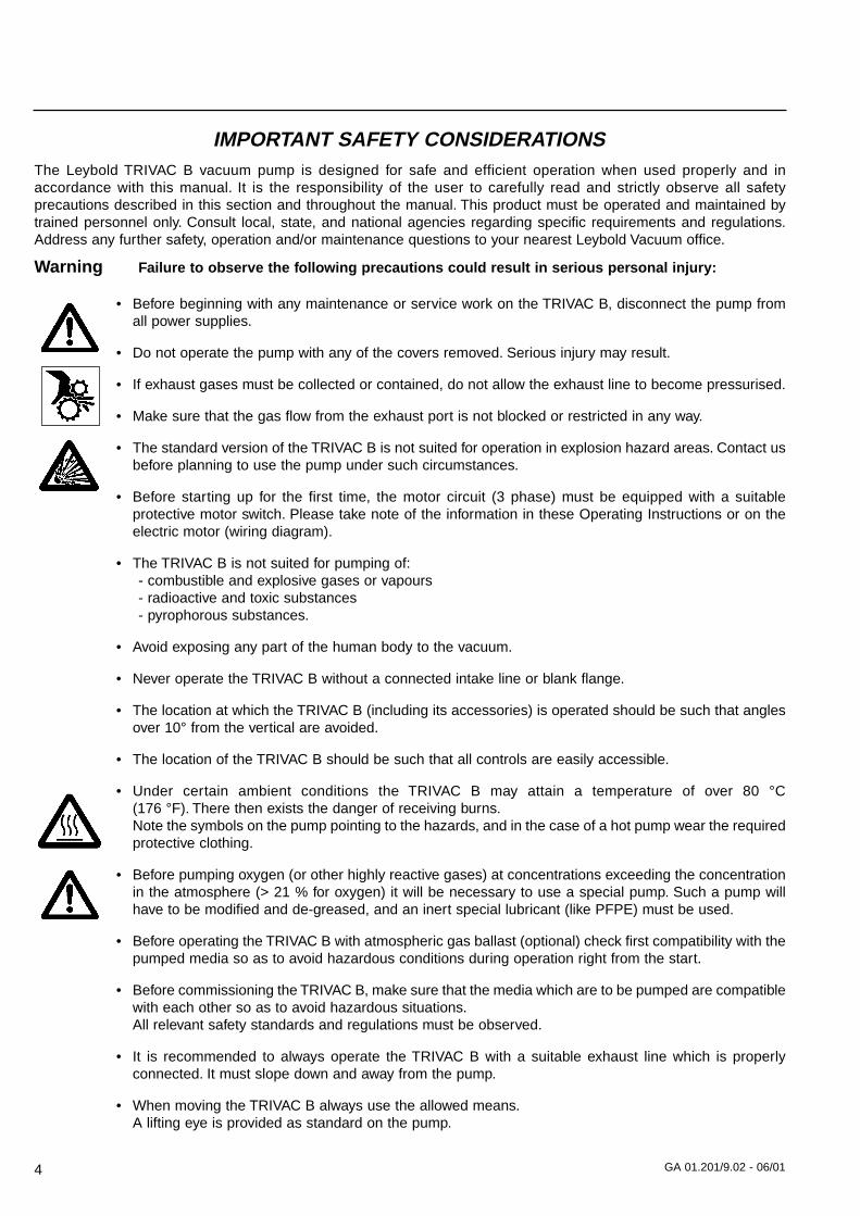
Warning Failure to observe the following precautions could result in serious personal injury:
• Before beginning with any maintenance or service work on the TRIVAC B, disconnect the pump fromall power supplies.
• Do not operate the pump with any of the covers removed. Serious injury may result.
• If exhaust gases must be collected or contained, do not allow the exhaust line to become pressurised.
• Make sure that the gas flow from the exhaust port is not blocked or restricted in any way.
• The standard version of the TRIVAC B is not suited for operation in explosion hazard areas. Contact usbefore planning to use the pump under such circumstances.
• Before starting up for the first time, the motor circuit (3 phase) must be equipped with a suitable protective motor switch. Please take note of the information in these Operating Instructions or on theelectric motor (wiring diagram).
• The TRIVAC B is not suited for pumping of:- combustible and explosive gases or vapours- radioactive and toxic substances- pyrophorous substances.
• Avoid exposing any part of the human body to the vacuum.
• Never operate the TRIVAC B without a connected intake line or blank flange.
• The location at which the TRIVAC B (including its accessories) is operated should be such that anglesover 10° from the vertical are avoided.
• The location of the TRIVAC B should be such that all controls are easily accessible.
• Under certain ambient conditions the TRIVAC B may attain a temperature of over 80 °C (176 °F). There then exists the danger of receiving burns.Note the symbols on the pump pointing to the hazards, and in the case of a hot pump wear the requiredprotective clothing.
• Before pumping oxygen (or other highly reactive gases) at concentrations exceeding the concentrationin the atmosphere (> 21 % for oxygen) it will be necessary to use a special pump. Such a pump willhave to be modified and de-greased, and an inert special lubricant (like PFPE) must be used.
• Before operating the TRIVAC B with atmospheric gas ballast (optional) check first compatibility with thepumped media so as to avoid hazardous conditions during operation right from the start.
• Before commissioning the TRIVAC B, make sure that the media which are to be pumped are compatiblewith each other so as to avoid hazardous situations.All relevant safety standards and regulations must be observed.
• It is recommended to always operate the TRIVAC B with a suitable exhaust line which is properlyconnected. It must slope down and away from the pump.
• When moving the TRIVAC B always use the allowed means.A lifting eye is provided as standard on the pump.
5GA 01.201/9.02 - 06/01
Failure to observe the following precautions could result in damage to the pump:
• Do not allow the ingestion of small objects (screws, nuts, washers, pieces of wire, etc.)through the inlet port. Always use the screen which is supplied with every pump.
• Do not use the pump for applications that produce abrasive or adhesive powders or condensable vapours that can leave adhesive or high viscosity deposits. Please contact Leybold Salesor Service to select a suitable separator. Also pease contact Leybold Sales or Service when planningto pump vapours other than water vapour.
• This pump is suited for pumping water vapour within the specified water vapour tolerance limits.
• Avoid vapours that can condense into liquids upon compression inside the pump, if these substancesexceed the vapour tolerance of the pump (> 25 mbar for water vapour).
• Before pumping vapours, the TRIVAC B should have attained its operating temperature, and the gasballast should be set to position I (position 0 = closed, position I = max. water vapour tolerance, 25mbar).The pump will have attained its operating temperature about 30 minutes after starting the pump. Duringthis time the pump should be separated from the process, by a valve in the intake line, for example.
• In the case of wet processes we recommend the installation of liquid separators upstream anddownstream of the pump as well as the use of the gas ballast.
• The exhaust line should be laid so that it slopes down and away from the pump so as to preventcondensate from backstreaming into the pump. For this preferably use the flange on the side of themotor.
• The entry of particles and fluids must be avoided under all circumstances.
• Reactive or aggressive substances in the pump chamber may impair the operating oil or modify it.In addition, such substances may be incompatible with the materials of the pump (Viton, grey cast iron,aluminium, steel, resins, glass etc.).
• Corrosion, deposits and cracking of oil within the pump are not allowed.
This information will help the operator to obtain the best performance from the equipment:
• Normal amounts of humidity within the range of the pump’s vapour tolerance will not significantly affect pump performance when the gas ballast is active. Preferably use the exhaust flange located on the sideof the motor.
Caution:In the case of custom pumps (with a Cat. No. deviating from the Cat No. stated in the EC Declaration of Conformity) please note the information provided on a separate sheet.
Caution
Note
Description
6 GA 01.201/9.02 - 06/01
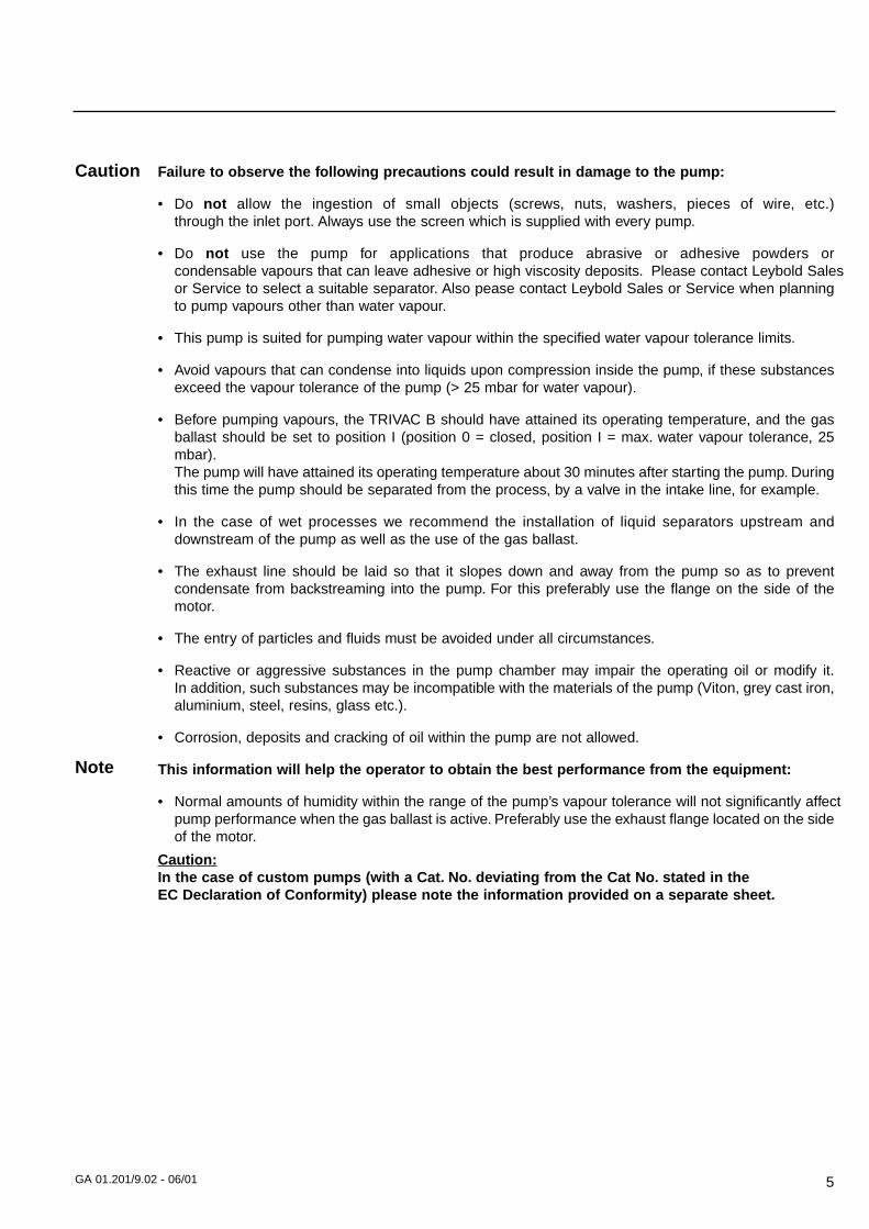
1 2 3
1 DescriptionTRIVAC-B pumps are oil-sealed rotary vane pumps. TheTRIVAC D 4 B and D 8 B are dual-stage pumps. Thenumber in the type designation (4 or 8) indicates thepumping speed in m3 · h-1.
TRIVAC-B pumps can pump gases and vapours andevacuate vessels or vacuum systems in the fine vacuumrange. Those of standard design are not suitable forpumping greater than atmospheric concentrations ofoxygen, hazardous gases, or extremely aggressive orcorrosive media.
The drive motor of the TRIVAC-B is directly flanged tothe pump at the coupling housing. The pump and motorshafts are directly connected by a flexible coupling. Thebearing points of the pump module are force lubricatedsliding bearings. All controls as well as the oil-level glassand the nameplate are arranged on the front. Allconnections are to be found at the sides of the pump.The oil-level glass is provided with prisms for betterobservation of the oil level.
The pump module consists of assembly parts which arepin-fitted so as to allow easy disassembly andreassembly. The pump module can be easily removedwithout special tools.
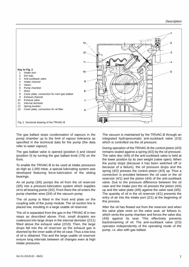
1.1 FunctionThe rotor (2/7), mounted eccentrically in the pumphousing (2/6) (pump chamber), has two radially slidingvanes (2/5) which divide the pump chamber into severalcompartments. The volume of each compartmentchanges periodically with the rotation of the rotor.
As a result, gas is sucked in at the intake port (2/1). Thegas passes through the dirt trap sieve (2/2), flows pastthe open anti-suckback valve (2/3) and then enters thepump chamber. In the pump chamber, the gas is passedon and compressed, after the inlet aperture is closed bythe vane.
The oil injected into the pump chamber is used forsealing and lubricating. The slap noise of the oil in thepump which usually occurs when attaining the ultimatepressure is prevented by admitting a very small amountof air into the pump chamber.
The compressed gas in the pump chamber is ejectedthrough the exhaust valve (2/10). The oil entrained in thegas is coarsely trapped in the internal demister (2/11);there the oil is also freed of mechanical impurities. Thegas leaves the TRIVAC-B through the exhaust port.
During compression, a controlled amount of air – the so-called gas ballast – can be allowed to enter the pumpchamber by opening the gas ballast valve (position I).
Key to Fig. 11 Oil filter OF 4-252 Exhaust filter AF 4-83 Condensate trap AK 4-8
Fig. 1 TRIVAC-B with accessories
Description
7GA 01.201/9.02 - 06/01
The gas ballast stops condensation of vapours in thepump chamber up to the limit of vapour tolerance asspecified in the technical data for the pump (the datarefer to water vapour).
The gas ballast valve is opened (position I) and closed(position 0) by turning the gas ballast knob (7/5) on thefront.
To enable the TRIVAC-B to be used at intake pressuresas high as 1,000 mbar, a special lubricating system wasdeveloped featuring force-lubrication of the slidingbearings.
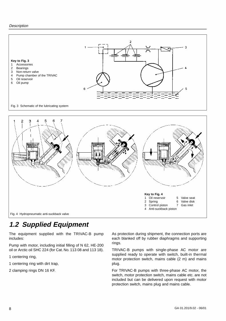
An oil pump (3/6) pumps the oil from the oil reservoir(3/5) into a pressure-lubrication system which suppliesoil to all bearing points (3/2). From there the oil enters thepump chamber area (3/4) of the vacuum pump.
The oil pump is fitted in the front end plate on thecoupling side of the pump module. The oil suction line isplaced low, resulting in a large usable oil reservoir.
The oil is separated from the gas in the TRIVAC-B in twosteps as described above. First, small droplets arecoalesced into large drops in the internal demister (2/11)fitted above the exhaust valve (2/10). Then, the largedrops fall into the oil reservoir as the exhaust gas isdiverted by the inner walls of the oil case.Thus a low lossof oil is obtained. This and the large usable oil reservoirensure long intervals between oil changes even at highintake pressures.
The vacuum is maintained by the TRIVAC-B through anintegrated hydropneumatic anti-suckback valve (2/3)which is controlled via the oil pressure.
During operation of the TRIVAC-B the control piston (4/3)remains sealed against a spring (4/2) by the oil pressure.The valve disc (4/6) of the anti-suckback valve is held atthe lower position by its own weight (valve open). Whenthe pump stops (because it has been switched off orbecause of a failure), the oil pressure drops and thespring (4/2) presses the control piston (4/3) up. Thus aconnection is provided between the oil case or the oilreservoir (4/1) and the piston (4/4) of the anti-suckbackvalve. Due to the pressure difference between the oilcase and the intake port the oil presses the piston (4/4)up and the valve plate (4/6) against the valve seat (4/5).The quantity of oil in the oil reservoir (4/1) prevents theentry of air into the intake port (2/1) at the beginning ofthis process.
After the oil has flowed out from the reservoir and whenthe valve plate rests on the valve seat, air follows in,which vents the pump chamber and forces the valve disc(4/6) against its seat. This effectively preventsbackstreaming of oil. The anti-suckback valve (2/3)operates independently of the operating mode of thepump, i.e. also with gas ballast.
Fig. 2 Sectional drawing of the TRIVAC-B
Key to Fig. 21 Intake port2 Dirt trap3 Anti-suckback valve4 Intake channel5 Vanes6 Pump chamber7 Rotor8 Cover plate, connection for inert gas ballast9 Exhaust channel
10 Exhaust valve11 Internal demister12 Spring buckles13 Cover plate, connection for oil filter
Description
8 GA 01.201/9.02 - 06/01
1.2 Supplied EquipmentThe equipment supplied with the TRIVAC-B pumpincludes:
Pump with motor, including initial filling of N 62, HE-200oil or Arctic oil SHC 224 (for Cat. No. 113 08 and 113 18).
1 centering ring,
1 centering ring with dirt trap,
2 clamping rings DN 16 KF.
As protection during shipment, the connection ports areeach blanked off by rubber diaphragms and supportingrings.
TRIVAC-B pumps with single-phase AC motor aresupplied ready to operate with switch, built-in thermalmotor protection switch, mains cable (2 m) and mainsplug.
For TRIVAC-B pumps with three-phase AC motor, theswitch, motor protection switch, mains cable etc. are notincluded but can be delivered upon request with motorprotection switch, mains plug and mains cable.
Fig. 3 Schematic of the lubricating system
Fig. 4 Hydropneumatic anti-suckback valve
Key to Fig. 31 Accessories2 Bearings3 Non-return valve4 Pump chamber of the TRIVAC5 Oil reservoir6 Oil pump
Key to Fig. 41 Oil reservoir 5 Valve seat2 Spring 6 Valve disk3 Control piston 7 Gas inlet4 Anti-suckback piston
Description
9GA 01.201/9.02 - 06/01
1.3 AccessoriesCat. No. / Ref. No.
Condensate trap AK 4-8, DN 16 KF . . . . . . . . . .188 06Exhaust filter AF 4-8, DN 16 KF . . . . . . . . . . . . .189 06
Drain tap for condensate trap, exhaust filter, oil drain of the pump, vacuum-tight . . . . . . . . . . . . . . . . . . . . . . . . . . .190 90oil tight . . . . . . . . . . . . . . . . . . . . . . . . . . . . . . .190 90
Exhaust filter with lubricant return AR 4-8, DN 16 KF . . . . . . . . . . . . . . . . . . . . . . .189 20
Dust filter FS 2-4 . . . . . . . . . . . . . . . . . . . . . . . .186 05
Fine vacuum adsorption trap FA 2-4(with zeolite) . . . . . . . . . . . . . . . . . . . . . . . . . . .187 05Adsorption trap(with aluminium oxide) . . . . . . . . . . . . . . . . . . . .854 14(with cryo insert) . . . . . . . . . . . . . . . . . . . . . . . .854 17Cold trap TK 4-8 . . . . . . . . . . . . . . . . . . . . . . . .188 20Oil filter OF 4-25 . . . . . . . . . . . . . . . . . . . . . . . .101 91Chemical filter CF 4-25 . . . . . . . . . . . . . . . . . . .101 96
Adapter for gas ballast port M 16 x 1.5 – DN 16 KF . . . . . . . . . . . . . . . . . . .168 40M 16 x 1.5 – 3/8 inch NPT . . . . . . . . . . . . .99 175 011
Oil N 62 1l 177 015l 177 0220 l 177 03
Arctic oil SHC 224 1l 200 28 181
(Order from LH Cologne, Germany)
Oil HE-200 1 qt 98 198 00612 qt case 98 198 0491 gal 98 198 0075 gal 98 198 008
(Order from LHVP, Export Pa., USA)
The oil grades N 62 and HE-200 are interchangeable.Special oils upon request.
Only use the kind of oil specified byLeybold. Alternative types of oil arespecified upon request.
1.4 Spare PartsSet of gaskets 197 20
Pump module, complete D 4 B 200 10 989D 8 B 200 10 991
Module-gasket 200 10 730*)
Oil case gasket 200 10 733*)
Internal demister D 4 B 390 26 010*)D 8 B 390 26 011*)
*) included in gasket set
1.5 Transportation
• Pumps which are filled with operatingagents must only be moved whilestanding upright. Otherwise oil mayescape. Avoid any other orientationsduring transport.
• Check the pump for the presence of anyoil leaks, since there exists the dangerthat someone may slip on spilt oil.
• When lifting the pump you must makeuse of the crane eyes provided on thepump for this purpose; also use therecommended type of lifting device.
Caution
Caution
Warning
Description
10 GA 01.201/9.02 - 06/01
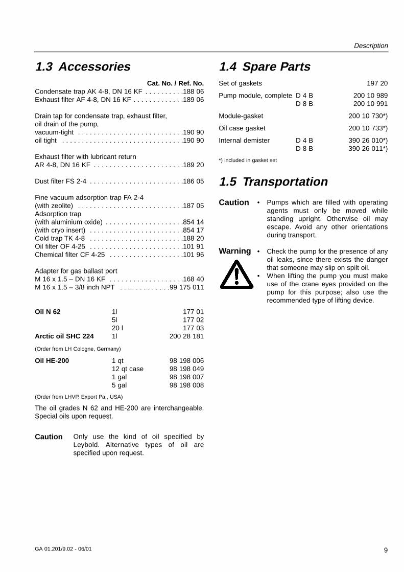
1.6 Technical Data
We can only guarantee that the pump willmeet its specifications when using the typeof lubricant which has been specified by us.
Caution
TRIVAC D 4 B TRIVAC D 8 B50 Hz 60 Hz 50 Hz 60 Hz
Nominal pumping speed 1) m3 x h-1 (cfm)
Pumping speed 1) m3 x h-1 (cfm)
Ultimate partial pressure
without gas ballast 1) mbar (Torr)
Ultimate total pressure without gas ballast 1)mbar (Torr)
Ultimate total pressure with gas ballast 1)mbar (Torr)
Water vapor tolerance 1) mbar (Torr)
Water vapor capacity gm/h
Oil filling, min./max. l (qt)
Noise level * to DIN 45 635,
without/with gas ballast dB(A)
Admissible ambient temperature °C (°F)
Motor rating * W (HP)
Nominal speed rpm
Type of protection IP
Weight* kg (lbs)
Connections, Intake and Exhaust DN
1) To DIN 28 400 and following numbers
* Weight, motor rating and noise levels for the pumps with 230 V, 50 Hz AC motor only.
4.8 (2.8) 5.8 (3.4) 9.7 (5.7) 11.6 (6.9)
4.2 (2.5) 5 (3) 8.5 (5) 10.2 (6)
10-4 (0.75 x 10⁻⁴)
< 2 x 10⁻³ (< 1.5 x 10⁻³)
< 5 x 10⁻³ (< 3.8 x 10⁻³)
30 (22.5) 25 (18.8)
93 157
0.3 / 0.8 (.3 / .85) 0.3 / 0.9 (.3 / .95)
50 / 52
12 - 40 (54 - 104)
370 (.50)
1500 1800 1500 1800
54
18.7 (41.2) 21.2 (46.7)
16 KF
mbar
10-1
100
101
102
-510 -410 -310 10-2 10-1 100 101 103
D 8 B
D 4 B
Pressure
Pum
ping
spe
ed
m x h3 -1
50
cfm
10.5
510
0.1
Torr-510 -410 -310 10-2 10-1 1 10 750
Fig. 5 Pumping speed characteristics at 50 Hz (60 Hz curves at the end of the section)
Ultimate partial pressure without gas ballastUltimate total pressure without gas ballastUltimate total pressure with gas ballast
Description
11GA 01.201/9.02 - 06/01
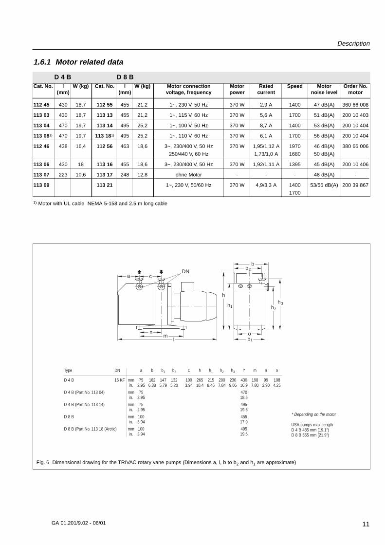
Fig. 6 Dimensional drawing for the TRIVAC rotary vane pumps (Dimensions a, l, b to b2 and h1 are approximate)
1) Motor with UL cable NEMA 5-158 and 2.5 m long cable
b2b
h1
h
h2
b1
h3
ol
mn
DNca
Type DN a b b1 b2 c h h1 h2 h3 l* m n o
D 4 B 16 KF mm 75 162 147 132 100 265 215 200 230 430 198 99 108in. 2.95 6.38 5.79 5.20 3.94 10.4 8.46 7.84 9.06 16.9 7.80 3.90 4.25
D 4 B (Part No. 113 04) mm 75 470in. 2.95 18.5
D 4 B (Part No. 113 14) mm 75 495in. 2.95 19.5
D 8 B mm 100 455in. 3.94 17.9
D 8 B (Part No. 113 18 (Arctic) mm 100 495in. 3.94 19.5
* Depending on the motor
USA pumps max. lengthD 4 B 485 mm (19.1“)D 8 B 555 mm (21.9“)
D 4 B D 8 B
1.6.1 Motor related data
Cat. No. l W (kg) Cat. No. l W (kg) Motor connection Motor Rated Speed Motor Order No.(mm) (mm) voltage, frequency power current noise level motor
112 45 430 18,7 112 55 455 21.2 1~, 230 V, 50 Hz 370 W 2,9 A 1400 47 dB(A) 360 66 008
113 03 430 18,7 113 13 455 21,2 1~, 115 V, 60 Hz 370 W 5,6 A 1700 51 dB(A) 200 10 403
113 04 470 19,7 113 14 495 25,2 1~, 100 V, 50 Hz 370 W 8,7 A 1400 53 dB(A) 200 10 404
113 081) 470 19,7 113 181) 495 25,2 1~, 110 V, 60 Hz 370 W 6,1 A 1700 56 dB(A) 200 10 404
112 46 438 16,4 112 56 463 18,6 3~, 230/400 V, 50 Hz 370 W 1,95/1,12 A 1970 46 dB(A) 380 66 006
250/440 V, 60 Hz 1,73/1,0 A 1680 50 dB(A)
113 06 430 18 113 16 455 18,6 3~, 230/400 V, 50 Hz 370 W 1,92/1,11 A 1395 45 dB(A) 200 10 406
113 07 223 10,6 113 17 248 12,8 ohne Motor - - - 48 dB(A) -
113 09 113 21 1~, 230 V, 50/60 Hz 370 W 4,9/3,3 A 1400 53/56 dB(A) 200 39 867
1700
Operation
12 GA 01.201/9.02 - 06/01
2.1 InstallationThe standard pump (except the versionsequipped with an explosion hazard ratedmotor) is not suited for installation inexplosion hazard areas. When planningsuch an application please contact us first.
The TRIVAC-B pump can be set up on a flat, horizontalsurface. Rubber feet under the coupling housing ensurethat the pump can not slip.
If you wish firmly install the pump in place, insert boltsthrough bore holes in the rubber feet.
Max. tilt for the pump (without furtherattachment) with possibly fitted standardaccessories is 10ϒ from the vertical.
The rubber feet act as vibration absorbers.They must therefore not be compressed byscrews. When installing the TRIVAC-Bpump, make sure that the connections andcontrols are readily accessible.
The site chosen should allow adequate aircirculation to cool the pump (keep front and rear unobstructed). The ambienttemperature should not exceed +40 ϒC(104 ϒF) and not drop below +12 ϒC (55ϒF) (see Section 2.5.3).The max. amount of heat given offapproximately corresponds to the ratedmotor power.
2.2 Connection to theSystem
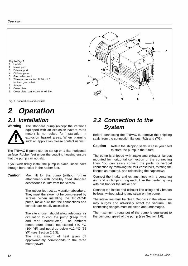
Before connecting the TRIVAC-B, remove the shippingseals from the connection flanges (7/2) and (7/3).
Retain the shipping seals in case you needto store the pump in the future.
The pump is shipped with intake and exhaust flangesmounted for horizontal connection of the connectinglines. You can easily convert the ports for verticalconnection by removing the four capscrews, rotating theflanges as required, and reinstalling the capscrews.
Connect the intake and exhaust lines with a centeringring and a clamping ring each. Use the centering ringwith dirt trap for the intake port.
Connect the intake and exhaust line using anti-vibrationbellows, without placing any strain on the pump.
The intake line must be clean. Deposits in the intake linemay outgas and adversely affect the vacuum. Theconnecting flanges must be clean and undamaged.
The maximum throughput of the pump is equivalent tothe pumping speed of the pump (see Section 1.6).
2 OperationFig. 7 Connections and controls
Key to Fig. 71 Handle2 Intake port3 Exhaust port4 Oil-level glass5 Gas ballast knob6 Threaded connection M 16 x 1.5
for inert gas ballast7 Adapter8 Cover plate9 Cover plate; connection for oil filter
Caution
Caution
Warning
Operation
13GA 01.201/9.02 - 06/01
The cross-section of the intake and exhaustlines should be at least the same size asthe connection ports of the pump. If theintake line is too narrow, it reduces thepumping speed. If the exhaust line is toonarrow, overpressures may occur in thepump; this might damage the shaft sealsand cause oil leaks.The maximum pressurein the oil case must not exceed 1.5 bar(absolute).
When pumping vapours, it is advisable toinstall condensate traps on the intake andexhaust sides.
Install the exhaust line with a downwardslope (lower than the pump) so as toprevent condensate from flowing back intothe pump. If this is not possible, insert acondensate trap.
The exhaust gases from the vacuum pumpmust be safely lead away and subjected topost-treatment as required. In order toreduce the emission of oil vapours werecommend the installation of an additionalexhaust filter (Leybold accessory).
Depending on the type of application or thekind of pumped media, the correspondingregulations and information sheets must beobserved.
The pumps may be operated with an inert gas ballast viaa connection which is provided for this purpose. Thecover plate (7/8) can be removed to gain access to thisM 16 x 1.5 threaded port (7/6). Matching connectors areavailable (see Section 1.3).
In inlet pressure for the gas ballast should be about 1000mbar (absolute) and sufficient quantities of gas must beavailable (about 1/10 of the pumping speed).
Never operate the pump with a sealedexhaust line. There is the danger of injury.
Before starting any work on the pump, thepersonnel must be informed about possibledangers first. All safety regulations must beobserved.
2.3 Electrical ConnectionsBefore wiring the motor or altering thewiring, ensure that mains supply for thepump is off and that it can not be appliedinadvertently.
In order to prevent the pump from runningup unexpectedly after a mains powerfailure, the pump must be integrated in thecontrol system in such a way that the pumpcan only be switched on again manually.This applies equally to emergency cut-outarrangements.
Electrical connections must be done by aqualified electrician as defined by VDE0105 in accordance with the VDE 0100guidelines.Observe all safety regulations.
TRIVAC-B pumps are available with a single-phase or athree-phase AC motor.
2.3.1 Pump with Single-Phase AC Motor
Pumps equipped with a single-phase AC motor may beconnected directly to the mains via the mains cord andthe mains plug.
At 230 V use at least a 6 A slow-blow or a 10 A fast-blowfuse.
The direction of rotation need not be checked as it isfixed.
The motor is protected against overloading by a thermaloverload switch with automatic resetting.
If the thermal overload protector shuts offthe pump, the motor will restart itself assoon as it cools. That’s why the mains plugshould be disconnected from the mainsbefore starting with any work on the pump.
2.3.2 Pump with Three-Phase AC Motor
TRIVAC-B pumps with a three-phase motor are suppliedwithout accessories for the electrical connection. Theymust be connected via the appropriate cable, and asuitable motor protection switch. Set the switch inaccordance with the rating on the motor nameplate.
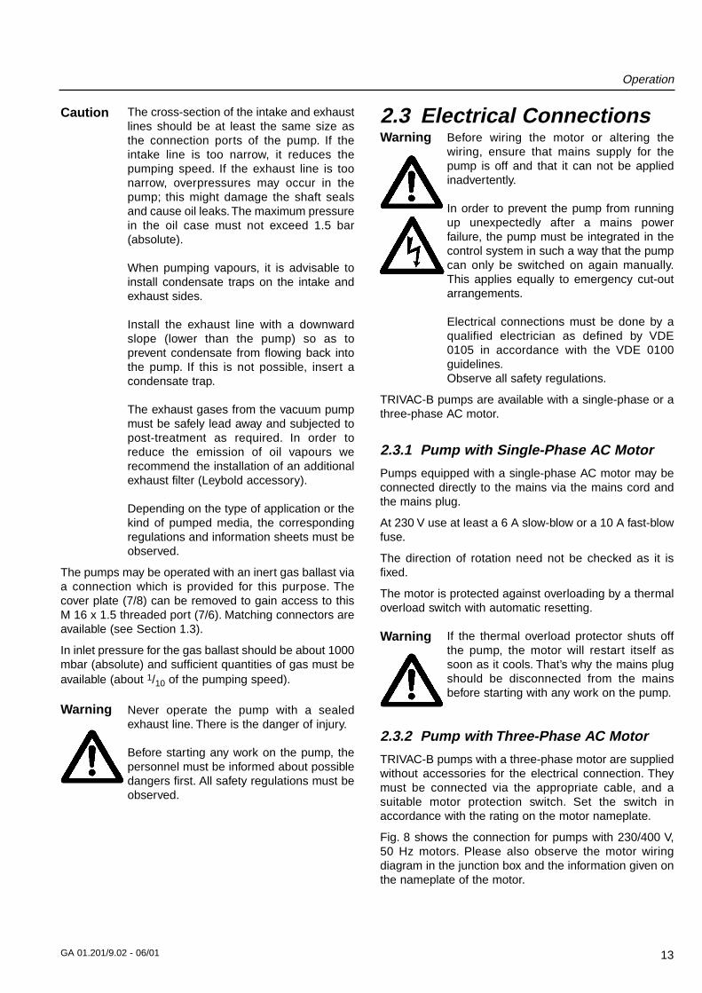
Fig. 8 shows the connection for pumps with 230/400 V,50 Hz motors. Please also observe the motor wiringdiagram in the junction box and the information given onthe nameplate of the motor.
Warning
Warning
Caution
Warning
Operation
14 GA 01.201/9.02 - 06/01
After connecting the motor and after everytime you alter the wiring, check the directionof rotation. To do so, briefly switch on themotor and check whether a suitable cover(e. g. a blank flange) is sucked on at theintake port. If not, interchange two phasesof the connection.Observe the direction arrow on the couplinghousing.
2.4 Start-upEach time before starting up ensure that the oil level isvisible in the oil level glass.
For pumps with 3-phase motors, check the direction ofrotation before starting the pump
for the first time and after each change in the electricalconnection (see Section 2.3.2).
On initial start-up, after prolonged idle periods or after anoil change, the specified ultimate pressure cannot beattained immediately until the oil is degassed. This canbe done by running the pump for approx. 30 min. with theintake line closed and the gas ballast valve (7/5) open.
Before starting the pump ensure that thepump and the fitted accessories meet therequirements of your application and thatsafe operation can be guaranteed.
Avoid exposure of any part of the body tothe vacuum. There is the danger of injury.Never operate the pump with an openintake port. Vacuum connections as well asoil-fill and oil-drain openings must never beopened during operation.
The safety regulations which apply to theapplication in each case must be observed.This applies to installation, operation andduring maintenance (service) as well aswaste disposal and transportation.The standard pump is not suited forpumping of hazardous gases or vapours.
Our technical sales department is available for furtheradvice in these matters.
2.4.1 Areas of Application
Before pumping oxygen (or other highlyreactive gases) at concentrationsexceeding the concentration in theatmosphere (> 21 % for oxygen) it will be necessary touse a special pump. Such a pump will haveto be modified and de-greased, and an inertspecial lubricant (like PFPE) must be used.
The pump is not suitable for pumping of:
– ignitable and explosive gases or vapours– oxidants– pyrophorous gases.
The pumps are not suitable for pumping ofliquids or very dusty media. Suitableprotective devices must be installed.
Our technical sales department is available for furtheradvice in these matters.
Fig. 8 Connection diagram for TRIVAC-B with 50 Hz 3-phase motor
Delta connection Star connection
Caution
Warning
Warning
Caution
Warning
Operation
15GA 01.201/9.02 - 06/01
2.5 OperationTRIVAC-B pumps can pump condensable gases andvapours, provided that the gas ballast valve (7/5) is openand the pump has attained its operating temperature.
2.5.1 Pumping of Non-Condensable Gases
If the process contains mainly permanent gases, thepump may be operated without gas ballast (position 0),provided that the saturation vapour pressure at operatingtemperature is not exceeded during compression.
If the composition of the gases to be pumped is notknown and if condensation in the pump cannot be ruledout, run the pump with the gas ballast valve open inaccordance with Section 2.5.2.
2.5.2 Pumping of Condensable Gases and Vapours
With the gas ballast valve open (position I) and atoperating temperature, TRIVAC-B pumps can pump purewater vapour up to the water vapour tolerance specifiedby the technical data. If the vapour pressure increasesabove the permissible level, the water vapour willcondense in the oil of the pump.
When pumping vapours ensure that the gas ballast valveis open and that the pump has been warmed up forapproximately 30 minutes with the intake line closed.
Vapour phases may only be pumped up tothe permissible limit after the pump hasattained its operating temperature.
During pumping, vapours may dissolve inthe oil. This changes the oil’s properties andthus there is a risk of corrosion in the pump.Therefore, don’t switch off the TRIVAC-Bimmediately after completion of theprocess. Instead, allow the pump tocontinue operating with the gas ballastvalve open and the intake line closed untilthe oil is free of condensed vapours. Westrongly recommend operating the TRIVAC-B in this mode for about 30 minutes aftercompletion of the process.
In cyclic operation, the TRIVAC-B should not be switchedoff during the intervals between the individual workingphases (power consumption is minimal when the pumpis operating at ultimate pressure), but should continue torun with gas ballast valve open and intake port closed (ifpossible via a valve).
Once all vapours have been pumped off from a process(e.g. during drying), the gas ballast valve can be closedto improve the attainable ultimate pressure.
2.5.3 Operating Temperature
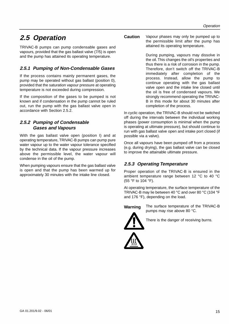
Proper operation of the TRIVAC-B is ensured in theambient temperature range between 12 °C to 40 °C(55 °F to 104 °F).
At operating temperature, the surface temperature of theTRIVAC-B may lie between 40 °C and over 80 °C (104 °Fand 176 °F), depending on the load.
The surface temperature of the TRIVAC-Bpumps may rise above 80 °C.
There is the danger of receiving burns.
Warning
Caution
Operation
16 GA 01.201/9.02 - 06/01
2.6 Switching Off/ShutdownUnder normal circumstances, all that you need do is toelectrically switch off the TRIVAC-B.
No further measures will be required.
When pumping condensable media let the pumpcontinue to operate with the gas ballast valve open andthe intake line closed before switching off (see Section2.5.2).
When pumping aggressive or corrosive media, let thepump continue to operate even during long non-workingintervals (e.g. overnight) with the intake line closed andthe gas ballast valve open. This avoids corrosion duringidle periods.
If the TRIVAC-B is to be shutdown for an extended periodafter pumping aggressive or corrosive media or if thepump has to be stored, proceed as follows:
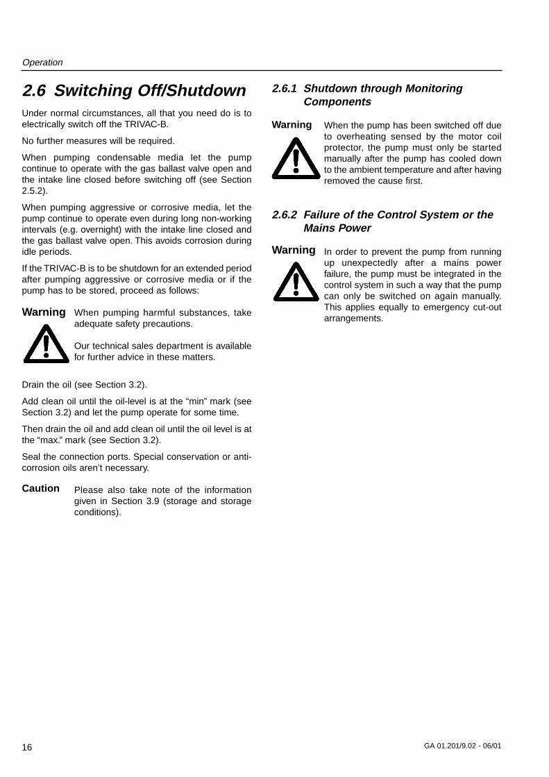
When pumping harmful substances, takeadequate safety precautions.
Our technical sales department is availablefor further advice in these matters.
Drain the oil (see Section 3.2).
Add clean oil until the oil-level is at the “min” mark (seeSection 3.2) and let the pump operate for some time.
Then drain the oil and add clean oil until the oil level is atthe “max.” mark (see Section 3.2).
Seal the connection ports. Special conservation or anti-corrosion oils aren’t necessary.
Please also take note of the informationgiven in Section 3.9 (storage and storageconditions).
2.6.1 Shutdown through MonitoringComponents
When the pump has been switched off dueto overheating sensed by the motor coilprotector, the pump must only be startedmanually after the pump has cooled downto the ambient temperature and after havingremoved the cause first.
2.6.2 Failure of the Control System or theMains Power
In order to prevent the pump from runningup unexpectedly after a mains powerfailure, the pump must be integrated in thecontrol system in such a way that the pumpcan only be switched on again manually.This applies equally to emergency cut-outarrangements.
Caution
Warning
Warning
Warning
Maintenance
17GA 01.201/9.02 - 06/01
3 MaintenanceDisconnect the electrical connectionsbefore disassembling the pump. Makeabsolutely sure that the pump cannot beaccidentally started.
If the pump has pumped harmfulsubstances, contrary to what has beenstated in Section 2.4, ascertain the natureof hazard and take adequate safetymeasures.Observe all safety regulations.
If you send a pump to LEYBOLD for repair pleaseindicate any harmful substances existing in or around thepump. A form is available from LEYBOLD for thispurpose.
When disposing of used oil, you mustobserve the applicable environmentalregulations!
Due to the design concept, TRIVAC-B pumps requirevery little maintenance when operated under normalconditions. The work required is described in thesections below. In addition to this, a maintenance plan isprovided in Section 3.11.
All work must be carried out by suitablytrained personnel. Maintenance or repairscarried out incorrectly will affect the life andperformance of the pump and may causeproblems when filing warranty claims.
For the spare part numbers please refer tothe enclosed spare parts list.In case of special versions please alwaysstate the special number, model numberand the serial number.
LEYBOLD offers practical courses on the maintenance,repair, and testing of TRIVAC-B pumps. Further detailsare available from LEYBOLD on request.
If the TRIVAC-B is used in ambient airwhich is much contaminated, make surethat the air circulation and the gas ballastvalve are not adversely affected.
When the TRIVAC-B has been pumpingcorrosive media, we recommend to performany possibly planned maintenance workimmediately in order to prevent corrosion ofthe pump while at standstill.
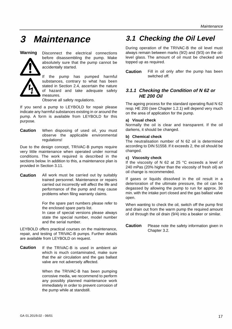
3.1 Checking the Oil LevelDuring operation of the TRIVAC-B the oil level mustalways remain between marks (9/2) and (9/3) on the oil-level glass. The amount of oil must be checked andtopped up as required.
Fill in oil only after the pump has beenswitched off.
3.1.1 Checking the Condition of N 62 orHE 200 Oil
The ageing process for the standard operating fluid N 62resp. HE 200 (see Chapter 1.2.1) will depend very muchon the area of application for the pump.
a) Visual checkNormally the oil is clear and transparent. If the oil darkens, it should be changed.
b) Chemical checkThe neutralisation number of N 62 oil is determinedaccording to DIN 51558. If it exceeds 2, the oil should bechanged.
c) Viscosity checkIf the viscosity of N 62 at 25 °C exceeds a level of 240 mPas (20% higher than the viscosity of fresh oil) anoil change is recommended.
If gases or liquids dissolved in the oil result in adeterioration of the ultimate pressure, the oil can bedegassed by allowing the pump to run for approx. 30min. with the intake port closed and the gas ballast valveopen.
When wanting to check the oil, switch off the pump firstand drain out from the warm pump the required amountof oil through the oil drain (9/4) into a beaker or similar.
Please note the safety information given inChapter 3.2.
Caution
Caution
Caution
Caution
Warning
Caution
Maintenance
18 GA 01.201/9.02 - 06/01
3.2 Oil ChangeBefore pumping oxygen (or other highlyreactive gases) at concentrationsexceeding the concentration in theatmosphere (> 21 % for oxygen) it will be necessary touse a special pump. Such a pump will haveto be modified and de-greased, and an inertspecial lubricant (like PFPE) must be used.
Hazardous substances may escape fromthe pump and the oil. Take adequate safetyprecautions. For example wear gloves, faceprotection or breathing protection.
Observe all safety regulations.
For proper operation of the pump, it is essential that thepump has an adequate supply of the correct and cleanoil at all times.
The oil must be changed when it looks dirty or if itappears chemically or mechanically worn out (seeSection 3.1.1).
The oil should be changed after the first 100 operatinghours and then at least every 2,000 to 3,000 operatinghours or after one year. At high intake pressures andintake temperatures and/or when pumping contaminatedgases, the oil will have to be changed more frequently.
Further oil changes should be made before and afterlong-term storage of the pump.
If the oil becomes contaminated too quickly, install a dustfilter and/or oil filter (see Section 1.3). Contact us formore information in this matter.
Only change the oil after the pump hasbeen switched off and while the pump is stillwarm.
Required tool: Allen key 8 mm.
Remove the oil-drain plug (9/4) and let the used oil draininto a suitable container. When the flow of oil slowsdown, screw the oil-drain plug back in, briefly switch onthe pump (max. 10 s) and then switch it off again.Remove the oil-drain plug once more and drain out theremaining oil.
Screw the oil-drain plug back in (check the gasket andreinstall a new one if necessary).
Remove the oil-fill plug (9/1) and fill in with fresh oil.
Screw the oil-fill plug (9/1) back in.
If there is the danger that the operatingagent may present a hazard in any way dueto decomposition of the oil, or because ofthe media which have been pumped, youmust determine the kind of hazard andensure that all necessary safetyprecautions are taken.
We can only guarantee that the pumpoperates as specified by the technical dataif the lubricants recommended by us areused.
3.3 Cleaning the Dirt TrapA wire-mesh sieve is located in the intake port of thepump to act as a dirt trap for coarse particles. It shouldbe kept clean to avoid a reduction of the pumping speed.
For this purpose, remove the dirt trap (2/2) from theintake port and rinse it in a suitable vessel with solvent.Then thoroughly dry it with compressed air. If the dirt trapis defective, replace it with a new one.
The cleaning intervals depend on theapplication. If the pump is exposed to largeamounts of abrasive materials, a dust filtershould be fitted into the intake line.
CautionCaution
Fig. 9 Oil change
Key to Fig. 91 Oil-fill plug2 Oil-level mark maximum3 Oil-level mark minimum4 Oil-drain plug
1
2
3
4
Warning
Warning
Caution
Maintenance
19GA 01.201/9.02 - 06/01
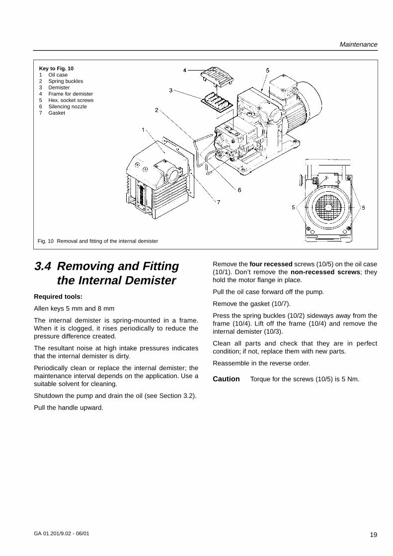
3.4 Removing and Fittingthe Internal Demister
Required tools:
Allen keys 5 mm and 8 mm
The internal demister is spring-mounted in a frame.When it is clogged, it rises periodically to reduce thepressure difference created.
The resultant noise at high intake pressures indicatesthat the internal demister is dirty.
Periodically clean or replace the internal demister; themaintenance interval depends on the application. Use asuitable solvent for cleaning.
Shutdown the pump and drain the oil (see Section 3.2).
Pull the handle upward.
Remove the four recessed screws (10/5) on the oil case(10/1). Don’t remove the non-recessed screws; theyhold the motor flange in place.
Pull the oil case forward off the pump.
Remove the gasket (10/7).
Press the spring buckles (10/2) sideways away from theframe (10/4). Lift off the frame (10/4) and remove theinternal demister (10/3).
Clean all parts and check that they are in perfectcondition; if not, replace them with new parts.
Reassemble in the reverse order.
Torque for the screws (10/5) is 5 Nm.Caution
Fig. 10 Removal and fitting of the internal demister
Key to Fig. 101 Oil case2 Spring buckles3 Demister4 Frame for demister5 Hex. socket screws6 Silencing nozzle7 Gasket
Maintenance
20 GA 01.201/9.02 - 06/01
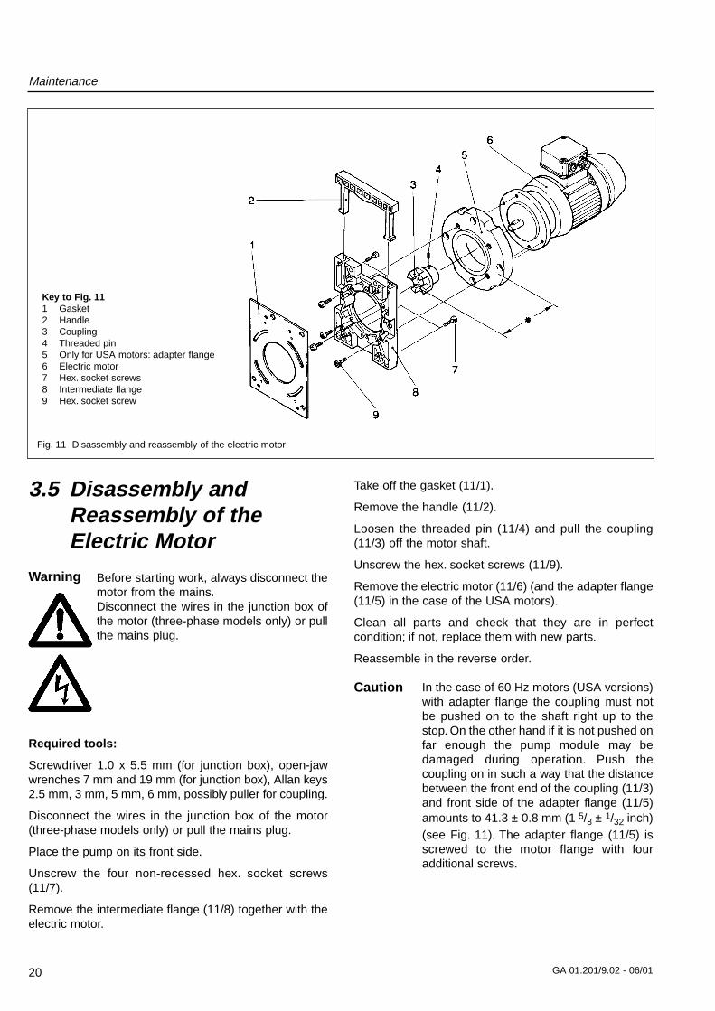
3.5 Disassembly andReassembly of theElectric Motor
Before starting work, always disconnect themotor from the mains.Disconnect the wires in the junction box ofthe motor (three-phase models only) or pullthe mains plug.
Required tools:
Screwdriver 1.0 x 5.5 mm (for junction box), open-jawwrenches 7 mm and 19 mm (for junction box), Allan keys2.5 mm, 3 mm, 5 mm, 6 mm, possibly puller for coupling.
Disconnect the wires in the junction box of the motor(three-phase models only) or pull the mains plug.
Place the pump on its front side.
Unscrew the four non-recessed hex. socket screws(11/7).
Remove the intermediate flange (11/8) together with theelectric motor.
Take off the gasket (11/1).
Remove the handle (11/2).
Loosen the threaded pin (11/4) and pull the coupling(11/3) off the motor shaft.
Unscrew the hex. socket screws (11/9).
Remove the electric motor (11/6) (and the adapter flange(11/5) in the case of the USA motors).
Clean all parts and check that they are in perfectcondition; if not, replace them with new parts.
Reassemble in the reverse order.
In the case of 60 Hz motors (USA versions)with adapter flange the coupling must notbe pushed on to the shaft right up to thestop. On the other hand if it is not pushed onfar enough the pump module may bedamaged during operation. Push thecoupling on in such a way that the distancebetween the front end of the coupling (11/3)and front side of the adapter flange (11/5)amounts to 41.3 ± 0.8 mm (1 5/8 ± 1/32 inch)(see Fig. 11). The adapter flange (11/5) isscrewed to the motor flange with fouradditional screws.
Caution
Fig. 11 Disassembly and reassembly of the electric motor
Key to Fig. 111 Gasket2 Handle3 Coupling4 Threaded pin5 Only for USA motors: adapter flange 6 Electric motor7 Hex. socket screws8 Intermediate flange9 Hex. socket screw
Warning
Maintenance
21GA 01.201/9.02 - 06/01
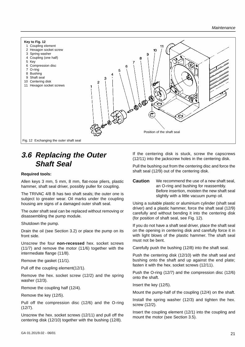
3.6 Replacing the OuterShaft Seal
Required tools:
Allen keys 3 mm, 5 mm, 8 mm, flat-nose pliers, plastichammer, shaft seal driver, possibly puller for coupling.
The TRIVAC 4/8 B has two shaft seals; the outer one issubject to greater wear. Oil marks under the couplinghousing are signs of a damaged outer shaft seal.
The outer shaft seal can be replaced without removing ordisassembling the pump module.
Shutdown the pump.
Drain the oil (see Section 3.2) or place the pump on itsfront side.
Unscrew the four non-recessed hex. socket screws(11/7) and remove the motor (11/6) together with theintermediate flange (11/8).
Remove the gasket (11/1).
Pull off the coupling element(12/1).
Remove the hex. socket screw (12/2) and the springwasher (12/3).
Remove the coupling half (12/4).
Remove the key (12/5).
Pull off the compression disc (12/6) and the O-ring(12/7).
Unscrew the hex. socket screws (12/11) and pull off thecentering disk (12/10) together with the bushing (12/8).
If the centering disk is stuck, screw the capscrews(12/11) into the jackscrew holes in the centering disk.
Pull the bushing out from the centering disc and force theshaft seal (12/9) out of the centering disk.
We recommend the use of a new shaft seal,an O-ring and bushing for reassembly.Before insertion, moisten the new shaft sealslightly with a little vacuum pump oil.
Using a suitable plastic or aluminium cylinder (shaft sealdriver) and a plastic hammer, force the shaft seal (12/9)carefully and without bending it into the centering disk(for position of shaft seal, see Fig. 12).
If you do not have a shaft seal driver, place the shaft sealon the opening in centering disk and carefully force it inwith light blows of the plastic hammer. The shaft sealmust not be bent.
Carefully push the bushing (12/8) into the shaft seal.
Push the centering disk (12/10) with the shaft seal andbushing onto the shaft and up against the end plate;fasten it with the hex. socket screws (12/11).
Push the O-ring (12/7) and the compression disc (12/6)onto the shaft.
Insert the key (12/5).
Mount the pump-half of the coupling (12/4) on the shaft.
Install the spring washer (12/3) and tighten the hex.screw (12/2).
Insert the coupling element (12/1) into the coupling andmount the motor (see Section 3.5).
Caution
Fig. 12 Exchanging the outer shaft seal
Key to Fig. 121 Coupling element2 Hexagon socket screw3 Spring washer4 Coupling (one half)5 Key6 Compression disc7 O-ring8 Bushing9 Shaft seal
10 Centering disk11 Hexagon socket screws
Position of the shaft seal
Maintenance
22 GA 01.201/9.02 - 06/01
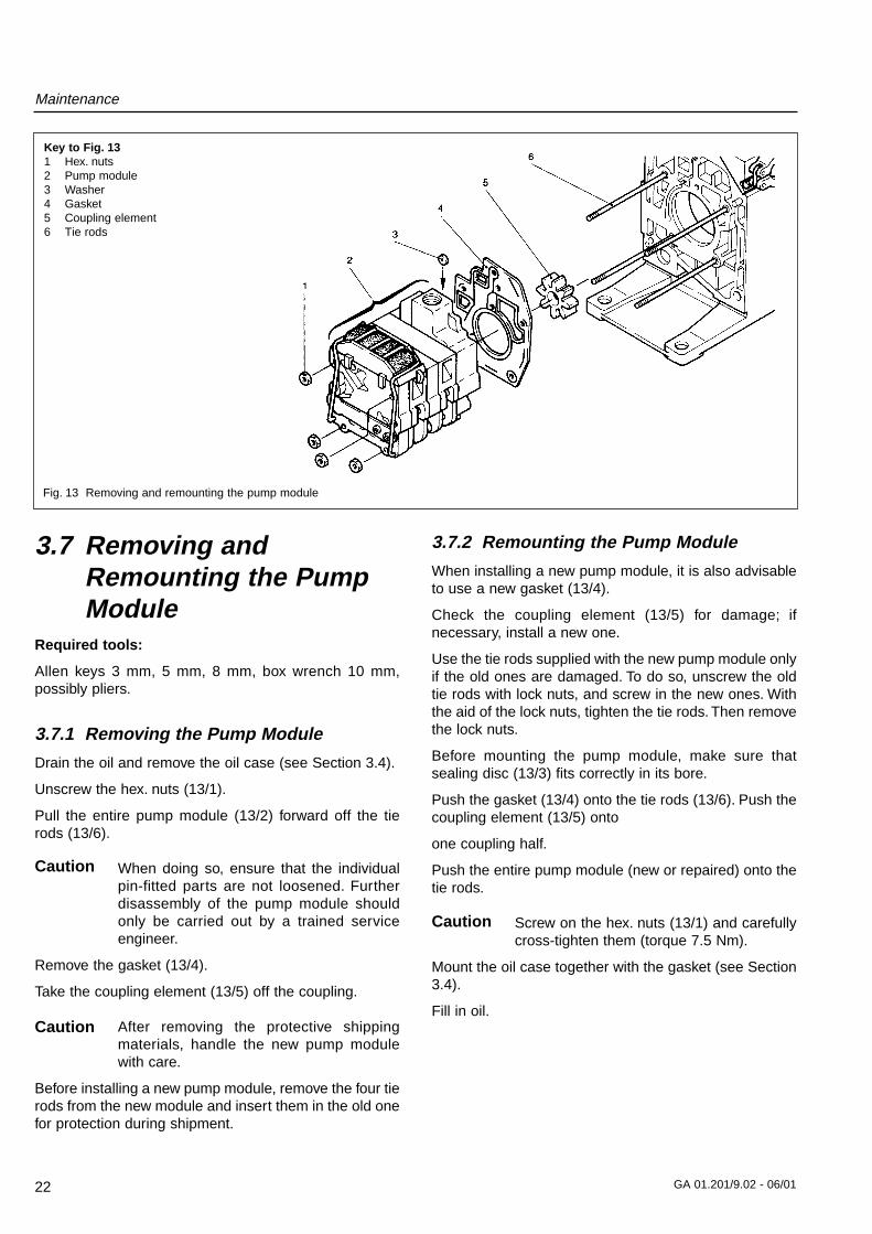
3.7.2 Remounting the Pump Module
When installing a new pump module, it is also advisableto use a new gasket (13/4).
Check the coupling element (13/5) for damage; ifnecessary, install a new one.
Use the tie rods supplied with the new pump module onlyif the old ones are damaged. To do so, unscrew the oldtie rods with lock nuts, and screw in the new ones. Withthe aid of the lock nuts, tighten the tie rods. Then removethe lock nuts.
Before mounting the pump module, make sure thatsealing disc (13/3) fits correctly in its bore.
Push the gasket (13/4) onto the tie rods (13/6). Push thecoupling element (13/5) onto
one coupling half.
Push the entire pump module (new or repaired) onto thetie rods.
Screw on the hex. nuts (13/1) and carefullycross-tighten them (torque 7.5 Nm).
Mount the oil case together with the gasket (see Section3.4).
Fill in oil.
3.7 Removing andRemounting the PumpModule
Required tools:
Allen keys 3 mm, 5 mm, 8 mm, box wrench 10 mm,possibly pliers.
3.7.1 Removing the Pump Module
Drain the oil and remove the oil case (see Section 3.4).
Unscrew the hex. nuts (13/1).
Pull the entire pump module (13/2) forward off the tierods (13/6).
When doing so, ensure that the individualpin-fitted parts are not loosened. Furtherdisassembly of the pump module shouldonly be carried out by a trained serviceengineer.
Remove the gasket (13/4).
Take the coupling element (13/5) off the coupling.
After removing the protective shippingmaterials, handle the new pump modulewith care.
Before installing a new pump module, remove the four tierods from the new module and insert them in the old onefor protection during shipment.
Fig. 13 Removing and remounting the pump module
Key to Fig. 131 Hex. nuts2 Pump module3 Washer4 Gasket5 Coupling element6 Tie rods
Caution
Caution
Caution
Maintenance
23GA 01.201/9.02 - 06/01
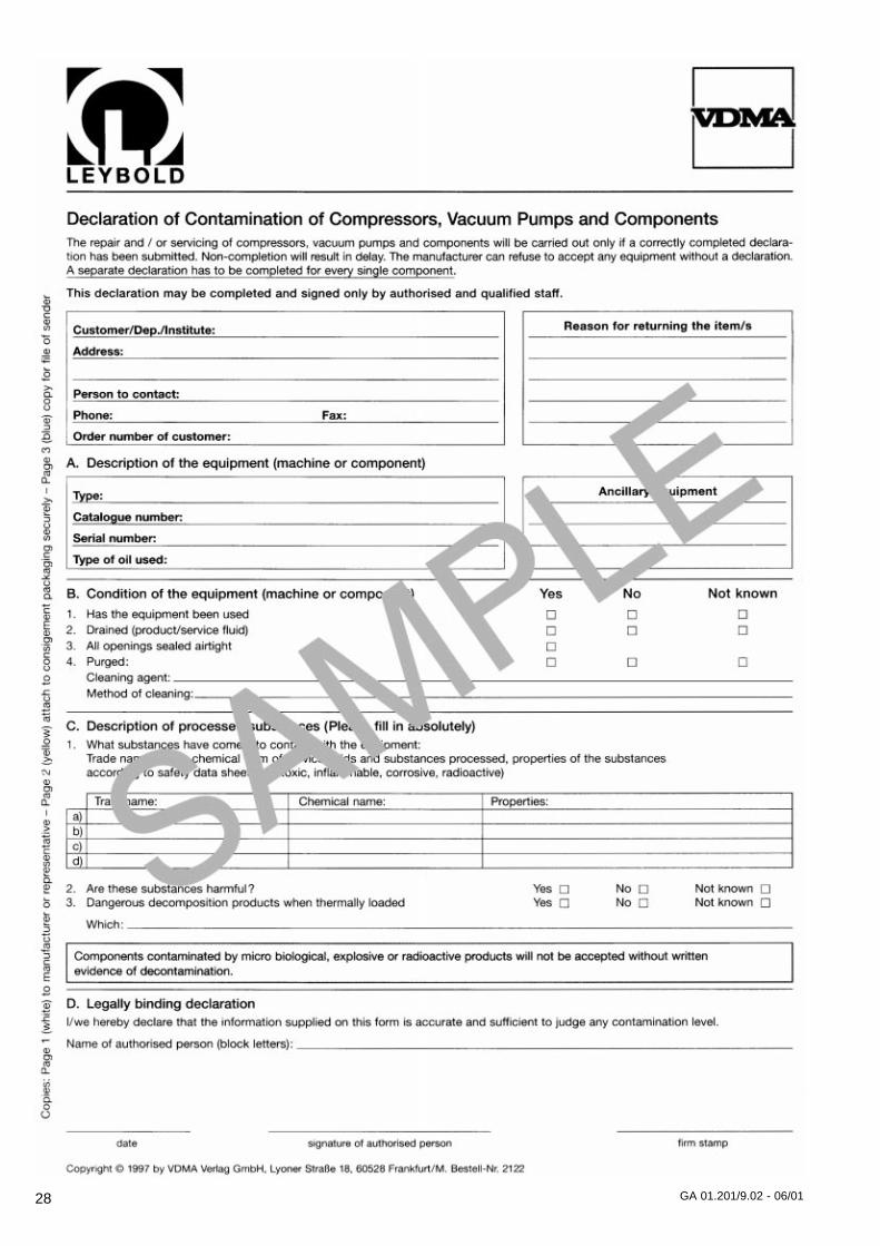
3.8 Leybold ServiceIf a pump is returned to Leybold, indicate whether thepump free of substances damaging to health or whetherit is contaminated.
If it is contaminated also indicate the nature of thehazard. For this you must use a form which has beenprepared by us which we will provide upon request.
A copy of this form is reproduced at the end of theseOperating Instructions: “Declaration of Contamination ofVacuum Instruments and Components”.
Please attach this form to the pump or enclose it with thepump.
This “Declaration of Contamination” is required to meetGerman Law and to protect our personnel.
Leybold must return any pumps without a “Declaration ofContamination” to the sender’s address.
The pump must be packed in such a way,that it will not be damaged during shippingand so that any contaminants are notreleased from the package.
3.8.1 Waste Disposal of Used Pump Materials
The corresponding environmental and safety regulationsapply. This applies equally to used filters and filterelements (oil filter, exhaust filter and dust filter).
– In the case of hazardous substancesdetermine the kind of hazard first andobserve the applicable safetyregulations. If the potential hazard stillpersists, the pump must bedecontaminated before starting with anymaintenance work. For professionaldecontamination we recommend ourLeybold service.
– Never exchange the oil or the filterswhile the pump is still warm. Let thepump cool down to uncriticaltemperatures first. You must wearsuitable protective clothing.
Warning
Warning
3.9 Storing the Pump
Before putting a pump into operation oncemore it should be stored in a dry placepreferably at room temperature (20 °C).Before the pump is shelved it must beproperly disconnected from the vacuumsystem, purged with dry nitrogen and the oilshould be changed too.
The inlets and outlets of the pump must besealed with the shipping seals which areprovided upon delivery.The gas ballast switch must be set to the “0”position and if the pump is to be shelved fora longer period of time it should be sealedin a PE bag containing some desiccant(silica gel).
When a pump is put into operation after it has beenshelved for over one year, standard maintenance shouldbe run on the pump and the oil should also beexchanged (see Operating Instructions). We recommendthat you contact the Leybold service.
Caution
Maintenance
24 GA 01.201/9.02 - 06/01
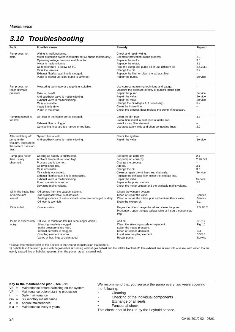
3.10 TroubleshootingFault Possible cause Remedy Repair*
Pump does notstart.
Pump does notreach ultimatepressure.
Wiring is malfunctioning.Motor protection switch incorrectly set (3-phase motors only).Operating voltage does not match motor.Motor is malfunctioning.Oil temperature is below 12 ϒC.Oil is too viscous.Exhaust filter/exhaust line is clogged.Pump is seized up (sign: pump is jammed).
Check and repair wiring.Set motor protection switch properly.Replace the motor.Replace the motor.Heat the pump and pump oil or use different oil.Change the oil.Replace the filter or clean the exhaust line.Repair the pump.
–2.33.53.52.5.3/3.23.2–Service
Measuring technique or gauge is unsuitable.
External leak1).Anti-suckback valve is malfunctioning.Exhaust valve is malfunctioning.Oil is unsuitable.Intake line is dirty.Pump is too small.
Use correct measuring technique and gauge.Measure the pressure directly at pump’s intake port.Repair the pump.Repair the valve.Repair the valve.Change the oil (degas it, if necessary).Clean the intake line.Check the process data; replace the pump, if necessary.
–
ServiceServiceService3.2––
Pumping speed istoo low.
Dirt trap in the intake port is clogged.
Exhaust filter is clogged.Connecting lines are too narrow or too long.
Clean the dirt trap;Precaution: install a dust filter in intake line.Install a new filter element.Use adequately wide and short connecting lines.
3.3
–2.2
Pump gets hotterthan usuallyobserved.
Cooling air supply is obstructed.Ambient temperature is too high.Process gas is too hot.Oil level is too low.Oil is unsuitable.Oil cycle is obstructed.Exhaust filter/exhaust line is obstructed.Exhaust valve is malfunctioning.Pump module is worn out.Deviating mains voltage.
Set pump up correctly.Set pump up correctly.Change the process.Add oil.Change the oil.Clean or repair the oil lines and channels.Replace the exhaust filter, clean the exhaust line.Repair the valve.Replace the pump module.Check the motor voltage and the available mains voltage.
Oil is turbid. Condensation. Degas the oil or change the oil and clean the pump.Precaution: open the gas ballast valve or insert a condensatetrap.
2.5.2/3.2
2.12.1/2.5.3–3.13.2Service–Service3.7
Pump is excessivelynoisy.
Oil level is much too low (oil is no longer visible).Silencing nozzle is clogged.Intake pressure is too high.Internal demister is clogged.Coupling element is worn.Vanes or bushings are damaged.
Add oil.Clean the silencing nozzle or replace it.Lower the intake pressure.Clean or replace demister.Install new coupling element.Repair pump.
3.1/3.2Fig. 10–3.43.5/3.6Service
After switching offpump undervacuum, pressure inthe system rises toofast.
System has a leak.Anti-suckback valve is malfunctioning.
Check the system.Repair the valve.
–Service
Oil in the intake lineor in vacuumvessel.
Oil comes from the vacuum system.Anti-suckback valve is obstructed.Sealing surfaces of anti-suckback valve are damaged or dirty.Oil level is too high.
Check the vacuum system.Clean or repair the valve.Clean or repair the intake port and anti-suckback valve.Drain the excess oil.
–ServiceService3.1
* Repair information: refer to the Section in the Operation Instruction stated here.1) Bubble test: The warm pump with degassed oil is running without gas ballast and the intake blanked off. The exhaust line is lead into a vessel with water. If a anevenly spaced line of bubbles appears, then the pump has an external leak.
Key to the maintenance plan - see 3.11VE = Maintenance before switching on the systemVP = Maintenance before starting productiont = Daily maintenance6m = Six monthly maintenancea = Annual maintenancen-a = Maintenance every n years.
We recommend that you service the pump every two years covering the following:• Cleaning• Checking of the individual components• Exchange of all seals• Functional check.This check should be run by the Leybold service.
Maintenance
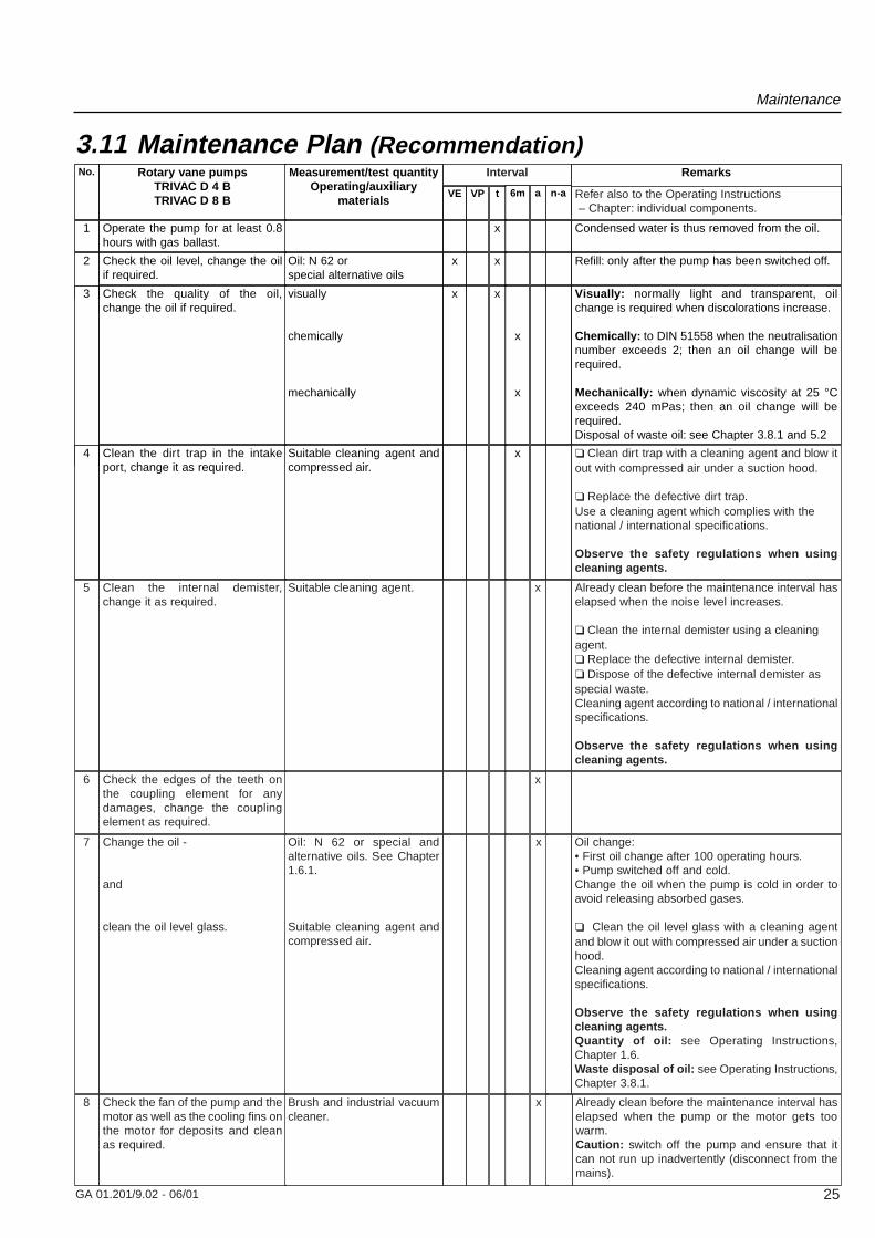
3.11 Maintenance Plan (Recommendation)No. Rotary vane pumps
TRIVAC D 4 BTRIVAC D 8 B
Measurement/test quantityOperating/auxiliary
materialsVE VP t 6m a n-a
Remarks
1 Operate the pump for at least 0.8hours with gas ballast.
x Condensed water is thus removed from the oil.
2 Check the oil level, change the oilif required.
Oil: N 62 or special alternative oils
x x Refill: only after the pump has been switched off.
3 Check the quality of the oil,change the oil if required.
visually
chemically
mechanically
x x
x
x
Visually: normally light and transparent, oilchange is required when discolorations increase.
Chemically: to DIN 51558 when the neutralisationnumber exceeds 2; then an oil change will berequired.
Mechanically: when dynamic viscosity at 25 °Cexceeds 240 mPas; then an oil change will berequired.Disposal of waste oil: see Chapter 3.8.1 and 5.2
4 Clean the dirt trap in the intakeport, change it as required.
Suitable cleaning agent andcompressed air.
x ❏ Clean dirt trap with a cleaning agent and blow itout with compressed air under a suction hood.
❏ Replace the defective dirt trap.Use a cleaning agent which complies with thenational / international specifications.
Observe the safety regulations when usingcleaning agents.
Interval
Refer also to the Operating Instructions– Chapter: individual components.
5 Clean the internal demister,change it as required.
Suitable cleaning agent. x Already clean before the maintenance interval haselapsed when the noise level increases.
❏ Clean the internal demister using a cleaningagent.❏ Replace the defective internal demister.❏ Dispose of the defective internal demister asspecial waste.Cleaning agent according to national / internationalspecifications.
Observe the safety regulations when usingcleaning agents.
6 Check the edges of the teeth onthe coupling element for anydamages, change the couplingelement as required.
x
7 Change the oil -
and
clean the oil level glass.
Oil: N 62 or special andalternative oils. See Chapter1.6.1.
Suitable cleaning agent andcompressed air.
8 Check the fan of the pump and themotor as well as the cooling fins onthe motor for deposits and cleanas required.
Brush and industrial vacuumcleaner.
x
x Already clean before the maintenance interval haselapsed when the pump or the motor gets toowarm.Caution: switch off the pump and ensure that itcan not run up inadvertently (disconnect from themains).
Oil change:• First oil change after 100 operating hours.• Pump switched off and cold.Change the oil when the pump is cold in order toavoid releasing absorbed gases.
❏ Clean the oil level glass with a cleaning agentand blow it out with compressed air under a suctionhood.Cleaning agent according to national / internationalspecifications.
Observe the safety regulations when usingcleaning agents.Quantity of oil: see Operating Instructions,Chapter 1.6.Waste disposal of oil: see Operating Instructions,Chapter 3.8.1.
GA 01.201/9.02 - 06/01 25
26 GA 01.201/9.02 - 06/01
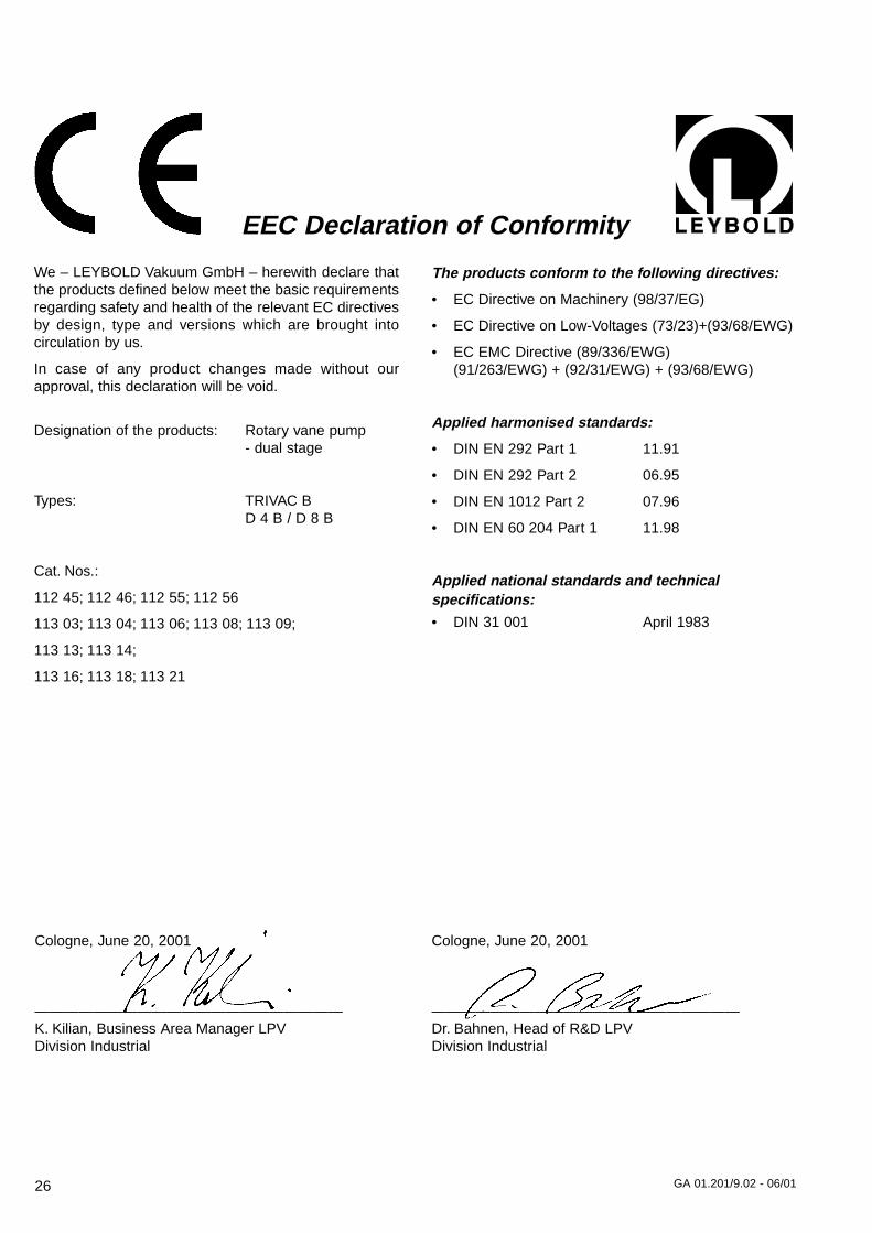
We – LEYBOLD Vakuum GmbH – herewith declare thatthe products defined below meet the basic requirementsregarding safety and health of the relevant EC directivesby design, type and versions which are brought into circulation by us.
In case of any product changes made without ourapproval, this declaration will be void.
Designation of the products: Rotary vane pump- dual stage
Types: TRIVAC B D 4 B / D 8 B
Cat. Nos.:
112 45; 112 46; 112 55; 112 56
113 03; 113 04; 113 06; 113 08; 113 09;
113 13; 113 14;
113 16; 113 18; 113 21
EEC Declaration of Conformity
The products conform to the following directives:
• EC Directive on Machinery (98/37/EG)
• EC Directive on Low-Voltages (73/23)+(93/68/EWG)
• EC EMC Directive (89/336/EWG)(91/263/EWG) + (92/31/EWG) + (93/68/EWG)
Applied harmonised standards:
• DIN EN 292 Part 1 11.91
• DIN EN 292 Part 2 06.95
• DIN EN 1012 Part 2 07.96
• DIN EN 60 204 Part 1 11.98
Applied national standards and technical specifications:
• DIN 31 001 April 1983
Cologne, June 20, 2001
—————————————————————K. Kilian, Business Area Manager LPVDivision Industrial
Cologne, June 20, 2001
—————————————————————Dr. Bahnen, Head of R&D LPV Division Industrial
27GA 01.201/9.02 - 06/01
We – Leybold Vacuum GmbH – herewith declare thatoperation of the incomplete machine defined below, isnot permissible until it has been determined that themachine into which this incomplete machine is to beinstalled, meets the regulations of the EEC Directive onMachinery.
Designation of the products: Rotary vane pump- dual stage
Types: TRIVAC B D 4 B without motor D 8 B without motor
Cat. Nos.: 113 07113 17
EEC Manufacturer’s Declarationin the sense of the Directive on Machinery 89/392/EWG, Annex IIb
Applied harmonised standards:
• DIN EN 292 Part 1 11.91
• DIN EN 292 Part 2 06.95
• DIN EN 1012 Part 2 07.96
• DIN EN 60 204 Part 111.98
Applied national standards and technicalspecifications:
• DIN 31 001 April 1983
• DIN ISO 1940 Dec. 1993
Cologne, June 20, 2001
—————————————————————K. Kilian, Business Area Manager LPVDivision Industrial
Cologne, June 20, 2001
—————————————————————Dr. Bahnen, Head of R&D LPV Division Industrial
28 GA 01.201/9.02 - 06/01

29
GA 01.201/9.02 - 06/01
LPV
_038
13_2
001
b
icom
/OF
06.0
1
Prin
ted
in G
erm
any
on c
hlor
ine-
free
ble
ache
d pa
per
LEYBOLD VACUUM GmbHBonner Strasse 498 (Bayenthal)D-50968 CologneTel.: +49(0)221 347-0Fax: +49(0)221 347-1250http://www.leyboldvac.dee-mail:[email protected]
USA:LEYBOLD VACUUM USA5700 Mellon RoadExport, PA 15632Phone: +1-724-327 57 00Fax: +1-724-733 12 17Internet:http://www.leyboldvacuum.com
Canada:LEYBOLD Canada Inc.7050 Telford Way, Unit 5Mississauga, OntarioCanada L5S 1V7Phone: +1-905-672 77 04Fax: +1-905-672 22 49e-mail:[email protected]
AMERICA EUROPE ASIA
Deutschland:LEYBOLD VAKUUMGmbHBonner Straße 498D-50968 KölnPhone: +49-221-347-1234Fax: +49-221-347-12 45Internet: www.leyboldvac.dee-mail:[email protected]
Belgien/Niederlande/Luxemburg:LEYBOLD N.V.Leuvensesteenweg 542, 9AB-1930 ZaventemPhone: +32-2-71 10 083Fax: +32-2-72 08 338
LEYBOLD B.V.Computerweg 7NL-3606 AV MaarssenPhone: +31-346-583 999Fax: +31-346-583 990
Frankreich:LEYBOLD S.A.7, Avenue du QuebecZ.A. de Courtaboeuf, B.P. 42F-91942 Courtaboeuf CedexPhone: +33-1-69 82 48 00Fax: +33-1-69 07 57 38e-mail:Compuserve:100635,43
Groß-Britannien/Irland:LEYBOLD LTD.Waterside Way,Plough LaneGB-London SW 17 OHBPhone: +44-208-97170 00Fax: +44-208-97170 01
Italien:LEYBOLD S.P.A.Via Trasimeno 8I-20128 MilanoPhone: +39-02-27 22 31Fax: +39-02-27 20 96 41
Spanien:LEYBOLD S.A.C/. Mataró, 27Polígono Industrial LesGrasesE-08980 Sant Feliu deLlobregat (Barcelona)Phone: +34-93-666 46 16Fax: +34-93-666 43 70
Schweden:LEYBOLD ABBox 908440092 GöteborgPhone: +46-31-68 84 70Fax: +46-31-68 39 39
Schweiz/Liechtenstein:LEYBOLD AGLeutschenbachstraße 55CH-8050 ZürichPhone: +41-1-308 40 50Fax: +41-1-302 43 73
Volksrepublik China:LEYBOLD (Tianjin) VACUUM EQUIPMENT MANUFACTURING Co.,Ltd.Beichen EconomicDevelopment Area (BEDA)Tianjin 300400, ChinaPhone: +86-22 26 972 016Fax: +86-22 26 972 017e-mail:[email protected]
Japan:LEYBOLD Co., Ltd.Head Office Tobu A.K. Bldg. 4th Floor23-3, Shin-Yokohama 3-chome Kohoku-ku,Yokohama-shiKanagawa ken 222-0033 Phone: +81-45-471 33 30Fax: +81-45-471 33 23
Korea:LEYBOLD Korea Ltd.4th Fl. Shinan Bldg., 173-1Jangchoog-dong 2ga,Choong-kuSeoul 100-392, KoreaC.P.O. Box 709
Phone: +82-2-227 11 567Fax: +82-2-227 11 568
Singapore:BALZERS and LEYBOLDSingapore Pte. Ltd.1 Tuas South Street 3Singapore 638043Phone: +65-865 18 65Fax: +65-862 22 95
Taiwan:LEYBOLD Taiwan, Ltd.2 F, No 416-1, Sec. 3Chung-Hsin Rd.Chu Tung, Hsinchu.Taiwan R.O.C: 310Phone: +886-3-583 39 88Fax: +886-3-583 39 99
Sales Net worldwide

![Lecture 8 HYDRAULIC PUMPS [CONTINUED] 1. 2. 1.7.1 ... · Unbalanced vane pump with pressure-compensated variable delivery. 2. Balanced vane pump. 1.7.1 Unbalanced Vane Pump with Fixed](https://img.pdfslide.us/doc/110x75/5e7b47f4f37b13248168840a/lecture-8-hydraulic-pumps-continued-1-2-171-unbalanced-vane-pump-with.jpg)