Embed Size (px)
Citation preview
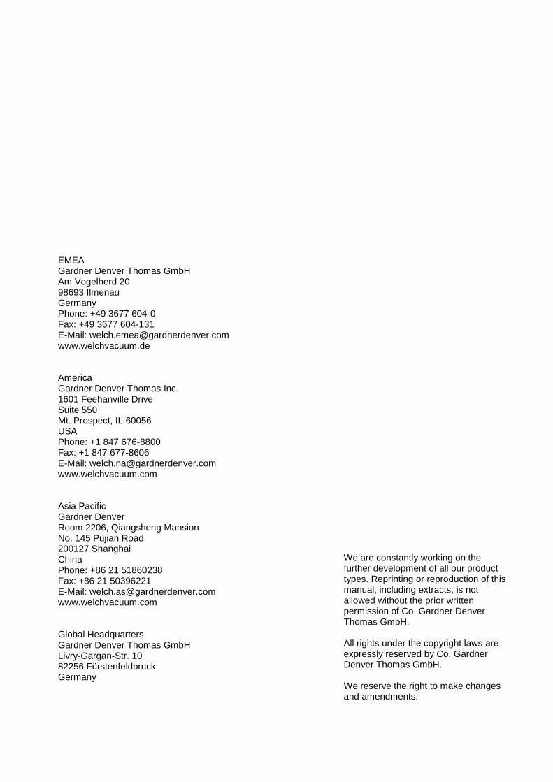
Operation Manual (EN) Original version of the operation manual
Rotary vane pumps Two-stage Series CRVpro CRVpro 48 CRVpro 65
P1700040 2020-06-12 P1700011 2020-06-12
EMEA Gardner Denver Thomas GmbH Am Vogelherd 20 98693 Ilmenau Germany Phone: +49 3677 604-0 Fax: +49 3677 604-131 E-Mail: [email protected] www.welchvacuum.de America Gardner Denver Thomas Inc. 1601 Feehanville Drive Suite 550 Mt. Prospect, IL 60056 USA Phone: +1 847 676-8800 Fax: +1 847 677-8606 E-Mail: [email protected] www.welchvacuum.com Asia Pacific Gardner Denver Room 2206, Qiangsheng Mansion No. 145 Pujian Road 200127 Shanghai China Phone: +86 21 51860238 Fax: +86 21 50396221 E-Mail: [email protected] www.welchvacuum.com Global Headquarters Gardner Denver Thomas GmbH Livry-Gargan-Str. 10 82256 Fürstenfeldbruck Germany
We are constantly working on the further development of all our product types. Reprinting or reproduction of this manual, including extracts, is not allowed without the prior written permission of Co. Gardner Denver Thomas GmbH. All rights under the copyright laws are expressly reserved by Co. Gardner Denver Thomas GmbH. We reserve the right to make changes and amendments.
Contents
P1700040 I
Contents
1 Important Information ....................................................................................................................... 1
1.1 Meaning of the Warning and Information notes ..................................................................... 1
1.2 General Information ................................................................................................................ 1
1.3 Target Groups ........................................................................................................................ 2
1.4 Intended Use .......................................................................................................................... 2
1.5 Use for an Unauthorized Purpose .......................................................................................... 2
1.6 Product Standards, Safety Regulations ................................................................................. 3
2 Basic Safety Instructions ................................................................................................................. 4
2.1 General Information ................................................................................................................ 4
2.2 Electricity ................................................................................................................................ 4
2.3 Mechanical Systems ............................................................................................................... 4
2.4 Hazardous Substances .......................................................................................................... 5
2.5 High Temperatures ................................................................................................................. 5
3 Description ......................................................................................................................................... 6
3.1 Design..................................................................................................................................... 6
3.2 Area of Application ................................................................................................................. 6
3.3 Scope of Delivery ................................................................................................................... 6
3.4 Function .................................................................................................................................. 8
3.4.1 Principles of Vacuum Pump Operation .................................................................................. 8
3.4.2 Working Principle of Rotary vane pumps ............................................................................... 8
3.4.3 Working Principle of Two-Stage Rotary vane pumps (CRVpro Series) ................................. 8
3.4.4 Oil Functions ......................................................................................................................... 10
3.4.5 Pump Lubrication .................................................................................................................. 10
3.4.6 Exhaust Filter ........................................................................................................................ 10
3.4.7 Gas Ballast ........................................................................................................................... 10
4 Technical Data ................................................................................................................................. 12
4.1 Dimensions ........................................................................................................................... 12
4.2 Pumping Speed / Intake Pressure – Diagram ...................................................................... 12
4.3 Device Data .......................................................................................................................... 13
4.4 Motor Data ............................................................................................................................ 13
4.5 Lubrication Data ................................................................................................................... 14
4.6 Order Numbers of Models .................................................................................................... 14
5 Installation and Operation .............................................................................................................. 15
5.1 Unpacking ............................................................................................................................. 15
5.2 Pump Mounting .................................................................................................................... 15
5.3 Pump Location / Environmental Conditions ......................................................................... 15
5.4 General References ............................................................................................................. 16
5.5 Installation and Connection .................................................................................................. 16
5.5.1 Connection to the Electric Service ....................................................................................... 17
5.5.2 Installation of the Grounding Plug ........................................................................................ 18
Contents
II P1700040
5.5.3 Change the Voltage Setting ................................................................................................. 19
5.5.4 Motor Protection................................................................................................................... 19
5.6 Starting-up ........................................................................................................................... 21
5.7 Operating Temperature ....................................................................................................... 21
5.8 Oil for Drawing off Oxygen ................................................................................................... 22
5.9 Gas Ballast Control .............................................................................................................. 22
5.10 Trap installation and maintenance ....................................................................................... 22
5.11 Side Panel Fitting Port ......................................................................................................... 23
5.12 Closing down ....................................................................................................................... 23
5.13 Storage ................................................................................................................................ 24
5.14 Transport .............................................................................................................................. 24
5.15 Scrap Disposal ..................................................................................................................... 24
6 Maintenance and Servicing ........................................................................................................... 25
6.1 Oil Level Control .................................................................................................................. 25
6.2 Oil Colour Check .................................................................................................................. 26
6.3 Oil Change ........................................................................................................................... 26
6.3.1 Draining the Oil .................................................................................................................... 26
6.3.2 Filling up with Oil .................................................................................................................. 27
6.3.3 Flushing ............................................................................................................................... 27
6.3.4 Frequency of Oil Changes ................................................................................................... 28
6.4 Shaft Seal Replacement ...................................................................................................... 28
6.5 Major Factory Repair ........................................................................................................... 28
7 Troubleshooting ............................................................................................................................. 29
8 Overview of Accessories ............................................................................................................... 31
8.1 Overview and Order Numbers for EMEA, Asia ................................................................... 31
8.2 Overview and Order Numbers for Americas ........................................................................ 31
8.3 32
8.4 Sorption trap ADT ................................................................................................................ 32
9 Overview of Spare Parts ................................................................................................................ 32
9.1 Fastening Kit ........................................................................................................................ 33
9.2 Seal Kit ................................................................................................................................. 34
9.3 Lip Seal Kit ........................................................................................................................... 34
9.4 Oil Drain Valve Kit ................................................................................................................ 35
9.5 Service Kit ............................................................................................................................ 35
9.6 Side Panel Fitting Kit ........................................................................................................... 36
9.7 List of Spare Parts ............................................................................................................... 37
10 Warranty .......................................................................................................................................... 41
11 EC Declaration ................................................................................................................................ 42
12 Global Contact ................................................................................................................................ 43
13 43
Important Information
P1700040 1
1 Important Information
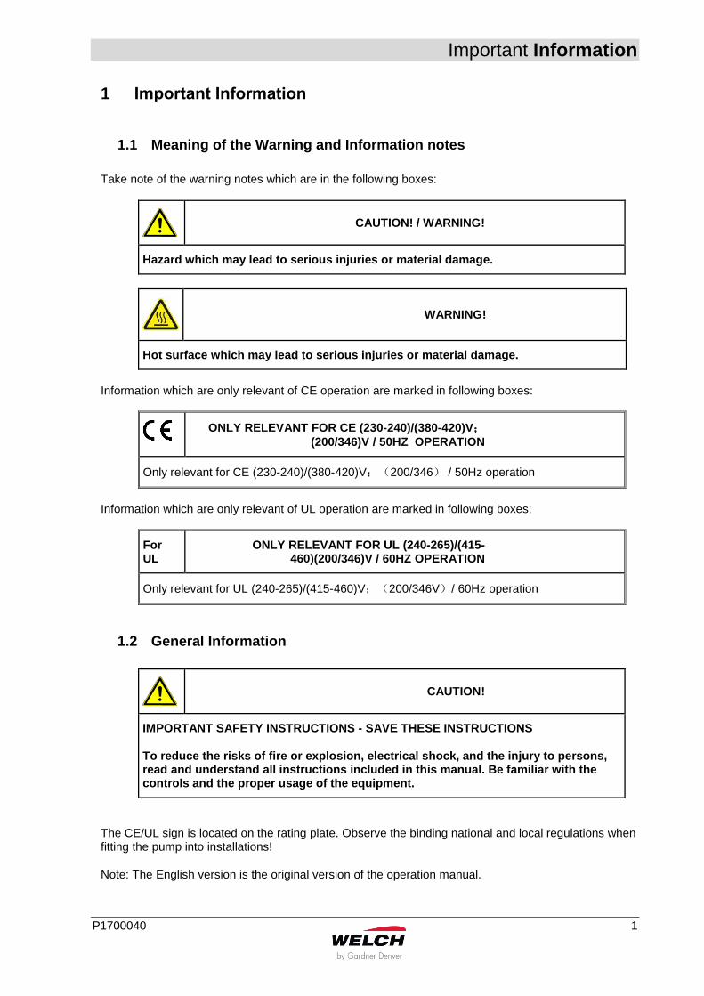
1.1 Meaning of the Warning and Information notes
Take note of the warning notes which are in the following boxes:
CAUTION! / WARNING!
Hazard which may lead to serious injuries or material damage.
WARNING!
Hot surface which may lead to serious injuries or material damage.
Information which are only relevant of CE operation are marked in following boxes:
ONLY RELEVANT FOR CE (230-240)/(380-420)V;
(200/346)V / 50HZ OPERATION
Only relevant for CE (230-240)/(380-420)V;(200/346) / 50Hz operation
Information which are only relevant of UL operation are marked in following boxes:
For UL
ONLY RELEVANT FOR UL (240-265)/(415-460)(200/346)V / 60HZ OPERATION
Only relevant for UL (240-265)/(415-460)V;(200/346V)/ 60Hz operation
1.2 General Information
CAUTION!
IMPORTANT SAFETY INSTRUCTIONS - SAVE THESE INSTRUCTIONS
To reduce the risks of fire or explosion, electrical shock, and the injury to persons, read and understand all instructions included in this manual. Be familiar with the controls and the proper usage of the equipment.
The CE/UL sign is located on the rating plate. Observe the binding national and local regulations when fitting the pump into installations!
Note: The English version is the original version of the operation manual.

Important Information
2 P1700040
Our products are sold worldwide and can therefore be equipped with the typical national plugs and for the various voltages.
ONLY RELEVANT FOR CE (230-240)/(380-420)V;
(200/346)V / 50HZ OPERATION
The rotary vane pump conforms to the following directives:
2006/42/EC Directive on machinery
2012/19/EU Directive on waste electrical and electronic equipment
2011/65/EU Directive on the restriction of the use of certain hazardous substances in electrical and electronic equipment
1.3 Target Groups
This operating manual is intended for the personnel planning, operating and maintaining standard, two-stage, Rotary vane pumps. This group of people includes:
Designers and fitters of vacuum apparatus
Employees working on commercial laboratory and industrial vacuum technology applications
Service personnel for Rotary vane pumps The personnel operating and maintaining the Rotary vane pumps must have the technical competence required to perform the work that has to be done and understand the hazards involved. The user must authorize the operating personnel to do the work that has to be done. The personnel must have read and understood the complete operating manual before using the Rotary vane pumps. The operating manual must be kept at the place of use and be available to the personnel when required.
1.4 Intended Use
The layout of the rotary vane pump must be appropriate for the conditions of use. The user bears the sole responsibility for this. The rotary vane pump may only be operated under the conditions stated:
in the “Technical Data” chapter
on the type plate and
in the technical specification for the order concerned
1.5 Use for an Unauthorized Purpose
It is forbidden to use the pump for applications deviating from the technical data stated on the type plate, in the operating manual or the conditions stated in the supply contract, or to operate it with missing or defective protective devices. The CRVpro standard pumps are not suited for pumping liquids.
Important Information
P1700040 3
1.6 Product Standards, Safety Regulations
ONLY RELEVANT FOR CE (230-240)/(380-420)V;
(200/346)V /50HZ OPERATION
The rotary vane pump meets the following product standards:
EN 60204-1 Safety of machinery - Electrical equipment of machines - Part 1: General requirements
Observe the standards and regulations applying in your country when you use the rotary vane pump.
Basic Safety Instructions
4 P1700040
2 Basic Safety Instructions IMPORTANT SAFETY INSTRUCTIONS SAVE THESE INSTRUCTIONS
2.1 General Information
CAUTION!
To reduce the risks of fire or explosion, electrical shock, and the injury to persons, read and understand all instructions included in this manual. Be familiar with the controls and the proper usage of the equipment
Warning notices must be observed. Disregarding them may lead to damage to health and property.
The Rotary vane pumps must be operated by personnel who can detect impending dangers and take action to prevent them from materializing.
The Rotary vane pumps is intended for indoor use only.
The manufacturer or authorized workshops will only service or maintain the rotary vane pump if it is accompanied by a fully completed damage report. Precise information about the contamination (also negative information if necessary) and thorough cleaning of the rotary vane pump are legally binding parts of the contract.
Contaminated Rotary vane pumps and their individual parts must be disposed of in accordance with the legal regulations. The local regulations apply in foreign countries.
2.2 Electricity
Please note the following when connecting to the electrical power supply system:
The electrical power supply system must have a protective connector according to IEC 60364-4-41 (for CE operation only).
CRVpro48+65 are supplied with PTC embedded three phase motor but without accessories for electrical connection. They must be connected via the appropriate cable and a suitable motor protection switch or PTC module to protect the motor from overheating in some emergency cases.
Set the switch in according with the rating on the motor nameplate.
After connecting the motor and after every time you alter the wiring, check the direction of rotation. To do so, briefly switch on the power and check whether a suitable cover (e.g. a blank flange) is sucked on at the intake port. If not, interchange two phases of the connection. Observe the direction arrow on the motor adapter.
The protective connector should not have any breaks.
The connecting cable should not be damaged.
2.3 Mechanical Systems
Improper use can lead to injuries or material damage. Observe the following instructions:
Only operate the Rotary vane pumps with the specified flange-mounting components.
Hazardous substances must be separated out as far as this is technically possible before they reach the pump.
Basic Safety Instructions
P1700040 5
External mechanical stresses and vibrations must not be transmitted to the pump. Only use flexible vacuum hoses for connecting Rotary vane pumps.
The pump should not be used to suck up fluids. Lay the exhaust pipe so that it slopes downwards, so allowing condensate to flow out of the pump. Collect the condensate and dispose of it in an environmentally compatible manner.
Maintain a space of least 20 cm between the pump and adjacent parts in order to enable the pump to cool.
CAUTION!
Solid particles in the pumping medium impair the pumping action and can lead to damage. Prevent solid particles penetrating into the pump!
2.4 Hazardous Substances
CAUTION!
The operating company bears the responsibility for the use of the rotary vane pump.
Hazardous substances in the gases to be pumped can cause personal injuries and property damage. Pay attention to the warning notices for handling hazardous substances. The local regulations apply in foreign countries. Combustible and explosive Gases Examine before switching on whether that can form gas combustible gas/air mixtures which can be promoted! Consider the regulations of the guideline 1999/92/EC. It is not permitted to pump gases that are combustible or prone to explosion. Aggressive gases The Rotary vane pumps are not certified according to ATEX directive 2014/34/EU.
Poisonous gases Use a separator when pumping poisonous or harmful gases. Prevent such substances from leaking out of the appliance or pump. Treat these substances according to the applicable environmental protection regulations. Test the strength and leak-tightness of the connecting lines and the connected apparatus. Prevent environmental poisons, e.g. mercury, getting into the Rotary vane pumps.
2.5 High Temperatures
The rotary vane pump may heat up as a result of the temperature of the gas being pumped and through intrinsic heating. In dependence on the operation mode, the casing temperature can reach 90 °C (motor). Prevent the following maximum permissible temperature from being exceeded.
+ 40 °C for the environment
The motor is protected against overload by a suitable protective device.
Description
6 P1700040
3 Description
3.1 Design
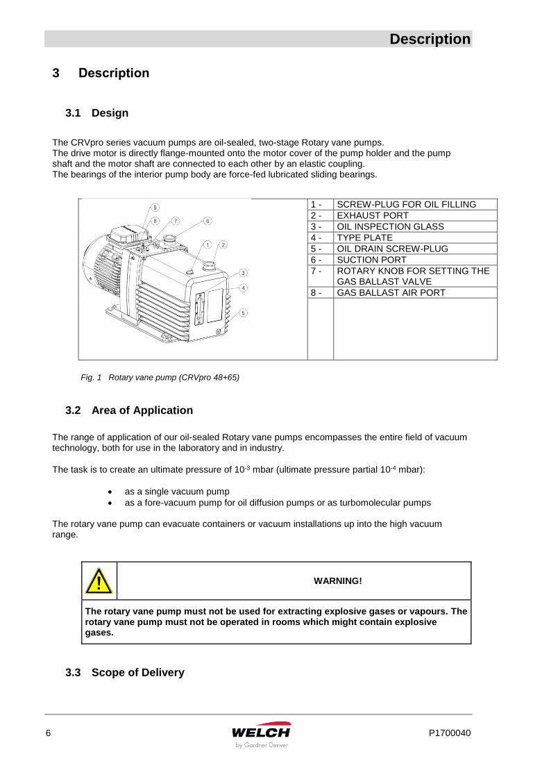
The CRVpro series vacuum pumps are oil-sealed, two-stage Rotary vane pumps. The drive motor is directly flange-mounted onto the motor cover of the pump holder and the pump shaft and the motor shaft are connected to each other by an elastic coupling. The bearings of the interior pump body are force-fed lubricated sliding bearings.
1 - SCREW-PLUG FOR OIL FILLING
2 - EXHAUST PORT
3 - OIL INSPECTION GLASS
4 - TYPE PLATE
5 - OIL DRAIN SCREW-PLUG
6 - SUCTION PORT
7 - ROTARY KNOB FOR SETTING THE GAS BALLAST VALVE
8 - GAS BALLAST AIR PORT
Fig. 1 Rotary vane pump (CRVpro 48+65)
3.2 Area of Application
The range of application of our oil-sealed Rotary vane pumps encompasses the entire field of vacuum technology, both for use in the laboratory and in industry.
The task is to create an ultimate pressure of 10-3 mbar (ultimate pressure partial 10-4 mbar):
as a single vacuum pump
as a fore-vacuum pump for oil diffusion pumps or as turbomolecular pumps The rotary vane pump can evacuate containers or vacuum installations up into the high vacuum range.
WARNING!
The rotary vane pump must not be used for extracting explosive gases or vapours. The rotary vane pump must not be operated in rooms which might contain explosive gases.
3.3 Scope of Delivery
Description
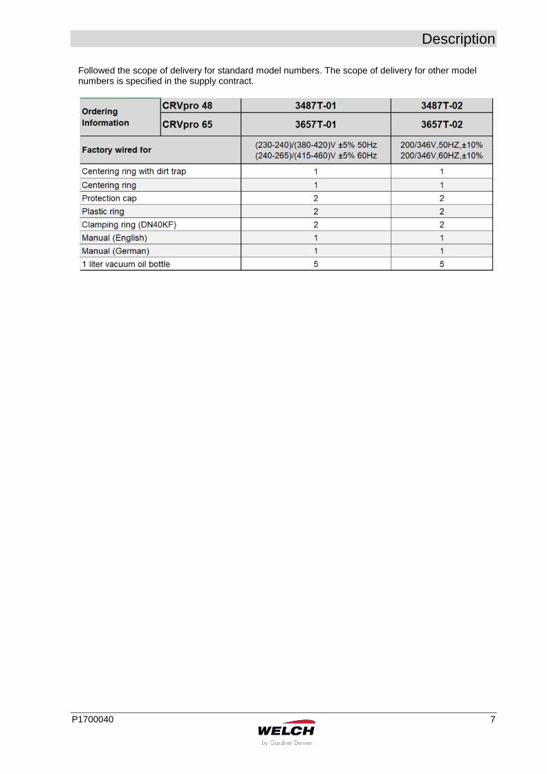
P1700040 7
Followed the scope of delivery for standard model numbers. The scope of delivery for other model numbers is specified in the supply contract.
Description
8 P1700040
3.4 Function
3.4.1 Principles of Vacuum Pump Operation
The main purpose of a vacuum pump is to reduce the pressure in a vessel or a closed system. The degree of pressure reduction is dependent upon the requirements of the application and the type of vacuum pump employed.
3.4.2 Working Principle of Rotary vane pumps
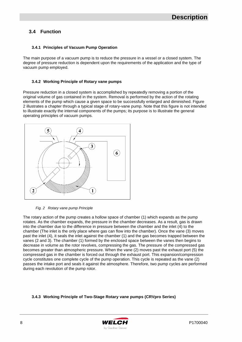
Pressure reduction in a closed system is accomplished by repeatedly removing a portion of the original volume of gas contained in the system. Removal is performed by the action of the rotating elements of the pump which cause a given space to be successfully enlarged and diminished. Figure 2 illustrates a chapter through a typical stage of rotary-vane pump. Note that this figure is not intended to illustrate exactly the internal components of the pumps; its purpose is to illustrate the general operating principles of vacuum pumps.
Fig. 2 Rotary vane pump Principle
The rotary action of the pump creates a hollow space of chamber (1) which expands as the pump rotates. As the chamber expands, the pressure in the chamber decreases. As a result, gas is drawn into the chamber due to the difference in pressure between the chamber and the inlet (4) to the chamber (The inlet is the only place where gas can flow into the chamber). Once the vane (3) moves past the inlet (4), it seals the inlet against the chamber (1) and the gas becomes trapped between the vanes (2 and 3). The chamber (1) formed by the enclosed space between the vanes then begins to decrease in volume as the rotor revolves, compressing the gas. The pressure of the compressed gas becomes greater than atmospheric pressure. When the vane (2) moves past the exhaust port (5) the compressed gas in the chamber is forced out through the exhaust port. This expansion/compression cycle constitutes one complete cycle of the pump operation. This cycle is repeated as the vane (2) passes the intake port and seals it against the atmosphere. Therefore, two pump cycles are performed during each revolution of the pump rotor.
3.4.3 Working Principle of Two-Stage Rotary vane pumps (CRVpro Series)
Description
P1700040 9
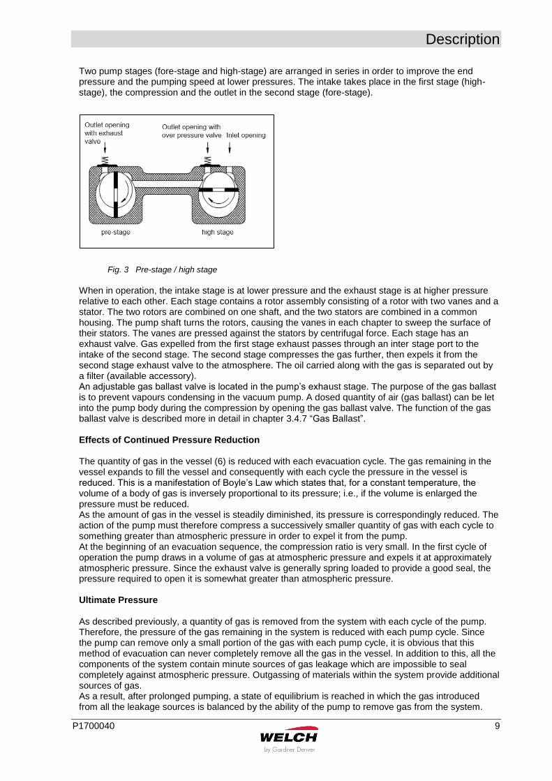
Two pump stages (fore-stage and high-stage) are arranged in series in order to improve the end pressure and the pumping speed at lower pressures. The intake takes place in the first stage (high-stage), the compression and the outlet in the second stage (fore-stage).
Fig. 3 Pre-stage / high stage
When in operation, the intake stage is at lower pressure and the exhaust stage is at higher pressure relative to each other. Each stage contains a rotor assembly consisting of a rotor with two vanes and a stator. The two rotors are combined on one shaft, and the two stators are combined in a common housing. The pump shaft turns the rotors, causing the vanes in each chapter to sweep the surface of their stators. The vanes are pressed against the stators by centrifugal force. Each stage has an exhaust valve. Gas expelled from the first stage exhaust passes through an inter stage port to the intake of the second stage. The second stage compresses the gas further, then expels it from the second stage exhaust valve to the atmosphere. The oil carried along with the gas is separated out by a filter (available accessory). An adjustable gas ballast valve is located in the pump’s exhaust stage. The purpose of the gas ballast is to prevent vapours condensing in the vacuum pump. A dosed quantity of air (gas ballast) can be let into the pump body during the compression by opening the gas ballast valve. The function of the gas ballast valve is described more in detail in chapter 3.4.7 “Gas Ballast”. Effects of Continued Pressure Reduction The quantity of gas in the vessel (6) is reduced with each evacuation cycle. The gas remaining in the vessel expands to fill the vessel and consequently with each cycle the pressure in the vessel is reduced. This is a manifestation of Boyle’s Law which states that, for a constant temperature, the volume of a body of gas is inversely proportional to its pressure; i.e., if the volume is enlarged the pressure must be reduced. As the amount of gas in the vessel is steadily diminished, its pressure is correspondingly reduced. The action of the pump must therefore compress a successively smaller quantity of gas with each cycle to something greater than atmospheric pressure in order to expel it from the pump. At the beginning of an evacuation sequence, the compression ratio is very small. In the first cycle of operation the pump draws in a volume of gas at atmospheric pressure and expels it at approximately atmospheric pressure. Since the exhaust valve is generally spring loaded to provide a good seal, the pressure required to open it is somewhat greater than atmospheric pressure. Ultimate Pressure As described previously, a quantity of gas is removed from the system with each cycle of the pump. Therefore, the pressure of the gas remaining in the system is reduced with each pump cycle. Since the pump can remove only a small portion of the gas with each pump cycle, it is obvious that this method of evacuation can never completely remove all the gas in the vessel. In addition to this, all the components of the system contain minute sources of gas leakage which are impossible to seal completely against atmospheric pressure. Outgassing of materials within the system provide additional sources of gas. As a result, after prolonged pumping, a state of equilibrium is reached in which the gas introduced from all the leakage sources is balanced by the ability of the pump to remove gas from the system.
Description
10 P1700040
This state of equilibrium is referred to as the ultimate pressure or blank off pressure of the pump and its system. No matter how much additional pumping time is provided, no further reduction in system pressure will be accomplished once ultimate pressure is attained. Intake Anti-suck back Protection When power to the pump is turned off, this device closes automatically, maintaining vacuum in the system being evacuated, and vents the inside of the pump to atmospheric pressure.
3.4.4 Oil Functions
WARNING!
Vacuum pump is shipped without oil inside to prevent possible spillage during shipment. Oil must be added prior to use!
The oil fulfils the following functions in the vacuum pump:
lubricating the sliding parts, such as rotor, vane, radial shaft seals
sealing the moving parts against the stator wall to reduce leaks
conducting the heat of compression to the metal walls (cooling) The oil transports the polluted particles and corrosive media and thus effects continuous cleaning of the internal surfaces.
3.4.5 Pump Lubrication
To ensure efficient operation and proper maintenance, and to minimize noise and oil vapours, it is important to use the correct type and quantity of oil. Directorr™ Premium vacuum oil has been especially developed to have the proper viscosity, low vapour pressure, and chemical stability needed to produce peak pumping efficiency. The ultimate vacuum guarantee on Welch pumps applies only when this oil is used. Each pump is supplied with sufficient oil for filling. Additional oil is available. See chapter 8 Overview of Accessories.
3.4.6 Exhaust Filter
Any oil-sealed vacuum pump tends to discharge oil mist from its exhaust port when the pump operates under high-flow conditions, such as when the pump’s intake is at or near atmospheric pressure. Typically, oil mist in the form of a white puff of “smoke” can be seen from the exhaust port when no filter is used. Once the vacuum level and the corresponding air flow through the pump are reduced, very little, if any, oil mist will be emitted. An exhaust filter is recommended for any vacuum pump installation where the pump operates at high intake pressures for a prolonged period of time. Oil droplets entrained in the pump’s exhaust are removed by the exhaust filter element. Use of an exhaust filter typically reduces or baffles pump noise as well. Exhaust filters are sometimes referred to as oil mist eliminators. See chapter 8 Overview of Accessories.
3.4.7 Gas Ballast
Condensates could have collected in the vacuum pump if:
the vacuum pump is new
it has not been used for long periods
the pump's maximum tolerance of water vapour pressure has been exceeded
Description
P1700040 11
When pumping condensable vapours, they may be compressed during the compression phase above the saturated vapour pressure and condense. This causes considerable deterioration in the vacuum pump’s performance:
ultimate pressure is not achieved
corrosion occurs
heavy oil contamination and formation of emulsions
CAUTION!
Operating with gas ballast increases the operating temperature of the vacuum pump by 5 – 10 K.
The gas ballast valve can increase the pump’s water vapour tolerance. In many vacuum pump applications the gases being pumped from a system are a combination of permanent gases and undesirable vapours such as water vapour. Under some conditions, the vapours condense in the second stage of the pump and contaminate the oil. The gas ballast valve reduces oil contamination by decreasing or eliminating vapour condensation. Vapour condensation is most likely to take place when the gas compression ratio is high, i.e. when the pump compresses a relatively large volume of gas to a small volume. Whether or not condensation takes place is dependent upon several factors, including the proportion of permanent gases to vapours at the pump intake. If the gases being pumped consist entirely of vapours, condensation will definitely occur unless the gas ballast valve is opened. The gas ballast valve adds a small amount of air at atmospheric pressure to the gas being compressed in the second stage. This reduces the compression required to push the gas out past the exhaust valve (less reduction in volume is required), and therefore reduces or eliminates condensation. When the gas ballast valve is open, the pump has to work a little harder, resulting in a slight increase in operating temperature. The increase in temperature is small, however, and is not harmful to the pump. Also, the pump is slightly noisier, and the pump’s ultimate pressure is somewhat reduced. Therefore, the gas ballast valve should be kept closed when it is not needed. Note that the gas ballast is not equally effective on all different types of chemical vapours, so it may not always eliminate condensation completely. Should condensate form despite actuation of the gas ballast device, the suction port must be closed and the pump operated with gas ballast for a lengthy period (about 2 hours).
Technical Data
12 P1700040
4 Technical Data
4.1 Dimensions
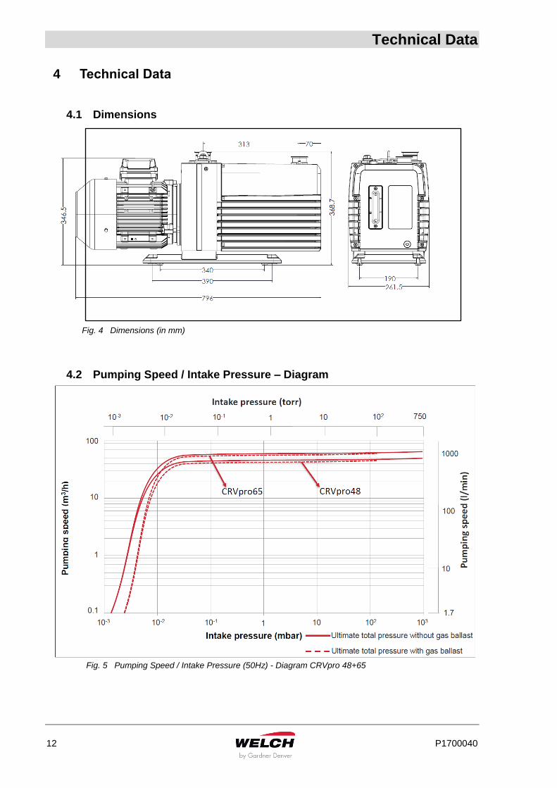
Fig. 4 Dimensions (in mm)
4.2 Pumping Speed / Intake Pressure – Diagram
Fig. 5 Pumping Speed / Intake Pressure (50Hz) - Diagram CRVpro 48+65

Technical Data
P1700040 13
4.3 Device Data
4.4 Motor Data
Parameter Unit 3487T-xx
CRVpro 48
3657T-xx
CRVpro 65
Free Air Displacement (max. pumping speed)
- @ 50Hz m3/h (L/min) 55.7 (928.3) 74.3 (1238.3)
- @ 60Hz CFM (L/min) 39.4 (1113.3) 52.5 (1486.7)
Pumping Speed
- @ 50Hz m3/h (L/min) 48.0(800) 65.0(1083.3)
- @ 60Hz CFM (L/min) 33.4(945) 44.8(1266.7)
Ultimate pressure (ISO21360)
- without gas ballast partial mbar (Torr) 3×10⁻⁴ (2×10⁻⁴) 3×10⁻⁴ (2×10⁻⁴)
- without gas ballast total mbar (Torr) 3×10⁻³ (2×10⁻³) 3×10⁻³ (2×10⁻³)
- with gas ballast total 1 mbar (Torr) 5×10⁻³ (4×10⁻³) 5×10⁻³ (4×10⁻³)
- with gas ballast total 2 mbar (Torr) 6×10⁻³ (5×10⁻³) 6×10⁻³ (5×10⁻³)
Max. inlet pressure bar 1 1
Max. outlet pressure bar 1.35 1.35
Connection flanges DN 40 KF 40 KF
Ambient temperature °C 10 - 40 10 - 40
Noise level (50Hz) dB (A) ≤58 ≤58
Noise level (60Hz) dB (A) ≤60 ≤60
Type of protection IP55 IP55
Oil filling l 4.9 4.3
Dimensions (W/D/H) mm (inch)
796x262x369
(31.4x10.3x14.5)
796x262x369
(31.4x10.3x14.5)
Shipping Carton Dimensions (W/D/H) mm (inch)
980x500x600
(38.6x19.7x23.6)
980x500x600
(38.6x19.7x23.6)
Weight kg (lbs.) 99 (218) 100 (220)
Shipping Weight kg (lbs.) 119 (262) 120 (264)
Parameter Unit
50 Hz 60 Hz
Frequency Hz
Frequency 50 Hz
Frequency 60 Hz (for UL)
Low Voltage V 230-240;200 240-265;200
High Voltage V 380-420;346 415-460;346
Motor power Kw 2.2 2.2
Nominal current (low voltage) A 7.86-7.55;9.04 7.30-6.62;8.76
Nominal current (high voltage) A 4.76-4.32;5.23 4.22-3.82;5.06
Motor speed 50/60Hz rpm 1460 1760
Technical Data
14 P1700040
4.5 Lubrication Data
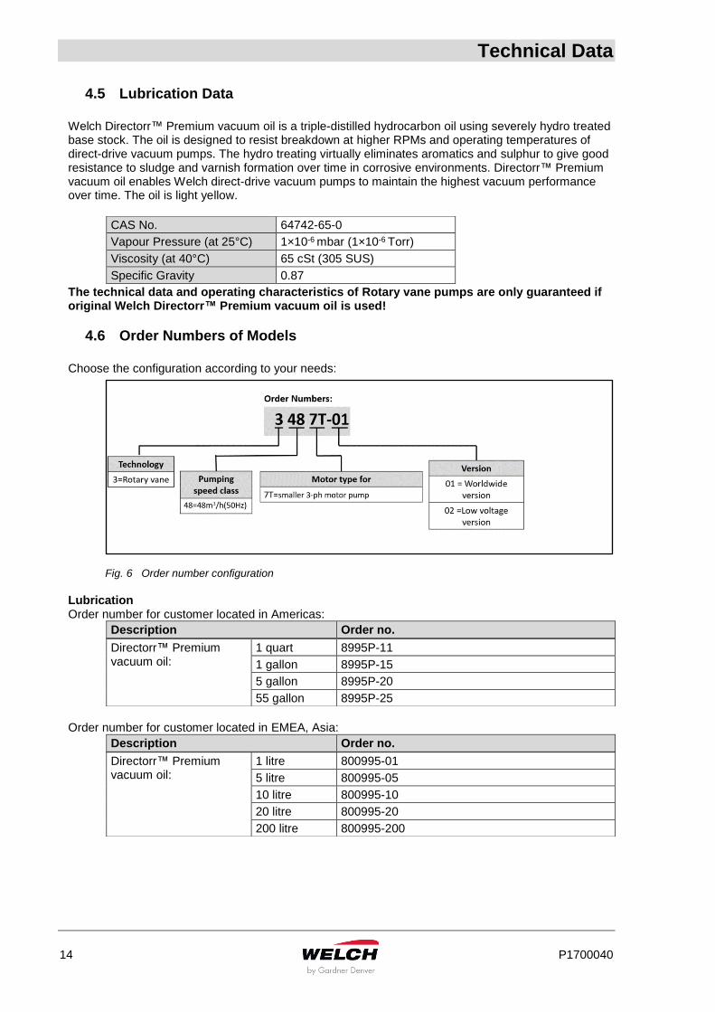
Welch Directorr™ Premium vacuum oil is a triple-distilled hydrocarbon oil using severely hydro treated base stock. The oil is designed to resist breakdown at higher RPMs and operating temperatures of direct-drive vacuum pumps. The hydro treating virtually eliminates aromatics and sulphur to give good resistance to sludge and varnish formation over time in corrosive environments. Directorr™ Premium vacuum oil enables Welch direct-drive vacuum pumps to maintain the highest vacuum performance over time. The oil is light yellow.
The technical data and operating characteristics of Rotary vane pumps are only guaranteed if original Welch Directorr™ Premium vacuum oil is used!
4.6 Order Numbers of Models
Choose the configuration according to your needs:
Fig. 6 Order number configuration
Lubrication Order number for customer located in Americas:
Description Order no.
Order number for customer located in EMEA, Asia:
Description Order no.
CAS No. 64742-65-0
Vapour Pressure (at 25°C) 1×10⁻⁶ mbar (1×10⁻⁶ Torr)
Viscosity (at 40°C) 65 cSt (305 SUS)
Specific Gravity 0.87
Directorr™ Premium vacuum oil:
1 quart 8995P-11
1 gallon 8995P-15
5 gallon 8995P-20
55 gallon 8995P-25
Directorr™ Premium vacuum oil:
1 litre 800995-01
5 litre 800995-05
10 litre 800995-10
20 litre 800995-20
200 litre 800995-200
Installation and Operation
P1700040 15
5 Installation and Operation
5.1 Unpacking
Carefully unpack the rotary vane pump. Keep all paperwork and inspection tags for future reference.
Check the pump for:
Transport damage
Conformity with the specifications of the supply contract (model, electrical supply data)
Completeness of the delivery
Please inform us without delay if there are discrepancies between the delivery and the contractually agreed scope of delivery, or if damage is detected. Please take note of the general terms of business of the manufacturing firm. In case of a claim under warranty, the device must be returned in packaging that is suitable for protecting it during transport.
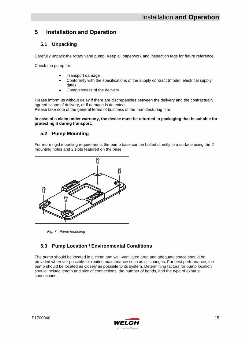
5.2 Pump Mounting
For more rigid mounting requirements the pump base can be bolted directly to a surface using the 2 mounting holes and 2 slots featured on the base.
Fig. 7 Pump mounting
5.3 Pump Location / Environmental Conditions
The pump should be located in a clean and well-ventilated area and adequate space should be provided wherever possible for routine maintenance such as oil changes. For best performance, the pump should be located as closely as possible to its system. Determining factors for pump location should include length and size of connections, the number of bends, and the type of exhaust connections.
Installation and Operation
16 P1700040
5.4 General References
CAUTION!
On continuous operation it’s recommended to run the pump below 10mbar maximum vacuum pressure.
According to its intended use the capacity of the vacuum pump depends on:
the kind of assembly
accessories
the oil used
additional connections
vacuum piping system
In addition, fail-safe operation is determined by the mode of maintenance. Elements such as valves, filters, condensers should be provided as early as in the conception. The materials of the vacuum piping should be selected in such a way that they will be resistant to the media to be delivered!
5.5 Installation and Connection
1. Set the rotary vane pump on a flat and horizontal surface. If more rigid mounting is required,
bolt the pump base to the surface. See chapter 5.2 Pump Mounting.
2. Remove the clamping ring and the protection cap of the suction and exhaust ports.
3. Attach the vacuum connection to the suction port and the exhaust pipe on the exhaust port. The suction and pressure ports must not be connected the wrong way round by mistake!
WARNING!
Never block or impede air flow from the exhaust port. High pressure can build up within the oil reservoir if the exhaust port is blocked. Check frequently, especially if exhaust is piped out of the building.
WARNING!
Consider the warning reference on the terminal box of the motor!
4. Recheck the oil level. If needed refill oil – see chapter 6.3.2 Filling up with Oil. Please note
that the pumps are delivered without oil filling. Initial oil filling must be done by the user.
5. Connect the rotary vane pump to the electrical supply. Please note the explanations on chapter 5.5.1 Connection to the Electric S.
6. How to operate the pump see chapter 5.6 Starting-up.
Installation and Operation
P1700040 17
5.5.1 Connection to the Electric Service
WARNING!
Should the user change the electrical connection, for example for fitting into a system, then this may only be performed by an electrical specialist under observance of the accident prevention regulations.
It is generally suggested to protect the motor by 120 per cent of is rated power in consideration of the starting and switch-on response.
Device connection cables and plugs must comply with the requirements of the line disconnection devices (current, output).
The customer/user shall install the main and emergency stop switches.
CRVpro48+65 are supplied with PTC embedded three phase motor but without accessories for electrical connection. They must be connected via the appropriate cable and a suitable motor protection switch or PTC module to protect the motor from overheating in some emergency cases.
Set the switch in according with the rating on the motor nameplate.
After connecting the motor and after every time you alter the wiring, check the direction of rotation. To do so, briefly switch on the power and check whether a suitable cover (e.g. a blank flange) is sucked on at the intake port. If not, interchange two phases of the connection. Observe the direction arrow on the motor adapter.

Installation and Operation
18 P1700040
5.5.2 Installation of the Grounding Plug
For UL
ONLY RELEVANT FOR UL ((240-265)/(415-460)V / (200/346)V 60HZ OPERATION
This product must be grounded. In the event of an electrical short circuit, grounding reduces the risk of electric shock by providing an escape wire for the electric current. User should equipped this product with a cord having a grounding wire with an appropriate grounding plug. The plug must be properly installed and grounded in accordance with all local codes and ordinances.
Check with a qualified electrician or serviceman when the grounding instructions are not completely understood, or when in doubt as to whether the product is properly grounded.
Do not use an adapter with this product. When the product must be reconnected for use on a different type of electric circuit, the reconnection shall be made by qualified service personnel.
Make sure your extension cord is not damaged. When using an extension cord, be sure to use one heavy enough to carry the current your product draws. An undersized cord results in a drop in line voltage and loss of power and overheating.
WARNING!
Improper installation of the grounding plug is able to result in a risk of electric shock. When repair or replacement of the cord or plug is required, do not connect the grounding wire to either flat blade terminal. The wire with insulation having an outer surface that is green with or without yellow stripes is the grounding wire.
Installation and Operation
P1700040 19
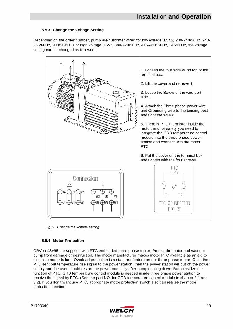
5.5.3 Change the Voltage Setting
Depending on the order number, pump are customer wired for low voltage (LV/△) 230-240/50Hz, 240-
265/60Hz, 200/50/60Hz or high voltage (HV/Y) 380-420/50Hz, 415-460/ 60Hz, 346/60Hz, the voltage
setting can be changed as followed:
1. Loosen the four screws on top of the terminal box.
2. Lift the cover and remove it. 3. Loose the Screw of the wire port side. 4. Attach the Three phase power wire and Grounding wire to the binding post and tight the screw. 5. There is PTC thermistor inside the motor, and for safety you need to integrate the GRB temperature control module into the three phase power station and connect with the motor PTC. 6. Put the cover on the terminal box and tighten with the four screws.
Fig. 9 Change the voltage setting
5.5.4 Motor Protection
CRVpro48+65 are supplied with PTC embedded three phase motor, Protect the motor and vacuum pump from damage or destruction. The motor manufacturer makes motor PTC available as an aid to minimize motor failure. Overload protection is a standard feature on our three-phase motor. Once the PTC sent out temperature rise signal to the power station, then the power station will cut off the power supply and the user should restart the power manually after pump cooling down. But to realize the function of PTC, GRB temperature control module is needed inside three phase power station to receive the signal by PTC. (See the part NO. for GRB temperature control module in chapter 8.1 and 8.2). If you don’t want use PTC, appropriate motor protection switch also can realize the motor protection function.
Installation and Operation
20 P1700040
CAUTION!
The motor has PTC inside, the user must integrate the GRB temperature control module into the three phase power station and connect with the motor PTC. Once the PTC sent out temperature rise signal to the power station, then the power station will cut off the power supply and the user should restart the power manually after pump cooling down. If you don’t want use PTC, appropriate motor protection switch also can realize the motor protection function.
Installation and Operation
P1700040 21
5.6 Starting-up
Observe the basic safety instructions when using the pump. Before using the pump for the first time, it is recommended to spend a few minutes inspecting the pump and its electrical and vacuum connections. Please notice the information which are listed in chapter 5 Installation and Operation.
1. Connect the power cord to the power outlet.
2. Recheck the oil level and add or remove oil as needed. How to do this see chapter 6.1 Oil Level Control.
3. Close off the pump intake and the gas ballast valve, and run the pump at blank off for a few minutes. The gurgling noise should go away after a few minutes of running; it is caused by the high volume of air that flows through the pump when the pump is first turned on. If the gurgling noise does not stop, check the oil level again to see if it is low. Also check the pump intake fitting to be sure that it is tight.
4. Once proper pump operation has been verified, the pump intake can be opened to the vacuum system.
5. After running the pump for a few minutes, check the oil level again. If the level is too high or too low, stop the pump, vent it to the atmosphere and add or remove oil as needed – see chapter 6.3 Oil Change.
6. Before starting the pump when connection to the vacuum system, check all vacuum connections.
CAUTION!
Check the oil level prior to switching on the vacuum pump!
5.7 Operating Temperature
The function of the vacuum pump filled with Directorr™ Premium vacuum oil is guaranteed between ambient temperatures of 10°C and 40°C. The lowest starting temperature is 10°C. The pump must be vented on the suction-side (suction port open).
WARNING!
In dependence on the operation mode, the casing temperature can reach 90°C. Make sure that the vacuum pump has not been installed in an accessible area, and make provision for a guard against contacts!
Installation and Operation
22 P1700040
5.8 Oil for Drawing off Oxygen
WARNING!
Pump should be not used for oxygen service! Oxygen at atmospheric pressure is exceptionally dangerous!
For drawing off oxygen containing mixtures or pure oxygen the following must be taken into consideration:
Mineral oils are flammable and not suitable for oxygen contents above 30%
The more they oxidise, the quicker they lose their properties. For this reason they only can be used up to an oxygen percentage of maximum 30 per cent in the medium to be delivered.
For higher oxygen contents synthetic oils have to be used, i.e., LABOVAC 13 (PFPE)
In order to prevent any accumulation of oxygen in the discharge space, neutral gas such as nitrogen may be let in through a special inlet assembly. The percentage of oxygen is being reduced. The added amount of gas should be 5 times as much as the percentage of oxygen. For pumping oxygen please order a CRVpro 65 specially prepared with PFPE oil (Order no. 3657T-01-03)
CAUTION! / WARNING!
There is a risk of explosion when pumping oxygen at a concentration above 30 percent.
5.9 Gas Ballast Control
The principle of the gas ballast is described in chapter 3.4.7 Gas Ballast. To open or close the gas ballast turn the gas ballast switch to the position open or close. Operation with gas ballast when drawing off condensable vapours We suggest operation with the gas ballast valve open, provided that the composition of gas in the vacuum pump to be drawn off is not known and cannot be ruled out. If condensable gas and vapours are to be delivered, the latter or their condensates will mix with the oil. As a result of this, the pump performance will degrade.
5.10 Trap installation and maintenance
Where corrosive vapours or large quantities of condensable vapours are evolved from vacuum processing, a cold trap may be used in the connecting line to the pump. It will help prevent damage to the pump mechanism and reduce oil contamination. The cold trap, immersed in a suitable Dewier flask, is installed so that the vapours may come in contact with the surfaces of the trap and condense. Commonly used refrigerants are liquid nitrogen or dry ice and acetone. The refrigerant to be used depends upon the freezing point of the contaminants. A variety of cold traps are available – see chapter 8 Accessories. When using a cold trap the refrigerant should be maintained at a high level in the flask to keep the trap at a uniformly low temperature. If the trap is rewarded it may allow re-evaporation of the condensate. The refrigerant add tube on the liquid nitrogen trap should not be obstructed as the refrigerant boil-off
Installation and Operation
P1700040 23
can produce dangerously high pressures. If the trap becomes saturated it should be disconnected from the system, drained and cleaned. An increase in pressure in the vacuum system will normally indicate that the trap has become saturated. To clean the trap, remove the trap from the system, allow the trap to warm up and rinse off the condensate with a suitable solvent in a fume hood. Thoroughly clean and dry the trap before reinstalling in the system.
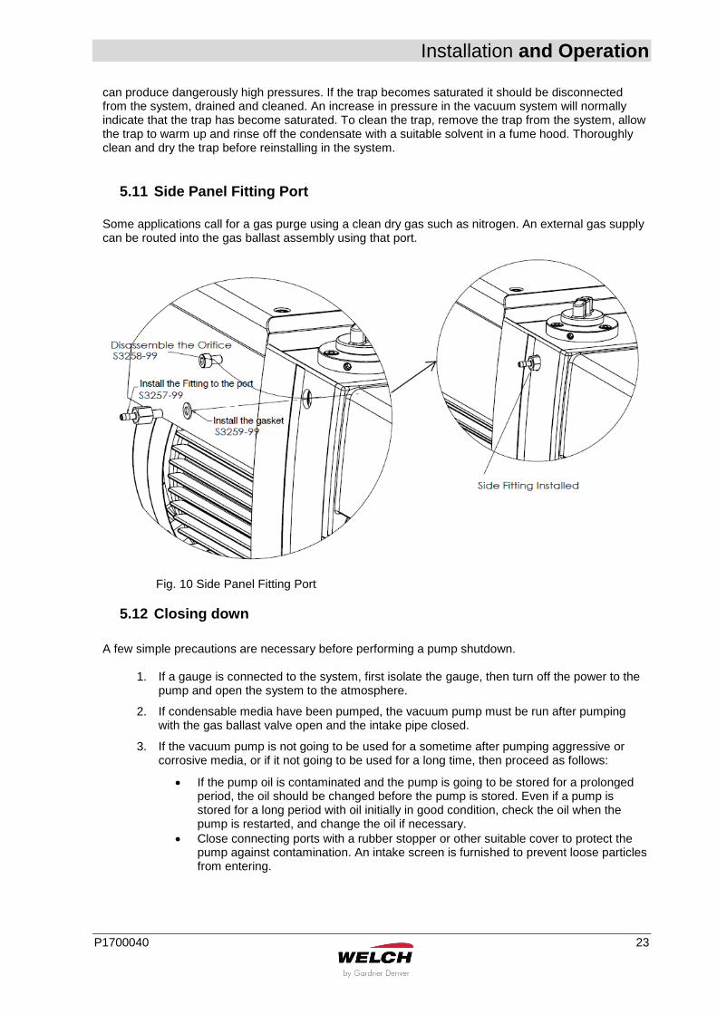
5.11 Side Panel Fitting Port
Some applications call for a gas purge using a clean dry gas such as nitrogen. An external gas supply can be routed into the gas ballast assembly using that port.
Fig. 10 Side Panel Fitting Port
5.12 Closing down
A few simple precautions are necessary before performing a pump shutdown.
1. If a gauge is connected to the system, first isolate the gauge, then turn off the power to the pump and open the system to the atmosphere.
2. If condensable media have been pumped, the vacuum pump must be run after pumping with the gas ballast valve open and the intake pipe closed.
3. If the vacuum pump is not going to be used for a sometime after pumping aggressive or corrosive media, or if it not going to be used for a long time, then proceed as follows:
If the pump oil is contaminated and the pump is going to be stored for a prolonged period, the oil should be changed before the pump is stored. Even if a pump is stored for a long period with oil initially in good condition, check the oil when the pump is restarted, and change the oil if necessary.
Close connecting ports with a rubber stopper or other suitable cover to protect the pump against contamination. An intake screen is furnished to prevent loose particles from entering.
Installation and Operation
24 P1700040
WARNING!
Take appropriate safety measures in case of having delivered dangerous media!
5.13 Storage
The pumps are to be stored in a low-dust, interior room within the temperature range from + 5 to + 40 °C and at a relative air humidity < 90%. Leave the protective elements on the suction and pressure ports. Another equally good protection may be used. If the pump oil is contaminated and the pump is going to be stored for a prolonged period, the oil should be changed before the pump is stored. Even if a pump is stored for a long period with oil initially in good condition, check the oil when the pump is restarted, and change the oil if necessary.
5.14 Transport
In case the pump has been filled with oil, please note that oil could flow into the cylinder which might break the vanes. Therefore it is highly recommended to drain all oil within the pump before transport. Instructions:
Use the Ring on the top side of the pump to lift the pump
Make sure to only transport the pump horizontally
Check for transport damage before initiating the pump
5.15 Scrap Disposal
CAUTION!
The Rotary vane pumps must be disposed of in accordance with the 2012/19/EU directive and the specific national regulations.
Contaminated Rotary vane pumps must be decontaminated according to the laws.
Maintenance and Servicing
P1700040 25
6 Maintenance and Servicing Under normal operating conditions the maintenance of the rotary vane pump is limited to:
external cleaning
checking running noises
checking the level and quality of the oil
regular oil changes
These maintenance intervals must be specified according to the prevailing operating conditions and adhered to. The bearings of the drive motors are life-long lubricated and so maintenance-free.
CAUTION!
Only perform the work that is described here, and that which is permitted to be done by the user. All other maintenance and service work may only be performed by the manufacturer or a dealer authorized by him.
Beware of the pump parts being possibly contaminated by hazardous substances. Wear protective clothing if there is contamination.
WARNING!
During repair or maintenance work which could endanger people because of moving or electrically live components, the vacuum pump must be made safe by removing the mains supply plug from the socket or by switching off the main contractor and preventing it from being switched on again!
6.1 Oil Level Control
CAUTION!
Check the oil level regularly!
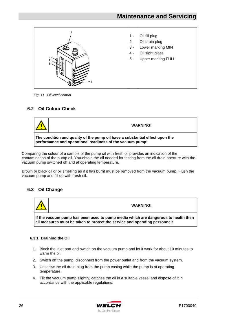
The oil consumption varies according to the vacuum pump’s operating conditions. In order to keep the vacuum pump at all times in an optimum operating condition, the oil level must be inspected at the oil sight glass. The oil level must at all times be showing between the upper and lower markings on the oil sight glass. The oil must be topped up if the oil level falls to the lower mark. We recommend to operate pump with oil filling at upper marking FULL. This minimize the service needs and allows better dilution of contaminants. When additional oil is required, use only Directorr™ Premium vacuum oil, pump performance is not guaranteed with other brands of oil.
Maintenance and Servicing
26 P1700040
1 - Oil fill plug
2 - Oil drain plug
3 - Lower marking MIN
4 - Oil sight glass
5 - Upper marking FULL
Fig. 11 Oil level control
6.2 Oil Colour Check
WARNING!
The condition and quality of the pump oil have a substantial effect upon the performance and operational readiness of the vacuum pump!
Comparing the colour of a sample of the pump oil with fresh oil provides an indication of the contamination of the pump oil. You obtain the oil needed for testing from the oil drain aperture with the vacuum pump switched off and at operating temperature. Brown or black oil or oil smelling as if it has burnt must be removed from the vacuum pump. Flush the vacuum pump and fill up with fresh oil.
6.3 Oil Change
WARNING!
If the vacuum pump has been used to pump media which are dangerous to health then all measures must be taken to protect the service and operating personnel!
6.3.1 Draining the Oil
1. Block the inlet port and switch on the vacuum pump and let it work for about 10 minutes to
warm the oil.
2. Switch off the pump, disconnect from the power outlet and from the vacuum system.
3. Unscrew the oil drain plug from the pump casing while the pump is at operating temperature.
4. Tilt the vacuum pump slightly, catches the oil in a suitable vessel and dispose of it in accordance with the applicable regulations.

Maintenance and Servicing
P1700040 27
WARNING!
Avoid skin contact with the oil! Dispose of the oil in accordance with the valid environmental protection regulations!
6.3.2 Filling up with Oil
1. Switch off the pump, disconnect from the power outlet and from the vacuum system.
2. Remove the oil fill plug.
3. Pour in the oil until it reaches the upper mark “FULL”.
4. Screw in the oil fill plug together with the seal once again.
5. Block the inlet port and switch on the vacuum pump and let it work for about 2 minutes.
6. Check the oil level when the pump is switched off, repeat if necessary.
WARNING!
Avoid skin contact with the oil! Wash hands thoroughly after handling. Keep out of reach of children. Dispose of the oil in accordance with the valid environmental protection regulations! Do not overfill, excess oil tends to be splashed out the pump exhaust! Use only Directorr™ Premium vacuum oil.
For best dilution of contaminants, especially on chemical applications, we recommend to keep always oil level at max.
6.3.3 Flushing
If the oil is heavily contaminated, the vacuum pump must be flushed, e.g.:
heavy clouding by condensates
suspended particles such as dust, fibres, abraded particles
dark coloration of the oil The flushing liquid should be the type of oil which is currently being used.
1. After the vacuum pump has been filled with fresh oil, allow it to warm up by running it with the suction port closed. If you have established that the old oil, which you have previously drained, was contaminated by condensate (e.g. water) then the gas ballast valve must be open.
2. Drain the flushing oil. If the oil still appears heavily contaminated, the flushing procedure must be repeated.
Maintenance and Servicing
28 P1700040
6.3.4 Frequency of Oil Changes
The oil change interval is completely dependent upon the running conditions of temperature, operating pressure, hours of daily operation, and upon the materials pumped. Clean, dry air at pressures below 0.7 mbar (50 mtorr) are the most forgiving conditions. To determine your own oil change interval, visually monitor the pump oil conditions at regular intervals. If you suspect harsh operating conditions, daily visual checks are recommended. When the oil becomes cloudy, dark or includes particles of solids, it is time to change the oil. Be sure to use only Directorr™ Premium vacuum oil. The ultimate pressure guarantee applies only if this oil is used!
6.4 Shaft Seal Replacement
When the shaft seal in the mounting plate shows signs of excessive oil leakage, it should be replaced. Before attempting replacement of the seal, the pump must be disconnected from the vacuum system and from the power outlet. A seal replacement kit is available. This kit contains the outer lip seal assembly and gasket, which can be replaced in the field. See chapter 10 “Overview of Spare Parts”.
6.5 Major Factory Repair
Repairs and maintenance going beyond the extent of the work described in the previous chapters or reconditioning or modification may only be performed by the manufacturer or authorized workshops. Drain the oil before dispatching the pump and dispose of the oil according to the regulations. The prerequisites for a handover are a complete and factually correct damage report, and a clean pump. Clean the pump aggregate and the pump casing after pumping media which are harmful to health and the environment. Fill up with sufficient oil to protect against corrosion during transport! For more detailed information please visit our webpage: https://www.welchvacuum.com/
If you should not have an entrance to the Internet, you can contact us via phone: Europe: +49 3677 604 0 Americas: +1 847 676 8800 Asia: +86 21 5186 0238
WARNING!
Incomplete or incorrectly completed damage reports may endanger the service personnel! Provide full information about contamination and clean the pump thoroughly before handing it over to third parties. The user shall be liable for the consequences of an incorrect damage report or a contaminated pump. The statements in the damage report are legally binding.
Troubleshooting
P1700040 29
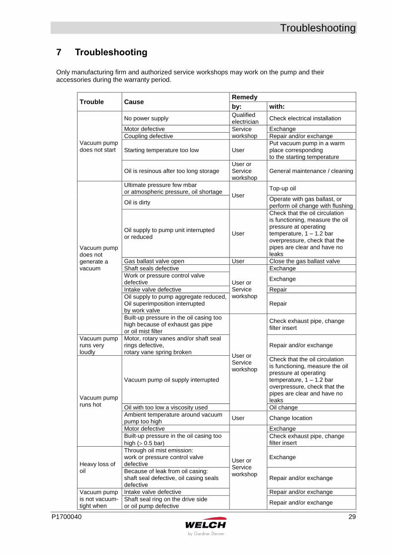
7 Troubleshooting Only manufacturing firm and authorized service workshops may work on the pump and their accessories during the warranty period.
Trouble Cause Remedy
by: with:
Vacuum pump does not start
No power supply Qualified electrician
Check electrical installation
Motor defective Service workshop
Exchange
Coupling defective Repair and/or exchange
Starting temperature too low User Put vacuum pump in a warm place corresponding to the starting temperature
Oil is resinous after too long storage User or Service workshop
General maintenance / cleaning
Vacuum pump does not generate a vacuum
Ultimate pressure few mbar or atmospheric pressure, oil shortage
User
Top-up oil
Oil is dirty Operate with gas ballast, or perform oil change with flushing
Oil supply to pump unit interrupted or reduced
User
Check that the oil circulation is functioning, measure the oil pressure at operating temperature, 1 – 1.2 bar overpressure, check that the pipes are clear and have no leaks
Gas ballast valve open User Close the gas ballast valve
Shaft seals defective
User or Service workshop
Exchange
Work or pressure control valve defective
Exchange
Intake valve defective Repair
Oil supply to pump aggregate reduced, Oil superimposition interrupted by work valve
Repair
Built-up pressure in the oil casing too high because of exhaust gas pipe or oil mist filter
User or Service workshop
Check exhaust pipe, change filter insert
Vacuum pump runs very loudly
Motor, rotary vanes and/or shaft seal rings defective, rotary vane spring broken
Repair and/or exchange
Vacuum pump runs hot
Vacuum pump oil supply interrupted
Check that the oil circulation is functioning, measure the oil pressure at operating temperature, 1 – 1.2 bar overpressure, check that the pipes are clear and have no leaks
Oil with too low a viscosity used Oil change
Ambient temperature around vacuum pump too high
User Change location
Motor defective
User or Service workshop
Exchange
Built-up pressure in the oil casing too
high ( 0.5 bar)
Check exhaust pipe, change filter insert
Heavy loss of oil
Through oil mist emission: work or pressure control valve defective
Exchange
Because of leak from oil casing: shaft seal defective, oil casing seals defective
Repair and/or exchange
Vacuum pump is not vacuum-tight when
Intake valve defective Repair and/or exchange
Shaft seal ring on the drive side or oil pump defective
Repair and/or exchange
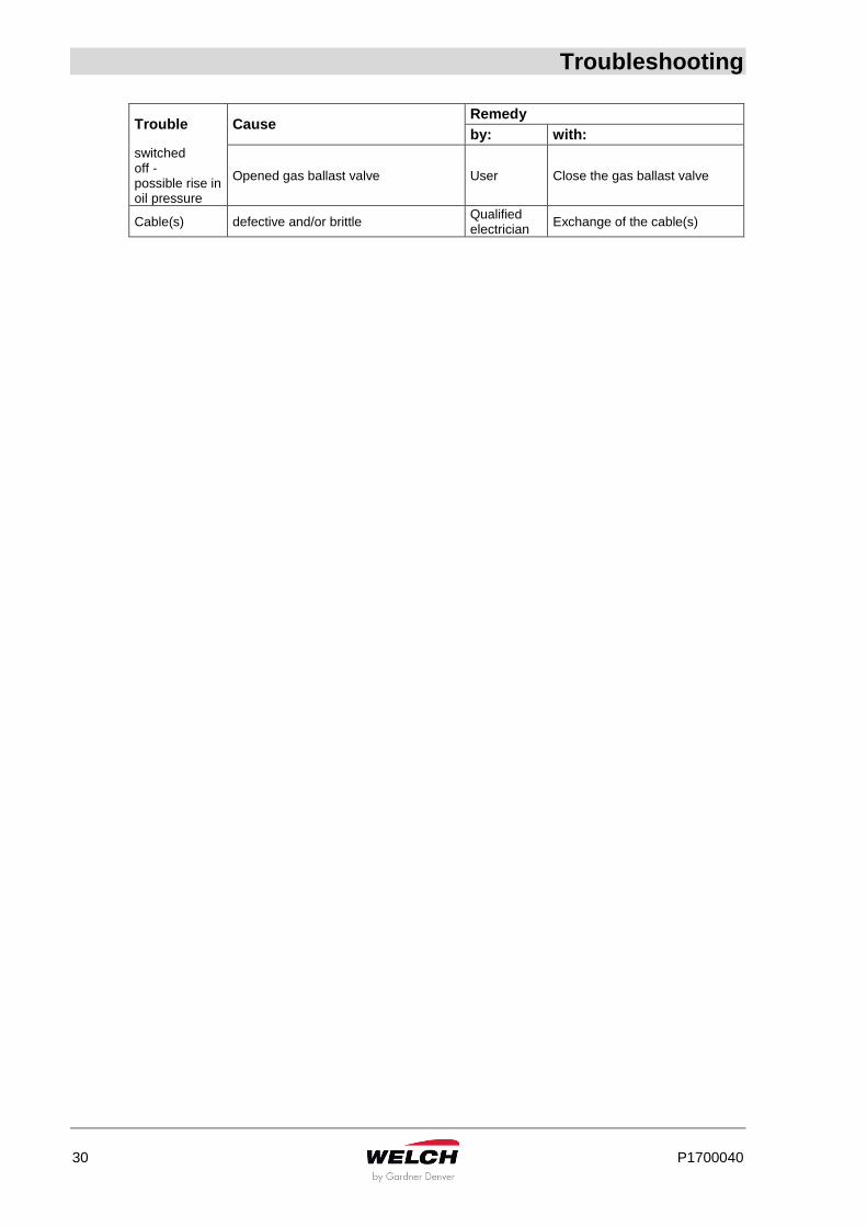
Troubleshooting
30 P1700040
Trouble Cause Remedy
by: with:
switched off - possible rise in oil pressure
Opened gas ballast valve User Close the gas ballast valve
Cable(s) defective and/or brittle Qualified electrician
Exchange of the cable(s)
Overview of Accessories
P1700040 31
8 Overview of Accessories
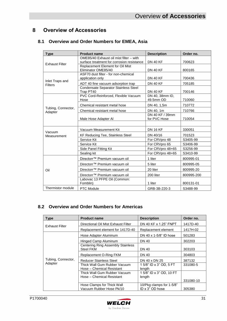
8.1 Overview and Order Numbers for EMEA, Asia
Type Product name Description Order no.
Exhaust Filter
OME85/40 Exhaust oil mist filter – with surface treatment for corrosion resistance DN 40 KF 700623
Replacement Element for Oil Mist Eliminator OME85/40 DN 40 KF 800165
Inlet Traps and Filters
ASF70 dust filter - for non-chemical application only DN 40 KF 700436
ADT 40 fine vacuum adsorption trap DN 40 KF 705185
Condensate Separator Stainless Steel Trap PT40 DN 40 KF 700146
Tubing, Connector, Adapter
PVC Cord-Reinforced, Flexible Vacuum Hose
DN 40, 38mm ID, 49.5mm OD 710060
Chemical resistant metal hose DN 40, 1,5m 710772
Chemical resistant metal hose DN 40, 1m 710766
Male Hose Adapter Al DN 40 KF / 39mm for PVC Hose 710054
Vacuum Measurement
Vacuum Measurement Kit DN 16 KF 330051
KF Reducing Tee, Stainless Steel DN 40/16 701523
Service Kit For CRVpro 48 S3405-99
Service Kit For CRVpro 65 S3406-99
Side Panel Fitting Kit For CRVpro 48+65 S3256-99
Sealing kit For CRVpro 48+65 S3410-99
Oil
Directorr™ Premium vacuum oil 1 liter 800995-01
Directorr™ Premium vacuum oil 5 liter 800995-05
Directorr™ Premium vacuum oil 20 liter 800995-20
Directorr™ Premium vacuum oil 200 liter 800995-200
Labovac 13 PFPE Oil (Common: Fomblin) 1 liter 800131-01
Thermistor module PTC Module GRB-3B-220-3 S3488-99
8.2 Overview and Order Numbers for Americas
Type Product name Description Order no.
Exhaust Filter Directional Oil Mist Exhaust Filter DN 40 KF x 1.25” FNPT 1417D-40
Replacement element for 1417D-40 Replacement element 1417H-02
Tubing, Connector, Adapter
Hose Adapter Aluminum DN 40 x 1-5/8” ID hose 501283
Hinged Camp Aluminum DN 40 302203
Centering Ring Assembly Stainless Steel FKM DN 40 303103
Replacement O-Ring FKM DN 40 304803
Reducer Stainless Steel DN 40 x DN 25 387132
Thick Wall Gum Rubber Vacuum Hose – Chemical Resistant
1 5/8” ID x 3” OD, 5 FT length
331080-5
Thick Wall Gum Rubber Vacuum Hose – Chemical Resistant
1 5/8” ID x 3” OD, 10 FT length 331080-10
Hose Clamps for Thick Wall Vacuum Rubber Hose Pk/10
10/Pkg clamps for 1-5/8” ID x 3” OD hose 305380
Overview of Spare Parts
32 P1700040
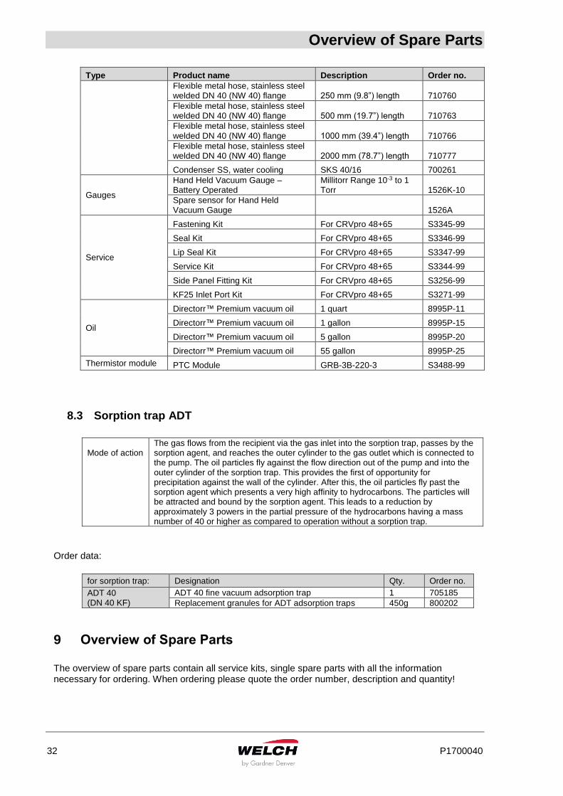
Type Product name Description Order no.
Flexible metal hose, stainless steel welded DN 40 (NW 40) flange 250 mm (9.8”) length 710760
Flexible metal hose, stainless steel welded DN 40 (NW 40) flange 500 mm (19.7”) length 710763
Flexible metal hose, stainless steel welded DN 40 (NW 40) flange 1000 mm (39.4”) length 710766
Flexible metal hose, stainless steel welded DN 40 (NW 40) flange 2000 mm (78.7”) length 710777
Condenser SS, water cooling SKS 40/16 700261
Gauges
Hand Held Vacuum Gauge – Battery Operated
Millitorr Range 10-3 to 1 Torr 1526K-10
Spare sensor for Hand Held Vacuum Gauge 1526A
Service
Fastening Kit For CRVpro 48+65 S3345-99
Seal Kit For CRVpro 48+65 S3346-99
Lip Seal Kit For CRVpro 48+65 S3347-99
Service Kit For CRVpro 48+65 S3344-99
Side Panel Fitting Kit For CRVpro 48+65 S3256-99
KF25 Inlet Port Kit For CRVpro 48+65 S3271-99
Oil
Directorr™ Premium vacuum oil 1 quart 8995P-11
Directorr™ Premium vacuum oil 1 gallon 8995P-15
Directorr™ Premium vacuum oil 5 gallon 8995P-20
Directorr™ Premium vacuum oil 55 gallon 8995P-25
Thermistor module PTC Module GRB-3B-220-3 S3488-99
8.3 Sorption trap ADT
Mode of action
The gas flows from the recipient via the gas inlet into the sorption trap, passes by the sorption agent, and reaches the outer cylinder to the gas outlet which is connected to the pump. The oil particles fly against the flow direction out of the pump and into the outer cylinder of the sorption trap. This provides the first of opportunity for precipitation against the wall of the cylinder. After this, the oil particles fly past the sorption agent which presents a very high affinity to hydrocarbons. The particles will be attracted and bound by the sorption agent. This leads to a reduction by approximately 3 powers in the partial pressure of the hydrocarbons having a mass number of 40 or higher as compared to operation without a sorption trap.
Order data:
for sorption trap: Designation Qty. Order no.
ADT 40 (DN 40 KF)
ADT 40 fine vacuum adsorption trap 1 705185
Replacement granules for ADT adsorption traps 450g 800202
9 Overview of Spare Parts The overview of spare parts contain all service kits, single spare parts with all the information necessary for ordering. When ordering please quote the order number, description and quantity!
Overview of Spare Parts
P1700040 33
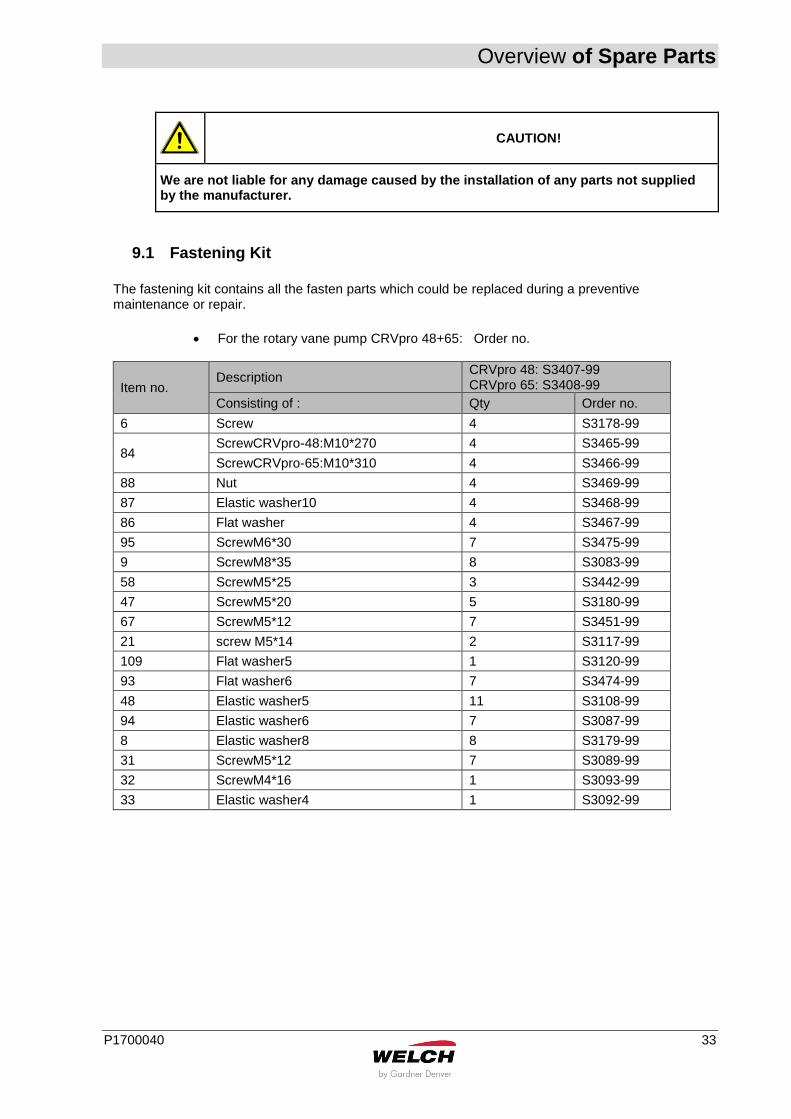
CAUTION!
We are not liable for any damage caused by the installation of any parts not supplied by the manufacturer.
9.1 Fastening Kit
The fastening kit contains all the fasten parts which could be replaced during a preventive maintenance or repair.
For the rotary vane pump CRVpro 48+65: Order no.
Item no. Description
CRVpro 48: S3407-99 CRVpro 65: S3408-99
Consisting of : Qty Order no.
6 Screw 4 S3178-99
84 ScrewCRVpro-48:M10*270 4 S3465-99
ScrewCRVpro-65:M10*310 4 S3466-99
88 Nut 4 S3469-99
87 Elastic washer10 4 S3468-99
86 Flat washer 4 S3467-99
95 ScrewM6*30 7 S3475-99
9 ScrewM8*35 8 S3083-99
58 ScrewM5*25 3 S3442-99
47 ScrewM5*20 5 S3180-99
67 ScrewM5*12 7 S3451-99
21 screw M5*14 2 S3117-99
109 Flat washer5 1 S3120-99
93 Flat washer6 7 S3474-99
48 Elastic washer5 11 S3108-99
94 Elastic washer6 7 S3087-99
8 Elastic washer8 8 S3179-99
31 ScrewM5*12 7 S3089-99
32 ScrewM4*16 1 S3093-99
33 Elastic washer4 1 S3092-99
Overview of Spare Parts
34 P1700040
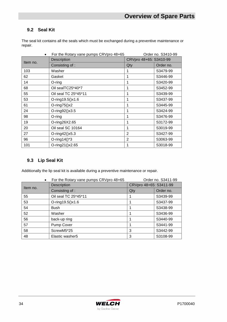
9.2 Seal Kit
The seal kit contains all the seals which must be exchanged during a preventive maintenance or repair.
For the Rotary vane pumps CRVpro 48+65 Order no. S3410-99
Item no. Description CRVpro 48+65: S3410-99
Consisting of : Qty Order no.
103 Washer 1 S3479-99
62 Gasket 1 S3446-99
14 O-ring 1 S3420-99
68 Oil sealTC25*40*7 1 S3452-99
55 Oil seal TC 25*45*11 1 S3439-99
53 O-ring19.5()x1.6 1 S3437-99
61 O-ring75()x2 1 S3445-99
24 O-ring92()x3.5 1 S3424-99
98 O-ring 1 S3476-99
19 O-ring26X2.65 1 S3172-99
20 Oil seal SC 10164 1 S3019-99
27 O-ring42()x5.3 2 S3427-99
96 O-ring14()*3 2 S3063-99
101 O-ring21()x2.65 1 S3018-99
9.3 Lip Seal Kit
Additionally the lip seal kit is available during a preventive maintenance or repair.
For the Rotary vane pumps CRVpro 48+65 Order no. S3411-99
Item no. Description CRVpro 48+65: S3411-99
Consisting of : Qty Order no.
55 Oil seal TC 25*45*11 1 S3439-99
53 O-ring19.5()x1.6 1 S3437-99
54 Bush 1 S3438-99
52 Washer 1 S3436-99
56 back-up ring 1 S3440-99
57 Pump Cover 1 S3441-99
58 ScrewM5*25 3 S3442-99
48 Elastic washer5 3 S3108-99
Overview of Spare Parts
P1700040 35
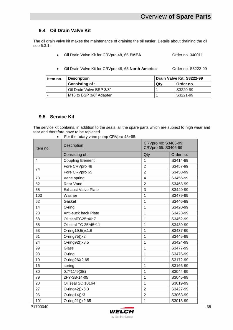
9.4 Oil Drain Valve Kit
The oil drain valve kit makes the maintenance of draining the oil easier. Details about draining the oil see 6.3.1.
Oil Drain Valve Kit for CRVpro 48, 65 EMEA Order no. 340011
Oil Drain Valve Kit for CRVpro 48, 65 North America Order no. S3222-99
Item no.
Description Drain Valve Kit: S3222-99
Consisting of : Qty. Order no.
9.5 Service Kit
The service kit contains, in addition to the seals, all the spare parts which are subject to high wear and tear and therefore have to be replaced.
For the rotary vane pump CRVpro 48+65:
Item no. Description
CRVpro 48: S3405-99; CRVpro 65: S3406-99
Consisting of : Qty Order no.
4 Coupling Element 1 S3414-99
74 Fore CRVpro 48 2 S3457-99
Fore CRVpro 65 2 S3458-99
73 Vane spring 4 S3456-99
82 Rear Vane 2 S3463-99
65 Exhaust Valve Plate 3 S3449-99
103 Washer 1 S3479-99
62 Gasket 1 S3446-99
14 O-ring 1 S3420-99
23 Anti-suck back Plate 1 S3423-99
68 Oil sealTC25*40*7 1 S3452-99
55 Oil seal TC 25*45*11 1 S3439-99
53 O-ring19.5()x1.6 1 S3437-99
61 O-ring75()x2 1 S3445-99
24 O-ring92()x3.5 1 S3424-99
99 Glass 1 S3477-99
98 O-ring 1 S3476-99
19 O-ring26X2.65 1 S3172-99
16 spring 1 S3166-99
80 0.7*11*9(3B) 1 S3044-99
79 2FY-3B-14-05 1 S3045-99
20 Oil seal SC 10164 1 S3019-99
27 O-ring42()x5.3 2 S3427-99
96 O-ring14()*3 2 S3063-99
101 O-ring21()x2.65 1 S3018-99
- Oil Drain Valve BSP 3/8” 1 S3220-99
- M16 to BSP 3/8” Adapter 1 S3221-99
Overview of Spare Parts
36 P1700040
108 Exhaust diaphragm 1 S3484-99
110 ScrewM5*10 1 S3485-99
106 nut 1 S3482-99
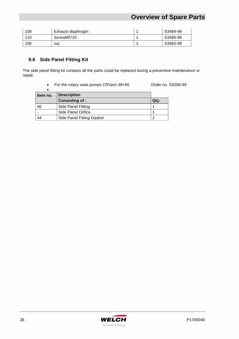
9.6 Side Panel Fitting Kit
The side panel fitting kit contains all the parts could be replaced during a preventive maintenance or repair.
For the rotary vane pumps CRVpro 48+65 Order no. S3256-99
Item no.
Description
Consisting of : Qty.
46 Side Panel Fitting 1
- Side Panel Orifice 1
44 Side Panel Fitting Gasket 2
Overview of Spare Parts
P1700040 37
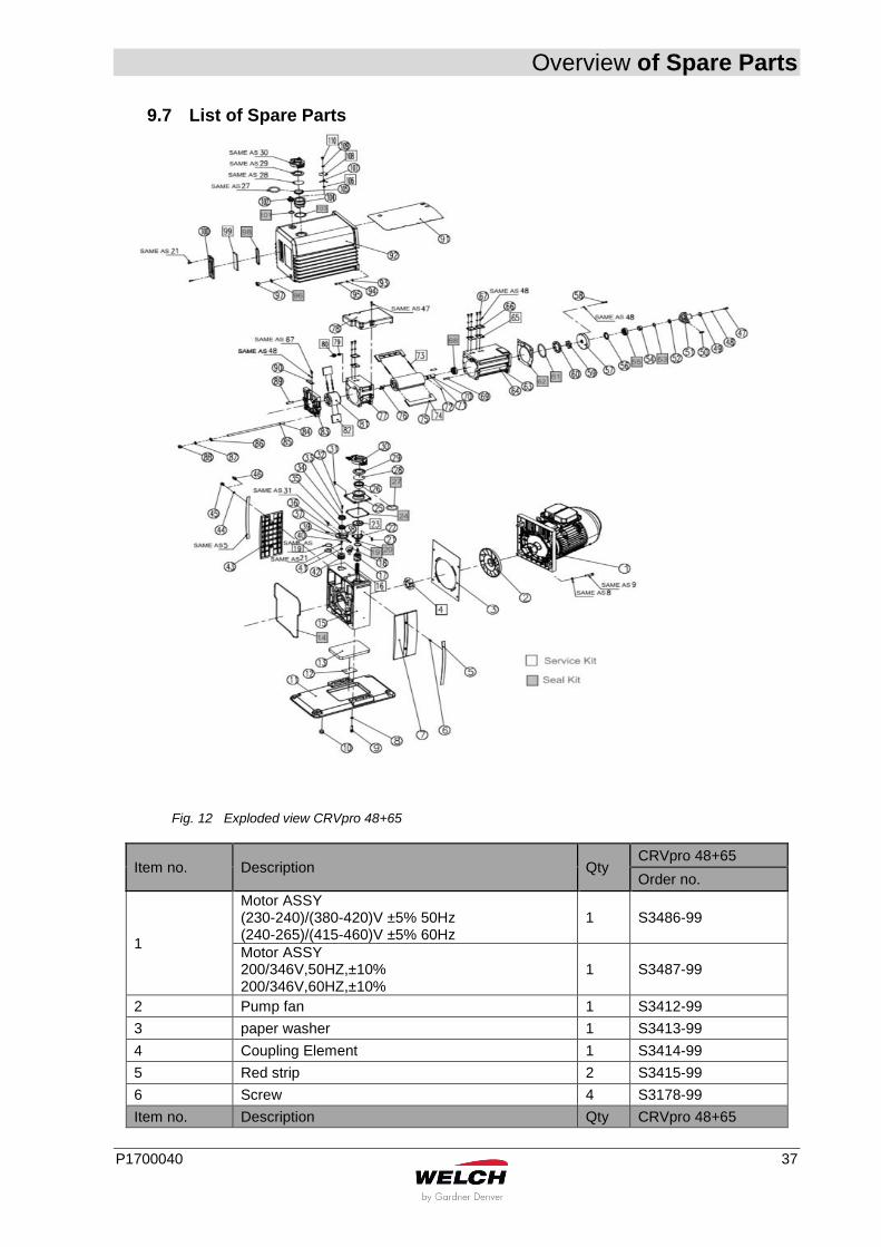
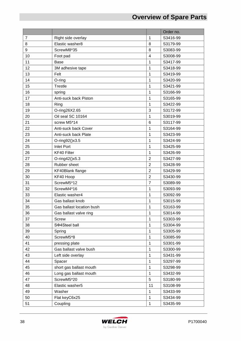
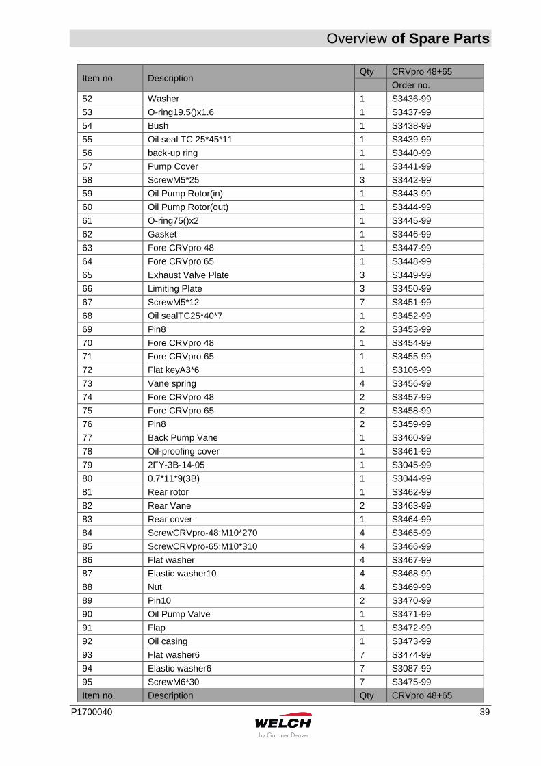
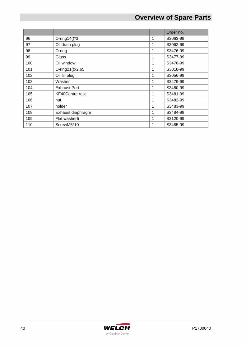
9.7 List of Spare Parts
Fig. 12 Exploded view CRVpro 48+65
Item no. Description Qty CRVpro 48+65
Order no.
1
Motor ASSY (230-240)/(380-420)V ±5% 50Hz (240-265)/(415-460)V ±5% 60Hz
1 S3486-99
Motor ASSY 200/346V,50HZ,±10% 200/346V,60HZ,±10%
1 S3487-99
2 Pump fan 1 S3412-99
3 paper washer 1 S3413-99
4 Coupling Element 1 S3414-99
5 Red strip 2 S3415-99
6 Screw 4 S3178-99
Item no. Description Qty CRVpro 48+65
Overview of Spare Parts
38 P1700040
Order no.
7 Right side overlay 1 S3416-99
8 Elastic washer8 8 S3179-99
9 ScrewM8*35 8 S3083-99
10 Foot pad 4 S3008-99
11 Base 1 S3417-99
12 3M adhesive tape 1 S3418-99
13 Felt 1 S3419-99
14 O-ring 1 S3420-99
15 Trestle 1 S3421-99
16 spring 1 S3166-99
17 Anti-suck back Piston 1 S3165-99
18 Ring 1 S3422-99
19 O-ring26X2.65 3 S3172-99
20 Oil seal SC 10164 1 S3019-99
21 screw M5*14 6 S3117-99
22 Anti-suck back Cover 1 S3164-99
23 Anti-suck back Plate 1 S3423-99
24 O-ring92()x3.5 1 S3424-99
25 Inlet Port 1 S3425-99
26 KF40 Filter 1 S3426-99
27 O-ring42()x5.3 2 S3427-99
28 Rubber sheet 2 S3428-99
29 KF40Blank flange 2 S3429-99
30 KF40 Hoop 2 S3430-99
31 ScrewM5*12 7 S3089-99
32 ScrewM4*16 1 S3093-99
33 Elastic washer4 1 S3092-99
34 Gas ballast knob 1 S3015-99
35 Gas ballast location bush 1 S3163-99
36 Gas ballast valve ring 1 S3014-99
37 Screw 1 S3303-99
38 SФ4Steel ball 1 S3304-99
39 Spring 1 S3305-99
40 ScrewM5*8 1 S3085-99
41 pressing plate 1 S3301-99
42 Gas ballast valve bush 1 S3300-99
43 Left side overlay 1 S3431-99
44 Spacer 1 S3297-99
45 short gas ballast mouth 1 S3298-99
46 Long gas ballast mouth 1 S3432-99
47 ScrewM5*20 5 S3180-99
48 Elastic washer5 11 S3108-99
49 Washer 1 S3433-99
50 Flat keyC6x25 1 S3434-99
51 Coupling 1 S3435-99
Overview of Spare Parts
P1700040 39
Item no. Description Qty CRVpro 48+65
Order no.
52 Washer 1 S3436-99
53 O-ring19.5()x1.6 1 S3437-99
54 Bush 1 S3438-99
55 Oil seal TC 25*45*11 1 S3439-99
56 back-up ring 1 S3440-99
57 Pump Cover 1 S3441-99
58 ScrewM5*25 3 S3442-99
59 Oil Pump Rotor(in) 1 S3443-99
60 Oil Pump Rotor(out) 1 S3444-99
61 O-ring75()x2 1 S3445-99
62 Gasket 1 S3446-99
63 Fore CRVpro 48 1 S3447-99
64 Fore CRVpro 65 1 S3448-99
65 Exhaust Valve Plate 3 S3449-99
66 Limiting Plate 3 S3450-99
67 ScrewM5*12 7 S3451-99
68 Oil sealTC25*40*7 1 S3452-99
69 Pin8 2 S3453-99
70 Fore CRVpro 48 1 S3454-99
71 Fore CRVpro 65 1 S3455-99
72 Flat keyA3*6 1 S3106-99
73 Vane spring 4 S3456-99
74 Fore CRVpro 48 2 S3457-99
75 Fore CRVpro 65 2 S3458-99
76 Pin8 2 S3459-99
77 Back Pump Vane 1 S3460-99
78 Oil-proofing cover 1 S3461-99
79 2FY-3B-14-05 1 S3045-99
80 0.7*11*9(3B) 1 S3044-99
81 Rear rotor 1 S3462-99
82 Rear Vane 2 S3463-99
83 Rear cover 1 S3464-99
84 ScrewCRVpro-48:M10*270 4 S3465-99
85 ScrewCRVpro-65:M10*310 4 S3466-99
86 Flat washer 4 S3467-99
87 Elastic washer10 4 S3468-99
88 Nut 4 S3469-99
89 Pin10 2 S3470-99
90 Oil Pump Valve 1 S3471-99
91 Flap 1 S3472-99
92 Oil casing 1 S3473-99
93 Flat washer6 7 S3474-99
94 Elastic washer6 7 S3087-99
95 ScrewM6*30 7 S3475-99
Item no. Description Qty CRVpro 48+65
Overview of Spare Parts
40 P1700040
Order no.
96 O-ring14()*3 1 S3063-99
97 Oil drain plug 1 S3062-99
98 O-ring 1 S3476-99
99 Glass 1 S3477-99
100 Oil window 1 S3478-99
101 O-ring21()x2.65 1 S3018-99
102 Oil fill plug 1 S3056-99
103 Washer 1 S3479-99
104 Exhaust Port 1 S3480-99
105 KF40Centre rest 1 S3481-99
106 nut 1 S3482-99
107 holder 1 S3483-99
108 Exhaust diaphragm 1 S3484-99
109 Flat washer5 1 S3120-99
110 ScrewM5*10 1 S3485-99
Warranty
P1700040 41
10 Warranty This Welch product is warranted to be free from defects in material and workmanship. The liability of Gardner Denver Thomas, Inc. under this warranty is limited to servicing, adjusting, repairing or replacing any unit or component part which in the judgment of Gardner Denver Thomas, Inc. has not been misused, abused or altered in any way causing impaired performance or rendering it inoperative. No other warranties are expressed or implied. The method of executing this warranty: servicing, adjusting, repairing or replacing shall be at the discretion of Gardner Denver Thomas, Inc. Vacuum pumps that have been used for any period, however short, will be repaired under this warranty rather than replaced. The warranty is effective for one year from the date of original purchase when: • The warranty card has been completed and returned. • The product is returned to the factory or other designated service center, freight prepaid. • The product in our judgment is defective through no action or fault of the user. If the product has become defective through misuse, abuse, or alteration, repairs will be billed regardless of the age of the product. In this event, an estimate of the repair costs will be submitted and authorization of these charges will be required before the product is repaired and returned. To reduce additional charges and delays either within or outside of the warranty period, contact Welch for a return authorization number. Products without a return authorization number will be refused by our receiving department. Before shipping, properly pack the pump, insure it against loss or damage, and on the outside of the pump packaging and the packing slip write in the return authorization number. Pumps damaged due to improper packaging are the customer’s responsibility.
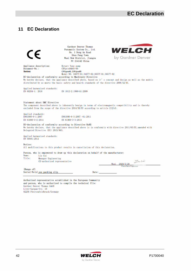
EC Declaration
42 P1700040
11 EC Declaration

Global Contact
P1700040 43
12 Global Contact EMEA Gardner Denver Thomas GmbH Am Vogelherd 20 98693 Ilmenau Germany Phone: +49 3677 604-0 Fax: +49 3677 604-131 E-Mail: [email protected] www.welchvacuum.de America Gardner Denver Thomas Inc. 1601 Feehanville Drive Suite 550 Mt. Prospect, IL 60056 USA Phone : +1 847 676-8800 Fax : +1 847 677-8606 E-Mail : [email protected] www.welchvacuum.com Asia Pacific Gardner Denver Room 2206, Qiangsheng Mansion No. 145 Pujian Road 200127 Shanghai China Phone: +86 21 51860238 Fax: +86 21 50396221 E-Mail: [email protected] www.welchvacuum.com Global Headquarters Gardner Denver Thomas GmbH Livry-Gargan-Str. 10 82256 Fürstenfeldbruck Germany
Global Contact
44 P1700040
DON’T PRINT THE FOLLOWING PAGES. Changing log.
Date Version Changing description Change Owner