Embed Size (px)
Citation preview

ROTARY TILLEROPERATOR MANUAL
Part No 999995 www.kingkutter.com
2150Eastern Ave.Gallipolis, Ohio 45631

2

3
TO THE PURCHASER
This manual contains valuable information about yournew King Kutter II Rotary Tiller. It has been carefully pre-pared to give you helpful suggestions for operating, adjust-ing, servicing and ordering repair parts.
Keep this manual in a convenient place for quick andeasy reference. Study it carefully. You have purchased adependable and sturdy tiller, but only by proper care andoperation can you expect to receive the service and long lifedesigned and built into it.
Sometime in the future your tiller may need new parts toreplace those that are worn or broken. If so, go to your dealerand provide him with the model and part number.
Customer Information
Name _______________________________________________
Purchased From ______________________________________
Date Purchased ______________________________________
Model No. ___________________________________________
Serial No. ___________________________________________

4
It is the purchaser and/or operator’s responsibility to….
Read and understand the information contained inthis manual.
Operate, lubricate, assemble and maintain the equip-ment in accordance with all instructions and safetyprocedures in this manual.
Inspect the equipment and replace or repair any partsthat are damaged or worn which under continued op-eration would cause damage, wear to other parts, orcause a safety hazard.
Return the equipment or parts to the authorized KingKutter dealer, from where it was purchased, for ser-vice or replacement of defective parts that are coveredby warranty. (The King Kutter II Factory may inspectequipment or parts before warranty claims are hon-ored.)
Payment of all costs incurred by the dealer for travel-ing to or transporting the equipment for warrantyinspection and or claims.

5
CONTENTS
ITEM PAGE
Safety ......................................................................... 6
Assembly Instructions ................................................ 8
Before Putting Into Service ........................................ 8
Safety Training ......................................................... 11
Transportation Safety ............................................... 15
Attaching To Tractor ................................................. 16
Sizing PTO ............................................................... 18
Operating Instructions.............................................. 19
Maintenance ............................................................. 20
Maintenance Safety ................................................. 20
Safety Decal's And Locations................................... 22
Replacement Parts................................................... 28
PTO Shaft Parts ...................................................... .30
Gearbox Parts....................................................32
Warranty ................................................................... 36

6
SIGNAL WORDS:
The signal words DANGER, WARNING and CAUTION are used withthe safety messages in this manual and with each safety sign. Theyare defined as follows:
DANGER: Indicates an immediate hazardous situation that, if notavoided, could result in serious injury or death. This signal word is to belimited to the most extreme situations typically for machine componentsthat, for functional purposes, cannot be guarded.
WARNING: Indicates a potentially hazardous situation that, if notavoided, could result in serious injury or death, and includes hazardsthat are exposed when guards are removed. It may also be used to alertagainst unsafe practices.
CAUTION: Indicates a potentially hazardous situation that, if not avoided,may result in minor or moderate injury. It may also be used to alertagainst unsafe practice.
If you have any questions not answered in this manual or require additionalcopies or the manual is damaged, please contact your local dealer or US&CSales P.O. Box 1200 Winfield, AL 35594 (205) 487-3202 orwww.kingkutter.com
READ AND FOLLOW THE INSTRUC-TIONS IN THIS MANUAL AND ESPE-CIALLY IN THE SAFETY SECTION.FAILURE TO DO SO CAN RESULT INSERIOUS INJURY OR DEATH.
TAKE NOTE! THIS SAFETY ALERTSYMBOL FOUND THROUGHOUTTHIS MANUAL IS USED TO CALLYOUR ATTENTION TO INSTRUC-TIONS INVOLVING YOUR PERSONALSAFETY AND THE SAFETY OF OTH-ERS.
SAFETY
THIS SYMBOL MEANSATTENTION!
BECOME ALERT!YOUR SAFTEY IS INVOLVED

7
EQUIPMENT SAFETY GUIDELINES
Safety of the operator and bystanders is one of the main concerns in designing anddeveloping a tiller. However, every year accidents occur which could have been avoidedby a few seconds of thought and a more careful approach to handling equipment. You,the operator, can avoid many accidents by observing the following precautions and insistthose working with you, or for you, follow them.
In order to provide a better view, certain photographs or illustrations in this manual mayshow an assembly with a safety shield removed. However, equipment should never beoperated in this condition. Keep all shields in place. If shield removal becomes neces-sary for repairs, replace the shield prior to use.
Replace any safety sign that is not readable or missing. Location of such safety signsare indicated in this manual.
Never use alcoholic beverages or drugs that can hinder alertness or coordination whileoperating this equipment. Consult your doctor about operating this machine while takingprescription medications.
Under no circumstances should children under the age of 18 be allowed to workwith this equipment. Do not allow persons to operate or assemble this unit untilthey have read this manual and have developed a thorough understanding ofthe safety precautions and how it works. Review the safety instructions with all usersannually.
This equipment is dangerous to children and persons unfamiliar with its operation. Theoperator should be a responsible, properly trained and physically able person familiarwith farm machinery and trained in this equipment’s operations. If the elderly are assist-ing with farm work, their physical limitations need to be recognized and accommodated.
Use a tractor equipped with a Roll Over Protective System and seat belts. (ROPS)
Never exceed the limits of a piece of machinery. If its ability to do a job, or to do so safely,is in question- DON’T TRY IT.
Do not modify the equipment in any way. Unauthorized modification could result in seri-ous injury or death and may impair the function and life of the equipment.
In addition to the design and the confirmation of this implement, including safety signsand safety equipment, hazard control and accident prevention are dependent upon theawareness, concern, prudence, and proper training of personnel involved in the opera-tion, transport, maintenance, and storage of the machine. Refer also to safety messagesand operation instruction in each of the appropriate sections of the tractor and tiller manuals.Pay close attention to the safety signs affixed to the tractor and the tiller.

8
ROTARY TILLER ASSEMBLY INSTRUCTIONS
STEP 1With rotary tiller still in crate, lay flat on a level surface. Cut banding straps on the two (2) upright crateposts.
STEP 2Remove the top & upper side sections of the crate, leaving the rotary tiller resting on the bottom sec-tion.
STEP 3Remove tie wire holding the PTO shaft and set aside PTO.
STEP 4Attach tiller according to your tractors manual and using the instructions on pages 16 and 17.
STEP 5Install tail back plate chain.
STEP 6Install PTO shaft as outlined in the Attaching to Tractor Section, pg 16-19.
Note: The safety chains on the PTO shaft should be attatched to the tractorand tiller to prevent the plastic safety shield from rotating.
BEFORE PUTTING ROTARY TILLER INTO SERVICE
(IMPORTANT-INSTRUCTIONS PRIOR TO START UP)SHIPPED WITHOUT OIL IN GEAR BOXES AND WITHOUT GREASE INGREASE FITTINGS. UNIT MUST BE SERVICED BEFORE USING.
• Fill Gearbox using gear oil (type GL5-85W 140 or Triple ZeroGrease; which can be poured, and has "EP" i.e. "Extreme Pressure"additives.)
• For all Grease Fittings use TYPE/grade II tube grease.
STEP 1 Place rotary tiller so that the deck is secure and level.
STEP 2 Remove 1/2” Pipe Plug (Located at top of transmission gearbox). SeeFigure A.
STEP 3 Fill gearbox using gear oil until gearbox is approximately 1/2 full. SeeFigures B.

9
STEP 4 Replace and tighten the 1/2” pipe plug and clean away any excess oil.See Figure C.
STEP 5 Remove 1/2” Pipe Plug (Located at top of side gearbox, See Figure D)and the 1/8" check plug (Located in side of the side gearbox).
STEP 6 Fill side gearbox using gear oil until the oil begins to overflow from thecheckplug hole. See Figure E.
STEP 7 Replace and tighten the 1/2” vent plug and the 1/8" check plug. Cleanaway any excess oil. See Figure F.
STEP 8 Grease the grease fitting on the "out-board hub," the two (2) grease fittings onthe PTO universal joints, the two (2) grease fittings on the PTO safety shieldand the inner surface portion of the PTO shaft. See Figures G,H and I.
CAUTION:DO NOT over fill gearbox. This could cause damage to oil seals and cancause permanent damage to the gearbox. This issue will not be coveredunder warranty.
Figure A Figure B
Figure C
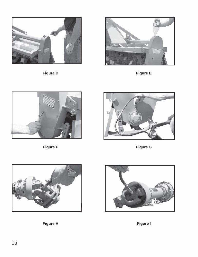
Figure D
Figure F
Figure H
10
Figure E
Figure G
Figure I

SAFETY TRAINING
Safety is a primary concern in the design and manufacturing of our prod-uct. Unfortunately, our efforts to provide safe equipment can be wipedout by a single careless act of an operator or bystander.
In addition to the design and configuration of equipment, hazard controland accident prevention are dependent upon the awareness, concern,prudence and proper training of personnel involved in the operation, trans-port, maintenance and storage of this equipment.
It has been said, “ The best safety device is an informed, careful opera-tor.” We ask you to be that kind of operator. It is the operator’s responsi-bility to read and understand all safety and operating instructions in themanual and to follow them. Accidents can be avoided.
Working with unfamiliar equipment can lead to careless injuries. Readthis manual, and the manual for your tractor, before assembly or operat-ing, to acquaint yourself with the machines. If this machine is used by anyperson other than you, or is loaned or rented, it is the rotary tiller owner’sresponsibility to make certain that the owner's manual be available to theoperator prior to operating:
1- Reads and understands the operator’s manuals.2- Is instructed in safe and proper use.
Know your controls and how to stop the tractor, engine, and tiller quicklyin an emergency. Read this manual and the one provided with your trac-tor.
Train all new personnel and review instructions frequently with existingworkers. Be certain only a properly trained and physically able person willoperate the machinery. A person who has not read and understood alloperating and safety instructions is not qualified to operate the machine.An untrained operator exposes himself and bystanders to possible seri-ous injury or death. If the elderly are assisting with farm work, their physi-cal limitations need to be recognized and accommodated.
11

PREPARATION
Never operate the tractor and tiller until you have read and completely understand this manual,the Tractor Operator’s Manual, and each of the safety messages found on the safety signs onthe tractor and tiller.Personal protection equipment including hardhat, safety glasses, safety shoes, and glovesare recommended during assembly, installation, operation, adjustment, maintenance, re-pairing, removal, or moving the implement. Do not allow long hair, loose fitting clothing, orjewelry to be around equipment.PROLONGED EXPOSURE TO LOUD NOISE MAY CAUSE PERMANENT HEARINGLOSS! Tractors with or without tillers attached can often be noisy enough to cause per-manent, partial hearing loss. We recommend that you wear hearing protection on a full-time basis if the noise in the operator’s position exceeds 80 db. Noise over 80 db on along-term basis can cause severe hearing loss. Noise over 90 db adjacent to the opera-tor over a long-term basis may cause permanent, total hearing loss. NOTE: Hearingloss from loud noise (from tractors, chain saws, radios, and other such sources close tothe ear) is cumulative over a lifetime without hope of natural recovery.Operate the tiller only with a tractor equipped with an approved Roll-Over-Protective Sys-tem (ROPS). Always wear your seat belt. Serious injury or even death could result fromfalling off the tractor — particularly during a turnover when the operator could be pinnedunder the ROPS or the tractor.Clear area to be tilled of stones, branches or other debris that might be thrown or en-tangled in the tiller, causing injury or damage.Operate only in daylight or good artificial light.Ensure tiller is properly mounted, adjusted and in good operating condition.Ensure that all safety shielding and safety signs are properly installed and in good condi-tion.
STARTING AND STOPPING SAFETY
Check the tractor master shield over the PTO stub shaft. Make sure it is in good condi-tion and fastened securely to the tractor. Purchase a new shield if old shield is damagedor missing.All tractors that are not equipped with a “live” power takeoff (PTO) need to be equippedwith an over-running PTO clutch. These are available through most farm equipment stores.NOTE: The addition of an over-running PTO clutch may change the length of the PTOdriveline required. Pay extra attention to the instructions on the PTO Driveline Installa-tion. Be sure that the driveline system guarding is adequate.Tiller operating power is supplied from the tractor PTO. Refer to your tractor manual forPTO engagement and disengagement instructions. Know how to stop tractor and tillerquickly in case of an emergency.When engaging PTO, the engine RPM should always be at idle speed. Once engagedand ready to start tilling, raise PTO speed to 540-RPM and maintain throughout tillingoperation.
12

13
OPERATIONAL SAFETY
The use of this equipment is subject to certain hazards that cannot beprotected against by the mechanical means or product design. All opera-tors of this equipment must read and understand this entire manual, pay-ing particular attention to safety and operating instructions, prior to using.If there is something in this manual you do not understand, ask your su-pervisor, or your dealer, to explain it to you.Most accidents occur because of neglect or carelessness. Keep all help-ers and bystanders at least several hundred feet from an operating rotarytiller. Only properly trained people should operate this machine.When machine is operated in populated areas where thrown objects couldinjure persons or property, operation must be stopped when anyonecomes within several hundred feet.The majority of the accidents involve entanglement on the driveline, injuryof bystanders by the objects thrown by the rotating tines, and operatorsbeing knocked off the tractor by low hanging limbs and then being runover by the tiller. Accidents are most likely to occur with machines thatare loaned or rented to someone who has not read the owner’s manualand is not familiar with a rotary tiller.The rotary tiller is designed for use only on tractors with the power take-off (PTO) turning at 540-RPM.Install and secure all guards and shields before starting or operating.The tiller tines, driveline guards and tractor, shields should be used andmaintained in good working condition. They should be inspected care-fully, at least daily, for missing or broken chain links, shields, or guards.(Worn items must be replaced at once to reduce possibility of injury.)Disengage power takeoff (PTO) and place transmission in neutral beforeattempting to start engine.Many varied objects, such as wire, cable, rope, or chains, can becomeentangled in the operating parts of the tiller. These items could then swingoutside the housing at greater velocities than the tines. Such a situationis extremely hazardous. Inspect the cutting area for such objects beforetilling. Remove any like objects from the site.

14
OPERATIONAL SAFETY continued...
Never allow the tilling tines to contact such items. Never assume an areais clear. Always Check!Always stop the tractor, disengage PTO, set brake, shut off the tractorengine, remove the ignition key, lower implement to the ground and allowrotating pieces to come to a complete stop before dismounting tractor.Never leave equipment unattended with the tractor running.Never place hands or feet under tiller with tractor engine running or be-fore you are sure all motion has stopped. Stay clear of all moving parts.Do not reach or place any part of your body under equipment until it isblocked securely.Do not allow riders on the rotary tiller or tractor at anytime. There is nosafe place for any riders.Do not operate unless all personnel, livestock, and pets are several hun-dred feet away to prevent injury by thrown objects.Never operate tractor and rotary tiller under trees with low hanging limbs.Operators can be knocked off the tractor and then run over by the rotatingtines.The rotating parts of this machine have been designed and tested forrugged use. However, they could fail upon impact with heavy, solid ob-jects such as steel guardrails and concrete abutment. Such impact couldcause the broken objects to be thrown outward at very high velocities. Toreduce the possibility of property damage, serious injury, or even death,never allow the tilling tines to contact such obstacles.Stop rotary tiller and tractor immediately upon striking an obstruction. Turnengine off, remove key, inspect and repair any damage before resumingoperation.Stay alert for uneven terrain, holes, rocks, and roots and other hiddenhazards. Keep away from drop-offs and hazards that could cause rollover. Use extreme care and maintain minimum ground speed when trans-porting or operating on hillsides, over rough ground and when operatingclose to ditches or fences. Be careful and slow down when turning sharpcorners and changing direction on slopes. Do not start or stop suddenlyon slopes. Avoid operation on steep slopes. In extremely uneven terrain,rear wheels weights, front tractor weight, and/or tire ballast should beused to improve stability.

OPERATIONAL SAFETY continued...
Pass rotary tiller diagonally through sharp dips and avoid sharp drops toprevent “hanging up” tractor and rotary tiller. Practice will improve yourskills in maneuvering on rough terrain. Always cut down slopes, neveracross the face. Always check tractor manual for proper use on slopes.When using a unit, a minimum 20% of tractor and equipment weight mustbe on tractor front wheels. Without this weight, tractor could tip over,causing personal injury or death. The weight may be attained with a front-end loader, front wheel weights, ballast in the tires or front tractor weights.When attaining a minimum 20% of tractor and equipment weight on thefront wheels, you must not exceed the ROPS weight certification. Weighthe tractor and equipment. Do not guess or estimate!
TRANSPORT SAFETY
Comply with state and local laws governing highway safety and move-ment of farm machinery on public roads.The use of flashing amber lights is acceptable in most localities. How-ever, some localities prohibit their use. Local laws should be checked forall lighting and marking requirements.At all times, when driving the tractor and equipment on the road or high-way under 20mph (32kph) use flashing amber warning lights and a slowmoving vehicle (SMV) identification emblem. Do not exceed 20 mph (32kph). Reduce speed on rough roads and surfaces.Plan your route to avoid heavy traffic.Always install transport locks, pins or brackets before transporting.Do not drink and drive.Be a safe and courteous driver. Always yield to oncoming traffic in allsituations, including narrow bridges, intersections, etc. Watch for trafficwhen operating near or crossing roadways.Turn curves or go up or down hills only at a low speed and at a gradualsteering angle. Make certain that a least 20% of the tractor’s weight is onthe front wheels to maintain safe steerage. Slow down on rough or un-even surface. Always check tractor manual for proper use on slopes.Use extreme care and maintain minimum ground and when operating closeto ditches or fences. Be careful when turning sharp corners.Never allow riders on either tractor or tiller.
15

ATTACHING TO TRACTOR
WARNINGNever stand betweentractor and rotary tiller
while backing up tractorto the hitch.
STEP 1Attach to tractor's category 1 three point hitch as described in theTractor's Operator’s Manual.
STEP 2Determine if the PTO shaft needs to be shortened.
NOTE:Due to the many variations in the tractor hitch points and dis-tances between equipment gearbox input shaft and tractor PTOout put shafts, some combinations may require PTO shafts to beshortened as described by the following steps.
STEP 3Raise and lower rotary tiller in order to locate the shortest distance be-tween equipment gearbox input shaft and tractor PTO output shaft.With the rotary tiller in the shortest distance position shut down the trac-tor and SECURELY BLOCK ROTARY TILLER IN POSITION.
STEP 4Pull apart PTO shaft and attach outer section to tractor PTO outputshaft. NOTE: Be sure to pull on PTO shaft section to ensure yoke haslocked into place.
STEP 5Place and hold inner PTO shaft section next to outer section and checkif PTO shaft is too long. Each section should end approximately 3inches short of reaching u-joint shield on the opposite section. If theshaft is too long measure 3 inches back from each u-joint shield andmark the other shaft section. Be sure to do this for both PTO shafthalves. NOTE: Do not cut PTO shaft sections at this time.
16

ATTACHING TO TRACTOR continued....
STEP 6Raise rotary tiller and remove blocking. Raise and lower rotary tiller inorder to locate the longest distance between equipment input shaft andthe tractor PTO output shaft. With the rotary tiller in the longest distanceposition shut down the tractor and SECURELY BLOCK THE ROTARYTILLER IN POSITION.
STEP 7As in step 5 hold PTO shaft sections together and check for a minimumof 6 inches of overlap. If PTO shaft has been marked for cutting theoverlap is the distance measured between the two marks. If the PTOshaft has less than a 6 inch overlap, DO NOT USE. Contact your autho-rized King Kutter II Dealer.
NOTEIf the PTO shaft length is too long go to SIZING PTO SHAFT (pg. 18)
STEP 8Apply any multi-purpose grease to the outside of the male (inner) PTOshaft section. Assemble PTO shaft and install on rotary tiller and trac-tor.
STEP 9Pull on tractor side of PTO shaft yoke to be sure it has locked in place.Make certain PTO shaft shielding is in place and good working condi-tion.
STEP 10The PTO shaft shield is a non-rotating design and must be securedprior to equipment use. Using the chain on each yoke shield attach to afixed object on the tractor and equipment ends that will not allow thePTO shaft shield to rotate during operation.
17

18
STEP 1
Cutting the PTO shaft to length.NOTE: Be sure to cut equallengths of each PTO shaft section.Clamp end of PTO shaft in a viceand cut off shield where marked.(Figure 1-A & 1-B)
STEP 2
Using cut section of the shield asa guide cut shaft off the sameamount. (Figure 2)
STEP 3
Repeat steps 1 and 2 for otherPTO shaft section.
STEP 4
Use a file to deburr PTO shafts.Clean up all chips, burrs and fil-ings from both ends of the PTOshaft.
SIZING PTO SHAFT
Figure 1-A
Figure 1-B
Figure 2

OPERATING INSTRUCTIONS
STEP 1Before each use perform the maintenance described in maintenance section(page 20).
STEP2Read, understand, and follow the information on safety training, preparation,starting and stopping safety, operational safety, transport safety warning sec-tions of this manual (pages 12 thru 15).
STEP 3With the rotary tiller positioned on level ground, adjust the tractor lift arms sothat when lifted, the rotor bar remains parallel to the ground.
STEP 4With the rotary tiller attached to the tractor, raise and support the tiller withsuitable blocks. Adjust the skids, located on the sides of the tiller. The adjust-ment bolts for both right and left sides should be positioned in the same ad-justment hole. This allows the tiller to till the same depth on each side. Adjustthe back plate, with regulating chain, until the desired mulching effect is found.Note: Never attempt to adjust the rotary tiller while the tractor isrunning.
STEP 5Raise the tiller and remove the blocks. Lower the tiller to the ground.
STEP 6With the tractor at idle RPM and the tiller lifted off of the ground, engage PTOand slowly advance throttle to 540 PTO RPM. NOTE: Rotary tiller is designedto run at 540 PTO RPM only.
STEP 7Select a low gear for the tractor and begin to move forward. Tractor groundspeed is to be controlled by gear selection only and not engine speed. As thetractor moves forward, slowly lower the tiller down. Allow the tiller tines togradually engage the ground.
19
NOTE: Do not allow the tractor engine or rotary tiller to bog down or stall. Thiscauses undue wear and tear on the tiller and tractor. If this continues to happenreduce ground speed and raise tilling depth of rotary tiller. Never attempt to re-move objects from the rotor bar until the tractor has been shut down and the tillertines have completely stopped.
WARNING
Never travel at a fast ground speed while using the tiller, this could damage it.Never attempt to turn the tractor or travel in reverse with the PTO engaged andthe tiller in the ground. Always raise the tiller out of the ground when backinig upor attempting to turn. Failure to due so may cause damage to the tiller.STEP 8After each use clean all debris from the tiller tines. Replace any missing or illegible safetydecals. Inspect for any damaged or worn parts and replace before next use. Store rotarytiller in a dry environment.
MAINTENANCE1). Periodically check and maintain proper gear oil level.2). Every 8 hours, (1) grease "out-board hub", (2) PTO shaft universal joints, (3) PTO
shaft safety shield and (4) PTO telescoping surface.NOTE: Use only a grade Type II tube grease.
NOTE: Do not grease the slip clutch assembly.3). Before each use check to make sure all safety shields are installed and working
properly.4). Check tiller tines for cracks and breaks before every use.5). Periodically check all nuts and bolts to insure they are tight and secure.6). Periodically loosen torque spring bolts and allow slip clutch to slip for approximately
two (2) revolutions. Loosen the bolts until the springs lose contact with the flangeyoke. This ensures that the slip clutch is not in a "locked" position.
7). Make sure that the clutch slips.8). To retighten the slip clutch, tighten the torque spring bolts until the nut makes contact
with the flange yoke and further tighten one and a half turns (1-1/2). This is a goodstarting point , further adjustments may need to be made based on soil conditions.NOTE: Do not over or under tighten slip clutch assembly or damage may occur.
MAINTENANCE SAFETYGood maintenance is your responsibility. Poor maintenance is an invitation to trouble.
Follow good shop practices.Keep service area clean and dry
20

Be sure electrical outlets and tools are properly groundedUse adequate light for the job at hand.
Make sure there is plenty ventilation. Never operate the engine of the towingvehicle in a closed building. The exhaust fumes may cause asphyxiation.Before working on this machine, disengage the PTO, shut off the engine,set the brakes, and remove the ignition keys.Be certain all moving parts on attachments have come to a completestop before attempting to perform maintenance.Never work under equipment unless it is blocked securely.Always use personal protection devices such as eye, hand and hearingprotectors, when performing any service or maintenance.Frequently check tiller tines. They should be sharp, free of nicks andcracks and securely fastened.Periodically tighten all bolts, nuts, and screws and check that all cotterpins are properly installed to ensure unit is in safe condition.When completing a maintenance or service function, make sure all safetyshields and devices are installed before placing unit in service.After servicing, be sure all tools, parts and service equipment are re-moved from tiller.Do not allow debris, grease or oil to build up on any deck or platform.Where replacement parts are necessary for periodic maintenance andservicing, genuine factory replacement parts must be used to restoreyour equipment to original specifications.The manufacturer will not be responsible for injuries or damages causedby use of unapproved parts and/or accessories.A fire extinguisher and the first aid kit should be kept readily accessiblewhile performing maintenance on this equipment.
STORAGE SAFETY
Following operation, or when unhooking the tiller, stop the tractor, set thebrakes, disengage the PTO, shut off the engine and remove the ignitionkeys.Store the unit in an area away from human activity.Do not park equipment where it can be exposed to direct contact to live-stock for long periods of time. Damage and livestock injury could result.Make sure all parked machines are on a hard, level surface and engageall safety devices.
21

22
Top View
SAFETY SIGN LOCATIONS
The types of safety signs and locations on the equipment are shown in theillustration below. Good safety requires that you familiarize yourself withthe various safety signs, the type of warning and the area, or particularfunction related to that area, that requires your SAFETY AWARENESS.
REMEMBER: If safety signs have been damaged, removed, become illeg-ible or parts have been replaced without signs, new safety signs must beapplied. New safety signs are available from your authorized dealer, distribu-tor or factory.
Note: The numbers represent the safety decals on the following pages.

23
1

24
2
3

4
5
25

6
7
26
7

27
Notes:

28
TILLER: EXPLODED VIEW

29
Ref. Part Name Part NumberTG-48 TG-60 TG-72
1 Lift Arm Brace 380108
2
3
6
7
9
10
11
12
13
14
15
Lift Arm (left hand)
Lift Arm (right hand)
Lift Arm Spacer Kit
Tine Pkg. (3 right & 3 left) w/bolts
Tine Bolt Pkg. (72 pcs.)
Tine Bolt Pkg. (84 pcs.)
Tine Bolt Pkg. (108 pcs.)
Skid Assembly (left hand)
Skid Assembly (right hand)
Chain & Shackle Kit
Top Gearbox Assembly
Side Gearbox Assembly
Lift Pins CAT.#1(2pk)
Rotor Assembly
8
4 Tail Rod Assembly
5 Center Piece Kit
Tine Bolt Pkg. (12 pcs.)
No.
310085
310086
505116
505025
505030
505006
505012
505072
505084
505050
505108
380108
310085
310086
505016
505025
505030
505006
380108
310085
310086
505014
505025
505030
505002
505006
505057
505143
184064
184069
500001
402038
380108
310085
310086
505012
505072
505084
505050
505108
505057
505143
184066
184069
500001
402042
505012
505072
505084
505050
505108
505057
505143
184067
184069
500001
402053
7 Tine Pkg. (1 right & 1 left) w/ bolts 505002 505002
16
17
Back Plate Assembly
Frame Assembly
18
402041
402039
402046 402052
402043 402054
Outboard Hub Assembly (TG Series) 184070 184070 184070
8
8
8
TILLER: PARTS LIST
7
7
7
4' Complete Tine Pkg. (36pcs.)
5' Complete Tine Pkg. (42pcs.)
6' Complete Tine Pkg. (54pcs.)
505036
505042
505054
19 PTO Shaft 147122 147122 147122

Ref.
No.
Part Name
147122
1
3
4
Roll Pin
Male Tube End Yoke
Female Tube End Yoke
151045
151050
Tractor End Yoke
Inner Tube 14 Series
Outter Tube 14 Series
Cross Kit #4
Quick Disconnect Pin
5
6
7
8
9
151035
151090
151091
170015
170110
140218
22" PTO 147122
30
10
11 Flanged Yoke
12
13
14
Bushing
Friction Hub
10 x 70 Bolt
140226
140221
140220
140224
Pressure Plate (outer)Slip Clutch Bolt
15
16
17
140216
140023140219
Torque Spring
Friction Disc
2 Safety Shield 124311
170120

Ref.
No.Part Name 184070
1 Hub Housing 902341
2
3
902342
902019
4 505017
Cap
Self Aligning Ball Bearing (1310)
Seal Double Lip(Pkg-2)
31
5
6
7
8
9
Bolt M-12-25 902011
902010
902009
902349
Lockwasher M-12
Washer
Grease Zerk
902345Bolt M-6-16
TG SERIES OUT-BOARD HUB 184070

32
TG SERIES SIDE GEARBOX 184069

33
Ref. Part Name Part Number
1 Retaining Ring 90mm 902005
2
3
5
7
9
14
15
16
18
19
20
Retaining Ring 40mm
Pressure Plate Plug 1/2"-14 NPT
Flat Washer (main)
Bolt M-12-25
Bolt M-10-25 (pck. of 6)
Spacer (output)
Spacer (input)
Seal Double LIp(Pkg-2)
3210C Dbl. Bearing (Ball)
1310 Self Aligning Bearing (Ball)
Gear - 34 Teeth
Gear - 16 Teeth
Gear - 28 Teeth
Cover
Side Box Outboard Hub Housing
10
4 Sq. Hd. Plug 1/4"-18 NPT
6 Lockwasher M-12
Bolt M-10-20(pck. of 6)
No.
902006
902007
902008
902009
902010
902011
502296
502207
902015
902016
902018
505017
902019
902021
902022
902020
902001
902002
8 Bolt M-8-16 (pck. of 12) 502247
21
22
Housing
Gasket
902003
11
12
13
902004
TG SERIES SIDE GEARBOX PARTS LIST
17

34
TG SERIES TOP GEARBOX ASSEMBLY

35
Ref. Part Name Part Number
1 Retaining Ring 72mm 902301
2
3
5
7
9
12
13
14
15
16
17
18
Retaining Ring 40mm
Housing RTA-50
Sq. Hd. Plug 1/4"-18 NPT
Bolt M-10-30 (pck. of 4)
Shim Pack (pck. of 8)
Output Gasket 0.5 mm
Input Gasket 0.4 mm
Input Gasket 0.2 mm
Output Seal (Double Lip)
Input Seal (Double Lip)
Sealed Ball Bearing (6308)
Ball Bearing (6308)
Ball Bearing (6307)
Ball Bearing (6207)
Output Shaft TG-48 500 mm
10
4
6 Bolt M-10-25 (pck. of 6 )
Output Gasket 0.8 mm
No.
902302
902329
902304
902305
502296
505008
502243
902314
902315
902316
902318
902317
902319
902320
902321
902322
902323
902324
8 Spacer 902309
18
18
Output Shaft TG-60 700 mm
Output Shaft TG-72 900 mm
902330
10
11
11
902331
Pressure Relief Plug 1/2"-14 NPT
20
19
21
22
22
22
Pinion Shaft 13 Teeth
Output Gear 19 Teeth
Cap Blank
Cap Hub TG-48 500 mm
Cap Hub TG-60 700 mm
902325
902326
902327
902328
902332
Cap Hub TG-72 900 mm 902333
TG SERIES TOP GEARBOX PARTS LIST

1. Limited Warranty.King Kutter II, Inc. (“King Kutter II”), 2150 Eastern Ave. Gallipolis, Ohio 45631, warrants to the original retail purchaser(“Purchaser”) that the product that is the subject of this sale is free from defects in material and workmanship at thetime of sale.
Under this warranty, King Kutter II will repair the defective product free of charge to the Purchaser, with either new orused and reconditioned replacement parts. All warranty service will be performed at service centers designated by KingKutter II. If King Kutter II is unable to repair the product to conform to the warranty after a reasonable number ofattempts, King Kutter II will provide, at its option, one of the following: (a) a replacement for the product or, (b) a fullrefund of the purchase price. Repair, replacement, or refunds are the Purchaser’s EXCLUSIVE remedies against KingKutter II under this limited warranty. King Kutter II will not be liable for any special, incidental or consequentialdamages based upon breach of warranty, breach of contract, negligence, strict tort liability, or any other legal theory.Such damages include, but are not limited to, loss of profits, loss of savings or revenue, loss of use of the product or anyassociated equipment, cost of capital, cost of any substitute equipment, facilities or services, down time, the claims ofthird parties including customers, and injury to property. These limitations also apply, to the extent allowed by law, topersonal injury.
The purchaser must notify the Seller in writing of any defect in material or workmanship within one (1) year following thedate of purchase. If the equipment is used for commercial purposes, the Purchaser must notify the Seller in writing ofany defect in material or workmanship within ninety (90) days following the date of purchase. In no event will King KutterII be liable under this warranty unless written notice is received by the Seller within one (1) year from the date of originalretail sale.
2. Warranty of Title.King Kutter II warrants that it transfers a good title to the product free of any encumbrances, and free of the rightful claimof any third party for infringement of patent or copyright.
3. What is Not Covered by This Limited Warranty.King Kutter II will not be responsible for damage to or failure in the product which results from accident, misuse, abuse,neglect, installation of attachments not provided by King Kutter II, modifications to the product, or damage caused byuse of the product for purposes other than those for which it was designed.
4. No Other Warranties.Unless modified in writing and signed by both parties, this agreement is understood to be the complete and exclusiveagreement and warranty between King Kutter II and Purchaser, superseding all prior agreements, oral and written, andall other communication between King Kutter II and Purchaser related to the subject matter of this agreement.THIS LIMITED WARRANTY IS IN LIEU OF ALL OTHER WARRANTIES, EXPRESS OR IMPLIED, INCLUDING, BUTNOT LIMITED TO, THE IMPLIED WARRANTY OF MERCHANTABILITY AND THE IMPLIED WARRANTY OF FITNESSFOR A PARTICULAR PURPOSE. No employee of King Kutter II nor anyone else is authorized to make any warrantyor representation in addition to or different from those made in this agreement.
5. Allocation of Risk.This agreement allocates the risk of product failure between King Kutter II and the Purchaser. This Allocation isrecognized by both parties as reflected in the price of the goods. The Purchaser acknowledges that he or she has readthis agreement, understands it, and is bound by its terms.
36


![Operator’s Manual Front Tine Rotary Tiller - Powermate · Operator’s Manual Front Tine Rotary Tiller KEEP THIS MANUAL FOR FUTURE REFERENCE MODEL No. P-FTT-160MD-[E] P-FTT-160MD](https://img.pdfslide.us/doc/110x75/5b87befe7f8b9aaf728c0b5b/operators-manual-front-tine-rotary-tiller-operators-manual-front-tine.jpg)