Embed Size (px)
Citation preview
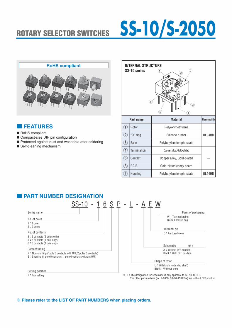
■ FEATURES● RoHS compliant● Compact-size DIP pin configuration● Protected against dust and washable after soldering● Self-cleaning mechanism
Part name
①
②
③
④
⑤
⑥ P.C.B.
Base
Rotor
Contact
“O” ring
Terminal pin
Material Flammability
UL94HB
—
Polybutyleneterephthalate
Silicone rubber
Polybutyleneterephthalate
Copper alloy, Gold-plated
Gold-plated epoxy board
⑦ Housing UL94HB
Polyoxymethylene
■ PART NUMBER DESIGNATION
INTERNAL STRUCTURESS-10 series
SS-10 - 1 6 S P - L - A E WSeries name
No. of poles1:1 pole2:2 poles
No. of contacts3:3 contacts (2 poles only)5:5 contacts (1 pole only)6:6 contacts (1 pole only)
Schematic ※ 1
Shape of rotor
A:Without OFF positionBlank:With OFF position
Form of packagingW:Tray packagingBlank:Plastic bag
Terminal pinE:Au (Lead-free)
L:With knob (extended shaft)Blank:Without knob
※ Please refer to the LIST OF PART NUMBERS when placing orders.
Setting positionP:Top setting
Contact timingN:Non-shorting (1pole 6 contacts with OFF, 2 poles 3 contacts)S:Shorting (1 pole 5 contacts, 1 pole 6 contacts without OFF)
※ 1:The designation for schematic is only aplicable to SS-10-16 □□ .The other partnumbers (ex. S-2050, SS-10-15SPEW) are without OFF position.
12
7
3
45
6
SS-10 構造図 SS-10/S-2050ROTARY SELECTOR SWITCHES
Copper alloy, Gold-plated
RoHS compliant
Tray packagingPlastic bagTray packagingPlastic bagTray packagingPlastic bagTray packagingPlastic bagTray packagingPlastic bagTray packagingPlastic bagTray packagingPlastic bagTray packagingPlastic bagTray packagingPlastic bagTray packagingPlastic bagTray packagingPlastic bagTray packagingPlastic bag
SS-10/S-2050ROTARY SELECTOR SWITCHES
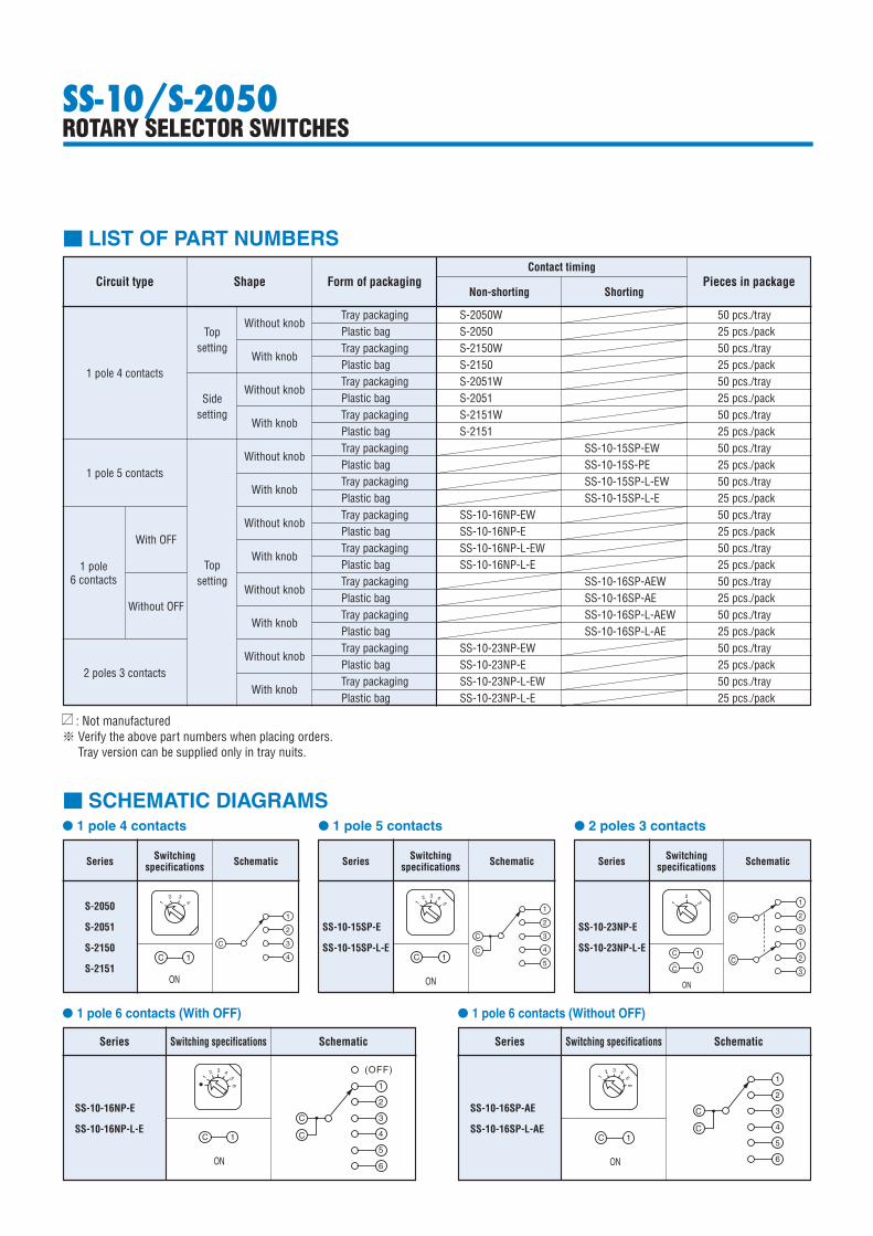
■ LIST OF PART NUMBERS
Circuit type Shape Form of packagingContact timing
Pieces in package
Top setting
Side setting
Without knob
With knob
Without knob
With knob
Without knob
With knob
Without knob
With knob
Without knob
With knob
Without knob
With knob
S-2050W 50 pcs./tray S-2050 25 pcs./pack S-2150W 50 pcs./tray S-2150 25 pcs./pack S-2051W 50 pcs./tray S-2051 25 pcs./pack S-2151W 50 pcs./tray S-2151 25 pcs./pack SS-10-15SP-EW 50 pcs./tray SS-10-15S-PE 25 pcs./pack SS-10-15SP-L-EW 50 pcs./tray SS-10-15SP-L-E 25 pcs./pack SS-10-16NP-EW 50 pcs./tray SS-10-16NP-E 25 pcs./pack SS-10-16NP-L-EW 50 pcs./tray SS-10-16NP-L-E 25 pcs./pack SS-10-16SP-AEW 50 pcs./tray SS-10-16SP-AE 25 pcs./pack SS-10-16SP-L-AEW 50 pcs./tray SS-10-16SP-L-AE 25 pcs./pack SS-10-23NP-EW 50 pcs./tray SS-10-23NP-E 25 pcs./pack SS-10-23NP-L-EW 50 pcs./tray SS-10-23NP-L-E 25 pcs./pack
1 pole 4 contacts
1 pole 5 contacts
1 pole6 contacts
With OFF
Without OFF
2 poles 3 contacts
Top setting
: Not manufactured※ Verify the above part numbers when placing orders.
Tray version can be supplied only in tray nuits.
Non-shorting Shorting
ON
C
1
2
3
C 1 2
3
C
1
2
1 3
C
1
ON
C
1
2
3
C 1 2
3
C
1
2
1 3
C
1
ON
C
1
2
3
C 1 2
3
C
1
2
1 3
C
1
1
2 3 4
5
ON
C 1
C
1
C
2
3
4
5
1
2 3 4
5
ON
C 1
C
1
C
2
3
4
5
1
2 3 4
5
ON
C 1
C
1
C
2
3
4
5
■ SCHEMATIC DIAGRAMS
Series
SS-10-15SP-E
SS-10-15SP-L-E
Switching specifications Schematic Series Switching
specifications Schematic
● 1 pole 5 contacts
SS-10-23NP-E
SS-10-23NP-L-E
● 2 poles 3 contacts
1
2 3 4
56
ON
C 1
C
1
C
2
3
4
5
6
1
2 3 4
56
ON
C 1
C
1
C
2
3
4
5
6
1
2 3 4
56
ON
C 1
C
1
C
2
3
4
5
6
1
2 3 4
56
ON
C 1
C
1
C
2
3
4
5
6
(OFF)
1
2 3 4
56
ON
C 1
C
1
C
2
3
4
5
6
(OFF)
1
2 3 4
56
ON
C 1
C
1
C
2
3
4
5
6
(OFF)
Series
SS-10-16NP-E
SS-10-16NP-L-E
Switching specifications Schematic
● 1 pole 6 contacts (With OFF)
Series
SS-10-16SP-AE
SS-10-16SP-L-AE
Switching specifications Schematic
● 1 pole 6 contacts (Without OFF)
1
ON
C 1
C
1
2
3
4
2 3
4
1
ON
C 1
C
1
2
3
4
2 3
4
1
ON
C 1
C
1
2
3
4
2 3
4
S-2050
S-2051
S-2150
S-2151
Series Switching specifications Schematic
● 1 pole 4 contacts
SS-10/S-2050ROTARY SELECTOR SWITCHES
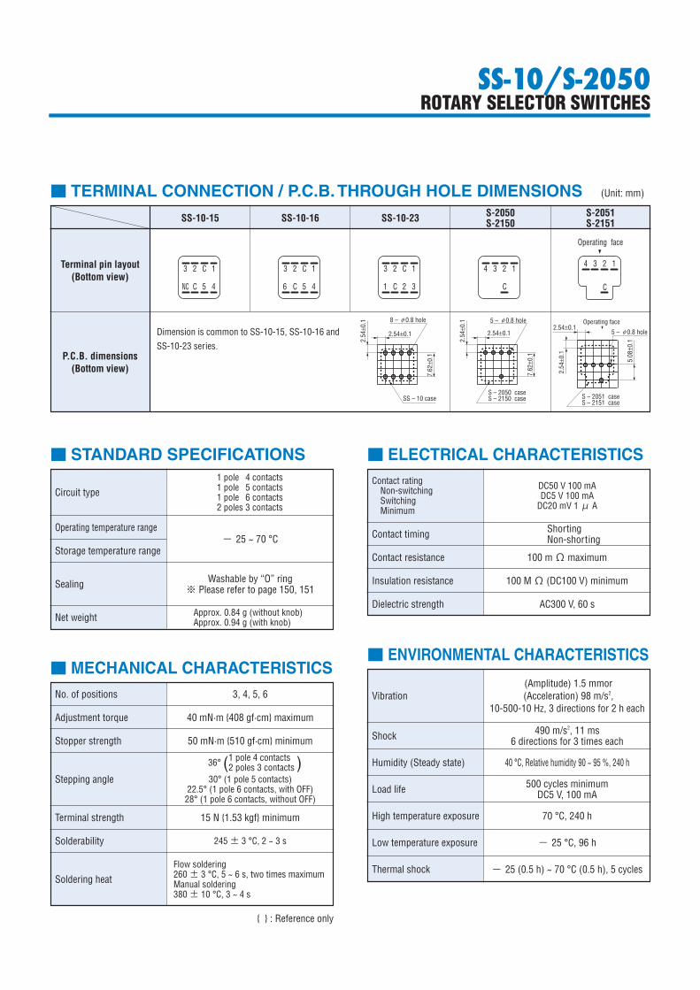
■ STANDARD SPECIFICATIONS
Circuit type
Operating temperature range
Storage temperature range
Sealing
Net weight
1 pole 4 contacts1 pole 5 contacts1 pole 6 contacts2 poles 3 contacts
− 25 ~ 70 °C
Washable by “O” ring※ Please refer to page 150, 151
Approx. 0.84 g (without knob)Approx. 0.94 g (with knob)
■ MECHANICAL CHARACTERISTICSNo. of positions 3, 4, 5, 6
Adjustment torque
Stopper strength
40 mN·m {408 gf·cm} maximum
50 mN·m {510 gf·cm} minimum
Stepping angle 30° (1 pole 5 contacts)22.5° (1 pole 6 contacts, with OFF)
28° (1 pole 6 contacts, without OFF)
Terminal strength 15 N {1.53 kgf} minimum
Solderability 245 ± 3 °C, 2 ~ 3 s
Soldering heatFlow soldering260 ± 3 °C, 5 ~ 6 s, two times maximumManual soldering380 ± 10 °C, 3 ~ 4 s
■ ELECTRICAL CHARACTERISTICSContact rating
Non-switchingSwitchingMinimum
Contact resistance
Insulation resistance
Dielectric strength
DC50 V 100 mADC5 V 100 mA
DC20 mV 1 μ A
100 mΩ maximum
Contact timing ShortingNon-shorting
100 MΩ (DC100 V) minimum
AC300 V, 60 s
■ ENVIRONMENTAL CHARACTERISTICS
Vibration
Shock
Humidity (Steady state)
Load life
High temperature exposure
Low temperature exposure
Thermal shock
(Amplitude) 1.5 mmor (Acceleration) 98 m/s2,
10-500-10 Hz, 3 directions for 2 h each
490 m/s2, 11 ms6 directions for 3 times each
40 °C, Relative humidity 90 ~ 95 %, 240 h
500 cycles minimumDC5 V, 100 mA
70 °C, 240 h
− 25 °C, 96 h
− 25 (0.5 h) ~ 70 °C (0.5 h), 5 cycles
1 pole 4 contacts2 poles 3 contacts36° ( )
{ } : Reference only
SS-10端子接続
3 2 C 1
2.54±0.1
8 – 0.8 hole
7.62
±0.1
2.54
±0.1
SS – 10 case
2.54±0.1
5.08
±0.1
2.54
±0.1
S – 2151 case
Operating face
NC C 5 4
3 2 C 1
C 5 4
3 2 C 1
C 2 36 1
4 3 2 1
C
4 3 2 1
C
2.54±0.1
7.62
±0.1
2.54
±0.1
S – 2051 case
Operating face
φ 5 – 0.8 holeφ
5 – 0.8 holeφ
S – 2150 caseS – 2050 case
■ TERMINAL CONNECTION / P.C.B. THROUGH HOLE DIMENSIONS (Unit: mm)
SS-10-15 SS-10-16 SS-10-23 S-2050 S-2051 S-2150 S-2151
Terminal pin layout(Bottom view)
P.C.B. dimensions(Bottom view)
Dimension is common to SS-10-15, SS-10-16 andSS-10-23 series.
4. 5 ± 0.5
2.54
2.54
2.54
8 –
0.5
± 0.
1t =
0.2
7.62
1
C23
4
5CNC
710
0.7 W × 3.2 L × 1 D
Part No., Production date code &Lead-free Identification mark
10
SS
–10
30˚
10
0.7 W × 3.2 L × 1 D
Part No., Production date code & Lead-free Identification mark
4.5 ± 0.5
2.54
2.54
2.54
8 –
0.5
± 0.
1t =
0.2
1 1
C23
4
5C6
7
10
28˚
SS
–10
23456
7.62
4.5 ± 0.5
2.54
2.54
2.54
8 –
0.5
± 0.
1t =
0.2
1
C23
4
5C6
710
0.7 W × 3.2 L × 1 D
Part No., Production date code &Lead-free Identification mark
3
10
SS
–10
21
456
22.5˚
7.62
10
0.7 W × 3.2 L × 1 D
Part No., Production date code & Lead-free Identification mark
4.5 ± 0.5
2.54
2.54
2.54
t = 0
.2
23
1 1
C23
3
2
C
1
7
10
36˚
SS
–10
8 –
0.5
± 0.
1t =
0.2
7.62
4.5 ± 0.5
2.54
2.54
2.54
8 –
0.5
± 0.
1t =
0.2
1
C23
4
5C
NC
76.6
3.9
Straight knurl
10
0.7 W × 1 D
Part No., Production date code &Lead-free Identification mark
10
SS
–10
30˚
M = 0.2
7.62
10
0.7 W × 1 D
Part No., Production date code &Lead-free Identification mark
3
10
SS
–10
21
456
22.5˚
4.5 ± 0.5
2.54
2.54
2.54
8 –
0.5
± 0.
1t =
0.2
1
C23
4
5C6
76.6
3.9
M = 0.2Straight knurl
7.62
4.5 ± 0.5
2.54
2.54
2.54
8 –
0.5
± 0.
1t =
0.2
1
C23
4
5C6
76.6
3.9
M = 0.2Straight knurl
10
0.7 W × 1 D
Part No., Production date code &Lead-free Identification mark
1
10
28˚
SS
–10
23456
7.62
10
0.7 W × 1 D
Part No., Production date code & Lead-free Identification mark
4.5 ± 0.5
2.54
t = 0
.2
23
1 1
C23
3
2
C
1
7
10
36˚
SS
–10
6.6
3.9
M = 0.2Straight knurl
2.54
2.54
8 –
0.5
± 0.
1
7.62
SS-10/S-2050ROTARY SELECTOR SWITCHES
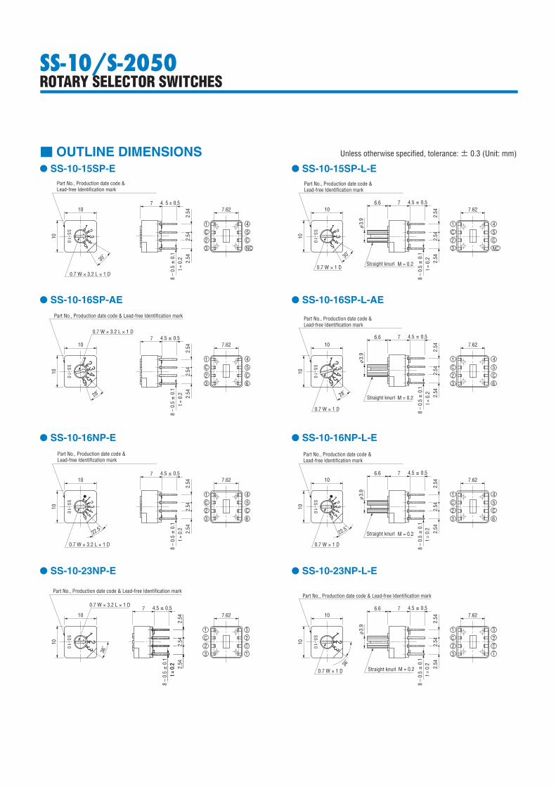
■ OUTLINE DIMENSIONS Unless otherwise specified, tolerance: ± 0.3 (Unit: mm)
● SS-10-15SP-E
● SS-10-16SP-AE
● SS-10-16NP-E
● SS-10-23NP-E
● SS-10-15SP-L-E
● SS-10-16SP-L-AE
● SS-10-16NP-L-E
● SS-10-23NP-L-E
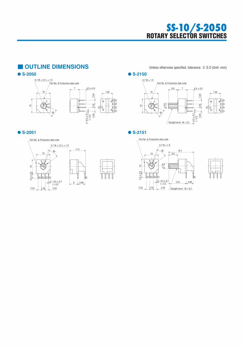
■ OUTLINE DIMENSIONS Unless otherwise specified, tolerance: ± 0.3 (Unit: mm)
● S-2050
● S-2051
● S-2150
S-2050 外形図
10
7
10
0.7 W × 3.2 L × 1 DPart No. & Production date code
4.5 ± 0.5
2.54
2.54
2.54
5–0.
5 ±
0.1
t = 0
.27.62
C
4
3
2
1
1 23
4
36˚
S-2051 外形図
11.5
5.08
C
6
10
10
0.7 W × 3.2 L × 1 D
Part No. & Production date code
432
1
1234
3.5 ±
0.5
5 – 0.5 ± 0.1t = 0.2
2.542.54 2.54
36˚ 18.1
5.08
C
12.6
10
10
0.7 W × 1 D
Part No. & Production date code
432
1
1234
3.5 ±
0.5
5 – 0.5 ± 0.1t = 0.2
2.542.54 2.54
36˚
3.9
Straight knurl M = 0.2
6.6
φ
S-2150 外形図
10
7
10
0.7 W × 1 DPart No. & Production date code
4.5 ± 0.5
1 23
4
36˚
3.9
Straight knurl
6.6
φ
M = 0.2
2.54
2.54
2.54
5–0.
5 ±
0.1
t = 0
.2
7.62
C
4
3
2
1
● S-2151
SS-10/S-2050ROTARY SELECTOR SWITCHES
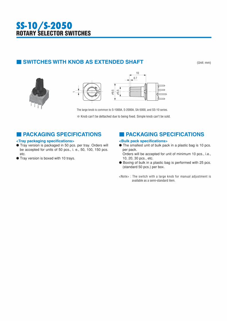
<Note> : The switch with a large knob for manual adjustment is available as a semi-standard item.
The large knob is common to S-1000A, S-2000A, SA-5000, and SS-10 series.
※ Knob can’t be dettached due to being fixed. Simple knob can’t be sold.
S-1000長軸用ツマミ付き
10
0.7
5.
5
9.
5
1
φ φ
SS-10/S-2050ROTARY SELECTOR SWITCHES
■ PACKAGING SPECIFICATIONS■ PACKAGING SPECIFICATIONS<Bulk pack specifications>● The smallest unit of bulk pack in a plastic bag is 10 pcs.
per pack.Orders will be accepted for unit of minimum 10 pcs., i.e., 10, 20, 30 pcs., etc.
● Boxing of bulk in a plastic bag is performed with 25 pcs. (standard 50 pcs.) per box.
■ SWITCHES WITH KNOB AS EXTENDED SHAFT (Unit: mm)
<Tray packaging specifications>● Tray version is packaged in 50 pcs. per tray. Orders will
be accepted for units of 50 pcs., i. e., 50, 100, 150 pcs. etc.
● Tray version is boxed with 10 trays.