Embed Size (px)
Citation preview

71
Model Designations
SGMGV
SGMGV - 03 A D A 2 1
Code Specifications
1 Without options
BWith holding brake (90 VDC)
CWith holding brake (24 VDC)
DWith oil seal and holding
brake (90 VDC)
EWith oil seal and holding
brake (24 VDC)
S With oil seal
7thdigit
6thdigit
5thdigit
4thdigit
3rddigit
1st+2nddigits
1st+2nd digits Rated Output
Code Specifications
A 200 VAC
D 400 VAC
3rd digit Power Supply Voltage
Code Specifications
3 20-bit absolute (standard)
D 20-bit incremental (standard)
4th digit Serial Encoder
Code Specifications
A Standard
5th digit Design Revision Order
Code Specifications
2 Straight without key (standard)
6Straight with key and tap(optional)
6th digit Shaft End
7th digit Options
Rotary Servomotors
Series
Servomotor
SGMGV
Code Specifications
03 300 W
05 450 W
09 850 W
13 1.3 kW
20 1.8 kW
30 2.9 kW
44 4.4 kW
55 5.5 kW
75 7.5 kW
1A 11 kW
1E 15 kW
72
サーボモーター
SGMJV形回転形
Features Application Examples
Ro
tary
Serv
om
oto
rs
1High-speed driving of feed shafts for various machines
1Wide selection: 300 W to 15 kW capacity, holding brake option
1Mounted serial encoder: 20 bits, high resolution
1Protective structure: IP67
1Machine tools
1Transfer machines
1Material handling machines
1Food processing equipment
SGMGV-03/-05
The connectors are used only for Yaskawa servomotors. Order the
connectors specified by Yaskawa.
Both protective structure IP67 and European Safety Standards
compliant connectors are available.
For details, refer to page 83 and 84.
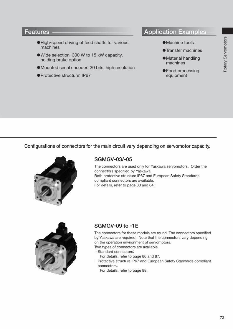
SGMGV-09 to -1E
The connectors for these models are round. The connectors specified
by Yaskawa are required. Note that the connectors vary depending
on the operation environment of servomotors.
Two types of connectors are available.
Standard connectors:
For details, refer to page 86 and 87.
Protective structure IP67 and European Safety Standards compliant
connectors:
For details, refer to page 88.
Configurations of connectors for the main circuit vary depending on servomotor capacity.

73
Ratings and Specifications
Time Rating: Continuous
Vibration Class: V15Insulation Resistance: 500 VDC, 10 MΩ min.
Ambient Temperature: 0 to 40˚C
Excitation: Permanent magnet
Mounting: Flange-mounted
Thermal Class: F
Withstand Voltage: 1500 VAC for one minute (200-V Class)
1800 VAC for one minute (400-V Class)
Enclosure: Totally enclosed, self-cooled, IP67
(except for shaft opening)
Ambient Humidity: 20% to 80% (no condensation)
Drive Method: Direct drive
Rotation Direction: Counterclockwise (CCW) with forward run
reference when viewed from the load side
*: These items and torque-motor speed characteristics quoted in combination with a SERVOPACK are at an armature winding temperature of 20˚C.Notes: 1 The values in parentheses are for servomotors with holding brakes. 2 The above specifications show the values under the cooling condition when the following heat sinks are mounted on the servomotors.
SGMGV-03D/-05D: 250 mm × 250 mm × 6 mm (aluminum)
SGMGV-09D/-13D/-20D: 400 mm × 400 mm × 20 mm (iron)
SGMGV-30D/-44D/-55D/-75D: 550 mm × 550 mm × 30 mm (iron)
SGMGV-1AD/-1ED: 650 mm × 650 mm × 35 mm (iron)
Servomotor Model: SGMGV-¡¡¡ 03D 05D 09D 13D 20D 30D 44D 55D 75D 1AD 1ED
Rated Output* kW 0.3 0.45 0.85 1.3 1.8 2.9 4.4 5.5 7.5 11 15
Rated Torque* N m 1.96 2.86 5.39 8.34 11.5 18.6 28.4 35.0 48.0 70.0 95.4
Instantaneous Peak Torque* N m 5.88 8.92 13.8 23.3 28.7 45.1 71.1 87.6 119 175 224
Rated Current* Arms 1.4 1.9 3.5 5.4 8.4 11.9 16.5 20.8 25.7 28.1 37.2
Instantaneous Max. Current* Arms 4 5.5 8.5 14 20 28 40.5 52 65 70 85
Rated Speed* min-1 1500
Max. Speed* min-1 3000 2000
Torque Constant N m/Arms 1.55 1.71 1.72 1.78 1.50 1.70 1.93 1.80 1.92 2.64 2.74
Rotor Moment of Inertia ×10-4 kg m22.48(2.73)
3.33(3.58)
13.9(16)
19.9(22)
26(28.1)
46(54.5)
67.5(76.0)
89.0(97.5)
125(134)
242(261)
303(341)
Rated Power Rate* kW/s15.5 (14.1)
24.6(22.8)
20.9(18.2)
35.0(31.6)
50.9(47.1)
75.2(63.5)
119(106)
138(126)
184(172)
202(188)
300(283)
Rated Angular Acceleration* rad/s27900(7180)
8590(7990)
3880(3370)
4190(3790)
4420(4090)
4040(3410)
4210(3740)
3930(3590)
3840(3580)
2890(2680)
3150(2960)
Applicable SERVOPACK SGDV-¡¡¡¡ 1R9D 1R9D 3R5D 5R4D 8R4D 120D 170D 210D 260D 280D 370D
200-V Class
*1: These items and torque-motor speed characteristics quoted in combination with a SERVOPACK are at an armature winding temperature of 20˚C.
*2: When using SGDV-200A SERVOPACKs with SGMGV-30A servomotors, use these values.Notes: 1 The values in parentheses are for servomotors with holding brakes. 2 The above specifications show the values under the cooling condition when the following heat sinks are mounted on the servomotors.
SGMGV-03A/-05A: 250 mm × 250 mm × 6 mm (aluminum)
SGMGV-09A/-13A/-20A: 400 mm × 400 mm × 20 mm (iron)
SGMGV-30A/-44A/-55A/-75A: 550 mm × 550 mm × 30 mm (iron)
SGMGV-1AA/-1EA: 650 mm × 650 mm × 35 mm (iron)
Servomotor Model: SGMGV-¡¡¡ 03A 05A 09A 13A 20A 30A 44A 55A 75A 1AA 1EA
Rated Output*1 kW 0.3 0.45 0.85 1.3 1.82.9
2.4*24.4 5.5 7.5 11 15
Rated Torque*1 N m 1.96 2.86 5.39 8.34 11.518.6
15.1*228.4 35.0 48.0 70.0 95.4
Instantaneous Peak Torque*1 N m 5.88 8.92 13.8 23.3 28.7 45.1 71.1 87.6 119 175 224
Rated Current*1 Arms 2.8 3.8 6.9 10.7 16.723.8
19.6*232.8 42.1 54.7 58.6 78
Instantaneous Max. Current*1 Arms 8 11 17 28 42 56 84 110 130 140 170
Rated Speed*1 min-1 1500
Max. Speed*1 min-1 3000 2000
Torque Constant N m/Arms 0.776 0.854 0.859 0.891 0.748 0.848 0.934 0.871 0.957 1.32 1.37
Rotor Moment of Inertia ×10-4 kg m22.48
(2.73)
3.33
(3.58)
13.9
(16)
19.9
(22)
26
(28.1)
46
(54.5)
67.5
(76.0)
89.0
(97.5)
125
(134)
242
(261)
303
(341)
Rated Power Rate*1 kW/s15.5
(14.1)
24.6
(22.8)
20.9
(18.2)
35.0
(31.6)
50.9
(47.1)
75.2
(63.5)
119
(106)
138
(126)
184
(172)
202
(188)
300
(283)
Rated Angular Acceleration*1 rad/s27900
(7180)
8590
(7990)
3880
(3370)
4190
(3790)
4420
(4090)
4040
(3410)
4210
(3740)
3930
(3590)
3840
(3580)
2890
(2680)
3150
(2960)
Applicable SERVOPACK SGDV-¡¡¡¡ 3R8A 3R8A 7R6A 120A 180A330A
200A*2330A 470A 550A 590A 780A
400-V Class

74
Servomotors
SGMGVRotary Motors
Ratings and Specifications
Ro
tary
Serv
om
oto
rs
1Holding Brake Electrical Specifications
Servomotor
Model
Servomotor
Rated Output
kW
Holding Brake Specifications
Holding
Torque
N m
Rated Voltage 24 VDC Rated Voltage 90 VDC
Capacity
W
Rated Current
A (at 20˚C)Capacity
W
Rated Current
A (at 20˚C)
SGMGV-03 0.3 4.5 10 0.42 10 0.11
SGMGV-05 0.45 4.5 10 0.42 10 0.11
SGMGV-09 0.85 12.7 10 0.41 10 0.11
SGMGV-13 1.3 19.6 10 0.41 10 0.11
SGMGV-20 1.8 19.6 10 0.41 10 0.11
SGMGV-30 2.9 43.1 18.5 0.77 18.5 0.21
SGMGV-44 4.4 43.1 18.5 0.77 18.5 0.21
SGMGV-55 5.5 72.6 25 1.05 25 0.28
SGMGV-75 7.5 72.6 25 1.05 25 0.28
SGMGV-1A 11 84.3 32 1.33 32 0.36
SGMGV-1E 15 114.6 35 1.46 35 0.39
Notes: 1 The holding brake is only used to hold the load and cannot be used to stop the servomotor. 2 The holding brake open time and holding brake operation time vary depending on which discharge circuit is used. Make sure holding brake
open time and holding brake operation time are correct for your servomotor. 3 A 24-VDC power supply is not included. 4 Refer to page 350 for information on the 90-VDC power supply.
1Torque-Motor Speed Characteristics (200 V/400 V) A : Continuous Duty Zone B : Intermittent Duty Zone
A B A B
SGMGV-75A,-75D SGMGV-1AA,-1AD SGMGV-1EA,-1EDSGMGV-55A,-55D
0 50 100 150 0 50 100 150 200 0 50 100 150 200 2500 20 40 60 80 100
3000
2000
1000
0
2000
1500
1000
500
0
2000
1500
1000
500
0
3000
2000
1000
0
A B A B A BA B
SGMGV-03A,-03D
SGMGV-20A,-20DSGMGV-30A,-30D
(When using with SGDV-330A) SGMGV-44A,-44D
SGMGV-05A,-05D SGMGV-09A,-09D SGMGV-13A,-13D
0 1 2 3 4 5 6 7
0 5 10 15 20 25 30 35
0 1 2 3 4 5 6 7 8 9 10
0 5 10 15 20 25 30 35 40 45 50 0 10 20 30 40 50 60 70 80
0 2 4 6 8 10 12 14 16 0 5 10 15 20 25
3500
3000
2500
2000
1500
1000
500
0
3500
3000
2500
2000
1500
1000
500
0
3500
3000
2500
2000
1500
1000
500
0
3500
3000
2500
2000
1500
1000
500
0
3500
3000
2500
2000
1500
1000
500
0
3500
3000
2500
2000
1500
1000
500
0
3500
3000
2500
2000
1500
1000
500
0
A B
A B A B A B
A B A B A B
Mot
or S
peed
(m
in-1)
Mot
or S
peed
(m
in-1)
Mot
or S
peed
(m
in-1)
Mot
or S
peed
(m
in-1)
Mot
or S
peed
(m
in-1)
Mot
or S
peed
(m
in-1)
Mot
or S
peed
(m
in-1)
Mot
or S
peed
(m
in-1)
Mot
or S
peed
(m
in-1)
Mot
or S
peed
(m
in-1)
Mot
or S
peed
(m
in-1)
Torque (N�m)
Torque (N�m) Torque (N�m)
SGMGV-30A (When using with SGDV-200A)
0 5 10 15 20 25 30 35 40 45 50
3500
3000
2500
2000
1500
1000
500
0
Mot
or S
peed
(m
in-1)
Torque (N�m) Torque (N�m)
Torque (N�m) Torque (N�m) Torque (N�m) Torque (N�m)
Torque (N�m) Torque (N�m) Torque (N�m)
A B
Notes: 1 When the effective torque is within the rated torque, the servomotor can be used within the intermittent duty zone.2 When the main circuit cable length exceeds 20 m, note that the intermittent duty zone of the Torque-Motor Speed Characteristics will shrink as the line-
to-line voltage drops.

75
Ratings and Specifications
1Allowable Load Moment of Inertia at the Motor Shaft
The rotor moment of inertia ratio is the value for a servomotor without a gear and a holding brake.
Servomotor ModelServomotor
Rated Output
Allowable Load Moment of Inertia(Rotor Moment of Inertia Ratio)
SGMGV-03 to -1E 0.3 to 1.5 kW 5 times
1Load Moment of Inertia
The larger the load moment of inertia, the worse the movement response of the load.
The allowable load moment of inertia (JL) depends on the motor capacity, as shown above. This value is provided
strictly as a guideline and results may vary depending on servomotor drive conditions.
Use the AC servo drive capacity selection program SigmaJunmaSize+ to check the operation conditions.
The program can be downloaded for free from our web site (http://www.e-mechatronics.com/).
An overvoltage alarm (A.400) is likely to occur during deceleration if the load moment of inertia exceeds the
allowable load moment of inertia. SERVOPACKs with a built-in regenerative resistor may generate a regenerative
overload alarm (A.320). Take one of the following steps if this occurs.
Reduce the torque limit.
Reduce the deceleration rate.
Reduce the maximum speed.
Install an external regenerative resistor if the alarm cannot be cleared using the steps above. Refer to
Regenerative Resistors on page 351.
1Allowable Radial and Thrust Loads
Design the mechanical system so thrust and radial loads applied to the servomotor shaft end during operation fall
within the ranges shown in the table.
Servomotor ModelAllowable Radial
Load (Fr) N
Allowable Thrust
Load (Fs) N
LF
mmReference Diagram
SGMGV-
03¡¡A21 490 98 37
05¡¡A21 490 98 40
09¡¡A21 490 98 58
13¡¡A21 686 343 58
20¡¡A21 980 392 58
30¡¡A21 1470 490 79
44¡¡A21 1470 490 79
55¡¡A21 1764 588 113
75¡¡A21 1764 588 113
1A¡¡A21 1764 588 116
1E¡¡A21 4998 2156 116
Fr
Fs
LF

76
Servomotors
SGMGVRotary Motors
External Dimensions Units: mm
1Without Holding Brakes(1) 300 W, 450 W
R1
S Di
a.
Q
18 D
ia.
5
LR
Shaft End
Note: For the specifications of the other shaft ends, refer to page 82.
35 D
ia.
100 Dia.¡90120 Dia.
50
1738
80D
ia.
0 -0.0
30
S Di
a.
LLL
LM36LR
510
KB1KB2
70
4-6.6 Dia. Mounting HolesA
79 D
ia.
0.04 A
0.04 Dia. A
0.02
Model
SGMGV-L LL LM LR KB1 KB2
Shaft End Dimensions Approx. Mass
kgS Q
03¡¡A21 163 126 90 37 75 114 14 0-0.011 25 2.6
05¡¡A21 179 139 103 40 88 127 16 0-0.011 30 3.2
Note: Models with oil seals are of the same configuration.
3
7
10 8
4
1
Cable Specifications for Encoder-end Connector (20-bit Encoder)
Receptacle: CM10-R10P-DApplicable plug (To be provided by the customer)
Plug: CM10-AP10S-¡-D (L-shaped)
CM10-SP10S-¡-D (Straight)
(Boxes (¡) indicate a value that varies, depending on cable size.)
Manufacturer: DDK Ltd.
1 PS 6 BAT (+)
2 /PS 7 −3 − 8 −4 PG 5V 9 PG 0V
5 BAT (−) 10 FG (Frame ground)
With an Absolute Encoder
1 PS 6 −2 /PS 7 −3 − 8 −4 PG 5V 9 PG 0V
5 − 10 FG (Frame ground)
With an Incremental Encoder
û Cable Specifications for Servomotor-end Connector
PE FG (Frame ground)
5 −4 −3 Phase U
2 Phase V
1 Phase W
12
34
5P
E
Manufacturer: Japan Aviation Electronics Industry,Ltd.
Ro
tary
Serv
om
oto
rs

77
External Dimensions Units: mm
LE
LR
44 D
ia.
R1
LE
LR
28 D
ia.
Q
R1
S Dia.
45 D
ia.S
Dia.
Q
Shaft End
SGMGV-30 to -75SGMGV-09 to -20
Note: For the specifications of the other shaft ends, refer to page 82.
LA Dia.
17
36
L
LL LR
LMLG LE
S Di
a.
LB D
ia.
50K
L1
KB1KB2
IE
LH Dia.
0.04
0.04 A
0.04 Dia. A
0.02
**: When using SGMGV-55 and -75 servomotors
A4-LZ Dia. Mounting Holes
79 D
ia.
62 D
ia.
Model
SGMGV-L LL LM LR KB1 KB2 IE KL1
Flange Face DimensionsShaft End
DimensionsApprox.
Mass
kgLA LB LC LE LG LH LZ S Q
09¡¡A21 195 137 101 58 83 125 – 104 145 110 0-0.035 130 6 12 165 9 19 0
-0.013 40 5.5
13¡¡A21 211 153 117 58 99 141 – 104 145 110 0-0.035 130 6 12 165 9 22 0
-0.013 40 7.1
20¡¡A21 229 171 135 58 117 159 – 104 145 110 0-0.035 130 6 12 165 9 24 0
-0.013 40 8.6
30¡¡A21 239 160 124 79 108 148 – 134 200 114.3 0-0.025 180 3.2 18 230 13.5 35+0.01
0 76 13.5
44¡¡A21 263 184 148 79 132 172 – 134 200 114.3 0-0.025 180 3.2 18 230 13.5 35+0.01
0 76 17.5
55□□A21 334 221 185 113 163 209 123 144 200 114.3 0-0.025 180 3.2 18 230 13.5 42 0
-0.016 110 21.5
75□□A21 380 267 231 113 209 255 123 144 200 114.3 0-0.025 180 3.2 18 230 13.5 42 0
-0.016 110 29.5
Note: Models with oil seals are of the same configuration.
3
7
10 8
4
1
Cable Specifications for Encoder-end Connector (20-bit Encoder)
Receptacle: CM10-R10P-DApplicable plug (To be provided by the customer)
Plug: CM10-AP10S-¡-D (L-shaped)
CM10-SP10S-¡-D (Straight)
(Boxes (¡) indicate a value that varies, depending on cable size.)
Manufacturer: DDK Ltd.
Cable Specifications for Servomotor-end Connector
A Phase U
B Phase V
C Phase W
D FG (Frame ground)
1 PS 6 BAT (+)
2 /PS 7 −3 − 8 −4 PG 5V 9 PG 0V
5 BAT (−) 10 FG (Frame ground)
With an Absolute Encoder
1 PS 6 −2 /PS 7 −3 − 8 −4 PG 5V 9 PG 0V
5 − 10 FG (Frame ground)
With an Incremental Encoder
A
BC
D
(2) 850 W to 7.5 kW
Manufacturer: DDK Ltd.

78
Servomotors
SGMGVRotary Motors
External Dimensions Units: mm
Shaft End
Note: For the specifications of the other shaft ends, refer to page 82.
R1
LA Dia.
LH Dia.
IE
□LC
56 56
LR
LE
LM
LL
L
LR
36
LG LE
S D
ia.
LB D
ia.
KB2
KB1
50K
L1
17
S1 D
ia.
110
S D
ia.
0.04
0.06 A
0.04 Dia. A
A
79 D
ia.
80 D
ia.
4-LZ Dia. Mounting Holes
Note: Models with oil seals are of the same configuration.
(3) 11 kW, 15 kW
Model
SGMGV-L LL LM LR KB1 KB2 IE KL1
Flange Face DimensionsShaft End
DimensionsApprox.
Mass
kgLA LB LC LE LG LH LZ S S1
1A□□A21 447 331 295 116 247 319 150 168 235 200 0-0.046 220 4 20 270 13.5 42 0
-0.016 50 57
1E□□A21 509 393 357 116 309 381 150 168 235 200 0-0.046 220 4 20 270 13.5 55+0.030
+0.011 60 67
3
7
10 8
4
1
Cable Specifications for Encoder-end Connector (20-bit Encoder)
Receptacle: CM10-R10P-DApplicable plug (To be provided by the customer)
Plug: CM10-AP10S-¡-D (L-shaped)
CM10-SP10S-¡-D (Straight)
(Boxes (¡) indicate a value that varies, depending on cable size.)
Manufacturer: DDK Ltd.
Cable Specifications for Servomotor-end Connector
A Phase U
B Phase V
C Phase W
D FG (Frame ground)
1 PS 6 BAT (+)
2 /PS 7 −3 − 8 −4 PG 5V 9 PG 0V
5 BAT (−) 10 FG (Frame ground)
With an Absolute Encoder
1 PS 6 −2 /PS 7 −3 − 8 −4 PG 5V 9 PG 0V
5 − 10 FG (Frame ground)
With an Incremental Encoder
A
BC
D
Manufacturer: DDK Ltd.
Ro
tary
Serv
om
oto
rs

79
External Dimensions Units: mm
1With Holding Brakes(1) 300 W, 450 W
R1
S Dia.
Q18 D
ia.
5
LR
Shaft End
Note: For the specifications of the other shaft ends, refer to page 82.
35 D
ia.
100 Dia.¡90120 Dia.
80D
ia.
0 -0.0
30KB1
KB2
S Di
a.
10 5LM
LLL
LR36
7050
1738
4-6.6 Dia. Mounting HolesA
79 D
ia.
0.04 A
0.04 Dia. A
0.02
Model
SGMGV-L LL LM LR KB1 KB2
Shaft End Dimensions Approx. Mass
kgS Q
03¡¡A2¡ 196 159 123 37 75 147 14 0-0.011 25 3.6
05¡¡A2¡ 212 172 136 40 88 160 16 0-0.011 30 4.2
Note: Models with oil seals are of the same configuration.
3
7
10 8
4
1
Cable Specifications for Encoder-end Connector (20-bit Encoder)
Receptacle: CM10-R10P-DApplicable plug (To be provided by the customer)
Plug: CM10-AP10S-¡-D (L-shaped)
CM10-SP10S-¡-D (Straight)
(Boxes (¡) indicate a value that varies, depending on cable size.)
Manufacturer: DDK Ltd.
Cable Specifications for Servomotor-end Connector
PE FG (Frame ground)
5 Brake terminal
4 Brake terminal
3 Phase U
2 Phase V
1 Phase W
1 PS 6 BAT (+)
2 /PS 7 −3 − 8 −4 PG 5V 9 PG 0V
5 BAT (−) 10 FG (Frame ground)
With an Absolute Encoder
1 PS 6 −2 /PS 7 −3 − 8 −4 PG 5V 9 PG 0V
5 − 10 FG (Frame ground)
With an Incremental Encoder
12
34
5P
E
Manufacturer: Japan Aviation Electronics Industry,Ltd.

80
Servomotors
SGMGVRotary Motors
External Dimensions Units: mm
(2) 850 W to 7.5 kW
LE
LR
44 D
ia.
R1
LE
LR
28 D
ia.
Q
R1
S Dia.
45 D
ia.
S Di
a.
Q
Shaft End
SGMGV-30 to -75SGMGV-09 to -20
Note: For the specifications of the other shaft ends, refer to page 82.
62 D
ia.
LA Dia.
LH Dia.
36
50
1711
IE
LELG
LLL
LRLM
LB D
ia.
S Dia.
KB1KB3
KB2
KL1 KL3
0.040.02
A 4-LZ Dia. Mounting Holes
79 D
ia.
0.04 A
0.04 Dia. A
**: When using SGMGV-55 and -75 servomotors
ModelSGMGV-
L LL LM LR KB1 KB2 KB3 IE KL1 KL3Flange Face Dimensions
Shaft End Dimensions
Approx.Mass
kgLA LB LC LE LG LH LZ S Q
09¡¡A2¡ 231 173 137 58 83 161 115 – 104 80 145 110 0-0.035 130 6 12 165 9 19 0
-0.013 40 7.5
13¡¡A2¡ 247 189 153 58 99 177 131 – 104 80 145 110 0-0.035 130 6 12 165 9 22 0
-0.013 40 9.0
20¡¡A2¡ 265 207 171 58 117 195 149 – 104 80 145 110 0-0.035 130 6 12 165 9 24 0
-0.013 40 11.0
30¡¡A2¡ 287 208 172 79 108 196 148 – 134 110 200 114.3 0-0.025 180 3.2 18 230 13.5 35+0.01
0 76 19.5
44¡¡A2¡ 311 232 196 79 132 220 172 – 134 110 200 114.3 0-0.025 180 3.2 18 230 13.5 35+0.01
0 76 23.5
55¡¡A2¡ 378 265 229 113 163 253 205 123 144 110 200 114.3 0-0.025 180 3.2 18 230 13.5 42 0
-0.016 110 27.5
75¡¡A2¡ 424 311 275 113 209 299 251 123 144 110 200 114.3 0-0.025 180 3.2 18 230 13.5 42 0
-0.016 110 35
Note: Models with oil seals are of the same configuration.
3
7
10 8
4
1
Cable Specifications for Encoder-end Connector (20-bit Encoder)
Receptacle: CM10-R10P-DApplicable plug (To be provided by the customer)
Plug: CM10-AP10S-¡-D (L-shaped)
CM10-SP10S-¡-D (Straight)
(Boxes (¡) indicate a value that varies, depending on cable size.)
Manufacturer: DDK Ltd.
Cable Specifications for Servomotor-end Connector
A Phase U
B Phase V
C Phase W
D FG (Frame ground)
1 PS 6 BAT (+)
2 /PS 7 −3 − 8 −4 PG 5V 9 PG 0V
5 BAT (−) 10 FG (Frame ground)
With an Absolute Encoder
1 PS 6 −2 /PS 7 −3 − 8 −4 PG 5V 9 PG 0V
5 − 10 FG (Frame ground)
With an Incremental Encoder
A
BC
D
Cable Specifications for Brake-end Connector
Receptacle: CM10-R2P-DApplicable plug (To be provided by the customer)
Plug: CM10-AP2S-¡-D (L-shaped)
CM10-SP2S-¡-D (Straight)
(Boxes (¡) indicate a value that varies, depending on cable size.)
Manufacturer: DDK Ltd.
Brake terminal
Brake terminal
1
2
Note: No polarity for connection to the brake terminals
Manufacturer: DDK Ltd.
Ro
tary
Serv
om
oto
rs

81
3
7
10 8
4
1
Cable Specifications for Encoder-end Connector (20-bit Encoder)
Receptacle: CM10-R10P-DApplicable plug (To be provided by the customer)
Plug: CM10-AP10S-¡-D (L-shaped)
CM10-SP10S-¡-D (Straight)
(Boxes (¡) indicate a value that varies, depending on cable size.)
Manufacturer: DDK Ltd.
Cable Specifications for Servomotor-end Connector
A Phase U
B Phase V
C Phase W
D FG (Frame ground)
1 PS 6 BAT (+)
2 /PS 7 −3 − 8 −4 PG 5V 9 PG 0V
5 BAT (−) 10 FG (Frame ground)
With an Absolute Encoder
1 PS 6 −2 /PS 7 −3 − 8 −4 PG 5V 9 PG 0V
5 − 10 FG (Frame ground)
With an Incremental Encoder
A
BC
D
Cable Specifications for Brake-end Connector
Receptacle: CM10-R2P-DApplicable plug (To be provided by the customer)
Plug: CM10-AP2S-¡-D (L-shaped)
CM10-SP2S-¡-D (Straight)
(Boxes (¡) indicate a value that varies, depending on cable size.)
Manufacturer: DDK Ltd.
Brake terminal
Brake terminal
1
2
Note: No polarity for connection to the brake terminals
Manufacturer: DDK Ltd.
(3) 11 kW, 15 kW
Shaft End
Note: For the specifications of the other shaft ends, refer to page 82.
R1
LA Dia.
LH Dia.
IE
□LC
56 56
LRLE
S D
ia.
LB D
ia.
LL LRLM
LG LE36
KB1
KB3
KB2
50K
L3K
L1
11 17
L
S1
Dia
.
S Di
a.
110
0.04
0.04 Dia. A
A
0.06 A
79 D
ia.
80 D
ia.
4-LZ Dia. Mounting Holes
Note: Models with oil seals are of the same configuration.
ModelSGMGV-
L LL LM LR KB1 KB2 KB3 IE KL1 KL3Flange Face Dimensions
Shaft End
DimensionsApprox.
Mass
kgLA LB LC LE LG LH LZ S S1
1A¡¡A2¡ 498 382 346 116 247 370 315 150 168 125 235 200 0-0.046 220 4 20 270 13.5 42 0
-0.016 50 65
1E¡¡A2¡ 598 482 446 116 309 470 385 150 168 125 235 200 0-0.046 220 4 20 270 13.5 55+0.030
+0.011 60 85
External Dimensions Units: mm

82
Servomotors
SGMGVRotary Motors
Code Specifications Remarks
2 Straight without key Standard
6Straight with key and tap for one location (Key slot is JIS B1301-1996 fastening type)
Optional
1Shaft End
SGMGV - ¡¡¡¡¡¡¡
Shaft EndModel SGMGV-
03 05 09 13 20 30/44 55/75 1A 1E
Code: 2 (Straight without Key)
LR 37 40 58 58 58 79 113 116 116
Q 25 30 40 40 40 76 110 110 110
S 14 0−0.011 16
0−0.011 19
0−0.013 22
0−0.013 24
0−0.013 35
+0.01 0 42
0−0.016 42
0−0.016 55
+0.030+0.011
Code: 6 (Straight with Key and Tap)
LR 37 40 58 58 58 79 113 116 116
Q 25 30 40 40 40 76 110 110 110
QK 15 20 25 25 25 60 90 90 90
S 14 0−0.011 16
0−0.011 19
0−0.013 22
0−0.013 24
0−0.013 35
+0.01 0 42
0−0.016 42
0−0.016 55
+0.030+0.011
W 5 5 5 6 8 10 12 12 16
T 5 5 5 6 7 8 8 8 10
U 3 3 3 3.5 4 5 5 5 6
PM4 Screw,Depth 10
M5 Screw, Depth 12M12 Screw,
Depth 25M16 Screw,
Depth 32M20 Screw,
Depth 40
LR
Q
R1 S Dia.
LR
QQK
U
R1
P
T
W S D
ia.
External Dimensions Units: mm
Ro
tary
Serv
om
oto
rs

83
(Cont’d)
Selecting Cables (SGMGV-03 / -05)
1Servomotor Main Circuit Cable
Servomotor
Rated
Output
Name LengthOrder No.
Specifications DetailsStandard (Flexible) Type*
0.3 kW
0.45 kW
For Servomotor without
Holding Brakes
3 m JZSP-CVM21-03-E
(1)
5 m JZSP-CVM21-05-E
10 m JZSP-CVM21-10-E
15 m JZSP-CVM21-15-E
20 m JZSP-CVM21-20-E
30 m JZSP-CVM21-30-E
40 m JZSP-CVM21-40-E
50 m JZSP-CVM21-50-E
For Servomotor with
Holding Brakes
3 m JZSP-CVM41-03-E
(2)
5 m JZSP-CVM41-05-E
10 m JZSP-CVM41-10-E
15 m JZSP-CVM41-15-E
20 m JZSP-CVM41-20-E
30 m JZSP-CVM41-30-E
40 m JZSP-CVM41-40-E
50 m JZSP-CVM41-50-E
Servomotor-end
Connector Kit– JZSP-CVM9-1-E (3)
SERVOPACK End Servomotor End
M4 Crimped TerminalsWire Markers
L50 mm
SERVOPACK End Servomotor End
M4 Crimped TerminalsWire Markers
L50 mm
1Cables Connections2Standard Wiring (Max. encoder cable length: 20 m) 2Encoder Cable Extension from 30 to 50 m
SGDVSERVOPACK
ServomotorMain Circuit Cable(See page 83.)
Encoder Cable (See page 89.)
Battery Case(Required when an absolute encoder is used.)
SGMGV-03/-05Servomotor
SGDVSERVOPACK
(Example)
Relay Encoder Cable(See page 91.)
e Cable with a Battery (Required when an absolute encoder is used.)
q Encoder-end Cable
SGMGV-03/-05Servomotor
w Cable with Connectors, orr CableServomotor
Main Circuit Cable(See page 83.)
(See page 91.)
Crimped Type(A crimp tool is required.)
CAUTION
Separate the servomotor main circuit cable wiring from the I/O signal cable and encoder cable at
least 30 cm, and do not bundle or run them in the same duct.
When the main circuit cable length exceeds 20 m, note that the intermittent duty zone of the
Torque-Motor Speed Characteristics will shrink as the line-to-line voltage drops.
*: These flexible cables are provided as standard equipment.

84
Servomotors
SGMGVRotary Motors
Selecting Cables (SGMGV-03 / -05)
Ro
tary
Serv
om
oto
rs
(1) Wiring Specifi cations for Servomotors without Holding Brakes (2) Wiring Specifi cations for Servomotor with Holding Brakes
Wire Color Signal
Green/yellow FG
Blue Phase W
White Phase V
Red Phase U
SERVOPACK-end Leads
Signal Pin No.
FG PE
Phase W 1
Phase V 2
Phase U 3
– 4
– 5
Servomotor-end Connector
Wire Color Signal
Green/yellow FG
Blue Phase W
White Phase V
Red Phase U
Black Brake
Black Brake
SERVOPACK-end Leads
Signal Pin No.
FG PE
Phase W 1
Phase V 2
Phase U 3
Brake 4
Brake 5
Servomotor-end Connector
Note: No polarity for connection to a holding brake
(3) Servomotor-end Connector Kit Specifications (4) Cable Specifi cations (Flexible Type)
Items For Servomotor without Holding Brakes (4 wires) For Servomotor with Holding Brakes (6 wires)
Order No.* JZSP-CVM29-¡¡-E JZSP-CVM49-¡¡-E
Cable Length 50 m max.
Specifications
UL2586 (Rating temperature: 105˚C)
AWG20×4C
For power line: AWG20
(0.55 mm2)
Outer diameter of insulating
sheath: 1.77 dia.
UL2586 (Rating temperature: 105˚C)
AWG20×6C
For power line: AWG20
(0.55 mm2)
Outer diameter of insulating
sheath: 1.77 dia.
For holding brake line:
AWG20 (0.55 mm2)
Outer diameter of insulating
sheath: 1.77 dia.
Finished Dimensions 7.3±0.3 dia. 7.4±0.3 dia.
Internal
Configuration
and Lead
Color
Yaskawa Standard
Specifications (Standard Length)
Cable length:
3 m, 5 m, 10 m, 15 m, 20 m, 30 m, 40 m, 50 m
*: Specify the cable length in ¡¡ of order no. Example: JZSP-CVM29-05-E (5 m)
Red
Blue
WhiteGreen/yellow
Black
Black
Blue Red
White
Green/yellow
Items Specifications External Dimensions mm
Order No.JZSP-CVM9-1-E(Cables are not included.)
Applicable
ServomotorsSGMGV-03/-05
ManufacturerJapan Aviation
Electronics Industry, Ltd.
Plug JNYFX06SJ3
Electrical
ContactST-TMH-S-C1B
Applicable
Wire SizeAWG18 to 22
Outer Diameter of
Insulating Sheath
1.3 dia. to
1.8 dia.
Mounting
Screw
M3 Pan head
screw
Applicable Cable
Outer Diameter
6.9 dia. to
8.3 dia.
12
34
5PE
39.638
18
*: These flexible cables are provided as standard equipment.
ServomotorRated Output
Name LengthOrder No.
Specifications DetailsStandard (Flexible) Type*
0.3 kW
0.45 kWCables
For Servomotor
without Holding
Brakes (4 wires)
3 m JZSP-CVM29-03-E
(4)
5 m JZSP-CVM29-05-E
10 m JZSP-CVM29-10-E
15 m JZSP-CVM29-15-E
20 m JZSP-CVM29-20-E
30 m JZSP-CVM29-30-E
40 m JZSP-CVM29-40-E
50 m JZSP-CVM29-50-E
For Servomotor
with Holding
Brakes (6 wires)
3 m JZSP-CVM49-03-E
(4)
5 m JZSP-CVM49-05-E
10 m JZSP-CVM49-10-E
15 m JZSP-CVM49-15-E
20 m JZSP-CVM49-20-E
30 m JZSP-CVM49-30-E
40 m JZSP-CVM49-40-E
50 m JZSP-CVM49-50-E
Note: A crimp tool (Model no. : CT160-3-TMH5B) is required. Contact the respective manufacturer for more information.

85
SGDVSERVOPACK
ServomotorMain Circuit Cable
Encoder Cable (See page 89.)
Battery Case(Required when an absolute encoder is used.)
SGMGV-09 to -1EServomotor
SGDVSERVOPACK
(Example)
Relay Encoder Cable(See page 91.)
e Cable with a Battery (Required when an absolute encoder is used.)
q Encoder-end Cable
SGMGV-09 to -1EServomotor
w Cable with Connectors, orr Cable
Selecting Cables (SGMGV-09 to -1E)
1Servomotor Main Circuit Cables
Customers must assemble the servomotor’s main circuit cables and attach connectors to connect the
SERVOPACKs and the SGMGV servomotors.
The connectors specifi ed by Yaskawa are required. Note that the connectors vary depending on the operation
environment of servomotors.
Two types of connectors are available.
Standard connectors
Protective structure IP67 and European Safety Standards compliant connectors
Yaskawa does not specify which cables to use. Use appropriate cables for the connectors.
1Cables Connections2Standard Wiring (Max. encoder cable length: 20 m) 2Encoder Cable Extension from 30 to 50 m
(See page 91.)
CAUTION
Separate the servomotor main circuit cable wiring from the I/O signal cable and encoder cable at
least 30 cm, and do not bundle or run them in the same duct.
When the main circuit cable length exceeds 20 m, note that the intermittent duty zone of the
Torque-Motor Speed Characteristics will shrink as the line-to-line voltage drops.

86
Servomotors
SGMGVRotary Motors
Servomotor-end Connector
Servomotor-end Connector
Brake Power Supply Connector
Selecting Cables (SGMGV-09 to -1E)
1Standard Connectors3Connector Configuration
(1) Without Holding Brakes
Capacity
kW
Servomotor-end
Connector (Receptacle)
Cable-end Connector (Not provided by Yaskawa)
Straight Plug L-shaped Plug Cable Clamp
0.85CE05-2A18-10PD-D(MS3102A18-10P)
MS3106B18-10S MS3108B18-10S MS3057-10A1.3
1.8
2.9 CE05-2A22-22PD-D(MS3102A22-22P)
MS3106B22-22S MS3108B22-22S MS3057-12A4.4
5.5to15
CE05-2A32-17PD-D(MS3102A32-17P)
MS3106B32-17S MS3108B32-17S MS3057-20A
Servomotor-end Connector
For 0.85 to 15 kW
Capacity
kW
Servomotor-end
Connector (Receptacle)
Cable-end Connector (Not provided by Yaskawa)
Straight Plug L-shaped Plug Manufacturer
0.85
to
15
CM10-R2P-D
CM10-SP2S-S-D
Applicable Cable:
4.0 dia. to 6.0 dia.
CM10-AP2S-S-D
Applicable Cable:
4.0 dia. to 6.0 dia.
DDK Ltd.
CM10-SP2S-M-D
Applicable Cable:
6.0 dia. to 9.0 dia.
CM10-AP2S-M-D
Applicable Cable:
6.0 dia. to 9.0 dia.
CM10-SP2S-L-D
Applicable Cable:
9.0 dia. to 11.6 dia.
CM10-AP2S-L-D
Applicable Cable:
9.0 dia. to 11.6 dia.
Brake Power Supply Connector
0.85 to 15 kW
CableClamp
Cable
StraightPlug
L-shaped PlugSGMGV
Servomotor
Servomotor-end Connector(Receptacle)
J Z S P - C V B 9 - S M S2 - E
To order a brake power supply connecter kit (0.85 to 15 kW)
with the order no. below, contact your Yaskawa representative.
Connector Type S: Straight plug A: L-shaped plug
Bush Size*1
S : Size S (4.0 dia. to 6.0 dia.) M : Size M (6.0 dia. to 9.0 dia.) L : Size L (9.0 dia. to 11.6 dia.)
Contact Pin Size S2: Soldered C3: Crimped type*2
*1: A size-M connector kit is available as a standard equipment.
*2: A crimp tool (model: 357J-50448T) by DDK Ltd. is required.
(2) With Holding Brakes
0.85 to 15 kW servomotors require servomotor-end connector and brake power supply connector.
The servomotor-end connector is the same as is used for servomotors without holding brakes.
Notes: 1 Servomotor-end connectors (receptacles) are RoHS-compliant. Contact the respective connector manufacturers for RoHS-compliant cable-end connectors (not provided by Yaskawa).
2 Servomotor-end connectors (receptacles) can be used with MS plugs. For the model number of the MS receptacle, refer to the receptacle number in parentheses and select the appropriate plug.
Ro
tary
Serv
om
oto
rs

87
Selecting Cables (SGMGV-09 to -1E)
3Cable-end Connectors
(1) MS3106B¡¡-¡¡S :
Straight PlugShell
Size
Joint Screw
A
Length of
Joint
Portion
J±0.12
Overall
Length
L max.
Outer
Diameter of
Joint Nut
Q +0−0.38
Cable Clamp
Set Screw
V
Effective
Screw
Length
W min.
Maximum
Width
Y max.
18 1-1/8-18UNEF 18.26 52.37 34.13 1-20UNEF 9.53 42
22 1-3/8-18UNEF 18.26 55.57 40.48 1-3/16-18UNEF 9.53 50
32 2-18UNS 18.26 61.92 56.33 1-3/4-18UNS 11.13 66
(2) MS3108B¡¡-¡¡S :
L-shaped Plug
Shell
Size
Joint Screw
A
Length of
Joint
Portion
J±0.12
Overall
Length
L max.
Outer
Diameter of
Joint Nut
Q +0−0.38
R
±0.5
U
±0.5
Cable Clamp
Set Screw
V
Effective
Screw
Length
W min.
18 1-1/8-18UNEF 18.26 68.27 34.13 20.5 30.2 1-20UNEF 9.53
22 1-3/8-18UNEF 18.26 76.98 40.48 24.1 33.3 1-3/16-18UNEF 9.53
32 2-18UNS 18.26 95.25 56.33 32.8 44.4 1-3/4-18UNS 11.13
(3) MS3057-¡¡A : Cable Clamp with Rubber Bushing
Cable Clamp
Type
Applicable
Connector
Shell Size
Overall
Length
A±0.7
Effective
Screw
Length
C
E
DiameterG±0.7 H
J
Diameter
Set Screw
V
Outer
Diameter
Q±0.7 Dia.
Attached
Bushing
MS3057-10A 18 23.8 10.3 15.9 31.7 3.2 14.3 1-20UNEF 30.1 AN3420-10
MS3057-12A 20,22 23.8 10.3 19 37.3 4 15.9 1-3/16-18UNEF 35.0 AN3420-12
MS3057-20A 32 27.8 11.9 31.7 51.6 6.3 23.8 1-3/4-18UNS 51.6 AN3420-20
J W
A
V
YQ
LU
RW
J
A
Q
L
V
G
H (Slide Range)
E Dia.(Inner Diameter of Cable Clamp)
J Dia. (Inner Diameter of Bushing)
A
V
Q D
ia.
1.6
C
Units: mm
Units: mm
Units: mm
3Dimensional Drawings of Brake Power Supply
L-shaped Plug
32.5
21 D
ia.
21 Dia.
(34)
Straight Plug
21 D
ia.
(51.4)
21 D
ia.
Items Specifications
Connector Order No. CM10-¡P2S-¡-D (Cables are not included.)
Protective Structure IP67
Manufacturer DDK Ltd.
Instructions L-shaped plug (CM10-AP2S-¡-D): TC-573, Straight plug (CM10-SP2S-¡-D): TC-583
Electrical Contact
Order No.
Electrical contact (100 pcs in one bag)
Crimped type: CM10-#22SC(C3)-100, Wire size: AWG16 to 20,
Outer diameter of sheath: 1.87 to 2.45 dia., Hand tool: 357J-50448T
Soldered type: CM10-#22SC (S2)-100, Wire size: AWG16 max.
Real contact (4000 pcs on one reel)
Crimped type: CM10-#22SC(C3)-4000, Wire size: AWG 16 to 20,
Outer diameter of sheath: 1.87 to 2.45 dia.,
Semi-automatic tool: AP-A50541T (product name for one set),
AP-A50541T-1 (product name for applicator)
Note: The product name of the semi-automatic tool refers to the product name of
the press and applicator (crimper) as a set.

88
Servomotors
SGMGVRotary Motors
Plug Conduit
SGMGV Servomotor
Servomotor-end Connector(Receptacle)
WaterproofCable Clamp Cable
Cable
Waterproof Straight Plug
Waterproof L-shaped Plug
Servomotor-end Connector
Servomotor-end Connector(The same as is used for servomotors without holding brakes.)
Brake Power Supply Connector
Selecting Cables (SGMGV-09 to -1E)
1Protective Structure IP67 and European Safety Standards Compliant Connector3Connector Configuration
Note: For the conduit grounding, contact the manufacturer of the conduit being used.
(1) Without Holding Brakes
Capacity
kW
Servomotor-
end
Connector (Receptacle)
Cable-end Connector (Not Provided by Yaskawa)
Straight Plug L-shaped Plug Cable Clamp
Applicable
Cable Diameter(For Reference)
Manufacturer
0.85
1.3
1.8
CE05-2A18-
10PD-D
CE05-6A18-
10SD-D-BSS
CE05-8A18-
10SD-D-BAS
CE3057-10A-1-D 10.5 dia. to 14.1 dia.
DDK
Ltd.
CE3057-10A-2-D 8.5 dia. to 11.0 dia.
CE3057-10A-3-D 6.5 dia. to 8.7 dia.
2.9
4.4
CE05-2A22-
22PD-D
CE05-6A22-
22SD-D-BSS
CE05-8A22-
22SD-D-BAS
CE3057-12A-1-D 12.5 dia. to 16.0 dia.
CE3057-12A-2-D 9.5 dia. to 13.0 dia.
CE3057-12A-3-D 6.8 dia. to 10.0 dia.
CE3057-12A-7-D 14.5 dia. to 17.0 dia.
5.5
to
15
CE05-2A32-
17PD-D
CE05-6A32-
17SD-D-BSS
CE05-8A32-
17SD-D-BAS
CE3057-20A-1-D 22 dia. to 23.8 dia.
CE3057-20A-2-D 24 dia. to 26.6 dia.
CE3057-20A-3-D 22 dia. to 22.5 dia.
Servomotor-end Connector
For 0.85 to 15 kW
(2) With Holding Brakes
0.85 to 15 kW servomotors require servomotor-end connector and brake power supply connector.
The servomotor-end connector is the same as is used for servomotors without holding brakes.
Capacity
kW
Servomotor-end
Connector(Receptacle)
Cable-end Connector(Not provided by Yaskawa)
Straight Plug L-shaped Plug Manufacturer
0.85
CM10-
R2P-D
CM10-SP2S-S-D
Applicable Cable: 4.0 dia. to 6.0 dia.
CM10-AP2S-S-D
Applicable Cable: 4.0 dia. to 6.0 dia.
DDK Ltd.toCM10-SP2S-M-D
Applicable Cable: 6.0 dia. to 9.0 dia.
CM10-AP2S-M-D
Applicable Cable: 6.0 dia. to 9.0 dia.
15CM10-SP2S-L-D
Applicable Cable: 9.0 dia. to 11.6 dia.
CM10-AP2S-L-D
Applicable Cable: 9.0 dia. to 11.6 dia.
Brake Power Supply Connector
0.85 to 15 kW
J Z S P - C V B 9 - S M S2 - E
To order a brake power supply connecter kit (0.85 to 15 kW)
with the order no. below, contact your Yaskawa representative.
Connector Type S: Straight plug A: L-shaped plug
Bush Size*1
S : Size S (4.0 dia. to 6.0 dia.) M : Size M (6.0 dia. to 9.0 dia.) L : Size L (9.0 dia. to 11.6 dia.)
Contact Pin Size S2: Soldered C3: Crimped type*2
*1: A size-M connector kit is available as a standard equipment.
*2: A crimp tool (model: 357J-50448T) by DDK Ltd. is required.
Ro
tary
Serv
om
oto
rs

89
Selecting Cables
1Encoder Cables (Max. length: 20 m)
NameLength
(L)
Order No.Specifications Details
Standard Type Flexible Type*1
Encoder Cable with
Connectors (For Incremental
Encoder)
3 m JZSP-CVP01-03-E JZSP-CVP11-03-E
(1)
5 m JZSP-CVP01-05-E JZSP-CVP11-05-E
10 m JZSP-CVP01-10-E JZSP-CVP11-10-E
15 m JZSP-CVP01-15-E JZSP-CVP11-15-E
20 m JZSP-CVP01-20-E JZSP-CVP11-20-E
3 m JZSP-CVP02-03-E JZSP-CVP12-03-E
5 m JZSP-CVP02-05-E JZSP-CVP12-05-E
10 m JZSP-CVP02-10-E JZSP-CVP12-10-E
15 m JZSP-CVP02-15-E JZSP-CVP12-15-E
20 m JZSP-CVP02-20-E JZSP-CVP12-20-E
Encoder Cable with
Connectors(For Absolute
Encoder, with a
Battery Case)
3 m JZSP-CVP06-03-E JZSP-CVP26-03-E
(2)
5 m JZSP-CVP06-05-E JZSP-CVP26-05-E
10 m JZSP-CVP06-10-E JZSP-CVP26-10-E
15 m JZSP-CVP06-15-E JZSP-CVP26-15-E
20 m JZSP-CVP06-20-E JZSP-CVP26-20-E
3 m JZSP-CVP07-03-E JZSP-CVP27-03-E
5 m JZSP-CVP07-05-E JZSP-CVP27-05-E
10 m JZSP-CVP07-10-E JZSP-CVP27-10-E
15 m JZSP-CVP07-15-E JZSP-CVP27-15-E
20 m JZSP-CVP07-20-E JZSP-CVP27-20-E
SERVOPACK-end
Connector KitJZSP-CMP9-1-E (3)
Encoder-end Connectors for
Protective Structure IP67
Straight Plug
Connector Specifications
Plug: CM10-SP10S-M-D
JZSP-CVP9-1-E Electrical Contact: (Crimped)*2
CM10-#22SC(C4)-100
Applicable Cable Diameter: 6.0 dia. to 9.0 dia.–
Connector Specifications
Plug: CM10-SP10S-M-D
JZSP-CVP9-3-E Electrical Contact: (Soldered)
CM10-#22SC(S1)-100
Applicable Cable Diameter: 6.0 dia. to 9.0 dia.
Encoder-end Connectors for
Protective Structure IP67
L-shaped Plug
Connector Specifications
Plug: CM10-AP10S-M-D
JZSP-CVP9-2-E Electrical Contact: (Crimped)*2
CM10-#22SC(C4)-100
Applicable Cable Diameter: 6.0 dia. to 9.0 dia.–
Connector Specifications
Plug: CM10-AP10S-M-D
JZSP-CVP9-4-E Electrical Contact: (Soldered)
CM10-#22SC(S1)-100
Applicable Cable Diameter: 6.0 dia. to 9.0 dia.
Cables
3 m JZSP-CMP09-03-E JZSP-CSP39-03-E
(4)
5 m JZSP-CMP09-05-E JZSP-CSP39-05-E
10 m JZSP-CMP09-10-E JZSP-CSP39-10-E
15 m JZSP-CMP09-15-E JZSP-CSP39-15-E
20 m JZSP-CMP09-20-E JZSP-CSP39-20-E
*1: Use flexible cables for movable sections such as robot arms.
*2: A crimp tool (357J-52667T) is required.
Connector (Crimped)(Molex Japan Co., Ltd.)
CM10-SP10S-¡-D(DDK Ltd.)
SERVOPACK End Encoder EndL
mole
x
Connector (Crimped)(Molex Japan Co., Ltd.)
CM10-AP10S-¡-D(DDK Ltd.)
SERVOPACK End Encoder EndL
mole
x
Connector(Crimped)(Molex Japan Co., Ltd.)
CM10-SP10S-¡-D(DDK Ltd.)
SERVOPACK End Encoder End
Battery Case(Battery Attached)
L
mole
xConnector(Crimped)(Molex Japan Co., Ltd.)
CM10-AP10S-¡-D(DDK Ltd.)
SERVOPACK End Encoder End
Battery Case(Battery Attached)
L
mole
x
mol
ex
(Molex Japan Co., Ltd.)
Soldered
+ Electrical Contact
+ Electrical Contact
(DDK Ltd.)
(DDK Ltd.)

90
Servomotors
SGMGVRotary Motors
(1) Wiring Specifi cations for Cable with Connectors (For incremental encoder)
(2) Wiring Specifi cations for Cable with Connectors (For absolute encoder, with a battery case)
Pin No. Wire Color
Green
Orange
Black/pink
Red/pink
Black/light blue
Red/light blue6
15
2
94
Encoder (Servomotor) End
Pin No. Signal
654321
Shell FG 10 FG
SERVOPACK End
/PS
PS
BAT(−)BAT(+)
PG 5V
PG 0V
Shield Wire
Standard Type Flexible Type
Standard Type Flexible Type
Pin No. Signal
2
1
Battery Case
Pin No. Wire Color
Black
Red
Light blue/white
Light blue
Orange/white
Orange6
15
2
94
Encoder (Servomotor) End
Pin No. Signal
654321
Shell FG 10 FG
SERVOPACK End
ShieldWire
/PS
PS
BAT(−)BAT(+)
BAT(−)BAT(+)
PG 5V
PG 0V
Pin No. Wire Color
Green
Orange
Black/pink
Red/pink
Black/light blue
Red/light blue6
15
2
94
Encoder (Servomotor) EndPin No. Signal
654321
Shell FG 10 FG
SERVOPACK End
/PS
PS
BAT(−)BAT(+)
PG 5V
PG 0V
Pin No. Signal
2
1
Battery CaseShield Wire
BAT(−)BAT(+)
Selecting Cables
(4) Cable Specifi cations
*: Specify the cable length in ¡¡ of order no.Example: JZSP-CMP09-05-E (5 m)
Items Standard Type Flexible Type
Order No.* JZSP-CMP09-¡¡-E JZSP-CSP39-¡¡-E
Cable Length 20 m max.
Specifications
UL20276 (Rating temperature: 80˚C)
AWG22×2C+AWG24×2P
AWG22 (0.33 mm2)
Outer diameter of insulating sheath: 1.15 dia.
AWG24 (0.20 mm2)
Outer diameter of insulating sheath: 1.09 dia.
UL20276 (Rating temperature: 80˚C)
AWG22×2C+AWG24×2P
AWG22 (0.33 mm2)
Outer diameter of insulating sheath: 1.35 dia.
AWG24 (0.20 mm2)
Outer diameter of insulating sheath: 1.21 dia.
Finished Dimensions 6.5 dia. 6.8 dia.
Internal Configuration
and Lead Color
Yaskawa Standards Specifications (Standard Length) Cable length: 3 m, 5 m, 10 m, 15 m, 20 m
Light blue
Orange
Light blue/white
Orange/white
Red Black Orange Green
Black/light blue
Black/pink
Red/light blue
Red/pink
(3) SERVOPACK-end Connector Kit Specifi cations
Items Specifications
Order No. JZSP-CMP9-1-E
Manufacturer Molex Japan Co., Ltd.
Connector Model(For standard) 55100-0670 (soldered)
External
Dimensions (Units: mm)
1 23 45 6
( 19)
(12) (33)
Pin No. Wire Color
Black
Red
Light blue/white
Light blue
Orange/white
Orange6
15
2
94
Encoder (Servomotor) End
Pin No. Signal
654321
Shell FG 10 FG
SERVOPACK End
/PS
PS
BAT(−)BAT(+)
PG 5V
PG 0V
ShieldWire
Ro
tary
Serv
om
oto
rs

91
Selecting Cables
1Encoder Cables (For extending from 30 to 50 m)
Name Length Order No. Specifications Details
q
Encoder-end Cables(For incremental and
absolute encoder)
0.3 m
JZSP-CVP01-E
(1)
JZSP-CVP02-E
w
Cable with Connectors (For incremental and
absolute encoder)
30 m JZSP-UCMP00-30-E
(2)40 m JZSP-UCMP00-40-E
50 m JZSP-UCMP00-50-E
③Cable with a Battery Case(Required when an absolute
encoder is used.*)
0.3 m JZSP-CSP12-E (3)
④Cables
30 m JZSP-CMP19-30-E
(4)40 m JZSP-CMP19-40-E
50 m JZSP-CMP19-50-E
Plug Connector (Crimped)(Molex Japan Co., Ltd.)
CM10-SP10S-¡-D(DDK Ltd.)
SERVOPACK End Encoder End0.3 m
mole
x
Plug Connector (Crimped)(Molex Japan Co., Ltd.)
CM10-AP10S-¡-D(DDK Ltd.)
SERVOPACK End Encoder End0.3 m
mole
x
Connector (Crimped)(Molex Japan Co., Ltd.)
Socket Connector (Soldered)(Molex Japan Co., Ltd.)
SERVOPACK End Encoder EndL
mole
x molex
Connector (Crimped)(Molex Japan Co., Ltd.)
Battery Case (Battery attached)
Socket Connector (Soldered)(Molex Japan Co., Ltd.)
SERVOPACK End Encoder End0.3 m
molexm
olex
*: Not required when connecting a battery to the host controller.

92
Servomotors
SGMGVRotary Motors
Selecting Cables
Ro
tary
Serv
om
oto
rs
(1) Wiring Specifications for Encoder-end Cable(For incremental and absolute encoder)
Note: The signals BAT(+) and BAT(−) are used when using an
absolute encoder.
(2) Wiring Specifications for Cable with Connectors (For incremental and absolute encoder)
Pin No. Wire Color
BlackRed
Light blue/whiteLight blue
Orange/whiteOrange3
54
6
21
Encoder (Servomotor) EndPin No. Signal
654321
Shell FG Shell FG
SERVOPACK End
ShieldWire
/PSPS
BAT (−)BAT (+)
PG 5VPG 0V
(3) Wiring Specifi cations for Cable with a Battery Case(For absolute encoder)
Pin No. Signal21
Battery Case
Pin No. Wire Color
BlackRed
Light blue/whiteLight blue
Orange/whiteOrange3
54
6
21
Encoder (Servomotor) EndPin No. Signal
654321
Shell FG Shell FG
SERVOPACK End
ShieldWire
/PSPS
BAT (−)BAT (+)
BAT (−)BAT (+)
PG 5VPG 0V
(4) Cable Specifi cations
Item Standard Type
Order No.* JZSP-CMP19-¡¡-E
Cable Length 50 m max.
Specifications
UL20276 (Rating temperature: 80˚C)
AWG16×2C+AWG26×2P
AWG16 (1.31 mm2)
Outer diameter of insulating sheath: 2.0 dia.
AWG26 (0.13 mm2)
Outer diameter of insulating sheath: 0.91 dia.
Finished Dimensions 6.8 dia.
Internal Configuration
and Lead Colors
Yaskawa Standard
Specifications(Standard Length)
Cable length: 30 m, 40 m, 50 m
Red
Light Blue/white
Light Blue
Orange/white
Orange
Black
*: Specify the cable length in ¡¡ of order no. Example: JZSP-CMP19-30-E (30 m)
Pin No. Wire Color
Black
Red
Light blue/white
Light blue
Orange/white
Orange6
15
2
94
Encoder (Servomotor) End
Pin No. Signal
654321
Shell FG 10 FG
SERVOPACK End
/PS
PS
BAT(−)BAT(+)
PG 5V
PG 0V
ShieldWire