Embed Size (px)
Citation preview
International Well Control Forum
Rotary Drilling Well Control
Surface & Subsea BOP Stack Certification Syllabus
1st May 2006 Version 5.0
IWCFIWCFIWCF
ii
Rotary Drilling Well Control Practical Assessment & Written Test Syllabus Surface & Subsea BOP Stack Standards and Performance Criteria Syllabus Structure This edition of the syllabus has been restructured into two major sections, Practical Assessment and Written testing, to reflect the way in which candidates are tested. The Written test section is further divided into Surface BOP operations and Subsea BOP operations. Section.1 Practical Assessment Syllabus The syllabus is divided into eight sections: -
A. Well Control Equipment. B. Kill Sheet Information. C. Kicks While Drilling/Tripping. D. Shut in Procedures. E. Shut in Pressure Observation. F. Kill Handling Methods. G. Kill Problems. H. Well Control Management.
Section.2 Written Test Syllabus Surface Equipment Subsea Equipment
A. Blowout Preventers. SA. Blowout Preventers. B. BOP Control System. SB. BOP Control System. C. Chokes and Manifolds. SC. Chokes and Manifolds. D. Auxiliary Equipment.
Surface Principles & Procedures Subsea Principles & Procedures
E. Pre-recorded Information. SE. Slow Circulating Rates. F. Causes of Kicks. SF. Causes of Kicks. G. Kicks while Drilling/Tripping. SG. Positive Kick Signs. H. Shut in Procedures SH. Shut in Procedures. J. Shut in Pressures. K. Kill Methods. SK. Kill Methods L. Perform Calculations. SL. Perform Calculations M. Kill Problems. SM. Kill Problems N. Well Control Management.
Standards The standards in the syllabus are based on the practical skills and knowledge required when drilling wells of all known geometries. Performance Criteria Performance criteria have been developed for each of the standards contained in the syllabus. The criteria indicate how each standard is to be tested, and is the basis on which practical assessment exercises and written test questions are developed.
iii
Driller or Supervisor Level The importance of each standard in the syllabus is indicated by a ranking number of 1 – 5. This number appears in the appropriate “Driller” or “Supervisor” column of the syllabus.

iv
This page is deliberately blank
Performance CriteriaDrillerPractical
SupervisorPractical
IWCF - Rotary Drilling Well Control - Practical Assessment Syllabus
Standard
WELL CONTROL EQUIPMENT
Amended
Section A
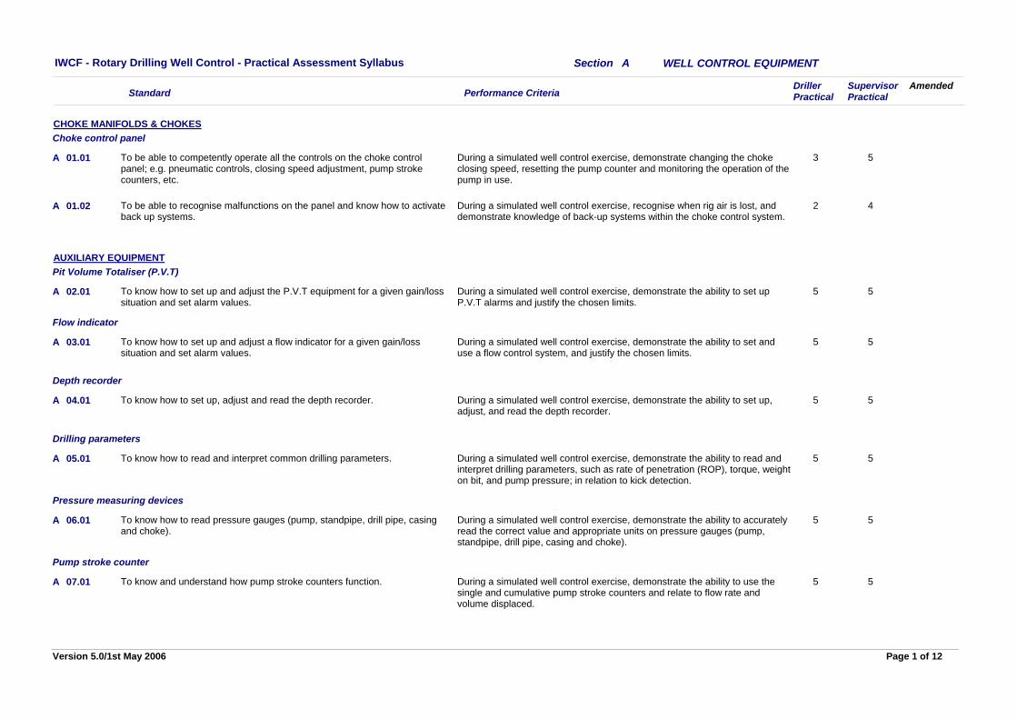
During a simulated well control exercise, demonstrate changing the choke closing speed, resetting the pump counter and monitoring the operation of the pump in use.
3 5To be able to competently operate all the controls on the choke control panel; e.g. pneumatic controls, closing speed adjustment, pump stroke counters, etc.
01.01
CHOKE MANIFOLDS & CHOKESChoke control panel
A
During a simulated well control exercise, recognise when rig air is lost, and demonstrate knowledge of back-up systems within the choke control system.
2 4To be able to recognise malfunctions on the panel and know how to activate back up systems.
01.02A
During a simulated well control exercise, demonstrate the ability to set up P.V.T alarms and justify the chosen limits.
5 5To know how to set up and adjust the P.V.T equipment for a given gain/loss situation and set alarm values.
02.01
AUXILIARY EQUIPMENTPit Volume Totaliser (P.V.T)
A
During a simulated well control exercise, demonstrate the ability to set and use a flow control system, and justify the chosen limits.
5 5To know how to set up and adjust a flow indicator for a given gain/loss situation and set alarm values.
03.01
Flow indicator
A
During a simulated well control exercise, demonstrate the ability to set up, adjust, and read the depth recorder.
5 5To know how to set up, adjust and read the depth recorder.04.01
Depth recorder
A
During a simulated well control exercise, demonstrate the ability to read and interpret drilling parameters, such as rate of penetration (ROP), torque, weight on bit, and pump pressure; in relation to kick detection.
5 5To know how to read and interpret common drilling parameters.05.01
Drilling parameters
A
During a simulated well control exercise, demonstrate the ability to accurately read the correct value and appropriate units on pressure gauges (pump, standpipe, drill pipe, casing and choke).
5 5To know how to read pressure gauges (pump, standpipe, drill pipe, casing and choke).
06.01
Pressure measuring devices
A
During a simulated well control exercise, demonstrate the ability to use the single and cumulative pump stroke counters and relate to flow rate and volume displaced.
5 5To know and understand how pump stroke counters function.07.01
Pump stroke counter
A
Page 1 of 12Version 5.0/1st May 2006
Performance CriteriaDrillerPractical
SupervisorPractical
IWCF - Rotary Drilling Well Control - Practical Assessment Syllabus
Standard
WELL CONTROL EQUIPMENT
Amended
Section A
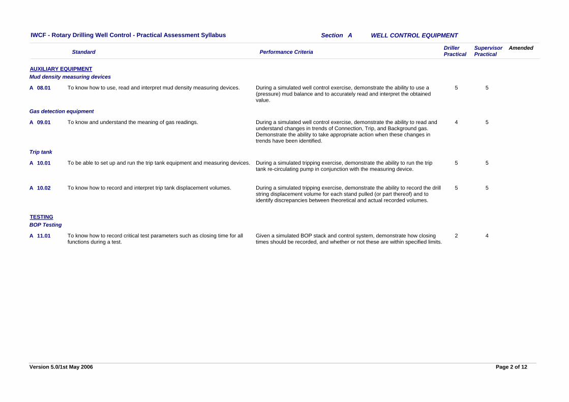
During a simulated well control exercise, demonstrate the ability to use a (pressure) mud balance and to accurately read and interpret the obtained value.
5 5To know how to use, read and interpret mud density measuring devices.08.01
AUXILIARY EQUIPMENTMud density measuring devices
A
During a simulated well control exercise, demonstrate the ability to read and understand changes in trends of Connection, Trip, and Background gas. Demonstrate the ability to take appropriate action when these changes in trends have been identified.
4 5To know and understand the meaning of gas readings.09.01
Gas detection equipment
A
During a simulated tripping exercise, demonstrate the ability to run the trip tank re-circulating pump in conjunction with the measuring device.
5 5To be able to set up and run the trip tank equipment and measuring devices.10.01
Trip tank
A
During a simulated tripping exercise, demonstrate the ability to record the drill string displacement volume for each stand pulled (or part thereof) and to identify discrepancies between theoretical and actual recorded volumes.
5 5To know how to record and interpret trip tank displacement volumes.10.02A
Given a simulated BOP stack and control system, demonstrate how closing times should be recorded, and whether or not these are within specified limits.
2 4To know how to record critical test parameters such as closing time for all functions during a test.
11.01
TESTINGBOP Testing
A
Page 2 of 12Version 5.0/1st May 2006
Performance CriteriaDrillerPractical
SupervisorPractical
IWCF - Rotary Drilling Well Control - Practical Assessment Syllabus
Standard
KILL SHEET INFORMATION
Amended
Section B
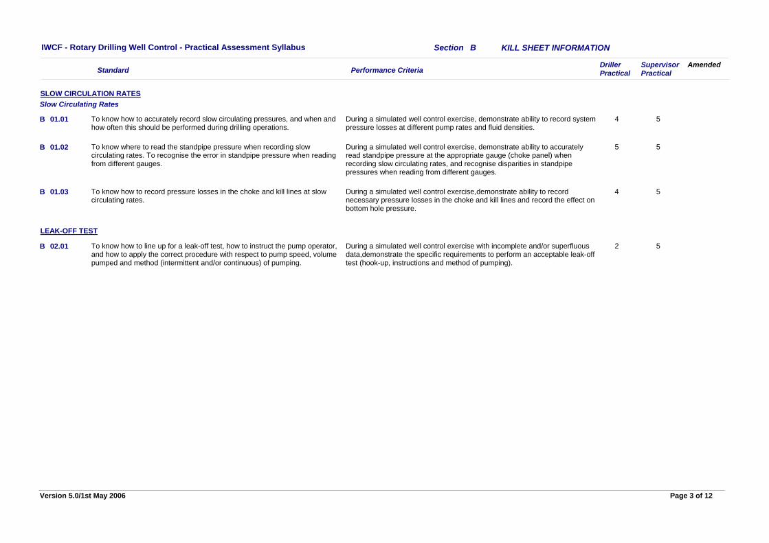
During a simulated well control exercise, demonstrate ability to record system pressure losses at different pump rates and fluid densities.
4 5To know how to accurately record slow circulating pressures, and when and how often this should be performed during drilling operations.
01.01
SLOW CIRCULATION RATESSlow Circulating Rates
B
During a simulated well control exercise, demonstrate ability to accurately read standpipe pressure at the appropriate gauge (choke panel) when recording slow circulating rates, and recognise disparities in standpipe pressures when reading from different gauges.
5 5To know where to read the standpipe pressure when recording slow circulating rates. To recognise the error in standpipe pressure when reading from different gauges.
01.02B
During a simulated well control exercise,demonstrate ability to record necessary pressure losses in the choke and kill lines and record the effect on bottom hole pressure.
4 5To know how to record pressure losses in the choke and kill lines at slow circulating rates.
01.03B
During a simulated well control exercise with incomplete and/or superfluous data,demonstrate the specific requirements to perform an acceptable leak-off test (hook-up, instructions and method of pumping).
2 5To know how to line up for a leak-off test, how to instruct the pump operator, and how to apply the correct procedure with respect to pump speed, volume pumped and method (intermittent and/or continuous) of pumping.
02.01
LEAK-OFF TEST
B
Page 3 of 12Version 5.0/1st May 2006
Performance CriteriaDrillerPractical
SupervisorPractical
IWCF - Rotary Drilling Well Control - Practical Assessment Syllabus
Standard
KICK INDICATORS
Amended
Section C
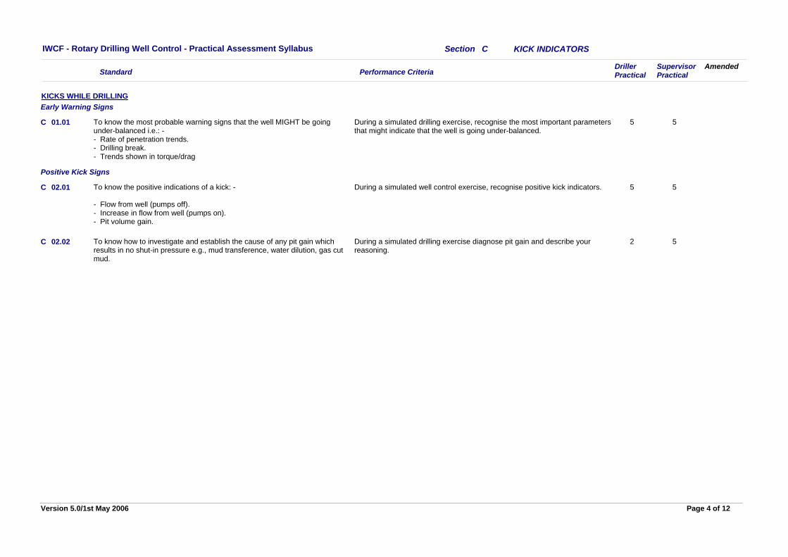
During a simulated drilling exercise, recognise the most important parameters that might indicate that the well is going under-balanced.
5 5To know the most probable warning signs that the well MIGHT be going under-balanced i.e.: -- Rate of penetration trends.- Drilling break.- Trends shown in torque/drag
01.01
KICKS WHILE DRILLINGEarly Warning Signs
C
During a simulated well control exercise, recognise positive kick indicators. 5 5To know the positive indications of a kick: -
- Flow from well (pumps off).- Increase in flow from well (pumps on).- Pit volume gain.
02.01
Positive Kick Signs
C
During a simulated drilling exercise diagnose pit gain and describe your reasoning.
2 5To know how to investigate and establish the cause of any pit gain which results in no shut-in pressure e.g., mud transference, water dilution, gas cut mud.
02.02C
Page 4 of 12Version 5.0/1st May 2006
Performance CriteriaDrillerPractical
SupervisorPractical
IWCF - Rotary Drilling Well Control - Practical Assessment Syllabus
Standard
SHUT IN PROCEDURES
Amended
Section D
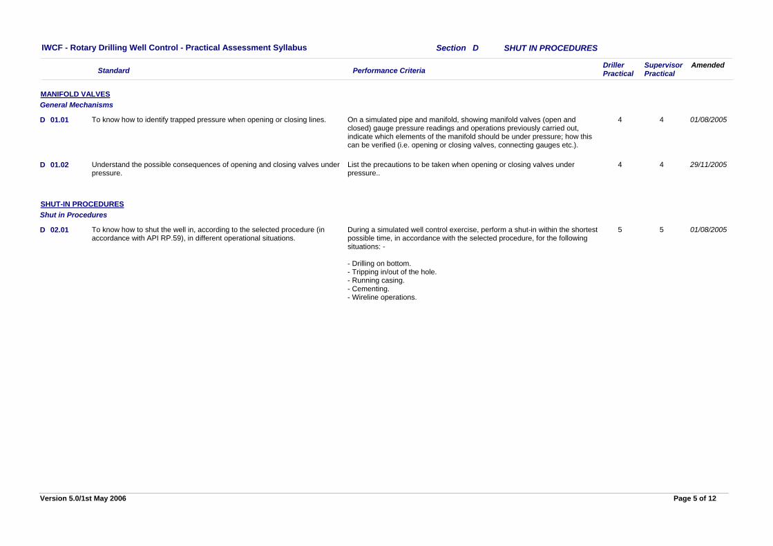
On a simulated pipe and manifold, showing manifold valves (open and closed) gauge pressure readings and operations previously carried out, indicate which elements of the manifold should be under pressure; how this can be verified (i.e. opening or closing valves, connecting gauges etc.).
4 4To know how to identify trapped pressure when opening or closing lines.01.01
MANIFOLD VALVESGeneral Mechanisms
01/08/2005D
List the precautions to be taken when opening or closing valves under pressure..
4 4Understand the possible consequences of opening and closing valves under pressure.
01.02 29/11/2005D
During a simulated well control exercise, perform a shut-in within the shortest possible time, in accordance with the selected procedure, for the following situations: -
- Drilling on bottom. - Tripping in/out of the hole. - Running casing. - Cementing. - Wireline operations.
5 5To know how to shut the well in, according to the selected procedure (in accordance with API RP.59), in different operational situations.
02.01
SHUT-IN PROCEDURESShut in Procedures
01/08/2005D
Page 5 of 12Version 5.0/1st May 2006
Performance CriteriaDrillerPractical
SupervisorPractical
IWCF - Rotary Drilling Well Control - Practical Assessment Syllabus
Standard
SHUT IN PRESSURES
Amended
Section E
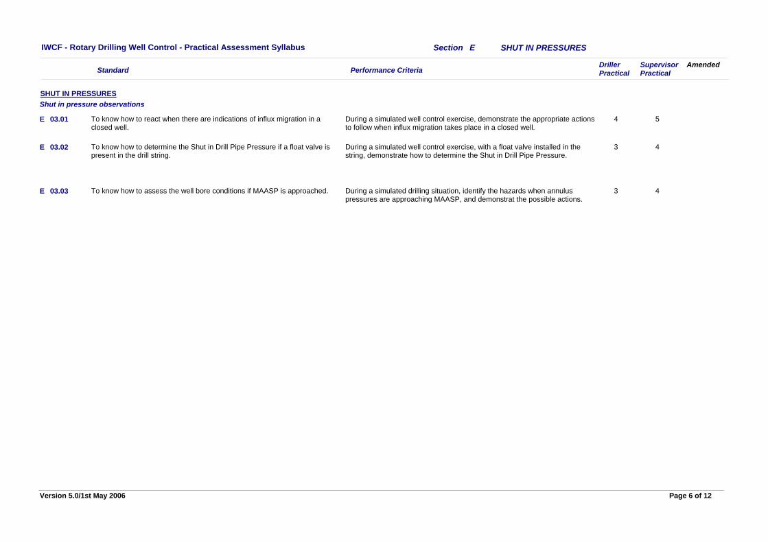
During a simulated well control exercise, demonstrate the appropriate actions to follow when influx migration takes place in a closed well.
4 5To know how to react when there are indications of influx migration in a closed well.
03.01
SHUT IN PRESSURESShut in pressure observations
E
During a simulated well control exercise, with a float valve installed in the string, demonstrate how to determine the Shut in Drill Pipe Pressure.
3 4To know how to determine the Shut in Drill Pipe Pressure if a float valve is present in the drill string.
03.02E
During a simulated drilling situation, identify the hazards when annulus pressures are approaching MAASP, and demonstrat the possible actions.
3 4To know how to assess the well bore conditions if MAASP is approached.03.03E
Page 6 of 12Version 5.0/1st May 2006
Performance CriteriaDrillerPractical
SupervisorPractical
IWCF - Rotary Drilling Well Control - Practical Assessment Syllabus
Standard
KILL METHODS
Amended
Section F
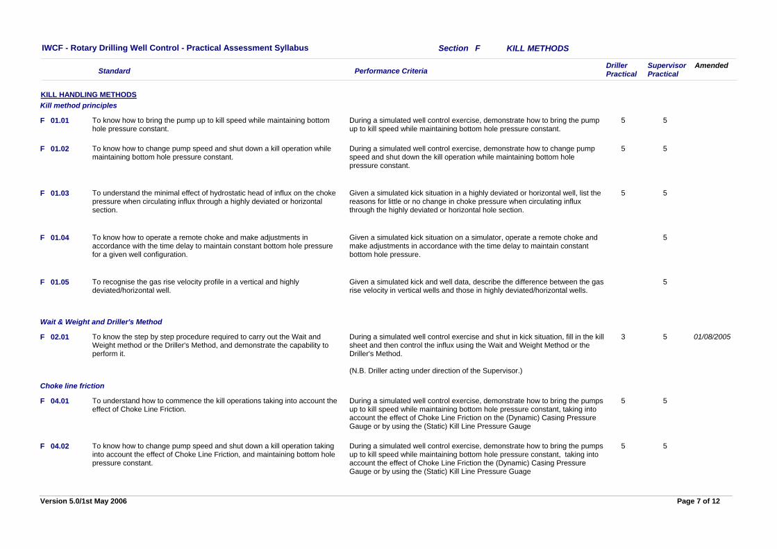
During a simulated well control exercise, demonstrate how to bring the pump up to kill speed while maintaining bottom hole pressure constant.
5 5To know how to bring the pump up to kill speed while maintaining bottom hole pressure constant.
01.01
KILL HANDLING METHODSKill method principles
F
During a simulated well control exercise, demonstrate how to change pump speed and shut down the kill operation while maintaining bottom hole pressure constant.
5 5To know how to change pump speed and shut down a kill operation while maintaining bottom hole pressure constant.
01.02F
Given a simulated kick situation in a highly deviated or horizontal well, list the reasons for little or no change in choke pressure when circulating influx through the highly deviated or horizontal hole section.
5 5To understand the minimal effect of hydrostatic head of influx on the choke pressure when circulating influx through a highly deviated or horizontal section.
01.03F
Given a simulated kick situation on a simulator, operate a remote choke and make adjustments in accordance with the time delay to maintain constant bottom hole pressure.
5To know how to operate a remote choke and make adjustments in accordance with the time delay to maintain constant bottom hole pressure for a given well configuration.
01.04F
Given a simulated kick and well data, describe the difference between the gas rise velocity in vertical wells and those in highly deviated/horizontal wells.
5To recognise the gas rise velocity profile in a vertical and highly deviated/horizontal well.
01.05F
During a simulated well control exercise and shut in kick situation, fill in the kill sheet and then control the influx using the Wait and Weight Method or the Driller's Method.
(N.B. Driller acting under direction of the Supervisor.)
3 5To know the step by step procedure required to carry out the Wait and Weight method or the Driller's Method, and demonstrate the capability to perform it.
02.01
Wait & Weight and Driller's Method
01/08/2005F
During a simulated well control exercise, demonstrate how to bring the pumps up to kill speed while maintaining bottom hole pressure constant, taking into account the effect of Choke Line Friction on the (Dynamic) Casing Pressure Gauge or by using the (Static) Kill Line Pressure Gauge
5 5To understand how to commence the kill operations taking into account the effect of Choke Line Friction.
04.01
Choke line friction
F
During a simulated well control exercise, demonstrate how to bring the pumps up to kill speed while maintaining bottom hole pressure constant, taking into account the effect of Choke Line Friction the (Dynamic) Casing Pressure Gauge or by using the (Static) Kill Line Pressure Guage
5 5To know how to change pump speed and shut down a kill operation taking into account the effect of Choke Line Friction, and maintaining bottom hole pressure constant.
04.02F
Page 7 of 12Version 5.0/1st May 2006
Performance CriteriaDrillerPractical
SupervisorPractical
IWCF - Rotary Drilling Well Control - Practical Assessment Syllabus
Standard
KILL METHODS
Amended
Section F
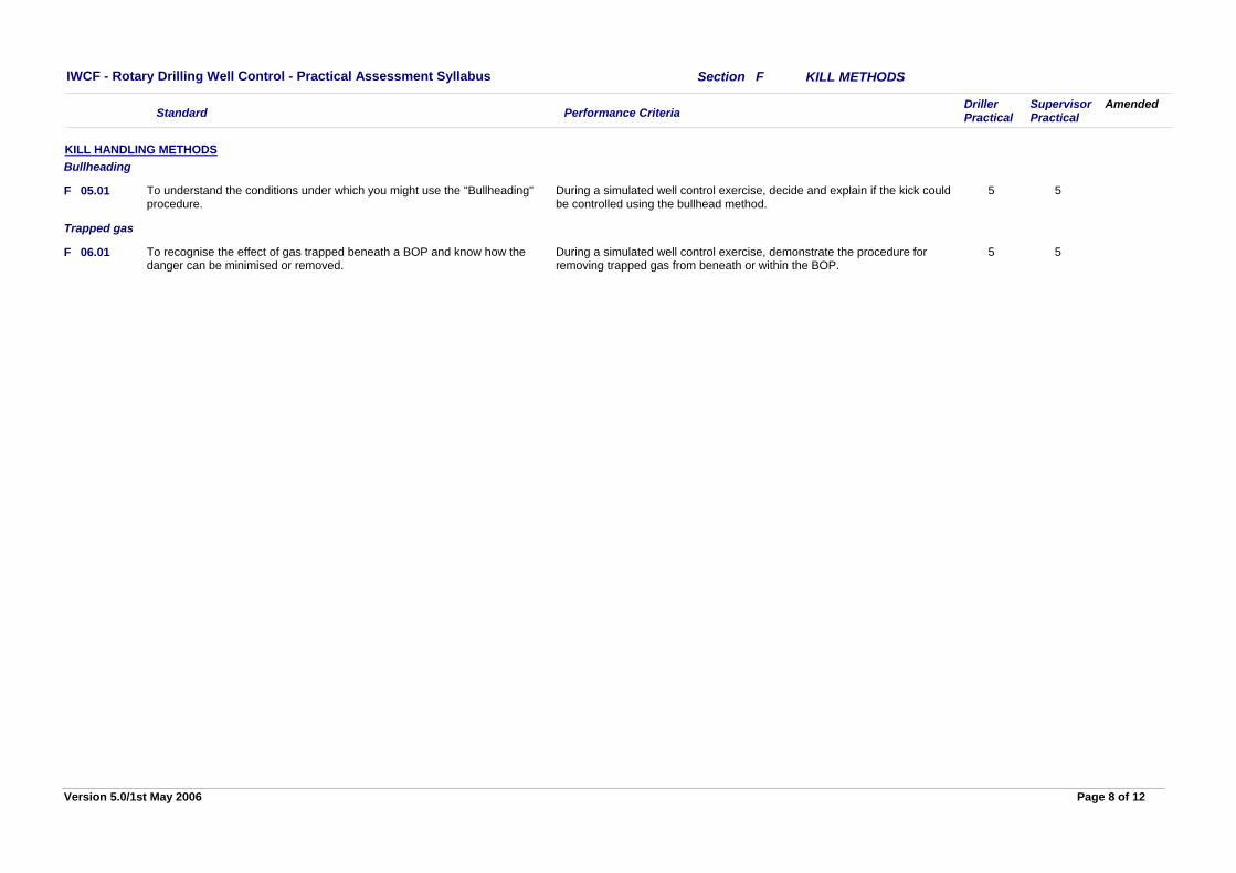
During a simulated well control exercise, decide and explain if the kick could be controlled using the bullhead method.
5 5To understand the conditions under which you might use the "Bullheading" procedure.
05.01
KILL HANDLING METHODSBullheading
F
During a simulated well control exercise, demonstrate the procedure for removing trapped gas from beneath or within the BOP.
5 5To recognise the effect of gas trapped beneath a BOP and know how the danger can be minimised or removed.
06.01
Trapped gas
F
Page 8 of 12Version 5.0/1st May 2006
Performance CriteriaDrillerPractical
SupervisorPractical
IWCF - Rotary Drilling Well Control - Practical Assessment Syllabus
Standard
KILL PROBLEMS
Amended
Section G
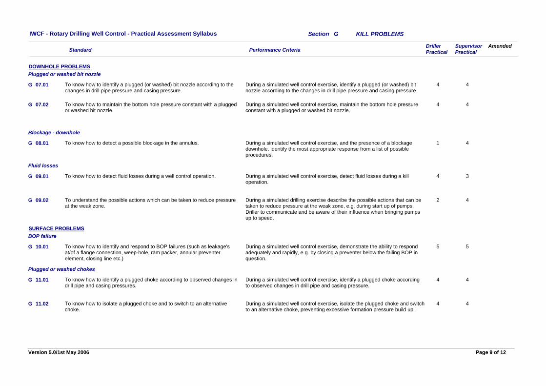
During a simulated well control exercise, identify a plugged (or washed) bit nozzle according to the changes in drill pipe pressure and casing pressure.
4 4To know how to identify a plugged (or washed) bit nozzle according to the changes in drill pipe pressure and casing pressure.
07.01
DOWNHOLE PROBLEMSPlugged or washed bit nozzle
G
During a simulated well control exercise, maintain the bottom hole pressure constant with a plugged or washed bit nozzle.
4 4To know how to maintain the bottom hole pressure constant with a plugged or washed bit nozzle.
07.02G
During a simulated well control exercise, and the presence of a blockage downhole, identify the most appropriate response from a list of possible procedures.
1 4To know how to detect a possible blockage in the annulus.08.01
Blockage - downhole
G
During a simulated well control exercise, detect fluid losses during a kill operation.
4 3To know how to detect fluid losses during a well control operation.09.01
Fluid losses
G
During a simulated drilling exercise describe the possible actions that can be taken to reduce pressure at the weak zone, e.g. during start up of pumps. Driller to communicate and be aware of their influence when bringing pumps up to speed.
2 4To understand the possible actions which can be taken to reduce pressure at the weak zone.
09.02G
During a simulated well control exercise, demonstrate the ability to respond adequately and rapidly, e.g. by closing a preventer below the failing BOP in question.
5 5To know how to identify and respond to BOP failures (such as leakage's at/of a flange connection, weep-hole, ram packer, annular preventer element, closing line etc.)
10.01
SURFACE PROBLEMSBOP failure
G
During a simulated well control exercise, identify a plugged choke according to observed changes in drill pipe and casing pressure.
4 4To know how to identify a plugged choke according to observed changes in drill pipe and casing pressures.
11.01
Plugged or washed chokes
G
During a simulated well control exercise, isolate the plugged choke and switch to an alternative choke, preventing excessive formation pressure build up.
4 4To know how to isolate a plugged choke and to switch to an alternative choke.
11.02G
Page 9 of 12Version 5.0/1st May 2006
Performance CriteriaDrillerPractical
SupervisorPractical
IWCF - Rotary Drilling Well Control - Practical Assessment Syllabus
Standard
KILL PROBLEMS
Amended
Section G
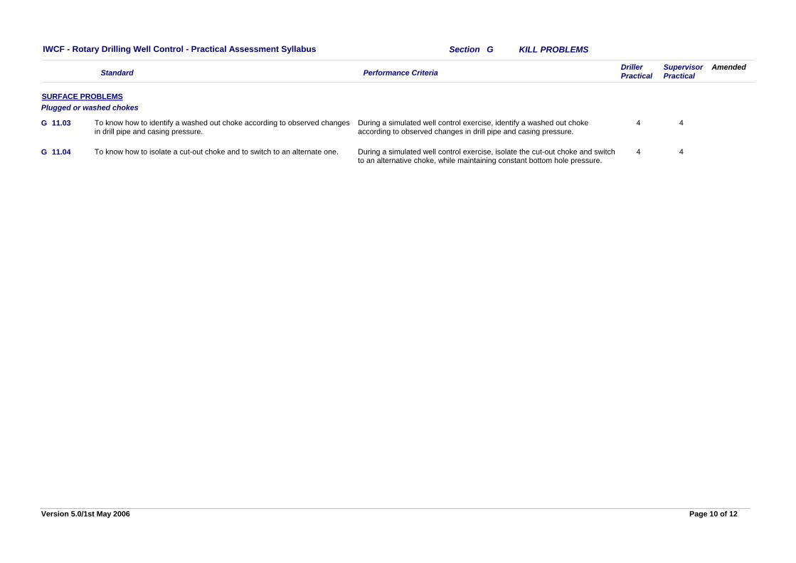
During a simulated well control exercise, identify a washed out choke according to observed changes in drill pipe and casing pressure.
4 4To know how to identify a washed out choke according to observed changes in drill pipe and casing pressure.
11.03
SURFACE PROBLEMSPlugged or washed chokes
G
During a simulated well control exercise, isolate the cut-out choke and switch to an alternative choke, while maintaining constant bottom hole pressure.
4 4To know how to isolate a cut-out choke and to switch to an alternate one.11.04G
Page 10 of 12Version 5.0/1st May 2006
Performance CriteriaDrillerPractical
SupervisorPractical
IWCF - Rotary Drilling Well Control - Practical Assessment Syllabus
Standard
WELL CONTROL MANAGEMENT
Amended
Section H
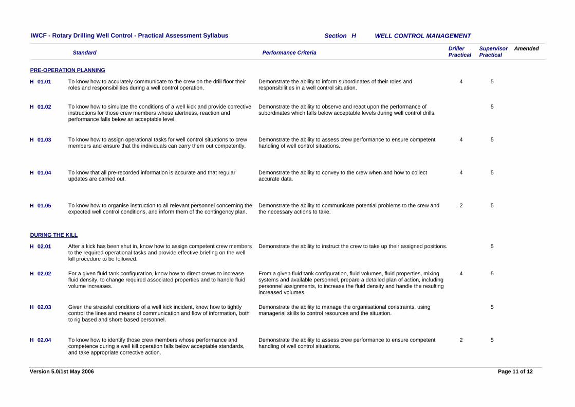
Demonstrate the ability to inform subordinates of their roles and responsibilities in a well control situation.
4 5To know how to accurately communicate to the crew on the drill floor their roles and responsibilities during a well control operation.
01.01
PRE-OPERATION PLANNING
H
Demonstrate the ability to observe and react upon the performance of subordinates which falls below acceptable levels during well control drills.
5To know how to simulate the conditions of a well kick and provide corrective instructions for those crew members whose alertness, reaction and performance falls below an acceptable level.
01.02H
Demonstrate the ability to assess crew performance to ensure competent handling of well control situations.
4 5To know how to assign operational tasks for well control situations to crew members and ensure that the individuals can carry them out competently.
01.03H
Demonstrate the ability to convey to the crew when and how to collect accurate data.
4 5To know that all pre-recorded information is accurate and that regular updates are carried out.
01.04H
Demonstrate the ability to communicate potential problems to the crew and the necessary actions to take.
2 5To know how to organise instruction to all relevant personnel concerning the expected well control conditions, and inform them of the contingency plan.
01.05H
Demonstrate the ability to instruct the crew to take up their assigned positions. 5After a kick has been shut in, know how to assign competent crew members to the required operational tasks and provide effective briefing on the well kill procedure to be followed.
02.01
DURING THE KILL
H
From a given fluid tank configuration, fluid volumes, fluid properties, mixing systems and available personnel, prepare a detailed plan of action, including personnel assignments, to increase the fluid density and handle the resulting increased volumes.
4 5For a given fluid tank configuration, know how to direct crews to increase fluid density, to change required associated properties and to handle fluid volume increases.
02.02H
Demonstrate the ability to manage the organisational constraints, using managerial skills to control resources and the situation.
5Given the stressful conditions of a well kick incident, know how to tightly control the lines and means of communication and flow of information, both to rig based and shore based personnel.
02.03H
Demonstrate the ability to assess crew performance to ensure competent handling of well control situations.
2 5To know how to identify those crew members whose performance and competence during a well kill operation falls below acceptable standards, and take appropriate corrective action.
02.04H
Page 11 of 12Version 5.0/1st May 2006
Performance CriteriaDrillerPractical
SupervisorPractical
IWCF - Rotary Drilling Well Control - Practical Assessment Syllabus
Standard
WELL CONTROL MANAGEMENT
Amended
Section H
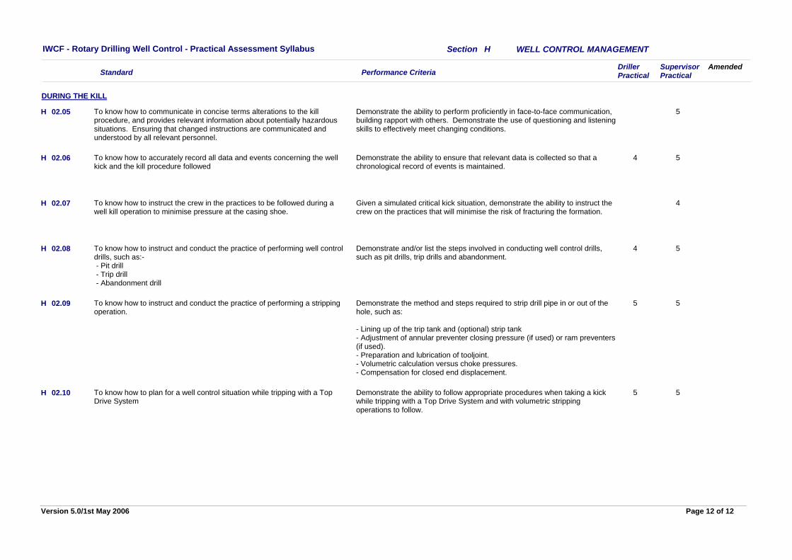
Demonstrate the ability to perform proficiently in face-to-face communication, building rapport with others. Demonstrate the use of questioning and listening skills to effectively meet changing conditions.
5To know how to communicate in concise terms alterations to the kill procedure, and provides relevant information about potentially hazardous situations. Ensuring that changed instructions are communicated and understood by all relevant personnel.
02.05
DURING THE KILL
H
Demonstrate the ability to ensure that relevant data is collected so that a chronological record of events is maintained.
4 5To know how to accurately record all data and events concerning the well kick and the kill procedure followed
02.06H
Given a simulated critical kick situation, demonstrate the ability to instruct the crew on the practices that will minimise the risk of fracturing the formation.
4To know how to instruct the crew in the practices to be followed during a well kill operation to minimise pressure at the casing shoe.
02.07H
Demonstrate and/or list the steps involved in conducting well control drills, such as pit drills, trip drills and abandonment.
4 5To know how to instruct and conduct the practice of performing well control drills, such as:- - Pit drill - Trip drill - Abandonment drill
02.08H
Demonstrate the method and steps required to strip drill pipe in or out of the hole, such as:
- Lining up of the trip tank and (optional) strip tank- Adjustment of annular preventer closing pressure (if used) or ram preventers (if used).- Preparation and lubrication of tooljoint.- Volumetric calculation versus choke pressures.- Compensation for closed end displacement.
5 5To know how to instruct and conduct the practice of performing a stripping operation.
02.09H
Demonstrate the ability to follow appropriate procedures when taking a kick while tripping with a Top Drive System and with volumetric stripping operations to follow.
5 5To know how to plan for a well control situation while tripping with a Top Drive System
02.10H
Page 12 of 12Version 5.0/1st May 2006
Performance Criteria Driller Supervisor
IWCF - Rotary Drilling Well Control - Written Test Syllabus
Standard
SURFACE BOP STACK, WELL CONTROL EQUIPMENT
Amended
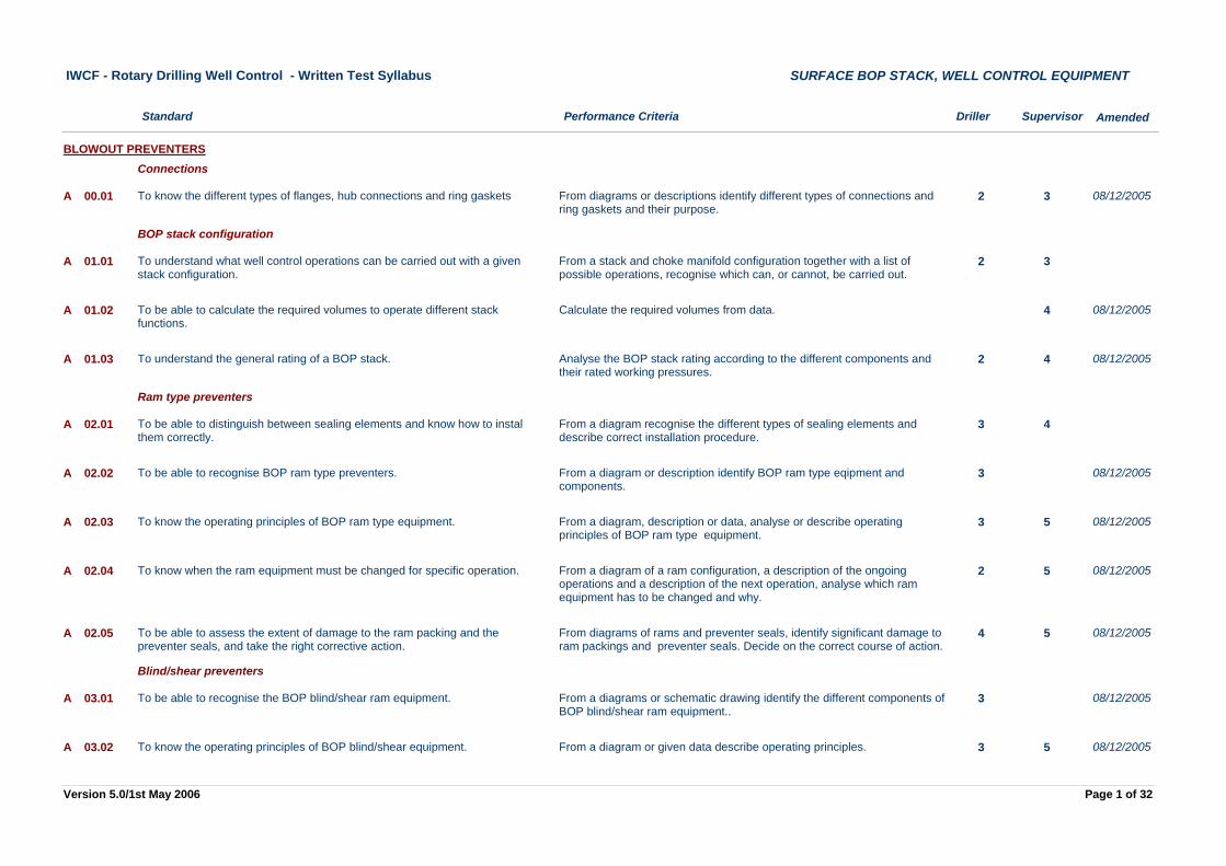
From diagrams or descriptions identify different types of connections and ring gaskets and their purpose.
2 3To know the different types of flanges, hub connections and ring gasketsA 00.01
BLOWOUT PREVENTERSConnections
08/12/2005
From a stack and choke manifold configuration together with a list of possible operations, recognise which can, or cannot, be carried out.
2 3To understand what well control operations can be carried out with a given stack configuration.
A 01.01
BOP stack configuration
Calculate the required volumes from data. 4To be able to calculate the required volumes to operate different stack functions.
A 01.02 08/12/2005
Analyse the BOP stack rating according to the different components and their rated working pressures.
2 4To understand the general rating of a BOP stack.A 01.03 08/12/2005
From a diagram recognise the different types of sealing elements and describe correct installation procedure.
3 4To be able to distinguish between sealing elements and know how to instal them correctly.
A 02.01
Ram type preventers
From a diagram or description identify BOP ram type eqipment and components.
3To be able to recognise BOP ram type preventers.A 02.02 08/12/2005
From a diagram, description or data, analyse or describe operating principles of BOP ram type equipment.
3 5To know the operating principles of BOP ram type equipment.A 02.03 08/12/2005
From a diagram of a ram configuration, a description of the ongoing operations and a description of the next operation, analyse which ram equipment has to be changed and why.
2 5To know when the ram equipment must be changed for specific operation.A 02.04 08/12/2005
From diagrams of rams and preventer seals, identify significant damage to ram packings and preventer seals. Decide on the correct course of action.
4 5To be able to assess the extent of damage to the ram packing and the preventer seals, and take the right corrective action.
A 02.05 08/12/2005
From a diagrams or schematic drawing identify the different components of BOP blind/shear ram equipment..
3To be able to recognise the BOP blind/shear ram equipment.A 03.01
Blind/shear preventers
08/12/2005
From a diagram or given data describe operating principles. 3 5To know the operating principles of BOP blind/shear equipment.A 03.02 08/12/2005
Page 1 of 32Version 5.0/1st May 2006
Performance Criteria Driller Supervisor
IWCF - Rotary Drilling Well Control - Written Test Syllabus
Standard
SURFACE BOP STACK, WELL CONTROL EQUIPMENT
Amended
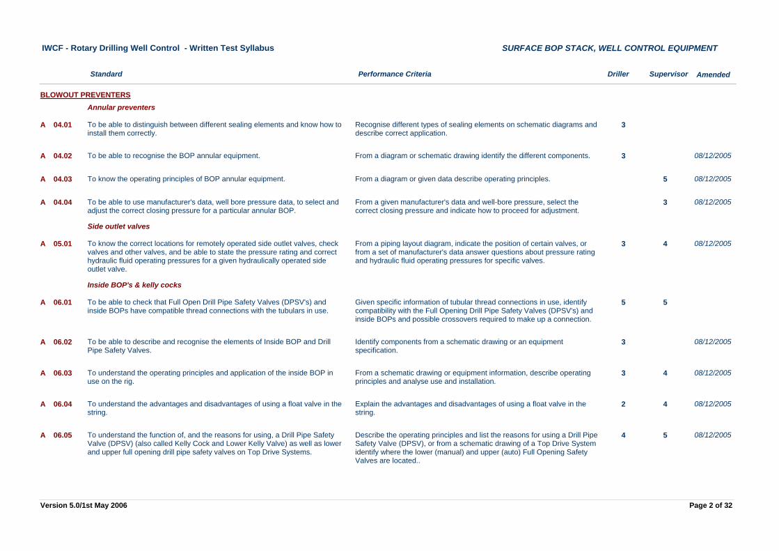
Recognise different types of sealing elements on schematic diagrams and describe correct application.
3To be able to distinguish between different sealing elements and know how to install them correctly.
A 04.01
BLOWOUT PREVENTERSAnnular preventers
From a diagram or schematic drawing identify the different components. 3To be able to recognise the BOP annular equipment.A 04.02 08/12/2005
From a diagram or given data describe operating principles. 5To know the operating principles of BOP annular equipment.A 04.03 08/12/2005
From a given manufacturer's data and well-bore pressure, select the correct closing pressure and indicate how to proceed for adjustment.
3To be able to use manufacturer's data, well bore pressure data, to select and adjust the correct closing pressure for a particular annular BOP.
A 04.04 08/12/2005
From a piping layout diagram, indicate the position of certain valves, or from a set of manufacturer's data answer questions about pressure rating and hydraulic fluid operating pressures for specific valves.
3 4To know the correct locations for remotely operated side outlet valves, check valves and other valves, and be able to state the pressure rating and correct hydraulic fluid operating pressures for a given hydraulically operated side outlet valve.
A 05.01
Side outlet valves
08/12/2005
Given specific information of tubular thread connections in use, identify compatibility with the Full Opening Drill Pipe Safety Valves (DPSV's) and inside BOPs and possible crossovers required to make up a connection.
5 5To be able to check that Full Open Drill Pipe Safety Valves (DPSV's) and inside BOPs have compatible thread connections with the tubulars in use.
A 06.01
Inside BOP's & kelly cocks
Identify components from a schematic drawing or an equipment specification.
3To be able to describe and recognise the elements of Inside BOP and Drill Pipe Safety Valves.
A 06.02 08/12/2005
From a schematic drawing or equipment information, describe operating principles and analyse use and installation.
3 4To understand the operating principles and application of the inside BOP in use on the rig.
A 06.03 08/12/2005
Explain the advantages and disadvantages of using a float valve in the string.
2 4To understand the advantages and disadvantages of using a float valve in the string.
A 06.04 08/12/2005
Describe the operating principles and list the reasons for using a Drill Pipe Safety Valve (DPSV), or from a schematic drawing of a Top Drive System identify where the lower (manual) and upper (auto) Full Opening Safety Valves are located..
4 5To understand the function of, and the reasons for using, a Drill Pipe Safety Valve (DPSV) (also called Kelly Cock and Lower Kelly Valve) as well as lower and upper full opening drill pipe safety valves on Top Drive Systems.
A 06.05 08/12/2005
Page 2 of 32Version 5.0/1st May 2006
Performance Criteria Driller Supervisor
IWCF - Rotary Drilling Well Control - Written Test Syllabus
Standard
SURFACE BOP STACK, WELL CONTROL EQUIPMENT
Amended
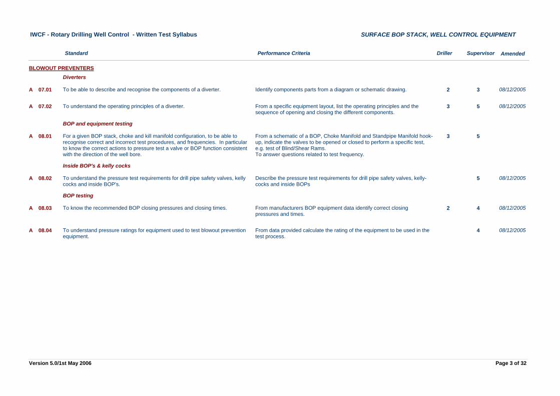
Identify components parts from a diagram or schematic drawing. 2 3To be able to describe and recognise the components of a diverter.A 07.01
BLOWOUT PREVENTERSDiverters
08/12/2005
From a specific equipment layout, list the operating principles and the sequence of opening and closing the different components.
3 5To understand the operating principles of a diverter.A 07.02 08/12/2005
From a schematic of a BOP, Choke Manifold and Standpipe Manifold hook-up, indicate the valves to be opened or closed to perform a specific test, e.g. test of Blind/Shear Rams.To answer questions related to test frequency.
3 5For a given BOP stack, choke and kill manifold configuration, to be able to recognise correct and incorrect test procedures, and frequencies. In particular to know the correct actions to pressure test a valve or BOP function consistent with the direction of the well bore.
A 08.01
BOP and equipment testing
Describe the pressure test requirements for drill pipe safety valves, kelly-cocks and inside BOPs
5To understand the pressure test requirements for drill pipe safety valves, kelly cocks and inside BOP's.
A 08.02
Inside BOP's & kelly cocks
08/12/2005
From manufacturers BOP equipment data identify correct closing pressures and times.
2 4To know the recommended BOP closing pressures and closing times.A 08.03
BOP testing
08/12/2005
From data provided calculate the rating of the equipment to be used in the test process.
4To understand pressure ratings for equipment used to test blowout prevention equipment.
A 08.04 08/12/2005
Page 3 of 32Version 5.0/1st May 2006
Performance Criteria Driller Supervisor
IWCF - Rotary Drilling Well Control - Written Test Syllabus
Standard
SURFACE BOP STACK, WELL CONTROL EQUIPMENT
Amended
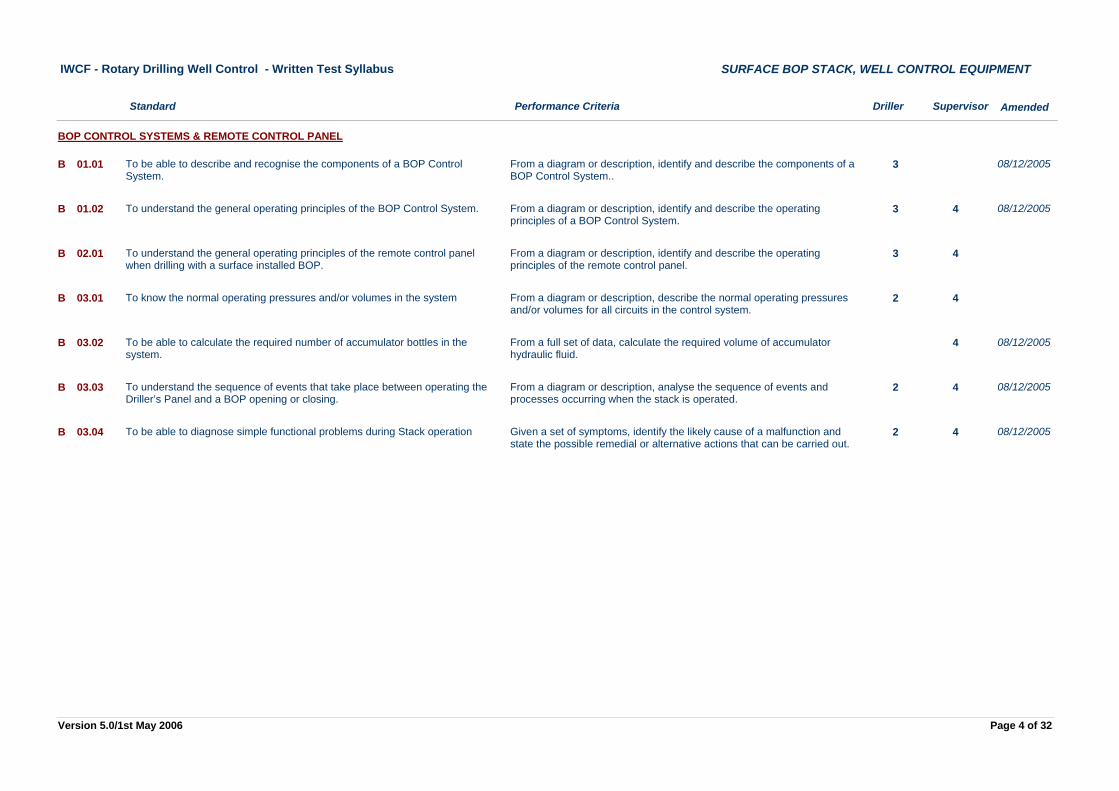
From a diagram or description, identify and describe the components of a BOP Control System..
3To be able to describe and recognise the components of a BOP Control System.
B 01.01
BOP CONTROL SYSTEMS & REMOTE CONTROL PANEL
08/12/2005
From a diagram or description, identify and describe the operating principles of a BOP Control System.
3 4To understand the general operating principles of the BOP Control System.B 01.02 08/12/2005
From a diagram or description, identify and describe the operating principles of the remote control panel.
3 4To understand the general operating principles of the remote control panel when drilling with a surface installed BOP.
B 02.01
From a diagram or description, describe the normal operating pressures and/or volumes for all circuits in the control system.
2 4To know the normal operating pressures and/or volumes in the systemB 03.01
From a full set of data, calculate the required volume of accumulator hydraulic fluid.
4To be able to calculate the required number of accumulator bottles in the system.
B 03.02 08/12/2005
From a diagram or description, analyse the sequence of events and processes occurring when the stack is operated.
2 4To understand the sequence of events that take place between operating the Driller’s Panel and a BOP opening or closing.
B 03.03 08/12/2005
Given a set of symptoms, identify the likely cause of a malfunction and state the possible remedial or alternative actions that can be carried out.
2 4To be able to diagnose simple functional problems during Stack operationB 03.04 08/12/2005
Page 4 of 32Version 5.0/1st May 2006
Performance Criteria Driller Supervisor
IWCF - Rotary Drilling Well Control - Written Test Syllabus
Standard
SURFACE BOP STACK, WELL CONTROL EQUIPMENT
Amended
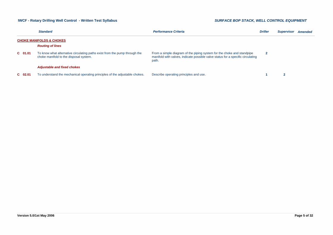
From a simple diagram of the piping system for the choke and standpipe manifold with valves, indicate possible valve status for a specific circulating path.
2To know what alternative circulating paths exist from the pump through the choke manifold to the disposal system.
C 01.01
CHOKE MANIFOLDS & CHOKESRouting of lines
Describe operating principles and use. 1 2To understand the mechanical operating principles of the adjustable chokes.C 02.01
Adjustable and fixed chokes
Page 5 of 32Version 5.0/1st May 2006
Performance Criteria Driller Supervisor
IWCF - Rotary Drilling Well Control - Written Test Syllabus
Standard
SURFACE BOP STACK, WELL CONTROL EQUIPMENT
Amended
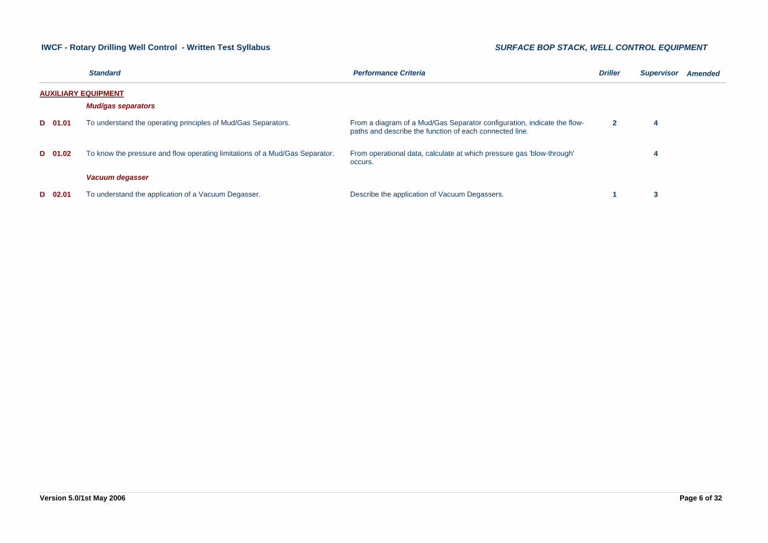
From a diagram of a Mud/Gas Separator configuration, indicate the flow-paths and describe the function of each connected line.
2 4To understand the operating principles of Mud/Gas Separators.D 01.01
AUXILIARY EQUIPMENTMud/gas separators
From operational data, calculate at which pressure gas 'blow-through' occurs.
4To know the pressure and flow operating limitations of a Mud/Gas Separator.D 01.02
Describe the application of Vacuum Degassers. 1 3To understand the application of a Vacuum Degasser.D 02.01
Vacuum degasser
Page 6 of 32Version 5.0/1st May 2006
Performance Criteria Driller Supervisor
IWCF - Rotary Drilling Well Control - Written Test Syllabus
Standard
SURFACE BOP STACK, PRE-RECORDED INFORMATION
Amended
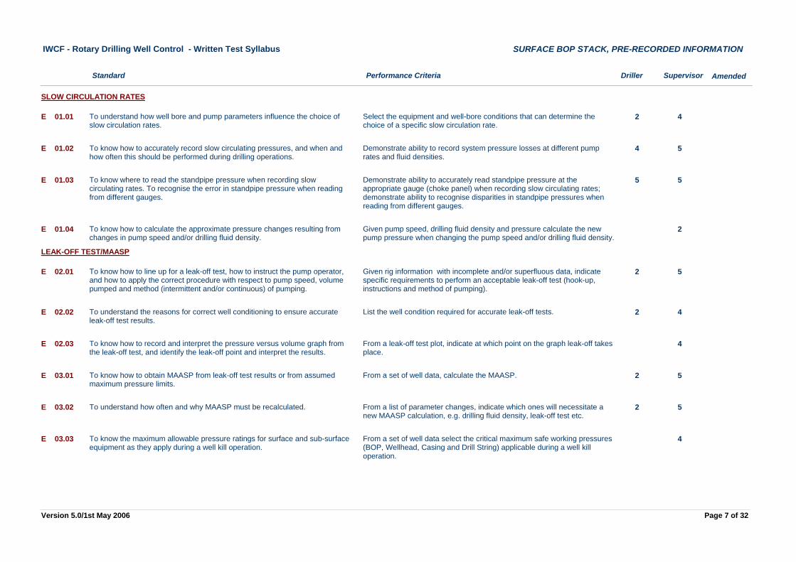
Select the equipment and well-bore conditions that can determine the choice of a specific slow circulation rate.
2 4To understand how well bore and pump parameters influence the choice of slow circulation rates.
E 01.01
SLOW CIRCULATION RATES
Demonstrate ability to record system pressure losses at different pump rates and fluid densities.
4 5To know how to accurately record slow circulating pressures, and when and how often this should be performed during drilling operations.
E 01.02
Demonstrate ability to accurately read standpipe pressure at the appropriate gauge (choke panel) when recording slow circulating rates; demonstrate ability to recognise disparities in standpipe pressures when reading from different gauges.
5 5To know where to read the standpipe pressure when recording slow circulating rates. To recognise the error in standpipe pressure when reading from different gauges.
E 01.03
Given pump speed, drilling fluid density and pressure calculate the new pump pressure when changing the pump speed and/or drilling fluid density.
2To know how to calculate the approximate pressure changes resulting from changes in pump speed and/or drilling fluid density.
E 01.04
Given rig information with incomplete and/or superfluous data, indicate specific requirements to perform an acceptable leak-off test (hook-up, instructions and method of pumping).
2 5To know how to line up for a leak-off test, how to instruct the pump operator, and how to apply the correct procedure with respect to pump speed, volume pumped and method (intermittent and/or continuous) of pumping.
E 02.01
LEAK-OFF TEST/MAASP
List the well condition required for accurate leak-off tests. 2 4To understand the reasons for correct well conditioning to ensure accurate leak-off test results.
E 02.02
From a leak-off test plot, indicate at which point on the graph leak-off takes place.
4To know how to record and interpret the pressure versus volume graph from the leak-off test, and identify the leak-off point and interpret the results.
E 02.03
From a set of well data, calculate the MAASP. 2 5To know how to obtain MAASP from leak-off test results or from assumed maximum pressure limits.
E 03.01
From a list of parameter changes, indicate which ones will necessitate a new MAASP calculation, e.g. drilling fluid density, leak-off test etc.
2 5To understand how often and why MAASP must be recalculated.E 03.02
From a set of well data select the critical maximum safe working pressures (BOP, Wellhead, Casing and Drill String) applicable during a well kill operation.
4To know the maximum allowable pressure ratings for surface and sub-surface equipment as they apply during a well kill operation.
E 03.03
Page 7 of 32Version 5.0/1st May 2006

Performance Criteria Driller Supervisor
IWCF - Rotary Drilling Well Control - Written Test Syllabus
Standard
SURFACE BOP STACK, CAUSES OF KICKS
Amended
Distinguish between 'Normal', 'Abnormal' and 'Overburden' pressures and list the main geological conditions that lead to abnormal formation pressures.
3To know the main geological conditions that can result in abnormal formation pressures..
F 01.01
NORMAL & ABNORMAL PRESSURES
Define the critical parameters when drilling top hole. 3 3To understand the means required to control critical drilling parameters when drilling top hole, to prevent a shallow gas influx, e.g. penetration rate, drilling fluid density, trip speed and pump rate.
F 02.01
TOP HOLE DRILLING
Compare top hole with deep hole drilling and note the differences in well control procedures and practices.
3 5To understand the difference between shallow and deep hole well control.F 02.02
Given well conditions with a reduction in drilling fluid density, recognise the appropriate reduction in hydrostatic head.
2 4To understand the effects on hydrostatic pressure when drilling through gas bearing formations.
F 03.01
GAS CUTTING
08/12/2005
From details of the well condition and drilling fluid density, calculate hydrostatic head at a specific depth.
4 4To know how to assess the possible effects of a drop in the level of drilling fluid in the annulus on the hydrostatic pressure required to balance formation pressure.
F 04.01
LOST CIRCULATION
From an example of total losses, determine the correct initial action to take. 3 3To know how to assess the actions to be taken in the event of a total loss of returns.
F 04.02
List the causes of surging and swabbing. 5 5To understand the causes of swabbing and surging in a well.F 05.01
KICKS AS A RESULT OF SURFACE INITIATED PRACTICESSwab And Surge Effects
Describe the consequences of surging and swabbing. 4 4To understand the effect of the following parameters on the magnitude of swab and surge pressures: - Well and pipe geometry - Well depth - Fluid characteristics - Hole conditions and formation properties - Tool pulling and running speeds- BHA configuration (stabilisers, packers etc.)- Horizontal reservoir sections
F 05.02
Page 8 of 32Version 5.0/1st May 2006
Performance Criteria Driller Supervisor
IWCF - Rotary Drilling Well Control - Written Test Syllabus
Standard
SURFACE BOP STACK, CAUSES OF KICKS
Amended
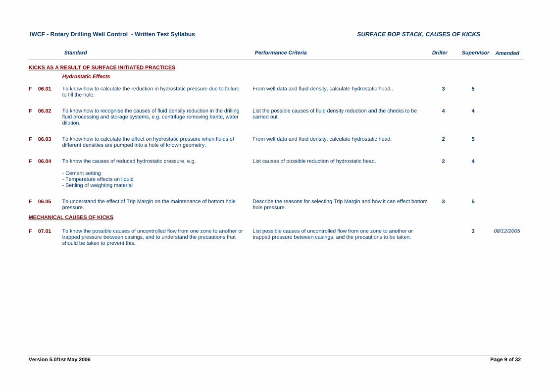
From well data and fluid density, calculate hydrostatic head.. 3 5To know how to calculate the reduction in hydrostatic pressure due to failure to fill the hole.
F 06.01
KICKS AS A RESULT OF SURFACE INITIATED PRACTICESHydrostatic Effects
List the possible causes of fluid density reduction and the checks to be carried out.
4 4To know how to recognise the causes of fluid density reduction in the drilling fluid processing and storage systems, e.g. centrifuge removing barite, water dilution.
F 06.02
From well data and fluid density, calculate hydrostatic head. 2 5To know how to calculate the effect on hydrostatic pressure when fluids of different densities are pumped into a hole of known geometry.
F 06.03
List causes of possible reduction of hydrostatic head. 2 4To know the causes of reduced hydrostatic pressure, e.g.
- Cement setting- Temperature effects on liquid- Settling of weighting material
F 06.04
Describe the reasons for selecting Trip Margin and how it can effect bottom hole pressure.
3 5To understand the effect of Trip Margin on the maintenance of bottom hole pressure.
F 06.05
List possible causes of uncontrolled flow from one zone to another or trapped pressure between casings, and the precautions to be taken.
3To know the possible causes of uncontrolled flow from one zone to another or trapped pressure between casings, and to understand the precautions that should be taken to prevent this.
F 07.01
MECHANICAL CAUSES OF KICKS
08/12/2005
Page 9 of 32Version 5.0/1st May 2006
Performance Criteria Driller Supervisor
IWCF - Rotary Drilling Well Control - Written Test Syllabus
Standard
SURFACE BOP STACK, KICK INDICATORS
Amended
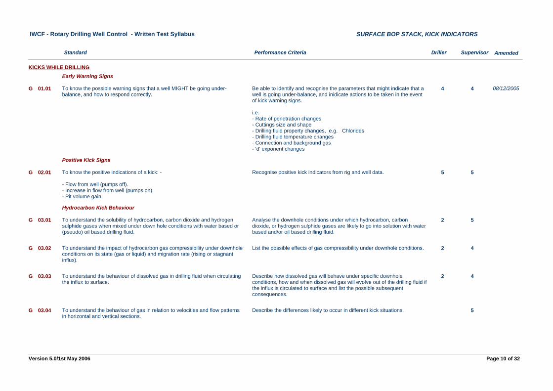
Be able to identify and recognise the parameters that might indicate that a well is going under-balance, and inidicate actions to be taken in the event of kick warning signs.
i.e.- Rate of penetration changes- Cuttings size and shape- Drilling fluid property changes, e.g. Chlorides- Drilling fluid temperature changes- Connection and background gas- 'd' exponent changes
4 4To know the possible warning signs that a well MIGHT be going under-balance, and how to respond correctly.
G 01.01
KICKS WHILE DRILLINGEarly Warning Signs
08/12/2005
Recognise positive kick indicators from rig and well data. 5 5To know the positive indications of a kick: -
- Flow from well (pumps off).- Increase in flow from well (pumps on).- Pit volume gain.
G 02.01
Positive Kick Signs
Analyse the downhole conditions under which hydrocarbon, carbon dioxide, or hydrogen sulphide gases are likely to go into solution with water based and/or oil based drilling fluid.
2 5To understand the solubility of hydrocarbon, carbon dioxide and hydrogen sulphide gases when mixed under down hole conditions with water based or (pseudo) oil based drilling fluid.
G 03.01
Hydrocarbon Kick Behaviour
List the possible effects of gas compressibility under downhole conditions. 2 4To understand the impact of hydrocarbon gas compressibility under downhole conditions on its state (gas or liquid) and migration rate (rising or stagnant influx).
G 03.02
Describe how dissolved gas will behave under specific downhole conditions, how and when dissolved gas will evolve out of the drilling fluid if the influx is circulated to surface and list the possible subsequent consequences.
2 4To understand the behaviour of dissolved gas in drilling fluid when circulating the influx to surface.
G 03.03
Describe the differences likely to occur in different kick situations. 5To understand the behaviour of gas in relation to velocities and flow patterns in horizontal and vertical sections.
G 03.04
Page 10 of 32Version 5.0/1st May 2006
Performance Criteria Driller Supervisor
IWCF - Rotary Drilling Well Control - Written Test Syllabus
Standard
SURFACE BOP STACK, KICK INDICATORS
Amended
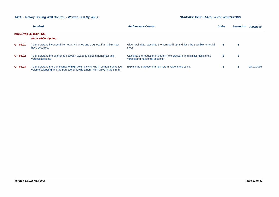
Given well data, calculate the correct fill up and describe possible remedial steps.
5 5To understand incorrect fill or return volumes and diagnose if an influx may have occurred.
G 04.01
KICKS WHILE TRIPPINGKicks while tripping
Calculate the reduction in bottom hole pressure from similar kicks in the vertical and horizontal sections.
5 5To understand the difference between swabbed kicks in horizontal and vertical sections.
G 04.02
Explain the purpose of a non-return valve in the string. 5 5To understand the significance of high volume swabbing in comparison to low volume swabbing and the purpose of having a non-return valve in the string.
G 04.03 08/12/2005
Page 11 of 32Version 5.0/1st May 2006
Performance Criteria Driller Supervisor
IWCF - Rotary Drilling Well Control - Written Test Syllabus
Standard
SURFACE BOP STACK, SHUT IN PROCEDURES
Amended
List the steps taken to shut a well in, in accordance with the hard or soft shut-in method, for the following situations:-
- Drilling on bottom.- Tripping in/out of the hole.- Running casing.- Cementing.- Wireline operations.
2 4To understand the steps taken to shut a well in using the hard or soft shut-in method (as described in API Recommended Practice No. 59), in different operational situations.
H 02.01
SHUT IN PROCEDURES
Page 12 of 32Version 5.0/1st May 2006
Performance Criteria Driller Supervisor
IWCF - Rotary Drilling Well Control - Written Test Syllabus
Standard
SURFACE BOP STACK, SHUT IN PRESSURES
Amended
Given a certain scale of a pressure gauge, indicate different pressure values on it, within the accuracy range.
2 4To know how a pressure gauge should be read and to recognise the accuracy depending on the range.
J 01.01
SHUT IN PRESSURESShut in pressure observations
From a schematic drawing of a standpipe and choke line systems with pressure gauges at different locations, explain the reason for different pressure readings (e.g. attach different values to certain gauges in the system).
2 4To understand the possible difference in pressure readings which can result from taking Shut in Drill Pipe Pressure and Shut in Casing Pressure at different gauges on the rig.
J 01.02
Describe the causes of pressure changes in a shut in well. 4 4To understand the possible causes for a pressure increase with time in a shut-in well.
J 01.03
Given a kick situation with well data, describe the appropriate actions to take when influx migration takes place in a closed well.
4 5To know how to react when there are indications of influx migration in a closed well.
J 01.04
Given a kick situation with well data, demonstrate how to determine the Shut in Drill Pipe Pressure with a float valve installed.
3 4To know how to determine the Shut in Drill Pipe Pressure if a float valve is present in the drill string.
J 01.05
Identify the hazards when annulus pressures are approaching MAASP and describe possible actions.
3 4To know how to assess the well bore conditions if MAASP is approached.J 01.06
List the reasons for having a kick and losses concurrently over a highly deviated or horizontal section.
3 5To understand the reasons for having a kick and losses concurrently over a highly deviated or horizontal section.
J 01.07
Given well and/or kick data, provide interpretation of the difference between Shut In Drill Pipe and Shut In Casing Pressure.
4To understand the possible reasons for differences between Shut In Drill Pipe (or String) Pressure and Shut In Casing (or Annulus) Pressure: -
· Influx density · Cuttings loading · Density of influx greater than drilling fluid · Position of bit and or pipe . Flow through the drill string . Blockage in the annulus . Inaccuracy of the guages . Well deviation
J 02.01
Shut in pressure interpretation
Page 13 of 32Version 5.0/1st May 2006
Performance Criteria Driller Supervisor
IWCF - Rotary Drilling Well Control - Written Test Syllabus
Standard
SURFACE BOP STACK, KILL METHODS
Amended
Describe the effects of different kill pump rates on formation strength, annular friction loss, mud/gas separator capacity, choke operator reaction time, baryte delivery time and pump safe valve settings.
4To know how to select kill pump rate consistent with the formation strength, annulus friction loss, mud/gas separator capacity, choke operator reaction time, baryte delivery time and pump safe valve settings.
K 01.01
KILL HANDLING METHODSKill method principles
Given a set of well bore conditions, but with the bit on bottom, select a kill method and explain the choice.
4To know how to select the most appropriate kill method with the bit on bottom.K 01.02
Given a set of well bore conditions, and while tripping or not on bottom, select and reason the safest course of action to be followed.
4To be able to select the most appropriate course of action when tripping or not on bottom.
K 01.03
Given well and kick data, demonstrate how to bring the pump up to kill speed while maintaining bottom hole pressure constant.
3 5To know how to bring the pump up to kill speed while maintaining bottom hole pressure constant.
K 01.04
Given well and kick data for a highly deviated or horizontal well, list the reasons for little or no change in choke pressure when circulating an influx through the highly deviated or horizontal hole section.
5 5To understand the minimal effect of hydrostatic head of influx on the choke pressure when circulating influx through a highly deviated or horizontal section.
K 01.05
Given well and kick data, shut down the kill operation while maintaining bottom hole pressure constant.
5 5To know how to change pump speeds and shut down a kill operation while maintaining bottom hole pressure constant.
K 01.06
Given well information or data. Analyse problems relating to the use of the Wait and Weight Method or Driller's Method to remove an influx from the well. (N.B. Driller acting under direction of the Supervisor.)
3 5To know the step by step procedure required to carry out the Wait and Weight method and the Driller's Method, demonstrating the capability to perform it.
K 02.01
Wait & Weight and Driller's Method
08/12/2005
Describe how the volumetric principle can be applied. 4To know the step-by-step procedure required for controlling a well according to the volumetric principle.
K 04.01
Volumetric method
List some situations when the volumetric principle should be applied. 4To understand when the volumetric principle is the appropriate well control technique.
K 04.02
List the step-by-step procedure of a stripping operation. 3 5To know the step-by-step procedure for a stripping operation.K 05.01
Stripping
Page 14 of 32Version 5.0/1st May 2006
Performance Criteria Driller Supervisor
IWCF - Rotary Drilling Well Control - Written Test Syllabus
Standard
SURFACE BOP STACK, KILL METHODS
Amended
Given well bore and rig equipment data, decide and explain if stripping back to bottom is possible.
4To know how to assess the suitability of stripping back to bottom given simulated well bore and rig equipment
K 05.02
KILL HANDLING METHODSStripping
Given well and kick data, describe the application when gunk and barite plugs are used.
4To know when gunk and barite plugs are used.K 06.01
Gunk and barite
List the step-by-step procedure to be followed by rig personnel when a shallow gas kick is in progress.
4 5To know the step-by-step procedure to be followed in order to secure the safety of the personnel and rig when a shallow gas kick is in progress.
K 07.01
Shallow gas
Page 15 of 32Version 5.0/1st May 2006
Performance Criteria Driller Supervisor
IWCF - Rotary Drilling Well Control - Written Test Syllabus
Standard
SURFACE BOP STACK, PERFORM CALCULATIONS
Amended
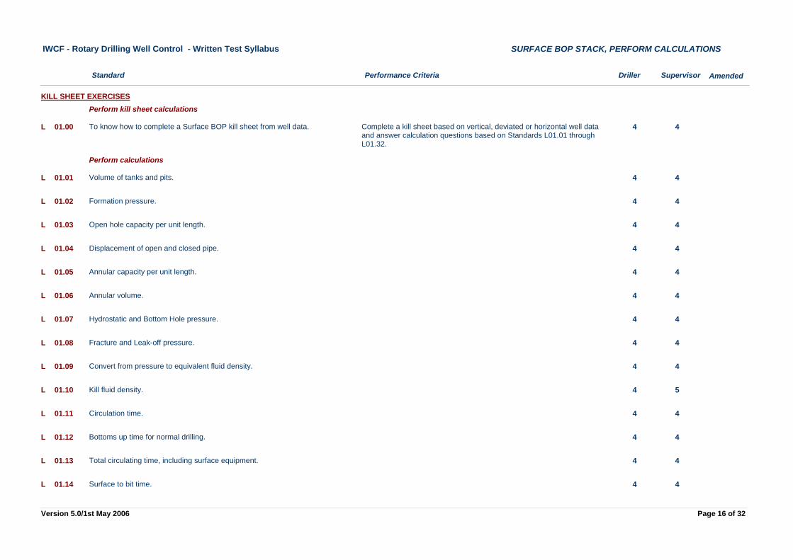
Complete a kill sheet based on vertical, deviated or horizontal well data and answer calculation questions based on Standards L01.01 through L01.32.
4 4To know how to complete a Surface BOP kill sheet from well data.L 01.00
KILL SHEET EXERCISESPerform kill sheet calculations
4 4Volume of tanks and pits.L 01.01
Perform calculations
4 4Formation pressure.L 01.02
4 4Open hole capacity per unit length.L 01.03
4 4Displacement of open and closed pipe.L 01.04
4 4Annular capacity per unit length.L 01.05
4 4Annular volume.L 01.06
4 4Hydrostatic and Bottom Hole pressure.L 01.07
4 4Fracture and Leak-off pressure.L 01.08
4 4Convert from pressure to equivalent fluid density.L 01.09
4 5Kill fluid density.L 01.10
4 4Circulation time.L 01.11
4 4Bottoms up time for normal drilling.L 01.12
4 4Total circulating time, including surface equipment.L 01.13
4 4Surface to bit time.L 01.14
Page 16 of 32Version 5.0/1st May 2006
Performance Criteria Driller Supervisor
IWCF - Rotary Drilling Well Control - Written Test Syllabus
Standard
SURFACE BOP STACK, PERFORM CALCULATIONS
Amended
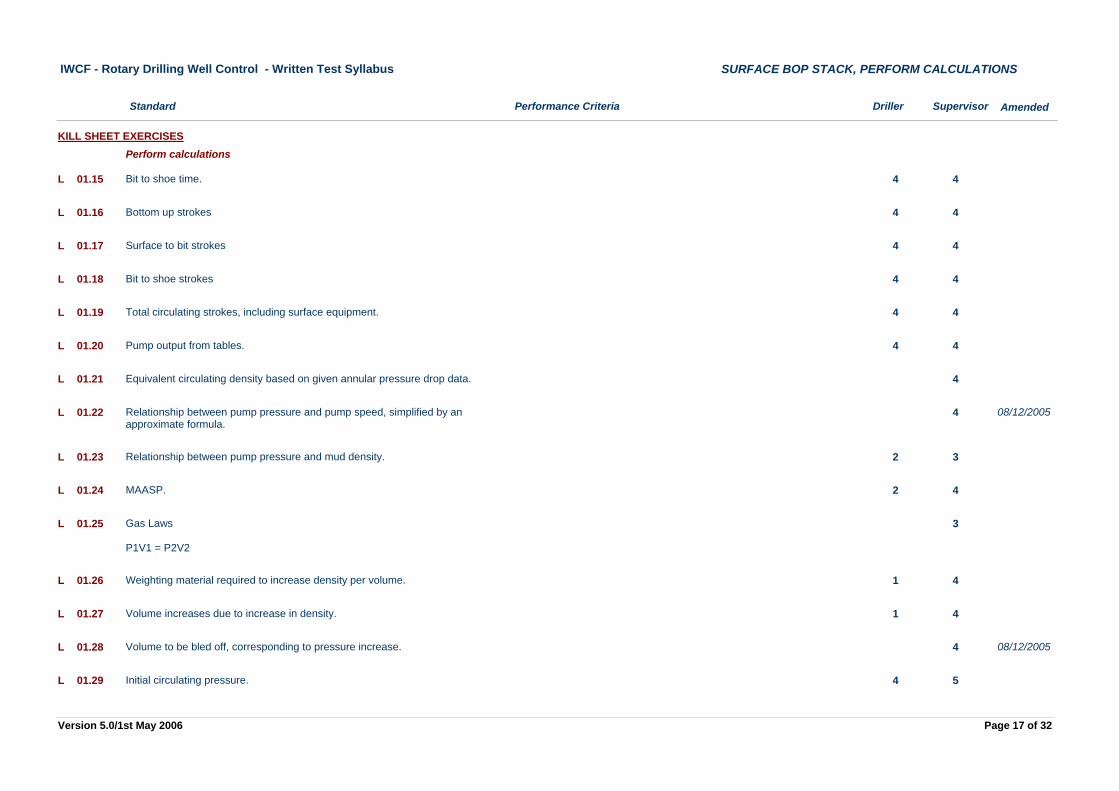
4 4Bit to shoe time.L 01.15
KILL SHEET EXERCISESPerform calculations
4 4Bottom up strokesL 01.16
4 4Surface to bit strokesL 01.17
4 4Bit to shoe strokesL 01.18
4 4Total circulating strokes, including surface equipment.L 01.19
4 4Pump output from tables.L 01.20
4Equivalent circulating density based on given annular pressure drop data.L 01.21
4Relationship between pump pressure and pump speed, simplified by an approximate formula.
L 01.22 08/12/2005
2 3Relationship between pump pressure and mud density.L 01.23
2 4MAASP.L 01.24
3Gas Laws
P1V1 = P2V2
L 01.25
1 4Weighting material required to increase density per volume.L 01.26
1 4Volume increases due to increase in density.L 01.27
4Volume to be bled off, corresponding to pressure increase.L 01.28 08/12/2005
4 5Initial circulating pressure.L 01.29
Page 17 of 32Version 5.0/1st May 2006
Performance Criteria Driller Supervisor
IWCF - Rotary Drilling Well Control - Written Test Syllabus
Standard
SURFACE BOP STACK, PERFORM CALCULATIONS
Amended
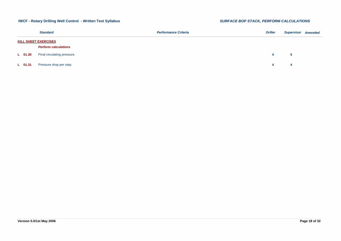
4 5Final circulating pressure.L 01.30
KILL SHEET EXERCISESPerform calculations
4 4Pressure drop per step.L 01.31
Page 18 of 32Version 5.0/1st May 2006
Performance Criteria Driller Supervisor
IWCF - Rotary Drilling Well Control - Written Test Syllabus
Standard
SURFACE BOP STACK, KILL PROBLEMS
Amended
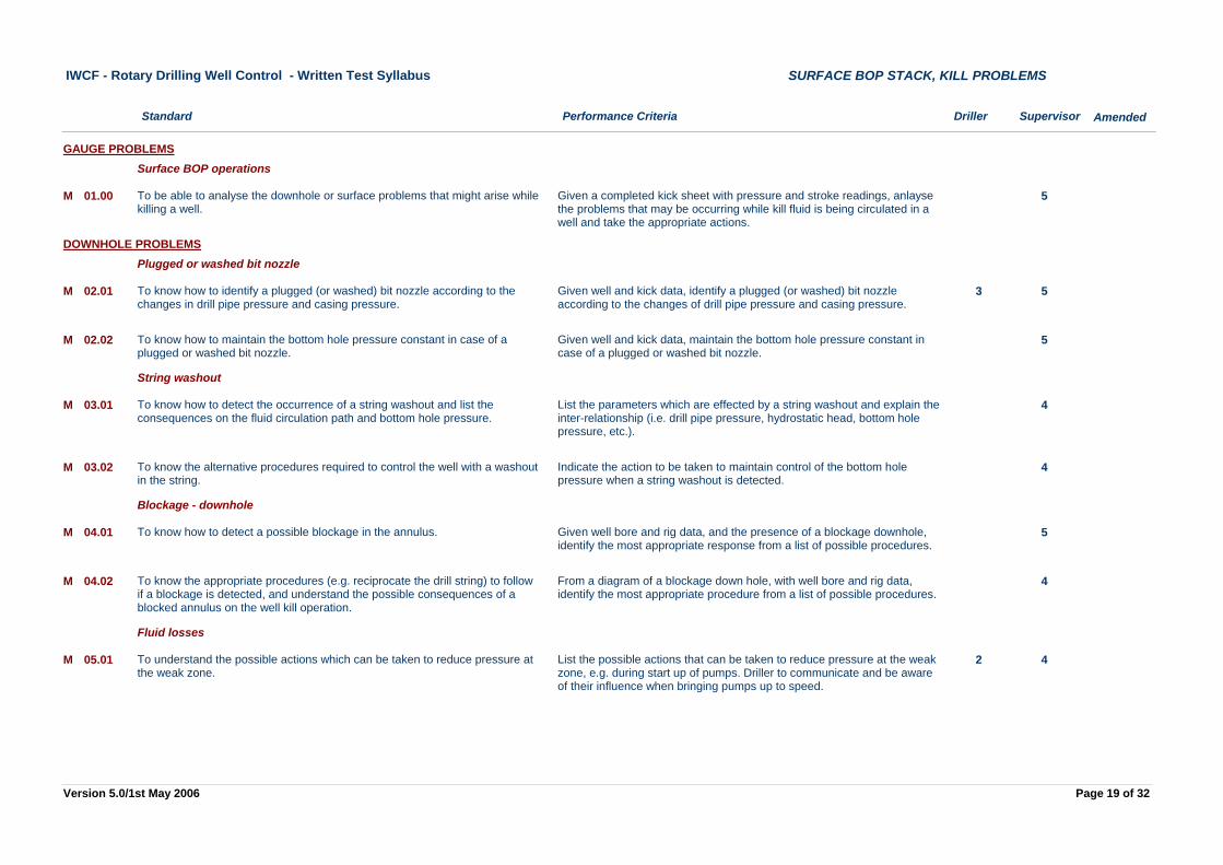
Given a completed kick sheet with pressure and stroke readings, anlayse the problems that may be occurring while kill fluid is being circulated in a well and take the appropriate actions.
5To be able to analyse the downhole or surface problems that might arise while killing a well.
M 01.00
GAUGE PROBLEMSSurface BOP operations
Given well and kick data, identify a plugged (or washed) bit nozzle according to the changes of drill pipe pressure and casing pressure.
3 5To know how to identify a plugged (or washed) bit nozzle according to the changes in drill pipe pressure and casing pressure.
M 02.01
DOWNHOLE PROBLEMSPlugged or washed bit nozzle
Given well and kick data, maintain the bottom hole pressure constant in case of a plugged or washed bit nozzle.
5To know how to maintain the bottom hole pressure constant in case of a plugged or washed bit nozzle.
M 02.02
List the parameters which are effected by a string washout and explain the inter-relationship (i.e. drill pipe pressure, hydrostatic head, bottom hole pressure, etc.).
4To know how to detect the occurrence of a string washout and list the consequences on the fluid circulation path and bottom hole pressure.
M 03.01
String washout
Indicate the action to be taken to maintain control of the bottom hole pressure when a string washout is detected.
4To know the alternative procedures required to control the well with a washout in the string.
M 03.02
Given well bore and rig data, and the presence of a blockage downhole, identify the most appropriate response from a list of possible procedures.
5To know how to detect a possible blockage in the annulus.M 04.01
Blockage - downhole
From a diagram of a blockage down hole, with well bore and rig data, identify the most appropriate procedure from a list of possible procedures.
4To know the appropriate procedures (e.g. reciprocate the drill string) to follow if a blockage is detected, and understand the possible consequences of a blocked annulus on the well kill operation.
M 04.02
List the possible actions that can be taken to reduce pressure at the weak zone, e.g. during start up of pumps. Driller to communicate and be aware of their influence when bringing pumps up to speed.
2 4To understand the possible actions which can be taken to reduce pressure at the weak zone.
M 05.01
Fluid losses
Page 19 of 32Version 5.0/1st May 2006
Performance Criteria Driller Supervisor
IWCF - Rotary Drilling Well Control - Written Test Syllabus
Standard
SURFACE BOP STACK, KILL PROBLEMS
Amended
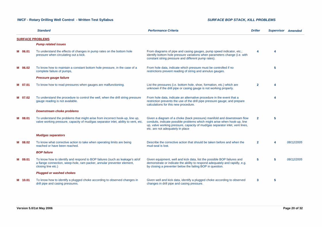
From diagrams of pipe and casing gauges, pump speed indicator, etc.; identify bottom hole pressure variations when parameters change (i.e. with constant string pressure and different pump rates).
4 4To understand the effects of changes in pump rates on the bottom hole pressure when circulating out a kick.
M 06.01
SURFACE PROBLEMSPump related issues
From hole data, indicate which pressure must be controlled if no restrictions prevent reading of string and annulus gauges.
5To know how to maintain a constant bottom hole pressure, in the case of a complete failure of pumps,
M 06.02
List the pressures (i.e. bottom hole, shoe, formation, etc.) which are unknown if the drill pipe or casing gauge is not working properly.
2 4To know how to read pressures when gauges are malfunctioning.M 07.01
Pressure gauge failure
From hole data, indicate an alternative procedure in the event that a restriction prevents the use of the drill pipe pressure gauge; and prepare calculations for this new procedure.
4To understand the procedure to control the well, when the drill string pressure gauge reading is not available.
M 07.02
Given a diagram of a choke (back pressure) manifold and downstream flow conduits, indicate possible problems which might arise when hook-up, line up, valve working pressure, capacity of mud/gas separator inlet, vent lines, etc. are not adequately in place
2 5To understand the problems that might arise from incorrect hook-up, line up, valve working pressure, capacity of mud/gas separator inlet, ability to vent, etc.
M 08.01
Downstream choke problems
Describe the corrective action that should be taken before and when the mud-seal is lost.
2 4To know what corrective action to take when operating limits are being reached or have been reached.
M 08.02
Mud/gas separators
08/12/2005
Given equipment, well and kick data, list the possible BOP failures and demonstrate or indicate the ability to respond adequately and rapidly, e.g. by closing a preventer below the failing BOP in question.
5 5To know how to identify and respond to BOP failures (such as leakage's at/of a flange connection, weep-hole, ram packer, annular preventer element, closing line etc.)
M 09.01
BOP failure
08/12/2005
Given well and kick data, identify a plugged choke according to observed changes in drill pipe and casing pressure.
3 5To know how to identify a plugged choke according to observed changes in drill pipe and casing pressures.
M 10.01
Plugged or washed chokes
Page 20 of 32Version 5.0/1st May 2006
Performance Criteria Driller Supervisor
IWCF - Rotary Drilling Well Control - Written Test Syllabus
Standard
SURFACE BOP STACK, KILL PROBLEMS
Amended
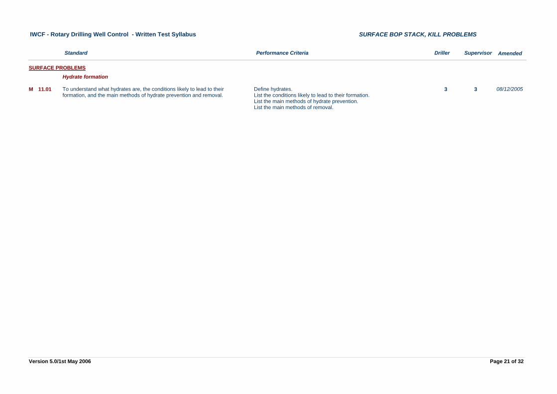
Define hydrates.List the conditions likely to lead to their formation.List the main methods of hydrate prevention.List the main methods of removal.
3 3To understand what hydrates are, the conditions likely to lead to their formation, and the main methods of hydrate prevention and removal.
M 11.01
SURFACE PROBLEMSHydrate formation
08/12/2005
Page 21 of 32Version 5.0/1st May 2006
Performance Criteria Driller Supervisor
IWCF - Rotary Drilling Well Control - Written Test Syllabus
Standard
SURFACE BOP STACK, WELL CONTROL MANAGEMENT
Amended
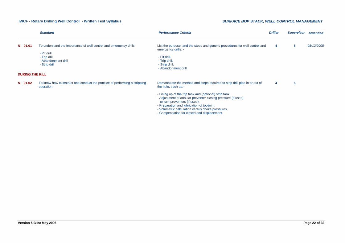
List the purpose, and the steps and generic procedures for well control and emergency drills: -
- Pit drill. - Trip drill. - Strip drill. - Abandonment drill.
4 5To understand the importance of well control and emergency drills.
- Pit drill - Trip drill - Abandonment drill - Strip drill
N 01.01 08/12/2005
Demonstrate the method and steps required to strip drill pipe in or out of the hole, such as:-
- Lining up of the trip tank and (optional) strip tank- Adjustment of annular preventer closing pressure (if used) or ram preventers (if used).- Preparation and lubrication of tooljoint.- Volumetric calculation versus choke pressures.- Compensation for closed end displacement.
4 5To know how to instruct and conduct the practice of performing a stripping operation.
N 01.02
DURING THE KILL
Page 22 of 32Version 5.0/1st May 2006
Performance Criteria Driller Supervisor
IWCF - Rotary Drilling Well Control - Written Test Syllabus
Standard
SUBSEA BOP STACK, WELL CONTROL EQUIPMENT
Amended
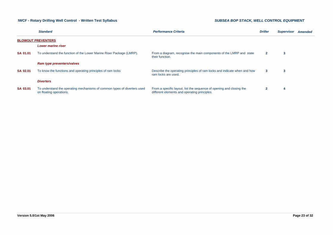
From a diagram, recognise the main components of the LMRP and state their function.
2 3To understand the function of the Lower Marine Riser Package (LMRP).SA 01.01
BLOWOUT PREVENTERSLower marine riser
Describe the operating principles of ram locks and indicate when and how ram locks are used.
3 3To know the functions and operating principles of ram locksSA 02.01
Ram type preventers/valves
From a specific layout, list the sequence of opening and closing the different elements and operating principles.
2 4To understand the operating mechanisms of common types of diverters used on floating operations.
SA 03.01
Diverters
Page 23 of 32Version 5.0/1st May 2006
Performance Criteria Driller Supervisor
IWCF - Rotary Drilling Well Control - Written Test Syllabus
Standard
SUBSEA BOP STACK, WELL CONTROL EQUIPMENT
Amended
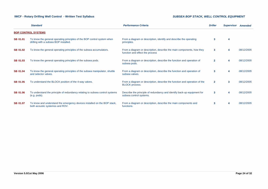
From a diagram or description, identify and describe the operating principles.
3 4To know the general operating principles of the BOP control system when drilling with a subsea BOP installed.
SB 01.01
BOP CONTROL SYSTEMS
From a diagram or description, describe the main components, how they function and effect the process
3 4To know the general operating principles of the subsea accumulators.SB 01.02 08/12/2005
From a diagram or description, describe the function and operation of subsea pods.
2 4To know the general operating principles of the subsea pods.SB 01.03 08/12/2005
From a diagram or description, describe the function and operation of subsea valves.
3 4To know the general operating principles of the subsea manipulator, shuttle and selector valves.
SB 01.04 08/12/2005
From a diagram or description, describe the function and operation of the BLOCK process.
2 3To understand the BLOCK position of the 4-way valves.SB 01.05 08/12/2005
Describe the principle of redundancy and identify back-up equipment for subsea control systems.
3 4To understand the principle of redundancy relating to subsea control systems (e.g. pods).
SB 01.06 08/12/2005
From a diagram or description, describe the main components and functions.
3 4To know and understand the emergency devices installed on the BOP stack, both acoustic systemss and ROV.
SB 01.07 08/12/2005
Page 24 of 32Version 5.0/1st May 2006
Performance Criteria Driller Supervisor
IWCF - Rotary Drilling Well Control - Written Test Syllabus
Standard
SUBSEA BOP STACK, WELL CONTROL EQUIPMENT
Amended
From a BOP stack diagram for a specific kill operation, select the appropriate line-up of choke lines; kill lines and valves upstream and downstream of chokes.
2 3To know the different stack line-ups during the kill operation.SC 01.01
CHOKE MANIFOLDS, CHOKES AND KILL LINESRouting of lines
Page 25 of 32Version 5.0/1st May 2006
Performance Criteria Driller Supervisor
IWCF - Rotary Drilling Well Control - Written Test Syllabus
Standard
SUBSEA BOP STACK, PRE-RECORDED INFORMATION
Amended
Demonstrate ability to record or analyse pressure losses in the choke and kill lines and determine the effect on bottom hole pressure.
4 5To know how to record pressure losses in the choke and kill lines at slow circulating rates when drilling with a subsea BOP stack.
SE 01.01
SLOW CIRCULATION RATES
Page 26 of 32Version 5.0/1st May 2006
Performance Criteria Driller Supervisor
IWCF - Rotary Drilling Well Control - Written Test Syllabus
Standard
SUBSEA BOP STACK, CAUSES OF KICKS
Amended
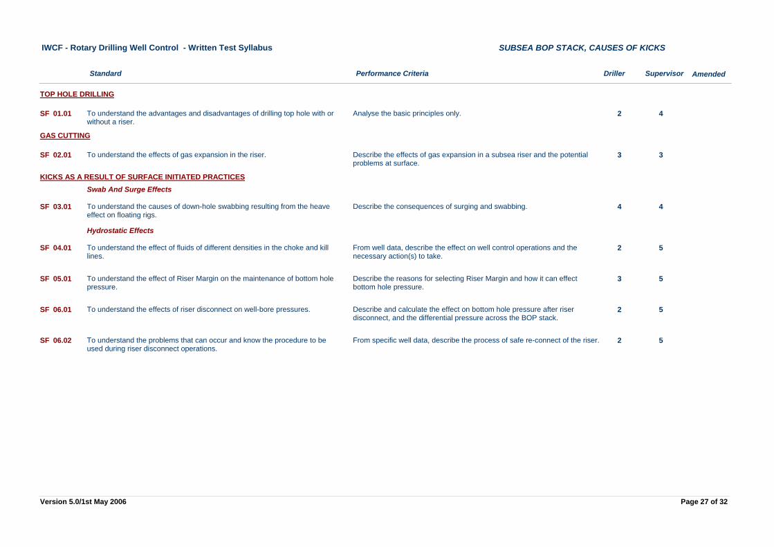
Analyse the basic principles only. 2 4To understand the advantages and disadvantages of drilling top hole with or without a riser.
SF 01.01
TOP HOLE DRILLING
Describe the effects of gas expansion in a subsea riser and the potential problems at surface.
3 3To understand the effects of gas expansion in the riser.SF 02.01
GAS CUTTING
Describe the consequences of surging and swabbing. 4 4To understand the causes of down-hole swabbing resulting from the heave effect on floating rigs.
SF 03.01
KICKS AS A RESULT OF SURFACE INITIATED PRACTICESSwab And Surge Effects
From well data, describe the effect on well control operations and the necessary action(s) to take.
2 5To understand the effect of fluids of different densities in the choke and kill lines.
SF 04.01
Hydrostatic Effects
Describe the reasons for selecting Riser Margin and how it can effect bottom hole pressure.
3 5To understand the effect of Riser Margin on the maintenance of bottom hole pressure.
SF 05.01
Describe and calculate the effect on bottom hole pressure after riser disconnect, and the differential pressure across the BOP stack.
2 5To understand the effects of riser disconnect on well-bore pressures.SF 06.01
From specific well data, describe the process of safe re-connect of the riser. 2 5To understand the problems that can occur and know the procedure to be used during riser disconnect operations.
SF 06.02
Page 27 of 32Version 5.0/1st May 2006
Performance Criteria Driller Supervisor
IWCF - Rotary Drilling Well Control - Written Test Syllabus
Standard
SUBSEA BOP STACK, KICK INDICATORS
Amended
List the problems associated with monitoring the well on a floating rig. 4 4To understand the effect of heave on pit level, flow rate and flow check monitoring.
SG 01.01
KICKS WHILE DRILLINGPositive Kick Signs
Page 28 of 32Version 5.0/1st May 2006
Performance Criteria Driller Supervisor
IWCF - Rotary Drilling Well Control - Written Test Syllabus
Standard
SUBSEA BOP STACK, SHUT IN PROCEDURES
Amended
List the steps taken to shut a well in, in accordance with the hard or soft shut-in method, for the following situations:-
- Drilling on bottom.- Tripping in/out of the hole.- Running casing.- Cementing.- Wireline operations.
2 4To understand the steps taken to shut a well in from a floating vessel using the hard or soft shut-in method (as described in API Recommended Practice No. 59), in different operational situations.
SH 01.01
SHUT IN PROCEDURES
Page 29 of 32Version 5.0/1st May 2006
Performance Criteria Driller Supervisor
IWCF - Rotary Drilling Well Control - Written Test Syllabus
Standard
SUBSEA BOP STACK, KILL METHODS
Amended
Given well and kick data, demonstrate how to bring the pumps up to kill speed while maintaining bottom hole pressure constantf. Take into account the effect of choke line friction on the (Dynamic) Casing Pressure Gauge or by using the (Static) Kill Line Pressure Gauge.
3 5To know the step by step procedure required to carry out the Driller's Method and the Wait and Weight method, and demonstrate the capability to perform them when drilling with a subsea BOP installed.
SK 01.01
KILL HANDLING METHODSWait & Weight and Driller's Method
08/12/2005
Given well and kick data, demonstrate how to bring the pumps up to kill speed while maintaining bottom hole pressure constant. By taking into account the effect of Choke Line Friction on the (Dynamic) Casing Pressure Gauge or by using the (Static) Kill Line Pressure Gauge
3 5To understand how to commence the kill operations taking into account the effect of Choke Line Friction.
SK 03.01
Choke line friction
Given well and kick data, demonstrate how to bring the pumps up to kill speed while maintaining bottom hole pressure constant. By taking into account the effect of Choke Line Friction the (Dynamic) Casing Pressure Gauge or by using the (Static) Kill Line Pressure Guage
3 5To know how to change pump speed and shut down a kill operation taking into account the effect of Choke Line Friction, and maintaining bottom hole pressure constant.
SK 03.02
Describe the procedure for displacing the Riser and Kill line following completion of Kill operations.
3 5To know how to displace Riser and Kill line prior to opening up the stack.SK 04.01
Riser & kill line displacement
Describe and demonstrate the procedure for removing trapped gas from beneath or within a BOP.
3 5To recognise the effect of gas trapped beneath a BOP and know how the danger can be minimised or removed.
SK 05.01
Trapped gas
Page 30 of 32Version 5.0/1st May 2006
Performance Criteria Driller Supervisor
IWCF - Rotary Drilling Well Control - Written Test Syllabus
Standard
SUBSEA BOP STACK, PERFORM CALCULATIONS
Amended
Complete a kill sheet based on vertical, deviated or horizontal well data and answer calculation questions based on Standards L01.01 through L01.32 plus Standards L02.01 through L02.06
4 4To know how to complete a Subsea BOP kill sheet from well data.SL 01.00
KILL SHEET EXERCISESPerform kill sheet calculations
2Effect of Water Depth on formation strength calculation.SL 01.01
Perform calculations
4 4Volume and fluid required to displace the Riser.SL 01.02
4 4Choke and kill line volumes.SL 01.03
4 4Choke and kill line strokes.SL 01.04
4 4Choke and kill line circulation time.SL 01.05
4 4Dynamic casing pressureSL 01.06
Page 31 of 32Version 5.0/1st May 2006
Performance Criteria Driller Supervisor
IWCF - Rotary Drilling Well Control - Written Test Syllabus
Standard
SUBSEA BOP STACK, KILL PROBLEMS
Amended
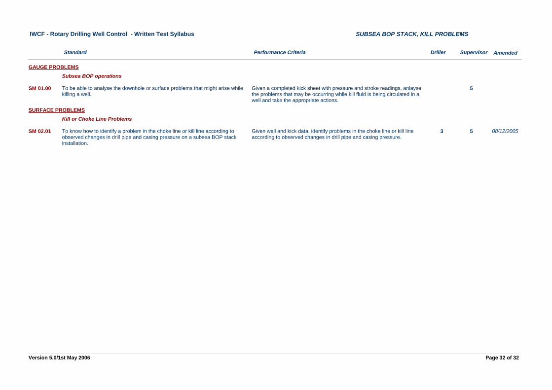
Given a completed kick sheet with pressure and stroke readings, anlayse the problems that may be occurring while kill fluid is being circulated in a well and take the appropriate actions.
5To be able to analyse the downhole or surface problems that might arise while killing a well.
SM 01.00
GAUGE PROBLEMSSubsea BOP operations
Given well and kick data, identify problems in the choke line or kill line according to observed changes in drill pipe and casing pressure.
3 5To know how to identify a problem in the choke line or kill line according to observed changes in drill pipe and casing pressure on a subsea BOP stack installation.
SM 02.01
SURFACE PROBLEMSKill or Choke Line Problems
08/12/2005
Page 32 of 32Version 5.0/1st May 2006