Embed Size (px)
Citation preview

OP
ER
AT
OR
'S M
AN
UA
L
ROTARY CUTTERM
AN
0390
(R
ev. 8
/30/
2013
)
DS96DS120

2 Introduction Gen’l (Rev. 3/28/2012)
TO THE DEALER:
Assembly and proper installation of this product is the responsibility of the Woods® dealer. Read manual instructionsand safety rules. Make sure all items on the Dealer’s Pre-Delivery and Delivery Check Lists in the Operator’s Manualare completed before releasing equipment to the owner.
The dealer must complete the online Product Registration form at the Woods Dealer Website which certifies thatall Dealer Check List items have been completed. Dealers can register all Woods product atdealer.WoodsEquipment.com under Product Registration.
Failure to register the product does not diminish customer’s warranty rights.
TO THE OWNER:
Read this manual before operating your Woods equipment. The information presented will prepare you to do a betterand safer job. Keep this manual handy for ready reference. Require all operators to read this manual carefully andbecome acquainted with all adjustment and operating procedures before attempting to operate. Replacement manualscan be obtained from your dealer. To locate your nearest dealer, check the Dealer Locator atwww.WoodsEquipment.com, or in the United States and Canada call 1-800-319-6637.
The equipment you have purchased has been carefully engineered and manufactured to provide dependable andsatisfactory use. Like all mechanical products, it will require cleaning and upkeep. Lubricate the unit as specified.Observe all safety information in this manual and safety decals on the equipment.
For service, your authorized Woods dealer has trained mechanics, genuine Woods service parts, and the necessarytools and equipment to handle all your needs.
Use only genuine Woods service parts. Substitute parts will void the warranty and may not meet standards required forsafe and satisfactory operation. Record the model number and serial number of your equipment in the spacesprovided:
Model: _______________________________ Date of Purchase: _____________________
Serial Number: (see Safety Decal section for location) ____________________________________
Provide this information to your dealer to obtain correct repair parts.
Throughout this manual, the term NOTICE is used to indicate that failure to observe can cause damage to equipment.The terms CAUTION, WARNING, and DANGER are used in conjunction with the Safety-Alert Symbol (a triangle withan exclamation mark) to indicate the degree of hazard for items of personal safety.
Introduction 3MAN0390 (Rev. 6/30/2006)
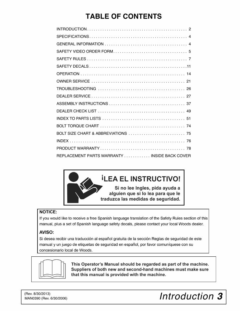
TABLE OF CONTENTS
INTRODUCTION . . . . . . . . . . . . . . . . . . . . . . . . . . . . . . . . . . . . . . . . . . . . . . 2
SPECIFICATIONS. . . . . . . . . . . . . . . . . . . . . . . . . . . . . . . . . . . . . . . . . . . . . 4
GENERAL INFORMATION . . . . . . . . . . . . . . . . . . . . . . . . . . . . . . . . . . . . . . 4
SAFETY VIDEO ORDER FORM. . . . . . . . . . . . . . . . . . . . . . . . . . . . . . . . . . 5
SAFETY RULES . . . . . . . . . . . . . . . . . . . . . . . . . . . . . . . . . . . . . . . . . . . . . . 7
SAFETY DECALS . . . . . . . . . . . . . . . . . . . . . . . . . . . . . . . . . . . . . . . . . . . . .11
OPERATION . . . . . . . . . . . . . . . . . . . . . . . . . . . . . . . . . . . . . . . . . . . . . . . . 14
OWNER SERVICE . . . . . . . . . . . . . . . . . . . . . . . . . . . . . . . . . . . . . . . . . . . 21
TROUBLESHOOTING . . . . . . . . . . . . . . . . . . . . . . . . . . . . . . . . . . . . . . . . 26
DEALER SERVICE . . . . . . . . . . . . . . . . . . . . . . . . . . . . . . . . . . . . . . . . . . . 27
ASSEMBLY INSTRUCTIONS . . . . . . . . . . . . . . . . . . . . . . . . . . . . . . . . . . . 37
DEALER CHECK LIST . . . . . . . . . . . . . . . . . . . . . . . . . . . . . . . . . . . . . . . . 49
INDEX TO PARTS LISTS . . . . . . . . . . . . . . . . . . . . . . . . . . . . . . . . . . . . . . 51
BOLT TORQUE CHART . . . . . . . . . . . . . . . . . . . . . . . . . . . . . . . . . . . . . . . 74
BOLT SIZE CHART & ABBREVIATIONS . . . . . . . . . . . . . . . . . . . . . . . . . . 75
INDEX . . . . . . . . . . . . . . . . . . . . . . . . . . . . . . . . . . . . . . . . . . . . . . . . . . . . . 76
PRODUCT WARRANTY . . . . . . . . . . . . . . . . . . . . . . . . . . . . . . . . . . . . . . . 78
REPLACEMENT PARTS WARRANTY . . . . . . . . . . . . INSIDE BACK COVER
(Rev. 8/30/2013)
4 Introduction MAN0390 (Rev. 6/30/2006)
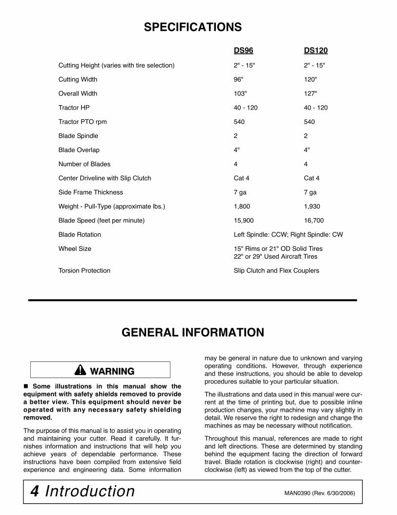
SPECIFICATIONS
DS96 DS120
Cutting Height (varies with tire selection) 2" - 15" 2" - 15"
Cutting Width 96" 120"
Overall Width 103" 127"
Tractor HP 40 - 120 40 - 120
Tractor PTO rpm 540 540
Blade Spindle 2 2
Blade Overlap 4" 4"
Number of Blades 4 4
Center Driveline with Slip Clutch Cat 4 Cat 4
Side Frame Thickness 7 ga 7 ga
Weight - Pull-Type (approximate lbs.) 1,800 1,930
Blade Speed (feet per minute) 15,900 16,700
Blade Rotation Left Spindle: CCW; Right Spindle: CW
Wheel Size 15" Rims or 21" OD Solid Tires22" or 29" Used Aircraft Tires
Torsion Protection Slip Clutch and Flex Couplers
GENERAL INFORMATION
Some illustrations in this manual show theequipment with safety shields removed to providea better view. This equipment should never beoperated with any necessary safety shieldingremoved.
The purpose of this manual is to assist you in operatingand maintaining your cutter. Read it carefully. It fur-nishes information and instructions that will help youachieve years of dependable performance. Theseinstructions have been compiled from extensive fieldexperience and engineering data. Some information
may be general in nature due to unknown and varyingoperating conditions. However, through experienceand these instructions, you should be able to developprocedures suitable to your particular situation.
The illustrations and data used in this manual were cur-rent at the time of printing but, due to possible inlineproduction changes, your machine may vary slightly indetail. We reserve the right to redesign and change themachines as may be necessary without notification.
Throughout this manual, references are made to rightand left directions. These are determined by standingbehind the equipment facing the direction of forwardtravel. Blade rotation is clockwise (right) and counter-clockwise (left) as viewed from the top of the cutter.
�������

Safety 5Safety Video Order Form (8/2/2005)
Free Mower Safety VideoFill out and return the order form and we will send you a FREE VHSor DVD video outlining Industrial and Agricultural Mower SafetyPractices. The 22 minute video, developed in cooperation withAEM (Association of Equipment Manufacturers), reinforces theproper procedures to follow while operating your mowingequipment. The video does not replace the information contained inthe Operator’s Manual, so please review this manual thoroughlybefore operating your new mowing equipment.
Safety Training Does Make a Difference.
BE SAFE!
BE ALERT!
BE ALIVE!
BE TRAINED Before Operating Mowers!
ASSOCIATION OF EQUIPMENT MANUFACTURERS
Safety Video Order Form
6 Safety Safety Video Order Form (Rev. 2/6/2006)
Free Mower/Cutter Safety Video Order Form
(Select one)
VHS Format - VHS01052 Safety Video
DVD Format - DVD01052 Safety Video Please send me
Name: ________________________________________ Phone: __________________
Address: _____________________________________
_____________________________________
_____________________________________
Mower/Cutter Model: ______________________ Serial #: ________________________
Send to: ATTENTION: DEALER SERVICESWOODS EQUIPMENT COMPANYPO BOX 1000OREGON IL 61061-1000USA
Also, available from the Association of Equipment Manufacturers:
A large variety of training materials (ideal for groups) are available for a nominal charge from AEM. Following is a partial list:
● Training Package for Rotary Mowers/Cutters-English Contains: DVD & VHS (English)
Guidebook for Rotary Mowers/Cutters (English)AEM Industrial/Agricultural Mower Safety Manual (English)AEM Agricultural Tractor Safety Manual (English)
● Training Package for Rotary Mowers/Cutters-English/Spanish Contains: DVD & VHS (English/Spanish)
Guidebook for Rotary Mowers/Cutters (English/Spanish)AEM Industrial/Agricultural Mower Safety Manual (English/Spanish)AEM Agricultural Tractor Safety Manual (English/Spanish)
AEM training packages are available through:
AEM at: www.aem.org
orUniversal Lithographers, Inc.Email: [email protected] tel866-541-1668 fax
Safety 7DS96-DS120 Safety Rules (Rev. 4/18/2012)
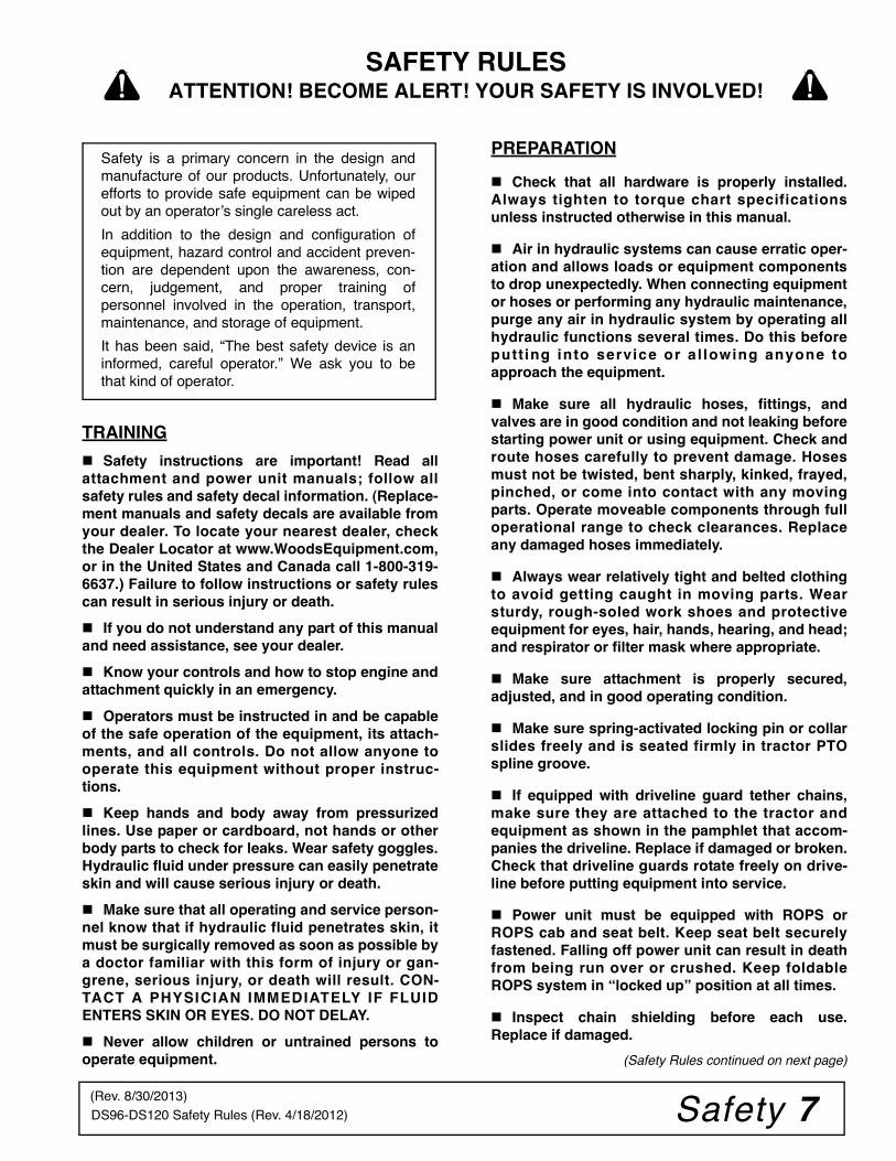
TRAINING
Safety instructions are important! Read allattachment and power unit manuals; follow allsafety rules and safety decal information. (Replace-ment manuals and safety decals are available fromyour dealer. To locate your nearest dealer, checkthe Dealer Locator at www.WoodsEquipment.com,or in the United States and Canada call 1-800-319-6637.) Failure to follow instructions or safety rulescan result in serious injury or death.
If you do not understand any part of this manualand need assistance, see your dealer.
Know your controls and how to stop engine andattachment quickly in an emergency.
Operators must be instructed in and be capableof the safe operation of the equipment, its attach-ments, and all controls. Do not allow anyone tooperate this equipment without proper instruc-tions.
Keep hands and body away from pressurizedlines. Use paper or cardboard, not hands or otherbody parts to check for leaks. Wear safety goggles.Hydraulic fluid under pressure can easily penetrateskin and will cause serious injury or death.
Make sure that all operating and service person-nel know that if hydraulic fluid penetrates skin, itmust be surgically removed as soon as possible bya doctor familiar with this form of injury or gan-grene, serious injury, or death will result. CON-TACT A PHYSICIAN IMMEDIATELY IF FLUIDENTERS SKIN OR EYES. DO NOT DELAY.
Never allow children or untrained persons tooperate equipment.
PREPARATION
Check that all hardware is properly installed.Always tighten to torque chart specificationsunless instructed otherwise in this manual.
Air in hydraulic systems can cause erratic oper-ation and allows loads or equipment componentsto drop unexpectedly. When connecting equipmentor hoses or performing any hydraulic maintenance,purge any air in hydraulic system by operating allhydraulic functions several times. Do this beforeputting into service or a l lowing anyone toapproach the equipment.
Make sure all hydraulic hoses, fittings, andvalves are in good condition and not leaking beforestarting power unit or using equipment. Check androute hoses carefully to prevent damage. Hosesmust not be twisted, bent sharply, kinked, frayed,pinched, or come into contact with any movingparts. Operate moveable components through fulloperational range to check clearances. Replaceany damaged hoses immediately.
Always wear relatively tight and belted clothingto avoid getting caught in moving parts. Wearsturdy, rough-soled work shoes and protectiveequipment for eyes, hair, hands, hearing, and head;and respirator or filter mask where appropriate.
Make sure attachment is properly secured,adjusted, and in good operating condition.
Make sure spring-activated locking pin or collarslides freely and is seated firmly in tractor PTOspline groove.
If equipped with driveline guard tether chains,make sure they are attached to the tractor andequipment as shown in the pamphlet that accom-panies the driveline. Replace if damaged or broken.Check that driveline guards rotate freely on drive-line before putting equipment into service.
Power unit must be equipped with ROPS orROPS cab and seat belt. Keep seat belt securelyfastened. Falling off power unit can result in deathfrom being run over or crushed. Keep foldableROPS system in “locked up” position at all times.
Inspect chain shielding before each use.Replace if damaged.
(Safety Rules continued on next page)
Safety is a primary concern in the design andmanufacture of our products. Unfortunately, ourefforts to provide safe equipment can be wipedout by an operator’s single careless act.
In addition to the design and configuration ofequipment, hazard control and accident preven-tion are dependent upon the awareness, con-cern, judgement, and proper training ofpersonnel involved in the operation, transport,maintenance, and storage of equipment.
It has been said, “The best safety device is aninformed, careful operator.” We ask you to bethat kind of operator.
SAFETY RULESATTENTION! BECOME ALERT! YOUR SAFETY IS INVOLVED!
(Rev. 8/30/2013)

8 Safety DS96-DS120 Safety Rules (Rev. 4/18/2012)
(Safety Rules continued from previous page)
Remove accumulated debris from this equip-ment, power unit, and engine to avoid fire hazard.
Make sure all safety decals are installed.Replace if damaged. (See Safety Decals section forlocation.)
Make sure shields and guards are properlyinstalled and in good condition. Replace if dam-aged.
Do not put this equipment into service unless allside skids are properly installed and in good condi-tion. Replace if damaged.
A minimum 20% of tractor and equipmentweight must be on the tractor front wheels whenattachments are in transport position. Without thisweight, front tractor wheels could raise up result-ing in loss of steering. The weight may be attainedwith front wheel weights, ballast in tires or fronttractor weights. Weigh the tractor and equipment.Do not estimate.
Inspect and clear area of stones, branches, orother hard objects that might be thrown, causinginjury or damage.
Connect PTO driveline directly to power unitPTO shaft. Never use adapter sleeves or adaptershafts. Adapters can cause driveline failures due toincorrect spline or incorrect operating length andcan result in personal injury or death.
OPERATION
Full chain or rubber shielding must be installedwhen operating in populated areas or other areaswhere thrown objects could injure people or dam-age property.
• If this machine is not equipped with full chainor rubber shielding, operation must be stoppedwhen anyone comes within 300 feet (92 m).• This shielding is designed to reduce the riskof thrown objects. The mower deck and protec-tive devices cannot prevent all objects fromescaping the blade enclosure in every mowingcondition. It is possible for objects to ricochetand escape, traveling as much as 300 feet (92 m).
Do not allow bystanders in the area when oper-ating, attaching, removing, assembling, or servic-ing equipment.
Never direct discharge toward people, animals,or property.
Do not operate or transport equipment whileunder the influence of alcohol or drugs.
Operate only in daylight or good artificial light.
Keep hands, feet, hair, and clothing away fromequipment while engine is running. Stay clear of allmoving parts.
Always comply with all state and local lightingand marking requirements.
Never allow riders on power unit or attachment.
Power unit must be equipped with ROPS orROPS cab and seat belt. Keep seat belt securelyfastened. Falling off power unit can result in deathfrom being run over or crushed. Keep foldableROPS system in “locked up” position at all times.
Always sit in power unit seat when operatingcontrols or starting engine. Securely fasten seatbelt, place transmission in neutral, engage brake,and ensure all other controls are disengagedbefore starting power unit engine.
Operate tractor PTO at 540 RPM. Do not exceed.
Look down and to the rear and make sure areais clear before operating in reverse.
Do not operate or transport on steep slopes.
Do not stop, start, or change directions sud-denly on slopes.
Use extreme care and reduce ground speed onslopes and rough terrain.
Watch for hidden hazards on the terrain duringoperation.
Stop power unit and equipment immediatelyupon striking an obstruction. Turn off engine,remove key, inspect, and repair any damage beforeresuming operation.
Leak down or failure of mechanical or hydraulicsystem can cause equipment to drop.
On pull-type or semi-mounted units withoptional hydraulic cutting height adjustment, use asingle-acting cylinder with a maximum extendedlength of 28-1/4" (718 mm) from attaching pointcenter to center.
On mounted units with optional hydraulic cut-ting height adjustment, use a double-acting cylin-der with a maximum extended length of 28-1/4"(718 mm) from attaching point center to center.
(Safety Rules continued on next page)
SAFETY RULESATTENTION! BECOME ALERT! YOUR SAFETY IS INVOLVED!
(Rev. 8/30/2013)

Safety 9DS96-DS120 Safety Rules (Rev. 4/18/2012)
(Safety Rules continued from previous page)
TRANSPORTATION The maximum transport speed for towed andsemi-mounted machines is 20 mph (32 km/h).Regardless of the maximum speed capability of thetowing tractor, do not exceed the implement’s max-imum transport speed. Doing so could result in:
• Loss of control of the implement and tractor• Reduced or no ability to stop during braking• Implement tire failure• Damage to the implement or its components.
Use additional caution and reduce speed whenunder adverse surface conditions, turning, or oninclines.
Do not operate PTO during transport.
Never tow this implement with a motor vehicle.
Do not operate or transport on steep slopes.
Do not operate or transport equipment whileunder the influence of alcohol or drugs.
Always comply with all state and local lightingand marking requirements.
Never allow riders on power unit or attachment.
MAINTENANCE
Before dismounting power unit or performingany service or maintenance, follow these steps:disengage power to equipment, lower the 3-pointhitch and all raised components to the ground,operate valve levers to release any hydraulic pres-sure, set parking brake, stop engine, remove key,and unfasten seat belt.
Before performing any service or maintenance,disconnect driveline from tractor PTO.
Before working underneath, raise mower, installtransport lock, and block mower securely. Hydrau-lic system leak down and failure of mechanical orhydraulic system can cause equipment to drop.
Do not modify or alter or permit anyone else tomodify or alter the equipment or any of its compo-nents in any way.
Your dealer can supply original equipmenthydraulic accessories and repair parts. Substituteparts may not meet original equipment specifica-tions and may be dangerous.
Always wear relatively tight and belted clothingto avoid getting caught in moving parts. Wear
sturdy, rough-soled work shoes and protectiveequipment for eyes, hair, hands, hearing, and head;and respirator or filter mask where appropriate.
Do not allow bystanders in the area when oper-ating, attaching, removing, assembling, or servic-ing equipment.
Never go underneath equipment (lowered to theground or raised) unless it is properly blocked andsecured. Never place any part of the body under-neath equipment or between moveable parts evenwhen the engine has been turned off. Hydraulicsystem leak down, hydraulic system failures,mechanical failures, or movement of control leverscan cause equipment to drop or rotate unexpect-edly and cause severe injury or death. Follow Oper-ator's Manual instructions for working underneathand blocking requirements or have work done by aqualified dealer.
Make sure attachment is properly secured,adjusted, and in good operating condition.
Keep all persons away from operator controlarea while performing adjustments, service, ormaintenance.
Make certain all movement of equipment com-ponents has stopped before approaching for ser-vice.
Frequently check blades. They should be sharp,free of nicks and cracks, and securely fastened.
Do not handle blades with bare hands. Carelessor improper handling may result in serious injury.
Your dealer can supply genuine replacementblades. Substitute blades may not meet originalequipment specifications and may be dangerous.
Tighten all bolts, nuts, and screws to torquechart specifications. Check that all cotter pins areinstalled securely to ensure equipment is in a safecondition before putting unit into service.
Make sure all safety decals are installed.Replace if damaged. (See Safety Decals section forlocation.)
Make sure shields and guards are properlyinstalled and in good condition. Replace if dam-aged.
(Safety Rules continued on next page)
SAFETY RULESATTENTION! BECOME ALERT! YOUR SAFETY IS INVOLVED!
(Rev. 8/30/2013)
10 Safety DS96-DS120 Safety Rules (Rev. 4/18/2012)
(Safety Rules continued from previous page)
Do not disconnect hydraulic lines until machineis securely blocked or placed in lowest positionand system pressure is released by operatingvalve levers.
Leak down or failure of mechanical or hydraulicsystem can cause equipment to drop.
Explosive separation of tire and rim parts cancause serious injury or death. Release all air pres-sure before loosening bolts on wheel.
STORAGE
Keep children and bystanders away from stor-age area.
Follow manual instructions for storage.
On mounted and semi-mounted cutters:
Disconnect cutter driveshaft and secure up offground. Raise cutter with 3-point hitch. Placeblocks under cutter side skids. Lower cutter ontoblocks. Disconnect hydraulic lines to optional cyl-inder. Disconnect cutter from tractor 3-point hitchand carefully drive tractor away from cutter.
On pull-type cutters:
Raise cutter and block securely. Block wheelsand raise tongue with jack. Disconnect hydrauliclines to optional cylinder. Disconnect driveline andsecure up off the ground.
SAFETY RULESATTENTION! BECOME ALERT! YOUR SAFETY IS INVOLVED!
(Rev. 8/30/2013)
Safety 11MAN0390 (Rev. 6/30/2006)
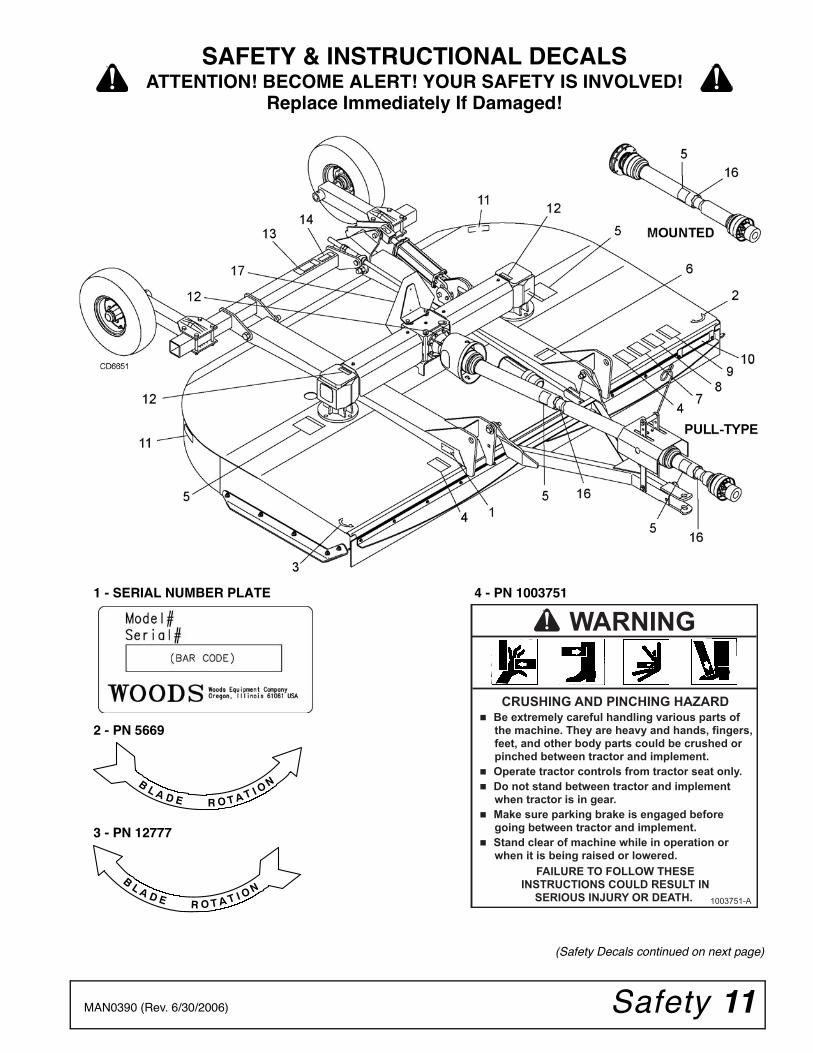
1 - SERIAL NUMBER PLATE
2 - PN 5669
3 - PN 12777
4 - PN 1003751
CRUSHING AND PINCHING HAZARD� Be extremely careful handling various parts of
the machine. They are heavy and hands, fingers, feet, and other body parts could be crushed or pinched between tractor and implement.
� Operate tractor controls from tractor seat only.
� Do not stand between tractor and implement when tractor is in gear.
� Make sure parking brake is engaged before going between tractor and implement.
� Stand clear of machine while in operation or when it is being raised or lowered.
FAILURE TO FOLLOW THESE INSTRUCTIONS COULD RESULT IN
SERIOUS INJURY OR DEATH.
WARNING
1003751-A
SAFETY & INSTRUCTIONAL DECALSATTENTION! BECOME ALERT! YOUR SAFETY IS INVOLVED!
Replace Immediately If Damaged!
(Safety Decals continued on next page)
12 Safety MAN0390 (Rev. 6/30/2006)
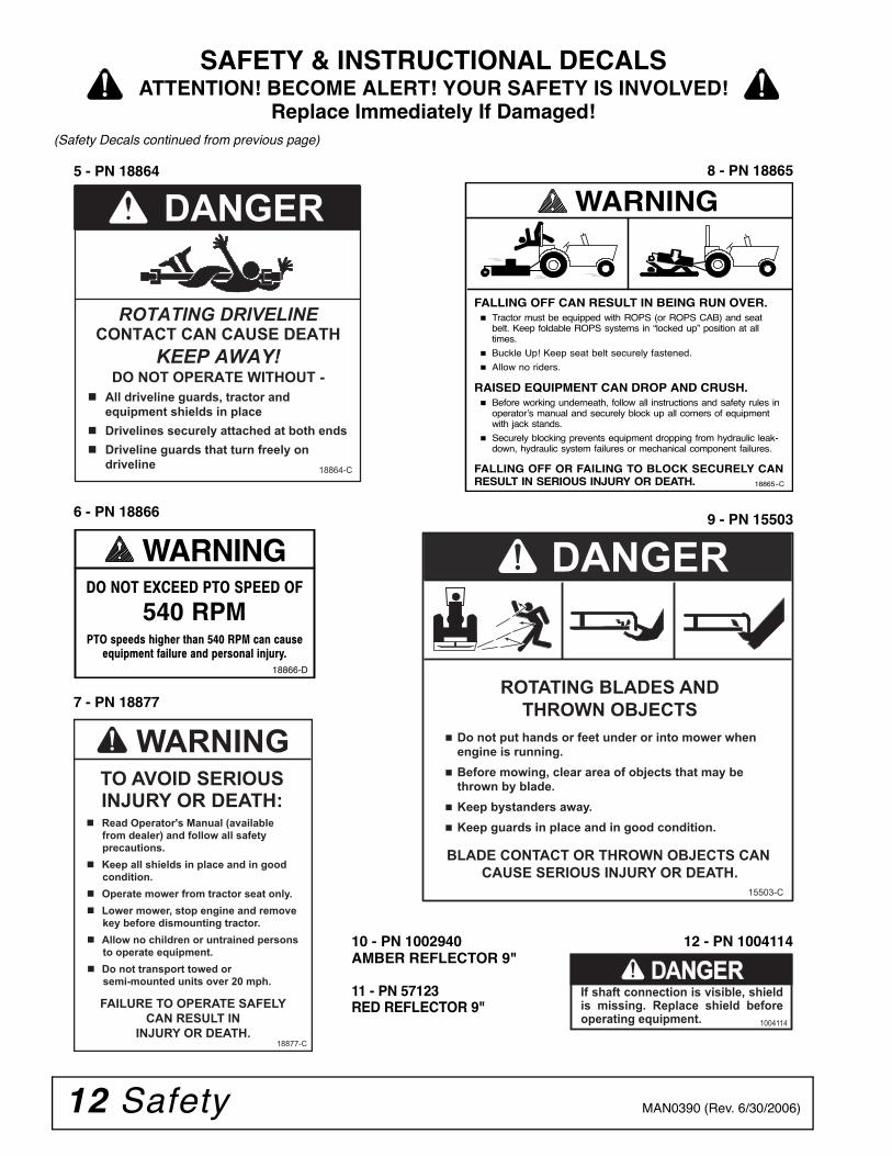
9 - PN 15503
FALLING OFF CAN RESULT IN BEING RUN OVER. Tractor must be equipped with ROPS (or ROPS CAB) and seat
belt. Keep foldable ROPS systems in “�locked up”�position at alltimes.
Buckle Up! Keep seat belt securely fastened.
Allow no riders.
RAISED EQUIPMENT CAN DROP AND CRUSH. Before working underneath, follow all instructions and safety rules in
operator’�s manual and securely block up all corners of equipmentwith jack stands.
Securely blocking prevents equipment dropping from hydraulic leak-down, hydraulic system failures or mechanical component failures.
FALLING OFF OR FAILING TO BLOCK SECURELY CANRESULT IN SERIOUS INJURY OR DEATH.
WARNING
18865--C
8 - PN 18865
�� ��� ������ ��� ���� �
540 RPM��� �� �� ���� � ���� ��� ��� ��� ����
����� �� ��� �� ��� � ��!�� ��"��#$
WARNING
18866-D
6 - PN 18866
ROTATING BLADES AND
THROWN OBJECTS
� Do not put hands or feet under or into mower when engine is running.
� Before mowing, clear area of objects that may be thrown by blade.
� Keep bystanders away.
� Keep guards in place and in good condition.
BLADE CONTACT OR THROWN OBJECTS CAN
CAUSE SERIOUS INJURY OR DEATH.
DANGER
15503-C
5 - PN 18864
DANGER
ROTATING DRIVELINE
CONTACT CAN CAUSE DEATH
KEEP AWAY!
DO NOT OPERATE WITHOUT -
� All driveline guards, tractor and
equipment shields in place
� Drivelines securely attached at both ends
� Driveline guards that turn freely on
driveline18864-C
10 - PN 1002940AMBER REFLECTOR 9"
11 - PN 57123RED REFLECTOR 9"
7 - PN 18877
WARNINGTO AVOID SERIOUS INJURY OR DEATH:
� Read Operator's Manual (available
from dealer) and follow all safety
precautions.
� Keep all shields in place and in good
condition.
� Operate mower from tractor seat only.
� Lower mower, stop engine and remove
key before dismounting tractor.
� Allow no children or untrained persons
to operate equipment.
� Do not transport towed or
semi-mounted units over 20 mph.
FAILURE TO OPERATE SAFELY
CAN RESULT IN
INJURY OR DEATH.18877-C
12 - PN 1004114
If shaft connection is visible, shield is missing. Replace shield before operating equipment.
DANGNGERER
1004114
SAFETY & INSTRUCTIONAL DECALSATTENTION! BECOME ALERT! YOUR SAFETY IS INVOLVED!
Replace Immediately If Damaged!(Safety Decals continued from previous page)
Safety 13MAN0390 (Rev. 6/30/2006)
SAFETY & INSTRUCTIONAL DECALSATTENTION! BECOME ALERT! YOUR SAFETY IS INVOLVED!
Replace Immediately If Damaged!
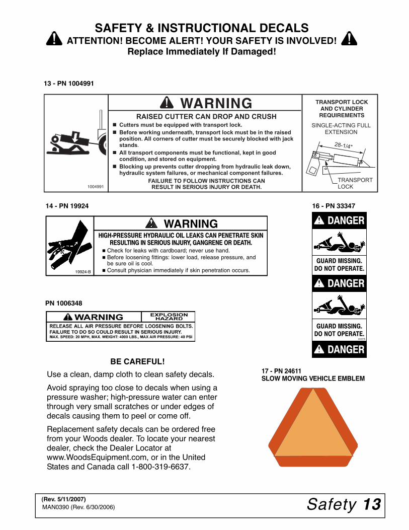
������������ ���� �� �� ���� ��� ��������� ������� ���� �� ������ ����� �������� �� ������
� Check for leaks with cardboard; never use hand.� Before loosening fittings: lower load, release pressure, and
be sure oil is cool.� Consult physician immediately if skin penetration occurs.
WARNING
19924-B
14 - PN 19924
13 - PN 1004991
TRANSPORT LOCK AND CYLINDER REQUIREMENTS
1004991TRANSPORT
LOCK
WARNINGRAISED CUTTER CAN DROP AND CRUSH
ers must be equipped with transport lock.Cutte
ds.stan
� ransport components must be functional, kept in goodAll tr
�� Blocking up prevents cutter dropping from hydraulic leak down,Blochydraulic system failures, or mechanical component failures.
FAILURE TO FOLLOW INSTRUCTIONS CAN RESULT IN SERIOUS INJURY OR DEATH.
28-1/4"
SINGLE-ACTING FULL
EXTENSION
BE CAREFUL!
Use a clean, damp cloth to clean safety decals.
Avoid spraying too close to decals when using a pressure washer; high-pressure water can enter through very small scratches or under edges of decals causing them to peel or come off.
Replacement safety decals can be ordered free from your Woods dealer. To locate your nearest dealer, check the Dealer Locator at www.WoodsEquipment.com, or in the United States and Canada call 1-800-319-6637.
����� ������
�� �� � �����
�����
33347E
�����
�����
����� ������
�� �� � �����
16 - PN 33347
17 - PN 24611SLOW MOVING VEHICLE EMBLEM
PN 1006348
(Rev. 5/11/2007)
14 Operation MAN0390 (Rev. 6/30/2006)
OPERATION
The operator is responsible for the safe operation ofthe cutter. The operator must be properly trained.Operators should be familiar with the cutter, the tractor,and all safety practices before starting operation. Readthe safety rules and safety decals on page 7 to page13.
This medium-duty cutter is designed for grass andweed mowing and shredding.
Recommended mowing speed for most conditions isfrom 2 to 5 mph.
Full chain or rubber shielding must be installedwhen operating in populated areas or other areaswhere thrown objects could injure people or dam-age property.
• If this machine is not equipped with full chainor rubber shielding, operation must be stoppedwhen anyone comes within 300 feet (92 m).• This shielding is designed to reduce the riskof thrown objects. The mower deck and protec-tive devices cannot prevent all objects fromescaping the blade enclosure in every mowingcondition. It is possible for objects to ricochetand escape, traveling as much as 300 feet (92 m).
Never allow riders on power unit or attachment.
Make sure spring-activated locking pin or collarslides freely and is seated firmly in tractor PTOspline groove.
Operate tractor PTO at 540 RPM. Do not exceed.
Do not allow bystanders in the area when oper-ating, attaching, removing, assembling, or servic-ing equipment.
Stop power unit and equipment immediatelyupon striking an obstruction. Turn off engine,remove key, inspect, and repair any damage beforeresuming operation.
Always wear relatively tight and belted clothingto avoid getting caught in moving parts. Wearsturdy, rough-soled work shoes and protectiveequipment for eyes, hair, hands, hearing, and head;and respirator or filter mask where appropriate.
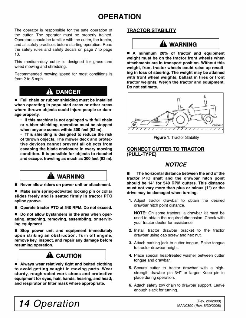
TRACTOR STABILITY
A minimum 20% of tractor and equipmentweight must be on the tractor front wheels whenattachments are in transport position. Without thisweight, front tractor wheels could raise up result-ing in loss of steering. The weight may be attainedwith front wheel weights, ballast in tires or fronttractor weights. Weigh the tractor and equipment.Do not estimate.
Figure 1. Tractor Stability
CONNECT CUTTER TO TRACTOR(PULL-TYPE)
NOTICE■ The horizontal distance between the end of thetractor PTO shaft and the drawbar hitch pointshould be 14" for 540 RPM cutters. This distancemust not vary more than plus or minus (1") or thedrive may be damaged when turning.
1. Adjust tractor drawbar to obtain the desireddrawbar hitch point distance.
NOTE: On some tractors, a drawbar kit must beused to obtain the required dimension. Check withyour tractor dealer for assistance.
2. Install tractor drawbar bracket to the tractordrawbar using cap screw and hex nut.
3. Attach parking jack to cutter tongue. Raise tongueto tractor drawbar height.
4. Place special heat-treated washer between cuttertongue and drawbar.
5. Secure cutter to tractor drawbar with a high-strength drawbar pin 3/4" or larger. Keep pin inplace during operation.
6. Attach safety tow chain to drawbar support. Leaveenough slack for turning.
������
�������
CAUTION
�������
(Rev. 2/6/2009)
Operation 15MAN0390 (Rev. 6/30/2006)
7. Connect cutter driveline to tractor PTO shaft,making sure the spring-activated lock pin slidesfreely and is seated in tractor PTO splined groove.
8. Remove parking jack from the tongue and attach itto the storage post on the front of the cutter.
9. Adjust H-frame bearing height so that the frontdriveline is parallel to the ground. Secure with 5/8 x5-21/32 clevis pin and 3/16 x 1-1/2 cotter pin.
10. Attach drive shaft shield to bearing housing usingtwo 3/8 x 1 cap screws and 3/8 lock washers.
Hydraulic Connection
1. Inspect hydraulic hoses to ensure they are in goodcondition.
2. Clean the fittings before connecting them to thetractor hydraulic ports.
3. Attach the hydraulic hose to the tractor.
4. Route the hose through the hose holder at thehitch and be sure the hose can slide freely in theholder. Do not allow hose slack to drag on theground or become caught on tractor protrusions.
5. From the operator position, start tractor and raiseand lower deck several times to purge trapped airfrom the hydraulic cylinder.
Interference Check
1. Be sure that tractor 3-point lift links do not interferewith hydraulic hoses, cutter driveline, or cutterframe.
2. Check for straight-ahead operation and at full-turning angles. If there is any interference, removethe lower lift links.
3. Contact between tractor lift links and cutter partscan cause damage, especially when turning.
CONNECT CUTTER TO TRACTOR(MOUNTED)
A minimum 20% of tractor and equipmentweight must be on the tractor front wheels whenattachments are in transport position. Without thisweight, front tractor wheels could raise up result-ing in loss of steering. The weight may be attainedwith front wheel weights, ballast in tires or fronttractor weights. Weigh the tractor and equipment.Do not estimate.
Tractor Adjustments
Before attaching tractor to cutter, install sway blocks orsway chains, or adjust stabilizer bars. Refer to the trac-tor operator's manual for instructions.
Install tractor front end weights as recommended bythe tractor manufacturer to provide 20% of weight onfront wheels.
DS96 Category 2 Standard Hitch
1. Position the tractor 3-point lower lift arms over thehitch pins and secure with 7/16 klik pins.
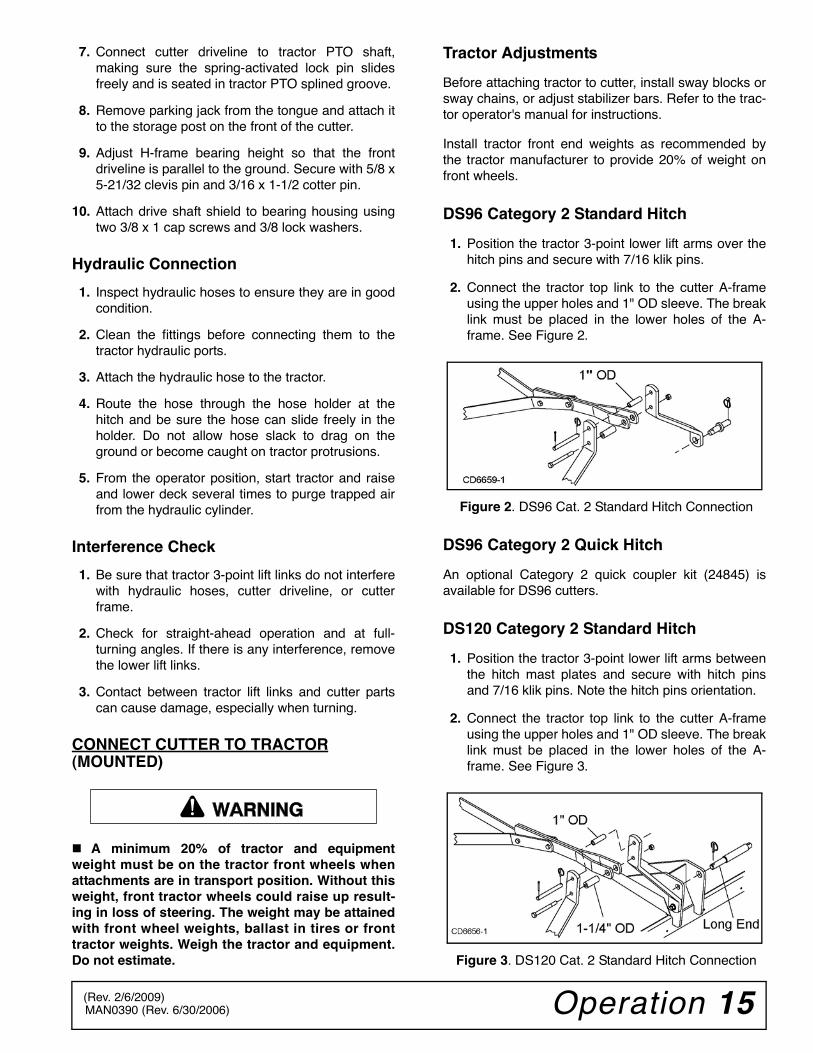
2. Connect the tractor top link to the cutter A-frameusing the upper holes and 1" OD sleeve. The breaklink must be placed in the lower holes of the A-frame. See Figure 2.
Figure 2. DS96 Cat. 2 Standard Hitch Connection
DS96 Category 2 Quick Hitch
An optional Category 2 quick coupler kit (24845) isavailable for DS96 cutters.
DS120 Category 2 Standard Hitch
1. Position the tractor 3-point lower lift arms betweenthe hitch mast plates and secure with hitch pinsand 7/16 klik pins. Note the hitch pins orientation.
2. Connect the tractor top link to the cutter A-frameusing the upper holes and 1" OD sleeve. The breaklink must be placed in the lower holes of the A-frame. See Figure 3.
Figure 3. DS120 Cat. 2 Standard Hitch Connection
�������
(Rev. 2/6/2009)
16 Operation MAN0390 (Rev. 6/30/2006)
DS120 Category 2 Quick Hitch
1. Position the hitch pins as shown in Figure 4.
2. Attach tractor with quick hitch to cutter and secureaccording to quick hitch manufacturer’sinstructions.
Figure 4. DS120 Category 2 Quick Hitch Connection
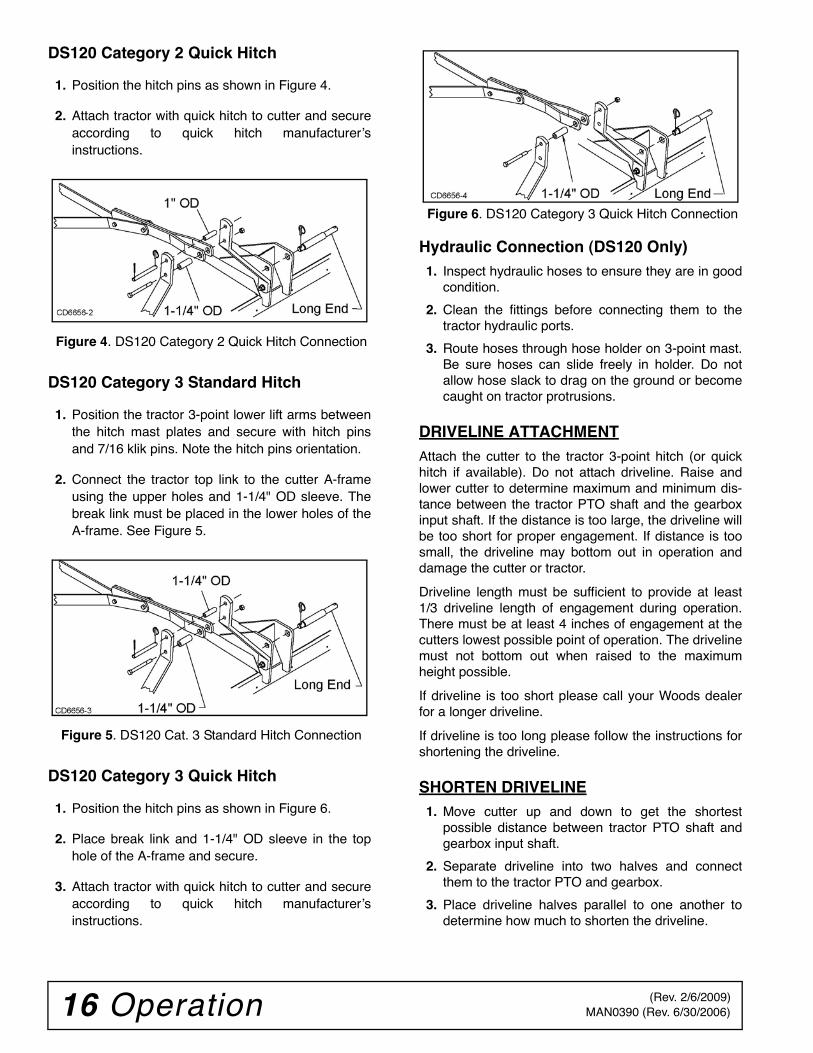
DS120 Category 3 Standard Hitch
1. Position the tractor 3-point lower lift arms betweenthe hitch mast plates and secure with hitch pinsand 7/16 klik pins. Note the hitch pins orientation.
2. Connect the tractor top link to the cutter A-frameusing the upper holes and 1-1/4" OD sleeve. Thebreak link must be placed in the lower holes of theA-frame. See Figure 5.
Figure 5. DS120 Cat. 3 Standard Hitch Connection
DS120 Category 3 Quick Hitch
1. Position the hitch pins as shown in Figure 6.
2. Place break link and 1-1/4" OD sleeve in the tophole of the A-frame and secure.
3. Attach tractor with quick hitch to cutter and secureaccording to quick hitch manufacturer’sinstructions.
Figure 6. DS120 Category 3 Quick Hitch Connection
Hydraulic Connection (DS120 Only)1. Inspect hydraulic hoses to ensure they are in good
condition.
2. Clean the fittings before connecting them to thetractor hydraulic ports.
3. Route hoses through hose holder on 3-point mast.Be sure hoses can slide freely in holder. Do notallow hose slack to drag on the ground or becomecaught on tractor protrusions.
DRIVELINE ATTACHMENTAttach the cutter to the tractor 3-point hitch (or quickhitch if available). Do not attach driveline. Raise andlower cutter to determine maximum and minimum dis-tance between the tractor PTO shaft and the gearboxinput shaft. If the distance is too large, the driveline willbe too short for proper engagement. If distance is toosmall, the driveline may bottom out in operation anddamage the cutter or tractor.
Driveline length must be sufficient to provide at least1/3 driveline length of engagement during operation.There must be at least 4 inches of engagement at thecutters lowest possible point of operation. The drivelinemust not bottom out when raised to the maximumheight possible.
If driveline is too short please call your Woods dealerfor a longer driveline.
If driveline is too long please follow the instructions forshortening the driveline.
SHORTEN DRIVELINE1. Move cutter up and down to get the shortest
possible distance between tractor PTO shaft andgearbox input shaft.
2. Separate driveline into two halves and connectthem to the tractor PTO and gearbox.
3. Place driveline halves parallel to one another todetermine how much to shorten the driveline.
(Rev. 2/6/2009)
Operation 17MAN0390 (Rev. 6/30/2006)
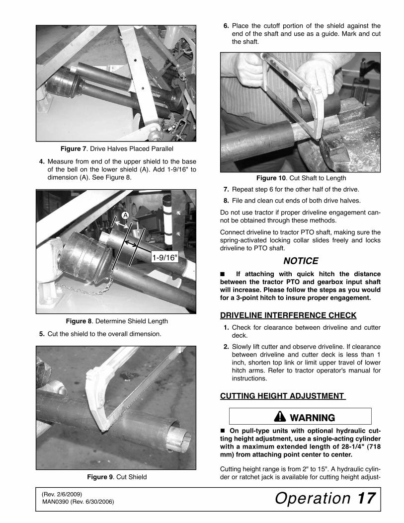
Figure 7. Drive Halves Placed Parallel
4. Measure from end of the upper shield to the baseof the bell on the lower shield (A). Add 1-9/16" todimension (A). See Figure 8.
Figure 8. Determine Shield Length
5. Cut the shield to the overall dimension.
Figure 9. Cut Shield
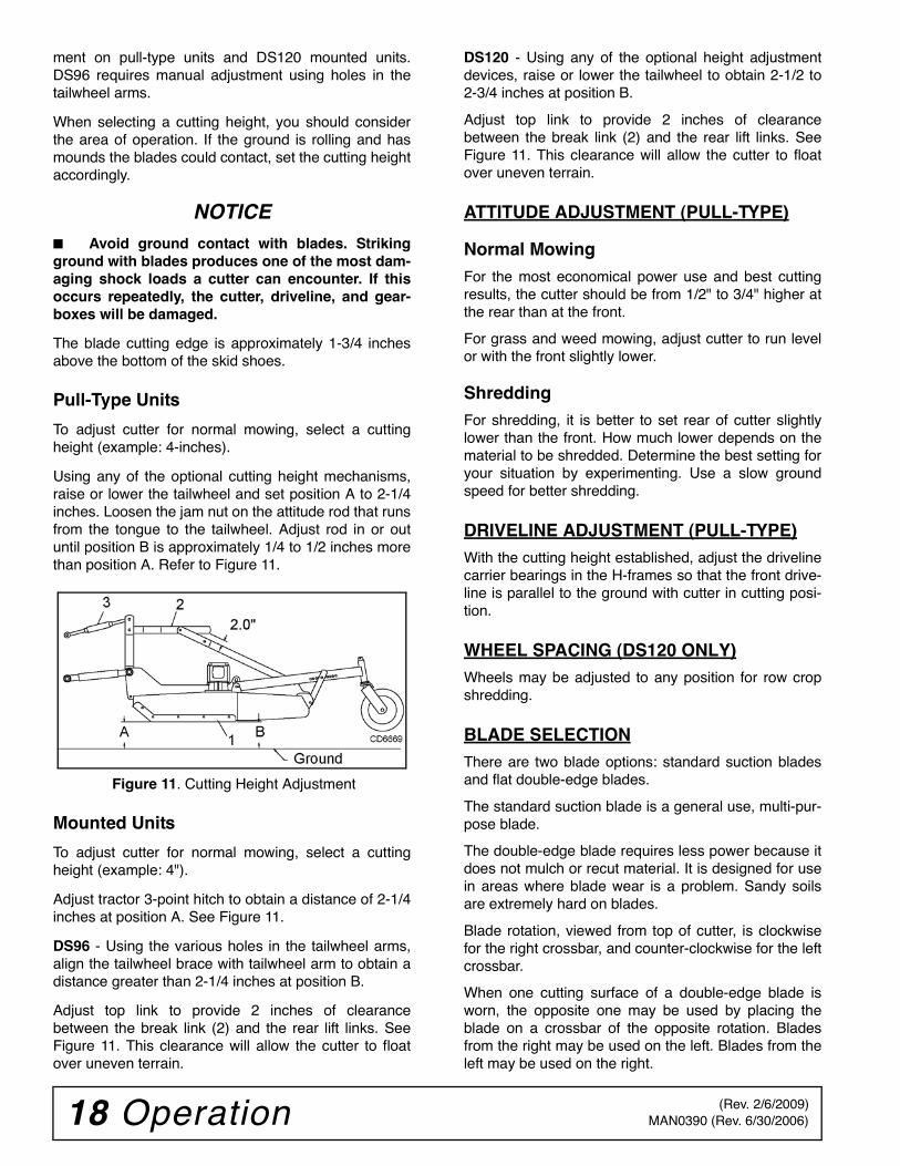
6. Place the cutoff portion of the shield against theend of the shaft and use as a guide. Mark and cutthe shaft.
Figure 10. Cut Shaft to Length
7. Repeat step 6 for the other half of the drive.
8. File and clean cut ends of both drive halves.
Do not use tractor if proper driveline engagement can-not be obtained through these methods.
Connect driveline to tractor PTO shaft, making sure thespring-activated locking collar slides freely and locksdriveline to PTO shaft.
NOTICE■ If attaching with quick hitch the distancebetween the tractor PTO and gearbox input shaftwill increase. Please follow the steps as you wouldfor a 3-point hitch to insure proper engagement.
DRIVELINE INTERFERENCE CHECK1. Check for clearance between driveline and cutter
deck.
2. Slowly lift cutter and observe driveline. If clearancebetween driveline and cutter deck is less than 1inch, shorten top link or limit upper travel of lowerhitch arms. Refer to tractor operator's manual forinstructions.
CUTTING HEIGHT ADJUSTMENT
On pull-type units with optional hydraulic cut-ting height adjustment, use a single-acting cylinderwith a maximum extended length of 28-1/4" (718mm) from attaching point center to center.
Cutting height range is from 2" to 15". A hydraulic cylin-der or ratchet jack is available for cutting height adjust-
1-9/16"
A
�������
(Rev. 2/6/2009)
18 Operation MAN0390 (Rev. 6/30/2006)
ment on pull-type units and DS120 mounted units.DS96 requires manual adjustment using holes in thetailwheel arms.
When selecting a cutting height, you should considerthe area of operation. If the ground is rolling and hasmounds the blades could contact, set the cutting heightaccordingly.
NOTICE■ Avoid ground contact with blades. Strikingground with blades produces one of the most dam-aging shock loads a cutter can encounter. If thisoccurs repeatedly, the cutter, driveline, and gear-boxes will be damaged.
The blade cutting edge is approximately 1-3/4 inchesabove the bottom of the skid shoes.
Pull-Type Units
To adjust cutter for normal mowing, select a cuttingheight (example: 4-inches).
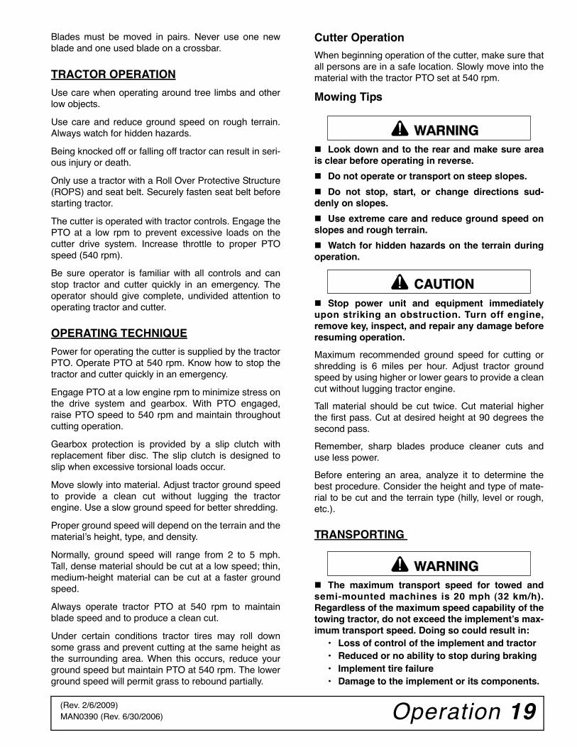
Using any of the optional cutting height mechanisms,raise or lower the tailwheel and set position A to 2-1/4inches. Loosen the jam nut on the attitude rod that runsfrom the tongue to the tailwheel. Adjust rod in or outuntil position B is approximately 1/4 to 1/2 inches morethan position A. Refer to Figure 11.
Figure 11. Cutting Height Adjustment
Mounted Units
To adjust cutter for normal mowing, select a cuttingheight (example: 4").
Adjust tractor 3-point hitch to obtain a distance of 2-1/4inches at position A. See Figure 11.
DS96 - Using the various holes in the tailwheel arms,align the tailwheel brace with tailwheel arm to obtain adistance greater than 2-1/4 inches at position B.
Adjust top link to provide 2 inches of clearancebetween the break link (2) and the rear lift links. SeeFigure 11. This clearance will allow the cutter to floatover uneven terrain.
DS120 - Using any of the optional height adjustmentdevices, raise or lower the tailwheel to obtain 2-1/2 to2-3/4 inches at position B.
Adjust top link to provide 2 inches of clearancebetween the break link (2) and the rear lift links. SeeFigure 11. This clearance will allow the cutter to floatover uneven terrain.
ATTITUDE ADJUSTMENT (PULL-TYPE)
Normal Mowing
For the most economical power use and best cuttingresults, the cutter should be from 1/2" to 3/4" higher atthe rear than at the front.
For grass and weed mowing, adjust cutter to run levelor with the front slightly lower.
ShreddingFor shredding, it is better to set rear of cutter slightlylower than the front. How much lower depends on thematerial to be shredded. Determine the best setting foryour situation by experimenting. Use a slow groundspeed for better shredding.
DRIVELINE ADJUSTMENT (PULL-TYPE)With the cutting height established, adjust the drivelinecarrier bearings in the H-frames so that the front drive-line is parallel to the ground with cutter in cutting posi-tion.
WHEEL SPACING (DS120 ONLY)Wheels may be adjusted to any position for row cropshredding.
BLADE SELECTIONThere are two blade options: standard suction bladesand flat double-edge blades.
The standard suction blade is a general use, multi-pur-pose blade.
The double-edge blade requires less power because itdoes not mulch or recut material. It is designed for usein areas where blade wear is a problem. Sandy soilsare extremely hard on blades.
Blade rotation, viewed from top of cutter, is clockwisefor the right crossbar, and counter-clockwise for the leftcrossbar.
When one cutting surface of a double-edge blade isworn, the opposite one may be used by placing theblade on a crossbar of the opposite rotation. Bladesfrom the right may be used on the left. Blades from theleft may be used on the right.
(Rev. 2/6/2009)
Operation 19MAN0390 (Rev. 6/30/2006)
Blades must be moved in pairs. Never use one newblade and one used blade on a crossbar.
TRACTOR OPERATION
Use care when operating around tree limbs and otherlow objects.
Use care and reduce ground speed on rough terrain.Always watch for hidden hazards.
Being knocked off or falling off tractor can result in seri-ous injury or death.
Only use a tractor with a Roll Over Protective Structure(ROPS) and seat belt. Securely fasten seat belt beforestarting tractor.
The cutter is operated with tractor controls. Engage thePTO at a low rpm to prevent excessive loads on thecutter drive system. Increase throttle to proper PTOspeed (540 rpm).
Be sure operator is familiar with all controls and canstop tractor and cutter quickly in an emergency. Theoperator should give complete, undivided attention tooperating tractor and cutter.
OPERATING TECHNIQUE
Power for operating the cutter is supplied by the tractorPTO. Operate PTO at 540 rpm. Know how to stop thetractor and cutter quickly in an emergency.
Engage PTO at a low engine rpm to minimize stress onthe drive system and gearbox. With PTO engaged,raise PTO speed to 540 rpm and maintain throughoutcutting operation.
Gearbox protection is provided by a slip clutch withreplacement fiber disc. The slip clutch is designed toslip when excessive torsional loads occur.
Move slowly into material. Adjust tractor ground speedto provide a clean cut without lugging the tractorengine. Use a slow ground speed for better shredding.
Proper ground speed will depend on the terrain and thematerial’s height, type, and density.
Normally, ground speed will range from 2 to 5 mph.Tall, dense material should be cut at a low speed; thin,medium-height material can be cut at a faster groundspeed.
Always operate tractor PTO at 540 rpm to maintainblade speed and to produce a clean cut.
Under certain conditions tractor tires may roll downsome grass and prevent cutting at the same height asthe surrounding area. When this occurs, reduce yourground speed but maintain PTO at 540 rpm. The lowerground speed will permit grass to rebound partially.
Cutter Operation
When beginning operation of the cutter, make sure thatall persons are in a safe location. Slowly move into thematerial with the tractor PTO set at 540 rpm.
Mowing Tips
Look down and to the rear and make sure areais clear before operating in reverse.
Do not operate or transport on steep slopes.
Do not stop, start, or change directions sud-denly on slopes.
Use extreme care and reduce ground speed onslopes and rough terrain.
Watch for hidden hazards on the terrain duringoperation.
Stop power unit and equipment immediatelyupon striking an obstruction. Turn off engine,remove key, inspect, and repair any damage beforeresuming operation.
Maximum recommended ground speed for cutting orshredding is 6 miles per hour. Adjust tractor groundspeed by using higher or lower gears to provide a cleancut without lugging tractor engine.
Tall material should be cut twice. Cut material higherthe first pass. Cut at desired height at 90 degrees thesecond pass.
Remember, sharp blades produce cleaner cuts anduse less power.
Before entering an area, analyze it to determine thebest procedure. Consider the height and type of mate-rial to be cut and the terrain type (hilly, level or rough,etc.).
TRANSPORTING
The maximum transport speed for towed andsemi-mounted machines is 20 mph (32 km/h).Regardless of the maximum speed capability of thetowing tractor, do not exceed the implement’s max-imum transport speed. Doing so could result in:
• Loss of control of the implement and tractor• Reduced or no ability to stop during braking• Implement tire failure• Damage to the implement or its components.
�������
CAUTION
�������
(Rev. 2/6/2009)
20 Operation MAN0390 (Rev. 6/30/2006)
Use additional caution and reduce speed whenunder adverse surface conditions, turning, or oninclines.
Never tow this implement with a motor vehicle.
1. Always transport with cutter in raised, lockedposition.
2. Raise cutter with hydraulic cylinder.
3. Rotate transport lock over cylinder rod. See Figure33 on page 38.
4. Lower cylinder against transport lock.
5. To lower cutter for operation, extend hydrauliccylinder. Rotate transport lock back away fromcylinder rod. Lower to desired cutting height.
STORAGE
Keep children and bystanders away from stor-age area.
On Mounted and Semi-Mounted Cutters:
Disconnect cutter driveshaft and secure up offground. Raise cutter with 3-point hitch. Placeblocks under cutter side skids. Lower cutter ontoblocks. Disconnect hydraulic lines to optional cyl-inder. Disconnect cutter from tractor 3-point hitchand carefully drive tractor away from cutter.
On Pull-Type Cutters:
Raise cutter and block securely. Block wheelsand raise tongue with jack. Disconnect hydrauliclines to optional cylinder. Disconnect driveline andsecure up off the ground.
PRE-OPERATION CHECK LIST(OWNER'S RESPONSIBILITY)
___ Review and follow all safety rules and safetydecal instructions on page 7 to page 13.
___ Check that all safety decals are installed and ingood condition. Replace if damaged.
___ Check that equipment is properly and securelyattached to tractor.
___ Make sure driveline spring-activated locking pinor collar slides freely and is seated firmly in trac-tor PTO spline groove.
___ Set tractor PTO at correct rpm for your equip-ment.
___ Lubricate all grease fitting locations. Make surePTO shaft slip joint is lubricated.
___ Check that all hydraulic hoses and fittings are ingood condition and not leaking before startingtractor. Check that hoses are not twisted, bentsharply, kinked, frayed, or pulled tight. Replaceany damaged hoses immediately.
___ Raise and lower equipment to make sure air ispurged from hydraulic cylinders and hoses.
___ Check that all hardware is properly installed andsecured.
___ Check to ensure blades are sharp, in good condi-tion, and installed correctly. Replace if damaged.
___ Make sure tractor ROPS or ROPS cab and seatbelt are in good condition. Keep seat beltsecurely fastened during operation.
___ Check that shields and guards are properlyinstalled and in good condition. Replace if dam-aged.
___ Check cutting height, front-to-rear attitude, andtop link adjustment.
___ Before starting engine, operator must be in trac-tor seat with seat belt fastened. Place transmis-sion in neutral or park, engage brake anddisengage tractor PTO.
___ Inspect area to be cut and remove stones,branches, or other hard objects that might bethrown and cause injury or damage.
___ Check that chain shielding is in good conditionand replace any damaged chain links.
___ Make sure tractor 3-point lift links do not interferewith hydraulic hoses or driveline throughout fullturning range.
�������
�������
(Rev. 4/6/2007)
Owner Service 21MAN0390 (Rev. 4/6/2007)
OWNER SERVICE
The information in this section is written for operatorswho possess basic mechanical skills. If you need help,your dealer has trained service technicians available.For your protection, read and follow the safety informa-tion in this manual.
Keep all persons away from operator controlarea while performing adjustments, service, ormaintenance.
If you do not understand any part of this manualand need assistance, see your dealer.
Always wear relatively tight and belted clothingto avoid entanglement in moving parts. Wearsturdy, rough-soled work shoes and protectiveequipment for eyes, hair, hands, hearing, and head;and respirator or filter mask where appropriate.
BLOCKING METHOD
Never go underneath equipment (lowered to theground or raised) unless it is properly blocked andsecured. Never place any part of the body under-neath equipment or between moveable parts evenwhen the engine has been turned off. Hydraulicsystem leak down, hydraulic system failures,mechanical failures, or movement of control leverscan cause equipment to drop or rotate unexpect-edly and cause severe injury or death. Follow Oper-ator's Manual instructions for working underneathand blocking requirements or have work done by aqualified dealer.
To minimize the potential hazards of working under-neath the cutter, follow these procedures:
1. Jackstands with a load rating of 1000 lbs. or moreare the only approved blocking device for thiscutter. Install a minimum of four jackstands (shownby Xs in Figure 12) under the cutter before workingunderneath unit.
Do not position jackstands under wheels, axles, orwheel supports. Components can rotate and causecutter to fall.
2. Consider the overall stability of the blocked unit.Just placing jackstands underneath will not ensureyour safety.
The working surface must be level and solid tosupport the weight on the jackstands. Make surejackstands are stable, both top and bottom. Makesure cutter is approximately level.
3. With full cutter weight lowered onto jackstands, testblocking stability before working underneath.
4. If cutter is attached to tractor when blocking, setthe brakes, remove key, and block cutter beforeworking underneath.
5. Securely block rear tractor wheels, in front andbehind. Tighten tractor lower 3-point arm anti-swaymechanism to prevent side-to-side movement.
LUBRICATION
Do not let excess grease collect on or around parts,particularly when operating in sandy areas.
See Figure 12 for lubrication points and frequency orlubrication based on normal operating conditions.Severe or unusual conditions may require more fre-quent lubrication.
Use a lithium grease of #2 consistency with a MOLY(molybdenum disulfide) additive for all locations unlessotherwise noted. Be sure to clean fittings thoroughlybefore attaching grease gun. One good pump of mostguns is sufficient when the lubrication schedule is fol-lowed.
Gearbox Lubrication1. Use a high quality gear oil with a viscosity index of
80W or 90W and an API service rating of GL-4 or -5 in gearboxes.
2. Fill gearbox until oil runs out the the lower hole onback side of center gearbox or side hole on spindlegearboxs. Check gearboxs daily for evidence ofleakage, and contact your dealer if leakage occurs.
Driveline Lubrication1. Lubricate the driveline slip joint every eight
operating hours. Failure to maintain properlubrication could result in damage to U-joints,gearbox, and driveline.
2. Lower cutter to ground, disconnect driveline fromtractor PTO shaft, and slide halves apart but do notdisconnect from each other.
3. Apply a bead of grease completely around malehalf where it meets female half. Slide drive halvesover each other several times to distribute grease.
4. Grease side drive yoke where yoke attaches toside gearbox.
�������
CAUTION
�������
(Rev. 10/5/2007)
22 Owner Service MAN0390 (Rev. 4/6/2007)
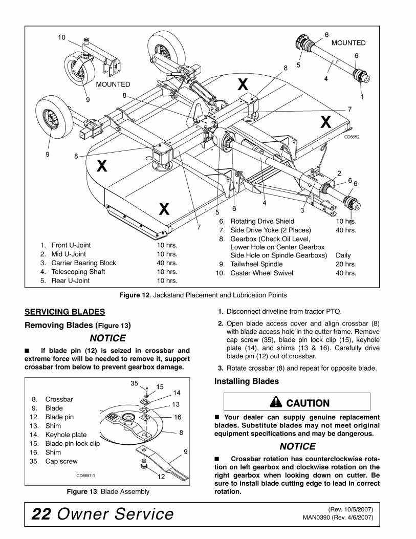
Figure 12. Jackstand Placement and Lubrication Points
SERVICING BLADES
Removing Blades (Figure 13)
NOTICE■ If blade pin (12) is seized in crossbar andextreme force will be needed to remove it, supportcrossbar from below to prevent gearbox damage.
Figure 13. Blade Assembly
1. Disconnect driveline from tractor PTO.
2. Open blade access cover and align crossbar (8)with blade access hole in the cutter frame. Removecap screw (35), blade pin lock clip (15), keyholeplate (14), and shims (13 & 16). Carefully driveblade pin (12) out of crossbar.
3. Rotate crossbar (8) and repeat for opposite blade.
Installing Blades
Your dealer can supply genuine replacementblades. Substitute blades may not meet originalequipment specifications and may be dangerous.
NOTICE■ Crossbar rotation has counterclockwise rota-tion on left gearbox and clockwise rotation on theright gearbox when looking down on cutter. Besure to install blade cutting edge to lead in correctrotation.
6. Rotating Drive Shield 10 hrs.7. Side Drive Yoke (2 Places) 40 hrs.8. Gearbox (Check Oil Level,
Lower Hole on Center GearboxSide Hole on Spindle Gearboxs) Daily
9. Tailwheel Spindle 20 hrs.10. Caster Wheel Swivel 40 hrs.
1. Front U-Joint 10 hrs.2. Mid U-Joint 10 hrs.3. Carrier Bearing Block 40 hrs.4. Telescoping Shaft 10 hrs.5. Rear U-Joint 10 hrs.
8. Crossbar9. Blade
12. Blade pin13. Shim14. Keyhole plate15. Blade pin lock clip16. Shim35. Cap screw
CAUTION
(Rev. 10/5/2007)
Owner Service 23MAN0390 (Rev. 4/6/2007)
NOTE: Always replace or sharpen both blades at thesame time.
1. Inspect blade pin (12) for nicks or gouges, and ifyou find any, replace the blade pin.
2. Insert blade pin through the blade (9). Bladeshould swivel on blade pin; if it doesn’t, determinethe cause and correct.
3. Align crossbar (8) with blade access hole in cutterframe. Apply a liberal coating of Never Seez orequivalent to blade pin and crossbar hole. Makesure blade offset is away from cutter. Push bladepin through crossbar. Pin should rotate freely priorto installing blade clip (15).
4. Install shims (13 & 16) over blade pin.NOTE: Only use enough shims to allow keyholeplate (14) to slide into blade pin groove.
5. Install blade clip (15) over keyhole plate and intoblade pin groove.
6. Secure into position with cap screw (35). Torquecap screw to 85 lbs-ft.
7. Repeat steps for opposite side.
NOTE: Blade should be snug but should swivel onpin without having to exert excessive force. Keepany spacers not used in the installation as replace-ments or for future installation.
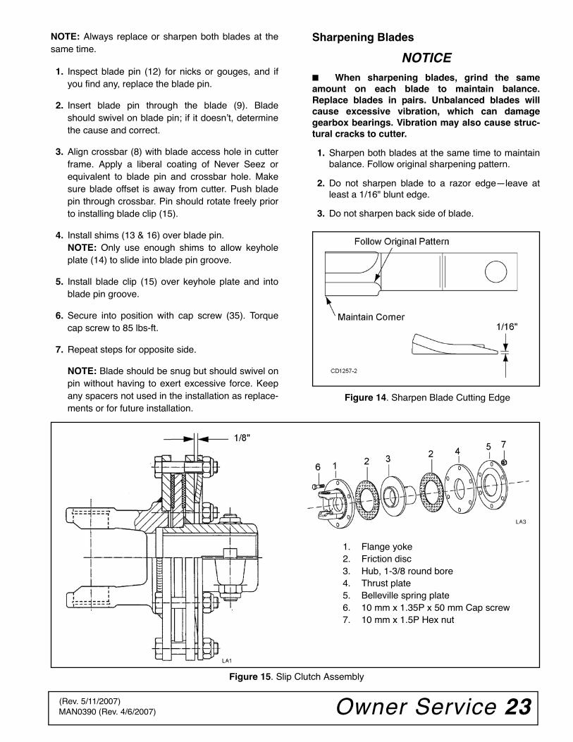
Sharpening Blades
NOTICE■ When sharpening blades, grind the sameamount on each blade to maintain balance.Replace blades in pairs. Unbalanced blades willcause excessive vibration, which can damagegearbox bearings. Vibration may also cause struc-tural cracks to cutter.
1. Sharpen both blades at the same time to maintainbalance. Follow original sharpening pattern.
2. Do not sharpen blade to a razor edge—leave atleast a 1/16" blunt edge.
3. Do not sharpen back side of blade.
Figure 14. Sharpen Blade Cutting Edge
Figure 15. Slip Clutch Assembly
1. Flange yoke2. Friction disc3. Hub, 1-3/8 round bore4. Thrust plate5. Belleville spring plate6. 10 mm x 1.35P x 50 mm Cap screw7. 10 mm x 1.5P Hex nut
(Rev. 5/11/2007)
24 Owner Service MAN0390 (Rev. 4/6/2007)
ADJUSTING SLIP CLUTCHThe slip clutch is designed to slip so that the gearboxand driveline are protected if the cutter strikes anobstruction. A new slip clutch or one that has been instorage over the winter may seize. Before operatingthe cutter, make sure it will slip by performing the fol-lowing operation:
1. Turn off tractor engine and remove key. Removedriveline from tractor PTO. Loosen six 10 mm capscrews (6) to remove all tension from Bellevillespring plate (5).
2. Hold clutch hub (3) solid and turn shaft to makesure clutch slips.
3. If clutch does not slip freely, disassemble and cleanthe thrust plate faces (4), flange yoke (1), andclutch hub (3).
4. Reassemble clutch. Tighten Belleville spring (5)until it is against the thrust plate (4) of the clutch,and then back off each of the six nuts by two fullrevolutions. The gap between Belleville spring andthrust plate should be 1/8" as shown in Figure 15.
5. If a clutch continues to slip when the spring iscompressed to 1/8", check friction discs (2) for
excessive wear. Discs are 1/8" when new. Replacediscs after 1/16" wear. Minimum disc thickness is1/16".
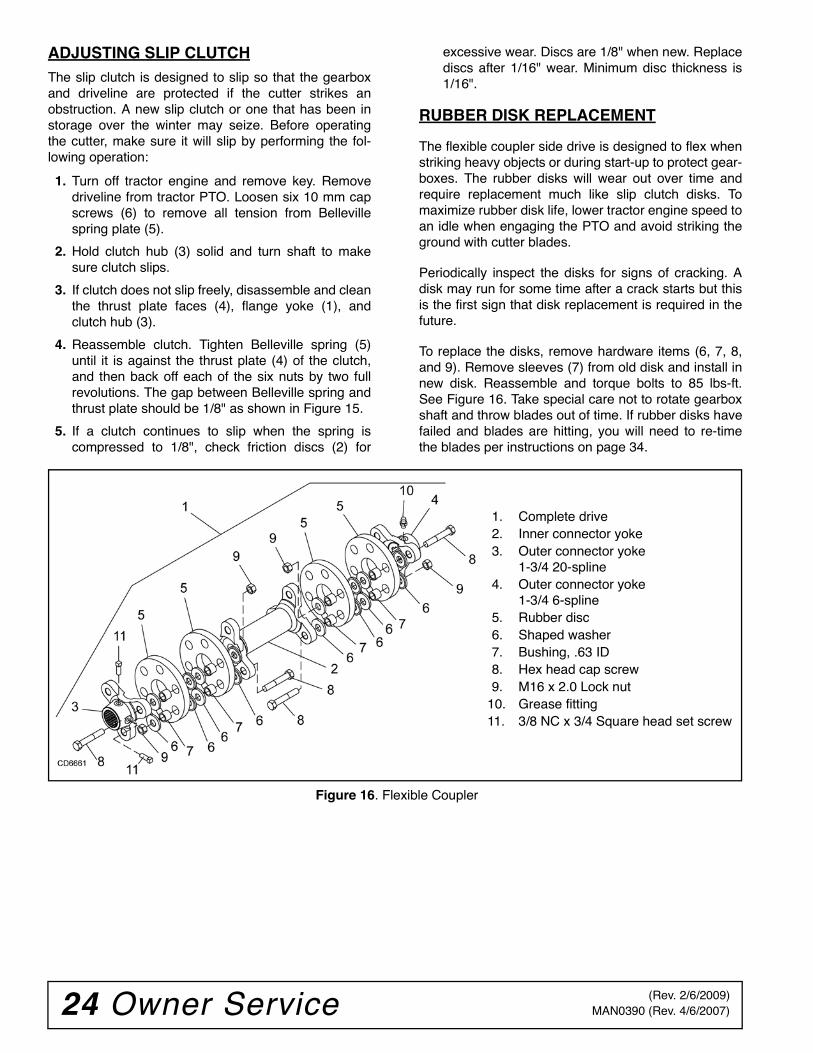
RUBBER DISK REPLACEMENT
The flexible coupler side drive is designed to flex whenstriking heavy objects or during start-up to protect gear-boxes. The rubber disks will wear out over time andrequire replacement much like slip clutch disks. Tomaximize rubber disk life, lower tractor engine speed toan idle when engaging the PTO and avoid striking theground with cutter blades.
Periodically inspect the disks for signs of cracking. Adisk may run for some time after a crack starts but thisis the first sign that disk replacement is required in thefuture.
To replace the disks, remove hardware items (6, 7, 8,and 9). Remove sleeves (7) from old disk and install innew disk. Reassemble and torque bolts to 85 lbs-ft.See Figure 16. Take special care not to rotate gearboxshaft and throw blades out of time. If rubber disks havefailed and blades are hitting, you will need to re-timethe blades per instructions on page 34.
Figure 16. Flexible Coupler
1. Complete drive2. Inner connector yoke3. Outer connector yoke
1-3/4 20-spline4. Outer connector yoke
1-3/4 6-spline5. Rubber disc6. Shaped washer7. Bushing, .63 ID8. Hex head cap screw9. M16 x 2.0 Lock nut
10. Grease fitting11. 3/8 NC x 3/4 Square head set screw
(Rev. 2/6/2009)
Owner Service 25MAN0390 (Rev. 4/6/2007)
SHIELDING REPAIR
Full chain or rubber shielding is required for allnon-agricultural mowing. Full shielding is also rec-ommended for all agricultural use to further reducethe risk of thrown objects.
Repairing Rubber Shielding
Inspect belting and rear bands each day of operationand replace if bent, cracked, or broken.
Repairing Optional Chain Shielding
Inspect chain shielding each day of operation andreplace any broken or missing chains as required.
CLEANING
After Each Use
● Remove large debris such as clumps of dirt, grass,crop residue, etc. from machine.
● Inspect machine and replace worn or damagedparts.
● Replace any safety decals that are missing or notreadable.
Periodically or Before Extended Storage
● Clean large debris such as clumps of dirt, grass,crop residue, etc. from machine.
● Remove the remainder using a low-pressure waterspray.
1. Be careful when spraying near scratched or tornsafety decals or near edges of decals as waterspray can peel decal off surface.
2. Be careful when spraying near chipped orscratched paint as water spray can lift paint.
3. If a pressure washer is used, follow the advice ofthe pressure washer manufacturer.
● Inspect machine and replace worn or damagedparts.
● Sand down scratches and the edges of areas ofmissing paint and coat with Woods spray paint ofmatching color (purchase from your Woodsdealer).
● Replace any safety decals that are missing or notreadable (supplied free by your Woods dealer).See Safety Decals section for location drawing.
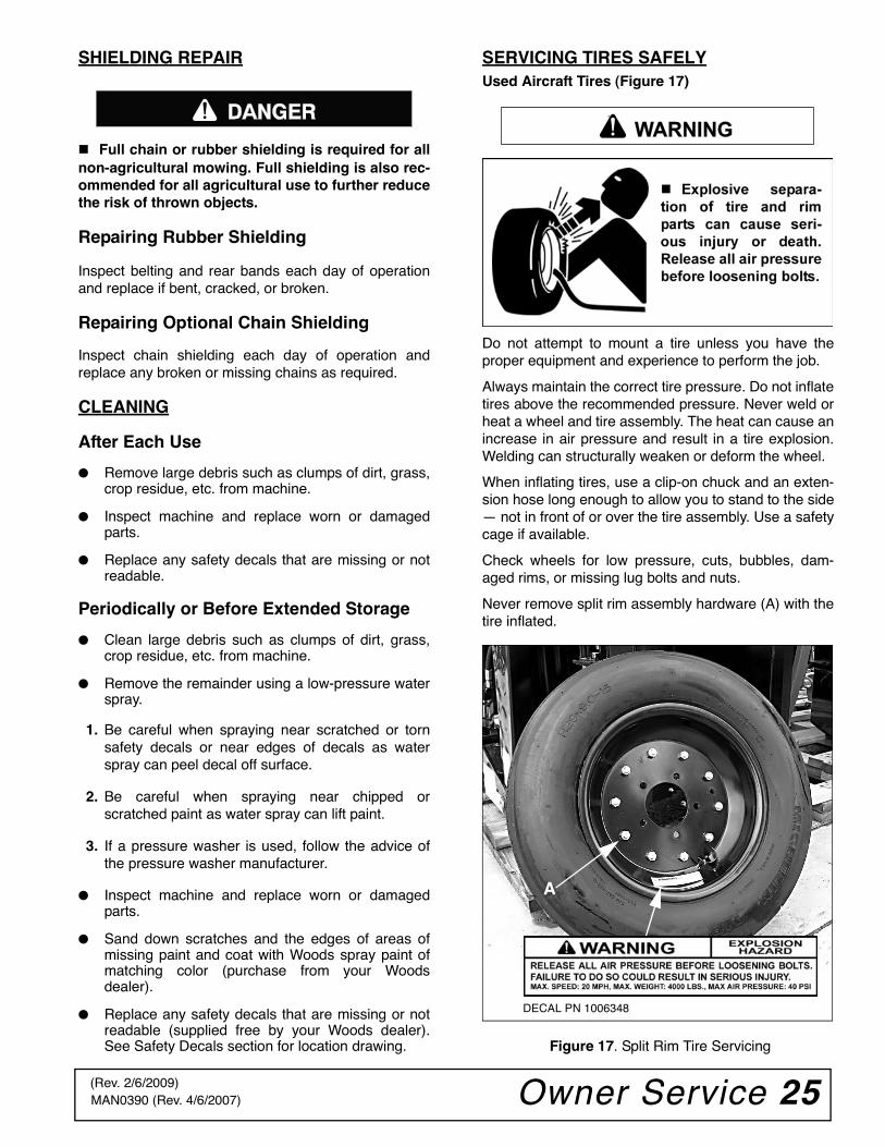
SERVICING TIRES SAFELYUsed Aircraft Tires (Figure 17)
Do not attempt to mount a tire unless you have theproper equipment and experience to perform the job.
Always maintain the correct tire pressure. Do not inflatetires above the recommended pressure. Never weld orheat a wheel and tire assembly. The heat can cause anincrease in air pressure and result in a tire explosion.Welding can structurally weaken or deform the wheel.
When inflating tires, use a clip-on chuck and an exten-sion hose long enough to allow you to stand to the side— not in front of or over the tire assembly. Use a safetycage if available.
Check wheels for low pressure, cuts, bubbles, dam-aged rims, or missing lug bolts and nuts.
Never remove split rim assembly hardware (A) with thetire inflated.
Figure 17. Split Rim Tire Servicing
������WARNING
A
DECAL PN 1006348
(Rev. 2/6/2009)
26 Troubleshooting MAN0390 (Rev. 4/6/2007)
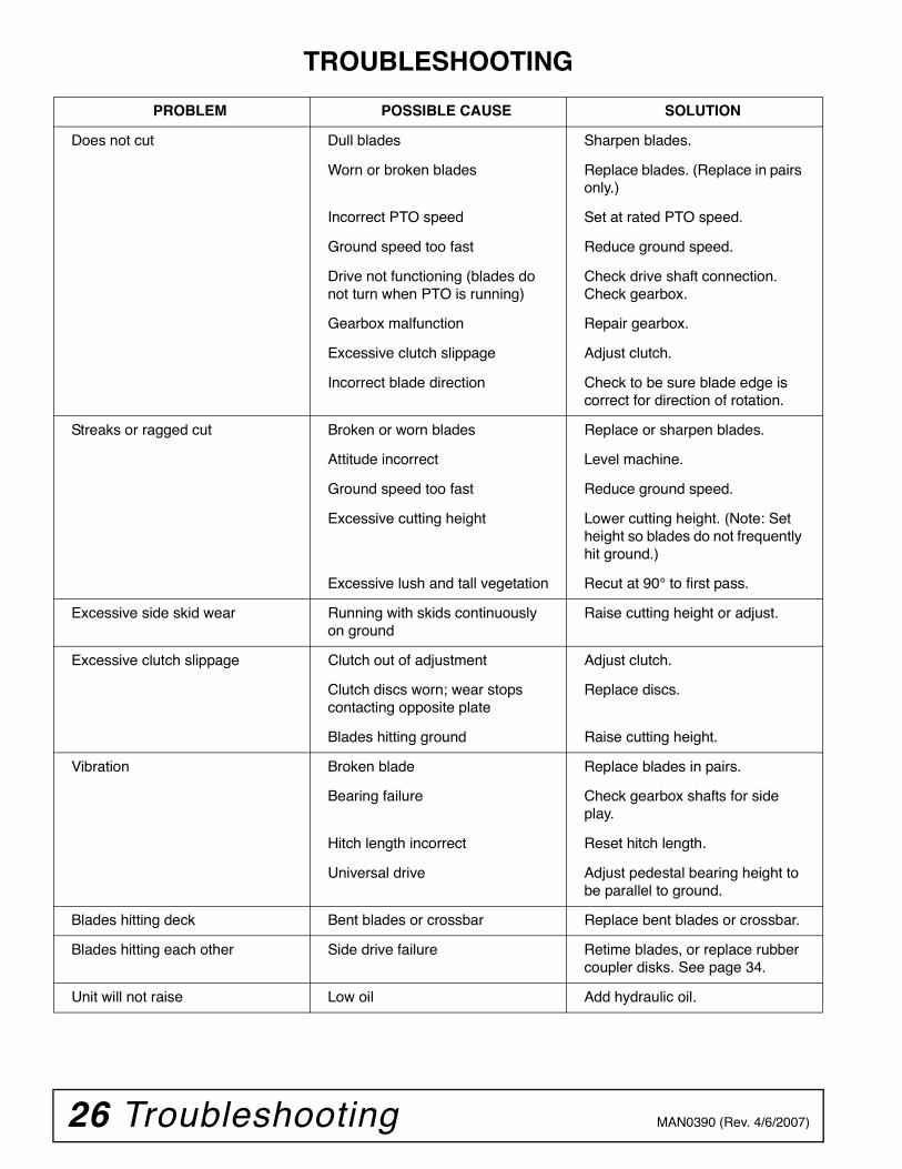
TROUBLESHOOTING
PROBLEM POSSIBLE CAUSE SOLUTION
Does not cut Dull blades Sharpen blades.
Worn or broken blades Replace blades. (Replace in pairs only.)
Incorrect PTO speed Set at rated PTO speed.
Ground speed too fast Reduce ground speed.
Drive not functioning (blades do not turn when PTO is running)
Check drive shaft connection.Check gearbox.
Gearbox malfunction Repair gearbox.
Excessive clutch slippage Adjust clutch.
Incorrect blade direction Check to be sure blade edge is correct for direction of rotation.
Streaks or ragged cut Broken or worn blades Replace or sharpen blades.
Attitude incorrect Level machine.
Ground speed too fast Reduce ground speed.
Excessive cutting height Lower cutting height. (Note: Set height so blades do not frequently hit ground.)
Excessive lush and tall vegetation Recut at 90° to first pass.
Excessive side skid wear Running with skids continuously on ground
Raise cutting height or adjust.
Excessive clutch slippage Clutch out of adjustment Adjust clutch.
Clutch discs worn; wear stops contacting opposite plate
Replace discs.
Blades hitting ground Raise cutting height.
Vibration Broken blade Replace blades in pairs.
Bearing failure Check gearbox shafts for side play.
Hitch length incorrect Reset hitch length.
Universal drive Adjust pedestal bearing height to be parallel to ground.
Blades hitting deck Bent blades or crossbar Replace bent blades or crossbar.
Blades hitting each other Side drive failure Retime blades, or replace rubber coupler disks. See page 34.
Unit will not raise Low oil Add hydraulic oil.
Dealer Service 27MAN0390 (Rev. 4/6/2007)
DEALER SERVICEThe information in this section is written for dealer ser-vice personnel. The repair described here requiresspecial skills and tools. If your shop is not properlyequipped or your mechanics are not properly trained inthis type of repair, you may be time and money aheadto replace complete assemblies.
Before working underneath, disconnect drive-line, raise cutter, lock in transport position, andblock cutter securely. Hydraulic system leak downand failure of mechanical or hydraulic system cancause equipment to drop. Keep all persons away from operator controlarea while performing adjustments, service, ormaintenance.
Always wear relatively tight and belted clothingto avoid getting caught in moving parts. Wearsturdy, rough-soled work shoes and protectiveequipment for eyes, hair, hands, hearing, and head;and respirator or filter mask where appropriate.
GEARBOX MAINTENANCE
NOTE: Read this entire section before starting anyrepair. Many steps are dependent on each other.
1. Fill gearbox with SAE 80W or 90W gear lube until itruns out the side level plug.
NOTE: Repair to this gearbox is limited to replac-ing bearings, seals, and gaskets. Replacing gears,shafts, and a housing is not cost effective. Pur-chasing a complete gearbox is more economical.
2. Inspect gearbox for leakage and bad bearings.Leakage is a very serious problem and must becorrected immediately. Bearing failure is indicatedby excessive noise and side-to-side or end-play ingear shafts.
SEAL REPLACEMENT
Recommended sealant for gearbox repair is Perma-
tex® Aviation 3D Form-A-Gasket or equivalent.
Leakage can occur at the vertical or horizontal gasketsand shaft seals.
Leakage at the horizontal gasket or seal can berepaired without removing the gearbox from the cutter.
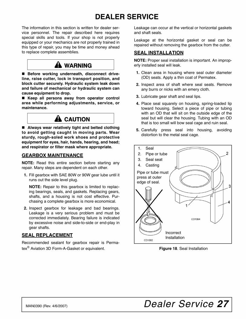
SEAL INSTALLATION
NOTE: Proper seal installation is important. An improp-erly installed seal will leak.
1. Clean area in housing where seal outer diameter(OD) seats. Apply a thin coat of Permatex.
2. Inspect area of shaft where seal seats. Removeany burrs or nicks with an emery cloth.
3. Lubricate gear shaft and seal lips.
4. Place seal squarely on housing, spring-loaded liptoward housing. Select a piece of pipe or tubingwith an OD that will sit on the outside edge of theseal but will clear the housing. Tubing with an ODthat is too small will bow seal cage and ruin seal.
5. Carefully press seal into housing, avoidingdistortion to the metal seal cage.
Figure 18. Seal Installation
�������
CAUTION
1. Seal2. Pipe or tube3. Seal seat4. Casting
Pipe or tube mustpress at outeredge of seal.
IncorrectInstallation
28 Dealer Service MAN0390 (Rev. 4/6/2007)
VERTICAL SHAFT SEAL REPAIR (SPINDLE BOX)
Refer to Figure 19.
1. Disconnect and remove the driveline from thegearbox.
2. Remove vent plug (3) and siphon gear lube fromhousing through this opening.
3. Remove crossbar (see Crossbar removal on page33).
4. Remove vertical shaft seal (16). Replace with newseal (see Seal Installation on page 27).
Vertical seal should be recessed in housing. Hori-zontal seal should be pressed flush with outside ofhousing.
NOTE: Distortion to seal cage or damage to seallip will cause seal to leak.
5. Fill gearbox with SAE 80W or 90W gear lube until itruns out the level plug.
6. Remove and replace any seal damaged ininstallation.
HORIZONTAL SHAFT SEAL REPAIR
Refer to Figure 19.
1. Disconnect and remove the driveline from thegearbox.
2. Remove vent plug (3) and siphon gear lube fromhousing through this opening.
3. If the leak occurred at either end of horizontal shaft(spindle gearbox), remove oil cap (24) and/or oilseal (10). For splitter gearbox (Figure 20) use oilseals (11) and (17). Replace with new one (refer toSeal Installation, page 27).
4. Fill gearbox with SAE 80W or 90W gear lube until itruns out the level plug.
SPINDLE GEARBOX REPAIR
NOTE: Replacing gears, shafts, bearings, and sealsmay not be cost effective. Purchasing a complete gear-box may be more economical.
REMOVE GEARBOX FROM CUTTER
Refer to Figure 19.
1. Disconnect and remove the driveline from thegearbox.
2. Remove vent plug (3) and siphon gear lube fromhousing through this opening.
3. Remove cotter pin, washer, and nut from verticalshaft and remove crossbar (see Crossbar removal,page 33).
4. Remove the four bolts that attach gearbox to cutterand remove gearbox. Gearbox is heavy; do notattempt to move without mechanical assistance.
DISASSEMBLE GEARBOX
Refer to Figure 19.
1. Remove 3/8" plug from side of gearbox and pourout gear oil.
2. Remove oil cap (24) (to be replaced).
3. Remove snap ring (9) and shim (5) from input shaft(11).
4. Support gearbox in hand press and push on inputshaft (11) to remove bearing (23).
5. Remove top cover (4) from housing. Remove gear(6) from inside housing.
6. Remove oil seal (10) from front of housing (to bereplaced).
7. Remove snap ring (9) and shim (5) from front ofhousing (1).
8. Remove input bearing (7) by using a punch andhammer from outside of housing.
9. Support housing in vise in a horizontal position.
10. The castle nut (21), cotter pin (8), and washer (20)are already removed with the stumpjumper/crossbar. Remove the protective screen(17) and seal (16).
11. Remove cotter pin (18), castle nut (12), andwasher (25) from output shaft (19).
12. Remove output shaft (19) by using a punch andhammer and tap on top to drive down.
13. Remove gear (5) and shim (15) from insidehousing.
14. Remove bearing (15) by using a punch andhammer from the top, outside the housing.
15. Support housing upside down (top cover surface)and remove bearing (15) by using a punch andhammer from the bottom side of the housing.
16. Inspect gears for broken teeth and wear. Somewear is normal and will show on loaded side.Forged gear surfaces are rough when new. Checkthat wear pattern is smooth.
17. Inspect vertical and horizontal shafts for grooves,nicks, or bumps in the areas where the seals seat.Resurface any damage with emery cloth.
18. Inspect housing and caps for cracks or otherdamage.
Dealer Service 29MAN0390 (Rev. 4/6/2007)
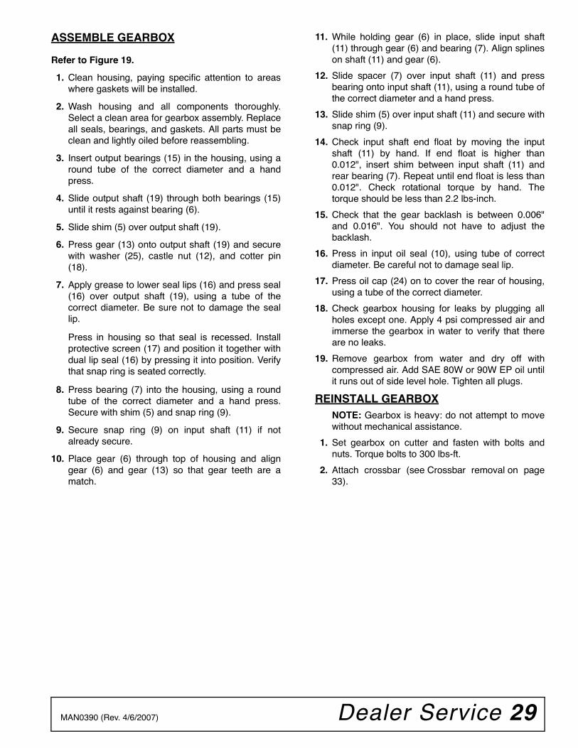
ASSEMBLE GEARBOX
Refer to Figure 19.
1. Clean housing, paying specific attention to areaswhere gaskets will be installed.
2. Wash housing and all components thoroughly.Select a clean area for gearbox assembly. Replaceall seals, bearings, and gaskets. All parts must beclean and lightly oiled before reassembling.
3. Insert output bearings (15) in the housing, using around tube of the correct diameter and a handpress.
4. Slide output shaft (19) through both bearings (15)until it rests against bearing (6).
5. Slide shim (5) over output shaft (19).
6. Press gear (13) onto output shaft (19) and securewith washer (25), castle nut (12), and cotter pin(18).
7. Apply grease to lower seal lips (16) and press seal(16) over output shaft (19), using a tube of thecorrect diameter. Be sure not to damage the seallip.
Press in housing so that seal is recessed. Installprotective screen (17) and position it together withdual lip seal (16) by pressing it into position. Verifythat snap ring is seated correctly.
8. Press bearing (7) into the housing, using a roundtube of the correct diameter and a hand press.Secure with shim (5) and snap ring (9).
9. Secure snap ring (9) on input shaft (11) if notalready secure.
10. Place gear (6) through top of housing and aligngear (6) and gear (13) so that gear teeth are amatch.
11. While holding gear (6) in place, slide input shaft(11) through gear (6) and bearing (7). Align splineson shaft (11) and gear (6).
12. Slide spacer (7) over input shaft (11) and pressbearing onto input shaft (11), using a round tube ofthe correct diameter and a hand press.
13. Slide shim (5) over input shaft (11) and secure withsnap ring (9).
14. Check input shaft end float by moving the inputshaft (11) by hand. If end float is higher than0.012", insert shim between input shaft (11) andrear bearing (7). Repeat until end float is less than0.012". Check rotational torque by hand. Thetorque should be less than 2.2 lbs-inch.
15. Check that the gear backlash is between 0.006"and 0.016". You should not have to adjust thebacklash.
16. Press in input oil seal (10), using tube of correctdiameter. Be careful not to damage seal lip.
17. Press oil cap (24) on to cover the rear of housing,using a tube of the correct diameter.
18. Check gearbox housing for leaks by plugging allholes except one. Apply 4 psi compressed air andimmerse the gearbox in water to verify that thereare no leaks.
19. Remove gearbox from water and dry off withcompressed air. Add SAE 80W or 90W EP oil untilit runs out of side level hole. Tighten all plugs.
REINSTALL GEARBOXNOTE: Gearbox is heavy: do not attempt to movewithout mechanical assistance.
1. Set gearbox on cutter and fasten with bolts andnuts. Torque bolts to 300 lbs-ft.
2. Attach crossbar (see Crossbar removal on page33).
30 Dealer Service MAN0390 (Rev. 4/6/2007)
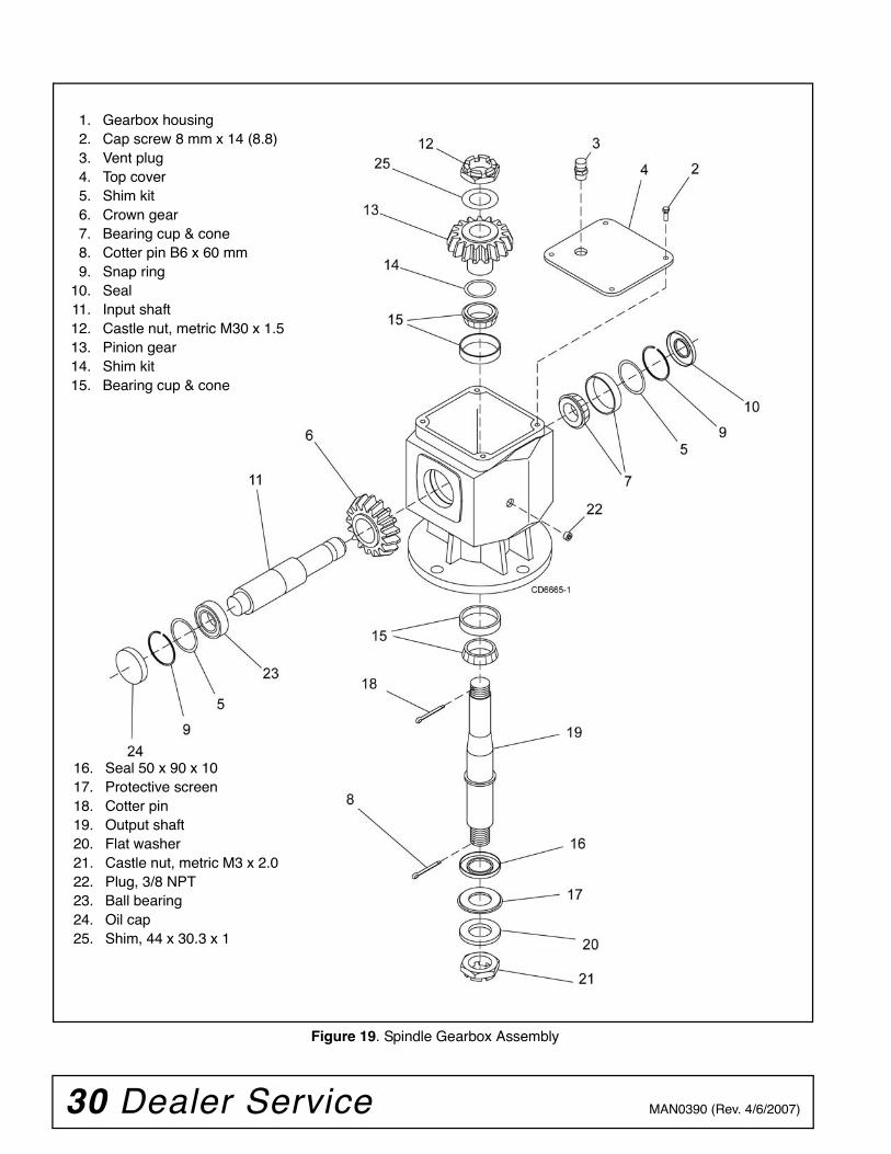
Figure 19. Spindle Gearbox Assembly
16. Seal 50 x 90 x 1017. Protective screen18. Cotter pin19. Output shaft20. Flat washer 21. Castle nut, metric M3 x 2.022. Plug, 3/8 NPT23. Ball bearing24. Oil cap25. Shim, 44 x 30.3 x 1
1. Gearbox housing2. Cap screw 8 mm x 14 (8.8)3. Vent plug4. Top cover5. Shim kit6. Crown gear7. Bearing cup & cone8. Cotter pin B6 x 60 mm9. Snap ring
10. Seal11. Input shaft12. Castle nut, metric M30 x 1.513. Pinion gear14. Shim kit15. Bearing cup & cone
Dealer Service 31MAN0390 (Rev. 4/6/2007)
SPLITTER GEARBOX REPAIR
NOTE: Replacing gears, shafts, bearings, and sealsmay not be cost effective. Purchasing a complete gear-box may be more economical.
REMOVE GEARBOX FROM CUTTER
1. Disconnect driveline from the tractor PTO andremove it from center gearbox.
2. Remove vent plug (6) and siphon gear lube fromhousing through this opening.
3. Disconnect and remove flex coupler drivelines fromside of gearbox by:
a. Removing cap screws and hex nuts from drive-line.
b. Loosen set screws from flex coupler yoke.
c. Slide flex coupler yoke from gearbox shaft.
4. Remove the four bolts that attach gearbox to cutterand remove gearbox. Gearbox is heavy; do notattempt to move without mechanical assistance.
DISASSEMBLE SPLITTER GEARBOX
Refer to Figure 20.
1. Remove breather plug from top of gearbox.
2. Remove plug (19) from side of input housing (1)and pour out gear oil.
3. Remove eight cap screws (3) from around inputhousing (15). Remove input shaft assembly andhousing.
4. Remove oil seals (11) (to be replaced) from bothsides of cross shaft (4).
5. Remove eight cap screws (3) from around gearboxcover (12) and remove cross shaft (4) fromgearbox.
6. Disassemble shims (5 & 18), spacer (20), bearings(16 & 13), and crown gear (7) from cross shaft.
7. Support housing in a vise and remove bearingcones (16) by using a punch and hammer to drivebearing cone out.
8. Support cover (12) in a vise and remove bearingcups (13) by using a punch and hammer to drivebearing cone out.
9. Remove lock nut (2) from end of input shaft (14).
10. Support input housing in a handpress and pushinput shaft (14) out of housing.
11. Support housing in a vise and remove bearingcups (13 & 16) by using a punch and hammer todrive bearing cones out.
12. Inspect gears for broken teeth and wear. Somewear is normal and will show on loaded side.Forged gear surfaces are rough when new. Checkthat wear pattern is smooth.
13. Inspect input and cross shafts for grooves, nicks,or bumps in the areas where the seals seat.Resurface any damage with emery cloth.
14. Inspect housing and caps for cracks or damage.
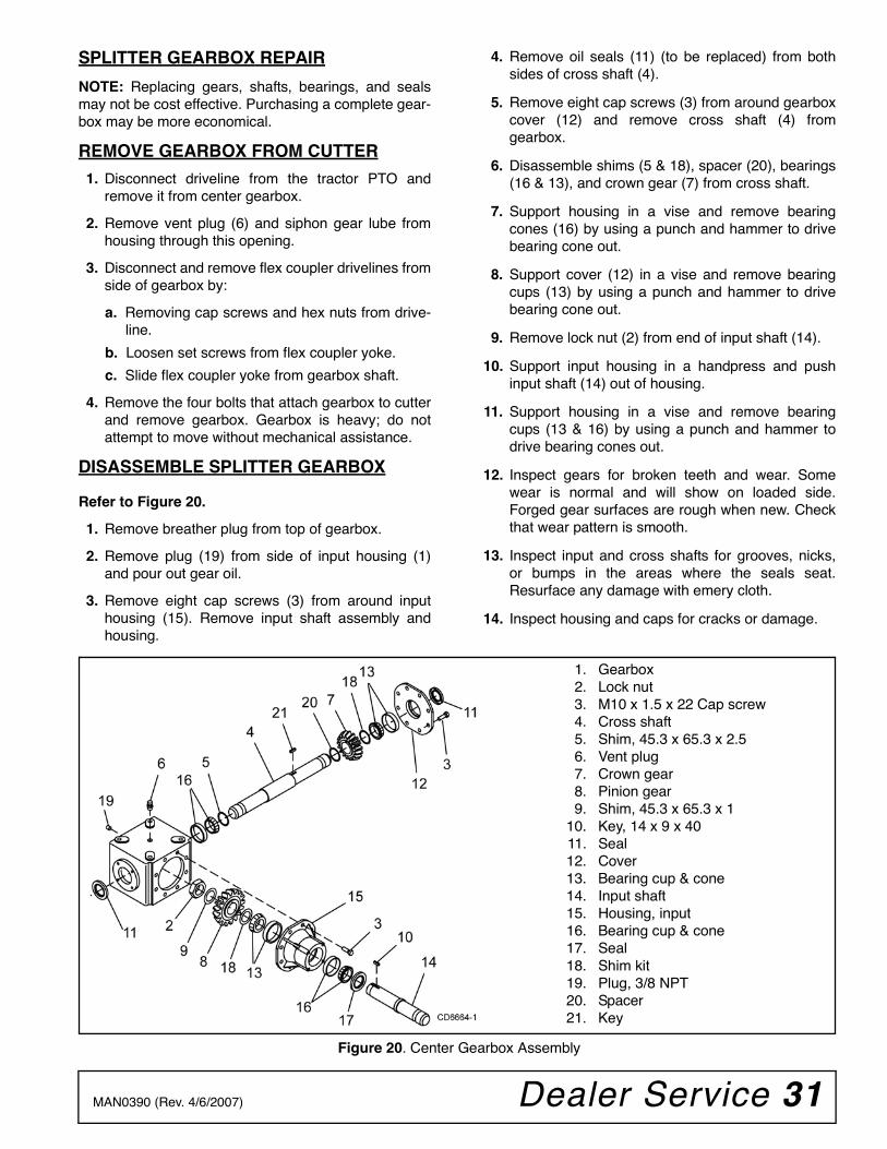
Figure 20. Center Gearbox Assembly
1. Gearbox2. Lock nut3. M10 x 1.5 x 22 Cap screw4. Cross shaft5. Shim, 45.3 x 65.3 x 2.56. Vent plug7. Crown gear8. Pinion gear9. Shim, 45.3 x 65.3 x 1
10. Key, 14 x 9 x 4011. Seal12. Cover13. Bearing cup & cone14. Input shaft15. Housing, input16. Bearing cup & cone17. Seal18. Shim kit19. Plug, 3/8 NPT20. Spacer21. Key
32 Dealer Service MAN0390 (Rev. 4/6/2007)
ASSEMBLE GEARBOX
Refer to Figure 20.
1. Clean housing, paying specific attention to areaswhere gaskets will be installed.
2. Wash housing and all components thoroughly.Select a clean area for gearbox assembly. Replaceall seals, bearings, and gaskets. All parts must beclean and lightly oiled before reassembling.
3. Install new bearing cup (16) in gearbox housingand bearing cup (13) in cover if these parts werepreviously removed.
4. Place bearing (16) and shim (5) on end of crossshaft (4), and insert shaft into housing.
5. Install spacer (20), key (21), crown gear (7), shim(18), and bearing (13) on opposite end of crossshaft.
6. Place cover (12) over bearings (13) and secureinto position using eight cap screws (3). Torque capscrews to 29 lbs-ft.
7. Place seal (11) over cross shaft and press intohousing. Use a round tube the same diameter ofthe seal and a handpress. Repeat process onopposite side of gearbox.
8. Install new bearing cup (16 & 13) into input housingif these parts were previously removed.
9. Place bearing (16) over end of input shaft (14) andinsert shaft into front of input housing.
10. Place seal (17) over shaft and press into housing.Use a round tube the same diameter of the sealand a handpress.
11. Install bearing (13), shim (18), pinion gear (8), key(10), shim (9) over opposite end of input shaft (14).
12. Secure parts together using lock nut (2). Tightenlock nut (2) until shaft rolling torque is 3 to 9 lbs-inch.
13. Insert input housing assembly into front of gearboxhousing and align teeth of the two gears. Securewith cap screws (3). Torque cap screws to 29 lbs-ft.
14. Check gear backlash; it should be .006" to .017" atouter tooth.
15. Check gearbox housing for leaks by plugging allholes except one. Apply 4 psi compressed air andimmerse the gearbox in water to verify that thereare no leaks.
16. Remove gearbox from water and dry off withcompressed air. Add SAE 80W or 90W EP oil untilit runs out of the lower level hole in front cover.Tighten all plugs.
REINSTALL GEARBOX
NOTE: Gearbox is heavy: do not attempt to movewithout mechanical assistance.
1. Install flex coupler driveline between sidegearboxes and center gearbox.
2. Set gearbox on cutter and fasten with bolts andnuts. Torque bolts to 300 lbs-ft.
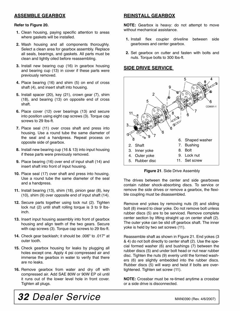
SIDE DRIVE SERVICE
Figure 21. Side Drive Assembly
The drives between the center and side gearboxescontain rubber shock-absorbing discs. To service orremove the side drives or remove a gearbox, the flexi-ble coupling must be disassembled.
Remove end yokes by removing nuts (9) and slidingbolt (8) inward to clear yoke. Do not remove bolt unlessrubber discs (5) are to be serviced. Remove completecenter section by lifting straight up on center shaft (2).The outer yoke can be slid off gearbox shaft. The inneryoke is held by two set screws (11).
Reassemble shaft as shown in Figure 21. End yokes (3& 4) do not bolt directly to center shaft (2). Use the spe-cial formed washer (6) and bushings (7) between therubber discs (5) and under bolt head or nut near rubberdisc. Tighten the nuts (9) evenly until the formed wash-ers (6) are slightly embedded into the rubber discs.Rubber discs (5) will warp and twist if bolts are over-tightened. Tighten set screw (11).
NOTE: Crossbar must be re-timed anytime a crossbaror a side drive is disconnected.
6. Shaped washer7. Bushing8. Bolt9. Lock nut
11. Set screw
2. Shaft3. Inner yoke4. Outer yoke5. Rubber disc
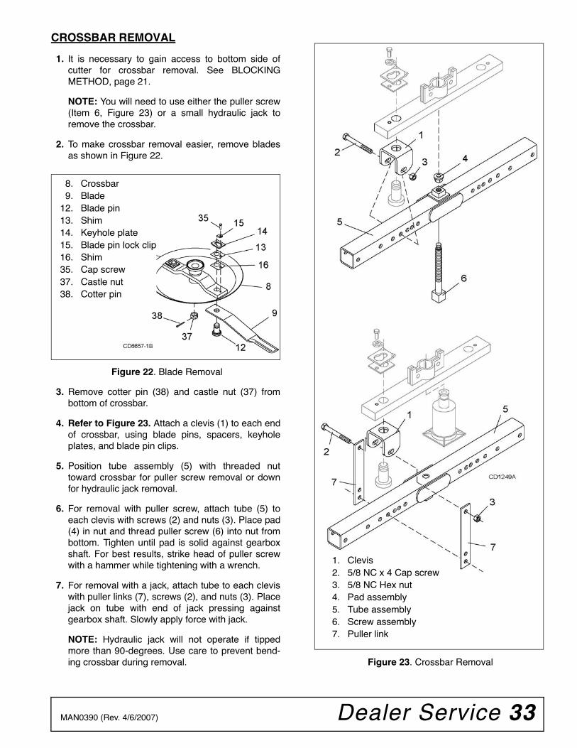
Dealer Service 33MAN0390 (Rev. 4/6/2007)
CROSSBAR REMOVAL
1. It is necessary to gain access to bottom side ofcutter for crossbar removal. See BLOCKINGMETHOD, page 21.
NOTE: You will need to use either the puller screw(Item 6, Figure 23) or a small hydraulic jack toremove the crossbar.
2. To make crossbar removal easier, remove bladesas shown in Figure 22.
Figure 22. Blade Removal
3. Remove cotter pin (38) and castle nut (37) frombottom of crossbar.
4. Refer to Figure 23. Attach a clevis (1) to each endof crossbar, using blade pins, spacers, keyholeplates, and blade pin clips.
5. Position tube assembly (5) with threaded nuttoward crossbar for puller screw removal or downfor hydraulic jack removal.
6. For removal with puller screw, attach tube (5) toeach clevis with screws (2) and nuts (3). Place pad(4) in nut and thread puller screw (6) into nut frombottom. Tighten until pad is solid against gearboxshaft. For best results, strike head of puller screwwith a hammer while tightening with a wrench.
7. For removal with a jack, attach tube to each cleviswith puller links (7), screws (2), and nuts (3). Placejack on tube with end of jack pressing againstgearbox shaft. Slowly apply force with jack.
NOTE: Hydraulic jack will not operate if tippedmore than 90-degrees. Use care to prevent bend-ing crossbar during removal. Figure 23. Crossbar Removal
8. Crossbar9. Blade
12. Blade pin13. Shim14. Keyhole plate15. Blade pin lock clip16. Shim35. Cap screw37. Castle nut38. Cotter pin
1. Clevis2. 5/8 NC x 4 Cap screw3. 5/8 NC Hex nut4. Pad assembly5. Tube assembly6. Screw assembly7. Puller link
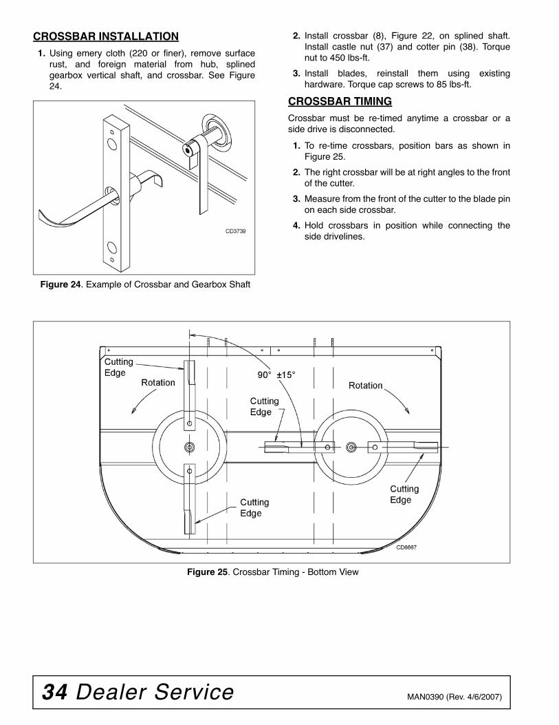
34 Dealer Service MAN0390 (Rev. 4/6/2007)
CROSSBAR INSTALLATION1. Using emery cloth (220 or finer), remove surface
rust, and foreign material from hub, splinedgearbox vertical shaft, and crossbar. See Figure24.
Figure 24. Example of Crossbar and Gearbox Shaft
2. Install crossbar (8), Figure 22, on splined shaft.Install castle nut (37) and cotter pin (38). Torquenut to 450 lbs-ft.
3. Install blades, reinstall them using existinghardware. Torque cap screws to 85 lbs-ft.
CROSSBAR TIMINGCrossbar must be re-timed anytime a crossbar or aside drive is disconnected.
1. To re-time crossbars, position bars as shown inFigure 25.
2. The right crossbar will be at right angles to the frontof the cutter.
3. Measure from the front of the cutter to the blade pinon each side crossbar.
4. Hold crossbars in position while connecting theside drivelines.
Figure 25. Crossbar Timing - Bottom View
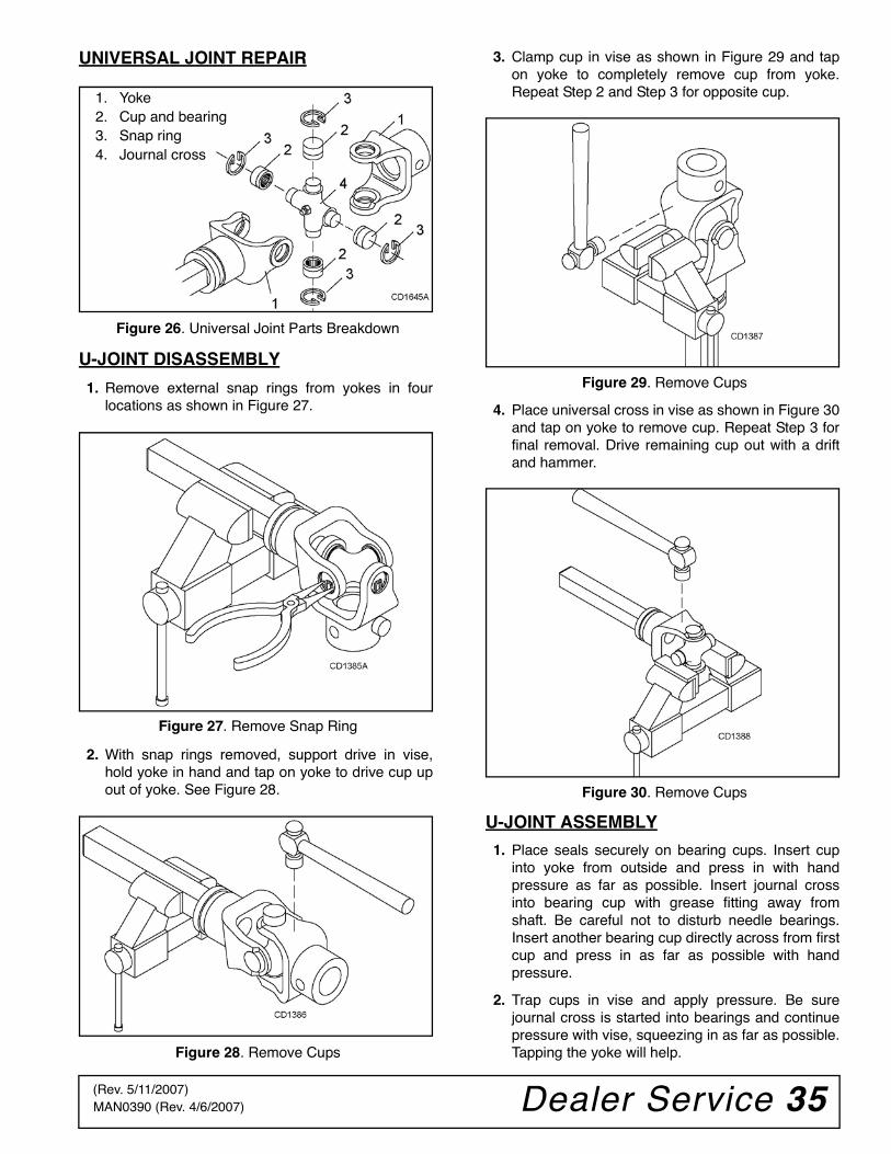
Dealer Service 35MAN0390 (Rev. 4/6/2007)
UNIVERSAL JOINT REPAIR
Figure 26. Universal Joint Parts Breakdown
U-JOINT DISASSEMBLY
1. Remove external snap rings from yokes in fourlocations as shown in Figure 27.
Figure 27. Remove Snap Ring
2. With snap rings removed, support drive in vise,hold yoke in hand and tap on yoke to drive cup upout of yoke. See Figure 28.
Figure 28. Remove Cups
3. Clamp cup in vise as shown in Figure 29 and tapon yoke to completely remove cup from yoke.Repeat Step 2 and Step 3 for opposite cup.
Figure 29. Remove Cups
4. Place universal cross in vise as shown in Figure 30and tap on yoke to remove cup. Repeat Step 3 forfinal removal. Drive remaining cup out with a driftand hammer.
Figure 30. Remove Cups
U-JOINT ASSEMBLY
1. Place seals securely on bearing cups. Insert cupinto yoke from outside and press in with handpressure as far as possible. Insert journal crossinto bearing cup with grease fitting away fromshaft. Be careful not to disturb needle bearings.Insert another bearing cup directly across from firstcup and press in as far as possible with handpressure.
2. Trap cups in vise and apply pressure. Be surejournal cross is started into bearings and continuepressure with vise, squeezing in as far as possible.Tapping the yoke will help.
1. Yoke2. Cup and bearing3. Snap ring4. Journal cross
(Rev. 5/11/2007)
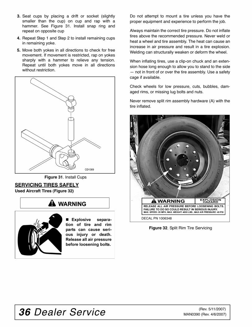
36 Dealer Service MAN0390 (Rev. 4/6/2007)
3. Seat cups by placing a drift or socket (slightlysmaller than the cup) on cup and rap with ahammer. See Figure 31. Install snap ring andrepeat on opposite cup
4. Repeat Step 1 and Step 2 to install remaining cupsin remaining yoke.
5. Move both yokes in all directions to check for freemovement. If movement is restricted, rap on yokessharply with a hammer to relieve any tension.Repeat until both yokes move in all directionswithout restriction.
Figure 31. Install Cups
SERVICING TIRES SAFELYUsed Aircraft Tires (Figure 32)
Do not attempt to mount a tire unless you have theproper equipment and experience to perform the job.
Always maintain the correct tire pressure. Do not inflatetires above the recommended pressure. Never weld orheat a wheel and tire assembly. The heat can cause anincrease in air pressure and result in a tire explosion.Welding can structurally weaken or deform the wheel.
When inflating tires, use a clip-on chuck and an exten-sion hose long enough to allow you to stand to the side— not in front of or over the tire assembly. Use a safetycage if available.
Check wheels for low pressure, cuts, bubbles, dam-aged rims, or missing lug bolts and nuts.
Never remove split rim assembly hardware (A) with thetire inflated.
Figure 32. Split Rim Tire Servicing
WARNING
A
DECAL PN 1006348
(Rev. 5/11/2007)
Assembly 37MAN0390 (Rev. 4/6/2007)
ASSEMBLY INSTRUCTIONSDEALER SET-UP INSTRUCTIONS
Full chain or rubber shielding must be installedwhen operating in populated areas or other areaswhere thrown objects could injure people or dam-age property.
• If this machine is not equipped with full chainor rubber shielding, operation must be stoppedwhen anyone comes within 300 feet (92 m).• This shielding is designed to reduce the riskof thrown objects. The mower deck and protec-tive devices cannot prevent all objects fromescaping the blade enclosure in every mowingcondition. It is possible for objects to ricochetand escape, traveling as much as 300 feet (92 m).
Make sure spring-activated locking pin or collarslides freely and is seated firmly in tractor PTOspline groove.
Always wear relatively tight and belted clothingto avoid getting caught in moving parts. Wearsturdy, rough-soled work shoes and protectiveequipment for eyes, hair, hands, hearing, and head;and respirator or filter mask where appropriate.
These instructions are for the assembly of the DS96and DS120 mounted and pull-type cutters. Many of theprocedures apply to all units. When an instructionapplies to a specific unit, the section heading willindicate which unit. Assembly of options may not applyto all units.
Assembly of this cutter is the responsibility of theWoods dealer. It should be delivered to the ownercompletely assembled, lubricated, and adjusted fornormal cutting conditions.
The cutter is shipped partially assembled. Assemblywill be easier if aligned and loosely assembled beforetightening hardware. Recommended torque values forhardware are located in the Bolt Torque Chart, page74.
Select a suitable working area. A smooth hard surface,such as concrete, will make assembly much quicker.Open parts boxes and lay out parts and hardware tomake location easy. Refer to illustrations, accompany-ing text, parts lists and exploded view drawings.
Complete check lists on page 49 when you have com-pleted the assembly.
ASSEMBLE - DS96 PULL-TYPE CUTTER REAR HALF
Refer to Figure 33.
Place jackstands under cutter to raise it off the groundto provide clearance when assembling cutter. See“BLOCKING METHOD” on page 21 for jackstandplacement.
Install Rear Tailwheel1. Attach tailwheel (1) to the rear of the cutter using
two clevis pins (13) and cotter pins (35).
2. Insert wheel hubs (2) to the outer mounting tubesof tailwheel. Secure with cap screws (33) andflange lock nut (34). NOTE: Inner mounting tubesare for adding a second set of wheels.
3. Attach solid or aircraft tires to wheel hubs usingfour cap screws (31) and lock washers (32).
4. Attach rims and pneumatic tires (pneumatic tiresare not furnished) to wheel hubs using four wheelbolts (30).
5. Attach tire and rim with 1/2" lug nuts supplied with(2).
Install Attitude RodSlide attitude rod (5) under left spindle drivelineand through pivot block on the tailwheel. Looselyinstall spacers (6), washers (37) and two hex nuts(36).
Install Height Adjustment Device
Ratchet
Install ratchet (12) between cylinder lug on tail-wheel and lug on deck. Secure with pins suppliedwith ratchet.
Cylinder
1. Place hydraulic cylinder (8) between lug ontailwheel and lug on deck.
2. Secure to deck lug using pin (15) and two cotterpins (35).
3. Extend cylinder rod, place transport lock bracket(7) over cylinder rod end and lug on tailwheel.
4. Align holes of cylinder rod, transport lock bracket(7) and lug on tailwheel. Secure assembly usingpin (16) and two cotter pins (35).
������
�������
CAUTION
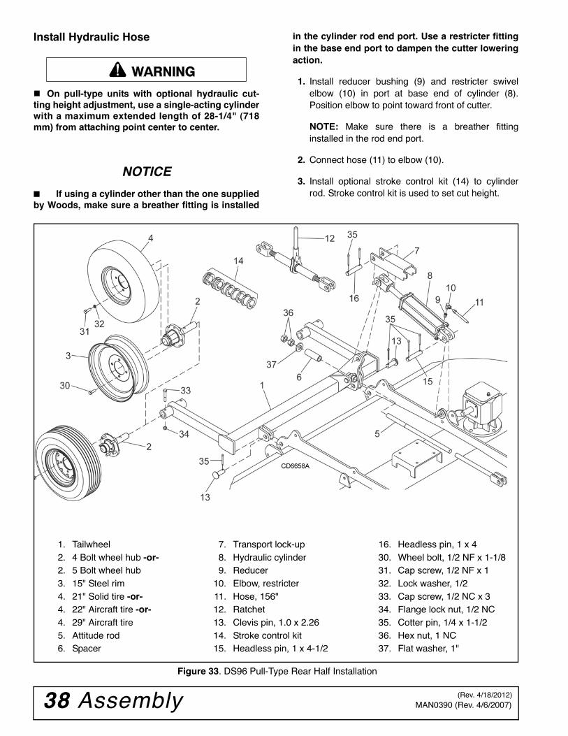
38 Assembly MAN0390 (Rev. 4/6/2007)
Install Hydraulic Hose
On pull-type units with optional hydraulic cut-ting height adjustment, use a single-acting cylinderwith a maximum extended length of 28-1/4" (718mm) from attaching point center to center.
NOTICE
■ If using a cylinder other than the one suppliedby Woods, make sure a breather fitting is installed
in the cylinder rod end port. Use a restricter fittingin the base end port to dampen the cutter loweringaction.
1. Install reducer bushing (9) and restricter swivelelbow (10) in port at base end of cylinder (8).Position elbow to point toward front of cutter.
NOTE: Make sure there is a breather fittinginstalled in the rod end port.
2. Connect hose (11) to elbow (10).
3. Install optional stroke control kit (14) to cylinderrod. Stroke control kit is used to set cut height.
Figure 33. DS96 Pull-Type Rear Half Installation
�������
1. Tailwheel2. 4 Bolt wheel hub -or-2. 5 Bolt wheel hub3. 15" Steel rim4. 21" Solid tire -or-4. 22" Aircraft tire -or-4. 29" Aircraft tire5. Attitude rod6. Spacer
7. Transport lock-up8. Hydraulic cylinder9. Reducer
10. Elbow, restricter11. Hose, 156"12. Ratchet 13. Clevis pin, 1.0 x 2.2614. Stroke control kit15. Headless pin, 1 x 4-1/2
16. Headless pin, 1 x 430. Wheel bolt, 1/2 NF x 1-1/831. Cap screw, 1/2 NF x 132. Lock washer, 1/233. Cap screw, 1/2 NC x 334. Flange lock nut, 1/2 NC35. Cotter pin, 1/4 x 1-1/236. Hex nut, 1 NC37. Flat washer, 1"
(Rev. 4/18/2012)
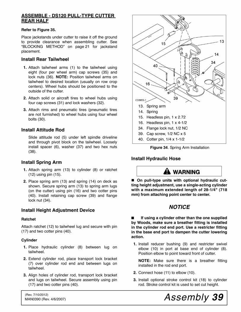
Assembly 39MAN0390 (Rev. 4/6/2007)
ASSEMBLE - DS120 PULL-TYPE CUTTER REAR HALF
Refer to Figure 35.
Place jackstands under cutter to raise it off the groundto provide clearance when assembling cutter. See“BLOCKING METHOD” on page 21 for jackstandplacement.
Install Rear Tailwheel
1. Attach tailwheel arms (1) to the tailwheel usingeight (four per wheel arm) cap screws (35) andlock nuts (36). NOTE: Position tailwheel arms ontailwheel to desired location (usually on row cropcenters). Wheel hubs should be positioned to theoutside of the cutter.
2. Attach solid or aircraft tires to wheel hubs usingfour cap screws (31) and lock washers (32).
3. Attach rims and pneumatic tires (pneumatic tiresare not furnished) to wheel hubs using four wheelbolts (30).
Install Attitude Rod
Slide attitude rod (5) under left spindle drivelineand through pivot block on the tailwheel. Looselyinstall spacer (6), washer (37) and two hex nuts(38).
Install Spring Arm
1. Attach spring arm (13) to cylinder (8) or ratchet(12) using pin (15).
2. Place spring arm (13) and spring (14) on deck asshown. Secure spring arm (13) to spring arm lugs(on the cutter) using pin (16) and two cotter pins(40). Install retaining cap screw (39) and flangelock nut (34).
Install Height Adjustment Device
Ratchet
Attach ratchet (12) to tailwheel lug and secure with pin(17) and two cotter pins (40).
Cylinder
1. Place hydraulic cylinder (8) between lug ontailwheel.
2. Extend cylinder rod, place transport lock bracket(7) over cylinder rod end and between lugs ontailwheel.
3. Align holes of cylinder rod, transport lock bracketand lugs on tailwheel. Secure assembly using pin(17) and two cotter pins (40).
Figure 34. Spring Arm Installation
Install Hydraulic Hose
On pull-type units with optional hydraulic cut-ting height adjustment, use a single-acting cylinderwith a maximum extended length of 28-1/4" (718mm) from attaching point center to center.
NOTICE
■ If using a cylinder other than the one suppliedby Woods, make sure a breather fitting is installedin the cylinder rod end port. Use a restricter fittingin the base end port to dampen the cutter loweringaction.
1. Install reducer bushing (9) and restricter swivelelbow (10) in port at base end of cylinder (8).Position elbow to point toward front of cutter.
NOTE: Make sure there is a breather fittinginstalled in the rod end port.
2. Connect hose (11) to elbow (10).
3. Install optional stroke control kit (18) to cylinderrod. Stroke control kit is used to set cut height.
13. Spring arm14. Spring15. Headless pin, 1 x 2.7216. Headless pin, 1 x 4-1/234. Flange lock nut, 1/2 NC39. Cap screw, 1/2 NC x 540. Cotter pin, 1/4 x 1-1/2
�������
(Rev. 7/10/2012)
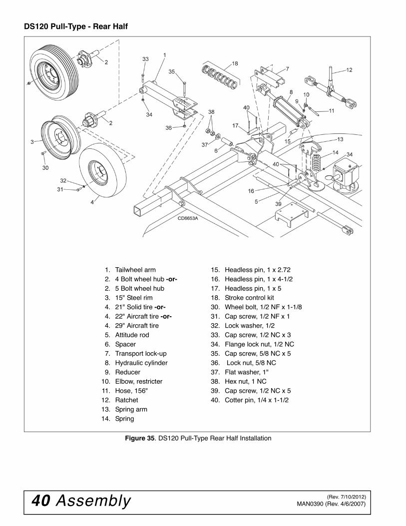
40 Assembly MAN0390 (Rev. 4/6/2007)
DS120 Pull-Type - Rear Half
Figure 35. DS120 Pull-Type Rear Half Installation
1. Tailwheel arm2. 4 Bolt wheel hub -or-2. 5 Bolt wheel hub3. 15" Steel rim4. 21" Solid tire -or-4. 22" Aircraft tire -or-4. 29" Aircraft tire5. Attitude rod6. Spacer7. Transport lock-up8. Hydraulic cylinder9. Reducer
10. Elbow, restricter11. Hose, 156"12. Ratchet 13. Spring arm14. Spring
15. Headless pin, 1 x 2.7216. Headless pin, 1 x 4-1/217. Headless pin, 1 x 518. Stroke control kit30. Wheel bolt, 1/2 NF x 1-1/831. Cap screw, 1/2 NF x 132. Lock washer, 1/233. Cap screw, 1/2 NC x 334. Flange lock nut, 1/2 NC35. Cap screw, 5/8 NC x 536. Lock nut, 5/8 NC37. Flat washer, 1"38. Hex nut, 1 NC39. Cap screw, 1/2 NC x 540. Cotter pin, 1/4 x 1-1/2
(Rev. 7/10/2012)
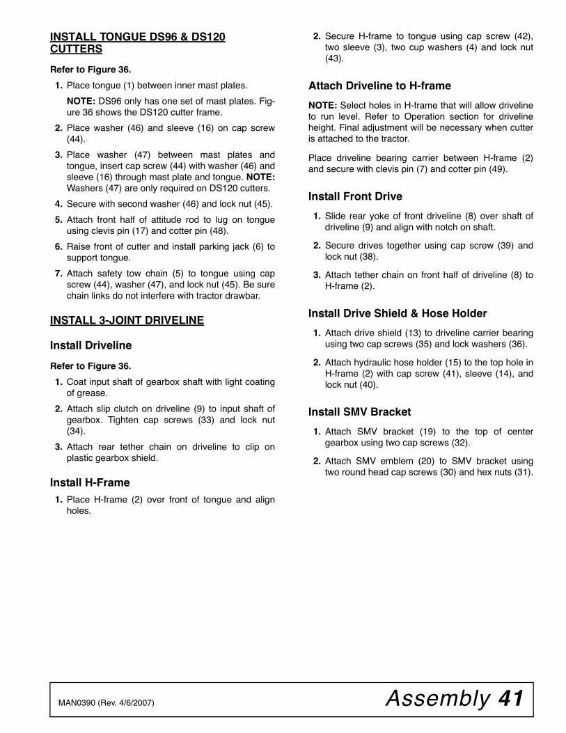
Assembly 41MAN0390 (Rev. 4/6/2007)
INSTALL TONGUE DS96 & DS120CUTTERS
Refer to Figure 36.
1. Place tongue (1) between inner mast plates.
NOTE: DS96 only has one set of mast plates. Fig-ure 36 shows the DS120 cutter frame.
2. Place washer (46) and sleeve (16) on cap screw(44).
3. Place washer (47) between mast plates andtongue, insert cap screw (44) with washer (46) andsleeve (16) through mast plate and tongue. NOTE:Washers (47) are only required on DS120 cutters.
4. Secure with second washer (46) and lock nut (45).
5. Attach front half of attitude rod to lug on tongueusing clevis pin (17) and cotter pin (48).
6. Raise front of cutter and install parking jack (6) tosupport tongue.
7. Attach safety tow chain (5) to tongue using capscrew (44), washer (47), and lock nut (45). Be surechain links do not interfere with tractor drawbar.
INSTALL 3-JOINT DRIVELINE
Install Driveline
Refer to Figure 36.
1. Coat input shaft of gearbox shaft with light coatingof grease.
2. Attach slip clutch on driveline (9) to input shaft ofgearbox. Tighten cap screws (33) and lock nut(34).
3. Attach rear tether chain on driveline to clip onplastic gearbox shield.
Install H-Frame1. Place H-frame (2) over front of tongue and align
holes.
2. Secure H-frame to tongue using cap screw (42),two sleeve (3), two cup washers (4) and lock nut(43).
Attach Driveline to H-frame
NOTE: Select holes in H-frame that will allow drivelineto run level. Refer to Operation section for drivelineheight. Final adjustment will be necessary when cutteris attached to the tractor.
Place driveline bearing carrier between H-frame (2)and secure with clevis pin (7) and cotter pin (49).
Install Front Drive
1. Slide rear yoke of front driveline (8) over shaft ofdriveline (9) and align with notch on shaft.
2. Secure drives together using cap screw (39) andlock nut (38).
3. Attach tether chain on front half of driveline (8) toH-frame (2).
Install Drive Shield & Hose Holder
1. Attach drive shield (13) to driveline carrier bearingusing two cap screws (35) and lock washers (36).
2. Attach hydraulic hose holder (15) to the top hole inH-frame (2) with cap screw (41), sleeve (14), andlock nut (40).
Install SMV Bracket
1. Attach SMV bracket (19) to the top of centergearbox using two cap screws (32).
2. Attach SMV emblem (20) to SMV bracket usingtwo round head cap screws (30) and hex nuts (31).
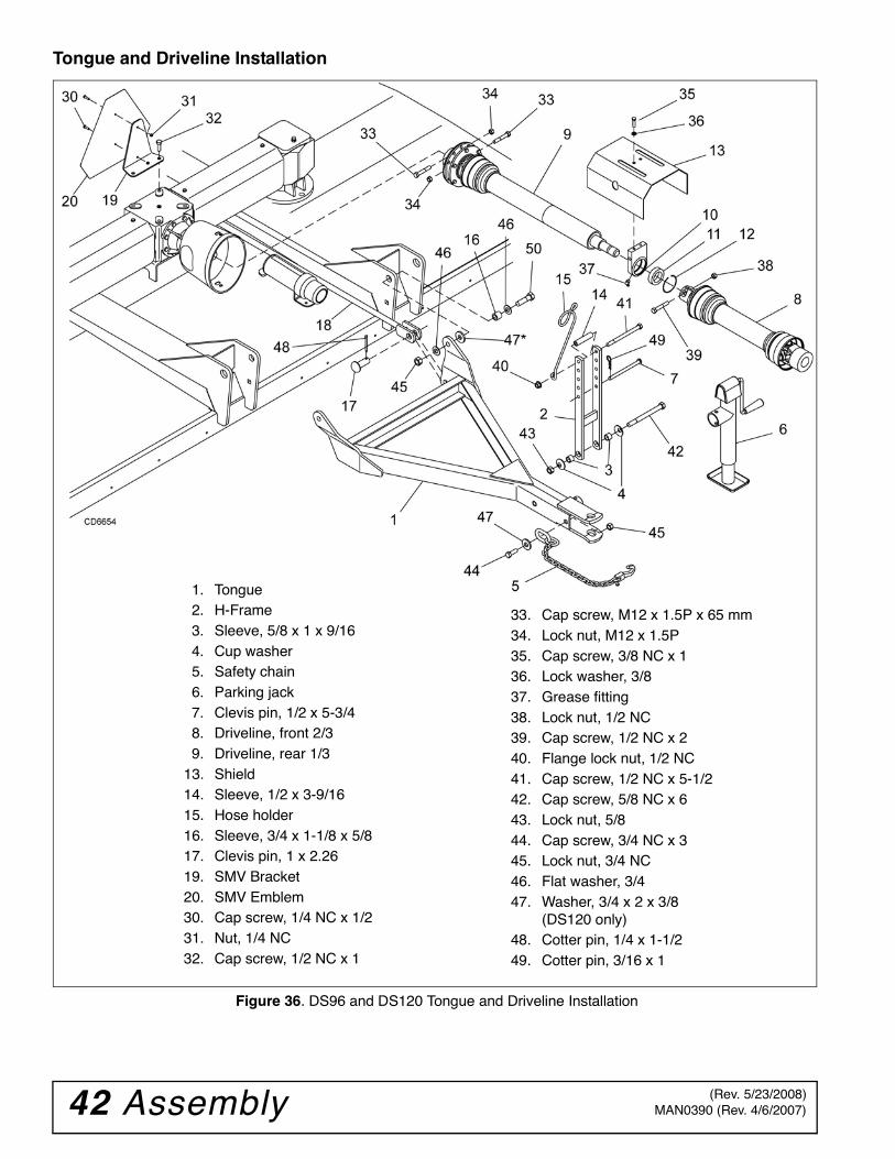
42 Assembly MAN0390 (Rev. 4/6/2007)
Tongue and Driveline Installation
Figure 36. DS96 and DS120 Tongue and Driveline Installation
1. Tongue2. H-Frame3. Sleeve, 5/8 x 1 x 9/164. Cup washer5. Safety chain6. Parking jack7. Clevis pin, 1/2 x 5-3/48. Driveline, front 2/39. Driveline, rear 1/3
13. Shield14. Sleeve, 1/2 x 3-9/1615. Hose holder16. Sleeve, 3/4 x 1-1/8 x 5/817. Clevis pin, 1 x 2.2619. SMV Bracket20. SMV Emblem30. Cap screw, 1/4 NC x 1/231. Nut, 1/4 NC32. Cap screw, 1/2 NC x 1
33. Cap screw, M12 x 1.5P x 65 mm34. Lock nut, M12 x 1.5P35. Cap screw, 3/8 NC x 136. Lock washer, 3/837. Grease fitting38. Lock nut, 1/2 NC39. Cap screw, 1/2 NC x 240. Flange lock nut, 1/2 NC41. Cap screw, 1/2 NC x 5-1/242. Cap screw, 5/8 NC x 643. Lock nut, 5/844. Cap screw, 3/4 NC x 345. Lock nut, 3/4 NC46. Flat washer, 3/447. Washer, 3/4 x 2 x 3/8
(DS120 only)48. Cotter pin, 1/4 x 1-1/249. Cotter pin, 3/16 x 1
(Rev. 5/23/2008)
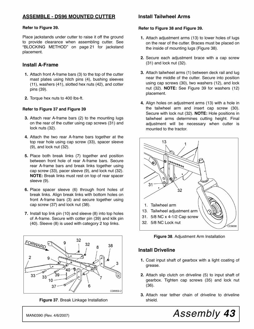
Assembly 43MAN0390 (Rev. 4/6/2007)
ASSEMBLE - DS96 MOUNTED CUTTER
Refer to Figure 39.
Place jackstands under cutter to raise it off the groundto provide clearance when assembling cutter. See“BLOCKING METHOD” on page 21 for jackstandplacement.
Install A-Frame
1. Attach front A-frame bars (3) to the top of the cuttermast plates using hitch pins (4), bushing sleeves(11), washers (41), slotted hex nuts (42), and cotterpins (39).
2. Torque hex nuts to 400 lbs-ft.
Refer to Figure 37 and Figure 39
3. Attach rear A-frame bars (2) to the mounting lugson the rear of the cutter using cap screws (31) andlock nuts (32).
4. Attach the two rear A-frame bars together at thetop rear hole using cap screw (33), spacer sleeve(9), and lock nut (32).
5. Place both break links (7) together and positionbetween front hole of rear A-frame bars. Securerear A-frame bars and break links together usingcap screw (33), pacer sleeve (9), and lock nut (32).NOTE: Break links must rest on top of rear spacersleeve (9).
6. Place spacer sleeve (6) through front holes ofbreak links. Align break links with bottom holes onfront A-frame bars (3) and secure together usingcap screw (37) and lock nut (38).
7. Install top link pin (10) and sleeve (8) into top holesof A-frame. Secure with cotter pin (39) and klik pin(40). Sleeve (8) is used with category 2 top links.
Figure 37. Break Linkage Installation
Install Tailwheel Arms
Refer to Figure 38 and Figure 39.
1. Attach adjustment arms (13) to lower holes of lugson the rear of the cutter. Braces must be placed onthe inside of mounting lugs (Figure 38).
2. Secure each adjustment brace with a cap screw(31) and lock nut (32).
3. Attach tailwheel arms (1) between deck rail and lugnear the middle of the cutter. Secure into positionusing cap screws (30), two washers (12), and locknut (32). NOTE: See Figure 39 for washers (12)placement.
4. Align holes on adjustment arms (13) with a hole inthe tailwheel arm and insert cap screw (30).Secure with lock nut (32). NOTE: Hole positions intailwheel arms determines cutting height. Finaladjustment will be necessary when cutter ismounted to the tractor.
Figure 38. Adjustment Arm Installation
Install Driveline
1. Coat input shaft of gearbox with a light coating ofgrease.
2. Attach slip clutch on driveline (5) to input shaft ofgearbox. Tighten cap screws (35) and lock nut(36).
3. Attach rear tether chain of driveline to drivelineshield.
1. Tailwheel arm13. Tailwheel adjustment arm31. 5/8 NC x 4-1/2 Cap screw32. 5/8 NC Lock nut
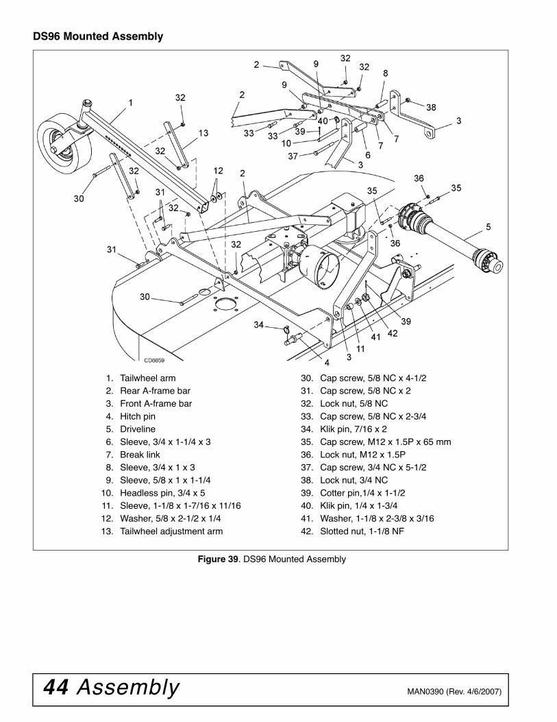
44 Assembly MAN0390 (Rev. 4/6/2007)
DS96 Mounted Assembly
Figure 39. DS96 Mounted Assembly
1. Tailwheel arm2. Rear A-frame bar3. Front A-frame bar4. Hitch pin5. Driveline6. Sleeve, 3/4 x 1-1/4 x 37. Break link8. Sleeve, 3/4 x 1 x 39. Sleeve, 5/8 x 1 x 1-1/4
10. Headless pin, 3/4 x 511. Sleeve, 1-1/8 x 1-7/16 x 11/1612. Washer, 5/8 x 2-1/2 x 1/413. Tailwheel adjustment arm
30. Cap screw, 5/8 NC x 4-1/231. Cap screw, 5/8 NC x 232. Lock nut, 5/8 NC 33. Cap screw, 5/8 NC x 2-3/434. Klik pin, 7/16 x 235. Cap screw, M12 x 1.5P x 65 mm36. Lock nut, M12 x 1.5P37. Cap screw, 3/4 NC x 5-1/238. Lock nut, 3/4 NC39. Cotter pin,1/4 x 1-1/240. Klik pin, 1/4 x 1-3/441. Washer, 1-1/8 x 2-3/8 x 3/1642. Slotted nut, 1-1/8 NF
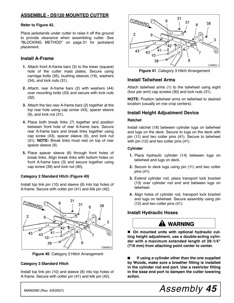
Assembly 45MAN0390 (Rev. 4/6/2007)
ASSEMBLE - DS120 MOUNTED CUTTER
Refer to Figure 42.
Place jackstands under cutter to raise it off the groundto provide clearance when assembling cutter. See“BLOCKING METHOD” on page 21 for jackstandplacement.
Install A-Frame
1. Attach front A-frame bars (3) to the lower (square)hole of the cutter mast plates. Secure usingcarriage bolts (35), bushing sleeves (19), washers(34), and lock nuts (31).
2. Attach, rear A-frame bars (2) with washers (44)over mounting bolts (33) and secure with lock nuts(32).
3. Attach the two rear A-frame bars (2) together at thetop rear hole using cap screw (43), spacer sleeve(9), and lock nut (31).
4. Place both break links (7) together and positionbetween front hole of rear A-frame bars. Securerear A-frame bars and break links together usingcap screw (43), spacer sleeve (9), and lock nut(31). NOTE: Break links must rest on top of rearspacer sleeve (9).
5. Place spacer sleeve (6) through front holes ofbreak links. Align break links with bottom holes onfront A-frame bars (3) and secure together usingcap screw (39) and lock nut (40).
Category 2 Standard Hitch (Figure 40)
Install top link pin (10) and sleeve (6) into top holes ofA-frame. Secure with cotter pin (41) and klik pin (42).
Figure 40. Category 2 Hitch Arrangement
Category 3 Standard Hitch
Install top link pin (10) and sleeve (8) into top holes ofA-frame. Secure with cotter pin (41) and klik pin (42).
Figure 41. Category 3 Hitch Arrangement
Install Tailwheel Arms
Attach tailwheel arms (1) to the tailwheel using eight(four per arm) cap screws (30) and lock nuts (31).
NOTE: Position tailwheel arms on tailwheel to desiredlocation (usually on row crop centers).
Install Height Adjustment Device
Ratchet
Install ratchet (18) between cylinder lugs on tailwheeland lugs on the deck. Secure to lugs on the deck withpin (11) and two cotter pins (41). Secure to tailwheelwith pin (12) and two cotter pins (41).
Cylinder
1. Place hydraulic cylinder (14) between lugs ontailwheel and lugs on deck.
2. Secure to deck lugs using pin (11) and two cotterpins (41).
3. Extend cylinder rod, place transport lock bracket(13) over cylinder rod end and between lugs ontailwheel.
4. Align holes of cylinder rod, transport lock bracketand lugs on tailwheel. Secure assembly using pin(12) and two cotter pins (41).
Install Hydraulic Hoses
On mounted units with optional hydraulic cut-ting height adjustment, use a double-acting cylin-der with a maximum extended length of 28-1/4"(718 mm) from attaching point center to center.
■ If using a cylinder other than the one suppliedby Woods, make sure a breather fitting is installedin the cylinder rod end port. Use a restricter fittingin the base end port to dampen the cutter loweringaction.
�������
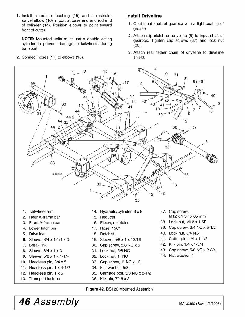
46 Assembly MAN0390 (Rev. 4/6/2007)
1. Install a reducer bushing (15) and a restricterswivel elbow (16) in port at base end and rod endof cylinder (14). Position elbows to point towardfront of cutter.
NOTE: Mounted units must use a double actingcylinder to prevent damage to tailwheels duringtransport.
2. Connect hoses (17) to elbows (16).
Install Driveline
1. Coat input shaft of gearbox with a light coating ofgrease.
2. Attach slip clutch on driveline (5) to input shaft ofgearbox. Tighten cap screws (37) and lock nut(38).
3. Attach rear tether chain of driveline to drivelineshield.
Figure 42. DS120 Mounted Assembly
1. Tailwheel arm2. Rear A-frame bar3. Front A-frame bar4. Lower hitch pin5. Driveline6. Sleeve, 3/4 x 1-1/4 x 37. Break link8. Sleeve, 3/4 x 1 x 39. Sleeve, 5/8 x 1 x 1-1/4
10. Headless pin, 3/4 x 511. Headless pin, 1 x 4-1/212. Headless pin, 1 x 513. Transport lock-up
37. Cap screw, M12 x 1.5P x 65 mm
38. Lock nut, M12 x 1.5P39. Cap screw, 3/4 NC x 5-1/240. Lock nut, 3/4 NC41. Cotter pin, 1/4 x 1-1/242. Klik pin, 1/4 x 1-3/443. Cap screw, 5/8 NC x 2-3/444. Flat washer, 1"
14. Hydraulic cylinder, 3 x 815. Reducer16. Elbow, restricter17. Hose, 156"18. Ratchet19. Sleeve, 5/8 x 1 x 13/1630. Cap screw, 5/8 NC x 531. Lock nut, 5/8 NC32. Lock nut, 1" NC33. Cap screw, 1" NC x 1234. Flat washer, 5/835. Carriage bolt, 5/8 NC x 2-1/236. Klik pin, 7/16 x 2
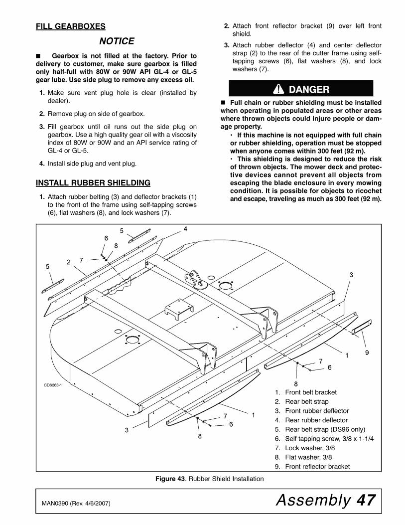
Assembly 47MAN0390 (Rev. 4/6/2007)
FILL GEARBOXES
NOTICE
■ Gearbox is not filled at the factory. Prior todelivery to customer, make sure gearbox is filledonly half-full with 80W or 90W API GL-4 or GL-5gear lube. Use side plug to remove any excess oil.
1. Make sure vent plug hole is clear (installed bydealer).
2. Remove plug on side of gearbox.
3. Fill gearbox until oil runs out the side plug ongearbox. Use a high quality gear oil with a viscosityindex of 80W or 90W and an API service rating ofGL-4 or GL-5.
4. Install side plug and vent plug.
INSTALL RUBBER SHIELDING
1. Attach rubber belting (3) and deflector brackets (1)to the front of the frame using self-tapping screws(6), flat washers (8), and lock washers (7).
2. Attach front reflector bracket (9) over left frontshield.
3. Attach rubber deflector (4) and center deflectorstrap (2) to the rear of the cutter frame using self-tapping screws (6), flat washers (8), and lockwashers (7).
Full chain or rubber shielding must be installedwhen operating in populated areas or other areaswhere thrown objects could injure people or dam-age property.
• If this machine is not equipped with full chainor rubber shielding, operation must be stoppedwhen anyone comes within 300 feet (92 m).• This shielding is designed to reduce the riskof thrown objects. The mower deck and protec-tive devices cannot prevent all objects fromescaping the blade enclosure in every mowingcondition. It is possible for objects to ricochetand escape, traveling as much as 300 feet (92 m).
Figure 43. Rubber Shield Installation
������
1. Front belt bracket2. Rear belt strap3. Front rubber deflector4. Rear rubber deflector5. Rear belt strap (DS96 only)6. Self tapping screw, 3/8 x 1-1/47. Lock washer, 3/88. Flat washer, 3/89. Front reflector bracket
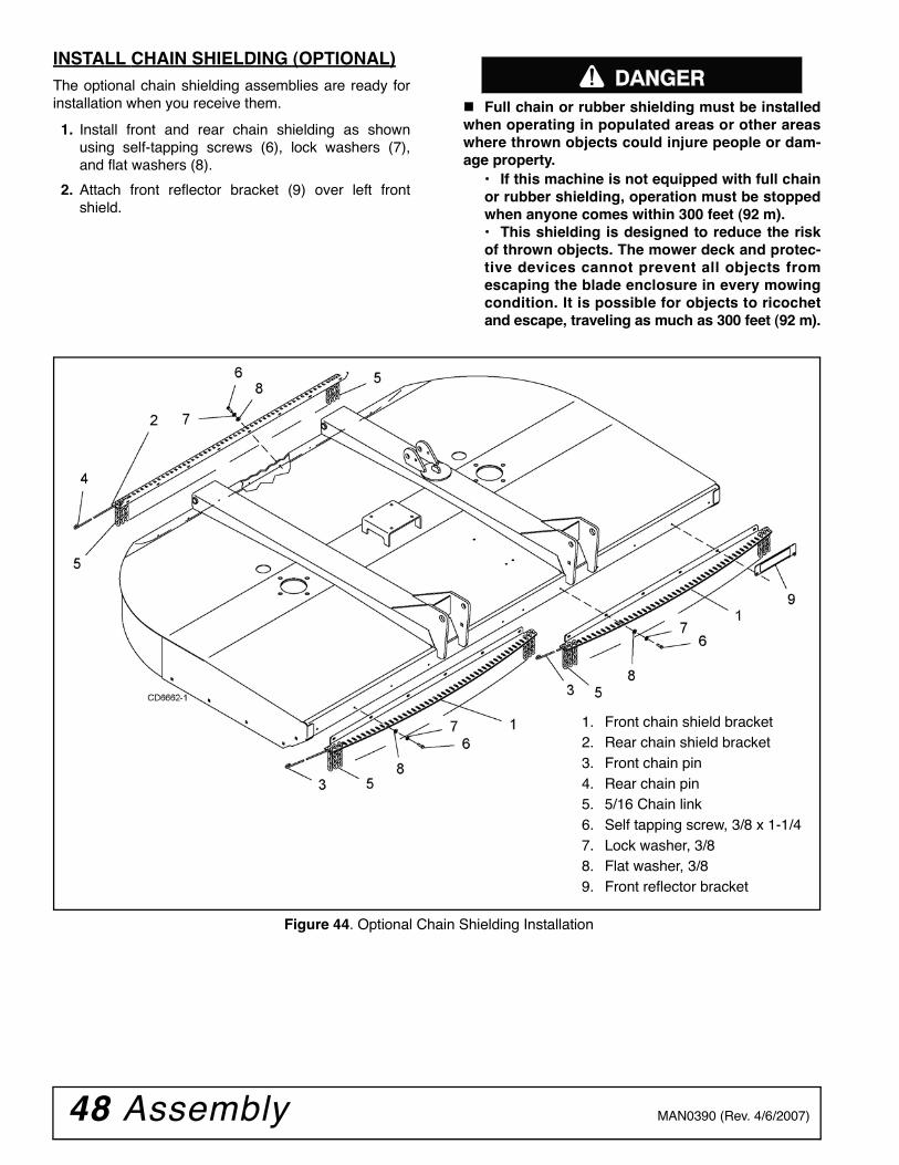
48 Assembly MAN0390 (Rev. 4/6/2007)
INSTALL CHAIN SHIELDING (OPTIONAL)The optional chain shielding assemblies are ready forinstallation when you receive them.
1. Install front and rear chain shielding as shownusing self-tapping screws (6), lock washers (7),and flat washers (8).
2. Attach front reflector bracket (9) over left frontshield.
Full chain or rubber shielding must be installedwhen operating in populated areas or other areaswhere thrown objects could injure people or dam-age property.
• If this machine is not equipped with full chainor rubber shielding, operation must be stoppedwhen anyone comes within 300 feet (92 m).• This shielding is designed to reduce the riskof thrown objects. The mower deck and protec-tive devices cannot prevent all objects fromescaping the blade enclosure in every mowingcondition. It is possible for objects to ricochetand escape, traveling as much as 300 feet (92 m).
Figure 44. Optional Chain Shielding Installation
������
1. Front chain shield bracket2. Rear chain shield bracket3. Front chain pin4. Rear chain pin5. 5/16 Chain link6. Self tapping screw, 3/8 x 1-1/47. Lock washer, 3/88. Flat washer, 3/89. Front reflector bracket
Dealer Check Lists 49MAN0390 (Rev. 4/6/2007)
DEALER CHECK LISTS
PRE-DELIVERY CHECK LIST(DEALER’S RESPONSIBILITY)Inspect cutter thoroughly after assembly to make sureit is set up properly before delivering it to the customer.The following check list is a reminder of points toinspect. Check off each item as it is found satisfactory,corrections are made, or services are performed.
NOTICE■ Gearbox was not filled at the factory. It must beserviced before operating cutter. (See LUBRICA-TION, page 21). Failure to service will result in dam-age to gearbox.
___ Check that gearbox is properly serviced andseals are not leaking.
___ Check and grease all lubrication points as identi-fied in Owner Service, LUBRICATION, page 21.
___ Check that blades have been properly installed.
___ Check all bolts to be sure they are properlytorqued.
___ Check that all cotter pins are properly installedand secured.
___ Check that PTO shaft is properly installed.
DELIVERY CHECK LIST(DEALER’S RESPONSIBILITY___ Show customer how to make adjustments.
Describe the options available for this cutter andexplain their purpose.
___ Explain importance of lubrication to customer andpoint out lubrication points on cutter.
___ Point out all guards and shielding. Explain theirimportance and the safety hazards that existwhen not kept in place and in good condition.
___ For mounted units, add wheel weights, ballast infront tires, and/or front tractor weight to enhancefront end stability. A minimum 20% of tractor andequipment gross weight must be on front tractorwheels. When adding weight to attain 20% oftractor and equipment weight on front tractorwheels, you must not exceed the ROPS weightcertification. Weigh the tractor and equipment. Donot estimate!
___ Present Operator's Manual and request that cus-tomer and all operators read it before operatingequipment. Point out the manual safety rules,explain their meanings and emphasize theincreased safety hazards that exist when safetyrules are not followed.
___ Explain to customer that when equipment istransported on a road or highway, safety devicesshould be used to give adequate warning to oper-ators of other vehicles.

50 Dealer Check Lists MAN0390 (Rev. 4/6/2007)
NOTES

Parts 51MAN0390 (Rev. 4/6/2007)
PARTS INDEX
Rotary CuttersDS96 & DS120MAIN FRAME ASSEMBLY. . . . . . . . . . . . . . . . . . . . . . . . . . . . . . . . . . . . . . . . . . . . 52
MAIN FRAME ASSEMBLY PARTS LIST . . . . . . . . . . . . . . . . . . . . . . . . . . . . . . . . . 53
ASSEMBLY, FRONT HALF . . . . . . . . . . . . . . . . . . . . . . . . . . . . . . . . . . . . . . . . . . . 54
PULL-TYPE ASSEMBLY, FRONT HALF PARTS LIST . . . . . . . . . . . . . . . . . . . . . . 55
PULL-TYPE ASSEMBLY, REAR HALFDS96 . . . . . . . . . . . . . . . . . . . . . . . . . . . . . . . . . . . . . . . . . . . . . . . . . . . . . . . . . . . 56DS120 . . . . . . . . . . . . . . . . . . . . . . . . . . . . . . . . . . . . . . . . . . . . . . . . . . . . . . . . . . 57
MOUNTED ASSEMBLYDS96 . . . . . . . . . . . . . . . . . . . . . . . . . . . . . . . . . . . . . . . . . . . . . . . . . . . . . . . . . . . 58DS120 . . . . . . . . . . . . . . . . . . . . . . . . . . . . . . . . . . . . . . . . . . . . . . . . . . . . . . . . . . 59
MOUNTED TAILWHEEL ASSEMBLY . . . . . . . . . . . . . . . . . . . . . . . . . . . . . . . . . . . 60
SPLITTER GEARBOX ASSEMBLY . . . . . . . . . . . . . . . . . . . . . . . . . . . . . . . . . . . . . 61
SPINDLE GEARBOX ASSEMBLY . . . . . . . . . . . . . . . . . . . . . . . . . . . . . . . . . . . . . . 62
SPINDLE GEARBOX ASSEMBLY PARTS LIST . . . . . . . . . . . . . . . . . . . . . . . . . . . 63
FLEXIBLE COUPLER . . . . . . . . . . . . . . . . . . . . . . . . . . . . . . . . . . . . . . . . . . . . . . . 63
PULL-TYPE DRIVELINE, REAR 1/3 . . . . . . . . . . . . . . . . . . . . . . . . . . . . . . . . . . . . 64
SLIP CLUTCH DRIVE ASSEMBLY . . . . . . . . . . . . . . . . . . . . . . . . . . . . . . . . . . . . . 65
3-JOINT DRIVE, FRONT 2/3 . . . . . . . . . . . . . . . . . . . . . . . . . . . . . . . . . . . . . . . . . . 66
4 BOLT WHEEL & TIRE ASSEMBLY. . . . . . . . . . . . . . . . . . . . . . . . . . . . . . . . . . . . 67
5 BOLT WHEEL & TIRE ASSEMBLY. . . . . . . . . . . . . . . . . . . . . . . . . . . . . . . . . . . . 68
BELT SHIELDING . . . . . . . . . . . . . . . . . . . . . . . . . . . . . . . . . . . . . . . . . . . . . . . . . . 69
CHAIN SHIELDING (OPTIONAL). . . . . . . . . . . . . . . . . . . . . . . . . . . . . . . . . . . . . . . 70
3 X 8 SINGLE-ACTING HYDRAULIC CYLINDER . . . . . . . . . . . . . . . . . . . . . . . . . . 71
HYDRAULIC CYLINDER STROKE CONTROL KIT - PULL-TYPE . . . . . . . . . . . . . 72
PARKING JACK - PULL-TYPE. . . . . . . . . . . . . . . . . . . . . . . . . . . . . . . . . . . . . . . . . 72
CROSSBAR PULLER (OPTIONAL) . . . . . . . . . . . . . . . . . . . . . . . . . . . . . . . . . . . . . 73
(Rev. 4/18/2012)
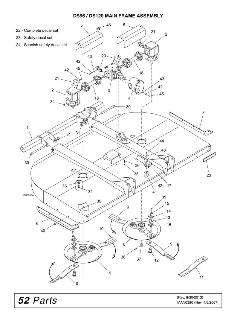
52 Parts MAN0390 (Rev. 4/6/2007)
DS96 / DS120 MAIN FRAME ASSEMBLY
22 - Complete decal set
23 - Safety decal set
24 - Spanish safety decal set
(Rev. 8/30/2013)
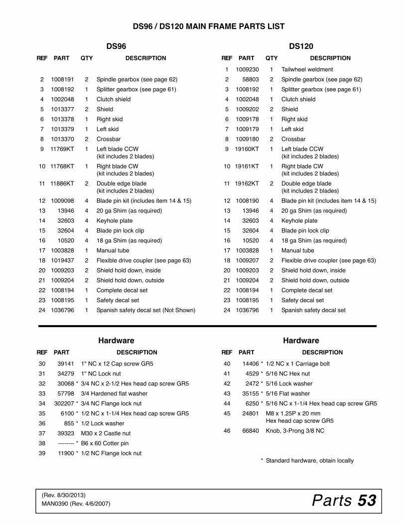
Parts 53MAN0390 (Rev. 4/6/2007)
DS96 / DS120 MAIN FRAME PARTS LIST
DS96 DS120
Hardware Hardware
REF PART QTY DESCRIPTION
2 1008191 2 Spindle gearbox (see page 62)
3 1008192 1 Splitter gearbox (see page 61)
4 1002048 1 Clutch shield
5 1013377 2 Shield
6 1013378 1 Right skid
7 1013379 1 Left skid
8 1013370 2 Crossbar
9 11769KT 1 Left blade CCW(kit includes 2 blades)
10 11768KT 1 Right blade CW(kit includes 2 blades)
11 11886KT 2 Double edge blade(kit includes 2 blades)
12 1009098 4 Blade pin kit (includes item 14 & 15)
13 13946 4 20 ga Shim (as required)
14 32603 4 Keyhole plate
15 32604 4 Blade pin lock clip
16 10520 4 18 ga Shim (as required)
17 1003828 1 Manual tube
18 1019437 2 Flexible drive coupler (see page 63)
20 1009203 2 Shield hold down, inside
21 1009204 2 Shield hold down, outside
22 1008194 1 Complete decal set
23 1008195 1 Safety decal set
24 1036796 1 Spanish safety decal set (Not Shown)
REF PART QTY DESCRIPTION
1 1009230 1 Tailwheel weldment
2 58803 2 Spindle gearbox (see page 62)
3 1008192 1 Splitter gearbox (see page 61)
4 1002048 1 Clutch shield
5 1009202 2 Shield
6 1009178 1 Right skid
7 1009179 1 Left skid
8 1009180 2 Crossbar
9 19160KT 1 Left blade CCW(kit includes 2 blades)
10 19161KT 1 Right blade CW(kit includes 2 blades)
11 19162KT 2 Double edge blade(kit includes 2 blades)
12 1008190 4 Blade pin kit (includes item 14 & 15)
13 13946 4 20 ga Shim (as required)
14 32603 4 Keyhole plate
15 32604 4 Blade pin lock clip
16 10520 4 18 ga Shim (as required)
17 1003828 1 Manual tube
18 1009207 2 Flexible drive coupler (see page 63)
20 1009203 2 Shield hold down, inside
21 1009204 2 Shield hold down, outside
22 1008194 1 Complete decal set
23 1008195 1 Safety decal set
24 1036796 1 Spanish safety decal set
REF PART DESCRIPTION
30 39141 1" NC x 12 Cap screw GR5
31 34279 1" NC Lock nut
32 30068 * 3/4 NC x 2-1/2 Hex head cap screw GR5
33 57798 3/4 Hardened flat washer
34 302207 * 3/4 NC Flange lock nut
35 6100 * 1/2 NC x 1-1/4 Hex head cap screw GR5
36 855 * 1/2 Lock washer
37 39323 M30 x 2 Castle nut
38 -------- * B6 x 60 Cotter pin
39 11900 * 1/2 NC Flange lock nut
REF PART DESCRIPTION
40 14406 * 1/2 NC x 1 Carriage bolt
41 4529 * 5/16 NC Hex nut
42 2472 * 5/16 Lock washer
43 35155 * 5/16 Flat washer
44 6250 * 5/16 NC x 1-1/4 Hex head cap screw GR5
45 24801 M8 x 1.25P x 20 mmHex head cap screw GR5
46 66840 Knob, 3-Prong 3/8 NC
* Standard hardware, obtain locally
(Rev. 8/30/2013)
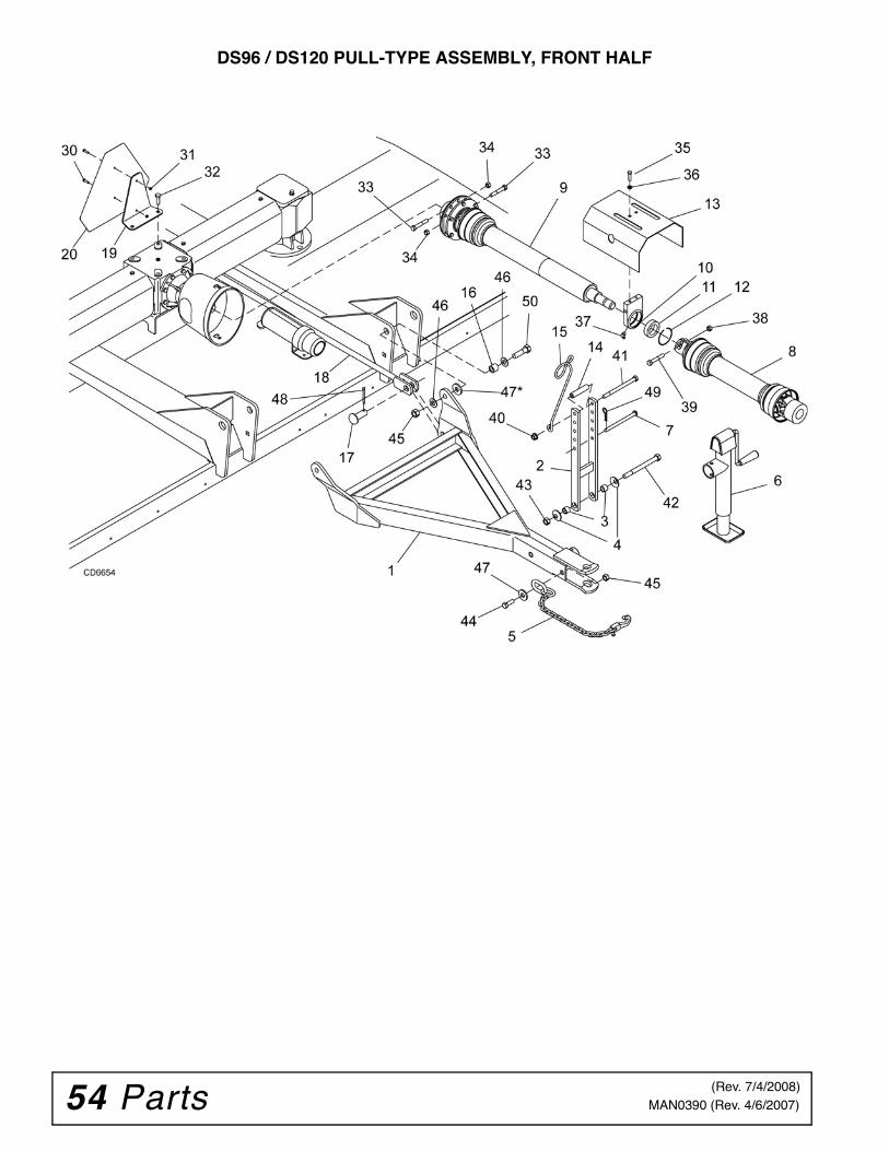
54 Parts MAN0390 (Rev. 4/6/2007)
DS96 / DS120 PULL-TYPE ASSEMBLY, FRONT HALF
(Rev. 7/4/2008)
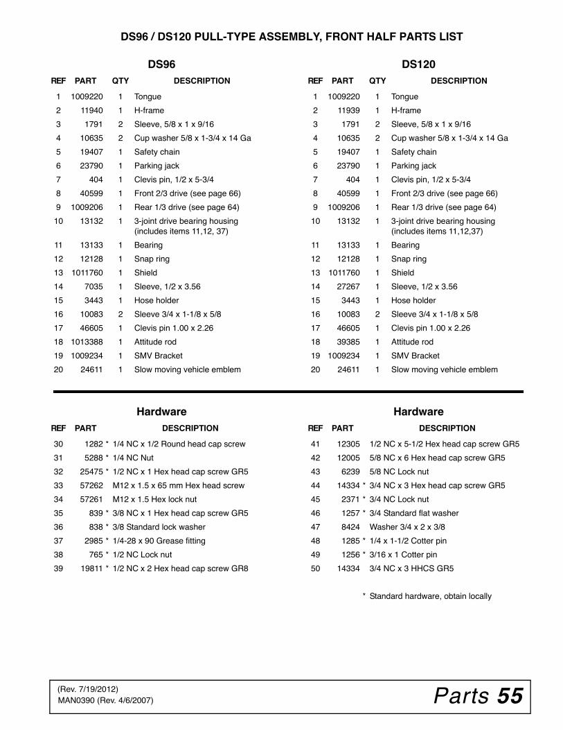
Parts 55MAN0390 (Rev. 4/6/2007)
DS96 / DS120 PULL-TYPE ASSEMBLY, FRONT HALF PARTS LIST
DS96 DS120
Hardware Hardware
REF PART QTY DESCRIPTION
1 1009220 1 Tongue
2 11940 1 H-frame
3 1791 2 Sleeve, 5/8 x 1 x 9/16
4 10635 2 Cup washer 5/8 x 1-3/4 x 14 Ga
5 19407 1 Safety chain
6 23790 1 Parking jack
7 404 1 Clevis pin, 1/2 x 5-3/4
8 40599 1 Front 2/3 drive (see page 66)
9 1009206 1 Rear 1/3 drive (see page 64)
10 13132 1 3-joint drive bearing housing (includes items 11,12, 37)
11 13133 1 Bearing
12 12128 1 Snap ring
13 1011760 1 Shield
14 7035 1 Sleeve, 1/2 x 3.56
15 3443 1 Hose holder
16 10083 2 Sleeve 3/4 x 1-1/8 x 5/8
17 46605 1 Clevis pin 1.00 x 2.26
18 1013388 1 Attitude rod
19 1009234 1 SMV Bracket
20 24611 1 Slow moving vehicle emblem
REF PART QTY DESCRIPTION
1 1009220 1 Tongue
2 11939 1 H-frame
3 1791 2 Sleeve, 5/8 x 1 x 9/16
4 10635 2 Cup washer 5/8 x 1-3/4 x 14 Ga
5 19407 1 Safety chain
6 23790 1 Parking jack
7 404 1 Clevis pin, 1/2 x 5-3/4
8 40599 1 Front 2/3 drive (see page 66)
9 1009206 1 Rear 1/3 drive (see page 64)
10 13132 1 3-joint drive bearing housing (includes items 11,12,37)
11 13133 1 Bearing
12 12128 1 Snap ring
13 1011760 1 Shield
14 27267 1 Sleeve, 1/2 x 3.56
15 3443 1 Hose holder
16 10083 2 Sleeve 3/4 x 1-1/8 x 5/8
17 46605 1 Clevis pin 1.00 x 2.26
18 39385 1 Attitude rod
19 1009234 1 SMV Bracket
20 24611 1 Slow moving vehicle emblem
REF PART DESCRIPTION
30 1282 * 1/4 NC x 1/2 Round head cap screw
31 5288 * 1/4 NC Nut
32 25475 * 1/2 NC x 1 Hex head cap screw GR5
33 57262 M12 x 1.5 x 65 mm Hex head screw
34 57261 M12 x 1.5 Hex lock nut
35 839 * 3/8 NC x 1 Hex head cap screw GR5
36 838 * 3/8 Standard lock washer
37 2985 * 1/4-28 x 90 Grease fitting
38 765 * 1/2 NC Lock nut
39 19811 * 1/2 NC x 2 Hex head cap screw GR8
REF PART DESCRIPTION
41 12305 1/2 NC x 5-1/2 Hex head cap screw GR5
42 12005 5/8 NC x 6 Hex head cap screw GR5
43 6239 5/8 NC Lock nut
44 14334 * 3/4 NC x 3 Hex head cap screw GR5
45 2371 * 3/4 NC Lock nut
46 1257 * 3/4 Standard flat washer
47 8424 Washer 3/4 x 2 x 3/8
48 1285 * 1/4 x 1-1/2 Cotter pin
49 1256 * 3/16 x 1 Cotter pin
50 14334 3/4 NC x 3 HHCS GR5
* Standard hardware, obtain locally
(Rev. 7/19/2012)
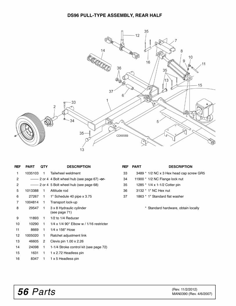
56 Parts MAN0390 (Rev. 4/6/2007)
DS96 PULL-TYPE ASSEMBLY, REAR HALF
REF PART QTY DESCRIPTION
1 1035103 1 Tailwheel weldment
2 ------- 2 or 4 4 Bolt wheel hub (see page 67) -or-
2 ------- 2 or 4 5 Bolt wheel hub (see page 68)
5 1013388 1 Attitude rod
6 27267 1 1" Schedule 40 pipe x 3.75
7 1004814 1 Transport lock-up
8 29547 1 3 x 8 Hydraulic cylinder(see page 71)
9 11893 1 1/2 to 1/4 Reducer
10 10290 1 1/4 x 1/4 90° Elbow w / 1/16 restricter
11 8669 1 1/4 x 156" Hose
12 1005020 1 Ratchet adjustment link
13 46605 2 Clevis pin 1.00 x 2.26
14 24098 1 1-1/4 Stroke control kit (see page 72)
15 1631 1 1 x 2.72 Headless pin
16 8347 1 1 x 5 Headless pin
REF PART DESCRIPTION
33 3489 * 1/2 NC x 3 Hex head cap screw GR5
34 11900 * 1/2 NC Flange lock nut
35 1285 * 1/4 x 1-1/2 Cotter pin
36 3132 * 1" NC Hex nut
37 1863 * 1" Standard flat washer
* Standard hardware, obtain locally
(Rev. 11/2/2012)
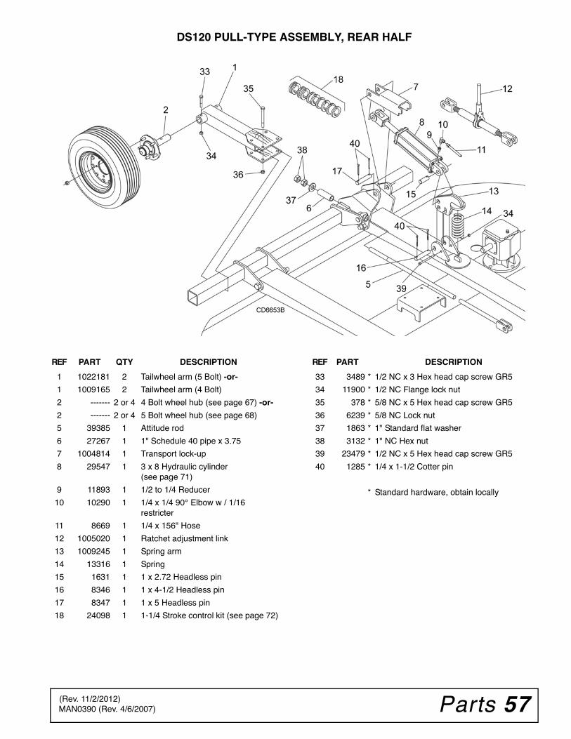
Parts 57MAN0390 (Rev. 4/6/2007)
DS120 PULL-TYPE ASSEMBLY, REAR HALF
REF PART QTY DESCRIPTION
1 1022181 2 Tailwheel arm (5 Bolt) -or-
1 1009165 2 Tailwheel arm (4 Bolt)
2 ------- 2 or 4 4 Bolt wheel hub (see page 67) -or-
2 ------- 2 or 4 5 Bolt wheel hub (see page 68)
5 39385 1 Attitude rod
6 27267 1 1" Schedule 40 pipe x 3.75
7 1004814 1 Transport lock-up
8 29547 1 3 x 8 Hydraulic cylinder(see page 71)
9 11893 1 1/2 to 1/4 Reducer
10 10290 1 1/4 x 1/4 90° Elbow w / 1/16 restricter
11 8669 1 1/4 x 156" Hose
12 1005020 1 Ratchet adjustment link
13 1009245 1 Spring arm
14 13316 1 Spring
15 1631 1 1 x 2.72 Headless pin
16 8346 1 1 x 4-1/2 Headless pin
17 8347 1 1 x 5 Headless pin
18 24098 1 1-1/4 Stroke control kit (see page 72)
REF PART DESCRIPTION
33 3489 * 1/2 NC x 3 Hex head cap screw GR5
34 11900 * 1/2 NC Flange lock nut
35 378 * 5/8 NC x 5 Hex head cap screw GR5
36 6239 * 5/8 NC Lock nut
37 1863 * 1" Standard flat washer
38 3132 * 1" NC Hex nut
39 23479 * 1/2 NC x 5 Hex head cap screw GR5
40 1285 * 1/4 x 1-1/2 Cotter pin
* Standard hardware, obtain locally
(Rev. 11/2/2012)
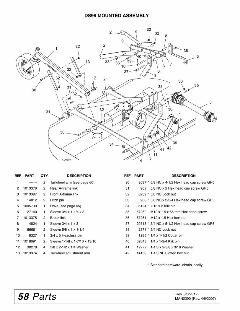
58 Parts MAN0390 (Rev. 4/6/2007)
DS96 MOUNTED ASSEMBLY
REF PART QTY DESCRIPTION
1 ------- 2 Tailwheel arm (see page 60)
2 1013376 2 Rear A-frame link
3 1013397 2 Front A-frame link
4 14012 2 Hitch pin
5 1005790 1 Drive (see page 65)
6 27140 1 Sleeve 3/4 x 1-1/4 x 3
7 1013375 2 Break link
8 14824 1 Sleeve 3/4 x 1 x 3
9 66661 2 Sleeve 5/8 x 1 x 1-1/4
10 8327 1 3/4 x 5 Headless pin
11 1018091 2 Sleeve 1-1/8 x 1-7/16 x 13/16
12 30278 4 5/8 x 2-1/2 x 1/4 Washer
13 1013374 4 Tailwheel adjustment arm
REF PART DESCRIPTION
30 3097 * 5/8 NC x 4-1/2 Hex head cap screw GR5
31 902 5/8 NC x 2 Hex head cap screw GR5
32 6239 * 5/8 NC Lock nut
33 986 * 5/8 NC x 2-3/4 Hex head cap screw GR5
34 35124 * 7/16 x 2 Klik pin
35 57262 M12 x 1.5 x 65 mm Hex head screw
36 57261 M12 x 1.5 Hex lock nut
37 29315 * 3/4 NC x 5-1/2 Hex head cap screw GR5
38 2371 * 3/4 NC Lock nut
39 1285 * 1/4 x 1-1/2 Cotter pin
40 62043 1/4 x 1-3/4 Klik pin
41 12272 1-1/8 x 2-3/8 x 3/16 Washer
42 14153 1-1/8 NF Slotted hex nut
* Standard hardware, obtain locally
(Rev. 8/6/2012)
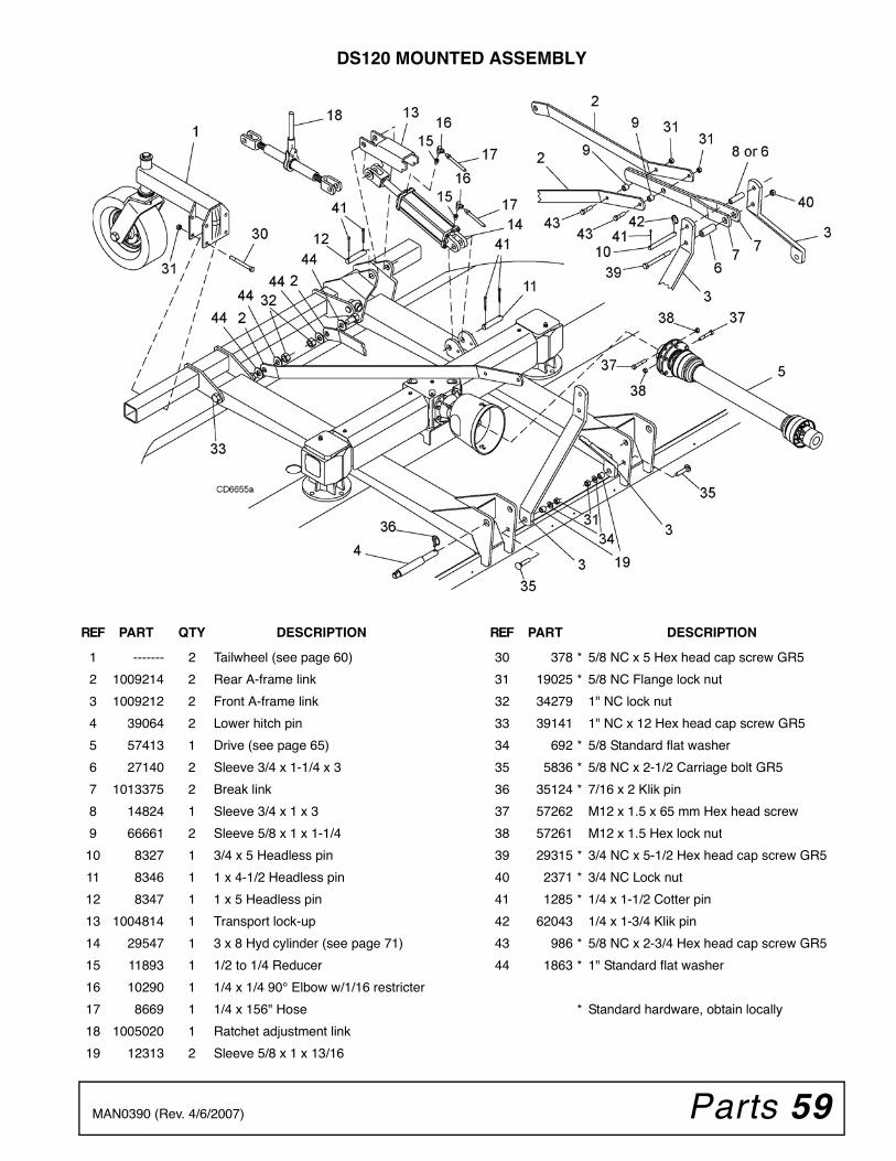
Parts 59MAN0390 (Rev. 4/6/2007)
DS120 MOUNTED ASSEMBLY
REF PART QTY DESCRIPTION
1 ------- 2 Tailwheel (see page 60)
2 1009214 2 Rear A-frame link
3 1009212 2 Front A-frame link
4 39064 2 Lower hitch pin
5 57413 1 Drive (see page 65)
6 27140 2 Sleeve 3/4 x 1-1/4 x 3
7 1013375 2 Break link
8 14824 1 Sleeve 3/4 x 1 x 3
9 66661 2 Sleeve 5/8 x 1 x 1-1/4
10 8327 1 3/4 x 5 Headless pin
11 8346 1 1 x 4-1/2 Headless pin
12 8347 1 1 x 5 Headless pin
13 1004814 1 Transport lock-up
14 29547 1 3 x 8 Hyd cylinder (see page 71)
15 11893 1 1/2 to 1/4 Reducer
16 10290 1 1/4 x 1/4 90° Elbow w/1/16 restricter
17 8669 1 1/4 x 156" Hose
18 1005020 1 Ratchet adjustment link
19 12313 2 Sleeve 5/8 x 1 x 13/16
REF PART DESCRIPTION
30 378 * 5/8 NC x 5 Hex head cap screw GR5
31 19025 * 5/8 NC Flange lock nut
32 34279 1" NC lock nut
33 39141 1" NC x 12 Hex head cap screw GR5
34 692 * 5/8 Standard flat washer
35 5836 * 5/8 NC x 2-1/2 Carriage bolt GR5
36 35124 * 7/16 x 2 Klik pin
37 57262 M12 x 1.5 x 65 mm Hex head screw
38 57261 M12 x 1.5 Hex lock nut
39 29315 * 3/4 NC x 5-1/2 Hex head cap screw GR5
40 2371 * 3/4 NC Lock nut
41 1285 * 1/4 x 1-1/2 Cotter pin
42 62043 1/4 x 1-3/4 Klik pin
43 986 * 5/8 NC x 2-3/4 Hex head cap screw GR5
44 1863 * 1" Standard flat washer
* Standard hardware, obtain locally
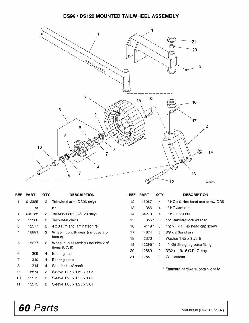
60 Parts MAN0390 (Rev. 4/6/2007)
DS96 / DS120 MOUNTED TAILWHEEL ASSEMBLY
REF PART QTY DESCRIPTION
1 1013385 2 Tail wheel arm (DS96 only)
or or
1 1009185 2 Tailwheel arm (DS120 only)
2 15580 2 Tail wheel clevis
3 12577 2 4 x 8 Rim and laminated tire
4 15591 2 Wheel hub with cups (includes 2 of item 6)
5 15277 2 Wheel hub assembly (includes 2 of items 6, 7, 8)
6 309 4 Bearing cup
7 310 4 Bearing cone
8 314 4 Seal for 1-1/2 shaft
9 15574 2 Sleeve 1.25 x 1.50 x .903
10 15575 2 Sleeve 1.25 x 1.50 x 1.86
11 15573 2 Sleeve 1.00 x 1.25 x 5.81
REF PART QTY DESCRIPTION
12 15087 4 1" NC x 9 Hex head cap screw GR5
13 1386 4 1" NC Jam nut
14 34279 4 1" NC Lock nut
15 855 * 8 1/2 Standard lock washer
16 4119 * 8 1/2 NF x 1 Hex head cap screw
17 4674 2 3/8 x 2 Spirol pin
18 2370 4 Washer 1.62 x 3 x .18
19 12296 * 2 1/4-28 Straight grease fitting
20 12889 2 3/32 x 1-9/16 O.D. O-ring
21 12881 2 Cap washer
* Standard hardware, obtain locally
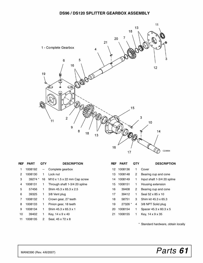
Parts 61MAN0390 (Rev. 4/6/2007)
DS96 / DS120 SPLITTER GEARBOX ASSEMBLY
REF PART QTY DESCRIPTION
1 1008192 -- Complete gearbox
2 1008130 1 Lock nut
3 39274 * 16 M10 x 1.5 x 22 mm Cap screw
4 1008131 1 Through shaft 1-3/4 20 spline
5 57456 1 Shim 45.3 x 65.3 x 2.5
6 39325 1 3/8 Vent plug
7 1008132 1 Crown gear, 27 teeth
8 1008133 1 Pinion gear, 18 teeth
9 1008134 1 Shim 45.3 x 65.3 x 1
10 39402 1 Key, 14 x 9 x 40
11 1008135 2 Seal, 45 x 72 x 8
REF PART QTY DESCRIPTION
12 1008136 1 Cover
13 1008148 2 Bearing cup and cone
14 1008149 1 Input shaft 1-3/4 20 spline
15 1008151 1 Housing extension
16 39408 2 Bearing cup and cone
17 39412 1 Seal 52 x 85 x 10
18 58751 3 Shim kit 45.3 x 65.3
19 27326 * 4 3/8 NPT Solid plug
20 1008154 1 Spacer 45.3 x 60.3 x 5
21 1008155 1 Key, 14 x 9 x 35
* Standard hardware, obtain locally
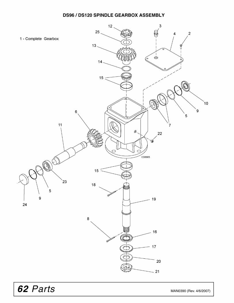
62 Parts MAN0390 (Rev. 4/6/2007)
DS96 / DS120 SPINDLE GEARBOX ASSEMBLY
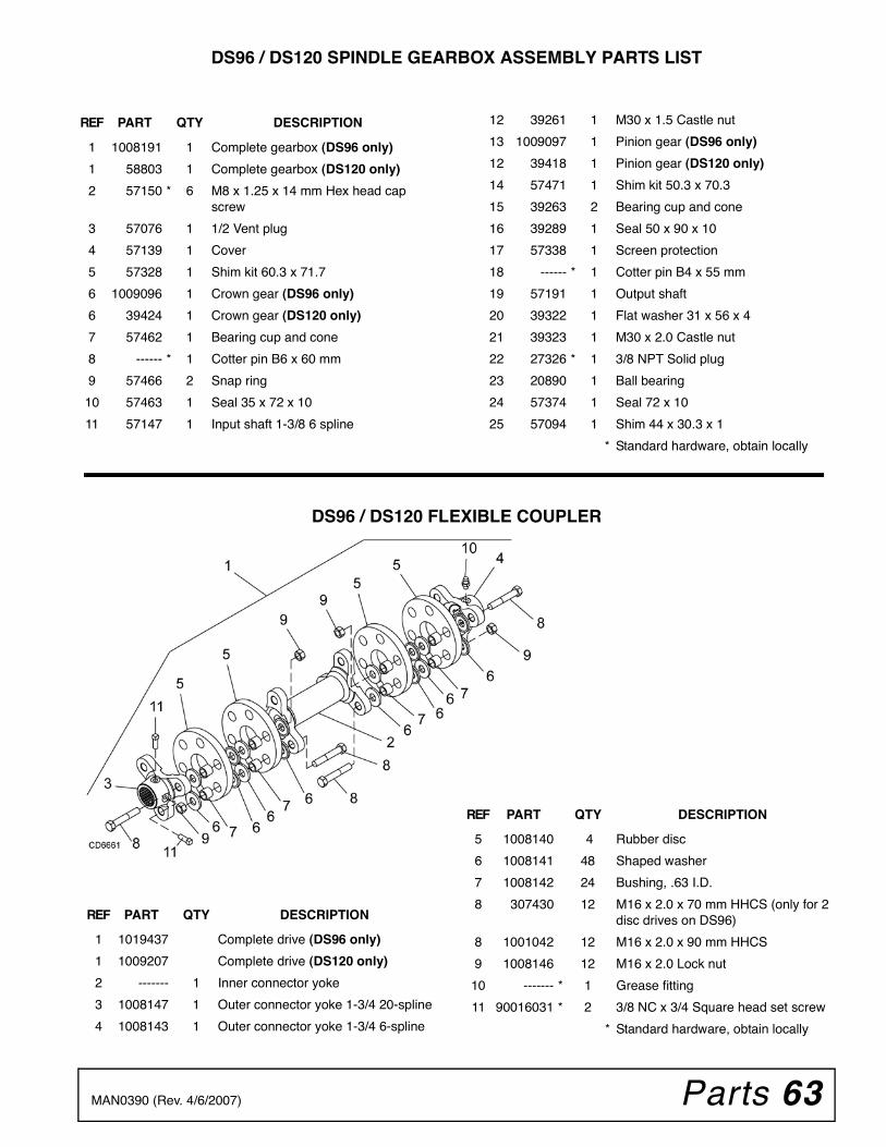
Parts 63MAN0390 (Rev. 4/6/2007)
DS96 / DS120 SPINDLE GEARBOX ASSEMBLY PARTS LIST
DS96 / DS120 FLEXIBLE COUPLER
REF PART QTY DESCRIPTION
1 1008191 1 Complete gearbox (DS96 only)
1 58803 1 Complete gearbox (DS120 only)
2 57150 * 6 M8 x 1.25 x 14 mm Hex head cap screw
3 57076 1 1/2 Vent plug
4 57139 1 Cover
5 57328 1 Shim kit 60.3 x 71.7
6 1009096 1 Crown gear (DS96 only)
6 39424 1 Crown gear (DS120 only)
7 57462 1 Bearing cup and cone
8 ------ * 1 Cotter pin B6 x 60 mm
9 57466 2 Snap ring
10 57463 1 Seal 35 x 72 x 10
11 57147 1 Input shaft 1-3/8 6 spline
12 39261 1 M30 x 1.5 Castle nut
13 1009097 1 Pinion gear (DS96 only)
12 39418 1 Pinion gear (DS120 only)
14 57471 1 Shim kit 50.3 x 70.3
15 39263 2 Bearing cup and cone
16 39289 1 Seal 50 x 90 x 10
17 57338 1 Screen protection
18 ------ * 1 Cotter pin B4 x 55 mm
19 57191 1 Output shaft
20 39322 1 Flat washer 31 x 56 x 4
21 39323 1 M30 x 2.0 Castle nut
22 27326 * 1 3/8 NPT Solid plug
23 20890 1 Ball bearing
24 57374 1 Seal 72 x 10
25 57094 1 Shim 44 x 30.3 x 1
* Standard hardware, obtain locally
REF PART QTY DESCRIPTION
5 1008140 4 Rubber disc
6 1008141 48 Shaped washer
7 1008142 24 Bushing, .63 I.D.
8 307430 12 M16 x 2.0 x 70 mm HHCS (only for 2 disc drives on DS96)
8 1001042 12 M16 x 2.0 x 90 mm HHCS
9 1008146 12 M16 x 2.0 Lock nut
10 ------- * 1 Grease fitting
11 90016031 * 2 3/8 NC x 3/4 Square head set screw
* Standard hardware, obtain locally
REF PART QTY DESCRIPTION
1 1019437 Complete drive (DS96 only)
1 1009207 Complete drive (DS120 only)
2 ------- 1 Inner connector yoke
3 1008147 1 Outer connector yoke 1-3/4 20-spline
4 1008143 1 Outer connector yoke 1-3/4 6-spline
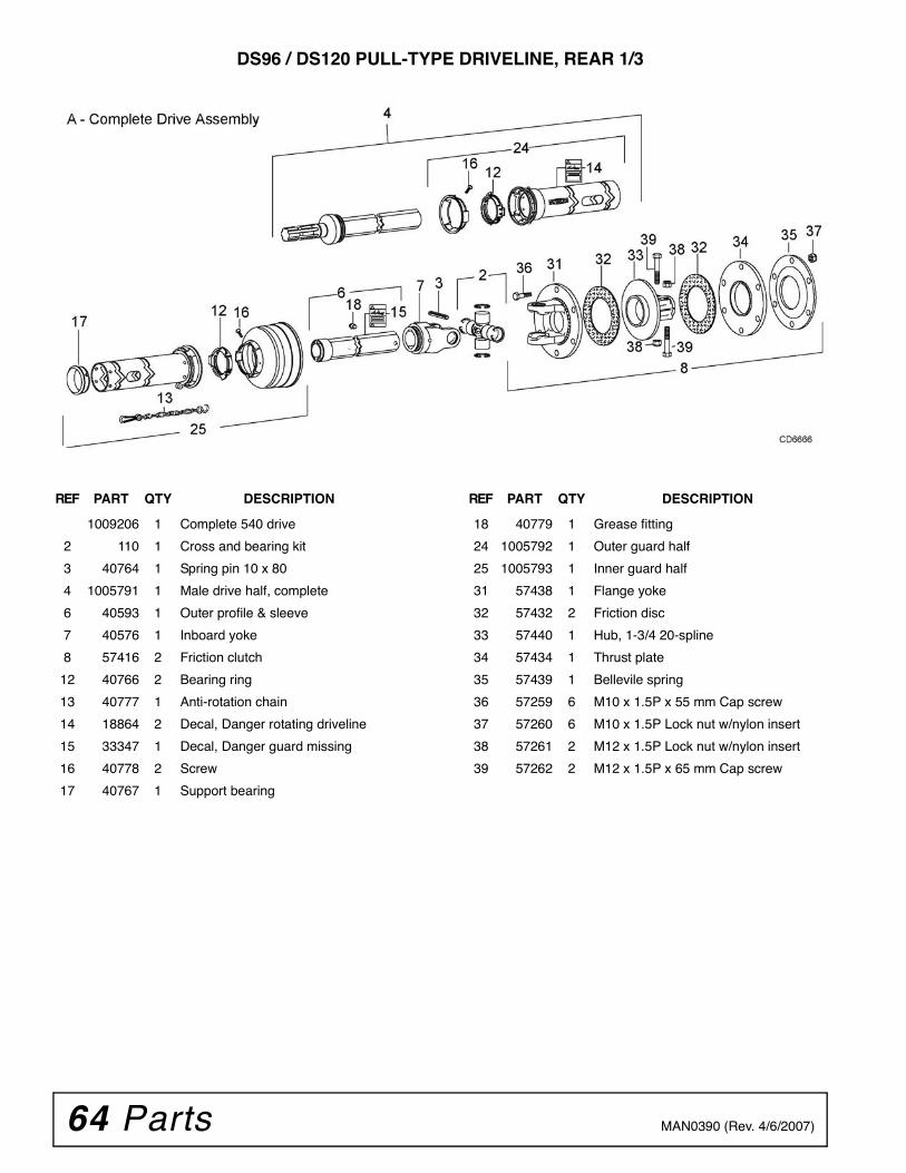
64 Parts MAN0390 (Rev. 4/6/2007)
DS96 / DS120 PULL-TYPE DRIVELINE, REAR 1/3
REF PART QTY DESCRIPTION
1009206 1 Complete 540 drive
2 110 1 Cross and bearing kit
3 40764 1 Spring pin 10 x 80
4 1005791 1 Male drive half, complete
6 40593 1 Outer profile & sleeve
7 40576 1 Inboard yoke
8 57416 2 Friction clutch
12 40766 2 Bearing ring
13 40777 1 Anti-rotation chain
14 18864 2 Decal, Danger rotating driveline
15 33347 1 Decal, Danger guard missing
16 40778 2 Screw
17 40767 1 Support bearing
REF PART QTY DESCRIPTION
18 40779 1 Grease fitting
24 1005792 1 Outer guard half
25 1005793 1 Inner guard half
31 57438 1 Flange yoke
32 57432 2 Friction disc
33 57440 1 Hub, 1-3/4 20-spline
34 57434 1 Thrust plate
35 57439 1 Bellevile spring
36 57259 6 M10 x 1.5P x 55 mm Cap screw
37 57260 6 M10 x 1.5P Lock nut w/nylon insert
38 57261 2 M12 x 1.5P Lock nut w/nylon insert
39 57262 2 M12 x 1.5P x 65 mm Cap screw
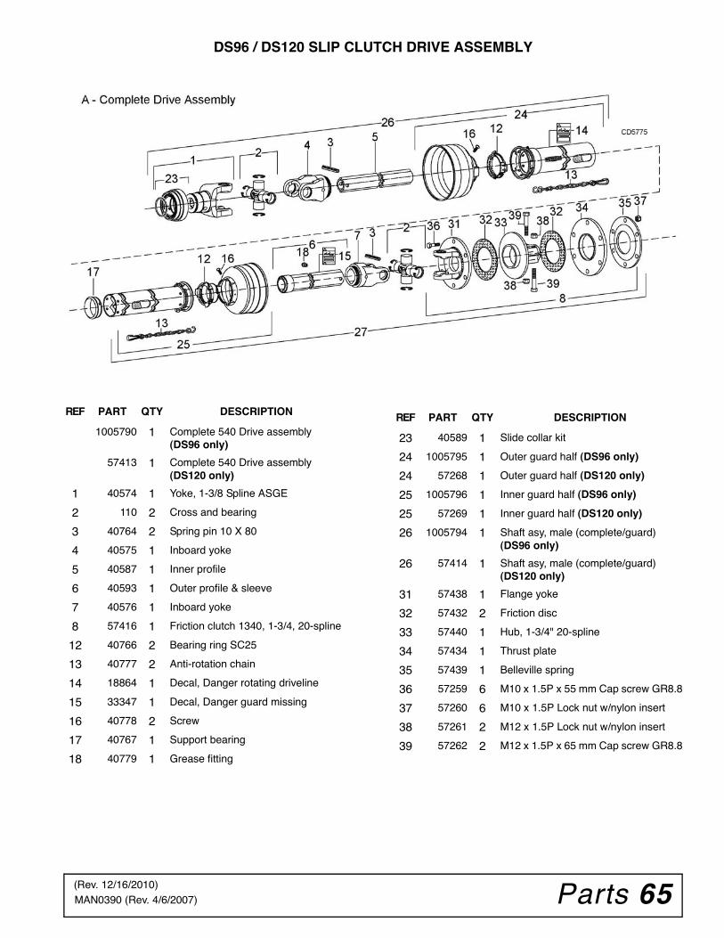
Parts 65MAN0390 (Rev. 4/6/2007)
DS96 / DS120 SLIP CLUTCH DRIVE ASSEMBLY
REF PART QTY DESCRIPTION
1005790 1 Complete 540 Drive assembly(DS96 only)
57413 1 Complete 540 Drive assembly(DS120 only)
1 40574 1 Yoke, 1-3/8 Spline ASGE
2 110 2 Cross and bearing
3 40764 2 Spring pin 10 X 80
4 40575 1 Inboard yoke
5 40587 1 Inner profile
6 40593 1 Outer profile & sleeve
7 40576 1 Inboard yoke
8 57416 1 Friction clutch 1340, 1-3/4, 20-spline
12 40766 2 Bearing ring SC25
13 40777 2 Anti-rotation chain
14 18864 1 Decal, Danger rotating driveline
15 33347 1 Decal, Danger guard missing
16 40778 2 Screw
17 40767 1 Support bearing
18 40779 1 Grease fitting
REF PART QTY DESCRIPTION
23 40589 1 Slide collar kit
24 1005795 1 Outer guard half (DS96 only)
24 57268 1 Outer guard half (DS120 only)
25 1005796 1 Inner guard half (DS96 only)
25 57269 1 Inner guard half (DS120 only)
26 1005794 1 Shaft asy, male (complete/guard) (DS96 only)
26 57414 1 Shaft asy, male (complete/guard) (DS120 only)
31 57438 1 Flange yoke
32 57432 2 Friction disc
33 57440 1 Hub, 1-3/4" 20-spline
34 57434 1 Thrust plate
35 57439 1 Belleville spring
36 57259 6 M10 x 1.5P x 55 mm Cap screw GR8.8
37 57260 6 M10 x 1.5P Lock nut w/nylon insert
38 57261 2 M12 x 1.5P Lock nut w/nylon insert
39 57262 2 M12 x 1.5P x 65 mm Cap screw GR8.8
(Rev. 12/16/2010)
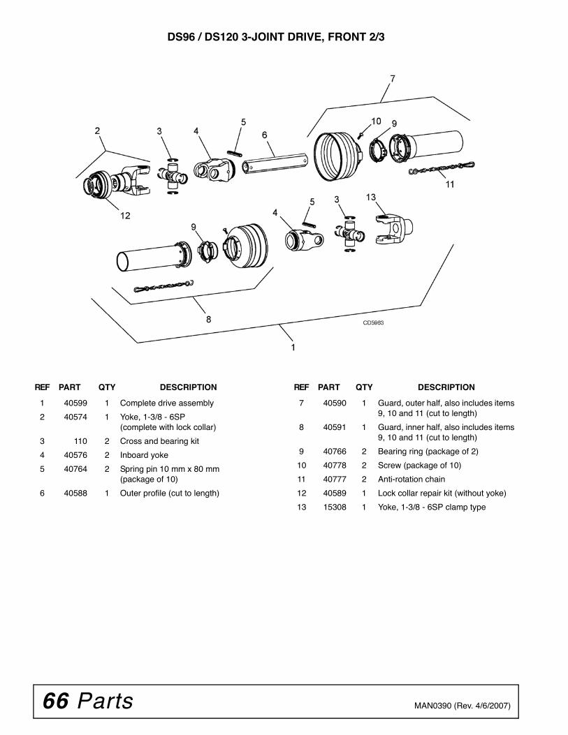
66 Parts MAN0390 (Rev. 4/6/2007)
DS96 / DS120 3-JOINT DRIVE, FRONT 2/3
REF PART QTY DESCRIPTION
1 40599 1 Complete drive assembly
2 40574 1 Yoke, 1-3/8 - 6SP(complete with lock collar)
3 110 2 Cross and bearing kit
4 40576 2 Inboard yoke
5 40764 2 Spring pin 10 mm x 80 mm(package of 10)
6 40588 1 Outer profile (cut to length)
REF PART QTY DESCRIPTION
7 40590 1 Guard, outer half, also includes items 9, 10 and 11 (cut to length)
8 40591 1 Guard, inner half, also includes items 9, 10 and 11 (cut to length)
9 40766 2 Bearing ring (package of 2)
10 40778 2 Screw (package of 10)
11 40777 2 Anti-rotation chain
12 40589 1 Lock collar repair kit (without yoke)
13 15308 1 Yoke, 1-3/8 - 6SP clamp type
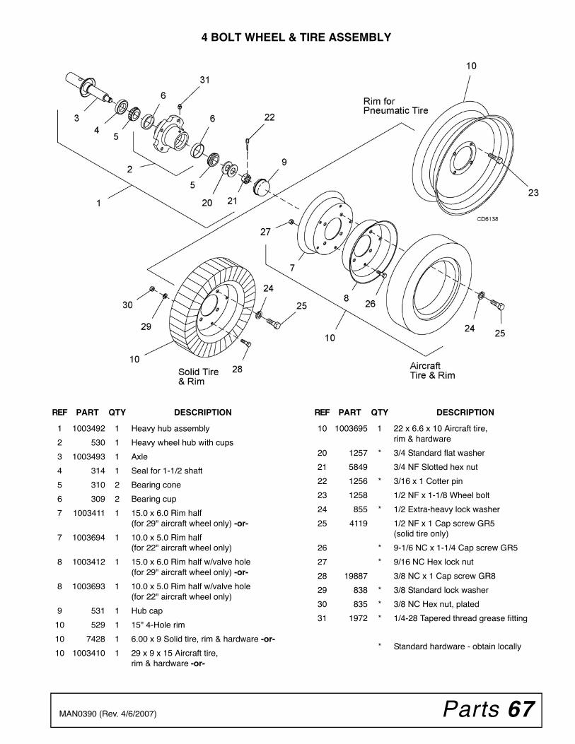
Parts 67MAN0390 (Rev. 4/6/2007)
4 BOLT WHEEL & TIRE ASSEMBLY
REF PART QTY DESCRIPTION
1 1003492 1 Heavy hub assembly
2 530 1 Heavy wheel hub with cups
3 1003493 1 Axle
4 314 1 Seal for 1-1/2 shaft
5 310 2 Bearing cone
6 309 2 Bearing cup
7 1003411 1 15.0 x 6.0 Rim half(for 29" aircraft wheel only) -or-
7 1003694 1 10.0 x 5.0 Rim half(for 22" aircraft wheel only)
8 1003412 1 15.0 x 6.0 Rim half w/valve hole(for 29" aircraft wheel only) -or-
8 1003693 1 10.0 x 5.0 Rim half w/valve hole(for 22" aircraft wheel only)
9 531 1 Hub cap
10 529 1 15" 4-Hole rim
10 7428 1 6.00 x 9 Solid tire, rim & hardware -or-
10 1003410 1 29 x 9 x 15 Aircraft tire,rim & hardware -or-
REF PART QTY DESCRIPTION
10 1003695 1 22 x 6.6 x 10 Aircraft tire,rim & hardware
20 1257 * 3/4 Standard flat washer
21 5849 3/4 NF Slotted hex nut
22 1256 * 3/16 x 1 Cotter pin
23 1258 1/2 NF x 1-1/8 Wheel bolt
24 855 * 1/2 Extra-heavy lock washer
25 4119 1/2 NF x 1 Cap screw GR5(solid tire only)
26 * 9-1/6 NC x 1-1/4 Cap screw GR5
27 * 9/16 NC Hex lock nut
28 19887 3/8 NC x 1 Cap screw GR8
29 838 * 3/8 Standard lock washer
30 835 * 3/8 NC Hex nut, plated
31 1972 * 1/4-28 Tapered thread grease fitting
* Standard hardware - obtain locally
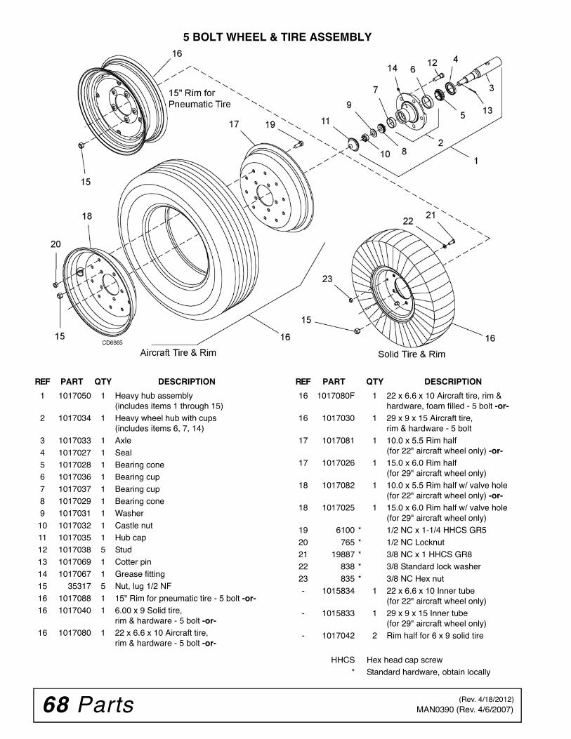
68 Parts MAN0390 (Rev. 4/6/2007)
5 BOLT WHEEL & TIRE ASSEMBLY
REF PART QTY DESCRIPTION
1 1017050 1 Heavy hub assembly(includes items 1 through 15)
2 1017034 1 Heavy wheel hub with cups(includes items 6, 7, 14)
3 1017033 1 Axle
4 1017027 1 Seal5 1017028 1 Bearing cone6 1017036 1 Bearing cup
7 1017037 1 Bearing cup8 1017029 1 Bearing cone9 1017031 1 Washer
10 1017032 1 Castle nut11 1017035 1 Hub cap12 1017038 5 Stud
13 1017069 1 Cotter pin14 1017067 1 Grease fitting15 35317 5 Nut, lug 1/2 NF
16 1017088 1 15" Rim for pneumatic tire - 5 bolt -or-16 1017040 1 6.00 x 9 Solid tire,
rim & hardware - 5 bolt -or-16 1017080 1 22 x 6.6 x 10 Aircraft tire,
rim & hardware - 5 bolt -or-
REF PART QTY DESCRIPTION
16 1017080F 1 22 x 6.6 x 10 Aircraft tire, rim & hardware, foam filled - 5 bolt -or-
16 1017030 1 29 x 9 x 15 Aircraft tire,rim & hardware - 5 bolt
17 1017081 1 10.0 x 5.5 Rim half(for 22" aircraft wheel only) -or-
17 1017026 1 15.0 x 6.0 Rim half(for 29" aircraft wheel only)
18 1017082 1 10.0 x 5.5 Rim half w/ valve hole(for 22" aircraft wheel only) -or-
18 1017025 1 15.0 x 6.0 Rim half w/ valve hole(for 29" aircraft wheel only)
19 6100 * 1/2 NC x 1-1/4 HHCS GR5
20 765 * 1/2 NC Locknut21 19887 * 3/8 NC x 1 HHCS GR822 838 * 3/8 Standard lock washer
23 835 * 3/8 NC Hex nut- 1015834 1 22 x 6.6 x 10 Inner tube
(for 22" aircraft wheel only)- 1015833 1 29 x 9 x 15 Inner tube
(for 29" aircraft wheel only)- 1017042 2 Rim half for 6 x 9 solid tire
HHCS Hex head cap screw* Standard hardware, obtain locally
(Rev. 4/18/2012)
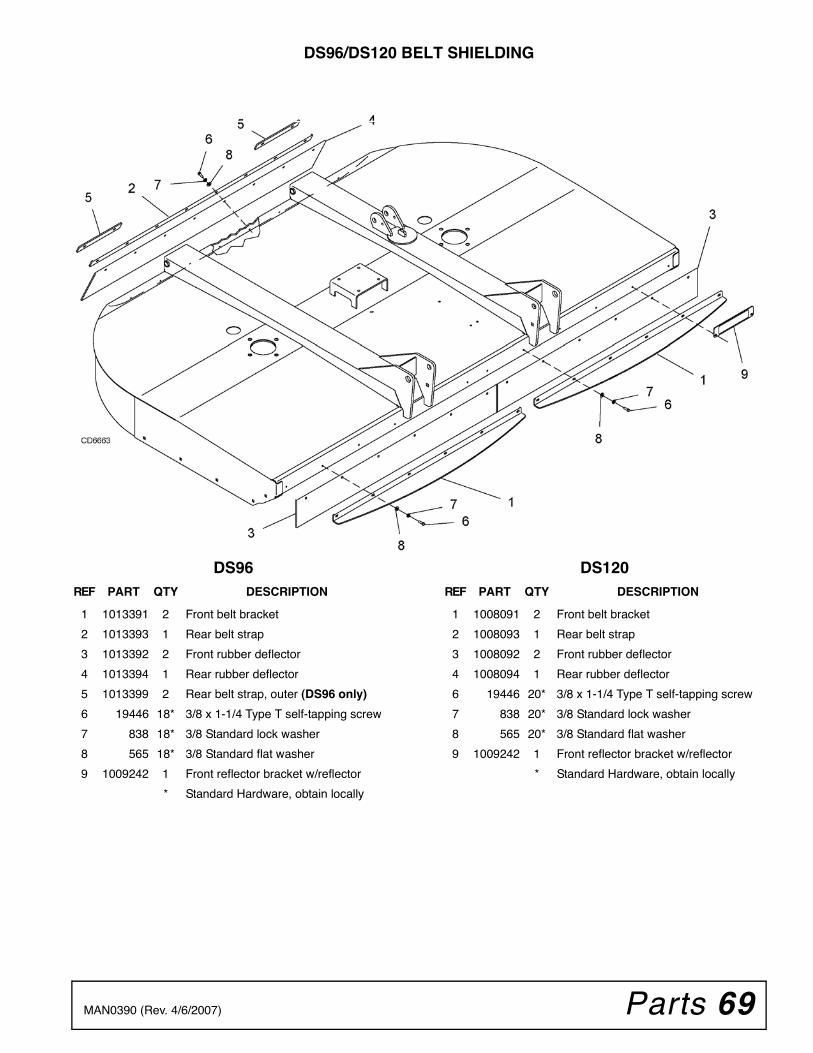
Parts 69MAN0390 (Rev. 4/6/2007)
DS96/DS120 BELT SHIELDING
DS96 DS120REF PART QTY DESCRIPTION
1 1013391 2 Front belt bracket
2 1013393 1 Rear belt strap
3 1013392 2 Front rubber deflector
4 1013394 1 Rear rubber deflector
5 1013399 2 Rear belt strap, outer (DS96 only)
6 19446 18* 3/8 x 1-1/4 Type T self-tapping screw
7 838 18* 3/8 Standard lock washer
8 565 18* 3/8 Standard flat washer
9 1009242 1 Front reflector bracket w/reflector
* Standard Hardware, obtain locally
REF PART QTY DESCRIPTION
1 1008091 2 Front belt bracket
2 1008093 1 Rear belt strap
3 1008092 2 Front rubber deflector
4 1008094 1 Rear rubber deflector
6 19446 20* 3/8 x 1-1/4 Type T self-tapping screw
7 838 20* 3/8 Standard lock washer
8 565 20* 3/8 Standard flat washer
9 1009242 1 Front reflector bracket w/reflector
* Standard Hardware, obtain locally
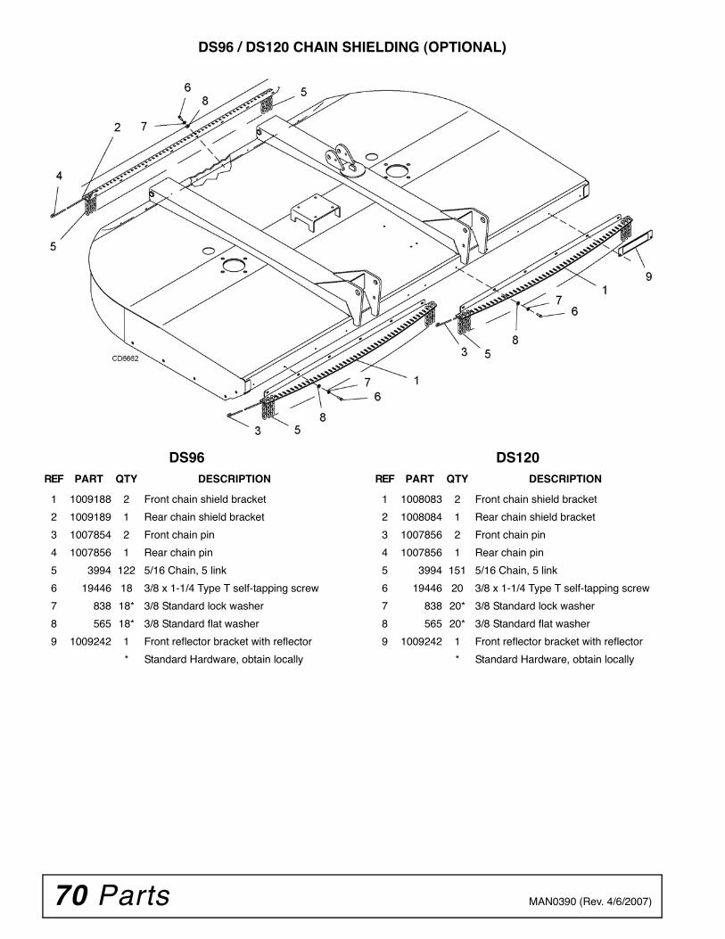
70 Parts MAN0390 (Rev. 4/6/2007)
DS96 / DS120 CHAIN SHIELDING (OPTIONAL)
DS96 DS120REF PART QTY DESCRIPTION
1 1009188 2 Front chain shield bracket
2 1009189 1 Rear chain shield bracket
3 1007854 2 Front chain pin
4 1007856 1 Rear chain pin
5 3994 122 5/16 Chain, 5 link
6 19446 18 3/8 x 1-1/4 Type T self-tapping screw
7 838 18* 3/8 Standard lock washer
8 565 18* 3/8 Standard flat washer
9 1009242 1 Front reflector bracket with reflector
* Standard Hardware, obtain locally
REF PART QTY DESCRIPTION
1 1008083 2 Front chain shield bracket
2 1008084 1 Rear chain shield bracket
3 1007856 2 Front chain pin
4 1007856 1 Rear chain pin
5 3994 151 5/16 Chain, 5 link
6 19446 20 3/8 x 1-1/4 Type T self-tapping screw
7 838 20* 3/8 Standard lock washer
8 565 20* 3/8 Standard flat washer
9 1009242 1 Front reflector bracket with reflector
* Standard Hardware, obtain locally
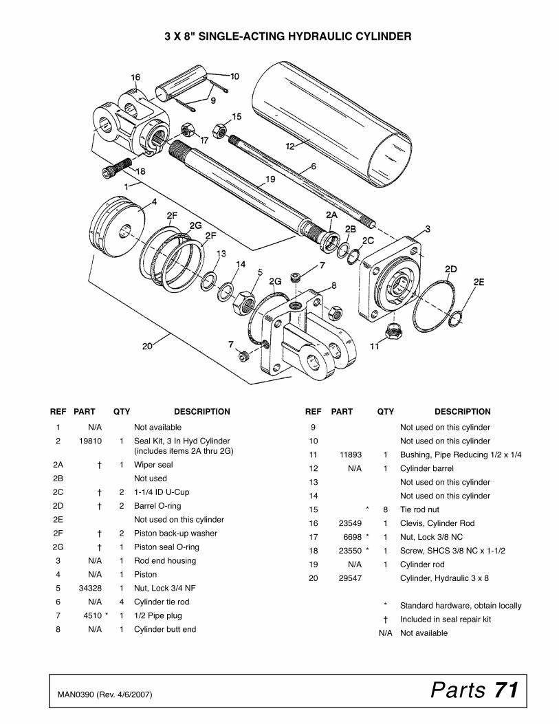
Parts 71MAN0390 (Rev. 4/6/2007)
3 X 8" SINGLE-ACTING HYDRAULIC CYLINDER
REF PART QTY DESCRIPTION
1 N/A Not available
2 19810 1 Seal Kit, 3 In Hyd Cylinder(includes items 2A thru 2G)
2A † 1 Wiper seal
2B Not used
2C † 2 1-1/4 ID U-Cup
2D † 2 Barrel O-ring
2E Not used on this cylinder
2F † 2 Piston back-up washer
2G † 1 Piston seal O-ring
3 N/A 1 Rod end housing
4 N/A 1 Piston
5 34328 1 Nut, Lock 3/4 NF
6 N/A 4 Cylinder tie rod
7 4510 * 1 1/2 Pipe plug
8 N/A 1 Cylinder butt end
REF PART QTY DESCRIPTION
9 Not used on this cylinder
10 Not used on this cylinder
11 11893 1 Bushing, Pipe Reducing 1/2 x 1/4
12 N/A 1 Cylinder barrel
13 Not used on this cylinder
14 Not used on this cylinder
15 * 8 Tie rod nut
16 23549 1 Clevis, Cylinder Rod
17 6698 * 1 Nut, Lock 3/8 NC
18 23550 * 1 Screw, SHCS 3/8 NC x 1-1/2
19 N/A 1 Cylinder rod
20 29547 Cylinder, Hydraulic 3 x 8
* Standard hardware, obtain locally
† Included in seal repair kit
N/A Not available
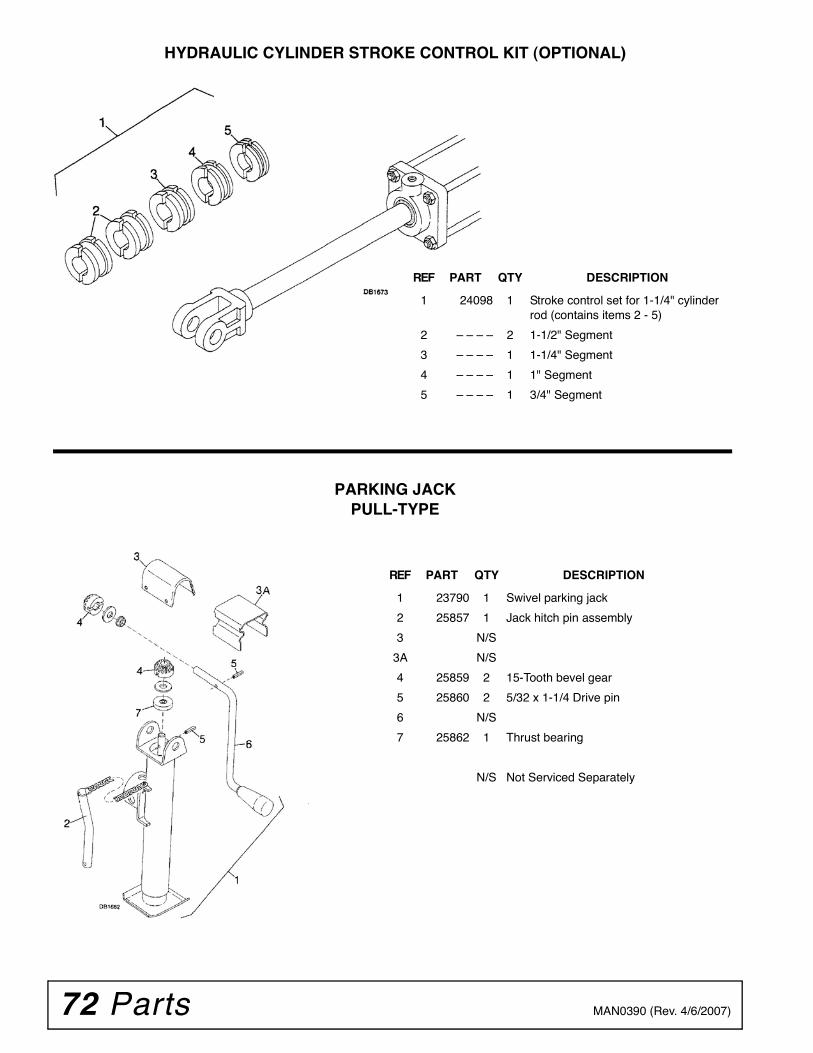
72 Parts MAN0390 (Rev. 4/6/2007)
HYDRAULIC CYLINDER STROKE CONTROL KIT (OPTIONAL)
PARKING JACKPULL-TYPE
REF PART QTY DESCRIPTION
1 24098 1 Stroke control set for 1-1/4" cylinder rod (contains items 2 - 5)
2 – – – – 2 1-1/2" Segment
3 – – – – 1 1-1/4" Segment
4 – – – – 1 1" Segment
5 – – – – 1 3/4" Segment
REF PART QTY DESCRIPTION
1 23790 1 Swivel parking jack
2 25857 1 Jack hitch pin assembly
3 N/S
3A N/S
4 25859 2 15-Tooth bevel gear
5 25860 2 5/32 x 1-1/4 Drive pin
6 N/S
7 25862 1 Thrust bearing
N/S Not Serviced Separately
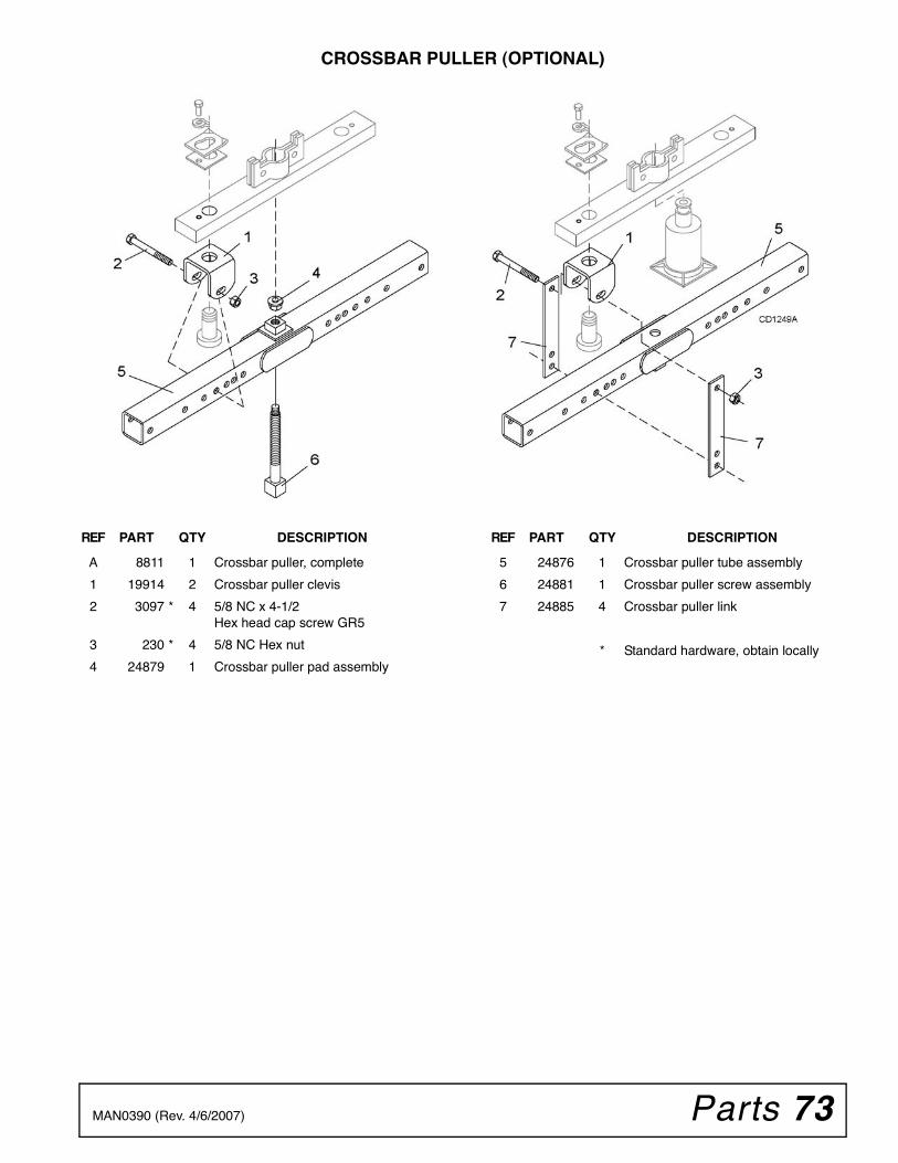
Parts 73MAN0390 (Rev. 4/6/2007)
CROSSBAR PULLER (OPTIONAL)
REF PART QTY DESCRIPTION
A 8811 1 Crossbar puller, complete
1 19914 2 Crossbar puller clevis
2 3097 * 4 5/8 NC x 4-1/2Hex head cap screw GR5
3 230 * 4 5/8 NC Hex nut
4 24879 1 Crossbar puller pad assembly
REF PART QTY DESCRIPTION
5 24876 1 Crossbar puller tube assembly
6 24881 1 Crossbar puller screw assembly
7 24885 4 Crossbar puller link
* Standard hardware, obtain locally
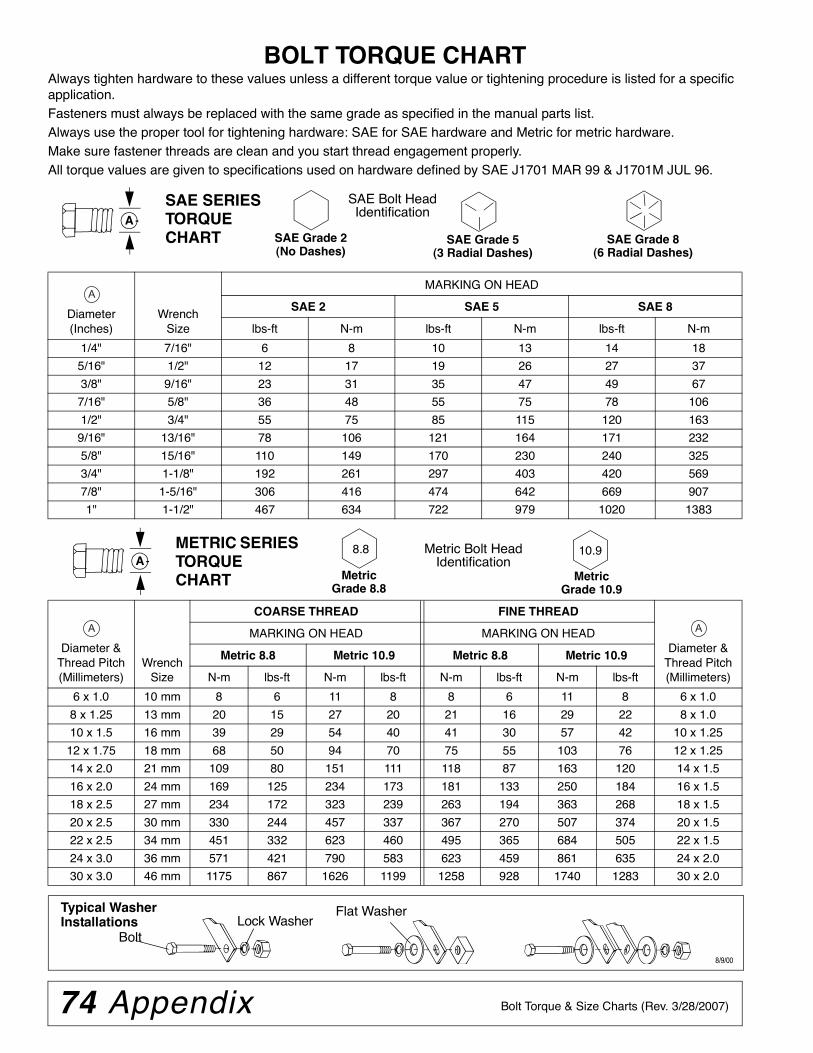
74 Appendix Bolt Torque & Size Charts (Rev. 3/28/2007)
BOLT TORQUE CHARTAlways tighten hardware to these values unless a different torque value or tightening procedure is listed for a specific application.Fasteners must always be replaced with the same grade as specified in the manual parts list.Always use the proper tool for tightening hardware: SAE for SAE hardware and Metric for metric hardware.Make sure fastener threads are clean and you start thread engagement properly. All torque values are given to specifications used on hardware defined by SAE J1701 MAR 99 & J1701M JUL 96.
Diameter (Inches)
WrenchSize
MARKING ON HEAD
SAE 2 SAE 5 SAE 8
lbs-ft N-m lbs-ft N-m lbs-ft N-m
1/4" 7/16" 6 8 10 13 14 18
5/16" 1/2" 12 17 19 26 27 37
3/8" 9/16" 23 31 35 47 49 67
7/16" 5/8" 36 48 55 75 78 106
1/2" 3/4" 55 75 85 115 120 163
9/16" 13/16" 78 106 121 164 171 232
5/8" 15/16" 110 149 170 230 240 325
3/4" 1-1/8" 192 261 297 403 420 569
7/8" 1-5/16" 306 416 474 642 669 907
1" 1-1/2" 467 634 722 979 1020 1383
Diameter & Thread Pitch (Millimeters)
Wrench Size
COARSE THREAD FINE THREAD
Diameter & Thread Pitch (Millimeters)
MARKING ON HEAD MARKING ON HEAD
Metric 8.8 Metric 10.9 Metric 8.8 Metric 10.9
N-m lbs-ft N-m lbs-ft N-m lbs-ft N-m lbs-ft
6 x 1.0 10 mm 8 6 11 8 8 6 11 8 6 x 1.0
8 x 1.25 13 mm 20 15 27 20 21 16 29 22 8 x 1.0
10 x 1.5 16 mm 39 29 54 40 41 30 57 42 10 x 1.25
12 x 1.75 18 mm 68 50 94 70 75 55 103 76 12 x 1.25
14 x 2.0 21 mm 109 80 151 111 118 87 163 120 14 x 1.5
16 x 2.0 24 mm 169 125 234 173 181 133 250 184 16 x 1.5
18 x 2.5 27 mm 234 172 323 239 263 194 363 268 18 x 1.5
20 x 2.5 30 mm 330 244 457 337 367 270 507 374 20 x 1.5
22 x 2.5 34 mm 451 332 623 460 495 365 684 505 22 x 1.5
24 x 3.0 36 mm 571 421 790 583 623 459 861 635 24 x 2.0
30 x 3.0 46 mm 1175 867 1626 1199 1258 928 1740 1283 30 x 2.0
A
SAE SERIES TORQUE CHART
SAE Bolt Head Identification
SAE Grade 2(No Dashes)
SAE Grade 5(3 Radial Dashes)
SAE Grade 8(6 Radial Dashes)
A
METRIC SERIES TORQUE CHART
Metric Bolt Head Identification
8.8
MetricGrade 10.9
10.9
MetricGrade 8.8
A
A A
Typical Washer Installations Lock Washer
Flat Washer
8/9/00
Bolt
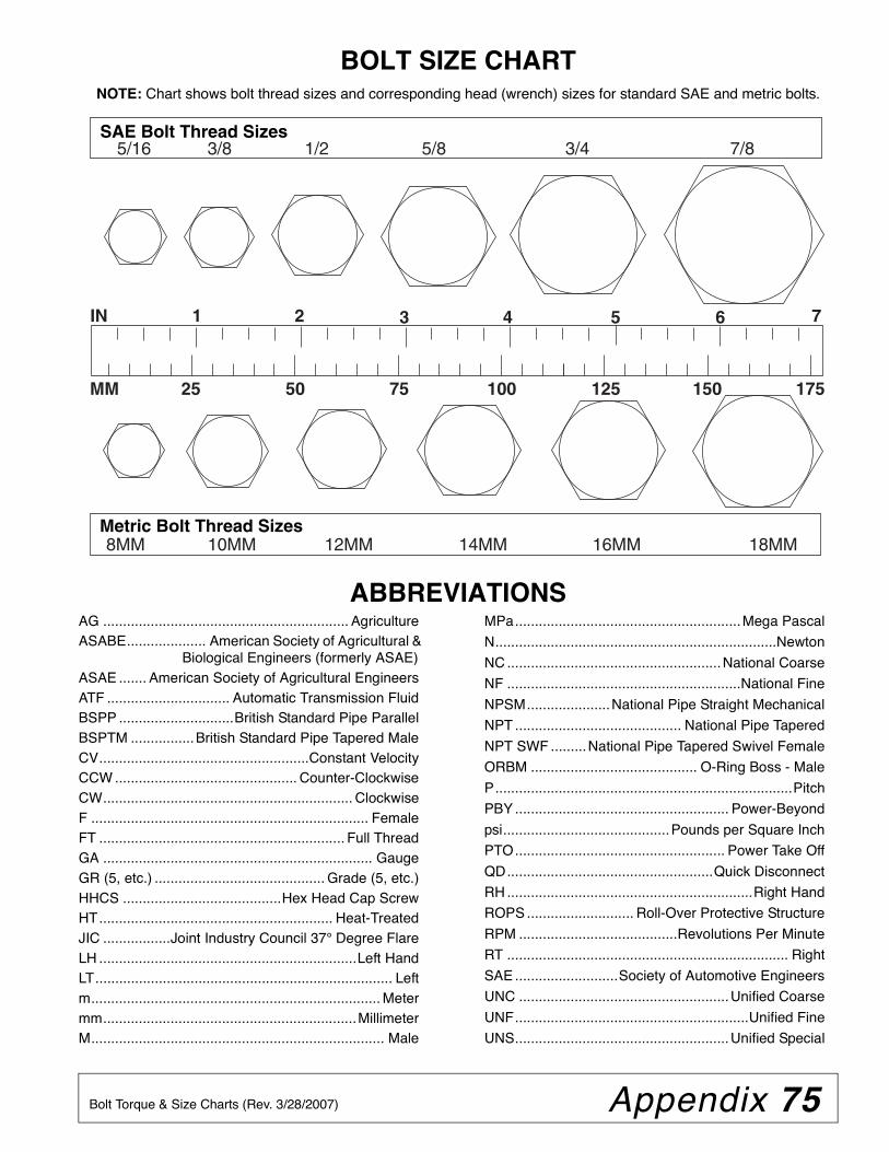
Appendix 75Bolt Torque & Size Charts (Rev. 3/28/2007)
BOLT SIZE CHARTNOTE: Chart shows bolt thread sizes and corresponding head (wrench) sizes for standard SAE and metric bolts.
ABBREVIATIONSAG .............................................................. AgricultureASABE.................... American Society of Agricultural &
Biological Engineers (formerly ASAE)ASAE ....... American Society of Agricultural EngineersATF ............................... Automatic Transmission FluidBSPP .............................British Standard Pipe ParallelBSPTM ................British Standard Pipe Tapered MaleCV.....................................................Constant VelocityCCW .............................................. Counter-ClockwiseCW............................................................... ClockwiseF ...................................................................... FemaleFT .............................................................. Full ThreadGA .................................................................... GaugeGR (5, etc.) ........................................... Grade (5, etc.)HHCS ........................................Hex Head Cap ScrewHT........................................................... Heat-TreatedJIC .................Joint Industry Council 37° Degree FlareLH .................................................................Left HandLT........................................................................... Leftm......................................................................... Metermm................................................................MillimeterM.......................................................................... Male
MPa.........................................................Mega Pascal
N.......................................................................Newton
NC ......................................................National Coarse
NF ...........................................................National Fine
NPSM.....................National Pipe Straight Mechanical
NPT .......................................... National Pipe Tapered
NPT SWF .........National Pipe Tapered Swivel Female
ORBM .......................................... O-Ring Boss - Male
P...........................................................................Pitch
PBY ...................................................... Power-Beyond
psi..........................................Pounds per Square Inch
PTO..................................................... Power Take Off
QD....................................................Quick Disconnect
RH ..............................................................Right Hand
ROPS ........................... Roll-Over Protective Structure
RPM ........................................Revolutions Per Minute
RT ....................................................................... Right
SAE ..........................Society of Automotive Engineers
UNC .....................................................Unified Coarse
UNF...........................................................Unified Fine
UNS......................................................Unified Special
5/16 3/8 1/2 5/8 3/4 7/8SAE Bolt Thread Sizes
MM 25 50 75 100 125 150 175
IN 1 7
Metric Bolt Thread Sizes8MM 18MM14MM12MM10MM 16MM
2 3 4 5 6
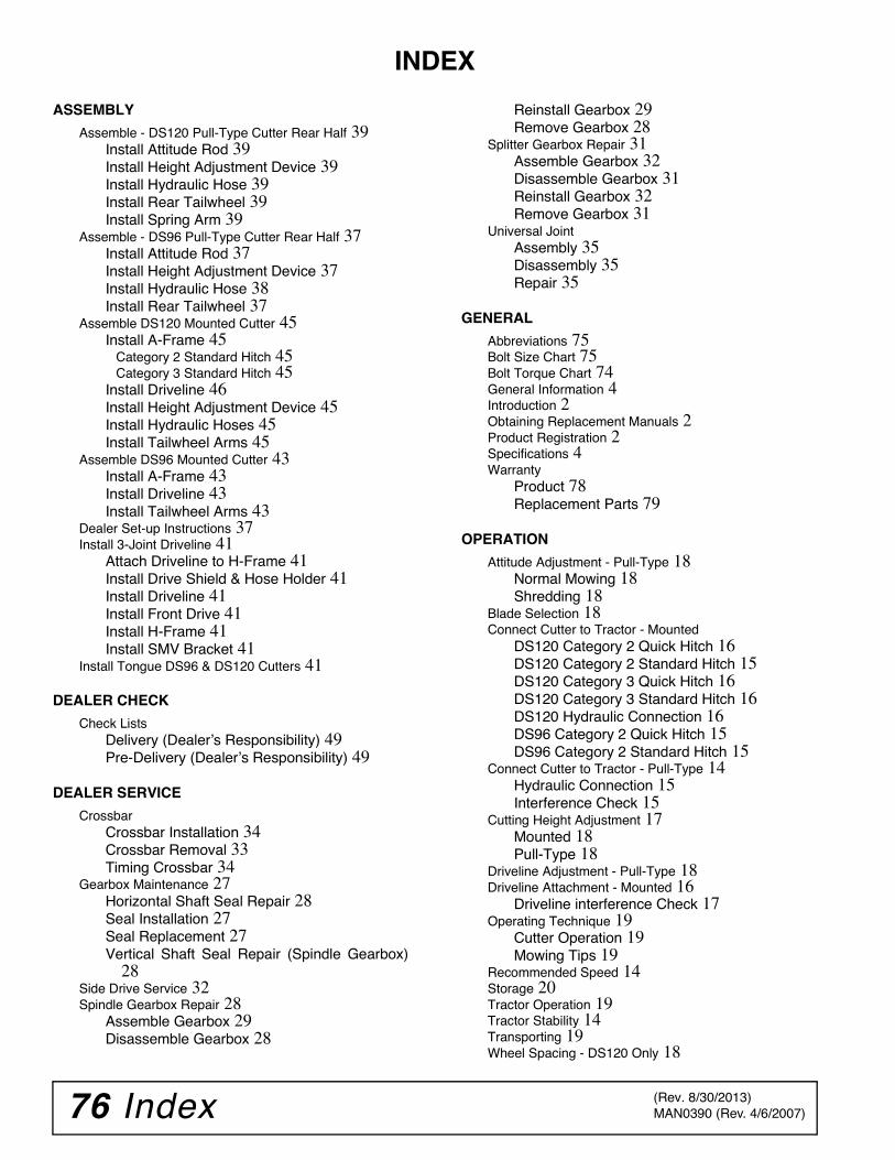
76 Index MAN0390 (Rev. 4/6/2007)
INDEX
ASSEMBLY
Assemble - DS120 Pull-Type Cutter Rear Half 39Install Attitude Rod 39Install Height Adjustment Device 39Install Hydraulic Hose 39Install Rear Tailwheel 39Install Spring Arm 39
Assemble - DS96 Pull-Type Cutter Rear Half 37Install Attitude Rod 37Install Height Adjustment Device 37Install Hydraulic Hose 38Install Rear Tailwheel 37
Assemble DS120 Mounted Cutter 45Install A-Frame 45
Category 2 Standard Hitch 45Category 3 Standard Hitch 45
Install Driveline 46Install Height Adjustment Device 45Install Hydraulic Hoses 45Install Tailwheel Arms 45
Assemble DS96 Mounted Cutter 43Install A-Frame 43Install Driveline 43Install Tailwheel Arms 43
Dealer Set-up Instructions 37Install 3-Joint Driveline 41
Attach Driveline to H-Frame 41Install Drive Shield & Hose Holder 41Install Driveline 41Install Front Drive 41Install H-Frame 41Install SMV Bracket 41
Install Tongue DS96 & DS120 Cutters 41
DEALER CHECK
Check ListsDelivery (Dealer’s Responsibility) 49Pre-Delivery (Dealer’s Responsibility) 49
DEALER SERVICE
CrossbarCrossbar Installation 34Crossbar Removal 33Timing Crossbar 34
Gearbox Maintenance 27Horizontal Shaft Seal Repair 28Seal Installation 27Seal Replacement 27Vertical Shaft Seal Repair (Spindle Gearbox)
28Side Drive Service 32Spindle Gearbox Repair 28
Assemble Gearbox 29Disassemble Gearbox 28
Reinstall Gearbox 29Remove Gearbox 28
Splitter Gearbox Repair 31Assemble Gearbox 32Disassemble Gearbox 31Reinstall Gearbox 32Remove Gearbox 31
Universal JointAssembly 35Disassembly 35Repair 35
GENERAL
Abbreviations 75Bolt Size Chart 75Bolt Torque Chart 74General Information 4Introduction 2Obtaining Replacement Manuals 2Product Registration 2Specifications 4Warranty
Product 78Replacement Parts 79
OPERATION
Attitude Adjustment - Pull-Type 18Normal Mowing 18Shredding 18
Blade Selection 18Connect Cutter to Tractor - Mounted
DS120 Category 2 Quick Hitch 16DS120 Category 2 Standard Hitch 15DS120 Category 3 Quick Hitch 16DS120 Category 3 Standard Hitch 16DS120 Hydraulic Connection 16DS96 Category 2 Quick Hitch 15DS96 Category 2 Standard Hitch 15
Connect Cutter to Tractor - Pull-Type 14Hydraulic Connection 15Interference Check 15
Cutting Height Adjustment 17Mounted 18Pull-Type 18
Driveline Adjustment - Pull-Type 18Driveline Attachment - Mounted 16
Driveline interference Check 17Operating Technique 19
Cutter Operation 19Mowing Tips 19
Recommended Speed 14Storage 20Tractor Operation 19Tractor Stability 14Transporting 19Wheel Spacing - DS120 Only 18
(Rev. 8/30/2013)

Index 77MAN0390 (Rev. 4/6/2007)
OWNER SERVICE
Adjusting Slip Clutch 24Blocking Method 21Cleaning 25Jackstand Placement Diagram 22Lubrication 21
Driveline 21Gearbox 21Lubrication Points Diagram 22
Servicing Blades 22Installing Blades 22Removing Blades 22Sharpening Blades 23
Shielding RepairOptional Chain Shielding 25Rubber Shielding 25
PARTS
Index to Parts Lists 51
SAFETY
Blocking Method 21Check Lists
Delivery (Dealer’s Responsibility) 49Pre-Delivery (Dealer’s Responsibility) 49Pre-Operation (Owner’s Responsibility) 20
Free Mower Safety Video Order Form 5, 6Safety & Instructional Decals 11Safety Rules 7, 8, 9, 10Safety Symbols Explained 2
TROUBLESHOOTING
Troubleshooting 26
(Rev. 8/30/2013)
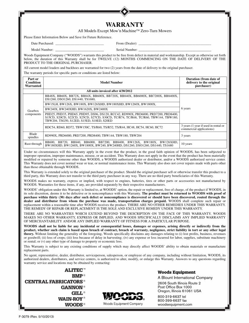
F-3079 (Rev. 5/10/2013)
Woods EquipmentA Blount International Company2606 South Illinois Route 2 Post Office Box 1000Oregon, Illinois 61061 USA
800-319-6637 tel800-399-6637 faxwoodsequipment.com
WARRANTYAll Models Except Mow’n MachineTM Zero-Turn Mowers
Please Enter Information Below and Save for Future Reference.
Date Purchased: ____________________________ From (Dealer): __________________________________________
Model Number: ____________________________ Serial Number: __________________________________________
Woods Equipment Company (“WOODS”) warrants this product to be free from defect in material and workmanship. Except as otherwise set forthbelow, the duration of this Warranty shall be for TWELVE (12) MONTHS COMMENCING ON THE DATE OF DELIVERY OF THEPRODUCT TO THE ORIGINAL PURCHASER.
All current model loaders and backhoes are warranted for two (2) years from the date of delivery to the original purchaser.
The warranty periods for specific parts or conditions are listed below:
Under no circumstances will this Warranty apply in the event that the product, in the good faith opinion of WOODS, has been subjected toimproper operation, improper maintenance, misuse, or an accident. This Warranty does not apply in the event that the product has been materiallymodified or repaired by someone other than WOODS, a WOODS authorized dealer or distributor, and/or a WOODS authorized service center.This Warranty does not cover normal wear or tear, or normal maintenance items. This Warranty also does not cover repairs made with parts otherthan those obtainable through WOODS.
This Warranty is extended solely to the original purchaser of the product. Should the original purchaser sell or otherwise transfer this product to athird party, this Warranty does not transfer to the third party purchaser in any way. There are no third party beneficiaries of this Warranty.
WOODS makes no warranty, express or implied, with respect to engines, batteries, tires or other parts or accessories not manufactured byWOODS. Warranties for these items, if any, are provided separately by their respective manufacturers.
WOODS’ obligation under this Warranty is limited to, at WOODS’ option, the repair or replacement, free of charge, of the product if WOODS, inits sole discretion, deems it to be defective or in noncompliance with this Warranty. The product must be returned to WOODS with proof ofpurchase within thirty (30) days after such defect or noncompliance is discovered or should have been discovered, routed through thedealer and distributor from whom the purchase was made, transportation charges prepaid. WOODS shall complete such repair orreplacement within a reasonable time after WOODS receives the product. THERE ARE NO OTHER REMEDIES UNDER THIS WARRANTY.THE REMEDY OF REPAIR OR REPLACEMENT IS THE SOLE AND EXCLUSIVE REMEDY UNDER THIS WARRANTY.
THERE ARE NO WARRANTIES WHICH EXTEND BEYOND THE DESCRIPTION ON THE FACE OF THIS WARRANTY. WOODSMAKES NO OTHER WARRANTY, EXPRESS OR IMPLIED, AND WOODS SPECIFICALLY DISCLAIMS ANY IMPLIED WARRANTYOF MERCHANTABILITY AND/OR ANY IMPLIED WARRANTY OF FITNESS FOR A PARTICULAR PURPOSE.
WOODS shall not be liable for any incidental or consequential losses, damages or expenses, arising directly or indirectly from theproduct, whether such claim is based upon breach of contract, breach of warranty, negligence, strict liability in tort or any other legaltheory. Without limiting the generality of the foregoing, Woods specifically disclaims any damages relating to (i) lost profits, business, revenuesor goodwill; (ii) loss of crops; (iii) loss because of delay in harvesting; (iv) any expense or loss incurred for labor, supplies, substitute machineryor rental; or (v) any other type of damage to property or economic loss.
This Warranty is subject to any existing conditions of supply which may directly affect WOODS’ ability to obtain materials or manufacturereplacement parts.
No agent, representative, dealer, distributor, serviceperson, salesperson, or employee of any company, including without limitation, WOODS, itsauthorized dealers, distributors, and service centers, is authorized to alter, modify, or enlarge this Warranty. Answers to any questions regardingwarranty service and locations may be obtained by contacting:
Part or Condition Warranted
Model NumberDuration (from date of delivery to the original
purchaser)
All units invoiced after 4/30/2012
Gearbox components
BB48X, BB60X, BB72X, BB84X, BB600X, BB720X, BB840X, BB6000X, BB7200X, BB8400X,DS1260, DSO1260, DS1440, TS1680,
6 yearsBW15LH, BW126X, BW180X, BW126XHD, BW180XHD, BW1260X, BW1800X,
BW240X, BW240XHD, BW1620X, BW2400X
PHD25, PHD35, PHD65, PHD95, DS96, DS120, RCC42, RD990X, PRD6000, PRD7200, PRD8400,S15CD, S20CD, S22CD, S25CD, S27CD, S30CD, TC/R74, TC/R68, TC/R60, TBW144, TBW180,TBW204, TSG50, S12ED, S15ED, S18ED, S20ED
RDC54, RD60, RD72, TBW150C, TS/R60, TS/R52, TS/R44, HC48, HC54, HC60, HC72 3 years (1 year if used in rental or commercial applications)
Blade spindles RD990X, PRD6000, PRD7200, PRD8400, TBW144, TBW180, TBW204 3 years
Rust-through BB600, BB720, BB840, BB6000, BB7200, BB8400, BW126X, BW180X, BW126XHD,BW180XHD, BW1260X, BW1800X, BW240, BW240HD, DS1260, DSO1260, DS1440, TS1680 10 years
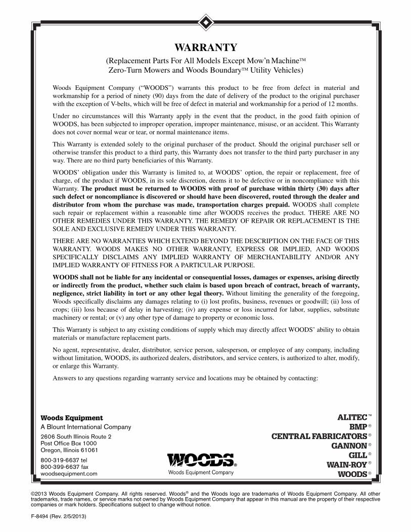
F-8494 (Rev. 2/5/2013)
©2013 Woods Equipment Company. All rights reserved. Woods® and the Woods logo are trademarks of Woods Equipment Company. All othertrademarks, trade names, or service marks not owned by Woods Equipment Company that appear in this manual are the property of their respectivecompanies or mark holders. Specifications subject to change without notice.
Woods EquipmentA Blount International Company2606 South Illinois Route 2 Post Office Box 1000Oregon, Illinois 61061
800-319-6637 tel800-399-6637 faxwoodsequipment.com
WARRANTY(Replacement Parts For All Models Except Mow’n MachineTM
Zero-Turn Mowers and Woods BoundaryTM Utility Vehicles)
Woods Equipment Company (“WOODS”) warrants this product to be free from defect in material andworkmanship for a period of ninety (90) days from the date of delivery of the product to the original purchaserwith the exception of V-belts, which will be free of defect in material and workmanship for a period of 12 months.
Under no circumstances will this Warranty apply in the event that the product, in the good faith opinion ofWOODS, has been subjected to improper operation, improper maintenance, misuse, or an accident. This Warrantydoes not cover normal wear or tear, or normal maintenance items.
This Warranty is extended solely to the original purchaser of the product. Should the original purchaser sell orotherwise transfer this product to a third party, this Warranty does not transfer to the third party purchaser in anyway. There are no third party beneficiaries of this Warranty.
WOODS’ obligation under this Warranty is limited to, at WOODS’ option, the repair or replacement, free ofcharge, of the product if WOODS, in its sole discretion, deems it to be defective or in noncompliance with thisWarranty. The product must be returned to WOODS with proof of purchase within thirty (30) days aftersuch defect or noncompliance is discovered or should have been discovered, routed through the dealer anddistributor from whom the purchase was made, transportation charges prepaid. WOODS shall completesuch repair or replacement within a reasonable time after WOODS receives the product. THERE ARE NOOTHER REMEDIES UNDER THIS WARRANTY. THE REMEDY OF REPAIR OR REPLACEMENT IS THESOLE AND EXCLUSIVE REMEDY UNDER THIS WARRANTY.
THERE ARE NO WARRANTIES WHICH EXTEND BEYOND THE DESCRIPTION ON THE FACE OF THISWARRANTY. WOODS MAKES NO OTHER WARRANTY, EXPRESS OR IMPLIED, AND WOODSSPECIFICALLY DISCLAIMS ANY IMPLIED WARRANTY OF MERCHANTABILITY AND/OR ANYIMPLIED WARRANTY OF FITNESS FOR A PARTICULAR PURPOSE.
WOODS shall not be liable for any incidental or consequential losses, damages or expenses, arising directlyor indirectly from the product, whether such claim is based upon breach of contract, breach of warranty,negligence, strict liability in tort or any other legal theory. Without limiting the generality of the foregoing,Woods specifically disclaims any damages relating to (i) lost profits, business, revenues or goodwill; (ii) loss ofcrops; (iii) loss because of delay in harvesting; (iv) any expense or loss incurred for labor, supplies, substitutemachinery or rental; or (v) any other type of damage to property or economic loss.
This Warranty is subject to any existing conditions of supply which may directly affect WOODS’ ability to obtainmaterials or manufacture replacement parts.
No agent, representative, dealer, distributor, service person, salesperson, or employee of any company, includingwithout limitation, WOODS, its authorized dealers, distributors, and service centers, is authorized to alter, modify,or enlarge this Warranty.
Answers to any questions regarding warranty service and locations may be obtained by contacting:

PART NO.
MAN0390
© 2013 Woods Equipment Company. All rights reserved. Woods® and the Woods logo are trademarks of Woods Equipment Company. All othertrademarks, trade names, or service marks not owned by Woods Equipment Company that appear in this manual are the property of their respec-tive companies or mark holders. Specifications subject to change without notice.
Woods Equipment
A Blount International Company
2606 South Illinois Route 2Post Office Box 1000Oregon, Illinois 61061
800-319-6637 tel800-399-6637 faxwoodsequipment.com