Embed Size (px)
Citation preview
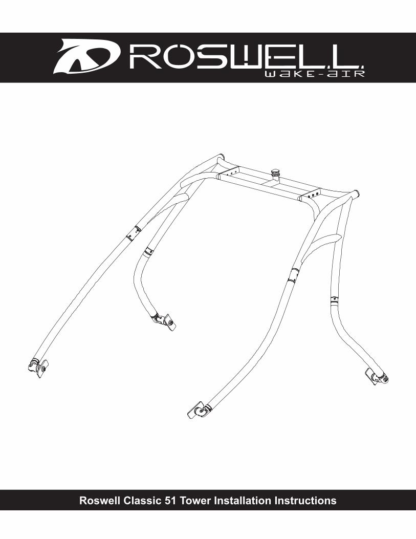
Roswell Classic 51 Tower Installation Instructions
www.roswellwakeair.comRoswell Classic 51 Tower Installation Instructions
1
Thank you for purchasing the best tower in the world. We at Roswell started a revolution in the wakeboard industry back in 1998 and continue to push the boundaries today. We are fully com-mited to going past industry expectations every day to make your wakeboard experience more enjoyable. With the input of our team riders, our goal remains to redefine the wakeboard indus-try day in and day out. We will not be confined to our desks; we are out on the water testing our full line of products to take any unnecessary hassle out of your wakeboard experience. Thanks again for choosing Roswell and keep an eye out for more dominating technology throughout the season...
Sincerely,
Robert OswellOwner, Designer, Wakeboarder
NOTES
● We suggest reading through the installation procedures in their entirety before beginning the actual installation. Failure to do so may result in damage to your boat and possible injury to you and/or your friends. PLEASE FOLLOW THE INSTRUCTIONS PROVIDED BELOW
● This process will require a minimum of three people. The tower needs to be lifted on to the boat to measure placement, so 3 or 4 people makes the job go well and protects your boat at the same time.
● Throughout these instructions, you will see the need for permanent strength Loctite (red). IT IS EXTREMELY IMPORTANT THAT THESE STEPS ARE FOLLOWED
www.roswellwakeair.comRoswell Classic 51 Tower Installation Instructions
2
SETUP
Prepare your workspace:Clear an area near the boat. Make sure there is an unobstructed path from the boat to the setup area. We suggest assembling the tower on a dropcloth to prevent damaging or scratching the finish of the tower. Make sure there are no overhead obstructions (rafters, garage door, chan-deliers etc.)
Unpack the tower: Be careful to avoid marking or scratching when removing the tower from its packaging. As you unpack each part, carefully lay it out on the drop cloth.
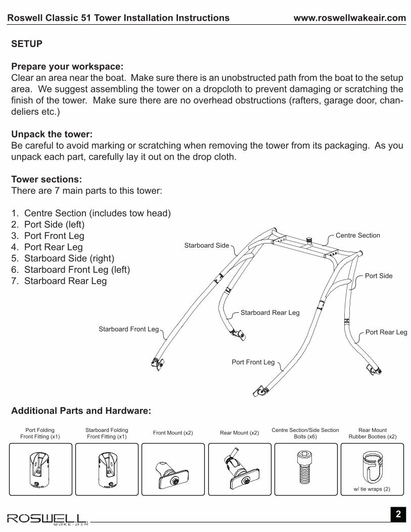
Tower sections:There are 7 main parts to this tower:
1. Centre Section (includes tow head)2. Port Side (left)3. Port Front Leg4. Port Rear Leg5. Starboard Side (right)6. Starboard Front Leg (left)7. Starboard Rear Leg
Additional Parts and Hardware:
Centre Section
Port Side
Port Rear Leg
Port Front Leg
Starboard Front Leg
Starboard Side
Starboard Rear Leg
Port FoldingFront Fitting (x1)
Starboard FoldingFront Fitting (x1)
Front Mount (x2)
w/ tie wraps (2)
Rear Mount (x2) Centre Section/Side SectionBolts (x6)
Rear MountRubber Booties (x2)
www.roswellwakeair.comRoswell Classic 51 Tower Installation Instructions
3
PART 1: TOWER ASSEMBLY
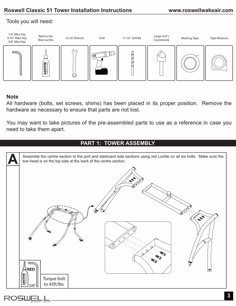
Note All hardware (bolts, set screws, shims) has been placed in its proper position. Remove the hardware as necessary to ensure that parts are not lost.
You may want to take pictures of the pre-assembled parts to use as a reference in case you need to take them apart.
Tools you will need:
Assemble the centre section to the port and starboard side sections using red Loctite on all six bolts. Make sure the tow-head is on the top side at the back of the centre section.
THR
EA
DLO
CK
ER
Red LoctiteBlue Loctite
Drill15/16” Wrench Masking TapeLarge (3/4”)Countersink
1/4” Allen Key5/16“ Allen Key3/8” Allen Key
11/16” Drill Bit Tape Measure
A
3/8”
Torque bolt to 45ft/lbsTH
RE
AD
LOC
KE
R
RED

www.roswellwakeair.comRoswell Classic 51 Tower Installation Instructions
4
Install the female folding fittings to the port and starboard front legs before connecting the front legs to the tower. The legs and fittings are labelled PF and SF to correspond with the fittings on each side section.
Remove the shoulder bolt on the side of the fitting, and loosen the set screw on the other side of the fitting. Remove the shim to access the centre shoulder bolt and then remove the centre shoulder bolt.
The fitting is now ready to be installed on the front leg.
Loosen the three set screws at the bottom of the fitting and slide the fitting on to the leg of the tower. Fasten it with the centre shoulder bolt that was removed in step B and then put the shim back where it was in the fitting. If the fitting is unable to rotate when the bolt is fully tightened, loosen the centre shoul-der bolt 1/8th of a turn. RED LOCTITE MUST BE USED
C D
B
PR = PORT REARPF = PORT FRONTSR = STARBOARD REARSF = STARBOARD FORWARD
Shim
Centre Shoulder Bolt
Side Shoulder Bolt
Female Folding Fitting
Set Screw
Front Leg
Ground
THR
EA
DLO
CK
ER
1/4”
RED
Torque Bolt to 40ft/lbs
Lay the assembled centre and side sections on its back to install the front legs. With the shims in place, slide the female folding fitting onto the male fitting on the front leg of the side section and then insert the bolt to fasten the front leg to the the side section. The opening of the female folding fitting should be facing down or inward. RED LOCTITE MUST BE USED
Front Leg Side Section
1
2
THR
EA
DLO
CK
ER
1/4”
RED
Torque Bolt to 40ft/lbs
1/4”
www.roswellwakeair.comRoswell Classic 51 Tower Installation Instructions
5
E F
At this point your tower should look like this:
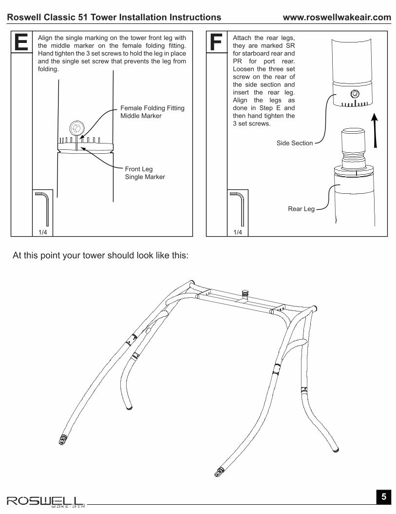
Align the single marking on the tower front leg with the middle marker on the female folding fitting. Hand tighten the 3 set screws to hold the leg in place and the single set screw that prevents the leg from folding.
Female Folding FittingMiddle Marker
Side Section
Rear Leg
Front LegSingle Marker
Attach the rear legs, they are marked SR for starboard rear and PR for port rear. Loosen the three set screw on the rear of the side section and insert the rear leg. Align the legs as done in Step E and then hand tighten the 3 set screws.
1/4 1/4

www.roswellwakeair.comRoswell Classic 51 Tower Installation Instructions
6
G HInstall the front mount by screwing it on to the lap fitting on the end of the front legs.
Front Leg
Front Mount
Rear Mount
Rear Leg
At this point your tower should look like this. Take a few minutes to step back and admire your hard work. You’re half way to the finish line.
NoteSteps G & H are easier when the tower is lying on its back
Install the rear mount by threading the tie-rod end of the preassembled mount into the rear tower leg. Only thread the tie-rod end 1” into the rear leg, thread the nut on tie-rod flush to end of the leg.
1”
5/16”
www.roswellwakeair.comRoswell Classic 51 Tower Installation Instructions
7
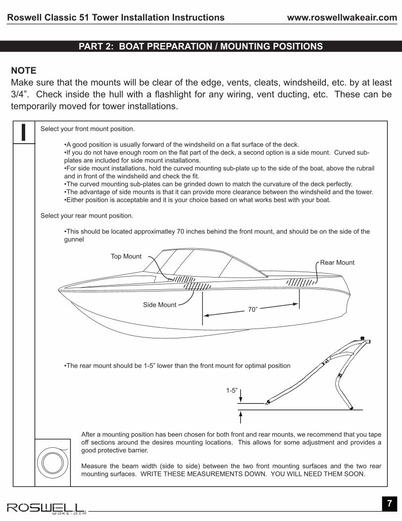
NOTEMake sure that the mounts will be clear of the edge, vents, cleats, windsheild, etc. by at least 3/4”. Check inside the hull with a flashlight for any wiring, vent ducting, etc. These can be temporarily moved for tower installations.
I
PART 2: BOAT PREPARATION / MOUNTING POSITIONS
Select your front mount position. •A good position is usually forward of the windsheild on a flat surface of the deck. •If you do not have enough room on the flat part of the deck, a second option is a side mount. Curved sub- plates are included for side mount installations. •For side mount installations, hold the curved mounting sub-plate up to the side of the boat, above the rubrail and in front of the windsheild and check the fit. •The curved mounting sub-plates can be grinded down to match the curvature of the deck perfectly. •The advantage of side mounts is that it can provide more clearance between the windsheild and the tower. •Either position is acceptable and it is your choice based on what works best with your boat.
Select your rear mount position.
•This should be located approximatley 70 inches behind the front mount, and should be on the side of the gunnel
•The rear mount should be 1-5” lower than the front mount for optimal position
After a mounting position has been chosen for both front and rear mounts, we recommend that you tape off sections around the desires mounting locations. This allows for some adjustment and provides a good protective barrier.
Measure the beam width (side to side) between the two front mounting surfaces and the two rear mounting surfaces. WRITE THESE MEASUREMENTS DOWN. YOU WILL NEED THEM SOON.
Side Mount70”
Rear MountTop Mount
1-5”
www.roswellwakeair.comRoswell Classic 51 Tower Installation Instructions
8
K
J
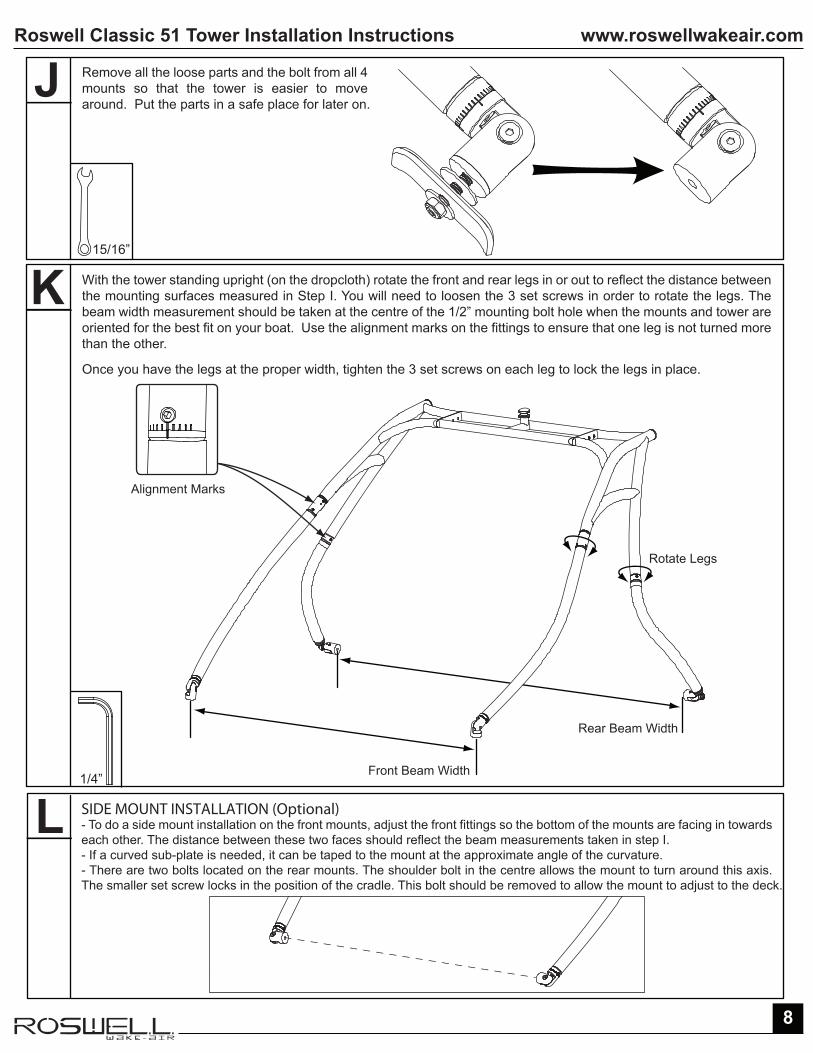
With the tower standing upright (on the dropcloth) rotate the front and rear legs in or out to reflect the distance between the mounting surfaces measured in Step I. You will need to loosen the 3 set screws in order to rotate the legs. The beam width measurement should be taken at the centre of the 1/2” mounting bolt hole when the mounts and tower are oriented for the best fit on your boat. Use the alignment marks on the fittings to ensure that one leg is not turned more than the other.
Once you have the legs at the proper width, tighten the 3 set screws on each leg to lock the legs in place.
Remove all the loose parts and the bolt from all 4 mounts so that the tower is easier to move around. Put the parts in a safe place for later on.
1/4”
15/16”
L SIDE MOUNT INSTALLATION (Optional)- To do a side mount installation on the front mounts, adjust the front fittings so the bottom of the mounts are facing in towards each other. The distance between these two faces should reflect the beam measurements taken in step I.- If a curved sub-plate is needed, it can be taped to the mount at the approximate angle of the curvature.- There are two bolts located on the rear mounts. The shoulder bolt in the centre allows the mount to turn around this axis. The smaller set screw locks in the position of the cradle. This bolt should be removed to allow the mount to adjust to the deck.
Front Beam Width
Rotate Legs
Rear Beam Width
Alignment Marks
www.roswellwakeair.comRoswell Classic 51 Tower Installation Instructions
9
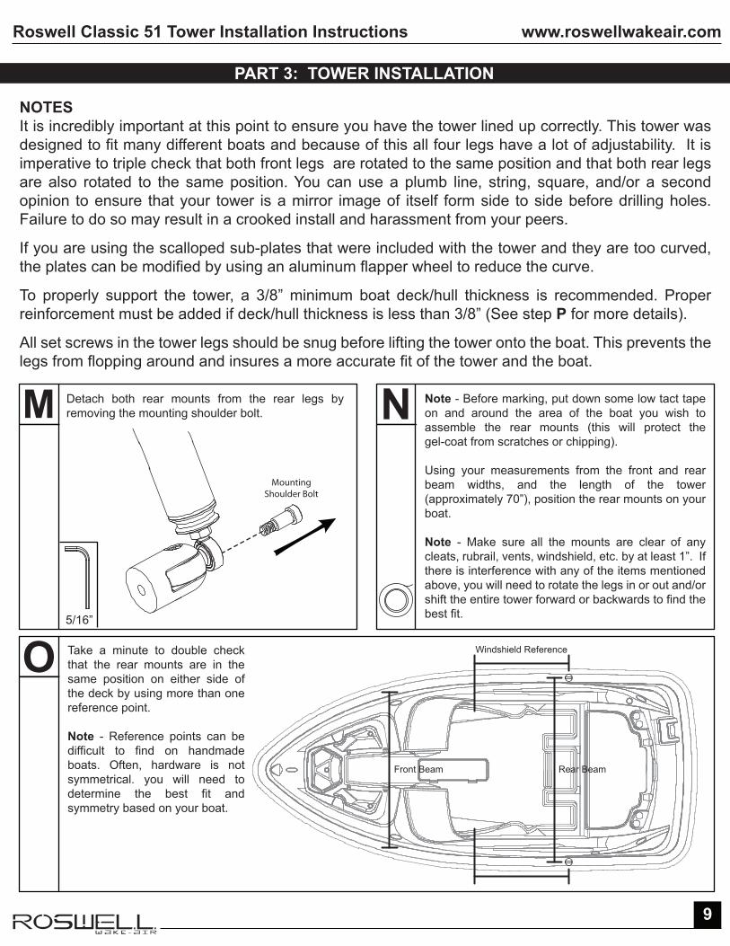
M Detach both rear mounts from the rear legs by removing the mounting shoulder bolt.
PART 3: TOWER INSTALLATION
NOTESIt is incredibly important at this point to ensure you have the tower lined up correctly. This tower was designed to fit many different boats and because of this all four legs have a lot of adjustability. It is imperative to triple check that both front legs are rotated to the same position and that both rear legs are also rotated to the same position. You can use a plumb line, string, square, and/or a second opinion to ensure that your tower is a mirror image of itself form side to side before drilling holes. Failure to do so may result in a crooked install and harassment from your peers.
If you are using the scalloped sub-plates that were included with the tower and they are too curved, the plates can be modified by using an aluminum flapper wheel to reduce the curve.
To properly support the tower, a 3/8” minimum boat deck/hull thickness is recommended. Proper reinforcement must be added if deck/hull thickness is less than 3/8” (See step P for more details).
All set screws in the tower legs should be snug before lifting the tower onto the boat. This prevents the legs from flopping around and insures a more accurate fit of the tower and the boat.
N Note - Before marking, put down some low tact tape on and around the area of the boat you wish to assemble the rear mounts (this will protect the gel-coat from scratches or chipping).
Using your measurements from the front and rear beam widths, and the length of the tower (approximately 70”), position the rear mounts on your boat.
Note - Make sure all the mounts are clear of any cleats, rubrail, vents, windshield, etc. by at least 1”. If there is interference with any of the items mentioned above, you will need to rotate the legs in or out and/or shift the entire tower forward or backwards to find the best fit.
O Take a minute to double check that the rear mounts are in the same position on either side of the deck by using more than one reference point.
Note - Reference points can be difficult to find on handmade boats. Often, hardware is not symmetrical. you will need to determine the best fit and symmetry based on your boat.
Front Beam Rear Beam
Windshield Reference
MountingShoulder Bolt
5/16”

www.roswellwakeair.comRoswell Classic 51 Tower Installation Instructions
10
P Once the best fit position is determined ensuring the front and rear mounts are lined up based on the reference points, mark the position of the front and rear mounts, with a marker, on the taped sections on the boat.
Find the centre of the outlined circle that you traced around the rear mounts. Double check that both rear mounts are square measuring from multiple reference points on the boat (cleat, hull detail, rub rail etc.). Redraw the centre if the 2 mounting positions are not square.
Now that your mounting surfaces are determined, check once again for any obstructions inside the deck. You are about to make holes in your boat.
Note - From boat to boat this may require creating access points behind cushions, storage areas or side paneling.
Q Note - If you need to reinforce your boat deck, now is the ideal time to proceed. Reinforcement procedures on page 15. If you are unsure of the thickness of your boat’s deck/hull, drill a 3/16” pilot hole through the centre mark, proceed with reinforcement procedures if necessary.If everything is clear underneath all 4 mounting areas, drill a hole for both rear feet using an 11/16 drill bit at the centre of the outlined circle you marked in Step O. Hint - Use the rubber gasket supplied with the tower as a template. DO NOT drill holes for the front feet at this point. Countersink these holes to break the edges and prevent gel-coat cracks. Remove the tape after the 2 holes (port and starboard) have been countersunk.Note - Holes must be drilled perpendicular to the boat deck/hull and mounts to provide proper support to the tower.
Re-insert the 5/8” bolt that you removed in Step J back in the rear mounts. RED LOCTITE MUST BE USED. R
Mount Outline
11/16” Hole Countersink
Centre Mark
SECTION VIEW
11/16”
Countersink Hole Gel-coat
Fiberglass3/4”
5/16”THR
EA
DLO
CK
ER
Torque boltto 45ft/lbs
RED

www.roswellwakeair.comRoswell Classic 51 Tower Installation Instructions
11
S
T Now that your mounts are fastened to the boat, lift the tower onto the boat and insert the mounting shoulder bolt through the tie-rod end and into the cradle, on both rear mounts, fasten and tighten well. RED LOCTITE MUST BE USED
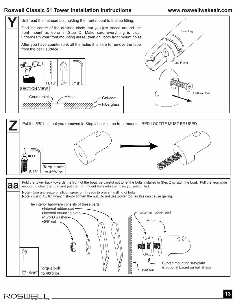
The interior hardware consists of these parts: ●Internal rubber pad ●Internal mounting plate ●1.75”Ø washer ●5/8” nut Mount
External rubber pad
Boat deck/hull
Curved mounting sub-plate is optional based on hull shape
Rear Leg
CradleBoat Deck
Mount
Put the mount bolt through the hole in the hull and have the person inside the boat put the internal hardware on the bolt, as pictured below. Orient the mount so that the cut out slot is vertical (perpendicular to the ground, as shown below). Have the person inside the boat fasten the nut onto the mount bolt. Repeat this on the other side of the boat.
Note - Use anti-seize or silicon spray on threads to prevent galling of bolts.Note - Using 15/16” wrench slowly tighten the nut. Do not use power tool as this can cause galling.
MountingShoulder Bolt
Tie-rod End
15/16”Torque boltto 40ft/lbs
5/16”THR
EA
DLO
CK
ER
RED
Torque boltto 45ft/lbs
90˚
www.roswellwakeair.comRoswell Classic 51 Tower Installation Instructions
12
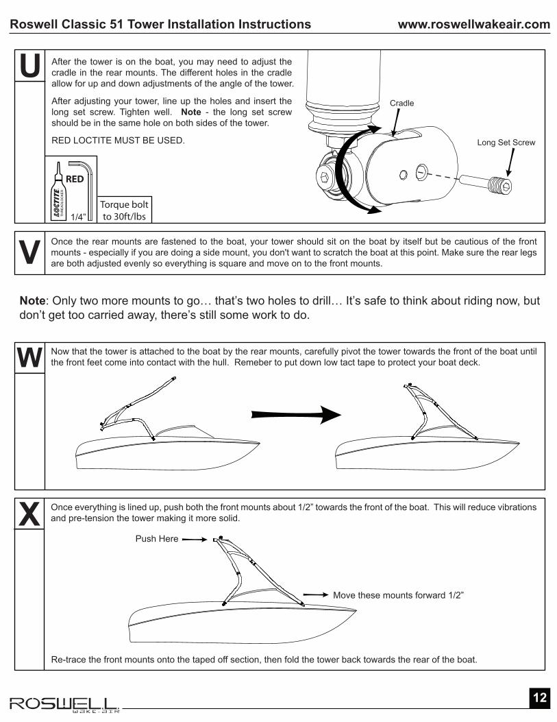
Re-trace the front mounts onto the taped off section, then fold the tower back towards the rear of the boat.
V Once the rear mounts are fastened to the boat, your tower should sit on the boat by itself but be cautious of the front mounts - especially if you are doing a side mount, you don't want to scratch the boat at this point. Make sure the rear legs are both adjusted evenly so everything is square and move on to the front mounts.
W Now that the tower is attached to the boat by the rear mounts, carefully pivot the tower towards the front of the boat until the front feet come into contact with the hull. Remeber to put down low tact tape to protect your boat deck.
Note: Only two more mounts to go… that’s two holes to drill… It’s safe to think about riding now, but don’t get too carried away, there’s still some work to do.
X Once everything is lined up, push both the front mounts about 1/2” towards the front of the boat. This will reduce vibrations and pre-tension the tower making it more solid.
Push Here
Move these mounts forward 1/2”
Long Set Screw
Cradle
U After the tower is on the boat, you may need to adjust the cradle in the rear mounts. The different holes in the cradle allow for up and down adjustments of the angle of the tower.
After adjusting your tower, line up the holes and insert the long set screw. Tighten well. Note - the long set screw should be in the same hole on both sides of the tower.
RED LOCTITE MUST BE USED.
1/4”THR
EA
DLO
CK
ER
RED
Torque boltto 30ft/lbs
www.roswellwakeair.comRoswell Classic 51 Tower Installation Instructions
13
The interior hardware consists of these parts: ●Internal rubber pad ●Internal mounting plate ●1.75”Ø washer ●5/8” nut Mount
Boat hull
Curved mounting sub-plate is optional based on hull shape
External rubber pad
Z Put the 5/8” bolt that you removed in Step J back in the front mounts. RED LOCTITE MUST BE USED.
Y Unthread the flathead bolt holding the front mount to the lap fitting.
Find the centre of the outlined circle that you just traced around the front mount as done in Step Q. Make sure everything is clear underneath your front mounting areas, then drill both front mount holes.
After you have countersunk all the holes it is safe to remove the tape from the deck surface.
SECTION VIEW11/16”
Countersink Hole Gel-coat
Fiberglass
3/4”
Flathead Bolt
Lap Fitting
Front Leg
RED
15/16”Torque boltto 40ft/lbs
Torque boltto 45ft/lbs
aa Fold the tower back towards the front of the boat, be careful not to let the bolts installed in Step Z scratch the boat. Pull the legs wide enough to clear the boat and put the front mount bolts into the holes you just drilled.
Note - Use anti-seize or silicon spray on threads to prevent galling of bolts.Note - Using 15/16” wrench slowly tighten the nut. Do not use power tool as this can cause galling.
5/16”
5/16”
www.roswellwakeair.comRoswell Classic 51 Tower Installation Instructions
14
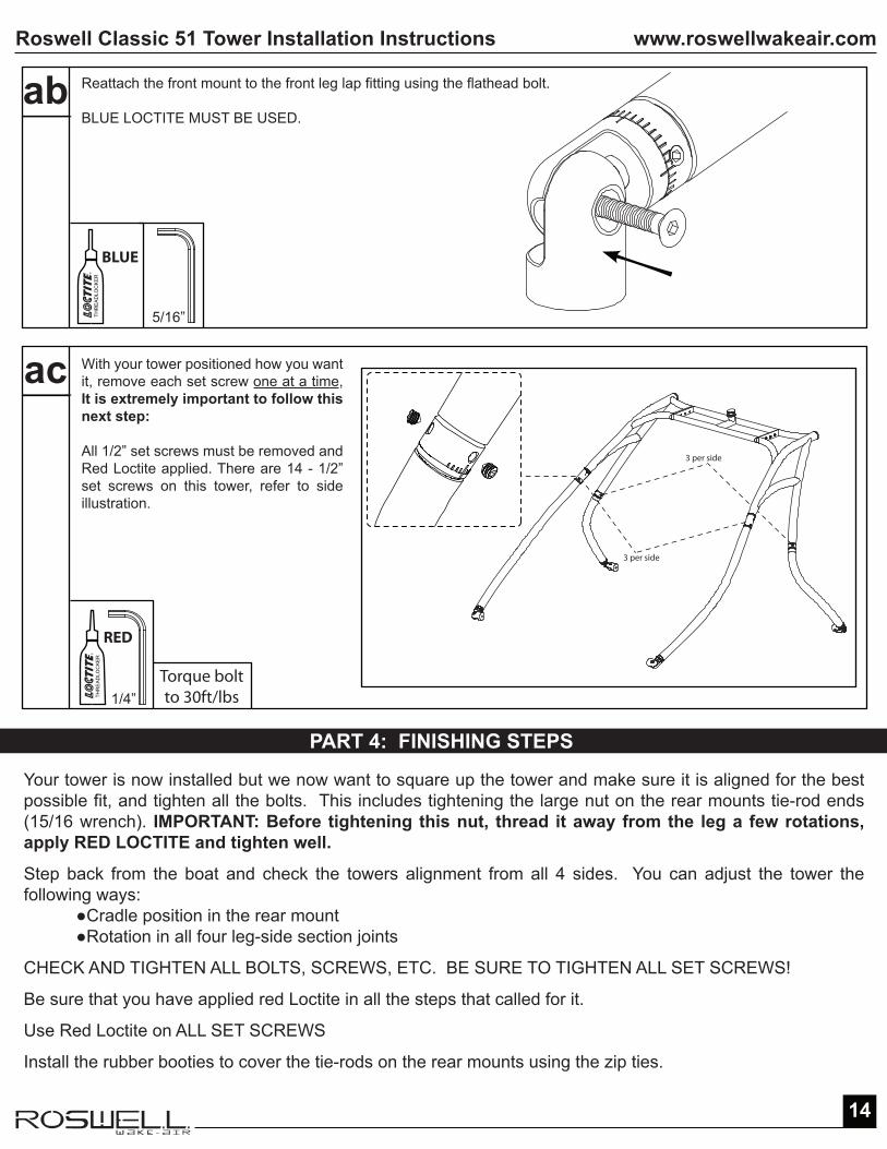
Reattach the front mount to the front leg lap fitting using the flathead bolt.
BLUE LOCTITE MUST BE USED.
ab
With your tower positioned how you want it, remove each set screw one at a time, It is extremely important to follow this next step:
All 1/2” set screws must be removed and Red Loctite applied. There are 14 - 1/2” set screws on this tower, refer to side illustration.
ac
1/4”THR
EA
DLO
CK
ER
3 per side
3 per side
THR
EA
DLO
CK
ER
Torque boltto 30ft/lbs
RED
BLUE
PART 4: FINISHING STEPS
Your tower is now installed but we now want to square up the tower and make sure it is aligned for the best possible fit, and tighten all the bolts. This includes tightening the large nut on the rear mounts tie-rod ends (15/16 wrench). IMPORTANT: Before tightening this nut, thread it away from the leg a few rotations, apply RED LOCTITE and tighten well.
Step back from the boat and check the towers alignment from all 4 sides. You can adjust the tower the following ways: ●Cradle position in the rear mount ●Rotation in all four leg-side section joints
CHECK AND TIGHTEN ALL BOLTS, SCREWS, ETC. BE SURE TO TIGHTEN ALL SET SCREWS!
Be sure that you have applied red Loctite in all the steps that called for it.
Use Red Loctite on ALL SET SCREWS
Install the rubber booties to cover the tie-rods on the rear mounts using the zip ties.
5/16”
www.roswellwakeair.comRoswell Classic 51 Tower Installation Instructions
15
REINFORCEMENT PROCEDUREThe following is a procedure that should be taken to correctly reinforce the location on a fiberglass boat deck for a wakeboard tower mount.
Materials: 40-150 grit sandpaper 3/8” – ½” ABS plastic or marine treated plywood (ideally 4 pieces 5” x 12” or larger if possible) Short strand fiberglass auto body filler (any auto body supply store, NAPA) Catalyst for auto body filler Putty knife Acetone Drill bit (3/16“ & 21/64”) & Counter sink bit 4-#8 wood screws
1. Determine the area best suited for the wakeboard tower mount.2. Look inside the boat (under panels etc.) to make sure you can access the area.3. Take a measurement on the inside of the deck where the reinforcement would be bonded.4. Make sure the area is flat to limit customizing of reinforcement material.5. Cut plastic to the maximum size allowed to be installed in the area.6. Clean off glue or dirt where reinforcement is to be bonded with Acetone.7. Scuff the surface of plastic with 40 – 150 grit sandpaper that will be bonded to boat.8. Use 40 – 150 grit sandpaper (which ever is available) to scuff the fiberglass surface on the inside of the deck. This will make better bonding.9. Using a 3/16 drill bit, drill a hole centered on the mounting bolt hole.10. Mix enough short strand fiberglass auto body filler and catalyst to butter the scuffed surface of 2 of the plastic reinforce blocks 11. Butter ¼” – 3/8” thick of auto body filler onto the scuffed surface of the plastic.12. Push the plastic with filler onto the scuffed area of the boat deck with a side to side and up and down motion. This will create a suction effect.13. Insert a #8 screw into the centre hole you just drilled, securing the plastic to the boat deck.14. Wipe up any excess putty as it appears with acetone and a cloth.15. Follow steps 9 – 14 for the other side of the boat.16. Material should be ready to drill in a couple of hours depending on the amount of catalyst used.
NOTE: The more catalyst used in the filler will accelerate the cure time, but will make the bond more brittle. The best mix would be ¾” cup of auto body filler mixed with 2”-3” string of catalyst. Use a putty knife and fold the two materials together until colors have mixed evenly.
ROSWELL PRODUCT STRUCTURE 3 YEARS- All welds - Cast, machined extruded parts- Hardware
ROSWELL PRODUCT FINISH AND WEARABLES 1 YEAR- Fading- Blistering- Peeling- Rusting- Speakers- Lights- Wiring
For Warranty information please contact: [email protected]
QUICK NOTE WARRANTY PERIOD CHART
www.roswellwakeair.comRoswell Classic 51 Tower Installation Instructions
16
WARRANTY
3 YEAR LIMITED PARTS AND STRUCTURE WARRANTY- Roswell manufactured products are warranted to be free from defects in materials and workmanship for a period of 3 years from the first retail sale date. Warranty will be determined by Roswell’s warranty department only and will at our discretion be repaired or replaced within the first three years.
Excluded in the limited warranty is damage due to misuse or improper care. If a Roswell Wake Air product fails due to defective materials or workmanship after the original warranty period, it will, at manufacturer’s option, be repaired or replaced for a charge.
This limited 3 year warranty is in effect as long as the original owner keeps the product and is not transferable.
3 YEAR LIMITED PARTS AND STRUCTURE WARRANTY- Roswell Wake Air warrants that for a period of 3 years from the date the tower is sold at retail, that Roswell will repair directly, or supply parts for the repair of any material cracks, fractures or structural failures that are a result of a manufacturing defect. Any modifications or improper use, not approved in writing by Roswell Wake Air, shall void this warranty. Roswell Wake Air is not responsible for personal injury or damage to the boat caused by the use of any Roswell product. No dealer, retailer or manufacturer is the agent of Roswell Wake Air and may not assume for Roswell any liability in connection with this warranty. This warranty is in lieu of all other warranties, expressed or implied, including any warranty of merchantability or of fitness for a particular purpose.
Defects must be reported within 30 days of receipt.
1 YEAR LIMITED ESTHETIC WARRANTY- Roswell products are warranted to be free from defects in the clear coat, paint and anodizing for a period of 1 year from customer purchase date. Warranty will be determined by Roswell’s warranty department only and will at our discretion be repaired or replaced within the first year.
Excluded in the limited aesthetics warranty is damage due to misuse or improper care. Coated surfaces as well as all hardware corrosion/oxidation are specifically excluded from the 1 year warranty as their care, maintenance and used environment cannot be controlled by Roswell Wake Air. If the coating has an issue due to defective materials or workmanship after the original 1 year warranty period, it will, at manufacturer’s option, be repaired or replaced for a charge.
This limited 1 year warranty is in effect as long as the original owner keeps the product and is not transferable.
DAMAGE DUE TO MISUSE OR IMPROPER CARE IS EXCLUDED.Never modify the tower. Use only Roswell Wake-Air brand aftermarket accessories such as hanging speakers, light bars or mirror arms; all available from your authorized Roswell dealer. MODIFICATIONS OR UNAPPROVED ACCESSORIES MAY VOID THE WARRANTY AND OR RESULT IN FAILURE OF THE PRODUCT.Disassembly and/or repair must only be performed by an authorized Roswell dealer. UNAUTHORIZED SERVICE WILL RENDER THE WARRANTY NULL AND VOID, AND COULD CAUSE THE TOWER TO MALFUNCTION.

www.roswellwakeair.comRoswell Classic 51 Tower Installation Instructions
17
WARNING & DISCLAIMER
●This product is to be used for the sole purpose of wakeboarding, wakesurfing, airchairing, and kneeboarding.
●Ensure that all set screws, nuts, and bolts are in place and secure prior to using your product.
●Periodically check that all bolts, screws, and nuts are tight. Even with Loctite they may loosen over time.
●Never travel at high speeds (i.e. towing the boat on a trailer) with wakeboards, wakesurfers, skis, etc. in the racks. If you own quick release racks or speakers, we suggest sliding them off during travel and stowing them safely in the boat or vehicle.
●Be cautious when driving your boat on the water or on a trailer if you have board racks. They may decrease your clearance into a garage or slip.
●Please feel free to contact us with any questions regarding your new product. A Roswell representative can be reached at (780) 962-0868 or by email at: [email protected]
Roswell Classic 51 Tower
OWNER’S MANUAL

www.roswellwakeair.comRoswell Classic 51 Tower Owner’s Manual
19
OWNER’S MANUAL
PLEASE READ COMPLETELY TO GAIN A FULL UNDERSTANDING OF THE OWNER’S MANUAL BEFORE OPERATING THIS PRODUCT
THANK YOU FOR PURCHASING YOUR NEW TOWER. HERE AT ROSWELL WE APPRECIATE YOUR BUSINESS AND STRIVE TO MAKE YOUR ON-WATER TIME THE BEST IT’S EVER BEEN. WHAT FOLLOWS IS A GUIDE TO HELP YOU USE YOUR TOWER TO ITS FULL POTENTIAL.
Should you experience problems that cannot be resolved by an authorized Roswell Wake-Air dealer, please contact our customer service centre at (780) 962-0868.
THIS MANUAL CONTAINS IMPORTANT INFORMATION FOR THE PROPER USE AND CARE FOR YOUR ROSWELL WAKE-AIR TOWER. ROSWELL TOWERS ARE DESIGNED WITH MANY FEATURES THAT ARE UNIQUE TO THE ROSWELL
LINE. IT IS THUS VERY IMPORTANT TO CAREFULLY READ THE INSTRUCTIONS PROVIDED IN THIS MANUAL IN ORDER TO UNDERSTAND THE CORRECT USE OF YOUR TOWER.
DISREGARDING ANY OF THE SAFETY PRECAUTIONS, INSTRUCTIONS CONTAINED IN THIS OWNER’S MANUAL, OR ANY OF THE PRODUCT
WARNING LABELS MAY CAUSE INJURY OR DEATH.
Notice – This owner’s manual has been prepared to familiarize the owner/operator with the various features of the tower, maintenance, and safe operating instructions. This information is essential for the proper use of this product. We are pleased to receive any comments on the content and format of this manual, as well as the product warning labels.
www.roswellwakeair.comRoswell Classic 51 Tower Owner’s Manual
20
OWNER’S MANUAL
GENERAL WARNINGS
Before using your Roswell tower it is important to completely read and understand all the instructions provided in this owner’s manual, any accompanying inserts, and labels affixed to the tower. If you have any questions or do not fully understand these instructions, please consult your authorized Roswell dealer or contact us directly at [email protected] or contact our customer service centre.
Before each use, perform a complete pre-ride inspection following the instructions provided in this manual. Check the entire tower to confirm there are no signs of damage. Check to ensure the tightness of all bolts. Bolts must be tightened after each use on the water. IF ANY SIGNS OF DAMAGE OR MALFUNCTION ARE FOUND, DO NOT ATTACH ANYTHING TO THE TOWER UNTIL IT HAS BEEN INSPECTED AND SERVICED BY AN AUTHORIZED ROSWELL DEALER. FAILURE TO FOLLOW THESE GUIDELINES MAY INCREASE THE RISK OF ACCIDENTS OR EQUIPMENT DAMAGE TO THE TOWER AND/OR BOAT.
The tower is intended to tow a maximum of two wake boarders at one time and no more than 400lbs (181kg) collectively.
Do not boat under any solid object such as a bridge or overpass without first checking the necessary clearance with the tower on the boat.
Never hang from the tower. Do not climb or sit on the tower.
Never attach a tow rope to anything other than the tow head.
Be aware of the tow rope at all times. Ensure that it is not attached to anything on the tower other than the tow head, and that the rope is clear of any cleats or objects on the boat before pulling the rider up and out of the water. Obey all boating laws and regulations in your area.
www.roswellwakeair.comRoswell Classic 51 Tower Owner’s Manual
21
OWNER’S MANUAL
Follow the Water Sports Responsibility Code as follows:
Water Sports Responsibility Code
Be aware that there are elements of risk in boating, skiing, and riding that common sense and personal awareness can help reduce. Know your ability level and stay within it.
To increase your enjoyment of the sport, follow the “Water Sports Responsibility Code”.
It is your responsibility to:
Familiarize yourself with all applicable laws, the risks inherent in the sport, and the proper use of equipment.Know the waterways where you will be skiing or riding. Do not ski or ride in shallow water, near shore, docks, pilings, swimmers, or other watercraft. Boaters are responsible for the wake they leave behind and any damage cause by that wake.Always have a person other than the boat driver as an observer and agree on hand signals before starting.Always wear a U.S. Coast Guard type III (PFD) life vest.Read your owner’s manual and inspect your equipment prior to use.Ski or ride within your limits. Always ski or ride in control and at speeds appropriate for your ability.Always turn ignition off when anyone is near watercraft power drive unit.Carbon Monoxide (CO) poisoning from engine exhaust may cause injury or death.Never “Platform Drag” or touch a swim platform while the engine is running.Not operate watercraft, ski or ride under the influence of alcohol or drugs.Respect the waterways that we have access to and acknowledge that water is a precious resource we are allowed to use – water use is not a right, it can be taken away!
Water Sports Industry Association2010

www.roswellwakeair.comRoswell Classic 51 Tower Owner’s Manual
22
OWNER’S MANUAL
GENERAL TOWER MAINTENANCECheck all tower hardware before every use on the water. We recommend keeping a set of Allan wrenches on your boat for this purpose.
Do not use the board racks as entry/exit handles to get in and out of the boat – they are not designed for this purpose.
Check the clearance between your tower and any overhead obstacles including bridges, canals etc.
Always check the clearance when storing your boat in a garage etc.
NEVER USE CLEANERS ON YOUR TOWER!
COLLAPSING YOUR TOWER1. Using a 5/16” allen key unthread and pull back both flathead bolts from the front mounts of the tower .
2. With both knobs pulled back, carefully fold the tower backwards – pay attention as the tower will be top heavy. If you have speakers on the tower note the contact points of the tower.

www.roswellwakeair.comRoswell Classic 51 Tower Owner’s Manual
23
OWNER’S MANUAL
3. You may need to pad the contact points to prevent damage to the tower, gel coat or upholstery.
4. With a 1/4” allan key loosen the set screw on the front mount as pictured below.
5. With the set screw loosened both legs will now fold inward as pictured below.
6. To set the tower back up reverse the steps and ensure the flathead bolts and set screws are secured before each use.