Embed Size (px)
Citation preview
HBH SeriesRedundant Valve Systems Hydraulic Block & StopSafety Valves
Operating Instructions
www.rosscontrols.com
RC-HBH-OI 04.2020 EN

HBH Series Operating Instructions
2 www.rosscontrols.com
ORDER KEY (Example)
PRODUCT LABEL IDENTIFICATION
HBH D D XX 682F B A E X A
Series Revision Level
Pressure ReliefNo Pressure Relief Valve
BodySize Flow Rate Port Size Port
Thread/Type
D25 0 to 90 gpm1-1/2 Code 62 Flange 682F
2 Code 62 Flange 692F
D32 0 to 145 gpm 2 Code 62 Flange 792F
Valve TypeDouble
MaterialDuctile Iron
Voltage24 volts DC
CommunicationNone
Seal TypeBuna-N
MonitoringExternal
ISO Size Weight lb (kg)
D25 112.3 (50.9)
D32 142.8 (64.8)
SCHEMATIC
2A
Z1 Z2X
G
B
A
YC
2B
Z1Z2 X
G
B
A
Y C
3A
P1
X
YP2
X
Y
3B
MP2M-2MP1
5A 5BXX
WIRING DIAGRAM Inductive Position Switch Connector
1 = Supply +24 volts DC2 = Output Signal NC3 = Ground4 = Output Signal NO
NO NC
1
43
2

HBH Series Operating Instructions
www.rosscontrols.com 3
Body Size D25
Ports ListID NameP1 1.500 MT 62P2 1.500 MT 62X SAE # 6Y SAE # 6
MP1 SAE # 6M-M SAE # 6MP2 SAE # 6M-X SAE # 6
Body Size D32
Ports ListID NameP1 2.000 MT 62P2 2.000 MT 62X SAE # 6Y SAE # 6
MP1 SAE # 6M-M SAE # 6MP2 SAE # 6M-X SAE # 6
MOUNTING INFORMATION AND OVERALL DIMENSIONS (inches/mm)
14.2
[360
]~
(4X) M12 X 1.75
M10 X 1.5 Lifting Bolt Hole
(4X) M12 X 1.75
(4X) M16 X 2.0
(4X) M16 X 2.0
10.00 [254.0]
4.25
[108
.0]
6.00
[152
.4]
0.69 [17.5]
3.00 [76.2]
5.25 [133.4]6.00 [152.4]
2.25 [57.2]
7.75 [196.9]
10.00 [254.0]
0.50 [12.7]
5.50
[139
.7]
6.00
[152
.4]
(2X) Tamper Kit
B
B
9.2 [233.7]~
3.13 [79.4] Both Ends
1.44
[36.
5] B
oth
End
s
9.00 [228.6] 0.50 [12.7]
5.00
[127
.0]
0.50
[12.
7]
Position Switch Sensor Connector
Solenoid Pilot
4.09
[104
.0]
6.00
[152
.4]
3.00 [76.2]
6.00 [152.4]
13.8
[349
.4]
~
9.2 [233.7]~
10.00 [254.0] 1.00 [25.4]
5.00
[127
.0]
0.50
[12.
7]
(4X) M12 X 1.75
12.00 [304.8]
(4X) M20 X 2.50
(4X) M20 X 2.50
(4X) M12 X 1.750.
50 [1
2.7]
5.00
[127
.0]
2.25 [57.2]
7.50 [190.5]
7.8
[197
.0]
~
1.2 [31.4]~
1.75
[44.
5]
Bot
h E
nds
3.81 [96.8] Both Ends
Bottom ViewPosition Switch
Sensor Connector
SolenoidPilot

HBH Series Operating Instructions
4 www.rosscontrols.com
1. About this DocumentationThese instructions contain important information for the safe and appropriate assembly and commissioning of the product.
f Read these instructions all the way through, particularly section 6 “Notes on Safety,” before working with the product.
For more information see last page for contact information, or visit www.rosscontrols.com.
f In addition, observe all applicable local and national regulations on accident prevention and on environmental protection.
1.1. Warning Notices in these Operating InstructionsIn these operating instructions, warning notices precede sections with handling requirements which incur risks of personal injury or material damage.Warnings are structured as follows:
SIGNAL WORDType or source of hazard!Consequences
f Measures to avert danger
• Warning triangle: Indicates a risk of fatal or severe injuries.• Signal word: Indicates the severity of the danger.• Type or source of hazard: States the type of danger or the source of the hazard.• Consequences: Describes possible consequences of ignoring the warning.• Measures to avert danger: Indicates how to avoid the danger. It is essential that
the measures to avert danger are complied with.
DANGERIndicates an imminent and serious danger that will result in severe or even fatal injury if you fail to avoid it.
WARNINGIndicates a possible danger that could result in severe or even fatal injury if you fail to avoid it.
CAUTIONIndicates a danger that may result in minor to moderate injuries if you fail to avoid it.
ATTENTION Indicates potential property damage that may be incurred by the product or its surroundings if you fail to avoid it.
2. Product IdentificationThe valve assembly is marked with Model Number, Revision level, and a serial number which can be used to identify date of manufacture and location. Please contact ROSS Controls for further information.
Product label identification & product key identification example, see page 2.
3. Prerequisites for Use of the Product f Make these operating instructions available to the engineer and assembly
technician of the machine/system in which the product will be used. f Keep these operating instructions for the entire product life cycle.
3.1. Qualified PersonnelAssembly, installation, commissioning, maintenance, and decommissioning should only be carried out by qualified personnel that have the required knowledge of and experience in dealing with electrical and hydraulic control technology.
All work may be performed only by properly trained and qualified individuals who have been specifically instructed for the tasks assigned to them. The levels of responsibility of personnel are to be clearly delineated by the owner/operator. Protective clothing and gear is to be worn when performing all work. The relevant safety and accident prevention regulations are to be adhered to. Any special safety requirements specified in the documentation for the unit/system are to be complied with.
4. Package ContentsItems included:• Block & Stop control valve system• Operating instructions
5. Service, Repair, and Maintenance f In case of technical problems or a required repair, please contact your local
ROSS® representative. f Checks should be conducted once a month to ensure valves are in functioning order.
5.1. Maintenance
WARNING- All activities of maintenance must be conducted by competent and qualified staff- Always depressurize the relevant part of the system before any maintenance operation on the hydraulic power unit.
When/if a valve is replaced; a basic functional test should be performed (see 8.1 Test Procedure).
It is important that all the check-up operations, even if simple, are programmed and reported on specific maintenance program schedules.
Before the inspection, cleaning should be undertaken if necessary.
WARNING- Always ensure cleanliness when working on the HBH Valve. - Do not perform maintenance with the equipment functioning!- Penetrating dirt and liquids will cause faults!- Safe function of the HBH valve is not ensured when operated with contaminated fluid. - Certain solvents and aggressive cleaning agents or detergents may damage the
seals on the HBH valve and make them age faster.- Never use solvents or aggressive detergents as these can cause damage to the
hydraulic system and seals!- The water pressure of a high-pressure cleaner can damage the seals of the HBH valve.- Do not use a high-pressure cleaner.- Pay attention to prevent detergent penetration into the HBH valve.- Check that all seals and electrical plug connections are firmly fitted to prevent the
penetration of detergents.
6. Notes on SafetyThe product has been manufactured according to the accepted rules of current technology. There is risk of injury or damage if the following safety instructions and warnings given in this instruction manual are not observed.
6.1. Intended UseThe HBH Series Block & Stop Control systems are safety components designed and manufactured in accordance with Machinery Directive 2006/42/EC.
The HBH system is comprised of two single valves which make it a redundant design for meeting the needs and requirements of safe hydraulic Block & Stop applications. Typically, these systems are designed to meet Category 3, PL d, SIL 2 applications if properly implemented into the safety control & monitoring system.
The HBH Series Block & Stop system is designed to allow the flow of hydraulic fluid into or out of a cylinder or to block the flow in order to stop cylinder motion (Block & Stop) when needed.
During normal operation the HBH system is held actuated, allowing the flow of hydraulic fluid through the HBH unit from inlet to outlet. In a situation when immediate pressure and flow shut-off is needed, the HBH Series Block & Stop system can be turned off to provide an immediate flow and pressure blocking action.
The HBH Series Block & Stop systems are designed to be externally monitored by a safety control & monitoring system for safe, redundant operation of the valves. Each single valve is equipped with a PNP inductive position switch. Monitoring both of these switches on each actuation and de-actuation of the HBH Block & Stop system provides a diagnostic coverage up to 90%. Monitoring of these switches must be done by an external monitoring system.
The unit cannot be used by itself. It is designed for installation in a machine. ROSS and its suppliers will assume no liability in the event that the system or parts thereof are not used in accordance with their designated use or if modifications are made in a non-authorized manner.
Any drawings, hydraulic or electric circuit diagrams, parts lists and acceptance certificates (inspection reports) supplied do not form a part of these operating instructions. They are supplied for the purpose of illustrating the unit or procuring parts.
6.1.1. Safety Function According to ISO 13849 and EN 692The Machinery Directive has a dual objective: to permit the free movement of machinery within the internal market while ensuring a high level of protection of health and safety. A hydraulic valve system designed and specified as being capable of performing a safety function as well as normal production use is a “safety component” where other parts of the definition are met. However, a similar valve where the manufacturer markets it only for normal production use would not be considered a safety component.
HBH Block & Stop systems are designed in accordance with the requirements listed in ISO 13849-1 and -2. Their “fail-to-safe” safety function is ensured even in case of a fault within the valve (e.g., caused by power loss, wear, contamination, or similar situations).
The safety function of the HBH Series Block & Stop system is to only supply flow into a cylinder or designated portion of the hydraulic machine/system when the two valve elements are actuated simultaneously, but to block the flow in both directions when both valves are shut-off or if only one of the two valves is de-actuated. A fault in the system where only one valve actuates when switching on or only one de-actuates when switching off prevents flow of hydraulic fluid from moving downstream or upstream. Monitoring of the two inductive position switches by the user’s external safety control & monitoring system makes it possible to detect these fault situations and to shut off and prevent further electrical energization of the solenoids.
HBH Series Operating Instructions
www.rosscontrols.com 5
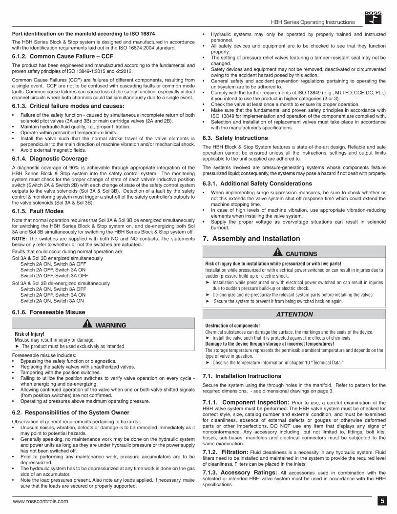
Port identification on the manifold according to ISO 16874
The HBH Series Block & Stop system is designed and manufactured in accordance with the identification requirements laid out in the ISO 16874:2004 standard.
6.1.2. Common Cause Failure – CCFThe product has been engineered and manufactured according to the fundamental and proven safety principles of ISO 13849-1:2015 and -2:2012.
Common Cause Failures (CCF) are failures of different components, resulting from a single event. CCF are not to be confused with cascading faults or common mode faults. Common cause failures can cause loss of the safety function, especially in dual channel circuits where both channels could fail simultaneously due to a single event.
6.1.3. Critical failure modes and causes:• Failure of the safety function - caused by simultaneous incomplete return of both
solenoid pilot valves (3A and 3B) or main cartridge valves (2A and 2B).• Maintain hydraulic fluid quality, i.e., proper filtration.• Operate within prescribed temperature limits.• Install the valve such that the normal stroke travel of the valve elements is
perpendicular to the main direction of machine vibration and/or mechanical shock.• Avoid external magnetic fields.
6.1.4. Diagnostic CoverageA diagnostic coverage of 90% is achievable through appropriate integration of the HBH Series Block & Stop system into the safety control system. The monitoring system must check for the proper change of state of each valve’s inductive position switch (Switch 2A & Switch 2B) with each change of state of the safety control system outputs to the valve solenoids (Sol 3A & Sol 3B). Detection of a fault by the safety control & monitoring system must trigger a shut-off of the safety controller’s outputs to the valve solenoids (Sol 3A & Sol 3B).
6.1.5. Fault Modes Note that normal operation requires that Sol 3A & Sol 3B be energized simultaneously for switching the HBH Series Block & Stop system on, and de-energizing both Sol 3A and Sol 3B simultaneously for switching the HBH Series Block & Stop system off.NOTE: The switches are supplied with both NC and NO contacts. The statements below only refer to whether or not the switches are actuated. Faults that could occur during normal operation are:Sol 3A & Sol 3B energized simultaneously Switch 2A ON, Switch 3A OFF Switch 2A OFF, Switch 3A ON Switch 2A OFF, Switch 3A OFF
Sol 3A & Sol 3B de-energized simultaneously Switch 2A ON, Switch 3A OFF Switch 2A OFF, Switch 3A ON Switch 2A ON, Switch 3A ON
6.1.6. Foreseeable Misuse
WARNINGRisk of Injury!Misuse may result in injury or damage.
f The product must be used exclusively as intended.
Foreseeable misuse includes:• Bypassing the safety function or diagnostics.• Replacing the safety valves with unauthorized valves.• Tampering with the position switches. • Failing to utilize the position switches to verify valve operation on every cycle -
when energizing and de-energizing.• Allowing continued operation of the valve when one or both valve shifted signals
(from position switches) are not confirmed.• Operating at pressures above maximum operating pressure.
6.2. Responsibilities of the System OwnerObservation of general requirements pertaining to hazards:• Unusual noises, vibration, defects or damage is to be remedied immediately as it
may point to potential hazards. • Generally speaking, no maintenance work may be done on the hydraulic system
and power units as long as they are under hydraulic pressure or the power supply has not been switched off.
• Prior to performing any maintenance work, pressure accumulators are to be depressurized.
• The hydraulic system has to be depressurized at any time work is done on the gas side of an accumulator.
• Note the load pressures present. Also note any loads applied. If necessary, make sure that the loads are secured or properly supported.
• Hydraulic systems may only be operated by properly trained and instructed personnel.
• All safety devices and equipment are to be checked to see that they function properly.
• The setting of pressure relief valves featuring a tamper-resistant seal may not be changed.
• Safety devices and equipment may not be removed, deactivated or circumvented owing to the accident hazard posed by this action.
• General safety and accident prevention regulations pertaining to operating the unit/system are to be adhered to.
• Comply with the further requirements of ISO 13849 (e. g., MTTFD, CCF, DC, PLr,) if you intend to use the product in higher categories (2 or 3).
• Check the valve at least once a month to ensure its proper operation.• Make sure that the fundamental and proven safety principles in accordance with
ISO 13849 for implementation and operation of the component are complied with.• Selection and installation of replacement valves must take place in accordance
with the manufacturer’s specifications.
6.3. Safety InstructionsThe HBH Block & Stop System features a state-of-the-art design. Reliable and safe operation cannot be ensured unless all the instructions, settings and output limits applicable to the unit supplied are adhered to.
The systems involved are pressure-generating systems whose components feature pressurized liquid; consequently, the systems may pose a hazard if not dealt with properly.
6.3.1. Additional Safety Considerations • When implementing surge suppression measures, be sure to check whether or
not this extends the valve system shut off response time which could extend the machine stopping time.
• In case of high levels of machine vibration, use appropriate vibration-reducing elements when installing the valve system.
• Supply the proper voltage as overvoltage situations can result in solenoid burnout.
7. Assembly and Installation
CAUTIONSRisk of injury due to installation while pressurized or with live parts!Installation while pressurized or with electrical power switched on can result in injuries due to sudden pressure build-up or electric shock.
f Installation while pressurized or with electrical power switched on can result in injuries due to sudden pressure build-up or electric shock.
f De-energize and de-pressurize the relevant system parts before installing the valves. f Secure the system to prevent it from being switched back on again.
ATTENTION
Destruction of components!Chemical substances can damage the surface, the markings and the seals of the device.
f Install the valve such that it is protected against the effects of chemicals.Damage to the device through storage at incorrect temperatures!The storage temperature represents the permissible ambient temperature and depends on the type of valve in question.
f Observe the temperature information in chapter 10 “Technical Data.”
7.1. Installation InstructionsSecure the system using the through holes in the manifold. Refer to pattern for the required dimensions, - see dimensional drawings on page 3.
7.1.1. Component Inspection: Prior to use, a careful examination of the HBH valve system must be performed. The HBH valve system must be checked for correct style, size, catalog number and external condition, and must be examined for cleanliness, absence of external defects or gouges or otherwise deformed parts or other imperfections. DO NOT use any item that displays any signs of nonconformance. Any accessory including, but not limited to, fittings, bolt kits, hoses, sub-bases, manifolds and electrical connectors must be subjected to the same examination.
7.1.2. Filtration: Fluid cleanliness is a necessity in any hydraulic system. Fluid filters need to be installed and maintained in the system to provide the required level of cleanliness. Filters can be placed in the inlets.
7.1.3. Accessory Ratings: All accessories used in combination with the selected or intended HBH valve system must be used in accordance with the HBH specifications.
HBH Series Operating Instructions
6 www.rosscontrols.com
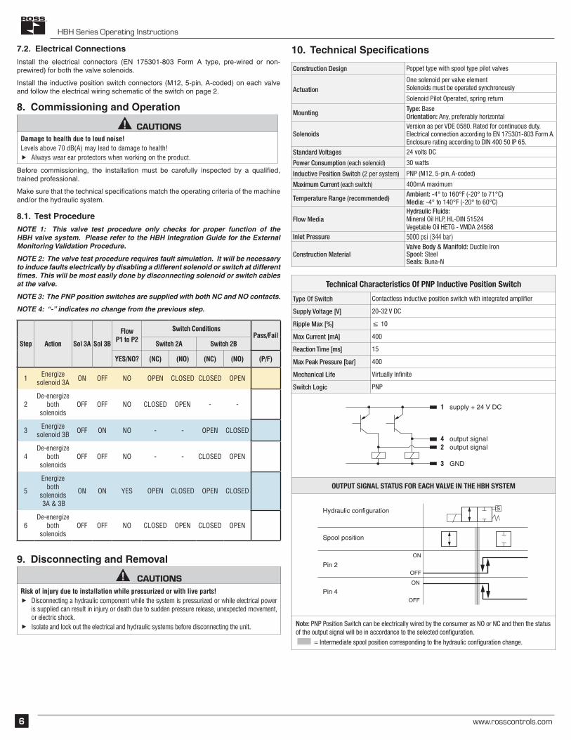
7.2. Electrical ConnectionsInstall the electrical connectors (EN 175301-803 Form A type, pre-wired or non-prewired) for both the valve solenoids.
Install the inductive position switch connectors (M12, 5-pin, A-coded) on each valve and follow the electrical wiring schematic of the switch on page 2.
8. Commissioning and Operation
CAUTIONSDamage to health due to loud noise!Levels above 70 dB(A) may lead to damage to health!
f Always wear ear protectors when working on the product.
Before commissioning, the installation must be carefully inspected by a qualified, trained professional.
Make sure that the technical specifications match the operating criteria of the machine and/or the hydraulic system.
8.1. Test ProcedureNOTE 1: This valve test procedure only checks for proper function of the HBH valve system. Please refer to the HBH Integration Guide for the External Monitoring Validation Procedure.
NOTE 2: The valve test procedure requires fault simulation. It will be necessary to induce faults electrically by disabling a different solenoid or switch at different times. This will be most easily done by disconnecting solenoid or switch cables at the valve.
NOTE 3: The PNP position switches are supplied with both NC and NO contacts.
NOTE 4: “-” indicates no change from the previous step.
Step Action Sol 3A Sol 3B
FlowP1 to P2
Switch ConditionsPass/Fail
Switch 2A Switch 2B
YES/NO? (NC) (NO) (NC) (NO) (P/F)
1 Energize solenoid 3A ON OFF NO OPEN CLOSED CLOSED OPEN
2De-energize
both solenoids
OFF OFF NO CLOSED OPEN - -
3 Energize solenoid 3B OFF ON NO - - OPEN CLOSED
4De-energize
both solenoids
OFF OFF NO - - CLOSED OPEN
5
Energize both
solenoids 3A & 3B
ON ON YES OPEN CLOSED OPEN CLOSED
6De-energize
both solenoids
OFF OFF NO CLOSED OPEN CLOSED OPEN
9. Disconnecting and Removal
CAUTIONSRisk of injury due to installation while pressurized or with live parts!
f Disconnecting a hydraulic component while the system is pressurized or while electrical power is supplied can result in injury or death due to sudden pressure release, unexpected movement, or electric shock.
f Isolate and lock out the electrical and hydraulic systems before disconnecting the unit.
10. Technical Specifications
Construction Design Poppet type with spool type pilot valves
ActuationOne solenoid per valve elementSolenoids must be operated synchronously
Solenoid Pilot Operated, spring return
MountingType: BaseOrientation: Any, preferably horizontal
SolenoidsVersion as per VDE 0580. Rated for continuous duty. Electrical connection according to EN 175301-803 Form A. Enclosure rating according to DIN 400 50 IP 65.
Standard Voltages 24 volts DC
Power Consumption (each solenoid) 30 watts
Inductive Position Switch (2 per system) PNP (M12, 5-pin, A-coded)
Maximum Current (each switch) 400mA maximum
Temperature Range (recommended)Ambient: -4° to 160°F (-20° to 71°C)Media: -4° to 140°F (-20° to 60°C)
Flow MediaHydraulic Fluids: Mineral Oil HLP, HL-DIN 51524 Vegetable Oil HETG - VMDA 24568
Inlet Pressure 5000 psi (344 bar)
Construction MaterialValve Body & Manifold: Ductile IronSpool: SteelSeals: Buna-N
Technical Characteristics Of PNP Inductive Position Switch
Type Of Switch Contactless inductive position switch with integrated amplifier
Supply Voltage [V] 20-32 V DC
Ripple Max [%] ≤ 10
Max Current [mA] 400
Reaction Time [ms] 15
Max Peak Pressure [bar] 400
Mechanical Life Virtually Infinite
Switch Logic PNP
1 supply + 24 V DC
4 output signal2 output signal
3 GND
OUTPUT SIGNAL STATUS FOR EACH VALVE IN THE HBH SYSTEM
Hydraulic configuration
ON
OFF
ON
OFF
Spool position
Pin 2
Pin 4
S
Note: PNP Position Switch can be electrically wired by the consumer as NO or NC and then the status of the output signal will be in accordance to the selected configuration.
= Intermediate spool position corresponding to the hydraulic configuration change.

HBH Series Operating Instructions
www.rosscontrols.com 7
STATUS OF OUTPUT SIGNAL
A: overlapping strokeB: damping stroke
According to the criteria of safety specifications, the poppet position signal must change state during the overlapping stroke (before the effective valve opening.)
WARNINGRisk of Injury!Misuse may result in injury or damage.
f The product must be used exclusively as intended.
1. Failure to observe the prescribed procedures and cautions may represent a risk for personal injury.
2. Safety valves must only be installed by qualified personnel.3. Safety valves must not be disassembled.4. The inductive position switches can only be adjusted by the valve manufacturer.5. Valve components cannot be interchanged.6. The valves must operate without switching shocks or spool vibration.7. There is a small portion of the main cartridge overlap stroke that may be undetectable and
may allow flow if the other main cartridge is in the open position. This could be as much as 15 gpm on size DIN 25 and 18 gpm on size DIN 32.
8. Check valves are used in the pilot supply system to ensure that the highest available pres-sure within the HBH system is supplied to the pilot valves. A failure of one of these check valves to close could allow as much as 10 gpm flow from P1 to P2, P2 to P1, or P2 to X (external pilot port).
9. It is recommended that a check valve be installed in the X (external pilot supply port) to help prevent flow from P2 to X when pressure in P2 is higher than the pressure in X.
11. DisposalDispose of the valve in accordance with the applicable statutory regulations in your country.
AmericAs
U.S.A.ROSS CONTROLS+1-248-764-1800sales@rosscontrols.comwww.rosscontrols.com
Customer Service 1-800-GET-ROSS (438-1800)Technical Service1-888-TEK-ROSS (835-7677)
Canada ROSS [email protected]
6077170 CANADA INC. An Independent RepResentatIve
BrazilROSS SOUTH AMERICA Ltda.+55-11-4335-2200vendas@rosscontrols.comwww.rosscontrols.com.br
europe
GermanyROSS EUROPA [email protected] www.rosseuropa.com
United KingdomROSS UK [email protected]
France ROSS FRANCE [email protected]
AsiA & pAcific
JapanROSS ASIA [email protected]
IndiaROSS CONTROLS INDIA Pvt. Ltd.+91-44-2624-9040sales.ri@rosscontrols.comwww.rosscontrols.com
ChinaROSS CONTROLS (CHINA) Ltd.+86-21-6915-79642sales.cn@rosscontrols.comwww.rosscontrolschina.com
United KingdomPNEUMATROL+44 (0)1254 [email protected]
U.S.A.AUTOMATIC VALVE+1-248-474-6700 [email protected].
ROSS DECCO+1-248-764-1800decco.sales@rosscontrols.comwww.rossdecco.com
GermanymanufactIS+49 (0)201 [email protected]
Printed in the U.S.A. – Rev. 04/23/20, © 2020 ROSS CONTROLS®. All Rights Reserved. Content subject to change. Form RC-HBH-OI
ROSS CONTROLS compAnies


![Stop' al dolor de cabeza - shcmedical.es · 'Stop' al dolor de cabeza Es tar] molesto que no le basra ur] solo ... b~a la ansiedad, que ilOS rek~jmnos y tam-biOn quc dormhnos ross](https://img.pdfslide.us/doc/110x75/5bba8be609d3f21e308b70e4/stop-al-dolor-de-cabeza-stop-al-dolor-de-cabeza-es-tar-molesto-que-no.jpg)