Embed Size (px)
Citation preview
Product Data Sheet00813-0100-4004, Rev BAMarch 2006 Rosemount 8800D
Rosemount 8800D Series Vortex Flowmeter
HART® AND FOUNDATION™ FIELDBUS PROTOCOLS• Available in wafer, flanged, dual, reducer and high pressure designs.
• Only manufacturer of Reducer™ Vortex which extends the measurable flow range, reduces installation costs, and minimizes project risk.
• All-welded, non-clog design eliminates ports and gaskets.
• Patented Adaptive Digital Signal Processing (ADSP) provides vibration immunity.
• Unique isolated sensor design allows replacement without breaking the process seal.
• Simplified troubleshooting through device diagnostics.
www.se
NOTEFOUND
ContentsSpecifications . . . . . . . . . . . . . . . . . . . . . . . . . . . . . . . . . . . . . . . . . . . . . . . . . . . . . . page 5
Product Certifications . . . . . . . . . . . . . . . . . . . . . . . . . . . . . . . . . . . . . . . . . . . . . . . page 18
Dimensional Drawings. . . . . . . . . . . . . . . . . . . . . . . . . . . . . . . . . . . . . . . . . . . . . . . page 21
Ordering Information . . . . . . . . . . . . . . . . . . . . . . . . . . . . . . . . . . . . . . . . . . . . . . . . page 35
Configuration Data Sheet . . . . . . . . . . . . . . . . . . . . . . . . . . . . . . . . . . . . . . . . . . . . page 39
rvinstrumentation.fr
ATION Fieldbus to be available late 2006.
Product Data Sheet00813-0100-4004, Rev BA
March 2006Rosemount 8800D
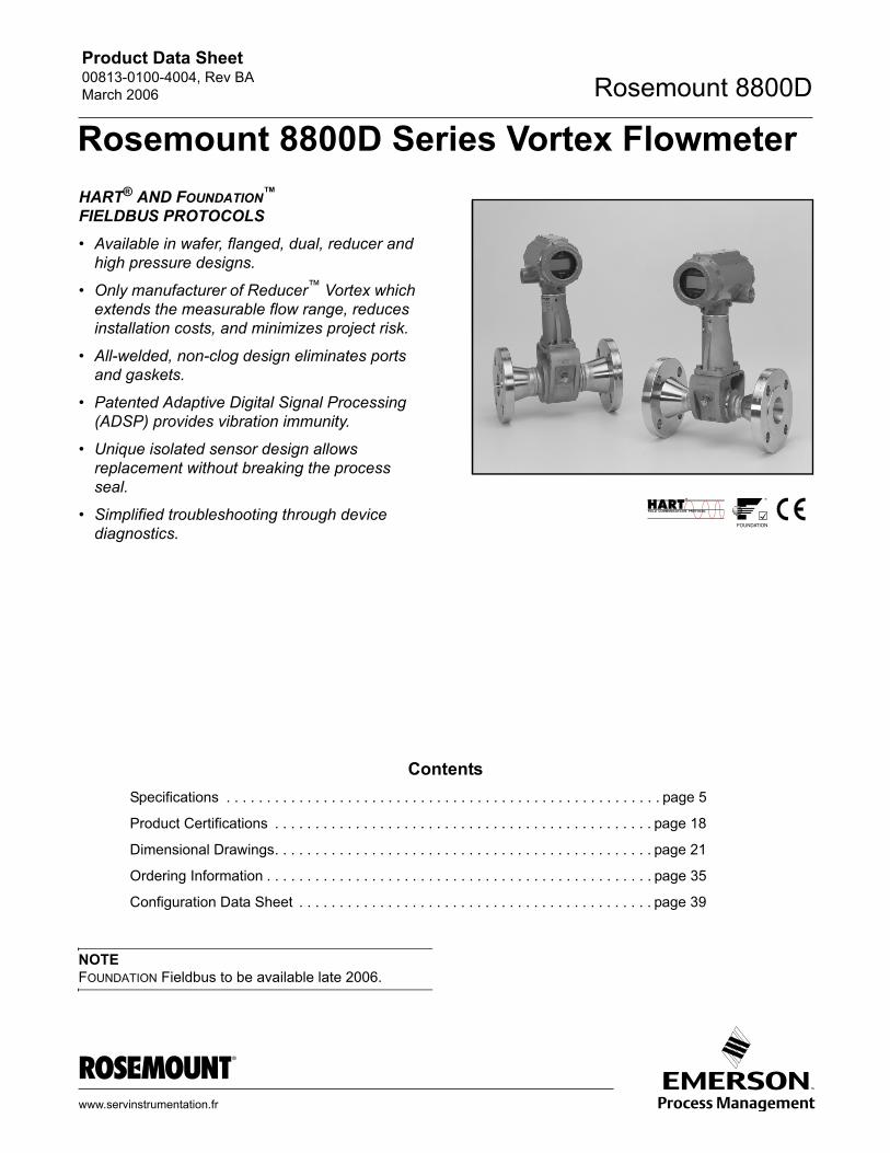
THE ROSEMOUNT 8800D DELIVERS RELIABILITY
• Rosemount Reliability -The 8800D Vortex eliminates impulse lines, ports, and gaskets to improve reliability.
• Non-clog Design - Unique gasket-free construction which has no ports that can clog.
• Vibration Immunity - Mass Balancing of the sensor system, and Patented Adaptive Digital Signal Processing (ADSP) provide Vibration immunity.
• Replaceable Sensor - The sensor is isolated from the process and can be replaced without breaking the process seals. All line sizes use the same sensor design allowing a single spare to serve every meter.
• Simplified Troubleshooting - Device Diagnostics enable field verification of Meter Electronics and Sensor with no process shutdown.
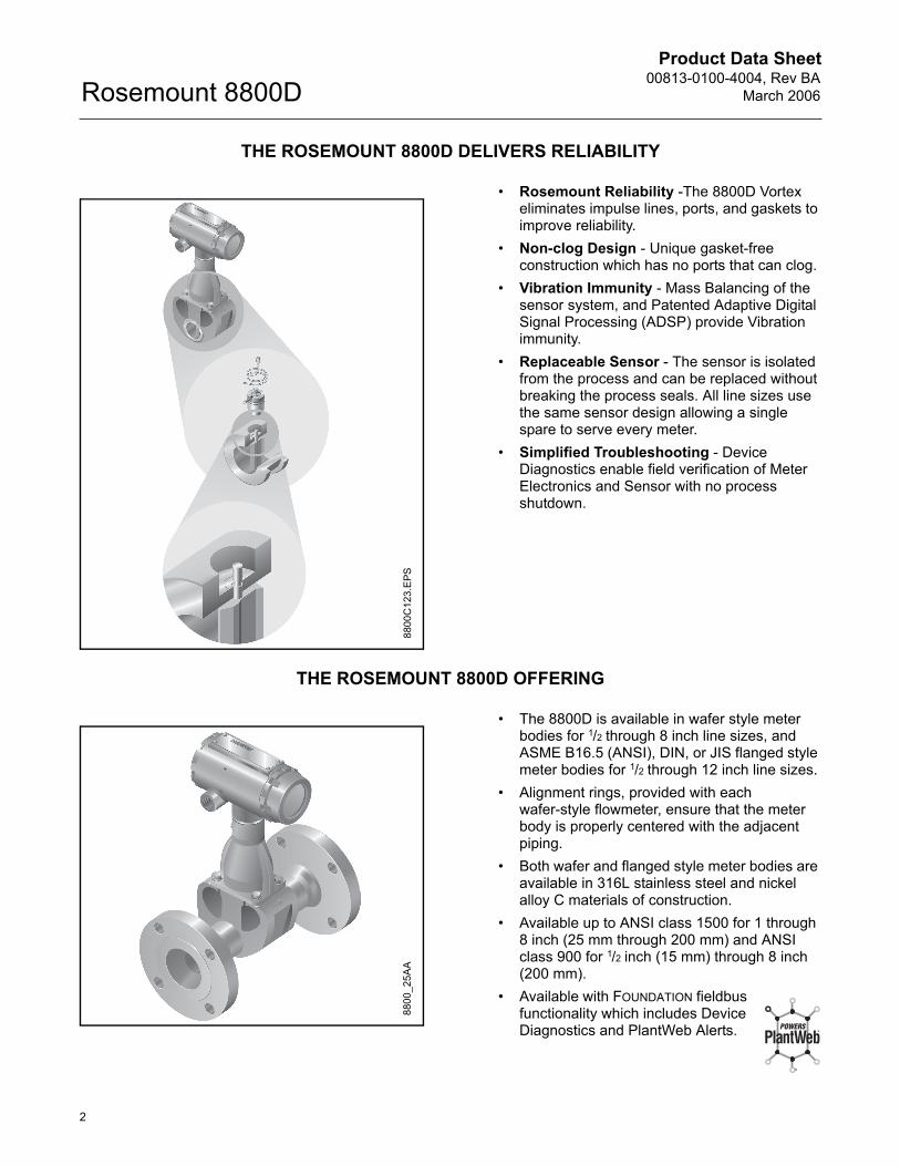
THE ROSEMOUNT 8800D OFFERING
• The 8800D is available in wafer style meter bodies for 1/2 through 8 inch line sizes, and ASME B16.5 (ANSI), DIN, or JIS flanged style meter bodies for 1/2 through 12 inch line sizes.
• Alignment rings, provided with each wafer-style flowmeter, ensure that the meter body is properly centered with the adjacent piping.
• Both wafer and flanged style meter bodies are available in 316L stainless steel and nickel alloy C materials of construction.
• Available up to ANSI class 1500 for 1 through 8 inch (25 mm through 200 mm) and ANSI class 900 for 1/2 inch (15 mm) through 8 inch (200 mm).
• Available with FOUNDATION fieldbus functionality which includes Device Diagnostics and PlantWeb Alerts.
8800
C12
3.EP
S88
00_2
5AA
2
Product Data Sheet00813-0100-4004, Rev BAMarch 2006 Rosemount 8800D
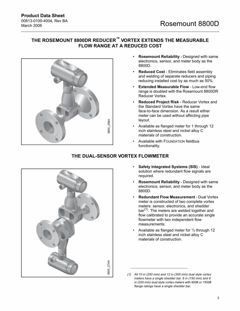
THE ROSEMOUNT 8800DR REDUCER™ VORTEX EXTENDS THE MEASURABLE FLOW RANGE AT A REDUCED COST
• Rosemount Reliability - Designed with same electronics, sensor, and meter body as the 8800D.
• Reduced Cost - Eliminates field assembly and welding of separate reducers and piping reducing installed cost by as much as 50%.
• Extended Measurable Flow - Low-end flow range is doubled with the Rosemount 8800DR Reducer Vortex.
• Reduced Project Risk - Reducer Vortex and the Standard Vortex have the same face-to-face dimension. As a result either meter can be used without affecting pipe layout.
• Available as flanged meter for 1 through 12 inch stainless steel and nickel alloy C materials of construction.
• Available with FOUNDATION fieldbus functionality.
THE DUAL-SENSOR VORTEX FLOWMETER
• Safety Integrated Systems (SIS) - Ideal solution where redundant flow signals are required.
• Rosemount Reliability - Designed with same electronics, sensor, and meter body as the 8800D.
• Redundant Flow Measurement - Dual Vortex meter is constructed of two complete vortex meters: sensor, electronics, and shedder bar(1). The meters are welded together and flow calibrated to provide an accurate single flowmeter with two independent flow measurements.
• Available as flanged meter for 1/2 through 12 inch stainless steel and nickel alloy C materials of construction.
8800
_25B
A88
00_2
7AA
(1) All 10 in (250 mm) and 12 in (300 mm) dual style vortex meters have a single shedder bar. 6 in (150 mm) and 8 in (200 mm) dual style vortex meters with 900# or 1500# flange ratings have a single shedder bar.
3
Product Data Sheet00813-0100-4004, Rev BA
March 2006Rosemount 8800D
ROSEMOUNT 8800D VORTEX FLOWMETER WITH FOUNDATION FIELDBUSThe software for the 8800D Flowmeter with FOUNDATION fieldbus permits remote testing and configuration using any FOUNDATION fieldbus-compliant host, such as the DeltaV system from Emerson Process Management.
Transducer BlockThe transducer block calculates flow from sensor frequency. The calculation includes information about damping, shedding frequency, K-factor, service type, pipe ID, and diagnostics.
Resource BlockThe resource block contains physical transmitter information, including available memory, manufacturer identification, device type, software tag, and unique identification.
Backup Link Active Scheduler (LAS)The transmitter is classified as a device link master. A device link master can function as a Link Active Scheduler (LAS) if the current link master device fails or is removed from the segment.
The host or other configuration tool is used to download the schedule for the application to the link master device. In the absence of a primary link master, the transmitter will claim the LAS and provide permanent control for the H1 segment.
DiagnosticsThe transmitter automatically performs continuous self-diagnostics. The user can perform on-line testing of the transmitter digital signal. Advanced simulation diagnostics are available. This enables remote verification of the electronics via a flow signal generator built into the electronics. The sensor strength value can be used to view the process flow signal and provide information regarding filter settings.
FOUNDATION Fieldbus Function BlocksAnalog Input
The AI function block processes the measurement and makes it available to other function blocks. The AI function block also allows filtering, alarming, and engineering unit changes.
The 8800D Flowmeter with FOUNDATION fieldbus comes standard with two AI function blocks.
Proportional/Integral/Derivative
The optional PID function block provides a sophisticated implementation of the universal PID algorithm. The PID function block features input for feed forward control, alarms on the process variable, and control deviation. The PID type (series or Instrument Society of America [ISA]) is user-selectable on the derivative filter.
IntegratorThe standard integrator block is available for totalization of flow.
SetupBasic setup requires connecting the transmitter to a fieldbus network or 375 Handheld Communicator. The FOUNDATION fieldbus- compliant host will automatically establish communication with the device.
The Rosemount 8800D Flowmeter can be easily configured using the DeltaV system. User-configurable parameters include: tag, range values and units, service type, damping, process density, pipe inside diameter (ID)(1), and process temperature(1).
Tagging information can be entered into the transmitter to allow identification and a physical description. 32-character tags are provided for identification of the transmitter and each function block.
(1) Process temperature and pipe ID have known effects on the K-factor. The 8800D software automatically accounts for these effects by compensating the K-factor.
4
Product Data Sheet00813-0100-4004, Rev BAMarch 2006 Rosemount 8800D
Specifications
The following specifications are for the Rosemount 8800D, Rosemount 8800DR, and Rosemount 8800DD, except where noted.
FUNCTIONAL SPECIFICATIONS
ServiceLiquid, gas, and steam applications. Fluids must be homogeneous and single-phase.
Line Sizes
Wafer1/2, 1, 11/2, 2, 3, 4, 6, and 8 inches(DN 15, 25, 40, 50, 80, 100, 150, and 200)
Flanged and Dual-Sensor Style1/2, 1, 11/2, 2, 3, 4, 6, 8, 10, and 12 inches(DN 15, 25, 40, 50, 80, 100, 150, 200, 250, and 300)
Reducer1, 11/2, 2, 3, 4, 6, 8, 10, and 12 inches(DN 25, 40, 50, 80, 100, 150, 200, 250, and 300)
Pipe SchedulesProcess piping Schedules 10, 40, 80, and 160.
NOTEThe appropriate bore diameter of the process piping must be entered using the HART Communicator or AMS. Meters will be shipped from the factory at the Schedule 40 default value unless otherwise specified.
Measurable Flow RatesCapable of processing signals from flow applications which meet the sizing requirements below. To determine the appropriate flowmeter size for an application, process conditions must be within the Reynolds number and velocity limitations for the desired line size provided in Table 1, Table 2, Table 3, and Table 4.
NOTEConsult your local sales representative to obtain a computer sizing program that describes in greater detail how to specify the correct flowmeter size for an application.
The Reynolds number equation shown below combines the effects of density (�), viscosity (�cp), pipe inside diameter (D), and flow velocity (V).
Process Temperature Limits
Standard–40 to 450 °F (–40 to 232 °C)
Extended–330 to 800 °F (–200 to 427 °C)
RDVDρμcp------------=
TABLE 1. Minimum Measurable Meter Reynolds NumbersMeter Sizes
(Inches / DN) Reynolds Number Limitations1/2 through 4/15 through 100 10000 minimum
6 through 12/150 through 300 20000 minimum
TABLE 2. Minimum Measurable Meter Velocities(1)
(Use the larger of the two values)
(1) Velocities are referenced to schedule 40 pipe.
Feet per Second Meters per SecondLiquids(2)
(2) The minimum measurable velocity for the 10in. line size is 0.94 ft/s (.29m/s) and 1.11 ft/s (.34m/s) for the 12in. line size.
GasesThe ρ is the process fluid density at flowing conditions in lb/ft3 for ft/s and kg/m3 for m/s
TABLE 3. Maximum Measurable Meter Velocities(1)
(Use the smaller of the two values)
(1) Velocities are referenced to schedule 40 pipe.
Feet per Second Meters per Second
LiquidsGases(2)
(2) Accuracy limitations for gas and steam for Dual-style meters (1/2” to 8”): max velocity of 100 ft/s (30.5 m/s).
The ρ is the process fluid density at flowing conditions in lb/ft3 for ft/s and kg/m3 for m/s
36/ρ or 0.7 54/ρ or 0.2236/ρ or 6.5 54/ρ or 2.0
90,000/ρ or 25 134,000/ρ or 7.690,000/ρ or 250 134,000/ρ or 76
5
Product Data Sheet00813-0100-4004, Rev BA
March 2006Rosemount 8800D
Output Signals
4–20 mA Digital HART Signal Superimposed on 4–20 mA signal
Optional Scalable Pulse Output0 to 10000 Hz; transistor switch closure with adjustable scaling via HART communications; capable of switching up to 30 V dc, 120 mA maximum
Digital Foundation fieldbus signal Manchester-encoded digital signal that conforms to IEC 1158-2 and ISA 50.02.
Analog Output AdjustmentEngineering units and lower and upper range values are user-selected. Output is automatically scaled to provide 4 mA at the selected lower range value, 20 mA at the selected upper range value. No frequency input is required to adjust the range values.
Scalable Frequency AdjustmentThe scalable pulse output can be set to a specific velocity, volume, or mass (i.e. 1 pulse = 1 lb). The scalable pulse output can also be scaled to a specific rate of volume, mass, or velocity (i.e. 100 Hz = 500 lb/hr).
Ambient Temperature Limits
Operating–58 to 185 °F (–50 to 85 °C)–4 to 185 °F (–20 to 85 °C) for flowmeters with local indicator
Storage –58 to 250 °F (–50 to 121 °C)–50 to 185 °F (–46 to 85 °C) for flowmeters with local indicator
Pressure Limits
Flange Style Meter Rated for ASME B16.5 (ANSI) Class 150, 300, 600, 900, and 1500, DIN PN 10, 16, 25, 40, 64, 100, and 160, and JIS 10K, 20K, and 40K
Reducer Style Meter Rated for ASME B16.5 (ANSI) Class 150, 300, 600, and 900, DIN PN 10, 16, 25, 40, 64, 100, and 160.
Dual Sensor Style MeterRated for ASME B16.5 (ANSI) Class 150, 300, 600, 900, and 1500, DIN PN 10, 16, 25, 40, 64, 100, and 160, and JIS 10K, 20K, and 40K
Wafer Style Meter Rated for ASME B16.5 (ANSI) Class 150, 300, and 600, DIN PN 10, 16, 25, 40, 64, and 100, and JIS 10K, 20K, and 40K
Power Supply
HART AnalogExternal power supply required. Flowmeter operates on 10.8 to 42 V dc terminal voltage (with 250-ohm minimum load required for HART communications, 16.8 V dc power supply is required)
Foundation fieldbusExternal power supply required. Flowmeter operates on 9 to 32 V dc, 17.8 mA nominal, 20.0 mA maximum.
Power ConsumptionOne watt maximum
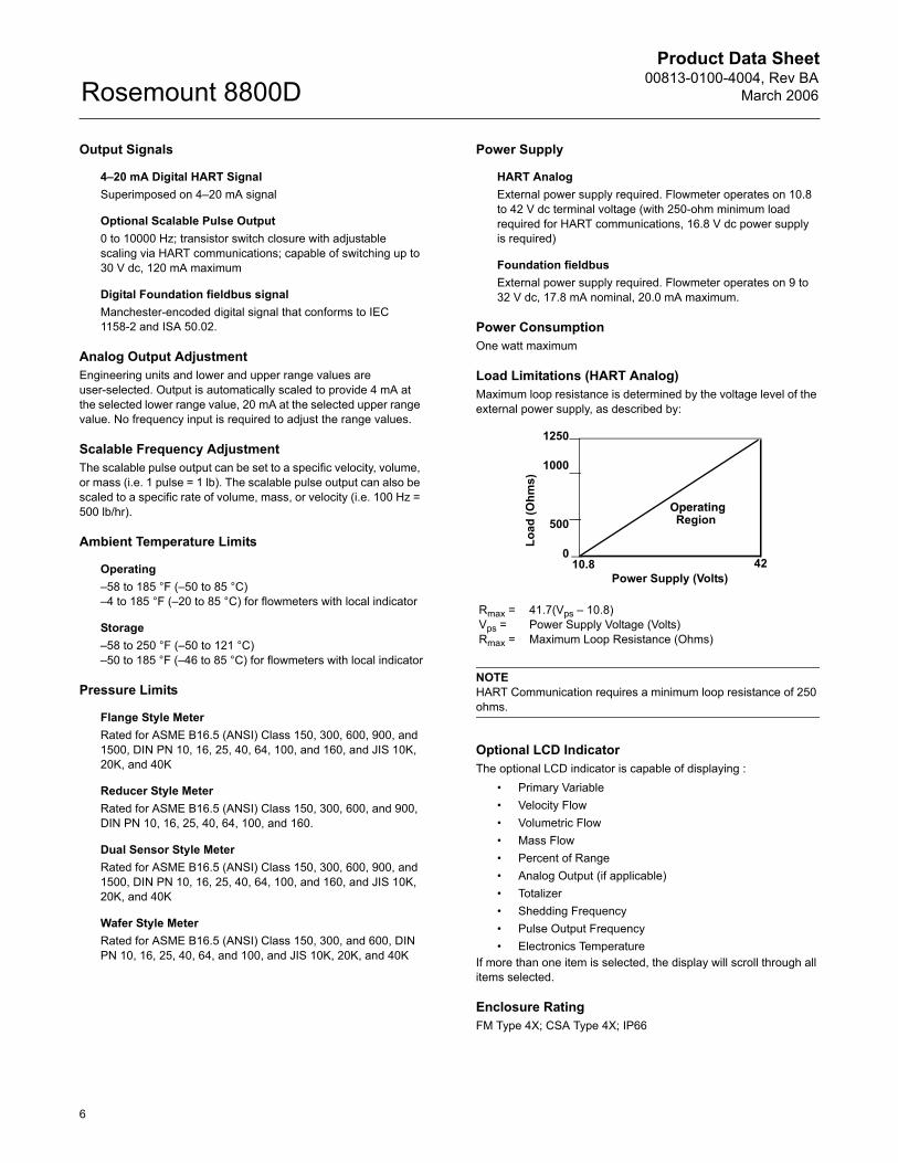
Load Limitations (HART Analog)Maximum loop resistance is determined by the voltage level of the external power supply, as described by:
NOTEHART Communication requires a minimum loop resistance of 250 ohms.
Optional LCD IndicatorThe optional LCD indicator is capable of displaying :
• Primary Variable• Velocity Flow• Volumetric Flow• Mass Flow• Percent of Range• Analog Output (if applicable)• Totalizer• Shedding Frequency• Pulse Output Frequency• Electronics Temperature
If more than one item is selected, the display will scroll through all items selected.
Enclosure RatingFM Type 4X; CSA Type 4X; IP66
Rmax = 41.7(Vps – 10.8)Vps = Power Supply Voltage (Volts)Rmax = Maximum Loop Resistance (Ohms)
Power Supply (Volts)
Load
(Ohm
s)
OperatingRegion
1250
1000
500
010.8 42
6
Product Data Sheet00813-0100-4004, Rev BAMarch 2006 Rosemount 8800D
Permanent Pressure LossThe approximate permanent pressure loss (PPL) from the Rosemount 8800D flowmeter is calculated for each application in the Vortex sizing software available from your local Rosemount representative. The PPL is determined using the equation:
where:
Minimum Back Pressure (Liquids)Flow metering conditions that would allow cavitation, the release of vapor from a liquid, should be avoided. This flow condition can be avoided by remaining within the proper flow range of the meter and by following appropriate system design. For some liquid applications, incorporation of a back pressure valve should be considered. To prevent cavitation, the minimum back pressure should be:
Failure Mode Alarm
HART AnalogIf self-diagnostics detect a gross flowmeter failure, the analog signal will be driven to the values below:
High or low alarm signal is user-selectable through the fail mode alarm jumper on the electronics. NAMUR-compliant alarm limits are available through the C4 or CN Option. Alarm type is field configurable also.
Foundation fieldbusThe AI block allows the user to configure the alarm to HI-HI, HI, LO, or LO-LO with a variety of priority levels.
Saturation Output ValuesWhen the operating flow is outside the range points, the analog output continues to track the operating flow until reaching the saturation value listed below; the output does not exceed the listed saturation value regardless of the operating flow. The NAMUR-Compliant Saturation Values are available through the C4 or CN option. Saturation type is field configurable..
DampingAdjustable between 0.2 and 255 seconds.
Response TimeThree vortex shedding cycles or 300 ms, whichever is greater, maximum required to reach 63.2% of actual input with the minimum damping (0.2 seconds).
Turn-on Time
HART AnalogLess than four (4) seconds plus the response time to rated accuracy from power up.
Foundation fieldbusPerformance within specifications no greater than 10.0 seconds after power is applied.
PPL = Permanent Pressure loss (psi or kPa)
where:�f = Density at operating conditions (lb/ft3 or kg/m3)
Q = Actual volumetric flow rate (Gas = ft3/min or m3/hr; Liquid = gal/min or l/min)
D = Flowmeter bore diameter (in. or mm)
A = Constant depending on meter style, fluid type and flow units. Determined per following table:
TABLE 4. Determining the PPL
Meter Style
English Units SI Units
ALiquid AGas ALiquid AGas
8800DF/W 3.4 � 10-5 1.9 � 10-3 0.425 1188800DR 3.91 � 10-5 2.19 � 10-3 0.489 136
8800DD(1)
(1) For all 10 and 12 in (250 and 300 mm) line sizes and 6 and 8 in (150 and 200 mm) with 900# or 1500# Flanges, A for Rosemount 8800DD is the same as Rosemount 8800DF.
6.12 � 10-5 3.42 � 10-3 0.765 212
P = 2.9∗ΔP + 1.3∗pv or P = 2.9∗ΔP + pv + 0.5 psia (3.45 kPa) (use the smaller of the two results)
P = Line pressure five pipe diameters downstream of the meter (psia or kPa abs)
ΔP= Pressure loss across the meter (psi or kPa)pv = Liquid vapor pressure at operating conditions (psia or kPa
abs)
PPLA ρ f× Q2×
D4--------------------------------=
Low 3.75High 22.6NAMUR Low 3.60NAMUR High 22.6
Low 3.9High 20.8NAMUR Low 3.8NAMUR High 20.5
7
Product Data Sheet00813-0100-4004, Rev BA
March 2006Rosemount 8800D
Transient ProtectionThe optional transient terminal block prevents damage to the flowmeter from transients induced by lightning, welding, heavy electrical equipment, or switch gears. The transient protection electronics are located in the terminal block.
The transient terminal block meets the following specifications:ASME B16.5 (ANSI)/IEEE C62.41 - 1980 (IEEE 587) Categories A, B 3 kA crest (8 � 20 μs)6 kV crest (1.2 � 50 μs)6 kV/0.5 kA (0.5 μs, 100 kHz, ring wave)
Security LockoutWhen the security lockout jumper is enabled, the electronics will not allow you to modify parameters that affect flowmeter output.
Output Testing
Current SourceFlowmeter may be commanded to set the current to a specified value between 4 and 20 mA.
Frequency SourceFlowmeter may be commanded to set the frequency to a specified value between 0 and 10000 Hz.
Low Flow CutoffAdjustable over entire flow range. Below selected value, output is driven to 4 mA and zero pulse output frequency (in the scaled pulse mode only).
Humidity LimitsOperates in 0–95% relative humidity under noncondensing conditions (tested to IEC 60770, Section 6.2.11).
Overrange Capability
HART AnalogAnalog signal output continues to 105 percent of span, then remains constant with increasing flow. The digital and pulse outputs will continue to indicate flow up to the upper sensor limit of the flowmeter and a maximum pulse output frequency of 10400 Hz.
Foundation fieldbusFor liquid service type, the transducer block digital output will continue to a nominal value of 25 ft/s. After that, the status associated with the transducer block output will go to UNCERTAIN. Above a nominal value of 30 ft/s, the status will go to BAD. For gas/steam service, the transducer block digital output will continue to a nominal value of 220 ft/s for 0.5 and 1.0 in. line sizes and a nominal value of 250 ft/s for 1.5–12 in. line sizes. After that, the status associated with the transducer block output will go to UNCERTAIN. Above a nominal value of 300 ft/s for all line sizes, the status will go to BAD.
Flow CalibrationMeter bodies are flow-calibrated and assigned a unique calibration factor (K-factor) at the factory. The calibration factor is entered into the electronics, enabling interchangeability of electronics and/or sensors without calculations or compromise in accuracy of the calibrated meter body.
Status (FOUNDATION fieldbus only)If self-diagnostics detect a transmitter failure, the status of the measurement will inform the control system. Status may also set the PID output to a safe value.
Schedule Entries (FOUNDATION fieldbus only)Six (6)
Links (FOUNDATION fieldbus only)Twelve (12)
Virtual Communications Relationships (VCRs) (FOUNDATION fieldbus only)Two (2) predefined (F6, F7)Four (4) configured (see Table 5)
TABLE 5. Block Information.
Block Base IndexExecution Time (Milliseconds)
Resource (RB) 300 —Transducer (TB) 400 —Analog Input (AI) 1,000 15
Proportional/Integral/Derivative (PID)
10,000 25
Integrator (INT) 12,000 20
8
Product Data Sheet00813-0100-4004, Rev BAMarch 2006 Rosemount 8800D
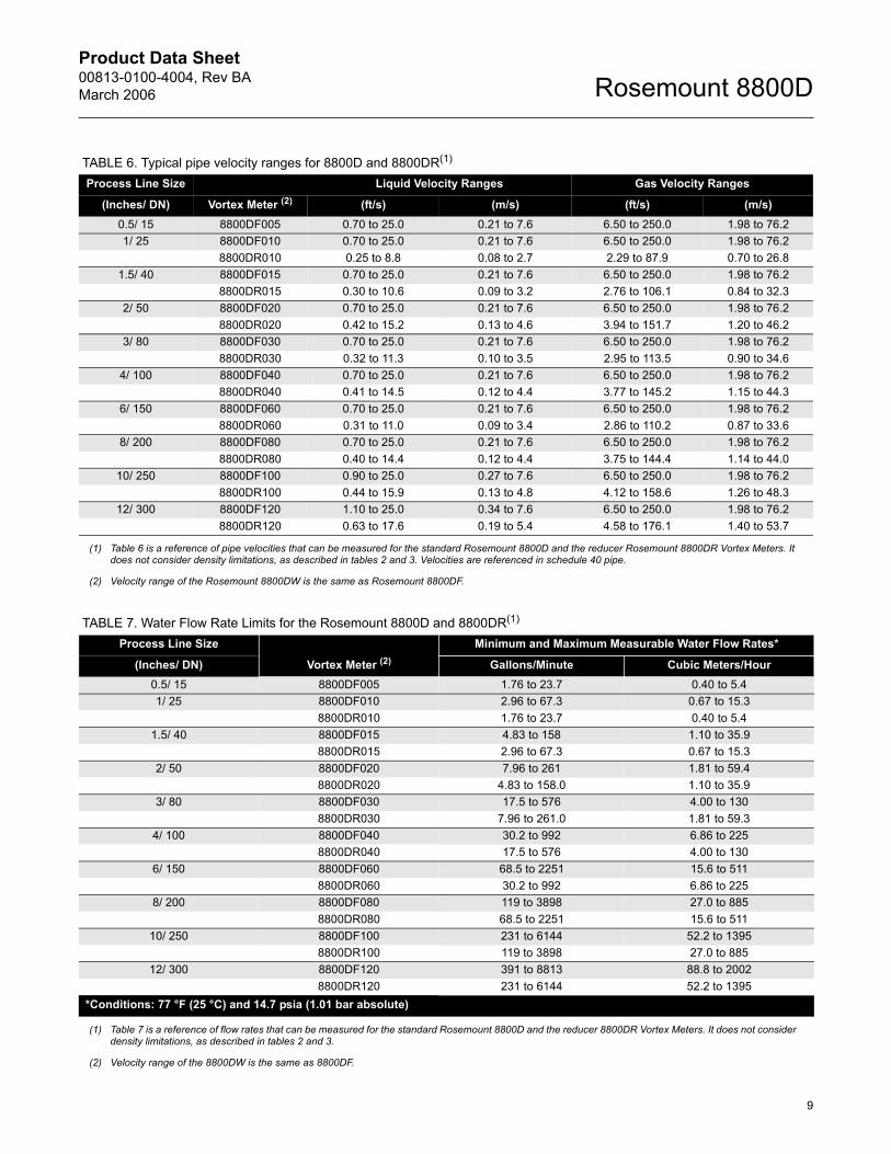
TABLE 6. Typical pipe velocity ranges for 8800D and 8800DR(1)
Process Line Size Liquid Velocity Ranges Gas Velocity Ranges
(Inches/ DN) Vortex Meter (2) (ft/s) (m/s) (ft/s) (m/s)0.5/ 15 8800DF005 0.70 to 25.0 0.21 to 7.6 6.50 to 250.0 1.98 to 76.21/ 25 8800DF010 0.70 to 25.0 0.21 to 7.6 6.50 to 250.0 1.98 to 76.2
8800DR010 0.25 to 8.8 0.08 to 2.7 2.29 to 87.9 0.70 to 26.81.5/ 40 8800DF015 0.70 to 25.0 0.21 to 7.6 6.50 to 250.0 1.98 to 76.2
8800DR015 0.30 to 10.6 0.09 to 3.2 2.76 to 106.1 0.84 to 32.32/ 50 8800DF020 0.70 to 25.0 0.21 to 7.6 6.50 to 250.0 1.98 to 76.2
8800DR020 0.42 to 15.2 0.13 to 4.6 3.94 to 151.7 1.20 to 46.23/ 80 8800DF030 0.70 to 25.0 0.21 to 7.6 6.50 to 250.0 1.98 to 76.2
8800DR030 0.32 to 11.3 0.10 to 3.5 2.95 to 113.5 0.90 to 34.64/ 100 8800DF040 0.70 to 25.0 0.21 to 7.6 6.50 to 250.0 1.98 to 76.2
8800DR040 0.41 to 14.5 0.12 to 4.4 3.77 to 145.2 1.15 to 44.36/ 150 8800DF060 0.70 to 25.0 0.21 to 7.6 6.50 to 250.0 1.98 to 76.2
8800DR060 0.31 to 11.0 0.09 to 3.4 2.86 to 110.2 0.87 to 33.68/ 200 8800DF080 0.70 to 25.0 0.21 to 7.6 6.50 to 250.0 1.98 to 76.2
8800DR080 0.40 to 14.4 0.12 to 4.4 3.75 to 144.4 1.14 to 44.010/ 250 8800DF100 0.90 to 25.0 0.27 to 7.6 6.50 to 250.0 1.98 to 76.2
8800DR100 0.44 to 15.9 0.13 to 4.8 4.12 to 158.6 1.26 to 48.312/ 300 8800DF120 1.10 to 25.0 0.34 to 7.6 6.50 to 250.0 1.98 to 76.2
8800DR120 0.63 to 17.6 0.19 to 5.4 4.58 to 176.1 1.40 to 53.7
(1) Table 6 is a reference of pipe velocities that can be measured for the standard Rosemount 8800D and the reducer Rosemount 8800DR Vortex Meters. It does not consider density limitations, as described in tables 2 and 3. Velocities are referenced in schedule 40 pipe.
(2) Velocity range of the Rosemount 8800DW is the same as Rosemount 8800DF.
TABLE 7. Water Flow Rate Limits for the Rosemount 8800D and 8800DR(1)
Process Line Size
Vortex Meter (2)
Minimum and Maximum Measurable Water Flow Rates*
(Inches/ DN) Gallons/Minute Cubic Meters/Hour0.5/ 15 8800DF005 1.76 to 23.7 0.40 to 5.41/ 25 8800DF010 2.96 to 67.3 0.67 to 15.3
8800DR010 1.76 to 23.7 0.40 to 5.41.5/ 40 8800DF015 4.83 to 158 1.10 to 35.9
8800DR015 2.96 to 67.3 0.67 to 15.32/ 50 8800DF020 7.96 to 261 1.81 to 59.4
8800DR020 4.83 to 158.0 1.10 to 35.93/ 80 8800DF030 17.5 to 576 4.00 to 130
8800DR030 7.96 to 261.0 1.81 to 59.34/ 100 8800DF040 30.2 to 992 6.86 to 225
8800DR040 17.5 to 576 4.00 to 1306/ 150 8800DF060 68.5 to 2251 15.6 to 511
8800DR060 30.2 to 992 6.86 to 2258/ 200 8800DF080 119 to 3898 27.0 to 885
8800DR080 68.5 to 2251 15.6 to 51110/ 250 8800DF100 231 to 6144 52.2 to 1395
8800DR100 119 to 3898 27.0 to 88512/ 300 8800DF120 391 to 8813 88.8 to 2002
8800DR120 231 to 6144 52.2 to 1395*Conditions: 77 °F (25 °C) and 14.7 psia (1.01 bar absolute)
(1) Table 7 is a reference of flow rates that can be measured for the standard Rosemount 8800D and the reducer 8800DR Vortex Meters. It does not consider density limitations, as described in tables 2 and 3.
(2) Velocity range of the 8800DW is the same as 8800DF.
9
Product Data Sheet00813-0100-4004, Rev BA
March 2006Rosemount 8800D
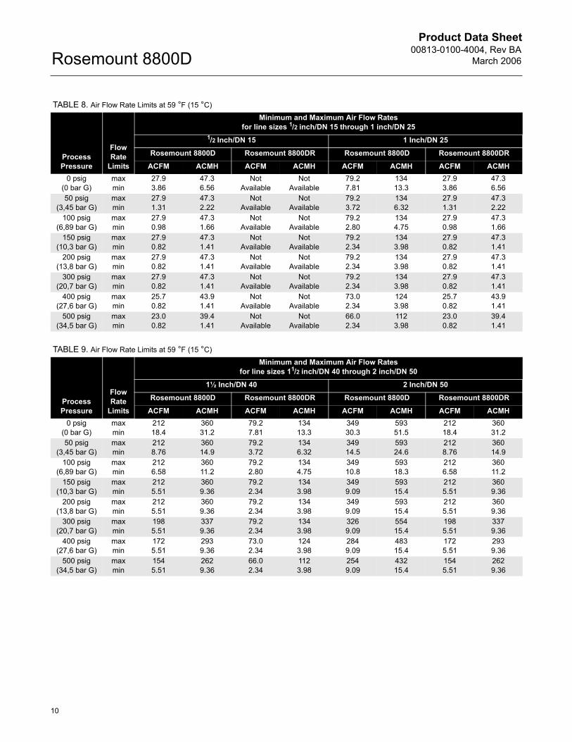
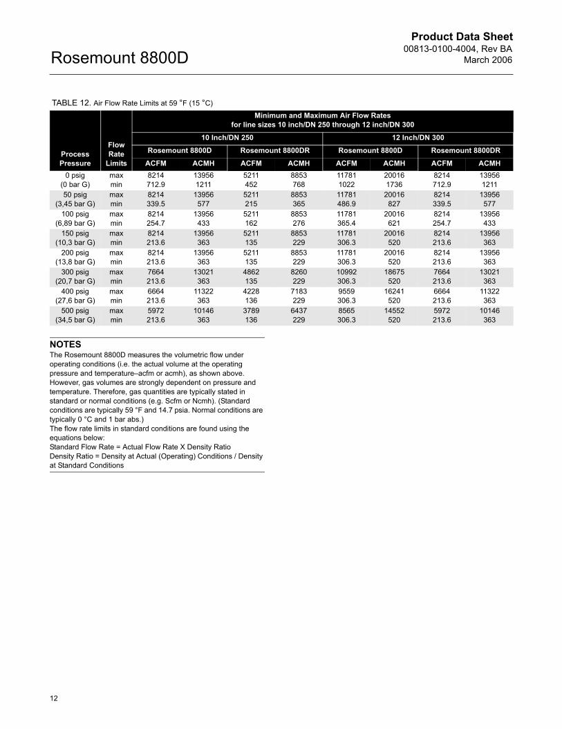
TABLE 8. Air Flow Rate Limits at 59 °F (15 °C)
Process Pressure
Flow Rate
Limits
Minimum and Maximum Air Flow Ratesfor line sizes 1/2 inch/DN 15 through 1 inch/DN 25
1/2 Inch/DN 15 1 Inch/DN 25
Rosemount 8800D Rosemount 8800DR Rosemount 8800D Rosemount 8800DR
ACFM ACMH ACFM ACMH ACFM ACMH ACFM ACMH0 psig
(0 bar G)maxmin
27.93.86
47.36.56
Not Available
Not Available
79.27.81
13413.3
27.93.86
47.36.56
50 psig(3,45 bar G)
maxmin
27.91.31
47.32.22
Not Available
Not Available
79.23.72
1346.32
27.91.31
47.32.22
100 psig(6,89 bar G)
maxmin
27.90.98
47.31.66
Not Available
Not Available
79.22.80
1344.75
27.90.98
47.31.66
150 psig(10,3 bar G)
maxmin
27.90.82
47.31.41
Not Available
Not Available
79.22.34
1343.98
27.90.82
47.31.41
200 psig(13,8 bar G)
maxmin
27.90.82
47.31.41
Not Available
Not Available
79.22.34
1343.98
27.90.82
47.31.41
300 psig(20,7 bar G)
maxmin
27.90.82
47.31.41
Not Available
Not Available
79.22.34
1343.98
27.90.82
47.31.41
400 psig(27,6 bar G)
maxmin
25.70.82
43.91.41
Not Available
Not Available
73.02.34
1243.98
25.70.82
43.91.41
500 psig(34,5 bar G)
maxmin
23.00.82
39.41.41
Not Available
Not Available
66.02.34
1123.98
23.00.82
39.41.41
TABLE 9. Air Flow Rate Limits at 59 °F (15 °C)
Process Pressure
Flow Rate
Limits
Minimum and Maximum Air Flow Ratesfor line sizes 11/2 inch/DN 40 through 2 inch/DN 50
1½ Inch/DN 40 2 Inch/DN 50
Rosemount 8800D Rosemount 8800DR Rosemount 8800D Rosemount 8800DR
ACFM ACMH ACFM ACMH ACFM ACMH ACFM ACMH0 psig
(0 bar G)maxmin
21218.4
36031.2
79.27.81
13413.3
34930.3
59351.5
21218.4
36031.2
50 psig(3,45 bar G)
maxmin
2128.76
36014.9
79.23.72
1346.32
34914.5
59324.6
2128.76
36014.9
100 psig(6,89 bar G)
maxmin
2126.58
36011.2
79.22.80
1344.75
34910.8
59318.3
2126.58
36011.2
150 psig(10,3 bar G)
maxmin
2125.51
3609.36
79.22.34
1343.98
3499.09
59315.4
2125.51
3609.36
200 psig(13,8 bar G)
maxmin
2125.51
3609.36
79.22.34
1343.98
3499.09
59315.4
2125.51
3609.36
300 psig(20,7 bar G)
maxmin
1985.51
3379.36
79.22.34
1343.98
3269.09
55415.4
1985.51
3379.36
400 psig(27,6 bar G)
maxmin
1725.51
2939.36
73.02.34
1243.98
2849.09
48315.4
1725.51
2939.36
500 psig(34,5 bar G)
maxmin
1545.51
2629.36
66.02.34
1123.98
2549.09
43215.4
1545.51
2629.36
10
Product Data Sheet00813-0100-4004, Rev BAMarch 2006 Rosemount 8800D
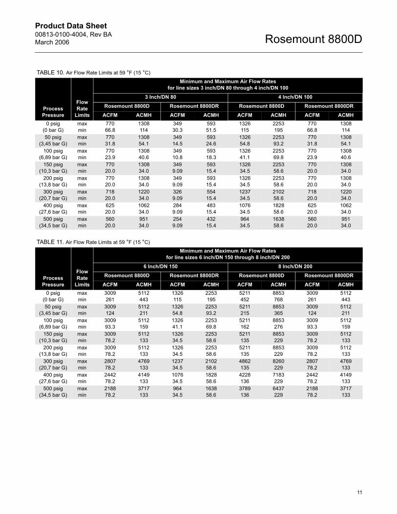
TABLE 10. Air Flow Rate Limits at 59 °F (15 °C)
Process Pressure
Flow Rate
Limits
Minimum and Maximum Air Flow Ratesfor line sizes 3 inch/DN 80 through 4 inch/DN 100
3 Inch/DN 80 4 Inch/DN 100
Rosemount 8800D Rosemount 8800DR Rosemount 8800D Rosemount 8800DR
ACFM ACMH ACFM ACMH ACFM ACMH ACFM ACMH0 psig
(0 bar G)maxmin
77066.8
1308114
34930.3
59351.5
1326115
2253195
77066.8
1308114
50 psig(3,45 bar G)
maxmin
77031.8
130854.1
34914.5
59324.6
132654.8
225393.2
77031.8
130854.1
100 psig(6,89 bar G)
maxmin
77023.9
130840.6
34910.8
59318.3
132641.1
225369.8
77023.9
130840.6
150 psig(10,3 bar G)
maxmin
77020.0
130834.0
3499.09
59315.4
132634.5
225358.6
77020.0
130834.0
200 psig(13,8 bar G)
maxmin
77020.0
130834.0
3499.09
59315.4
132634.5
225358.6
77020.0
130834.0
300 psig(20,7 bar G)
maxmin
71820.0
122034.0
3269.09
55415.4
123734.5
210258.6
71820.0
122034.0
400 psig(27,6 bar G)
maxmin
62520.0
106234.0
2849.09
48315.4
107634.5
182858.6
62520.0
106234.0
500 psig(34,5 bar G)
maxmin
56020.0
95134.0
2549.09
43215.4
96434.5
163858.6
56020.0
95134.0
TABLE 11. Air Flow Rate Limits at 59 °F (15 °C)
Process Pressure
Flow Rate
Limits
Minimum and Maximum Air Flow Ratesfor line sizes 6 inch/DN 150 through 8 inch/DN 200
6 Inch/DN 150 8 Inch/DN 200
Rosemount 8800D Rosemount 8800DR Rosemount 8800D Rosemount 8800DR
ACFM ACMH ACFM ACMH ACFM ACMH ACFM ACMH0 psig
(0 bar G)maxmin
3009261
5112443
1326115
2253195
5211452
8853768
3009261
5112443
50 psig(3,45 bar G)
maxmin
3009124
5112211
132654.8
225393.2
5211215
8853365
3009124
5112211
100 psig(6,89 bar G)
maxmin
300993.3
5112159
132641.1
225369.8
5211162
8853276
300993.3
5112159
150 psig(10,3 bar G)
maxmin
300978.2
5112133
132634.5
225358.6
5211135
8853229
300978.2
5112133
200 psig(13,8 bar G)
maxmin
300978.2
5112133
132634.5
225358.6
5211135
8853229
300978.2
5112133
300 psig(20,7 bar G)
maxmin
280778.2
4769133
123734.5
210258.6
4862135
8260229
280778.2
4769133
400 psig(27,6 bar G)
maxmin
244278.2
4149133
107634.5
182858.6
4228136
7183229
244278.2
4149133
500 psig(34,5 bar G)
maxmin
218878.2
3717133
96434.5
163858.6
3789136
6437229
218878.2
3717133
11
Product Data Sheet00813-0100-4004, Rev BA
March 2006Rosemount 8800D
NOTESThe Rosemount 8800D measures the volumetric flow under operating conditions (i.e. the actual volume at the operating pressure and temperature–acfm or acmh), as shown above. However, gas volumes are strongly dependent on pressure and temperature. Therefore, gas quantities are typically stated in standard or normal conditions (e.g. Scfm or Ncmh). (Standard conditions are typically 59 °F and 14.7 psia. Normal conditions are typically 0 °C and 1 bar abs.) The flow rate limits in standard conditions are found using the equations below: Standard Flow Rate = Actual Flow Rate X Density Ratio Density Ratio = Density at Actual (Operating) Conditions / Density at Standard Conditions
TABLE 12. Air Flow Rate Limits at 59 °F (15 °C)
Process Pressure
Flow Rate
Limits
Minimum and Maximum Air Flow Ratesfor line sizes 10 inch/DN 250 through 12 inch/DN 300
10 Inch/DN 250 12 Inch/DN 300
Rosemount 8800D Rosemount 8800DR Rosemount 8800D Rosemount 8800DR
ACFM ACMH ACFM ACMH ACFM ACMH ACFM ACMH0 psig
(0 bar G)maxmin
8214712.9
139561211
5211452
8853768
117811022
200161736
8214712.9
139561211
50 psig(3,45 bar G)
maxmin
8214339.5
13956577
5211215
8853365
11781486.9
20016827
8214339.5
13956577
100 psig(6,89 bar G)
maxmin
8214254.7
13956433
5211162
8853276
11781365.4
20016621
8214254.7
13956433
150 psig(10,3 bar G)
maxmin
8214213.6
13956363
5211135
8853229
11781306.3
20016520
8214213.6
13956363
200 psig(13,8 bar G)
maxmin
8214213.6
13956363
5211135
8853229
11781306.3
20016520
8214213.6
13956363
300 psig(20,7 bar G)
maxmin
7664213.6
13021363
4862135
8260229
10992306.3
18675520
7664213.6
13021363
400 psig(27,6 bar G)
maxmin
6664213.6
11322363
4228136
7183229
9559306.3
16241520
6664213.6
11322363
500 psig(34,5 bar G)
maxmin
5972213.6
10146363
3789136
6437229
8565306.3
14552520
5972213.6
10146363
12
Product Data Sheet00813-0100-4004, Rev BAMarch 2006 Rosemount 8800D
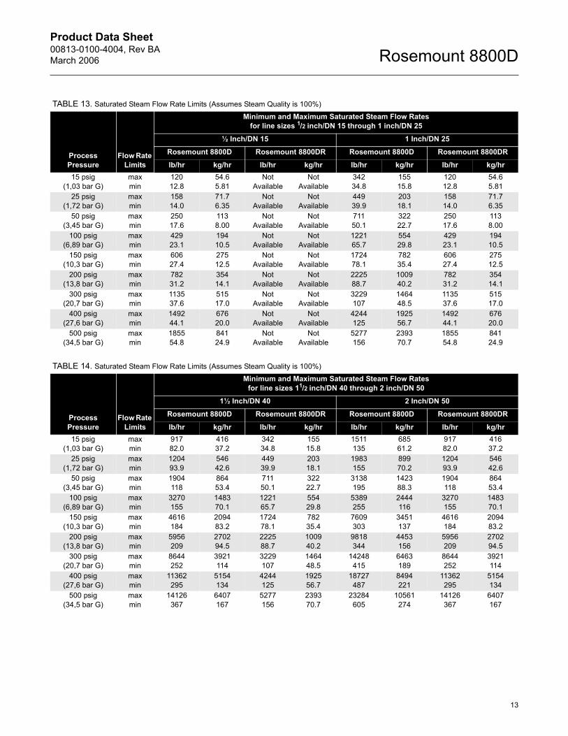
TABLE 13. Saturated Steam Flow Rate Limits (Assumes Steam Quality is 100%)
Process Pressure
Flow Rate Limits
Minimum and Maximum Saturated Steam Flow Rates for line sizes 1/2 inch/DN 15 through 1 inch/DN 25
½ Inch/DN 15 1 Inch/DN 25
Rosemount 8800D Rosemount 8800DR Rosemount 8800D Rosemount 8800DR
lb/hr kg/hr lb/hr kg/hr lb/hr kg/hr lb/hr kg/hr15 psig
(1,03 bar G)maxmin
12012.8
54.65.81
Not Available
Not Available
34234.8
15515.8
12012.8
54.65.81
25 psig(1,72 bar G)
maxmin
15814.0
71.76.35
Not Available
Not Available
44939.9
20318.1
15814.0
71.76.35
50 psig(3,45 bar G)
maxmin
25017.6
1138.00
Not Available
Not Available
71150.1
32222.7
25017.6
1138.00
100 psig(6,89 bar G)
maxmin
42923.1
19410.5
Not Available
Not Available
122165.7
55429.8
42923.1
19410.5
150 psig(10,3 bar G)
maxmin
60627.4
27512.5
Not Available
Not Available
172478.1
78235.4
60627.4
27512.5
200 psig(13,8 bar G)
maxmin
78231.2
35414.1
Not Available
Not Available
222588.7
100940.2
78231.2
35414.1
300 psig(20,7 bar G)
maxmin
113537.6
51517.0
Not Available
Not Available
3229107
146448.5
113537.6
51517.0
400 psig(27,6 bar G)
maxmin
149244.1
67620.0
Not Available
Not Available
4244125
192556.7
149244.1
67620.0
500 psig(34,5 bar G)
maxmin
185554.8
84124.9
Not Available
Not Available
5277156
239370.7
185554.8
84124.9
TABLE 14. Saturated Steam Flow Rate Limits (Assumes Steam Quality is 100%)
Process Pressure
Flow Rate Limits
Minimum and Maximum Saturated Steam Flow Rates for line sizes 11/2 inch/DN 40 through 2 inch/DN 50
1½ Inch/DN 40 2 Inch/DN 50
Rosemount 8800D Rosemount 8800DR Rosemount 8800D Rosemount 8800DR
lb/hr kg/hr lb/hr kg/hr lb/hr kg/hr lb/hr kg/hr15 psig
(1,03 bar G)maxmin
91782.0
41637.2
34234.8
15515.8
1511135
68561.2
91782.0
41637.2
25 psig(1,72 bar G)
maxmin
120493.9
54642.6
44939.9
20318.1
1983155
89970.2
120493.9
54642.6
50 psig(3,45 bar G)
maxmin
1904118
86453.4
71150.1
32222.7
3138195
142388.3
1904118
86453.4
100 psig(6,89 bar G)
maxmin
3270155
148370.1
122165.7
55429.8
5389255
2444116
3270155
148370.1
150 psig(10,3 bar G)
maxmin
4616184
209483.2
172478.1
78235.4
7609303
3451137
4616184
209483.2
200 psig(13,8 bar G)
maxmin
5956209
270294.5
222588.7
100940.2
9818344
4453156
5956209
270294.5
300 psig(20,7 bar G)
maxmin
8644252
3921114
3229107
146448.5
14248415
6463189
8644252
3921114
400 psig(27,6 bar G)
maxmin
11362295
5154134
4244125
192556.7
18727487
8494221
11362295
5154134
500 psig(34,5 bar G)
maxmin
14126367
6407167
5277156
239370.7
23284605
10561274
14126367
6407167
13
Product Data Sheet00813-0100-4004, Rev BA
March 2006Rosemount 8800D
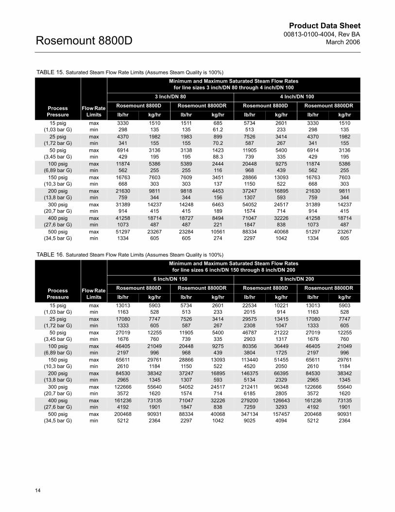
TABLE 15. Saturated Steam Flow Rate Limits (Assumes Steam Quality is 100%)
Process Pressure
Flow Rate Limits
Minimum and Maximum Saturated Steam Flow Rates for line sizes 3 inch/DN 80 through 4 inch/DN 100
3 Inch/DN 80 4 Inch/DN 100
Rosemount 8800D Rosemount 8800DR Rosemount 8800D Rosemount 8800DR
lb/hr kg/hr lb/hr kg/hr lb/hr kg/hr lb/hr kg/hr15 psig
(1,03 bar G)maxmin
3330298
1510135
1511135
68561.2
5734513
2601233
3330298
1510135
25 psig(1,72 bar G)
maxmin
4370341
1982155
1983155
89970.2
7526587
3414267
4370341
1982155
50 psig(3,45 bar G)
maxmin
6914429
3136195
3138195
142388.3
11905739
5400335
6914429
3136195
100 psig(6,89 bar G)
maxmin
11874562
5386255
5389255
2444116
20448968
9275439
11874562
5386255
150 psig(10,3 bar G)
maxmin
16763668
7603303
7609303
3451137
288661150
13093522
16763668
7603303
200 psig(13,8 bar G)
maxmin
21630759
9811344
9818344
4453156
372471307
16895593
21630759
9811344
300 psig(20,7 bar G)
maxmin
31389914
14237415
14248415
6463189
540521574
24517714
31389914
14237415
400 psig(27,6 bar G)
maxmin
412581073
18714487
18727487
8494221
710471847
32226838
412581073
18714487
500 psig(34,5 bar G)
maxmin
512971334
23267605
23284605
10561274
883342297
400681042
512971334
23267605
TABLE 16. Saturated Steam Flow Rate Limits (Assumes Steam Quality is 100%)
Process Pressure
Flow Rate Limits
Minimum and Maximum Saturated Steam Flow Rates for line sizes 6 inch/DN 150 through 8 inch/DN 200
6 Inch/DN 150 8 Inch/DN 200
Rosemount 8800D Rosemount 8800DR Rosemount 8800D Rosemount 8800DR
lb/hr kg/hr lb/hr kg/hr lb/hr kg/hr lb/hr kg/hr15 psig
(1,03 bar G)maxmin
130131163
5903528
5734513
2601233
225342015
10221914
130131163
5903528
25 psig(1,72 bar G)
maxmin
170801333
7747605
7526587
3414267
295752308
134151047
170801333
7747605
50 psig(3,45 bar G)
maxmin
270191676
12255760
11905739
5400335
467872903
212221317
270191676
12255760
100 psig(6,89 bar G)
maxmin
464052197
21049996
20448968
9275439
803563804
364491725
464052197
21049996
150 psig(10,3 bar G)
maxmin
656112610
297611184
288661150
13093522
1134404520
514552050
656112610
297611184
200 psig(13,8 bar G)
maxmin
845302965
383421345
372471307
16895593
1463755134
663952329
845302965
383421345
300 psig(20,7 bar G)
maxmin
1226663572
556401620
540521574
24517714
2124116185
963482805
1226663572
556401620
400 psig(27,6 bar G)
maxmin
1612364192
731351901
710471847
32226838
2792007259
1266433293
1612364192
731351901
500 psig(34,5 bar G)
maxmin
2004685212
909312364
883342297
400681042
3471349025
1574574094
2004685212
909312364
14
Product Data Sheet00813-0100-4004, Rev BAMarch 2006 Rosemount 8800D
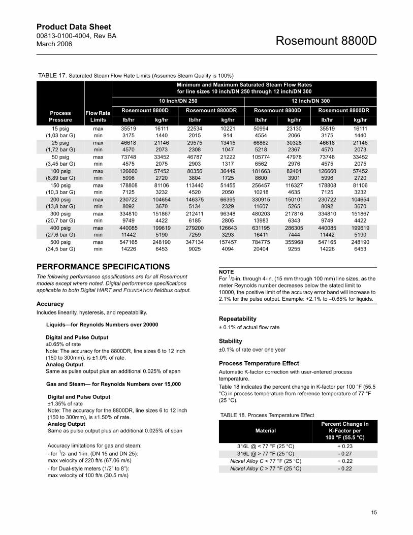
PERFORMANCE SPECIFICATIONSThe following performance specifications are for all Rosemount models except where noted. Digital performance specifications applicable to both Digital HART and FOUNDATION fieldbus output.
AccuracyIncludes linearity, hysteresis, and repeatability.
Liquids—for Reynolds Numbers over 20000
Gas and Steam— for Reynolds Numbers over 15,000
NOTEFor 1/2-in. through 4-in. (15 mm through 100 mm) line sizes, as the meter Reynolds number decreases below the stated limit to 10000, the positive limit of the accuracy error band will increase to 2.1% for the pulse output. Example: +2.1% to –0.65% for liquids.
Repeatability± 0.1% of actual flow rate
Stability±0.1% of rate over one year
Process Temperature EffectAutomatic K-factor correction with user-entered process temperature.Table 18 indicates the percent change in K-factor per 100 °F (55.5 °C) in process temperature from reference temperature of 77 °F (25 °C).
TABLE 17. Saturated Steam Flow Rate Limits (Assumes Steam Quality is 100%)
Process Pressure
Flow Rate Limits
Minimum and Maximum Saturated Steam Flow Rates for line sizes 10 inch/DN 250 through 12 inch/DN 300
10 Inch/DN 250 12 Inch/DN 300
Rosemount 8800D Rosemount 8800DR Rosemount 8800D Rosemount 8800DR
lb/hr kg/hr lb/hr kg/hr lb/hr kg/hr lb/hr kg/hr15 psig
(1,03 bar G)maxmin
355193175
161111440
225342015
10221914
509944554
231302066
355193175
161111440
25 psig(1,72 bar G)
maxmin
466184570
211462073
295752308
134151047
668625218
303282367
466184570
211462073
50 psig(3,45 bar G)
maxmin
737484575
334522075
467872903
212221317
1057746562
479782976
737484575
334522075
100 psig(6,89 bar G)
maxmin
1266605996
574522720
803563804
364491725
1816638600
824013901
1266605996
574522720
150 psig(10,3 bar G)
maxmin
1788087125
811063232
1134404520
514552050
25645710218
1163274635
1788087125
811063232
200 psig(13,8 bar G)
maxmin
2307228092
1046543670
1463755134
663952329
33091511607
1501015265
2307228092
1046543670
300 psig(20,7 bar G)
maxmin
3348109749
1518674422
2124116185
963482805
48020313983
2178166343
3348109749
1518674422
400 psig(27,6 bar G)
maxmin
44008511442
1996195190
2792007259
1266433293
63119516411
2863057444
44008511442
1996195190
500 psig(34,5 bar G)
maxmin
54716514226
2481906453
3471349025
1574574094
78477520404
3559689255
54716514226
2481906453
Digital and Pulse Output±0.65% of rateNote: The accuracy for the 8800DR, line sizes 6 to 12 inch (150 to 300mm), is ±1.0% of rate.Analog OutputSame as pulse output plus an additional 0.025% of span
Digital and Pulse Output±1.35% of rateNote: The accuracy for the 8800DR, line sizes 6 to 12 inch (150 to 300mm), is ±1.50% of rate.Analog OutputSame as pulse output plus an additional 0.025% of span
Accuracy limitations for gas and steam:- for 1/2- and 1-in. (DN 15 and DN 25): max velocity of 220 ft/s (67.06 m/s)- for Dual-style meters (1/2” to 8”): max velocity of 100 ft/s (30.5 m/s)
TABLE 18. Process Temperature Effect
MaterialPercent Change in
K-Factor per 100 °F (55.5 °C)
316L @ < 77 °F (25 °C) + 0.23316L @ > 77 °F (25 °C) - 0.27
Nickel Alloy C < 77 °F (25 °C) + 0.22Nickel Alloy C > 77 °F (25 °C) - 0.22
15
Product Data Sheet00813-0100-4004, Rev BA
March 2006Rosemount 8800D
Ambient Temperature Effect
Digital and Pulse OutputsNo effect
Analog Output±0.1% of span from –58 to 185 °F (–50 to 85 °C)
Vibration EffectAn output with no process flow may be detected if sufficiently high vibration is present.The meter design will minimize this effect, and the factory settings for signal processing are selected to eliminate these errors for most applications.If an output error at zero flow is still detected, it can be eliminated by adjusting the low flow cutoff, trigger level, or low-pass filter.As the process begins to flow through the meter, most vibration effects are quickly overcome by the flow signal. At or near the minimum liquid flow rate in a normal pipe mounted installation, the maximum vibration should be 0.087-inch (2,21 mm) double amplitude displacement or 1 g acceleration, whichever is smaller. At or near the minimum gas flow rate in a normal pipe mounted installation, the maximum vibration should be 0.043-inch (1,09 mm) double amplitude displacement or 1/2 g acceleration, whichever is smaller.
Mounting Position EffectMeter will meet accuracy specifications when mounted in horizontal, vertical, or inclined pipelines. Best practice for mounting in a horizontal pipe is to orient the shedder bar in the horizontal plane. This will prevent solids in liquid applications and liquid in gas/steam applications from disrupting the shedding frequency.
EMI/RFI Effect
HART AnalogOutput error less than ±0.025% of span with twisted pair from 80-1000 MHz for radiated field strength of 10 V/m and from 0.15-80 MHz for conducted RF of 3V (tested per EN61326).
Foundation fieldbus and Digital HARTNo affect on the values that are being given if using HART digital signal or FOUNDATION fieldbus.
Magnetic-Field Interference
HART AnalogOutput error less than ±0.025% of span at 30 A/m (rms); meets IEC 60770-1984, Section 6.2.9.
Foundation fieldbusNo effect on digital output accuracy at 30 A/m (rms). Tested per EN 61326.
Series Mode Noise Rejection
HART AnalogOutput error less than ±0.025% of span at 1 V rms, 60 Hz; meets IEC 60770-1984, Section 6.2.4.2.
Foundation fieldbusNo effect on digital output accuracy at 1 V rms 60 Hz. Meets IEC 60770-1984, Section 6.2.4.2
Common Mode Noise Rejection
HART AnalogOutput error less than ±0.025% of span at 30 V rms, 60 Hz; meets IEC 60770-1984, Section 6.2.4.1.
Foundation fieldbusNo effect on digital output accuracy at 250 V rms, 60 Hz. According to FF-830-PS-2.0 test case 8.2.
Power Supply Effect
HART AnalogLess than 0.005% of span per volt
Foundation fieldbusNo effect on accuracy.
16
Product Data Sheet00813-0100-4004, Rev BAMarch 2006 Rosemount 8800D
PHYSICAL SPECIFICATIONS
NACE ComplianceMaterials of Construction meet NACE material recommendations per MR0175 for sour oilfield production environments. Environmental limits apply to certain materials. Consult latest standard for details. Selected materials also conform to NACE MR0103 for refining environments.
Electrical Connections1/2 –14 NPT, PG 13.5, or M20 � 1.5 conduit threads; screw terminals provided for 4–20 mA and pulse output connections; communicator connections permanently fixed to terminal block.
Non-Wetted Materials
HousingLow-copper aluminum (FM Type 4X, CSA Type 4X, IP66)
PaintPolyurethane
Cover O-ringsBuna-N
Flanges316/316L lap joint
Process-Wetted Materials
Meter Body316L wrought stainless and CF-3M cast stainless or N06022 wrought Nickel Alloy and CW2M cast Nickel Alloy. Other material grades available. Consult factory for other materials of construction.
Flanges 316/316L stainless steelNickel Alloy N06022 Weld Neck
CollarsNickel Alloy N06022
Process ConnectionsMounts between the following flange configurations:ASME B16.5 (ANSI): Class 150, 300, 600, 900, 1500DIN: PN 10, 16, 25, 40, 64, 100, 160JIS: 10K, 20K, and 40K
Mounting
Integral (Standard)Electronics are mounted on meter body.
Remote (Optional)Electronics may be mounted remote from the meter body. Interconnecting coaxial cable available in nonadjustable 10, 20, and 30 ft (3,0, 6,1, and 9,1 m) lengths. Consult factory for non-standard lengths up to 75 ft (22,9 m). Remote mounting hardware includes a polyurethane painted, carbon steel pipe mount bracket with one carbon steel u-bolt.
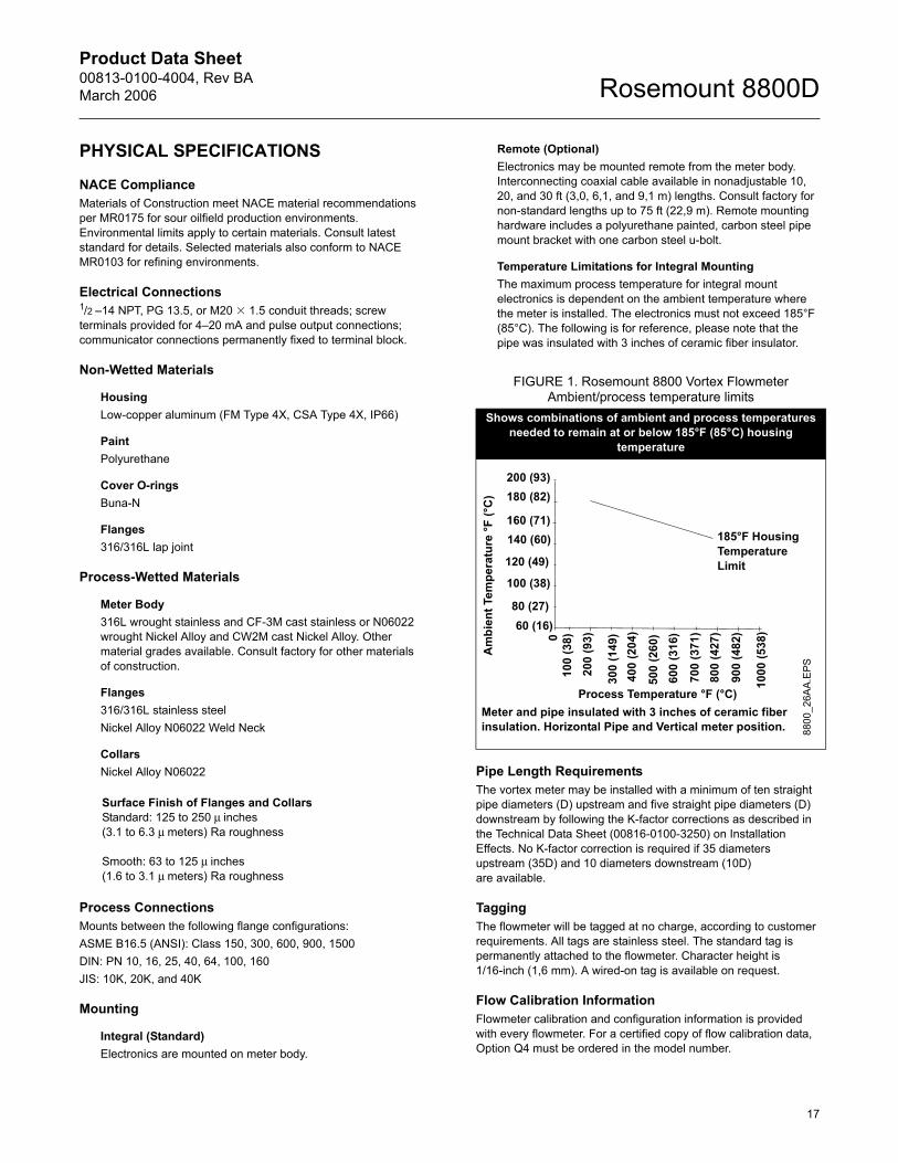
Temperature Limitations for Integral MountingThe maximum process temperature for integral mount electronics is dependent on the ambient temperature where the meter is installed. The electronics must not exceed 185°F (85°C). The following is for reference, please note that the pipe was insulated with 3 inches of ceramic fiber insulator.
Pipe Length RequirementsThe vortex meter may be installed with a minimum of ten straight pipe diameters (D) upstream and five straight pipe diameters (D) downstream by following the K-factor corrections as described in the Technical Data Sheet (00816-0100-3250) on Installation Effects. No K-factor correction is required if 35 diameters upstream (35D) and 10 diameters downstream (10D) are available.
TaggingThe flowmeter will be tagged at no charge, according to customer requirements. All tags are stainless steel. The standard tag is permanently attached to the flowmeter. Character height is 1/16-inch (1,6 mm). A wired-on tag is available on request.
Flow Calibration InformationFlowmeter calibration and configuration information is provided with every flowmeter. For a certified copy of flow calibration data, Option Q4 must be ordered in the model number.
Surface Finish of Flanges and CollarsStandard: 125 to 250 μ inches (3.1 to 6.3 μ meters) Ra roughness
Smooth: 63 to 125 μ inches(1.6 to 3.1 μ meters) Ra roughness
FIGURE 1. Rosemount 8800 Vortex Flowmeter Ambient/process temperature limits
Shows combinations of ambient and process temperatures needed to remain at or below 185°F (85°C) housing
temperature
200 (93)180 (82)
160 (71)140 (60)
120 (49)
100 (38)
80 (27)60 (16)
0
200
(93)
300
(149
)40
0 (2
04)
500
(260
)60
0 (3
16)
700
(371
)80
0 (4
27)
900
(482
)
1000
(538
)
100
(38)
Am
bien
t Tem
pera
ture
°F (°
C)
Process Temperature °F (°C)
185°F Housing Temperature Limit
Meter and pipe insulated with 3 inches of ceramic fiber insulation. Horizontal Pipe and Vertical meter position. 88
00_2
6AA
.EPS
17
Product Data Sheet00813-0100-4004, Rev BA
March 2006Rosemount 8800D
Product Certifications
Approved Manufacturing LocationsRosemount Inc. — Eden Prairie, Minnesota, USAEmerson Process Management BV - Veenendaal, The
Netherlands
EUROPEAN DIRECTIVE INFORMATIONThe CE Declaration of Conformity for all applicable European directives for this product can be found on our website at www.rosemount.com. A hard copy may be obtained by contacting our local sales office.
ATEX DirectiveRosemount Inc. complies with the ATEX Directive.
Flameproof enclosure EEx d protection type in accordance with EN50018
• Transmitters with Flameproof enclosure type protection shall only be opened when power is removed.
• Closing of entries in the device must be carried out using the appropriate EEx d metal cable gland or metal blanking plug.
• Do not exceed the energy level, which is stated on the approval label.
Type n protection type in accordance with EN50021Closing of entries in the device must be carried out using the appropriate EExe or EExn metal cable gland and metal blanking plug or any appropriate ATEX approved cable gland and blanking plug with IP66 rating certified by an EU approved certification body.
EUROPEAN PRESSURE EQUIPMENT DIRECTIVE (PED)
Rosemount 8800 Vortex Flowmeter Line Size 40 mm to 300 mmCertificate Number PED-H-100
0575Module H Conformity AssessmentMandatory CE-marking for flowmeters in accordance with Article 15 of the PED can be found on the flowtube body. Flowmeter categories I – IV, use module H for conformity assessment procedures.
Rosemount 8800 Vortex Flowmeter Line Size 15 mm and 25 mmSound Engineering PracticeFlowmeters that are SEP or Category I with Explosion-Proof protection are outside the scope of PED and cannot be marked for compliance with PED.
18
Product Data Sheet00813-0100-4004, Rev BAMarch 2006 Rosemount 8800D
HAZARDOUS LOCATION CERTIFICATIONS
Rosemount 8800D with HART Protocol
North American Certifications
Factory Mutual (FM)E5 Explosion-Proof for Class I, Division 1, Groups B, C, and D;
Dust-ignition proof for Class II/III, Division 1, Groups E, F, and G; Temp Code T6 (Ta = -50°C to 70°C)Conduit Seal not requiredEnclosure Type 4X.
I5 Intrinsically safe for use in Class I, Division 1, Groups A, B, C, and D; Class I, Zone 0, AEx ia IIC T4 (Ta = 70°C);Class II/III, Division 1, Groups E, F, and G locations when connected in accordance with Rosemount drawings 08800-0116;Non-incendive for Class I, Division 2, Groups A, B, C, and D and Suitable for Class I, Division 2, Groups A, B, C, and D, with non-incendive field wiring (NIFW) when installed in accordance with Rosemount drawing 08800-0116;Temperature code T4 (Ta = 70°C)Enclosure Type 4X.
K5 E5 and I5 Combination
Canadian Standards Association (CSA)E6 Explosion-Proof for Class I, Division 1, Groups B, C, and D;
Dust-ignition proof for Class II and Class III, Division 1, Groups E, F, and G; Temp Code T6 (TA = 70°C)Factory sealed.Suitable for Class I, Division 2, Groups A, B, C, and D; Temp Code T3C.Enclosure Type 4X.
I6 Intrinsically safe for Class I, Division 1, Groups A, B, C, and D; When connected in accordance with Rosemount drawing 08800-0112;Temperature code T3CEnclosure Type 4X.
K6 E6 and I6 Combination
European Certifications
ATEX Intrinsic Safety I1 Certification No. Baseefa05ATEX0084X
ATEX Marking II 1 GEEx ia IIC T5 (-60°C ≤ Ta ≤ 40°C)EEx ia IIC T4 (-60°C ≤ Ta ≤ 70°C)
Input Parameters:Ui = 30 VDCIi(1) = 185 mAPi
(1) = 1.0 WCi = 0 μFLi = 0.97 mH
0575
SPECIAL CONDITIONSThe apparatus is not capable of withstanding the 500V insulation test required by clause 6.4.12 of EN50020. This must be considered during installation.
ATEX Type N CertificationN1 Certification No. Baseefa05ATEX0085X
ATEX Marking II 3 GEEx nL II T5 (-40°C ≤ Ta ≤ 70°C)Input Parameters:
Ui = 42 V dc MaxCi = 0 μFLi = 0.97 mH
SPECIAL CONDITIONSThe apparatus is not capable of withstanding the 500V insulation test required by clause 9.1 of EN50021. This must be taken into account when installing the apparatus.
ATEX Flameproof CertificationE1 Certification No. KEMA99ATEX3852X
ATEX Marking Remote Mount:Transmitter: II 2(1) G
EEx d [ia]IIC T6 (-50°C ≤ Ta ≤ 70°C)Meter Body: II 1 G
EEx ia IIC T6 (-50°C ≤ Ta ≤ 70°C)ATEX Marking Integral Mount: II 1/2 G
EEx d [ia] IIC T6 (-50°C ≤ Ta ≤ 70°C) 0575
V = 42 Vdc MaxUm = 250V
SPECIAL CONDITIONSWhen the equipment is installed, precautions must be taken to ensure, taking account with the effect of the fluid temperature, that the ambient temperature of the electrical parts of the equipment is comprised between -50°C and 70°C. The remote mounted sensor may only be connected to the transmitter with the associated cable, supplied by the manufacturer.
ATEX Dust Certification ND Certification No. Baseefa05ATEX0086
ATEX Marking II 1 D T90°C (-20°C ≤ Ta ≤ 70°C)Ui = 42 V dc
0575K1 E1, I1, N1 and ND Combination
(1) Total for transmitter
19
Product Data Sheet00813-0100-4004, Rev BA
March 2006Rosemount 8800D
International IECEx Certifications
Intrinsic SafetyI7 Certification No. IECEx BAS 05.0028X
Ex ia IIC T5 (-60°C ≤ Ta ≤ 40°C)Ex ia IIC T4 (-60°C ≤ Ta ≤ 70°C)
Input Parameters:Ui = 30 VDCIi = 185 mAPi = 1.0 WCi = 0 μFLi = 0.97 mH
SPECIAL CONDITIONSThe apparatus is not capable of withstanding the 500V test as defined in clause 6.4.12 of IEC 60079-11. This must be considered during installation.
Type N CertificationN7 Certification No. IECEx BAS 05.0029
Ex nC IIC T5 (-40°C ≤Ta ≤ 70°C) Ui = 42 V dc
Flameproof CertificationE7 Certification No. IECEx KEM 05.0017X
Marking Remote Mount:Transmitter: Ex d [ia] IIC T6 (-50°C ≤ Ta ≤ 70°C)Meter Body: Ex ia IIC T6 (-50°C ≤ Ta ≤ 70°C)
Marking Integral Mount: Ex d [ia] IIC T6(-50°C ≤ Ta ≤ 70°C)
V = 42 Vdc MaxUm = 250V
SPECIAL CONDITIONSWhen the equipment is installed particular precautions must be taken to ensure, taking account with the effect of the fluid temperature, that the ambient temperature of the electrical parts of the apparatus is comprised between -50°C and 70°C.The remote mounted sensor may only be connected to the transmitter with the associated cable, supplied by the manufacturer.
K7 E7, I7, and N7 Combination
Chinese Certifications (NEPSI)
Flameproof CertificationE3 Pending
Intrinsic SafetyI3 PendingK3 E3 and I3 Combination
Other CertificationsKB E5, I5, E6, and I6 Combination
20
Product Data Sheet00813-0100-4004, Rev BAMarch 2006 Rosemount 8800D
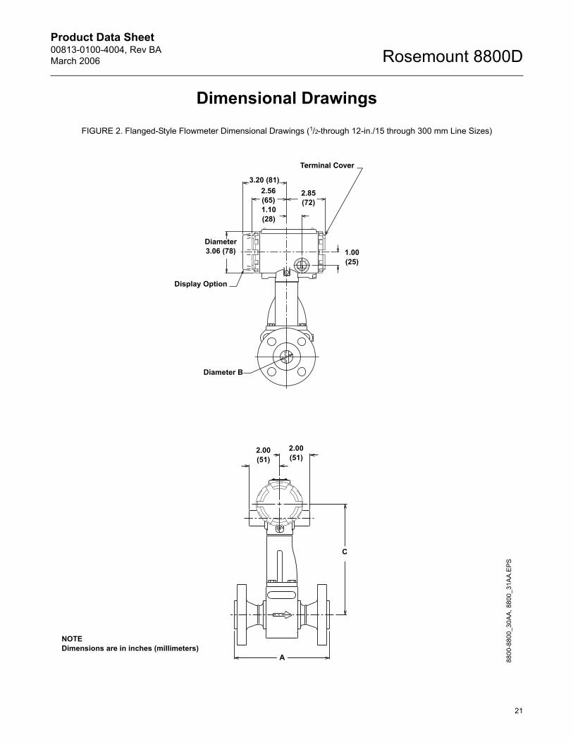
Dimensional Drawings
FIGURE 2. Flanged-Style Flowmeter Dimensional Drawings (1/2-through 12-in./15 through 300 mm Line Sizes)
Terminal Cover
Display Option
Diameter 3.06 (78)
Diameter B
3.20 (81)2.56 (65)
2.85 (72)
1.10 (28)
1.00 (25)
C
A
2.00 (51)
2.00 (51)
NOTEDimensions are in inches (millimeters)
8800
-880
0_30
AA, 8
800_
31A
A.E
PS
21
Product Data Sheet00813-0100-4004, Rev BA
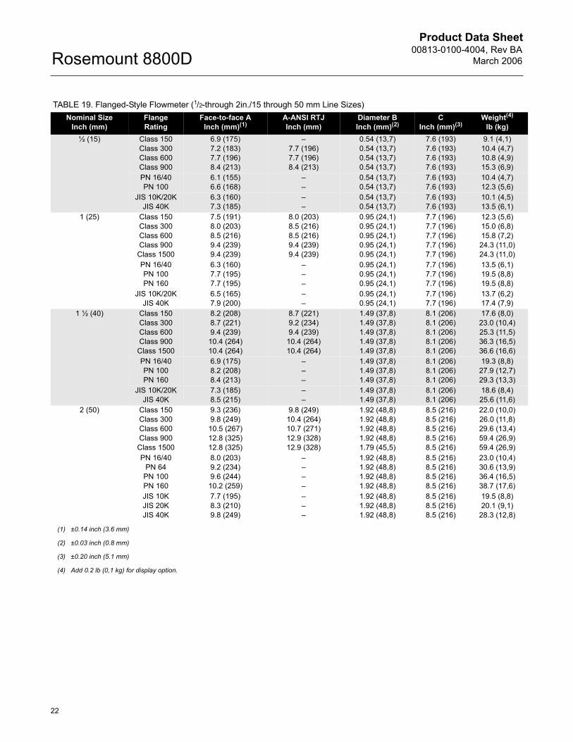
March 2006Rosemount 8800D
TABLE 19. Flanged-Style Flowmeter (1/2-through 2in./15 through 50 mm Line Sizes)Nominal Size
Inch (mm)Flange Rating
Face-to-face A Inch (mm)(1)
A-ANSI RTJ Inch (mm)
Diameter B Inch (mm)(2)
C Inch (mm)(3)
Weight(4) lb (kg)
½ (15) Class 150Class 300Class 600Class 900
6.9 (175)7.2 (183)7.7 (196)8.4 (213)
–7.7 (196)7.7 (196)8.4 (213)
0.54 (13,7)0.54 (13,7)0.54 (13,7)0.54 (13,7)
7.6 (193)7.6 (193)7.6 (193)7.6 (193)
9.1 (4,1)10.4 (4,7)10.8 (4,9)15.3 (6,9)
PN 16/40PN 100
6.1 (155)6.6 (168)
––
0.54 (13,7)0.54 (13,7)
7.6 (193)7.6 (193)
10.4 (4,7)12.3 (5,6)
JIS 10K/20KJIS 40K
6.3 (160)7.3 (185)
––
0.54 (13,7)0.54 (13,7)
7.6 (193)7.6 (193)
10.1 (4,5)13.5 (6,1)
1 (25) Class 150Class 300Class 600Class 900
Class 1500
7.5 (191)8.0 (203)8.5 (216)9.4 (239)9.4 (239)
8.0 (203)8.5 (216)8.5 (216)9.4 (239)9.4 (239)
0.95 (24,1)0.95 (24,1)0.95 (24,1)0.95 (24,1)0.95 (24,1)
7.7 (196)7.7 (196)7.7 (196)7.7 (196)7.7 (196)
12.3 (5,6)15.0 (6,8)15.8 (7,2)24.3 (11,0)24.3 (11,0)
PN 16/40PN 100PN 160
6.3 (160)7.7 (195)7.7 (195)
–––
0.95 (24,1)0.95 (24,1)0.95 (24,1)
7.7 (196)7.7 (196)7.7 (196)
13.5 (6,1)19.5 (8,8)19.5 (8,8)
JIS 10K/20KJIS 40K
6.5 (165)7.9 (200)
––
0.95 (24,1)0.95 (24,1)
7.7 (196)7.7 (196)
13.7 (6,2)17.4 (7,9)
1 ½ (40) Class 150Class 300Class 600Class 900
Class 1500
8.2 (208)8.7 (221)9.4 (239)
10.4 (264)10.4 (264)
8.7 (221)9.2 (234)9.4 (239)
10.4 (264)10.4 (264)
1.49 (37,8)1.49 (37,8)1.49 (37,8)1.49 (37,8)1.49 (37,8)
8.1 (206)8.1 (206)8.1 (206)8.1 (206)8.1 (206)
17.6 (8,0)23.0 (10,4)25.3 (11,5)36.3 (16,5)36.6 (16,6)
PN 16/40PN 100PN 160
6.9 (175)8.2 (208)8.4 (213)
–––
1.49 (37,8)1.49 (37,8)1.49 (37,8)
8.1 (206)8.1 (206)8.1 (206)
19.3 (8,8)27.9 (12,7)29.3 (13,3)
JIS 10K/20KJIS 40K
7.3 (185)8.5 (215)
––
1.49 (37,8)1.49 (37,8)
8.1 (206)8.1 (206)
18.6 (8,4)25.6 (11,6)
2 (50) Class 150Class 300Class 600Class 900
Class 1500
9.3 (236)9.8 (249)
10.5 (267)12.8 (325)12.8 (325)
9.8 (249)10.4 (264)10.7 (271)12.9 (328)12.9 (328)
1.92 (48,8)1.92 (48,8)1.92 (48,8)1.92 (48,8)1.79 (45,5)
8.5 (216)8.5 (216)8.5 (216)8.5 (216)8.5 (216)
22.0 (10,0)26.0 (11,8)29.6 (13,4)59.4 (26,9)59.4 (26,9)
PN 16/40PN 64
PN 100PN 160
8.0 (203)9.2 (234)9.6 (244)
10.2 (259)
––––
1.92 (48,8)1.92 (48,8)1.92 (48,8)1.92 (48,8)
8.5 (216)8.5 (216)8.5 (216)8.5 (216)
23.0 (10,4)30.6 (13,9)36.4 (16,5)38.7 (17,6)
JIS 10KJIS 20KJIS 40K
7.7 (195)8.3 (210)9.8 (249)
–––
1.92 (48,8)1.92 (48,8)1.92 (48,8)
8.5 (216)8.5 (216)8.5 (216)
19.5 (8,8)20.1 (9,1)
28.3 (12,8)
(1) ±0.14 inch (3.6 mm)
(2) ±0.03 inch (0.8 mm)
(3) ±0.20 inch (5.1 mm)
(4) Add 0.2 lb (0,1 kg) for display option.
22
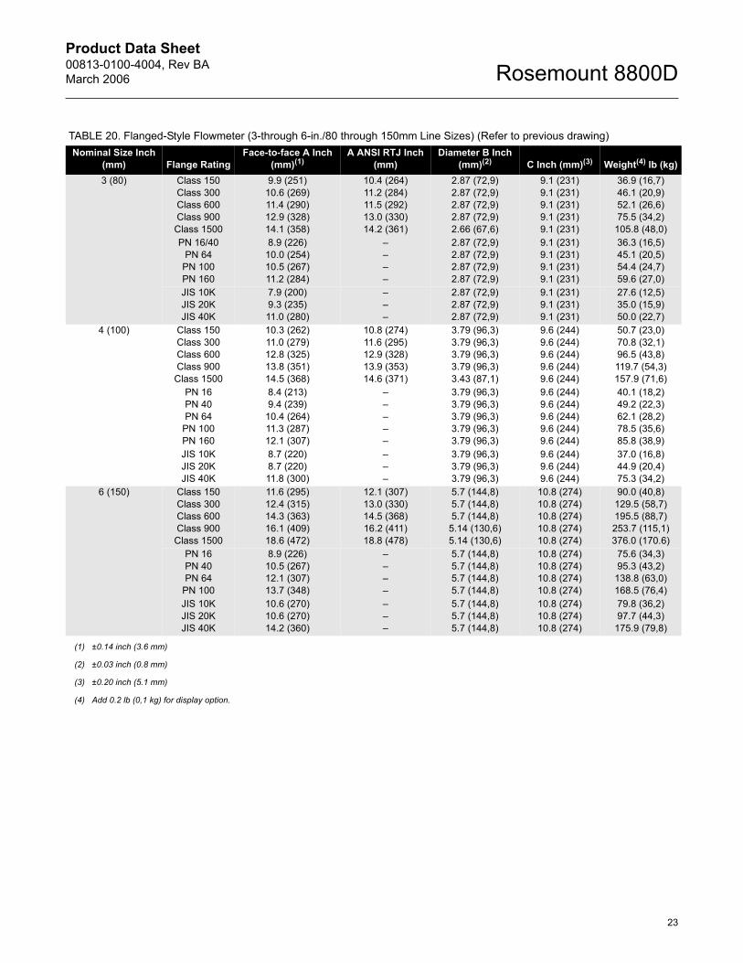
Product Data Sheet00813-0100-4004, Rev BAMarch 2006 Rosemount 8800D
TABLE 20. Flanged-Style Flowmeter (3-through 6-in./80 through 150mm Line Sizes) (Refer to previous drawing)Nominal Size Inch
(mm) Flange RatingFace-to-face A Inch
(mm)(1)A ANSI RTJ Inch
(mm)Diameter B Inch
(mm)(2) C Inch (mm)(3) Weight(4) lb (kg)3 (80) Class 150
Class 300Class 600Class 900
Class 1500
9.9 (251)10.6 (269)11.4 (290)12.9 (328)14.1 (358)
10.4 (264)11.2 (284)11.5 (292)13.0 (330)14.2 (361)
2.87 (72,9)2.87 (72,9)2.87 (72,9)2.87 (72,9)2.66 (67,6)
9.1 (231)9.1 (231)9.1 (231)9.1 (231)9.1 (231)
36.9 (16,7)46.1 (20,9)52.1 (26,6)75.5 (34,2)
105.8 (48,0)PN 16/40
PN 64PN 100PN 160
8.9 (226)10.0 (254)10.5 (267)11.2 (284)
––––
2.87 (72,9)2.87 (72,9)2.87 (72,9)2.87 (72,9)
9.1 (231)9.1 (231)9.1 (231)9.1 (231)
36.3 (16,5)45.1 (20,5)54.4 (24,7)59.6 (27,0)
JIS 10KJIS 20KJIS 40K
7.9 (200)9.3 (235)11.0 (280)
–––
2.87 (72,9)2.87 (72,9)2.87 (72,9)
9.1 (231)9.1 (231)9.1 (231)
27.6 (12,5)35.0 (15,9)50.0 (22,7)
4 (100) Class 150Class 300Class 600Class 900
Class 1500
10.3 (262)11.0 (279)12.8 (325)13.8 (351)14.5 (368)
10.8 (274)11.6 (295)12.9 (328)13.9 (353)14.6 (371)
3.79 (96,3)3.79 (96,3)3.79 (96,3)3.79 (96,3)3.43 (87,1)
9.6 (244)9.6 (244)9.6 (244)9.6 (244)9.6 (244)
50.7 (23,0)70.8 (32,1)96.5 (43,8)119.7 (54,3)157.9 (71,6)
PN 16PN 40PN 64
PN 100PN 160
8.4 (213)9.4 (239)
10.4 (264)11.3 (287)12.1 (307)
–––––
3.79 (96,3)3.79 (96,3)3.79 (96,3)3.79 (96,3)3.79 (96,3)
9.6 (244)9.6 (244)9.6 (244)9.6 (244)9.6 (244)
40.1 (18,2)49.2 (22,3)62.1 (28,2)78.5 (35,6)85.8 (38,9)
JIS 10KJIS 20KJIS 40K
8.7 (220)8.7 (220)11.8 (300)
–––
3.79 (96,3)3.79 (96,3)3.79 (96,3)
9.6 (244)9.6 (244)9.6 (244)
37.0 (16,8)44.9 (20,4)75.3 (34,2)
6 (150) Class 150Class 300Class 600Class 900
Class 1500
11.6 (295)12.4 (315)14.3 (363)16.1 (409)18.6 (472)
12.1 (307)13.0 (330)14.5 (368)16.2 (411)18.8 (478)
5.7 (144,8)5.7 (144,8)5.7 (144,8)
5.14 (130,6)5.14 (130,6)
10.8 (274)10.8 (274)10.8 (274)10.8 (274)10.8 (274)
90.0 (40,8)129.5 (58,7)195.5 (88,7)253.7 (115,1)376.0 (170.6)
PN 16PN 40PN 64
PN 100
8.9 (226)10.5 (267)12.1 (307)13.7 (348)
––––
5.7 (144,8)5.7 (144,8)5.7 (144,8)5.7 (144,8)
10.8 (274)10.8 (274)10.8 (274)10.8 (274)
75.6 (34,3)95.3 (43,2)
138.8 (63,0)168.5 (76,4)
JIS 10KJIS 20KJIS 40K
10.6 (270)10.6 (270)14.2 (360)
–––
5.7 (144,8)5.7 (144,8)5.7 (144,8)
10.8 (274)10.8 (274)10.8 (274)
79.8 (36,2)97.7 (44,3)
175.9 (79,8)
(1) ±0.14 inch (3.6 mm)
(2) ±0.03 inch (0.8 mm)
(3) ±0.20 inch (5.1 mm)
(4) Add 0.2 lb (0,1 kg) for display option.
23
Product Data Sheet00813-0100-4004, Rev BA
March 2006Rosemount 8800D
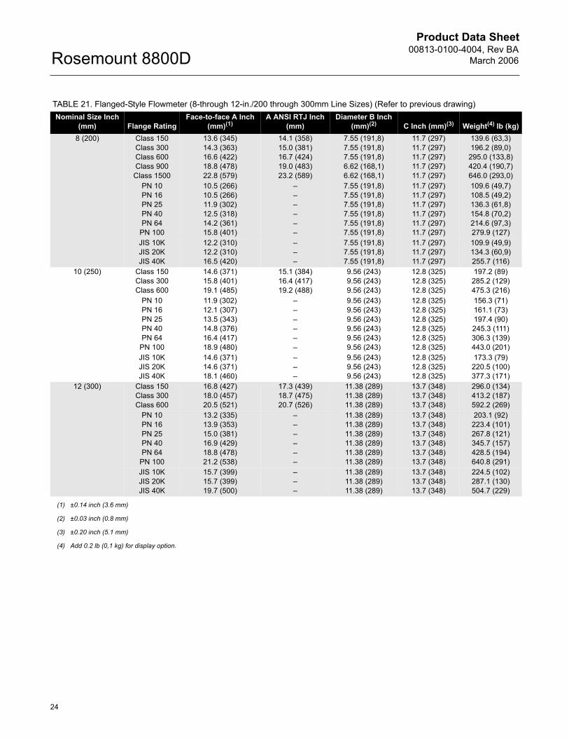
TABLE 21. Flanged-Style Flowmeter (8-through 12-in./200 through 300mm Line Sizes) (Refer to previous drawing)Nominal Size Inch
(mm) Flange RatingFace-to-face A Inch
(mm)(1)A ANSI RTJ Inch
(mm)Diameter B Inch
(mm)(2) C Inch (mm)(3) Weight(4) lb (kg)8 (200) Class 150
Class 300Class 600Class 900
Class 1500
13.6 (345)14.3 (363)16.6 (422)18.8 (478)22.8 (579)
14.1 (358)15.0 (381)16.7 (424)19.0 (483)23.2 (589)
7.55 (191,8)7.55 (191,8)7.55 (191,8)6.62 (168,1)6.62 (168,1)
11.7 (297)11.7 (297)11.7 (297)11.7 (297)11.7 (297)
139.6 (63,3)196.2 (89,0)
295.0 (133,8)420.4 (190,7)646.0 (293,0)
PN 10PN 16PN 25PN 40PN 64
PN 100
10.5 (266)10.5 (266)11.9 (302)12.5 (318)14.2 (361)15.8 (401)
––––––
7.55 (191,8)7.55 (191,8)7.55 (191,8)7.55 (191,8)7.55 (191,8)7.55 (191,8)
11.7 (297)11.7 (297)11.7 (297)11.7 (297)11.7 (297)11.7 (297)
109.6 (49,7)108.5 (49,2)136.3 (61,8)154.8 (70,2)214.6 (97,3)279.9 (127)
JIS 10KJIS 20KJIS 40K
12.2 (310)12.2 (310)16.5 (420)
–––
7.55 (191,8)7.55 (191,8)7.55 (191,8)
11.7 (297)11.7 (297)11.7 (297)
109.9 (49,9)134.3 (60,9)255.7 (116)
10 (250) Class 150Class 300Class 600
14.6 (371)15.8 (401)19.1 (485)
15.1 (384)16.4 (417)19.2 (488)
9.56 (243)9.56 (243)9.56 (243)
12.8 (325)12.8 (325)12.8 (325)
197.2 (89)285.2 (129)475.3 (216)
PN 10PN 16PN 25PN 40PN 64
PN 100
11.9 (302)12.1 (307)13.5 (343)14.8 (376)16.4 (417)18.9 (480)
––––––
9.56 (243)9.56 (243)9.56 (243)9.56 (243)9.56 (243)9.56 (243)
12.8 (325)12.8 (325)12.8 (325)12.8 (325)12.8 (325)12.8 (325)
156.3 (71)161.1 (73)197.4 (90)245.3 (111)306.3 (139)443.0 (201)
JIS 10KJIS 20KJIS 40K
14.6 (371)14.6 (371)18.1 (460)
–––
9.56 (243)9.56 (243)9.56 (243)
12.8 (325)12.8 (325)12.8 (325)
173.3 (79)220.5 (100)377.3 (171)
12 (300) Class 150Class 300Class 600
16.8 (427)18.0 (457)20.5 (521)
17.3 (439)18.7 (475)20.7 (526)
11.38 (289)11.38 (289)11.38 (289)
13.7 (348)13.7 (348)13.7 (348)
296.0 (134)413.2 (187)592.2 (269)
PN 10PN 16PN 25PN 40PN 64
PN 100
13.2 (335)13.9 (353)15.0 (381)16.9 (429)18.8 (478)21.2 (538)
––––––
11.38 (289)11.38 (289)11.38 (289)11.38 (289)11.38 (289)11.38 (289)
13.7 (348)13.7 (348)13.7 (348)13.7 (348)13.7 (348)13.7 (348)
203.1 (92)223.4 (101)267.8 (121)345.7 (157)428.5 (194)640.8 (291)
JIS 10KJIS 20KJIS 40K
15.7 (399)15.7 (399)19.7 (500)
–––
11.38 (289)11.38 (289)11.38 (289)
13.7 (348)13.7 (348)13.7 (348)
224.5 (102)287.1 (130)504.7 (229)
(1) ±0.14 inch (3.6 mm)
(2) ±0.03 inch (0.8 mm)
(3) ±0.20 inch (5.1 mm)
(4) Add 0.2 lb (0,1 kg) for display option.
24
Product Data Sheet00813-0100-4004, Rev BAMarch 2006 Rosemount 8800D
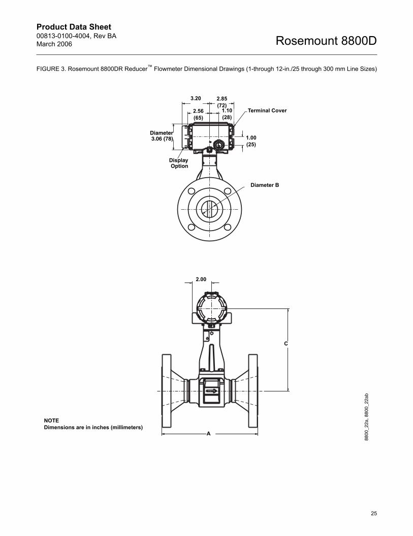
FIGURE 3. Rosemount 8800DR Reducer™ Flowmeter Dimensional Drawings (1-through 12-in./25 through 300 mm Line Sizes)
Diameter B
DisplayOption
1.00 (25)
3.20 2.85 (72)
2.56 (65)
1.10 (28)
Diameter3.06 (78)
Terminal Cover
NOTEDimensions are in inches (millimeters)
8800
_22a
, 880
0_22
ab
2.00
A
C
25
Product Data Sheet00813-0100-4004, Rev BA
March 2006Rosemount 8800D
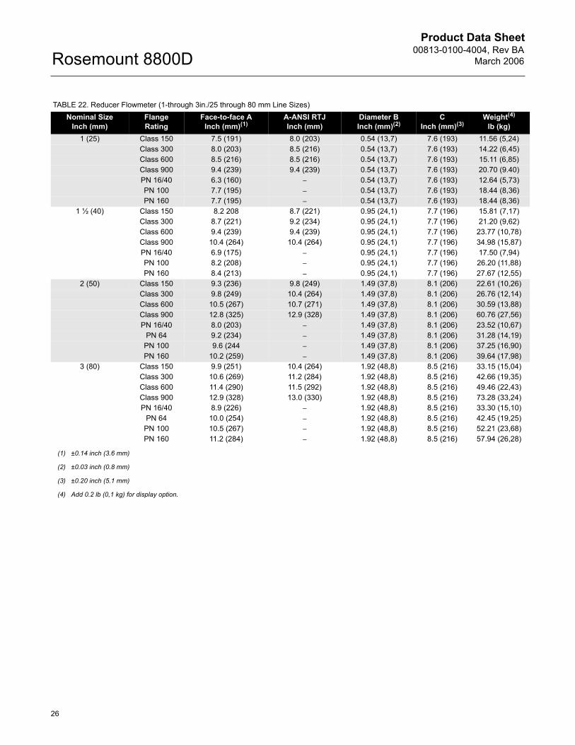
TABLE 22. Reducer Flowmeter (1-through 3in./25 through 80 mm Line Sizes)Nominal Size
Inch (mm)Flange Rating
Face-to-face A Inch (mm)(1)
A-ANSI RTJ Inch (mm)
Diameter B Inch (mm)(2)
C Inch (mm)(3)
Weight(4) lb (kg)
1 (25) Class 150 7.5 (191) 8.0 (203) 0.54 (13,7) 7.6 (193) 11.56 (5,24)Class 300 8.0 (203) 8.5 (216) 0.54 (13,7) 7.6 (193) 14.22 (6,45)Class 600 8.5 (216) 8.5 (216) 0.54 (13,7) 7.6 (193) 15.11 (6,85)Class 900 9.4 (239) 9.4 (239) 0.54 (13,7) 7.6 (193) 20.70 (9.40)PN 16/40 6.3 (160) – 0.54 (13,7) 7.6 (193) 12.64 (5,73)PN 100 7.7 (195) – 0.54 (13,7) 7.6 (193) 18.44 (8,36)PN 160 7.7 (195) – 0.54 (13,7) 7.6 (193) 18.44 (8,36)
1 ½ (40) Class 150 8.2 208 8.7 (221) 0.95 (24,1) 7.7 (196) 15.81 (7,17)Class 300 8.7 (221) 9.2 (234) 0.95 (24,1) 7.7 (196) 21.20 (9,62)Class 600 9.4 (239) 9.4 (239) 0.95 (24,1) 7.7 (196) 23.77 (10,78)Class 900 10.4 (264) 10.4 (264) 0.95 (24,1) 7.7 (196) 34.98 (15,87)PN 16/40 6.9 (175) – 0.95 (24,1) 7.7 (196) 17.50 (7,94)PN 100 8.2 (208) – 0.95 (24,1) 7.7 (196) 26.20 (11,88)PN 160 8.4 (213) – 0.95 (24,1) 7.7 (196) 27.67 (12,55)
2 (50) Class 150 9.3 (236) 9.8 (249) 1.49 (37,8) 8.1 (206) 22.61 (10,26)Class 300 9.8 (249) 10.4 (264) 1.49 (37,8) 8.1 (206) 26.76 (12,14)Class 600 10.5 (267) 10.7 (271) 1.49 (37,8) 8.1 (206) 30.59 (13,88)Class 900 12.8 (325) 12.9 (328) 1.49 (37,8) 8.1 (206) 60.76 (27,56)PN 16/40 8.0 (203) – 1.49 (37,8) 8.1 (206) 23.52 (10,67)
PN 64 9.2 (234) – 1.49 (37,8) 8.1 (206) 31.28 (14,19)PN 100 9.6 (244 – 1.49 (37,8) 8.1 (206) 37.25 (16,90)PN 160 10.2 (259) – 1.49 (37,8) 8.1 (206) 39.64 (17,98)
3 (80) Class 150 9.9 (251) 10.4 (264) 1.92 (48,8) 8.5 (216) 33.15 (15,04)Class 300 10.6 (269) 11.2 (284) 1.92 (48,8) 8.5 (216) 42.66 (19,35)Class 600 11.4 (290) 11.5 (292) 1.92 (48,8) 8.5 (216) 49.46 (22,43)Class 900 12.9 (328) 13.0 (330) 1.92 (48,8) 8.5 (216) 73.28 (33,24)PN 16/40 8.9 (226) – 1.92 (48,8) 8.5 (216) 33.30 (15,10)
PN 64 10.0 (254) – 1.92 (48,8) 8.5 (216) 42.45 (19,25)PN 100 10.5 (267) – 1.92 (48,8) 8.5 (216) 52.21 (23,68)PN 160 11.2 (284) – 1.92 (48,8) 8.5 (216) 57.94 (26,28)
(1) ±0.14 inch (3.6 mm)
(2) ±0.03 inch (0.8 mm)
(3) ±0.20 inch (5.1 mm)
(4) Add 0.2 lb (0,1 kg) for display option.
26
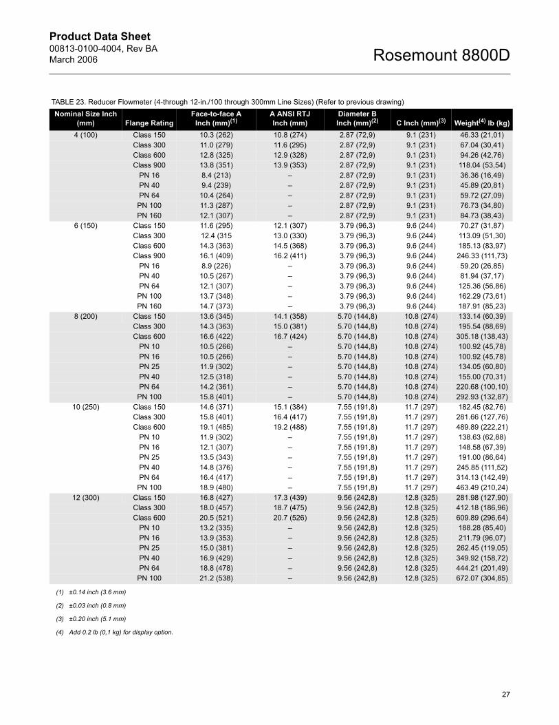
Product Data Sheet00813-0100-4004, Rev BAMarch 2006 Rosemount 8800D
TABLE 23. Reducer Flowmeter (4-through 12-in./100 through 300mm Line Sizes) (Refer to previous drawing)Nominal Size Inch
(mm) Flange RatingFace-to-face A
Inch (mm)(1)A ANSI RTJ Inch (mm)
Diameter B Inch (mm)(2) C Inch (mm)(3) Weight(4) lb (kg)
4 (100) Class 150 10.3 (262) 10.8 (274) 2.87 (72,9) 9.1 (231) 46.33 (21,01)Class 300 11.0 (279) 11.6 (295) 2.87 (72,9) 9.1 (231) 67.04 (30,41)Class 600 12.8 (325) 12.9 (328) 2.87 (72,9) 9.1 (231) 94.26 (42,76)Class 900 13.8 (351) 13.9 (353) 2.87 (72,9) 9.1 (231) 118.04 (53,54)
PN 16 8.4 (213) – 2.87 (72,9) 9.1 (231) 36.36 (16,49)PN 40 9.4 (239) – 2.87 (72,9) 9.1 (231) 45.89 (20,81)PN 64 10.4 (264) – 2.87 (72,9) 9.1 (231) 59.72 (27,09)
PN 100 11.3 (287) – 2.87 (72,9) 9.1 (231) 76.73 (34,80)PN 160 12.1 (307) – 2.87 (72,9) 9.1 (231) 84.73 (38,43)
6 (150) Class 150 11.6 (295) 12.1 (307) 3.79 (96,3) 9.6 (244) 70.27 (31,87)Class 300 12.4 (315 13.0 (330) 3.79 (96,3) 9.6 (244) 113.09 (51,30)Class 600 14.3 (363) 14.5 (368) 3.79 (96,3) 9.6 (244) 185.13 (83,97)Class 900 16.1 (409) 16.2 (411) 3.79 (96,3) 9.6 (244) 246.33 (111,73)
PN 16 8.9 (226) – 3.79 (96,3) 9.6 (244) 59.20 (26,85)PN 40 10.5 (267) – 3.79 (96,3) 9.6 (244) 81.94 (37,17)PN 64 12.1 (307) – 3.79 (96,3) 9.6 (244) 125.36 (56,86)
PN 100 13.7 (348) – 3.79 (96,3) 9.6 (244) 162.29 (73,61)PN 160 14.7 (373) – 3.79 (96,3) 9.6 (244) 187.91 (85,23)
8 (200) Class 150 13.6 (345) 14.1 (358) 5.70 (144,8) 10.8 (274) 133.14 (60,39)Class 300 14.3 (363) 15.0 (381) 5.70 (144,8) 10.8 (274) 195.54 (88,69)Class 600 16.6 (422) 16.7 (424) 5.70 (144,8) 10.8 (274) 305.18 (138,43)
PN 10 10.5 (266) – 5.70 (144,8) 10.8 (274) 100.92 (45,78)PN 16 10.5 (266) – 5.70 (144,8) 10.8 (274) 100.92 (45,78)PN 25 11.9 (302) – 5.70 (144,8) 10.8 (274) 134.05 (60,80)PN 40 12.5 (318) – 5.70 (144,8) 10.8 (274) 155.00 (70,31)PN 64 14.2 (361) – 5.70 (144,8) 10.8 (274) 220.68 (100,10)
PN 100 15.8 (401) – 5.70 (144,8) 10.8 (274) 292.93 (132,87)10 (250) Class 150 14.6 (371) 15.1 (384) 7.55 (191,8) 11.7 (297) 182.45 (82,76)
Class 300 15.8 (401) 16.4 (417) 7.55 (191,8) 11.7 (297) 281.66 (127,76)Class 600 19.1 (485) 19.2 (488) 7.55 (191,8) 11.7 (297) 489.89 (222,21)
PN 10 11.9 (302) – 7.55 (191,8) 11.7 (297) 138.63 (62,88)PN 16 12.1 (307) – 7.55 (191,8) 11.7 (297) 148.58 (67,39)PN 25 13.5 (343) – 7.55 (191,8) 11.7 (297) 191.00 (86,64)PN 40 14.8 (376) – 7.55 (191,8) 11.7 (297) 245.85 (111,52)PN 64 16.4 (417) – 7.55 (191,8) 11.7 (297) 314.13 (142,49)
PN 100 18.9 (480) – 7.55 (191,8) 11.7 (297) 463.49 (210,24)12 (300) Class 150 16.8 (427) 17.3 (439) 9.56 (242,8) 12.8 (325) 281.98 (127,90)
Class 300 18.0 (457) 18.7 (475) 9.56 (242,8) 12.8 (325) 412.18 (186,96)Class 600 20.5 (521) 20.7 (526) 9.56 (242,8) 12.8 (325) 609.89 (296,64)
PN 10 13.2 (335) – 9.56 (242,8) 12.8 (325) 188.28 (85,40)PN 16 13.9 (353) – 9.56 (242,8) 12.8 (325) 211.79 (96,07)PN 25 15.0 (381) – 9.56 (242,8) 12.8 (325) 262.45 (119,05)PN 40 16.9 (429) – 9.56 (242,8) 12.8 (325) 349.92 (158,72)PN 64 18.8 (478) – 9.56 (242,8) 12.8 (325) 444.21 (201,49)
PN 100 21.2 (538) – 9.56 (242,8) 12.8 (325) 672.07 (304,85)
(1) ±0.14 inch (3.6 mm)
(2) ±0.03 inch (0.8 mm)
(3) ±0.20 inch (5.1 mm)
(4) Add 0.2 lb (0,1 kg) for display option.
27
Product Data Sheet00813-0100-4004, Rev BA
March 2006Rosemount 8800D
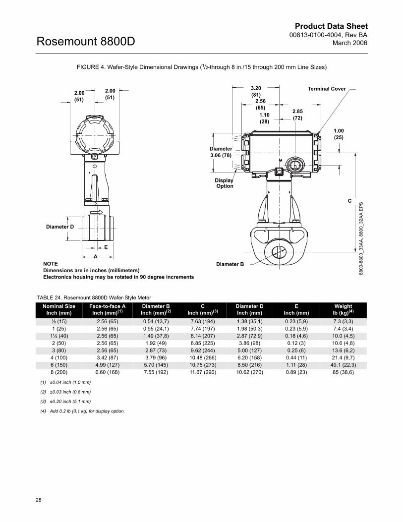
FIGURE 4. Wafer-Style Dimensional Drawings (1/2-through 8 in./15 through 200 mm Line Sizes)
2.00 (51)
2.00 (51)
E
A
Diameter D
NOTEDimensions are in inches (millimeters)Electronics housing may be rotated in 90 degree increments
Terminal Cover
Diameter B
DisplayOption
1.00 (25)
3.20 (81)
2.85 (72)
2.56 (65)
1.10 (28)
C
Diameter3.06 (78)
8800
-880
0_33
AA
, 880
0_32
AA.E
PS
TABLE 24. Rosemount 8800D Wafer-Style MeterNominal Size
Inch (mm)Face-to-face A
Inch (mm)(1)Diameter BInch (mm)(2)
CInch (mm)(3)
Diameter DInch (mm)
EInch (mm)
Weightlb (kg)(4)
½ (15) 2.56 (65) 0.54 (13,7) 7.63 (194) 1.38 (35,1) 0.23 (5,9) 7.3 (3,3)1 (25) 2.56 (65) 0.95 (24,1) 7.74 (197) 1.98 (50,3) 0.23 (5,9) 7.4 (3,4)
1½ (40) 2.56 (65) 1.49 (37,8) 8.14 (207) 2.87 (72,9) 0.18 (4,6) 10.0 (4,5)2 (50) 2.56 (65) 1.92 (49) 8.85 (225) 3.86 (98) 0.12 (3) 10.6 (4,8)3 (80) 2.56 (65) 2.87 (73) 9.62 (244) 5.00 (127) 0.25 (6) 13.6 (6,2)4 (100) 3.42 (87) 3.79 (96) 10.48 (266) 6.20 (158) 0.44 (11) 21.4 (9,7)6 (150) 4.99 (127) 5.70 (145) 10.75 (273) 8.50 (216) 1.11 (28) 49.1 (22,3)8 (200) 6.60 (168) 7.55 (192) 11.67 (296) 10.62 (270) 0.89 (23) 85 (38,6)
(1) ±0.04 inch (1.0 mm)
(2) ±0.03 inch (0.8 mm)
(3) ±0.20 inch (5.1 mm)
(4) Add 0.2 lb (0,1 kg) for display option.
28
Product Data Sheet00813-0100-4004, Rev BAMarch 2006 Rosemount 8800D
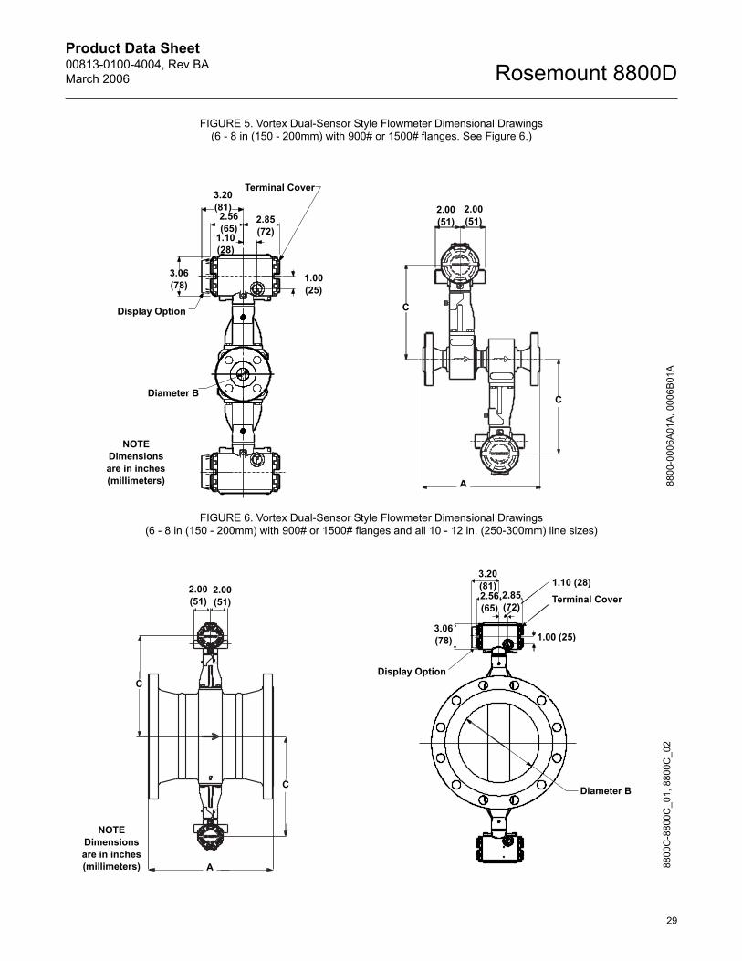
FIGURE 5. Vortex Dual-Sensor Style Flowmeter Dimensional Drawings (6 - 8 in (150 - 200mm) with 900# or 1500# flanges. See Figure 6.)
FIGURE 6. Vortex Dual-Sensor Style Flowmeter Dimensional Drawings (6 - 8 in (150 - 200mm) with 900# or 1500# flanges and all 10 - 12 in. (250-300mm) line sizes)
3.20 (81)2.56 (65)
1.10 (28)
3.06 (78)
2.85 (72)
NOTE Dimensions are in inches (millimeters)
Diameter B
1.00 (25)
Display Option
Terminal Cover
2.00 (51)
2.00 (51)
C
C
A 8800
-000
6A01
A, 0
006B
01A
NOTE Dimensions are in inches (millimeters) A
C
C
2.00 (51)
2.00 (51)
8800
C-8
800C
_01,
880
0C_0
2
Diameter B
1.00 (25)
Display Option
Terminal Cover2.85 (72)
1.10 (28)2.56 (65)
3.20 (81)
3.06 (78)
29
Product Data Sheet00813-0100-4004, Rev BA
March 2006Rosemount 8800D
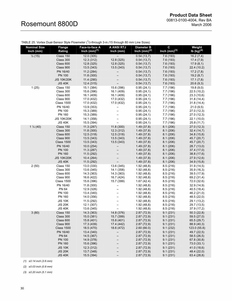
TABLE 25. Vortex Dual-Sensor Style Flowmeter (1/2-through 3-in./15 through 80 mm Line Sizes)Nominal Size
Inch (mm)FlangeRating
Face-to-face A Inch (mm)(1)
A ANSI RTJInch (mm)
Diameter B Inch (mm)(2)
C Inch (mm)(3)
Weightlb (kg)(4)
½ (15) Class 150Class 300Class 600Class 900
12.0 (305)12.3 (312)12.8 (325)13.5 (343)
–12.8 (325)12.8 (325)13.5 (343)
0.54 (13,7)0.54 (13,7)0.54 (13,7)0.54 (13,7)
7.6 (193)7.6 (193)7.6 (193)7.6 (193)
16.2 (7,4)17.4 (7,9)17.9 (8,1)
22.4 (10.2)PN 16/40PN 100
11.2 (284)11.8 (300)
––
0.54 (13,7)0.54 (13,7)
7.6 (193)7.6 (193)
17.2 (7,8)19.2 (8,7)
JIS 10K/20KJIS 40K
11.4 (290)12.4 (315)
––
0.54 (13,7)0.54 (13,7)
7.6 (193)7.6 (193)
17.1 (7,8)20.6 (9,3)
1 (25) Class 150Class 300Class 600Class 900
Class 1500
15.1 (384)15.6 (396)16.1 (409)17.0 (432)17.0 (432)
15.6 (396)16.1 (409)16.1 (409)17.0 (432)17.0 (432)
0.95 (24,1)0.95 (24,1)0.95 (24,1)0.95 (24,1)0.95 (24,1)
7.7 (196)7.7 (196)7.7 (196)7.7 (196)7.7 (196)
19.8 (9,0)22.5 (10,2)23.3 (10,6)31.8 (14,4)31.8 (14,4)
PN 16/40PN 100PN 160
13.9 (353)15.3 (389)15.3 (389)
–––
0.95 (24,1)0.95 (24,1)0.95 (24,1)
7.7 (196)7.7 (196)7.7 (196)
21.0 (9,5)27.0 (12,3)27.0 (12,3)
JIS 10K/20KJIS 40K
14.1 (358)15.5 (394)
––
0.95 (24,1)0.95 (24,1)
7.7 (196)7.7 (196)
22.1 (10,0)25.8 (11,7)
1 ½ (40) Class 150Class 300Class 600Class 900
Class 1500
11.3 (287)11.8 (300)12.5 (318)13.5 (343)13.5 (343)
11.8 (300)12.3 (312)12.5 (318)13.5 (343)13.5 (343)
1.49 (37,8)1.49 (37,8)1.49 (37,8)1.49 (37,8)1.49 (37,8)
8.1 (206)8.1 (206)8.1 (206)8.1 (206)8.1 (206)
27.0 (12,3)32.4 (14,7)34.8 (15,8)45.7 (20,7)45.7 (20,7)
PN 16/40PN 100PN 160
10.0 (254)11.3 (287)11.5 (292)
–––
1.49 (37,8)1.49 (37,8)1.49 (37,8)
8.1 (206)8.1 (206)8.1 (206)
28.7 (13,0)37.4 (17,0)38.8 (17,6)
JIS 10K/20KJIS 40K
10.4 (264)11.5 (292)
––
1.49 (37,8)1.49 (37,8)
8.1 (206)8.1 (206)
27.9 (12,6)34.9 (15,8)
2 (50) Class 150Class 300Class 600Class 900
Class 1500
13.0 (330)13.6 (345)14.3 (363)16.6 (422)15.6 (396)
13.6 (345)14.1 (358)14.3 (363)16.7 (424)15.7 (399)
1.92 (48,8)1.92 (48,8)1.92 (48,8)1.92 (48,8)1.67 (42.4)
8.5 (216)8.5 (216)8.5 (216)8.5 (216)8.5 (216)
31.9 (14,5)35.9 (16,3)39.5 (17,9)69.2 (31,4)72.0 (32.6)
PN 16/40PN 64
PN 100PN 160
11.8 (300)12.9 (328)13.4 (340)14.0 (356)
––––
1.92 (48,8)1.92 (48,8)1.92 (48,8)1.92 (48,8)
8.5 (216)8.5 (216)8.5 (216)8.5 (216)
32.9 (14,9)40.5 (18,4)46.2 (21,0)48.5 (22,0)
JIS 10KJIS 20KJIS 40K
11.5 (292)12.1 (307)13.6 (345)
–––
1.92 (48,8)1.92 (48,8)1.92 (48,8)
8.5 (216)8.5 (216)8.5 (216)
29.1 (13,2)29.7 (13,5)37.9 (17,2)
3 (80) Class 150Class 300Class 600Class 900
Class 1500
14.3 (363)15.0 (381)15.8 (401)17.3 (439)18.5 (470)
14.8 (376)15.7 (399)15.8 (401)17.4 (442)18.6 (472)
2.87 (72,9)2.87 (72,9)2.87 (72,9)2.87 (72,9)2.60 (66.0)
9.1 (231)9.1 (231)9.1 (231)9.1 (231)9.1 (232)
50.3 (22,8)59.5 (27,0)65.5 (29,7)88.9 (40,3)
123.0 (55.8)PN 16/40
PN 64PN 100PN 160
13.4 (340)14.5 (367)14.9 (378)15.6 (396)
––––
2.87 (72,9)2.87 (72,9)2.87 (72,9)2.87 (72,9)
9.1 (231)9.1 (231)9.1 (231)9.1 (231)
49.7 (22,5)58.5 (26,5)67.8 (30,8)73.0 (33,1)
JIS 10KJIS 20KJIS 40K
12.3 (312)13.7 (348)15.5 (394)
–––
2.87 (72,9)2.87 (72,9)2.87 (72,9)
9.1 (231)9.1 (231)9.1 (231)
41.0 (18,6)48.4 (22,0)63.4 (28,8)
(1) ±0.14 inch (3.6 mm)
(2) ±0.03 inch (0.8 mm)
(3) ±0.20 inch (5.1 mm)
30
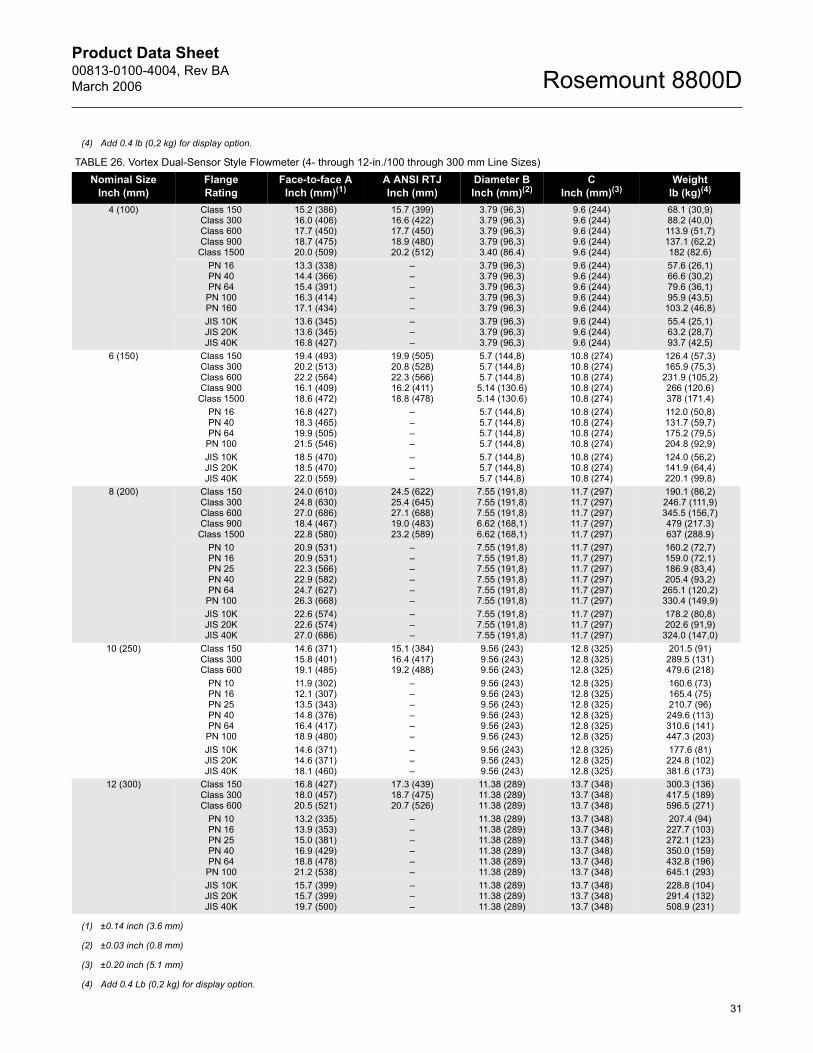
Product Data Sheet00813-0100-4004, Rev BAMarch 2006 Rosemount 8800D
(4) Add 0.4 lb (0,2 kg) for display option.
TABLE 26. Vortex Dual-Sensor Style Flowmeter (4- through 12-in./100 through 300 mm Line Sizes)Nominal Size
Inch (mm)FlangeRating
Face-to-face A Inch (mm)(1)
A ANSI RTJInch (mm)
Diameter B Inch (mm)(2)
C Inch (mm)(3)
Weightlb (kg)(4)
4 (100) Class 150Class 300Class 600Class 900Class 1500
15.2 (386)16.0 (406)17.7 (450)18.7 (475)20.0 (509)
15.7 (399)16.6 (422)17.7 (450)18.9 (480)20.2 (512)
3.79 (96,3)3.79 (96,3)3.79 (96,3)3.79 (96,3)3.40 (86.4)
9.6 (244)9.6 (244)9.6 (244)9.6 (244)9.6 (244)
68.1 (30,9)88.2 (40,0)113.9 (51,7)137.1 (62,2)182 (82.6)
PN 16PN 40PN 64PN 100PN 160
13.3 (338)14.4 (366)15.4 (391)16.3 (414)17.1 (434)
–––––
3.79 (96,3)3.79 (96,3)3.79 (96,3)3.79 (96,3)3.79 (96,3)
9.6 (244)9.6 (244)9.6 (244)9.6 (244)9.6 (244)
57.6 (26,1)66.6 (30,2)79.6 (36,1)95.9 (43,5)103.2 (46,8)
JIS 10KJIS 20KJIS 40K
13.6 (345)13.6 (345)16.8 (427)
–––
3.79 (96,3)3.79 (96,3)3.79 (96,3)
9.6 (244)9.6 (244)9.6 (244)
55.4 (25,1)63.2 (28,7)93.7 (42,5)
6 (150) Class 150Class 300Class 600Class 900Class 1500
19.4 (493)20.2 (513)22.2 (564)16.1 (409)18.6 (472)
19.9 (505)20.8 (528)22.3 (566)16.2 (411)18.8 (478)
5.7 (144,8)5.7 (144,8)5.7 (144,8)5.14 (130.6)5.14 (130.6)
10.8 (274)10.8 (274)10.8 (274)10.8 (274)10.8 (274)
126.4 (57,3)165.9 (75,3)
231.9 (105,2)266 (120.6)378 (171.4)
PN 16PN 40PN 64PN 100
16.8 (427)18.3 (465)19.9 (505)21.5 (546)
––––
5.7 (144,8)5.7 (144,8)5.7 (144,8)5.7 (144,8)
10.8 (274)10.8 (274)10.8 (274)10.8 (274)
112.0 (50,8)131.7 (59,7)175.2 (79,5)204.8 (92,9)
JIS 10KJIS 20KJIS 40K
18.5 (470)18.5 (470)22.0 (559)
–––
5.7 (144,8)5.7 (144,8)5.7 (144,8)
10.8 (274)10.8 (274)10.8 (274)
124.0 (56,2)141.9 (64,4)220.1 (99,8)
8 (200) Class 150Class 300Class 600Class 900Class 1500
24.0 (610)24.8 (630)27.0 (686)18.4 (467)22.8 (580)
24.5 (622)25.4 (645)27.1 (688)19.0 (483)23.2 (589)
7.55 (191,8)7.55 (191,8)7.55 (191,8)6.62 (168,1)6.62 (168,1)
11.7 (297)11.7 (297)11.7 (297)11.7 (297)11.7 (297)
190.1 (86,2)246.7 (111,9)345.5 (156,7)479 (217.3)637 (288.9)
PN 10PN 16PN 25PN 40PN 64PN 100
20.9 (531)20.9 (531)22.3 (566)22.9 (582)24.7 (627)26.3 (668)
––––––
7.55 (191,8)7.55 (191,8)7.55 (191,8)7.55 (191,8)7.55 (191,8)7.55 (191,8)
11.7 (297)11.7 (297)11.7 (297)11.7 (297)11.7 (297)11.7 (297)
160.2 (72,7)159.0 (72,1)186.9 (83,4)205.4 (93,2)
265.1 (120,2)330.4 (149,9)
JIS 10KJIS 20KJIS 40K
22.6 (574)22.6 (574)27.0 (686)
–––
7.55 (191,8)7.55 (191,8)7.55 (191,8)
11.7 (297)11.7 (297)11.7 (297)
178.2 (80,8)202.6 (91,9)
324.0 (147,0)10 (250) Class 150
Class 300Class 600
14.6 (371)15.8 (401)19.1 (485)
15.1 (384)16.4 (417)19.2 (488)
9.56 (243)9.56 (243)9.56 (243)
12.8 (325)12.8 (325)12.8 (325)
201.5 (91)289.5 (131)479.6 (218)
PN 10PN 16PN 25PN 40PN 64PN 100
11.9 (302)12.1 (307)13.5 (343)14.8 (376)16.4 (417)18.9 (480)
––––––
9.56 (243)9.56 (243)9.56 (243)9.56 (243)9.56 (243)9.56 (243)
12.8 (325)12.8 (325)12.8 (325)12.8 (325)12.8 (325)12.8 (325)
160.6 (73)165.4 (75)210.7 (96)249.6 (113)310.6 (141)447.3 (203)
JIS 10KJIS 20KJIS 40K
14.6 (371)14.6 (371)18.1 (460)
–––
9.56 (243)9.56 (243)9.56 (243)
12.8 (325)12.8 (325)12.8 (325)
177.6 (81)224.8 (102)381.6 (173)
12 (300) Class 150Class 300Class 600
16.8 (427)18.0 (457)20.5 (521)
17.3 (439)18.7 (475)20.7 (526)
11.38 (289)11.38 (289)11.38 (289)
13.7 (348)13.7 (348)13.7 (348)
300.3 (136)417.5 (189)596.5 (271)
PN 10PN 16PN 25PN 40PN 64PN 100
13.2 (335)13.9 (353)15.0 (381)16.9 (429)18.8 (478)21.2 (538)
––––––
11.38 (289)11.38 (289)11.38 (289)11.38 (289)11.38 (289)11.38 (289)
13.7 (348)13.7 (348)13.7 (348)13.7 (348)13.7 (348)13.7 (348)
207.4 (94)227.7 (103)272.1 (123)350.0 (159)432.8 (196)645.1 (293)
JIS 10KJIS 20KJIS 40K
15.7 (399)15.7 (399)19.7 (500)
–––
11.38 (289)11.38 (289)11.38 (289)
13.7 (348)13.7 (348)13.7 (348)
228.8 (104)291.4 (132)508.9 (231)
(1) ±0.14 inch (3.6 mm)
(2) ±0.03 inch (0.8 mm)
(3) ±0.20 inch (5.1 mm)
(4) Add 0.4 Lb (0,2 kg) for display option.
31
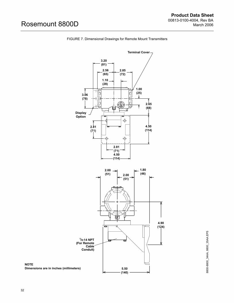
Product Data Sheet00813-0100-4004, Rev BA
March 2006Rosemount 8800D
FIGURE 7. Dimensional Drawings for Remote Mount Transmitters
3.20 (81)
2.56 (65)
1.10 (28)
2.85 (72)
1.00 (25)
2.65 (68)
4.50 (114)
2.81 (71)4.50 (114)
3.06 (78)
2.81 (71)
Display Option
Terminal Cover
4.90 (124)
5.50 (140)
1/2-14 NPT(For Remote
CableConduit)
2.00 (51) 2.00
(51)
1.80 (46)
8800
-880
0_34
AA
, 880
0_35
AA.E
PS
NOTEDimensions are in inches (millimeters)
32
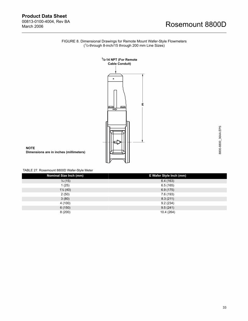
Product Data Sheet00813-0100-4004, Rev BAMarch 2006 Rosemount 8800D
FIGURE 8. Dimensional Drawings for Remote Mount Wafer-Style Flowmeters (1/2-through 8-inch/15 through 200 mm Line Sizes)
E
NOTEDimensions are in inches (millimeters)
1/2-14 NPT (For Remote Cable Conduit)
8800
-880
0_36
AA
.E88
00-8
800_
36A
A.E
PS
TABLE 27. Rosemount 8800D Wafer-Style MeterNominal Size Inch (mm) E Wafer Style Inch (mm)
½ (15) 6.4 (163)1 (25) 6.5 (165)
1½ (40) 6.9 (175)2 (50) 7.6 (193)3 (80) 8.3 (211)
4 (100) 9.2 (234)6 (150) 9.5 (241)8 (200) 10.4 (264)
33
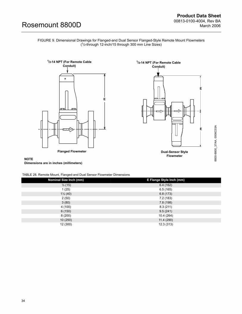
Product Data Sheet00813-0100-4004, Rev BA
March 2006Rosemount 8800D
FIGURE 9. Dimensional Drawings for Flanged-and Dual Sensor Flanged-Style Remote Mount Flowmeters (1/2-through 12-inch/15 through 300 mm Line Sizes)
1/2-14 NPT (For Remote Cable Conduit)
Flanged Flowmeter
NOTEDimensions are in inches (millimeters)
E
1/2-14 NPT (For Remote Cable Conduit)
Dual-Sensor Style Flowmeter
E
E
8800
-880
0_37
AA, 0
006C
03A
TABLE 28. Remote Mount, Flanged-and Dual Sensor Flowmeter DimensionsNominal Size Inch (mm) E Flange Style Inch (mm)
½ (15) 6.4 (162)1 (25) 6.5 (165)
1½ (40) 6.8 (173)2 (50) 7.2 (183)3 (80) 7.8 (198)4 (100) 8.3 (211)6 (150) 9.5 (241)8 (200) 10.4 (264)
10 (250) 11.4 (290)12 (300) 12.3 (313)
34
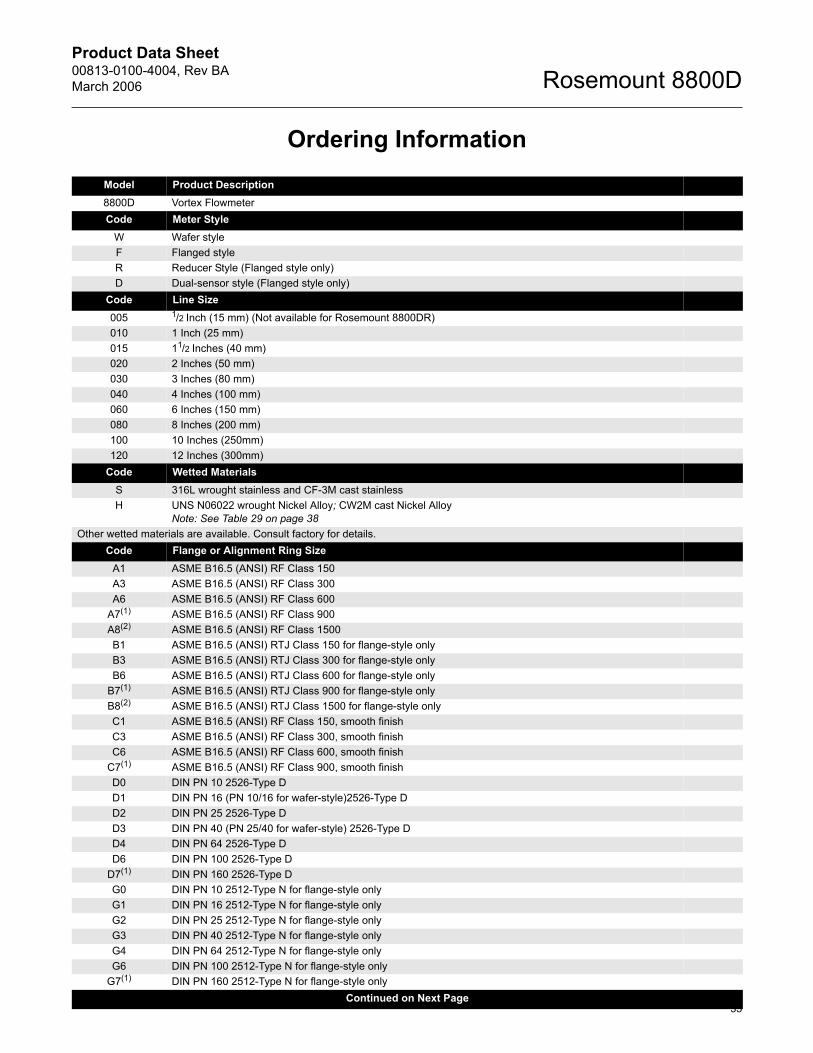
Product Data Sheet00813-0100-4004, Rev BAMarch 2006 Rosemount 8800D
35
Ordering InformationModel Product Description8800D Vortex FlowmeterCode Meter Style
W Wafer styleF Flanged styleR Reducer Style (Flanged style only)D Dual-sensor style (Flanged style only)
Code Line Size005 1/2 Inch (15 mm) (Not available for Rosemount 8800DR)010 1 Inch (25 mm)015 11/2 Inches (40 mm)020 2 Inches (50 mm)030 3 Inches (80 mm)040 4 Inches (100 mm)060 6 Inches (150 mm)080 8 Inches (200 mm)100 10 Inches (250mm)120 12 Inches (300mm)
Code Wetted MaterialsS 316L wrought stainless and CF-3M cast stainlessH UNS N06022 wrought Nickel Alloy; CW2M cast Nickel Alloy
Note: See Table 29 on page 38Other wetted materials are available. Consult factory for details.
Code Flange or Alignment Ring SizeA1 ASME B16.5 (ANSI) RF Class 150A3 ASME B16.5 (ANSI) RF Class 300A6 ASME B16.5 (ANSI) RF Class 600
A7(1) ASME B16.5 (ANSI) RF Class 900A8(2) ASME B16.5 (ANSI) RF Class 1500B1 ASME B16.5 (ANSI) RTJ Class 150 for flange-style onlyB3 ASME B16.5 (ANSI) RTJ Class 300 for flange-style onlyB6 ASME B16.5 (ANSI) RTJ Class 600 for flange-style only
B7(1) ASME B16.5 (ANSI) RTJ Class 900 for flange-style onlyB8(2) ASME B16.5 (ANSI) RTJ Class 1500 for flange-style onlyC1 ASME B16.5 (ANSI) RF Class 150, smooth finishC3 ASME B16.5 (ANSI) RF Class 300, smooth finishC6 ASME B16.5 (ANSI) RF Class 600, smooth finish
C7(1) ASME B16.5 (ANSI) RF Class 900, smooth finishD0 DIN PN 10 2526-Type DD1 DIN PN 16 (PN 10/16 for wafer-style)2526-Type DD2 DIN PN 25 2526-Type DD3 DIN PN 40 (PN 25/40 for wafer-style) 2526-Type DD4 DIN PN 64 2526-Type DD6 DIN PN 100 2526-Type D
D7(1) DIN PN 160 2526-Type DG0 DIN PN 10 2512-Type N for flange-style onlyG1 DIN PN 16 2512-Type N for flange-style onlyG2 DIN PN 25 2512-Type N for flange-style onlyG3 DIN PN 40 2512-Type N for flange-style onlyG4 DIN PN 64 2512-Type N for flange-style onlyG6 DIN PN 100 2512-Type N for flange-style only
G7(1) DIN PN 160 2512-Type N for flange-style onlyContinued on Next Page
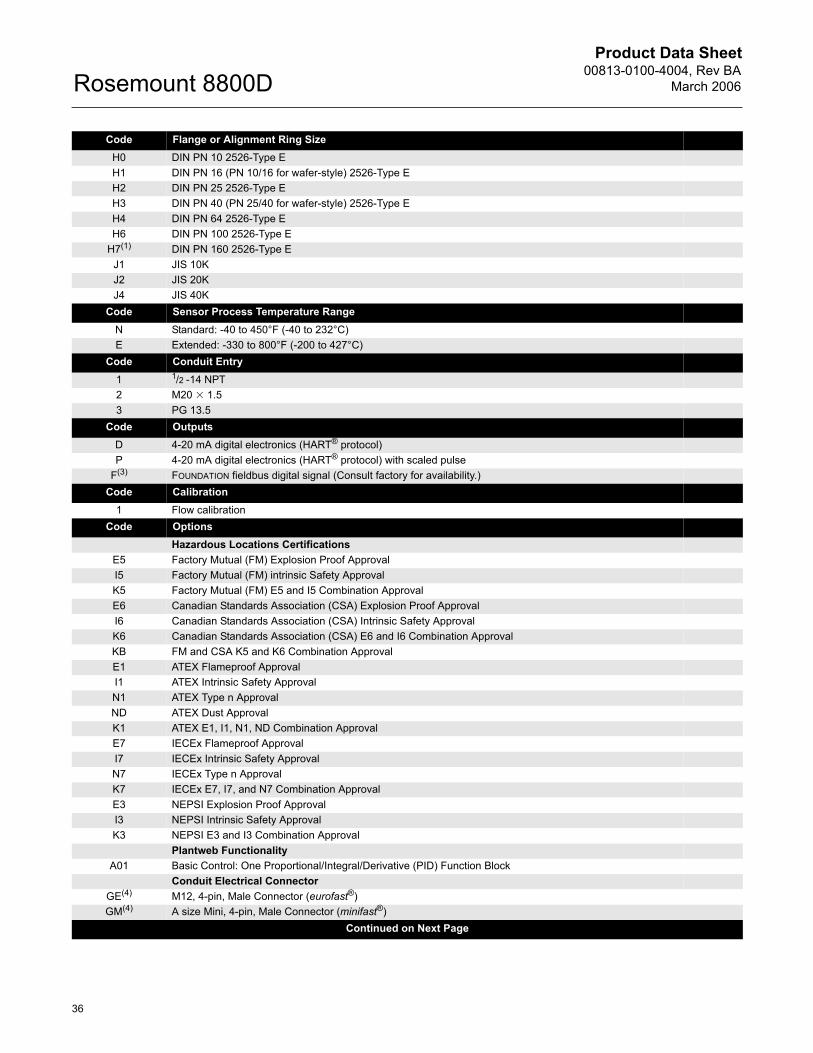
Product Data Sheet00813-0100-4004, Rev BA
March 2006Rosemount 8800D
Code Flange or Alignment Ring SizeH0 DIN PN 10 2526-Type EH1 DIN PN 16 (PN 10/16 for wafer-style) 2526-Type EH2 DIN PN 25 2526-Type EH3 DIN PN 40 (PN 25/40 for wafer-style) 2526-Type EH4 DIN PN 64 2526-Type EH6 DIN PN 100 2526-Type E
H7(1) DIN PN 160 2526-Type EJ1 JIS 10KJ2 JIS 20KJ4 JIS 40K
Code Sensor Process Temperature RangeN Standard: -40 to 450°F (-40 to 232°C)E Extended: -330 to 800°F (-200 to 427°C)
Code Conduit Entry1 1/2 -14 NPT2 M20 � 1.53 PG 13.5
Code OutputsD 4-20 mA digital electronics (HART® protocol)P 4-20 mA digital electronics (HART® protocol) with scaled pulse
F(3) FOUNDATION fieldbus digital signal (Consult factory for availability.)Code Calibration
1 Flow calibrationCode Options
Hazardous Locations CertificationsE5 Factory Mutual (FM) Explosion Proof ApprovalI5 Factory Mutual (FM) intrinsic Safety ApprovalK5 Factory Mutual (FM) E5 and I5 Combination ApprovalE6 Canadian Standards Association (CSA) Explosion Proof ApprovalI6 Canadian Standards Association (CSA) Intrinsic Safety ApprovalK6 Canadian Standards Association (CSA) E6 and I6 Combination ApprovalKB FM and CSA K5 and K6 Combination ApprovalE1 ATEX Flameproof ApprovalI1 ATEX Intrinsic Safety ApprovalN1 ATEX Type n ApprovalND ATEX Dust ApprovalK1 ATEX E1, I1, N1, ND Combination ApprovalE7 IECEx Flameproof ApprovalI7 IECEx Intrinsic Safety ApprovalN7 IECEx Type n ApprovalK7 IECEx E7, I7, and N7 Combination ApprovalE3 NEPSI Explosion Proof ApprovalI3 NEPSI Intrinsic Safety ApprovalK3 NEPSI E3 and I3 Combination Approval
Plantweb FunctionalityA01 Basic Control: One Proportional/Integral/Derivative (PID) Function Block
Conduit Electrical ConnectorGE(4) M12, 4-pin, Male Connector (eurofast®) GM(4) A size Mini, 4-pin, Male Connector (minifast®)
Continued on Next Page
36

Product Data Sheet00813-0100-4004, Rev BAMarch 2006 Rosemount 8800D
Options ContinuedOther Options
M5 LCD indicatorP2 Cleaning for special services
C4(5) NAMUR alarm and saturation values, high alarmCN(5) NAMUR alarm and saturation values, low alarmR10 Remote electronics with 10 ft (3,0 m) cableR20 Remote electronics with 20 ft (6,1 m) cableR30 Remote electronics with 30 ft (9,1 m) cable
RXX(6) Remote electronics with customer-specified cable length (up to 75 ft (23 m) maximum) T1 Transient protection terminal block
V5 (7) External ground screw assemblyCertification Options
Q4 Calibration data sheet per ISO 10474 3.1B and EN 10204 3.1Q8 Material traceability certification per ISO 10474 3.1B and EN 10204 3.1
Q14(8) German TRB 801 Nr.45 certification per ISO 10474 3.1B and EN 10204 3.1Q25 NACE MR0103 Certificate of Compliance
Q69(9) Inspection certificate weld examination (wafer) per ISO 10474 3.1B and EN 10204 3.1Q70 Inspection certificate weld examination (flanged) per ISO 10474 3.1B and EN 10204 3.1Q71 Inspection certification weld examination (flanged) per ISO 10474 3.1B (includes x-rays) and EN 10204 3.1
Code Quick Installation Guide (QIG) Language Options (Default is English)YA Danish QIGYB Hungarian QIGYC Czech QIGYD Dutch QIGYF French QIGYG German QIGYH Finnish QIGYI Italian QIGYN Norwegian QIGYO Polish QIGYP Portuguese QIGYR Russian QIGYS Spanish QIGYW Swedish QIG
Typical Model Number: 8800D F 020 S A1 N 1 D 1 M5
(1) Available on flanged and dual style meters from 1/2” - 8” (15-200 mm) and Reducer style meters from 1” - 6” (25-150 mm).
(2) Only available for stainless steel flange and dual style meters from 1” - 8” (25-200 mm).
(3) Includes two analog input (AI) function blocks, 1 Integrator (INT) function block, and Backup Link Active Scheduler.
(4) Not available with certain hazardous location certifications. Contact a Rosemount representative for details.
(5) NAMUR compliant operation and the alarm latch options are pre-set at the factory and cannot be changed to standard operation in the field.
(6) XX is a customer specified length in feet.
(7) V5 only available with no approval or E5, I5, K5, E6, I6, K6 and KB; it is standard with the other approvals.
(8) Q14 is not available with flange codes A7, A8, B7, B8, C7, D7, G7, H7, 10in.-12in. meters, and 8800DR Reducer Vortex.
(9) Q69 available for all Nickel Alloy C wafers and stainless steel wafers in line sizes 1/2-in. (15 mm), 6-in. (150 mm), and 8-in. (200 mm).
37
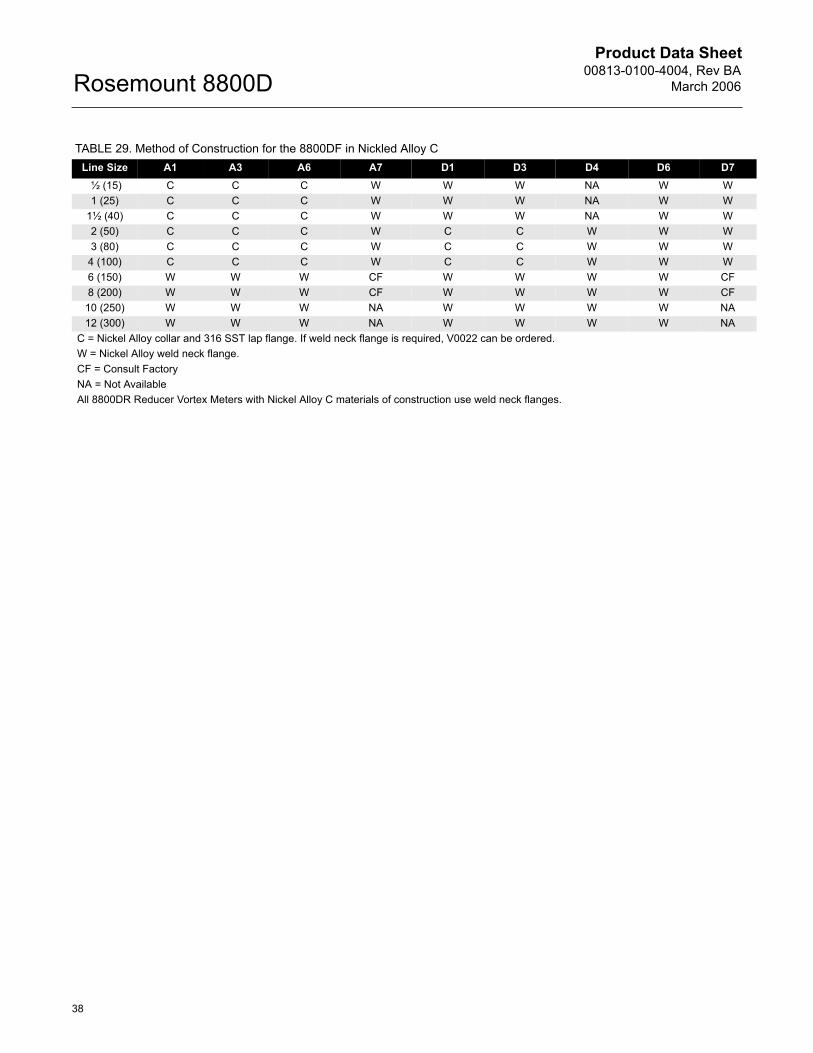
Product Data Sheet00813-0100-4004, Rev BA
March 2006Rosemount 8800D
TABLE 29. Method of Construction for the 8800DF in Nickled Alloy CLine Size A1 A3 A6 A7 D1 D3 D4 D6 D7
½ (15) C C C W W W NA W W1 (25) C C C W W W NA W W
1½ (40) C C C W W W NA W W2 (50) C C C W C C W W W3 (80) C C C W C C W W W
4 (100) C C C W C C W W W6 (150) W W W CF W W W W CF8 (200) W W W CF W W W W CF10 (250) W W W NA W W W W NA12 (300) W W W NA W W W W NA
C = Nickel Alloy collar and 316 SST lap flange. If weld neck flange is required, V0022 can be ordered.W = Nickel Alloy weld neck flange.CF = Consult FactoryNA = Not AvailableAll 8800DR Reducer Vortex Meters with Nickel Alloy C materials of construction use weld neck flanges.
38
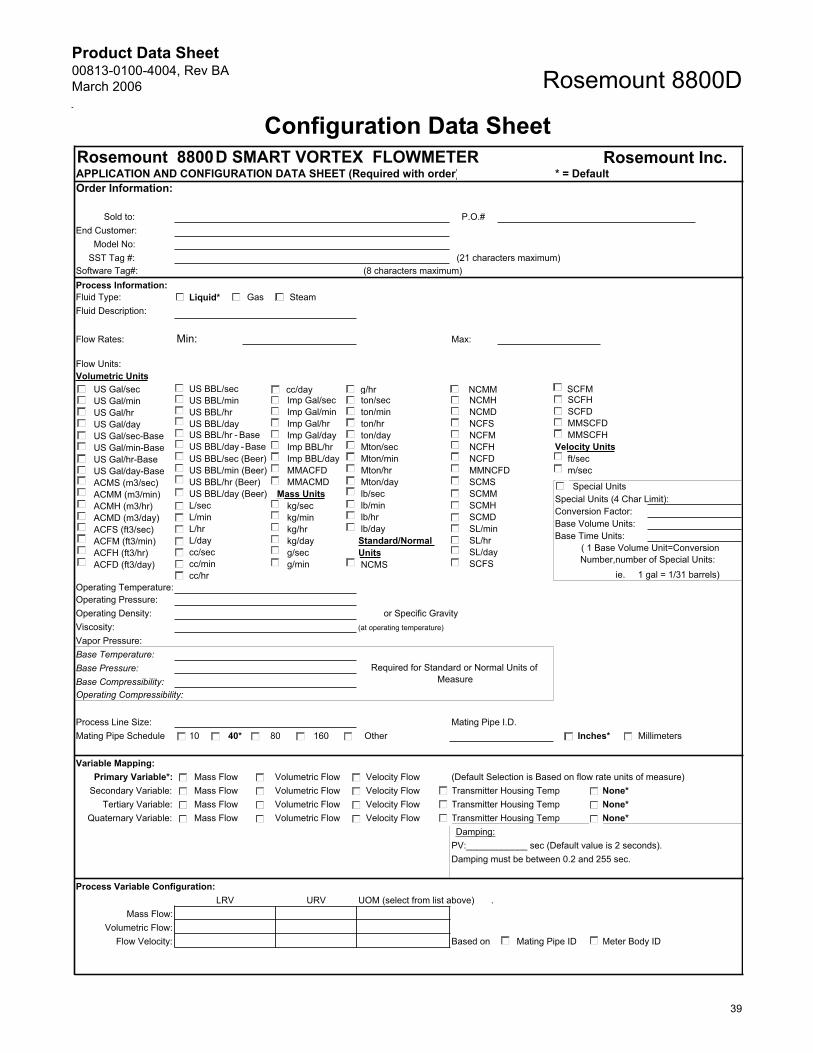
Product Data Sheet00813-0100-4004, Rev BAMarch 2006 Rosemount 8800D
Rosemount 8800 D SMART VORTEX FLOWMETER Rosemount Inc. APPLICATION AND CONFIGURATION DATA SHEET (Required with order ) * = Default Order Information:
Sold to: P.O.# End Customer: Model No: SST Tag #: (21 characters maximum) Software Tag#: (8 characters maximum) Process Information: Fluid Type: Liquid* Gas Steam Fluid Description:
Flow Rates: Min: Max:
Flow Units: Volumetric Units US Gal/sec US Gal/min US Gal/hr US Gal/day US Gal/sec-Base US Gal/min-Base US Gal/hr-Base US Gal/day-Base ACMS (m3/sec) ACMM (m3/min) ACMH (m3/hr) ACMD (m3/day) ACFS (ft3/sec) ACFM (ft3/min) ACFH (ft3/hr) ACFD (ft3/day)
US BBL/sec US BBL/min US BBL/hr US BBL/day
US BBL/sec (Beer) US BBL/min (Beer) US BBL/hr (Beer) US BBL/day (Beer) L/sec L/min L/hr L/day cc/sec cc/min cc/hr
cc/day Imp Gal/sec Imp Gal/min Imp Gal/hr Imp Gal/day Imp BBL/hr Imp BBL/day MMACFD MMACMDMass Units kg/sec kg/min kg/hr kg/day g/sec g/min
g/hr ton/sec ton/min ton/hr ton/day Mton/sec Mton/min Mton/hr Mton/day lb/sec lb/min lb/hr lb/dayStandard/NormalUnits NCMS
NCMM NCMH NCMD NCFS NCFM NCFH NCFD MMNCFD SCMS SCMM SCMH SCMD SL/min SL/hr SL/day SCFS
SCFM SCFH SCFD MMSCFD MMSCFHVelocity Units ft/sec m/sec
Special Units Special Units (4 Char Limit) : Conversion Factor: Base Volume Units: Base Time Units:
( 1 Base Volume Unit=Conversion Number,number of Special Units:
ie. 1 gal = 1/31 barrels) Operating Temperature: Operating Pressure: Operating Density: or Specific Gravity Viscosity: (at operating temperature)
Vapor Pressure: Base Temperature:
Required for Standard or Normal Units of Measure
Base Pressure: Base Compressibility: Operating Compressibility:
Process Line Size: Mating Pipe I.D. Mating Pipe Schedule 10 40* 80 160 Other Inches* Millimeters
Variable Mapping: Primary Variable*: Mass Flow Volumetric Flow Velocity Flow (Default Selection is Based on flow rate units of measure)
Secondary Variable: Mass Flow Volumetric Flow Velocity Flow Transmitter Housing Temp None* Tertiary Variable: Mass Flow Volumetric Flow Velocity Flow Transmitter Housing Temp None*
Quaternary Variable: Mass Flow Volumetric Flow Velocity Flow Transmitter Housing Temp None* Damping:
PV:____________ sec (Default value is 2 seconds) . Damping must be between 0.2 and 255 sec.
Process Variable Configuration: LRV URV UOM (select from list above) .
Mass Flow: Volumetric Flow:
Flow Velocity: Based on Mating Pipe ID Meter Body ID
US BBL/hr - Base US BBL/day - Base
Configuration Data Sheet
39
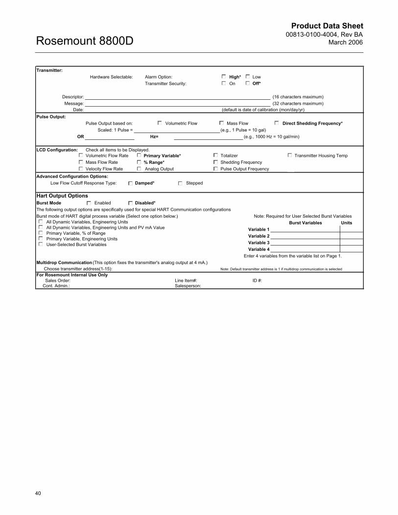
Product Data Sheet00813-0100-4004, Rev BA
March 2006Rosemount 8800D
Transmitter: Hardware Selectable: Alarm Option: High* Low
Transmitter Security: On Off*
Descriptor: (16 characters maximum) Message: (32 characters maximum)
Date: (default is date of calibration (mon/day/yr) Pulse Output:
Pulse Output based on: Volumetric Flow Mass Flow Direct Shedding Frequency* Scaled: 1 Pulse = (e.g., 1 Pulse = 10 gal)
OR Hz= (e.g., 1000 Hz = 10 gal/min)
LCD Configuration: Check all items to be Displayed. Volumetric Flow Rate Primary Variable* Totalizer Transmitter Housing Temp Mass Flow Rate % Range* Shedding Frequency Velocity Flow Rate Analog Output Pulse Output Frequency
Advanced Configuration Options: Low Flow Cutoff Response Type: Damped* Stepped
Hart Output Options Burst Mode Enabled Disabled* The following output options are specifically used for special HART Communication configurations Burst mode of HART digital process variable (Select one option below:) Note: Required for User Selected Burst Variables All Dynamic Variables, Engineering Units All Dynamic Variables, Engineering Units and PV mA Value Primary Variable, % of Range Primary Variable, Engineering Units User-Selected Burst Variables
Burst Variables Units Variable 1 Variable 2 Variable 3 Variable 4
Enter 4 variables from the variable list on Page 1. Multidrop Communication (This option fixes the transmitter's analog output at 4 mA.) Choose transmitter address(1-15) : Note: Default transmitter address is 1 if multidrop communication is selected
For Rosemount Internal Use Only Sales Order: Line Item#: ID #: Cont. Admin.: Salesperson:
40

Rosemount and the Rosemount logotype are registered trademarks of Rosemount Inc.PlantWeb is a mark of one of the Emerson Process Management companies.All other marks are the property of their respective owners.
Approved by the Committee of Russian Federation for Standardization, Metrology and Certification (the Gosstandart of Russia) and registered in the Russian State Register of measuring instruments.Reducer Vortex is a trademark of Rosemount Inc.MultiVariable (MV) is a trademark of Rosemount Inc.Annubar is a registered trademark of Dieterich Standard Inc.Mass ProBar and ProBar are trademarks of Dieterich Standard Inc.HART is a registered trademark of the HART Communication Foundation.FOUNDATION is a trademark of the Fieldbus Foundation.Cover Photo: 8800-8800k921
¢00813-0100-4004Y¤
Product Data Sheet00813-0100-4004, Rev BA
March 2006Rosemount 8800D