Embed Size (px)
Citation preview
Product Data SheetOctober 2018
00813-0100-4004, Rev KF
Rosemount™ 8800D Series Vortex Flowmeter
HART® and FOUNDATION™ Fieldbus Protocols
All welded, non-clog design provides maximum performance, reliability and enhanced safety by eliminating ports and gaskets. No seals, just steel.
CriticalProcess™ Vortex eliminates bypass piping and optimizes safety during maintenance.
SIL 2/3 Capable: IEC 61508 certified by an accredited 3rd party agency for use in safety instrumented systems up to SIL 3.
Available with optional multivariable output. Internal temperature compensation provides cost-effective saturated steam and liquid mass flow measurement.
Adaptive Digital Signal Processing (ADSP) provides vibration immunity and flow range optimization.
Reducer™ Vortex extends the measurable flow range, reduces installation costs, and minimizes project risk.
Simplified troubleshooting through device diagnostics and meter verification.
Available in wafer, flanged, dual, reducer and high pressure designs.
Rosemount 8800D October 2018
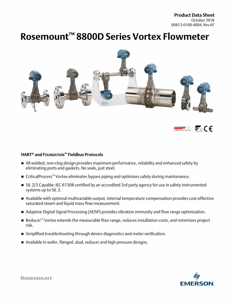
The Rosemount 8800D delivers reliability, safety, and maximum process availability
Rosemount Reliability—The Rosemount 8800D Vortex eliminates impulse lines, ports, and gaskets to improve reliability.
Non-clog Design—Unique all welded, gasket-free construction which has no ports or crevices that can clog.
SIL 2/3 Capable - The Rosemount 8800D Vortex is certified by an accredited 3rd part agency for use in safety instrumented systems up to SIL 3 (minimum requirement of single use [1oo1] for SIL 2 and redundant use [1oo2] for SIL 3).
Vibration Immunity—Mass balancing of the sensor system, and Adaptive Digital Signal Processing (ADSP) provide vibration immunity.
Replaceable Sensor—The sensor is isolated from the process and can be replaced without breaking the process seal. All line sizes use the same sensor design allowing a single spare to serve every meter.
Simplified Troubleshooting—Device Diagnostics enable field verification of meter electronics and sensor without process shutdown.
Contents
Ordering Information . . . . . . . . . . . . . . . . . . . . . . . . . . . . 8
Specifications . . . . . . . . . . . . . . . . . . . . . . . . . . . . . . . . . . . 16
Typical Flow Ranges . . . . . . . . . . . . . . . . . . . . . . . . . . . . . . 21
Product Certifications . . . . . . . . . . . . . . . . . . . . . . . . . . . . 33
Dimensional Drawings . . . . . . . . . . . . . . . . . . . . . . . . . . . . 41
2 www.emerson.com/rosemount
Rosemount 8800DOctober 2018
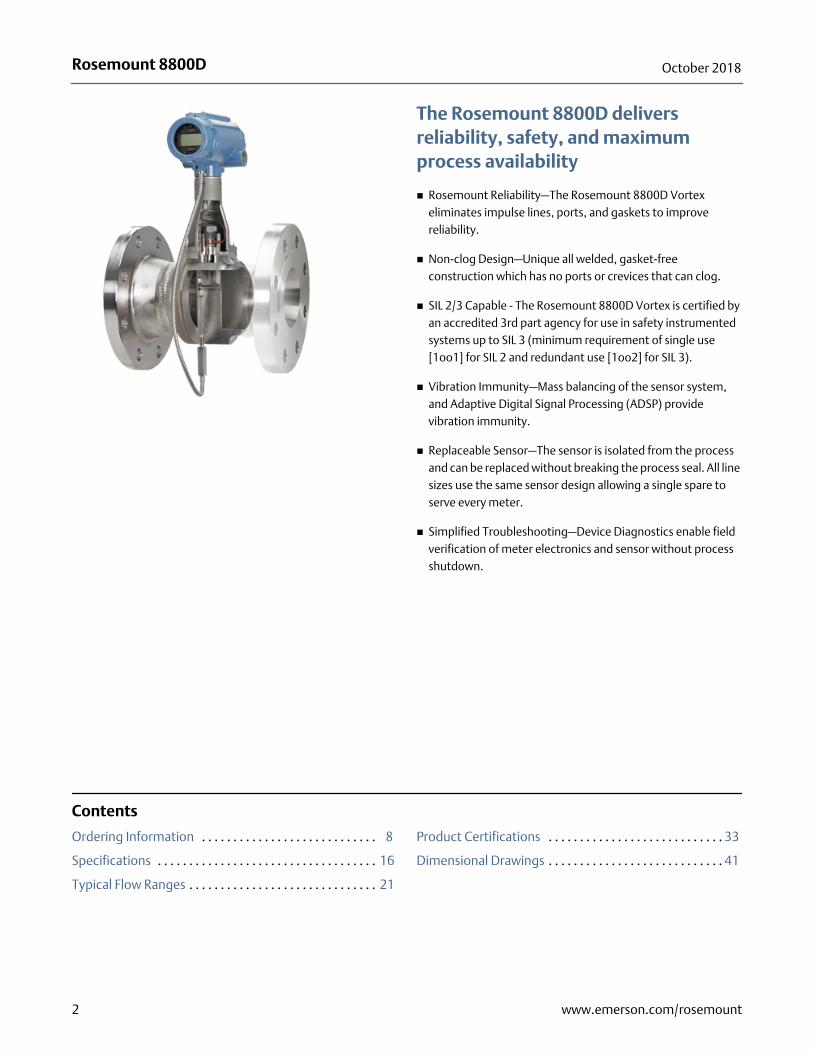
The Rosemount 8800D CriticalProcess Vortex increases process availability and enhances overall safety
Eliminate bypass piping for critical process installations
Traditional vortex installations in critical applications include a bypass line to allow process fluid to be re-directed around the vortex flow meter during routine sensor maintenance. Rosemount's unique non-wetted sensor can be installed without bypass piping, even in the most difficult process environments.
Improve process availability
Eliminate the need to shut down the process during routine maintenance and meter verification.
Enhances safety in hazardous process fluid applications
A needle valve enables access to the sensor cavity to verify that no process fluid is present.
Available in Flanged, Reducer, and Dual Vortex meter designs in 1- through 12-in. meter body sizes for ASME B16.5 flange connections.
Available in 40 mm through 300 mm meter body sizes for EN 1092-1 and JIS B2220 flange connections.
3www.emerson.com/rosemount
Rosemount 8800D October 2018
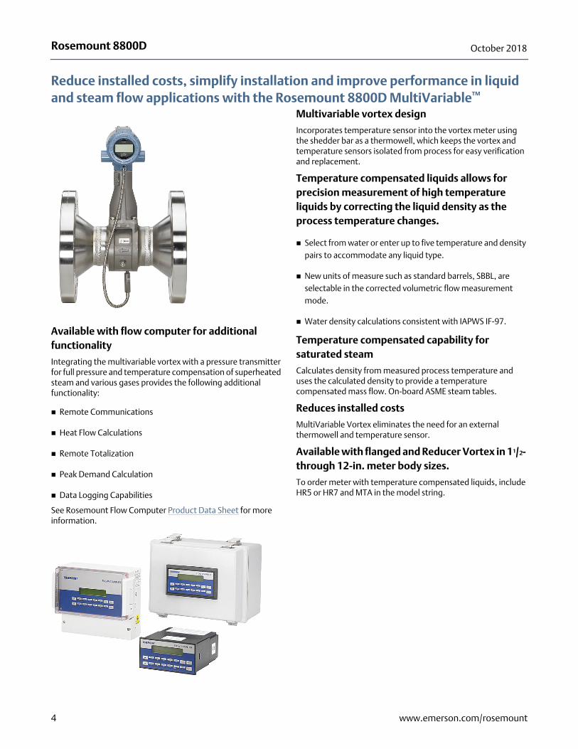
Reduce installed costs, simplify installation and improve performance in liquid and steam flow applications with the Rosemount 8800D MultiVariable™
Available with flow computer for additional functionality
Integrating the multivariable vortex with a pressure transmitter for full pressure and temperature compensation of superheated steam and various gases provides the following additional functionality:
Remote Communications
Heat Flow Calculations
Remote Totalization
Peak Demand Calculation
Data Logging Capabilities
See Rosemount Flow Computer Product Data Sheet for more information.
Multivariable vortex design
Incorporates temperature sensor into the vortex meter using the shedder bar as a thermowell, which keeps the vortex and temperature sensors isolated from process for easy verification and replacement.
Temperature compensated liquids allows for precision measurement of high temperature liquids by correcting the liquid density as the process temperature changes.
Select from water or enter up to five temperature and density pairs to accommodate any liquid type.
New units of measure such as standard barrels, SBBL, are selectable in the corrected volumetric flow measurement mode.
Water density calculations consistent with IAPWS IF-97.
Temperature compensated capability for saturated steam
Calculates density from measured process temperature and uses the calculated density to provide a temperature compensated mass flow. On-board ASME steam tables.
Reduces installed costs
MultiVariable Vortex eliminates the need for an external thermowell and temperature sensor.
Available with flanged and Reducer Vortex in 11/2- through 12-in. meter body sizes.
To order meter with temperature compensated liquids, include HR5 or HR7 and MTA in the model string.
4 www.emerson.com/rosemount
Rosemount 8800DOctober 2018
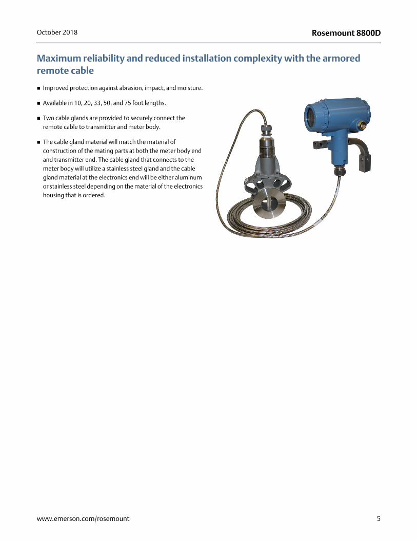
Maximum reliability and reduced installation complexity with the armored remote cable
Improved protection against abrasion, impact, and moisture.
Available in 10, 20, 33, 50, and 75 foot lengths.
Two cable glands are provided to securely connect the remote cable to transmitter and meter body.
The cable gland material will match the material of construction of the mating parts at both the meter body end and transmitter end. The cable gland that connects to the meter body will utilize a stainless steel gland and the cable gland material at the electronics end will be either aluminum or stainless steel depending on the material of the electronics housing that is ordered.
5www.emerson.com/rosemount
Rosemount 8800D October 2018
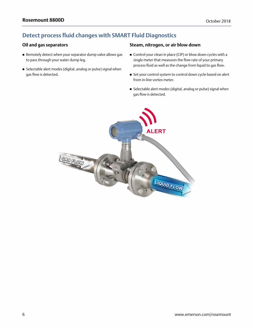
Detect process fluid changes with SMART Fluid Diagnostics
Oil and gas separators
Remotely detect when your separator dump valve allows gas to pass through your water dump leg.
Selectable alert modes (digital, analog or pulse) signal when gas flow is detected.
Steam, nitrogen, or air blow down
Control your clean in place (CIP) or blow down cycles with a single meter that measures the flow rate of your primary process fluid as well as the change from liquid to gas flow.
Set your control system to control down cycle based on alert from in-line vortex meter.
Selectable alert modes (digital, analog or pulse) signal when gas flow is detected.
6 www.emerson.com/rosemount
Rosemount 8800DOctober 2018
Rosemount 8800D Vortex Flowmeter with FOUNDATION FieldbusThe software for the Rosemount 8800D Flowmeter with FOUNDATION Fieldbus permits remote testing and configuration using any FOUNDATION Fieldbus-compliant host, such as the DeltaV™ system from Emerson™ Process Management.
Transducer block
The transducer block calculates flow from sensor frequency. The calculation includes information about damping, shedding frequency, K-factor, process fluid, pipe ID, and diagnostics.
Resource block
The resource block contains physical transmitter information, including available memory, manufacturer identification, device type, software tag, and unique identification.
Backup Link Active Scheduler (LAS)
The transmitter is classified as a device link master. A device link master can function as an LAS if the current link master device fails or is removed from the segment.
The host or other configuration tool is used to download the schedule for the application to the link master device. In the absence of a primary link master, the transmitter will claim the LAS and provide permanent control for the H1 segment.
Diagnostics
The transmitter automatically performs continuous self-diagnostics. The user can perform on-line testing of the transmitter digital signal. Advanced simulation diagnostics are available. This enables remote verification of the electronics via a flow signal generator built into the electronics. The sensor strength value can be used to view the process flow signal and provide information regarding filter settings.
FOUNDATION Fieldbus function blocks
Analog input
The AI function block processes the measurement and makes it available to other function blocks. The AI function block also allows filtering, alarming, and engineering unit changes.
The Rosemount 8800D Flowmeter with FOUNDATION Fieldbus comes with five AI function blocks. Two of the AI function blocks, flow and signal strength, come as standard. Three additional AI function blocks are available when the MTA option is selected: electronics temperature, process temperature, and process density. Note that process density is only available when the process fluid is configured as temperature compensated saturated steam, shown as TComp Sat Steam in the device.
Proportional/Integral/Derivative
The optional PID function block provides a sophisticated implementation of the universal PID algorithm. The PID function block features input for feed forward control, alarms on the process variable, and control deviation. The PID type (series or Instrument Society of America [ISA]) is user-selectable on the derivative filter.
Integrator
The standard integrator block is available for totalization of flow.
Arithmetic
The standard arithmetic block is available for various computations.
Setup
Basic setup requires connecting the transmitter to a fieldbus network or Field Communicator. The FOUNDATION Fieldbus-compliant host will automatically establish communication with the device.
The Rosemount 8800D Flowmeter can be easily configured using the DeltaV system. User-configurable parameters include:
Tag
Scaling and units
Process fluid type
Damping
Fixed process density
Pipe inside diameter (ID)(1)
Fixed process temperature(1)
Tagging information can be entered into the transmitter to allow identification and a physical description. 32-character tags are provided for identification of the transmitter and each function block.
1. Process temperature and pipe ID have known effects on the K-factor. The Rosemount 8800D software automatically accounts for these effects by compensating the K-factor.
7www.emerson.com/rosemount
Rosemount 8800D October 2018
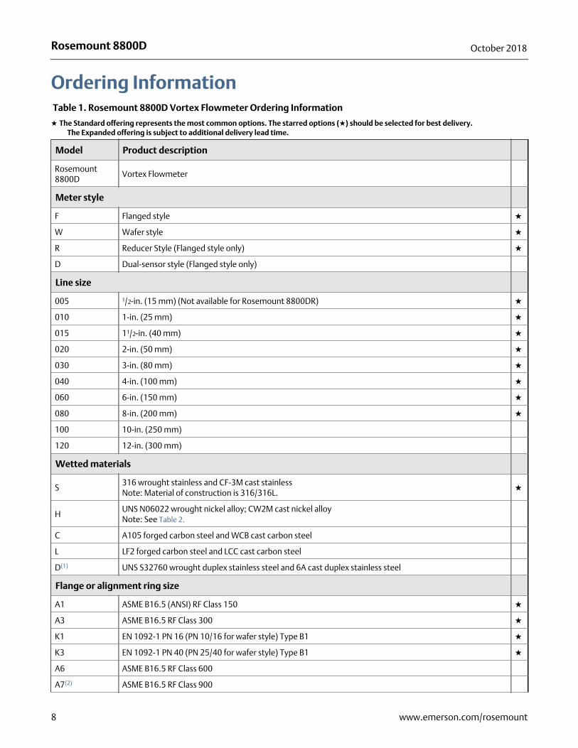
Ordering Information Table 1. Rosemount 8800D Vortex Flowmeter Ordering Information
★ The Standard offering represents the most common options. The starred options (★) should be selected for best delivery.__The Expanded offering is subject to additional delivery lead time.
Model Product description
Rosemount 8800D
Vortex Flowmeter
Meter style
F Flanged style ★
W Wafer style ★
R Reducer Style (Flanged style only) ★
D Dual-sensor style (Flanged style only)
Line size
005 1/2-in. (15 mm) (Not available for Rosemount 8800DR) ★
010 1-in. (25 mm) ★
015 11/2-in. (40 mm) ★
020 2-in. (50 mm) ★
030 3-in. (80 mm) ★
040 4-in. (100 mm) ★
060 6-in. (150 mm) ★
080 8-in. (200 mm) ★
100 10-in. (250 mm)
120 12-in. (300 mm)
Wetted materials
S316 wrought stainless and CF-3M cast stainlessNote: Material of construction is 316/316L.
★
HUNS N06022 wrought nickel alloy; CW2M cast nickel alloyNote: See Table 2.
C A105 forged carbon steel and WCB cast carbon steel
L LF2 forged carbon steel and LCC cast carbon steel
D(1) UNS S32760 wrought duplex stainless steel and 6A cast duplex stainless steel
Flange or alignment ring size
A1 ASME B16.5 (ANSI) RF Class 150 ★
A3 ASME B16.5 RF Class 300 ★
K1 EN 1092-1 PN 16 (PN 10/16 for wafer style) Type B1 ★
K3 EN 1092-1 PN 40 (PN 25/40 for wafer style) Type B1 ★
A6 ASME B16.5 RF Class 600
A7(2) ASME B16.5 RF Class 900
8 www.emerson.com/rosemount
Rosemount 8800DOctober 2018
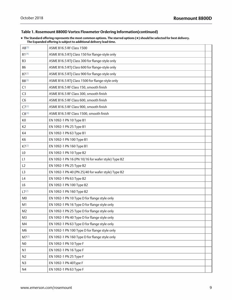
A8(3) ASME B16.5 RF Class 1500
B1(4) ASME B16.5 RTJ Class 150 for flange-style only
B3 ASME B16.5 RTJ Class 300 for flange-style only
B6 ASME B16.5 RTJ Class 600 for flange-style only
B7(2) ASME B16.5 RTJ Class 900 for flange-style only
B8(3) ASME B16.5 RTJ Class 1500 for flange-style only
C1 ASME B16.5 RF Class 150, smooth finish
C3 ASME B16.5 RF Class 300, smooth finish
C6 ASME B16.5 RF Class 600, smooth finish
C7(2) ASME B16.5 RF Class 900, smooth finish
C8(3) ASME B16.5 RF Class 1500, smooth finish
K0 EN 1092-1 PN 10 Type B1
K2 EN 1092-1 PN 25 Type B1
K4 EN 1092-1 PN 63 Type B1
K6 EN 1092-1 PN 100 Type B1
K7(2) EN 1092-1 PN 160 Type B1
L0 EN 1092-1 PN 10 Type B2
L1 EN 1092-1 PN 16 (PN 10/16 for wafer style) Type B2
L2 EN 1092-1 PN 25 Type B2
L3 EN 1092-1 PN 40 (PN 25/40 for wafer style) Type B2
L4 EN 1092-1 PN 63 Type B2
L6 EN 1092-1 PN 100 Type B2
L7(2) EN 1092-1 PN 160 Type B2
M0 EN 1092-1 PN 10 Type D for flange style only
M1 EN 1092-1 PN 16 Type D for flange style only
M2 EN 1092-1 PN 25 Type D for flange style only
M3 EN 1092-1 PN 40 Type D for flange style only
M4 EN 1092-1 PN 63 Type D for flange style only
M6 EN 1092-1 PN 100 Type D for flange style only
M7(2) EN 1092-1 PN 160 Type D for flange style only
N0 EN 1092-1 PN 10 Type F
N1 EN 1092-1 PN 16 Type F
N2 EN 1092-1 PN 25 Type F
N3 EN 1092-1 PN 40Type F
N4 EN 1092-1 PN 63 Type F
Table 1. Rosemount 8800D Vortex Flowmeter Ordering Information(continued)
★ The Standard offering represents the most common options. The starred options (★) should be selected for best delivery.__The Expanded offering is subject to additional delivery lead time.
9www.emerson.com/rosemount
Rosemount 8800D October 2018
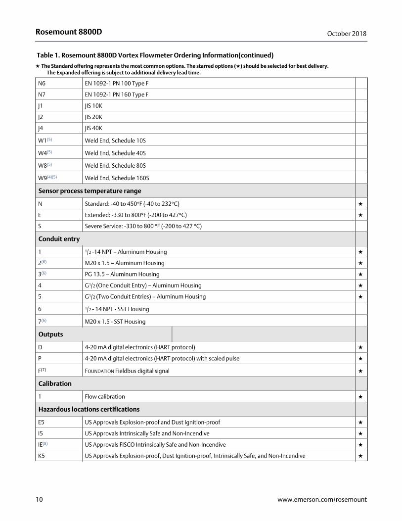
N6 EN 1092-1 PN 100 Type F
N7 EN 1092-1 PN 160 Type F
J1 JIS 10K
J2 JIS 20K
J4 JIS 40K
W1(5) Weld End, Schedule 10S
W4(5) Weld End, Schedule 40S
W8(5) Weld End, Schedule 80S
W9(4)(5) Weld End, Schedule 160S
Sensor process temperature range
N Standard: -40 to 450°F (-40 to 232°C) ★
E Extended: -330 to 800°F (-200 to 427°C) ★
S Severe Service: -330 to 800 °F (-200 to 427 °C)
Conduit entry
1 1/2 -14 NPT – Aluminum Housing ★
2(6) M20 x 1.5 – Aluminum Housing ★
3(6) PG 13.5 – Aluminum Housing ★
4 G1/2 (One Conduit Entry) – Aluminum Housing ★
5 G1/2 (Two Conduit Entries) – Aluminum Housing ★
6 1/2 - 14 NPT - SST Housing
7(6) M20 x 1.5 - SST Housing
Outputs
D 4-20 mA digital electronics (HART protocol) ★
P 4-20 mA digital electronics (HART protocol) with scaled pulse ★
F(7) FOUNDATION Fieldbus digital signal ★
Calibration
1 Flow calibration ★
Hazardous locations certifications
E5 US Approvals Explosion-proof and Dust Ignition-proof ★
I5 US Approvals Intrinsically Safe and Non-Incendive ★
IE(8) US Approvals FISCO Intrinsically Safe and Non-Incendive ★
K5 US Approvals Explosion-proof, Dust Ignition-proof, Intrinsically Safe, and Non-Incendive ★
Table 1. Rosemount 8800D Vortex Flowmeter Ordering Information(continued)
★ The Standard offering represents the most common options. The starred options (★) should be selected for best delivery.__The Expanded offering is subject to additional delivery lead time.
10 www.emerson.com/rosemount
Rosemount 8800DOctober 2018
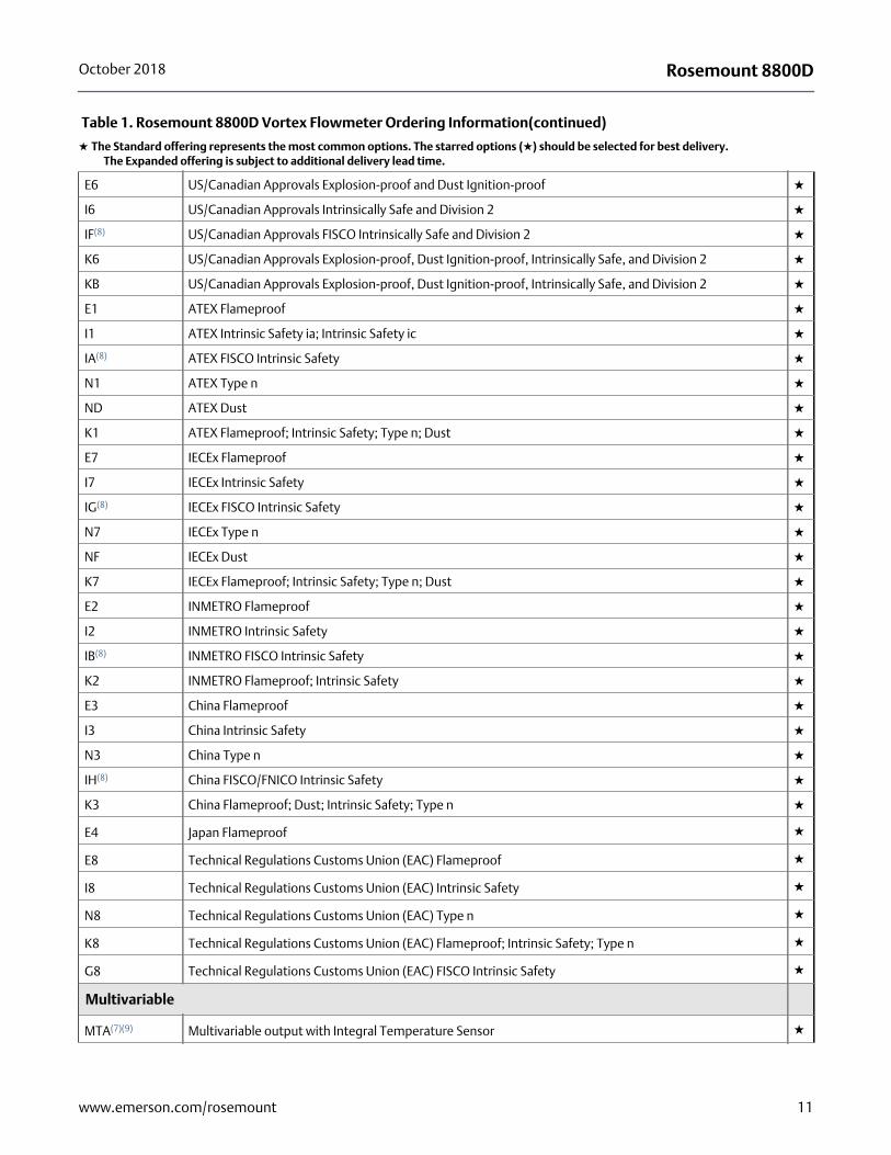
E6 US/Canadian Approvals Explosion-proof and Dust Ignition-proof ★
I6 US/Canadian Approvals Intrinsically Safe and Division 2 ★
IF(8) US/Canadian Approvals FISCO Intrinsically Safe and Division 2 ★
K6 US/Canadian Approvals Explosion-proof, Dust Ignition-proof, Intrinsically Safe, and Division 2 ★
KB US/Canadian Approvals Explosion-proof, Dust Ignition-proof, Intrinsically Safe, and Division 2 ★
E1 ATEX Flameproof ★
I1 ATEX Intrinsic Safety ia; Intrinsic Safety ic ★
IA(8) ATEX FISCO Intrinsic Safety ★
N1 ATEX Type n ★
ND ATEX Dust ★
K1 ATEX Flameproof; Intrinsic Safety; Type n; Dust ★
E7 IECEx Flameproof ★
I7 IECEx Intrinsic Safety ★
IG(8) IECEx FISCO Intrinsic Safety ★
N7 IECEx Type n ★
NF IECEx Dust ★
K7 IECEx Flameproof; Intrinsic Safety; Type n; Dust ★
E2 INMETRO Flameproof ★
I2 INMETRO Intrinsic Safety ★
IB(8) INMETRO FISCO Intrinsic Safety ★
K2 INMETRO Flameproof; Intrinsic Safety ★
E3 China Flameproof ★
I3 China Intrinsic Safety ★
N3 China Type n ★
IH(8) China FISCO/FNICO Intrinsic Safety ★
K3 China Flameproof; Dust; Intrinsic Safety; Type n ★
E4 Japan Flameproof ★
E8 Technical Regulations Customs Union (EAC) Flameproof ★
I8 Technical Regulations Customs Union (EAC) Intrinsic Safety ★
N8 Technical Regulations Customs Union (EAC) Type n ★
K8 Technical Regulations Customs Union (EAC) Flameproof; Intrinsic Safety; Type n ★
G8 Technical Regulations Customs Union (EAC) FISCO Intrinsic Safety ★
Multivariable
MTA(7)(9) Multivariable output with Integral Temperature Sensor ★
Table 1. Rosemount 8800D Vortex Flowmeter Ordering Information(continued)
★ The Standard offering represents the most common options. The starred options (★) should be selected for best delivery.__The Expanded offering is subject to additional delivery lead time.
11www.emerson.com/rosemount
Rosemount 8800D October 2018
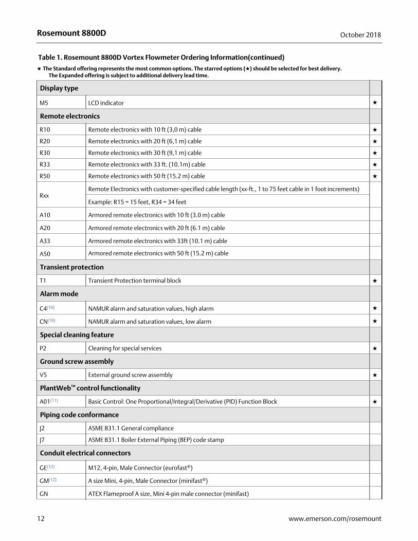
Display type
M5 LCD indicator ★
Remote electronics
R10 Remote electronics with 10 ft (3,0 m) cable ★
R20 Remote electronics with 20 ft (6,1 m) cable ★
R30 Remote electronics with 30 ft (9,1 m) cable ★
R33 Remote electronics with 33 ft. (10.1m) cable ★
R50 Remote electronics with 50 ft (15.2 m) cable ★
RxxRemote Electronics with customer-specified cable length (xx-ft., 1 to 75 feet cable in 1 foot increments)
Example: R15 = 15 feet, R34 = 34 feet
A10 Armored remote electronics with 10 ft (3.0 m) cable
A20 Armored remote electronics with 20 ft (6.1 m) cable
A33 Armored remote electronics with 33ft (10.1 m) cable
A50 Armored remote electronics with 50 ft (15.2 m) cable
Transient protection
T1 Transient Protection terminal block ★
Alarm mode
C4(10) NAMUR alarm and saturation values, high alarm ★
CN(10) NAMUR alarm and saturation values, low alarm ★
Special cleaning feature
P2 Cleaning for special services ★
Ground screw assembly
V5 External ground screw assembly ★
PlantWeb™ control functionality
A01(11) Basic Control: One Proportional/Integral/Derivative (PID) Function Block ★
Piping code conformance
J2 ASME B31.1 General compliance
J7 ASME B31.1 Boiler External Piping (BEP) code stamp
Conduit electrical connectors
GE(12) M12, 4-pin, Male Connector (eurofast®)
GM(12) A size Mini, 4-pin, Male Connector (minifast®)
GN ATEX Flameproof A size, Mini 4-pin male connector (minifast)
Table 1. Rosemount 8800D Vortex Flowmeter Ordering Information(continued)
★ The Standard offering represents the most common options. The starred options (★) should be selected for best delivery.__The Expanded offering is subject to additional delivery lead time.
12 www.emerson.com/rosemount
Rosemount 8800DOctober 2018
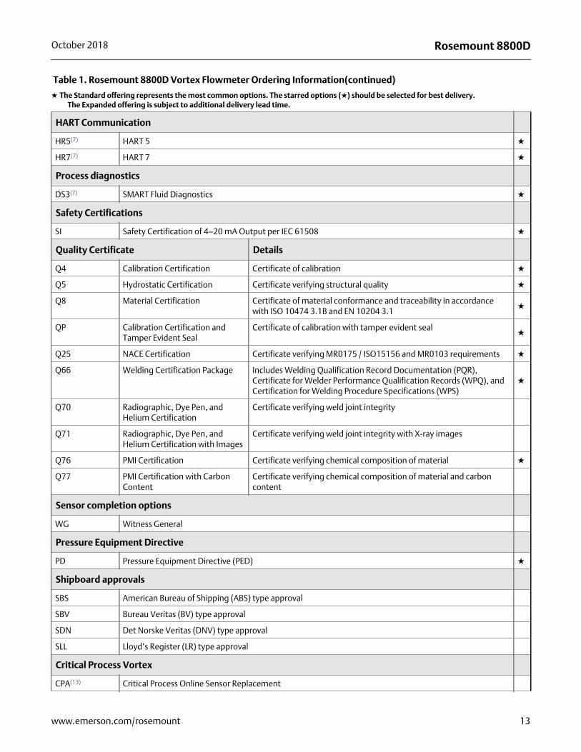
HART Communication
HR5(7) HART 5 ★
HR7(7) HART 7 ★
Process diagnostics
DS3(7) SMART Fluid Diagnostics ★
Safety Certifications
SI Safety Certification of 4–20 mA Output per IEC 61508 ★
Quality Certificate Details
Q4 Calibration Certification Certificate of calibration ★
Q5 Hydrostatic Certification Certificate verifying structural quality ★
Q8 Material Certification Certificate of material conformance and traceability in accordance with ISO 10474 3.1B and EN 10204 3.1
★
QP Calibration Certification and Tamper Evident Seal
Certificate of calibration with tamper evident seal★
Q25 NACE Certification Certificate verifying MR0175 / ISO15156 and MR0103 requirements ★
Q66 Welding Certification Package Includes Welding Qualification Record Documentation (PQR), Certificate for Welder Performance Qualification Records (WPQ), and Certification for Welding Procedure Specifications (WPS)
★
Q70 Radiographic, Dye Pen, and Helium Certification
Certificate verifying weld joint integrity
Q71 Radiographic, Dye Pen, and Helium Certification with Images
Certificate verifying weld joint integrity with X-ray images
Q76 PMI Certification Certificate verifying chemical composition of material ★
Q77 PMI Certification with Carbon Content
Certificate verifying chemical composition of material and carbon content
Sensor completion options
WG Witness General
Pressure Equipment Directive
PD Pressure Equipment Directive (PED) ★
Shipboard approvals
SBS American Bureau of Shipping (ABS) type approval
SBV Bureau Veritas (BV) type approval
SDN Det Norske Veritas (DNV) type approval
SLL Lloyd’s Register (LR) type approval
Critical Process Vortex
CPA(13) Critical Process Online Sensor Replacement
Table 1. Rosemount 8800D Vortex Flowmeter Ordering Information(continued)
★ The Standard offering represents the most common options. The starred options (★) should be selected for best delivery.__The Expanded offering is subject to additional delivery lead time.
13www.emerson.com/rosemount
Rosemount 8800D October 2018
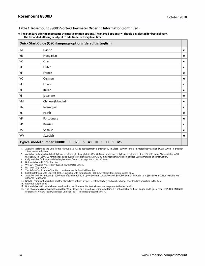
Quick Start Guide (QSG) language options (default is English)
YA Danish ★
YB Hungarian ★
YC Czech ★
YD Dutch ★
YF French ★
YG German ★
YH Finnish ★
YI Italian ★
YJ Japanese ★
YM Chinese (Mandarin) ★
YN Norwegian ★
YL Polish ★
YP Portuguese ★
YR Russian ★
YS Spanish ★
YW Swedish ★
Typical model number: 8800D F 020 S A1 N 1 D 1 M5
1. Available in Flanged and Dual from 6- through 12-in. and Reducer from 8- through 12-in. Class 1500 in 6- and 8-in. meter body sizes and Class 900 in 10- through 12-in. meterbody sizes.
2. Available on flanged and dual style meters from 1/2- through 8-in. (15–200 mm) and reducer style meters from 1– 8-in. (25–200 mm). Also available in 10- through12-in. (250-300 mm) flanged and dual meters along with 12-in. (300 mm) reducers when using Super Duplex material of construction.
3. Only available for flange and dual style meters from 1- through 8-in. (25–200 mm). 4. Not available with 1/2-in. line size.5. W1, W4, W8, and W9 are only available with Meter Style F.6. No Japan (E4) approval.7. The Safety Certifications SI option code is not available with this option8. Fieldbus Intrinsic Safe Concept (FISCO) available with output code F (FOUNDATION Fieldbus digital signal) only.9. Available with Rosemount 8800DF from 11/2- through 12-in. (40–300 mm). Available with 8800DR from 2- through 12-in.(50–300 mm). Not available with
8800DW or 8800DD.10. NAMUR compliant operation and the alarm latch options are pre-set at the factory and can be changed to standard operation in the field.11. Requires output code F.12. Not available with certain hazardous location certifications. Contact a Rosemount representative for details.13. The CPA option is not available on wafer, 1/2-in. flange, or 1-in. reducer units. In addition it is not available on 1-in. flanged and 11/2-in. reducer JIS 10K, EN PN40,
or EN PN16. Not available with Super Duplex or B31.1 line sizes greater than 6-in.
Table 1. Rosemount 8800D Vortex Flowmeter Ordering Information(continued)
★ The Standard offering represents the most common options. The starred options (★) should be selected for best delivery.__The Expanded offering is subject to additional delivery lead time.
14 www.emerson.com/rosemount
Rosemount 8800DOctober 2018
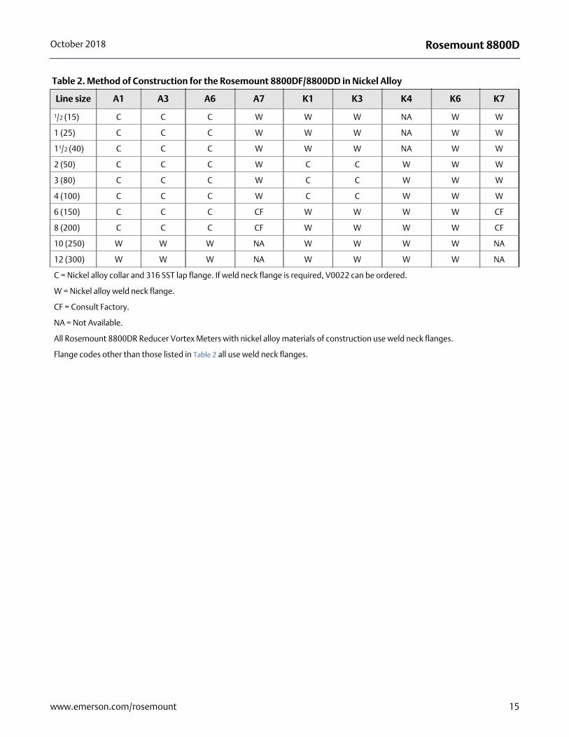
Table 2. Method of Construction for the Rosemount 8800DF/8800DD in Nickel Alloy
Line size A1 A3 A6 A7 K1 K3 K4 K6 K7
1/2 (15) C C C W W W NA W W
1 (25) C C C W W W NA W W
11/2 (40) C C C W W W NA W W
2 (50) C C C W C C W W W
3 (80) C C C W C C W W W
4 (100) C C C W C C W W W
6 (150) C C C CF W W W W CF
8 (200) C C C CF W W W W CF
10 (250) W W W NA W W W W NA
12 (300) W W W NA W W W W NA
C = Nickel alloy collar and 316 SST lap flange. If weld neck flange is required, V0022 can be ordered.
W = Nickel alloy weld neck flange.
CF = Consult Factory.
NA = Not Available.
All Rosemount 8800DR Reducer Vortex Meters with nickel alloy materials of construction use weld neck flanges.
Flange codes other than those listed in Table 2 all use weld neck flanges.
15www.emerson.com/rosemount
Rosemount 8800D October 2018
Specifications
Functional specifications
Process fluidsLiquid, gas, and steam applications. Fluids must be homogeneous and single-phase.
Line sizes
Wafer1/2, 1, 11/2, 2, 3, 4, 6, and 8 inches(DN 15, 25, 40, 50, 80, 100, 150, and 200)
Flanged and dual-sensor style1/2, 1, 11/2, 2, 3, 4, 6, 8, 10, and 12 inches(DN 15, 25, 40, 50, 80, 100, 150, 200, 250, and 300)
Reducer
1, 11/2, 2, 3, 4, 6, 8, 10, and 12 inches(DN 25, 40, 50, 80, 100, 150, 200, 250, and 300)
Pipe schedules
Process piping Schedules 10, 40, 80, and 160.
NoteThe appropriate bore diameter of the process piping must be entered using the Field Communicator or AMS Device Manager. Meters will be shipped from the factory at the Schedule 40 default value unless otherwise specified.
Measurable flow ratesCapable of processing signals from flow applications which meet the sizing requirements below. To determine the appropriate flowmeter size for an application, process conditions must be within the Reynolds number and velocity limitations for the desired line size provided in Table 3, Table 4, and Table 5.
NoteConsult your local sales representative to obtain a computer sizing program that describes in greater detail how to specify the correct flowmeter size for an application.
The Reynolds number equation shown below combines the effects of density (r), viscosity (mcp), pipe inside diameter (D), and flow velocity (V).
RDVDcp------------=
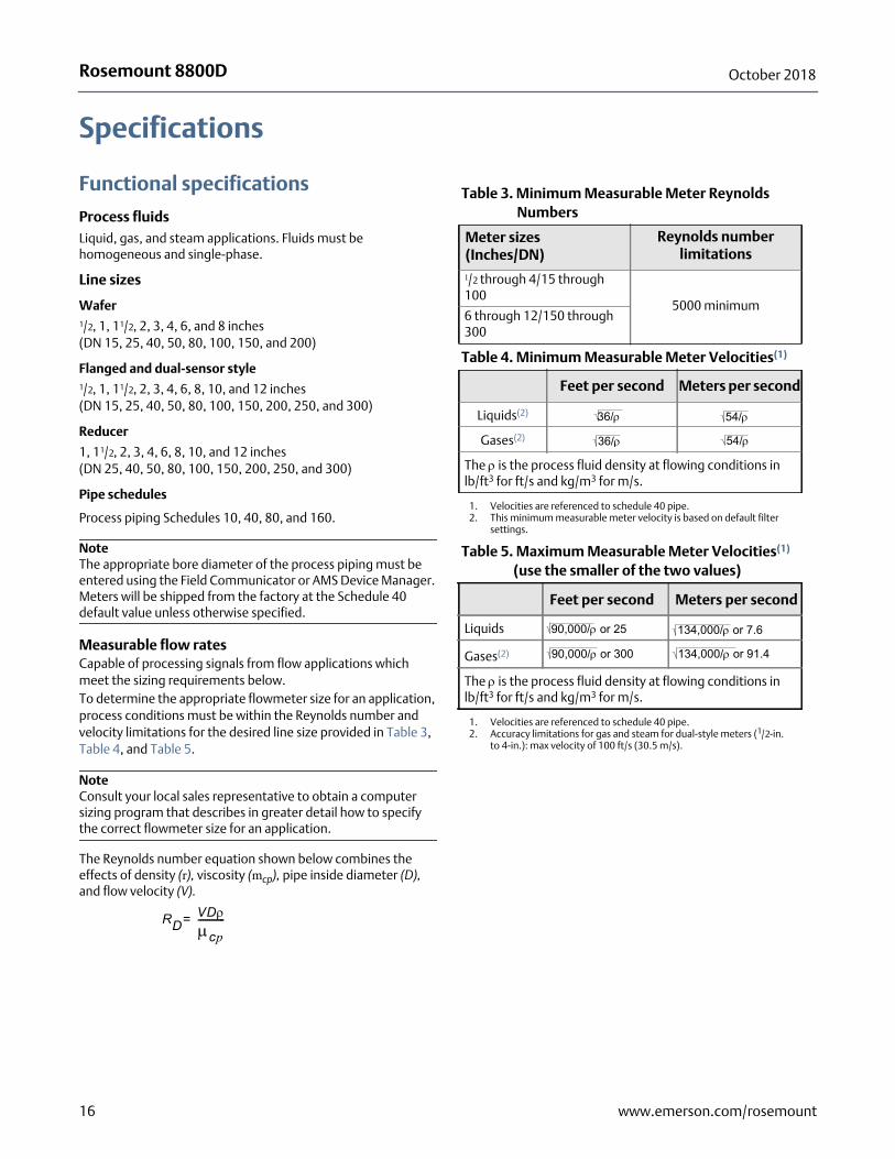
Table 3. Minimum Measurable Meter Reynolds Numbers
Meter sizes(Inches/DN)
Reynolds number limitations
1/2 through 4/15 through 100
5000 minimum6 through 12/150 through 300
Table 4. Minimum Measurable Meter Velocities(1)
1. Velocities are referenced to schedule 40 pipe.
Feet per second Meters per second
Liquids(2)
2. This minimum measurable meter velocity is based on default filter settings.
Gases(2)
The is the process fluid density at flowing conditions in lb/ft3 for ft/s and kg/m3 for m/s.
Table 5. Maximum Measurable Meter Velocities(1)
(use the smaller of the two values)
1. Velocities are referenced to schedule 40 pipe.
Feet per second Meters per second
Liquids
Gases(2)
2. Accuracy limitations for gas and steam for dual-style meters (1/2-in. to 4-in.): max velocity of 100 ft/s (30.5 m/s).
The is the process fluid density at flowing conditions in lb/ft3 for ft/s and kg/m3 for m/s.
36/ 54/
36/ 54/
90,000/ or 25 134,000/ or 7.6
90,000/ or 300 134,000/ or 91.4
16 www.emerson.com/rosemount
Rosemount 8800DOctober 2018
Process temperature limits
Standard
–40 to 450 °F (–40 to 232 °C)
Extended
–330 to 800 °F (–200 to 427 °C)
Severe–330 to 800 °F (–200 to 427 °C)
• The meter body and sensor, in remote mount configurations, is functionally rated to 842 °F process temperature. Process temperature may be further restricted depending on hazardous area options and PED certificates. Consult applicable certificates for particular installation limits.
• –320 °F to 800 °F (–196 to 427 °C) for European Pressure Equipment Directive (PED), consult factory for lower temperature requirements.
• The Super Duplex material of construction is limited to use in applications with process temperatures from –40 to 450 °F (–40 to 232 °C).
Multivariable (MTA option)
–40 to 800 °F (–40 to 427 °C)• Use above 450 °F (232 °C) requires Extended Sensor
Output signals
4–20 mA Digital HART signal
Superimposed on 4–20 mA signal
Optional scalable pulse output
0 to 10000 Hz; transistor switch closure with adjustable scaling via HART communications; capable of switching up to 30 Vdc, 120 mA maximum
Digital FOUNDATION Fieldbus signal
Completely digital output with FOUNDATION Fieldbus communication (ITK 6.0 compliant).
Analog output adjustmentEngineering units and lower and upper range values are user-selected. Output is automatically scaled to provide 4 mA at the selected lower range value, 20 mA at the selected upper range value. No frequency input is required to adjust the range values.
Scalable frequency adjustmentThe scalable pulse output can be set to a specific velocity, volume, or mass (i.e. 1 pulse = 1 lb). The scalable pulse output can also be scaled to a specific rate of volume, mass, or velocity (i.e. 100 Hz = 500 lb/hr).
Ambient temperature limits
Operating
–58 to 185 °F (–50 to 85 °C)–4 to 185 °F (–20 to 85 °C) for flowmeters with local indicator
Storage
–58 to 185 °F (–50 to 85 °C)–50 to 185 °F (–46 to 85 °C) for flowmeters with local indicator
Pressure limits
Flange style meter
Rated for ASME B16.5 Class 150, 300, 600, 900, and 1500, EN 1092-1 PN 10, 16, 25, 40, 63, 100, and 160, and JIS 10K, 20K, and 40K
Reducer style meter
Rated for ASME B16.5 Class 150, 300, 600, and 900, EN 1092-1 PN 10, 16, 25, 40, 63, 100, and 160.
Dual sensor style meter
Rated for ASME B16.5 Class 150, 300, 600, 900, and 1500, EN 1092-1 PN 10, 16, 25, 40, 63, 100, and 160, and JIS 10K, 20K, and 40K
Wafer style meter
Rated for ASME B16.5 Class 150, 300, and 600, EN 1092-1 PN 10, 16, 25, 40, 63, and 100, and JIS 10K, 20K, and 40K
NoteAll wafer style meters are pressure rated and labeled at 1500 PSI/10.34 MPa at 100 °F/38 °C regardless of alignment ring size code ordered.
Weld-end style meter
W1 Welds to Schedule 10 mating pipe • 1-4 inch line size 720 psig (4.96 MPa-g)
W4 Welds to Schedule 40 mating pipe • 1-4 inch line size 1440 psig (9.93 Mpa-g)
• 6-12 inch line size 720 psig (4.96 MPa-g)W8 Welds to Schedule 80 mating pipe
• 1-4 inch line size 2160 psig (14.9 Mpa-g)
• 6-12 inch line size 1440 psig (9.93 Mpa-g)W9 Welds to Schedule 160 mating pipe
• 1-4 inch line size 3600 psig (24.8 Mpa-g)
• 6-12 inch line size 2160 psig (14.9 Mpa-g)
Note1-in. (25 mm), and 1.5-in. (40 mm) weld to Schedule 80 mating pipe.
Power supply
HART analog
External power supply required. Flowmeter operates on 10.8 to 42 Vdc terminal voltage (with 250-ohm minimum load required for HART communications, 16.8 Vdc power supply is required)
FOUNDATION Fieldbus
External power supply required. Flowmeter operates on 9 to 32 Vdc, 18 mA maximum.
Power consumptionOne watt maximum
17www.emerson.com/rosemount
Rosemount 8800D October 2018
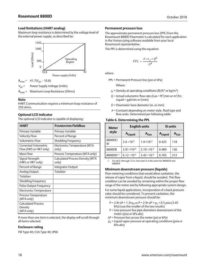
Load limitations (HART analog)Maximum loop resistance is determined by the voltage level of the external power supply, as described by:
NoteHART Communication requires a minimum loop resistance of 250 ohms.
Optional LCD indicatorThe optional LCD indicator is capable of displaying:
If more than one item is selected, the display will scroll through all items selected.
Enclosure ratingFM Type 4X; CSA Type 4X; IP66
Permanent pressure lossThe approximate permanent pressure loss (PPL) from the Rosemount 8800D Flowmeter is calculated for each application in the Vortex sizing software available from your local Rosemount representative.
The PPL is determined using the equation:
where:
Minimum downstream pressure (liquids)Flow metering conditions that would allow cavitation, the release of vapor from a liquid, should be avoided. This flow condition can be avoided by remaining within the proper flow range of the meter and by following appropriate system design.
For some liquid applications, incorporation of a back pressure valve should be considered. To prevent cavitation, the minimum downstream pressure should be:
Rmax = 41.7(Vps – 10.8)
Vps = Power Supply Voltage (Volts)
Rmax = Maximum Loop Resistance (Ohms)
HART FOUNDATION Fieldbus
Primary Variable Primary Variable
Velocity Flow Percent of Range
Volumetric Flow Shedding Frequency
Corrected Volumetric Flow (HR5 or HR7 only)
Electronics Temperature (MTA only)
Mass Flow Process Temperature (MTA only)
Signal Strength(HR5 or HR7 only)
Calculated Process Density (MTA only)
Percent of Range Integrator Output
Analog Output Totalizer
Totalizer
Shedding Frequency
Pulse Output Frequency
Electronics Temperature
Process Temperature (MTA only)
Calculated Process Density (MTA only)
Power supply (Volts)
Load
(Ohm
s)
OperatingRegion
1250
1000
500
0
10.8 42
PPL = Permanent Pressure loss (psi or kPa)
Where:
ρf = Density at operating conditions (lb/ft3 or kg/m3)
Q = Actual volumetric flow rate (Gas = ft3/min or m3/hr; Liquid = gal/min or l/min)
D = Flowmeter bore diameter (in. or mm)
A = Constant depending on meter style, fluid type and flow units. Determined per following table:
Table 6. Determining the PPL
Meter style
English units SI units
ALiquid AGas ALiquid AGas
8800DF/W
3.4 ×10⁻⁵ 1.9 ×10⁻³ 0.425 118
8800DR 3.91 ×10⁻⁵ 2.19 ×10⁻³ 0.489 136
8800DD(1)
1. For all 6- through 12-in. line sizes A is the same for 8800DD and 8800DF
6.12 ×10⁻⁵ 3.42 ×10⁻³ 0.765 212
P = 2.9P + 1.3pv or P = 2.9P + pv + 0.5 psia (3.45 kPa) (use the smaller of the two results)
P = Line pressure five pipe diameters downstream of the meter (psia or kPa abs)
P = Pressure loss across the meter (psi or kPa)pv = Liquid vapor pressure at operating conditions (psia or
kPa abs)
PPLA f Q2
D4--------------------------------=
18 www.emerson.com/rosemount
Rosemount 8800DOctober 2018
Failure mode alarm
HART analog
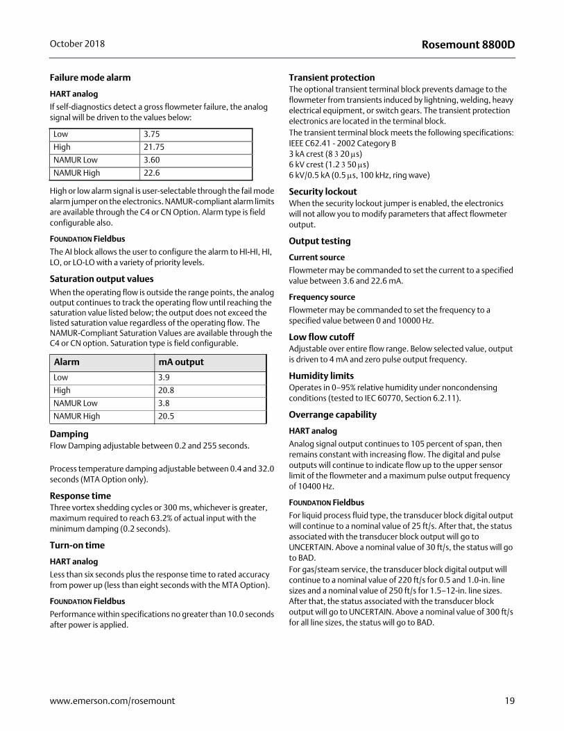
If self-diagnostics detect a gross flowmeter failure, the analog signal will be driven to the values below:
High or low alarm signal is user-selectable through the fail mode alarm jumper on the electronics. NAMUR-compliant alarm limits are available through the C4 or CN Option. Alarm type is field configurable also.
FOUNDATION Fieldbus
The AI block allows the user to configure the alarm to HI-HI, HI, LO, or LO-LO with a variety of priority levels.
Saturation output valuesWhen the operating flow is outside the range points, the analog output continues to track the operating flow until reaching the saturation value listed below; the output does not exceed the listed saturation value regardless of the operating flow. The NAMUR-Compliant Saturation Values are available through the C4 or CN option. Saturation type is field configurable.
DampingFlow Damping adjustable between 0.2 and 255 seconds.
Process temperature damping adjustable between 0.4 and 32.0 seconds (MTA Option only).
Response timeThree vortex shedding cycles or 300 ms, whichever is greater, maximum required to reach 63.2% of actual input with the minimum damping (0.2 seconds).
Turn-on time
HART analog
Less than six seconds plus the response time to rated accuracy from power up (less than eight seconds with the MTA Option).
FOUNDATION Fieldbus
Performance within specifications no greater than 10.0 seconds after power is applied.
Transient protectionThe optional transient terminal block prevents damage to the flowmeter from transients induced by lightning, welding, heavy electrical equipment, or switch gears. The transient protection electronics are located in the terminal block.The transient terminal block meets the following specifications:IEEE C62.41 - 2002 Category B 3 kA crest (8 3 20 s)6 kV crest (1.2 3 50 s)6 kV/0.5 kA (0.5 s, 100 kHz, ring wave)
Security lockoutWhen the security lockout jumper is enabled, the electronics will not allow you to modify parameters that affect flowmeter output.
Output testing
Current source
Flowmeter may be commanded to set the current to a specified value between 3.6 and 22.6 mA.
Frequency source
Flowmeter may be commanded to set the frequency to a specified value between 0 and 10000 Hz.
Low flow cutoffAdjustable over entire flow range. Below selected value, output is driven to 4 mA and zero pulse output frequency.
Humidity limitsOperates in 0–95% relative humidity under noncondensing conditions (tested to IEC 60770, Section 6.2.11).
Overrange capability
HART analog
Analog signal output continues to 105 percent of span, then remains constant with increasing flow. The digital and pulse outputs will continue to indicate flow up to the upper sensor limit of the flowmeter and a maximum pulse output frequency of 10400 Hz.
FOUNDATION Fieldbus
For liquid process fluid type, the transducer block digital output will continue to a nominal value of 25 ft/s. After that, the status associated with the transducer block output will go to UNCERTAIN. Above a nominal value of 30 ft/s, the status will go to BAD. For gas/steam service, the transducer block digital output will continue to a nominal value of 220 ft/s for 0.5 and 1.0-in. line sizes and a nominal value of 250 ft/s for 1.5–12-in. line sizes. After that, the status associated with the transducer block output will go to UNCERTAIN. Above a nominal value of 300 ft/s for all line sizes, the status will go to BAD.
Low 3.75
High 21.75
NAMUR Low 3.60
NAMUR High 22.6
Alarm mA output
Low 3.9
High 20.8
NAMUR Low 3.8
NAMUR High 20.5
19www.emerson.com/rosemount
Rosemount 8800D October 2018
Flow calibrationMeter bodies are flow-calibrated and assigned a unique calibration factor (K-factor) at the factory. The calibration factor is entered into the electronics, enabling interchangeability of electronics and/or sensors without calculations or compromise in accuracy of the calibrated meter body.
Status (FOUNDATION Fieldbus only)If self-diagnostics detect a transmitter failure, the status of the measurement will inform the control system. Status may also set the PID output to a safe value.
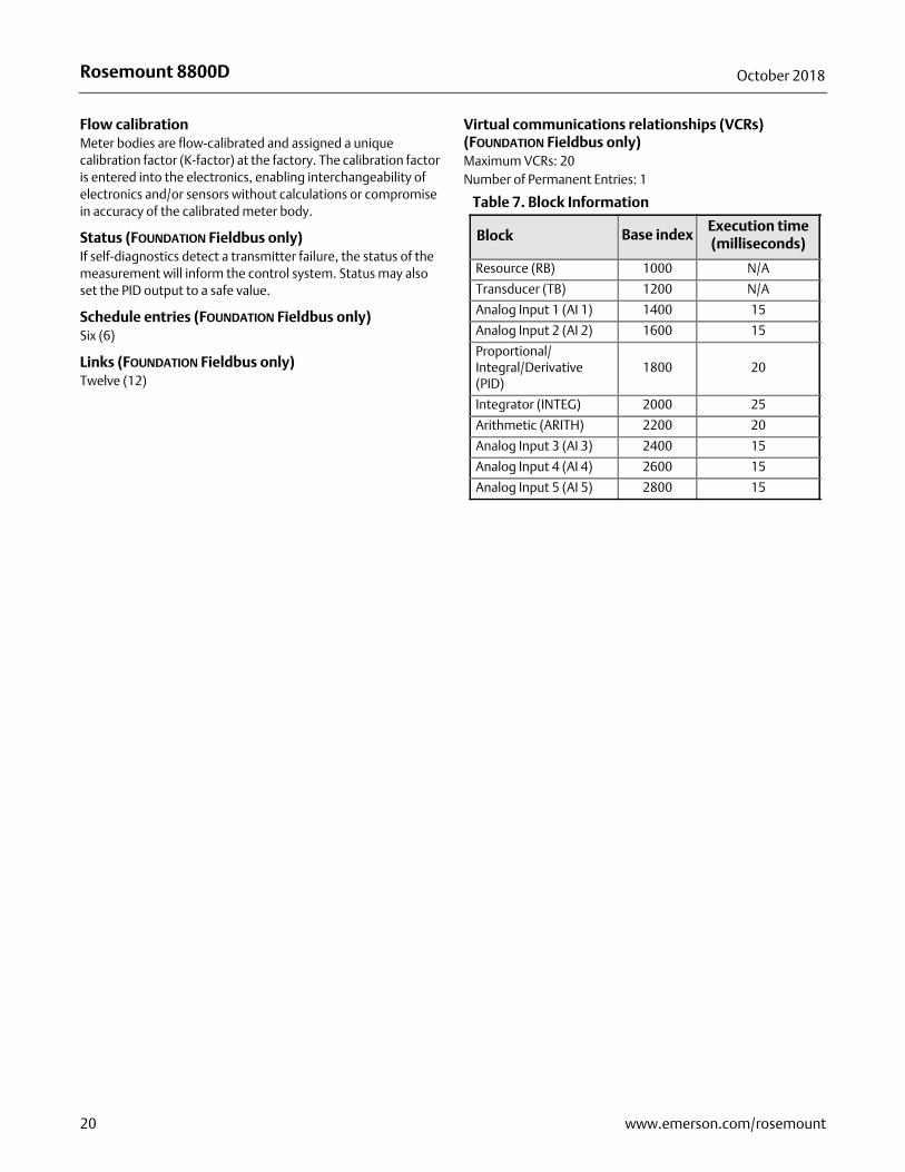
Schedule entries (FOUNDATION Fieldbus only)Six (6)
Links (FOUNDATION Fieldbus only)Twelve (12)
Virtual communications relationships (VCRs) (FOUNDATION Fieldbus only)Maximum VCRs: 20Number of Permanent Entries: 1
Table 7. Block Information
Block Base indexExecution time (milliseconds)
Resource (RB) 1000 N/A
Transducer (TB) 1200 N/A
Analog Input 1 (AI 1) 1400 15
Analog Input 2 (AI 2) 1600 15
Proportional/Integral/Derivative (PID)
1800 20
Integrator (INTEG) 2000 25
Arithmetic (ARITH) 2200 20
Analog Input 3 (AI 3) 2400 15
Analog Input 4 (AI 4) 2600 15
Analog Input 5 (AI 5) 2800 15
20 www.emerson.com/rosemount
Rosemount 8800DOctober 2018
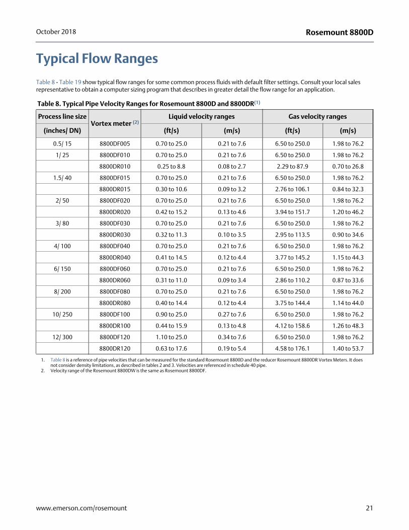
Typical Flow Ranges
Table 8 - Table 19 show typical flow ranges for some common process fluids with default filter settings. Consult your local sales representative to obtain a computer sizing program that describes in greater detail the flow range for an application.
Table 8. Typical Pipe Velocity Ranges for Rosemount 8800D and 8800DR(1)
1. Table 8 is a reference of pipe velocities that can be measured for the standard Rosemount 8800D and the reducer Rosemount 8800DR Vortex Meters. It does not consider density limitations, as described in tables 2 and 3. Velocities are referenced in schedule 40 pipe.
Process line sizeVortex meter (2)
2. Velocity range of the Rosemount 8800DW is the same as Rosemount 8800DF.
Liquid velocity ranges Gas velocity ranges
(inches/ DN) (ft/s) (m/s) (ft/s) (m/s)
0.5/ 15 8800DF005 0.70 to 25.0 0.21 to 7.6 6.50 to 250.0 1.98 to 76.2
1/ 25 8800DF010 0.70 to 25.0 0.21 to 7.6 6.50 to 250.0 1.98 to 76.2
8800DR010 0.25 to 8.8 0.08 to 2.7 2.29 to 87.9 0.70 to 26.8
1.5/ 40 8800DF015 0.70 to 25.0 0.21 to 7.6 6.50 to 250.0 1.98 to 76.2
8800DR015 0.30 to 10.6 0.09 to 3.2 2.76 to 106.1 0.84 to 32.3
2/ 50 8800DF020 0.70 to 25.0 0.21 to 7.6 6.50 to 250.0 1.98 to 76.2
8800DR020 0.42 to 15.2 0.13 to 4.6 3.94 to 151.7 1.20 to 46.2
3/ 80 8800DF030 0.70 to 25.0 0.21 to 7.6 6.50 to 250.0 1.98 to 76.2
8800DR030 0.32 to 11.3 0.10 to 3.5 2.95 to 113.5 0.90 to 34.6
4/ 100 8800DF040 0.70 to 25.0 0.21 to 7.6 6.50 to 250.0 1.98 to 76.2
8800DR040 0.41 to 14.5 0.12 to 4.4 3.77 to 145.2 1.15 to 44.3
6/ 150 8800DF060 0.70 to 25.0 0.21 to 7.6 6.50 to 250.0 1.98 to 76.2
8800DR060 0.31 to 11.0 0.09 to 3.4 2.86 to 110.2 0.87 to 33.6
8/ 200 8800DF080 0.70 to 25.0 0.21 to 7.6 6.50 to 250.0 1.98 to 76.2
8800DR080 0.40 to 14.4 0.12 to 4.4 3.75 to 144.4 1.14 to 44.0
10/ 250 8800DF100 0.90 to 25.0 0.27 to 7.6 6.50 to 250.0 1.98 to 76.2
8800DR100 0.44 to 15.9 0.13 to 4.8 4.12 to 158.6 1.26 to 48.3
12/ 300 8800DF120 1.10 to 25.0 0.34 to 7.6 6.50 to 250.0 1.98 to 76.2
8800DR120 0.63 to 17.6 0.19 to 5.4 4.58 to 176.1 1.40 to 53.7
21www.emerson.com/rosemount
Rosemount 8800D October 2018
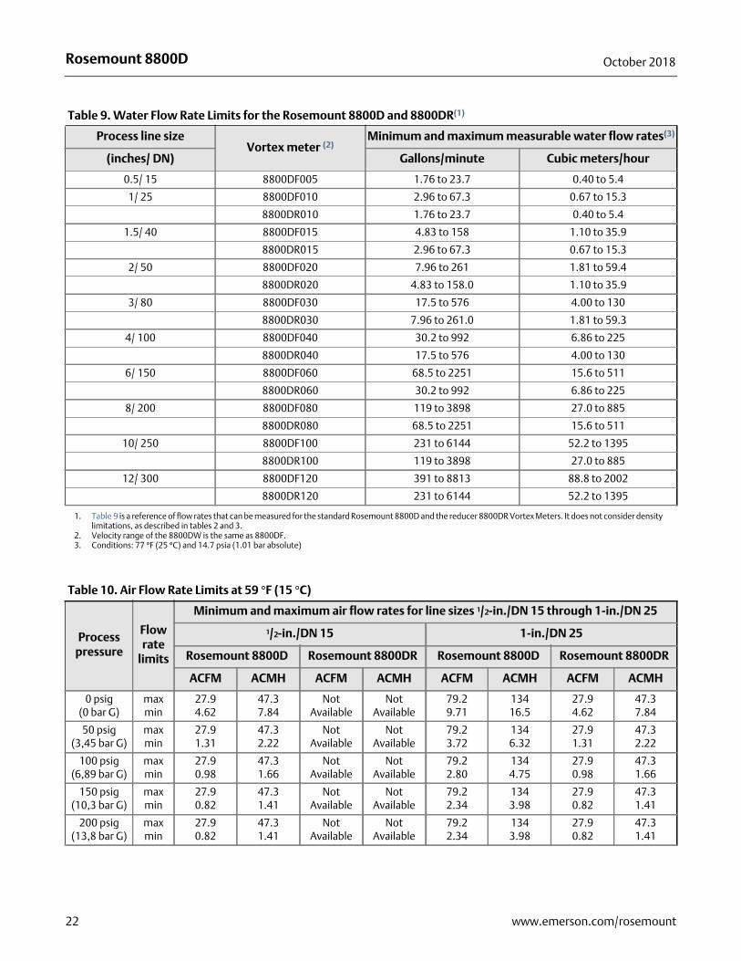
Table 9. Water Flow Rate Limits for the Rosemount 8800D and 8800DR(1)
1. Table 9 is a reference of flow rates that can be measured for the standard Rosemount 8800D and the reducer 8800DR Vortex Meters. It does not consider density limitations, as described in tables 2 and 3.
Process line sizeVortex meter (2)
2. Velocity range of the 8800DW is the same as 8800DF.
Minimum and maximum measurable water flow rates(3)
3. Conditions: 77 °F (25 °C) and 14.7 psia (1.01 bar absolute)
(inches/ DN) Gallons/minute Cubic meters/hour
0.5/ 15 8800DF005 1.76 to 23.7 0.40 to 5.4
1/ 25 8800DF010 2.96 to 67.3 0.67 to 15.3
8800DR010 1.76 to 23.7 0.40 to 5.4
1.5/ 40 8800DF015 4.83 to 158 1.10 to 35.9
8800DR015 2.96 to 67.3 0.67 to 15.3
2/ 50 8800DF020 7.96 to 261 1.81 to 59.4
8800DR020 4.83 to 158.0 1.10 to 35.9
3/ 80 8800DF030 17.5 to 576 4.00 to 130
8800DR030 7.96 to 261.0 1.81 to 59.3
4/ 100 8800DF040 30.2 to 992 6.86 to 225
8800DR040 17.5 to 576 4.00 to 130
6/ 150 8800DF060 68.5 to 2251 15.6 to 511
8800DR060 30.2 to 992 6.86 to 225
8/ 200 8800DF080 119 to 3898 27.0 to 885
8800DR080 68.5 to 2251 15.6 to 511
10/ 250 8800DF100 231 to 6144 52.2 to 1395
8800DR100 119 to 3898 27.0 to 885
12/ 300 8800DF120 391 to 8813 88.8 to 2002
8800DR120 231 to 6144 52.2 to 1395
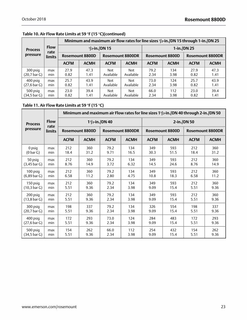
Table 10. Air Flow Rate Limits at 59 °F (15 °C)
Process pressure
Flow rate
limits
Minimum and maximum air flow rates for line sizes 1/2-in./DN 15 through 1-in./DN 25
1/2-in./DN 15 1-in./DN 25
Rosemount 8800D Rosemount 8800DR Rosemount 8800D Rosemount 8800DR
ACFM ACMH ACFM ACMH ACFM ACMH ACFM ACMH
0 psig(0 bar G)
maxmin
27.94.62
47.37.84
Not Available
Not Available
79.29.71
13416.5
27.94.62
47.37.84
50 psig(3,45 bar G)
maxmin
27.91.31
47.32.22
Not Available
Not Available
79.23.72
1346.32
27.91.31
47.32.22
100 psig(6,89 bar G)
maxmin
27.90.98
47.31.66
Not Available
Not Available
79.22.80
1344.75
27.90.98
47.31.66
150 psig(10,3 bar G)
maxmin
27.90.82
47.31.41
Not Available
Not Available
79.22.34
1343.98
27.90.82
47.31.41
200 psig(13,8 bar G)
maxmin
27.90.82
47.31.41
Not Available
Not Available
79.22.34
1343.98
27.90.82
47.31.41
22 www.emerson.com/rosemount
Rosemount 8800DOctober 2018
300 psig(20,7 bar G)
maxmin
27.90.82
47.31.41
Not Available
Not Available
79.22.34
1343.98
27.90.82
47.31.41
400 psig(27,6 bar G)
maxmin
25.70.82
43.91.41
Not Available
Not Available
73.02.34
1243.98
25.70.82
43.91.41
500 psig(34,5 bar G)
maxmin
23.00.82
39.41.41
Not Available
Not Available
66.02.34
1123.98
23.00.82
39.41.41
Table 11. Air Flow Rate Limits at 59 °F (15 °C)
Process pressure
Flow rate
limits
Minimum and maximum air Flow rates for line sizes 11/2-in./DN 40 through 2-in./DN 50
11/2-in./DN 40 2-in./DN 50
Rosemount 8800D Rosemount 8800DR Rosemount 8800D Rosemount 8800DR
ACFM ACMH ACFM ACMH ACFM ACMH ACFM ACMH
0 psig(0 bar G)
maxmin
21218.4
36031.2
79.29.71
13416.5
34930.3
59351.5
21218.4
36031.2
50 psig(3,45 bar G)
maxmin
2128.76
36014.9
79.23.72
1346.32
34914.5
59324.6
2128.76
36014.9
100 psig(6,89 bar G)
maxmin
2126.58
36011.2
79.22.80
1344.75
34910.8
59318.3
2126.58
36011.2
150 psig(10,3 bar G)
maxmin
2125.51
3609.36
79.22.34
1343.98
3499.09
59315.4
2125.51
3609.36
200 psig(13,8 bar G)
maxmin
2125.51
3609.36
79.22.34
1343.98
3499.09
59315.4
2125.51
3609.36
300 psig(20,7 bar G)
maxmin
1985.51
3379.36
79.22.34
1343.98
3269.09
55415.4
1985.51
3379.36
400 psig(27,6 bar G)
maxmin
1725.51
2939.36
73.02.34
1243.98
2849.09
48315.4
1725.51
2939.36
500 psig(34,5 bar G)
maxmin
1545.51
2629.36
66.02.34
1123.98
2549.09
43215.4
1545.51
2629.36
Table 10. Air Flow Rate Limits at 59 °F (15 °C)(continued)
Process pressure
Flow rate
limits
Minimum and maximum air flow rates for line sizes 1/2-in./DN 15 through 1-in./DN 25
1/2-in./DN 15 1-in./DN 25
Rosemount 8800D Rosemount 8800DR Rosemount 8800D Rosemount 8800DR
ACFM ACMH ACFM ACMH ACFM ACMH ACFM ACMH
23www.emerson.com/rosemount
Rosemount 8800D October 2018
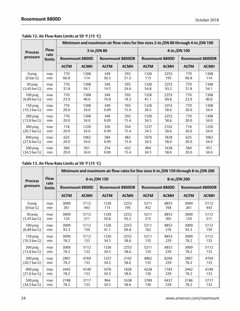
Table 12. Air Flow Rate Limits at 59 °F (15 °C)
Process pressure
Flow rate
limits
Minimum and maximum air flow rates for line sizes 3-in./DN 80 through 4-in./DN 100
3-in./DN 80 4-in./DN 100
Rosemount 8800D Rosemount 8800DR Rosemount 8800D Rosemount 8800DR
ACFM ACMH ACFM ACMH ACFM ACMH ACFM ACMH
0 psig(0 bar G)
maxmin
77066.8
1308114
34930.3
59351.5
1326115
2253195
77066.8
1308114
50 psig(3,45 bar G)
maxmin
77031.8
130854.1
34914.5
59324.6
132654.8
225393.2
77031.8
130854.1
100 psig(6,89 bar G)
maxmin
77023.9
130840.6
34910.8
59318.3
132641.1
225369.8
77023.9
130840.6
150 psig(10,3 bar G)
maxmin
77020.0
130834.0
3499.09
59315.4
132634.5
225358.6
77020.0
130834.0
200 psig(13,8 bar G)
maxmin
77020.0
130834.0
3499.09
59315.4
132634.5
225358.6
77020.0
130834.0
300 psig(20,7 bar G)
maxmin
71820.0
122034.0
3269.09
55415.4
123734.5
210258.6
71820.0
122034.0
400 psig(27,6 bar G)
maxmin
62520.0
106234.0
2849.09
48315.4
107634.5
182858.6
62520.0
106234.0
500 psig(34,5 bar G)
maxmin
56020.0
95134.0
2549.09
43215.4
96434.5
163858.6
56020.0
95134.0
Table 13. Air Flow Rate Limits at 59 °F (15 °C)
Process pressure
Flow rate
limits
Minimum and maximum air flow rates for line sizes 6-in./DN 150 through 8-in./DN 200
6-in./DN 150 8-in./DN 200
Rosemount 8800D Rosemount 8800DR Rosemount 8800D Rosemount 8800DR
ACFM ACMH ACFM ACMH ACFM ACMH ACFM ACMH
0 psig(0 bar G)
maxmin
3009261
5112443
1326115
2253195
5211452
8853768
3009261
5112443
50 psig(3,45 bar G)
maxmin
3009124
5112211
132654.8
225393.2
5211215
8853365
3009124
5112211
100 psig(6,89 bar G)
maxmin
300993.3
5112159
132641.1
225369.8
5211162
8853276
300993.3
5112159
150 psig(10,3 bar G)
maxmin
300978.2
5112133
132634.5
225358.6
5211135
8853229
300978.2
5112133
200 psig(13,8 bar G)
maxmin
300978.2
5112133
132634.5
225358.6
5211135
8853229
300978.2
5112133
300 psig(20,7 bar G)
maxmin
280778.2
4769133
123734.5
210258.6
4862135
8260229
280778.2
4769133
400 psig(27,6 bar G)
maxmin
244278.2
4149133
107634.5
182858.6
4228136
7183229
244278.2
4149133
500 psig(34,5 bar G)
maxmin
218878.2
3717133
96434.5
163858.6
3789136
6437229
218878.2
3717133
24 www.emerson.com/rosemount
Rosemount 8800DOctober 2018
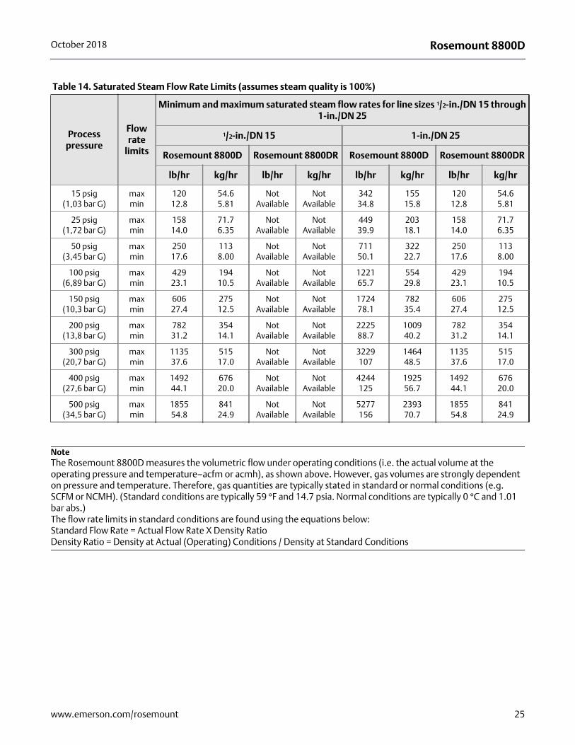
NoteThe Rosemount 8800D measures the volumetric flow under operating conditions (i.e. the actual volume at the operating pressure and temperature–acfm or acmh), as shown above. However, gas volumes are strongly dependent on pressure and temperature. Therefore, gas quantities are typically stated in standard or normal conditions (e.g. SCFM or NCMH). (Standard conditions are typically 59 °F and 14.7 psia. Normal conditions are typically 0 °C and 1.01 bar abs.) The flow rate limits in standard conditions are found using the equations below: Standard Flow Rate = Actual Flow Rate X Density Ratio Density Ratio = Density at Actual (Operating) Conditions / Density at Standard Conditions
Table 14. Saturated Steam Flow Rate Limits (assumes steam quality is 100%)
Process pressure
Flow rate
limits
Minimum and maximum saturated steam flow rates for line sizes 1/2-in./DN 15 through 1-in./DN 25
1/2-in./DN 15 1-in./DN 25
Rosemount 8800D Rosemount 8800DR Rosemount 8800D Rosemount 8800DR
lb/hr kg/hr lb/hr kg/hr lb/hr kg/hr lb/hr kg/hr
15 psig(1,03 bar G)
maxmin
12012.8
54.65.81
Not Available
Not Available
34234.8
15515.8
12012.8
54.65.81
25 psig(1,72 bar G)
maxmin
15814.0
71.76.35
Not Available
Not Available
44939.9
20318.1
15814.0
71.76.35
50 psig(3,45 bar G)
maxmin
25017.6
1138.00
Not Available
Not Available
71150.1
32222.7
25017.6
1138.00
100 psig(6,89 bar G)
maxmin
42923.1
19410.5
Not Available
Not Available
122165.7
55429.8
42923.1
19410.5
150 psig(10,3 bar G)
maxmin
60627.4
27512.5
Not Available
Not Available
172478.1
78235.4
60627.4
27512.5
200 psig(13,8 bar G)
maxmin
78231.2
35414.1
Not Available
Not Available
222588.7
100940.2
78231.2
35414.1
300 psig(20,7 bar G)
maxmin
113537.6
51517.0
Not Available
Not Available
3229107
146448.5
113537.6
51517.0
400 psig(27,6 bar G)
maxmin
149244.1
67620.0
Not Available
Not Available
4244125
192556.7
149244.1
67620.0
500 psig(34,5 bar G)
maxmin
185554.8
84124.9
Not Available
Not Available
5277156
239370.7
185554.8
84124.9
25www.emerson.com/rosemount
Rosemount 8800D October 2018
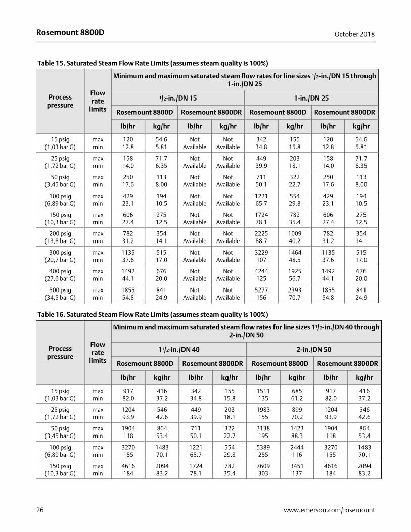
Table 15. Saturated Steam Flow Rate Limits (assumes steam quality is 100%)
Process pressure
Flow rate
limits
Minimum and maximum saturated steam flow rates for line sizes 1/2-in./DN 15 through 1-in./DN 25
1/2-in./DN 15 1-in./DN 25
Rosemount 8800D Rosemount 8800DR Rosemount 8800D Rosemount 8800DR
lb/hr kg/hr lb/hr kg/hr lb/hr kg/hr lb/hr kg/hr
15 psig(1,03 bar G)
maxmin
12012.8
54.65.81
Not Available
Not Available
34234.8
15515.8
12012.8
54.65.81
25 psig(1,72 bar G)
maxmin
15814.0
71.76.35
Not Available
Not Available
44939.9
20318.1
15814.0
71.76.35
50 psig(3,45 bar G)
maxmin
25017.6
1138.00
Not Available
Not Available
71150.1
32222.7
25017.6
1138.00
100 psig(6,89 bar G)
maxmin
42923.1
19410.5
Not Available
Not Available
122165.7
55429.8
42923.1
19410.5
150 psig(10,3 bar G)
maxmin
60627.4
27512.5
Not Available
Not Available
172478.1
78235.4
60627.4
27512.5
200 psig(13,8 bar G)
maxmin
78231.2
35414.1
Not Available
Not Available
222588.7
100940.2
78231.2
35414.1
300 psig(20,7 bar G)
maxmin
113537.6
51517.0
Not Available
Not Available
3229107
146448.5
113537.6
51517.0
400 psig(27,6 bar G)
maxmin
149244.1
67620.0
Not Available
Not Available
4244125
192556.7
149244.1
67620.0
500 psig(34,5 bar G)
maxmin
185554.8
84124.9
Not Available
Not Available
5277156
239370.7
185554.8
84124.9
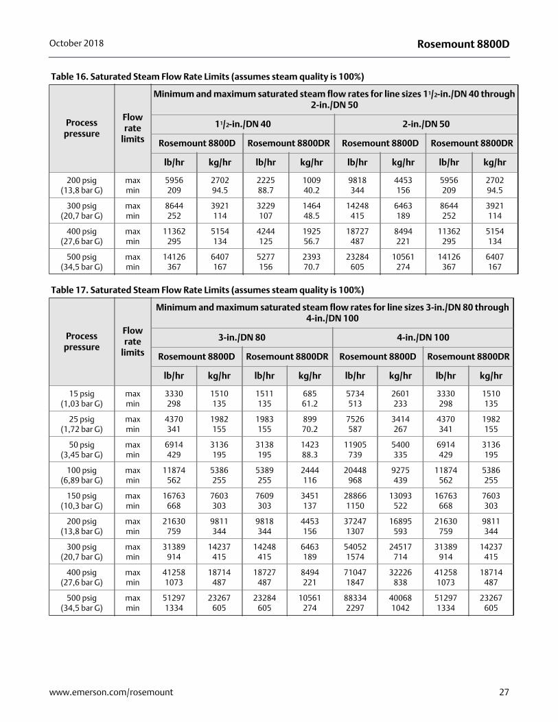
Table 16. Saturated Steam Flow Rate Limits (assumes steam quality is 100%)
Process pressure
Flow rate
limits
Minimum and maximum saturated steam flow rates for line sizes 11/2-in./DN 40 through 2-in./DN 50
11/2-in./DN 40 2-in./DN 50
Rosemount 8800D Rosemount 8800DR Rosemount 8800D Rosemount 8800DR
lb/hr kg/hr lb/hr kg/hr lb/hr kg/hr lb/hr kg/hr
15 psig(1,03 bar G)
maxmin
91782.0
41637.2
34234.8
15515.8
1511135
68561.2
91782.0
41637.2
25 psig(1,72 bar G)
maxmin
120493.9
54642.6
44939.9
20318.1
1983155
89970.2
120493.9
54642.6
50 psig(3,45 bar G)
maxmin
1904118
86453.4
71150.1
32222.7
3138195
142388.3
1904118
86453.4
100 psig(6,89 bar G)
maxmin
3270155
148370.1
122165.7
55429.8
5389255
2444116
3270155
148370.1
150 psig(10,3 bar G)
maxmin
4616184
209483.2
172478.1
78235.4
7609303
3451137
4616184
209483.2
26 www.emerson.com/rosemount
Rosemount 8800DOctober 2018
200 psig(13,8 bar G)
maxmin
5956209
270294.5
222588.7
100940.2
9818344
4453156
5956209
270294.5
300 psig(20,7 bar G)
maxmin
8644252
3921114
3229107
146448.5
14248415
6463189
8644252
3921114
400 psig(27,6 bar G)
maxmin
11362295
5154134
4244125
192556.7
18727487
8494221
11362295
5154134
500 psig(34,5 bar G)
maxmin
14126367
6407167
5277156
239370.7
23284605
10561274
14126367
6407167
Table 17. Saturated Steam Flow Rate Limits (assumes steam quality is 100%)
Process pressure
Flow rate
limits
Minimum and maximum saturated steam flow rates for line sizes 3-in./DN 80 through 4-in./DN 100
3-in./DN 80 4-in./DN 100
Rosemount 8800D Rosemount 8800DR Rosemount 8800D Rosemount 8800DR
lb/hr kg/hr lb/hr kg/hr lb/hr kg/hr lb/hr kg/hr
15 psig(1,03 bar G)
maxmin
3330298
1510135
1511135
68561.2
5734513
2601233
3330298
1510135
25 psig(1,72 bar G)
maxmin
4370341
1982155
1983155
89970.2
7526587
3414267
4370341
1982155
50 psig(3,45 bar G)
maxmin
6914429
3136195
3138195
142388.3
11905739
5400335
6914429
3136195
100 psig(6,89 bar G)
maxmin
11874562
5386255
5389255
2444116
20448968
9275439
11874562
5386255
150 psig(10,3 bar G)
maxmin
16763668
7603303
7609303
3451137
288661150
13093522
16763668
7603303
200 psig(13,8 bar G)
maxmin
21630759
9811344
9818344
4453156
372471307
16895593
21630759
9811344
300 psig(20,7 bar G)
maxmin
31389914
14237415
14248415
6463189
540521574
24517714
31389914
14237415
400 psig(27,6 bar G)
maxmin
412581073
18714487
18727487
8494221
710471847
32226838
412581073
18714487
500 psig(34,5 bar G)
maxmin
512971334
23267605
23284605
10561274
883342297
400681042
512971334
23267605
Table 16. Saturated Steam Flow Rate Limits (assumes steam quality is 100%)
Process pressure
Flow rate
limits
Minimum and maximum saturated steam flow rates for line sizes 11/2-in./DN 40 through 2-in./DN 50
11/2-in./DN 40 2-in./DN 50
Rosemount 8800D Rosemount 8800DR Rosemount 8800D Rosemount 8800DR
lb/hr kg/hr lb/hr kg/hr lb/hr kg/hr lb/hr kg/hr
27www.emerson.com/rosemount
Rosemount 8800D October 2018
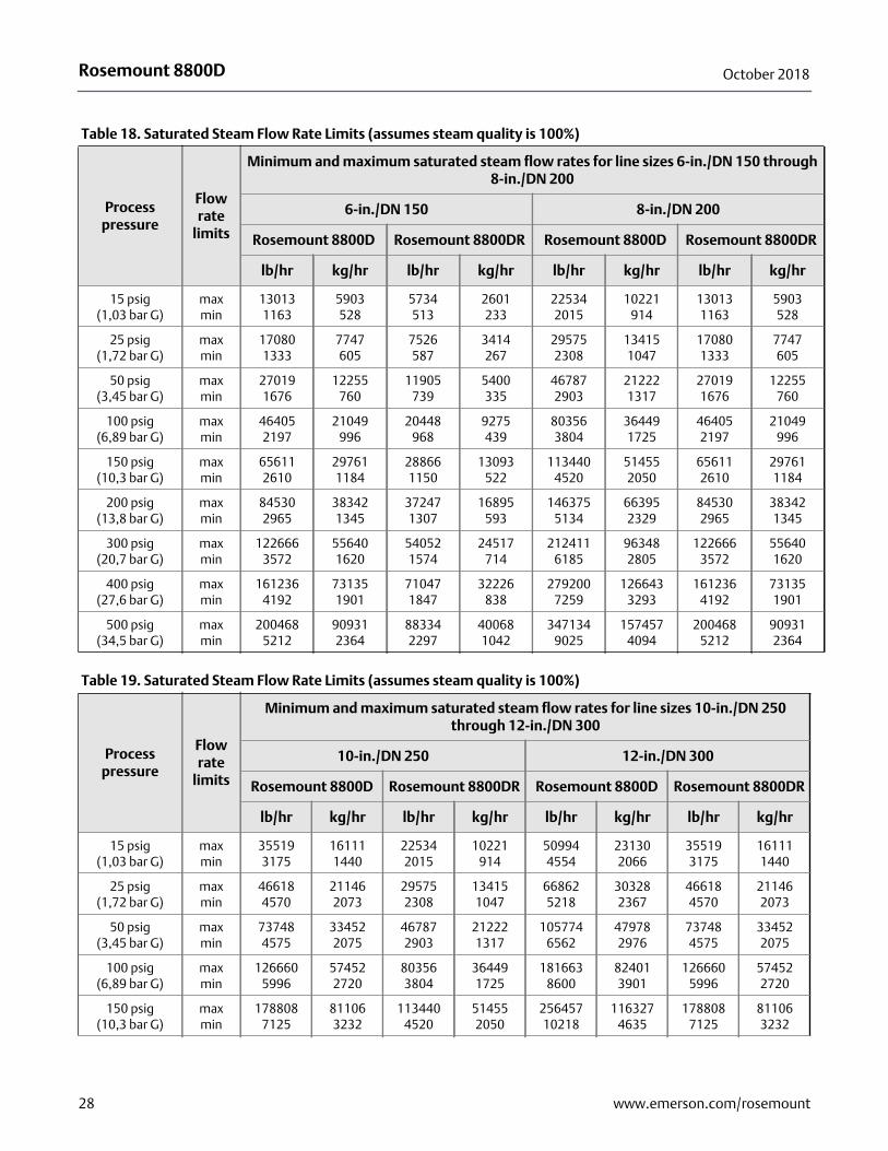
Table 18. Saturated Steam Flow Rate Limits (assumes steam quality is 100%)
Process pressure
Flow rate
limits
Minimum and maximum saturated steam flow rates for line sizes 6-in./DN 150 through 8-in./DN 200
6-in./DN 150 8-in./DN 200
Rosemount 8800D Rosemount 8800DR Rosemount 8800D Rosemount 8800DR
lb/hr kg/hr lb/hr kg/hr lb/hr kg/hr lb/hr kg/hr
15 psig(1,03 bar G)
maxmin
130131163
5903528
5734513
2601233
225342015
10221914
130131163
5903528
25 psig(1,72 bar G)
maxmin
170801333
7747605
7526587
3414267
295752308
134151047
170801333
7747605
50 psig(3,45 bar G)
maxmin
270191676
12255760
11905739
5400335
467872903
212221317
270191676
12255760
100 psig(6,89 bar G)
maxmin
464052197
21049996
20448968
9275439
803563804
364491725
464052197
21049996
150 psig(10,3 bar G)
maxmin
656112610
297611184
288661150
13093522
1134404520
514552050
656112610
297611184
200 psig(13,8 bar G)
maxmin
845302965
383421345
372471307
16895593
1463755134
663952329
845302965
383421345
300 psig(20,7 bar G)
maxmin
1226663572
556401620
540521574
24517714
2124116185
963482805
1226663572
556401620
400 psig(27,6 bar G)
maxmin
1612364192
731351901
710471847
32226838
2792007259
1266433293
1612364192
731351901
500 psig(34,5 bar G)
maxmin
2004685212
909312364
883342297
400681042
3471349025
1574574094
2004685212
909312364
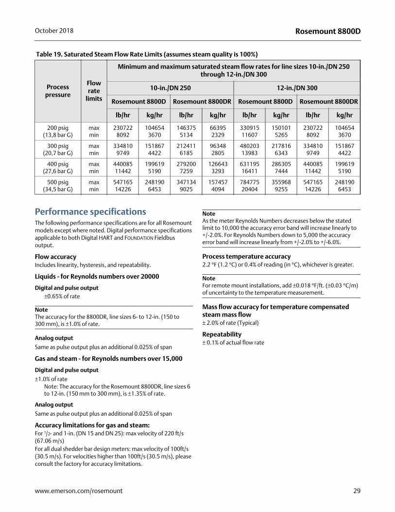
Table 19. Saturated Steam Flow Rate Limits (assumes steam quality is 100%)
Process pressure
Flow rate
limits
Minimum and maximum saturated steam flow rates for line sizes 10-in./DN 250 through 12-in./DN 300
10-in./DN 250 12-in./DN 300
Rosemount 8800D Rosemount 8800DR Rosemount 8800D Rosemount 8800DR
lb/hr kg/hr lb/hr kg/hr lb/hr kg/hr lb/hr kg/hr
15 psig(1,03 bar G)
maxmin
355193175
161111440
225342015
10221914
509944554
231302066
355193175
161111440
25 psig(1,72 bar G)
maxmin
466184570
211462073
295752308
134151047
668625218
303282367
466184570
211462073
50 psig(3,45 bar G)
maxmin
737484575
334522075
467872903
212221317
1057746562
479782976
737484575
334522075
100 psig(6,89 bar G)
maxmin
1266605996
574522720
803563804
364491725
1816638600
824013901
1266605996
574522720
150 psig(10,3 bar G)
maxmin
1788087125
811063232
1134404520
514552050
25645710218
1163274635
1788087125
811063232
28 www.emerson.com/rosemount
Rosemount 8800DOctober 2018
Performance specificationsThe following performance specifications are for all Rosemount models except where noted. Digital performance specifications applicable to both Digital HART and FOUNDATION Fieldbus output.
Flow accuracyIncludes linearity, hysteresis, and repeatability.
Liquids - for Reynolds numbers over 20000
Digital and pulse output±0.65% of rate
NoteThe accuracy for the 8800DR, line sizes 6- to 12-in. (150 to 300 mm), is ±1.0% of rate.
Analog output
Same as pulse output plus an additional 0.025% of span
Gas and steam - for Reynolds numbers over 15,000
Digital and pulse output
±1.0% of rateNote: The accuracy for the Rosemount 8800DR, line sizes 6 to 12-in. (150 mm to 300 mm), is ±1.35% of rate.
Analog output
Same as pulse output plus an additional 0.025% of span
Accuracy limitations for gas and steam:For 1/2- and 1-in. (DN 15 and DN 25): max velocity of 220 ft/s (67.06 m/s)For all dual shedder bar design meters: max velocity of 100ft/s (30.5 m/s). For velocities higher than 100ft/s (30.5 m/s), please consult the factory for accuracy limitations.
NoteAs the meter Reynolds Numbers decreases below the stated limit to 10,000 the accuracy error band will increase linearly to +/-2.0%. For Reynolds Numbers down to 5,000 the accuracy error band will increase linearly from +/-2.0% to +/-6.0%.
Process temperature accuracy2.2 °F (1.2 °C) or 0.4% of reading (in °C), whichever is greater.
NoteFor remote mount installations, add ±0.018 °F/ft. (±0.03 °C/m) of uncertainty to the temperature measurement.
Mass flow accuracy for temperature compensated steam mass flow± 2.0% of rate (Typical)
Repeatability± 0.1% of actual flow rate
200 psig(13,8 bar G)
maxmin
2307228092
1046543670
1463755134
663952329
33091511607
1501015265
2307228092
1046543670
300 psig(20,7 bar G)
maxmin
3348109749
1518674422
2124116185
963482805
48020313983
2178166343
3348109749
1518674422
400 psig(27,6 bar G)
maxmin
44008511442
1996195190
2792007259
1266433293
63119516411
2863057444
44008511442
1996195190
500 psig(34,5 bar G)
maxmin
54716514226
2481906453
3471349025
1574574094
78477520404
3559689255
54716514226
2481906453
Table 19. Saturated Steam Flow Rate Limits (assumes steam quality is 100%)
Process pressure
Flow rate
limits
Minimum and maximum saturated steam flow rates for line sizes 10-in./DN 250 through 12-in./DN 300
10-in./DN 250 12-in./DN 300
Rosemount 8800D Rosemount 8800DR Rosemount 8800D Rosemount 8800DR
lb/hr kg/hr lb/hr kg/hr lb/hr kg/hr lb/hr kg/hr
29www.emerson.com/rosemount
Rosemount 8800D October 2018
Mass flow accuracy for temperature compensated liquid mass flow (water)± 0.70% of rate up to 500 °F (260 °C)± 0.85% of rate between 500 and 600 °F (260 and 316 °C)
Repeatability± 0.1% of actual flow rate
Mass flow accuracy for temperature compensated liquid mass flow (user-defined)Dependent on user inputs
Repeatability± 0.1% of actual flow rate
Stability± 0.1% of rate over one year
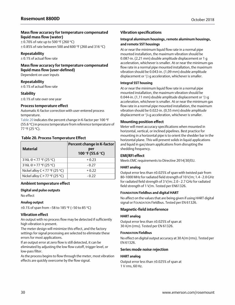
Process temperature effectAutomatic K-factor correction with user-entered process temperature.Table 20 indicates the percent change in K-factor per 100 °F (55.6 °C) in process temperature from reference temperature of 77 °F (25 °C).
Ambient temperature effect
Digital and pulse outputs
No effect
Analog output
±0.1% of span from –58 to 185 °F (–50 to 85 °C)
Vibration effectAn output with no process flow may be detected if sufficiently high vibration is present.The meter design will minimize this effect, and the factory settings for signal processing are selected to eliminate these errors for most applications.If an output error at zero flow is still detected, it can be eliminated by adjusting the low flow cutoff, trigger level, or low-pass filter.As the process begins to flow through the meter, most vibration effects are quickly overcome by the flow signal.
Vibration specifications
Integral aluminum housings, remote aluminum housings, and remote SST housings
At or near the minimum liquid flow rate in a normal pipe mounted installation, the maximum vibration should be 0.087-in. (2,21 mm) double amplitude displacement or 1 g acceleration, whichever is smaller. At or near the minimum gas flow rate in a normal pipe mounted installation, the maximum vibration should be 0.043-in. (1,09 mm) double amplitude displacement or 1/2 g acceleration, whichever is smaller.
Integral SST housing
At or near the minimum liquid flow rate in a normal pipe mounted installation, the maximum vibration should be 0.044-in. (1,11 mm) double amplitude displacement or 1/3 g acceleration, whichever is smaller. At or near the minimum gas flow rate in a normal pipe mounted installation, the maximum vibration should be 0.022-in. (0,55 mm) double amplitude displacement or 1/6 g acceleration, whichever is smaller.
Mounting position effectMeter will meet accuracy specifications when mounted in horizontal, vertical, or inclined pipelines. Best practice for mounting in a horizontal pipe is to orient the shedder bar in the horizontal plane. This will prevent solids in liquid applications and liquid in gas/steam applications from disrupting the shedding frequency.
EMI/RFI effectMeets EMC requirements to Directive 2014/30/EU.
HART analog
Output error less than ±0.025% of span with twisted pair from 80-1000 MHz for radiated field strength of 10 V/m; 1.4 - 2.0 GHz for radiated field strength of 3 V/m; 2.0 - 2.7 GHz for radiated field strength of 1 V/m. Tested per EN61326.
FOUNDATION Fieldbus and digital HART
No affect on the values that are being given if using HART digital signal or FOUNDATION Fieldbus. Tested per EN 61326.
Magnetic-field interference
HART analog
Output error less than ±0.025% of span at 30 A/m (rms). Tested per EN 61326.
FOUNDATION Fieldbus
No effect on digital output accuracy at 30 A/m (rms). Tested per EN 61326.
Series mode noise rejection
HART analog
Output error less than ±0.025% of span at 1 V rms, 60 Hz.
Table 20. Process Temperature Effect
MaterialPercent change in K-factor
per 100 °F (55.6 °C)
316L @ < 77 °F (25 °C) + 0.23
316L @ > 77 °F (25 °C) - 0.27
Nickel alloy C < 77 °F (25 °C) + 0.22
Nickel alloy C > 77 °F (25 °C) - 0.22
30 www.emerson.com/rosemount
Rosemount 8800DOctober 2018
FOUNDATION Fieldbus
No effect on digital output accuracy at 1 V rms, 60 Hz.
Common mode noise rejection
HART analog
Output error less than ±0.025% of span at 30 V rms, 60 Hz.
FOUNDATION Fieldbus
No effect on digital output accuracy at 250 V rms, 60 Hz.
Power supply effect
HART analog
Less than 0.005% of span per volt
FOUNDATION Fieldbus
No effect on accuracy.
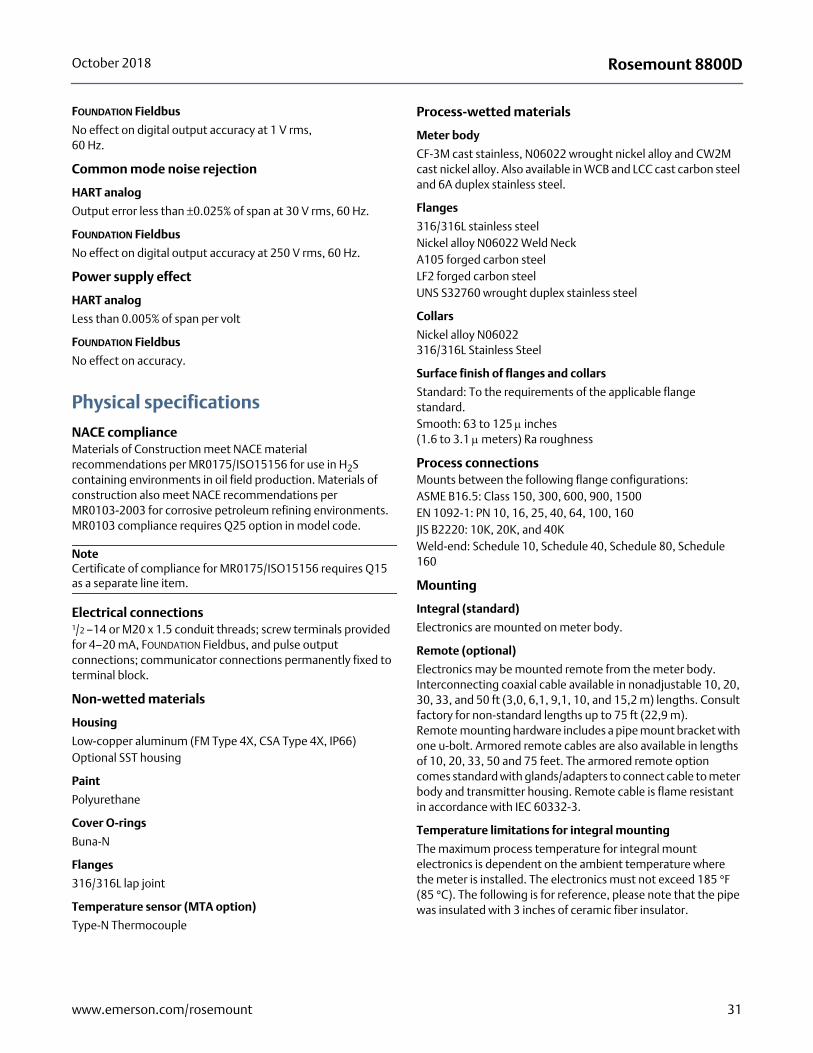
Physical specifications
NACE complianceMaterials of Construction meet NACE material recommendations per MR0175/ISO15156 for use in H2S containing environments in oil field production. Materials of construction also meet NACE recommendations per MR0103-2003 for corrosive petroleum refining environments. MR0103 compliance requires Q25 option in model code.
NoteCertificate of compliance for MR0175/ISO15156 requires Q15 as a separate line item.
Electrical connections1/2 –14 or M20 x 1.5 conduit threads; screw terminals provided for 4–20 mA, FOUNDATION Fieldbus, and pulse output connections; communicator connections permanently fixed to terminal block.
Non-wetted materials
Housing
Low-copper aluminum (FM Type 4X, CSA Type 4X, IP66)Optional SST housing
Paint
Polyurethane
Cover O-rings
Buna-N
Flanges
316/316L lap joint
Temperature sensor (MTA option)
Type-N Thermocouple
Process-wetted materials
Meter body
CF-3M cast stainless, N06022 wrought nickel alloy and CW2M cast nickel alloy. Also available in WCB and LCC cast carbon steel and 6A duplex stainless steel.
Flanges
316/316L stainless steelNickel alloy N06022 Weld NeckA105 forged carbon steelLF2 forged carbon steelUNS S32760 wrought duplex stainless steel
Collars
Nickel alloy N06022316/316L Stainless Steel
Surface finish of flanges and collars
Standard: To the requirements of the applicable flange standard.Smooth: 63 to 125 inches(1.6 to 3.1 meters) Ra roughness
Process connectionsMounts between the following flange configurations:ASME B16.5: Class 150, 300, 600, 900, 1500EN 1092-1: PN 10, 16, 25, 40, 64, 100, 160JIS B2220: 10K, 20K, and 40KWeld-end: Schedule 10, Schedule 40, Schedule 80, Schedule 160
Mounting
Integral (standard)
Electronics are mounted on meter body.
Remote (optional)
Electronics may be mounted remote from the meter body. Interconnecting coaxial cable available in nonadjustable 10, 20, 30, 33, and 50 ft (3,0, 6,1, 9,1, 10, and 15,2 m) lengths. Consult factory for non-standard lengths up to 75 ft (22,9 m). Remote mounting hardware includes a pipe mount bracket with one u-bolt. Armored remote cables are also available in lengths of 10, 20, 33, 50 and 75 feet. The armored remote option comes standard with glands/adapters to connect cable to meter body and transmitter housing. Remote cable is flame resistant in accordance with IEC 60332-3.
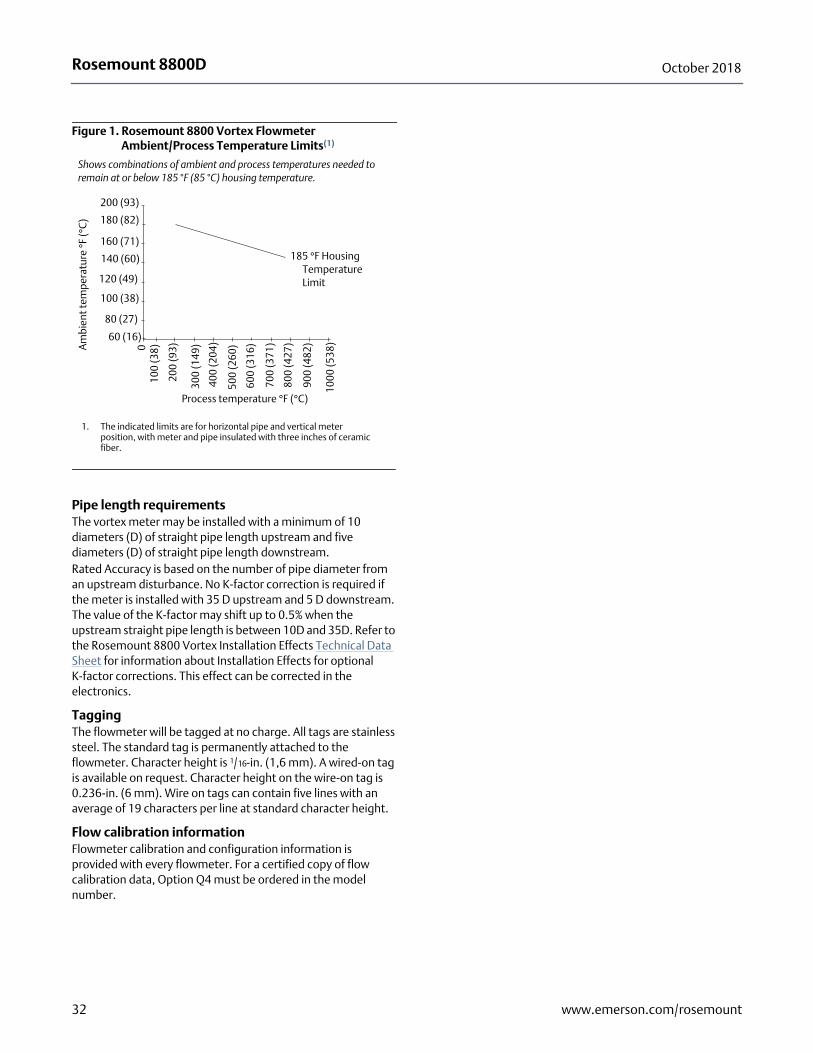
Temperature limitations for integral mounting
The maximum process temperature for integral mount electronics is dependent on the ambient temperature where the meter is installed. The electronics must not exceed 185 °F (85 °C). The following is for reference, please note that the pipe was insulated with 3 inches of ceramic fiber insulator.
31www.emerson.com/rosemount
Rosemount 8800D October 2018
Pipe length requirementsThe vortex meter may be installed with a minimum of 10 diameters (D) of straight pipe length upstream and five diameters (D) of straight pipe length downstream. Rated Accuracy is based on the number of pipe diameter from an upstream disturbance. No K-factor correction is required if the meter is installed with 35 D upstream and 5 D downstream. The value of the K-factor may shift up to 0.5% when the upstream straight pipe length is between 10D and 35D. Refer to the Rosemount 8800 Vortex Installation Effects Technical Data Sheet for information about Installation Effects for optional K-factor corrections. This effect can be corrected in the electronics.
TaggingThe flowmeter will be tagged at no charge. All tags are stainless steel. The standard tag is permanently attached to the flowmeter. Character height is 1/16-in. (1,6 mm). A wired-on tag is available on request. Character height on the wire-on tag is 0.236-in. (6 mm). Wire on tags can contain five lines with an average of 19 characters per line at standard character height.
Flow calibration informationFlowmeter calibration and configuration information is provided with every flowmeter. For a certified copy of flow calibration data, Option Q4 must be ordered in the model number.
Figure 1. Rosemount 8800 Vortex Flowmeter Ambient/Process Temperature Limits(1)
1. The indicated limits are for horizontal pipe and vertical meter position, with meter and pipe insulated with three inches of ceramic fiber.
Shows combinations of ambient and process temperatures needed to remain at or below 185 °F (85 °C) housing temperature.
200 (93)
180 (82)
160 (71)
140 (60)
120 (49)
100 (38)
80 (27)
60 (16)
0
200
(93)
300
(149
)
400
(204
)
500
(260
)
600
(316
)
700
(371
)
800
(427
)
900
(482
)
1000
(538
)
100
(38)A
mbi
ent t
empe
ratu
re °
F (°
C)
Process temperature °F (°C)
185 °F Housing Temperature Limit
32 www.emerson.com/rosemount
Rosemount 8800DOctober 2018
Product Certifications
Flameproof enclosure Ex d protection type in accordance with IEC 60079-1, EN 60079-1Transmitters with Flameproof enclosure type protection shall only be opened when power is removed.
Closing of entries in the device must be carried out using the appropriate Ex d cable gland or blanking plug. Unless otherwise marked on housing, the standard conduit entry thread forms are 1/2-14 NPT.
Type n protection type in accordance with IEC 60079-15, EN60079-15
Closing of entries in the device must be carried out using the appropriate Ex e or Ex n cable gland and metal blanking plug or any appropriate ATEX or IECEx approved cable gland and blanking plug with IP66 rating certified by an EU approved certification body.
European Directive InformationThe CE Declaration of Conformity for all applicable European directives for this product can be found on our website at www.emerson.com/rosemount. A hard copy may be obtained by contacting our local sales office.
ATEX DirectiveEmerson Process Management complies with the ATEX Directive.
European Pressure Equipment Directive (PED)
Rosemount 8800D Vortex Flowmeter Line Size 40 mm to 300 mm
Certificate Number 4741-2014-CE-HOU-DNV 0575 or 2460
Module H Conformity Assessment
Mandatory CE-marking for flowmeters in accordance with Article 15 of the PED can be found on the flowtube body.
Flowmeter categories I – III use module H for conformity assessment procedures.
Rosemount 8800D Vortex Flowmeter Line Size 15 mm and 25 mm
Sound Engineering Practice (SEP)Flowmeters that are SEP are outside the scope of PED and cannot be marked for compliance with PED.
Hazardous Location Certifications
US and Canadian Certifications
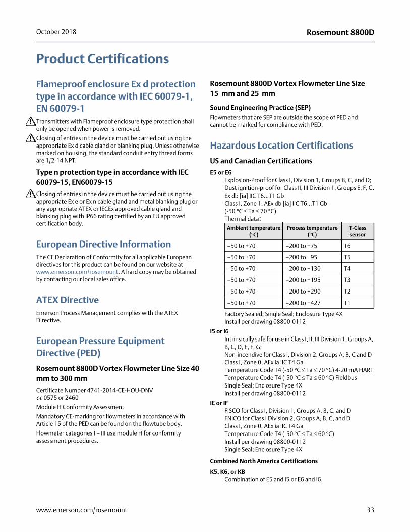
E5 or E6Explosion-Proof for Class I, Division 1, Groups B, C, and D;Dust ignition-proof for Class II, III Division 1, Groups E, F, G.Ex db [ia] IIC T6...T1 GbClass I, Zone 1, AEx db [ia] IIC T6...T1 Gb (-50 °C ≤ Ta ≤ 70 °C)Thermal data:
Factory Sealed; Single Seal; Enclosure Type 4XInstall per drawing 08800-0112
I5 or I6 Intrinsically safe for use in Class I, II, III Division 1, Groups A, B, C, D, E, F, G;Non-incendive for Class I, Division 2, Groups A, B, C and DClass I, Zone 0, AEx ia IIC T4 GaTemperature Code T4 (-50 °C Ta 70 °C) 4-20 mA HARTTemperature Code T4 (-50 °C Ta 60 °C) FieldbusSingle Seal; Enclosure Type 4XInstall per drawing 08800-0112
IE or IFFISCO for Class I, Division 1, Groups A, B, C, and DFNICO for Class I Division 2, Groups A, B, C, and DClass I, Zone 0, AEx ia IIC T4 GaTemperature Code T4 (-50 °C Ta 60 °C)Install per drawing 08800-0112Single Seal; Enclosure Type 4X
Combined North America Certifications
K5, K6, or KBCombination of E5 and I5 or E6 and I6.
Ambient temperature (°C)
Process temperature (°C)
T-Class sensor
–50 to +70 –200 to +75 T6
–50 to +70 –200 to +95 T5
–50 to +70 –200 to +130 T4
–50 to +70 –200 to +195 T3
–50 to +70 –200 to +290 T2
–50 to +70 –200 to +427 T1
33www.emerson.com/rosemount
Rosemount 8800D October 2018
Special Conditions for Safe Use (X):
1. The Flowmeter shall be provided with special fasteners of property class A2-70 or A4-70.
2. For information regarding the dimensions of the flameproof joints the manufacturer shall be contacted.
3. When fitted with the 90V transient suppressors, the equipment is not capable of passing the 500V insulation test. This must be taken into account upon installation.
4. When the equipment is installed, precautions shall be taken to ensure the ambient temperature of the transmitter lies between -50 °C to +70°C, taking into account process fluid effects. If the ambient temperature is outside this range remote transmitters shall be used.
5. Units marked with “Warning: Electrostatic Charging Hazard” may use non-conductive paint thicker than 0.2mm. Precautions shall be taken to avoid ignition due to electrostatic charge on the enclosure.
6. The enclosure may be made from aluminum alloy and given a protective polyurethane paint finish; however, care should be taken to protect it from impact or abrasion when located in Zone 0. The polyurethane paint finish may constitute an electrostatic hazard and must only be cleaned with a damp cloth.
European Certifications
ATEX Intrinsic Safety
EN 60079-0: 2012 + A11: 2013EN 60079-11: 2012
I1 Certification No. Baseefa05ATEX0084X ATEX Marking
II 1 G Ex ia IIC T4 Ga (-60 °C Ta 70 °C) 4-20 mA HART II 1 G Ex ia IIC T4 Ga (-60 °C Ta 60 °C) Fieldbus
2460
ATEX FISCO
IA Certification No. Baseefa05ATEX0084XATEX Marking
II 1 G Ex ia IIC T4 Ga (-60 °C Ta 60 °C) 2460
Special Conditions for Safe Use (X):
1. When fitted with 90V transient suppressors (T1 option), the equipment is not capable of passing the 500V isolation test. This must be taken into account upon installation.
2. The enclosure may be made from aluminum alloy and given a protective polyurethane paint finish; however, care should be taken to protect it from impact or abrasion when located in Zone 0 environment. The polyurethane paint finish may constitute an electrostatic hazard and must only be cleaned with a damp cloth.
3. When the equipment is installed, particular precautions must be taken to ensure taking into account the effect of process fluid temperature, that the ambient temperature of the electrical housing of the equipment meets the marked protection type temperature range.
ATEX Type n Certification
EN 60079-0: 2012 + A11: 2013EN 60079-11: 2012EN 60079-15: 2010
N1 Certification No. Baseefa05ATEX0085XATEX Marking
II 3 G Ex nA ic IIC T5 Gc (-50 °C Ta 70 °C) 4-20 mA HART
II 3 G Ex nA ic IIC T5 Gc (-50 °C Ta 60 °C) FieldbusMaximum Working Voltage = 42 VDC 4-20 mA HARTMaximum Working Voltage = 32 VDC Fieldbus
Special Conditions for Safe Use (X):
1. When fitted with 90V transient suppressors (T1 Option), the equipment is not capable of passing the 500V isolation test. This must be taken into account upon installation.
2. The enclosure may be made from aluminum alloy with a protective polyurethane paint finish. The polyurethane paint finish may constitute and electrostatic hazard and must only be cleaned with a damp cloth.
3. When the equipment is installed, particular precautions must be taken to ensure, taking into account the effect of process fluid temperature, that the ambient temperature of the electrical housing of the equipment meets the marked protection type temperature range.
ATEX Dust Certification
EN 60079-0: 2012 + A11: 2013EN 60079-31: 2014
ND Certificate: BaseefaATEX17.0020X II 2 D Ex tb IIIC T85°C Db (-20 °C Ta 70 °C) 2460
Maximum Working Voltage = 42 VDC 4-20 mA HARTMaximum Working Voltage = 32 VDC Fieldbus
4-20 mA HART entity parameters
Fieldbus entity parameters
FISCO input parameters
Ui = 30 VDC Ui = 30 VDC Ui = 17.5 VDC
Ii(1)
1. Total for transmitter.
= 185 mA Ii(1) = 300 mA Ii
(1) = 380 mA
Pi(1) = 1.0 W Pi
(1) = 1.3 W Pi(1) = 5.32 W
Ci = 0 F Ci = 0 F Ci = 0 F
Li = 0.97mH Li < 10 H Li < 10 H
34 www.emerson.com/rosemount
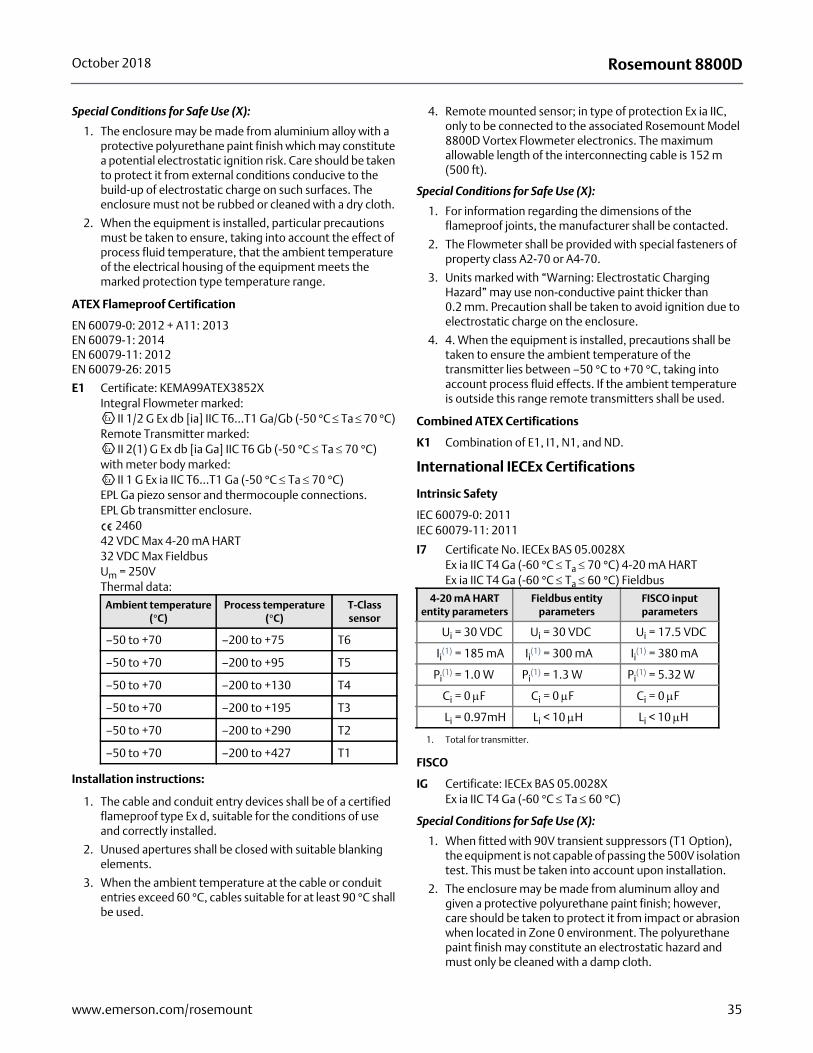
Rosemount 8800DOctober 2018
Special Conditions for Safe Use (X):
1. The enclosure may be made from aluminium alloy with a protective polyurethane paint finish which may constitute a potential electrostatic ignition risk. Care should be taken to protect it from external conditions conducive to the build-up of electrostatic charge on such surfaces. The enclosure must not be rubbed or cleaned with a dry cloth.
2. When the equipment is installed, particular precautions must be taken to ensure, taking into account the effect of process fluid temperature, that the ambient temperature of the electrical housing of the equipment meets the marked protection type temperature range.
ATEX Flameproof Certification
EN 60079-0: 2012 + A11: 2013 EN 60079-1: 2014 EN 60079-11: 2012EN 60079-26: 2015
E1 Certificate: KEMA99ATEX3852XIntegral Flowmeter marked:
II 1/2 G Ex db [ia] IIC T6...T1 Ga/Gb (-50 °C Ta 70 °C) Remote Transmitter marked:
II 2(1) G Ex db [ia Ga] IIC T6 Gb (-50 °C Ta 70 °C)with meter body marked:
II 1 G Ex ia IIC T6...T1 Ga (-50 °C Ta 70 °C)EPL Ga piezo sensor and thermocouple connections.EPL Gb transmitter enclosure.
246042 VDC Max 4-20 mA HART32 VDC Max FieldbusUm = 250VThermal data:
Installation instructions:
1. The cable and conduit entry devices shall be of a certified flameproof type Ex d, suitable for the conditions of use and correctly installed.
2. Unused apertures shall be closed with suitable blanking elements.
3. When the ambient temperature at the cable or conduit entries exceed 60 °C, cables suitable for at least 90 °C shall be used.
4. Remote mounted sensor; in type of protection Ex ia IIC, only to be connected to the associated Rosemount Model 8800D Vortex Flowmeter electronics. The maximum allowable length of the interconnecting cable is 152 m (500 ft).
Special Conditions for Safe Use (X):
1. For information regarding the dimensions of the flameproof joints, the manufacturer shall be contacted.
2. The Flowmeter shall be provided with special fasteners of property class A2-70 or A4-70.
3. Units marked with “Warning: Electrostatic Charging Hazard” may use non-conductive paint thicker than 0.2 mm. Precaution shall be taken to avoid ignition due to electrostatic charge on the enclosure.
4. 4. When the equipment is installed, precautions shall be taken to ensure the ambient temperature of the transmitter lies between –50 °C to +70 °C, taking into account process fluid effects. If the ambient temperature is outside this range remote transmitters shall be used.
Combined ATEX Certifications
K1 Combination of E1, I1, N1, and ND.
International IECEx Certifications
Intrinsic Safety
IEC 60079-0: 2011IEC 60079-11: 2011
I7 Certificate No. IECEx BAS 05.0028XEx ia IIC T4 Ga (-60 °C Ta 70 °C) 4-20 mA HARTEx ia IIC T4 Ga (-60 °C Ta 60 °C) Fieldbus
FISCO
IG Certificate: IECEx BAS 05.0028X Ex ia IIC T4 Ga (-60 °C Ta 60 °C)
Special Conditions for Safe Use (X):
1. When fitted with 90V transient suppressors (T1 Option), the equipment is not capable of passing the 500V isolation test. This must be taken into account upon installation.
2. The enclosure may be made from aluminum alloy and given a protective polyurethane paint finish; however, care should be taken to protect it from impact or abrasion when located in Zone 0 environment. The polyurethane paint finish may constitute an electrostatic hazard and must only be cleaned with a damp cloth.
Ambient temperature (°C)
Process temperature (°C)
T-Class sensor
–50 to +70 –200 to +75 T6
–50 to +70 –200 to +95 T5
–50 to +70 –200 to +130 T4
–50 to +70 –200 to +195 T3
–50 to +70 –200 to +290 T2
–50 to +70 –200 to +427 T1
4-20 mA HART entity parameters
Fieldbus entity parameters
FISCO input parameters
Ui = 30 VDC Ui = 30 VDC Ui = 17.5 VDC
Ii(1)
1. Total for transmitter.
= 185 mA Ii(1) = 300 mA Ii
(1) = 380 mA
Pi(1) = 1.0 W Pi
(1) = 1.3 W Pi(1) = 5.32 W
Ci = 0 F Ci = 0 F Ci = 0 F
Li = 0.97mH Li < 10 H Li < 10 H
35www.emerson.com/rosemount
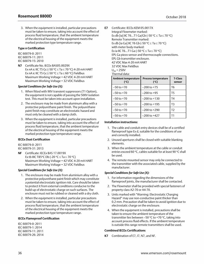
Rosemount 8800D October 2018
3. When the equipment is installed, particular precautions must be taken to ensure, taking into account the effect of process fluid temperature, that the ambient temperature of the electrical housing of the equipment meets the marked protection type temperature range.
Type n Certification
IEC 60079-0: 2011IEC 60079-11: 2011IEC 60079-15: 2010
N7 Certificate No. IECEx BAS05.0029XEx nA ic IIC T5 Gc (-50 °C Ta 70 °C) 4-20 mA HARTEx nA ic IIC T5 Gc (-50 °C Ta 60 °C) FieldbusMaximum Working Voltage = 42 VDC 4-20 mA HARTMaximum Working Voltage = 32 VDC Fieldbus
Special Conditions for Safe Use (X):
1. When fitted with 90V transient suppressors (T1 Option), the equipment is not capable of passing the 500V isolation test. This must be taken into account upon installation.
2. The enclosure may be made from aluminum alloy with a protective polyurethane paint finish. The polyurethane paint finish may constitute an electrostatic hazard and must only be cleaned with a damp cloth.
3. When the equipment is installed, particular precautions must be taken to ensure, taking into account the effect of process fluid temperature, that the ambient temperature of the electrical housing of the equipment meets the marked protection type temperature range.
IECEx Dust Certification
IEC 60079-0: 2011IEC 60079-31: 2013
NF Certificate: IECEx BAS 17.0019XEx tb IIIC T85°C Db (-20 °C Ta 70 °C)Maximum Working Voltage = 42 VDC 4-20 mA HARTMaximum Working Voltage = 32 VDC Fieldbus
Special Conditions for Safe Use (X):
1. The enclosure may be made from aluminium alloy with a protective polyurethane paint finish which may constitute a potential electrostatic ignition risk. Care should be taken to protect it from external conditions conducive to the build-up of electrostatic charge on such surfaces. The enclosure must not be rubbed or cleaned with a dry cloth.
2. When the equipment is installed, particular precautions must be taken to ensure, taking into account the effect of process fluid temperature, that the ambient temperature of the electrical housing of the equipment meets the marked protection type temperature range.
IECEx Flameproof Certification
IEC 60079-0: 2011IEC 60079-1: 2014IEC 60079-11: 2011IEC 60079-26: 2014
E7 Certificate: IECEx KEM 05.0017X Integral Flowmeter marked:Ex db [ia] IIC T6...T1 Ga/Gb (-50 °C Ta 70 °C)Remote Transmitter marked:Ex db [ia Ga] IIC T6 Gb (-50 °C Ta 70 °C)with meter body marked:Ex ia IIC T6...T1 Ga (-50 °C Ta 70 °C)EPL Ga piezo sensor and thermocouple connections.EPL Gb transmitter enclosure.42 VDC Max 4-20 mA HART32 VDC Max FieldbusUm = 250VThermal data:
Installation instructions:
1. The cable and conduit entry devices shall be of a certified flameproof type Ex d, suitable for the conditions of use and correctly installed.
2. Unused apertures shall be closed with suitable blanking elements.
3. When the ambient temperature at the cable or conduit entries exceed 60 °C, cables suitable for at least 90 °C shall be used.
4. The remote mounted sensor may only be connected to the transmitter with the associated cable, supplied by the manufacturer.
Special Conditions for Safe Use (X):
1. For information regarding the dimensions of the flameproof joints, the manufacturer shall be contacted.
2. The Flowmeter shall be provided with special fasteners of property class A2-70 or A4-70.
3. Units marked with “Warning: Electrostatic Charging Hazard” may use non-conductive paint thicker than 0.2 mm. Precaution shall be taken to avoid ignition due to electrostatic charge on the enclosure.
4. When the equipment is installed, precautions shall be taken to ensure the ambient temperature of the transmitter lies between –50 °C to +70 °C, taking into account process fluid effects. If the ambient temperature is outside this range remote transmitters shall be used.
Combined IECEx Certifications
K7 Combination of E7, I7, N7, and NF.
Ambient temperature (°C)
Process temperature (°C)
T-Class sensor
–50 to +70 –200 to +75 T6
–50 to +70 –200 to +95 T5
–50 to +70 –200 to +130 T4
–50 to +70 –200 to +195 T3
–50 to +70 –200 to +290 T2
–50 to +70 –200 to +427 T1
36 www.emerson.com/rosemount
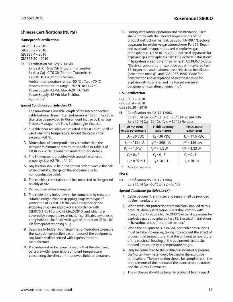
Rosemount 8800DOctober 2018
Chinese Certifications (NEPSI)
Flameproof Certification
GB3836.1 – 2010GB3836.2 – 2010GB3836.4 – 2010GB3836.20 – 2010
E3 Certification No. GYJ17.1404XEx ia / d IIC T6 Ga/Gb (Integral Transmitter)Ex d [ia Ga] IIC T6 Gb (Remote Transmitter)Ex ia IIC T6 Ga (Remote Sensor)Ambient temperature range: -50 °C Ta +70 °CProcess temperature range: -202 °C to +427 °CPower Supply: 42 Vdc Max 4-20 mA HARTPower Supply: 32 Vdc Max FieldbusUm = 250V
Special Conditions for Safe Use (X):
1. The maximum allowable length of the interconnecting cable between transmitter and sensor is 152 m. The cable shall also be provided by Rosemount Inc., or by Emerson Process Management Flow Technologies Co., Ltd.
2. Suitable heat-resisting cables rated at least +80 °C shall be used when the temperature around the cable entry exceeds +60 °C.
3. Dimensions of flameproof joints are other than the relevant minimum or maximum specified in Table 3 of GB3836.2-2010. Contact manufacturer for details.
4. The Flowmeter is provided with special fasteners of property class A2-70 or A4-70.
5. Any friction should be prevented in order to avoid the risk of electrostatic charge on the enclosure due to non-conductive paint.
6. The earthing terminal should be connected to the ground reliably at site.
7. Do not open when energized.
8. The cable entry holes have to be connected by means of suitable entry device or stopping plugs with type of protection of Ex d IIC Gb the cable entry device and stopping plugs are approved in accordance with GB3836.1-2010 and GB3836.2-2010, and which are covered by a separate examination certificate, any unused entry hole is to be fitted with type of protection of Ex d IIC Gb flameproof stopping plug.
9. Users are forbidden to change the configuration to ensure the explosion protection performance of the equipment. Any faults shall be settled with experts from the manufacturer.
10. Precautions shall be taken to ensure that the electronic parts are within permissible ambient temperature considering the effect of the allowed fluid temperature.
11. During installation, operation and maintenance, users shall comply with the relevant requirements of the product instruction manual, GB3836.13-1997 “Electrical apparatus for explosive gas atmospheres Part 13: Repair and overhaul for apparatus used in explosive gas atmospheres”, GB3836.15-2000 “Electrical apparatus for explosive gas atmospheres Part 15: Electrical installations in hazardous areas (other than mines)”, GB3836.16-2006 “Electrical apparatus for explosive gas atmospheres Part 16: Inspection and maintenance of electrical installation (other than mines)”, and GB50257-1996 “Code for construction and acceptance of electrical device for explosion atmospheres and fire hazard electrical equipment installation engineering”.
I. S. Certification
GB3836.1 – 2010GB3836.4 – 2010GB3836.20 – 2010
I3 Certification No. GYJ17.1196XEx ia IIC T4 Ga (-60 °C Ta + 70 °C) 4-20 mA HARTEx ia IIC T4 Ga (-60 °C Ta + 60 °C) Fieldbus
FISCO
IH Certification No. GYJ17.1196XEx ia IIC T4 Ga (-60 °C Ta +60 °C)
Special Conditions for Safe Use (X):
1. Cable between transmitter and sensor shall be provided by the manufacturer.
2. When transient protection terminal block applied to this product, during installation, users shall comply with Clause 12.2.4 in GB3836.15-2000 “Electrical apparatus for explosive gas atmospheres Part 15: Electrical installations in hazardous areas (other than mines).”
3. When the equipment is installed, particular precautions must be taken to ensure, taking into account the effect of process fluid temperature, that the ambient temperature of the electrical housing of the equipment meets the marked protection type temperature range..
4. Only be connected to the certified associated apparatus, the Vortex Flowmeter could be used in the explosive atmosphere. The connection should be complied with the requirements of the manual of the associated apparatus and the Vortex Flowmeter.
5. The enclosure should be taken to protect it from impact.
4-20 mA HART entity parameters
Fieldbus entity parameters
FISCO input parameters
Ui = 30 VDC Ui = 30 VDC Ui = 17.5 VDC
Ii(1)
1. Total for transmitter.
= 185 mA Ii(1) = 300 mA Ii
(1) = 380 mA
Pi(1) = 1.0 W Pi
(1) = 1.3 W Pi(1) = 5.32 W
Ci = 0 F Ci = 0 F Ci = 0 F
Li = 0.97mH Li < 10 H Li < 10 H
37www.emerson.com/rosemount
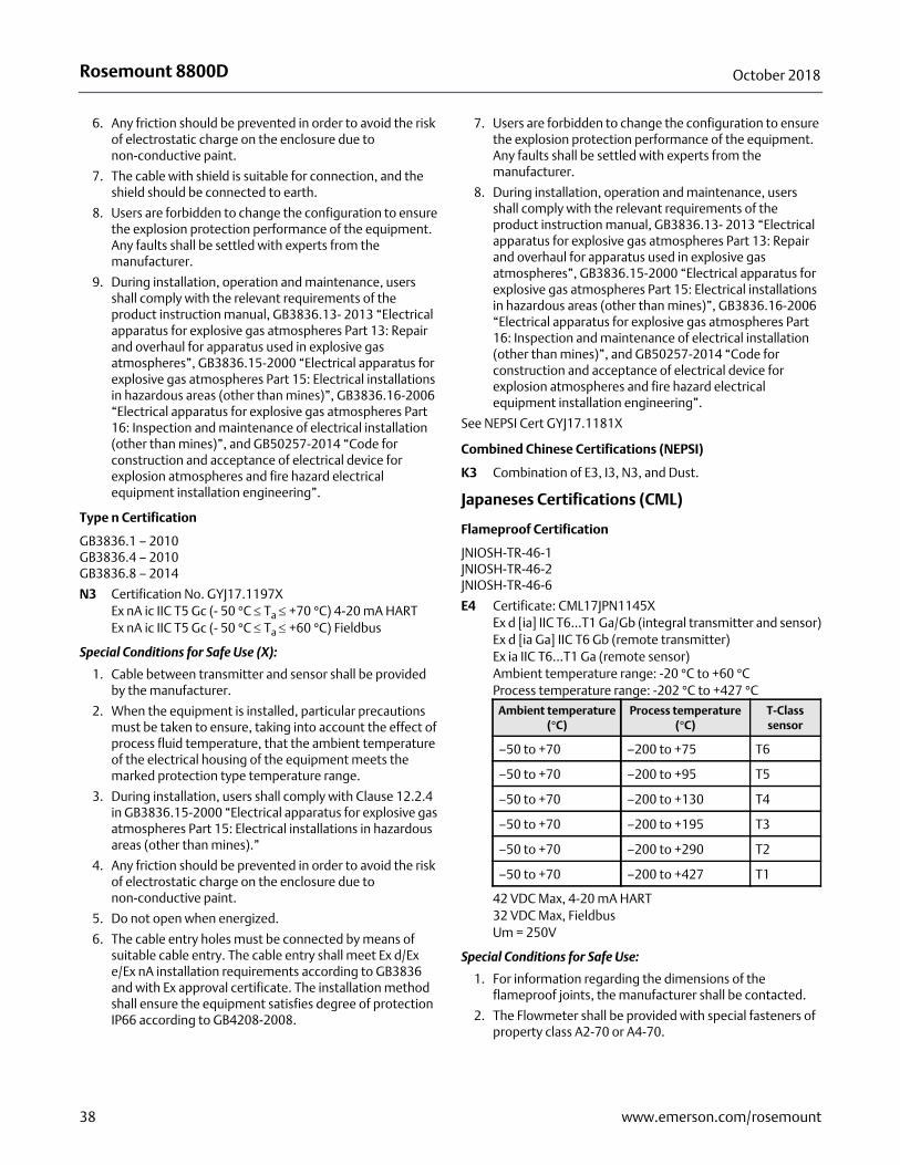
Rosemount 8800D October 2018
6. Any friction should be prevented in order to avoid the risk of electrostatic charge on the enclosure due to non-conductive paint.
7. The cable with shield is suitable for connection, and the shield should be connected to earth.
8. Users are forbidden to change the configuration to ensure the explosion protection performance of the equipment. Any faults shall be settled with experts from the manufacturer.
9. During installation, operation and maintenance, users shall comply with the relevant requirements of the product instruction manual, GB3836.13- 2013 “Electrical apparatus for explosive gas atmospheres Part 13: Repair and overhaul for apparatus used in explosive gas atmospheres”, GB3836.15-2000 “Electrical apparatus for explosive gas atmospheres Part 15: Electrical installations in hazardous areas (other than mines)”, GB3836.16-2006 “Electrical apparatus for explosive gas atmospheres Part 16: Inspection and maintenance of electrical installation (other than mines)”, and GB50257-2014 “Code for construction and acceptance of electrical device for explosion atmospheres and fire hazard electrical equipment installation engineering”.
Type n Certification
GB3836.1 – 2010GB3836.4 – 2010GB3836.8 – 2014
N3 Certification No. GYJ17.1197XEx nA ic IIC T5 Gc (- 50 °C Ta +70 °C) 4-20 mA HARTEx nA ic IIC T5 Gc (- 50 °C Ta +60 °C) Fieldbus
Special Conditions for Safe Use (X):
1. Cable between transmitter and sensor shall be provided by the manufacturer.
2. When the equipment is installed, particular precautions must be taken to ensure, taking into account the effect of process fluid temperature, that the ambient temperature of the electrical housing of the equipment meets the marked protection type temperature range.
3. During installation, users shall comply with Clause 12.2.4 in GB3836.15-2000 “Electrical apparatus for explosive gas atmospheres Part 15: Electrical installations in hazardous areas (other than mines).”
4. Any friction should be prevented in order to avoid the risk of electrostatic charge on the enclosure due to non-conductive paint.
5. Do not open when energized.
6. The cable entry holes must be connected by means of suitable cable entry. The cable entry shall meet Ex d/Ex e/Ex nA installation requirements according to GB3836 and with Ex approval certificate. The installation method shall ensure the equipment satisfies degree of protection IP66 according to GB4208-2008.
7. Users are forbidden to change the configuration to ensure the explosion protection performance of the equipment. Any faults shall be settled with experts from the manufacturer.
8. During installation, operation and maintenance, users shall comply with the relevant requirements of the product instruction manual, GB3836.13- 2013 “Electrical apparatus for explosive gas atmospheres Part 13: Repair and overhaul for apparatus used in explosive gas atmospheres”, GB3836.15-2000 “Electrical apparatus for explosive gas atmospheres Part 15: Electrical installations in hazardous areas (other than mines)”, GB3836.16-2006 “Electrical apparatus for explosive gas atmospheres Part 16: Inspection and maintenance of electrical installation (other than mines)”, and GB50257-2014 “Code for construction and acceptance of electrical device for explosion atmospheres and fire hazard electrical equipment installation engineering”.
See NEPSI Cert GYJ17.1181X
Combined Chinese Certifications (NEPSI)
K3 Combination of E3, I3, N3, and Dust.
Japaneses Certifications (CML)
Flameproof Certification
JNIOSH-TR-46-1JNIOSH-TR-46-2JNIOSH-TR-46-6
E4 Certificate: CML17JPN1145XEx d [ia] IIC T6...T1 Ga/Gb (integral transmitter and sensor)Ex d [ia Ga] IIC T6 Gb (remote transmitter) Ex ia IIC T6...T1 Ga (remote sensor)Ambient temperature range: -20 °C to +60 °CProcess temperature range: -202 °C to +427 °C
42 VDC Max, 4-20 mA HART32 VDC Max, FieldbusUm = 250V
Special Conditions for Safe Use:
1. For information regarding the dimensions of the flameproof joints, the manufacturer shall be contacted.
2. The Flowmeter shall be provided with special fasteners of property class A2-70 or A4-70.
Ambient temperature (°C)
Process temperature (°C)
T-Class sensor
–50 to +70 –200 to +75 T6
–50 to +70 –200 to +95 T5
–50 to +70 –200 to +130 T4
–50 to +70 –200 to +195 T3
–50 to +70 –200 to +290 T2
–50 to +70 –200 to +427 T1
38 www.emerson.com/rosemount
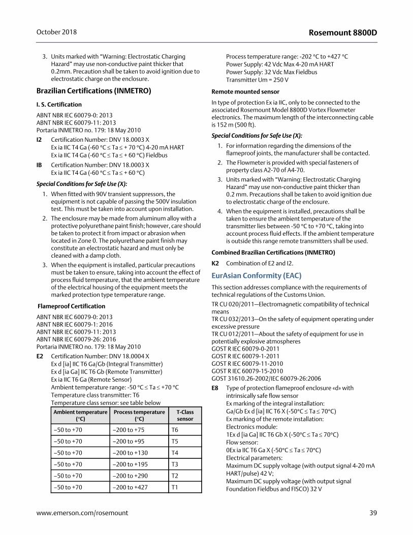
Rosemount 8800DOctober 2018
3. Units marked with “Warning: Electrostatic Charging Hazard” may use non-conductive paint thicker that 0.2mm. Precaution shall be taken to avoid ignition due to electrostatic charge on the enclosure.
Brazilian Certifications (INMETRO)
I. S. Certification
ABNT NBR IEC 60079-0: 2013ABNT NBR IEC 60079-11: 2013Portaria INMETRO no. 179: 18 May 2010
I2 Certification Number: DNV 18.0003 XEx ia IIC T4 Ga (-60 °C Ta + 70 °C) 4-20 mA HARTEx ia IIC T4 Ga (-60 °C Ta + 60 °C) Fieldbus
IB Certification Number: DNV 18.0003 XEx ia IIC T4 Ga (-60 °C Ta + 60 °C)
Special Conditions for Safe Use (X):
1. When fitted with 90V transient suppressors, the equipment is not capable of passing the 500V insulation test. This must be taken into account upon installation.
2. The enclosure may be made from aluminum alloy with a protective polyurethane paint finish; however, care should be taken to protect it from impact or abrasion when located in Zone 0. The polyurethane paint finish may constitute an electrostatic hazard and must only be cleaned with a damp cloth.
3. When the equipment is installed, particular precautions must be taken to ensure, taking into account the effect of process fluid temperature, that the ambient temperature of the electrical housing of the equipment meets the marked protection type temperature range.
Flameproof Certification
ABNT NBR IEC 60079-0: 2013ABNT NBR IEC 60079-1: 2016ABNT NBR IEC 60079-11: 2013ABNT NBR IEC 60079-26: 2016Portaria INMETRO no. 179: 18 May 2010
E2 Certification Number: DNV 18.0004 XEx d [ia] IIC T6 Ga/Gb (Integral Transmitter)Ex d [ia Ga] IIC T6 Gb (Remote Transmitter)Ex ia IIC T6 Ga (Remote Sensor)Ambient temperature range: -50 °C Ta +70 °CTemperature class transmitter: T6Temperature class sensor: see table below
Process temperature range: -202 °C to +427 °CPower Supply: 42 Vdc Max 4-20 mA HARTPower Supply: 32 Vdc Max FieldbusTransmitter Um = 250 V
Remote mounted sensor
In type of protection Ex ia IIC, only to be connected to the associated Rosemount Model 8800D Vortex Flowmeter electronics. The maximum length of the interconnecting cable is 152 m (500 ft).
Special Conditions for Safe Use (X):
1. For information regarding the dimensions of the flameproof joints, the manufacturer shall be contacted.
2. The Flowmeter is provided with special fasteners of property class A2-70 of A4-70.
3. Units marked with “Warning: Electrostatic Charging Hazard” may use non-conductive paint thicker than 0.2 mm. Precautions shall be taken to avoid ignition due to electrostatic charge of the enclosure.
4. When the equipment is installed, precautions shall be taken to ensure the ambient temperature of the transmitter lies between -50 °C to +70 °C, taking into account process fluid effects. If the ambient temperature is outside this range remote transmitters shall be used.
Combined Brazilian Certifications (INMETRO)
K2 Combination of E2 and I2.
EurAsian Conformity (EAC)
This section addresses compliance with the requirements of technical regulations of the Customs Union.
TR CU 020/2011—Electromagnetic compatibility of technical meansTR CU 032/2013—On the safety of equipment operating under excessive pressureTR CU 012/2011—About the safety of equipment for use in potentially explosive atmospheresGOST R IEC 60079-0-2011GOST R IEC 60079-1-2011GOST R IEC 60079-11-2010GOST R IEC 60079-15-2010GOST 31610.26-2002/IEC 60079-26:2006
E8 Type of protection flameproof enclosure «d» with intrinsically safe flow sensorEx marking of the integral installation:Ga/Gb Ex d [ia] IIC T6 X (-50°C Ta 70°C)Ex marking of the remote installation:Electronics module:1Ex d [ia Ga] IIC T6 Gb X (-50°C Ta 70°C)Flow sensor:0Ex ia IIC T6 Ga X (-50°C Ta 70°C)Electrical parameters:Maximum DC supply voltage (with output signal 4-20 mA HART/pulse) 42 V;Maximum DC supply voltage (with output signal Foundation Fieldbus and FISCO) 32 V
Ambient temperature (°C)
Process temperature (°C)
T-Class sensor
–50 to +70 –200 to +75 T6
–50 to +70 –200 to +95 T5
–50 to +70 –200 to +130 T4
–50 to +70 –200 to +195 T3
–50 to +70 –200 to +290 T2
–50 to +70 –200 to +427 T1
39www.emerson.com/rosemount
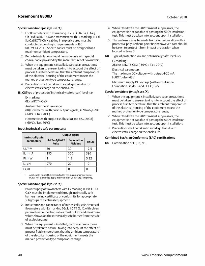
Rosemount 8800D October 2018
Special conditions for safe use (X):
1. For flowmeters with Ex marking 0Ex ia IIC T6 Ga X, Ga / Gb Ex d [ia] IIC T6 X and transmitter with Ex marking 1Ex d [ia Ga] IIC T6 Gb X cabling in explosive area must be conducted according to requirements of IEC 60079-14-2011. Sheath cables must be designed for a maximum ambient temperature.
2. Remote installation should be made only with special coaxial cable provided by the manufacturer of flowmeters.
3. When the equipment is installed, particular precautions must be taken to ensure, taking into account the effect of process fluid temperature, that the ambient temperature of the electrical housing of the equipment meets the marked protection type temperature range.
4. Precautions shall be taken to avoid ignition due to electrostatic charge on the enclosure.
I8, G8Type of protection "intrinsically safe circuit" level «ia»
Ex marking: 0Ex ia IIC T4 Ga X
Ambient temperature range:(I8) Flowmeters with pulse output signals, 4-20 mA /HART (-60°C Ta 70°C)
Flowmeters with output Fieldbus (I8) and FISCO (G8) (-60°C Ta 60°C)
Input intrinsically safe parameters:
Special conditions for safe use (X):
1. Power supply of flowmeters with Ex marking 0Ex ia IIC T4 Ga X must be implemented through intrinsically safe barriers having certificate of conformity for appropriate subgroups of electrical equipment.
2. Inductance and capacitance of intrinsically safe circuits of flowmeters with Ex marking 0Ex ia IIC T4 Ga X, with given parameters connecting cables must not exceed maximum values shown on the intrinsically safe barrier from the side of explosive zone.
3. When the equipment is installed, particular precautions must be taken to ensure, taking into account the effect of process fluid temperature, that the ambient temperature of the electrical housing of the equipment meets the marked protection type temperature range.
4. When fitted with the 90V transient suppressors, the equipment is not capable of passing the 500V insulation test. This must be taken into account upon installation.
5. The enclosure may be made from aluminium alloy with a protective polyurethane paint finish; however, care should be taken to protect it from impact or abrasion when located in Zone 0.
N8 Type of protection «n» and "intrinsically safe" level «ic»
Ex marking:2Ex nA ic IIC T5 Gc X (-50°C Ta 70°C)
Electrical parameters:The maximum DC voltage (with output 4-20 mA HART/pulse) 42V;
Maximum supply DC voltage (with output signal Foundation Fieldbus and FISCO) 32V
Special conditions for safe use (X):
1. When the equipment is installed, particular precautions must be taken to ensure, taking into account the effect of process fluid temperature, that the ambient temperature of the electrical housing of the equipment meets the marked protection type temperature range;
2. When fitted with the 90V transient suppressors, the equipment is not capable of passing the 500V insulation test. This must be taken into account upon installation;
3. Precautions shall be taken to avoid ignition due to electrostatic charge on the enclosure.
Combined EurAsian Conformity (EAC) certifications
K8 Combination of E8, I8, N8.
Intrinsically safe parameters
Output signal
4-20mA/HARTPulse
Foundation Fieldbus
FISCO
Ui,(1) V
1. Applicable values Ui, Ii are limited by the maximum input power Pi. It is not allowed to apply max values of Ui, Ii at the same time.
30 30 17.5
Ii,(1) mA 185 300 380
Pi,(1) W 1 1.3 5.32
Li, uH 970 20 10
Ci, nF 0 0 0
40 www.emerson.com/rosemount
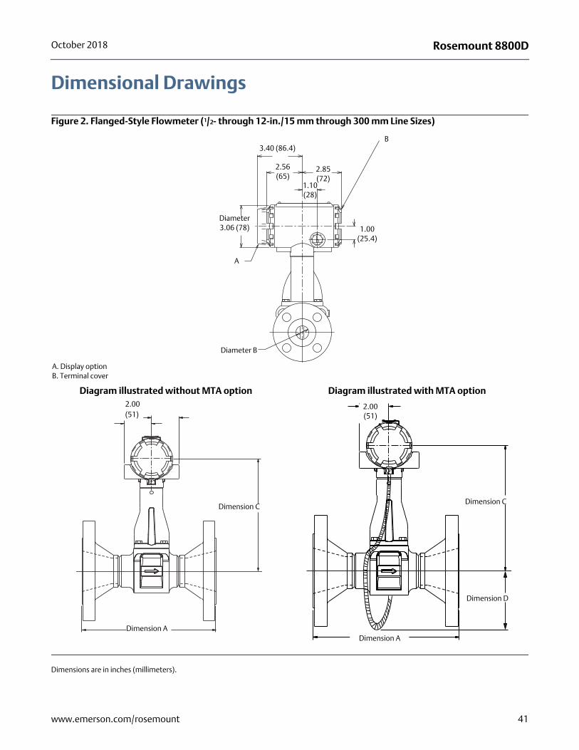
Rosemount 8800DOctober 2018
Dimensional Drawings
Figure 2. Flanged-Style Flowmeter (1/2- through 12-in./15 mm through 300 mm Line Sizes)
Dimensions are in inches (millimeters).
A. Display optionB. Terminal cover
B
A
Diameter 3.06 (78)
Diameter B
3.40 (86.4)
2.56 (65)
2.85 (72)
1.10 (28)
1.00 (25.4)
2.00(51)
Dimension A
Dimension C
Diagram illustrated without MTA option
Dimension C
Dimension A
2.00 (51)
Dimension D
Diagram illustrated with MTA option
41www.emerson.com/rosemount
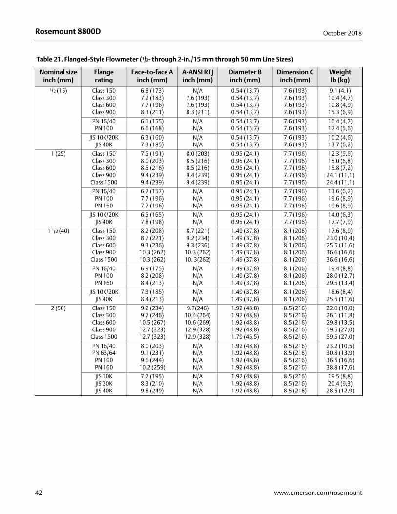
Rosemount 8800D October 2018
Table 21. Flanged-Style Flowmeter (1/2- through 2-in./15 mm through 50 mm Line Sizes)
Nominal size inch (mm)
Flange rating
Face-to-face A inch (mm)
A-ANSI RTJ inch (mm)
Diameter B inch (mm)
Dimension C inch (mm)
Weight lb (kg)
1/2 (15) Class 150Class 300Class 600Class 900
6.8 (173)7.2 (183)7.7 (196)8.3 (211)
N/A7.6 (193)7.6 (193)8.3 (211)
0.54 (13,7)0.54 (13,7)0.54 (13,7)0.54 (13,7)
7.6 (193)7.6 (193)7.6 (193)7.6 (193)
9.1 (4,1)10.4 (4,7)10.8 (4,9)15.3 (6,9)
PN 16/40PN 100
6.1 (155)6.6 (168)
N/AN/A
0.54 (13,7)0.54 (13,7)
7.6 (193)7.6 (193)
10.4 (4,7)12.4 (5,6)
JIS 10K/20KJIS 40K
6.3 (160)7.3 (185)
N/AN/A
0.54 (13,7)0.54 (13,7)
7.6 (193)7.6 (193)
10.2 (4,6)13.7 (6,2)
1 (25) Class 150Class 300Class 600Class 900
Class 1500
7.5 (191)8.0 (203)8.5 (216)9.4 (239)9.4 (239)
8.0 (203)8.5 (216)8.5 (216)9.4 (239)9.4 (239)
0.95 (24,1)0.95 (24,1)0.95 (24,1)0.95 (24,1)0.95 (24,1)
7.7 (196)7.7 (196)7.7 (196)7.7 (196)7.7 (196)
12.3 (5,6)15.0 (6,8)15.8 (7,2)
24.1 (11,1)24.4 (11,1)
PN 16/40PN 100PN 160
6.2 (157)7.7 (196)7.7 (196)
N/AN/AN/A
0.95 (24,1)0.95 (24,1)0.95 (24,1)
7.7 (196)7.7 (196)7.7 (196)
13.6 (6,2)19.6 (8,9)19.6 (8,9)
JIS 10K/20KJIS 40K
6.5 (165)7.8 (198)
N/AN/A
0.95 (24,1)0.95 (24,1)
7.7 (196)7.7 (196)
14.0 (6,3)17.7 (7,9)
1 1/2 (40) Class 150Class 300Class 600Class 900
Class 1500
8.2 (208)8.7 (221)9.3 (236)
10.3 (262)10.3 (262)
8.7 (221)9.2 (234)9.3 (236)
10.3 (262)10. 3(262)
1.49 (37,8)1.49 (37,8)1.49 (37,8)1.49 (37,8)1.49 (37,8)
8.1 (206)8.1 (206)8.1 (206)8.1 (206)8.1 (206)
17.6 (8,0)23.0 (10,4)25.5 (11,6)36.6 (16,6)36.6 (16,6)
PN 16/40PN 100PN 160
6.9 (175)8.2 (208)8.4 (213)
N/AN/AN/A
1.49 (37,8)1.49 (37,8)1.49 (37,8)
8.1 (206)8.1 (206)8.1 (206)
19.4 (8,8)28.0 (12,7)29.5 (13,4)
JIS 10K/20KJIS 40K
7.3 (185)8.4 (213)
N/AN/A
1.49 (37,8)1.49 (37,8)
8.1 (206)8.1 (206)
18.6 (8,4)25.5 (11,6)
2 (50) Class 150Class 300Class 600Class 900
Class 1500
9.2 (234)9.7 (246)
10.5 (267)12.7 (323)12.7 (323)
9.7(246)10.4 (264)10.6 (269)12.9 (328)12.9 (328)
1.92 (48,8)1.92 (48,8)1.92 (48,8)1.92 (48,8)1.79 (45,5)
8.5 (216)8.5 (216)8.5 (216)8.5 (216)8.5 (216)
22.0 (10,0)26.1 (11,8)29.8 (13,5)59.5 (27,0)59.5 (27,0)
PN 16/40PN 63/64
PN 100PN 160
8.0 (203)9.1 (231)9.6 (244)
10.2 (259)
N/AN/AN/AN/A
1.92 (48,8)1.92 (48,8)1.92 (48,8)1.92 (48,8)
8.5 (216)8.5 (216)8.5 (216)8.5 (216)
23.2 (10,5)30.8 (13,9)36.5 (16,6)38.8 (17,6)
JIS 10KJIS 20KJIS 40K
7.7 (195)8.3 (210)9.8 (249)
N/AN/AN/A
1.92 (48,8)1.92 (48,8)1.92 (48,8)
8.5 (216)8.5 (216)8.5 (216)
19.5 (8,8)20.4 (9,3)
28.5 (12,9)
42 www.emerson.com/rosemount
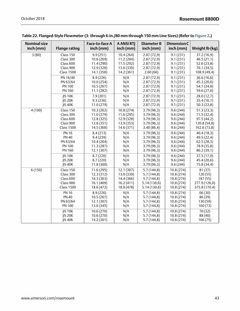
Rosemount 8800DOctober 2018
Table 22. Flanged-Style Flowmeter (3- through 6-in./80 mm through 150 mm Line Sizes) (Refer to Figure 2.)
Nominal size inch (mm) Flange rating
Face-to-face A inch (mm)
A ANSI RTJ inch (mm)
Diameter B inch (mm)
Dimension C inch (mm) Weight lb (kg)
3 (80) Class 150Class 300Class 600Class 900
Class 1500
9.9 (251)10.6 (269)11.4 (290)12.9 (328)14.1 (358)
10.4 (264)11.2 (284)11.5 (292)13.0 (330)14.2 (361)
2.87 (72,9)2.87 (72,9)2.87 (72,9)2.87 (72,9)
2.60 (66)
9.1 (231)9.1 (231)9.1 (231)9.1 (231)9.1 (231)
37.2 (16,9)46.5 (21,1)52.6 (23,8)76.1 (34,5)
108.9 (49,4)
PN 16/40PN 63/64
PN 100PN 160
8.9 (226)10.0 (254)10.5 (267)11.1 (282)
N/AN/AN/AN/A
2.87 (72,9)2.87 (72,9)2.87 (72,9)2.87 (72,9)
9.1 (231)9.1 (231)9.1 (231)9.1 (231)
36.6 (16,6)45.3 (20,6)54.7 (24,8)59.6 (27,0)
JIS 10KJIS 20KJIS 40K
7.9 (201)9.3 (236)
11.0 (279)
N/AN/AN/A
2.87 (72,9)2.87 (72,9)2.87 (72,9)
9.1 (231)9.1 (231)9.1 (231)
28.0 (12,7)35.4 (16,1)50.3 (22,8)
4 (100) Class 150Class 300Class 600Class 900
Class 1500
10.3 (262)11.0 (279)12.8 (325)13.8 (351)14.5 (368)
10.8 (274)11.6 (295)12.9 (328)13.9 (353)14.6 (371)
3.79 (96,3)3.79 (96,3)3.79 (96,3)3.79 (96,3)3.40 (86,4)
9.6 (244)9.6 (244)9.6 (244)9.6 (244)9.6 (244)
51.3 (23,3)71.5 (32,4)97.5 (44,2)
120.8 (54,8)162.6 (73,8)
PN 16PN 40
PN 63/64PN 100PN 160
8.4 (213)9.4 (239)
10.4 (264)11.3 (287)12.1 (307)
N/AN/AN/AN/AN/A
3.79 (96,3)3.79 (96,3)3.79 (96,3)3.79 (96,3)3.79 (96,3)
9.6 (244)9.6 (244)9.6 (244)9.6 (244)9.6 (244)
40.4 (18,3)49.5 (22,4)62.5 (28,3)78.9 (35,8)86.2 (39,1)
JIS 10KJIS 20KJIS 40K
8.7 (220)8.7 (220)
11.8 (300)
N/AN/AN/A
3.79 (96,3)3.79 (96,3)3.79 (96,3)
9.6 (244)9.6 (244)9.6 (244)
37.5 (17,0)45.4 (20,6)75.8 (34,4)
6 (150) Class 150Class 300Class 600Class 900
Class 1500
11.6 (295)12.3 (312)14.3 (363)16.1 (409)18.6 (472)
12.1 (307)13.0 (330)14.4 (366) 16.2 (411)18.8 (478)
5.7 (144,8)5.7 (144,8)5.7 (144,8)
5.14 (130,6)5.14 (130,6)
10.8 (274)10.8 (274)10.8 (274)10.8 (274)10.8 (274)
81 (37)120 (55)187 (55)
277.9 (126,0)375.8 (170.4)
PN 16PN 40
PN 63/64PN 100
8.9 (226)10.5 (267)12.1 (307)13.6 (345)
N/AN/AN/AN/A
5.7 (144,8)5.7 (144,8)5.7 (144,8)5.7 (144,8)
10.8 (274)10.8 (274)10.8 (274)10.8 (274)
66 (30)86 (39)
130 (59)160 (73)
JIS 10KJIS 20KJIS 40K
10.6 (270)10.6 (270)14.2 (361)
N/AN/AN/A
5.7 (144,8)5.7 (144,8)5.7 (144,8)
10.8 (274)10.8 (274)10.8 (274)
70 (32)88 (40)
166 (75)
43www.emerson.com/rosemount
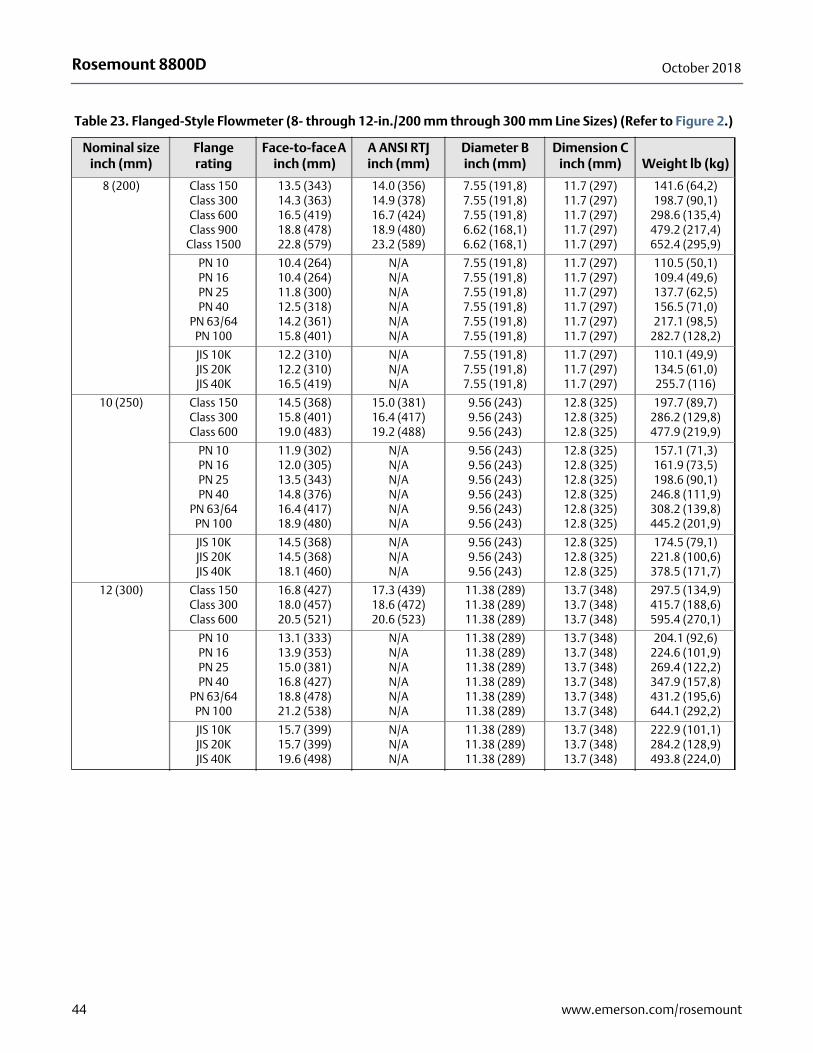
Rosemount 8800D October 2018
Table 23. Flanged-Style Flowmeter (8- through 12-in./200 mm through 300 mm Line Sizes) (Refer to Figure 2.)
Nominal size inch (mm)
Flange rating
Face-to-face A inch (mm)
A ANSI RTJ inch (mm)
Diameter B inch (mm)
Dimension C inch (mm) Weight lb (kg)
8 (200) Class 150Class 300Class 600Class 900
Class 1500
13.5 (343)14.3 (363)16.5 (419)18.8 (478)22.8 (579)
14.0 (356)14.9 (378)16.7 (424)18.9 (480)23.2 (589)
7.55 (191,8)7.55 (191,8)7.55 (191,8)6.62 (168,1)6.62 (168,1)
11.7 (297)11.7 (297)11.7 (297)11.7 (297)11.7 (297)
141.6 (64,2)198.7 (90,1)
298.6 (135,4)479.2 (217,4)652.4 (295,9)
PN 10PN 16PN 25PN 40
PN 63/64PN 100
10.4 (264)10.4 (264)11.8 (300)12.5 (318)14.2 (361)15.8 (401)
N/AN/AN/AN/AN/AN/A
7.55 (191,8)7.55 (191,8)7.55 (191,8)7.55 (191,8)7.55 (191,8)7.55 (191,8)
11.7 (297)11.7 (297)11.7 (297)11.7 (297)11.7 (297)11.7 (297)
110.5 (50,1)109.4 (49,6)137.7 (62,5)156.5 (71,0)217.1 (98,5)
282.7 (128,2)
JIS 10KJIS 20KJIS 40K
12.2 (310)12.2 (310)16.5 (419)
N/AN/AN/A
7.55 (191,8)7.55 (191,8)7.55 (191,8)
11.7 (297)11.7 (297)11.7 (297)
110.1 (49,9)134.5 (61,0)255.7 (116)
10 (250) Class 150Class 300Class 600
14.5 (368)15.8 (401)19.0 (483)
15.0 (381)16.4 (417)19.2 (488)
9.56 (243)9.56 (243)9.56 (243)
12.8 (325)12.8 (325)12.8 (325)
197.7 (89,7)286.2 (129,8)477.9 (219,9)
PN 10PN 16PN 25PN 40
PN 63/64PN 100
11.9 (302)12.0 (305)13.5 (343)14.8 (376)16.4 (417)18.9 (480)
N/AN/AN/AN/AN/AN/A
9.56 (243)9.56 (243)9.56 (243)9.56 (243)9.56 (243)9.56 (243)
12.8 (325)12.8 (325)12.8 (325)12.8 (325)12.8 (325)12.8 (325)
157.1 (71,3)161.9 (73,5)198.6 (90,1)
246.8 (111,9)308.2 (139,8)445.2 (201,9)
JIS 10KJIS 20KJIS 40K
14.5 (368)14.5 (368)18.1 (460)
N/AN/AN/A
9.56 (243)9.56 (243)9.56 (243)
12.8 (325)12.8 (325)12.8 (325)
174.5 (79,1)221.8 (100,6)378.5 (171,7)
12 (300) Class 150Class 300Class 600
16.8 (427)18.0 (457)20.5 (521)
17.3 (439)18.6 (472)20.6 (523)
11.38 (289)11.38 (289)11.38 (289)
13.7 (348)13.7 (348)13.7 (348)
297.5 (134,9)415.7 (188,6)595.4 (270,1)
PN 10PN 16PN 25PN 40
PN 63/64PN 100
13.1 (333)13.9 (353)15.0 (381)16.8 (427)18.8 (478)21.2 (538)
N/AN/AN/AN/AN/AN/A
11.38 (289)11.38 (289)11.38 (289)11.38 (289)11.38 (289)11.38 (289)
13.7 (348)13.7 (348)13.7 (348)13.7 (348)13.7 (348)13.7 (348)
204.1 (92,6)224.6 (101,9)269.4 (122,2)347.9 (157,8)431.2 (195,6)644.1 (292,2)
JIS 10KJIS 20KJIS 40K
15.7 (399)15.7 (399)19.6 (498)
N/AN/AN/A
11.38 (289)11.38 (289)11.38 (289)
13.7 (348)13.7 (348)13.7 (348)
222.9 (101,1)284.2 (128,9)493.8 (224,0)
44 www.emerson.com/rosemount
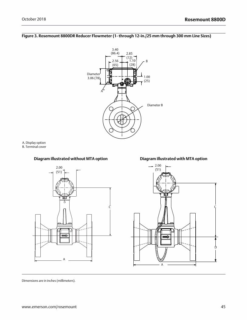
Rosemount 8800DOctober 2018
Figure 3. Rosemount 8800DR Reducer Flowmeter (1- through 12-in./25 mm through 300 mm Line Sizes)
Dimensions are in inches (millimeters).
A. Display optionB. Terminal cover
Diameter B
A
1.00 (25)
3.40 (86.4) 2.85
(72)2.56 (65)
1.10 (28)
Diameter3.06 (78)
B
2.00(51)
A
C
Diagram illustrated without MTA option
C
A
2.00 (51)
D
Diagram illustrated with MTA option
45www.emerson.com/rosemount
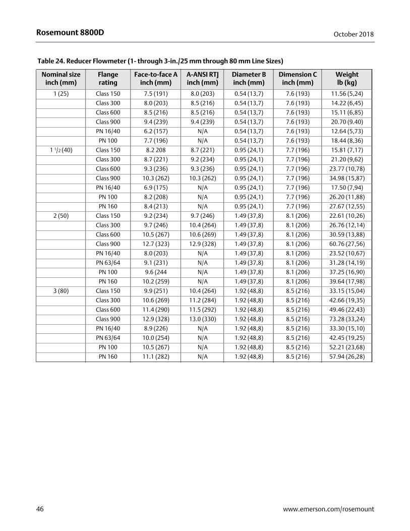
Rosemount 8800D October 2018
Table 24. Reducer Flowmeter (1- through 3-in./25 mm through 80 mm Line Sizes)
Nominal size inch (mm)
Flange rating
Face-to-face A inch (mm)
A-ANSI RTJ inch (mm)
Diameter B inch (mm)
Dimension C inch (mm)
Weightlb (kg)
1 (25) Class 150 7.5 (191) 8.0 (203) 0.54 (13,7) 7.6 (193) 11.56 (5,24)
Class 300 8.0 (203) 8.5 (216) 0.54 (13,7) 7.6 (193) 14.22 (6,45)
Class 600 8.5 (216) 8.5 (216) 0.54 (13,7) 7.6 (193) 15.11 (6,85)
Class 900 9.4 (239) 9.4 (239) 0.54 (13,7) 7.6 (193) 20.70 (9.40)
PN 16/40 6.2 (157) N/A 0.54 (13,7) 7.6 (193) 12.64 (5,73)
PN 100 7.7 (196) N/A 0.54 (13,7) 7.6 (193) 18.44 (8,36)
1 1/2 (40) Class 150 8.2 208 8.7 (221) 0.95 (24,1) 7.7 (196) 15.81 (7,17)
Class 300 8.7 (221) 9.2 (234) 0.95 (24,1) 7.7 (196) 21.20 (9,62)
Class 600 9.3 (236) 9.3 (236) 0.95 (24,1) 7.7 (196) 23.77 (10,78)
Class 900 10.3 (262) 10.3 (262) 0.95 (24,1) 7.7 (196) 34.98 (15,87)
PN 16/40 6.9 (175) N/A 0.95 (24,1) 7.7 (196) 17.50 (7,94)
PN 100 8.2 (208) N/A 0.95 (24,1) 7.7 (196) 26.20 (11,88)
PN 160 8.4 (213) N/A 0.95 (24,1) 7.7 (196) 27.67 (12,55)
2 (50) Class 150 9.2 (234) 9.7 (246) 1.49 (37,8) 8.1 (206) 22.61 (10,26)
Class 300 9.7 (246) 10.4 (264) 1.49 (37,8) 8.1 (206) 26.76 (12,14)
Class 600 10.5 (267) 10.6 (269) 1.49 (37,8) 8.1 (206) 30.59 (13,88)
Class 900 12.7 (323) 12.9 (328) 1.49 (37,8) 8.1 (206) 60.76 (27,56)
PN 16/40 8.0 (203) N/A 1.49 (37,8) 8.1 (206) 23.52 (10,67)
PN 63/64 9.1 (231) N/A 1.49 (37,8) 8.1 (206) 31.28 (14,19)
PN 100 9.6 (244 N/A 1.49 (37,8) 8.1 (206) 37.25 (16,90)
PN 160 10.2 (259) N/A 1.49 (37,8) 8.1 (206) 39.64 (17,98)
3 (80) Class 150 9.9 (251) 10.4 (264) 1.92 (48,8) 8.5 (216) 33.15 (15,04)
Class 300 10.6 (269) 11.2 (284) 1.92 (48,8) 8.5 (216) 42.66 (19,35)
Class 600 11.4 (290) 11.5 (292) 1.92 (48,8) 8.5 (216) 49.46 (22,43)
Class 900 12.9 (328) 13.0 (330) 1.92 (48,8) 8.5 (216) 73.28 (33,24)
PN 16/40 8.9 (226) N/A 1.92 (48,8) 8.5 (216) 33.30 (15,10)
PN 63/64 10.0 (254) N/A 1.92 (48,8) 8.5 (216) 42.45 (19,25)
PN 100 10.5 (267) N/A 1.92 (48,8) 8.5 (216) 52.21 (23,68)
PN 160 11.1 (282) N/A 1.92 (48,8) 8.5 (216) 57.94 (26,28)
46 www.emerson.com/rosemount
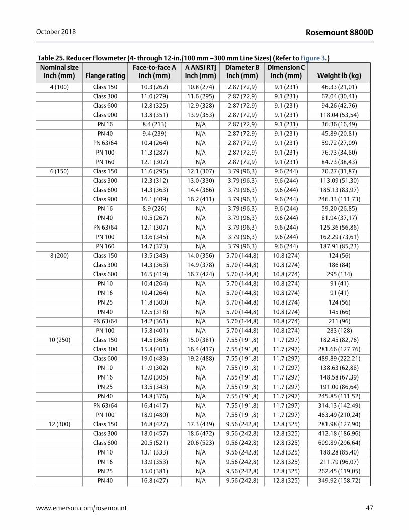
Rosemount 8800DOctober 2018
Table 25. Reducer Flowmeter (4- through 12-in./100 mm –300 mm Line Sizes) (Refer to Figure 3.)Nominal size
inch (mm) Flange ratingFace-to-face A
inch (mm)A ANSI RTJ inch (mm)
Diameter B inch (mm)
Dimension C inch (mm) Weight lb (kg)
4 (100) Class 150 10.3 (262) 10.8 (274) 2.87 (72,9) 9.1 (231) 46.33 (21,01)
Class 300 11.0 (279) 11.6 (295) 2.87 (72,9) 9.1 (231) 67.04 (30,41)
Class 600 12.8 (325) 12.9 (328) 2.87 (72,9) 9.1 (231) 94.26 (42,76)
Class 900 13.8 (351) 13.9 (353) 2.87 (72,9) 9.1 (231) 118.04 (53,54)
PN 16 8.4 (213) N/A 2.87 (72,9) 9.1 (231) 36.36 (16,49)
PN 40 9.4 (239) N/A 2.87 (72,9) 9.1 (231) 45.89 (20,81)
PN 63/64 10.4 (264) N/A 2.87 (72,9) 9.1 (231) 59.72 (27,09)
PN 100 11.3 (287) N/A 2.87 (72,9) 9.1 (231) 76.73 (34,80)
PN 160 12.1 (307) N/A 2.87 (72,9) 9.1 (231) 84.73 (38,43)
6 (150) Class 150 11.6 (295) 12.1 (307) 3.79 (96,3) 9.6 (244) 70.27 (31,87)
Class 300 12.3 (312) 13.0 (330) 3.79 (96,3) 9.6 (244) 113.09 (51,30)
Class 600 14.3 (363) 14.4 (366) 3.79 (96,3) 9.6 (244) 185.13 (83,97)
Class 900 16.1 (409) 16.2 (411) 3.79 (96,3) 9.6 (244) 246.33 (111,73)
PN 16 8.9 (226) N/A 3.79 (96,3) 9.6 (244) 59.20 (26,85)
PN 40 10.5 (267) N/A 3.79 (96,3) 9.6 (244) 81.94 (37,17)
PN 63/64 12.1 (307) N/A 3.79 (96,3) 9.6 (244) 125.36 (56,86)
PN 100 13.6 (345) N/A 3.79 (96,3) 9.6 (244) 162.29 (73,61)
PN 160 14.7 (373) N/A 3.79 (96,3) 9.6 (244) 187.91 (85,23)
8 (200) Class 150 13.5 (343) 14.0 (356) 5.70 (144,8) 10.8 (274) 124 (56)
Class 300 14.3 (363) 14.9 (378) 5.70 (144,8) 10.8 (274) 186 (84)
Class 600 16.5 (419) 16.7 (424) 5.70 (144,8) 10.8 (274) 295 (134)
PN 10 10.4 (264) N/A 5.70 (144,8) 10.8 (274) 91 (41)
PN 16 10.4 (264) N/A 5.70 (144,8) 10.8 (274) 91 (41)
PN 25 11.8 (300) N/A 5.70 (144,8) 10.8 (274) 124 (56)
PN 40 12.5 (318) N/A 5.70 (144,8) 10.8 (274) 145 (66)
PN 63/64 14.2 (361) N/A 5.70 (144,8) 10.8 (274) 211 (96)
PN 100 15.8 (401) N/A 5.70 (144,8) 10.8 (274) 283 (128)
10 (250) Class 150 14.5 (368) 15.0 (381) 7.55 (191,8) 11.7 (297) 182.45 (82,76)
Class 300 15.8 (401) 16.4 (417) 7.55 (191,8) 11.7 (297) 281.66 (127,76)
Class 600 19.0 (483) 19.2 (488) 7.55 (191,8) 11.7 (297) 489.89 (222,21)
PN 10 11.9 (302) N/A 7.55 (191,8) 11.7 (297) 138.63 (62,88)
PN 16 12.0 (305) N/A 7.55 (191,8) 11.7 (297) 148.58 (67,39)
PN 25 13.5 (343) N/A 7.55 (191,8) 11.7 (297) 191.00 (86,64)
PN 40 14.8 (376) N/A 7.55 (191,8) 11.7 (297) 245.85 (111,52)
PN 63/64 16.4 (417) N/A 7.55 (191,8) 11.7 (297) 314.13 (142,49)
PN 100 18.9 (480) N/A 7.55 (191,8) 11.7 (297) 463.49 (210,24)
12 (300) Class 150 16.8 (427) 17.3 (439) 9.56 (242,8) 12.8 (325) 281.98 (127,90)
Class 300 18.0 (457) 18.6 (472) 9.56 (242,8) 12.8 (325) 412.18 (186,96)
Class 600 20.5 (521) 20.6 (523) 9.56 (242,8) 12.8 (325) 609.89 (296,64)
PN 10 13.1 (333) N/A 9.56 (242,8) 12.8 (325) 188.28 (85,40)
PN 16 13.9 (353) N/A 9.56 (242,8) 12.8 (325) 211.79 (96,07)
PN 25 15.0 (381) N/A 9.56 (242,8) 12.8 (325) 262.45 (119,05)
PN 40 16.8 (427) N/A 9.56 (242,8) 12.8 (325) 349.92 (158,72)
47www.emerson.com/rosemount
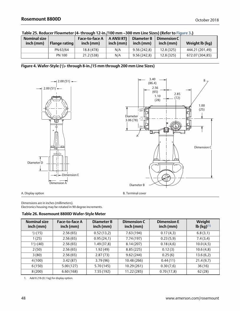
Rosemount 8800D October 2018
Figure 4. Wafer-Style (1/2- through 8-in./15 mm through 200 mm Line Sizes)
A. Display option B. Terminal cover
Dimensions are in inches (millimeters).Electronics housing may be rotated in 90 degree increments.
PN 63/64 18.8 (478) N/A 9.56 (242,8) 12.8 (325) 444.21 (201,49)
PN 100 21.2 (538) N/A 9.56 (242,8) 12.8 (325) 672.07 (304,85)
Table 25. Reducer Flowmeter (4- through 12-in./100 mm –300 mm Line Sizes) (Refer to Figure 3.)Nominal size
inch (mm) Flange ratingFace-to-face A
inch (mm)A ANSI RTJ inch (mm)
Diameter B inch (mm)
Dimension C inch (mm) Weight lb (kg)
2.00 (51)
2.00 (51)
Dimension E
Dimension A
Diameter D
B
Diameter B
A
1.00 (25)
3.40 (86.4)
2.85 (72)
2.56 (65)
1.10 (28)
Dimension C
Diameter3.06 (78)
Table 26. Rosemount 8800D Wafer-Style Meter
Nominal sizeinch (mm)
Face-to-face Ainch (mm)
Diameter Binch (mm)
Dimension Cinch (mm)
Dimension Einch (mm)
Weightlb (kg)(1)
1. Add 0.2 lb (0,1 kg) for display option.
1/2 (15) 2.56 (65) 0.52 (13,2) 7.63 (194) 0.17 (4,3) 6.8 (3,1)
1 (25) 2.56 (65) 0.95 (24,1) 7.74 (197) 0.23 (5,9) 7.4 (3,4)
11/2 (40) 2.56 (65) 1.49 (37,8) 8.14 (207) 0.18 (4,6) 10.0 (4,5)
2 (50) 2.56 (65) 1.92 (49) 8.85 (225) 0.12 (3) 10.6 (4,8)
3 (80) 2.56 (65) 2.87 (73) 9.62 (244) 0.25 (6) 13.6 (6,2)
4 (100) 3.42 (87) 3.79 (96) 10.48 (266) 0.44 (11) 21.4 (9,7)
6 (150) 5.00 (127) 5.70 (145) 10.29 (261) 0.30 (7,6) 36 (16)
8 (200) 6.60 (168) 7.55 (192) 11.22 (285) 0.70 (17,8) 62 (28)
48 www.emerson.com/rosemount
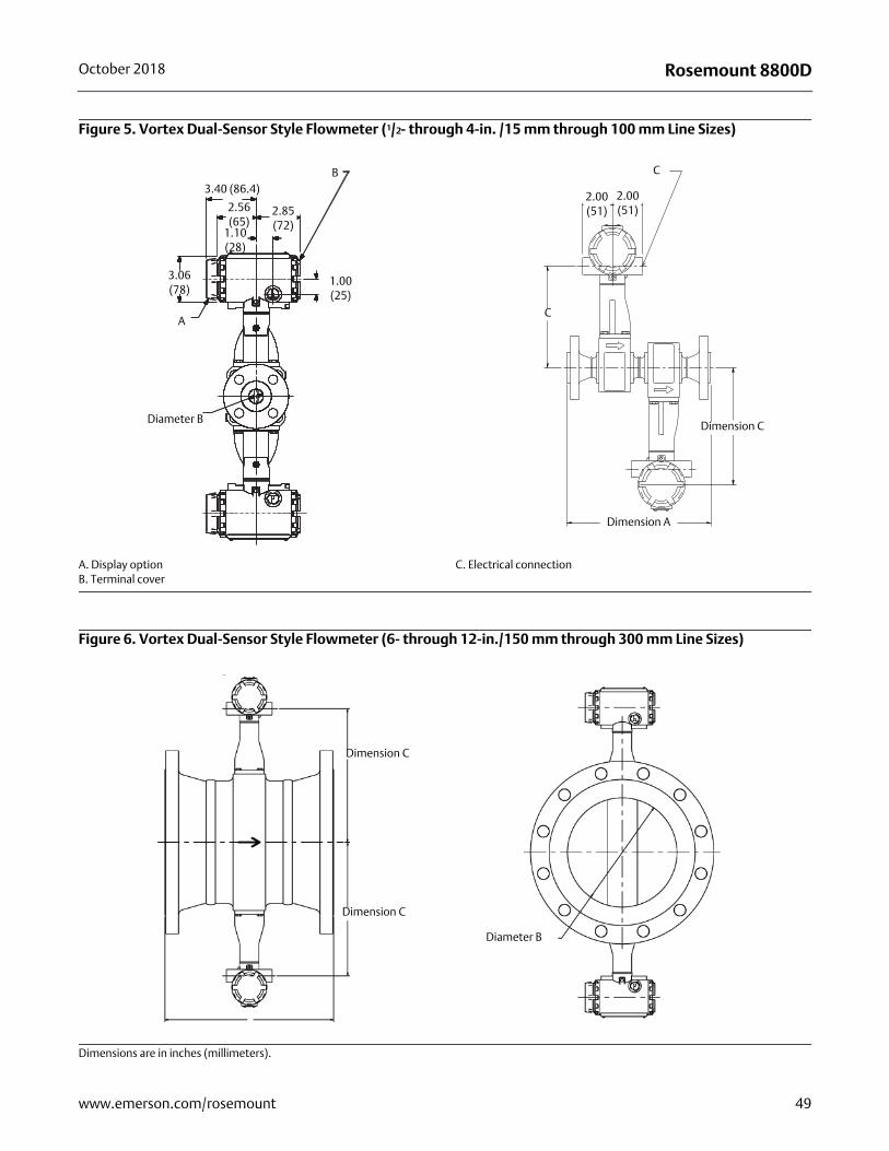
Rosemount 8800DOctober 2018
Figure 5. Vortex Dual-Sensor Style Flowmeter (1/2- through 4-in. /15 mm through 100 mm Line Sizes)
A. Display optionB. Terminal cover
C. Electrical connection
Figure 6. Vortex Dual-Sensor Style Flowmeter (6- through 12-in./150 mm through 300 mm Line Sizes)
Dimensions are in inches (millimeters).
3.40 (86.4)
2.56 (65)
1.10 (28)
3.06 (78)
2.85 (72)
Diameter B
1.00 (25)
A
B
2.00 (51)
2.00 (51)
Dimension C
C
C
Dimension A
Dimension C
Dimension C
Diameter B
49www.emerson.com/rosemount
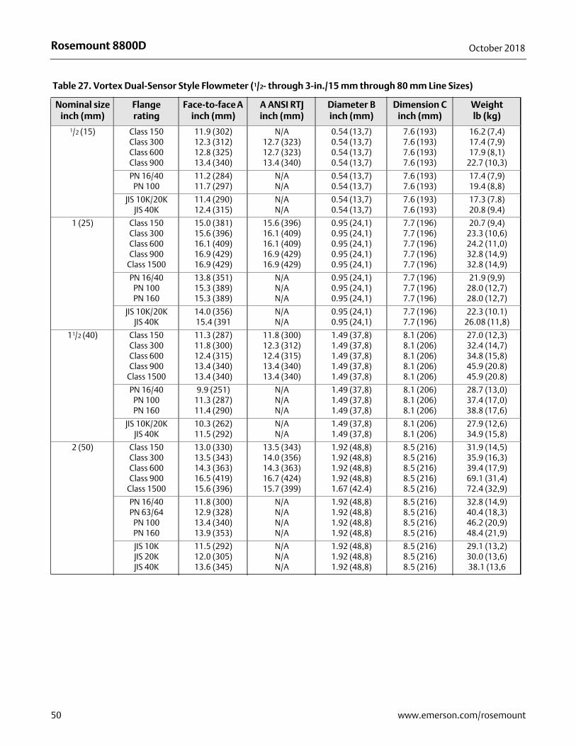
Rosemount 8800D October 2018
Table 27. Vortex Dual-Sensor Style Flowmeter (1/2- through 3-in./15 mm through 80 mm Line Sizes)
Nominal sizeinch (mm)
Flangerating
Face-to-face A inch (mm)
A ANSI RTJinch (mm)
Diameter B inch (mm)
Dimension C inch (mm)
Weightlb (kg)
1/2 (15) Class 150Class 300Class 600Class 900
11.9 (302)12.3 (312)12.8 (325)13.4 (340)
N/A12.7 (323)12.7 (323)13.4 (340)
0.54 (13,7)0.54 (13,7)0.54 (13,7)0.54 (13,7)
7.6 (193)7.6 (193)7.6 (193)7.6 (193)
16.2 (7,4)17.4 (7,9)17.9 (8,1)
22.7 (10,3)
PN 16/40PN 100
11.2 (284)11.7 (297)
N/AN/A
0.54 (13,7)0.54 (13,7)
7.6 (193)7.6 (193)
17.4 (7,9)19.4 (8,8)
JIS 10K/20KJIS 40K
11.4 (290)12.4 (315)
N/AN/A
0.54 (13,7)0.54 (13,7)
7.6 (193)7.6 (193)
17.3 (7.8)20.8 (9.4)
1 (25) Class 150Class 300Class 600Class 900
Class 1500
15.0 (381)15.6 (396)16.1 (409)16.9 (429)16.9 (429)
15.6 (396)16.1 (409)16.1 (409)16.9 (429)16.9 (429)
0.95 (24,1)0.95 (24,1)0.95 (24,1)0.95 (24,1)0.95 (24,1)
7.7 (196)7.7 (196)7.7 (196)7.7 (196)7.7 (196)
20.7 (9,4)23.3 (10,6)24.2 (11,0)32.8 (14,9)32.8 (14,9)
PN 16/40PN 100PN 160
13.8 (351)15.3 (389)15.3 (389)
N/AN/AN/A
0.95 (24,1)0.95 (24,1)0.95 (24,1)
7.7 (196)7.7 (196)7.7 (196)
21.9 (9,9)28.0 (12,7)28.0 (12,7)
JIS 10K/20KJIS 40K
14.0 (356)15.4 (391
N/AN/A
0.95 (24,1)0.95 (24,1)
7.7 (196)7.7 (196)
22.3 (10.1)26.08 (11,8)
11/2 (40) Class 150Class 300Class 600Class 900
Class 1500
11.3 (287)11.8 (300)12.4 (315)13.4 (340)13.4 (340)
11.8 (300)12.3 (312)12.4 (315)13.4 (340)13.4 (340)
1.49 (37,8)1.49 (37,8)1.49 (37,8)1.49 (37,8)1.49 (37,8)
8.1 (206)8.1 (206)8.1 (206)8.1 (206)8.1 (206)
27.0 (12,3)32.4 (14,7)34.8 (15,8)45.9 (20.8)45.9 (20.8)
PN 16/40PN 100PN 160
9.9 (251)11.3 (287)11.4 (290)
N/AN/AN/A
1.49 (37,8)1.49 (37,8)1.49 (37,8)
8.1 (206)8.1 (206)8.1 (206)
28.7 (13,0)37.4 (17,0)38.8 (17,6)
JIS 10K/20KJIS 40K
10.3 (262)11.5 (292)
N/AN/A
1.49 (37,8)1.49 (37,8)
8.1 (206)8.1 (206)
27.9 (12,6)34.9 (15,8)
2 (50) Class 150Class 300Class 600Class 900
Class 1500
13.0 (330)13.5 (343)14.3 (363)16.5 (419)15.6 (396)
13.5 (343)14.0 (356)14.3 (363)16.7 (424)15.7 (399)
1.92 (48,8)1.92 (48,8)1.92 (48,8)1.92 (48,8)1.67 (42.4)
8.5 (216)8.5 (216)8.5 (216)8.5 (216)8.5 (216)
31.9 (14,5)35.9 (16,3)39.4 (17,9)69.1 (31,4)72.4 (32,9)
PN 16/40PN 63/64
PN 100PN 160
11.8 (300)12.9 (328)13.4 (340)13.9 (353)
N/AN/AN/AN/A
1.92 (48,8)1.92 (48,8)1.92 (48,8)1.92 (48,8)
8.5 (216)8.5 (216)8.5 (216)8.5 (216)
32.8 (14,9)40.4 (18,3)46.2 (20,9)48.4 (21,9)
JIS 10KJIS 20KJIS 40K
11.5 (292)12.0 (305)13.6 (345)
N/AN/AN/A
1.92 (48,8)1.92 (48,8)1.92 (48,8)
8.5 (216)8.5 (216)8.5 (216)
29.1 (13,2)30.0 (13,6)38.1 (13,6
50 www.emerson.com/rosemount
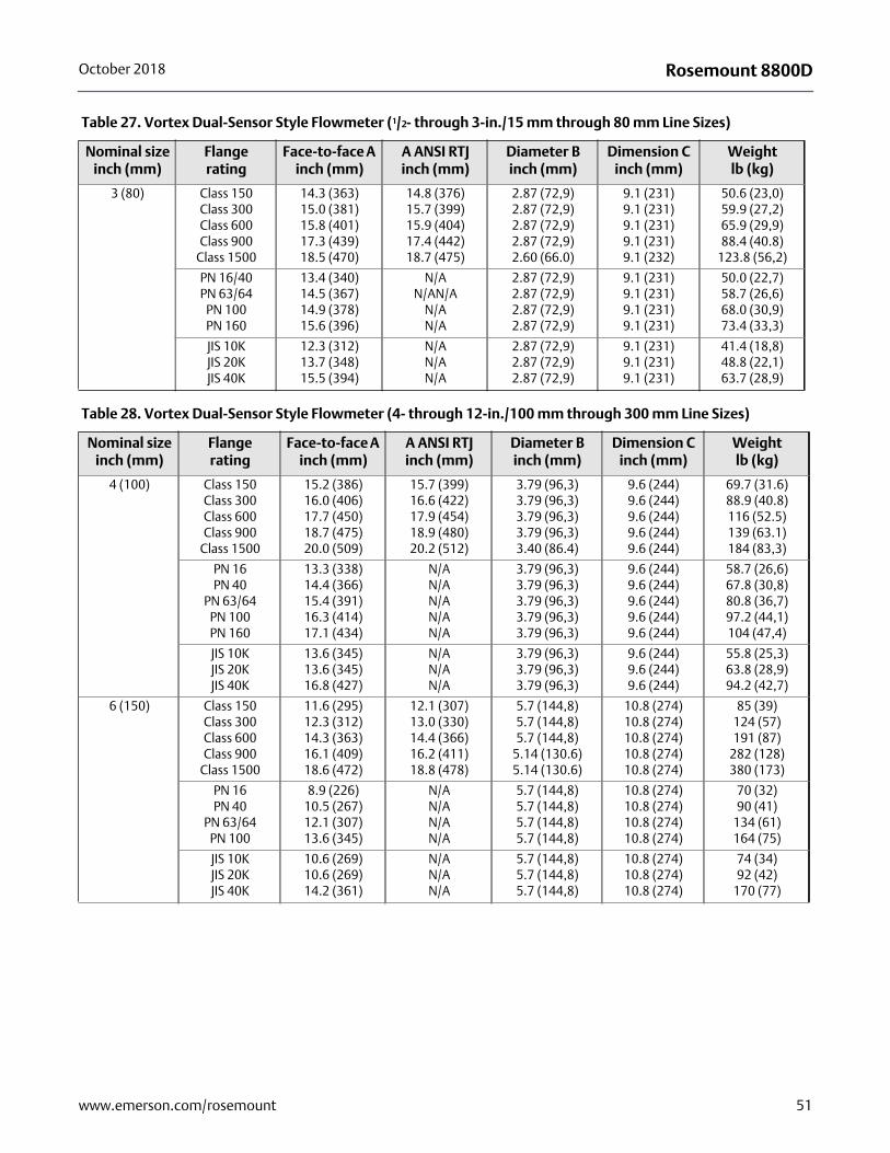
Rosemount 8800DOctober 2018
3 (80) Class 150Class 300Class 600Class 900
Class 1500
14.3 (363)15.0 (381)15.8 (401)17.3 (439)18.5 (470)
14.8 (376)15.7 (399)15.9 (404)17.4 (442)18.7 (475)
2.87 (72,9)2.87 (72,9)2.87 (72,9)2.87 (72,9)2.60 (66.0)
9.1 (231)9.1 (231)9.1 (231)9.1 (231)9.1 (232)
50.6 (23,0)59.9 (27,2)65.9 (29,9)88.4 (40.8)
123.8 (56,2)
PN 16/40PN 63/64
PN 100PN 160
13.4 (340)14.5 (367)14.9 (378)15.6 (396)
N/AN/AN/A
N/AN/A
2.87 (72,9)2.87 (72,9)2.87 (72,9)2.87 (72,9)
9.1 (231)9.1 (231)9.1 (231)9.1 (231)
50.0 (22,7)58.7 (26,6)68.0 (30,9)73.4 (33,3)
JIS 10KJIS 20KJIS 40K
12.3 (312)13.7 (348)15.5 (394)
N/AN/AN/A
2.87 (72,9)2.87 (72,9)2.87 (72,9)
9.1 (231)9.1 (231)9.1 (231)
41.4 (18,8)48.8 (22,1)63.7 (28,9)
Table 27. Vortex Dual-Sensor Style Flowmeter (1/2- through 3-in./15 mm through 80 mm Line Sizes)
Nominal sizeinch (mm)
Flangerating
Face-to-face A inch (mm)
A ANSI RTJinch (mm)
Diameter B inch (mm)
Dimension C inch (mm)
Weightlb (kg)
Table 28. Vortex Dual-Sensor Style Flowmeter (4- through 12-in./100 mm through 300 mm Line Sizes)
Nominal sizeinch (mm)
Flangerating
Face-to-face A inch (mm)
A ANSI RTJinch (mm)
Diameter B inch (mm)
Dimension C inch (mm)
Weightlb (kg)
4 (100) Class 150Class 300Class 600Class 900
Class 1500
15.2 (386)16.0 (406)17.7 (450)18.7 (475)20.0 (509)
15.7 (399)16.6 (422)17.9 (454)18.9 (480)20.2 (512)
3.79 (96,3)3.79 (96,3)3.79 (96,3)3.79 (96,3)3.40 (86.4)
9.6 (244)9.6 (244)9.6 (244)9.6 (244)9.6 (244)
69.7 (31.6)88.9 (40.8)116 (52.5)139 (63.1)184 (83,3)
PN 16PN 40
PN 63/64PN 100PN 160
13.3 (338)14.4 (366)15.4 (391)16.3 (414)17.1 (434)
N/AN/AN/AN/AN/A
3.79 (96,3)3.79 (96,3)3.79 (96,3)3.79 (96,3)3.79 (96,3)
9.6 (244)9.6 (244)9.6 (244)9.6 (244)9.6 (244)
58.7 (26,6)67.8 (30,8)80.8 (36,7)97.2 (44,1)104 (47,4)
JIS 10KJIS 20KJIS 40K
13.6 (345)13.6 (345)16.8 (427)
N/AN/AN/A
3.79 (96,3)3.79 (96,3)3.79 (96,3)
9.6 (244)9.6 (244)9.6 (244)
55.8 (25,3)63.8 (28,9)94.2 (42,7)
6 (150) Class 150Class 300Class 600Class 900
Class 1500
11.6 (295)12.3 (312)14.3 (363)16.1 (409)18.6 (472)
12.1 (307)13.0 (330)14.4 (366)16.2 (411)18.8 (478)
5.7 (144,8)5.7 (144,8)5.7 (144,8)
5.14 (130.6)5.14 (130.6)
10.8 (274)10.8 (274)10.8 (274)10.8 (274)10.8 (274)
85 (39)124 (57)191 (87)
282 (128)380 (173)
PN 16PN 40
PN 63/64PN 100
8.9 (226)10.5 (267)12.1 (307)13.6 (345)
N/AN/AN/AN/A
5.7 (144,8)5.7 (144,8)5.7 (144,8)5.7 (144,8)
10.8 (274)10.8 (274)10.8 (274)10.8 (274)
70 (32)90 (41)
134 (61)164 (75)
JIS 10KJIS 20KJIS 40K
10.6 (269)10.6 (269)14.2 (361)
N/AN/AN/A
5.7 (144,8)5.7 (144,8)5.7 (144,8)
10.8 (274)10.8 (274)10.8 (274)
74 (34)92 (42)
170 (77)
51www.emerson.com/rosemount
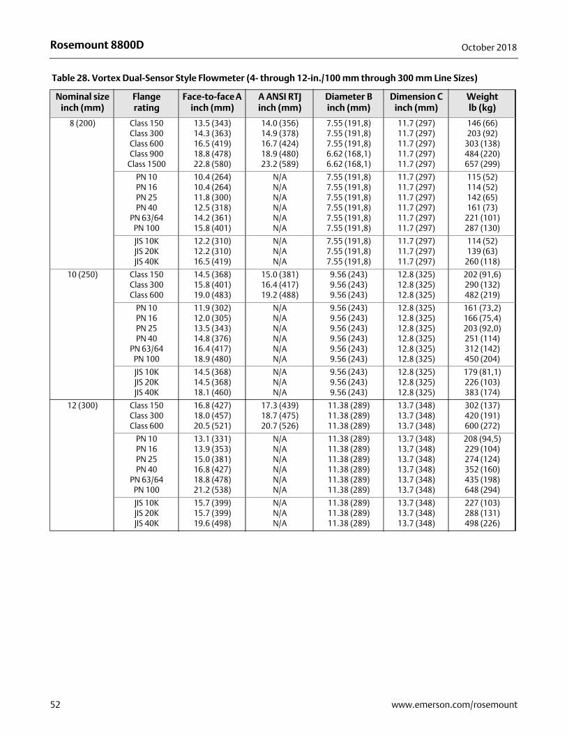
Rosemount 8800D October 2018
8 (200) Class 150Class 300Class 600Class 900
Class 1500
13.5 (343)14.3 (363)16.5 (419)18.8 (478)22.8 (580)
14.0 (356)14.9 (378)16.7 (424)18.9 (480)23.2 (589)
7.55 (191,8)7.55 (191,8)7.55 (191,8)6.62 (168,1)6.62 (168,1)
11.7 (297)11.7 (297)11.7 (297)11.7 (297)11.7 (297)
146 (66)203 (92)
303 (138)484 (220)657 (299)
PN 10PN 16PN 25PN 40
PN 63/64PN 100
10.4 (264)10.4 (264)11.8 (300)12.5 (318)14.2 (361)15.8 (401)
N/AN/AN/AN/AN/AN/A
7.55 (191,8)7.55 (191,8)7.55 (191,8)7.55 (191,8)7.55 (191,8)7.55 (191,8)
11.7 (297)11.7 (297)11.7 (297)11.7 (297)11.7 (297)11.7 (297)
115 (52)114 (52)142 (65)161 (73)
221 (101)287 (130)
JIS 10KJIS 20KJIS 40K
12.2 (310)12.2 (310)16.5 (419)
N/AN/AN/A
7.55 (191,8)7.55 (191,8)7.55 (191,8)
11.7 (297)11.7 (297)11.7 (297)
114 (52)139 (63)
260 (118)
10 (250) Class 150Class 300Class 600
14.5 (368)15.8 (401)19.0 (483)
15.0 (381)16.4 (417)19.2 (488)
9.56 (243)9.56 (243)9.56 (243)
12.8 (325)12.8 (325)12.8 (325)
202 (91,6)290 (132)482 (219)
PN 10PN 16PN 25PN 40
PN 63/64PN 100
11.9 (302)12.0 (305)13.5 (343)14.8 (376)16.4 (417)18.9 (480)
N/AN/AN/AN/AN/AN/A
9.56 (243)9.56 (243)9.56 (243)9.56 (243)9.56 (243)9.56 (243)
12.8 (325)12.8 (325)12.8 (325)12.8 (325)12.8 (325)12.8 (325)
161 (73,2)166 (75,4)203 (92,0)251 (114)312 (142)450 (204)
JIS 10KJIS 20KJIS 40K
14.5 (368)14.5 (368)18.1 (460)
N/AN/AN/A
9.56 (243)9.56 (243)9.56 (243)
12.8 (325)12.8 (325)12.8 (325)
179 (81,1)226 (103)383 (174)
12 (300) Class 150Class 300Class 600
16.8 (427)18.0 (457)20.5 (521)
17.3 (439)18.7 (475)20.7 (526)
11.38 (289)11.38 (289)11.38 (289)
13.7 (348)13.7 (348)13.7 (348)
302 (137)420 (191)600 (272)
PN 10PN 16PN 25PN 40
PN 63/64PN 100
13.1 (331)13.9 (353)15.0 (381)16.8 (427)18.8 (478)21.2 (538)
N/AN/AN/AN/AN/AN/A
11.38 (289)11.38 (289)11.38 (289)11.38 (289)11.38 (289)11.38 (289)
13.7 (348)13.7 (348)13.7 (348)13.7 (348)13.7 (348)13.7 (348)
208 (94,5)229 (104)274 (124)352 (160)435 (198)648 (294)
JIS 10KJIS 20KJIS 40K
15.7 (399)15.7 (399)19.6 (498)
N/AN/AN/A
11.38 (289)11.38 (289)11.38 (289)
13.7 (348)13.7 (348)13.7 (348)
227 (103)288 (131)498 (226)
Table 28. Vortex Dual-Sensor Style Flowmeter (4- through 12-in./100 mm through 300 mm Line Sizes)
Nominal sizeinch (mm)
Flangerating
Face-to-face A inch (mm)
A ANSI RTJinch (mm)
Diameter B inch (mm)
Dimension C inch (mm)
Weightlb (kg)
52 www.emerson.com/rosemount
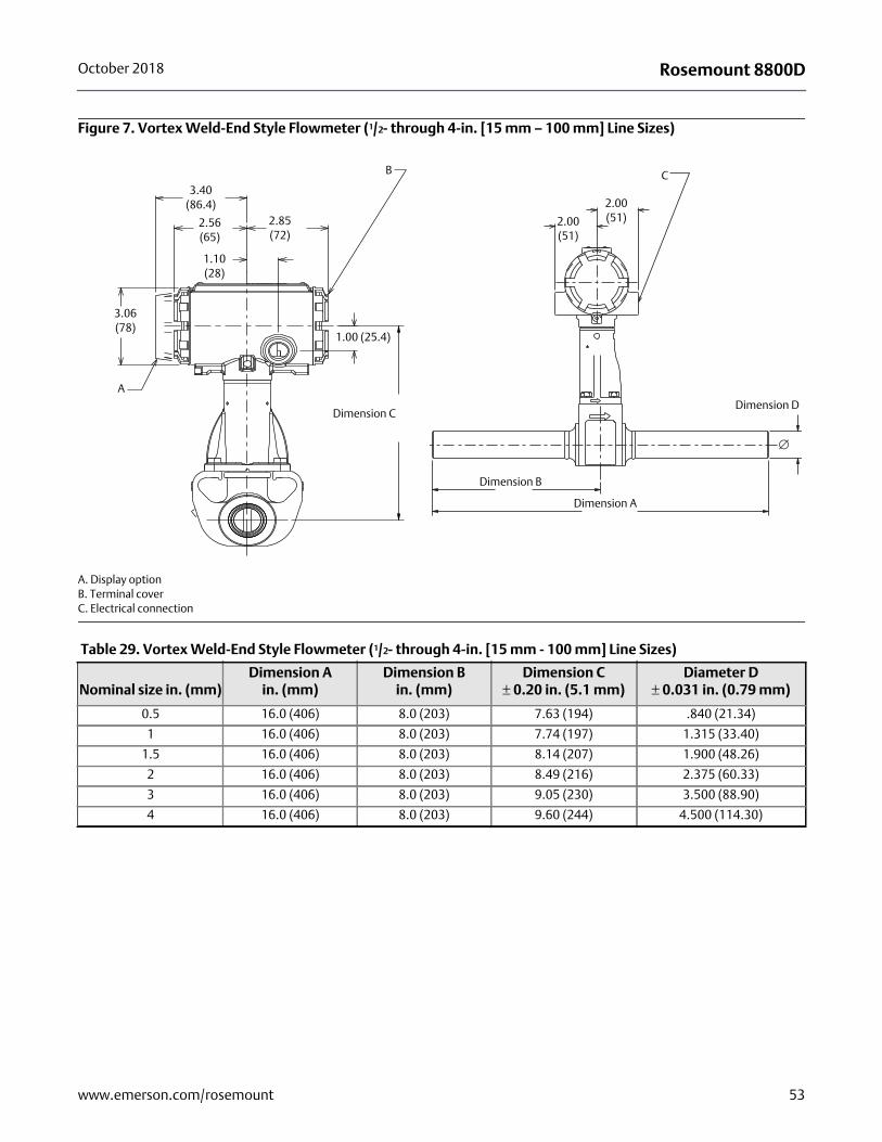
Rosemount 8800DOctober 2018
Figure 7. Vortex Weld-End Style Flowmeter (1/2- through 4-in. [15 mm – 100 mm] Line Sizes)
A. Display optionB. Terminal coverC. Electrical connection
A
3.06(78)
3.40(86.4)
2.56(65)
2.85(72)
B
Dimension C
1.00 (25.4)
1.10(28)
C
2.00 (51)
2.00 (51)
Dimension B
Dimension A
Dimension D
Table 29. Vortex Weld-End Style Flowmeter (1/2- through 4-in. [15 mm - 100 mm] Line Sizes)
Nominal size in. (mm)Dimension A
in. (mm)Dimension B
in. (mm)Dimension C
± 0.20 in. (5.1 mm)Diameter D
± 0.031 in. (0.79 mm)
0.5 16.0 (406) 8.0 (203) 7.63 (194) .840 (21.34)
1 16.0 (406) 8.0 (203) 7.74 (197) 1.315 (33.40)
1.5 16.0 (406) 8.0 (203) 8.14 (207) 1.900 (48.26)
2 16.0 (406) 8.0 (203) 8.49 (216) 2.375 (60.33)
3 16.0 (406) 8.0 (203) 9.05 (230) 3.500 (88.90)
4 16.0 (406) 8.0 (203) 9.60 (244) 4.500 (114.30)
53www.emerson.com/rosemount
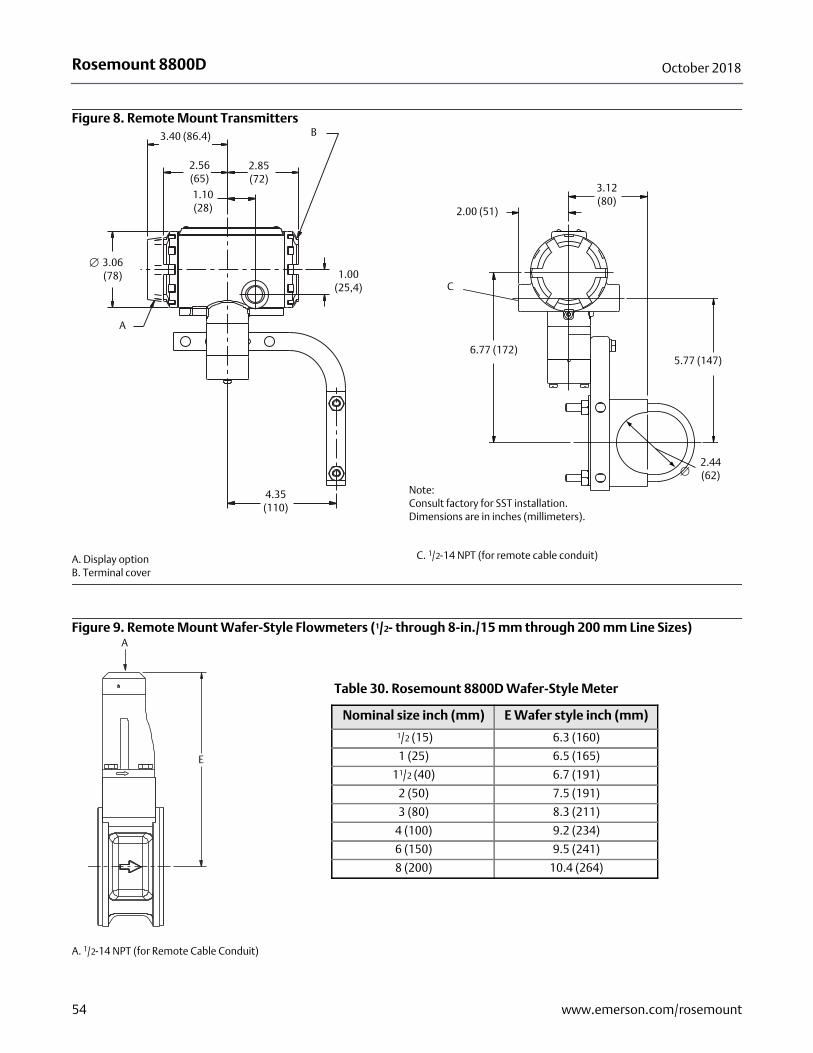
Rosemount 8800D October 2018
Figure 8. Remote Mount Transmitters
A. Display optionB. Terminal cover
C. 1/2-14 NPT (for remote cable conduit)
Figure 9. Remote Mount Wafer-Style Flowmeters (1/2- through 8-in./15 mm through 200 mm Line Sizes)
A. 1/2-14 NPT (for Remote Cable Conduit)
3.40 (86.4)
2.56 (65)
1.10 (28)
2.85 (72)
1.00 (25,4)
4.35 (110)
3.06 (78)
A
B
5.77 (147)
C
2.00 (51)
3.12 (80)
6.77 (172)
2.44 (62)
Note:Consult factory for SST installation. Dimensions are in inches (millimeters).
E
A
Table 30. Rosemount 8800D Wafer-Style Meter
Nominal size inch (mm) E Wafer style inch (mm)
1/2 (15) 6.3 (160)
1 (25) 6.5 (165)
11/2 (40) 6.7 (191)
2 (50) 7.5 (191)
3 (80) 8.3 (211)
4 (100) 9.2 (234)
6 (150) 9.5 (241)
8 (200) 10.4 (264)
54 www.emerson.com/rosemount
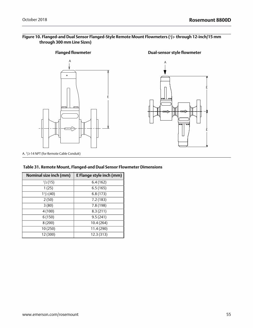
Rosemount 8800DOctober 2018
Figure 10. Flanged-and Dual Sensor Flanged-Style Remote Mount Flowmeters (1/2- through 12-inch/15 mm through 300 mm Line Sizes)
A. 1/2-14 NPT (for Remote Cable Conduit)
Flanged flowmeter Dual-sensor style flowmeter
A
E
A
E
E
Table 31. Remote Mount, Flanged-and Dual Sensor Flowmeter Dimensions
Nominal size inch (mm) E Flange style inch (mm)
1/2 (15) 6.4 (162)
1 (25) 6.5 (165)
11/2 (40) 6.8 (173)
2 (50) 7.2 (183)
3 (80) 7.8 (198)
4 (100) 8.3 (211)
6 (150) 9.5 (241)
8 (200) 10.4 (264)
10 (250) 11.4 (290)
12 (300) 12.3 (313)
55www.emerson.com/rosemount
Product Data SheetOctober 2018
Rosemount 8800D 00813-0100-4004, Rev KF
Emerson Automation Solutions USA 7070 Winchester CircleBoulder, Colorado USA 80301T +1 303-527-5200T +1 800-522-6277F +1 303-530-8459www.emerson.com
Emerson Automation Solutions Europe Neonstraat 16718 WX EdeThe NetherlandsT +31 (0) 70 413 6666F +31 (0) 318 495 556www.micromotion.nl
Emerson Automation Solutions Asia 1 Pandan CrescentSingapore 128461Republic of SingaporeT +65 6363-7766F +65 6770-8003
Emerson Automation Solutions United KingdomEmerson Process Management LimitedHorsfield WayBredbury Industrial EstateStockport SK6 2SU U.K.T +44 0870 240 1978F +44 0800 966 181
Emerson Automation Solutions Japan 1-2-5, Higashi ShinagawaShinagawa-kuTokyo 140-0002 JapanT +81 3 5769-6803F +81 3 5769-6844
©2018 Rosemount, Inc. All rights reserved.
The Emerson logo is a trademark and service mark of Emerson Electric Co. Rosemount, 8600, 8700,8800 marks are marks of one of the Emerson Automation Solutions family of companies. All othermarks are property of their respective owners.