Embed Size (px)
Citation preview
www.rosemount.com
¢00825-0100-4725.¤
Quick Installation Guide00825-0100-4727, Rev AAApril 2009 Rosemount 8700 Series
Start
Step 1: Pre-InstallationStep 2: HandlingStep 3: MountingStep 4: Installation
(Flanged Sensors)(Wafer Sensors)(Sanitary Sensors)
Step 5: GroundingStep 6: WiringStep 7: Basic Configuration
End
Rosemount 8700 Series Magnetic Flowmeter Sensors
4727_revAA_QIG.fm Page 1 Tuesday, April 28, 2009 2:14 PM
Quick Installation Guide00825-0100-4727, Rev AA
April 2009Rosemount 8700 Series
4727_revAA_QIG.fm Page 2 Tuesday, April 28, 2009 2:14 PM
© 2009 Rosemount Inc. All rights reserved. All marks property of owner.
IMPORTANT NOTICEThis document provides basic installation guidelines for the Rosemount® 8700 Series Sensors. It does not provide instructions for detailed configuration, diagnostics, maintenance, service, troubleshooting, explosion-proof, flame-proof, or intrinsically safe (I.S.) installations. Refer to the Rosemount 8700 reference manual (document number 00809-0100-4727) for more instructions. The manual and this QIG are also available electronically on www.rosemount.com.
WARNINGFailure to follow these installation guidelines could result in death or serious injury:Installation and servicing instructions are for use by qualified personnel only. Do not perform any servicing other than that contained in the operating instructions, unless qualified. Verify that the operating environment of the sensor and transmitter is consistent with the appropriate FM, CSA, ATEX, or IECEx approval.
WARNINGThe sensor liner is vulnerable to handling damage. Never place anything through the sensor for the purpose of lifting or gaining leverage. Liner damage can render the sensor useless.To avoid possible damage to the sensor liner ends, do not use metallic or spiral-wound gaskets. If frequent removal is anticipated, take precautions to protect the liner ends. Short spool pieces attached to the sensor ends are often used for protection.Correct flange bolt tightening is crucial for proper sensor operation and life. All bolts must be tightened in the proper sequence to the specified torque limits. Failure to observe these instructions could result in severe damage to the sensor lining and possible sensor replacement.
Emerson Process ManagementRosemount Inc.12001 Technology DriveEden Prairie, MN USA 55344T (US) (800) 999-9307T (Intnl) (952) 906-8888F (952) 949-7001
Emerson Process Management FlowNeonstraat 1 6718 WX EdeThe Netherlands T +31 (0)318 495555F +31(0) 318 495556
Emerson Process Management Asia Pacific Private Limited1 Pandan CrescentSingapore 128461T (65) 6777 8211F (65) 6777 0947/65 6777 0743
Emerson FZEP.O. Box 17033Jebel Ali Free ZoneDubai UAETel +971 4 811 8100Fax +971 4 886 5465
2
Quick Installation Guide00825-0100-4727, Rev AAApril 2009 Rosemount 8700 Series
4727_revAA_QIG.fm Page 3 Tuesday, April 28, 2009 2:14 PM
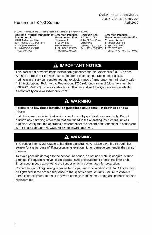
STEP 1: HANDLINGHandle all parts carefully to prevent damage. Whenever possible, transport the system to the installation site in the original shipping containers. PTFE-lined sensors are shipped with end covers that protect it from both mechanical damage and normal unrestrained distortion. Remove the end covers just before installation.
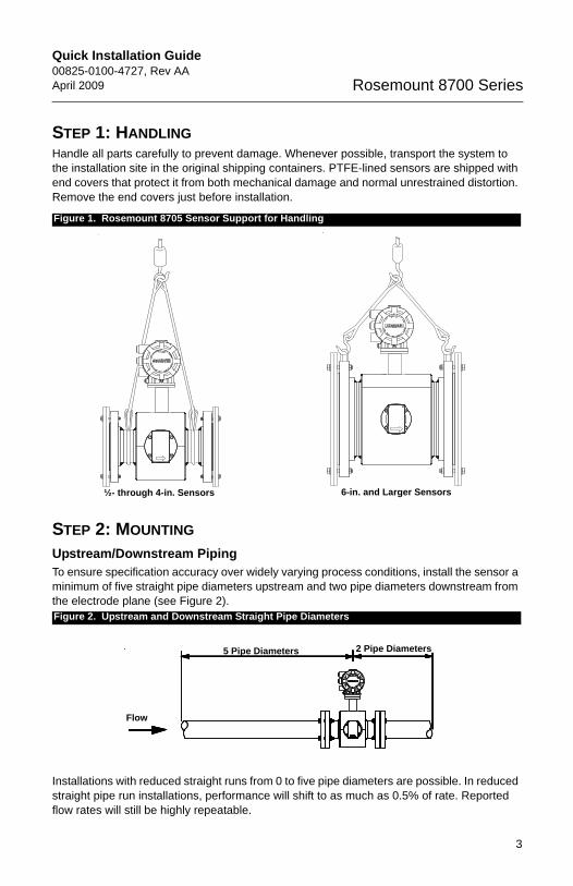
STEP 2: MOUNTINGUpstream/Downstream PipingTo ensure specification accuracy over widely varying process conditions, install the sensor a minimum of five straight pipe diameters upstream and two pipe diameters downstream from the electrode plane (see Figure 2).
Installations with reduced straight runs from 0 to five pipe diameters are possible. In reduced straight pipe run installations, performance will shift to as much as 0.5% of rate. Reported flow rates will still be highly repeatable.
Figure 1. Rosemount 8705 Sensor Support for Handling
Figure 2. Upstream and Downstream Straight Pipe Diameters
½- through 4-in. Sensors 6-in. and Larger Sensors
5 Pipe Diameters 2 Pipe Diameters
Flow
3
Quick Installation Guide00825-0100-4727, Rev AA
April 2009Rosemount 8700 Series
4727_revAA_QIG.fm Page 4 Tuesday, April 28, 2009 2:14 PM
4
Flow DirectionThe sensor should be mounted so the FORWARD end of the flow arrow, shown on the sensor identification tag, points in the direction of flow through the tube.
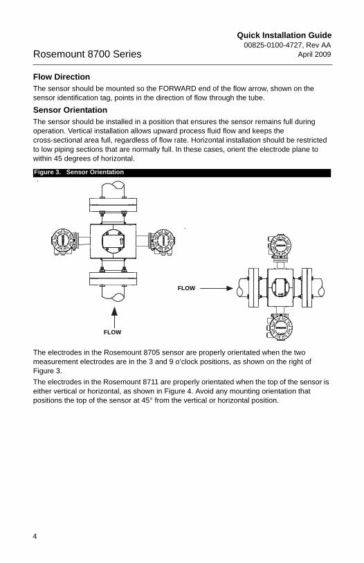
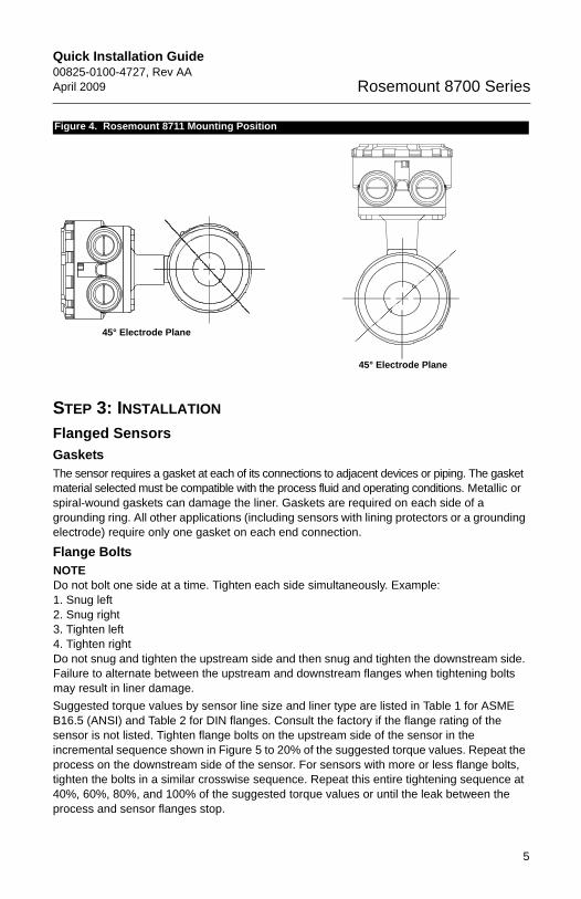
Sensor OrientationThe sensor should be installed in a position that ensures the sensor remains full during operation. Vertical installation allows upward process fluid flow and keeps the cross-sectional area full, regardless of flow rate. Horizontal installation should be restricted to low piping sections that are normally full. In these cases, orient the electrode plane to within 45 degrees of horizontal.
The electrodes in the Rosemount 8705 sensor are properly orientated when the two measurement electrodes are in the 3 and 9 o’clock positions, as shown on the right of Figure 3.The electrodes in the Rosemount 8711 are properly orientated when the top of the sensor is either vertical or horizontal, as shown in Figure 4. Avoid any mounting orientation that positions the top of the sensor at 45° from the vertical or horizontal position.
Figure 3. Sensor Orientation
FLOW
FLOW
Quick Installation Guide00825-0100-4727, Rev AAApril 2009 Rosemount 8700 Series
4727_revAA_QIG.fm Page 5 Tuesday, April 28, 2009 2:14 PM
STEP 3: INSTALLATIONFlanged SensorsGasketsThe sensor requires a gasket at each of its connections to adjacent devices or piping. The gasket material selected must be compatible with the process fluid and operating conditions. Metallic or spiral-wound gaskets can damage the liner. Gaskets are required on each side of a grounding ring. All other applications (including sensors with lining protectors or a grounding electrode) require only one gasket on each end connection.
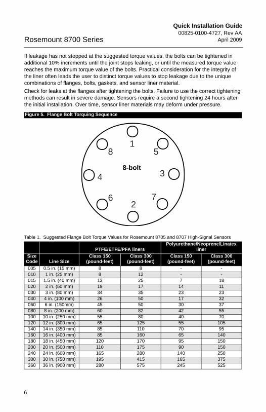
Flange BoltsNOTEDo not bolt one side at a time. Tighten each side simultaneously. Example: 1. Snug left2. Snug right3. Tighten left4. Tighten rightDo not snug and tighten the upstream side and then snug and tighten the downstream side. Failure to alternate between the upstream and downstream flanges when tightening bolts may result in liner damage.Suggested torque values by sensor line size and liner type are listed in Table 1 for ASME B16.5 (ANSI) and Table 2 for DIN flanges. Consult the factory if the flange rating of the sensor is not listed. Tighten flange bolts on the upstream side of the sensor in the incremental sequence shown in Figure 5 to 20% of the suggested torque values. Repeat the process on the downstream side of the sensor. For sensors with more or less flange bolts, tighten the bolts in a similar crosswise sequence. Repeat this entire tightening sequence at 40%, 60%, 80%, and 100% of the suggested torque values or until the leak between the process and sensor flanges stop.
Figure 4. Rosemount 8711 Mounting Position
45° Electrode Plane
45° Electrode Plane
5
Quick Installation Guide00825-0100-4727, Rev AA
April 2009Rosemount 8700 Series
4727_revAA_QIG.fm Page 6 Tuesday, April 28, 2009 2:14 PM
If leakage has not stopped at the suggested torque values, the bolts can be tightened in additional 10% increments until the joint stops leaking, or until the measured torque value reaches the maximum torque value of the bolts. Practical consideration for the integrity of the liner often leads the user to distinct torque values to stop leakage due to the unique combinations of flanges, bolts, gaskets, and sensor liner material.Check for leaks at the flanges after tightening the bolts. Failure to use the correct tightening methods can result in severe damage. Sensors require a second tightening 24 hours after the initial installation. Over time, sensor liner materials may deform under pressure.
Figure 5. Flange Bolt Torquing Sequence
Table 1. Suggested Flange Bolt Torque Values for Rosemount 8705 and 8707 High-Signal Sensors
PTFE/ETFE/PFA linersPolyurethane/Neoprene/Linatex
linerSize Code Line Size
Class 150(pound-feet)
Class 300(pound-feet)
Class 150(pound-feet)
Class 300(pound-feet)
005 0.5 in. (15 mm) 8 8 - -010 1 in. (25 mm) 8 12 - -015 1.5 in. (40 mm) 13 25 7 18020 2 in. (50 mm) 19 17 14 11030 3 in. (80 mm) 34 35 23 23040 4 in. (100 mm) 26 50 17 32060 6 in. (150mm) 45 50 30 37080 8 in. (200 mm) 60 82 42 55100 10 in. (250 mm) 55 80 40 70120 12 in. (300 mm) 65 125 55 105140 14 in. (350 mm) 85 110 70 95160 16 in. (400 mm) 85 160 65 140180 18 in. (450 mm) 120 170 95 150200 20 in. (500 mm) 110 175 90 150240 24 in. (600 mm) 165 280 140 250300 30 in. (750 mm) 195 415 165 375360 36 in. (900 mm) 280 575 245 525
15
3
7
8
4
62
8-bolt
6
Quick Installation Guide00825-0100-4727, Rev AAApril 2009 Rosemount 8700 Series
4727_revAA_QIG.fm Page 7 Tuesday, April 28, 2009 2:14 PM
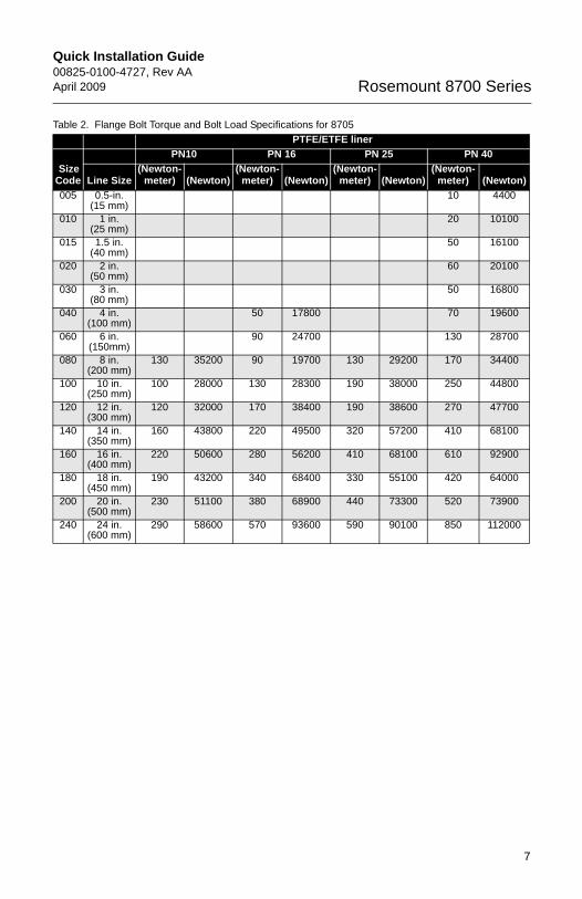
Table 2. Flange Bolt Torque and Bolt Load Specifications for 8705PTFE/ETFE liner
Size Code
PN10 PN 16 PN 25 PN 40
Line Size(Newton-
meter) (Newton)(Newton-
meter) (Newton)(Newton-
meter) (Newton)(Newton-
meter) (Newton)005 0.5-in.
(15 mm)10 4400
010 1 in.(25 mm)
20 10100
015 1.5 in. (40 mm)
50 16100
020 2 in.(50 mm)
60 20100
030 3 in. (80 mm)
50 16800
040 4 in. (100 mm)
50 17800 70 19600
060 6 in. (150mm)
90 24700 130 28700
080 8 in.(200 mm)
130 35200 90 19700 130 29200 170 34400
100 10 in. (250 mm)
100 28000 130 28300 190 38000 250 44800
120 12 in. (300 mm)
120 32000 170 38400 190 38600 270 47700
140 14 in. (350 mm)
160 43800 220 49500 320 57200 410 68100
160 16 in. (400 mm)
220 50600 280 56200 410 68100 610 92900
180 18 in. (450 mm)
190 43200 340 68400 330 55100 420 64000
200 20 in. (500 mm)
230 51100 380 68900 440 73300 520 73900
240 24 in. (600 mm)
290 58600 570 93600 590 90100 850 112000
7
Quick Installation Guide00825-0100-4727, Rev AA
April 2009Rosemount 8700 Series
4727_revAA_QIG.fm Page 8 Tuesday, April 28, 2009 2:14 PM
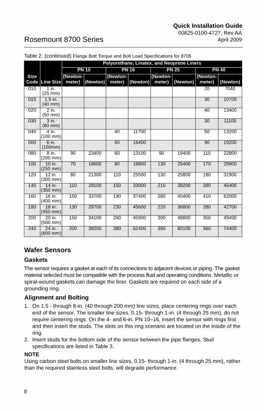
Table 2. (continued) Flange Bolt Torque and Bolt Load Specifications for 8705
Wafer SensorsGasketsThe sensor requires a gasket at each of its connections to adjacent devices or piping. The gasket material selected must be compatible with the process fluid and operating conditions. Metallic or spiral-wound gaskets can damage the liner. Gaskets are required on each side of a grounding ring.
Alignment and Bolting1. On 1.5 - through 8-in. (40 through 200 mm) line sizes, place centering rings over each
end of the sensor. The smaller line sizes, 0.15- through 1-in. (4 through 25 mm), do not require centering rings. On the 4- and 6-in. PN 10–16, insert the sensor with rings first and then insert the studs. The slots on this ring scenario are located on the inside of the ring.
2. Insert studs for the bottom side of the sensor between the pipe flanges. Stud specifications are listed in Table 3.
NOTEUsing carbon steel bolts on smaller line sizes, 0.15- through 1-in. (4 through 25 mm), rather than the required stainless steel bolts, will degrade performance.
Size Code Line Size
Polyurethane, Linatex, and Neoprene LinersPN 10 PN 16 PN 25 PN 40
(Newton-meter) (Newton)
(Newton-meter) (Newton)
(Newton-meter) (Newton)
(Newton-meter) (Newton)
010 1 in. (25 mm)
20 7040
015 1.5 in. (40 mm)
30 10700
020 2 in.(50 mm)
40 13400
030 3 in.(80 mm)
30 11100
040 4 in. (100 mm)
40 11700 50 13200
060 6 in. (150mm)
60 16400 90 19200
080 8 in. (200 mm)
90 23400 60 13100 90 19400 110 22800
100 10 in. (250 mm)
70 18600 80 18800 130 25400 170 29900
120 12 in. (300 mm)
80 21300 110 25500 130 25800 180 31900
140 14 in. (350 mm)
110 29100 150 33000 210 38200 280 45400
160 16 in. (400 mm)
150 33700 190 37400 280 45400 410 62000
180 18 in. (450 mm)
130 28700 230 45600 220 36800 280 42700
200 20 in. (500 mm)
150 34100 260 45900 300 48800 350 49400
240 24 in. (600 mm)
200 39200 380 62400 390 60100 560 74400
8
Quick Installation Guide00825-0100-4727, Rev AAApril 2009 Rosemount 8700 Series
4727_revAA_QIG.fm Page 9 Tuesday, April 28, 2009 2:14 PM
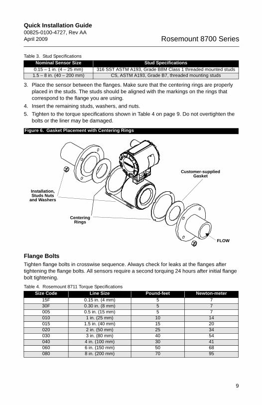
3. Place the sensor between the flanges. Make sure that the centering rings are properly placed in the studs. The studs should be aligned with the markings on the rings that correspond to the flange you are using.
4. Insert the remaining studs, washers, and nuts.5. Tighten to the torque specifications shown in Table 4 on page 9. Do not overtighten the
bolts or the liner may be damaged.
Flange BoltsTighten flange bolts in crosswise sequence. Always check for leaks at the flanges after tightening the flange bolts. All sensors require a second torquing 24 hours after initial flange bolt tightening.
Table 3. Stud SpecificationsNominal Sensor Size Stud Specifications
0.15 – 1 in. (4 – 25 mm) 316 SST ASTM A193, Grade B8M Class 1 threaded mounted studs1.5 – 8 in. (40 – 200 mm) CS, ASTM A193, Grade B7, threaded mounting studs
Figure 6. Gasket Placement with Centering Rings
Table 4. Rosemount 8711 Torque SpecificationsSize Code Line Size Pound-feet Newton-meter
15F 0.15 in. (4 mm) 5 730F 0.30 in. (8 mm) 5 7005 0.5 in. (15 mm) 5 7010 1 in. (25 mm) 10 14015 1.5 in. (40 mm) 15 20020 2 in. (50 mm) 25 34030 3 in. (80 mm) 40 54040 4 in. (100 mm) 30 41060 6 in. (150 mm) 50 68080 8 in. (200 mm) 70 95
Centering Rings
Installation, Studs Nuts
and Washers
Customer-supplied Gasket
FLOW
9
Quick Installation Guide00825-0100-4727, Rev AA
April 2009Rosemount 8700 Series
4727_revAA_QIG.fm Page 10 Tuesday, April 28, 2009 2:14 PM
10
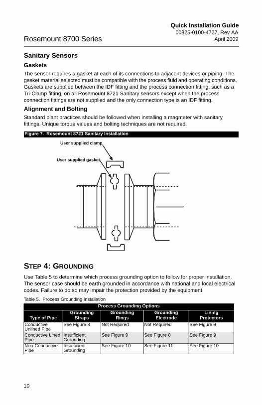
Sanitary SensorsGasketsThe sensor requires a gasket at each of its connections to adjacent devices or piping. The gasket material selected must be compatible with the process fluid and operating conditions. Gaskets are supplied between the IDF fitting and the process connection fitting, such as a Tri-Clamp fitting, on all Rosemount 8721 Sanitary sensors except when the process connection fittings are not supplied and the only connection type is an IDF fitting.
Alignment and BoltingStandard plant practices should be followed when installing a magmeter with sanitary fittings. Unique torque values and bolting techniques are not required.
STEP 4: GROUNDINGUse Table 5 to determine which process grounding option to follow for proper installation. The sensor case should be earth grounded in accordance with national and local electrical codes. Failure to do so may impair the protection provided by the equipment.
Figure 7. Rosemount 8721 Sanitary Installation
Table 5. Process Grounding InstallationProcess Grounding Options
Type of PipeGrounding
StrapsGrounding
RingsGrounding Electrode
Lining Protectors
Conductive Unlined Pipe
See Figure 8 Not Required Not Required See Figure 9
Conductive Lined Pipe
Insufficient Grounding
See Figure 9 See Figure 8 See Figure 9
Non-Conductive Pipe
Insufficient Grounding
See Figure 10 See Figure 11 See Figure 10
User supplied clamp
User supplied gasket
Quick Installation Guide00825-0100-4727, Rev AAApril 2009 Rosemount 8700 Series
4727_revAA_QIG.fm Page 11 Tuesday, April 28, 2009 2:14 PM
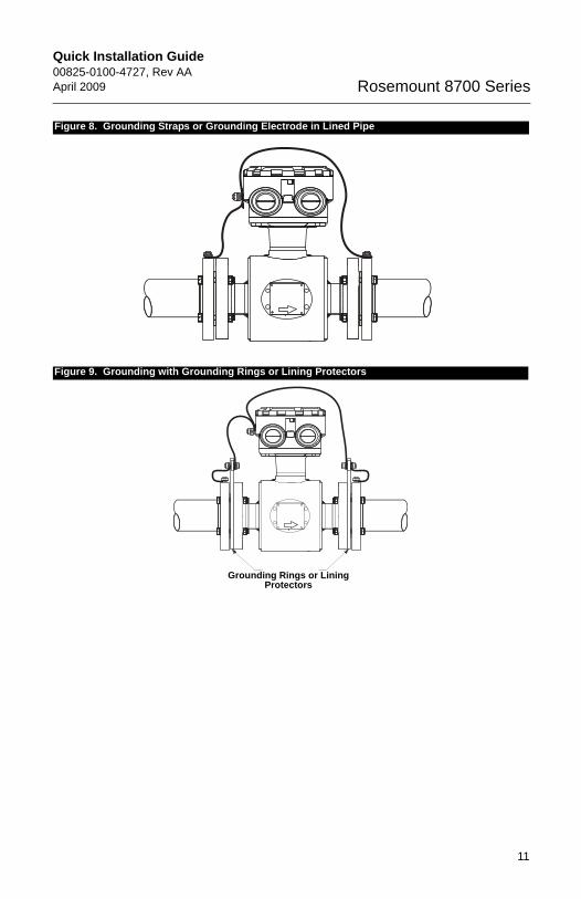
Figure 8. Grounding Straps or Grounding Electrode in Lined Pipe
Figure 9. Grounding with Grounding Rings or Lining Protectors
Grounding Rings or Lining Protectors
11
Quick Installation Guide00825-0100-4727, Rev AA
April 2009Rosemount 8700 Series
4727_revAA_QIG.fm Page 12 Tuesday, April 28, 2009 2:14 PM
STEP 5: WIRINGConduit Ports and ConnectionsBoth the sensor and transmitter junction boxes have ports for 1/2-in. NPT conduit connections with optional CM20 or PG 13.5 connections available. These connections should be made in accordance with national, local, and plant electrical codes. Unused ports should be sealed with metal plugs. Proper electrical installation is necessary to prevent errors due to electrical noise and interference. Separate conduits are not necessary for the coil drive and electrode cables, but a dedicated conduit line between each transmitter and sensor is required. Shielded cable must be used for best results in electrically noisy environments. When preparing all wire connections, remove only the insulation required to fit the wire completely under the terminal connection. Removal of excessive insulation may
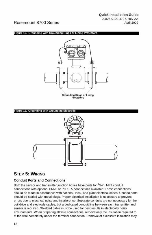
Figure 10. Grounding with Grounding Rings or Lining Protectors
Figure 11. Grounding with Grounding Electrode
Grounding Rings or Lining Protectors
12
Quick Installation Guide00825-0100-4727, Rev AAApril 2009 Rosemount 8700 Series
4727_revAA_QIG.fm Page 13 Tuesday, April 28, 2009 2:14 PM
13
result in an unwanted electrical short to the transmitter housing or other wire connections.For flanged and sanitary sensors installed into an application requiring IP68 protection, sealed cable glands, conduit, and conduit plugs that meet IP68 ratings are required.
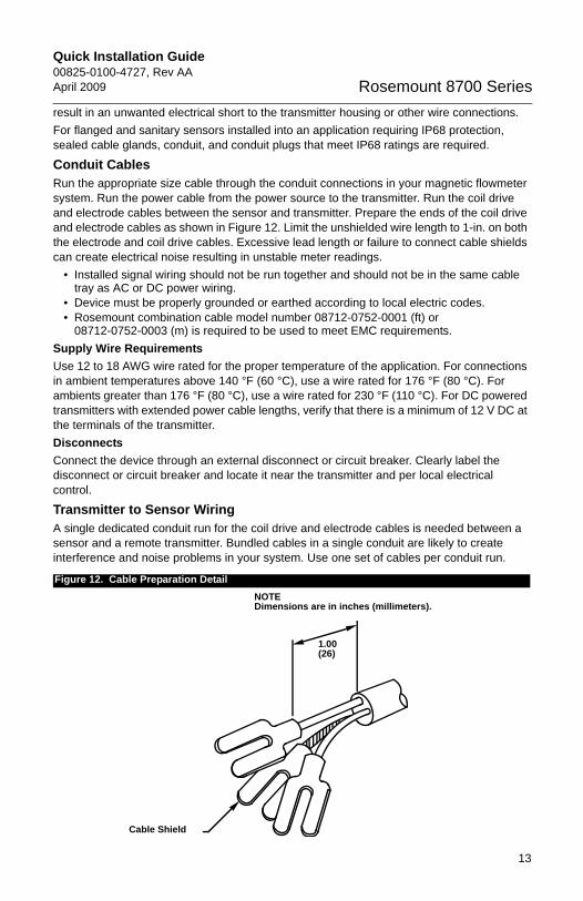
Conduit CablesRun the appropriate size cable through the conduit connections in your magnetic flowmeter system. Run the power cable from the power source to the transmitter. Run the coil drive and electrode cables between the sensor and transmitter. Prepare the ends of the coil drive and electrode cables as shown in Figure 12. Limit the unshielded wire length to 1-in. on both the electrode and coil drive cables. Excessive lead length or failure to connect cable shields can create electrical noise resulting in unstable meter readings.
• Installed signal wiring should not be run together and should not be in the same cable tray as AC or DC power wiring.
• Device must be properly grounded or earthed according to local electric codes.• Rosemount combination cable model number 08712-0752-0001 (ft) or
08712-0752-0003 (m) is required to be used to meet EMC requirements.Supply Wire RequirementsUse 12 to 18 AWG wire rated for the proper temperature of the application. For connections in ambient temperatures above 140 °F (60 °C), use a wire rated for 176 °F (80 °C). For ambients greater than 176 °F (80 °C), use a wire rated for 230 °F (110 °C). For DC powered transmitters with extended power cable lengths, verify that there is a minimum of 12 V DC at the terminals of the transmitter.DisconnectsConnect the device through an external disconnect or circuit breaker. Clearly label the disconnect or circuit breaker and locate it near the transmitter and per local electrical control.
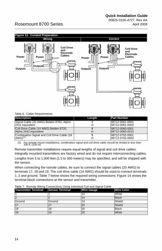
Transmitter to Sensor WiringA single dedicated conduit run for the coil drive and electrode cables is needed between a sensor and a remote transmitter. Bundled cables in a single conduit are likely to create interference and noise problems in your system. Use one set of cables per conduit run.
Figure 12. Cable Preparation Detail
Cable Shield
1.00(26)
NOTEDimensions are in inches (millimeters).
Quick Installation Guide00825-0100-4727, Rev AA
April 2009Rosemount 8700 Series
4727_revAA_QIG.fm Page 14 Tuesday, April 28, 2009 2:14 PM
Remote transmitter installations require equal lengths of signal and coil drive cables. Integrally mounted transmitters are factory wired and do not require interconnecting cables.Lengths from 5 to 1,000 feet (1.5 to 300 meters) may be specified, and will be shipped with the sensor.When connecting the remote cables, be sure to connect the signal cables (20 AWG) to terminals 17, 18 and 19. The coil drive cable (14 AWG) should be used to connect terminals 1, 2 and ground. Table 7 below shows the required wiring connections. Figure 14 shows the terminal block connections at the sensor and transmitter.
Table 7. Remote Wiring Connections Using Individual Coil and Signal Cable
Figure 13. Conduit PreparationWrong Correct
Table 6. Cable RequirementsDescription Length Part NumberSignal Cable (20 AWG) Belden 8762, Alpha 2411 equivalent
ftm
08712-0061-000108712-0061-0003
Coil Drive Cable (14 AWG) Belden 8720, Alpha 2442 equivalent
ftm
08712-0060-000108712-0060-0013
Combination Signal and Coil Drive Cable (18 AWG)(1)
(1) For remote mount installations, combination signal and coil drive cable should be limited to less than 330 ft. (100 m)
ftm
08712-0752-000108712-0752-0003
Transmitter Terminal Sensor Terminal Wire Gauge Wire Color1 1 14 White2 2 14 BlackGround Ground 14 Shield17 17 20 Shield 18 18 20 Black19 19 20 White
Coil Drive and Electrode CablesPower
Outputs
Power
Outputs
Coil Drive and Electrode CablesPower
Outputs
Power
Outputs
14
Quick Installation Guide00825-0100-4727, Rev AAApril 2009 Rosemount 8700 Series
4727_revAA_QIG.fm Page 15 Tuesday, April 28, 2009 2:14 PM
15
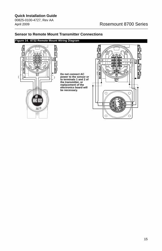
Sensor to Remote Mount Transmitter ConnectionsFigure 14. 8732 Remote Mount Wiring Diagram
Do not connect AC power to the sensor or to terminals 1 and 2 of the transmitter, or replacement of the electronics board will be necessary.
Quick Installation Guide00825-0100-4727, Rev AA
April 2009Rosemount 8700 Series
4727_revAA_QIG.fm Page 16 Tuesday, April 28, 2009 2:14 PM
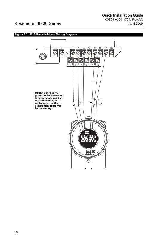
Figure 15. 8712 Remote Mount Wiring Diagram
Do not connect AC power to the sensor or to terminals 1 and 2 of the transmitter, or replacement of the electronics board will be necessary.
16
Quick Installation Guide00825-0100-4727, Rev AAApril 2009 Rosemount 8700 Series
4727_revAA_QIG.fm Page 17 Tuesday, April 28, 2009 2:14 PM
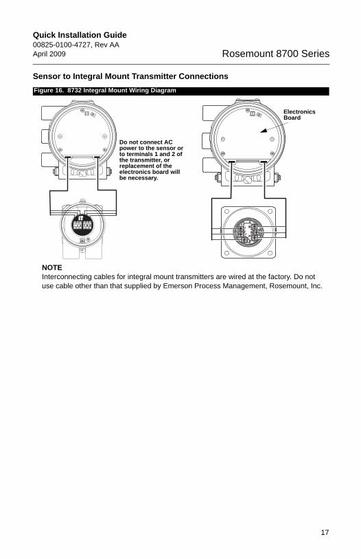
Sensor to Integral Mount Transmitter ConnectionsFigure 16. 8732 Integral Mount Wiring Diagram
Electronics Board
Do not connect AC power to the sensor or to terminals 1 and 2 of the transmitter, or replacement of the electronics board will be necessary.
NOTEInterconnecting cables for integral mount transmitters are wired at the factory. Do not use cable other than that supplied by Emerson Process Management, Rosemount, Inc.
17
Quick Installation Guide00825-0100-4727, Rev AA
April 2009Rosemount 8700 Series
4727_revAA_QIG.fm Page 18 Tuesday, April 28, 2009 2:14 PM
Product CertificationsApproved Manufacturing LocationsRosemount Inc. — Eden Prairie, Minnesota, USAFisher-Rosemount Technologias de Flujo, S.A. de C.V. —
Chihuahua MexicoEmerson Process Management Flow — Ede, The NetherlandsAsia Flow Technologies Center — Nanjing, China
European Directive InformationThe EC Declaration of Conformity can be found on page 25. The most recent revision can be found at www.rosemount.com.
ATEX DirectiveRosemount Inc. complies with the ATEX Directive.Type n protection type in accordance with EN50021
• Closing of entries in the device must be carried out using the appropriate EEx e or EEx n metal cable gland and metal blanking plug or any appropriate ATEX approved cable gland and blanking plug with IP66 rating certified by an EU approved certification body.
European Pressure Equipment Directive (PED) (97/23/EC)
Rosemount 8705 and 8707 Magnetic Flowmeter sensors in line size and flange combinations:
Line Size: 11/2 in. - 24 in. with all DIN flanges and ANSI 150 and ANSI 300 flanges. Also available with ANSI 600 flanges in limited line sizes.
Line Size: 30 in. - 36 in. with AWWA 125 flangesQS Certificate of Assessment - EC No. PED-H-100Module H Conformity Assessment
Rosemount 8711 Magnetic Flowmeter Sensors Line Sizes: 1.5, 2, 3, 4, 6, and 8 in.QS Certificate of Assessment - EC No. PED-H-100Module H Conformity Assessment
Rosemount 8721 Sanitary Magmeter Sensors in line sizes of 11/2 in. and larger:Module H Conformity Assessment
All other Rosemount 8705/8707/8711/8721 Sensors — in line sizes of 1 in. and less:Sound Engineering Practice
18
Quick Installation Guide00825-0100-4727, Rev AAApril 2009 Rosemount 8700 Series
4727_revAA_QIG.fm Page 19 Tuesday, April 28, 2009 2:14 PM
Sensors that are SEP are outside the scope of PED and cannot be marked for compliance with PED.Mandatory CE-marking for sensors in accordance with Article 15 of the PED can be found on the sensor body ( 0575). Sensor category I is assessed for conformity per module A procedures.Sensor categories II – IV, use module H for conformity assessment procedures.
Other important guidelines Only use new, original parts. To prevent the process medium escaping, do not unscrew or remove process flange bolts, adapter bolts or bleed screws during operation. Maintenance shall only be done by qualified personnel.
Marking Compliance with all applicable European Union Directives. (Note: Marking is not available on Rosemount 8712H).
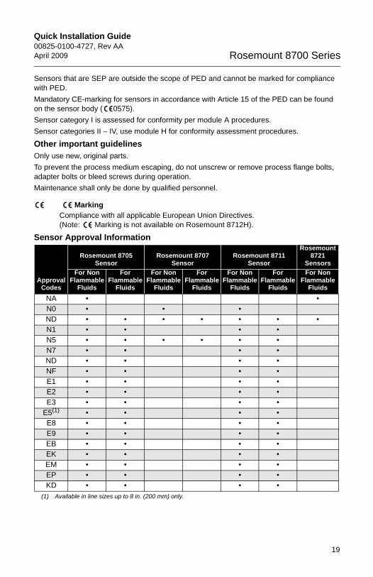
Sensor Approval Information
Approval Codes
Rosemount 8705 Sensor
Rosemount 8707 Sensor
Rosemount 8711 Sensor
Rosemount 8721
SensorsFor Non
Flammable Fluids
For Flammable
Fluids
For Non Flammable
Fluids
For Flammable
Fluids
For Non Flammable
Fluids
For Flammable
Fluids
For Non Flammable
FluidsNA • •N0 • • •ND • • • • • • •N1 • • • •N5 • • • • • •N7 • • • •ND • • • •NF • • • •E1 • • • •E2 • • • •E3 • • • •
E5(1)
(1) Available in line sizes up to 8 in. (200 mm) only.
• • • •E8 • • • •E9 • • • •EB • • • •EK • • • •EM • • • •EP • • • •KD • • • •
19
Quick Installation Guide00825-0100-4727, Rev AA
April 2009Rosemount 8700 Series
4727_revAA_QIG.fm Page 20 Tuesday, April 28, 2009 2:14 PM
20
North American Certifications
Factory Mutual (FM)N0 Non-incendive for Class I, Division 2, Groups A, B, C, and D non-flammable fluids
(8705/8711 T5 at 60 °C; 8707 T3C at 60 °C), and Dust-ignition proof Class II/III, Division 1, Groups E, F, and G (8705/8711 T6 at 60 °C; 8707 T3C at 60 °C) Hazardous locations; Enclosure Type 4X
N0 8721 Hygienic SensorFactory Mutual (FM) Ordinary Location; CE Marking; 3-A Symbol Authorization #1222;EHEDG Type EL
N5 Non-incendive for Class I, Division 2, Groups A, B, C, and D; with intrinsically safe electrodes for use on flammable fluids (8705/8711 T5 at 60 °C; 8707 T3C at 60 °C), and Dust-ignition proof Class II/III, Division 1, Groups E, F, and G (8705/8711 T6 at 60 °C; 8707 T3C at 60 °C) Hazardous locations; Enclosure Type 4X
E5 Explosion proof for Class I, Division 1, Groups C and D (8705/8711 T6 at 60 °C), and Dust-ignition proof Class II/III, Division 1, Groups E, F, and G (8705/8711 T6 at 60 °C), and non-incendive for Class I, Division 2, Groups A, B, C, and D flammable fluids (8705/8711 T5 at 60 °C) Hazardous locations; Enclosure Type 4X
Canadian Standards Association (CSA)N0 Non-incendive for Class I, Division 2, Groups A, B, C, and D non-flammable fluids
(8705/8711 T5 at 60 °C; 8707 T3C at 60 °C), and Dust-ignition proof Class II/III, Division 1, Groups E, F, and G (8705/8711 T6 at 60 °C; 8707 T3C at 60 °C) Hazardous locations; Enclosure Type 4X
N0 8721 Hygienic SensorCanadian Standards Association (CSA) Ordinary Location; CE Marking; 3-A Symbol Authorization #1222;EHEDG Type EL
European CertificationsND ATEX Dust Certificate No.: KEMA 06ATEX0006
II 1D max. ΔT = 40 K IP66 Amb. Temp. Limits: (-20 °C = Ta = +65 °C)
0575
Installation InstructionsThe cable and conduit entry devices and blanking elements shall be of a certified IP66 type, suitable for the conditions of use and correctly installed.At maximum ambient temperatures, or at process temperatures above 60 °C, heat resistant cables with a temperature rating of at least 90 °C shall be used.
N1 ATEX Non-Sparking/Non-incendiveCertificate No: KEMA02ATEX1302X
II 3G EEx nA [L] IIC T3... T6Ambient Temperature Limits -20 to 65 °C
Quick Installation Guide00825-0100-4727, Rev AAApril 2009 Rosemount 8700 Series
4727_revAA_QIG.fm Page 21 Tuesday, April 28, 2009 2:14 PM
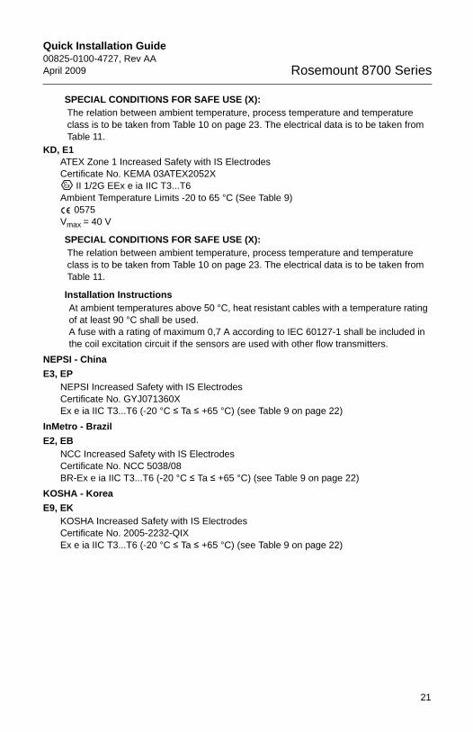
SPECIAL CONDITIONS FOR SAFE USE (X):The relation between ambient temperature, process temperature and temperature class is to be taken from Table 10 on page 23. The electrical data is to be taken from Table 11.
KD, E1ATEX Zone 1 Increased Safety with IS ElectrodesCertificate No. KEMA 03ATEX2052X
II 1/2G EEx e ia IIC T3...T6 Ambient Temperature Limits -20 to 65 °C (See Table 9)
0575Vmax = 40 V
SPECIAL CONDITIONS FOR SAFE USE (X):The relation between ambient temperature, process temperature and temperature class is to be taken from Table 10 on page 23. The electrical data is to be taken from Table 11.
Installation InstructionsAt ambient temperatures above 50 °C, heat resistant cables with a temperature rating of at least 90 °C shall be used.A fuse with a rating of maximum 0,7 A according to IEC 60127-1 shall be included in the coil excitation circuit if the sensors are used with other flow transmitters.
NEPSI - ChinaE3, EP
NEPSI Increased Safety with IS ElectrodesCertificate No. GYJ071360X Ex e ia IIC T3...T6 (-20 °C ≤ Ta ≤ +65 °C) (see Table 9 on page 22)
InMetro - BrazilE2, EB
NCC Increased Safety with IS ElectrodesCertificate No. NCC 5038/08BR-Ex e ia IIC T3...T6 (-20 °C ≤ Ta ≤ +65 °C) (see Table 9 on page 22)
KOSHA - KoreaE9, EK
KOSHA Increased Safety with IS ElectrodesCertificate No. 2005-2232-QIXEx e ia IIC T3...T6 (-20 °C ≤ Ta ≤ +65 °C) (see Table 9 on page 22)
21
Quick Installation Guide00825-0100-4727, Rev AA
April 2009Rosemount 8700 Series
4727_revAA_QIG.fm Page 22 Tuesday, April 28, 2009 2:14 PM
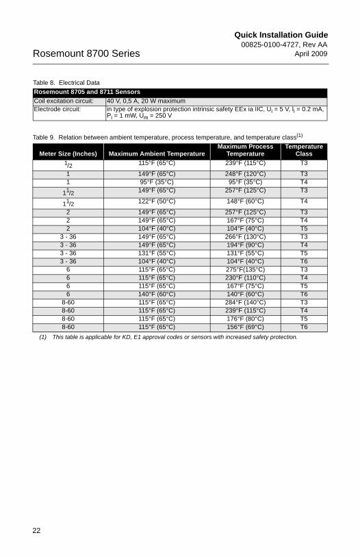
Table 8. Electrical DataRosemount 8705 and 8711 SensorsCoil excitation circuit: 40 V, 0,5 A, 20 W maximumElectrode circuit: in type of explosion protection intrinsic safety EEx ia IIC, Ui = 5 V, li = 0.2 mA,
Pi = 1 mW, Um = 250 V
Table 9. Relation between ambient temperature, process temperature, and temperature class(1)
(1) This table is applicable for KD, E1 approval codes or sensors with increased safety protection.
Meter Size (Inches) Maximum Ambient TemperatureMaximum Process
TemperatureTemperature
Class1/2 115°F (65°C) 239°F (115°C) T3
1 149°F (65°C) 248°F (120°C) T31 95°F (35°C) 95°F (35°C) T4
11/2 149°F (65°C) 257°F (125°C) T3
11/2 122°F (50°C) 148°F (60°C) T4
2 149°F (65°C) 257°F (125°C) T32 149°F (65°C) 167°F (75°C) T42 104°F (40°C) 104°F (40°C) T5
3 - 36 149°F (65°C) 266°F (130°C) T33 - 36 149°F (65°C) 194°F (90°C) T43 - 36 131°F (55°C) 131°F (55°C) T53 - 36 104°F (40°C) 104°F (40°C) T6
6 115°F (65°C) 275°F(135°C) T36 115°F (65°C) 230°F (110°C) T46 115°F (65°C) 167°F (75°C) T56 140°F (60°C) 140°F (60°C) T6
8-60 115°F (65°C) 284°F (140°C) T38-60 115°F (65°C) 239°F (115°C) T48-60 115°F (65°C) 176°F (80°C) T58-60 115°F (65°C) 156°F (69°C) T6
22
Quick Installation Guide00825-0100-4727, Rev AAApril 2009 Rosemount 8700 Series
4727_revAA_QIG.fm Page 23 Tuesday, April 28, 2009 2:14 PM
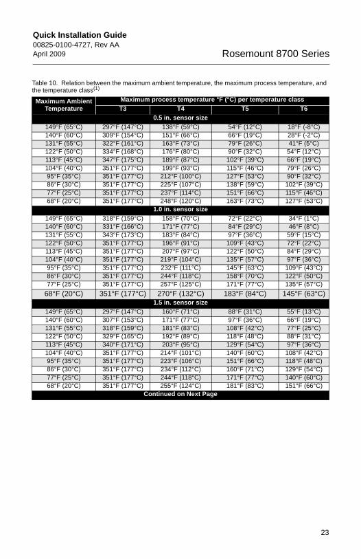
Table 10. Relation between the maximum ambient temperature, the maximum process temperature, and the temperature class(1)
Maximum Ambient Temperature
Maximum process temperature °F (°C) per temperature classT3 T4 T5 T6
0.5 in. sensor size149°F (65°C) 297°F (147°C) 138°F (59°C) 54°F (12°C) 18°F (-8°C)140°F (60°C) 309°F (154°C) 151°F (66°C) 66°F (19°C) 28°F (-2°C)131°F (55°C) 322°F (161°C) 163°F (73°C) 79°F (26°C) 41°F (5°C)122°F (50°C) 334°F (168°C) 176°F (80°C) 90°F (32°C) 54°F (12°C)113°F (45°C) 347°F (175°C) 189°F (87°C) 102°F (39°C) 66°F (19°C)104°F (40°C) 351°F (177°C) 199°F (93°C) 115°F (46°C) 79°F (26°C)95°F (35°C) 351°F (177°C) 212°F (100°C) 127°F (53°C) 90°F (32°C)86°F (30°C) 351°F (177°C) 225°F (107°C) 138°F (59°C) 102°F (39°C)77°F (25°C) 351°F (177°C) 237°F (114°C) 151°F (66°C) 115°F (46°C)68°F (20°C) 351°F (177°C) 248°F (120°C) 163°F (73°C) 127°F (53°C)
1.0 in. sensor size149°F (65°C) 318°F (159°C) 158°F (70°C) 72°F (22°C) 34°F (1°C)140°F (60°C) 331°F (166°C) 171°F (77°C) 84°F (29°C) 46°F (8°C)131°F (55°C) 343°F (173°C) 183°F (84°C) 97°F (36°C) 59°F (15°C)122°F (50°C) 351°F (177°C) 196°F (91°C) 109°F (43°C) 72°F (22°C)113°F (45°C) 351°F (177°C) 207°F (97°C) 122°F (50°C) 84°F (29°C)104°F (40°C) 351°F (177°C) 219°F (104°C) 135°F (57°C) 97°F (36°C)95°F (35°C) 351°F (177°C) 232°F (111°C) 145°F (63°C) 109°F (43°C)86°F (30°C) 351°F (177°C) 244°F (118°C) 158°F (70°C) 122°F (50°C)77°F (25°C) 351°F (177°C) 257°F (125°C) 171°F (77°C) 135°F (57°C)
68°F (20°C) 351°F (177°C) 270°F (132°C) 183°F (84°C) 145°F (63°C)1.5 in. sensor size
149°F (65°C) 297°F (147°C) 160°F (71°C) 88°F (31°C) 55°F (13°C)140°F (60°C) 307°F (153°C) 171°F (77°C) 97°F (36°C) 66°F (19°C)131°F (55°C) 318°F (159°C) 181°F (83°C) 108°F (42°C) 77°F (25°C)122°F (50°C) 329°F (165°C) 192°F (89°C) 118°F (48°C) 88°F (31°C)113°F (45°C) 340°F (171°C) 203°F (95°C) 129°F (54°C) 97°F (36°C)104°F (40°C) 351°F (177°C) 214°F (101°C) 140°F (60°C) 108°F (42°C)95°F (35°C) 351°F (177°C) 223°F (106°C) 151°F (66°C) 118°F (48°C)86°F (30°C) 351°F (177°C) 234°F (112°C) 160°F (71°C) 129°F (54°C)77°F (25°C) 351°F (177°C) 244°F (118°C) 171°F (77°C) 140°F (60°C)68°F (20°C) 351°F (177°C) 255°F (124°C) 181°F (83°C) 151°F (66°C)
Continued on Next Page
23
Quick Installation Guide00825-0100-4727, Rev AA
April 2009Rosemount 8700 Series
4727_revAA_QIG.fm Page 24 Tuesday, April 28, 2009 2:14 PM
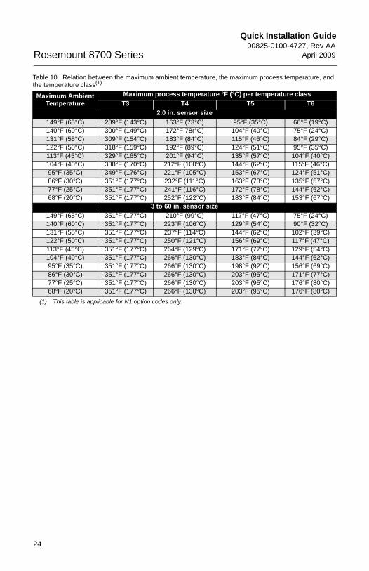
2.0 in. sensor size149°F (65°C) 289°F (143°C) 163°F (73°C) 95°F (35°C) 66°F (19°C)140°F (60°C) 300°F (149°C) 172°F 78(°C) 104°F (40°C) 75°F (24°C)131°F (55°C) 309°F (154°C) 183°F (84°C) 115°F (46°C) 84°F (29°C)122°F (50°C) 318°F (159°C) 192°F (89°C) 124°F (51°C) 95°F (35°C)113°F (45°C) 329°F (165°C) 201°F (94°C) 135°F (57°C) 104°F (40°C)104°F (40°C) 338°F (170°C) 212°F (100°C) 144°F (62°C) 115°F (46°C)95°F (35°C) 349°F (176°C) 221°F (105°C) 153°F (67°C) 124°F (51°C)86°F (30°C) 351°F (177°C) 232°F (111°C) 163°F (73°C) 135°F (57°C)77°F (25°C) 351°F (177°C) 241°F (116°C) 172°F (78°C) 144°F (62°C)68°F (20°C) 351°F (177°C) 252°F (122°C) 183°F (84°C) 153°F (67°C)
3 to 60 in. sensor size149°F (65°C) 351°F (177°C) 210°F (99°C) 117°F (47°C) 75°F (24°C)140°F (60°C) 351°F (177°C) 223°F (106°C) 129°F (54°C) 90°F (32°C)131°F (55°C) 351°F (177°C) 237°F (114°C) 144°F (62°C) 102°F (39°C)122°F (50°C) 351°F (177°C) 250°F (121°C) 156°F (69°C) 117°F (47°C)113°F (45°C) 351°F (177°C) 264°F (129°C) 171°F (77°C) 129°F (54°C)104°F (40°C) 351°F (177°C) 266°F (130°C) 183°F (84°C) 144°F (62°C)95°F (35°C) 351°F (177°C) 266°F (130°C) 198°F (92°C) 156°F (69°C)86°F (30°C) 351°F (177°C) 266°F (130°C) 203°F (95°C) 171°F (77°C)77°F (25°C) 351°F (177°C) 266°F (130°C) 203°F (95°C) 176°F (80°C)68°F (20°C) 351°F (177°C) 266°F (130°C) 203°F (95°C) 176°F (80°C)
(1) This table is applicable for N1 option codes only.
Table 10. Relation between the maximum ambient temperature, the maximum process temperature, and the temperature class(1)
Maximum Ambient Temperature
Maximum process temperature °F (°C) per temperature classT3 T4 T5 T6
24
Quick Installation Guide00825-0100-4727, Rev AAApril 2009 Rosemount 8700 Series
4727_revAA_QIG.fm Page 25 Tuesday, April 28, 2009 2:14 PM
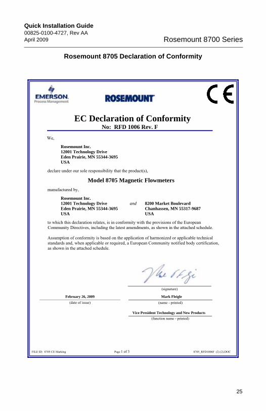
Rosemount 8705 Declaration of Conformity
EC Declaration of Conformity No: RFD 1006 Rev. F
FILE ID: 8705 CE Marking Page 1 of 3 8705_RFD1006F (2) (2).DOC
We,
Rosemount Inc. 12001 Technology Drive Eden Prairie, MN 55344-3695 USA
declare under our sole responsibility that the product(s),
Model 8705 Magnetic Flowmeters manufactured by,
Rosemount Inc. 12001 Technology Drive and 8200 Market Boulevard Eden Prairie, MN 55344-3695 Chanhassen, MN 55317-9687 USA USA
to which this declaration relates, is in conformity with the provisions of the European Community Directives, including the latest amendments, as shown in the attached schedule. Assumption of conformity is based on the application of harmonized or applicable technical standards and, when applicable or required, a European Community notified body certification, as shown in the attached schedule.
Mark Fleigle
Vice President Technology and New Products
February 26, 2009 (date of issue) (name - printed)
(function name - printed)
(signature)
25
Quick Installation Guide00825-0100-4727, Rev AA
April 2009Rosemount 8700 Series
4727_revAA_QIG.fm Page 26 Tuesday, April 28, 2009 2:14 PM
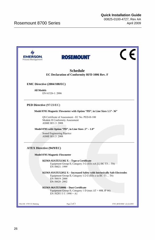
ScheduleEC Declaration of Conformity RFD 1006 Rev. F
FILE ID: 8705 CE Marking Page 2 of 3 8705_RFD1006F (2) (2).DOC
EMC Directive (2004/108/EC)
All ModelsEN 61326-1: 2006
PED Directive (97/23/EC)
Model 8705 Magnetic Flowmeter with Option “PD”, in Line Sizes 1.5”- 36”
QS Certificate of Assessment - EC No. PED-H-100Module H Conformity Assessment ASME B31.3: 2008
Model 8705 with Option “PD”, in Line Sizes .5” – 1.0”
Sound Engineering Practice ASME B31.3: 2008
ATEX Directive (94/9/EC)
Model 8705 Magnetic Flowmeter
KEMA 02ATEX1302 X – Type n Certificate Equipment Group II, Category 3 G (EEx nA [L] IIC T3… T6) EN 50021: 1999
KEMA 03ATEX2052 X – Increased Safety with Intrinsically Safe Electrodes Equipment Group II, Category 1/2 G (EEx e ia IIC T3… T6) EN 50019: 2000 EN 50020: 2002
KEMA 06ATEX0006 – Dust Certificate Equipment Group II, Category 1 D (max �T = 40K IP 66) EN 50281-1-1: 1998 + A1
26
Quick Installation Guide00825-0100-4727, Rev AAApril 2009 Rosemount 8700 Series
4727_revAA_QIG.fm Page 27 Tuesday, April 28, 2009 2:14 PM
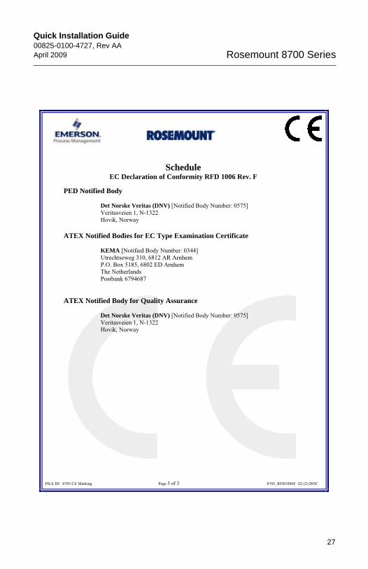
ScheduleEC Declaration of Conformity RFD 1006 Rev. F
FILE ID: 8705 CE Marking Page 3 of 3 8705_RFD1006F (2) (2).DOC
PED Notified Body
Det Norske Veritas (DNV) [Notified Body Number: 0575] Veritasveien 1, N-1322
Hovik, Norway
ATEX Notified Bodies for EC Type Examination Certificate
KEMA [Notified Body Number: 0344] Utrechtseweg 310, 6812 AR Arnhem
P.O. Box 5185, 6802 ED Arnhem The Netherlands Postbank 6794687
ATEX Notified Body for Quality Assurance
Det Norske Veritas (DNV) [Notified Body Number: 0575] Veritasveien 1, N-1322
Hovik, Norway
27
Quick Installation Guide00825-0100-4727, Rev AA
April 2009Rosemount 8700 Series
4727_revAA_QIG.fm Page 28 Tuesday, April 28, 2009 2:14 PM
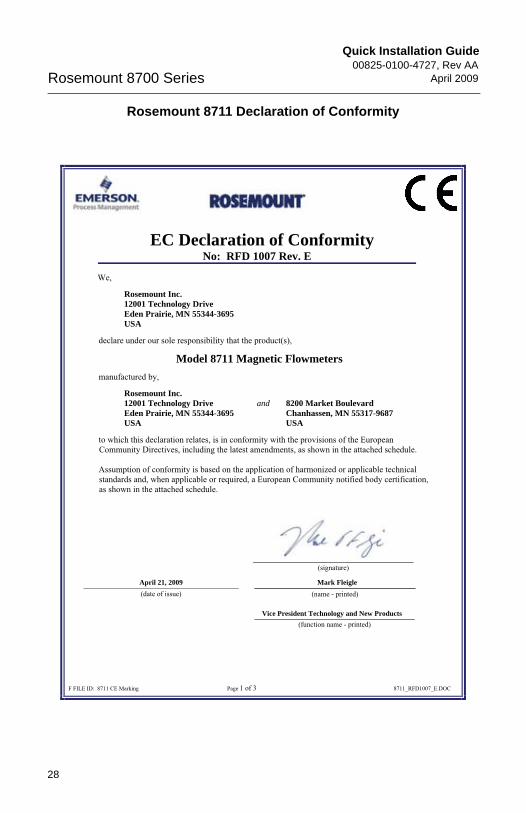
Rosemount 8711 Declaration of Conformity
EC Declaration of Conformity No: RFD 1007 Rev. E
F FILE ID: 8711 CE Marking Page 1 of 3 8711_RFD1007_E.DOC
We,
Rosemount Inc. 12001 Technology Drive Eden Prairie, MN 55344-3695 USA
declare under our sole responsibility that the product(s),
Model 8711 Magnetic Flowmeters manufactured by,
Rosemount Inc. 12001 Technology Drive and 8200 Market Boulevard Eden Prairie, MN 55344-3695 Chanhassen, MN 55317-9687 USA USA
to which this declaration relates, is in conformity with the provisions of the European Community Directives, including the latest amendments, as shown in the attached schedule. Assumption of conformity is based on the application of harmonized or applicable technical standards and, when applicable or required, a European Community notified body certification, as shown in the attached schedule.
(signature)
Mark Fleigle April 21, 2009
Vice President Technology and New Products
(date of issue) (name - printed)
(function name - printed)
28
Quick Installation Guide00825-0100-4727, Rev AAApril 2009 Rosemount 8700 Series
4727_revAA_QIG.fm Page 29 Tuesday, April 28, 2009 2:14 PM
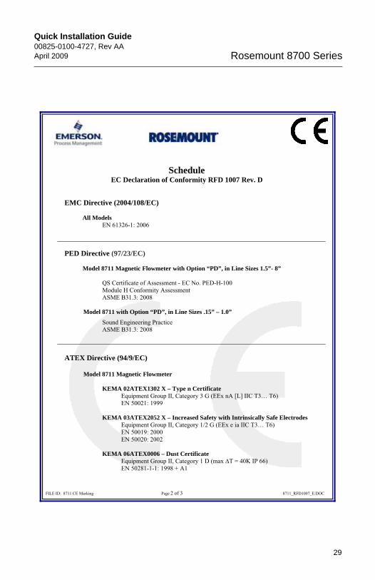
ScheduleEC Declaration of Conformity RFD 1007 Rev. D
FILE ID: 8711 CE Marking Page 2 of 3 8711_RFD1007_E.DOC
EMC Directive (2004/108/EC)
All ModelsEN 61326-1: 2006
PED Directive (97/23/EC)
Model 8711 Magnetic Flowmeter with Option “PD”, in Line Sizes 1.5”- 8”
QS Certificate of Assessment - EC No. PED-H-100Module H Conformity Assessment ASME B31.3: 2008
Model 8711 with Option “PD”, in Line Sizes .15” – 1.0”
Sound Engineering Practice ASME B31.3: 2008
ATEX Directive (94/9/EC)
Model 8711 Magnetic Flowmeter
KEMA 02ATEX1302 X – Type n Certificate Equipment Group II, Category 3 G (EEx nA [L] IIC T3… T6) EN 50021: 1999
KEMA 03ATEX2052 X – Increased Safety with Intrinsically Safe Electrodes Equipment Group II, Category 1/2 G (EEx e ia IIC T3… T6) EN 50019: 2000 EN 50020: 2002
KEMA 06ATEX0006 – Dust Certificate Equipment Group II, Category 1 D (max �T = 40K IP 66) EN 50281-1-1: 1998 + A1
29
Quick Installation Guide00825-0100-4727, Rev AA
April 2009Rosemount 8700 Series
4727_revAA_QIG.fm Page 30 Tuesday, April 28, 2009 2:14 PM
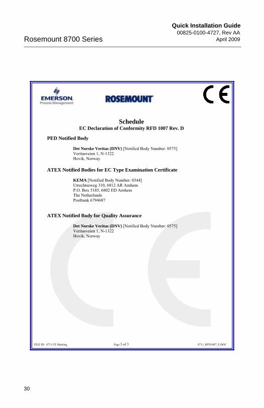
ScheduleEC Declaration of Conformity RFD 1007 Rev. D
FILE ID: 8711 CE Marking Page 3 of 3 8711_RFD1007_E.DOC
PED Notified Body
Det Norske Veritas (DNV) [Notified Body Number: 0575] Veritasveien 1, N-1322
Hovik, Norway
ATEX Notified Bodies for EC Type Examination Certificate
KEMA [Notified Body Number: 0344] Utrechtseweg 310, 6812 AR Arnhem
P.O. Box 5185, 6802 ED Arnhem The Netherlands Postbank 6794687
ATEX Notified Body for Quality Assurance
Det Norske Veritas (DNV) [Notified Body Number: 0575] Veritasveien 1, N-1322
Hovik, Norway
30
Quick Installation Guide00825-0100-4727, Rev AAApril 2009 Rosemount 8700 Series
4727_revAA_QIG.fm Page 31 Tuesday, April 28, 2009 2:14 PM
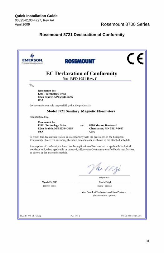
Rosemount 8721 Declaration of Conformity
EC Declaration of Conformity No: RFD 1051 Rev. C
FILE ID: 8721 CE Marking Page 1 of 2 8721_RFD1051_C (3).DOC
We,
Rosemount Inc. 12001 Technology Drive Eden Prairie, MN 55344-3695 USA
declare under our sole responsibility that the product(s),
Model 8721 Sanitary Magnetic Flowmeters manufactured by,
Rosemount Inc. 12001 Technology Drive and 8200 Market Boulevard Eden Prairie, MN 55344-3695 Chanhassen, MN 55317-9687 USA USA
to which this declaration relates, is in conformity with the provisions of the European Community Directives, including the latest amendments, as shown in the attached schedule.
Assumption of conformity is based on the application of harmonized or applicable technical standards and, when applicable or required, a European Community notified body certification, as shown in the attached schedule.
Mark Fleigle
Vice President Technology and New Products
March 19, 2009 (date of issue) (name - printed)
(function name - printed)
(signature)
31
Quick Installation Guide00825-0100-4727, Rev AA
April 2009Rosemount 8700 Series
4727_revAA_QIG.fm Page 32 Tuesday, April 28, 2009 2:14 PM
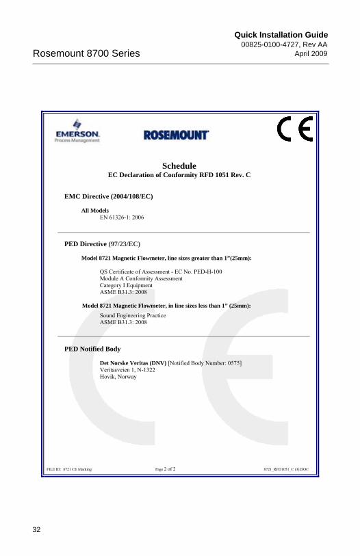
ScheduleEC Declaration of Conformity RFD 1051 Rev. C
FILE ID: 8721 CE Marking Page 2 of 2 8721_RFD1051_C (3).DOC
EMC Directive (2004/108/EC)
All ModelsEN 61326-1: 2006
PED Directive (97/23/EC)
Model 8721 Magnetic Flowmeter, line sizes greater than 1”(25mm):
QS Certificate of Assessment - EC No. PED-H-100Module A Conformity Assessment Category I Equipment ASME B31.3: 2008
Model 8721 Magnetic Flowmeter, in line sizes less than 1” (25mm):Sound Engineering Practice ASME B31.3: 2008
PED Notified Body
Det Norske Veritas (DNV) [Notified Body Number: 0575] Veritasveien 1, N-1322
Hovik, Norway
32