Embed Size (px)
Citation preview

Product Data Sheet00813-0100-4727, Rev UCJune 2010 Rosemount 8700 Series
www.rosemount.com
• Industry leading performance with standard reference accuracy of 0.25% of rate with an optional High Accuracy of 0.15% of rate.
• Rosemount 8732 Transmitter - Integral-mount design, backlit display, and explosion-proof housing. Available with HART®, FOUNDATION™ fieldbus, or Profibus-PA, I.S. Outputs, Device Diagnostics, and SMART™ Meter Verification to improve reliability and performance
• Rosemount 8712 HART Transmitter - available with Device Diagnostics including SMART Meter Verification to improve reliability and performance. Quick setup with easy-to-use local operator interface
• Rosemount 8712H/8707 High-Signal System - Pulsed DC solutions for the most demanding flow measurement applications
• Rosemount 8705 Flanged sensor - Fully welded sensor for maximum protection (standard ISO lay length)
• Rosemount 8711 Wafer sensor - Economical, compact, and lightweight sensor, provided with alignment rings for easy installation
• Rosemount 8721 Hygienic sensor - Specifically designed for food, beverage, and life sciences applications
ContentsProduct Selection Guide . . . . . . . . . . . . . . . . . . . . . . . . . . . . . . . . . . . . . . . . . . . . . . . . . . . . .page 2
Magnetic Flowmeter Sizing. . . . . . . . . . . . . . . . . . . . . . . . . . . . . . . . . . . . . . . . . . . . . . . . . . .page 4
Ordering Information. . . . . . . . . . . . . . . . . . . . . . . . . . . . . . . . . . . . . . . . . . . . . . . . . . . . . . . .page 6
Rosemount 8700 Series Product Specifications Overview. . . . . . . . . . . . . . . . . . . . . . . . . .page 25
Product Certifications . . . . . . . . . . . . . . . . . . . . . . . . . . . . . . . . . . . . . . . . . . . . . . . . . . . . . .page 48
Dimensional Drawings . . . . . . . . . . . . . . . . . . . . . . . . . . . . . . . . . . . . . . . . . . . . . . . . . . . . .page 60
Rosemount 8700 SeriesMagnetic Flowmeter Systems
Product Data Sheet00813-0100-4727, Rev UC
June 2010Rosemount 8700 Series
2
Product Selection Guide
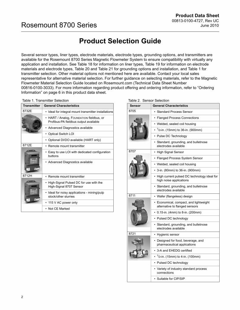
Several sensor types, liner types, electrode materials, electrode types, grounding options, and transmitters are available for the Rosemount 8700 Series Magnetic Flowmeter System to ensure compatibility with virtually any application and installation. See Table 18 for information on liner types, Table 19 for information on electrode materials and electrode types, Table 20 and Table 21 for grounding options and installation, and Table 1 for transmitter selection. Other material options not mentioned here are available. Contact your local sales representative for alternative material selection. For further guidance on selecting materials, refer to the Magnetic Flowmeter Material Selection Guide located on Rosemount.com (Technical Data Sheet Number 00816-0100-3033). For more information regarding product offering and ordering information, refer to “Ordering Information” on page 6 in this product data sheet.
Table 1. Transmitter Selection Table 2. Sensor SelectionTransmitter General Characteristics8732E • Ideal for integral mount transmitter installations
• HART / Analog, FOUNDATION fieldbus, or Profibus-PA fieldbus output available
• Advanced Diagnostics available
• Optical Switch LOI
• Optional DI/DO available (HART only)
8712E • Remote mount transmitter
• Easy to use LOI with dedicated configuration buttons
• Advanced Diagnostics available
8712H • Remote mount transmitter
• High-Signal Pulsed DC for use with the High-Signal 8707 Sensor
• Ideal for noisy applications - mining/pulp stock/other slurries
• 115 V AC power only
• Not CE Marked
Sensor General Characteristics8705 • Standard Process Sensor
• Flanged Process Connections
• Welded, sealed coil housing
• 1/2-in. (15mm) to 36-in. (900mm)
• Pulse DC Technology
• Standard, grounding, and bulletnose electrodes available
8707 • High Signal Sensor
• Flanged Process System Sensor
• Welded, sealed coil housing
• 3-in. (80mm) to 36-in. (900mm)
• High current pulsed DC technology ideal for high noise applications
• Standard, grounding, and bulletnose electrodes available
8711 • Wafer (flangeless) design
• Economical, compact, and lightweight alternative to flanged sensors
• 0.15-in. (4mm) to 8-in. (200mm)
• Pulsed DC technology
• Standard, grounding, and bulletnose electrodes available
8721 • Hygienic sensor
• Designed for food, beverage, and pharmaceutical applications
• 3-A and EHEDG certified
• 1/2-in. (15mm) to 4-in. (100mm)
• Pulsed DC technology
• Variety of industry standard process connections
• Suitable for CIP/SIP
Product Data Sheet00813-0100-4727, Rev UCJune 2010
3
Rosemount 8700 SeriesRosemount Magmeter Diagnostics Power PlantWeb
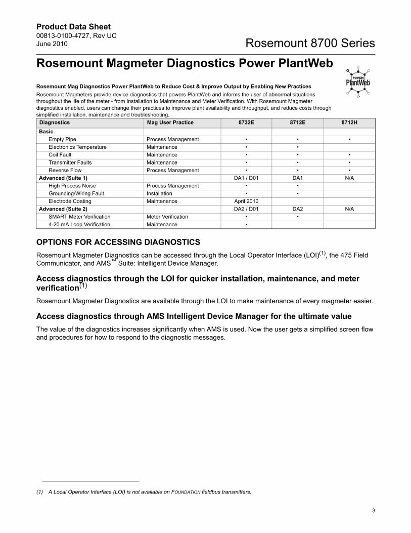
Rosemount Mag Diagnostics Power PlantWeb to Reduce Cost & Improve Output by Enabling New Practices Rosemount Magmeters provide device diagnostics that powers PlantWeb and informs the user of abnormal situations throughout the life of the meter - from Installation to Maintenance and Meter Verification. With Rosemount Magmeter diagnostics enabled, users can change their practices to improve plant availability and throughput, and reduce costs through simplified installation, maintenance and troubleshooting.
OPTIONS FOR ACCESSING DIAGNOSTICSRosemount Magmeter Diagnostics can be accessed through the Local Operator Interface (LOI)(1), the 475 Field Communicator, and AMS™ Suite: Intelligent Device Manager.
Access diagnostics through the LOI for quicker installation, maintenance, and meter verification(1)
Rosemount Magmeter Diagnostics are available through the LOI to make maintenance of every magmeter easier.
Access diagnostics through AMS Intelligent Device Manager for the ultimate valueThe value of the diagnostics increases significantly when AMS is used. Now the user gets a simplified screen flow and procedures for how to respond to the diagnostic messages.
Diagnostics Mag User Practice 8732E 8712E 8712HBasic
Empty Pipe Process Management • • •Electronics Temperature Maintenance • •Coil Fault Maintenance • • •Transmitter Faults Maintenance • • •Reverse Flow Process Management • • •
Advanced (Suite 1) DA1 / D01 DA1 N/AHigh Process Noise Process Management • •Grounding/Wiring Fault Installation • •Electrode Coating Maintenance April 2010
Advanced (Suite 2) DA2 / D01 DA2 N/ASMART Meter Verification Meter Verification • •4-20 mA Loop Verification Maintenance •
(1) A Local Operator Interface (LOI) is not available on FOUNDATION fieldbus transmitters.
Product Data Sheet00813-0100-4727, Rev UC
June 2010Rosemount 8700 Series
4
Magnetic Flowmeter Sizing
Flowmeter Sizing
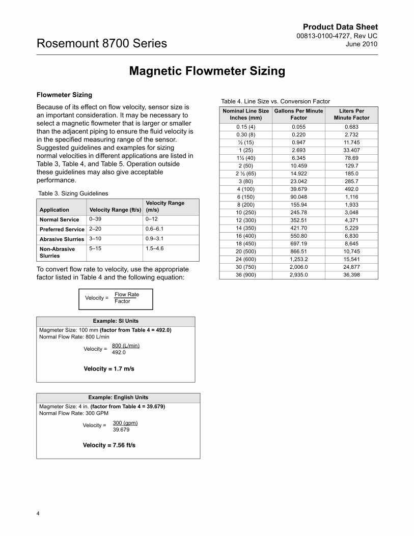
Because of its effect on flow velocity, sensor size is an important consideration. It may be necessary to select a magnetic flowmeter that is larger or smaller than the adjacent piping to ensure the fluid velocity is in the specified measuring range of the sensor. Suggested guidelines and examples for sizing normal velocities in different applications are listed in Table 3, Table 4, and Table 5. Operation outside these guidelines may also give acceptable performance.
To convert flow rate to velocity, use the appropriate factor listed in Table 4 and the following equation:
Table 3. Sizing Guidelines
Application Velocity Range (ft/s)Velocity Range (m/s)
Normal Service 0–39 0–12
Preferred Service 2–20 0.6–6.1
Abrasive Slurries 3–10 0.9–3.1
Non-Abrasive Slurries
5–15 1.5–4.6
Example: SI UnitsMagmeter Size: 100 mm (factor from Table 4 = 492.0)Normal Flow Rate: 800 L/min
Example: English UnitsMagmeter Size: 4 in. (factor from Table 4 = 39.679)Normal Flow Rate: 300 GPM
Velocity = Flow RateFactor
Velocity =
Velocity = 1.7 m/s
800 (L/min)492.0
Velocity =
Velocity = 7.56 ft/s
300 (gpm)39.679
Table 4. Line Size vs. Conversion FactorNominal Line Size
Inches (mm)Gallons Per Minute
FactorLiters Per
Minute Factor0.15 (4) 0.055 0.6830.30 (8) 0.220 2.732½ (15) 0.947 11.7451 (25) 2.693 33.407
1½ (40) 6.345 78.692 (50) 10.459 129.7
2 ½ (65) 14.922 185.03 (80) 23.042 285.7
4 (100) 39.679 492.06 (150) 90.048 1,1168 (200) 155.94 1,933
10 (250) 245.78 3,04812 (300) 352.51 4,37114 (350) 421.70 5,22916 (400) 550.80 6,83018 (450) 697.19 8,64520 (500) 866.51 10,74524 (600) 1,253.2 15,54130 (750) 2,006.0 24,87736 (900) 2,935.0 36,398
Product Data Sheet00813-0100-4727, Rev UCJune 2010
5
Rosemount 8700 Series
Upstream/Downstream Piping Length
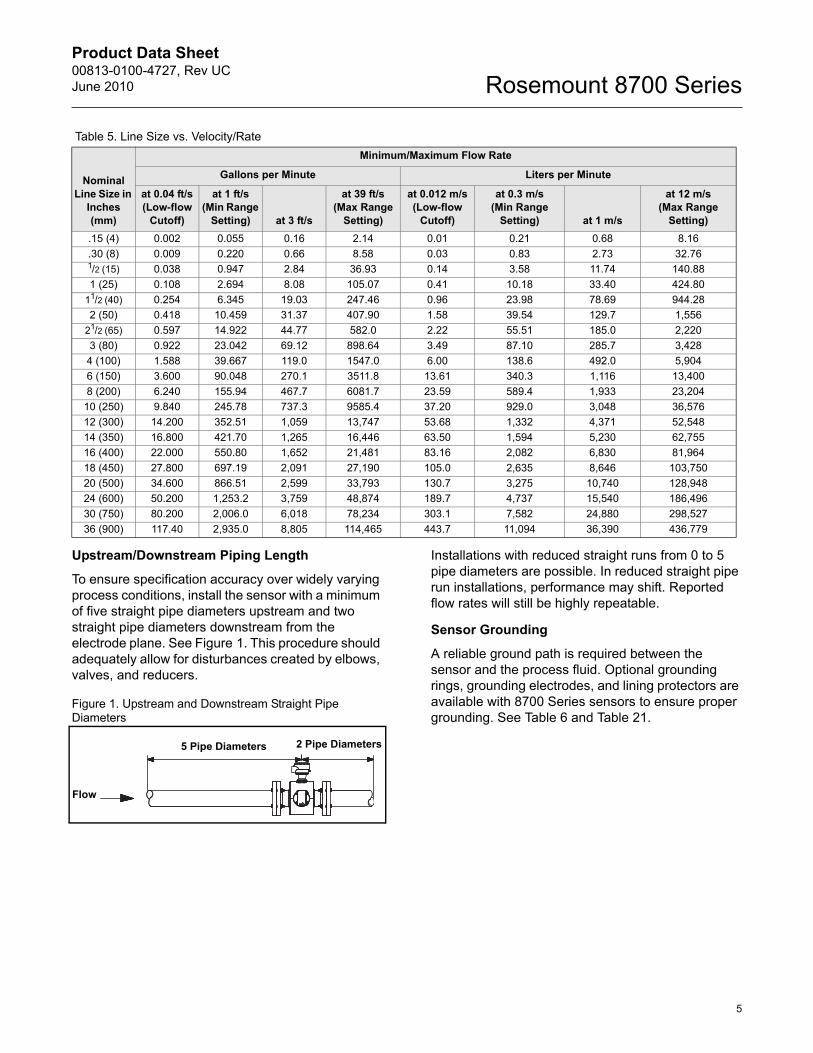
To ensure specification accuracy over widely varying process conditions, install the sensor with a minimum of five straight pipe diameters upstream and two straight pipe diameters downstream from the electrode plane. See Figure 1. This procedure should adequately allow for disturbances created by elbows, valves, and reducers.
Figure 1. Upstream and Downstream Straight Pipe Diameters
Installations with reduced straight runs from 0 to 5 pipe diameters are possible. In reduced straight pipe run installations, performance may shift. Reported flow rates will still be highly repeatable.
Sensor Grounding
A reliable ground path is required between the sensor and the process fluid. Optional grounding rings, grounding electrodes, and lining protectors are available with 8700 Series sensors to ensure proper grounding. See Table 6 and Table 21.
Table 5. Line Size vs. Velocity/Rate
Nominal Line Size in
Inches (mm)
Minimum/Maximum Flow Rate
Gallons per Minute Liters per Minute
at 0.04 ft/s(Low-flow
Cutoff)
at 1 ft/s(Min Range
Setting) at 3 ft/s
at 39 ft/s(Max Range
Setting)
at 0.012 m/s(Low-flow
Cutoff)
at 0.3 m/s(Min Range
Setting) at 1 m/s
at 12 m/s(Max Range
Setting).15 (4) 0.002 0.055 0.16 2.14 0.01 0.21 0.68 8.16.30 (8) 0.009 0.220 0.66 8.58 0.03 0.83 2.73 32.761/2 (15) 0.038 0.947 2.84 36.93 0.14 3.58 11.74 140.881 (25) 0.108 2.694 8.08 105.07 0.41 10.18 33.40 424.80
11/2 (40) 0.254 6.345 19.03 247.46 0.96 23.98 78.69 944.282 (50) 0.418 10.459 31.37 407.90 1.58 39.54 129.7 1,556
21/2 (65) 0.597 14.922 44.77 582.0 2.22 55.51 185.0 2,2203 (80) 0.922 23.042 69.12 898.64 3.49 87.10 285.7 3,428
4 (100) 1.588 39.667 119.0 1547.0 6.00 138.6 492.0 5,9046 (150) 3.600 90.048 270.1 3511.8 13.61 340.3 1,116 13,4008 (200) 6.240 155.94 467.7 6081.7 23.59 589.4 1,933 23,204
10 (250) 9.840 245.78 737.3 9585.4 37.20 929.0 3,048 36,57612 (300) 14.200 352.51 1,059 13,747 53.68 1,332 4,371 52,54814 (350) 16.800 421.70 1,265 16,446 63.50 1,594 5,230 62,75516 (400) 22.000 550.80 1,652 21,481 83.16 2,082 6,830 81,96418 (450) 27.800 697.19 2,091 27,190 105.0 2,635 8,646 103,75020 (500) 34.600 866.51 2,599 33,793 130.7 3,275 10,740 128,94824 (600) 50.200 1,253.2 3,759 48,874 189.7 4,737 15,540 186,49630 (750) 80.200 2,006.0 6,018 78,234 303.1 7,582 24,880 298,52736 (900) 117.40 2,935.0 8,805 114,465 443.7 11,094 36,390 436,779
Flow
5 Pipe Diameters 2 Pipe Diameters
Product Data Sheet00813-0100-4727, Rev UC
June 2010Rosemount 8700 Series
6
Ordering Information
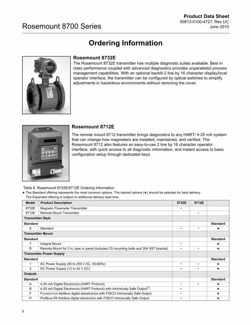
Rosemount 8732EThe Rosemount 8732E transmitter has multiple diagnostic suites available. Best in class performance coupled with advanced diagnostics provides unparalleled process management capabilities. With an optional backlit 2 line by 16 character display/local operator interface, the transmitter can be configured by optical switches to simplify adjustments in hazardous environments without removing the cover.
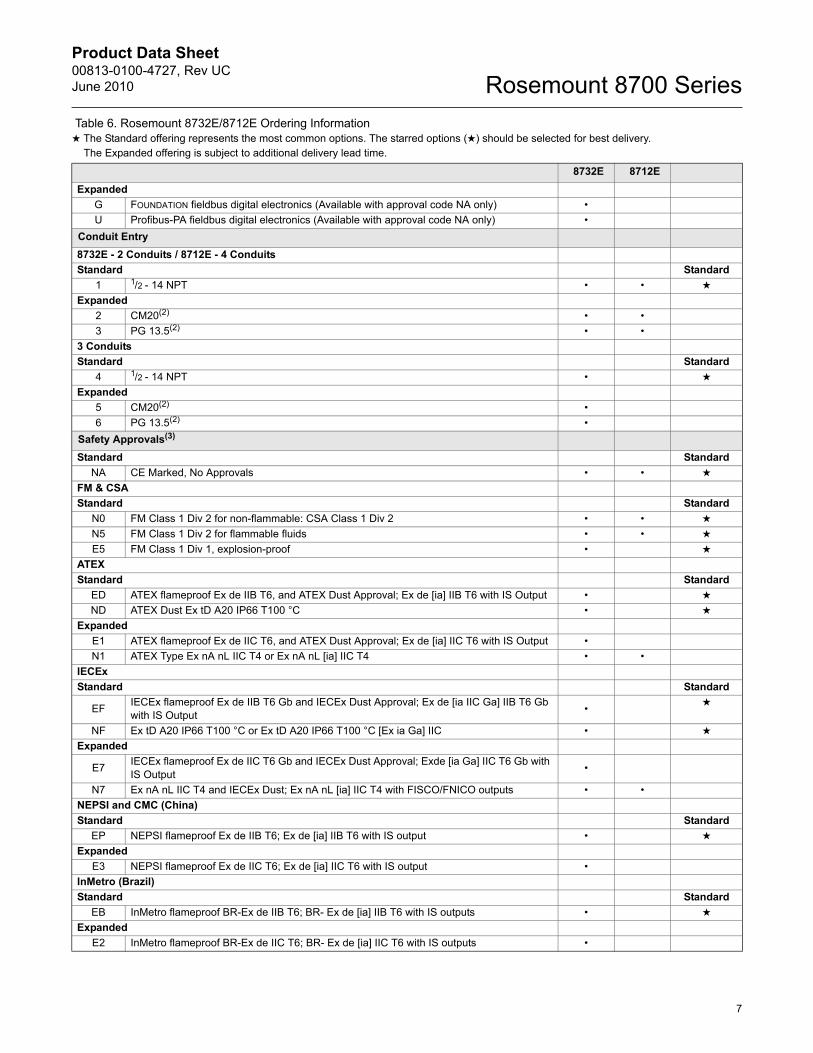
Rosemount 8712EThe remote mount 8712 transmitter brings diagnostics to any HART/ 4-20 mA system that can change how magmeters are installed, maintained, and verified. The Rosemount 8712 also features an easy-to-use 2 line by 16 character operator interface, with quick access to all diagnostic information, and instant access to basic configuration setup through dedicated keys.
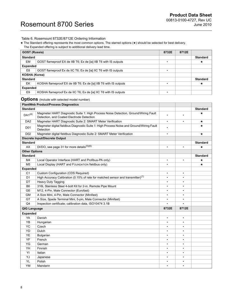
Table 6. Rosemount 8732E/8712E Ordering Information★ The Standard offering represents the most common options. The starred options (★) should be selected for best delivery.__The Expanded offering is subject to additional delivery lead time.
Model Product Description 8732E 8712E8732E Magnetic Flowmeter Transmitter •8712E Remote Mount Transmitter •
Transmitter StyleStandard Standard
S Standard • • ★
Transmitter MountStandard Standard
T Integral Mount • ★
R Remote Mount for 2 in. pipe or panel (includes CS mounting bolts and 304 SST bracket) • • ★
Transmitter Power SupplyStandard Standard
1 AC Power Supply (90 to 250 V AC, 50-60Hz) • • ★
2 DC Power Supply (12 to 42 V DC) • • ★
OutputsStandard Standard
A 4-20 mA Digital Electronics (HART Protocol) • • ★
B 4-20 mA Digital Electronics (HART Protocol) with Intrinsically Safe Output(1) • ★
F FOUNDATION fieldbus digital elecetronics with FISCO Intrinsically Safe Output • ★
P Profibus-PA fieldbus digital electronics with FISCO Intrinsically Safe Output • ★
Product Data Sheet00813-0100-4727, Rev UCJune 2010
7
Rosemount 8700 Series
8732E 8712EExpanded
G FOUNDATION fieldbus digital electronics (Available with approval code NA only) •U Profibus-PA fieldbus digital electronics (Available with approval code NA only) •
Conduit Entry8732E - 2 Conduits / 8712E - 4 ConduitsStandard Standard
1 1/2 - 14 NPT • • ★
Expanded2 CM20(2) • •3 PG 13.5(2) • •
3 ConduitsStandard Standard
4 1/2 - 14 NPT • ★
Expanded5 CM20(2) •6 PG 13.5(2) •
Safety Approvals(3)
Standard StandardNA CE Marked, No Approvals • • ★
FM & CSAStandard Standard
N0 FM Class 1 Div 2 for non-flammable: CSA Class 1 Div 2 • • ★
N5 FM Class 1 Div 2 for flammable fluids • • ★
E5 FM Class 1 Div 1, explosion-proof • ★
ATEXStandard Standard
ED ATEX flameproof Ex de IIB T6, and ATEX Dust Approval; Ex de [ia] IIB T6 with IS Output • ★
ND ATEX Dust Ex tD A20 IP66 T100 °C • ★
ExpandedE1 ATEX flameproof Ex de IIC T6, and ATEX Dust Approval; Ex de [ia] IIC T6 with IS Output •N1 ATEX Type Ex nA nL IIC T4 or Ex nA nL [ia] IIC T4 • •
IECExStandard Standard
EF IECEx flameproof Ex de IIB T6 Gb and IECEx Dust Approval; Ex de [ia IIC Ga] IIB T6 Gb with IS Output • ★
NF Ex tD A20 IP66 T100 °C or Ex tD A20 IP66 T100 °C [Ex ia Ga] IIC • ★
Expanded
E7 IECEx flameproof Ex de IIC T6 Gb and IECEx Dust Approval; Exde [ia Ga] IIC T6 Gb with IS Output •
N7 Ex nA nL IIC T4 and IECEx Dust; Ex nA nL [ia] IIC T4 with FISCO/FNICO outputs • •NEPSI and CMC (China)Standard Standard
EP NEPSI flameproof Ex de IIB T6; Ex de [ia] IIB T6 with IS output • ★
ExpandedE3 NEPSI flameproof Ex de IIC T6; Ex de [ia] IIC T6 with IS output •
InMetro (Brazil) Standard Standard
EB InMetro flameproof BR-Ex de IIB T6; BR- Ex de [ia] IIB T6 with IS outputs • ★
ExpandedE2 InMetro flameproof BR-Ex de IIC T6; BR- Ex de [ia] IIC T6 with IS outputs •
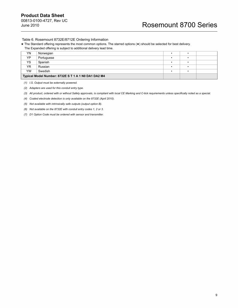
Table 6. Rosemount 8732E/8712E Ordering Information★ The Standard offering represents the most common options. The starred options (★) should be selected for best delivery.__The Expanded offering is subject to additional delivery lead time.
Product Data Sheet00813-0100-4727, Rev UC
June 2010Rosemount 8700 Series
8
GOST (Russia) 8732E 8712EStandard Standard
EM GOST flameproof EX de IIB T6; Ex de [ia] IIB T6 with IS outputs • ★
ExpandedE8 GOST flameproof Ex de IIC T6; Ex de [ia] IIC T6 with IS outputs •
KOSHA (Korea) Standard Standard
EK KOSHA flameproof EX de IIB T6; Ex de [ia] IIB T6 with IS outputs • ★
ExpandedE9 KOSHA flameproof Ex de IIC T6; Ex de [ia] IIC T6 with IS outputs •
Options (Include with selected model number)PlantWeb Product/Process DiagnosticsStandard Standard
DA1(4) Magmeter HART Diagnostic Suite 1: High Process Noise Detection, Ground/Wiring Fault Detection, and Coated Electrode Detection • • ★
DA2 Magmeter HART Diagnostic Suite 2: SMART Meter Verification • • ★
D01 Magmeter digital fieldbus Diagnostic Suite 1: High Process Noise and Ground/Wiring Fault Detection • ★
D02 Magmeter digital fieldbus Diagnostic Suite 2: SMART Meter Verification • ★
Discrete Input/Discrete OutputStandard Standard
AX DI/DO, see page 31 for more details(5)(6) • • ★
Other OptionsStandard Standard
M4 Local Operator Interface (HART and Profibus-PA only) • • ★
M5 Local Display (HART and FOUNDATION fieldbus only) • ★
ExpandedC1 Custom Configuration (CDS Required) • •D1 High Accuracy Calibration (0.15% of rate for matched sensor and transmitter)(7) • •DT Heavy Duty Tagging • •B6 316L Stainless Steel 4-bolt Kit for 2-in. Remote Pipe Mount • •GE M12, 4-Pin, Male Connector (Eurofast) • •GM A Size Mini, 4-Pin, Male Connector (Minifast) • •GT A Size, Spade Terminal Mini, 5-pin, Male Connector (Minifast) • •Q4 Inspection certificate; calibration data, ISO10474 3.1B • •
QIG Language 8732E 8712EExpanded
YA Danish • •YB Hungarian • •YC Czech • •YD Dutch • •YE Bulgarian • •YF French • •YG German • •YH Finnish • •YI Italian • •YJ Japanese • •YL Polish • •YM Mandarin • •
Table 6. Rosemount 8732E/8712E Ordering Information★ The Standard offering represents the most common options. The starred options (★) should be selected for best delivery.__The Expanded offering is subject to additional delivery lead time.
Product Data Sheet00813-0100-4727, Rev UCJune 2010
9
Rosemount 8700 Series
YN Norwegian • •YP Portuguese • •YS Spanish • •YR Russian • •YW Swedish • •
Typical Model Number: 8732E S T 1 A 1 N0 DA1 DA2 M4
(1) I.S. Output must be externally powered.
(2) Adapters are used for this conduit entry type.
(3) All product, ordered with or without Safety approvals, is compliant with local CE Marking and C-tick requirements unless specifically noted as a special.
(4) Coated electrode detection is only available on the 8732E (April 2010).
(5) Not available with intrinsically safe outputs (output option B).
(6) Not available on the 8732E with conduit entry codes 1, 2 or 3.
(7) D1 Option Code must be ordered with sensor and transmitter.
Table 6. Rosemount 8732E/8712E Ordering Information★ The Standard offering represents the most common options. The starred options (★) should be selected for best delivery.__The Expanded offering is subject to additional delivery lead time.
Product Data Sheet00813-0100-4727, Rev UC
June 2010Rosemount 8700 Series
10
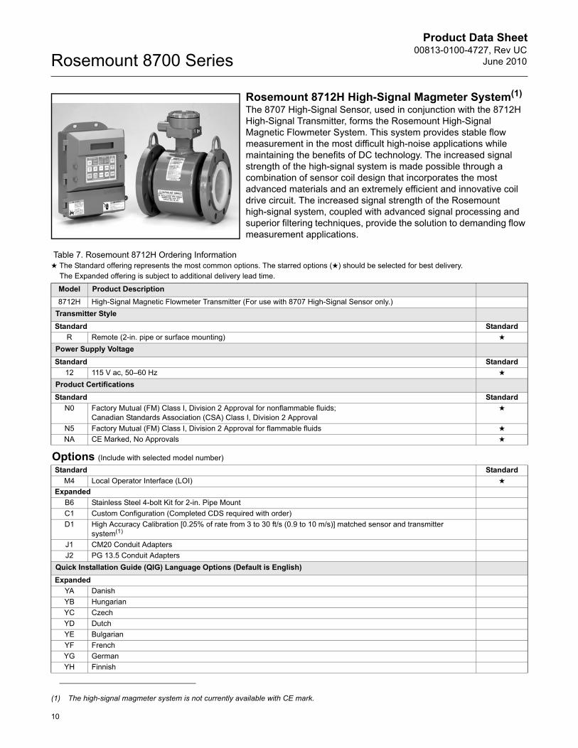
Rosemount 8712H High-Signal Magmeter System(1)
The 8707 High-Signal Sensor, used in conjunction with the 8712H High-Signal Transmitter, forms the Rosemount High-Signal Magnetic Flowmeter System. This system provides stable flow measurement in the most difficult high-noise applications while maintaining the benefits of DC technology. The increased signal strength of the high-signal system is made possible through a combination of sensor coil design that incorporates the most advanced materials and an extremely efficient and innovative coil drive circuit. The increased signal strength of the Rosemount high-signal system, coupled with advanced signal processing and superior filtering techniques, provide the solution to demanding flow measurement applications.
(1) The high-signal magmeter system is not currently available with CE mark.
Table 7. Rosemount 8712H Ordering Information★ The Standard offering represents the most common options. The starred options (★) should be selected for best delivery.__The Expanded offering is subject to additional delivery lead time.
Model Product Description8712H High-Signal Magnetic Flowmeter Transmitter (For use with 8707 High-Signal Sensor only.)
Transmitter StyleStandard Standard
R Remote (2-in. pipe or surface mounting) ★
Power Supply VoltageStandard Standard
12 115 V ac, 50–60 Hz ★
Product CertificationsStandard Standard
N0 Factory Mutual (FM) Class I, Division 2 Approval for nonflammable fluids;Canadian Standards Association (CSA) Class I, Division 2 Approval
★
N5 Factory Mutual (FM) Class I, Division 2 Approval for flammable fluids ★
NA CE Marked, No Approvals ★
Options (Include with selected model number)Standard Standard
M4 Local Operator Interface (LOI) ★
ExpandedB6 Stainless Steel 4-bolt Kit for 2-in. Pipe MountC1 Custom Configuration (Completed CDS required with order)D1 High Accuracy Calibration [0.25% of rate from 3 to 30 ft/s (0.9 to 10 m/s)] matched sensor and transmitter
system(1)
J1 CM20 Conduit AdaptersJ2 PG 13.5 Conduit Adapters
Quick Installation Guide (QIG) Language Options (Default is English)Expanded
YA DanishYB HungarianYC CzechYD DutchYE BulgarianYF FrenchYG GermanYH Finnish
Product Data Sheet00813-0100-4727, Rev UCJune 2010
11
Rosemount 8700 Series
YI ItalianYJ JapaneseYL PolishYM MandarinYN NorwegianYP PortugueseYS SpanishYR RussianYW Swedish
Typical Model Number: 8712H R 12 N 0 M 4
(1) D1 Option Code must be selected for both sensor and transmitter.
Table 7. Rosemount 8712H Ordering Information★ The Standard offering represents the most common options. The starred options (★) should be selected for best delivery.__The Expanded offering is subject to additional delivery lead time.
Product Data Sheet00813-0100-4727, Rev UC
June 2010Rosemount 8700 Series
12
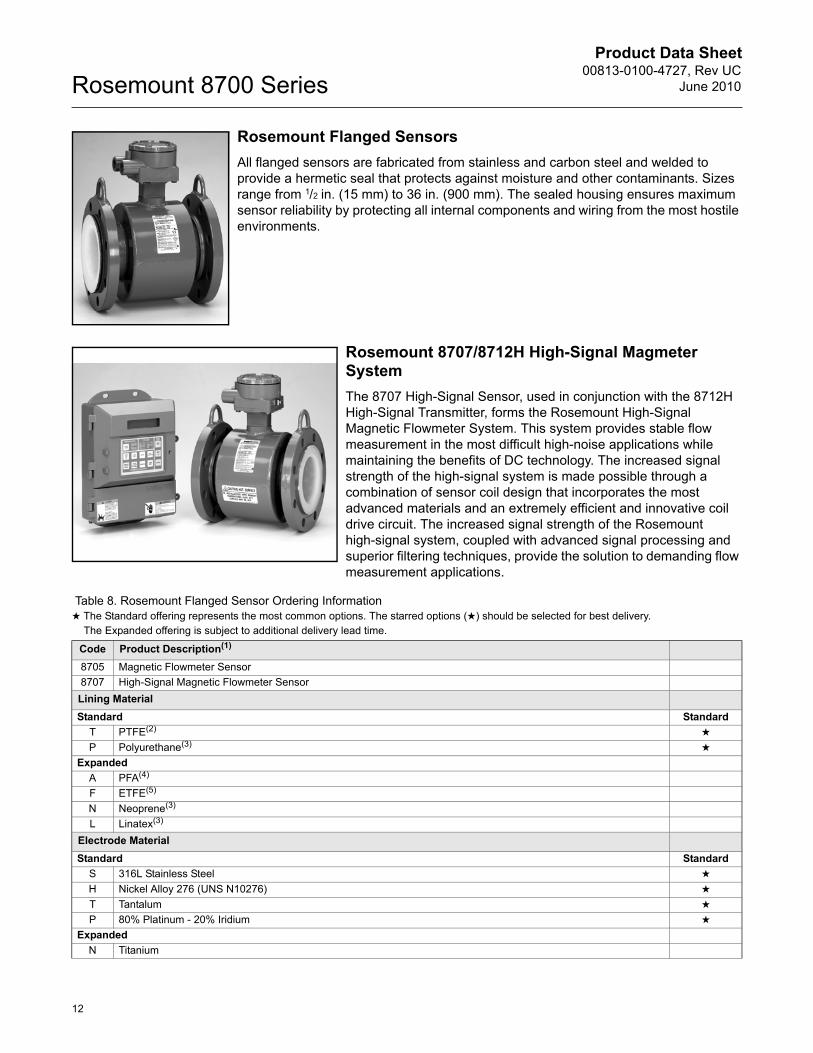
Rosemount Flanged SensorsAll flanged sensors are fabricated from stainless and carbon steel and welded to provide a hermetic seal that protects against moisture and other contaminants. Sizes range from 1/2 in. (15 mm) to 36 in. (900 mm). The sealed housing ensures maximum sensor reliability by protecting all internal components and wiring from the most hostile environments.
Rosemount 8707/8712H High-Signal Magmeter System The 8707 High-Signal Sensor, used in conjunction with the 8712H High-Signal Transmitter, forms the Rosemount High-Signal Magnetic Flowmeter System. This system provides stable flow measurement in the most difficult high-noise applications while maintaining the benefits of DC technology. The increased signal strength of the high-signal system is made possible through a combination of sensor coil design that incorporates the most advanced materials and an extremely efficient and innovative coil drive circuit. The increased signal strength of the Rosemount high-signal system, coupled with advanced signal processing and superior filtering techniques, provide the solution to demanding flow measurement applications.
Table 8. Rosemount Flanged Sensor Ordering Information★ The Standard offering represents the most common options. The starred options (★) should be selected for best delivery.__The Expanded offering is subject to additional delivery lead time.
Code Product Description(1)
8705 Magnetic Flowmeter Sensor8707 High-Signal Magnetic Flowmeter SensorLining MaterialStandard Standard
T PTFE(2) ★
P Polyurethane(3) ★
ExpandedA PFA(4)
F ETFE(5)
N Neoprene(3)
L Linatex(3)
Electrode MaterialStandard Standard
S 316L Stainless Steel ★
H Nickel Alloy 276 (UNS N10276) ★
T Tantalum ★
P 80% Platinum - 20% Iridium ★
ExpandedN Titanium
Product Data Sheet00813-0100-4727, Rev UCJune 2010
13
Rosemount 8700 Series
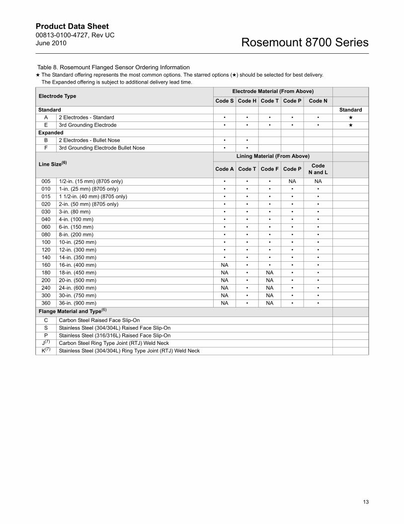
Electrode TypeElectrode Material (From Above)
Code S Code H Code T Code P Code NStandard Standard
A 2 Electrodes - Standard • • • • • ★
E 3rd Grounding Electrode • • • • • ★
ExpandedB 2 Electrodes - Bullet Nose • •F 3rd Grounding Electrode Bullet Nose • •
Line Size(6)Lining Material (From Above)
Code A Code T Code F Code P Code N and L
005 1/2-in. (15 mm) (8705 only) • • • NA NA010 1-in. (25 mm) (8705 only) • • • • •015 1 1/2-in. (40 mm) (8705 only) • • • • •020 2-in. (50 mm) (8705 only) • • • • •030 3-in. (80 mm) • • • • •040 4-in. (100 mm) • • • • •060 6-in. (150 mm) • • • • •080 8-in. (200 mm) • • • • •100 10-in. (250 mm) • • • • •120 12-in. (300 mm) • • • • •140 14-in. (350 mm) • • • • •160 16-in. (400 mm) NA • • • •180 18-in. (450 mm) NA • NA • •200 20-in. (500 mm) NA • NA • •240 24-in. (600 mm) NA • NA • •300 30-in. (750 mm) NA • NA • •360 36-in. (900 mm) NA • NA • •
Flange Material and Type(6)
C Carbon Steel Raised Face Slip-OnS Stainless Steel (304/304L) Raised Face Slip-OnP Stainless Steel (316/316L) Raised Face Slip-On
J(7) Carbon Steel Ring Type Joint (RTJ) Weld NeckK(7) Stainless Steel (304/304L) Ring Type Joint (RTJ) Weld Neck
Table 8. Rosemount Flanged Sensor Ordering Information★ The Standard offering represents the most common options. The starred options (★) should be selected for best delivery.__The Expanded offering is subject to additional delivery lead time.
Product Data Sheet00813-0100-4727, Rev UC
June 2010Rosemount 8700 Series
14
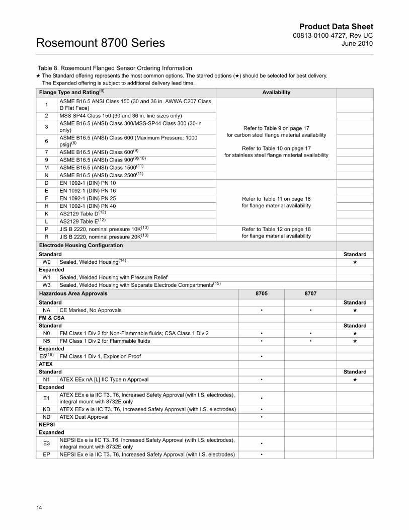
Flange Type and Rating(6) Availability
1 ASME B16.5 ANSI Class 150 (30 and 36 in. AWWA C207 Class D Flat Face)
Refer to Table 9 on page 17 for carbon steel flange material availability
Refer to Table 10 on page 17for stainless steel flange material availability
2 MSS SP44 Class 150 (30 and 36 in. line sizes only)
3 ASME B16.5 (ANSI) Class 300/MSS-SP44 Class 300 (30-in only)
6 ASME B16.5 (ANSI) Class 600 (Maximum Pressure: 1000 psig)(8)
7 ASME B16.5 (ANSI) Class 600(9)
9 ASME B16.5 (ANSI) Class 900(9)(10)
M ASME B16.5 (ANSI) Class 1500(11)
N ASME B16.5 (ANSI) Class 2500(11)
D EN 1092-1 (DIN) PN 10
Refer to Table 11 on page 18for flange material availability
E EN 1092-1 (DIN) PN 16F EN 1092-1 (DIN) PN 25H EN 1092-1 (DIN) PN 40K AS2129 Table D(12)
L AS2129 Table E(12)
P JIS B 2220, nominal pressure 10K(13) Refer to Table 12 on page 18for flange material availabilityR JIS B 2220, nominal pressure 20K(13)
Electrode Housing ConfigurationStandard Standard
W0 Sealed, Welded Housing(14) ★
ExpandedW1 Sealed, Welded Housing with Pressure ReliefW3 Sealed, Welded Housing with Separate Electrode Compartments(15)
Hazardous Area Approvals 8705 8707Standard Standard
NA CE Marked, No Approvals • • ★
FM & CSAStandard Standard
N0 FM Class 1 Div 2 for Non-Flammable fluids; CSA Class 1 Div 2 • • ★
N5 FM Class 1 Div 2 for Flammable fluids • • ★
ExpandedE5(16) FM Class 1 Div 1, Explosion Proof •ATEX Standard Standard
N1 ATEX EEx nA [L] IIC Type n Approval • ★
Expanded
E1 ATEX EEx e ia IIC T3..T6, Increased Safety Approval (with I.S. electrodes), integral mount with 8732E only •
KD ATEX EEx e ia IIC T3..T6, Increased Safety Approval (with I.S. electrodes) •ND ATEX Dust Approval •
NEPSI Expanded
E3 NEPSI Ex e ia IIC T3..T6, Increased Safety Approval (with I.S. electrodes), integral mount with 8732E only •
EP NEPSI Ex e ia IIC T3..T6, Increased Safety Approval (with I.S. electrodes) •
Table 8. Rosemount Flanged Sensor Ordering Information★ The Standard offering represents the most common options. The starred options (★) should be selected for best delivery.__The Expanded offering is subject to additional delivery lead time.
Product Data Sheet00813-0100-4727, Rev UCJune 2010
15
Rosemount 8700 Series
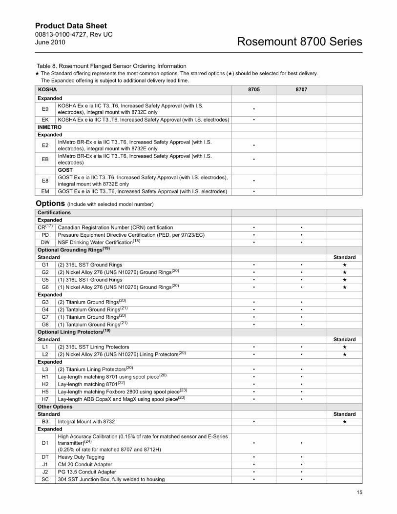
KOSHA 8705 8707Expanded
E9 KOSHA Ex e ia IIC T3..T6, Increased Safety Approval (with I.S. electrodes), integral mount with 8732E only •
EK KOSHA Ex e ia IIC T3..T6, Increased Safety Approval (with I.S. electrodes) •INMETRO Expanded
E2 InMetro BR-Ex e ia IIC T3..T6, Increased Safety Approval (with I.S. electrodes), integral mount with 8732E only •
EB InMetro BR-Ex e ia IIC T3..T6, Increased Safety Approval (with I.S. electrodes) •
GOST
E8 GOST Ex e ia IIC T3..T6, Increased Safety Approval (with I.S. electrodes), integral mount with 8732E only •
EM GOST Ex e ia IIC T3..T6, Increased Safety Approval (with I.S. electrodes) •
Options (Include with selected model number)CertificationsExpandedCR(17) Canadian Registration Number (CRN) certification • •
PD Pressure Equipment Directive Certification (PED, per 97/23/EC) • •DW NSF Drinking Water Certification(18) • •
Optional Grounding Rings(19)
Standard StandardG1 (2) 316L SST Ground Rings • • ★
G2 (2) Nickel Alloy 276 (UNS N10276) Ground Rings(20) • • ★
G5 (1) 316L SST Ground Rings • • ★
G6 (1) Nickel Alloy 276 (UNS N10276) Ground Rings(20) • • ★
ExpandedG3 (2) Titanium Ground Rings(20) • •G4 (2) Tantalum Ground Rings(21) • •G7 (1) Titanium Ground Rings(20) • •G8 (1) Tantalum Ground Rings(21) • •
Optional Lining Protectors(19)
Standard StandardL1 (2) 316L SST Lining Protectors • • ★
L2 (2) Nickel Alloy 276 (UNS N10276) Lining Protectors(20) • • ★
ExpandedL3 (2) Titanium Lining Protectors(20) • •H1 Lay-length matching 8701 using spool piece(20) • •H2 Lay-length matching 8701(22) • •H5 Lay-length matching Foxboro 2800 using spool piece(23) • •H7 Lay-length ABB CopaX and MagX using spool piece(20) • •
Other OptionsStandard Standard
B3 Integral Mount with 8732 • ★
Expanded
D1High Accuracy Calibration (0.15% of rate for matched sensor and E-Series transmitter)(24) (0.25% of rate for matched 8707 and 8712H)
• •
DT Heavy Duty Tagging • •J1 CM 20 Conduit Adapter • •J2 PG 13.5 Conduit Adapter • •SC 304 SST Junction Box, fully welded to housing • •
Table 8. Rosemount Flanged Sensor Ordering Information★ The Standard offering represents the most common options. The starred options (★) should be selected for best delivery.__The Expanded offering is subject to additional delivery lead time.
Product Data Sheet00813-0100-4727, Rev UC
June 2010Rosemount 8700 Series
16
8705 8707
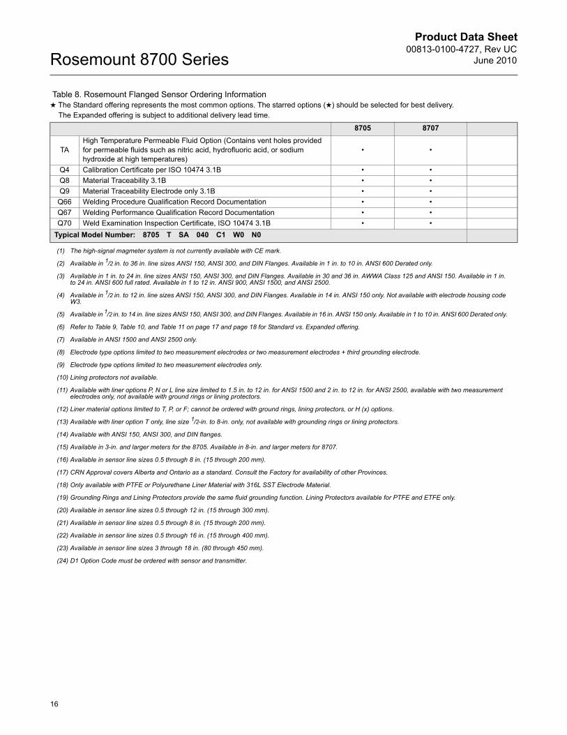
TAHigh Temperature Permeable Fluid Option (Contains vent holes provided for permeable fluids such as nitric acid, hydrofluoric acid, or sodium hydroxide at high temperatures)
• •
Q4 Calibration Certificate per ISO 10474 3.1B • •Q8 Material Traceability 3.1B • •Q9 Material Traceability Electrode only 3.1B • •
Q66 Welding Procedure Qualification Record Documentation • •Q67 Welding Performance Qualification Record Documentation • •Q70 Weld Examination Inspection Certificate, ISO 10474 3.1B • •
Typical Model Number: 8705 T SA 040 C1 W0 N0
(1) The high-signal magmeter system is not currently available with CE mark.
(2) Available in 1/2 in. to 36 in. line sizes ANSI 150, ANSI 300, and DIN Flanges. Available in 1 in. to 10 in. ANSI 600 Derated only.
(3) Available in 1 in. to 24 in. line sizes ANSI 150, ANSI 300, and DIN Flanges. Available in 30 and 36 in. AWWA Class 125 and ANSI 150. Available in 1 in. to 24 in. ANSI 600 full rated. Available in 1 to 12 in. ANSI 900, ANSI 1500, and ANSI 2500.
(4) Available in 1/2 in. to 12 in. line sizes ANSI 150, ANSI 300, and DIN Flanges. Available in 14 in. ANSI 150 only. Not available with electrode housing code W3.
(5) Available in 1/2 in. to 14 in. line sizes ANSI 150, ANSI 300, and DIN Flanges. Available in 16 in. ANSI 150 only. Available in 1 to 10 in. ANSI 600 Derated only.
(6) Refer to Table 9, Table 10, and Table 11 on page 17 and page 18 for Standard vs. Expanded offering.
(7) Available in ANSI 1500 and ANSI 2500 only.
(8) Electrode type options limited to two measurement electrodes or two measurement electrodes + third grounding electrode.
(9) Electrode type options limited to two measurement electrodes only.
(10) Lining protectors not available.
(11) Available with liner options P, N or L line size limited to 1.5 in. to 12 in. for ANSI 1500 and 2 in. to 12 in. for ANSI 2500, available with two measurement electrodes only, not available with ground rings or lining protectors.
(12) Liner material options limited to T, P, or F; cannot be ordered with ground rings, lining protectors, or H (x) options.
(13) Available with liner option T only, line size 1/2-in. to 8-in. only, not available with grounding rings or lining protectors.
(14) Available with ANSI 150, ANSI 300, and DIN flanges.
(15) Available in 3-in. and larger meters for the 8705. Available in 8-in. and larger meters for 8707.
(16) Available in sensor line sizes 0.5 through 8 in. (15 through 200 mm).
(17) CRN Approval covers Alberta and Ontario as a standard. Consult the Factory for availability of other Provinces.
(18) Only available with PTFE or Polyurethane Liner Material with 316L SST Electrode Material.
(19) Grounding Rings and Lining Protectors provide the same fluid grounding function. Lining Protectors available for PTFE and ETFE only.
(20) Available in sensor line sizes 0.5 through 12 in. (15 through 300 mm).
(21) Available in sensor line sizes 0.5 through 8 in. (15 through 200 mm).
(22) Available in sensor line sizes 0.5 through 16 in. (15 through 400 mm).
(23) Available in sensor line sizes 3 through 18 in. (80 through 450 mm).
(24) D1 Option Code must be ordered with sensor and transmitter.
Table 8. Rosemount Flanged Sensor Ordering Information★ The Standard offering represents the most common options. The starred options (★) should be selected for best delivery.__The Expanded offering is subject to additional delivery lead time.
Product Data Sheet00813-0100-4727, Rev UCJune 2010
17
Rosemount 8700 Series
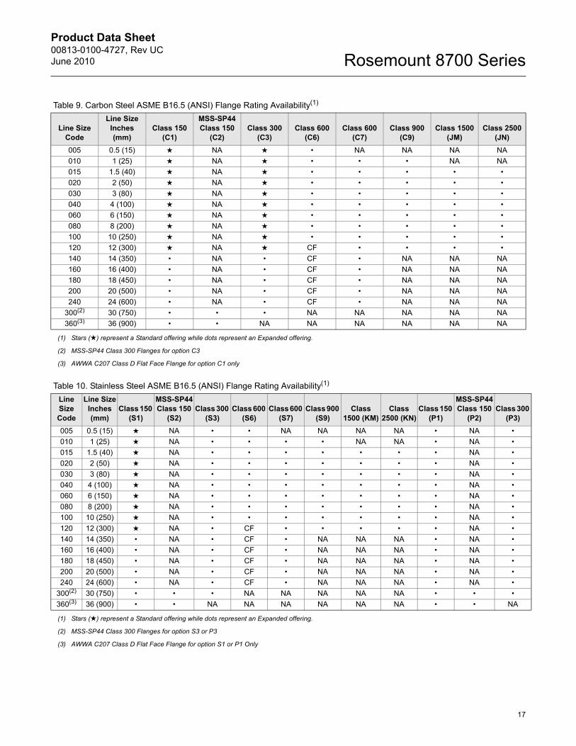
Table 9. Carbon Steel ASME B16.5 (ANSI) Flange Rating Availability(1)
Line Size Code
Line SizeInches(mm)
Class 150 (C1)
MSS-SP44Class 150
(C2)Class 300
(C3)Class 600
(C6)Class 600
(C7)Class 900
(C9)Class 1500
(JM)Class 2500
(JN)005 0.5 (15) ★ NA ★ • NA NA NA NA010 1 (25) ★ NA ★ • • • NA NA015 1.5 (40) ★ NA ★ • • • • •020 2 (50) ★ NA ★ • • • • •030 3 (80) ★ NA ★ • • • • •040 4 (100) ★ NA ★ • • • • •060 6 (150) ★ NA ★ • • • • •080 8 (200) ★ NA ★ • • • • •100 10 (250) ★ NA ★ • • • • •120 12 (300) ★ NA ★ CF • • • •140 14 (350) • NA • CF • NA NA NA160 16 (400) • NA • CF • NA NA NA180 18 (450) • NA • CF • NA NA NA200 20 (500) • NA • CF • NA NA NA240 24 (600) • NA • CF • NA NA NA
300(2) 30 (750) • • • NA NA NA NA NA360(3) 36 (900) • • NA NA NA NA NA NA
(1) Stars (★) represent a Standard offering while dots represent an Expanded offering.
(2) MSS-SP44 Class 300 Flanges for option C3
(3) AWWA C207 Class D Flat Face Flange for option C1 only
Table 10. Stainless Steel ASME B16.5 (ANSI) Flange Rating Availability(1)
Line Size Code
Line SizeInches(mm)
Class 150 (S1)
MSS-SP44Class 150
(S2)Class 300
(S3)Class 600
(S6)Class 600
(S7)Class 900
(S9)Class
1500 (KM)Class
2500 (KN)Class 150
(P1)
MSS-SP44 Class 150
(P2)Class 300
(P3)005 0.5 (15) ★ NA • • NA NA NA NA • NA •010 1 (25) ★ NA • • • • NA NA • NA •015 1.5 (40) ★ NA • • • • • • • NA •020 2 (50) ★ NA • • • • • • • NA •030 3 (80) ★ NA • • • • • • • NA •040 4 (100) ★ NA • • • • • • • NA •060 6 (150) ★ NA • • • • • • • NA •080 8 (200) ★ NA • • • • • • • NA •100 10 (250) ★ NA • • • • • • • NA •120 12 (300) ★ NA • CF • • • • • NA •140 14 (350) • NA • CF • NA NA NA • NA •160 16 (400) • NA • CF • NA NA NA • NA •180 18 (450) • NA • CF • NA NA NA • NA •200 20 (500) • NA • CF • NA NA NA • NA •240 24 (600) • NA • CF • NA NA NA • NA •
300(2) 30 (750) • • • NA NA NA NA NA • • •360(3) 36 (900) • • NA NA NA NA NA NA • • NA
(1) Stars (★) represent a Standard offering while dots represent an Expanded offering.
(2) MSS-SP44 Class 300 Flanges for option S3 or P3
(3) AWWA C207 Class D Flat Face Flange for option S1 or P1 Only
Product Data Sheet00813-0100-4727, Rev UC
June 2010Rosemount 8700 Series
18
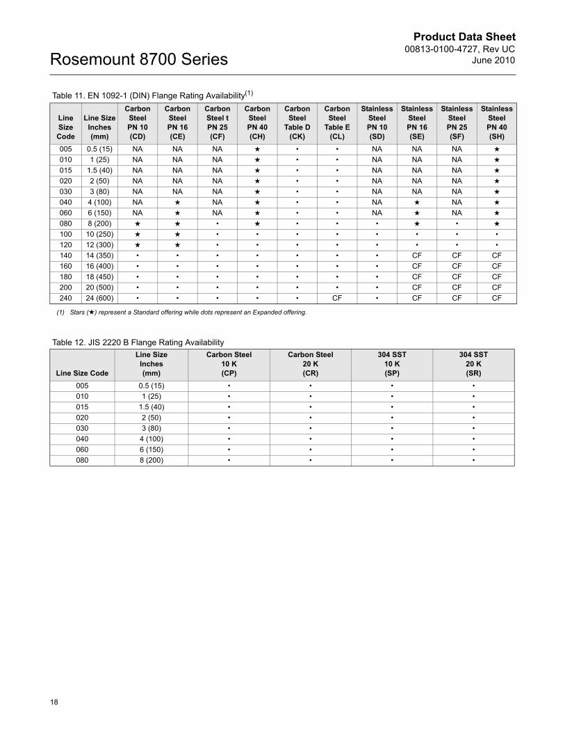
Table 12. JIS 2220 B Flange Rating Availability
Table 11. EN 1092-1 (DIN) Flange Rating Availability(1)
Line Size Code
Line SizeInches(mm)
Carbon Steel PN 10 (CD)
Carbon Steel PN 16 (CE)
Carbon Steel tPN 25 (CF)
Carbon Steel PN 40 (CH)
Carbon Steel
Table D(CK)
Carbon Steel
Table E(CL)
Stainless Steel PN 10 (SD)
Stainless Steel PN 16 (SE)
Stainless Steel PN 25 (SF)
Stainless Steel PN 40 (SH)
005 0.5 (15) NA NA NA ★ • • NA NA NA ★
010 1 (25) NA NA NA ★ • • NA NA NA ★
015 1.5 (40) NA NA NA ★ • • NA NA NA ★
020 2 (50) NA NA NA ★ • • NA NA NA ★
030 3 (80) NA NA NA ★ • • NA NA NA ★
040 4 (100) NA ★ NA ★ • • NA ★ NA ★
060 6 (150) NA ★ NA ★ • • NA ★ NA ★
080 8 (200) ★ ★ • ★ • • • ★ • ★
100 10 (250) ★ ★ • • • • • • • •120 12 (300) ★ ★ • • • • • • • •140 14 (350) • • • • • • • CF CF CF160 16 (400) • • • • • • • CF CF CF180 18 (450) • • • • • • • CF CF CF200 20 (500) • • • • • • • CF CF CF240 24 (600) • • • • • CF • CF CF CF
(1) Stars (★) represent a Standard offering while dots represent an Expanded offering.
Line Size Code
Line SizeInches(mm)
Carbon Steel 10 K(CP)
Carbon Steel 20 K(CR)
304 SST10 K(SP)
304 SST20 K(SR)
005 0.5 (15) • • • •010 1 (25) • • • •015 1.5 (40) • • • •020 2 (50) • • • •030 3 (80) • • • •040 4 (100) • • • •060 6 (150) • • • •080 8 (200) • • • •
Product Data Sheet00813-0100-4727, Rev UCJune 2010
19
Rosemount 8700 Series
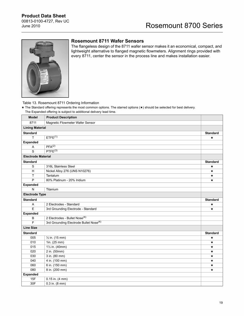
Rosemount 8711 Wafer SensorsThe flangeless design of the 8711 wafer sensor makes it an economical, compact, and lightweight alternative to flanged magnetic flowmeters. Alignment rings provided with every 8711, center the sensor in the process line and makes installation easier.
Table 13. Rosemount 8711 Ordering Information★ The Standard offering represents the most common options. The starred options (★) should be selected for best delivery.__The Expanded offering is subject to additional delivery lead time.
Model Product Description8711 Magnetic Flowmeter Wafer Sensor
Lining MaterialStandard Standard
T ETFE(1) ★
ExpandedA PFA(2)
S PTFE(3)
Electrode MaterialStandard Standard
S 316L Stainless Steel ★
H Nickel Alloy 276 (UNS N10276) ★
T Tantalum ★
P 80% Platinum - 20% Iridium ★
ExpandedN Titanium
Electrode TypeStandard Standard
A 2 Electrodes - Standard ★
E 3rd Grounding Electrode - Standard ★
ExpandedB 2 Electrodes - Bullet Nose(4)
F 3rd Grounding Electrode Bullet Nose(4)
Line SizeStandard Standard
005 ½ in. (15 mm) ★
010 1in. (25 mm) ★
015 1½ in. (40mm) ★
020 2 in. (50mm) ★
030 3 in. (80 mm) ★
040 4 in. (100 mm) ★
060 6 in. (150 mm) ★
080 8 in. (200 mm) ★
Expanded15F 0.15 in. (4 mm)30F 0.3 in. (8 mm)
Product Data Sheet00813-0100-4727, Rev UC
June 2010Rosemount 8700 Series
20
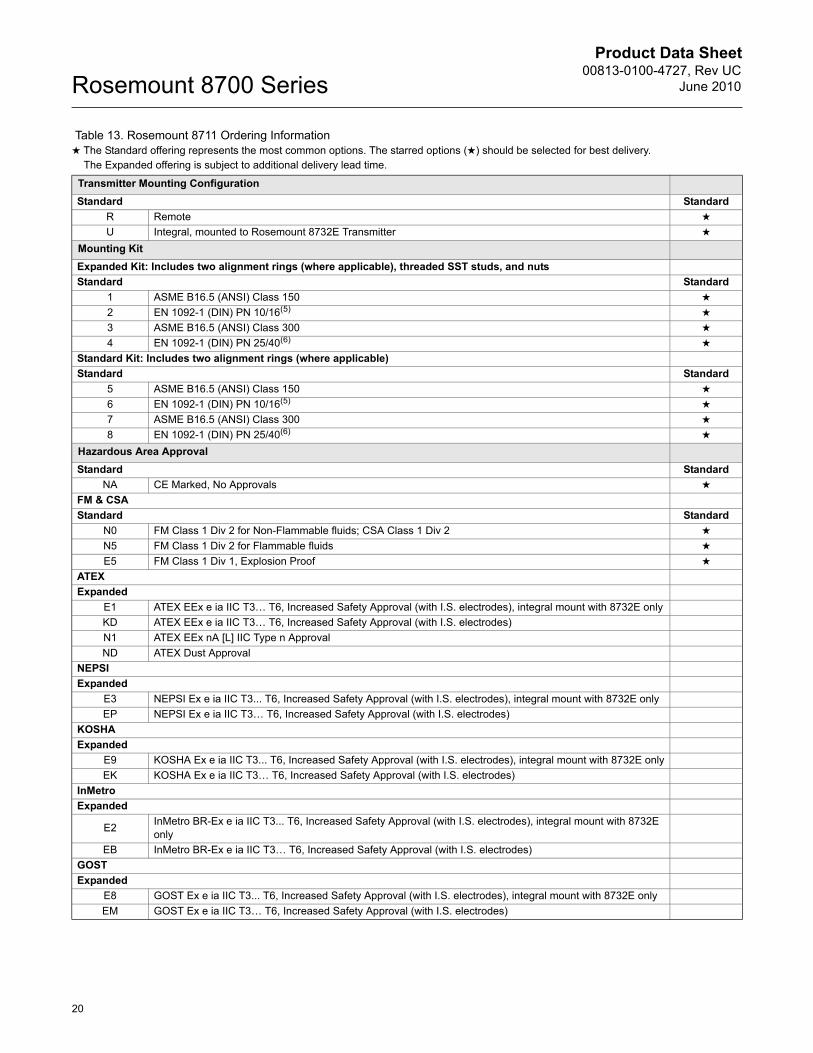
Transmitter Mounting ConfigurationStandard Standard
R Remote ★
U Integral, mounted to Rosemount 8732E Transmitter ★
Mounting KitExpanded Kit: Includes two alignment rings (where applicable), threaded SST studs, and nutsStandard Standard
1 ASME B16.5 (ANSI) Class 150 ★
2 EN 1092-1 (DIN) PN 10/16(5) ★
3 ASME B16.5 (ANSI) Class 300 ★
4 EN 1092-1 (DIN) PN 25/40(6) ★
Standard Kit: Includes two alignment rings (where applicable)Standard Standard
5 ASME B16.5 (ANSI) Class 150 ★
6 EN 1092-1 (DIN) PN 10/16(5) ★
7 ASME B16.5 (ANSI) Class 300 ★
8 EN 1092-1 (DIN) PN 25/40(6) ★
Hazardous Area ApprovalStandard Standard
NA CE Marked, No Approvals ★
FM & CSAStandard Standard
N0 FM Class 1 Div 2 for Non-Flammable fluids; CSA Class 1 Div 2 ★
N5 FM Class 1 Div 2 for Flammable fluids ★
E5 FM Class 1 Div 1, Explosion Proof ★
ATEXExpanded
E1 ATEX EEx e ia IIC T3… T6, Increased Safety Approval (with I.S. electrodes), integral mount with 8732E onlyKD ATEX EEx e ia IIC T3… T6, Increased Safety Approval (with I.S. electrodes)N1 ATEX EEx nA [L] IIC Type n ApprovalND ATEX Dust Approval
NEPSIExpanded
E3 NEPSI Ex e ia IIC T3... T6, Increased Safety Approval (with I.S. electrodes), integral mount with 8732E onlyEP NEPSI Ex e ia IIC T3… T6, Increased Safety Approval (with I.S. electrodes)
KOSHAExpanded
E9 KOSHA Ex e ia IIC T3... T6, Increased Safety Approval (with I.S. electrodes), integral mount with 8732E onlyEK KOSHA Ex e ia IIC T3… T6, Increased Safety Approval (with I.S. electrodes)
InMetroExpanded
E2 InMetro BR-Ex e ia IIC T3... T6, Increased Safety Approval (with I.S. electrodes), integral mount with 8732E only
EB InMetro BR-Ex e ia IIC T3… T6, Increased Safety Approval (with I.S. electrodes)GOSTExpanded
E8 GOST Ex e ia IIC T3... T6, Increased Safety Approval (with I.S. electrodes), integral mount with 8732E onlyEM GOST Ex e ia IIC T3… T6, Increased Safety Approval (with I.S. electrodes)
Table 13. Rosemount 8711 Ordering Information★ The Standard offering represents the most common options. The starred options (★) should be selected for best delivery.__The Expanded offering is subject to additional delivery lead time.
Product Data Sheet00813-0100-4727, Rev UCJune 2010
21
Rosemount 8700 Series
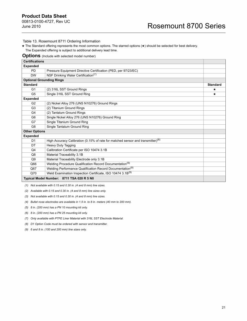
Options (Include with selected model number)CertificationsExpanded
PD Pressure Equipment Directive Certification (PED, per 97/23/EC)DW NSF Drinking Water Certification(7)
Optional Grounding RingsStandard Standard
G1 (2) 316L SST Ground Rings ★
G5 Single 316L SST Ground Ring ★
ExpandedG2 (2) Nickel Alloy 276 (UNS N10276) Ground RingsG3 (2) Titanium Ground RingsG4 (2) Tantalum Ground RingsG6 Single Nickel Alloy 276 (UNS N10276) Ground RingG7 Single Titanium Ground RingG8 Single Tantalum Ground Ring
Other OptionsExpanded
D1 High Accuracy Calibration (0.15% of rate for matched sensor and transmitter)(8)
DT Heavy Duty TaggingQ4 Calibration Certificate per ISO 10474 3.1BQ8 Material Traceability 3.1BQ9 Material Traceability Electrode only 3.1B
Q66 Welding Procedure Qualification Record Documentation(9)
Q67 Welding Performance Qualification Record Documentation(9)
Q70 Weld Examination Inspection Certificate, ISO 10474 3.1B(9)
Typical Model Number: 8711 TSA 020 R 5 N0
(1) Not available with 0.15 and 0.30 in. (4 and 8 mm) line sizes.
(2) Available with 0.15 and 0.30 in. (4 and 8 mm) line sizes only.
(3) Not available with 0.15 and 0.30 in. (4 and 8 mm) line sizes.
(4) Bullet nose electrodes are available in 1.5 in. to 8 in. meters (40 mm to 200 mm).
(5) 8 in. (200 mm) has a PN 10 mounting kit only.
(6) 8 in. (200 mm) has a PN 25 mounting kit only.
(7) Only available with PTFE Liner Material with 316L SST Electrode Material.
(8) D1 Option Code must be ordered with sensor and transmitter.
(9) 6 and 8 in. (150 and 200 mm) line sizes only.
Table 13. Rosemount 8711 Ordering Information★ The Standard offering represents the most common options. The starred options (★) should be selected for best delivery.__The Expanded offering is subject to additional delivery lead time.
Product Data Sheet00813-0100-4727, Rev UC
June 2010Rosemount 8700 Series
22
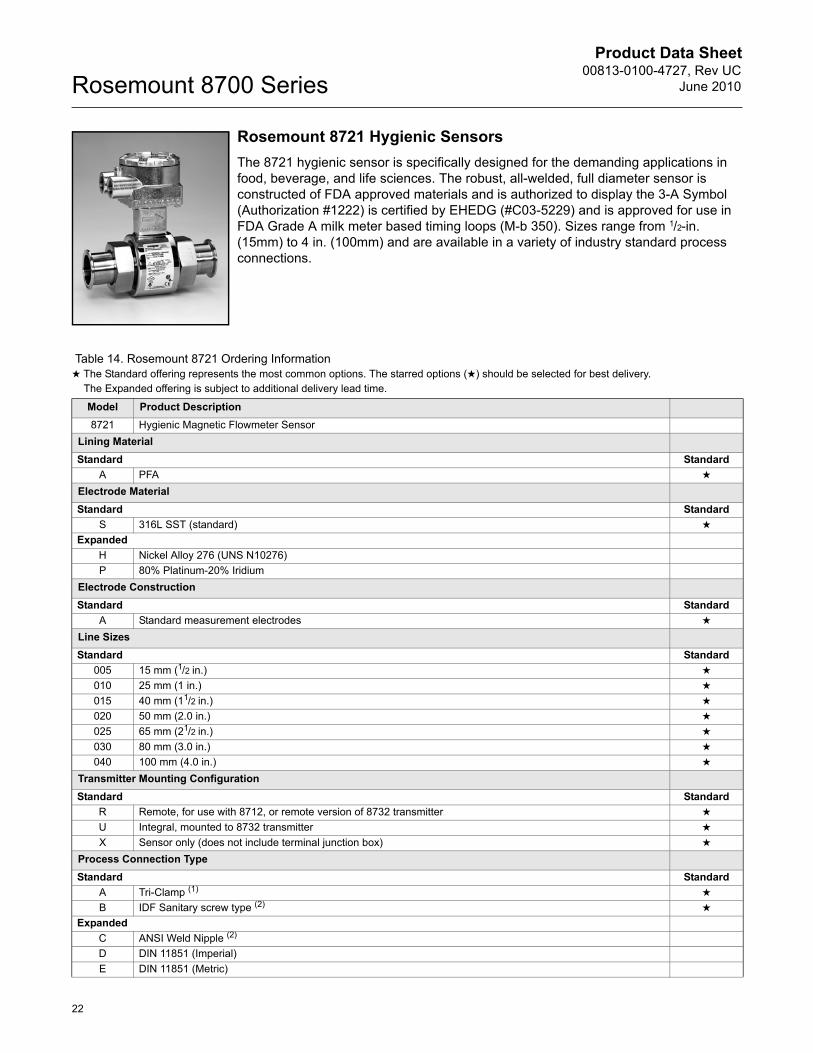
Rosemount 8721 Hygienic SensorsThe 8721 hygienic sensor is specifically designed for the demanding applications in food, beverage, and life sciences. The robust, all-welded, full diameter sensor is constructed of FDA approved materials and is authorized to display the 3-A Symbol (Authorization #1222) is certified by EHEDG (#C03-5229) and is approved for use in FDA Grade A milk meter based timing loops (M-b 350). Sizes range from 1/2-in. (15mm) to 4 in. (100mm) and are available in a variety of industry standard process connections.
Table 14. Rosemount 8721 Ordering Information★ The Standard offering represents the most common options. The starred options (★) should be selected for best delivery.__The Expanded offering is subject to additional delivery lead time.
Model Product Description8721 Hygienic Magnetic Flowmeter Sensor
Lining MaterialStandard Standard
A PFA ★
Electrode MaterialStandard Standard
S 316L SST (standard) ★
ExpandedH Nickel Alloy 276 (UNS N10276)P 80% Platinum-20% Iridium
Electrode ConstructionStandard Standard
A Standard measurement electrodes ★
Line SizesStandard Standard
005 15 mm (1/2 in.) ★
010 25 mm (1 in.) ★
015 40 mm (11/2 in.) ★
020 50 mm (2.0 in.) ★
025 65 mm (21/2 in.) ★
030 80 mm (3.0 in.) ★
040 100 mm (4.0 in.) ★
Transmitter Mounting ConfigurationStandard Standard
R Remote, for use with 8712, or remote version of 8732 transmitter ★
U Integral, mounted to 8732 transmitter ★
X Sensor only (does not include terminal junction box) ★
Process Connection TypeStandard Standard
A Tri-Clamp (1) ★
B IDF Sanitary screw type (2) ★
ExpandedC ANSI Weld Nipple (2)
D DIN 11851 (Imperial)E DIN 11851 (Metric)
Product Data Sheet00813-0100-4727, Rev UCJune 2010
23
Rosemount 8700 Series
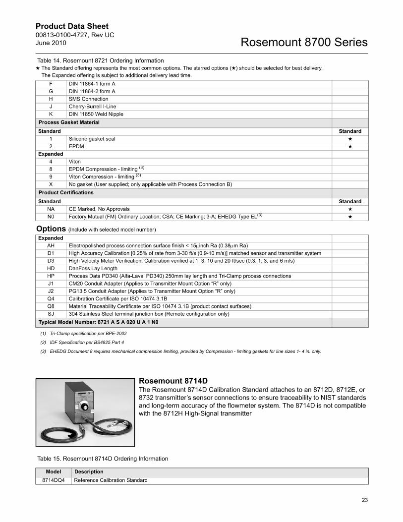
Rosemount 8714DThe Rosemount 8714D Calibration Standard attaches to an 8712D, 8712E, or 8732 transmitter’s sensor connections to ensure traceability to NIST standards and long-term accuracy of the flowmeter system. The 8714D is not compatible with the 8712H High-Signal transmitter
Table 15. Rosemount 8714D Ordering Information
F DIN 11864-1 form AG DIN 11864-2 form AH SMS ConnectionJ Cherry-Burrell I-LineK DIN 11850 Weld Nipple
Process Gasket Material Standard Standard
1 Silicone gasket seal ★
2 EPDM ★
Expanded4 Viton8 EPDM Compression - limiting (3)
9 Viton Compression - limiting (3)
X No gasket (User supplied; only applicable with Process Connection B)Product CertificationsStandard Standard
NA CE Marked, No Approvals ★
N0 Factory Mutual (FM) Ordinary Location; CSA; CE Marking; 3-A; EHEDG Type EL(3) ★
Options (Include with selected model number)Expanded
AH Electropolished process connection surface finish < 15Pinch Ra (0.38Pm Ra)D1 High Accuracy Calibration [0.25% of rate from 3-30 ft/s (0.9-10 m/s)] matched sensor and transmitter systemD3 High Velocity Meter Verification. Calibration verified at 1, 3, 10 and 20 ft/sec (0.3. 1, 3, and 6 m/s)HD DanFoss Lay LengthHP Process Data PD340 (Alfa-Laval PD340) 250mm lay length and Tri-Clamp process connectionsJ1 CM20 Conduit Adapter (Applies to Transmitter Mount Option “R” only)J2 PG13.5 Conduit Adapter (Applies to Transmitter Mount Option “R” only)Q4 Calibration Certificate per ISO 10474 3.1BQ8 Material Traceability Certificate per ISO 10474 3.1B (product contact surfaces)SJ 304 Stainless Steel terminal junction box (Remote configuration only)
Typical Model Number: 8721 A S A 020 U A 1 N0
(1) Tri-Clamp specification per BPE-2002
(2) IDF Specification per BS4825 Part 4
(3) EHEDG Document 8 requires mechanical compression limiting, provided by Compression - limiting gaskets for line sizes 1- 4 in. only.
Table 14. Rosemount 8721 Ordering Information★ The Standard offering represents the most common options. The starred options (★) should be selected for best delivery.__The Expanded offering is subject to additional delivery lead time.
Model Description8714DQ4 Reference Calibration Standard
Product Data Sheet00813-0100-4727, Rev UC
June 2010Rosemount 8700 Series
24
TaggingThe sensor and transmitter will be tagged, at no charge, in accordance with customer requirements.
Transmitter tag character height is 0.125 in. (3.18 mm). Sensor tag: 40 character maximum.Transmitter tag: see Configuration Data Sheet for character maximum.
Ordering Procedure To order, select the desired sensor and/or transmitter by specifying model codes from the ordering table.
For remote transmitter applications, note the cable specification requirements.
Sensors and transmitters must be selected from Product Data Sheet 00813-0100-4727.
Standard Configuration Unless the Configuration Data Sheet is completed, the transmitter will be shipped as follows:
Integrally Mounted Rosemount 8732E Transmitters are factory configured with the attached sensor size and appropriate calibration number.
Cable Requirements for Remote Transmitters
Remote transmitter installations require equal lengths of signal and coil drive cables. Integrally mounted transmitters are factory wired and do not require interconnecting cables.
Lengths from 5 to 1,000 ft. (1.5 to 300 m) may be specified, and will be shipped with the sensor. Cable longer than 100 ft. (30 m) is not recommended for high-signal systems.
Custom Configuration (Option Code C1)If Option Code C1 is ordered, the Configuration Data Sheet (CDS) must be submitted at the time of order.
Engineering Units: ft/sec4 mA (1 V DC): 020 mA (5 V DC): 30Sensor Size: 3-in.Empty Pipe: Off Sensor Calibration Number: 1000005010000000
Description Length P/NSignal Cable (20 AWG)
Belden 8762, Alpha 2411 equivalent
ftm
08712-0061-000108712-0061-2003
Coil Drive Cable (14 AWG) Belden 8720, Alpha 2442 equivalent
ftm
08712-0060-000108712-0060-2003
Combination Signal and Coil Drive Cable
(18 AWG)(1)
(1) Combination signal and coil drive cable is not recommended for high-signal magmeter system. For remote mount installations, combination signal and coil drive cable should be limited to less than 330 ft (100 m).
ftm
08712-0752-000108712-0752-2003
Product Data Sheet00813-0100-4727, Rev UCJune 2010
25
Rosemount 8700 Series
Rosemount 8700 Series Product Specifications Overview
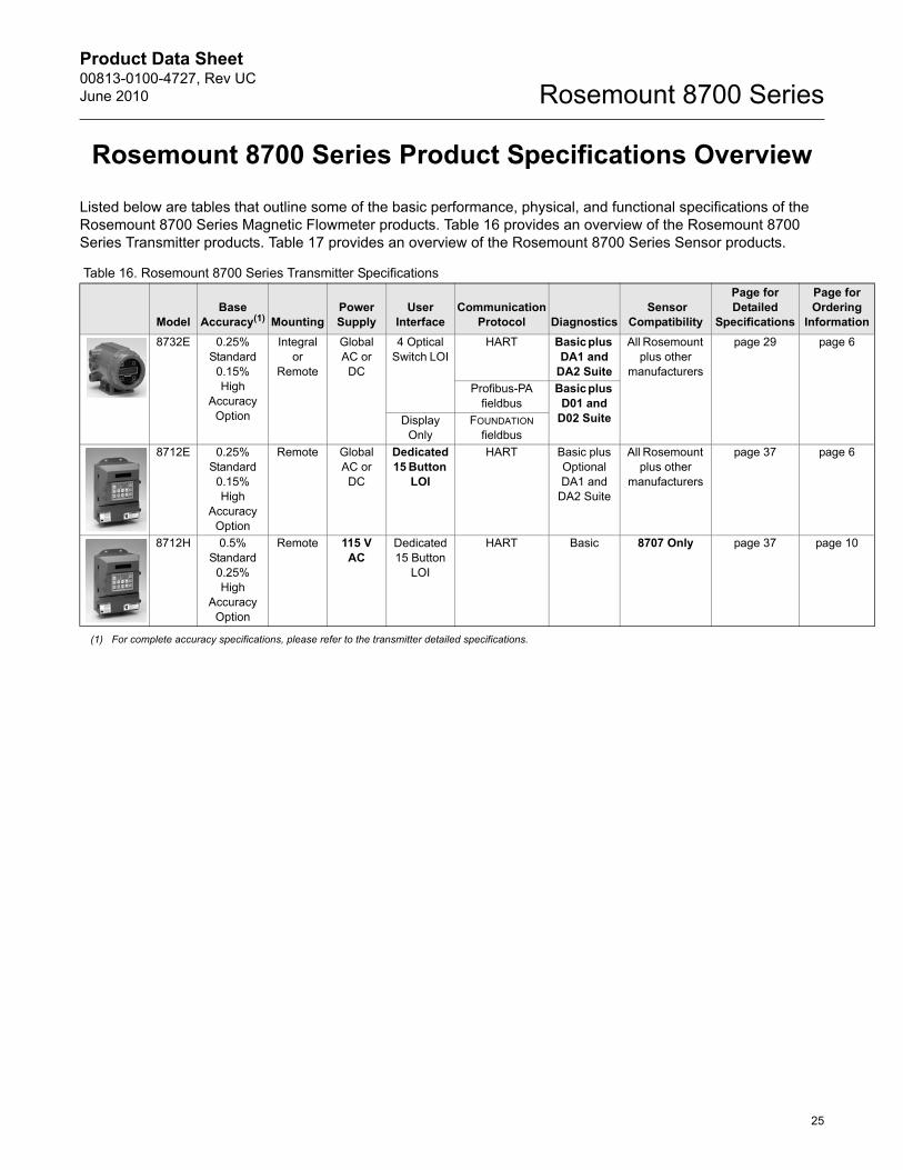
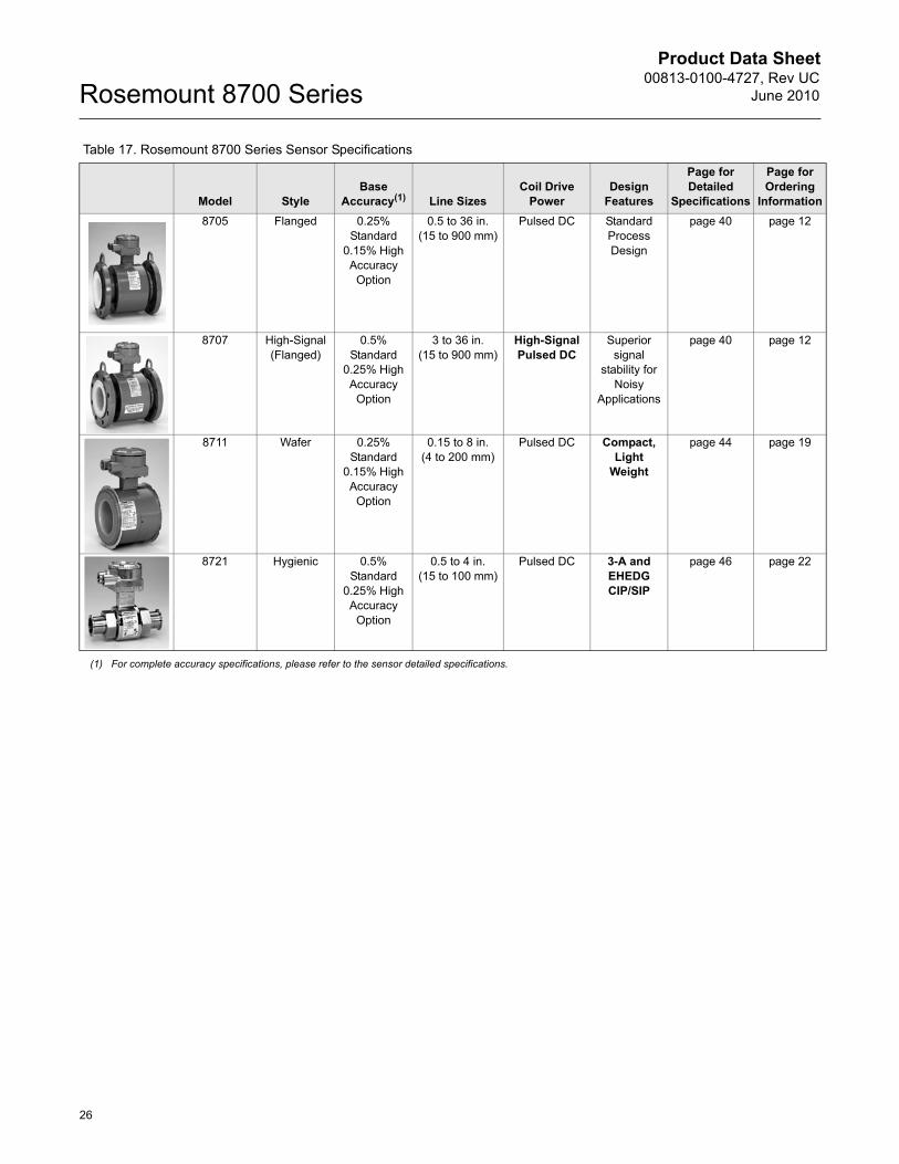
Listed below are tables that outline some of the basic performance, physical, and functional specifications of the Rosemount 8700 Series Magnetic Flowmeter products. Table 16 provides an overview of the Rosemount 8700 Series Transmitter products. Table 17 provides an overview of the Rosemount 8700 Series Sensor products.
Table 16. Rosemount 8700 Series Transmitter Specifications
ModelBase
Accuracy(1)
(1) For complete accuracy specifications, please refer to the transmitter detailed specifications.
MountingPower Supply
User Interface
Communication Protocol Diagnostics
Sensor Compatibility
Page for Detailed
Specifications
Page for Ordering
Information8732E 0.25%
Standard 0.15% High
Accuracy Option
Integral or
Remote
Global AC or DC
4 Optical Switch LOI
HART Basic plus DA1 and
DA2 Suite
All Rosemount plus other
manufacturers
page 29 page 6
Profibus-PA fieldbus
Basic plus D01 and
D02 SuiteDisplay Only
FOUNDATION fieldbus
8712E 0.25% Standard
0.15% High
Accuracy Option
Remote Global AC or DC
Dedicated 15 Button
LOI
HART Basic plus Optional DA1 and
DA2 Suite
All Rosemount plus other
manufacturers
page 37 page 6
8712H 0.5% Standard
0.25% High
Accuracy Option
Remote 115 V AC
Dedicated 15 Button
LOI
HART Basic 8707 Only page 37 page 10
Product Data Sheet00813-0100-4727, Rev UC
June 2010Rosemount 8700 Series
26
Table 17. Rosemount 8700 Series Sensor Specifications
Model StyleBase
Accuracy(1) Line SizesCoil Drive
PowerDesign
Features
Page for Detailed
Specifications
Page for Ordering
Information8705 Flanged 0.25%
Standard 0.15% High Accuracy
Option
0.5 to 36 in. (15 to 900 mm)
Pulsed DC Standard Process Design
page 40 page 12
8707 High-Signal (Flanged)
0.5% Standard
0.25% High Accuracy
Option
3 to 36 in. (15 to 900 mm)
High-Signal Pulsed DC
Superior signal
stability for Noisy
Applications
page 40 page 12
8711 Wafer 0.25% Standard
0.15% High Accuracy
Option
0.15 to 8 in. (4 to 200 mm)
Pulsed DC Compact, Light
Weight
page 44 page 19
8721 Hygienic 0.5% Standard
0.25% High Accuracy
Option
0.5 to 4 in. (15 to 100 mm)
Pulsed DC 3-A and EHEDG CIP/SIP
page 46 page 22
(1) For complete accuracy specifications, please refer to the sensor detailed specifications.
Product Data Sheet00813-0100-4727, Rev UCJune 2010
27
Rosemount 8700 Series
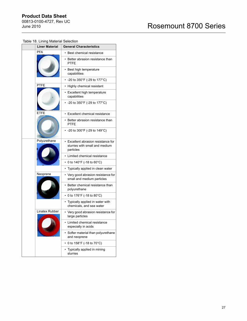
Table 18. Lining Material SelectionLiner Material General CharacteristicsPFA • Best chemical resistance
• Better abrasion resistance than PTFE
• Best high temperature capabilities
• -20 to 350°F (-29 to 177°C)
PTFE • Highly chemical resistant
• Excellent high temperature capabilities
• -20 to 350°F (-29 to 177°C)
ETFE • Excellent chemical resistance
• Better abrasion resistance than PTFE
• -20 to 300°F (-29 to 149°C)
Polyurethane • Excellent abrasion resistance for slurries with small and medium particles
• Limited chemical resistance
• 0 to 140°F (-18 to 60°C)
• Typically applied in clean water
Neoprene • Very good abrasion resistance for small and medium particles
• Better chemical resistance than polyurethane
• 0 to 176°F (-18 to 80°C)
• Typically applied in water with chemicals, and sea water
Linatex Rubber • Very good abrasion resistance for large particles
• Limited chemical resistance especially in acids
• Softer material than polyurethane and neoprene
• 0 to 158°F (-18 to 70°C)
• Typically applied in mining slurries
Product Data Sheet00813-0100-4727, Rev UC
June 2010Rosemount 8700 Series
28
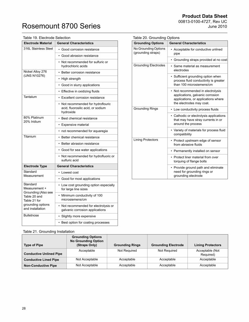
Table 19. Electrode Selection Table 20. Grounding Options
Table 21. Grounding Installation
Electrode Material General Characteristics316L Stainless Steel • Good corrosion resistance
• Good abrasion resistance
• Not recommended for sulfuric or hydrochloric acids
Nickel Alloy 276 (UNS N10276)
• Better corrosion resistance
• High strength
• Good in slurry applications
• Effective in oxidizing fluids
Tantalum • Excellent corrosion resistance
• Not recommended for hydroflouric acid, fluorosilic acid, or sodium hydroxide
80% Platinum20% Iridium
• Best chemical resistance
• Expensive material
• not recommended for aquaregia
Titanium • Better chemical resistance
• Better abrasion resistance
• Good for sea water applications
• Not recommended for hydrofluoric or sulfuric acid
Electrode Type General CharacteristicsStandard Measurement
• Lowest cost
• Good for most applications
Standard Measurement + Grounding (Also see Table 20 and Table 21 for grounding options and installation
• Low cost grounding option especially for large line sizes
• Minimum conductivity of 100 microsiemens/cm
• Not recommended for electrolysis or galvanic corrosion applications
Bulletnose • Slightly more expensive
• Best option for coating processes
Grounding Options General CharacteristicsNo Grounding Options (grounding straps)
• Acceptable for conductive unlined pipe
• Grounding straps provided at no cost
Grounding Electrodes • Same material as measurement electrodes
• Sufficient grounding option when process fluid conductivity is greater than 100 microsiemens/cm
• Not recommended in electrolysis applications, galvanic corrosion applications, or applications where the electrodes may coat.
Grounding Rings • Low conductivity process fluids
• Cathodic or electrolysis applications that may have stray currents in or around the process
• Variety of materials for process fluid compatibility
Lining Protectors • Protect upstream edge of sensor from abrasive fluids
• Permanently installed on sensor
• Protect liner material from over torquing of flange bolts
• Provide ground path and eliminate need for grounding rings or grounding electrode
Type of Pipe
Grounding Options No Grounding Option
(Straps Only) Grounding Rings Grounding Electrode Lining Protectors
Conductive Unlined PipeAcceptable Not Required Not Required Acceptable (Not
Required)Conductive Lined Pipe Not Acceptable Acceptable Acceptable Acceptable
Non-Conductive Pipe Not Acceptable Acceptable Acceptable Acceptable
Product Data Sheet00813-0100-4727, Rev UCJune 2010
29
Rosemount 8700 Series
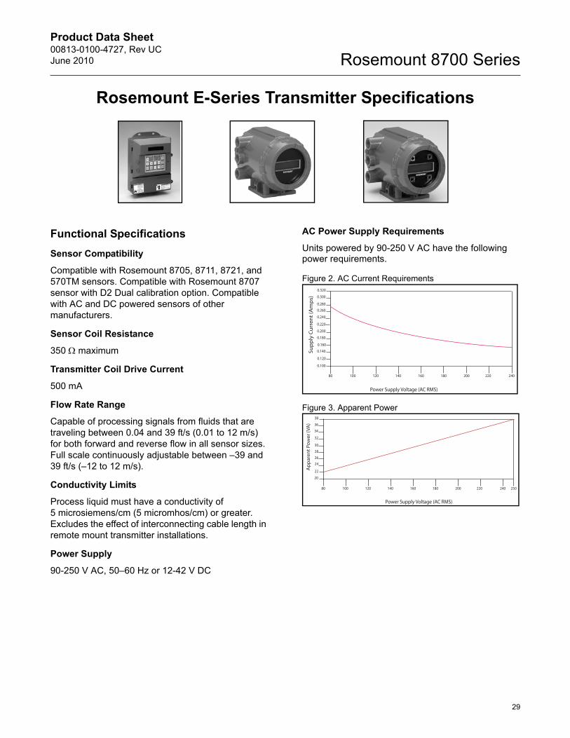
Rosemount E-Series Transmitter Specifications
Functional SpecificationsSensor Compatibility
Compatible with Rosemount 8705, 8711, 8721, and 570TM sensors. Compatible with Rosemount 8707 sensor with D2 Dual calibration option. Compatible with AC and DC powered sensors of other manufacturers.
Sensor Coil Resistance
350 : maximum
Transmitter Coil Drive Current
500 mA
Flow Rate Range
Capable of processing signals from fluids that are traveling between 0.04 and 39 ft/s (0.01 to 12 m/s) for both forward and reverse flow in all sensor sizes. Full scale continuously adjustable between –39 and 39 ft/s (–12 to 12 m/s).
Conductivity Limits
Process liquid must have a conductivity of 5 microsiemens/cm (5 micromhos/cm) or greater. Excludes the effect of interconnecting cable length in remote mount transmitter installations.
Power Supply
90-250 V AC, 50–60 Hz or 12-42 V DC
AC Power Supply Requirements
Units powered by 90-250 V AC have the following power requirements.
Figure 2. AC Current Requirements
Figure 3. Apparent Power
Supp
ly C
urre
nt (A
mps
)
0.100
0.120
0.140
0.180
0.200
0.220
0.240
0.2600.280
0.300
0.320
0.160
80 100 120 140 160 180 200 220 240
Power Supply Voltage (AC RMS)
80 100 120 140 160 180 200 220 240
Power Supply Voltage (AC RMS)
20
22
2426
28
30
32
34
36
38
App
aren
t Pow
er (V
A)
250
Product Data Sheet00813-0100-4727, Rev UC
June 2010Rosemount 8700 Series
30
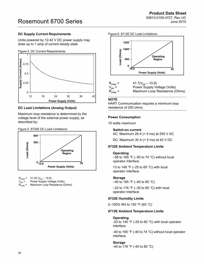
DC Supply Current Requirements
Units powered by 12-42 V DC power supply may draw up to 1 amp of current steady state.
Figure 4. DC Current Requirements
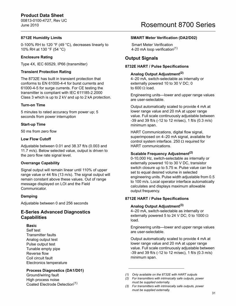
DC Load Limitations (Analog Output)
Maximum loop resistance is determined by the voltage level of the external power supply, as described by:
Figure 5. 8732E DC Load Limitations
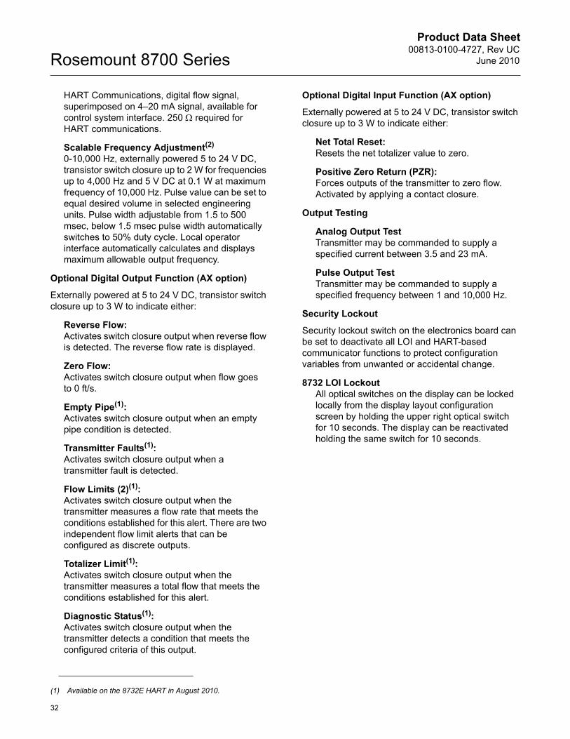
Figure 6. 8712E DC Load Limitations
NOTEHART Communication requires a minimum loop resistance of 250 ohms.
Power Consumption
10 watts maximum
Switch-on currentAC: Maximum 26 A (< 5 ms) at 250 V AC
DC: Maximum 30 A (< 5 ms) at 42 V DC
8732E Ambient Temperature Limits
Operating–58 to 165 °F (–50 to 74 °C) without local operator interface
13 to 149 °F (–25 to 65 °C) with local operator interface
Storage–40 to 185 °F (–40 to 85 °C)
–22 to 176 °F (–30 to 80 °C) with local operator interface
8732E Humidity Limits
0–100% RH to 150 °F (65 °C)
8712E Ambient Temperature Limits
Operating-20 to 140 °F (-29 to 60 °C) with local operator interface
-40 to 165 °F (-40 to 74 °C) without local operator interface
Storage-40 to 176 °F (-40 to 80 °C)
Rmax = 31.25 (Vps – 10.8)Vps = Power Supply Voltage (Volts)Rmax = Maximum Loop Resistance (Ohms)
0
0.25
0.5
0.75
1
12 18 24 30 36 42
Power Supply (Volts)
Supp
ly C
urre
nt (A
mps
)
Power Supply (Volts)
Load
(Ohm
s)
OperatingRegion
600
500
0 10.8 30
Rmax = 41.7(Vps – 10.8)Vps = Power Supply Voltage (Volts)Rmax = Maximum Loop Resistance (Ohms)
Power Supply (Volts)
Load
(Ohm
s)
OperatingRegion
1250
1000
500
010.8 42
Product Data Sheet00813-0100-4727, Rev UCJune 2010
31
Rosemount 8700 Series
8712E Humidity Limits
0-100% RH to 120 °F (49 °C), decreases linearly to 10% RH at 130 °F (54 °C)
Enclosure Rating
Type 4X, IEC 60529, IP66 (transmitter)
Transient Protection Rating
The 8732E has built in transient protection that conforms to EN 61000-4-4 for burst currents and 61000-4-5 for surge currents. For CE testing the transmitter is compliant with IEC 611185-2.2000 Class 3 which is up to 2 kV and up to 2 kA protection.
Turn-on Time
5 minutes to rated accuracy from power up; 5 seconds from power interruption
Start-up Time
50 ms from zero flow
Low Flow Cutoff
Adjustable between 0.01 and 38.37 ft/s (0.003 and 11.7 m/s). Below selected value, output is driven to the zero flow rate signal level.
Overrange Capability
Signal output will remain linear until 110% of upper range value or 44 ft/s (13 m/s). The signal output will remain constant above these values. Out of range message displayed on LOI and the Field Communicator.
Damping
Adjustable between 0 and 256 seconds
E-Series Advanced Diagnostics Capabilities
BasicSelf testTransmitter faultsAnalog output testPulse output testTunable empty pipeReverse flowCoil circuit faultElectronics temperature
Process Diagnostics (DA1/D01)Ground/wiring faultHigh process noiseCoated Electrode Detection(1)
SMART Meter Verification (DA2/D02)
Smart Meter Verification4-20 mA loop verification(1)
Output Signals8732E HART / Pulse Specifications
Analog Output Adjustment(2)
4–20 mA, switch-selectable as internally or externally powered 10 to 30 V DC; 0 to 600 : load.
Engineering units—lower and upper range values are user-selectable.
Output automatically scaled to provide 4 mA at lower range value and 20 mA at upper range value. Full scale continuously adjustable between -39 and 39 ft/s (-12 to 12 m/sec), 1 ft/s (0.3 m/s) minimum span.
HART Communications, digital flow signal, superimposed on 4–20 mA signal, available for control system interface. 250 : required for HART communications.
Scalable Frequency Adjustment(2)
0-10,000 Hz, switch-selectable as internally or externally powered 10 to 30 V DC, transistor switch closure up to 5.75 w. Pulse value can be set to equal desired volume in selected engineering units. Pulse width adjustable from 0.5 to 100 m/s. Local operator interface automatically calculates and displays maximum allowable output frequency.
8712E HART / Pulse Specifications
Analog Output Adjustment(3)
4–20 mA, switch-selectable as internally or externally powered 5 to 24 V DC; 0 to 1000 :�load.
Engineering units—lower and upper range values are user-selectable.
Output automatically scaled to provide 4 mA at lower range value and 20 mA at upper range value. Full scale continuously adjustable between -39 and 39 ft/s (-12 to 12 m/sec), 1 ft/s (0.3 m/s) minimum span.
(1) Only available on the 8732E with HART outputs(2) For transmitters with intrinsically safe outputs, power
must be supplied externally.(3) For transmitters with intrinsically safe outputs, power
must be supplied externally.
Product Data Sheet00813-0100-4727, Rev UC
June 2010Rosemount 8700 Series
32
HART Communications, digital flow signal, superimposed on 4–20 mA signal, available for control system interface. 250 : required for HART communications.
Scalable Frequency Adjustment(2)
0-10,000 Hz, externally powered 5 to 24 V DC, transistor switch closure up to 2 W for frequencies up to 4,000 Hz and 5 V DC at 0.1 W at maximum frequency of 10,000 Hz. Pulse value can be set to equal desired volume in selected engineering units. Pulse width adjustable from 1.5 to 500 msec, below 1.5 msec pulse width automatically switches to 50% duty cycle. Local operator interface automatically calculates and displays maximum allowable output frequency.
Optional Digital Output Function (AX option)
Externally powered at 5 to 24 V DC, transistor switch closure up to 3 W to indicate either:
Reverse Flow: Activates switch closure output when reverse flow is detected. The reverse flow rate is displayed.
Zero Flow: Activates switch closure output when flow goes to 0 ft/s.
Empty Pipe(1):Activates switch closure output when an empty pipe condition is detected.
Transmitter Faults(1):Activates switch closure output when a transmitter fault is detected.
Flow Limits (2)(1):Activates switch closure output when the transmitter measures a flow rate that meets the conditions established for this alert. There are two independent flow limit alerts that can be configured as discrete outputs.
Totalizer Limit(1):Activates switch closure output when the transmitter measures a total flow that meets the conditions established for this alert.
Diagnostic Status(1):Activates switch closure output when the transmitter detects a condition that meets the configured criteria of this output.
Optional Digital Input Function (AX option)
Externally powered at 5 to 24 V DC, transistor switch closure up to 3 W to indicate either:
Net Total Reset: Resets the net totalizer value to zero.
Positive Zero Return (PZR): Forces outputs of the transmitter to zero flow. Activated by applying a contact closure.
Output Testing
Analog Output TestTransmitter may be commanded to supply a specified current between 3.5 and 23 mA.
Pulse Output TestTransmitter may be commanded to supply a specified frequency between 1 and 10,000 Hz.
Security Lockout
Security lockout switch on the electronics board can be set to deactivate all LOI and HART-based communicator functions to protect configuration variables from unwanted or accidental change.
8732 LOI LockoutAll optical switches on the display can be locked locally from the display layout configuration screen by holding the upper right optical switch for 10 seconds. The display can be reactivated holding the same switch for 10 seconds.
(1) Available on the 8732E HART in August 2010.
Product Data Sheet00813-0100-4727, Rev UCJune 2010
33
Rosemount 8700 Series
FOUNDATION fieldbus Digital Output SpecificationsOutput Signal
Manchester-encoded digital signal that conforms to IEC 1158-2 and ISA 50.02
Schedule Entries
Seven (7)
Links
Twenty (20)
Virtual Communications Relationships (VCRs)
One (1) predefined (F6, F7) Nineteen (19) configurable (see Table 1)
FOUNDATION fieldbus Function Blocks
Transducer BlockThe transducer block calculates flow from the measured induced voltage. The calculation includes information related to the calibration number, line size, and diagnostics.
Resource BlockThe resource block contains physical transmitter information, including available memory, manufacturer identification, device type, software tag, and unique identification.
Backup Link Active Scheduler (LAS)The transmitter is classified as a device link master. A device link master can function as a Link Active Scheduler (LAS) if the current link master device fails or is removed from the segment.
The host or other configuration tool is used to download the schedule for the application to the link master device. In the absence of a primary link master, the transmitter will claim the LAS and provide permanent control for the H1 segment.
DiagnosticsThe transmitter automatically performs continuous self-diagnostics. The user can perform on-line testing of the transmitter digital signal. Advanced simulation diagnostics are available. This enables remote verification of the electronics via a flow signal generator built into the electronics. The sensor strength value can be used to view the process flow signal and provide information regarding filter settings.
Analog Input
The AI function block processes the measurement and makes it available to other function blocks. The AI function block also allows filtering, alarming, and engineering unit changes.
The 8732E Transmitter with FOUNDATION fieldbus comes standard with one AI function block for flow.
Arithmetic Block
Provides pre-defined application-based equations including flow with partial density compensation, electronic remote seals, hydrostatic tank gauging, ratio control and others.
Proportional/Integral/Derivative
The optional PID function block provides a sophisticated implementation of the universal PID algorithm. The PID function block features input for feed forward control, alarms on the process variable, and control deviation. The PID type (series or Instrument Society of America [ISA]) is user-selectable on the derivative filter.
IntegratorThe standard integrator block is available for totalization of flow.
Reverse Flow
Detects and reports reverse flow
Software Lockout
A write-lock switch and software lockout are provided in the resource function block.
TotalizerNon-volatile totalizer for net, gross, forward and reverse totals.
Block Execution Time (Milliseconds)Resource (RB) —
Transducer (TB) —Analog Input (AI) 10
Proportional/Integral/Derivative (PID)
10
Integrator (INT) 10Arithmetic (AR) 10
Product Data Sheet00813-0100-4727, Rev UC
June 2010Rosemount 8700 Series
34
Profibus-PA fieldbus Digital Output SpecificationsOutput Signal
Manchester-encoded digital signal that conforms to IEC 1158-2 and ISA 50.02.
Profile Version
3.01
Identification Number
Generic: 0x9740
Manufacturer Specific: 0x0C15
Profibus-PA Function BlocksResource Block
The Resource Block contains physical transmitter information, including available memory, manufacturer identification, device type, software tag, and unique identification.
Transducer Block
The transducer block calculates flow from the measured induced voltage and provides the PV Variable input to the AI Block. The calculation includes information related to the calibration number, line size, and diagnostics.
Diagnostics
The transmitter automatically performs continuous self-diagnostics. The user can perform on-line testing of the transmitter digital signal. In addition advanced diagnostic capabilities are also available to give better insight to meter performance and process information.
Analog Input Block
The AI function block processes the measurement and makes it available to the Host system. The AI function block also allows filtering, alarming, and engineering unit changes. The 8732E Transmitter with Profibus-PA digital fieldbus comes standard with one AI function block flow.
Totalizer Block (3 blocks)
The Totalizer function block allows for totalization of the flow signal. The 8732E Transmitter with Profibus-PA digital fieldbus comes with 3 independent totalizer blocks. Each totalized value can be displayed on the Local Operator Interface of the device in addition to the Primary Variable. The non-volatile totalizers can be configured to measure gross, net, forward, and reverse totals.
Sensor Compensation
Rosemount sensors are flow-calibrated and assigned a calibration factor at the factory. The calibration factor is entered into the transmitter, enabling interchangeability of sensors without calculations or a compromise in standard accuracy.
8732E transmitters and other manufacturers’ sensors can be calibrated at known process conditions or at the Rosemount NIST-Traceable Flow Facility. Transmitters calibrated on site require a two-step procedure to match a known flow rate. This procedure can be found in the Operations Manual:
Product Data Sheet00813-0100-4727, Rev UCJune 2010
35
Rosemount 8700 Series
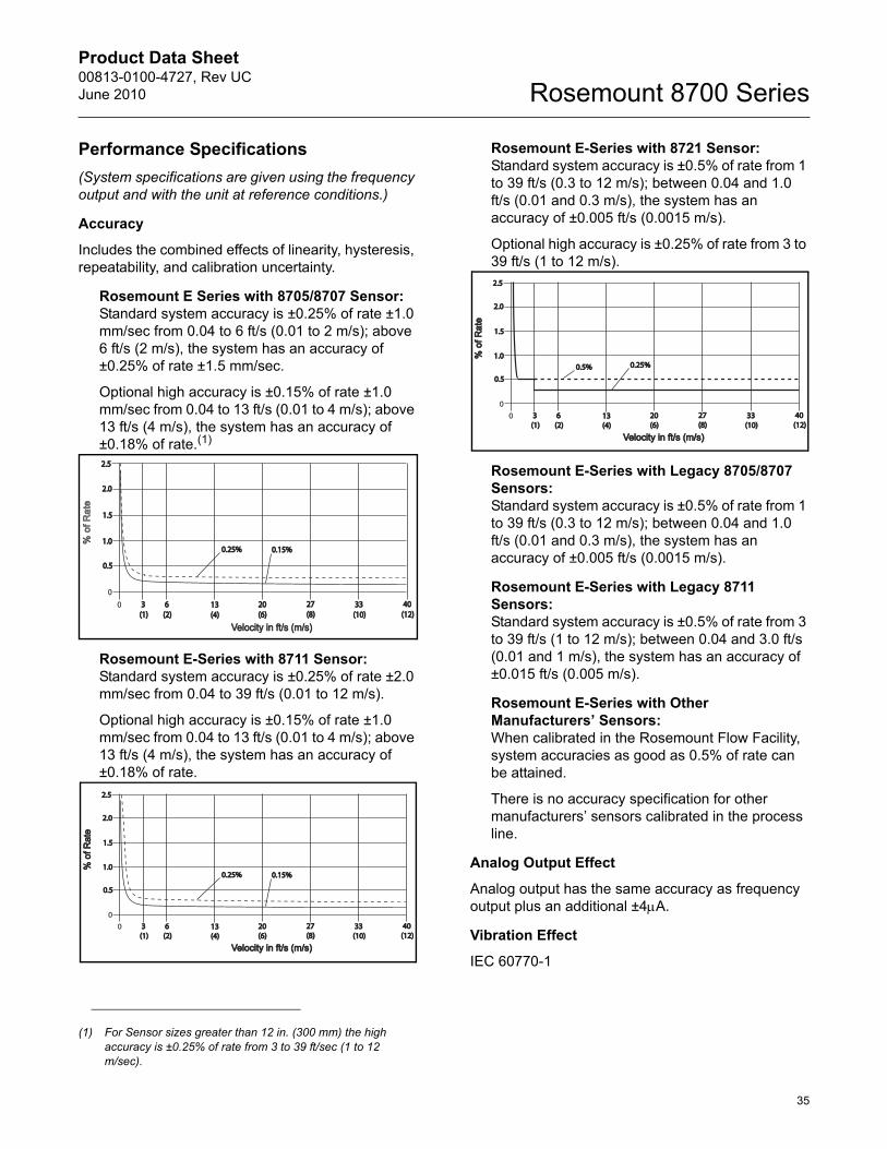
Performance Specifications(System specifications are given using the frequency output and with the unit at reference conditions.)
Accuracy
Includes the combined effects of linearity, hysteresis, repeatability, and calibration uncertainty.
Rosemount E Series with 8705/8707 Sensor:Standard system accuracy is ±0.25% of rate ±1.0 mm/sec from 0.04 to 6 ft/s (0.01 to 2 m/s); above 6 ft/s (2 m/s), the system has an accuracy of ±0.25% of rate ±1.5 mm/sec.
Optional high accuracy is ±0.15% of rate ±1.0 mm/sec from 0.04 to 13 ft/s (0.01 to 4 m/s); above 13 ft/s (4 m/s), the system has an accuracy of ±0.18% of rate.(1)
Rosemount E-Series with 8711 Sensor:Standard system accuracy is ±0.25% of rate ±2.0 mm/sec from 0.04 to 39 ft/s (0.01 to 12 m/s).
Optional high accuracy is ±0.15% of rate ±1.0 mm/sec from 0.04 to 13 ft/s (0.01 to 4 m/s); above 13 ft/s (4 m/s), the system has an accuracy of ±0.18% of rate.
Rosemount E-Series with 8721 Sensor:Standard system accuracy is ±0.5% of rate from 1 to 39 ft/s (0.3 to 12 m/s); between 0.04 and 1.0 ft/s (0.01 and 0.3 m/s), the system has an accuracy of ±0.005 ft/s (0.0015 m/s).
Optional high accuracy is ±0.25% of rate from 3 to 39 ft/s (1 to 12 m/s).
Rosemount E-Series with Legacy 8705/8707 Sensors:Standard system accuracy is ±0.5% of rate from 1 to 39 ft/s (0.3 to 12 m/s); between 0.04 and 1.0 ft/s (0.01 and 0.3 m/s), the system has an accuracy of ±0.005 ft/s (0.0015 m/s).
Rosemount E-Series with Legacy 8711 Sensors:Standard system accuracy is ±0.5% of rate from 3 to 39 ft/s (1 to 12 m/s); between 0.04 and 3.0 ft/s (0.01 and 1 m/s), the system has an accuracy of ±0.015 ft/s (0.005 m/s).
Rosemount E-Series with Other Manufacturers’ Sensors: When calibrated in the Rosemount Flow Facility, system accuracies as good as 0.5% of rate can be attained.
There is no accuracy specification for other manufacturers’ sensors calibrated in the process line.
Analog Output Effect
Analog output has the same accuracy as frequency output plus an additional ±4PA.
Vibration Effect
IEC 60770-1
(1) For Sensor sizes greater than 12 in. (300 mm) the high accuracy is ±0.25% of rate from 3 to 39 ft/sec (1 to 12 m/sec).
0
0.50.5
1.01.0
1.51.5
2.02.0
2.52.5
0 3 3 (1)(1)
6 6 (2)(2)
13 13 (4)(4)
20 20 (6)(6)
27 27 (8)(8)
33 33 (10)(10)
40 40 (12)(12)
Velocity in ft/s (m/s)Velocity in ft/s (m/s)
% o
f Rat
e
0.25%0.25% 0.15%0.15%
0
0.50.5
1.01.0
1.51.5
2.02.0
2.52.5
0 3 3 (1)(1)
6 6 (2)(2)
13 13 (4)(4)
20 20 (6)(6)
27 27 (8)(8)
33 33 (10)(10)
40 40 (12)(12)
Velocity in ft/s (m/s)Velocity in ft/s (m/s)
% o
f Rat
e%
of R
ate
0.25%0.25% 0.15%0.15%
0
0.50.5
1.01.0
1.51.5
2.02.0
2.52.5
0 3 3 (1)(1)
6 6 (2)(2)
13 13 (4)(4)
20 20 (6)(6)
27 27 (8)(8)
33 33 (10)(10)
40 40 (12)(12)
Velocity in ft/s (m/s)Velocity in ft/s (m/s)
% o
f Rat
e%
of R
ate
0.5%0.5% 0.25%0.25%
Product Data Sheet00813-0100-4727, Rev UC
June 2010Rosemount 8700 Series
36
Repeatability
±0.1% of reading
Response Time (Analog Output)
50 ms maximum response time to step change in input
Stability
±0.1% of rate over six months
Ambient Temperature Effect
±0.25% change over operating temperature range
EMC Compliance
EN61326-1: 2006 (Industrial) electromagnetic compatibility (EMC) for process and laboratory apparatus.
8732E Physical SpecificationsMaterials of Construction
HousingLow copper aluminum, Type 4X and IEC 60529 IP66
PaintPolyurethane
Cover GasketRubber
Electrical Connections
Two 1/2–14 NPT connections provided on the transmitter housing (optional third connection available). PG13.5 and CM20 adapters are available. Screw terminals provided for all connections. Power wiring connected to transmitter only. Integrally mounted transmitters are factory wired to the sensor.
Transmitter Weight
Approximately 7 lbs. (3.2 kg). Add 1 pound (0.5 kg) for Option Code M4/M5.
8712E Physical SpecificationsMaterials of Construction
HousingLow-copper aluminum, Type 4X and IEC 60529 IP66
PaintPolyurethane
Cover GasketRubber
Electrical Connections
Four 1/2–14 NPT connections provided on the base of the transmitter. Screw terminals provided for all of the connections. Power wiring connected to the transmitter only. Remote mounted transmitters require only a single conduit connection to the sensor.
Line Power Fuses
90–250 V ac systems 2 amp, Quick-acting Bussman AGCI or equivalent
12–42 V DC systems3 amp, Quick-acting Bussman AGCI or equivalent
Transmitter Weight
Transmitter approximately 9 lbs. (4 kg). Add 1 lb (0.5 kg) for local operator interface.
Product Data Sheet00813-0100-4727, Rev UCJune 2010
37
Rosemount 8700 Series
Rosemount 8712H Transmitter Specifications
Functional SpecificationsSensor Compatibility
Compatible with 8707 High-Signal sensor only.
Sensor Coil Resistance
Transmitter Coil Drive Current
5 A
Flow Rate Range
Capable of processing signals from fluids that are traveling between 0.04 and 30 ft/s (0.01 to 10 m/s) for both forward and reverse flow in all sensor sizes. Full scale continuously adjustable between –30 and 30 ft/s (–10 to 10 m/s).
Conductivity Limits
Process liquid must have a conductivity of 50 microsiemens/cm (50 micromhos/cm). Excludes the effect of interconnecting cable length in remote mount transmitter installations.
Power Supply
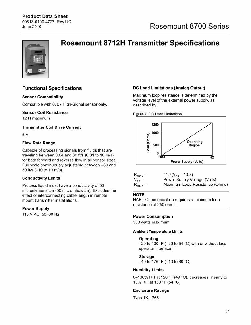
DC Load Limitations (Analog Output)
Maximum loop resistance is determined by the voltage level of the external power supply, as described by:
Figure 7. DC Load Limitations
NOTEHART Communication requires a minimum loop resistance of 250 ohms.
Power Consumption
Ambient Temperature Limits
Operating–20 to 130 °F (–29 to 54 °C) with or without local operator interface
Storage–40 to 176 °F (–40 to 80 °C)
Humidity Limits
0–100% RH at 120 °F (49 °C), decreases linearly to 10% RH at 130 °F (54 °C)
Enclosure Ratings
Type 4X, IP66
12 ! maximum
115 V AC, 50–60 Hz
Rmax = 41.7(Vps – 10.8)Vps = Power Supply Voltage (Volts)Rmax = Maximum Loop Resistance (Ohms)
300 watts maximum
Power Supply (Volts)
Load
(Ohm
s)
OperatingRegion
1250
1000
500
010.8 42
Product Data Sheet00813-0100-4727, Rev UC
June 2010Rosemount 8700 Series
38
Output Signals
Analog Output Adjustment4–20 mA, switch-selectable as internally or externally powered 5 to 24 V DC; 0 to 1000 : load.
Engineering units—lower and upper range values are user-selectable.
Output automatically scaled to provide 4 mA at lower range value and 20 mA at upper range value.
Full scale continuously adjustable between -30 and 30 ft/s (-10 to 10 m/sec), 1 ft/s (0.3 m/s) minimum span.
HART Communications, digital flow signal, superimposed on 4–20 mA signal, available for control system interface. 250 : required for HART communications.
Scalable Frequency Adjustment0-1000 Hz, externally powered at 5 to 24 V DC, transistor switch closure up to 5.75 W. Pulse value can be set to equal desired volume in selected engineering units. Pulse width adjustable from 0.5 to 100 m/s. Local operator interface automatically calculates and displays maximum allowable output frequency.
Auxiliary Output Function
Externally powered at 5 to 24 V DC, transistor switch closure up to 3 W to indicate either:
Reverse Flow: Activates switch closure output when reverse flow is detected. The reverse flow rate is displayed.
Zero Flow: Activates switch closure output when flow goes to 0 ft/s.
Positive Zero Return (PZR)(1)
Forces outputs of the transmitter to the zero flow rate signal level. Activated by applying a contact closure.
Security Lockout
Security lockout jumper on the electronics board can be set to deactivate all LOI and HART-based communicator functions to protect configuration variables from unwanted or accidental change.
Output Testing
Analog Output TestTransmitter may be commanded to supply a specified current between 3.75 and 23.25 mA
Pulse Output TestTransmitter may be commanded to supply a specified frequency between 1 and 1000 Hz
Turn-on Time30 minutes to rated accuracy from power up, 5 seconds from power interruption
Start-up Time
0.2 seconds from zero flow
Low Flow Cutoff
Adjustable between 0.01 and 38.37 ft/s (0.003 and 11.7 m/s). Below selected value, output is driven to the zero flow rate signal level.
Overrange Capability
Signal output will remain linear until 110% of upper range value. The signal output will remain constant above these values. Out of range message displayed on LOI and the Field Communicator.
Damping
Adjustable between 0.2 and 256 seconds
Sensor Compensation
Rosemount sensors are flow-calibrated and assigned a calibration factor at the factory. The calibration factor is entered into the transmitter, enabling interchangeability of sensors without calculations or a compromise in accuracy.
(1) PZR is internally powered on the 8712H transmitter.
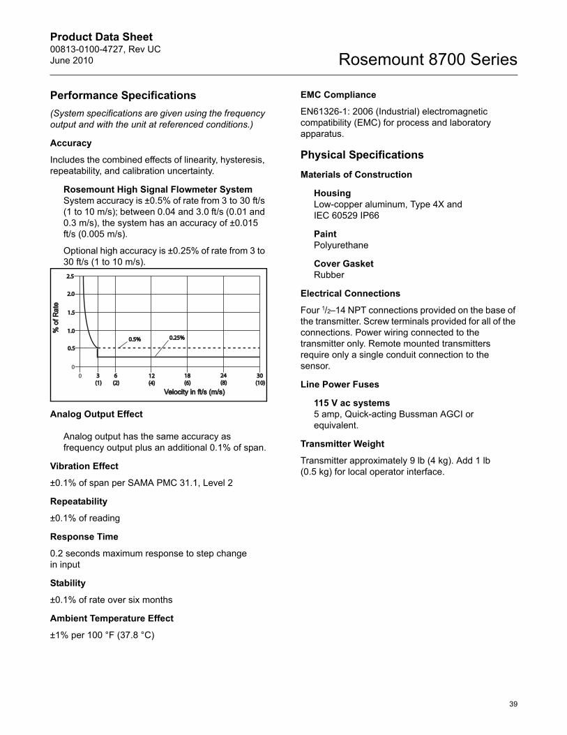
Product Data Sheet00813-0100-4727, Rev UCJune 2010
39
Rosemount 8700 Series
Performance Specifications(System specifications are given using the frequency output and with the unit at referenced conditions.)
Accuracy
Includes the combined effects of linearity, hysteresis, repeatability, and calibration uncertainty.
Rosemount High Signal Flowmeter SystemSystem accuracy is ±0.5% of rate from 3 to 30 ft/s (1 to 10 m/s); between 0.04 and 3.0 ft/s (0.01 and 0.3 m/s), the system has an accuracy of ±0.015 ft/s (0.005 m/s).
Optional high accuracy is ±0.25% of rate from 3 to 30 ft/s (1 to 10 m/s).
Analog Output Effect
Analog output has the same accuracy as frequency output plus an additional 0.1% of span.
Vibration Effect
±0.1% of span per SAMA PMC 31.1, Level 2
Repeatability
±0.1% of reading
Response Time
0.2 seconds maximum response to step change in input
Stability
±0.1% of rate over six months
Ambient Temperature Effect
±1% per 100 °F (37.8 °C)
EMC Compliance
EN61326-1: 2006 (Industrial) electromagnetic compatibility (EMC) for process and laboratory apparatus.
Physical SpecificationsMaterials of Construction
HousingLow-copper aluminum, Type 4X and IEC 60529 IP66
PaintPolyurethane
Cover GasketRubber
Electrical Connections
Four 1/2–14 NPT connections provided on the base of the transmitter. Screw terminals provided for all of the connections. Power wiring connected to the transmitter only. Remote mounted transmitters require only a single conduit connection to the sensor.
Line Power Fuses
115 V ac systems5 amp, Quick-acting Bussman AGCI or equivalent.
Transmitter Weight
Transmitter approximately 9 lb (4 kg). Add 1 lb (0.5 kg) for local operator interface.
0
0.50.5
1.01.0
1.51.5
2.02.0
2.52.5
0 3 3 (1)(1)
6 6 (2)(2)
12 12 (4)(4)
18 18 (6)(6)
24 24 (8)(8)
30 30 (10)(10)
Velocity in ft/s (m/s)Velocity in ft/s (m/s)
% o
f Rat
e%
of R
ate
0.5%0.5% 0.25%0.25%
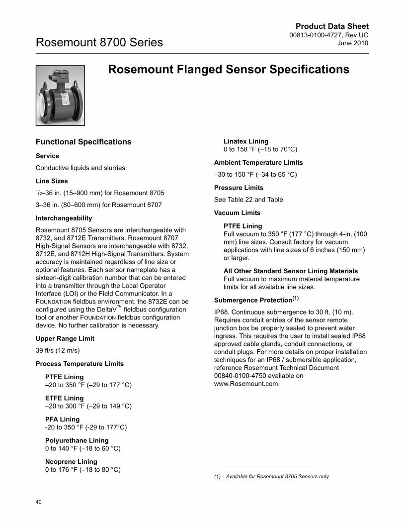
Product Data Sheet00813-0100-4727, Rev UC
June 2010Rosemount 8700 Series
40
Rosemount Flanged Sensor Specifications
Functional SpecificationsService
Conductive liquids and slurries
Line Sizes1/2–36 in. (15–900 mm) for Rosemount 8705
3–36 in. (80–600 mm) for Rosemount 8707
Interchangeability
Rosemount 8705 Sensors are interchangeable with 8732, and 8712E Transmitters. Rosemount 8707 High-Signal Sensors are interchangeable with 8732, 8712E, and 8712H High-Signal Transmitters. System accuracy is maintained regardless of line size or optional features. Each sensor nameplate has a sixteen-digit calibration number that can be entered into a transmitter through the Local Operator Interface (LOI) or the Field Communicator. In a FOUNDATION fieldbus environment, the 8732E can be configured using the DeltaV™ fieldbus configuration tool or another FOUNDATION fieldbus configuration device. No further calibration is necessary.
Upper Range Limit
39 ft/s (12 m/s)
Process Temperature Limits
PTFE Lining–20 to 350 °F (–29 to 177 °C)
ETFE Lining–20 to 300 °F (–29 to 149 °C)
PFA Lining-20 to 350 °F (-29 to 177°C)
Polyurethane Lining0 to 140 °F (–18 to 60 °C)
Neoprene Lining0 to 176 °F (–18 to 80 °C)
Linatex Lining0 to 158 °F (–18 to 70°C)
Ambient Temperature Limits
–30 to 150 °F (–34 to 65 °C)
Pressure Limits
See Table 22 and Table
Vacuum Limits
PTFE LiningFull vacuum to 350 °F (177 °C) through 4-in. (100 mm) line sizes. Consult factory for vacuum applications with line sizes of 6 inches (150 mm) or larger.
All Other Standard Sensor Lining MaterialsFull vacuum to maximum material temperature limits for all available line sizes.
Submergence Protection(1)
IP68. Continuous submergence to 30 ft. (10 m). Requires conduit entries of the sensor remote junction box be properly sealed to prevent water ingress. This requires the user to install sealed IP68 approved cable glands, conduit connections, or conduit plugs. For more details on proper installation techniques for an IP68 / submersible application, reference Rosemount Technical Document 00840-0100-4750 available on www.Rosemount.com.
(1) Available for Rosemount 8705 Sensors only.
Product Data Sheet00813-0100-4727, Rev UCJune 2010
41
Rosemount 8700 SeriesConductivity Limits
Process liquid must have a conductivity of 5 microsiemens/cm (5 micromhos/cm) or greater for 8705. Process liquid must have a conductivity of 50 microsiemens/cm (50 micromhos/cm) for 8707 when used with 8712H, 5 microsiemens/cm when used with other transmitters. Excludes the effect of interconnecting cable length in remote mount transmitter installations. Table 22. Temperature vs. Pressure Limits(1)
Sensor Temperature vs. Pressure Limits for ASME B16.5 Class Flanges (1/2- to 36-in. line sizes) (2)
Pressure
Flange Material Flange Rating@ -20 to 100 °F(-29 to 38 °C)
@ 200 °F(93 °C)
@ 300 °F(149 °C)
@ 350 °F(177 °C)
Carbon Steel
Class 150 285 psi 260 psi 230 psi 215 psiClass 300 740 psi 675 psi 655 psi 645 psi
Class 600 (3) 1000 psi 800 psi 700 psi 650 psiClass 600 (4) 1480 psi 1350 psi 1315 psi 1292 psi
Class 900 2220 psi 2025 psi 1970 psi 1935 psiClass 1500 3705 psi 3375 psi 3280 psi 3225 psiClass 2500 6170 psi 5625 psi 5470 psi 5375 psi
304 Stainless Steel
Class 150 275 psi 235 psi 205 psi 190 psiClass 300 720 psi 600 psi 530 psi 500 psi
Class 600 (5) 1000 psi 800 psi 700 psi 650 psiClass 600 (6) 1440 psi 1200 psi 1055 psi 997 psi
Class 900 2160 psi 1800 psi 1585 psi 1497 psiClass 1500 3600 psi 3000 psi 2640 psi 2495 psiClass 2500 6000 psi 5000 psi 4400 psi 4160 psi
(1) Liner temperature limits must also be considered. Polyurethane, Linatex, and Neoprene have temperature limits of 140 °F (60 °C), 158 °F (70 °C), and 176°F (80 °C), respectively.
(2) 30- and 36-in. AWWA C207 Table 23 Class D rated to 150 psi at atmospheric temperature.
(3) Option Code C6
(4) Option Code C7
(5) Option Code S6
(6) Option Code S7
Table 23. Temperature vs. Pressure Limits (1)
Sensor Temperature vs. Pressure Limits for AS2129 Table D and E Flanges (4- to 24-in. line sizes)
Pressure
Flange Material Flange Rating@ -200 to 50 °C(-320 to 122 °F)
@ 100 °C(212 °F)
@ 150 °C(302 °F)
@ 200 °C(392 °F)
Carbon SteelD 101.6 psi 101.6 psi 101.6 psi 94.3 psiE 203.1 psi 203.1 psi 203.1 psi 188.6 psi
(1) Liner temperature limits must also be considered. Polyurethane, Linatex, and Neoprene have temperature limits of 140 °F (60 °C), 158 °F (70 °C), and 176°F (80 °C), respectively.
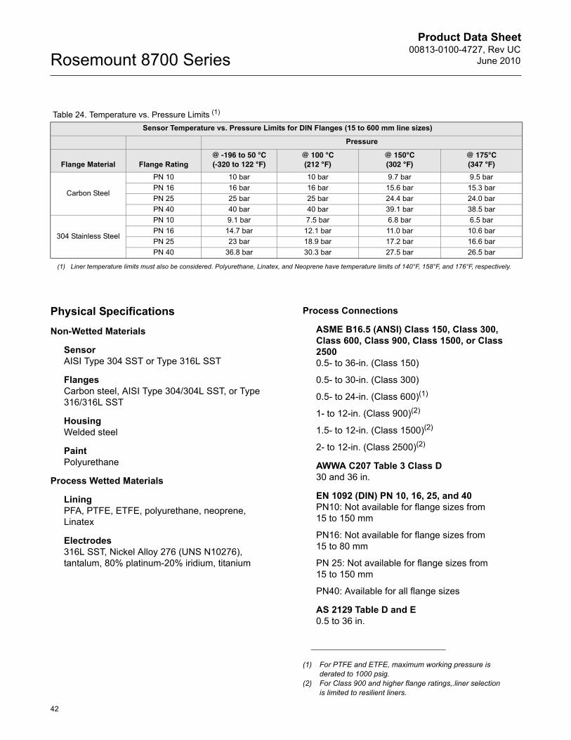
Product Data Sheet00813-0100-4727, Rev UC
June 2010Rosemount 8700 Series
42
Physical SpecificationsNon-Wetted Materials
SensorAISI Type 304 SST or Type 316L SST
FlangesCarbon steel, AISI Type 304/304L SST, or Type 316/316L SST
HousingWelded steel
PaintPolyurethane
Process Wetted Materials
LiningPFA, PTFE, ETFE, polyurethane, neoprene, Linatex
Electrodes316L SST, Nickel Alloy 276 (UNS N10276), tantalum, 80% platinum-20% iridium, titanium
Process Connections
ASME B16.5 (ANSI) Class 150, Class 300, Class 600, Class 900, Class 1500, or Class 25000.5- to 36-in. (Class 150)
0.5- to 30-in. (Class 300)
0.5- to 24-in. (Class 600)(1)
1- to 12-in. (Class 900)(2)
1.5- to 12-in. (Class 1500)(2)
2- to 12-in. (Class 2500)(2)
AWWA C207 Table 3 Class D30 and 36 in.
EN 1092 (DIN) PN 10, 16, 25, and 40PN10: Not available for flange sizes from 15 to 150 mm
PN16: Not available for flange sizes from 15 to 80 mm
PN 25: Not available for flange sizes from 15 to 150 mm
PN40: Available for all flange sizes
AS 2129 Table D and E0.5 to 36 in.
Table 24. Temperature vs. Pressure Limits (1)
Sensor Temperature vs. Pressure Limits for DIN Flanges (15 to 600 mm line sizes)
Pressure
Flange Material Flange Rating@ -196 to 50 °C(-320 to 122 °F)
@ 100 °C(212 °F)
@ 150°C(302 °F)
@ 175°C(347 °F)
Carbon Steel
PN 10 10 bar 10 bar 9.7 bar 9.5 barPN 16 16 bar 16 bar 15.6 bar 15.3 barPN 25 25 bar 25 bar 24.4 bar 24.0 barPN 40 40 bar 40 bar 39.1 bar 38.5 bar
304 Stainless Steel
PN 10 9.1 bar 7.5 bar 6.8 bar 6.5 barPN 16 14.7 bar 12.1 bar 11.0 bar 10.6 barPN 25 23 bar 18.9 bar 17.2 bar 16.6 barPN 40 36.8 bar 30.3 bar 27.5 bar 26.5 bar
(1) Liner temperature limits must also be considered. Polyurethane, Linatex, and Neoprene have temperature limits of 140°F, 158°F, and 176°F, respectively.
(1) For PTFE and ETFE, maximum working pressure is derated to 1000 psig.
(2) For Class 900 and higher flange ratings,.liner selection is limited to resilient liners.
Product Data Sheet00813-0100-4727, Rev UCJune 2010
43
Rosemount 8700 Series
Electrical Connections
Two 1/2–14 NPT connections with number 8 screw terminals are provided in the terminal enclosure for electrical wiring.
Grounding Electrode
An optional grounding electrode can be installed similarly to the measurement electrodes through the sensor lining on 8705 sensors. It is available in all electrode materials.
Grounding Rings
Optional grounding rings can be installed between the flange and the sensor face on both ends of the sensor. Single ground rings can be installed on either end of the sensor. They have an I.D. slightly larger than the sensor I.D. and an external tab to attach ground wiring. Grounding rings are available in 316L SST, Nickel Alloy 276 (UNS N10276), titanium, and tantalum.
Lining Protectors
Optional lining protectors can be installed between the flange and the sensor face on both ends of the sensor. The leading edge of lining material is protected by the lining protector; lining protectors cannot be removed once they are installed. Lining protectors are available in 316L SST, Nickel Alloy 276 (UNS N10276), and titanium.
Dimensions
See Figure 18.
Weight
See dimensional tables starting with Table 33 on page 63.
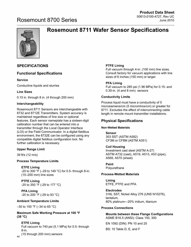
Product Data Sheet00813-0100-4727, Rev UC
June 2010Rosemount 8700 Series
44
Rosemount 8711 Wafer Sensor Specifications
SPECIFICATIONS
Functional SpecificationsService
Conductive liquids and slurries
Line Sizes
0.15 in. through 8 in. (4 through 200 mm)
Interchangeability
Rosemount 8711 Sensors are interchangeable with 8732 and 8712E Transmitters. System accuracy is maintained regardless of line size or optional features. Each sensor nameplate has a sixteen-digit calibration number that can be entered into a transmitter through the Local Operator Interface (LOI) or the Field Communicator. In a digital fieldbus environment, the 8732E can be configured using any compatible digital fieldbus configuration tool. No further calibration is necessary.
Upper Range Limit
39 ft/s (12 m/s)
Process Temperature Limits
ETFE Lining-20 to 300 °F (–29 to 149 °C) for 0.5- through 8-in.(15–200 mm) line sizes
PTFE Lining-20 to 350 °F (-29 to 177 °C)
PFA Lining-20 to 200 °F (-29 to 93 °C)
Ambient Temperature Limits
–30 to 150 °F (–34 to 65 °C)
Maximum Safe Working Pressure at 100 °F (38 °C)
ETFE LiningFull vacuum to 740 psi (5.1 MPa) for 0.5- through 8-in. (15 through 200 mm) sensors
PTFE LiningFull vacuum through 4-in. (100 mm) line sizes. Consult factory for vacuum applications with line sizes of 6 inches (150 mm) or larger.
PFA LiningFull vacuum to 285 psi (1.96 MPa) for 0.15- and 0.30-in. (4 and 8 mm) sensors
Conductivity Limits
Process liquid must have a conductivity of 5 microsiemens/cm (5 micromhos/cm) or greater for 8711. Excludes the effect of interconnecting cable length in remote mount transmitter installations.
Physical Specifications
Non-Wetted Materials
Sensor 303 SST (ASTM A582)CF3M or CF8M (ASTM A351)
Coil Housing Investment cast steel (ASTM A-27)ASTM A732 (cast), A519, A513, A53 (pipe), A569, A570 (sheet)
PaintPolyurethane
Process-Wetted Materials
LiningETFE, PTFE and PFA
Electrodes316L SST, Nickel Alloy 276 (UNS N10276), tantalum,80% platinum—20% iridium, titanium
Process Connections
Mounts between these Flange ConfigurationsASME B16.5 (ANSI): Class 150, 300
EN 1092 (DIN): PN 10 and 25
BS: 10 Table D, E, and F
Product Data Sheet00813-0100-4727, Rev UCJune 2010
45
Rosemount 8700 Series
Studs, Nuts, and Washers(1)
ASME B16.5 (ANSI)
0.15- through 1-in. (4 through 25 mm):316 SST, ASTM A193, Grade B8M, Class 1 threaded mounting studs; ASTM A194, Grade 8M heavy hex nuts; SAE per ANSI B18.2.1, Type A, Series N flat washers.
1.5- through 8-in. (40 through 200 mm):CS, ASTM A193, Grade B7, Class 1 threaded mounting studs; ASTM A194, Grade 2H heavy hex nuts; SAE per ANSI B18.2.1, Type A, Series N flat washers; all items clear, chromate zinc-plated.
EN 1092 (DIN)
4 through 25 mm (0.15- through 1-in.):316 SST ASTM A193, Grade B8M Class 1 threaded mounting studs; ASTM A194, Grade 8M, DIN 934 H=D, metric heavy hex nuts; 316 SST, A4, DIN 125 flat washers.
40 through 200 mm (1.5- through 8-in.):CS, ASTM A193, Grade B7 threaded mounting studs; ASTM A194, Grade 2H, DIN 934 H=D, metric heavy hex nuts; CS, DIN 125 flat washers; all items yellow zinc-plated.
Electrical Connections
Two 1/2–14 NPT connections with number 8 screw terminals are provided in the terminal enclosure for electrical wiring.
Grounding Electrode
An optional grounding electrode can be installed similarly to the measurement electrodes through the sensor lining. It is available in all electrode materials.
Grounding Rings
Optional grounding rings can be installed between the flange and the sensor face on both ends of the sensor. They have an I.D. slightly smaller than the sensor I.D. and an external tab to attach ground wiring. Grounding rings are available in 316L SST, Nickel Alloy 276 (UNS N10276), titanium, and tantalum.
Dimensions and Weight
See Figure 17-Figure 24 and Table 25.
(1) 0.15 and 0.30 in. (4 and 80 mm) sensors mount between 1/2-in. flange.
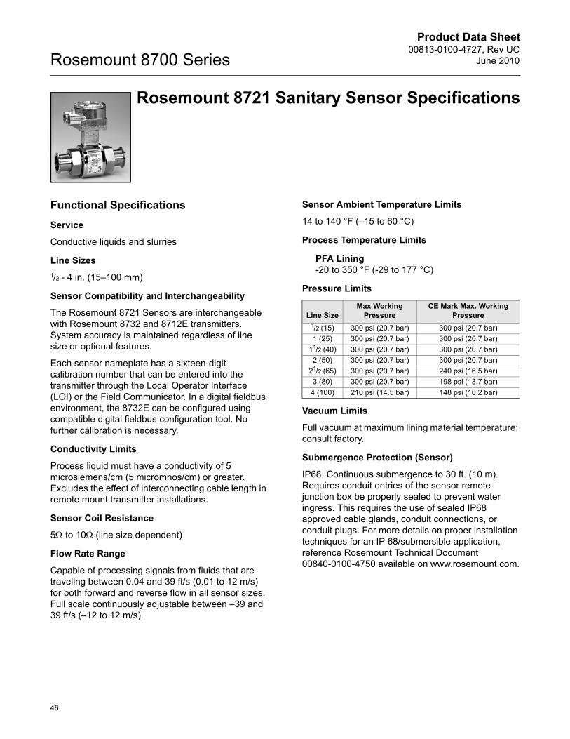
Product Data Sheet00813-0100-4727, Rev UC
June 2010Rosemount 8700 Series
46
Rosemount 8721 Sanitary Sensor Specifications
Functional SpecificationsService
Conductive liquids and slurries
Line Sizes1/2 - 4 in. (15–100 mm)
Sensor Compatibility and Interchangeability
The Rosemount 8721 Sensors are interchangeable with Rosemount 8732 and 8712E transmitters. System accuracy is maintained regardless of line size or optional features.
Each sensor nameplate has a sixteen-digit calibration number that can be entered into the transmitter through the Local Operator Interface (LOI) or the Field Communicator. In a digital fieldbus environment, the 8732E can be configured using compatible digital fieldbus configuration tool. No further calibration is necessary.
Conductivity Limits
Process liquid must have a conductivity of 5 microsiemens/cm (5 micromhos/cm) or greater. Excludes the effect of interconnecting cable length in remote mount transmitter installations.
Sensor Coil Resistance
5: to 10: (line size dependent)
Flow Rate Range
Capable of processing signals from fluids that are traveling between 0.04 and 39 ft/s (0.01 to 12 m/s) for both forward and reverse flow in all sensor sizes. Full scale continuously adjustable between –39 and 39 ft/s (–12 to 12 m/s).
Sensor Ambient Temperature Limits
14 to 140 °F (–15 to 60 °C)
Process Temperature Limits
PFA Lining-20 to 350 °F (-29 to 177 °C)
Pressure Limits
Vacuum Limits
Full vacuum at maximum lining material temperature; consult factory.
Submergence Protection (Sensor)
IP68. Continuous submergence to 30 ft. (10 m). Requires conduit entries of the sensor remote junction box be properly sealed to prevent water ingress. This requires the use of sealed IP68 approved cable glands, conduit connections, or conduit plugs. For more details on proper installation techniques for an IP 68/submersible application, reference Rosemount Technical Document 00840-0100-4750 available on www.rosemount.com.
Line SizeMax Working
PressureCE Mark Max. Working
Pressure1/2 (15) 300 psi (20.7 bar) 300 psi (20.7 bar)1 (25) 300 psi (20.7 bar) 300 psi (20.7 bar)
11/2 (40) 300 psi (20.7 bar) 300 psi (20.7 bar)2 (50) 300 psi (20.7 bar) 300 psi (20.7 bar)
21/2 (65) 300 psi (20.7 bar) 240 psi (16.5 bar)3 (80) 300 psi (20.7 bar) 198 psi (13.7 bar)
4 (100) 210 psi (14.5 bar) 148 psi (10.2 bar)
Product Data Sheet00813-0100-4727, Rev UCJune 2010
47
Rosemount 8700 Series
Physical SpecificationsMounting
Integrally mounted transmitters are factory-wired and do not require interconnecting cables. The transmitter can rotate in 90° increments. Remote mounted transmitters require only a single conduit connection to the sensor.
Non-Wetted Materials
Sensor304 Stainless Steel (wrapper), 304 Stainless Steel (pipe)
Terminal Junction BoxCast aluminum, polyurethane coatedOptional: 304 Stainless Steel
PaintPolyurethane
Weight
Aluminum remote junction boxApproximately 1 lb. (0.45 kg)
SST remote junction boxApproximately 2.5 lbs. (1.13 kg)
Process Wetted Materials (Sensor)
LinerPFA with Ra < 32P�in. (0.81 Pm)
Electrodes316L SST with Ra < 15P�in. (0.38 Pm)
Nickel Alloy 276 (UNS N10276) with Ra < 15P�in. (0.38 Pm)
80% Platinum-20% Iridium with Ra < 15P�in. (0.38 Pm)
Process Connections
The Rosemount 8721 Sanitary Sensor is designed using a standard IDF fitting as the basis for providing a flexible, hygienic interface for a variety of process connections. The Rosemount 8721 Sensor has the threaded or “male” end of the IDF fitting on the ends of the base sensor. The sensor can be directly connected with user supplied IDF fittings and gaskets. If other process connections are needed, the IDF fittings and gaskets can be provided and welded directly into the sanitary process tubing, or can be supplied with adapters to standard Tri-Clamp® process connections. All connections are PED compliant for group 2 fluids.
Tri-Clamp Sanitary Coupling
IDF Sanitary Coupling (screw type)IDF specification per BS4825 part 4
ANSI Weld Nipple
DIN 11850 Weld Nipple
DIN 11851 (Imperial and Metric)
DIN 11864-1 form A
DIN 11864-2 form A
SMS 1145
Cherry-Burrell I-Line
Process Connection Material
316L Stainless Steel with Ra < 32P in. (0.81Pm)
Optional Electropolished Surface Finish with Ra < 15P�in. (0.38P�m)
Process Connection Gasket Material
Silicone
EPDM
Viton
Electrical Connections
Two 1/2–14 NPT connections with number 8 screw terminals are provided in the terminal enclosure for electrical wiring.
Sensor Dimensions
Refer to Figure 17.
Table 25. 8721 Sensor Weight
Line Size Sensor Only008721-0350 Tri-Clamp
fitting (each)0.5 4.84 lbs (2.20 kg) 0.58 lbs (0.263 kg)1.0 4.52 lbs (2.05 kg) 0.68 lbs (0.309 kg)1.5 5.52 lbs (2.51 kg) 0.88 lbs (0.400 kg)2.0 6.78 lbs (3.08 kg) 1.30 lbs (0.591 kg)2.5 8.79 lbs (4.00 kg) 1.66 lbs (0.727 kg)3.0 13.26 lbs (6.03 kg) 2.22 lbs (1.01 kg)4.0 21.04 lbs (9.56 kg) 3.28 lbs (1.49 kg)
Product Data Sheet00813-0100-4727, Rev UC
June 2010Rosemount 8700 Series
48
Product Certifications
Approved Manufacturing LocationsRosemount Inc. — Eden Prairie, Minnesota, USAFisher-Rosemount Technologias de Flujo, S.A. de C.V. —
Chihuahua MexicoEmerson Process Management Flow — Ede, The NetherlandsAsia Flow Technologies Center — Nanjing, China
EUROPEAN DIRECTIVE INFORMATIONThe EC declaration of conformity for all applicable European directives for this product can be found on our website at www.rosemount.com. A hard copy may be obtained by contacting your local sales office.
ATEX DirectiveRosemount Inc. complies with the ATEX Directive.Type n protection type in accordance with EN50 021
• Closing of entries in the device must be carried out using the appropriate EEx e or EEx n metal cable gland and metal blanking plug or any appropriate ATEX approved cable gland and blanking plug with IP66 rating certified by an EU approved certification body.
For Rosemount 8732E transmitters:
Complies with Essential Health and Safety Requirements: EN 60079-0: 2006EN 60079-1: 2007EN 60079-7: 2007EN 60079-11: 2007EN 60079-15: 2005EN 61241-0: 2004EN 61241-1: 2006
For Rosemount 8712E transmitters:
Complies with Essential Health and Safety Requirements:EN 60079-15: 2003
For Rosemount 8700 Series Sensors:
Complies with Essential Health and Safety Requirements:EN 61241-0: 2006EN 61241-1: 2004
European Pressure Equipment Directive (PED) (97/23/EC)
Rosemount 8705 and 8707 Magnetic Flowmeter sensors in line size and flange combinations:
Line Size: 11/2 in. - 24 in. with all DIN flanges and ANSI 150 and ANSI 300 flanges. Also available with ANSI 600 flanges in limited line sizes.
Line Size: 30 in. - 36 in. with AWWA 125 flangesQS Certificate of Assessment - EC No. PED-H-100Module H Conformity Assessment
Rosemount 8711 Magnetic Flowmeter Sensors Line Sizes: 1.5, 2, 3, 4, 6, and 8 in.QS Certificate of Assessment - EC No. PED-H-100Module H Conformity Assessment
Rosemount 8721 Sanitary Magmeter Sensors in line sizes of 11/2 in. and larger:Module A Conformity Assessment
All other Rosemount 8705/8707/8711/8721 Sensors — in line sizes of 1 in. and less:Sound Engineering Practice
Sensors that are SEP are outside the scope of PED and cannot be marked for compliance with PED.Mandatory CE-marking for sensors in accordance with Article 15 of the PED can be found on the sensor body (CE 0575). Sensor category I is assessed for conformity per module A procedures.Sensor categories II – III, use module H for conformity assessment procedures.
Electro Magnetic Compatibility (EMC) (2004/108/EC)Model 8732E, 8712E, and 8712D EN 61326: 2006Installed signal wiring should not be run together and should not be in the same cable tray as AC power wiring. Device must be properly grounded or earthed according to local electric codes.Rosemount combination cable model number 08712-0752-0001 (ft) or 08712-0752-0003 (m) is required to be used to meet EMC requirements.
Low Voltage Directive (2006/95/EC)Model 8732E, 8712E, and 8712D - EN 61010 -1: 2001
Product Data Sheet00813-0100-4727, Rev UCJune 2010
49
Rosemount 8700 SeriesOther important guidelines Only use new, original parts. To prevent the process medium escaping, do not unscrew or remove process flange bolts, adapter bolts or bleed screws during operation. Maintenance shall only be done by qualified personnel.
CE Marking Compliance with all applicable European Union Directives. (Note: CE Marking is not available on Rosemount 8712H).
IECEx Certificates
C-Tick Marking
Rosemount Inc. complies with the following IEC Requirements.
For Rosemount 8732E transmitters:IEC 60079-0: 2004IEC 60079-0: 2007IEC 60079-1: 2007IEC 60079-11: 2006IEC 60079-15: 2005IEC 60079-7: 2006IEC 61241-0: 2004IEC 61241-1: 2004
For Rosemount 8712E transmitters:IEC 60079-0: 2004IEC 60079-15: 2005-03
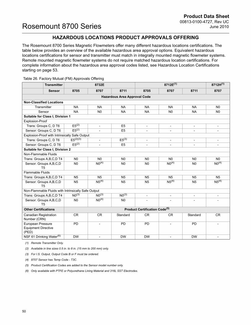
Product Data Sheet00813-0100-4727, Rev UC
June 2010Rosemount 8700 Series
50
HAZARDOUS LOCATIONS PRODUCT APPROVALS OFFERINGThe Rosemount 8700 Series Magnetic Flowmeters offer many different hazardous locations certifications. The table below provides an overview of the available hazardous area approval options. Equivalent hazardous locations certifications for sensor and transmitter must match in integrally mounted magnetic flowmeter systems. Remote mounted magnetic flowmeter systems do not require matched hazardous location certifications. For complete information about the hazardous area approval codes listed, see Hazardous Location Certifications starting on page 53.
Table 26. Factory Mutual (FM) Approvals OfferingTransmitter 8732E 8712E(1) 8712H(1)
Sensor 8705 8707 8711 8705 8707 8711 8707
Hazardous Area Approval CodeNon-Classified Locations
Transmitter NA NA NA NA NA NA N0 Sensor NA N0 NA NA N0 NA N0
Suitable for Class I, Division 1Explosion-Proof
Trans: Groups C, D T6 E5(2) - E5 - - - -Sensor: Groups C, D T6 E5(2) - E5 - - - -
Explosion-Proof with Intrinsically Safe OutputTrans: Groups C, D T6 E5(2)(3) - E5(3) - - - -
Sensor: Groups C, D T6 E5(2) - E5 - - - -Suitable for Class I, Division 2Non-Flammable FluidsTrans: Groups A,B,C,D T4 N0 N0 N0 N0 N0 N0 N0Sensor: Groups A,B,C,D
T5N0 N0(4) N0 N0 N0(4) N0 N0(4)
Flammable FluidsTrans: Groups A,B,C,D T4 N5 N5 N5 N5 N5 N5 N5Sensor: Groups A,B,C,D
T5N5 N5(4) N5 N5 N5(4) N5 N5(4)
Non-Flammable Fluids with Intrinsically Safe OutputTrans: Groups A,B,C,D T4 N0(3) N0(3) N0(3) - - - -Sensor: Groups A,B,C,D
T5N0 N0(4) N0 - - - -
Other Certifications Product Certification Code(5)
Canadian Registration Number (CRN)
CR CR Standard CR CR Standard CR
European Pressure Equipment Directive (PED)
PD - PD PD - PD -
NSF 61 Drinking Water(6) DW - DW DW - DW -
(1) Remote Transmitter Only.
(2) Available in line sizes 0.5 in. to 8 in. (15 mm to 200 mm) only.
(3) For I.S. Output, Output Code B or F must be ordered.
(4) 8707 Sensor has Temp Code - T3C.
(5) Product Certification Codes are added to the Sensor model number only.
(6) Only available with PTFE or Polyurethane Lining Material and 316L SST Electrodes.
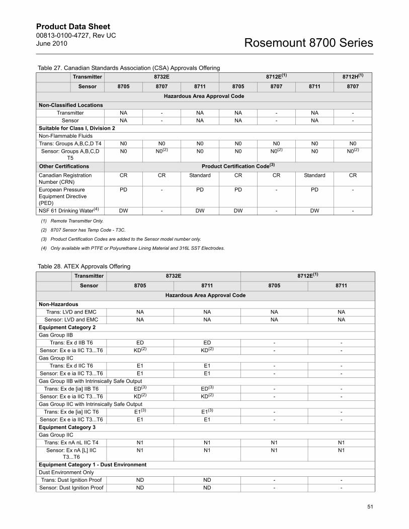
Product Data Sheet00813-0100-4727, Rev UCJune 2010
51
Rosemount 8700 Series
Table 27. Canadian Standards Association (CSA) Approvals OfferingTransmitter 8732E 8712E(1)
(1) Remote Transmitter Only.
8712H(1)
Sensor 8705 8707 8711 8705 8707 8711 8707
Hazardous Area Approval CodeNon-Classified Locations
Transmitter NA - NA NA - NA -Sensor NA - NA NA - NA -
Suitable for Class I, Division 2Non-Flammable FluidsTrans: Groups A,B,C,D T4 N0 N0 N0 N0 N0 N0 N0Sensor: Groups A,B,C,D
T5N0 N0(2)
(2) 8707 Sensor has Temp Code - T3C.
N0 N0 N0(2) N0 N0(2)
Other Certifications Product Certification Code(3)
(3) Product Certification Codes are added to the Sensor model number only.
Canadian Registration Number (CRN)
CR CR Standard CR CR Standard CR
European Pressure Equipment Directive (PED)
PD - PD PD - PD -
NSF 61 Drinking Water(4)
(4) Only available with PTFE or Polyurethane Lining Material and 316L SST Electrodes.
DW - DW DW - DW -
Table 28. ATEX Approvals OfferingTransmitter 8732E 8712E(1)
Sensor 8705 8711 8705 8711
Hazardous Area Approval CodeNon-Hazardous
Trans: LVD and EMC NA NA NA NASensor: LVD and EMC NA NA NA NA
Equipment Category 2Gas Group IIB
Trans: Ex d IIB T6 ED ED - -Sensor: Ex e ia IIC T3...T6 KD(2) KD(2) - -Gas Group IIC
Trans: Ex d IIC T6 E1 E1 - -Sensor: Ex e ia IIC T3...T6 E1 E1 - -Gas Group IIB with Intrinsically Safe Output
Trans: Ex de [ia] IIB T6 ED(3) ED(3) - -Sensor: Ex e ia IIC T3...T6 KD(2) KD(2) - -Gas Group IIC with Intrinsically Safe Output
Trans: Ex de [ia] IIC T6 E1(3) E1(3) - -Sensor: Ex e ia IIC T3...T6 E1 E1 - -Equipment Category 3Gas Group IIC
Trans: Ex nA nL IIC T4 N1 N1 N1 N1Sensor: Ex nA [L] IIC
T3...T6N1 N1 N1 N1
Equipment Category 1 - Dust EnvironmentDust Environment OnlyTrans: Dust Ignition Proof ND ND - -
Sensor: Dust Ignition Proof ND ND - -
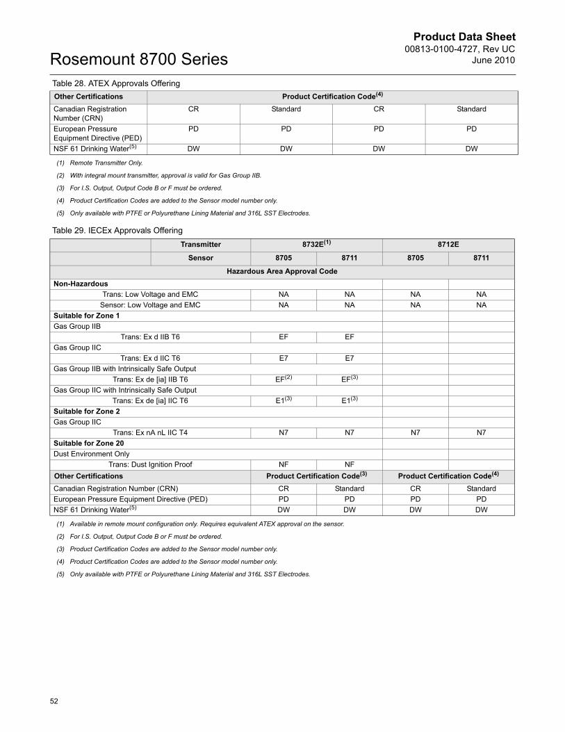
Product Data Sheet00813-0100-4727, Rev UC
June 2010Rosemount 8700 Series
52
Table 29. IECEx Approvals Offering
Other Certifications Product Certification Code(4)
Canadian Registration Number (CRN)
CR Standard CR Standard
European Pressure Equipment Directive (PED)
PD PD PD PD
NSF 61 Drinking Water(5) DW DW DW DW
(1) Remote Transmitter Only.
(2) With integral mount transmitter, approval is valid for Gas Group IIB.
(3) For I.S. Output, Output Code B or F must be ordered.
(4) Product Certification Codes are added to the Sensor model number only.
(5) Only available with PTFE or Polyurethane Lining Material and 316L SST Electrodes.
Table 28. ATEX Approvals Offering
Transmitter 8732E(1) 8712E
Sensor 8705 8711 8705 8711
Hazardous Area Approval CodeNon-Hazardous
Trans: Low Voltage and EMC NA NA NA NASensor: Low Voltage and EMC NA NA NA NA
Suitable for Zone 1Gas Group IIB
Trans: Ex d IIB T6 EF EFGas Group IIC
Trans: Ex d IIC T6 E7 E7Gas Group IIB with Intrinsically Safe Output
Trans: Ex de [ia] IIB T6 EF(2) EF(3)
Gas Group IIC with Intrinsically Safe OutputTrans: Ex de [ia] IIC T6 E1(3) E1(3)
Suitable for Zone 2Gas Group IIC
Trans: Ex nA nL IIC T4 N7 N7 N7 N7Suitable for Zone 20Dust Environment Only
Trans: Dust Ignition Proof NF NFOther Certifications Product Certification Code(3) Product Certification Code(4)
Canadian Registration Number (CRN) CR Standard CR StandardEuropean Pressure Equipment Directive (PED) PD PD PD PDNSF 61 Drinking Water(5) DW DW DW DW
(1) Available in remote mount configuration only. Requires equivalent ATEX approval on the sensor.
(2) For I.S. Output, Output Code B or F must be ordered.
(3) Product Certification Codes are added to the Sensor model number only.
(4) Product Certification Codes are added to the Sensor model number only.
(5) Only available with PTFE or Polyurethane Lining Material and 316L SST Electrodes.
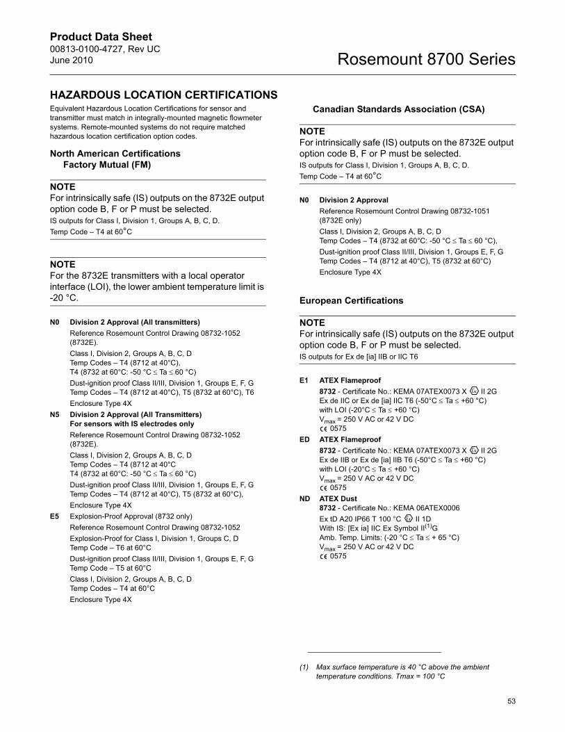
Product Data Sheet00813-0100-4727, Rev UCJune 2010
53
Rosemount 8700 Series
HAZARDOUS LOCATION CERTIFICATIONSEquivalent Hazardous Location Certifications for sensor and transmitter must match in integrally-mounted magnetic flowmeter systems. Remote-mounted systems do not require matched hazardous location certification option codes.
North American CertificationsFactory Mutual (FM)
NOTEFor intrinsically safe (IS) outputs on the 8732E output option code B, F or P must be selected.IS outputs for Class I, Division 1, Groups A, B, C, D. Temp Code – T4 at 60°C
NOTEFor the 8732E transmitters with a local operator interface (LOI), the lower ambient temperature limit is -20 °C.
N0 Division 2 Approval (All transmitters)Reference Rosemount Control Drawing 08732-1052 (8732E).Class I, Division 2, Groups A, B, C, DTemp Codes – T4 (8712 at 40°C),T4 (8732 at 60°C: -50 °C d�Ta d�60 °C) Dust-ignition proof Class II/III, Division 1, Groups E, F, GTemp Codes – T4 (8712 at 40°C), T5 (8732 at 60°C), T6 Enclosure Type 4X
N5 Division 2 Approval (All Transmitters)For sensors with IS electrodes onlyReference Rosemount Control Drawing 08732-1052 (8732E).Class I, Division 2, Groups A, B, C, DTemp Codes – T4 (8712 at 40°C T4 (8732 at 60°C: -50 °C d�Ta d�60 °C)Dust-ignition proof Class II/III, Division 1, Groups E, F, GTemp Codes – T4 (8712 at 40°C), T5 (8732 at 60°C), Enclosure Type 4X
E5 Explosion-Proof Approval (8732 only)Reference Rosemount Control Drawing 08732-1052Explosion-Proof for Class I, Division 1, Groups C, DTemp Code – T6 at 60°CDust-ignition proof Class II/III, Division 1, Groups E, F, GTemp Code – T5 at 60°CClass I, Division 2, Groups A, B, C, DTemp Codes – T4 at 60°CEnclosure Type 4X
Canadian Standards Association (CSA)
NOTEFor intrinsically safe (IS) outputs on the 8732E output option code B, F or P must be selected.IS outputs for Class I, Division 1, Groups A, B, C, D. Temp Code – T4 at 60°C
N0 Division 2 ApprovalReference Rosemount Control Drawing 08732-1051 (8732E only)Class I, Division 2, Groups A, B, C, DTemp Codes – T4 (8732 at 60°C: -50 °C d�Ta d�60 °C), Dust-ignition proof Class II/III, Division 1, Groups E, F, GTemp Codes – T4 (8712 at 40°C), T5 (8732 at 60°C)Enclosure Type 4X
European Certifications
NOTEFor intrinsically safe (IS) outputs on the 8732E output option code B, F or P must be selected.IS outputs for Ex de [ia] IIB or IIC T6
E1 ATEX Flameproof 8732 - Certificate No.: KEMA 07ATEX0073 X II 2GEx de IIC or Ex de [ia] IIC T6 (-50°C d Ta d +60 °C)with LOI (-20°C d Ta d +60 °C)Vmax = 250 V AC or 42 V DC
0575ED ATEX Flameproof
8732 - Certificate No.: KEMA 07ATEX0073 X II 2GEx de IIB or Ex de [ia] IIB T6 (-50°C d Ta d +60 °C)with LOI (-20°C d Ta d +60 °C)Vmax = 250 V AC or 42 V DC
0575ND ATEX Dust
8732 - Certificate No.: KEMA 06ATEX0006Ex tD A20 IP66 T 100 °C II 1DWith IS: [Ex ia] IIC Ex Symbol II(1)GAmb. Temp. Limits: (-20 °C d Ta d + 65 °C)Vmax = 250 V AC or 42 V DC
0575
(1) Max surface temperature is 40 °C above the ambient temperature conditions. Tmax = 100 °C
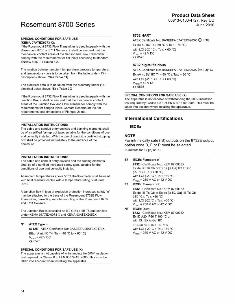
Product Data Sheet00813-0100-4727, Rev UC
June 2010Rosemount 8700 Series
54
SPECIAL CONDITIONS FOR SAFE USE (KEMA 07ATEX0073 X): If the Rosemount 8732 Flow Transmitter is used integrally with the Rosemount 8705 or 8711 Sensors, it shall be assured that the mechanical contact areas of the Sensor and Flow Transmitter comply with the requirements for flat joints according to standard EN/IEC 60079-1 clause 5.2.
The relation between ambient temperature, process temperature, and temperature class is to be taken from the table under (15 - description) above. (See Table 31)
The electrical data is to be taken from the summary under (15 - electrical data) above. (See Table 30)
If the Rosemount 8732 Flow Transmitter is used integrally with the Junction Box, it shall be assured that the mechanical contact areas of the Junction Box and Flow Transmitter comply with the requirements for flanged joints. Contact Rosemount Inc. for requirements and dimensions of Flanged Joints.
INSTALLATION INSTRUCTIONS:The cable and conduit entry devices and blanking elements shall be of a certified flameproof type, suitable for the conditions of use and correctly installed. With the use of conduit, a certified stopping box shall be provided immediately to the entrance of the enclosure.
INSTALLATION INSTRUCTIONS: The cable and conduit entry devices and the closing elements shall be of a certified increased safety type, suitable for the conditions of use and correctly installed.
At ambient temperatures above 50°C, the flow meter shall be used with heat resistant cables with a temperature rating of at least 90°C.
A Junction Box in type of explosion protection increased safety “e” may be attached to the base of the Rosemount 8732E Flow Transmitter, permitting remote mounting of the Rosemount 8705 and 8711 Sensors.
The Junction Box is classified as II 2 G Ex e IIB T6 and certified under KEMA 07ATEX0073 X and KEMA 03ATEX2052X.
N1 ATEX Type n8712E - ATEX Certificate No: BASEEFA 05ATEX0170XEEx nA nL IIC T4 (Ta = -40 °C to + 60 °C)Vmax = 42 V DC
0575
SPECIAL CONDITIONS FOR SAFE USE (X)The apparatus is not capable of withstanding the 500V insulation test required by Clause 6.8.1 EN 60079-15: 2005. This must be taken into account when installing the apparatus.
8732 HARTATEX Certificate No: BASEEFA 07ATEX0203X II 3GEx nA nL IIC T4 (-50 °C d�Ta d�+ 60 °C)with LOI (-20 °C d�Ta d�+ 60 °C)Vmax = 42 V DC
0575
8732 digital fieldbusATEX Certificate No: BASEEFA 07ATEX0203X II 3(1)GEx nA nL [ia] IIC T4 (-50 °C d�Ta d�+ 60 °C)with LOI (-20 °C d�Ta d�+ 60 °C)Vmax = 42 V DC
0575
SPECIAL CONDITIONS FOR SAFE USE (X)The apparatus is not capable of withstanding the 500V insulation test required by Clause 6.8.1 of EN 60079-15: 2005. This must be taken into account when installing the apparatus.
International CertificationsIECEx
NOTEFor intrinsically safe (IS) outputs on the 8732E output option code B, F or P must be selected.IS outputs for Ex [ia] or IIC
E7 IECEx Flameproof 8732 - Certificate No.: KEM 07.0038XEx de IIC T6 Gb or Ex de [ia Ga] IIC T6 Gb (-50 °C d Ta d +60 °C)with LOI (-20°C d Ta d +60 °C)Vmax = 250 V AC or 42 V DC
EF IECEx Flameproof8732 - Certificate No.: KEM 07.0038XEx de IIB T6 Gb or Ex de [ia IIC Ga] IIB T6 Gb (-50 °C d Ta d +60 °C)with LOI (-20°C d Ta d +60 °C)Vmax = 250 V AC or 42 V DC
NF IECEx Dust8732 - Certificate No.: KEM 07.0038XEx tD A20 IP66 T 100 °C or with IS: [Ex ia Ga] IICT6 (-50 °C d Ta d +60 °C)with LOI (-20°C d Ta d +60 °C)Vmax = 250 V AC or 42 V DC
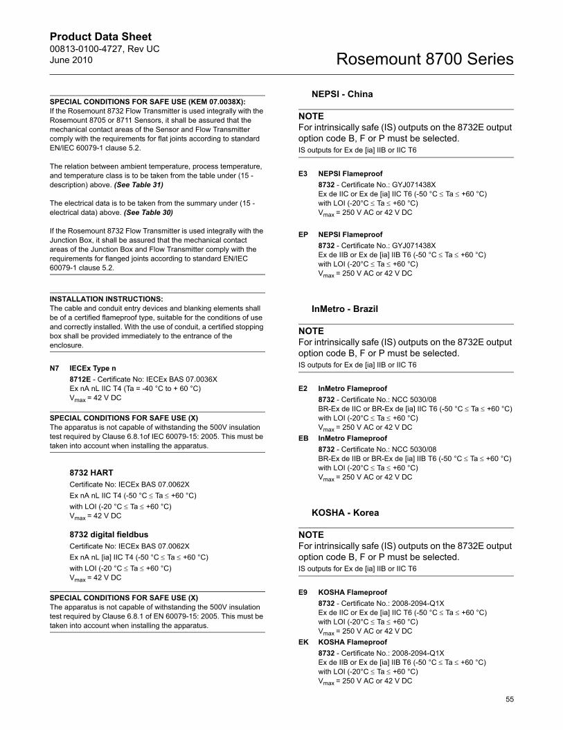
Product Data Sheet00813-0100-4727, Rev UCJune 2010
55
Rosemount 8700 Series
SPECIAL CONDITIONS FOR SAFE USE (KEM 07.0038X): If the Rosemount 8732 Flow Transmitter is used integrally with the Rosemount 8705 or 8711 Sensors, it shall be assured that the mechanical contact areas of the Sensor and Flow Transmitter comply with the requirements for flat joints according to standard EN/IEC 60079-1 clause 5.2.
The relation between ambient temperature, process temperature, and temperature class is to be taken from the table under (15 - description) above. (See Table 31)
The electrical data is to be taken from the summary under (15 - electrical data) above. (See Table 30)
If the Rosemount 8732 Flow Transmitter is used integrally with the Junction Box, it shall be assured that the mechanical contact areas of the Junction Box and Flow Transmitter comply with the requirements for flanged joints according to standard EN/IEC 60079-1 clause 5.2.
INSTALLATION INSTRUCTIONS:The cable and conduit entry devices and blanking elements shall be of a certified flameproof type, suitable for the conditions of use and correctly installed. With the use of conduit, a certified stopping box shall be provided immediately to the entrance of the enclosure.
N7 IECEx Type n8712E - Certificate No: IECEx BAS 07.0036XEx nA nL IIC T4 (Ta = -40 °C to + 60 °C)Vmax = 42 V DC
SPECIAL CONDITIONS FOR SAFE USE (X)The apparatus is not capable of withstanding the 500V insulation test required by Clause 6.8.1of IEC 60079-15: 2005. This must be taken into account when installing the apparatus.
8732 HARTCertificate No: IECEx BAS 07.0062XEx nA nL IIC T4 (-50 °C d Ta d +60 °C)with LOI (-20 °C d Ta d +60 °C)Vmax = 42 V DC
8732 digital fieldbusCertificate No: IECEx BAS 07.0062XEx nA nL [ia] IIC T4 (-50 °C d Ta d +60 °C)with LOI (-20 °C d Ta d +60 °C)Vmax = 42 V DC
SPECIAL CONDITIONS FOR SAFE USE (X)The apparatus is not capable of withstanding the 500V insulation test required by Clause 6.8.1 of EN 60079-15: 2005. This must be taken into account when installing the apparatus.
NEPSI - China
NOTEFor intrinsically safe (IS) outputs on the 8732E output option code B, F or P must be selected.IS outputs for Ex de [ia] IIB or IIC T6
E3 NEPSI Flameproof 8732 - Certificate No.: GYJ071438XEx de IIC or Ex de [ia] IIC T6 (-50 °C d Ta d +60 °C)with LOI (-20°C d Ta d +60 °C)Vmax = 250 V AC or 42 V DC
EP NEPSI Flameproof8732 - Certificate No.: GYJ071438XEx de IIB or Ex de [ia] IIB T6 (-50 °C d Ta d +60 °C)with LOI (-20°C d Ta d +60 °C)Vmax = 250 V AC or 42 V DC
InMetro - Brazil
NOTEFor intrinsically safe (IS) outputs on the 8732E output option code B, F or P must be selected.IS outputs for Ex de [ia] IIB or IIC T6
E2 InMetro Flameproof 8732 - Certificate No.: NCC 5030/08BR-Ex de IIC or BR-Ex de [ia] IIC T6 (-50 °C d Ta d +60 °C)with LOI (-20°C d Ta d +60 °C)Vmax = 250 V AC or 42 V DC
EB InMetro Flameproof8732 - Certificate No.: NCC 5030/08BR-Ex de IIB or BR-Ex de [ia] IIB T6 (-50 °C d Ta d +60 °C)with LOI (-20°C d Ta d +60 °C)Vmax = 250 V AC or 42 V DC
KOSHA - Korea
NOTEFor intrinsically safe (IS) outputs on the 8732E output option code B, F or P must be selected.IS outputs for Ex de [ia] IIB or IIC T6
E9 KOSHA Flameproof 8732 - Certificate No.: 2008-2094-Q1XEx de IIC or Ex de [ia] IIC T6 (-50 °C d Ta d +60 °C)with LOI (-20°C d Ta d +60 °C)Vmax = 250 V AC or 42 V DC
EK KOSHA Flameproof8732 - Certificate No.: 2008-2094-Q1XEx de IIB or Ex de [ia] IIB T6 (-50 °C d Ta d +60 °C)with LOI (-20°C d Ta d +60 °C)Vmax = 250 V AC or 42 V DC
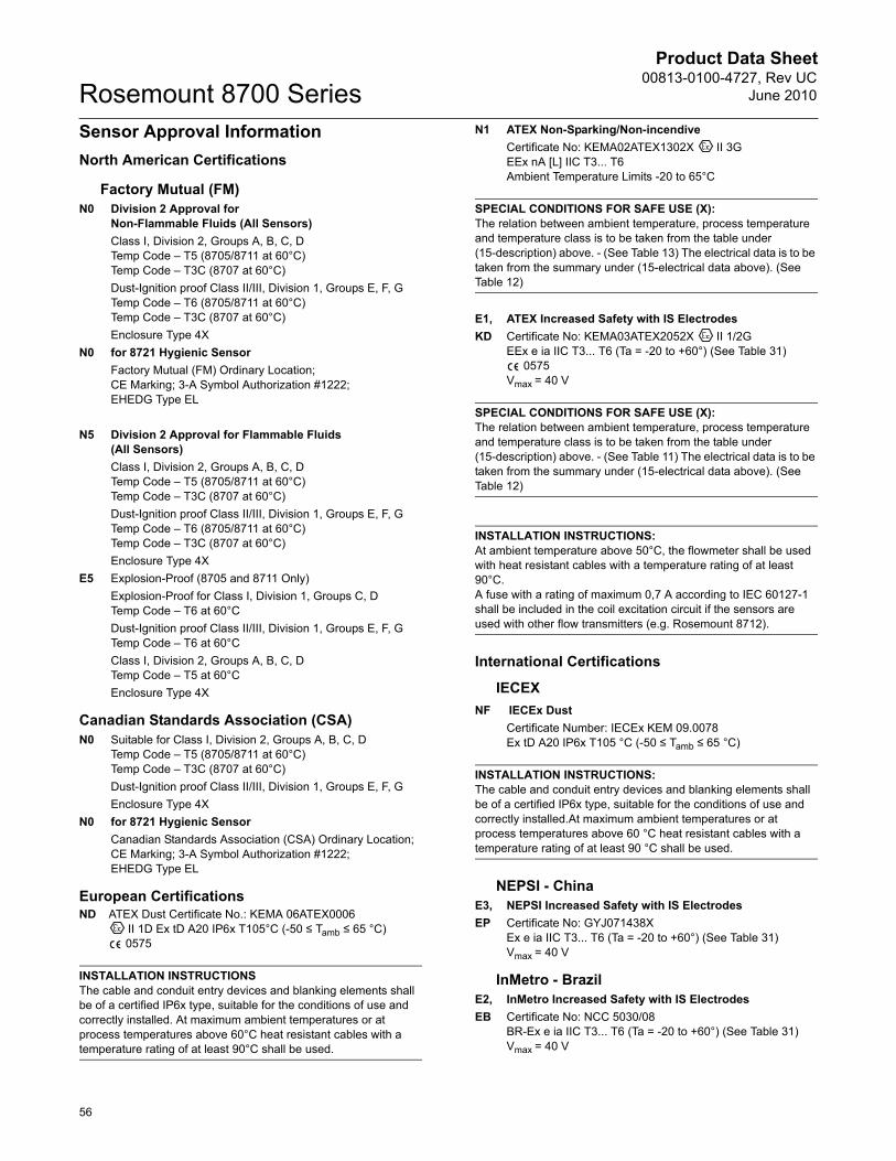
Product Data Sheet00813-0100-4727, Rev UC
June 2010Rosemount 8700 Series
56
Sensor Approval InformationNorth American Certifications
Factory Mutual (FM)N0 Division 2 Approval for
Non-Flammable Fluids (All Sensors)Class I, Division 2, Groups A, B, C, DTemp Code – T5 (8705/8711 at 60°C)Temp Code – T3C (8707 at 60°C)Dust-Ignition proof Class II/III, Division 1, Groups E, F, GTemp Code – T6 (8705/8711 at 60°C)Temp Code – T3C (8707 at 60°C)Enclosure Type 4X
N0 for 8721 Hygienic SensorFactory Mutual (FM) Ordinary Location; CE Marking; 3-A Symbol Authorization #1222;EHEDG Type EL
N5 Division 2 Approval for Flammable Fluids(All Sensors)Class I, Division 2, Groups A, B, C, DTemp Code – T5 (8705/8711 at 60°C)Temp Code – T3C (8707 at 60°C)Dust-Ignition proof Class II/III, Division 1, Groups E, F, GTemp Code – T6 (8705/8711 at 60°C)Temp Code – T3C (8707 at 60°C)Enclosure Type 4X
E5 Explosion-Proof (8705 and 8711 Only)Explosion-Proof for Class I, Division 1, Groups C, DTemp Code – T6 at 60°CDust-Ignition proof Class II/III, Division 1, Groups E, F, GTemp Code – T6 at 60°CClass I, Division 2, Groups A, B, C, DTemp Code – T5 at 60°CEnclosure Type 4X
Canadian Standards Association (CSA)N0 Suitable for Class I, Division 2, Groups A, B, C, D
Temp Code – T5 (8705/8711 at 60°C)Temp Code – T3C (8707 at 60°C)Dust-Ignition proof Class II/III, Division 1, Groups E, F, GEnclosure Type 4X
N0 for 8721 Hygienic SensorCanadian Standards Association (CSA) Ordinary Location;CE Marking; 3-A Symbol Authorization #1222;EHEDG Type EL
European CertificationsND ATEX Dust Certificate No.: KEMA 06ATEX0006
II 1D Ex tD A20 IP6x T105°C (-50 ≤ Tamb ≤ 65 °C) 0575
INSTALLATION INSTRUCTIONSThe cable and conduit entry devices and blanking elements shall be of a certified IP6x type, suitable for the conditions of use and correctly installed. At maximum ambient temperatures or at process temperatures above 60°C heat resistant cables with a temperature rating of at least 90°C shall be used.
N1 ATEX Non-Sparking/Non-incendiveCertificate No: KEMA02ATEX1302X II 3GEEx nA [L] IIC T3... T6Ambient Temperature Limits -20 to 65°C
SPECIAL CONDITIONS FOR SAFE USE (X):The relation between ambient temperature, process temperature and temperature class is to be taken from the table under (15-description) above. - (See Table 13) The electrical data is to be taken from the summary under (15-electrical data above). (See Table 12)
E1, ATEX Increased Safety with IS ElectrodesKD Certificate No: KEMA03ATEX2052X II 1/2G
EEx e ia IIC T3... T6 (Ta = -20 to +60°) (See Table 31) 0575
Vmax = 40 V
SPECIAL CONDITIONS FOR SAFE USE (X):The relation between ambient temperature, process temperature and temperature class is to be taken from the table under (15-description) above. - (See Table 11) The electrical data is to be taken from the summary under (15-electrical data above). (See Table 12)
INSTALLATION INSTRUCTIONS:At ambient temperature above 50°C, the flowmeter shall be used with heat resistant cables with a temperature rating of at least 90°C.A fuse with a rating of maximum 0,7 A according to IEC 60127-1 shall be included in the coil excitation circuit if the sensors are used with other flow transmitters (e.g. Rosemount 8712).
International Certifications
IECEXNF IECEx Dust
Certificate Number: IECEx KEM 09.0078Ex tD A20 IP6x T105 °C (-50 ≤ Tamb ≤ 65 °C)
INSTALLATION INSTRUCTIONS:The cable and conduit entry devices and blanking elements shall be of a certified IP6x type, suitable for the conditions of use and correctly installed.At maximum ambient temperatures or at process temperatures above 60 °C heat resistant cables with a temperature rating of at least 90 °C shall be used.
NEPSI - ChinaE3, NEPSI Increased Safety with IS ElectrodesEP Certificate No: GYJ071438X
Ex e ia IIC T3... T6 (Ta = -20 to +60°) (See Table 31)Vmax = 40 V
InMetro - BrazilE2, InMetro Increased Safety with IS ElectrodesEB Certificate No: NCC 5030/08
BR-Ex e ia IIC T3... T6 (Ta = -20 to +60°) (See Table 31)Vmax = 40 V
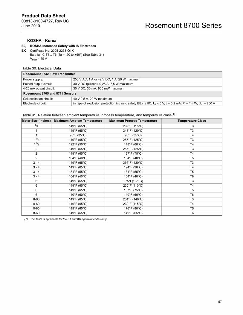
Product Data Sheet00813-0100-4727, Rev UCJune 2010
57
Rosemount 8700 Series
KOSHA - KoreaE9, KOSHA Increased Safety with IS ElectrodesEK Certificate No: 2005-2233-Q1X
Ex e ia IIC T3... T6 (Ta = -20 to +60°) (See Table 31)Vmax = 40 V
Table 30. Electrical DataRosemount 8732 Flow TransmitterPower supply: 250 V AC, 1 A or 42 V DC, 1 A, 20 W maximumPulsed output circuit: 30 V DC (pulsed), 0,25 A, 7,5 W maximum4-20 mA output circuit: 30 V DC, 30 mA, 900 mW maximumRosemount 8705 and 8711 SensorsCoil excitation circuit: 40 V 0,5 A, 20 W maximumElectrode circuit: in type of explosion protection intrinsic safety EEx ia IIC, Ui = 5 V, li = 0.2 mA, Pi = 1 mW, Um = 250 V
Table 31. Relation between ambient temperature, process temperature, and temperature class(1)
Meter Size (Inches) Maximum Ambient Temperature Maximum Process Temperature Temperature Class1/2 149°F (65°C) 239°F (115°C) T31 149°F (65°C) 248°F (120°C) T31 95°F (35°C) 95°F (35°C) T4
11/2 149°F (65°C) 257°F (125°C) T311/2 122°F (50°C) 148°F (60°C) T42 149°F (65°C) 257°F (125°C) T32 149°F (65°C) 167°F (75°C) T42 104°F (40°C) 104°F (40°C) T5
3 - 4 149°F (65°C) 266°F (130°C) T33 - 4 149°F (65°C) 194°F (90°C) T43 - 4 131°F (55°C) 131°F (55°C) T53 - 4 104°F (40°C) 104°F (40°C) T6
6 149°F (65°C) 275°F(135°C) T36 149°F (65°C) 230°F (110°C) T46 149°F (65°C) 167°F (75°C) T56 140°F (60°C) 140°F (60°C) T6
8-60 149°F (65°C) 284°F (140°C) T38-60 149°F (65°C) 239°F (115°C) T48-60 149°F (65°C) 176°F (80°C) T58-60 149°F (65°C) 149°F (65°C) T6
(1) This table is applicable for the E1 and KD approval codes only.
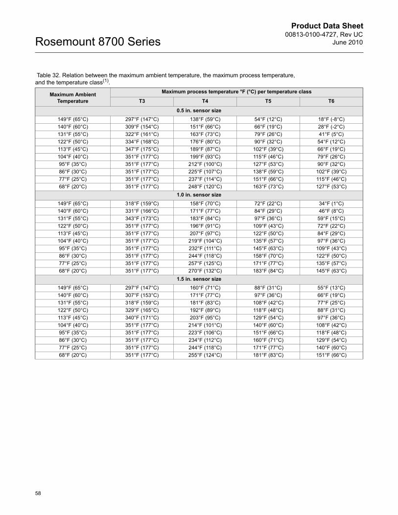
Product Data Sheet00813-0100-4727, Rev UC
June 2010Rosemount 8700 Series
58
Table 32. Relation between the maximum ambient temperature, the maximum process temperature, and the temperature class(1).
Maximum Ambient Temperature
Maximum process temperature °F (°C) per temperature class
T3 T4 T5 T6
0.5 in. sensor size149°F (65°C) 297°F (147°C) 138°F (59°C) 54°F (12°C) 18°F (-8°C)140°F (60°C) 309°F (154°C) 151°F (66°C) 66°F (19°C) 28°F (-2°C)131°F (55°C) 322°F (161°C) 163°F (73°C) 79°F (26°C) 41°F (5°C)122°F (50°C) 334°F (168°C) 176°F (80°C) 90°F (32°C) 54°F (12°C)113°F (45°C) 347°F (175°C) 189°F (87°C) 102°F (39°C) 66°F (19°C)104°F (40°C) 351°F (177°C) 199°F (93°C) 115°F (46°C) 79°F (26°C)95°F (35°C) 351°F (177°C) 212°F (100°C) 127°F (53°C) 90°F (32°C)86°F (30°C) 351°F (177°C) 225°F (107°C) 138°F (59°C) 102°F (39°C)77°F (25°C) 351°F (177°C) 237°F (114°C) 151°F (66°C) 115°F (46°C)68°F (20°C) 351°F (177°C) 248°F (120°C) 163°F (73°C) 127°F (53°C)
1.0 in. sensor size149°F (65°C) 318°F (159°C) 158°F (70°C) 72°F (22°C) 34°F (1°C)140°F (60°C) 331°F (166°C) 171°F (77°C) 84°F (29°C) 46°F (8°C)131°F (55°C) 343°F (173°C) 183°F (84°C) 97°F (36°C) 59°F (15°C)122°F (50°C) 351°F (177°C) 196°F (91°C) 109°F (43°C) 72°F (22°C)113°F (45°C) 351°F (177°C) 207°F (97°C) 122°F (50°C) 84°F (29°C)104°F (40°C) 351°F (177°C) 219°F (104°C) 135°F (57°C) 97°F (36°C)95°F (35°C) 351°F (177°C) 232°F (111°C) 145°F (63°C) 109°F (43°C)86°F (30°C) 351°F (177°C) 244°F (118°C) 158°F (70°C) 122°F (50°C)77°F (25°C) 351°F (177°C) 257°F (125°C) 171°F (77°C) 135°F (57°C)68°F (20°C) 351°F (177°C) 270°F (132°C) 183°F (84°C) 145°F (63°C)
1.5 in. sensor size149°F (65°C) 297°F (147°C) 160°F (71°C) 88°F (31°C) 55°F (13°C)140°F (60°C) 307°F (153°C) 171°F (77°C) 97°F (36°C) 66°F (19°C)131°F (55°C) 318°F (159°C) 181°F (83°C) 108°F (42°C) 77°F (25°C)122°F (50°C) 329°F (165°C) 192°F (89°C) 118°F (48°C) 88°F (31°C)113°F (45°C) 340°F (171°C) 203°F (95°C) 129°F (54°C) 97°F (36°C)104°F (40°C) 351°F (177°C) 214°F (101°C) 140°F (60°C) 108°F (42°C)95°F (35°C) 351°F (177°C) 223°F (106°C) 151°F (66°C) 118°F (48°C)86°F (30°C) 351°F (177°C) 234°F (112°C) 160°F (71°C) 129°F (54°C)77°F (25°C) 351°F (177°C) 244°F (118°C) 171°F (77°C) 140°F (60°C)68°F (20°C) 351°F (177°C) 255°F (124°C) 181°F (83°C) 151°F (66°C)
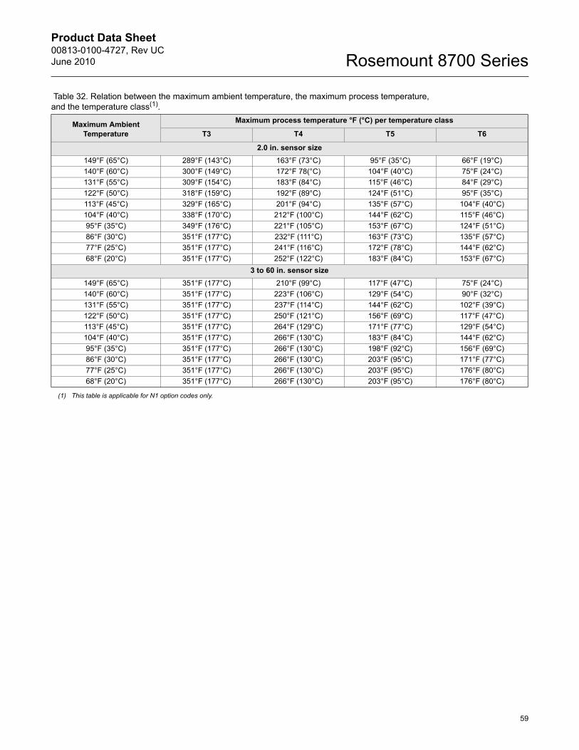
Product Data Sheet00813-0100-4727, Rev UCJune 2010
59
Rosemount 8700 Series
2.0 in. sensor size149°F (65°C) 289°F (143°C) 163°F (73°C) 95°F (35°C) 66°F (19°C)140°F (60°C) 300°F (149°C) 172°F 78(°C) 104°F (40°C) 75°F (24°C)131°F (55°C) 309°F (154°C) 183°F (84°C) 115°F (46°C) 84°F (29°C)122°F (50°C) 318°F (159°C) 192°F (89°C) 124°F (51°C) 95°F (35°C)113°F (45°C) 329°F (165°C) 201°F (94°C) 135°F (57°C) 104°F (40°C)104°F (40°C) 338°F (170°C) 212°F (100°C) 144°F (62°C) 115°F (46°C)95°F (35°C) 349°F (176°C) 221°F (105°C) 153°F (67°C) 124°F (51°C)86°F (30°C) 351°F (177°C) 232°F (111°C) 163°F (73°C) 135°F (57°C)77°F (25°C) 351°F (177°C) 241°F (116°C) 172°F (78°C) 144°F (62°C)68°F (20°C) 351°F (177°C) 252°F (122°C) 183°F (84°C) 153°F (67°C)
3 to 60 in. sensor size149°F (65°C) 351°F (177°C) 210°F (99°C) 117°F (47°C) 75°F (24°C)140°F (60°C) 351°F (177°C) 223°F (106°C) 129°F (54°C) 90°F (32°C)131°F (55°C) 351°F (177°C) 237°F (114°C) 144°F (62°C) 102°F (39°C)122°F (50°C) 351°F (177°C) 250°F (121°C) 156°F (69°C) 117°F (47°C)113°F (45°C) 351°F (177°C) 264°F (129°C) 171°F (77°C) 129°F (54°C)104°F (40°C) 351°F (177°C) 266°F (130°C) 183°F (84°C) 144°F (62°C)95°F (35°C) 351°F (177°C) 266°F (130°C) 198°F (92°C) 156°F (69°C)86°F (30°C) 351°F (177°C) 266°F (130°C) 203°F (95°C) 171°F (77°C)77°F (25°C) 351°F (177°C) 266°F (130°C) 203°F (95°C) 176°F (80°C)68°F (20°C) 351°F (177°C) 266°F (130°C) 203°F (95°C) 176°F (80°C)
(1) This table is applicable for N1 option codes only.
Table 32. Relation between the maximum ambient temperature, the maximum process temperature, and the temperature class(1).
Maximum Ambient Temperature
Maximum process temperature °F (°C) per temperature class
T3 T4 T5 T6
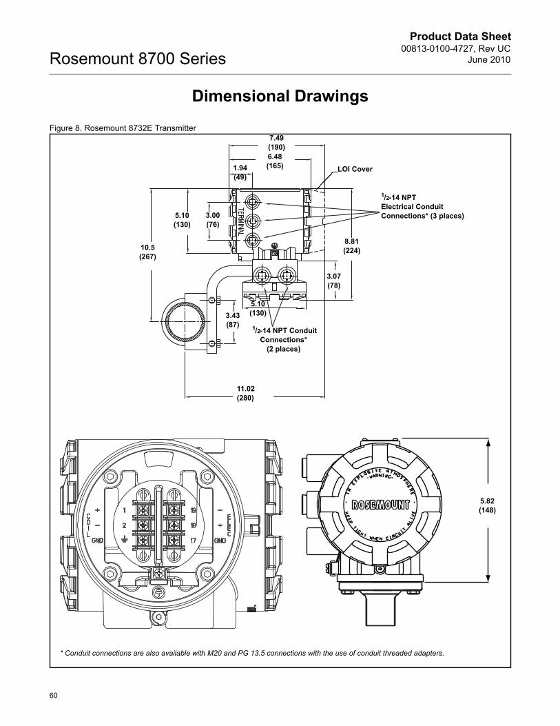
Product Data Sheet00813-0100-4727, Rev UC
June 2010Rosemount 8700 Series
60
Dimensional Drawings
Figure 8. Rosemount 8732E Transmitter
1/2-14 NPT Electrical Conduit Connections* (3 places)
LOI Cover
11.02(280)
1/2-14 NPT Conduit Connections*
(2 places)
10.5(267)
5.10(130)
5.10(130)
7.49(190)6.48(165)1.94
(49)
8.81(224)
3.07(78)
3.00(76)
3.43(87)
5.82(148)
* Conduit connections are also available with M20 and PG 13.5 connections with the use of conduit threaded adapters.
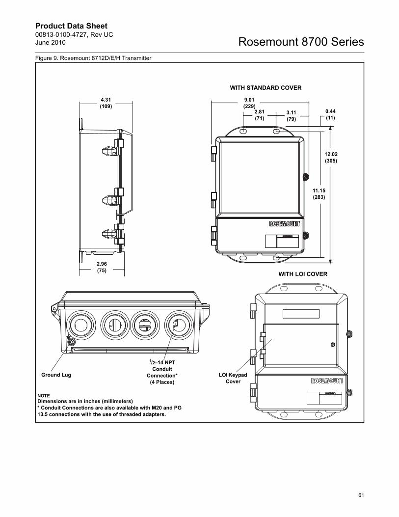
Product Data Sheet00813-0100-4727, Rev UCJune 2010
61
Rosemount 8700 SeriesFigure 9. Rosemount 8712D/E/H Transmitter
4.31(109)
LOI Keypad Cover
9.01(229)
11.15(283)
2.81(71)
3.11(79)
12.02(305)
0.44(11)
Ground Lug
1/2–14 NPTConduit
Connection* (4 Places)
WITH STANDARD COVER
NOTEDimensions are in inches (millimeters)* Conduit Connections are also available with M20 and PG 13.5 connections with the use of threaded adapters.
2.96(75) WITH LOI COVER
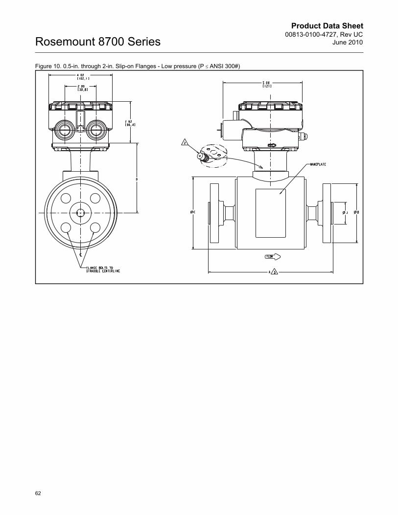
Product Data Sheet00813-0100-4727, Rev UC
June 2010Rosemount 8700 Series
62
Figure 10. 0.5-in. through 2-in. Slip-on Flanges - Low pressure (P d�ANSI 300#)
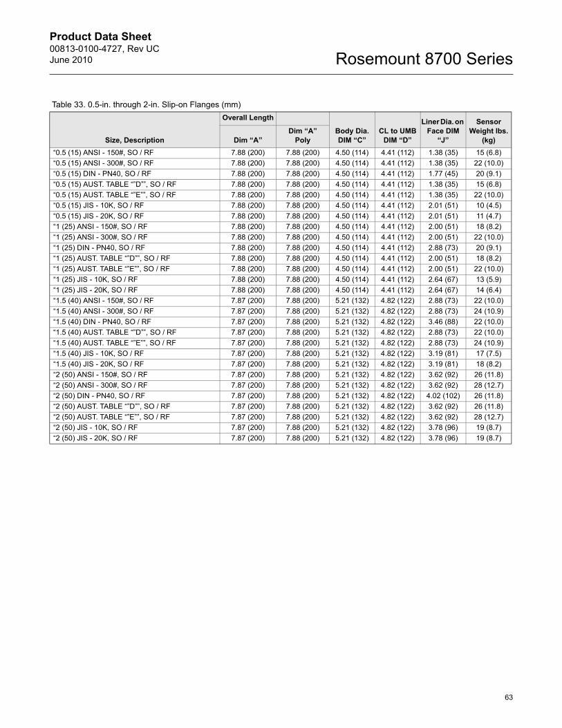
Product Data Sheet00813-0100-4727, Rev UCJune 2010
63
Rosemount 8700 Series
Table 33. 0.5-in. through 2-in. Slip-on Flanges (mm)
Size, Description
Overall Length
Body Dia. DIM “C”
CL to UMB DIM “D”
Liner Dia. on Face DIM
“J”
Sensor Weight lbs.
(kg)Dim “A”Dim “A”
Poly“0.5 (15) ANSI - 150#, SO / RF 7.88 (200) 7.88 (200) 4.50 (114) 4.41 (112) 1.38 (35) 15 (6.8)“0.5 (15) ANSI - 300#, SO / RF 7.88 (200) 7.88 (200) 4.50 (114) 4.41 (112) 1.38 (35) 22 (10.0)“0.5 (15) DIN - PN40, SO / RF 7.88 (200) 7.88 (200) 4.50 (114) 4.41 (112) 1.77 (45) 20 (9.1)“0.5 (15) AUST. TABLE “”D””, SO / RF 7.88 (200) 7.88 (200) 4.50 (114) 4.41 (112) 1.38 (35) 15 (6.8)“0.5 (15) AUST. TABLE “”E””, SO / RF 7.88 (200) 7.88 (200) 4.50 (114) 4.41 (112) 1.38 (35) 22 (10.0)“0.5 (15) JIS - 10K, SO / RF 7.88 (200) 7.88 (200) 4.50 (114) 4.41 (112) 2.01 (51) 10 (4.5)“0.5 (15) JIS - 20K, SO / RF 7.88 (200) 7.88 (200) 4.50 (114) 4.41 (112) 2.01 (51) 11 (4.7)“1 (25) ANSI - 150#, SO / RF 7.88 (200) 7.88 (200) 4.50 (114) 4.41 (112) 2.00 (51) 18 (8.2)“1 (25) ANSI - 300#, SO / RF 7.88 (200) 7.88 (200) 4.50 (114) 4.41 (112) 2.00 (51) 22 (10.0)“1 (25) DIN - PN40, SO / RF 7.88 (200) 7.88 (200) 4.50 (114) 4.41 (112) 2.88 (73) 20 (9.1)“1 (25) AUST. TABLE “”D””, SO / RF 7.88 (200) 7.88 (200) 4.50 (114) 4.41 (112) 2.00 (51) 18 (8.2)“1 (25) AUST. TABLE “”E””, SO / RF 7.88 (200) 7.88 (200) 4.50 (114) 4.41 (112) 2.00 (51) 22 (10.0)“1 (25) JIS - 10K, SO / RF 7.88 (200) 7.88 (200) 4.50 (114) 4.41 (112) 2.64 (67) 13 (5.9)“1 (25) JIS - 20K, SO / RF 7.88 (200) 7.88 (200) 4.50 (114) 4.41 (112) 2.64 (67) 14 (6.4)“1.5 (40) ANSI - 150#, SO / RF 7.87 (200) 7.88 (200) 5.21 (132) 4.82 (122) 2.88 (73) 22 (10.0)“1.5 (40) ANSI - 300#, SO / RF 7.87 (200) 7.88 (200) 5.21 (132) 4.82 (122) 2.88 (73) 24 (10.9)“1.5 (40) DIN - PN40, SO / RF 7.87 (200) 7.88 (200) 5.21 (132) 4.82 (122) 3.46 (88) 22 (10.0)“1.5 (40) AUST. TABLE “”D””, SO / RF 7.87 (200) 7.88 (200) 5.21 (132) 4.82 (122) 2.88 (73) 22 (10.0)“1.5 (40) AUST. TABLE “”E””, SO / RF 7.87 (200) 7.88 (200) 5.21 (132) 4.82 (122) 2.88 (73) 24 (10.9)“1.5 (40) JIS - 10K, SO / RF 7.87 (200) 7.88 (200) 5.21 (132) 4.82 (122) 3.19 (81) 17 (7.5)“1.5 (40) JIS - 20K, SO / RF 7.87 (200) 7.88 (200) 5.21 (132) 4.82 (122) 3.19 (81) 18 (8.2)“2 (50) ANSI - 150#, SO / RF 7.87 (200) 7.88 (200) 5.21 (132) 4.82 (122) 3.62 (92) 26 (11.8)“2 (50) ANSI - 300#, SO / RF 7.87 (200) 7.88 (200) 5.21 (132) 4.82 (122) 3.62 (92) 28 (12.7)“2 (50) DIN - PN40, SO / RF 7.87 (200) 7.88 (200) 5.21 (132) 4.82 (122) 4.02 (102) 26 (11.8)“2 (50) AUST. TABLE “”D””, SO / RF 7.87 (200) 7.88 (200) 5.21 (132) 4.82 (122) 3.62 (92) 26 (11.8)“2 (50) AUST. TABLE “”E””, SO / RF 7.87 (200) 7.88 (200) 5.21 (132) 4.82 (122) 3.62 (92) 28 (12.7)“2 (50) JIS - 10K, SO / RF 7.87 (200) 7.88 (200) 5.21 (132) 4.82 (122) 3.78 (96) 19 (8.7)“2 (50) JIS - 20K, SO / RF 7.87 (200) 7.88 (200) 5.21 (132) 4.82 (122) 3.78 (96) 19 (8.7)
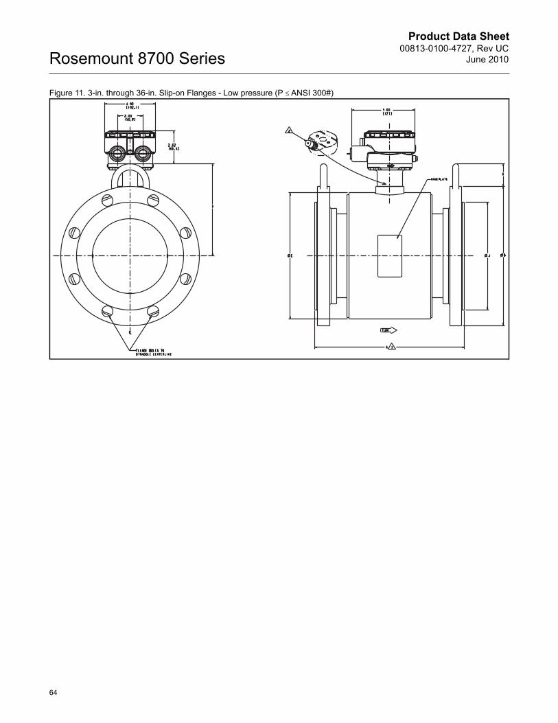
Product Data Sheet00813-0100-4727, Rev UC
June 2010Rosemount 8700 Series
64
Figure 11. 3-in. through 36-in. Slip-on Flanges - Low pressure (P d�ANSI 300#)
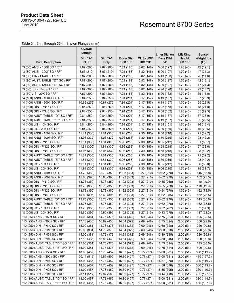
Product Data Sheet00813-0100-4727, Rev UCJune 2010
65
Rosemount 8700 Series
Table 34. 3-in. through 36-in. Slip-on Flanges (mm)
Size, Description
Overall Length
Dim “A”Poly
Body Dia. DIM “C”
CL to UMB DIM “D”
Liner Dia. on Face DIM
“J”
Lift Ring Height
DIM “K”
Sensor Weight lbs.
(kg)Dim “A”
PTFE“3 (80) ANSI - 150# SO / RF” 7.87 (200) 7.87 (200) 7.21 (183) 5.82 (148) 5.00 (127) 1.70 (43) 42 (19.1)“3 (80) ANSI - 300# SO / RF” 8.63 (219) 8.63 (219) 7.21 (183) 5.82 (148) 5.00 (127) 1.70 (43) 47 (21.3)“3 (80) DIN - PN40 SO / RF” 7.87 (200) 7.87 (200) 7.21 (183) 5.82 (148) 5.43 (138) 1.70 (43) 26 (11.8)“3 (80) AUST. TABLE “”D”” SO / RF” 7.87 (200) 7.87 (200) 7.21 (183) 5.82 (148) 5.00 (127) 1.70 (43) 42 (19.1)“3 (80) AUST. TABLE “”E”” SO / RF” 7.87 (200) 7.87 (200) 7.21 (183) 5.82 (148) 5.00 (127) 1.70 (43) 47 (21.3)“3 (80) JIS - 10K SO / RF” 7.87 (200) 7.87 (200) 7.21 (183) 5.82 (148) 4.96 (126) 1.70 (43) 29 (13.2)“3 (80) JIS - 20K SO / RF” 7.87 (200) 7.87 (200) 7.21 (183) 5.82 (148) 5.20 (132) 1.70 (43) 35 (16.0)“4 (100) ANSI - 150# SO / RF” 9.84 (250) 9.84 (250) 7.91 (201) 6.17 (157) 6.19 (157) 1.70 (43) 57 (25.9)“4 (100) ANSI - 300# SO / RF” 10.88 (276) 10.87 (276) 7.91 (201) 6.17 (157) 6.19 (157) 1.70 (43) 65 (29.5)“4 (100) DIN - PN16 SO / RF” 9.84 (250) 9.84 (250) 7.91 (201) 6.17 (157) 6.22 (158) 1.70 (43) 48 (21.8)“4 (100) DIN - PN40 SO / RF” 9.84 (250) 9.84 (250) 7.91 (201) 6.17 (157) 6.38 (162) 1.70 (43) 65 (29.5)“4 (100) AUST. TABLE “”D”” SO / RF” 9.84 (250) 9.84 (250) 7.91 (201) 6.17 (157) 6.19 (157) 1.70 (43) 57 (25.9)“4 (100) AUST. TABLE “”E”” SO / RF” 9.84 (250) 9.84 (250) 7.91 (201) 6.17 (157) 6.19 (157) 1.70 (43) 65 (29.5)“4 (100) JIS - 10K SO / RF” 9.84 (250) 9.84 (250) 7.91 (201) 6.17 (157) 5.95 (151) 1.70 (43) 36 (16.4)“4 (100) JIS - 20K SO / RF” 9.84 (250) 9.84 (250) 7.91 (201) 6.17 (157) 6.30 (160) 1.70 (43) 45 (20.6)“6 (150) ANSI - 150# SO / RF” 11.81 (300) 11.81 (300) 9.98 (253) 7.30 (185) 8.50 (216) 1.70 (43) 71 (32.2)“6 (150) ANSI - 300# SO / RF” 13.06 (332) 13.06 (332) 9.98 (253) 7.30 (185) 8.50 (216) 1.70 (43) 93 (42.2)“6 (150) DIN - PN16 SO / RF” 11.81 (300) 11.81 (300) 9.98 (253) 7.30 (185) 8.35 (212) 1.70 (43) 81 (36.7)“6 (150) DIN - PN25 SO / RF” 11.81 (300) 11.81 (300) 9.98 (253) 7.30 (185) 8.58 (218) 1.70 (43) 87 (39.6)“6 (150) DIN - PN40 SO / RF” 13.06 (332) 13.06 (332) 9.98 (253) 7.30 (185) 8.58 (218) 1.70 (43) 93 (42.2)“6 (150) AUST. TABLE “”D”” SO / RF” 11.81 (300) 11.81 (300) 9.98 (253) 7.30 (185) 8.50 (216) 1.70 (43) 71 (32.2)“6 (150) AUST. TABLE “”E”” SO / RF” 11.81 (300) 11.81 (300) 9.98 (253) 7.30 (185) 8.50 (216) 1.70 (43) 93 (42.2)“6 (150) JIS - 10K SO / RF” 11.81 (300) 11.81 (300) 9.98 (253) 7.30 (185) 8.35 (212) 1.70 (43) 66 (30.0)“6 (150) JIS - 20K SO / RF” 11.81 (300) 11.81 (300) 9.98 (253) 7.30 (185) 9.06 (230) 1.70 (43) 85 (38.7)“8 (200) ANSI - 150# SO / RF” 13.78 (350) 13.78 (350) 11.92 (303) 8.27 (210) 10.62 (270) 1.70 (43) 145 (65.8)“8 (200) ANSI - 300# SO / RF” 15.60 (396) 15.60 (396) 11.92 (303) 8.27 (210) 10.62 (270) 1.70 (43) 162 (73.5)“8 (200) DIN - PN10 SO / RF” 13.78 (350) 13.78 (350) 11.92 (303) 8.27 (210) 10.55 (268) 1.70 (43) 110 (49.9)“8 (200) DIN - PN16 SO / RF” 13.78 (350) 13.78 (350) 11.92 (303) 8.27 (210) 10.55 (268) 1.70 (43) 110 (49.9)“8 (200) DIN - PN25 SO / RF” 13.78 (350) 13.78 (350) 11.92 (303) 8.27 (210) 10.94 (278) 1.70 (43) 162 (73.5)“8 (200) DIN - PN40 SO / RF” 15.60 (396) 15.60 (396) 11.92 (303) 8.27 (210) 11.22 (285) 1.70 (43) 162 (73.5)“8 (200) AUST. TABLE “”D”” SO / RF” 13.78 (350) 13.78 (350) 11.92 (303) 8.27 (210) 10.62 (270) 1.70 (43) 145 (65.8)“8 (200) AUST. TABLE “”E”” SO / RF” 13.78 (350) 13.78 (350) 11.92 (303) 8.27 (210) 10.62 (270) 1.70 (43) 162 (73.5)“8 (200) JIS - 10K SO / RF” 13.78 (350) 13.78 (350) 11.92 (303) 8.27 (210) 10.32 (262) 1.70 (43) 82 (37.3)“8 (200) JIS - 20K SO / RF” 15.60 (396) 15.60 (396) 11.92 (303) 8.27 (210) 10.83 (275) 1.70 (43) 137 (62.3)“10 (250) ANSI - 150# SO / RF” 15.00 (381) 14.76 (376) 14.64 (372) 9.69 (246) 12.75 (324) 2.00 (51) 195 (88.5)“10 (250) ANSI - 300# SO / RF” 17.13 (435) 16.89 (430) 14.64 (372) 9.69 (246) 12.75 (324) 2.00 (51) 300 (99.8)“10 (250) DIN - PN10 SO / RF” 15.00 (381) 14.76 (376) 14.64 (372) 9.69 (246) 12.60 (320) 2.00 (51) 220 (99.8)“10 (250) DIN - PN16 SO / RF” 15.00 (381) 14.76 (376) 14.64 (372) 9.69 (246) 12.60 (320) 2.00 (51) 220 (99.8)“10 (250) DIN - PN25 SO / RF” 15.00 (381) 14.76 (376) 14.64 (372) 9.69 (246) 13.19 (335) 2.00 (51) 220 (99.8)“10 (250) DIN - PN40 SO / RF” 17.13 (435) 16.89 (430) 14.64 (372) 9.69 (246) 13.58 (345) 2.00 (51) 300 (99.8)“10 (250) AUST. TABLE “”D”” SO / RF” 15.00 (381) 14.76 (376) 14.64 (372) 9.69 (246) 12.75 (324) 2.00 (51) 195 (88.5)“10 (250) AUST. TABLE “”E”” SO / RF” 15.00 (381) 14.76 (376) 14.64 (372) 9.69 (246) 12.75 (324) 2.00 (51) 300 (99.8)“12 (300) ANSI - 150# SO / RF” 18.00 (457) 17.76 (452) 16.80 (427) 10.77 (274) 15.00 (381) 2.00 (51) 330 (149.7)“12 (300) ANSI - 300# SO / RF” 20.14 (512) 19.89 (506) 16.80 (427) 10.77 (274) 15.00 (381) 2.00 (51) 435 (197.3)“12 (300) DIN - PN10 SO / RF” 18.00 (457) 17.76 (452) 16.80 (427) 10.77 (274) 14.57 (370) 2.00 (51) 330 (149.7)“12 (300) DIN - PN16 SO / RF” 18.00 (457) 17.76 (452) 16.80 (427) 10.77 (274) 14.88 (378) 2.00 (51) 330 (149.7)“12 (300) DIN - PN25 SO / RF” 18.00 (457) 17.76 (452) 16.80 (427) 10.77 (274) 15.55 (395) 2.00 (51) 330 (149.7)“12 (300) DIN - PN40 SO / RF” 20.14 (512) 19.89 (506) 16.80 (427) 10.77 (274) 16.14 (410) 2.00 (51) 435 (197.3)“12 (300) AUST. TABLE “”D”” SO / RF” 18.00 (457) 17.76 (452) 16.80 (427) 10.77 (274) 15.00 (381) 2.00 (51) 330 (149.7)“12 (300) AUST. TABLE “”E”” SO / RF” 18.00 (457) 17.76 (452) 16.80 (427) 10.77 (274) 15.00 (381) 2.00 (51) 435 (197.3)
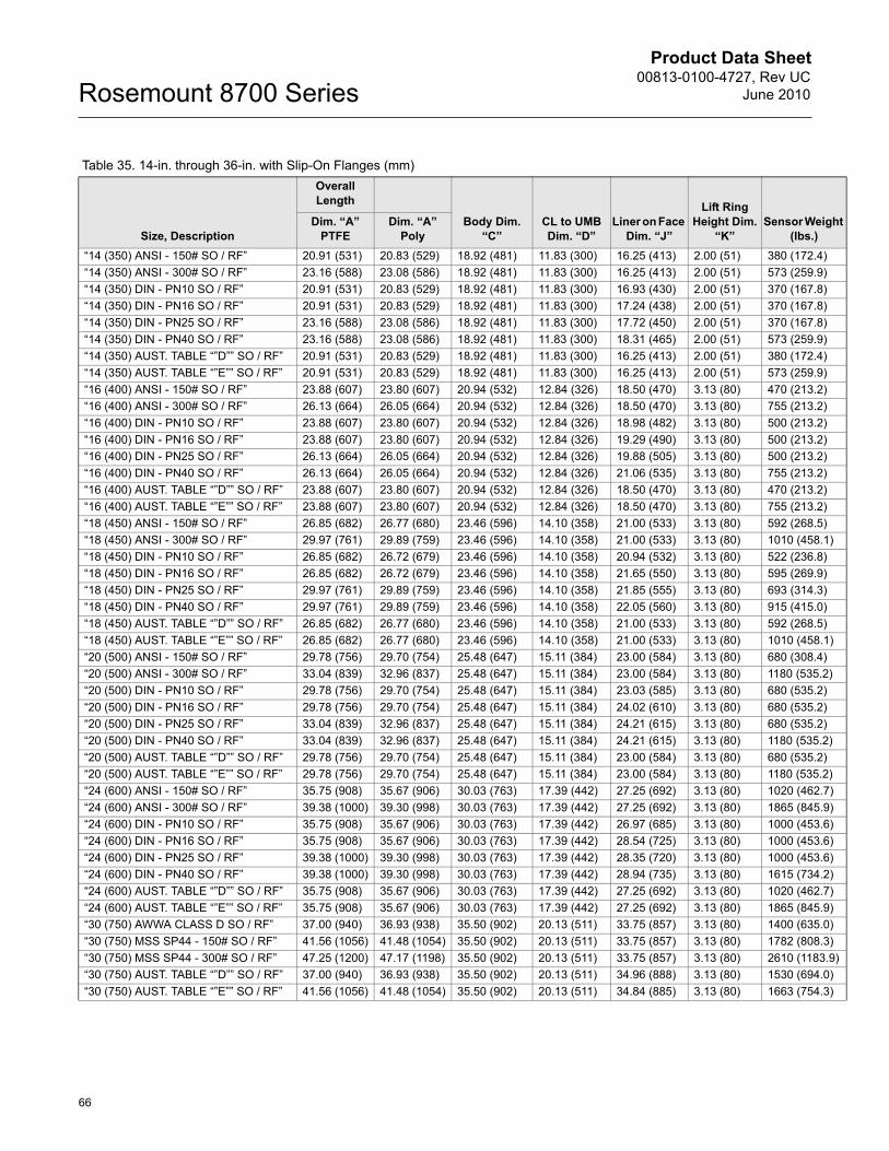
Product Data Sheet00813-0100-4727, Rev UC
June 2010Rosemount 8700 Series
66
Table 35. 14-in. through 36-in. with Slip-On Flanges (mm)
Size, Description
Overall Length
Body Dim. “C”
CL to UMB Dim. “D”
Liner on Face Dim. “J”
Lift Ring Height Dim.
“K”Sensor Weight
(lbs.)Dim. “A”
PTFEDim. “A”
Poly“14 (350) ANSI - 150# SO / RF” 20.91 (531) 20.83 (529) 18.92 (481) 11.83 (300) 16.25 (413) 2.00 (51) 380 (172.4)“14 (350) ANSI - 300# SO / RF” 23.16 (588) 23.08 (586) 18.92 (481) 11.83 (300) 16.25 (413) 2.00 (51) 573 (259.9)“14 (350) DIN - PN10 SO / RF” 20.91 (531) 20.83 (529) 18.92 (481) 11.83 (300) 16.93 (430) 2.00 (51) 370 (167.8)“14 (350) DIN - PN16 SO / RF” 20.91 (531) 20.83 (529) 18.92 (481) 11.83 (300) 17.24 (438) 2.00 (51) 370 (167.8)“14 (350) DIN - PN25 SO / RF” 23.16 (588) 23.08 (586) 18.92 (481) 11.83 (300) 17.72 (450) 2.00 (51) 370 (167.8)“14 (350) DIN - PN40 SO / RF” 23.16 (588) 23.08 (586) 18.92 (481) 11.83 (300) 18.31 (465) 2.00 (51) 573 (259.9)“14 (350) AUST. TABLE “”D”” SO / RF” 20.91 (531) 20.83 (529) 18.92 (481) 11.83 (300) 16.25 (413) 2.00 (51) 380 (172.4)“14 (350) AUST. TABLE “”E”” SO / RF” 20.91 (531) 20.83 (529) 18.92 (481) 11.83 (300) 16.25 (413) 2.00 (51) 573 (259.9)“16 (400) ANSI - 150# SO / RF” 23.88 (607) 23.80 (607) 20.94 (532) 12.84 (326) 18.50 (470) 3.13 (80) 470 (213.2)“16 (400) ANSI - 300# SO / RF” 26.13 (664) 26.05 (664) 20.94 (532) 12.84 (326) 18.50 (470) 3.13 (80) 755 (213.2)“16 (400) DIN - PN10 SO / RF” 23.88 (607) 23.80 (607) 20.94 (532) 12.84 (326) 18.98 (482) 3.13 (80) 500 (213.2)“16 (400) DIN - PN16 SO / RF” 23.88 (607) 23.80 (607) 20.94 (532) 12.84 (326) 19.29 (490) 3.13 (80) 500 (213.2)“16 (400) DIN - PN25 SO / RF” 26.13 (664) 26.05 (664) 20.94 (532) 12.84 (326) 19.88 (505) 3.13 (80) 500 (213.2)“16 (400) DIN - PN40 SO / RF” 26.13 (664) 26.05 (664) 20.94 (532) 12.84 (326) 21.06 (535) 3.13 (80) 755 (213.2)“16 (400) AUST. TABLE “”D”” SO / RF” 23.88 (607) 23.80 (607) 20.94 (532) 12.84 (326) 18.50 (470) 3.13 (80) 470 (213.2)“16 (400) AUST. TABLE “”E”” SO / RF” 23.88 (607) 23.80 (607) 20.94 (532) 12.84 (326) 18.50 (470) 3.13 (80) 755 (213.2)“18 (450) ANSI - 150# SO / RF” 26.85 (682) 26.77 (680) 23.46 (596) 14.10 (358) 21.00 (533) 3.13 (80) 592 (268.5)“18 (450) ANSI - 300# SO / RF” 29.97 (761) 29.89 (759) 23.46 (596) 14.10 (358) 21.00 (533) 3.13 (80) 1010 (458.1)“18 (450) DIN - PN10 SO / RF” 26.85 (682) 26.72 (679) 23.46 (596) 14.10 (358) 20.94 (532) 3.13 (80) 522 (236.8)“18 (450) DIN - PN16 SO / RF” 26.85 (682) 26.72 (679) 23.46 (596) 14.10 (358) 21.65 (550) 3.13 (80) 595 (269.9)“18 (450) DIN - PN25 SO / RF” 29.97 (761) 29.89 (759) 23.46 (596) 14.10 (358) 21.85 (555) 3.13 (80) 693 (314.3)“18 (450) DIN - PN40 SO / RF” 29.97 (761) 29.89 (759) 23.46 (596) 14.10 (358) 22.05 (560) 3.13 (80) 915 (415.0)“18 (450) AUST. TABLE “”D”” SO / RF” 26.85 (682) 26.77 (680) 23.46 (596) 14.10 (358) 21.00 (533) 3.13 (80) 592 (268.5)“18 (450) AUST. TABLE “”E”” SO / RF” 26.85 (682) 26.77 (680) 23.46 (596) 14.10 (358) 21.00 (533) 3.13 (80) 1010 (458.1)“20 (500) ANSI - 150# SO / RF” 29.78 (756) 29.70 (754) 25.48 (647) 15.11 (384) 23.00 (584) 3.13 (80) 680 (308.4)“20 (500) ANSI - 300# SO / RF” 33.04 (839) 32.96 (837) 25.48 (647) 15.11 (384) 23.00 (584) 3.13 (80) 1180 (535.2)“20 (500) DIN - PN10 SO / RF” 29.78 (756) 29.70 (754) 25.48 (647) 15.11 (384) 23.03 (585) 3.13 (80) 680 (535.2)“20 (500) DIN - PN16 SO / RF” 29.78 (756) 29.70 (754) 25.48 (647) 15.11 (384) 24.02 (610) 3.13 (80) 680 (535.2)“20 (500) DIN - PN25 SO / RF” 33.04 (839) 32.96 (837) 25.48 (647) 15.11 (384) 24.21 (615) 3.13 (80) 680 (535.2)“20 (500) DIN - PN40 SO / RF” 33.04 (839) 32.96 (837) 25.48 (647) 15.11 (384) 24.21 (615) 3.13 (80) 1180 (535.2)“20 (500) AUST. TABLE “”D”” SO / RF” 29.78 (756) 29.70 (754) 25.48 (647) 15.11 (384) 23.00 (584) 3.13 (80) 680 (535.2)“20 (500) AUST. TABLE “”E”” SO / RF” 29.78 (756) 29.70 (754) 25.48 (647) 15.11 (384) 23.00 (584) 3.13 (80) 1180 (535.2)“24 (600) ANSI - 150# SO / RF” 35.75 (908) 35.67 (906) 30.03 (763) 17.39 (442) 27.25 (692) 3.13 (80) 1020 (462.7)“24 (600) ANSI - 300# SO / RF” 39.38 (1000) 39.30 (998) 30.03 (763) 17.39 (442) 27.25 (692) 3.13 (80) 1865 (845.9)“24 (600) DIN - PN10 SO / RF” 35.75 (908) 35.67 (906) 30.03 (763) 17.39 (442) 26.97 (685) 3.13 (80) 1000 (453.6)“24 (600) DIN - PN16 SO / RF” 35.75 (908) 35.67 (906) 30.03 (763) 17.39 (442) 28.54 (725) 3.13 (80) 1000 (453.6)“24 (600) DIN - PN25 SO / RF” 39.38 (1000) 39.30 (998) 30.03 (763) 17.39 (442) 28.35 (720) 3.13 (80) 1000 (453.6)“24 (600) DIN - PN40 SO / RF” 39.38 (1000) 39.30 (998) 30.03 (763) 17.39 (442) 28.94 (735) 3.13 (80) 1615 (734.2)“24 (600) AUST. TABLE “”D”” SO / RF” 35.75 (908) 35.67 (906) 30.03 (763) 17.39 (442) 27.25 (692) 3.13 (80) 1020 (462.7)“24 (600) AUST. TABLE “”E”” SO / RF” 35.75 (908) 35.67 (906) 30.03 (763) 17.39 (442) 27.25 (692) 3.13 (80) 1865 (845.9)“30 (750) AWWA CLASS D SO / RF” 37.00 (940) 36.93 (938) 35.50 (902) 20.13 (511) 33.75 (857) 3.13 (80) 1400 (635.0)“30 (750) MSS SP44 - 150# SO / RF” 41.56 (1056) 41.48 (1054) 35.50 (902) 20.13 (511) 33.75 (857) 3.13 (80) 1782 (808.3)“30 (750) MSS SP44 - 300# SO / RF” 47.25 (1200) 47.17 (1198) 35.50 (902) 20.13 (511) 33.75 (857) 3.13 (80) 2610 (1183.9)“30 (750) AUST. TABLE “”D”” SO / RF” 37.00 (940) 36.93 (938) 35.50 (902) 20.13 (511) 34.96 (888) 3.13 (80) 1530 (694.0)“30 (750) AUST. TABLE “”E”” SO / RF” 41.56 (1056) 41.48 (1054) 35.50 (902) 20.13 (511) 34.84 (885) 3.13 (80) 1663 (754.3)
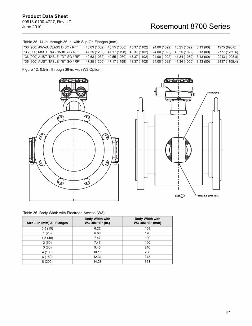
Product Data Sheet00813-0100-4727, Rev UCJune 2010
67
Rosemount 8700 Series
Figure 12. 0.5-in. through 36-in. with W3 Option
“36 (900) AWWA CLASS D SO / RF” 40.63 (1032) 40.55 (1030) 43.37 (1102) 24.00 (1022) 40.25 (1022) 3.13 (80) 1975 (895.8)“36 (900) MSS SP44 - 150# SO / RF” 47.25 (1200) 47.17 (1198) 43.37 (1102) 24.00 (1022) 40.25 (1022) 3.13 (80) 2777 (1259.6)“36 (900) AUST. TABLE “”D”” SO / RF” 40.63 (1032) 40.55 (1030) 43.37 (1102) 24.00 (1022) 41.34 (1050) 3.13 (80) 2213 (1003.8)“36 (900) AUST. TABLE “”E”” SO / RF” 47.25 (1200) 47.17 (1198) 43.37 (1102) 24.00 (1022) 41.34 (1050) 3.13 (80) 2437 (1105.4)
Table 35. 14-in. through 36-in. with Slip-On Flanges (mm)
Table 36. Body Width with Electrode Access (W3)
Size -- in (mm) All FlangesBody Width with W3 DIM “E” (in.)
Body Width with W3 DIM “E” (mm)
0.5 (15) 6.22 1581 (25) 6.68 170
1.5 (40) 7.47 1902 (50) 7.47 1903 (80) 9.45 240
4 (100) 10.15 2586 (150) 12.34 3138 (200) 14.28 363
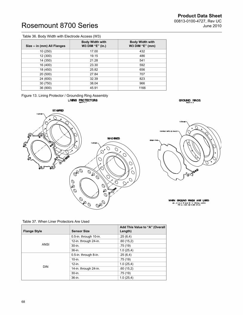
Product Data Sheet00813-0100-4727, Rev UC
June 2010Rosemount 8700 Series
68
Figure 13. Lining Protector / Grounding Ring Assembly
10 (250) 17.00 43212 (300) 19.15 48614 (350) 21.28 54116 (400) 23.30 59218 (450) 25.82 65620 (500) 27.84 70724 (600) 32.39 82330 (750) 38.04 96636 (900) 45.91 1166
Table 36. Body Width with Electrode Access (W3)
Size -- in (mm) All FlangesBody Width with W3 DIM “E” (in.)
Body Width with W3 DIM “E” (mm)
Table 37. When Liner Protectors Are Used
Flange Style Sensor SizeAdd This Value to “A” (Overall Length)
ANSI
0.5-in. through 10-in. .25 (6,4)12-in. through 24-in. .60 (15,2)30-in. .75 (19)36-in. 1.0 (25,4)
DIN
0.5-in. through 8-in. .25 (6,4)10-in. .75 (19)12-in. 1.0 (25,4)14-in. through 24-in. .60 (15,2)30-in. .75 (19)36-in. 1.0 (25,4)
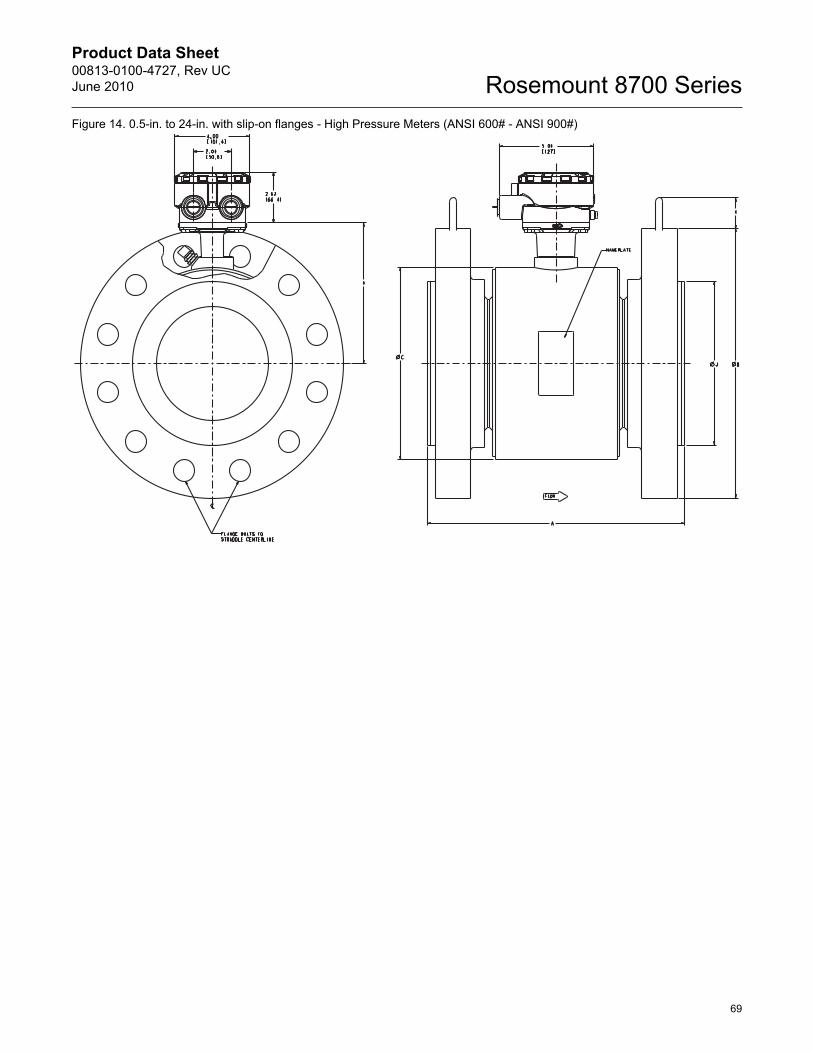
Product Data Sheet00813-0100-4727, Rev UCJune 2010
69
Rosemount 8700 SeriesFigure 14. 0.5-in. to 24-in. with slip-on flanges - High Pressure Meters (ANSI 600# - ANSI 900#)
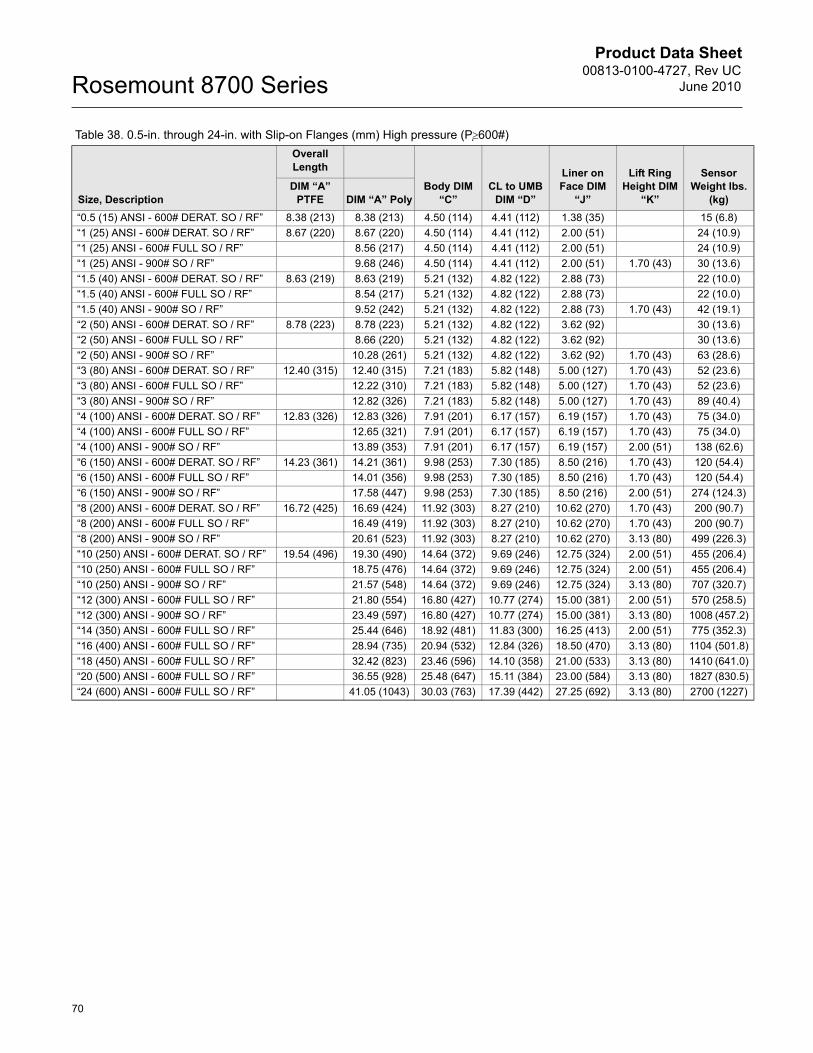
Product Data Sheet00813-0100-4727, Rev UC
June 2010Rosemount 8700 Series
70
Table 38. 0.5-in. through 24-in. with Slip-on Flanges (mm) High pressure (Pt600#)
Size, Description
Overall Length
Body DIM “C”
CL to UMB DIM “D”
Liner on Face DIM
“J”
Lift Ring Height DIM
“K”
Sensor Weight lbs.
(kg)DIM “A”
PTFE DIM “A” Poly“0.5 (15) ANSI - 600# DERAT. SO / RF” 8.38 (213) 8.38 (213) 4.50 (114) 4.41 (112) 1.38 (35) 15 (6.8)“1 (25) ANSI - 600# DERAT. SO / RF” 8.67 (220) 8.67 (220) 4.50 (114) 4.41 (112) 2.00 (51) 24 (10.9)“1 (25) ANSI - 600# FULL SO / RF” 8.56 (217) 4.50 (114) 4.41 (112) 2.00 (51) 24 (10.9)“1 (25) ANSI - 900# SO / RF” 9.68 (246) 4.50 (114) 4.41 (112) 2.00 (51) 1.70 (43) 30 (13.6)“1.5 (40) ANSI - 600# DERAT. SO / RF” 8.63 (219) 8.63 (219) 5.21 (132) 4.82 (122) 2.88 (73) 22 (10.0)“1.5 (40) ANSI - 600# FULL SO / RF” 8.54 (217) 5.21 (132) 4.82 (122) 2.88 (73) 22 (10.0)“1.5 (40) ANSI - 900# SO / RF” 9.52 (242) 5.21 (132) 4.82 (122) 2.88 (73) 1.70 (43) 42 (19.1)“2 (50) ANSI - 600# DERAT. SO / RF” 8.78 (223) 8.78 (223) 5.21 (132) 4.82 (122) 3.62 (92) 30 (13.6)“2 (50) ANSI - 600# FULL SO / RF” 8.66 (220) 5.21 (132) 4.82 (122) 3.62 (92) 30 (13.6)“2 (50) ANSI - 900# SO / RF” 10.28 (261) 5.21 (132) 4.82 (122) 3.62 (92) 1.70 (43) 63 (28.6)“3 (80) ANSI - 600# DERAT. SO / RF” 12.40 (315) 12.40 (315) 7.21 (183) 5.82 (148) 5.00 (127) 1.70 (43) 52 (23.6)“3 (80) ANSI - 600# FULL SO / RF” 12.22 (310) 7.21 (183) 5.82 (148) 5.00 (127) 1.70 (43) 52 (23.6)“3 (80) ANSI - 900# SO / RF” 12.82 (326) 7.21 (183) 5.82 (148) 5.00 (127) 1.70 (43) 89 (40.4)“4 (100) ANSI - 600# DERAT. SO / RF” 12.83 (326) 12.83 (326) 7.91 (201) 6.17 (157) 6.19 (157) 1.70 (43) 75 (34.0)“4 (100) ANSI - 600# FULL SO / RF” 12.65 (321) 7.91 (201) 6.17 (157) 6.19 (157) 1.70 (43) 75 (34.0)“4 (100) ANSI - 900# SO / RF” 13.89 (353) 7.91 (201) 6.17 (157) 6.19 (157) 2.00 (51) 138 (62.6)“6 (150) ANSI - 600# DERAT. SO / RF” 14.23 (361) 14.21 (361) 9.98 (253) 7.30 (185) 8.50 (216) 1.70 (43) 120 (54.4)“6 (150) ANSI - 600# FULL SO / RF” 14.01 (356) 9.98 (253) 7.30 (185) 8.50 (216) 1.70 (43) 120 (54.4)“6 (150) ANSI - 900# SO / RF” 17.58 (447) 9.98 (253) 7.30 (185) 8.50 (216) 2.00 (51) 274 (124.3)“8 (200) ANSI - 600# DERAT. SO / RF” 16.72 (425) 16.69 (424) 11.92 (303) 8.27 (210) 10.62 (270) 1.70 (43) 200 (90.7)“8 (200) ANSI - 600# FULL SO / RF” 16.49 (419) 11.92 (303) 8.27 (210) 10.62 (270) 1.70 (43) 200 (90.7)“8 (200) ANSI - 900# SO / RF” 20.61 (523) 11.92 (303) 8.27 (210) 10.62 (270) 3.13 (80) 499 (226.3)“10 (250) ANSI - 600# DERAT. SO / RF” 19.54 (496) 19.30 (490) 14.64 (372) 9.69 (246) 12.75 (324) 2.00 (51) 455 (206.4)“10 (250) ANSI - 600# FULL SO / RF” 18.75 (476) 14.64 (372) 9.69 (246) 12.75 (324) 2.00 (51) 455 (206.4)“10 (250) ANSI - 900# SO / RF” 21.57 (548) 14.64 (372) 9.69 (246) 12.75 (324) 3.13 (80) 707 (320.7)“12 (300) ANSI - 600# FULL SO / RF” 21.80 (554) 16.80 (427) 10.77 (274) 15.00 (381) 2.00 (51) 570 (258.5)“12 (300) ANSI - 900# SO / RF” 23.49 (597) 16.80 (427) 10.77 (274) 15.00 (381) 3.13 (80) 1008 (457.2)“14 (350) ANSI - 600# FULL SO / RF” 25.44 (646) 18.92 (481) 11.83 (300) 16.25 (413) 2.00 (51) 775 (352.3)“16 (400) ANSI - 600# FULL SO / RF” 28.94 (735) 20.94 (532) 12.84 (326) 18.50 (470) 3.13 (80) 1104 (501.8)“18 (450) ANSI - 600# FULL SO / RF” 32.42 (823) 23.46 (596) 14.10 (358) 21.00 (533) 3.13 (80) 1410 (641.0)“20 (500) ANSI - 600# FULL SO / RF” 36.55 (928) 25.48 (647) 15.11 (384) 23.00 (584) 3.13 (80) 1827 (830.5)“24 (600) ANSI - 600# FULL SO / RF” 41.05 (1043) 30.03 (763) 17.39 (442) 27.25 (692) 3.13 (80) 2700 (1227)
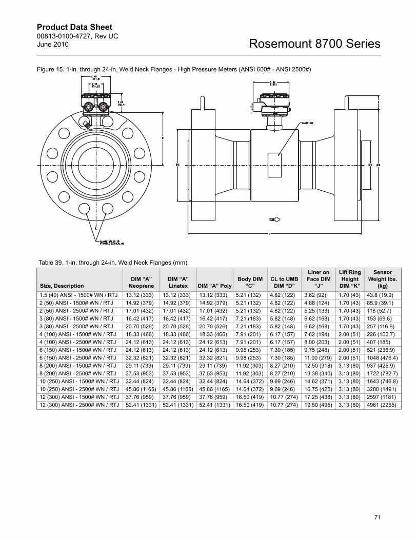
Product Data Sheet00813-0100-4727, Rev UCJune 2010
71
Rosemount 8700 Series
Figure 15. 1-in. through 24-in. Weld Neck Flanges - High Pressure Meters (ANSI 600# - ANSI 2500#)
Table 39. 1-in. through 24-in. Weld Neck Flanges (mm)
Size, DescriptionDIM “A”
NeopreneDIM “A” Linatex DIM “A” Poly
Body DIM “C”
CL to UMB DIM “D”
Liner on Face DIM
“J”
Lift Ring Height
DIM “K”
Sensor Weight lbs.
(kg)1.5 (40) ANSI - 1500# WN / RTJ 13.12 (333) 13.12 (333) 13.12 (333) 5.21 (132) 4.82 (122) 3.62 (92) 1.70 (43) 43.8 (19.9)2 (50) ANSI - 1500# WN / RTJ 14.92 (379) 14.92 (379) 14.92 (379) 5.21 (132) 4.82 (122) 4.88 (124) 1.70 (43) 85.9 (39.1)2 (50) ANSI - 2500# WN / RTJ 17.01 (432) 17.01 (432) 17.01 (432) 5.21 (132) 4.82 (122) 5.25 (133) 1.70 (43) 116 (52.7)3 (80) ANSI - 1500# WN / RTJ 16.42 (417) 16.42 (417) 16.42 (417) 7.21 (183) 5.82 (148) 6.62 (168) 1.70 (43) 153 (69.6)3 (80) ANSI - 2500# WN / RTJ 20.70 (526) 20.70 (526) 20.70 (526) 7.21 (183) 5.82 (148) 6.62 (168) 1.70 (43) 257 (116.6)4 (100) ANSI - 1500# WN / RTJ 18.33 (466) 18.33 (466) 18.33 (466) 7.91 (201) 6.17 (157) 7.62 (194) 2.00 (51) 226 (102.7)4 (100) ANSI - 2500# WN / RTJ 24.12 (613) 24.12 (613) 24.12 (613) 7.91 (201) 6.17 (157) 8.00 (203) 2.00 (51) 407 (185)6 (150) ANSI - 1500# WN / RTJ 24.12 (613) 24.12 (613) 24.12 (613) 9.98 (253) 7.30 (185) 9.75 (248) 2.00 (51) 521 (236.9)6 (150) ANSI - 2500# WN / RTJ 32.32 (821) 32.32 (821) 32.32 (821) 9.98 (253) 7.30 (185) 11.00 (279) 2.00 (51) 1048 (476.4)8 (200) ANSI - 1500# WN / RTJ 29.11 (739) 29.11 (739) 29.11 (739) 11.92 (303) 8.27 (210) 12.50 (318) 3.13 (80) 937 (425.9)8 (200) ANSI - 2500# WN / RTJ 37.53 (953) 37.53 (953) 37.53 (953) 11.92 (303) 8.27 (210) 13.38 (340) 3.13 (80) 1722 (782.7)10 (250) ANSI - 1500# WN / RTJ 32.44 (824) 32.44 (824) 32.44 (824) 14.64 (372) 9.69 (246) 14.62 (371) 3.13 (80) 1643 (746.8)10 (250) ANSI - 2500# WN / RTJ 45.86 (1165) 45.86 (1165) 45.86 (1165) 14.64 (372) 9.69 (246) 16.75 (425) 3.13 (80) 3280 (1491)12 (300) ANSI - 1500# WN / RTJ 37.76 (959) 37.76 (959) 37.76 (959) 16.50 (419) 10.77 (274) 17.25 (438) 3.13 (80) 2597 (1181)12 (300) ANSI - 2500# WN / RTJ 52.41 (1331) 52.41 (1331) 52.41 (1331) 16.50 (419) 10.77 (274) 19.50 (495) 3.13 (80) 4961 (2255)
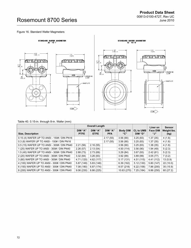
Product Data Sheet00813-0100-4727, Rev UC
June 2010Rosemount 8700 Series
72
Figure 16. Standard Wafer Magmeters
Table 40. 0.15-in. through 8-in. Wafer (mm)Overall Length
Body DIM “C”
CL to UMB DIM “D”
Liner on Face DIM
“J”
Sensor Weight lbs.
(kg)Size, DescriptionDIM “A”
PTFEDIM “A”
ETFEDIM “A”
PFA0.15 (4) WAFER UP TO ANSI - 150# / DIN PN16 2.17 (55) 3.56 (90) 3.25 (83) 1.37 (35) 4 (1.8)0.3 (8) WAFER UP TO ANSI - 150# / DIN PN16 2.17 (55) 3.56 (90) 3.25 (83) 1.37 (35) 4 (1.8)0.5 (15) WAFER UP TO ANSI - 300# / DIN PN40 2.21 (56) 2.16 (55) 3.56 (90) 3.25 (83) 1.38 (35) 4 (1.8)1 (25) WAFER UP TO ANSI - 300# / DIN PN40 2.26 (57) 2.13 (54) 4.50 (114) 3.56 (90) 1.94 (49) 5 (2.3)1.5 (40) WAFER UP TO ANSI - 300# / DIN PN40 2.88 (73) 2.73 (69) 3.29 (84) 3.67 (93) 2.42 (61) 5 (2.3)2 (20) WAFER UP TO ANSI - 300# / DIN PN40 3.32 (84) 3.26 (83) 3.92 (99) 3.89 (99) 3.05 (77) 7 (3.2)3 (80) WAFER UP TO ANSI - 300# / DIN PN40 4.71 (120) 4.62 (117) 5.17 (131) 4.51 (115) 4.41 (112) 13 (5.9)4 (100) WAFER UP TO ANSI - 300# / DIN PN40 5.87 (149) 5.83 (148) 6.39 (162) 5.12 (130) 5.80 (147) 22 (10.0)6 (150) WAFER UP TO ANSI - 300# / DIN PN40 7.08 (180) 6.87 (174) 8.57 (218) 6.22 (158) 7.86 (200) 35 (15.9)8 (200) WAFER UP TO ANSI - 300# / DIN PN40 9.06 (230) 8.86 (225) 10.63 (270) 7.25 (184) 9.86 (250) 60 (27.2)
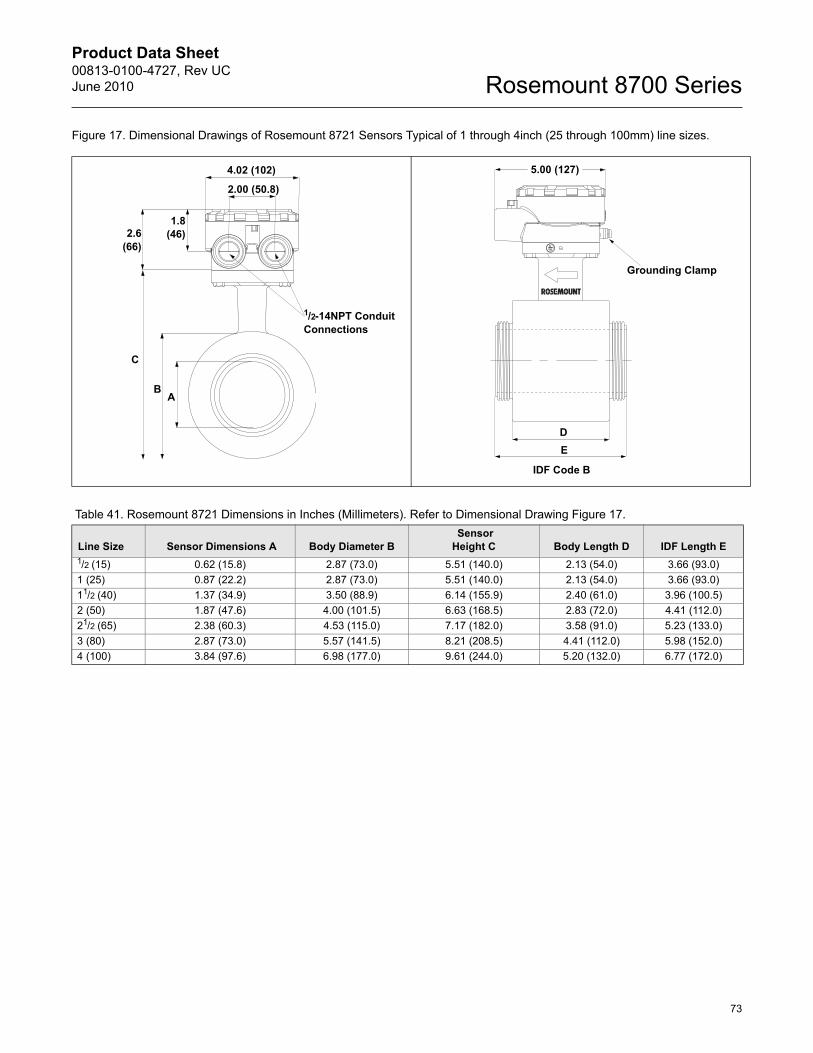
Product Data Sheet00813-0100-4727, Rev UCJune 2010
73
Rosemount 8700 Series
Figure 17. Dimensional Drawings of Rosemount 8721 Sensors Typical of 1 through 4inch (25 through 100mm) line sizes.
4.02 (102)
2.00 (50.8)
1.8(46)2.6
(66)
C
BA
1/2-14NPT Conduit Connections
5.00 (127)
Grounding Clamp
DE
IDF Code B
Table 41. Rosemount 8721 Dimensions in Inches (Millimeters). Refer to Dimensional Drawing Figure 17.
Line Size Sensor Dimensions A Body Diameter B Sensor Height C Body Length D IDF Length E
1/2 (15) 0.62 (15.8) 2.87 (73.0) 5.51 (140.0) 2.13 (54.0) 3.66 (93.0)1 (25) 0.87 (22.2) 2.87 (73.0) 5.51 (140.0) 2.13 (54.0) 3.66 (93.0)11/2 (40) 1.37 (34.9) 3.50 (88.9) 6.14 (155.9) 2.40 (61.0) 3.96 (100.5)2 (50) 1.87 (47.6) 4.00 (101.5) 6.63 (168.5) 2.83 (72.0) 4.41 (112.0)21/2 (65) 2.38 (60.3) 4.53 (115.0) 7.17 (182.0) 3.58 (91.0) 5.23 (133.0)3 (80) 2.87 (73.0) 5.57 (141.5) 8.21 (208.5) 4.41 (112.0) 5.98 (152.0)4 (100) 3.84 (97.6) 6.98 (177.0) 9.61 (244.0) 5.20 (132.0) 6.77 (172.0)
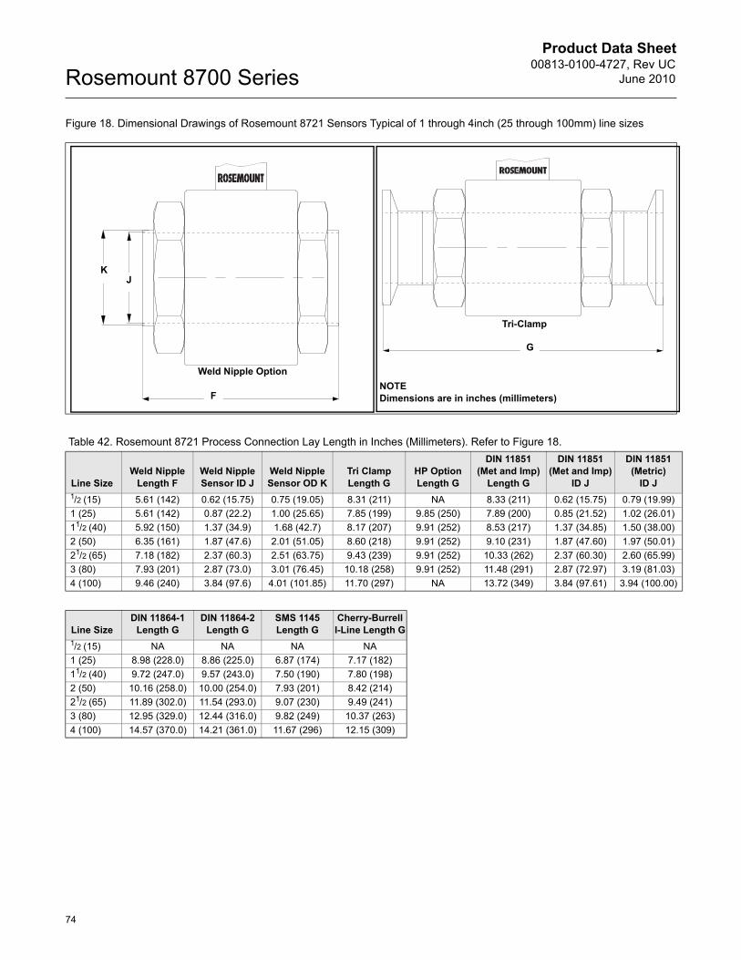
Product Data Sheet00813-0100-4727, Rev UC
June 2010Rosemount 8700 Series
74
Figure 18. Dimensional Drawings of Rosemount 8721 Sensors Typical of 1 through 4inch (25 through 100mm) line sizes
F
JK
Weld Nipple Option
G
NOTEDimensions are in inches (millimeters)
Tri-Clamp
Table 42. Rosemount 8721 Process Connection Lay Length in Inches (Millimeters). Refer to Figure 18.
Line SizeWeld Nipple
Length FWeld Nipple Sensor ID J
Weld Nipple Sensor OD K
Tri Clamp Length G
HP OptionLength G
DIN 11851 (Met and Imp)
Length G
DIN 11851 (Met and Imp)
ID J
DIN 11851 (Metric)
ID J1/2 (15) 5.61 (142) 0.62 (15.75) 0.75 (19.05) 8.31 (211) NA 8.33 (211) 0.62 (15.75) 0.79 (19.99)1 (25) 5.61 (142) 0.87 (22.2) 1.00 (25.65) 7.85 (199) 9.85 (250) 7.89 (200) 0.85 (21.52) 1.02 (26.01)11/2 (40) 5.92 (150) 1.37 (34.9) 1.68 (42.7) 8.17 (207) 9.91 (252) 8.53 (217) 1.37 (34.85) 1.50 (38.00)2 (50) 6.35 (161) 1.87 (47.6) 2.01 (51.05) 8.60 (218) 9.91 (252) 9.10 (231) 1.87 (47.60) 1.97 (50.01)21/2 (65) 7.18 (182) 2.37 (60.3) 2.51 (63.75) 9.43 (239) 9.91 (252) 10.33 (262) 2.37 (60.30) 2.60 (65.99)3 (80) 7.93 (201) 2.87 (73.0) 3.01 (76.45) 10.18 (258) 9.91 (252) 11.48 (291) 2.87 (72.97) 3.19 (81.03)4 (100) 9.46 (240) 3.84 (97.6) 4.01 (101.85) 11.70 (297) NA 13.72 (349) 3.84 (97.61) 3.94 (100.00)
Line SizeDIN 11864-1
Length GDIN 11864-2
Length GSMS 1145 Length G
Cherry-Burrell I-Line Length G
1/2 (15) NA NA NA NA1 (25) 8.98 (228.0) 8.86 (225.0) 6.87 (174) 7.17 (182)11/2 (40) 9.72 (247.0) 9.57 (243.0) 7.50 (190) 7.80 (198)2 (50) 10.16 (258.0) 10.00 (254.0) 7.93 (201) 8.42 (214)21/2 (65) 11.89 (302.0) 11.54 (293.0) 9.07 (230) 9.49 (241)3 (80) 12.95 (329.0) 12.44 (316.0) 9.82 (249) 10.37 (263)4 (100) 14.57 (370.0) 14.21 (361.0) 11.67 (296) 12.15 (309)
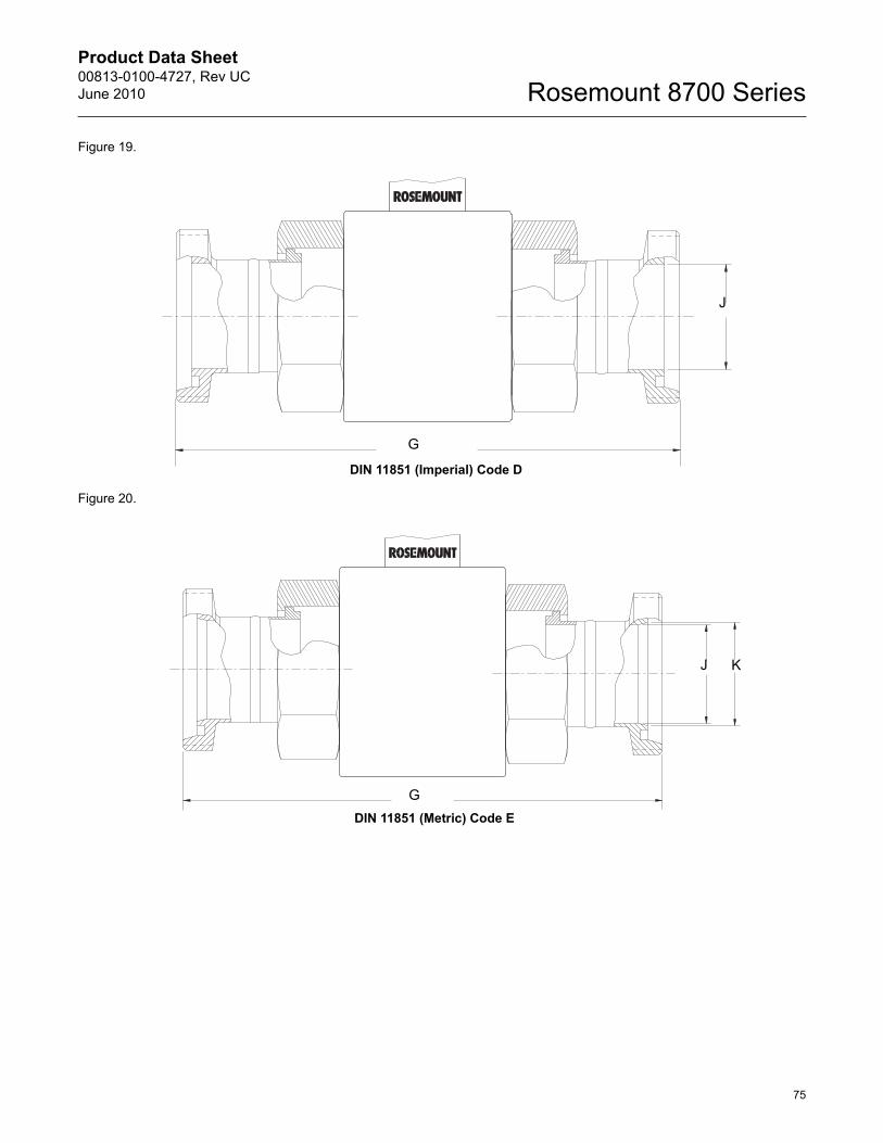
Product Data Sheet00813-0100-4727, Rev UCJune 2010
75
Rosemount 8700 Series
Figure 19.
Figure 20.
J
G
DIN 11851 (Imperial) Code D
J K
GDIN 11851 (Metric) Code E
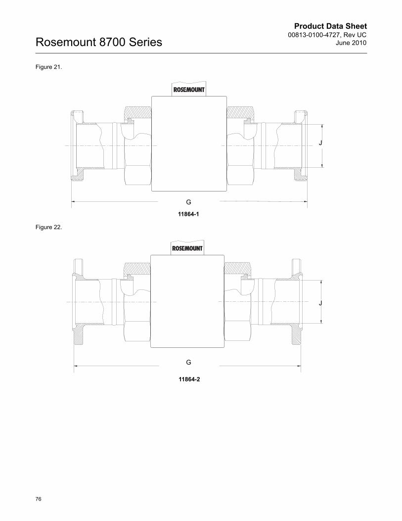
Product Data Sheet00813-0100-4727, Rev UC
June 2010Rosemount 8700 Series
76
Figure 21.
Figure 22.
J
G
11864-1
J
G
11864-2
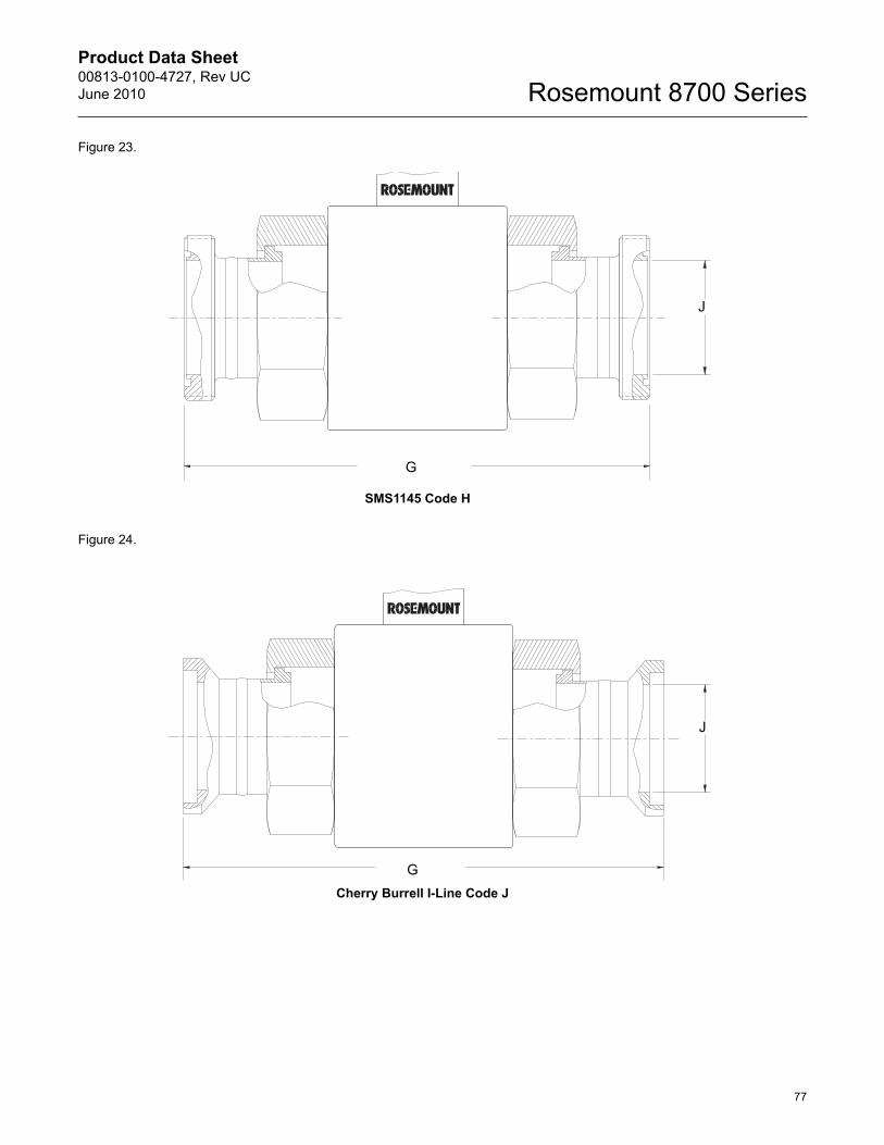
Product Data Sheet00813-0100-4727, Rev UCJune 2010
77
Rosemount 8700 Series
Figure 23.
Figure 24.
J
G
SMS1145 Code H
J
GCherry Burrell I-Line Code J
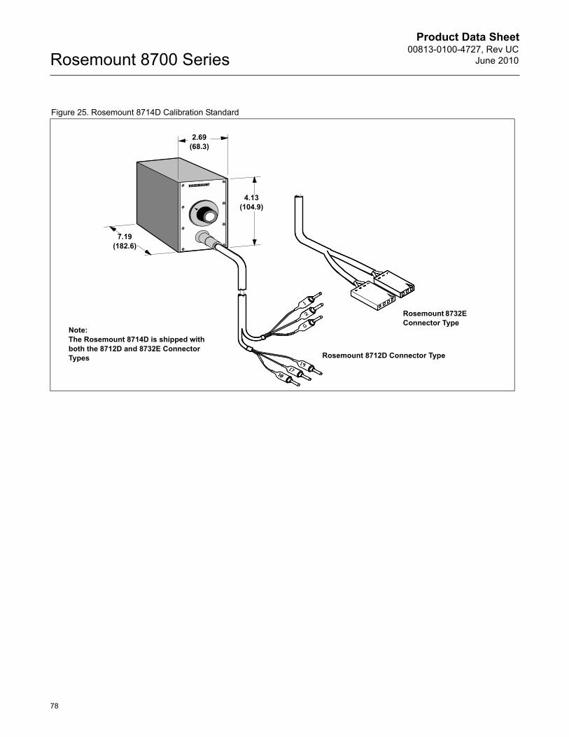
Product Data Sheet00813-0100-4727, Rev UC
June 2010Rosemount 8700 Series
78
Figure 25. Rosemount 8714D Calibration Standard
2.69(68.3)
4.13(104.9)
7.19(182.6)
Rosemount 8732E Connector Type
Rosemount 8712D Connector Type
Note: The Rosemount 8714D is shipped with both the 8712D and 8732E Connector Types

Product Data Sheet00813-0100-4727, Rev UCJune 2010
79
Rosemount 8700 Series
Emerson Process Management
00813-0100-4727 Rev UC, 6/10
Rosemount and the Rosemount logotype are registered trademarks of Rosemount Inc.The Emerson logo is a trade mark and service mark of Emerson Electric Co. PlantWeb is a mark of one of the Emerson Process Management companies.All other marks are the property of their respective owners.PlantWeb and DeltaV are trademarks of the Fisher-Rosemount Group of Companies.HART is a registered trademark of the HART Communication Foundations.Foundation is a trademark of the Fieldbus Foundation.Teflon and Tefzel are registered trademarks of E.I. du Pont de Nemours &Co.Tri-Clamp is a registered trademark of Tri-Clover, Inc. of the Alfa-Laval Group.Foxboro and I/A Series are registered trademarks of the Foxboro Company.ABB Fischer & Porter is a registered trademark of ABB Company.Eurofast and Minifast are registered trademarks of Turck Inc.Tri-Clamp is a registered trademark of Ladish Company.
Standard Terms and Conditions of Sale can be found at www.rosemount.com/terms_of_sale
Rosemount Inc.8200 Market BoulevardChanhassen, MN 55317 USAT (U.S.) 1-800-999-9307T (International) (952) 906-8888F (952) 949-7001
www.rosemount.com
Emerson Process Management FlowNeonstraat 1 6718 WX EdeThe Netherlands T +31 (0)318 495555F +31(0) 318 495556
Emerson Process ManagementSingapore Pte Ltd.1 Pandan CrescentSingapore 128461Tel (65) 777-8211Fax (65) [email protected]
Product Data Sheet00813-0100-4727, Rev UC
June 2010Rosemount 8700 Series
Emerson FZEP.O. Box 17033Jebel Ali Free ZoneDubai UAETel +971 4 811 8100Fax +971 4 886 5465