Embed Size (px)
Citation preview
Product Data Sheet00813-0100-4021, Rev SB
April 2019
Rosemount™ 3144P Temperature Transmitterwith Rosemount X-well™ Technology
For every responsibility you have, you are confronted with a number of challenges. You have aggressiveproduction and quality targets, but inaccurate or unavailable temperature measurements createunscheduled downtime and off-spec products. Loops may be running in manual because you don’t trustyour temperature measurement, requiring the attention of your maintenance staff and costing money inlost production. Additionally, improving safety and complying with government and company regulationsis made more difficult when you don’t have the information or tools needed to prove your compliance.
That is why companies are coming to Emerson™ – because they know they need reliable measurementsand visibility into their temperature measurements in order to address these challenges and achieve theirbusiness objectives. With the Rosemount 3144P Transmitter, you gain greater visibility into yourtemperature processes so you can improve safety, comply with regulations, make the most of your limitedresources, and reach your production and quality targets. By leveraging Rosemount X-well Technology,advanced diagnostic capabilities and the unparalleled reliability and accuracy of the transmitter, you canminimize off-spec product, reduce maintenance and downtime, improve the usage of your limitedresources, and meet regulatory demands.
Features and benefits
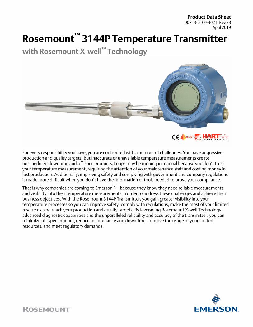
Rosemount X-well™ Technology provides a Complete Point Solution™ foraccurately measuring process temperature in monitoring applications withoutthe requirement of a thermowell or process penetration.
■ Simplify temperature measurement point specification, installation andmaintenance, and eliminate possible leak points.
■ Calculates a repeatable and accurate process temperature measurement via an in-transmitter thermal conductivity algorithm.
■ Measures pipe surface and ambient temperature, and utilizes the thermalconductivity properties of the installation and process piping in order to providean accurate process measurement.
ContentsFeatures and benefits........................................................................................................................................................................ 2
Ordering information........................................................................................................................................................................ 5
How to order Rosemount X-well™
Technology...................................................................................................................................9
Specifications.................................................................................................................................................................................. 10
Product Certifications......................................................................................................................................................................23
Dimensional drawings..................................................................................................................................................................... 34
April 2019
2 Emerson.com/Rosemount

Industry-leading temperature transmitter delivers unmatched field reliabilityand innovative process measurement solutions■ Superior accuracy and stability
■ Dual and single sensor capability with universal sensor inputs (RTD, T/C,mV, ohms)
■ Comprehensive sensor and process diagnostics offering
■ SIL3 Capable: IEC 61508 certified by an accredited 3rd party agency for usein safety instrumented systems up to SIL 3 (minimum requirement of singleuse [1oo1] for SIL 2 and redundant use [1oo2] for SIL 3)
■ Dual-compartment housing
■ Large LCD display
■ 4–20 mA /HART® with selectable revisions (5 and 7)
■ FOUNDATION™ Fieldbus, compliant to ITK 6.0 and NE107 standards
Improve efficiency with best-in-class product specifications and capabilities■ Reduce maintenance and improve performance with industry leading accuracy and stability.
■ Improve measurement accuracy by 75 percent with transmitter-sensor matching.
■ Ensure process health with system alerts and easy to use device dashboards.
■ Easily check device status and values on local LCD display with large percent range graph.
■ Achieve high reliability and installation ease with the industry's most rugged dual compartment design.
Optimize measurement reliability with diagnostics designed for any protocolon any host system
■ Thermocouple degradation diagnostic monitors the health of athermocouple loop, enabling preventative maintenance.
■ Minimum and maximum temperature tracking tracks andrecords temperature extremes of the process sensors and theambient environment.
■ Sensor drift alert detects sensor drift and alerts the user.
■ The Hot Backup™ feature provides temperature measurementredundancy.
April 2019
Emerson.com/Rosemount 3

Explore the benefits of a Complete Point Solution from Emerson■ An “Assemble To Sensor” option enables Emerson to
provide a complete point temperature solution, deliveringan installation-ready transmitter and sensor assembly.
■ Emerson offers a selection of RTDs, thermocouples, andthermowells that bring superior durability and Rosemountreliability to temperature sensing, complementing theRosemount Transmitter portfolio.
Experience global consistency and local support from numerous worldwideEmerson manufacturing sites
■ World-class manufacturing provides globally consistentproduct from every factory and the capacity to fulfill theneeds of any project, large or small.
■ Experienced instrumentation consultants help select theright product for any temperature application and advise onbest installation practices.
■ An extensive global network of Emerson service and supportpersonnel can be on-site when and where they are needed.
■ Make wireless installation and configuration easy with theEmerson Wireless Gateway.
Looking for a wireless temperature solution? For wireless applications that require superior performance and unmatched reliability,consider the Rosemount 648 Wireless Temperature Transmitter.
April 2019
4 Emerson.com/Rosemount
Ordering information
Rosemount™ 3144P Temperature Transmitter
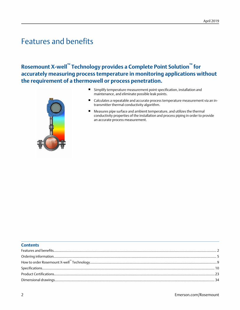
The industry-leading Rosemount 3144P Single Point TemperatureTransmitter delivers unmatched field reliability and innovative processmeasurement solutions and diagnostics
Transmitter features include:
■ Temperature measurement assembly with Rosemount X-wellTechnology (option code PT)
■ Dual and single sensor input capabilities
■ Transmitter-sensor matching (option code C2)
■ Integral transient protector (option code T1)
■ IEC 61508 Safety Certificate of Compliance (option code QT)
■ Advanced sensor and process diagnostics (option codes D01 andDA1)
■ Large, easy to read LCD display (option code M5)
■ “Assemble to Sensor” option (option code XA)
Specification and selection of product materials, options, or components must be made by the purchaser of the equipment. See formore information on material selection. When ordering Rosemount X-well™ Technology, specific option codes are required. See formore information.
Table 1: Rosemount 3144P Temperature Transmitter Ordering Information
The starred offerings (H) represent the most common options and should be selected for best delivery. The non-starred offeringsare subject to additional delivery lead time.
Model Product description
3144P Temperature transmitter
Housing style Material Conduit entry size
D1 Field mount housing, dual-compartment housing Aluminum ½–14-in. NPT ★
D2 Field mount housing, dual-compartment housing Aluminum M20 x 1,5 (CM20) ★
D3 Field mount housing, dual-compartment housing Aluminum PG 13.5 (PG11) ★
D4 Field mount housing, dual-compartment housing Aluminum JIS G ½ ★
D5 Field mount housing, dual-compartment housing Stainless steel ½–14-in. NPT ★
D6 Field mount housing, dual-compartment housing Stainless steel M20 x 1,5 (CM20) ★
D7 Field mount housing, dual-compartment housing Stainless steel PG 13.5 (PG11) ★
D8 Field mount housing, dual-compartment housing Stainless steel JIS G ½ ★
Transmitter output
A 4—20 mA with digital signal based on HART Protocol ★
F FOUNDATION Fieldbus digital signal (includes three AI function block and backup link active scheduler) ★
Measurement Configuration
1 Single-sensor input ★
April 2019
Emerson.com/Rosemount 5
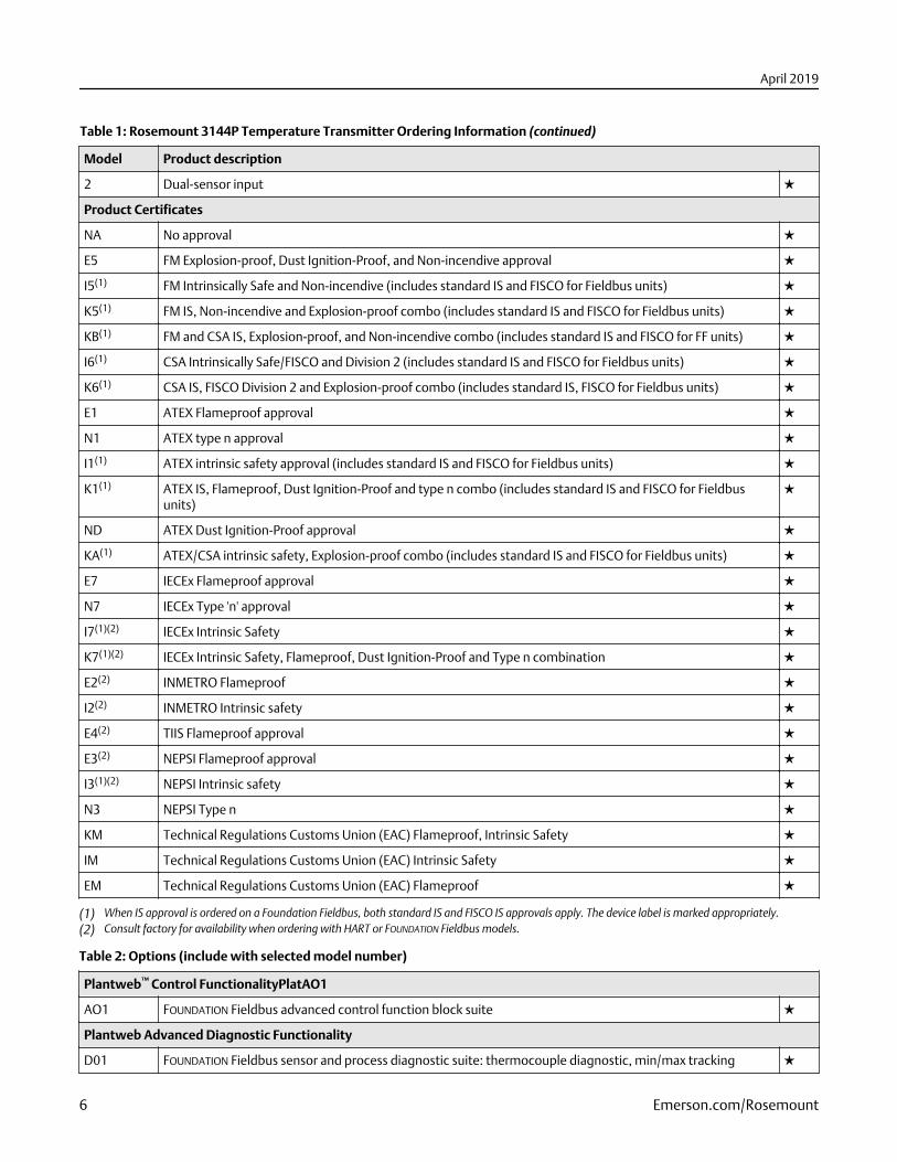
Table 1: Rosemount 3144P Temperature Transmitter Ordering Information (continued)
Model Product description
2 Dual-sensor input ★
Product Certificates
NA No approval ★
E5 FM Explosion-proof, Dust Ignition-Proof, and Non-incendive approval ★
I5(1) FM Intrinsically Safe and Non-incendive (includes standard IS and FISCO for Fieldbus units) ★
K5(1) FM IS, Non-incendive and Explosion-proof combo (includes standard IS and FISCO for Fieldbus units) ★
KB(1) FM and CSA IS, Explosion-proof, and Non-incendive combo (includes standard IS and FISCO for FF units) ★
I6(1) CSA Intrinsically Safe/FISCO and Division 2 (includes standard IS and FISCO for Fieldbus units) ★
K6(1) CSA IS, FISCO Division 2 and Explosion-proof combo (includes standard IS, FISCO for Fieldbus units) ★
E1 ATEX Flameproof approval ★
N1 ATEX type n approval ★
I1(1) ATEX intrinsic safety approval (includes standard IS and FISCO for Fieldbus units) ★
K1(1) ATEX IS, Flameproof, Dust Ignition-Proof and type n combo (includes standard IS and FISCO for Fieldbusunits)
★
ND ATEX Dust Ignition-Proof approval ★
KA(1) ATEX/CSA intrinsic safety, Explosion-proof combo (includes standard IS and FISCO for Fieldbus units) ★
E7 IECEx Flameproof approval ★
N7 IECEx Type 'n' approval ★
I7(1)(2) IECEx Intrinsic Safety ★
K7(1)(2) IECEx Intrinsic Safety, Flameproof, Dust Ignition-Proof and Type n combination ★
E2(2) INMETRO Flameproof ★
I2(2) INMETRO Intrinsic safety ★
E4(2) TIIS Flameproof approval ★
E3(2) NEPSI Flameproof approval ★
I3(1)(2) NEPSI Intrinsic safety ★
N3 NEPSI Type n ★
KM Technical Regulations Customs Union (EAC) Flameproof, Intrinsic Safety ★
IM Technical Regulations Customs Union (EAC) Intrinsic Safety ★
EM Technical Regulations Customs Union (EAC) Flameproof ★
(1) When IS approval is ordered on a Foundation Fieldbus, both standard IS and FISCO IS approvals apply. The device label is marked appropriately.(2) Consult factory for availability when ordering with HART or FOUNDATION Fieldbus models.
Table 2: Options (include with selected model number)
Plantweb™ Control FunctionalityPlatAO1
AO1 FOUNDATION Fieldbus advanced control function block suite ★
Plantweb Advanced Diagnostic Functionality
D01 FOUNDATION Fieldbus sensor and process diagnostic suite: thermocouple diagnostic, min/max tracking ★
April 2019
6 Emerson.com/Rosemount
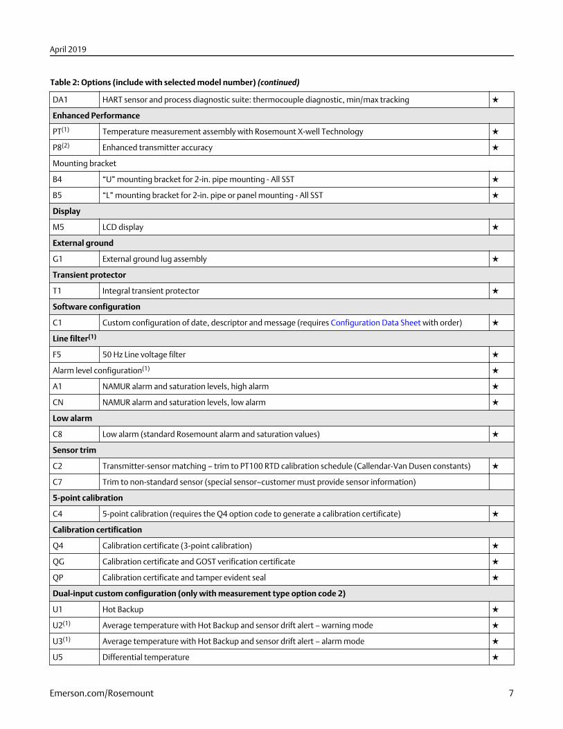
Table 2: Options (include with selected model number) (continued)
DA1 HART sensor and process diagnostic suite: thermocouple diagnostic, min/max tracking ★
Enhanced Performance
PT(1) Temperature measurement assembly with Rosemount X-well Technology ★
P8(2) Enhanced transmitter accuracy ★
Mounting bracket
B4 “U” mounting bracket for 2-in. pipe mounting - All SST ★
B5 “L” mounting bracket for 2-in. pipe or panel mounting - All SST ★
Display
M5 LCD display ★
External ground
G1 External ground lug assembly ★
Transient protector
T1 Integral transient protector ★
Software configuration
C1 Custom configuration of date, descriptor and message (requires Configuration Data Sheet with order) ★
Line filter(1)
F5 50 Hz Line voltage filter ★
Alarm level configuration(1) ★
A1 NAMUR alarm and saturation levels, high alarm ★
CN NAMUR alarm and saturation levels, low alarm ★
Low alarm
C8 Low alarm (standard Rosemount alarm and saturation values) ★
Sensor trim
C2 Transmitter-sensor matching – trim to PT100 RTD calibration schedule (Callendar-Van Dusen constants) ★
C7 Trim to non-standard sensor (special sensor–customer must provide sensor information)
5-point calibration
C4 5-point calibration (requires the Q4 option code to generate a calibration certificate) ★
Calibration certification
Q4 Calibration certificate (3-point calibration) ★
QG Calibration certificate and GOST verification certificate ★
QP Calibration certificate and tamper evident seal ★
Dual-input custom configuration (only with measurement type option code 2)
U1 Hot Backup ★
U2(1) Average temperature with Hot Backup and sensor drift alert – warning mode ★
U3(1) Average temperature with Hot Backup and sensor drift alert – alarm mode ★
U5 Differential temperature ★
April 2019
Emerson.com/Rosemount 7
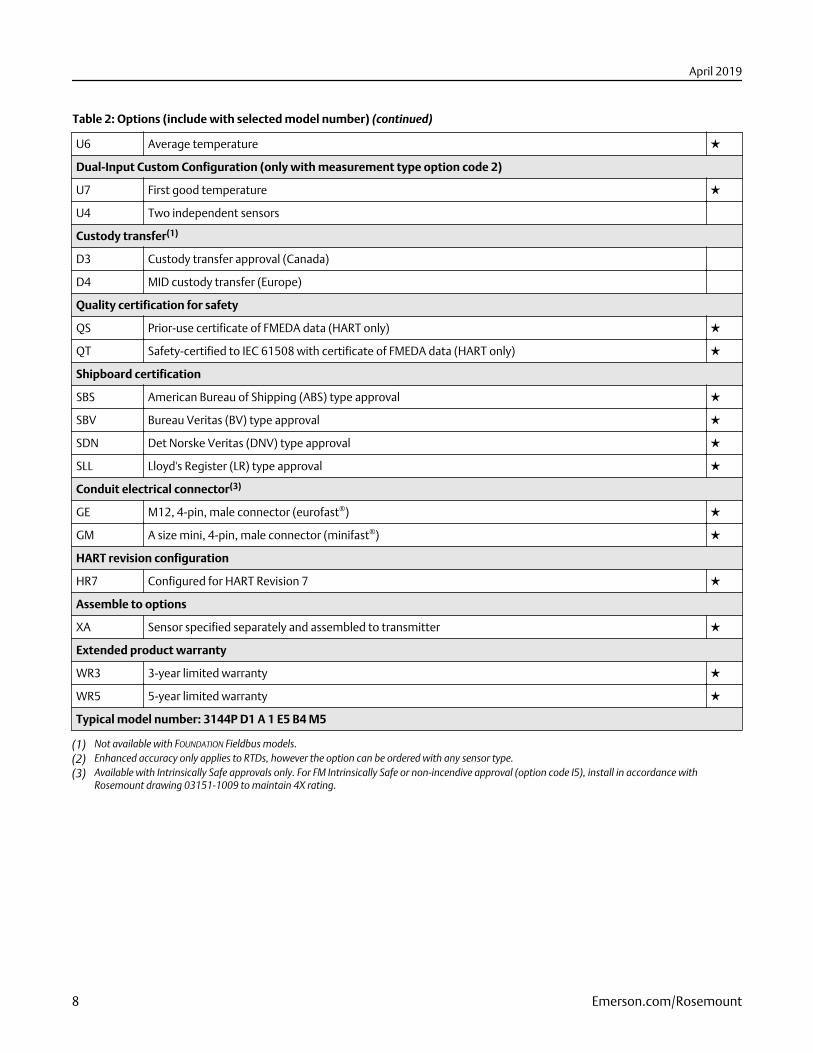
Table 2: Options (include with selected model number) (continued)
U6 Average temperature ★
Dual-Input Custom Configuration (only with measurement type option code 2)
U7 First good temperature ★
U4 Two independent sensors
Custody transfer(1)
D3 Custody transfer approval (Canada)
D4 MID custody transfer (Europe)
Quality certification for safety
QS Prior-use certificate of FMEDA data (HART only) ★
QT Safety-certified to IEC 61508 with certificate of FMEDA data (HART only) ★
Shipboard certification
SBS American Bureau of Shipping (ABS) type approval ★
SBV Bureau Veritas (BV) type approval ★
SDN Det Norske Veritas (DNV) type approval ★
SLL Lloyd's Register (LR) type approval ★
Conduit electrical connector(3)
GE M12, 4-pin, male connector (eurofast®) ★
GM A size mini, 4-pin, male connector (minifast®) ★
HART revision configuration
HR7 Configured for HART Revision 7 ★
Assemble to options
XA Sensor specified separately and assembled to transmitter ★
Extended product warranty
WR3 3-year limited warranty ★
WR5 5-year limited warranty ★
Typical model number: 3144P D1 A 1 E5 B4 M5
(1) Not available with FOUNDATION Fieldbus models.(2) Enhanced accuracy only applies to RTDs, however the option can be ordered with any sensor type.(3) Available with Intrinsically Safe approvals only. For FM Intrinsically Safe or non-incendive approval (option code I5), install in accordance with
Rosemount drawing 03151-1009 to maintain 4X rating.
April 2019
8 Emerson.com/Rosemount
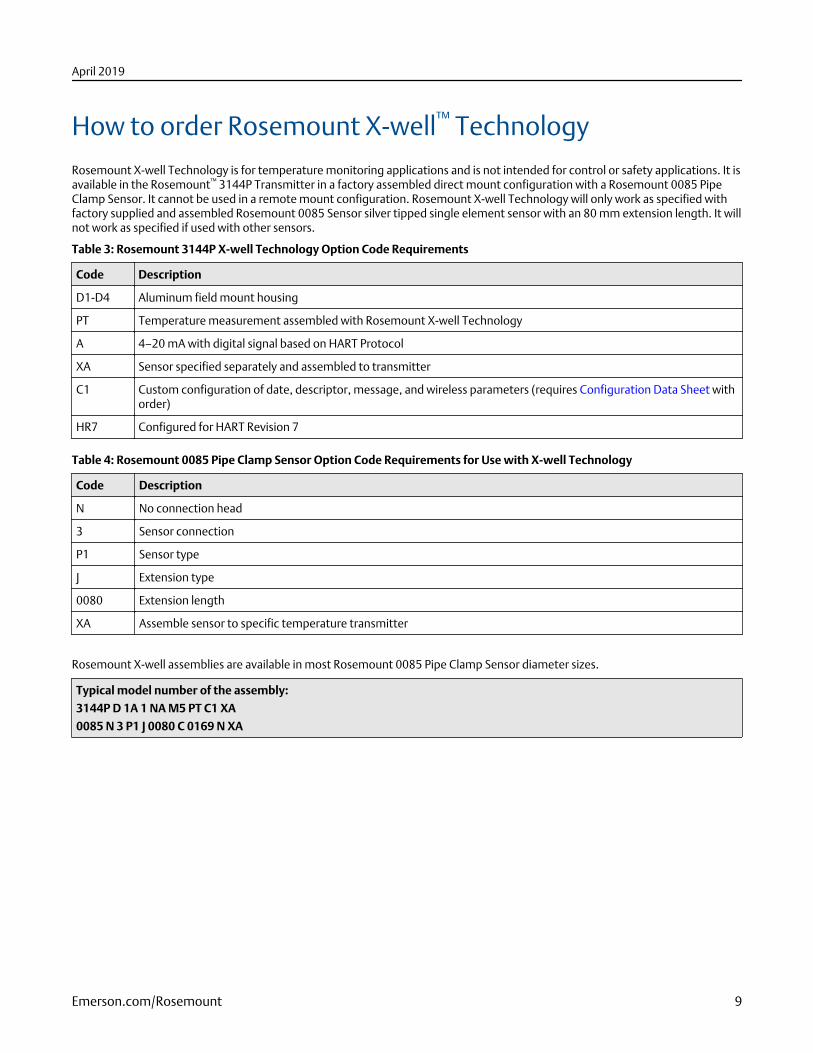
How to order Rosemount X-well™ TechnologyRosemount X-well Technology is for temperature monitoring applications and is not intended for control or safety applications. It isavailable in the Rosemount™ 3144P Transmitter in a factory assembled direct mount configuration with a Rosemount 0085 PipeClamp Sensor. It cannot be used in a remote mount configuration. Rosemount X-well Technology will only work as specified withfactory supplied and assembled Rosemount 0085 Sensor silver tipped single element sensor with an 80 mm extension length. It willnot work as specified if used with other sensors.
Table 3: Rosemount 3144P X-well Technology Option Code Requirements
Code Description
D1-D4 Aluminum field mount housing
PT Temperature measurement assembled with Rosemount X-well Technology
A 4–20 mA with digital signal based on HART Protocol
XA Sensor specified separately and assembled to transmitter
C1 Custom configuration of date, descriptor, message, and wireless parameters (requires Configuration Data Sheet withorder)
HR7 Configured for HART Revision 7
Table 4: Rosemount 0085 Pipe Clamp Sensor Option Code Requirements for Use with X-well Technology
Code Description
N No connection head
3 Sensor connection
P1 Sensor type
J Extension type
0080 Extension length
XA Assemble sensor to specific temperature transmitter
Rosemount X-well assemblies are available in most Rosemount 0085 Pipe Clamp Sensor diameter sizes.
Typical model number of the assembly:
3144P D 1A 1 NA M5 PT C1 XA
0085 N 3 P1 J 0080 C 0169 N XA
April 2019
Emerson.com/Rosemount 9
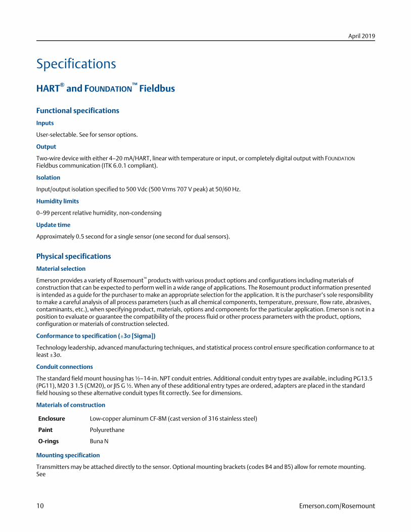
Specifications
HART® and FOUNDATION™ Fieldbus
Functional specifications
Inputs
User-selectable. See for sensor options.
Output
Two-wire device with either 4–20 mA/HART, linear with temperature or input, or completely digital output with FOUNDATION
Fieldbus communication (ITK 6.0.1 compliant).
Isolation
Input/output isolation specified to 500 Vdc (500 Vrms 707 V peak) at 50/60 Hz.
Humidity limits
0–99 percent relative humidity, non-condensing
Update time
Approximately 0.5 second for a single sensor (one second for dual sensors).
Physical specifications
Material selection
Emerson provides a variety of Rosemount™ products with various product options and configurations including materials ofconstruction that can be expected to perform well in a wide range of applications. The Rosemount product information presentedis intended as a guide for the purchaser to make an appropriate selection for the application. It is the purchaser’s sole responsibilityto make a careful analysis of all process parameters (such as all chemical components, temperature, pressure, flow rate, abrasives,contaminants, etc.), when specifying product, materials, options and components for the particular application. Emerson is not in aposition to evaluate or guarantee the compatibility of the process fluid or other process parameters with the product, options,configuration or materials of construction selected.
Conformance to specification (±3σ [Sigma])
Technology leadership, advanced manufacturing techniques, and statistical process control ensure specification conformance to atleast ±3σ.
Conduit connections
The standard field mount housing has ½–14-in. NPT conduit entries. Additional conduit entry types are available, including PG13.5(PG11), M20 3 1.5 (CM20), or JIS G ½. When any of these additional entry types are ordered, adapters are placed in the standardfield housing so these alternative conduit types fit correctly. See for dimensions.
Materials of construction
Enclosure Low-copper aluminum CF-8M (cast version of 316 stainless steel)
Paint Polyurethane
O-rings Buna N
Mounting specification
Transmitters may be attached directly to the sensor. Optional mounting brackets (codes B4 and B5) allow for remote mounting.See
April 2019
10 Emerson.com/Rosemount
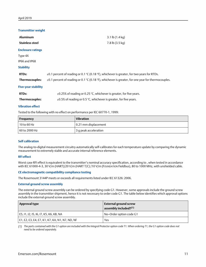
Transmitter weight
Aluminum 3.1 lb (1.4 kg)
Stainless steel 7.8 lb (3.5 kg)
Enclosure ratings
Type 4X
IP66 and IP68
Stability
RTDs: ±0.1 percent of reading or 0.1 °C (0.18 °F), whichever is greater, for two years for RTDs.
Thermocouples: ±0.1 percent of reading or 0.1 °C (0.18 °F), whichever is greater, for one year for thermocouples.
Five-year stability
RTDs: ±0.25% of reading or 0.25 °C, whichever is greater, for five years.
Thermocouples: ±0.5% of reading or 0.5 °C, whichever is greater, for five years.
Vibration effect
Tested to the following with no effect on performance per IEC 60770-1, 1999:
Frequency Vibration
10 to 60 Hz 0.21 mm displacement
60 to 2000 Hz 3 g peak acceleration
Self calibration
The analog-to-digital measurement circuitry automatically self-calibrates for each temperature update by comparing the dynamicmeasurement to extremely stable and accurate internal reference elements.
RFI effect
Worst case RFI effect is equivalent to the transmitter’s nominal accuracy specification, according to , when tested in accordancewith IEC 61000-4-3, 30 V/m (HART)/20 V/m (HART T/C) /10 V/m (FOUNDATION Fieldbus), 80 to 1000 MHz, with unshielded cable.
CE electromagnetic compatibility compliance testing
The Rosemount 3144P meets or exceeds all requirements listed under IEC 61326: 2006.
External ground screw assembly
The external ground screw assembly can be ordered by specifying code G1. However, some approvals include the ground screwassembly in the transmitter shipment, hence it is not necessary to order code G1. The table below identifies which approval optionsinclude the external ground screw assembly.
Approval type External ground screw
assembly included?(1)
E5, I1, I2, I5, I6, I7, K5, K6, KB, NA No–Order option code G1
E1, E2, E3, E4, E7, K1, K7, KA, N1, N7, ND, NF Yes
(1) The parts contained with the G1 option are included with the Integral Protector option code T1. When ordering T1, the G1 option code does notneed to be ordered separately.
April 2019
Emerson.com/Rosemount 11
Hardware tag
■ No charge
■ Two lines of 28 characters (56 characters total)
■ Tags are stainless steel
■ Permanently attached to transmitter
■ Character height is 1/16-in. (1.6 mm)
■ A wire-on tag is available upon request. Five lines of 12 characters (60 characters total)
Software tag
■ HART® transmitter can store up to eight characters in HART 5 mode and 32 characters in HART 7 mode. FOUNDATION Fieldbustransmitters can store up to 32 characters.
■ Can be ordered with different software and hardware tags.
■ If no software tag characters are specified, the first eight characters of the hardware tag are the default.
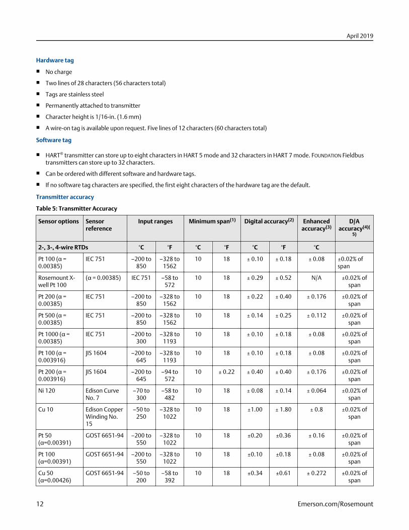
Transmitter accuracy
Table 5: Transmitter Accuracy
Sensor options Sensorreference
Input ranges Minimum span(1) Digital accuracy(2) Enhancedaccuracy(3)
D/Aaccuracy(4)(
5)
2-, 3-, 4-wire RTDs °C °F °C °F °C °F °C
Pt 100 (α =0.00385)
IEC 751 –200 to850
–328 to1562
10 18 ± 0.10 ± 0.18 ± 0.08 ±0.02% ofspan
Rosemount X-well Pt 100
(α = 0.00385) IEC 751 –58 to572
10 18 ± 0.29 ± 0.52 N/A ±0.02% ofspan
Pt 200 (α =0.00385)
IEC 751 –200 to850
–328 to1562
10 18 ± 0.22 ± 0.40 ± 0.176 ±0.02% ofspan
Pt 500 (α =0.00385)
IEC 751 –200 to850
–328 to1562
10 18 ± 0.14 ± 0.25 ± 0.112 ±0.02% ofspan
Pt 1000 (α =0.00385)
IEC 751 –200 to300
–328 to1193
10 18 ± 0.10 ± 0.18 ± 0.08 ±0.02% ofspan
Pt 100 (α =0.003916)
JIS 1604 –200 to645
–328 to1193
10 18 ± 0.10 ± 0.18 ± 0.08 ±0.02% ofspan
Pt 200 (α =0.003916)
JIS 1604 –200 to645
–94 to572
10 ± 0.22 ± 0.40 ± 0.40 ± 0.176 ±0.02% ofspan
Ni 120 Edison CurveNo. 7
–70 to300
–58 to482
10 18 ± 0.08 ± 0.14 ± 0.064 ±0.02% ofspan
Cu 10 Edison CopperWinding No.15
–50 to250
–328 to1022
10 18 ±1.00 ± 1.80 ± 0.8 ±0.02% ofspan
Pt 50(α=0.00391)
GOST 6651-94 –200 to550
–328 to1022
10 18 ±0.20 ±0.36 ± 0.16 ±0.02% ofspan
Pt 100(α=0.00391)
GOST 6651-94 –200 to550
–328 to1022
10 18 ±0.10 ±0.18 ± 0.08 ±0.02% ofspan
Cu 50(α=0.00426)
GOST 6651-94 –50 to200
–58 to392
10 18 ±0.34 ±0.61 ± 0.272 ±0.02% ofspan
April 2019
12 Emerson.com/Rosemount
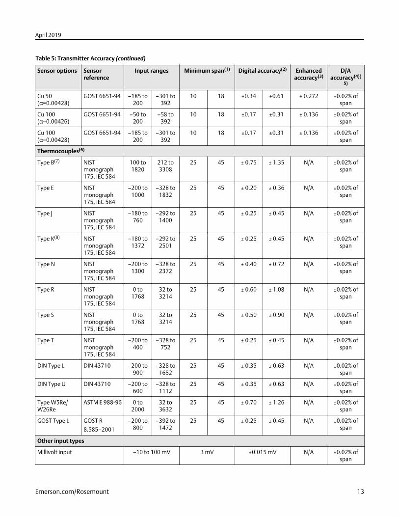
Table 5: Transmitter Accuracy (continued)
Sensor options Sensorreference
Input ranges Minimum span(1) Digital accuracy(2) Enhancedaccuracy(3)
D/Aaccuracy(4)(
5)
Cu 50(α=0.00428)
GOST 6651-94 –185 to200
–301 to392
10 18 ±0.34 ±0.61 ± 0.272 ±0.02% ofspan
Cu 100(α=0.00426)
GOST 6651-94 –50 to200
–58 to392
10 18 ±0.17 ±0.31 ± 0.136 ±0.02% ofspan
Cu 100(α=0.00428)
GOST 6651-94 –185 to200
–301 to392
10 18 ±0.17 ±0.31 ± 0.136 ±0.02% ofspan
Thermocouples(6)
Type B(7) NISTmonograph175, IEC 584
100 to1820
212 to3308
25 45 ± 0.75 ± 1.35 N/A ±0.02% ofspan
Type E NISTmonograph175, IEC 584
–200 to1000
–328 to1832
25 45 ± 0.20 ± 0.36 N/A ±0.02% ofspan
Type J NISTmonograph175, IEC 584
–180 to760
–292 to1400
25 45 ± 0.25 ± 0.45 N/A ±0.02% ofspan
Type K(8) NISTmonograph175, IEC 584
–180 to1372
–292 to2501
25 45 ± 0.25 ± 0.45 N/A ±0.02% ofspan
Type N NISTmonograph175, IEC 584
–200 to1300
–328 to2372
25 45 ± 0.40 ± 0.72 N/A ±0.02% ofspan
Type R NISTmonograph175, IEC 584
0 to1768
32 to3214
25 45 ± 0.60 ± 1.08 N/A ±0.02% ofspan
Type S NISTmonograph175, IEC 584
0 to1768
32 to3214
25 45 ± 0.50 ± 0.90 N/A ±0.02% ofspan
Type T NISTmonograph175, IEC 584
–200 to400
–328 to752
25 45 ± 0.25 ± 0.45 N/A ±0.02% ofspan
DIN Type L DIN 43710 –200 to900
–328 to1652
25 45 ± 0.35 ± 0.63 N/A ±0.02% ofspan
DIN Type U DIN 43710 –200 to600
–328 to1112
25 45 ± 0.35 ± 0.63 N/A ±0.02% ofspan
Type W5Re/W26Re
ASTM E 988-96 0 to2000
32 to3632
25 45 ± 0.70 ± 1.26 N/A ±0.02% ofspan
GOST Type L GOST R
8.585–2001
–200 to800
–392 to1472
25 45 ± 0.25 ± 0.45 N/A ±0.02% ofspan
Other input types
Millivolt input –10 to 100 mV 3 mV ±0.015 mV N/A ±0.02% ofspan
April 2019
Emerson.com/Rosemount 13
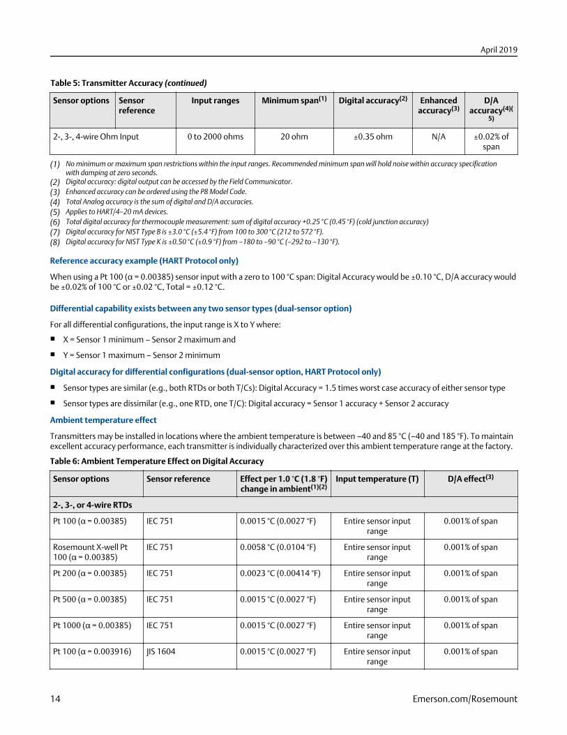
Table 5: Transmitter Accuracy (continued)
Sensor options Sensorreference
Input ranges Minimum span(1) Digital accuracy(2) Enhancedaccuracy(3)
D/Aaccuracy(4)(
5)
2-, 3-, 4-wire Ohm Input 0 to 2000 ohms 20 ohm ±0.35 ohm N/A ±0.02% ofspan
(1) No minimum or maximum span restrictions within the input ranges. Recommended minimum span will hold noise within accuracy specificationwith damping at zero seconds.
(2) Digital accuracy: digital output can be accessed by the Field Communicator.(3) Enhanced accuracy can be ordered using the P8 Model Code.(4) Total Analog accuracy is the sum of digital and D/A accuracies.(5) Applies to HART/4–20 mA devices.(6) Total digital accuracy for thermocouple measurement: sum of digital accuracy +0.25 °C (0.45 °F) (cold junction accuracy)(7) Digital accuracy for NIST Type B is ±3.0 °C (±5.4 °F) from 100 to 300 °C (212 to 572 °F).(8) Digital accuracy for NIST Type K is ±0.50 °C (±0.9 °F) from –180 to –90 °C (–292 to –130 °F).
Reference accuracy example (HART Protocol only)
When using a Pt 100 (α = 0.00385) sensor input with a zero to 100 °C span: Digital Accuracy would be ±0.10 °C, D/A accuracy wouldbe ±0.02% of 100 °C or ±0.02 °C, Total = ±0.12 °C.
Differential capability exists between any two sensor types (dual-sensor option)
For all differential configurations, the input range is X to Y where:
■ X = Sensor 1 minimum – Sensor 2 maximum and
■ Y = Sensor 1 maximum – Sensor 2 minimum
Digital accuracy for differential configurations (dual-sensor option, HART Protocol only)
■ Sensor types are similar (e.g., both RTDs or both T/Cs): Digital Accuracy = 1.5 times worst case accuracy of either sensor type
■ Sensor types are dissimilar (e.g., one RTD, one T/C): Digital accuracy = Sensor 1 accuracy + Sensor 2 accuracy
Ambient temperature effect
Transmitters may be installed in locations where the ambient temperature is between –40 and 85 °C (–40 and 185 °F). To maintainexcellent accuracy performance, each transmitter is individually characterized over this ambient temperature range at the factory.
Table 6: Ambient Temperature Effect on Digital Accuracy
Sensor options Sensor reference Effect per 1.0 °C (1.8 °F)change in ambient(1)(2)
Input temperature (T) D/A effect(3)
2-, 3-, or 4-wire RTDs
Pt 100 (α = 0.00385) IEC 751 0.0015 °C (0.0027 °F) Entire sensor inputrange
0.001% of span
Rosemount X-well Pt100 (α = 0.00385)
IEC 751 0.0058 °C (0.0104 °F) Entire sensor inputrange
0.001% of span
Pt 200 (α = 0.00385) IEC 751 0.0023 °C (0.00414 °F) Entire sensor inputrange
0.001% of span
Pt 500 (α = 0.00385) IEC 751 0.0015 °C (0.0027 °F) Entire sensor inputrange
0.001% of span
Pt 1000 (α = 0.00385) IEC 751 0.0015 °C (0.0027 °F) Entire sensor inputrange
0.001% of span
Pt 100 (α = 0.003916) JIS 1604 0.0015 °C (0.0027 °F) Entire sensor inputrange
0.001% of span
April 2019
14 Emerson.com/Rosemount
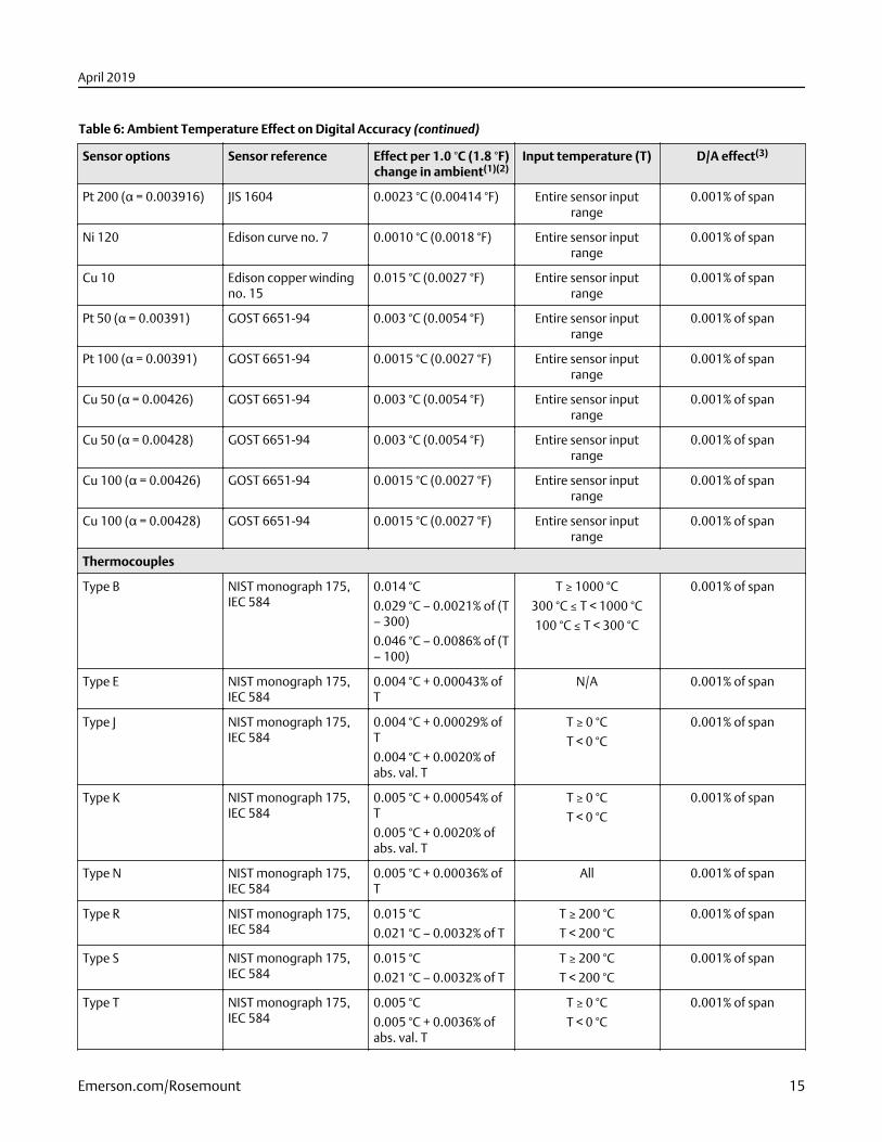
Table 6: Ambient Temperature Effect on Digital Accuracy (continued)
Sensor options Sensor reference Effect per 1.0 °C (1.8 °F)change in ambient(1)(2)
Input temperature (T) D/A effect(3)
Pt 200 (α = 0.003916) JIS 1604 0.0023 °C (0.00414 °F) Entire sensor inputrange
0.001% of span
Ni 120 Edison curve no. 7 0.0010 °C (0.0018 °F) Entire sensor inputrange
0.001% of span
Cu 10 Edison copper windingno. 15
0.015 °C (0.0027 °F) Entire sensor inputrange
0.001% of span
Pt 50 (α = 0.00391) GOST 6651-94 0.003 °C (0.0054 °F) Entire sensor inputrange
0.001% of span
Pt 100 (α = 0.00391) GOST 6651-94 0.0015 °C (0.0027 °F) Entire sensor inputrange
0.001% of span
Cu 50 (α = 0.00426) GOST 6651-94 0.003 °C (0.0054 °F) Entire sensor inputrange
0.001% of span
Cu 50 (α = 0.00428) GOST 6651-94 0.003 °C (0.0054 °F) Entire sensor inputrange
0.001% of span
Cu 100 (α = 0.00426) GOST 6651-94 0.0015 °C (0.0027 °F) Entire sensor inputrange
0.001% of span
Cu 100 (α = 0.00428) GOST 6651-94 0.0015 °C (0.0027 °F) Entire sensor inputrange
0.001% of span
Thermocouples
Type B NIST monograph 175,IEC 584
0.014 °C
0.029 °C – 0.0021% of (T– 300)
0.046 °C – 0.0086% of (T– 100)
T ≥ 1000 °C
300 °C ≤ T < 1000 °C
100 °C ≤ T < 300 °C
0.001% of span
Type E NIST monograph 175,IEC 584
0.004 °C + 0.00043% ofT
N/A 0.001% of span
Type J NIST monograph 175,IEC 584
0.004 °C + 0.00029% ofT
0.004 °C + 0.0020% ofabs. val. T
T ≥ 0 °C
T < 0 °C
0.001% of span
Type K NIST monograph 175,IEC 584
0.005 °C + 0.00054% ofT
0.005 °C + 0.0020% ofabs. val. T
T ≥ 0 °C
T < 0 °C
0.001% of span
Type N NIST monograph 175,IEC 584
0.005 °C + 0.00036% ofT
All 0.001% of span
Type R NIST monograph 175,IEC 584
0.015 °C
0.021 °C – 0.0032% of T
T ≥ 200 °C
T < 200 °C
0.001% of span
Type S NIST monograph 175,IEC 584
0.015 °C
0.021 °C – 0.0032% of T
T ≥ 200 °C
T < 200 °C
0.001% of span
Type T NIST monograph 175,IEC 584
0.005 °C
0.005 °C + 0.0036% ofabs. val. T
T ≥ 0 °C
T < 0 °C
0.001% of span
April 2019
Emerson.com/Rosemount 15
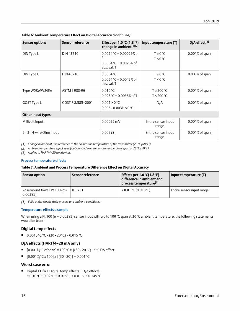
Table 6: Ambient Temperature Effect on Digital Accuracy (continued)
Sensor options Sensor reference Effect per 1.0 °C (1.8 °F)change in ambient(1)(2)
Input temperature (T) D/A effect(3)
DIN Type L DIN 43710 0.0054 °C + 0.00029% ofR
0.0054 °C + 0.0025% ofabs. val. T
T ≥ 0 °C
T < 0 °C
0.001% of span
DIN Type U DIN 43710 0.0064 °C
0.0064 °C + 0.0043% ofabs. val. T
T ≥ 0 °C
T < 0 °C
0.001% of span
Type W5Re/W26Re ASTM E 988-96 0.016 °C
0.023 °C + 0.0036% of T
T ≥ 200 °C
T < 200 °C
0.001% of span
GOST Type L GOST R 8.585–2001 0.005 > 0 °C
0.005 - 0.003% < 0 °C
N/A 0.001% of span
Other input types
Millivolt Input 0.00025 mV Entire sensor inputrange
0.001% of span
2-, 3-, 4-wire Ohm Input 0.007 Ω Entire sensor inputrange
0.001% of span
(1) Change in ambient is in reference to the calibration temperature of the transmitter (20 °C [68 °F]).(2) Ambient temperature effect specification valid over minimum temperature span of 28 °C (50 °F).(3) Applies to HART/4–20 mA devices.
Process temperature effects
Table 7: Ambient and Process Temperature Difference Effect on Digital Accuracy
Sensor option Sensor reference Effects per 1.0 °C(1.8 °F)difference in ambient andprocess temperature(1)
Input temperature (T)
Rosemount X-well Pt 100 (α =0.00385)
IEC 751 ± 0.01 °C (0.018 °F) Entire sensor input range
(1) Valid under steady state process and ambient conditions.
Temperature effects example
When using a Pt 100 (α = 0.00385) sensor input with a 0 to 100 °C span at 30 °C ambient temperature, the following statementswould be true:
Digital temp effects■ 0.0015 °C/°C x (30 - 20 °C) = 0.015 °C
D/A effects (HART/4–20 mA only)■ [0.001%/°C of span] x 100 °C x |(30 - 20 °C)| = °C DA effect
■ [0.001%/°C x 100] x |(30 - 20)| = 0.001 °C
Worst case error■ Digital + D/A + Digital temp effects + D/A effects
= 0.10 °C + 0.02 °C + 0.015 °C + 0.01 °C = 0.145 °C
April 2019
16 Emerson.com/Rosemount
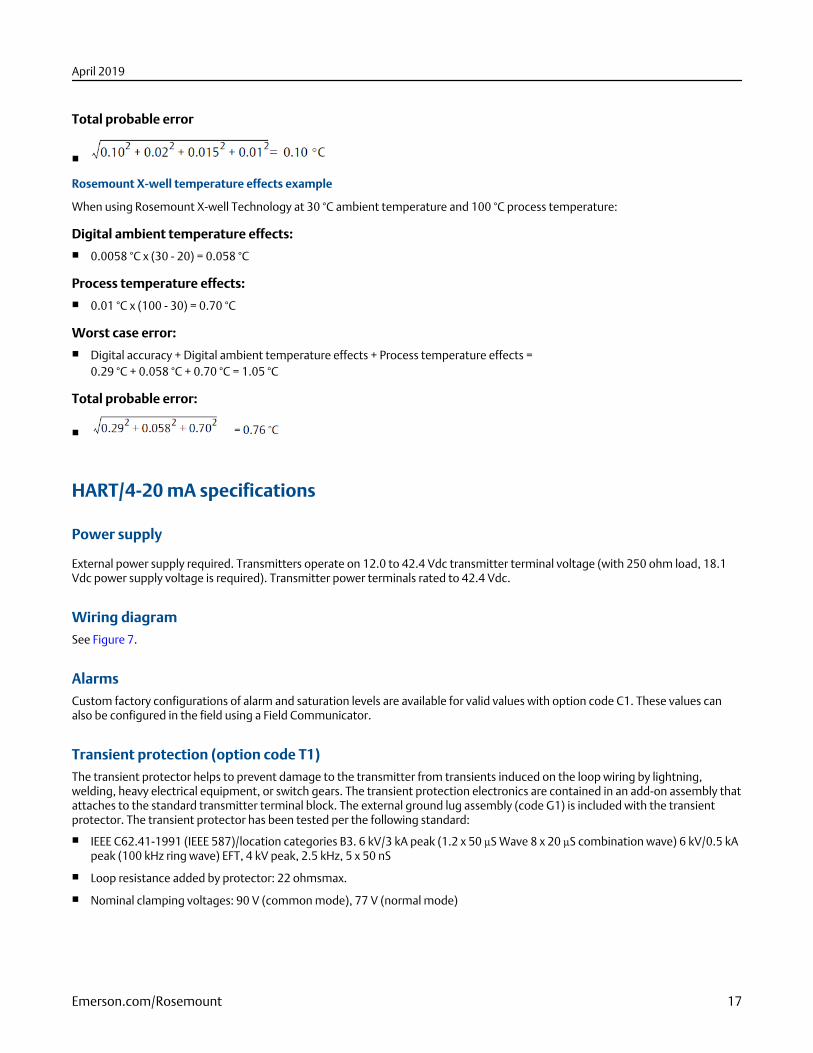
Total probable error
■
Rosemount X-well temperature effects example
When using Rosemount X-well Technology at 30 °C ambient temperature and 100 °C process temperature:
Digital ambient temperature effects:■ 0.0058 °C x (30 - 20) = 0.058 °C
Process temperature effects:■ 0.01 °C x (100 - 30) = 0.70 °C
Worst case error:■ Digital accuracy + Digital ambient temperature effects + Process temperature effects =
0.29 °C + 0.058 °C + 0.70 °C = 1.05 °C
Total probable error:
■
HART/4-20 mA specifications
Power supply
External power supply required. Transmitters operate on 12.0 to 42.4 Vdc transmitter terminal voltage (with 250 ohm load, 18.1Vdc power supply voltage is required). Transmitter power terminals rated to 42.4 Vdc.
Wiring diagramSee Figure 7.
AlarmsCustom factory configurations of alarm and saturation levels are available for valid values with option code C1. These values canalso be configured in the field using a Field Communicator.
Transient protection (option code T1)The transient protector helps to prevent damage to the transmitter from transients induced on the loop wiring by lightning,welding, heavy electrical equipment, or switch gears. The transient protection electronics are contained in an add-on assembly thatattaches to the standard transmitter terminal block. The external ground lug assembly (code G1) is included with the transientprotector. The transient protector has been tested per the following standard:
■ IEEE C62.41-1991 (IEEE 587)/location categories B3. 6 kV/3 kA peak (1.2 x 50 μS Wave 8 x 20 μS combination wave) 6 kV/0.5 kApeak (100 kHz ring wave) EFT, 4 kV peak, 2.5 kHz, 5 x 50 nS
■ Loop resistance added by protector: 22 ohmsmax.
■ Nominal clamping voltages: 90 V (common mode), 77 V (normal mode)
April 2019
Emerson.com/Rosemount 17
Local displayOptional five-digit LCD display includes 0–100% bar graph. Digits are 0.4 inches (8mm) high. Display options include engineeringunits (°F, °C, °R, K, ohms, and millivolts), percent, and milliamperes. The display can also be set to alternate between engineeringunits/milliamperes, Sensor 1/Sensor 2, Sensor 1/Sensor 2/Differential Temperature, and Sensor 1/Sensor2/Average Temperature.All display options, including the decimal point, may be reconfigured in the field using a Field Communicator or AMS DeviceManager.
Turn-on timePerformance within specifications is achieved less than six seconds after power is applied to the transmitter when the dampingvalue is set to zero seconds.
Power supply effectLess than ±0.005 percent of span per volt.
SIS safety transmitter failure valuesIEC 61508 Safety Certified SIL 2 and SIL 3 Claim Limit
■ Safety accuracy: Span ≥ 100 °C: ±2% of process variable span
■ Span < 100 °C: ±2 °C
■ Safety response time: five seconds
■ Safety specifications and FMEDA report available at Emerson.com/Rosemount/Safety
■ Software suitable for SIL3 applications
Temperature limitsTable 8: Temperature Limits
Description Operating limit Storage limit
Without LCD display –40 to 185 °F
–40 to 85 °C
–76 to 250 °F
–60 to 120 °C
With LCD display(1) –40 to 185 °F
–40 to 85 °C
–76 to 185 °F
–60 to 85 °C
(1) LCD display may not be readable and LCD display updates will be slower at temperatures below –4 °F (–20 °C).
Field Communicator connectionsField Communicator connections are permanently fixed to power/signal block.
Failure modeThe Rosemount 3144P features software and hardware failure mode detection. An independent circuit is designed to providebackup alarm output if the microprocessor hardware or software fails.
The alarm level is user-selectable using the failure mode switch. If failure occurs, the position of the hardware switch determinesthe direction in which the output is driven (HIGH or LOW). The switch feeds into the digital-to-analog (D/A) converter, which drivesthe proper alarm output even if the microprocessor fails. The values at which the transmitter drives its output in failure modedepends on whether it is configured to standard, or NAMUR-compliant (NAMUR recommendation NE 43) operation. The values forstandard and NAMUR-compliant operation are as follows:
April 2019
18 Emerson.com/Rosemount
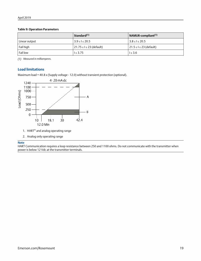
Table 9: Operation Parameters
Standard(1) NAMUR-compliant(1)
Linear output 3.9 ≤ I ≤ 20.5 3.8 ≤ I ≤ 20.5
Fail high 21.75 ≤ I ≤ 23 (default) 21.5 ≤ I ≤ 23 (default)
Fail low I ≤ 3.75 I ≤ 3.6
(1) Measured in milliamperes.
Load limitationsMaximum load = 40.8 x (Supply voltage - 12.0) without transient protection (optional).
1. HART® and analog operating range
2. Analog only operating range
NoteHART Communication requires a loop resistance between 250 and 1100 ohms. Do not communicate with the transmitter whenpower is below 12 Vdc at the transmitter terminals.
April 2019
Emerson.com/Rosemount 19
FOUNDATION™ Fieldbus specifications
FOUNDATION Fieldbus device registrationDevice tested and registered to ITK 6.0.1
Power SupplyPowered over FOUNDATION Fieldbus with standard Fieldbus power supplies. Transmitters operate on 9.0 to 32.0 Vdc, 12 mAmaximum. Transmitter power terminals are rated to 42.4 Vdc.
Wiring diagramSee Figure 8
AlarmThe AI function block allows the user to configure the alarms to HIGH-HIGH, HIGH, LOW, or LOW-LOW with a variety of prioritylevels and hysteresis settings.
Transient protection (option code T1)The transient protector helps to prevent damage to the transmitter from transients induced on the loop wiring by lightning,welding, heavy electrical equipment, or switch gears. The transient protection electronics are contained in an add-on assembly thatattaches to the standard transmitter terminal block. The transient terminal block is not polarity insensitive. The transient protectorhas been tested to the following standard:
■ IEEE C62.41-1991 (IEEE 587)/Location Categories B3. 6 kV/3 kA peak (1.2 x 50 μS Wave 8 x 20 μS Combination Wave) 6 kV/0.5kA peak (100 kHz Ring Wave) EFT, 4 kV peak, 2.5 kHz, 5*50 nS
■ Loop resistance added by protector: 22 ohmsmaximum
■ Nominal clamping voltages: 90 V (common mode), 77 V (normal mode)
Diagnostics suite for FOUNDATION Fieldbus (option code D01)The Rosemount 3144P Diagnostics Suite for FOUNDATION Fieldbus provides advanced functionality in the form of StatisticalProcess Monitoring (SPM), a thermocouple diagnostic, and sensor drift alert. SPM technology calculates the mean and standarddeviation of the process variable and makes them available to the user. This may be used to detect abnormal process situations.
The thermocouple diagnostic enables the transmitter to measure and monitor the resistance of thermocouple loops in order todetect drift or changing wiring connections.
Sensor drift alert allows the user to monitor the difference in measurement between two sensors installed in one process point. Achange in this differential value may indicate drifting sensors.
Local displayDisplays all DS_65 measurements in the Transducer and Function Blocks including Sensor 1, Sensor 2, differential, and terminaltemperatures. The display alternates up to four selected items. The meter can display up to five digits in engineering units (°F, °C,°R, K, Ω, and millivolts). Display settings are configured at the factory according to the transmitter configuration (standard orcustom). These settings can be reconfigured in the field using a Field Communicator or DeltaV. In addition, the LCD displayprovides the ability to display DS_65 parameters from other devices. In addition to the configuration of the meter, sensordiagnostic data is displayed. If the measurement status is Good, the measured value is shown. If the measurement status isUncertain, the status indicating uncertain is shown in addition to the measured value. If the measurement status is Bad, the reasonfor the bad measurement is shown.
NoteWhen ordering a spare electronics module assembly, the LCD display transducer block will display the default parameter.
April 2019
20 Emerson.com/Rosemount
Turn-on timePerformance within specifications is achieved less than 20 seconds after power is applied to the transmitter when the dampingvalue is set to zero seconds.
StatusThe device is compliant to NAMUR NE 107, ensuring consistent, reliable and standardized device diagnostic information.
The new standard is designed to improve the way device status and diagnostic information is communicated to operators andmaintenance personnel in order to increase productivity and reduce costs.
If self-diagnostics detect a sensor burnout or a transmitter failure, the status of the measurement will be updated accordingly. Thestatus may also send the PID output to a safe value.
FOUNDATION Fieldbus parameters
Schedule entries 25 (max)
Links 30 (max)
Virtual Communications Relationships (VCR) 20 (max)
Function blocks■ All blocks will ship with unique block names, e.g. AI_1400_XXXX.
■ All blocks shall be instantiated to avoid invalid defaults.
■ All Rosemount 3144P FF have parameter COMPATIBILITY_REV for backward compatibility.
■ Parameters will be initialized to common values for easier bench configuration.
■ All default block tags are less than or equal to 16 characters in length to avoid inconvenience of apparently identical tags.
■ Default block tags include underscores, “_”, instead of whitespaces for easier configuration.
Resource block■ Contains physical transmitter information including available memory, manufacture identification, device type, software tag,
and unique identification.
■ Plantweb™ Alerts enable the full power of the PW digital architecture by diagnosing instrumentation issues, communicating thedetails, and recommending a solution.
Transducer block■ Contains the actual temperature measurement data, including sensor 1, sensor 2, and terminal temperature.
■ Includes information about sensor type and configuration, engineering units, linearization, range, damping, and diagnostics.
■ Device Revision 3 and above includes Hot Backup functionality in the transducer block.
LCD display block (when an LCD display is used)■ Configures the local display.
Analog input (AI)■ Processes the measurement and makes it available on the Fieldbus segment.
■ Allows filtering, engineering unit, and alarm changes.
■ All devices ship with the AI blocks scheduled, meaning no configuration is needed if the factory default channels are used.
April 2019
Emerson.com/Rosemount 21
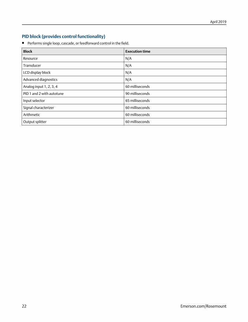
PID block (provides control functionality)■ Performs single loop, cascade, or feedforward control in the field.
Block Execution time
Resource N/A
Transducer N/A
LCD display block N/A
Advanced diagnostics N/A
Analog input 1, 2, 3, 4 60 milliseconds
PID 1 and 2 with autotune 90 milliseconds
Input selector 65 milliseconds
Signal characterizer 60 milliseconds
Arithmetic 60 milliseconds
Output splitter 60 milliseconds
April 2019
22 Emerson.com/Rosemount
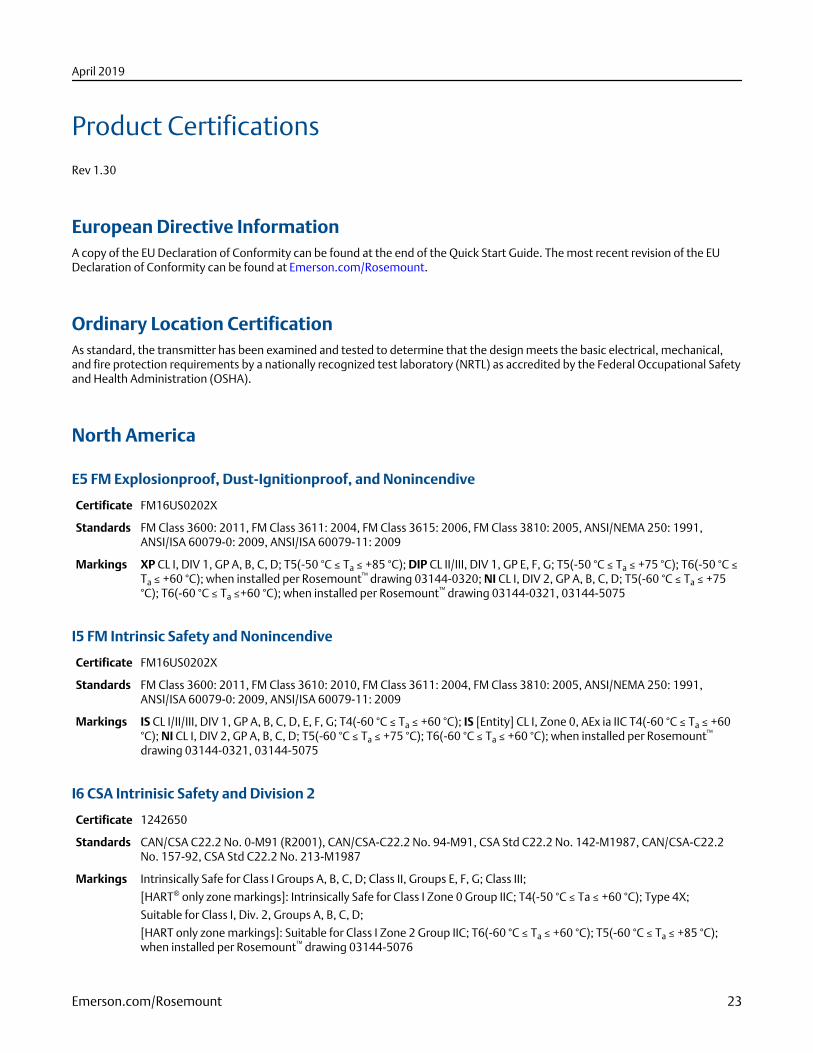
Product CertificationsRev 1.30
European Directive InformationA copy of the EU Declaration of Conformity can be found at the end of the Quick Start Guide. The most recent revision of the EUDeclaration of Conformity can be found at Emerson.com/Rosemount.
Ordinary Location CertificationAs standard, the transmitter has been examined and tested to determine that the design meets the basic electrical, mechanical,and fire protection requirements by a nationally recognized test laboratory (NRTL) as accredited by the Federal Occupational Safetyand Health Administration (OSHA).
North America
E5 FM Explosionproof, Dust-Ignitionproof, and Nonincendive
Certificate FM16US0202X
Standards FM Class 3600: 2011, FM Class 3611: 2004, FM Class 3615: 2006, FM Class 3810: 2005, ANSI/NEMA 250: 1991,ANSI/ISA 60079-0: 2009, ANSI/ISA 60079-11: 2009
Markings XP CL I, DIV 1, GP A, B, C, D; T5(-50 °C ≤ Ta ≤ +85 °C); DIP CL II/III, DIV 1, GP E, F, G; T5(-50 °C ≤ Ta ≤ +75 °C); T6(-50 °C ≤Ta ≤ +60 °C); when installed per Rosemount™ drawing 03144-0320; NI CL I, DIV 2, GP A, B, C, D; T5(-60 °C ≤ Ta ≤ +75°C); T6(-60 °C ≤ Ta ≤+60 °C); when installed per Rosemount™ drawing 03144-0321, 03144-5075
I5 FM Intrinsic Safety and Nonincendive
Certificate FM16US0202X
Standards FM Class 3600: 2011, FM Class 3610: 2010, FM Class 3611: 2004, FM Class 3810: 2005, ANSI/NEMA 250: 1991,ANSI/ISA 60079-0: 2009, ANSI/ISA 60079-11: 2009
Markings IS CL I/II/III, DIV 1, GP A, B, C, D, E, F, G; T4(-60 °C ≤ Ta ≤ +60 °C); IS [Entity] CL I, Zone 0, AEx ia IIC T4(-60 °C ≤ Ta ≤ +60°C); NI CL I, DIV 2, GP A, B, C, D; T5(-60 °C ≤ Ta ≤ +75 °C); T6(-60 °C ≤ Ta ≤ +60 °C); when installed per Rosemount™
drawing 03144-0321, 03144-5075
I6 CSA Intrinisic Safety and Division 2
Certificate 1242650
Standards CAN/CSA C22.2 No. 0-M91 (R2001), CAN/CSA-C22.2 No. 94-M91, CSA Std C22.2 No. 142-M1987, CAN/CSA-C22.2No. 157-92, CSA Std C22.2 No. 213-M1987
Markings Intrinsically Safe for Class I Groups A, B, C, D; Class II, Groups E, F, G; Class III;
[HART® only zone markings]: Intrinsically Safe for Class I Zone 0 Group IIC; T4(-50 °C ≤ Ta ≤ +60 °C); Type 4X;
Suitable for Class I, Div. 2, Groups A, B, C, D;
[HART only zone markings]: Suitable for Class I Zone 2 Group IIC; T6(-60 °C ≤ Ta ≤ +60 °C); T5(-60 °C ≤ Ta ≤ +85 °C);when installed per Rosemount™ drawing 03144-5076
April 2019
Emerson.com/Rosemount 23
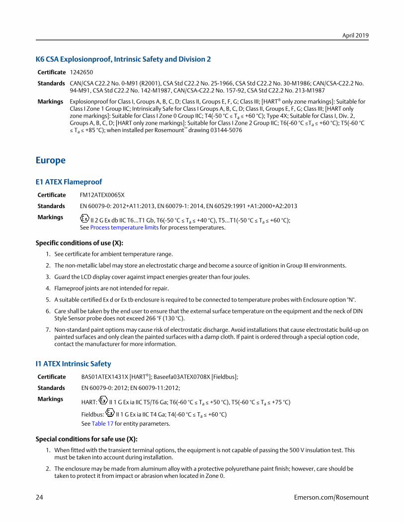
K6 CSA Explosionproof, Intrinsic Safety and Division 2
Certificate 1242650
Standards CAN/CSA C22.2 No. 0-M91 (R2001), CSA Std C22.2 No. 25-1966, CSA Std C22.2 No. 30-M1986; CAN/CSA-C22.2 No.94-M91, CSA Std C22.2 No. 142-M1987, CAN/CSA-C22.2 No. 157-92, CSA Std C22.2 No. 213-M1987
Markings Explosionproof for Class I, Groups A, B, C, D; Class II, Groups E, F, G; Class III; [HART® only zone markings]: Suitable forClass I Zone 1 Group IIC; Intrinsically Safe for Class I Groups A, B, C, D; Class II, Groups E, F, G; Class III; [HART onlyzone markings]: Suitable for Class I Zone 0 Group IIC; T4(-50 °C ≤ Ta ≤ +60 °C); Type 4X; Suitable for Class I, Div. 2,Groups A, B, C, D; [HART only zone markings]: Suitable for Class I Zone 2 Group IIC; T6(-60 °C ≤Ta ≤ +60 °C); T5(-60 °C≤ Ta ≤ +85 °C); when installed per Rosemount™ drawing 03144-5076
Europe
E1 ATEX Flameproof
Certificate FM12ATEX0065X
Standards EN 60079-0: 2012+A11:2013, EN 60079-1: 2014, EN 60529:1991 +A1:2000+A2:2013
Markings II 2 G Ex db IIC T6…T1 Gb, T6(-50 °C ≤ Ta ≤ +40 °C), T5…T1(-50 °C ≤ Ta ≤ +60 °C);See Process temperature limits for process temperatures.
Specific conditions of use (X):
1. See certificate for ambient temperature range.
2. The non-metallic label may store an electrostatic charge and become a source of ignition in Group III environments.
3. Guard the LCD display cover against impact energies greater than four joules.
4. Flameproof joints are not intended for repair.
5. A suitable certified Ex d or Ex tb enclosure is required to be connected to temperature probes with Enclosure option "N".
6. Care shall be taken by the end user to ensure that the external surface temperature on the equipment and the neck of DINStyle Sensor probe does not exceed 266 °F (130 °C).
7. Non-standard paint options may cause risk of electrostatic discharge. Avoid installations that cause electrostatic build-up onpainted surfaces and only clean the painted surfaces with a damp cloth. If paint is ordered through a special option code,contact the manufacturer for more information.
I1 ATEX Intrinsic Safety
Certificate BAS01ATEX1431X [HART®]; Baseefa03ATEX0708X [Fieldbus];
Standards EN 60079-0: 2012; EN 60079-11:2012;
Markings HART: II 1 G Ex ia IIC T5/T6 Ga; T6(-60 °C ≤ Ta ≤ +50 °C), T5(-60 °C ≤ Ta ≤ +75 °C)
Fieldbus: II 1 G Ex ia IIC T4 Ga; T4(-60 °C ≤ Ta ≤ +60 °C)
See Table 17 for entity parameters.
Special conditions for safe use (X):
1. When fitted with the transient terminal options, the equipment is not capable of passing the 500 V insulation test. Thismust be taken into account during installation.
2. The enclosure may be made from aluminum alloy with a protective polyurethane paint finish; however, care should betaken to protect it from impact or abrasion when located in Zone 0.
April 2019
24 Emerson.com/Rosemount
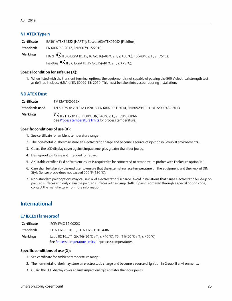
N1 ATEX Type n
Certificate BAS01ATEX3432X [HART®]; Baseefa03ATEX0709X [Fieldbus]
Standards EN 60079-0:2012, EN 60079-15:2010
Markings HART: II 3 G Ex nA IIC T5/T6 Gc; T6(-40 °C ≤ Ta ≤ +50 °C), T5(-40 °C ≤ Ta ≤ +75 °C);
Fieldbus: II 3 G Ex nA IIC T5 Gc; T5(-40 °C ≤ Ta ≤ +75 °C);
Special condition for safe use (X):
1. When fitted with the transient terminal options, the equipment is not capable of passing the 500 V electrical strength testas defined in clause 6.5.1 of EN 60079-15: 2010. This must be taken into account during installation.
ND ATEX Dust
Certificate FM12ATEX0065X
Standards used EN 60079-0: 2012+A11:2013, EN 60079-31:2014, EN 60529:1991 +A1:2000+A2:2013
Markings II 2 D Ex tb IIIC T130°C Db, (-40 °C ≤ Ta ≤ +70 °C); IP66See Process temperature limits for process temperature.
Specific conditions of use (X):
1. See certificate for ambient temperature range.
2. The non-metallic label may store an electrostatic charge and become a source of ignition in Group III environments.
3. Guard the LCD display cover against impact energies greater than four joules.
4. Flameproof joints are not intended for repair.
5. A suitable certified Ex d or Ex tb enclosure is required to be connected to temperature probes with Enclosure option "N".
6. Care shall be taken by the end user to ensure that the external surface temperature on the equipment and the neck of DINStyle Sensor probe does not exceed 266 °F (130 °C).
7. Non-standard paint options may cause risk of electrostatic discharge. Avoid installations that cause electrostatic build-up onpainted surfaces and only clean the painted surfaces with a damp cloth. If paint is ordered through a special option code,contact the manufacturer for more information.
International
E7 IECEx Flameproof
Certificate IECEx FMG 12.0022X
Standards IEC 60079-0:2011, IEC 60079-1:2014-06
Markings Ex db IIC T6…T1 Gb, T6(-50 °C ≤ Ta ≤ +40 °C), T5…T1(-50 °C ≤ Ta ≤ +60 °C)
See Process temperature limits for process temperatures.
Specific conditions of use (X):
1. See certificate for ambient temperature range.
2. The non-metallic label may store an electrostatic charge and become a source of ignition in Group III environments.
3. Guard the LCD display cover against impact energies greater than four joules.
April 2019
Emerson.com/Rosemount 25
4. Flameproof joints are not intended for repair.
5. A suitable certified Ex d or Ex tb enclosure is required to be connected to temperature probes with Enclosure option "N".
6. Care shall be taken by the end user to ensure that the external surface temperature on the equipment and the neck of DINStyle Sensor probe does not exceed 266 °F (130 °C).
7. Non-standard paint options may cause risk of electrostatic discharge. Avoid installations that cause electrostatic build-up onpainted surfaces and only clean the painted surfaces with a damp cloth. If paint is ordered through a special option code,contact the manufacturer for more information.
Additionally available with option K7
IECEx Dust
Certificate: IECEx FMG 12.0022X
Standards: IEC 60079-0:2011 and IEC 60079-31:2013
Markings: Ex tb IIIC T130 °C Db, (-40 °C ≤ Ta ≤ +70 °C); IP66
See Process temperature limits for process temperatures.
Specific conditions of use (X):
1. See certificate for ambient temperature range.
2. The non-metallic label may store an electrostatic charge and become a source of ignition in Group III environments.
3. Guard the LCD display cover against impact energies greater than four joules.
4. Flameproof joints are not intended for repair.
5. A suitable certified Ex d or Ex tb enclosure is required to be connected to temperature probes with Enclosure option "N".
6. Care shall be taken by the end user to ensure that the external surface temperature on the equipment and the neck of DINStyle Sensor probe does not exceed 266 °F (130 °C).
7. Non-standard paint options may cause risk of electrostatic discharge. Avoid installations that cause electrostatic build-up onpainted surfaces and only clean the painted surfaces with a damp cloth. If paint is ordered through a special option code,contact the manufacturer for more information.
I7 IECEx Intrinsic Safety
Certificate IECEx BAS 07.0002X [HART®]; IECEx BAS 07.0004X [Fieldbus]
Standards IEC 60079-0: 2011; IEC 60079-11: 2011;
Markings HART: Ex ia IIC T5/T6 Ga; T6(-60 °C ≤ Ta ≤ +50 °C), T5(-60 °C ≤ Ta ≤ +75 °C);
Fieldbus: Ex ia IIC T4 Ga; T4(-60 °C ≤ Ta ≤ +60 °C)
See Table 17 for entity parameters.
Special conditions for safe use (X):
1. When fitted with the transient terminal options, the equipment is not capable of passing the 500 V electrical strength testas defined in Clause 6.3.13 of IEC 60079-11: 2011. This must be taken into account during installation.
2. The enclosure may be made from aluminum alloy with a protective polyurethane paint finish; however, care should betaken to protect it from impact or abrasion when located in Zone 0.
N7 IECEx Type n
Certificate IECEx BAS 07.0003X [HART®]; IECEx BAS 07.0005X [Fieldbus]
Standards IEC 60079-0:2011, IEC 60079-15:2010
April 2019
26 Emerson.com/Rosemount
Markings HART: Ex nA IIC T5/T6 Gc; T6(-40 °C ≤ Ta ≤ +50 °C), T5(-40 °C ≤ Ta ≤ +75 °C);Fieldbus: Ex nA IIC T5 Gc; T5(-40 °C ≤ Ta ≤ +75 °C);
Special condition for safe use (X):
1. When fitted with the transient terminal options, the equipment is not capable of passing the 500 V electrical strength testas defined in clause 6.5.1 of EN 60079-15: 2010. This must be taken into account during installation.
Brazil
E2 INMETRO Flameproof and Dust
Certificate UL-BR 13.0535X
Standards ABNT NBR IEC 60079-0:2013; ABNT NBR IEC 60079-1:2016; ABNT NBR IEC 60079-31:2014
Markings Ex db IIC T6...T1 Gb; T6(-50 °C ≤ Ta ≤ +40 °C); T5...T1(-50 °C ≤ Ta ≤ +60 °C)Ex tb IIIC T130 °C Db; IP66; (-40 °C ≤ Ta ≤ +70 °C)
Special conditions for safe use (X):
1. See product description for ambient temperature limits and process temperature limits.
2. The non-metallic label may store an electrostatic charge and become a source of ignition in Group III environments.
3. Guard the LCD display cover against impact energies greater than four joules.
4. Consult the manufacturer if dimensional information on the flameproof joints is necessary.
I2 INMETRO Intrinsic Safety [HART®]
Certificate UL-BR 15.0088X
Standards ABNT NBR IEC 60079-0:2008 + Errata 1:2011, ABNT NBR IEC 60079-11:2009
Markings Ex ia IIC T6 Ga (-60 °C < Ta < 50 °C), Ex ia IIC T5 Ga (-60 °C < Ta < 75 °C)
See Table 17 for entity parameters.
Special conditions for safe use (X)
1. When fitted with the transient terminal options, the equipment is not capable of withstanding the 500 V electrical strengthtest as defined in ABNT NBR IEC60079-11. This must be taken into account during installation.
2. The enclosure may be made from aluminum alloy with a protective polyurethane paint finish; however, care should betaken to protect it from impact and abrasion when located in areas that require EPL Ga (Zone 0).
INMETRO Intrinsic Safety [Fieldbus/FISCO]
Certificate UL-BR 15.0030X
Standards ABNT NBR IEC 60079-0:2008 + Errata 1:2011, ABNT NBR IEC 60079-11:2009
Markings Ex ia IIC T4 Ga (-60 °C < Ta < +60 °C)See Table 17 for entity parameters.
Special conditions for safe use (X)
1. When fitted with the transient terminal options, the equipment is not capable of withstanding the 500 V electrical strengthtest as defined in ABNT NBR IEC60079-11. This must be taken into account during installation.
2. The enclosure may be made from aluminum alloy with a protective polyurethane paint finish; however, care should betaken to protect it from impact and abrasion when located in areas that require EPL Ga (Zone 0).
April 2019
Emerson.com/Rosemount 27
China
E3 China Flameproof
Certificate GYJ16.1339X
Standards GB3836.1-2010, GB3836.2-2010
Markings Ex d IIC T6…T1 Gb
■ 产品安全使用特殊条件证书编号后缀“X”表明产品具有安全使用特殊条件:涉及隔爆接合面的维修须联系产品制造商。
■ 产品使用注意事项
1. 产品使用环境温度与温度组别的关系为:
温度组别 环境温度
T6~T1 -50 °C ≤ Ta ≤ +40 °C
T5~T1 -50 °C ≤ Ta ≤ +60 °C
2. 产品外壳设有接地端子,用户在使用时应可靠接地
3. 安装现场应不存在对产品外壳有腐蚀作用的有害气体
4. 现场安装时,电缆引入口须选用国家指定的防爆检验机构按检验认可、具有 Ex dⅡC 防爆等级的电缆引入装置或堵封件,冗余电缆引入口须用堵封件有效密封
5. 现场安装、使用和维护必须严格遵守“断电后开盖!”的警告语
6. 用户不得自行更换该产品的零部件,应会同产品制造商共同解决运行中出现的故障,以杜绝损坏现象的发生
7. 产品的安装、使用和维护应同时遵守产品使用说明书、GB3836.13-2013“爆炸性环境 第 13 部分:设备的修理、检修、修复和改造”、GB3836.15-2000“爆炸性气体环境用电气设备 第 15 部分:危险场所电气安装(煤矿除外)”、GB3836.16-2006“爆炸性气体环境用电气设备 第 16 部分:电气装置的检查和维护(煤矿除外)”和 GB50257-2014“电气装置安装工程爆炸和火灾危险环境电力装置施工及验收规范”的有关规定
I3 China Intrinsic Safety
Certificate GYJ16.1338X
Standards GB3836.1-2010, GB3836.4-2010, GB3836.20-2010
Markings Ex ia IIC T4/T5/T6 Ga
■ 产品安全使用特殊条件证书编号后缀“X”表明产品具有安全使用特殊条件:
1. 产品外壳含有轻金属,用于 0 区时需注意防止由于冲击或摩擦产生的点燃危险
2. 产品选用瞬态保护端子板(选项代码为 T1)时,此设备不能承受 GB3836.4-2010 标准中第 6.3.12条规定的 500V 交流有效值试验电压的介电强度试验
■ 产品使用注意事项
1. 产品温度组别与使用环境温度范围的关系:
输出 温度组别 环境温度
HART® T6 -60 °C ≤ Ta ≤ +50 °C
T5 -60 °C ≤ Ta ≤ +75 °C
April 2019
28 Emerson.com/Rosemount
输出 温度组别 环境温度
Fieldbus T4 -60 °C ≤ Ta ≤ +60 °C
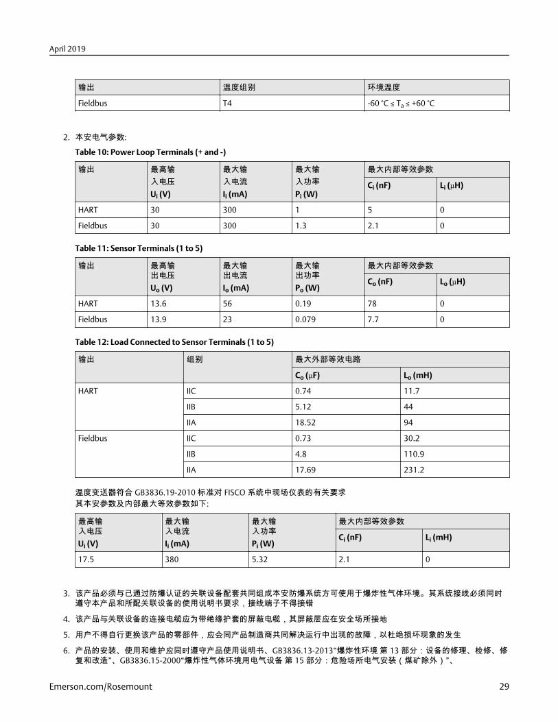
2. 本安电气参数:
Table 10: Power Loop Terminals (+ and -)
输出 最高输入电压Ui (V)
最大输入电流Ii (mA)
最大输入功率Pi (W)
最大内部等效参数
Ci (nF) Li (µH)
HART 30 300 1 5 0
Fieldbus 30 300 1.3 2.1 0
Table 11: Sensor Terminals (1 to 5)
输出 最高输出电压Uo (V)
最大输出电流Io (mA)
最大输出功率Po (W)
最大内部等效参数
Co (nF) Lo (µH)
HART 13.6 56 0.19 78 0
Fieldbus 13.9 23 0.079 7.7 0
Table 12: Load Connected to Sensor Terminals (1 to 5)
输出 组别 最大外部等效电路
Co (µF) Lo (mH)
HART IIC 0.74 11.7
IIB 5.12 44
IIA 18.52 94
Fieldbus IIC 0.73 30.2
IIB 4.8 110.9
IIA 17.69 231.2
温度变送器符合 GB3836.19-2010 标准对 FISCO 系统中现场仪表的有关要求其本安参数及内部最大等效参数如下:
最高输入电压Ui (V)
最大输入电流Ii (mA)
最大输入功率Pi (W)
最大内部等效参数
Ci (nF) Li (mH)
17.5 380 5.32 2.1 0
3. 该产品必须与已通过防爆认证的关联设备配套共同组成本安防爆系统方可使用于爆炸性气体环境。其系统接线必须同时遵守本产品和所配关联设备的使用说明书要求,接线端子不得接错
4. 该产品与关联设备的连接电缆应为带绝缘护套的屏蔽电缆,其屏蔽层应在安全场所接地
5. 用户不得自行更换该产品的零部件,应会同产品制造商共同解决运行中出现的故障,以杜绝损坏现象的发生
6. 产品的安装、使用和维护应同时遵守产品使用说明书、GB3836.13-2013“爆炸性环境 第 13 部分:设备的修理、检修、修复和改造”、GB3836.15-2000“爆炸性气体环境用电气设备 第 15 部分:危险场所电气安装(煤矿除外)”、
April 2019
Emerson.com/Rosemount 29
GB3836.16-2006“爆炸性气体环境用电气设备 第 16 部分:电气装置的检查和维护(煤矿除外)”、GB3836.18-2010“爆炸性环境 第 18 部分:本质安全系统”和 GB50257-2014“电气装置安装工程爆炸和火灾危险环境电力装置施工及验收规范”的有关规定
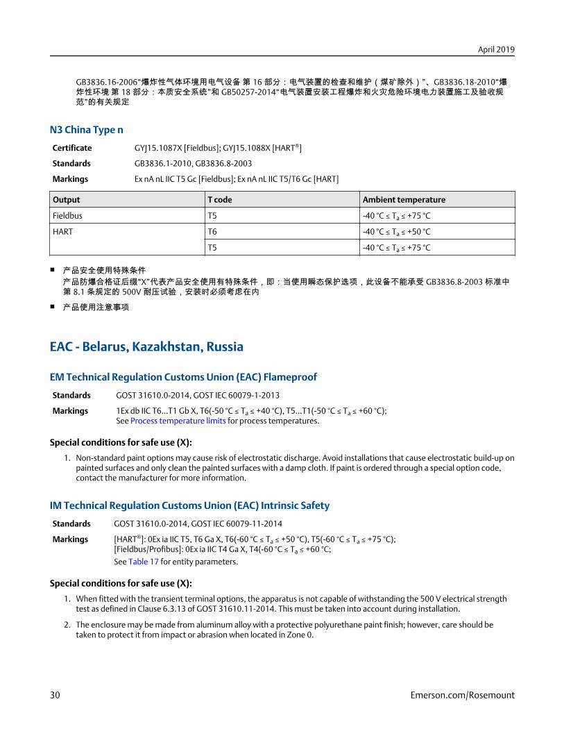
N3 China Type n
Certificate GYJ15.1087X [Fieldbus]; GYJ15.1088X [HART®]
Standards GB3836.1-2010, GB3836.8-2003
Markings Ex nA nL IIC T5 Gc [Fieldbus]; Ex nA nL IIC T5/T6 Gc [HART]
Output T code Ambient temperature
Fieldbus T5 -40 °C ≤ Ta ≤ +75 °C
HART T6 -40 °C ≤ Ta ≤ +50 °C
T5 -40 °C ≤ Ta ≤ +75 °C
■ 产品安全使用特殊条件产品防爆合格证后缀“X”代表产品安全使用有特殊条件,即:当使用瞬态保护选项,此设备不能承受 GB3836.8-2003 标准中第 8.1 条规定的 500V 耐压试验,安装时必须考虑在内
■ 产品使用注意事项
EAC - Belarus, Kazakhstan, Russia
EM Technical Regulation Customs Union (EAC) Flameproof
Standards GOST 31610.0-2014, GOST IEC 60079-1-2013
Markings 1Ex db IIC T6…T1 Gb X, T6(-50 °C ≤ Ta ≤ +40 °C), T5…T1(-50 °C ≤ Ta ≤ +60 °C);See Process temperature limits for process temperatures.
Special conditions for safe use (X):
1. Non-standard paint options may cause risk of electrostatic discharge. Avoid installations that cause electrostatic build-up onpainted surfaces and only clean the painted surfaces with a damp cloth. If paint is ordered through a special option code,contact the manufacturer for more information.
IM Technical Regulation Customs Union (EAC) Intrinsic Safety
Standards GOST 31610.0-2014, GOST IEC 60079-11-2014
Markings [HART®]: 0Ex ia IIC T5, T6 Ga X, T6(-60 °C ≤ Ta ≤ +50 °C), T5(-60 °C ≤ Ta ≤ +75 °C);[Fieldbus/Profibus]: 0Ex ia IIC T4 Ga X, T4(-60 °C ≤ Ta ≤ +60 °C;
See Table 17 for entity parameters.
Special conditions for safe use (X):
1. When fitted with the transient terminal options, the apparatus is not capable of withstanding the 500 V electrical strengthtest as defined in Clause 6.3.13 of GOST 31610.11-2014. This must be taken into account during installation.
2. The enclosure may be made from aluminum alloy with a protective polyurethane paint finish; however, care should betaken to protect it from impact or abrasion when located in Zone 0.
April 2019
30 Emerson.com/Rosemount
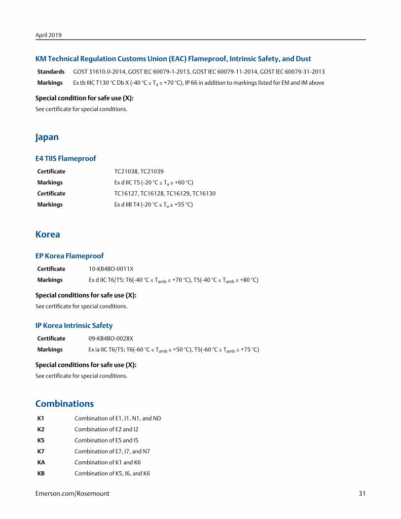
KM Technical Regulation Customs Union (EAC) Flameproof, Intrinsic Safety, and Dust
Standards GOST 31610.0-2014, GOST IEC 60079-1-2013, GOST IEC 60079-11-2014, GOST IEC 60079-31-2013
Markings Ex tb IIIC T130 °C Db X (-40 °C ≤ Ta ≤ +70 °C), IP 66 in addition to markings listed for EM and IM above
Special condition for safe use (X):
See certificate for special conditions.
Japan
E4 TIIS Flameproof
Certificate TC21038, TC21039
Markings Ex d IIC T5 (-20 °C ≤ Ta ≤ +60 °C)
Certificate TC16127, TC16128, TC16129, TC16130
Markings Ex d IIB T4 (-20 °C ≤ Ta ≤ +55 °C)
Korea
EP Korea Flameproof
Certificate 10-KB4BO-0011X
Markings Ex d IIC T6/T5; T6(-40 °C ≤ Tamb ≤ +70 °C), T5(-40 °C ≤ Tamb ≤ +80 °C)
Special conditions for safe use (X):
See certificate for special conditions.
IP Korea Intrinsic Safety
Certificate 09-KB4BO-0028X
Markings Ex ia IIC T6/T5; T6(-60 °C ≤ Tamb ≤ +50 °C), T5(-60 °C ≤ Tamb ≤ +75 °C)
Special conditions for safe use (X):
See certificate for special conditions.
Combinations
K1 Combination of E1, I1, N1, and ND
K2 Combination of E2 and I2
K5 Combination of E5 and I5
K7 Combination of E7, I7, and N7
KA Combination of K1 and K6
KB Combination of K5, I6, and K6
April 2019
Emerson.com/Rosemount 31
Tables
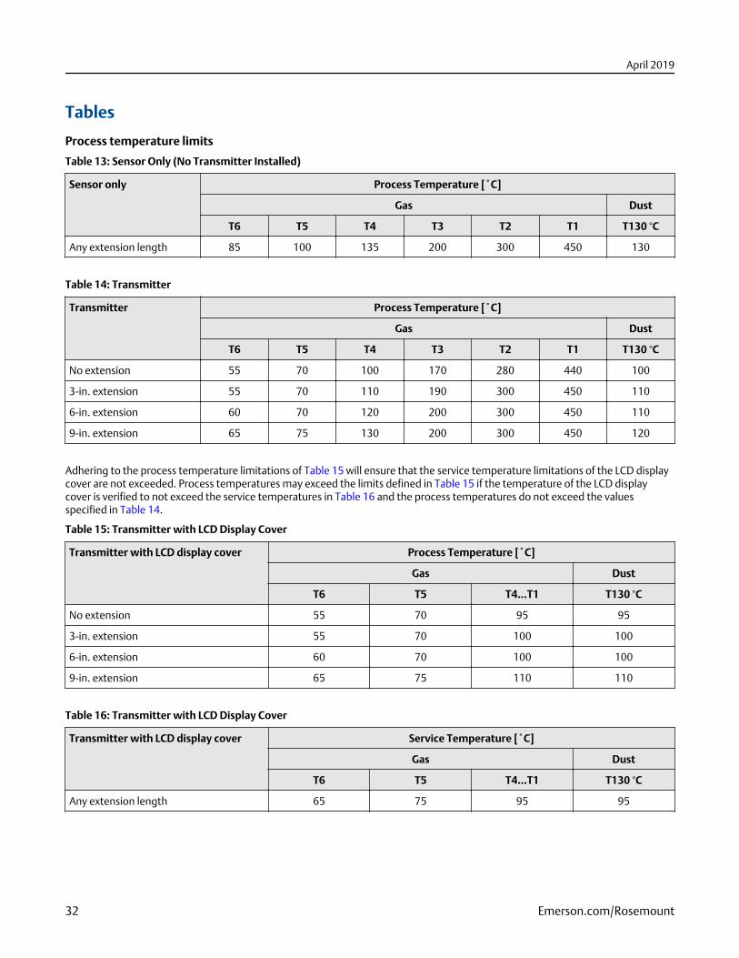
Process temperature limits
Table 13: Sensor Only (No Transmitter Installed)
Sensor only Process Temperature [˚C]
Gas Dust
T6 T5 T4 T3 T2 T1 T130 °C
Any extension length 85 100 135 200 300 450 130
Table 14: Transmitter
Transmitter Process Temperature [˚C]
Gas Dust
T6 T5 T4 T3 T2 T1 T130 °C
No extension 55 70 100 170 280 440 100
3-in. extension 55 70 110 190 300 450 110
6-in. extension 60 70 120 200 300 450 110
9-in. extension 65 75 130 200 300 450 120
Adhering to the process temperature limitations of Table 15 will ensure that the service temperature limitations of the LCD displaycover are not exceeded. Process temperatures may exceed the limits defined in Table 15 if the temperature of the LCD displaycover is verified to not exceed the service temperatures in Table 16 and the process temperatures do not exceed the valuesspecified in Table 14.
Table 15: Transmitter with LCD Display Cover
Transmitter with LCD display cover Process Temperature [˚C]
Gas Dust
T6 T5 T4...T1 T130 °C
No extension 55 70 95 95
3-in. extension 55 70 100 100
6-in. extension 60 70 100 100
9-in. extension 65 75 110 110
Table 16: Transmitter with LCD Display Cover
Transmitter with LCD display cover Service Temperature [˚C]
Gas Dust
T6 T5 T4...T1 T130 °C
Any extension length 65 75 95 95
April 2019
32 Emerson.com/Rosemount
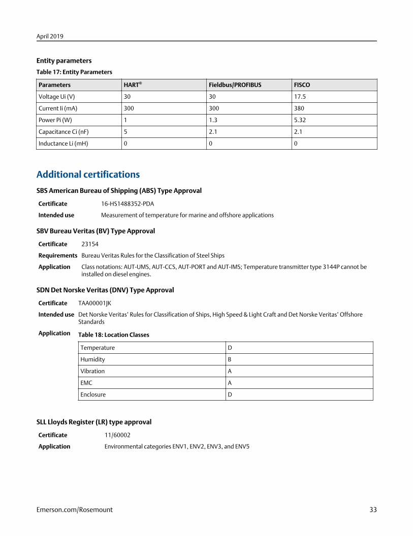
Entity parameters
Table 17: Entity Parameters
Parameters HART® Fieldbus/PROFIBUS FISCO
Voltage Ui (V) 30 30 17.5
Current Ii (mA) 300 300 380
Power Pi (W) 1 1.3 5.32
Capacitance Ci (nF) 5 2.1 2.1
Inductance Li (mH) 0 0 0
Additional certifications
SBS American Bureau of Shipping (ABS) Type Approval
Certificate 16-HS1488352-PDA
Intended use Measurement of temperature for marine and offshore applications
SBV Bureau Veritas (BV) Type Approval
Certificate 23154
Requirements Bureau Veritas Rules for the Classification of Steel Ships
Application Class notations: AUT-UMS, AUT-CCS, AUT-PORT and AUT-IMS; Temperature transmitter type 3144P cannot beinstalled on diesel engines.
SDN Det Norske Veritas (DNV) Type Approval
Certificate TAA00001JK
Intended use Det Norske Veritas’ Rules for Classification of Ships, High Speed & Light Craft and Det Norske Veritas’ OffshoreStandards
Application Table 18: Location Classes
Temperature D
Humidity B
Vibration A
EMC A
Enclosure D
SLL Lloyds Register (LR) type approval
Certificate 11/60002
Application Environmental categories ENV1, ENV2, ENV3, and ENV5
April 2019
Emerson.com/Rosemount 33
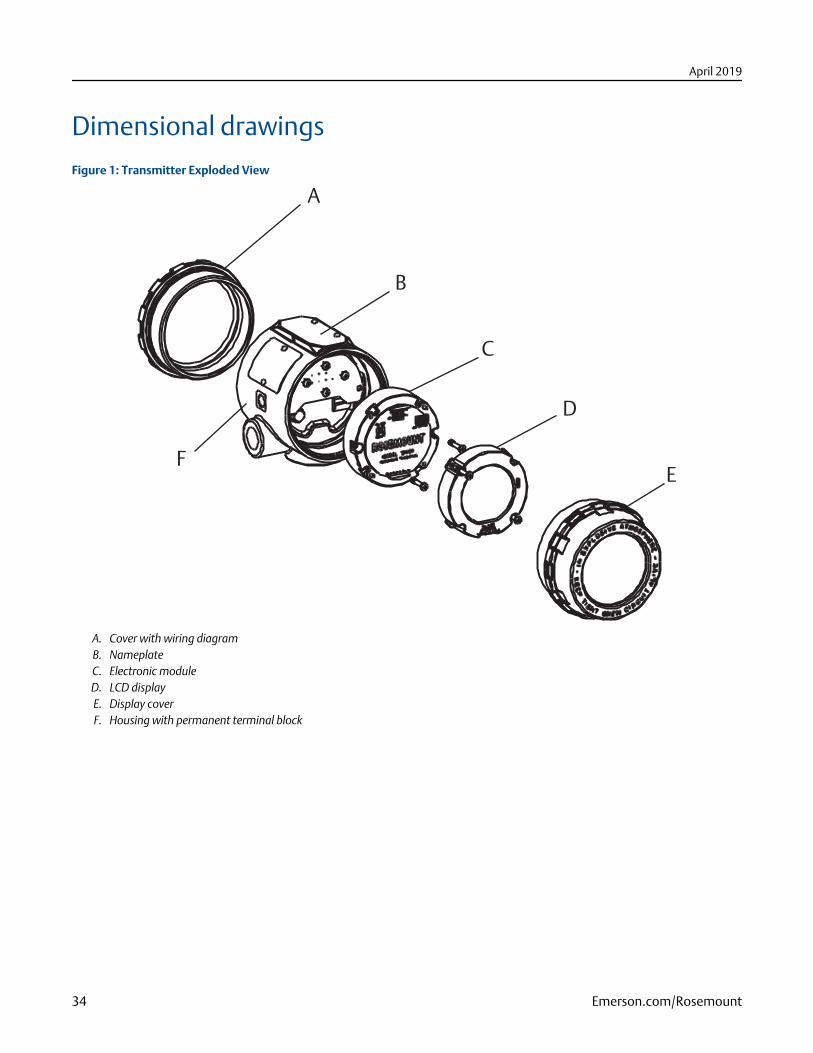
Dimensional drawingsFigure 1: Transmitter Exploded View
A
B
C
D
EF
A. Cover with wiring diagramB. NameplateC. Electronic moduleD. LCD displayE. Display coverF. Housing with permanent terminal block
April 2019
34 Emerson.com/Rosemount
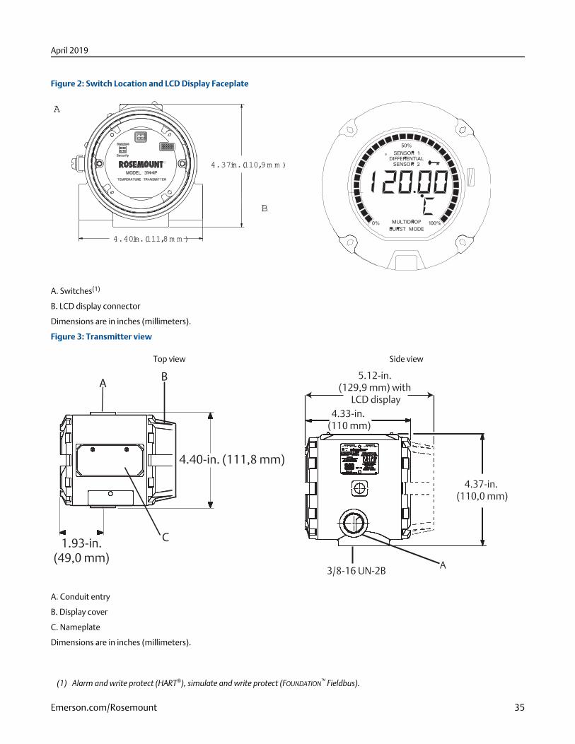
Figure 2: Switch Location and LCD Display Faceplate
4.37-in. (110,9 m m )
4.40-in. (111,8 m m )
A
B
A. Switches(1)
B. LCD display connector
Dimensions are in inches (millimeters).
Figure 3: Transmitter view
Top view Side view
1.93-in.(49,0 mm)
4.40-in. (111,8 mm)
AB
C
3/8-16 UN-2B
4.37-in. (110,0 mm)
4.33-in. (110 mm)
5.12-in. (129,9 mm) with
LCD display
A
A. Conduit entry
B. Display cover
C. Nameplate
Dimensions are in inches (millimeters).
(1) Alarm and write protect (HART®), simulate and write protect (FOUNDATION™ Fieldbus).
April 2019
Emerson.com/Rosemount 35
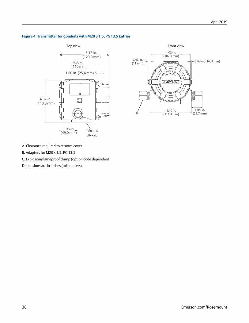
Figure 4: Transmitter for Conduits with M20 3 1.5, PG 13.5 Entries
Top view Front view
5.12-in. (129,9 mm)
4.33-in. (110 mm)
1.00-in. (25,4 mm) A
4.37-in.(110,0 mm)
1.93-in.(49,0 mm) 3/8–16
UN–2B
4.02-in. (102,1 mm)
0.64-in. (16, 3 mm)C
0.43-in.(11 mm)
4.40 in.(111,8 mm)
1.05-in.(26,7 mm)B
A. Clearance required to remove cover
B. Adapters for M20 x 1.5, PG 13.5
C. Explosion/flameproof clamp (option code dependent)
Dimensions are in inches (millimeters).
April 2019
36 Emerson.com/Rosemount
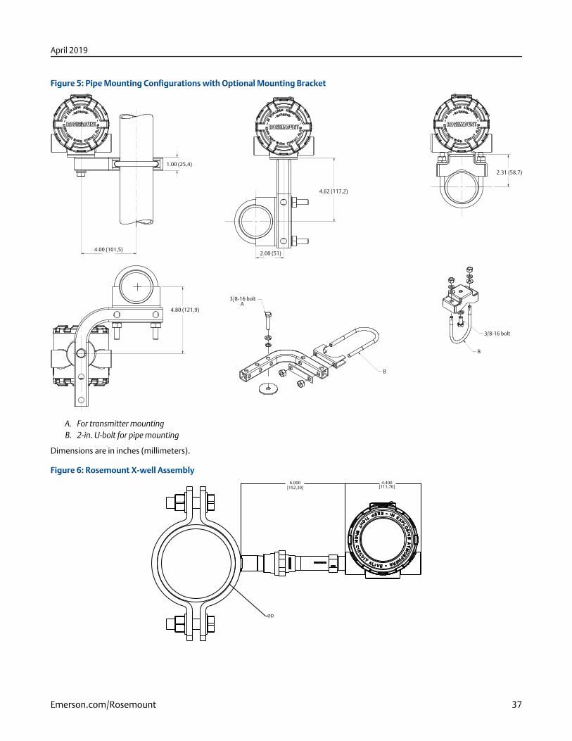
Figure 5: Pipe Mounting Configurations with Optional Mounting Bracket
3/8-16 bolt
1.00 (25,4)
4.00 (101,5)
4.62 (117,2)
2.00 (51)
2.31 (58,7)
3/8-16 bolt
B
B
A4.80 (121,9)
A. For transmitter mountingB. 2-in. U-bolt for pipe mounting
Dimensions are in inches (millimeters).
Figure 6: Rosemount X-well Assembly4.400[111,76]
6.000
[152,39]
ØD
April 2019
Emerson.com/Rosemount 37
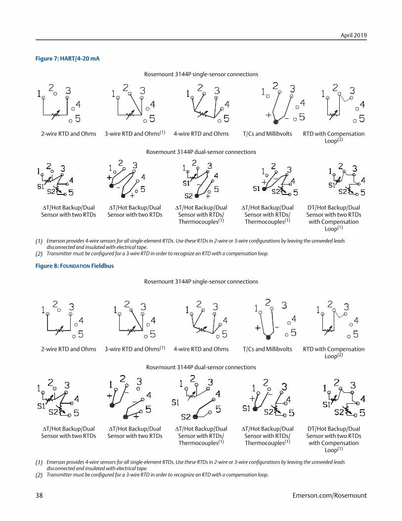
Figure 7: HART/4-20 mA
Rosemount 3144P single-sensor connections
2-wire RTD and Ohms 3-wire RTD and Ohms(1) 4-wire RTD and Ohms T/Cs and Millibvolts RTD with CompensationLoop(2)
Rosemount 3144P dual-sensor connections
ΔT/Hot Backup/DualSensor with two RTDs
ΔT/Hot Backup/DualSensor with two RTDs
ΔT/Hot Backup/DualSensor with RTDs/Thermocouples(1)
ΔT/Hot Backup/DualSensor with RTDs/Thermocouples(1)
DT/Hot Backup/DualSensor with two RTDs
with CompensationLoop(1)
(1) Emerson provides 4-wire sensors for all single-element RTDs. Use these RTDs in 2-wire or 3-wire configurations by leaving the unneeded leadsdisconnected and insulated with electrical tape.
(2) Transmitter must be configured for a 3-wire RTD in order to recognize an RTD with a compensation loop.
Figure 8: FOUNDATION Fieldbus
Rosemount 3144P single-sensor connections
2-wire RTD and Ohms 3-wire RTD and Ohms(1) 4-wire RTD and Ohms T/Cs and Millibvolts RTD with CompensationLoop(2)
Rosemount 3144P dual-sensor connections
ΔT/Hot Backup/DualSensor with two RTDs
ΔT/Hot Backup/DualSensor with two RTDs
ΔT/Hot Backup/DualSensor with RTDs/Thermocouples(1)
ΔT/Hot Backup/DualSensor with RTDs/Thermocouples(1)
DT/Hot Backup/DualSensor with two RTDs
with CompensationLoop(1)
(1) Emerson provides 4-wire sensors for all single-element RTDs. Use these RTDs in 2-wire or 3-wire configurations by leaving the unneeded leadsdisconnected and insulated with electrical tape.
(2) Transmitter must be configured for a 3-wire RTD in order to recognize an RTD with a compensation loop.
April 2019
38 Emerson.com/Rosemount
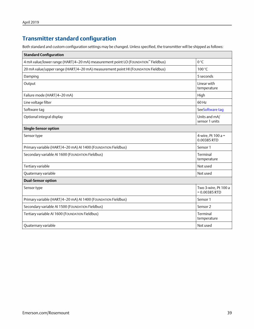
Transmitter standard configurationBoth standard and custom configuration settings may be changed. Unless specified, the transmitter will be shipped as follows:
Standard Configuration
4 mA value/lower range (HART/4–20 mA) measurement point LO (FOUNDATION™ Fieldbus) 0 °C
20 mA value/upper range (HART/4–20 mA) measurement point HI (FOUNDATION Fieldbus) 100 °C
Damping 5 seconds
Output Linear withtemperature
Failure mode (HART/4–20 mA) High
Line voltage filter 60 Hz
Software tag SeeSoftware tag
Optional integral display Units and mA/sensor 1 units
Single-Sensor option
Sensor type 4-wire, Pt 100 a =0.00385 RTD
Primary variable (HART/4–20 mA) AI 1400 (FOUNDATION Fieldbus) Sensor 1
Secondary variable AI 1600 (FOUNDATION Fieldbus) Terminaltemperature
Tertiary variable Not used
Quaternary variable Not used
Dual-Sensor option
Sensor type Two 3-wire, Pt 100 a= 0.00385 RTD
Primary variable (HART/4–20 mA) AI 1400 (FOUNDATION Fieldbus) Sensor 1
Secondary variable AI 1500 (FOUNDATION Fieldbus) Sensor 2
Tertiary variable AI 1600 (FOUNDATION Fieldbus) Terminaltemperature
Quaternary variable Not used
April 2019
Emerson.com/Rosemount 39
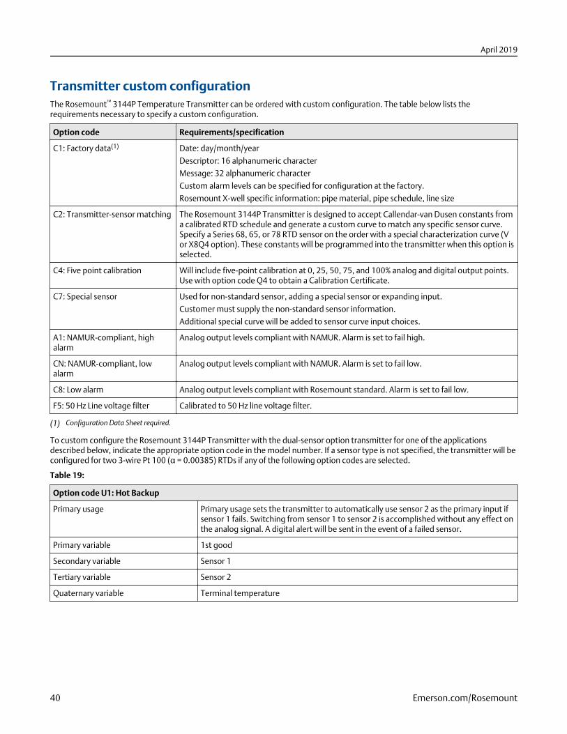
Transmitter custom configurationThe Rosemount™ 3144P Temperature Transmitter can be ordered with custom configuration. The table below lists therequirements necessary to specify a custom configuration.
Option code Requirements/specification
C1: Factory data(1) Date: day/month/year
Descriptor: 16 alphanumeric character
Message: 32 alphanumeric character
Custom alarm levels can be specified for configuration at the factory.
Rosemount X-well specific information: pipe material, pipe schedule, line size
C2: Transmitter-sensor matching The Rosemount 3144P Transmitter is designed to accept Callendar-van Dusen constants froma calibrated RTD schedule and generate a custom curve to match any specific sensor curve.Specify a Series 68, 65, or 78 RTD sensor on the order with a special characterization curve (Vor X8Q4 option). These constants will be programmed into the transmitter when this option isselected.
C4: Five point calibration Will include five-point calibration at 0, 25, 50, 75, and 100% analog and digital output points.Use with option code Q4 to obtain a Calibration Certificate.
C7: Special sensor Used for non-standard sensor, adding a special sensor or expanding input.
Customer must supply the non-standard sensor information.
Additional special curve will be added to sensor curve input choices.
A1: NAMUR-compliant, highalarm
Analog output levels compliant with NAMUR. Alarm is set to fail high.
CN: NAMUR-compliant, lowalarm
Analog output levels compliant with NAMUR. Alarm is set to fail low.
C8: Low alarm Analog output levels compliant with Rosemount standard. Alarm is set to fail low.
F5: 50 Hz Line voltage filter Calibrated to 50 Hz line voltage filter.
(1) Configuration Data Sheet required.
To custom configure the Rosemount 3144P Transmitter with the dual-sensor option transmitter for one of the applicationsdescribed below, indicate the appropriate option code in the model number. If a sensor type is not specified, the transmitter will beconfigured for two 3-wire Pt 100 (α = 0.00385) RTDs if any of the following option codes are selected.
Table 19:
Option code U1: Hot Backup
Primary usage Primary usage sets the transmitter to automatically use sensor 2 as the primary input ifsensor 1 fails. Switching from sensor 1 to sensor 2 is accomplished without any effect onthe analog signal. A digital alert will be sent in the event of a failed sensor.
Primary variable 1st good
Secondary variable Sensor 1
Tertiary variable Sensor 2
Quaternary variable Terminal temperature
April 2019
40 Emerson.com/Rosemount
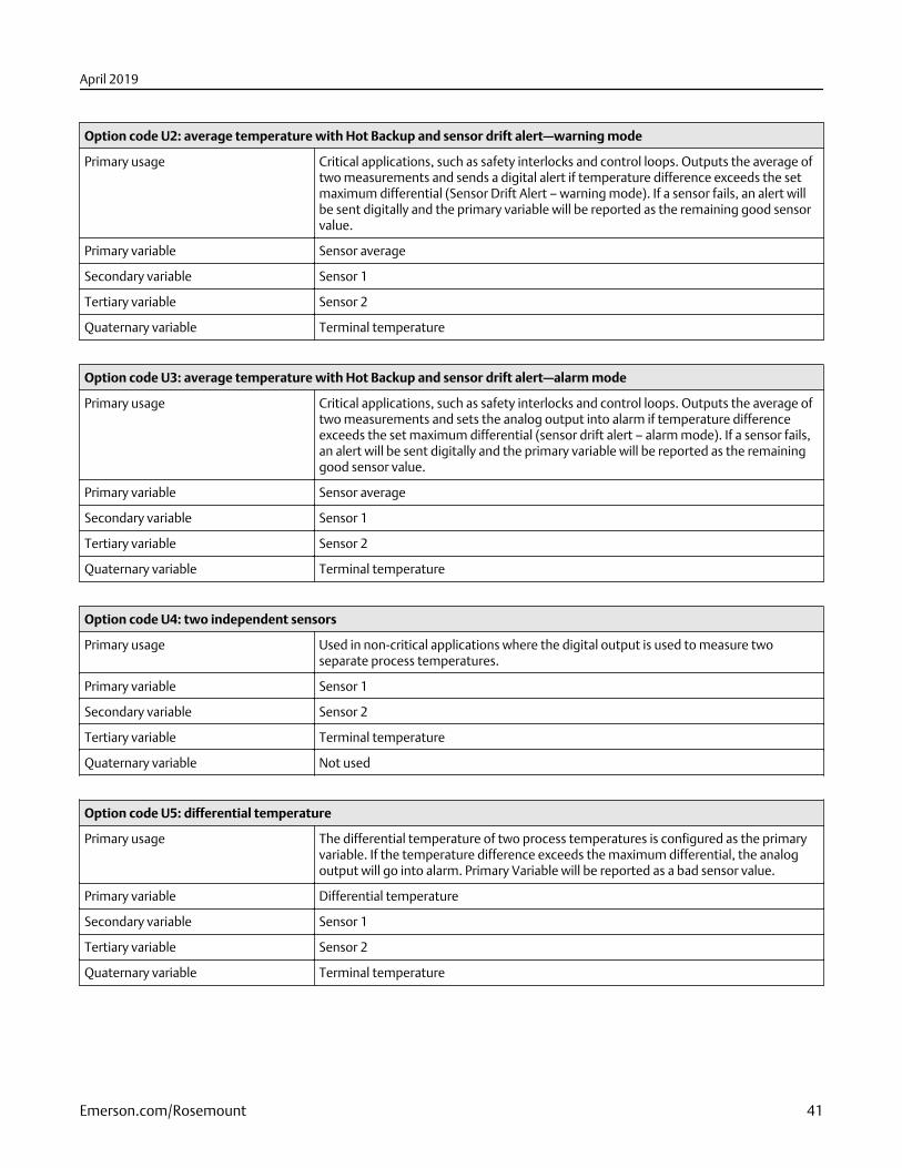
Option code U2: average temperature with Hot Backup and sensor drift alert—warning mode
Primary usage Critical applications, such as safety interlocks and control loops. Outputs the average oftwo measurements and sends a digital alert if temperature difference exceeds the setmaximum differential (Sensor Drift Alert – warning mode). If a sensor fails, an alert willbe sent digitally and the primary variable will be reported as the remaining good sensorvalue.
Primary variable Sensor average
Secondary variable Sensor 1
Tertiary variable Sensor 2
Quaternary variable Terminal temperature
Option code U3: average temperature with Hot Backup and sensor drift alert—alarm mode
Primary usage Critical applications, such as safety interlocks and control loops. Outputs the average oftwo measurements and sets the analog output into alarm if temperature differenceexceeds the set maximum differential (sensor drift alert – alarm mode). If a sensor fails,an alert will be sent digitally and the primary variable will be reported as the remaininggood sensor value.
Primary variable Sensor average
Secondary variable Sensor 1
Tertiary variable Sensor 2
Quaternary variable Terminal temperature
Option code U4: two independent sensors
Primary usage Used in non-critical applications where the digital output is used to measure twoseparate process temperatures.
Primary variable Sensor 1
Secondary variable Sensor 2
Tertiary variable Terminal temperature
Quaternary variable Not used
Option code U5: differential temperature
Primary usage The differential temperature of two process temperatures is configured as the primaryvariable. If the temperature difference exceeds the maximum differential, the analogoutput will go into alarm. Primary Variable will be reported as a bad sensor value.
Primary variable Differential temperature
Secondary variable Sensor 1
Tertiary variable Sensor 2
Quaternary variable Terminal temperature
April 2019
Emerson.com/Rosemount 41
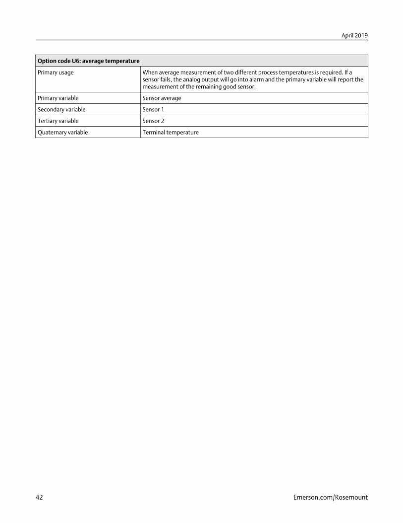
Option code U6: average temperature
Primary usage When average measurement of two different process temperatures is required. If asensor fails, the analog output will go into alarm and the primary variable will report themeasurement of the remaining good sensor.
Primary variable Sensor average
Secondary variable Sensor 1
Tertiary variable Sensor 2
Quaternary variable Terminal temperature
April 2019
42 Emerson.com/Rosemount

April 2019
Emerson.com/Rosemount 43

00813-0100-4021Rev. SB
April 2019
Global HeadquartersEmerson Automation Solutions6021 Innovation Blvd.Shakopee, MN 55379, USA
+1 800 999 9307 or +1 952 906 8888
+1 952 949 7001
North America Regional OfficeEmerson Automation Solutions8200 Market Blvd.Chanhassen, MN 55317, USA
+1 800 999 9307 or +1 952 906 8888
+1 952 949 7001
Latin America Regional OfficeEmerson Automation Solutions1300 Concord Terrace, Suite 400Sunrise, FL 33323, USA
+1 954 846 5030
+1 954 846 5121
Europe Regional OfficeEmerson Automation Solutions EuropeGmbHNeuhofstrasse 19a P.O. Box 1046CH 6340 BaarSwitzerland
+41 (0) 41 768 6111
+41 (0) 41 768 6300
Asia Pacific Regional OfficeEmerson Automation Solutions1 Pandan CrescentSingapore 128461
+65 6777 8211
+65 6777 0947
Middle East and Africa Regional OfficeEmerson Automation SolutionsEmerson FZE P.O. Box 17033Jebel Ali Free Zone - South 2Dubai, United Arab Emirates
+971 4 8118100
+971 4 8865465
Linkedin.com/company/Emerson-Automation-Solutions
Twitter.com/Rosemount_News
Facebook.com/Rosemount
Youtube.com/user/RosemountMeasurement
©2019 Emerson. All rights reserved.
Emerson Terms and Conditions of Sale are available upon request. The Emerson logo is atrademark and service mark of Emerson Electric Co. Rosemount is mark of one of theEmerson family of companies. All other marks are the property of their respective owners.