Embed Size (px)
Citation preview
Product Data Sheet00813-0100-4001, Rev LANovember 2010 Rosemount 3051
Rosemount 3051 Pressure Transmitter
THE PROVEN INDUSTRY LEADER IN PRESSURE MEASUREMENT• Best-in-Class performance with up to 0.04% reference accuracy
• Industry first installed five-year stability
• Unmatched Dynamic Performance
• Coplanar™ platform enables integrated pressure, flow, and level solutions
• Advanced PlantWeb® Functionality to increase plant productivity
www.rosemount.com
ContentsSetting the Standard for Pressure Measurement. . . . . . . . . . . . . . . . . . . . . . . . . . . .page 2
Ordering Information
Rosemount 3051C Coplanar Pressure Transmitter . . . . . . . . . . . . . . . . . . . . .page 3
Rosemount 3051T In-Line Pressure Transmitter . . . . . . . . . . . . . . . . . . . . . .page 10
Rosemount 3051CF Flowmeter Series . . . . . . . . . . . . . . . . . . . . . . . . . . . . .page 14
Rosemount 3051L Liquid Level Transmitter . . . . . . . . . . . . . . . . . . . . . . . . .page 29
Specifications. . . . . . . . . . . . . . . . . . . . . . . . . . . . . . . . . . . . . . . . . . . . . . . . . . . . . .page 35
Product Certifications. . . . . . . . . . . . . . . . . . . . . . . . . . . . . . . . . . . . . . . . . . . . . . . .page 44
Dimensional Drawings. . . . . . . . . . . . . . . . . . . . . . . . . . . . . . . . . . . . . . . . . . . . . . .page 49
Product Data Sheet00813-0100-4001, Rev LA
November 2010Rosemount 3051
2
Setting the Standard for Pressure Measurement
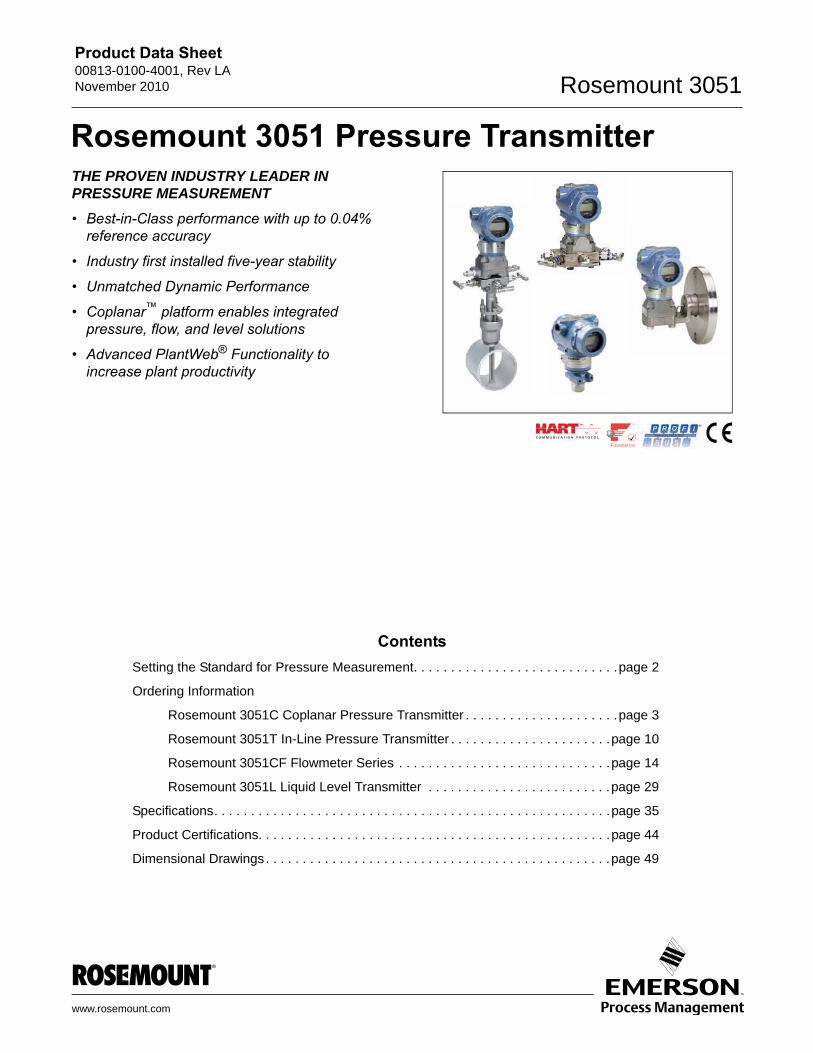
Proven best-in-class performance, reliability and safety• Over 4 million installed
• Meet your application needs with extensive offering
• Real world total performance of ±0.15%
• Reference accuracy of ±0.04%
Maximize Installation Flexibility with Coplanar Platform• Improve reliability and performance with integrated DP Flowmeters, DP Level
and manifolds
• Easy installation with all solutions fully assembled, leak-tested and calibrated
• Meet your application needs with an unsurpassed offering
Unlock the Value of Devices with the Smart Wireless THUM™ Adapter• Gain access to field intelligence and improve quality, safety, availability,
operations and maintenance costs
• Remotely manage devices and monitor health
• Enable new wireless measurement points
• Utilize existing loop power
Innovative, Integrated DP Flowmeters• Fully assembled and leak tested for out-of-the-box installation
• Reduce straight pipe requirements, lower permanent pressure loss and achieve accurate measurement in small line sizes
• Up to 1.65% volumetric flow accuracy at 8:1 turndown
Proven, Reliable and Innovative DP Level Technologies• Connect to virtually any process with a comprehensive offering of process
connections, fill fluids, direct mount or capillary connections and materials
• Quantify and optimize total system performance with QZ option
• Operate at higher temperature and in vacuum applications
• Optimize level measurement with cost efficient Tuned-System™ Assemblies
Instrument Manifolds – Quality, Convenient, and Easy• Design and engineered for optimal performance with Rosemount transmitters
• Save installation time and money with factory assembly
• Offers a variety of styles, materials and configurations
Flow
Pressure
Level
Product Data Sheet00813-0100-4001, Rev LANovember 2010 Rosemount 3051
3
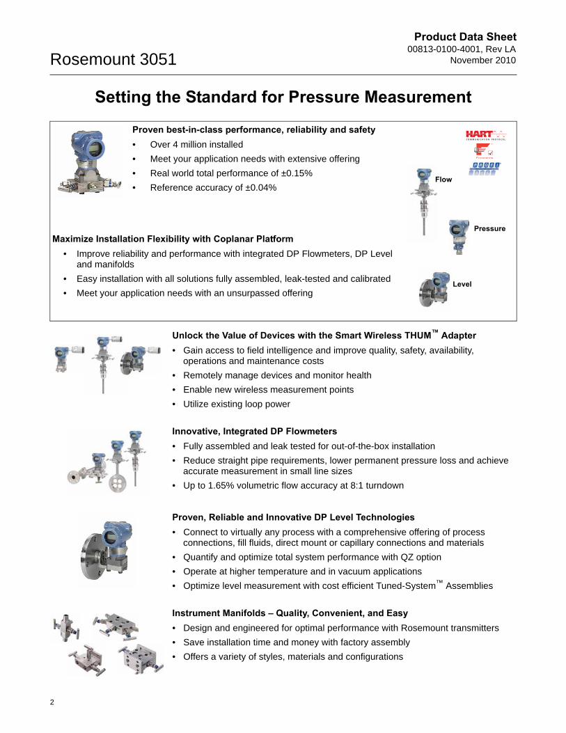
Rosemount 3051C Coplanar Pressure Transmitter
Industry’s best total performance, a flexible Coplanar platform, and installed five-year stability has made Rosemount 3051 the standard for Differential, Gage, and Absolute pressure measurement. Select from the following capabilities for seamless integration:
• Performance up to 0.04% accuracy
• Manifolds, Primary Elements and Seal Solutions
• 4-20 mA HART, 1-5 Vdc HART low power, FOUNDATION fieldbus, and Profibus PA protocols
• Calibrated spans/ranges from 0.1 inH2O to 4000 psi (0,25 mbar to 276 bar)
• 316 SST, Alloy C-276, Alloy 400, Tantalum, Gold-Plated Alloy 400 or 316L SST wetted materials
Additional InformationSpecifications: page 35Certifications: page 44Dimensional Drawings: page 49
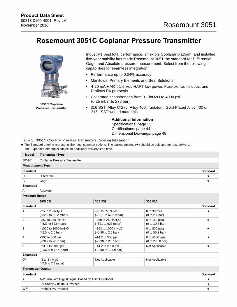
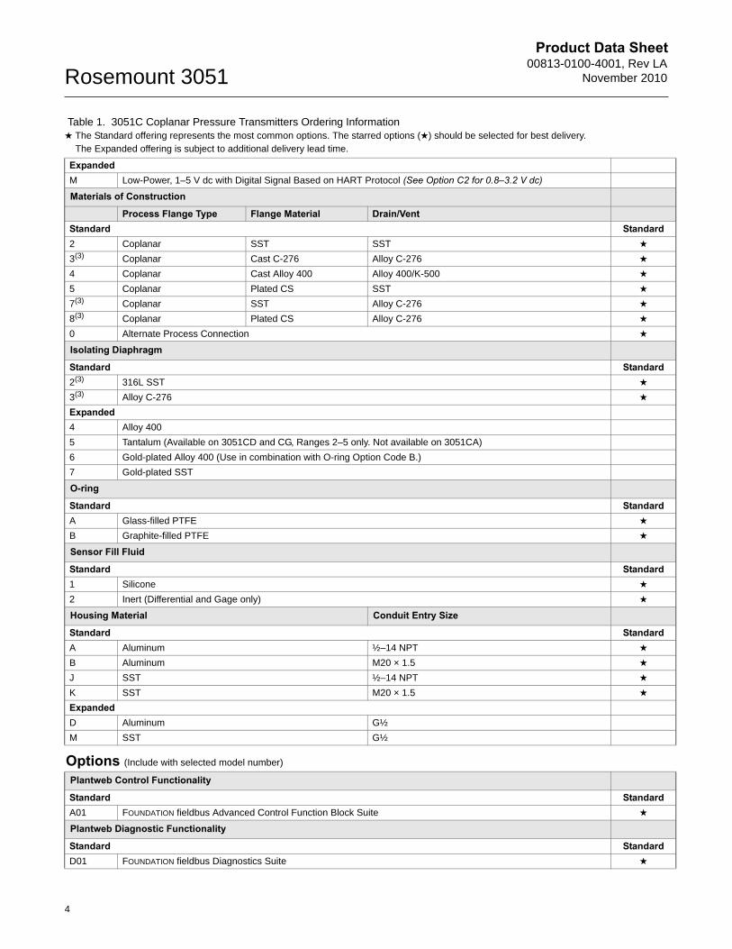
Table 1. 3051C Coplanar Pressure Transmitters Ordering Information★ The Standard offering represents the most common options. The starred options (★) should be selected for best delivery.__The Expanded offering is subject to additional delivery lead time.
Model Transmitter Type
3051C Coplanar Pressure Transmitter
Measurement Type
Standard StandardD Differential ★
G Gage ★
ExpandedA Absolute
Pressure Range
3051CD 3051CG 3051CAStandard Standard1 –25 to 25 inH2O
(–62.2 to 62.2 mbar)–25 to 25 inH2O(–62,1 to 62.2 mbar)
0 to 30 psia(0 to 2.1 bar)
★
2 –250 to 250 inH2O(–623 to 623 mbar)
–250 to 250 inH2O(–621 to 623 mbar)
0 to 150 psia(0 to 10.3 bar)
★
3 –1000 to 1000 inH2O(–2.5 to 2.5 bar)
–393 to 1000 inH2O(–0.98 to 2.5 bar)
0 to 800 psia(0 to 55.2 bar)
★
4 –300 to 300 psi(–20.7 to 20.7 bar)
–14.2 to 300 psi(–0.98 to 20.7 bar)
0 to 4000 psia(0 to 275.8 bar)
★
5 –2000 to 2000 psi(–137.9 to137.9 bar)
–14.2 to 2000 psi(–0.98 to 137.9 bar)
Not Applicable ★
Expanded0(1) –3 to 3 inH2O
(–7.5 to 7.5 mbar)Not Applicable Not Applicable
Transmitter Output
Standard StandardA 4–20 mA with Digital Signal Based on HART Protocol ★
F FOUNDATION fieldbus Protocol ★
W(2) Profibus PA Protocol ★
3051C Coplanar Pressure Transmitter
Product Data Sheet00813-0100-4001, Rev LA
November 2010Rosemount 3051
ExpandedM Low-Power, 1–5 V dc with Digital Signal Based on HART Protocol (See Option C2 for 0.8–3.2 V dc)
Materials of Construction
Process Flange Type Flange Material Drain/VentStandard Standard2 Coplanar SST SST ★
3(3) Coplanar Cast C-276 Alloy C-276 ★
4 Coplanar Cast Alloy 400 Alloy 400/K-500 ★
5 Coplanar Plated CS SST ★
7(3) Coplanar SST Alloy C-276 ★
8(3) Coplanar Plated CS Alloy C-276 ★
0 Alternate Process Connection ★
Isolating Diaphragm
Standard Standard2(3) 316L SST ★
3(3) Alloy C-276 ★
Expanded4 Alloy 400
5 Tantalum (Available on 3051CD and CG, Ranges 2–5 only. Not available on 3051CA)
6 Gold-plated Alloy 400 (Use in combination with O-ring Option Code B.)
7 Gold-plated SST
O-ring
Standard StandardA Glass-filled PTFE ★
B Graphite-filled PTFE ★
Sensor Fill Fluid
Standard Standard1 Silicone ★
2 Inert (Differential and Gage only) ★
Housing Material Conduit Entry Size
Standard StandardA Aluminum ½–14 NPT ★
B Aluminum M20 × 1.5 ★
J SST ½–14 NPT ★
K SST M20 × 1.5 ★
ExpandedD Aluminum G½
M SST G½
Options (Include with selected model number)
Plantweb Control Functionality
Standard StandardA01 FOUNDATION fieldbus Advanced Control Function Block Suite ★
Plantweb Diagnostic Functionality
Standard StandardD01 FOUNDATION fieldbus Diagnostics Suite ★
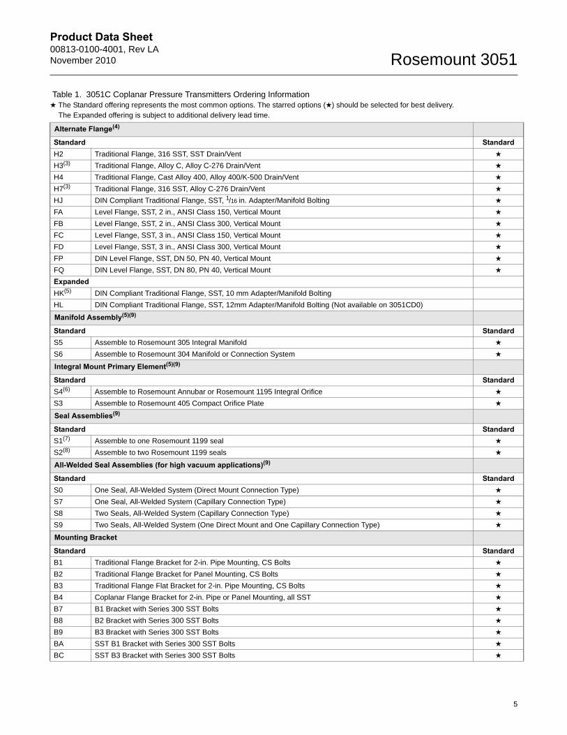
Table 1. 3051C Coplanar Pressure Transmitters Ordering Information★ The Standard offering represents the most common options. The starred options (★) should be selected for best delivery.__The Expanded offering is subject to additional delivery lead time.
4
Product Data Sheet00813-0100-4001, Rev LANovember 2010 Rosemount 3051
Alternate Flange(4)
Standard StandardH2 Traditional Flange, 316 SST, SST Drain/Vent ★
H3(3) Traditional Flange, Alloy C, Alloy C-276 Drain/Vent ★
H4 Traditional Flange, Cast Alloy 400, Alloy 400/K-500 Drain/Vent ★
H7(3) Traditional Flange, 316 SST, Alloy C-276 Drain/Vent ★
HJ DIN Compliant Traditional Flange, SST, 1/16 in. Adapter/Manifold Bolting ★
FA Level Flange, SST, 2 in., ANSI Class 150, Vertical Mount ★
FB Level Flange, SST, 2 in., ANSI Class 300, Vertical Mount ★
FC Level Flange, SST, 3 in., ANSI Class 150, Vertical Mount ★
FD Level Flange, SST, 3 in., ANSI Class 300, Vertical Mount ★
FP DIN Level Flange, SST, DN 50, PN 40, Vertical Mount ★
FQ DIN Level Flange, SST, DN 80, PN 40, Vertical Mount ★
ExpandedHK(5) DIN Compliant Traditional Flange, SST, 10 mm Adapter/Manifold Bolting
HL DIN Compliant Traditional Flange, SST, 12mm Adapter/Manifold Bolting (Not available on 3051CD0)
Manifold Assembly(5)(9)
Standard StandardS5 Assemble to Rosemount 305 Integral Manifold ★
S6 Assemble to Rosemount 304 Manifold or Connection System ★
Integral Mount Primary Element(5)(9)
Standard StandardS4(6) Assemble to Rosemount Annubar or Rosemount 1195 Integral Orifice ★
S3 Assemble to Rosemount 405 Compact Orifice Plate ★
Seal Assemblies(9)
Standard StandardS1(7) Assemble to one Rosemount 1199 seal ★
S2(8) Assemble to two Rosemount 1199 seals ★
All-Welded Seal Assemblies (for high vacuum applications)(9)
Standard StandardS0 One Seal, All-Welded System (Direct Mount Connection Type) ★
S7 One Seal, All-Welded System (Capillary Connection Type) ★
S8 Two Seals, All-Welded System (Capillary Connection Type) ★
S9 Two Seals, All-Welded System (One Direct Mount and One Capillary Connection Type) ★
Mounting Bracket
Standard StandardB1 Traditional Flange Bracket for 2-in. Pipe Mounting, CS Bolts ★
B2 Traditional Flange Bracket for Panel Mounting, CS Bolts ★
B3 Traditional Flange Flat Bracket for 2-in. Pipe Mounting, CS Bolts ★
B4 Coplanar Flange Bracket for 2-in. Pipe or Panel Mounting, all SST ★
B7 B1 Bracket with Series 300 SST Bolts ★
B8 B2 Bracket with Series 300 SST Bolts ★
B9 B3 Bracket with Series 300 SST Bolts ★
BA SST B1 Bracket with Series 300 SST Bolts ★
BC SST B3 Bracket with Series 300 SST Bolts ★
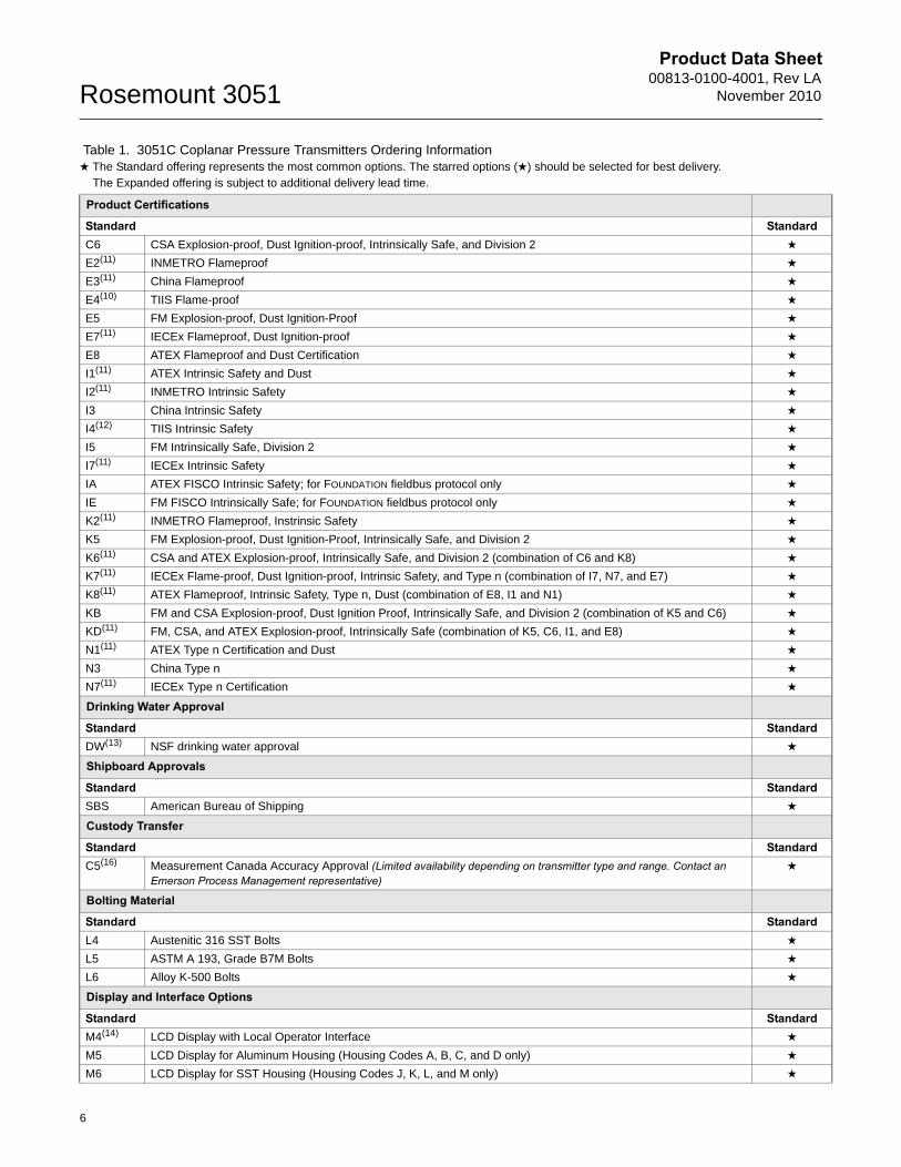
Table 1. 3051C Coplanar Pressure Transmitters Ordering Information★ The Standard offering represents the most common options. The starred options (★) should be selected for best delivery.__The Expanded offering is subject to additional delivery lead time.
5
Product Data Sheet00813-0100-4001, Rev LA
November 2010Rosemount 3051
Product Certifications
Standard StandardC6 CSA Explosion-proof, Dust Ignition-proof, Intrinsically Safe, and Division 2 ★
E2(11) INMETRO Flameproof ★
E3(11) China Flameproof ★
E4(10) TIIS Flame-proof ★
E5 FM Explosion-proof, Dust Ignition-Proof ★
E7(11) IECEx Flameproof, Dust Ignition-proof ★
E8 ATEX Flameproof and Dust Certification ★
I1(11) ATEX Intrinsic Safety and Dust ★
I2(11) INMETRO Intrinsic Safety ★
I3 China Intrinsic Safety ★
I4(12) TIIS Intrinsic Safety ★
I5 FM Intrinsically Safe, Division 2 ★
I7(11) IECEx Intrinsic Safety ★
IA ATEX FISCO Intrinsic Safety; for FOUNDATION fieldbus protocol only ★
IE FM FISCO Intrinsically Safe; for FOUNDATION fieldbus protocol only ★
K2(11) INMETRO Flameproof, Instrinsic Safety ★
K5 FM Explosion-proof, Dust Ignition-Proof, Intrinsically Safe, and Division 2 ★
K6(11) CSA and ATEX Explosion-proof, Intrinsically Safe, and Division 2 (combination of C6 and K8) ★
K7(11) IECEx Flame-proof, Dust Ignition-proof, Intrinsic Safety, and Type n (combination of I7, N7, and E7) ★
K8(11) ATEX Flameproof, Intrinsic Safety, Type n, Dust (combination of E8, I1 and N1) ★
KB FM and CSA Explosion-proof, Dust Ignition Proof, Intrinsically Safe, and Division 2 (combination of K5 and C6) ★
KD(11) FM, CSA, and ATEX Explosion-proof, Intrinsically Safe (combination of K5, C6, I1, and E8) ★
N1(11) ATEX Type n Certification and Dust ★
N3 China Type n ★
N7(11) IECEx Type n Certification ★
Drinking Water Approval
Standard StandardDW(13) NSF drinking water approval ★
Shipboard Approvals
Standard StandardSBS American Bureau of Shipping ★
Custody Transfer
Standard StandardC5(16) Measurement Canada Accuracy Approval (Limited availability depending on transmitter type and range. Contact an
Emerson Process Management representative)★
Bolting Material
Standard StandardL4 Austenitic 316 SST Bolts ★
L5 ASTM A 193, Grade B7M Bolts ★
L6 Alloy K-500 Bolts ★
Display and Interface Options
Standard StandardM4(14) LCD Display with Local Operator Interface ★
M5 LCD Display for Aluminum Housing (Housing Codes A, B, C, and D only) ★
M6 LCD Display for SST Housing (Housing Codes J, K, L, and M only) ★
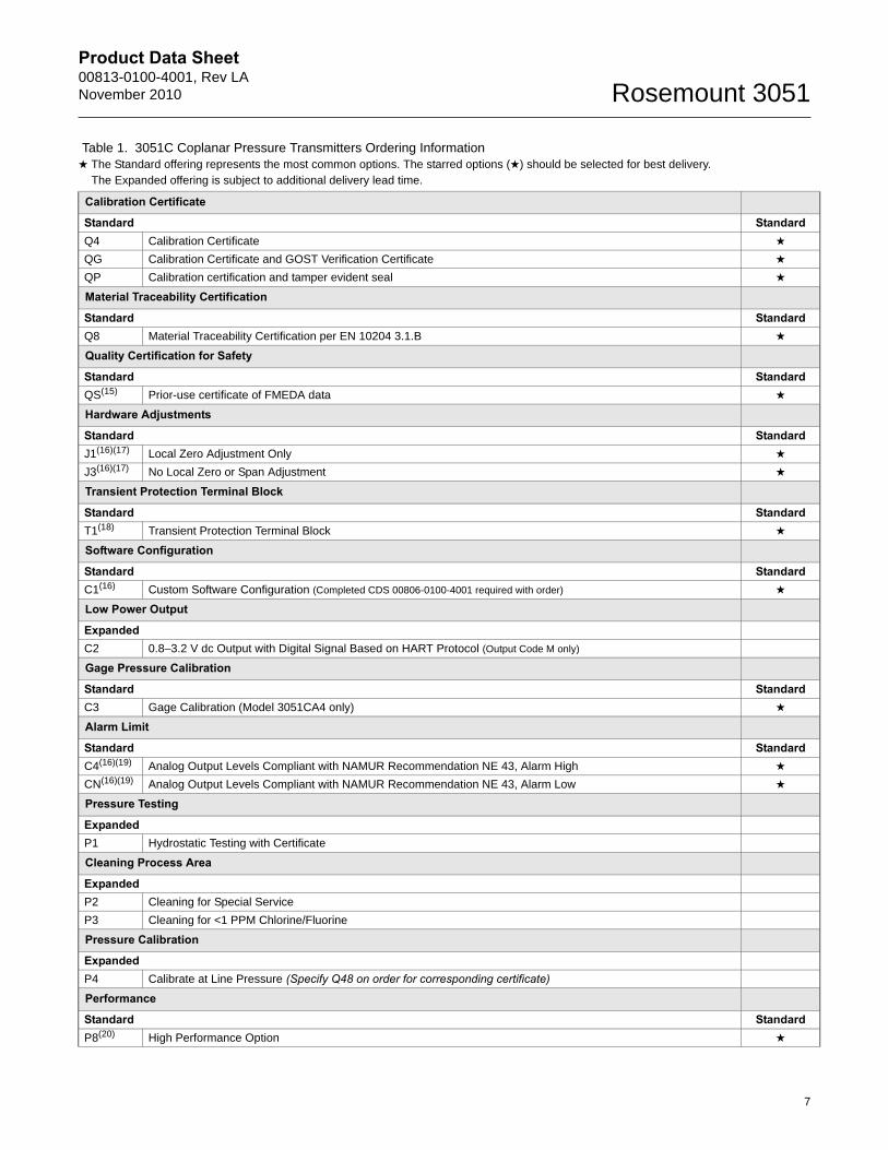
Table 1. 3051C Coplanar Pressure Transmitters Ordering Information★ The Standard offering represents the most common options. The starred options (★) should be selected for best delivery.__The Expanded offering is subject to additional delivery lead time.
6
Product Data Sheet00813-0100-4001, Rev LANovember 2010 Rosemount 3051
Calibration Certificate
Standard StandardQ4 Calibration Certificate ★
QG Calibration Certificate and GOST Verification Certificate ★
QP Calibration certification and tamper evident seal ★
Material Traceability Certification
Standard StandardQ8 Material Traceability Certification per EN 10204 3.1.B ★
Quality Certification for Safety
Standard StandardQS(15) Prior-use certificate of FMEDA data ★
Hardware Adjustments
Standard StandardJ1(16)(17) Local Zero Adjustment Only ★
J3(16)(17) No Local Zero or Span Adjustment ★
Transient Protection Terminal Block
Standard StandardT1(18) Transient Protection Terminal Block ★
Software Configuration
Standard StandardC1(16) Custom Software Configuration (Completed CDS 00806-0100-4001 required with order) ★
Low Power Output
ExpandedC2 0.8–3.2 V dc Output with Digital Signal Based on HART Protocol (Output Code M only)
Gage Pressure Calibration
Standard StandardC3 Gage Calibration (Model 3051CA4 only) ★
Alarm Limit
Standard StandardC4(16)(19) Analog Output Levels Compliant with NAMUR Recommendation NE 43, Alarm High ★
CN(16)(19) Analog Output Levels Compliant with NAMUR Recommendation NE 43, Alarm Low ★
Pressure Testing
ExpandedP1 Hydrostatic Testing with Certificate
Cleaning Process Area
ExpandedP2 Cleaning for Special Service
P3 Cleaning for <1 PPM Chlorine/Fluorine
Pressure Calibration
ExpandedP4 Calibrate at Line Pressure (Specify Q48 on order for corresponding certificate)
Performance
Standard StandardP8(20) High Performance Option ★
Table 1. 3051C Coplanar Pressure Transmitters Ordering Information★ The Standard offering represents the most common options. The starred options (★) should be selected for best delivery.__The Expanded offering is subject to additional delivery lead time.
7
Product Data Sheet00813-0100-4001, Rev LA
November 2010Rosemount 3051
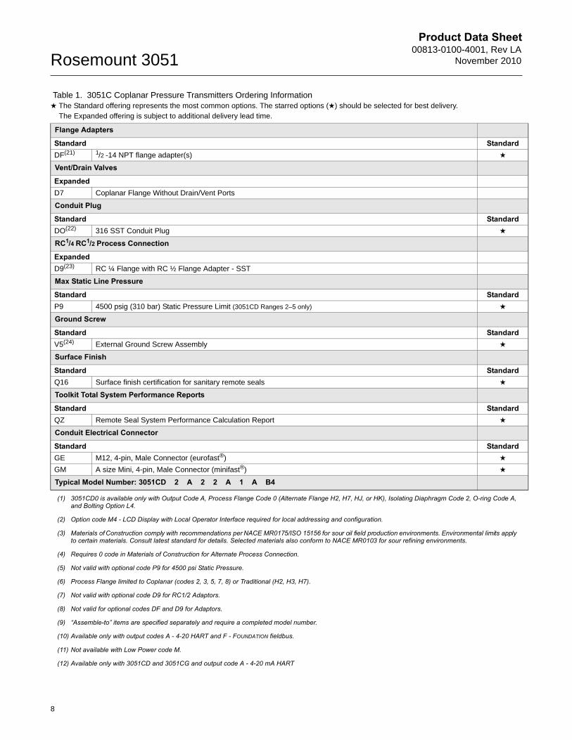
Flange Adapters
Standard StandardDF(21) 1/2 -14 NPT flange adapter(s) ★
Vent/Drain Valves
ExpandedD7 Coplanar Flange Without Drain/Vent Ports
Conduit Plug
Standard StandardDO(22) 316 SST Conduit Plug ★
RC1/4 RC1/2 Process Connection
ExpandedD9(23) RC ¼ Flange with RC ½ Flange Adapter - SST
Max Static Line Pressure
Standard StandardP9 4500 psig (310 bar) Static Pressure Limit (3051CD Ranges 2–5 only) ★
Ground Screw
Standard StandardV5(24) External Ground Screw Assembly ★
Surface Finish
Standard StandardQ16 Surface finish certification for sanitary remote seals ★
Toolkit Total System Performance Reports
Standard StandardQZ Remote Seal System Performance Calculation Report ★
Conduit Electrical Connector
Standard StandardGE M12, 4-pin, Male Connector (eurofast®) ★
GM A size Mini, 4-pin, Male Connector (minifast®) ★
Typical Model Number: 3051CD 2 A 2 2 A 1 A B4
(1) 3051CD0 is available only with Output Code A, Process Flange Code 0 (Alternate Flange H2, H7, HJ, or HK), Isolating Diaphragm Code 2, O-ring Code A, and Bolting Option L4.
(2) Option code M4 - LCD Display with Local Operator Interface required for local addressing and configuration.
(3) Materials of Construction comply with recommendations per NACE MR0175/ISO 15156 for sour oil field production environments. Environmental limits apply to certain materials. Consult latest standard for details. Selected materials also conform to NACE MR0103 for sour refining environments.
(4) Requires 0 code in Materials of Construction for Alternate Process Connection.
(5) Not valid with optional code P9 for 4500 psi Static Pressure.
(6) Process Flange limited to Coplanar (codes 2, 3, 5, 7, 8) or Traditional (H2, H3, H7).
(7) Not valid with optional code D9 for RC1/2 Adaptors.
(8) Not valid for optional codes DF and D9 for Adaptors.
(9) “Assemble-to” items are specified separately and require a completed model number.
(10) Available only with output codes A - 4-20 HART and F - FOUNDATION fieldbus.
(11) Not available with Low Power code M.
(12) Available only with 3051CD and 3051CG and output code A - 4-20 mA HART
Table 1. 3051C Coplanar Pressure Transmitters Ordering Information★ The Standard offering represents the most common options. The starred options (★) should be selected for best delivery.__The Expanded offering is subject to additional delivery lead time.
8
Product Data Sheet00813-0100-4001, Rev LANovember 2010 Rosemount 3051
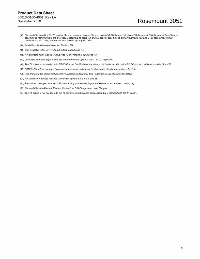
(13) Not available with Alloy C-276 isolator (3 code), tantalum isolator (5 code), all cast C-276 flanges, all plated CS flanges, all DIN flanges, all Level flanges, assemble-to manifolds (S5 and S6 codes), assemble-to seals (S1 and S2 codes), assemble-to primary elements (S3 and S4 codes), surface finish certification (Q16 code), and remote seal system report (QZ code).
(14) Available only with output code W - Profibus PA.
(15) Only available with HART 4-20 mA output (output code A).
(16) Not available with Fieldbus (output code F) or Profibus (output code W).
(17) Local zero and span adjustments are standard unless Option Code J1 or J3 is specified
(18) The T1 option is not needed with FISCO Product Certifications; transient protection is included in the FISCO product certification codes IA and IE.
(19) NAMUR-Compliant operation is pre-set at the factory and cannot be changed to standard operation in the field.
(20) High Performance Option includes 0.04% Reference Accuracy. See Performance Specifications for details.
(21) Not valid with Alternate Process Connection options S3, S4, S5, and S6.
(22) Transmitter is shipped with 316 SST conduit plug (uninstalled) in place of standard carbon steel conduit plug.
(23) Not available with Alternate Process Connection; DIN Flanges and Level Flanges.
(24) The V5 option is not needed with the T1 option; external ground screw assembly is included with the T1 option.
9
Product Data Sheet00813-0100-4001, Rev LA
November 2010Rosemount 3051
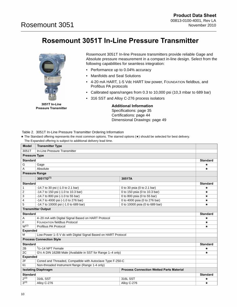
Rosemount 3051T In-Line Pressure Transmitter
Rosemount 3051T In-line Pressure transmitters provide reliable Gage and Absolute pressure measurement in a compact in-line design. Select from the following capabilities for seamless integration:
• Performance up to 0.04% accuracy
• Manifolds and Seal Solutions
• 4-20 mA HART, 1-5 Vdc HART low power, FOUNDATION fieldbus, and Profibus PA protocols
• Calibrated spans/ranges from 0.3 to 10,000 psi (10,3 mbar to 689 bar)
• 316 SST and Alloy C-276 process isolators
Additional InformationSpecifications: page 35Certifications: page 44Dimensional Drawings: page 49
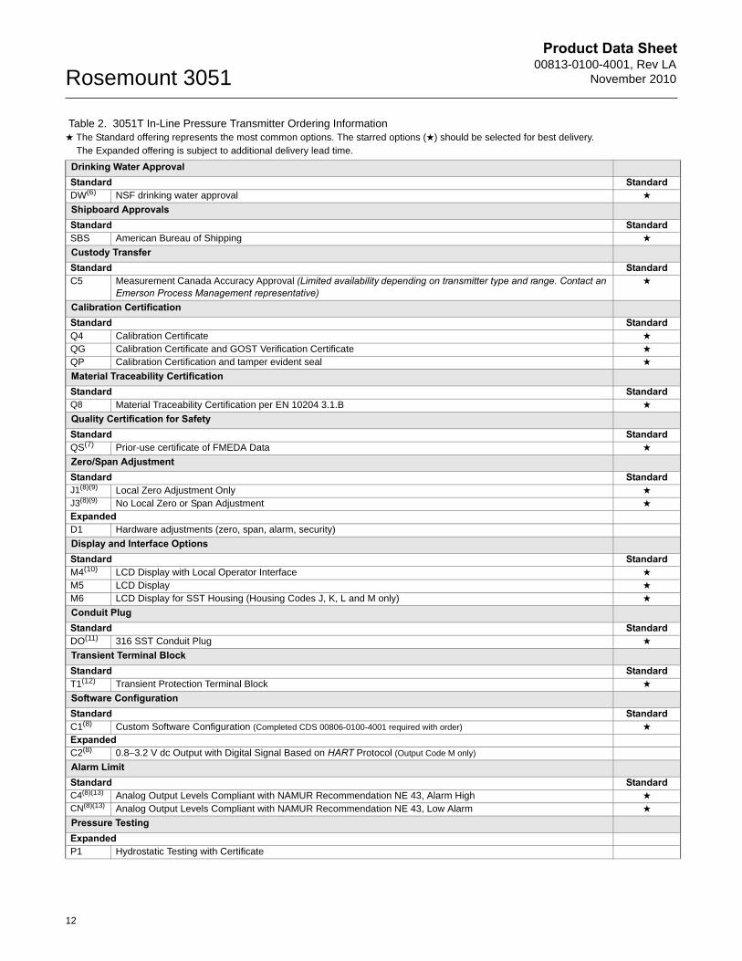
Table 2. 3051T In-Line Pressure Transmitter Ordering Information★ The Standard offering represents the most common options. The starred options (★) should be selected for best delivery.__The Expanded offering is subject to additional delivery lead time.
Model Transmitter Type3051T In-Line Pressure Transmitter
Pressure TypeStandard StandardG Gage ★
A Absolute ★
Pressure Range3051TG(1) 3051TA
Standard Standard1 -14.7 to 30 psi (-1.0 to 2.1 bar) 0 to 30 psia (0 to 2.1 bar) ★
2 -14.7 to 150 psi (-1.0 to 10.3 bar) 0 to 150 psia (0 to 10.3 bar) ★
3 -14.7 to 800 psi (-1.0 to 55 bar) 0 to 800 psia (0 to 55 bar) ★
4 -14.7 to 4000 psi (-1.0 to 276 bar) 0 to 4000 psia (0 to 276 bar) ★
5 -14.7 to 10000 psi (-1.0 to 689 bar) 0 to 10000 psia (0 to 689 bar) ★
Transmitter OutputStandard StandardA 4–20 mA with Digital Signal Based on HART Protocol ★
F FOUNDATION fieldbus Protocol ★
W(2) Profibus PA Protocol ★
ExpandedM Low-Power 1–5 V dc with Digital Signal Based on HART Protocol
Process Connection StyleStandard Standard2B 1/2–14 NPT Female ★
2C G½ A DIN 16288 Male (Available in SST for Range 1–4 only) ★
Expanded2F Coned and Threaded, Compatible with Autoclave Type F-250-C 61 Non-threaded Instrument flange (Range 1-4 only)
Isolating Diaphragm Process Connection Wetted Parts MaterialStandard Standard2(3) 316L SST 316L SST ★
3(3) Alloy C-276 Alloy C-276 ★
3051T In-LinePressure Transmitter
10
Product Data Sheet00813-0100-4001, Rev LANovember 2010 Rosemount 3051
11
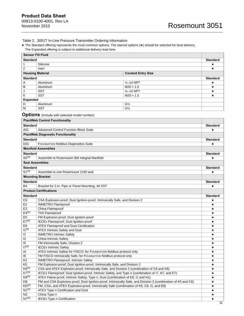
Sensor Fill FluidStandard Standard1 Silicone ★
2 Inert ★
Housing Material Conduit Entry SizeStandard StandardA Aluminum ½–14 NPT ★
B Aluminum M20 × 1.5 ★
J SST ½–14 NPT ★
K SST M20 × 1.5 ★
ExpandedD Aluminum G½M SST G½
Options (Include with selected model number)
PlantWeb Control Functionality Standard StandardA01 Advanced Control Function Block Suite ★
PlantWeb Diagnostic Functionality Standard StandardD01 FOUNDATION fieldbus Diagnostics Suite ★
Manifold AssembliesStandard StandardS5(4) Assemble to Rosemount 306 Integral Manifold ★
Seal Assemblies Standard StandardS1(4) Assemble to one Rosemount 1199 seal ★
Mounting BracketStandard StandardB4 Bracket for 2-in. Pipe or Panel Mounting, All SST ★
Product CertificationsStandard StandardC6 CSA Explosion-proof, Dust Ignition-proof, Intrinsically Safe, and Division 2 ★
E2 INMETRO Flameproof ★
E3 China Flameproof ★
E4(5) TIIS Flameproof ★
E5 FM Explosion-proof, Dust Ignition-proof ★
E7(5) IECEx Flameproof, Dust Ignition-proof ★
E8 ATEX Flameproof and Dust Certification ★
I1(5) ATEX Intrinsic Safety and Dust ★
I2 INMETRO Intrinsic Safety ★
I3 China Intrinsic Safety ★
I5 FM Intrinsically Safe, Division 2 ★
I7(5) IECEx Intrinsic Safety ★
IA ATEX Intrinsic Safety for FISCO; for FOUNDATION fieldbus protocol only ★
IE FM FISCO Intrinsically Safe; for FOUNDATION fieldbus protocol only ★
K2 INMETRO Flameproof, Intrinsic Safety ★
K5 FM Explosion-proof, Dust Ignition-proof, Intrinsically Safe, and Division 2 ★
K6(5) CSA and ATEX Explosion-proof, Intrinsically Safe, and Division 2 (combination of C6 and K8) ★
K7(5) IECEx Flameproof, Dust Ignition-proof, Intrinsic Safety, and Type n (combination of I7, N7, and E7) ★
K8(5) ATEX Flame-proof, Intrinsic Safety, Type n, Dust (combination of E8, I1 and N1) ★
KB FM and CSA Explosion-proof, Dust Ignition-proof, Intrinsically Safe, and Division 2 (combination of K5 and C6) ★
KD(5) FM, CSA, and ATEX Explosion-proof, Intrinsically Safe (combination of K5, C6, I1, and E8) ★
N1(5) ATEX Type n Certification and Dust ★
N3 China Type n ★
N7(5) IECEx Type n Certification ★
Table 2. 3051T In-Line Pressure Transmitter Ordering Information★ The Standard offering represents the most common options. The starred options (★) should be selected for best delivery.__The Expanded offering is subject to additional delivery lead time.
Product Data Sheet00813-0100-4001, Rev LA
November 2010Rosemount 3051
Drinking Water ApprovalStandard StandardDW(6) NSF drinking water approval ★
Shipboard ApprovalsStandard StandardSBS American Bureau of Shipping ★
Custody TransferStandard StandardC5 Measurement Canada Accuracy Approval (Limited availability depending on transmitter type and range. Contact an
Emerson Process Management representative)★
Calibration CertificationStandard StandardQ4 Calibration Certificate ★
QG Calibration Certificate and GOST Verification Certificate ★
QP Calibration Certification and tamper evident seal ★
Material Traceability CertificationStandard StandardQ8 Material Traceability Certification per EN 10204 3.1.B ★
Quality Certification for SafetyStandard StandardQS(7) Prior-use certificate of FMEDA Data ★
Zero/Span AdjustmentStandard StandardJ1(8)(9) Local Zero Adjustment Only ★
J3(8)(9) No Local Zero or Span Adjustment ★
ExpandedD1 Hardware adjustments (zero, span, alarm, security)
Display and Interface OptionsStandard StandardM4(10) LCD Display with Local Operator Interface ★
M5 LCD Display ★
M6 LCD Display for SST Housing (Housing Codes J, K, L and M only) ★
Conduit PlugStandard StandardDO(11) 316 SST Conduit Plug ★
Transient Terminal BlockStandard StandardT1(12) Transient Protection Terminal Block ★
Software ConfigurationStandard StandardC1(8) Custom Software Configuration (Completed CDS 00806-0100-4001 required with order) ★
ExpandedC2(8) 0.8–3.2 V dc Output with Digital Signal Based on HART Protocol (Output Code M only)
Alarm LimitStandard StandardC4(8)(13) Analog Output Levels Compliant with NAMUR Recommendation NE 43, Alarm High ★
CN(8)(13) Analog Output Levels Compliant with NAMUR Recommendation NE 43, Low Alarm ★
Pressure TestingExpandedP1 Hydrostatic Testing with Certificate
Table 2. 3051T In-Line Pressure Transmitter Ordering Information★ The Standard offering represents the most common options. The starred options (★) should be selected for best delivery.__The Expanded offering is subject to additional delivery lead time.
12
Product Data Sheet00813-0100-4001, Rev LANovember 2010 Rosemount 3051
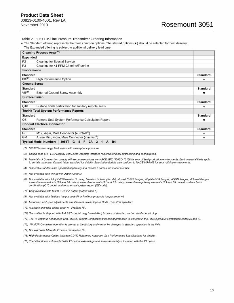
Cleaning Process Area(14)
ExpandedP2 Cleaning for Special ServiceP3 Cleaning for <1 PPM Chlorine/Fluorine
PerformanceStandard StandardP8(15) High Performance Option ★
Ground ScrewStandard StandardV5(16) External Ground Screw Assembly ★
Surface FinishStandard StandardQ16 Surface finish certification for sanitary remote seals ★
Toolkit Total System Performance ReportsStandard StandardQZ Remote Seal System Performance Calculation Report ★
Conduit Electrical ConnectorStandard StandardGE M12, 4-pin, Male Connector (eurofast®) ★
GM A size Mini, 4-pin, Male Connector (minifast®) ★
Typical Model Number: 3051T G 5 F 2A 2 1 A B4
(1) 3051TG lower range limit varies with atmospheric pressure.
(2) Option code M4 - LCD Display with Local Operator Interface required for local addressing and configuration.
(3) Materials of Construction comply with recommendations per NACE MR0175/ISO 15156 for sour oil field production environments. Environmental limits apply to certain materials. Consult latest standard for details. Selected materials also conform to NACE MR0103 for sour refining environments.
(4) “Assemble-to” items are specified separately and require a completed model number.
(5) Not available with low-power Option Code M.
(6) Not available with Alloy C-276 isolator (3 code), tantalum isolator (5 code), all cast C-276 flanges, all plated CS flanges, all DIN flanges, all Level flanges, assemble-to manifolds (S5 and S6 codes), assemble-to seals (S1 and S2 codes), assemble-to primary elements (S3 and S4 codes), surface finish certification (Q16 code), and remote seal system report (QZ code).
(7) Only available with HART 4-20 mA output (output code A).
(8) Not available with fieldbus (output code F) or Profibus protocols (output code W).
(9) Local zero and span adjustments are standard unless Option Code J1 or J3 is specified.
(10) Available only with output code W - Profibus PA.
(11) Transmitter is shipped with 316 SST conduit plug (uninstalled) in place of standard carbon steel conduit plug.
(12) The T1 option is not needed with FISCO Product Certifications; transient protection is included in the FISCO product certification codes IA and IE.
(13) NAMUR-Compliant operation is pre-set at the factory and cannot be changed to standard operation in the field.
(14) Not valid with Alternate Process Connection S5.
(15) High Performance Option includes 0.04% Reference Accuracy. See Performance Specifications for details.
(16) The V5 option is not needed with T1 option; external ground screw assembly is included with the T1 option.
Table 2. 3051T In-Line Pressure Transmitter Ordering Information★ The Standard offering represents the most common options. The starred options (★) should be selected for best delivery.__The Expanded offering is subject to additional delivery lead time.
13
Product Data Sheet00813-0100-4001, Rev LA
November 2010Rosemount 3051
14
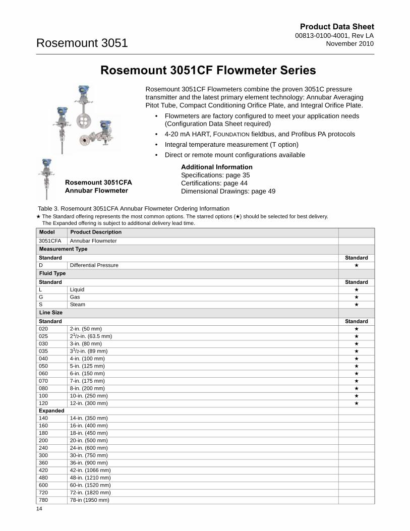
Rosemount 3051CF Flowmeter Series
Rosemount 3051CFA Annubar Flowmeter
Rosemount 3051CF Flowmeters combine the proven 3051C pressure transmitter and the latest primary element technology: Annubar Averaging Pitot Tube, Compact Conditioning Orifice Plate, and Integral Orifice Plate.
• Flowmeters are factory configured to meet your application needs (Configuration Data Sheet required)
• 4-20 mA HART, FOUNDATION fieldbus, and Profibus PA protocols
• Integral temperature measurement (T option)
• Direct or remote mount configurations available
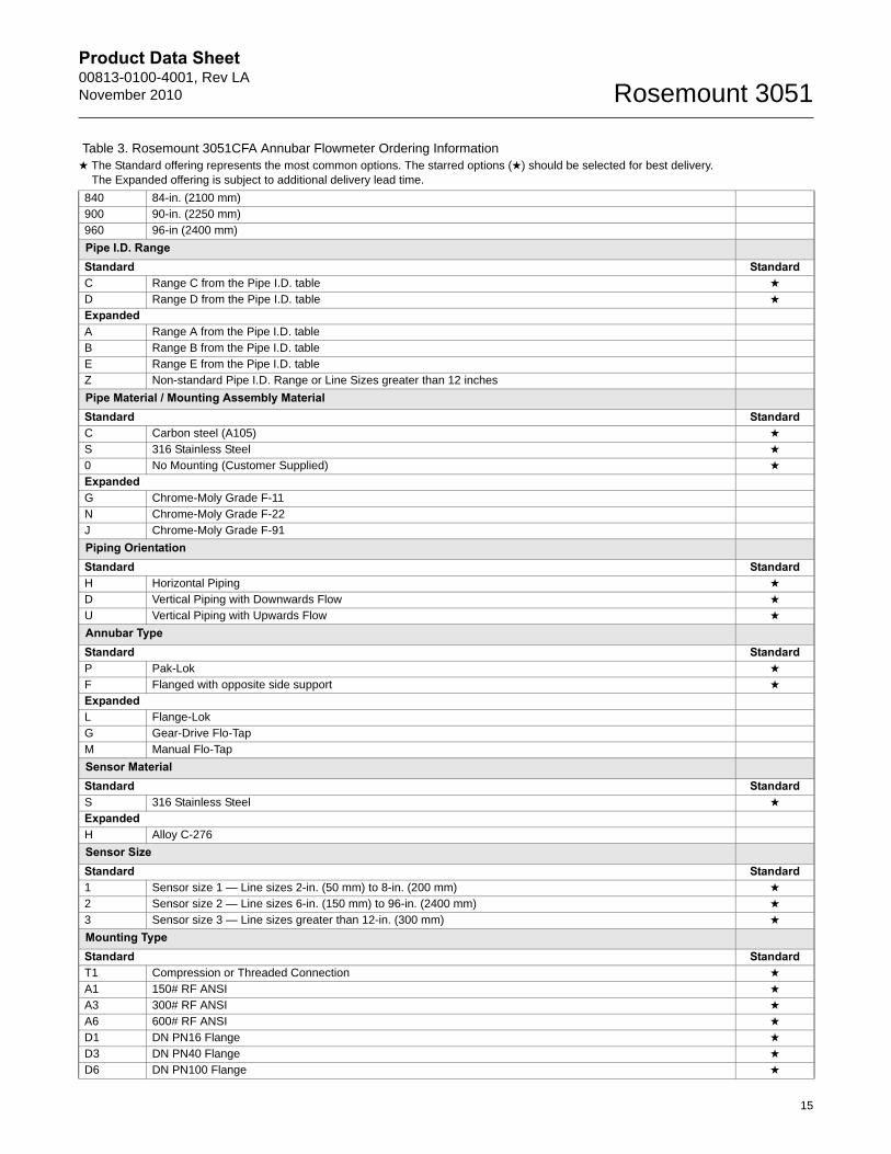
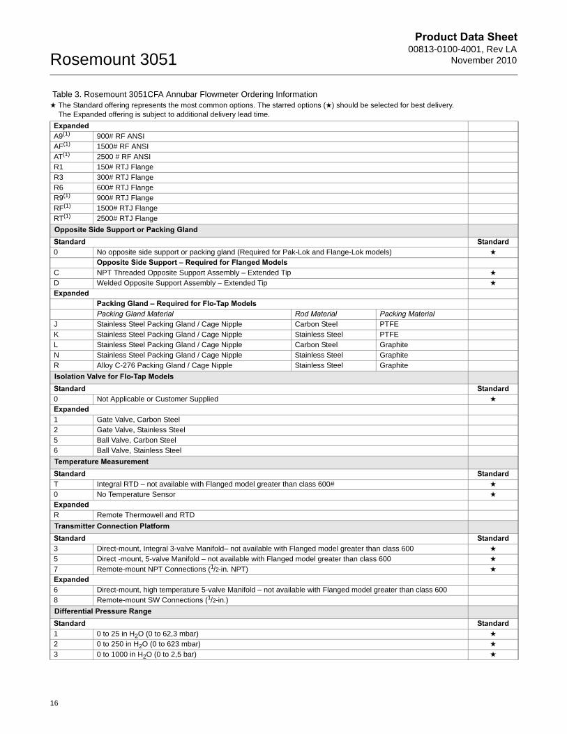
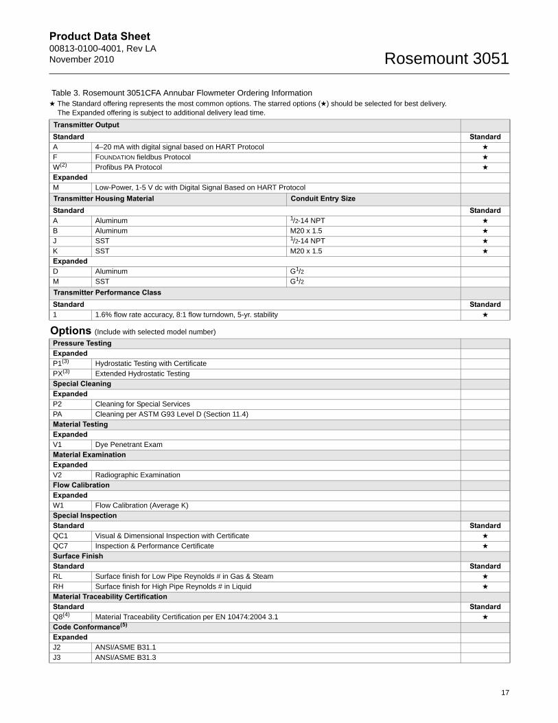
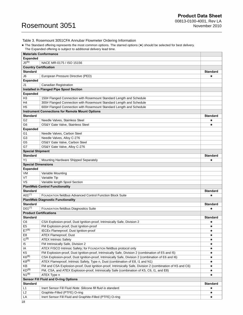
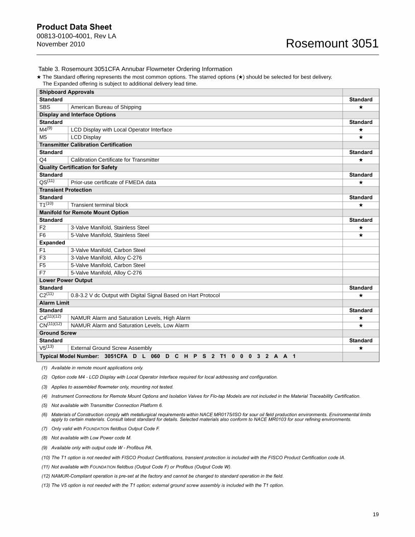
Table 3. Rosemount 3051CFA Annubar Flowmeter Ordering Information★ The Standard offering represents the most common options. The starred options (★) should be selected for best delivery.__The Expanded offering is subject to additional delivery lead time.
Model Product Description3051CFA Annubar Flowmeter
Measurement TypeStandard StandardD Differential Pressure ★
Fluid TypeStandard StandardL Liquid ★
G Gas ★
S Steam ★
Line SizeStandard Standard020 2-in. (50 mm) ★
025 21/2-in. (63.5 mm) ★
030 3-in. (80 mm) ★
035 31/2-in. (89 mm) ★
040 4-in. (100 mm) ★
050 5-in. (125 mm) ★
060 6-in. (150 mm) ★
070 7-in. (175 mm) ★
080 8-in. (200 mm) ★
100 10-in. (250 mm) ★
120 12-in. (300 mm) ★
Expanded140 14-in. (350 mm)160 16-in. (400 mm)180 18-in. (450 mm)200 20-in. (500 mm)240 24-in. (600 mm)300 30-in. (750 mm)360 36-in. (900 mm)420 42-in. (1066 mm)480 48-in. (1210 mm)600 60-in. (1520 mm)720 72-in. (1820 mm)780 78-in (1950 mm)
Additional InformationSpecifications: page 35Certifications: page 44Dimensional Drawings: page 49
Product Data Sheet00813-0100-4001, Rev LANovember 2010 Rosemount 3051
840 84-in. (2100 mm)900 90-in. (2250 mm)960 96-in (2400 mm)
Pipe I.D. Range Standard StandardC Range C from the Pipe I.D. table ★
D Range D from the Pipe I.D. table ★
ExpandedA Range A from the Pipe I.D. tableB Range B from the Pipe I.D. tableE Range E from the Pipe I.D. tableZ Non-standard Pipe I.D. Range or Line Sizes greater than 12 inches
Pipe Material / Mounting Assembly MaterialStandard StandardC Carbon steel (A105) ★
S 316 Stainless Steel ★
0 No Mounting (Customer Supplied) ★
ExpandedG Chrome-Moly Grade F-11N Chrome-Moly Grade F-22J Chrome-Moly Grade F-91
Piping OrientationStandard StandardH Horizontal Piping ★
D Vertical Piping with Downwards Flow ★
U Vertical Piping with Upwards Flow ★
Annubar TypeStandard StandardP Pak-Lok ★
F Flanged with opposite side support ★
ExpandedL Flange-LokG Gear-Drive Flo-TapM Manual Flo-Tap
Sensor MaterialStandard StandardS 316 Stainless Steel ★
ExpandedH Alloy C-276
Sensor SizeStandard Standard1 Sensor size 1 — Line sizes 2-in. (50 mm) to 8-in. (200 mm) ★
2 Sensor size 2 — Line sizes 6-in. (150 mm) to 96-in. (2400 mm) ★
3 Sensor size 3 — Line sizes greater than 12-in. (300 mm) ★
Mounting TypeStandard StandardT1 Compression or Threaded Connection ★
A1 150# RF ANSI ★
A3 300# RF ANSI ★
A6 600# RF ANSI ★
D1 DN PN16 Flange ★
D3 DN PN40 Flange ★
D6 DN PN100 Flange ★
Table 3. Rosemount 3051CFA Annubar Flowmeter Ordering Information★ The Standard offering represents the most common options. The starred options (★) should be selected for best delivery.__The Expanded offering is subject to additional delivery lead time.
15
Product Data Sheet00813-0100-4001, Rev LA
November 2010Rosemount 3051
ExpandedA9(1) 900# RF ANSIAF(1) 1500# RF ANSIAT(1) 2500 # RF ANSIR1 150# RTJ FlangeR3 300# RTJ FlangeR6 600# RTJ FlangeR9(1) 900# RTJ FlangeRF(1) 1500# RTJ FlangeRT(1) 2500# RTJ Flange
Opposite Side Support or Packing GlandStandard Standard0 No opposite side support or packing gland (Required for Pak-Lok and Flange-Lok models) ★
Opposite Side Support – Required for Flanged ModelsC NPT Threaded Opposite Support Assembly – Extended Tip ★
D Welded Opposite Support Assembly – Extended Tip ★
ExpandedPacking Gland – Required for Flo-Tap ModelsPacking Gland Material Rod Material Packing Material
J Stainless Steel Packing Gland / Cage Nipple Carbon Steel PTFEK Stainless Steel Packing Gland / Cage Nipple Stainless Steel PTFEL Stainless Steel Packing Gland / Cage Nipple Carbon Steel GraphiteN Stainless Steel Packing Gland / Cage Nipple Stainless Steel GraphiteR Alloy C-276 Packing Gland / Cage Nipple Stainless Steel Graphite
Isolation Valve for Flo-Tap ModelsStandard Standard0 Not Applicable or Customer Supplied ★
Expanded1 Gate Valve, Carbon Steel2 Gate Valve, Stainless Steel5 Ball Valve, Carbon Steel6 Ball Valve, Stainless Steel
Temperature MeasurementStandard StandardT Integral RTD – not available with Flanged model greater than class 600# ★
0 No Temperature Sensor ★
ExpandedR Remote Thermowell and RTD
Transmitter Connection PlatformStandard Standard3 Direct-mount, Integral 3-valve Manifold– not available with Flanged model greater than class 600 ★
5 Direct -mount, 5-valve Manifold – not available with Flanged model greater than class 600 ★
7 Remote-mount NPT Connections (1/2-in. NPT) ★
Expanded6 Direct-mount, high temperature 5-valve Manifold – not available with Flanged model greater than class 6008 Remote-mount SW Connections (1/2-in.)
Differential Pressure RangeStandard Standard1 0 to 25 in H2O (0 to 62,3 mbar) ★
2 0 to 250 in H2O (0 to 623 mbar) ★
3 0 to 1000 in H2O (0 to 2,5 bar) ★
Table 3. Rosemount 3051CFA Annubar Flowmeter Ordering Information★ The Standard offering represents the most common options. The starred options (★) should be selected for best delivery.__The Expanded offering is subject to additional delivery lead time.
16
Product Data Sheet00813-0100-4001, Rev LANovember 2010 Rosemount 3051
Transmitter OutputStandard StandardA 4–20 mA with digital signal based on HART Protocol ★
F FOUNDATION fieldbus Protocol ★
W(2) Profibus PA Protocol ★
ExpandedM Low-Power, 1-5 V dc with Digital Signal Based on HART Protocol
Transmitter Housing Material Conduit Entry SizeStandard StandardA Aluminum 1/2-14 NPT ★
B Aluminum M20 x 1.5 ★
J SST 1/2-14 NPT ★
K SST M20 x 1.5 ★
ExpandedD Aluminum G1/2M SST G1/2
Transmitter Performance ClassStandard Standard1 1.6% flow rate accuracy, 8:1 flow turndown, 5-yr. stability ★
Options (Include with selected model number)
Pressure TestingExpandedP1(3) Hydrostatic Testing with CertificatePX(3) Extended Hydrostatic TestingSpecial CleaningExpandedP2 Cleaning for Special ServicesPA Cleaning per ASTM G93 Level D (Section 11.4)Material TestingExpandedV1 Dye Penetrant ExamMaterial ExaminationExpandedV2 Radiographic ExaminationFlow CalibrationExpandedW1 Flow Calibration (Average K)Special InspectionStandard StandardQC1 Visual & Dimensional Inspection with Certificate ★
QC7 Inspection & Performance Certificate ★
Surface FinishStandard StandardRL Surface finish for Low Pipe Reynolds # in Gas & Steam ★
RH Surface finish for High Pipe Reynolds # in Liquid ★
Material Traceability CertificationStandard StandardQ8(4) Material Traceability Certification per EN 10474:2004 3.1 ★
Code Conformance(5)
ExpandedJ2 ANSI/ASME B31.1J3 ANSI/ASME B31.3
Table 3. Rosemount 3051CFA Annubar Flowmeter Ordering Information★ The Standard offering represents the most common options. The starred options (★) should be selected for best delivery.__The Expanded offering is subject to additional delivery lead time.
17
Product Data Sheet00813-0100-4001, Rev LA
November 2010Rosemount 3051
18
Materials ConformanceExpandedJ5(6) NACE MR-0175 / ISO 15156Country CertificationStandard StandardJ6 European Pressure Directive (PED) ★
ExpandedJ1 Canadian RegistrationInstalled in Flanged Pipe Spool SectionExpandedH3 150# Flanged Connection with Rosemount Standard Length and ScheduleH4 300# Flanged Connection with Rosemount Standard Length and ScheduleH5 600# Flanged Connection with Rosemount Standard Length and ScheduleInstrument Connections for Remote Mount OptionsStandard StandardG2 Needle Valves, Stainless Steel ★
G6 OS&Y Gate Valve, Stainless Steel ★
ExpandedG1 Needle Valves, Carbon Steel
G3 Needle Valves, Alloy C-276G5 OS&Y Gate Valve, Carbon SteelG7 OS&Y Gate Valve, Alloy C-276Special ShipmentStandard StandardY1 Mounting Hardware Shipped Separately ★
Special DimensionsExpandedVM Variable MountingVT Variable TipVS Variable length Spool SectionPlantWeb Control FunctionalityStandard StandardA01(7) FOUNDATION fieldbus Advanced Control Function Block Suite ★
PlantWeb Diagnostic FunctionalityStandard StandardD01(7) FOUNDATION fieldbus Diagnostics Suite ★
Product CertificationsStandard StandardC6 CSA Explosion-proof, Dust Ignition-proof, Intrinsically Safe, Division 2 ★
E5 FM Explosion-proof, Dust Ignition-proof ★
E7(8) IECEx Flameproof, Dust Ignition-proof ★
E8 ATEX Flameproof, Dust ★
I1(8) ATEX Intrinsic Safety ★
I5 FM Intrinsically Safe, Division 2 ★
IA ATEX FISCO Intrinsic Safety; for FOUNDATION fieldbus protocol only ★
K5 FM Explosion-proof, Dust Ignition-proof, Intrinsically Safe, Division 2 (combination of E5 and I5) ★
K6(8) CSA Explosion-proof, Dust Ignition-proof, Intrinsically Safe, Division 2 (combination of E6 and I6) ★
K8(8) ATEX Flameproof, Intrinsic Safety, Type n, Dust (combination of E8, I1 and N1) ★
KB FM and CSA Explosion-proof, Dust Ignition-proof, Intrinsically Safe, Division 2 (combination of K5 and C6) ★
KD(8) FM, CSA, and ATEX Explosion-proof, Intrinsically Safe (combination of K5, C6, I1, and E8) ★
N1(8) ATEX Type n ★
Sensor Fill Fluid and O-ring OptionsStandard StandardL1 Inert Sensor Fill Fluid Note: Silicone fill fluid is standard. ★
L2 Graphite-Filled (PTFE) O-ring ★
LA Inert Sensor Fill Fluid and Graphite-Filled (PTFE) O-ring ★
Table 3. Rosemount 3051CFA Annubar Flowmeter Ordering Information★ The Standard offering represents the most common options. The starred options (★) should be selected for best delivery.__The Expanded offering is subject to additional delivery lead time.
Product Data Sheet00813-0100-4001, Rev LANovember 2010 Rosemount 3051
19
Shipboard ApprovalsStandard StandardSBS American Bureau of Shipping ★
Display and Interface OptionsStandard StandardM4(9) LCD Display with Local Operator Interface ★
M5 LCD Display ★
Transmitter Calibration CertificationStandard StandardQ4 Calibration Certificate for Transmitter ★
Quality Certification for SafetyStandard StandardQS(11) Prior-use certificate of FMEDA data ★
Transient ProtectionStandard StandardT1(10) Transient terminal block ★
Manifold for Remote Mount OptionStandard StandardF2 3-Valve Manifold, Stainless Steel ★
F6 5-Valve Manifold, Stainless Steel ★
ExpandedF1 3-Valve Manifold, Carbon SteelF3 3-Valve Manifold, Alloy C-276 F5 5-Valve Manifold, Carbon SteelF7 5-Valve Manifold, Alloy C-276Lower Power OutputStandard StandardC2(11) 0.8-3.2 V dc Output with Digital Signal Based on Hart Protocol ★
Alarm LimitStandard StandardC4(11)(12) NAMUR Alarm and Saturation Levels, High Alarm ★
CN(11)(12) NAMUR Alarm and Saturation Levels, Low Alarm ★
Ground ScrewStandard StandardV5(13) External Ground Screw Assembly ★
Typical Model Number: 3051CFA D L 060 D C H P S 2 T1 0 0 0 3 2 A A 1
(1) Available in remote mount applications only.
(2) Option code M4 - LCD Display with Local Operator Interface required for local addressing and configuration.
(3) Applies to assembled flowmeter only, mounting not tested.
(4) Instrument Connections for Remote Mount Options and Isolation Valves for Flo-tap Models are not included in the Material Traceability Certification.
(5) Not available with Transmitter Connection Platform 6.
(6) Materials of Construction comply with metallurgical requirements within NACE MR0175/ISO for sour oil field production environments. Environmental limits apply to certain materials. Consult latest standard for details. Selected materials also conform to NACE MR0103 for sour refining environments.
(7) Only valid with FOUNDATION fieldbus Output Code F.
(8) Not available with Low Power code M.
(9) Available only with output code W - Profibus PA.
(10) The T1 option is not needed with FISCO Product Certifications, transient protection is included with the FISCO Product Certification code IA.
(11) Not available with FOUNDATION fieldbus (Output Code F) or Profibus (Output Code W).
(12) NAMUR-Compliant operation is pre-set at the factory and cannot be changed to standard operation in the field.
(13) The V5 option is not needed with the T1 option; external ground screw assembly is included with the T1 option.
Table 3. Rosemount 3051CFA Annubar Flowmeter Ordering Information★ The Standard offering represents the most common options. The starred options (★) should be selected for best delivery.__The Expanded offering is subject to additional delivery lead time.
Product Data Sheet00813-0100-4001, Rev LA
November 2010Rosemount 3051
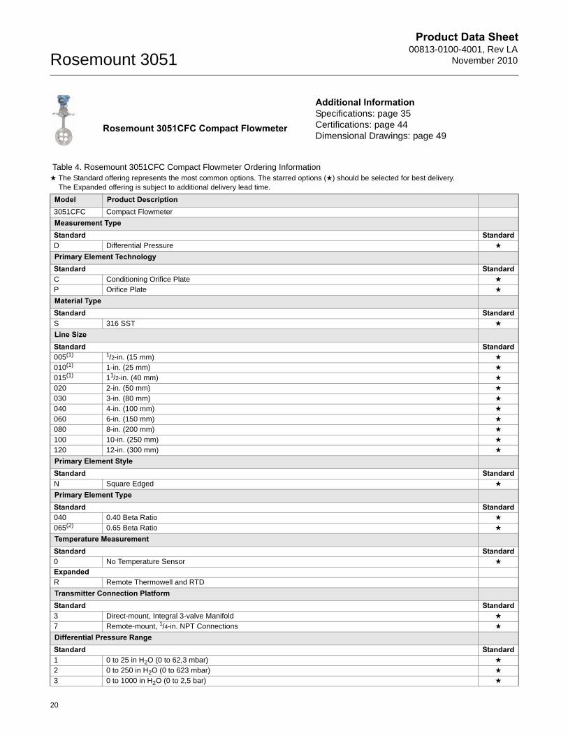
Rosemount 3051CFC Compact Flowmeter
Table 4. Rosemount 3051CFC Compact Flowmeter Ordering Information★ The Standard offering represents the most common options. The starred options (★) should be selected for best delivery.__The Expanded offering is subject to additional delivery lead time.
Model Product Description3051CFC Compact Flowmeter
Measurement TypeStandard StandardD Differential Pressure ★
Primary Element TechnologyStandard StandardC Conditioning Orifice Plate ★
P Orifice Plate ★
Material TypeStandard StandardS 316 SST ★
Line SizeStandard Standard005(1) 1/2-in. (15 mm) ★
010(1) 1-in. (25 mm) ★
015(1) 11/2-in. (40 mm) ★
020 2-in. (50 mm) ★
030 3-in. (80 mm) ★
040 4-in. (100 mm) ★
060 6-in. (150 mm) ★
080 8-in. (200 mm) ★
100 10-in. (250 mm) ★
120 12-in. (300 mm) ★
Primary Element StyleStandard StandardN Square Edged ★
Primary Element TypeStandard Standard040 0.40 Beta Ratio ★
065(2) 0.65 Beta Ratio ★
Temperature MeasurementStandard Standard0 No Temperature Sensor ★
ExpandedR Remote Thermowell and RTD
Transmitter Connection PlatformStandard Standard3 Direct-mount, Integral 3-valve Manifold ★
7 Remote-mount, 1/4-in. NPT Connections ★
Differential Pressure RangeStandard Standard1 0 to 25 in H2O (0 to 62,3 mbar) ★
2 0 to 250 in H2O (0 to 623 mbar) ★
3 0 to 1000 in H2O (0 to 2,5 bar) ★
Additional InformationSpecifications: page 35Certifications: page 44Dimensional Drawings: page 49
20
Product Data Sheet00813-0100-4001, Rev LANovember 2010 Rosemount 3051
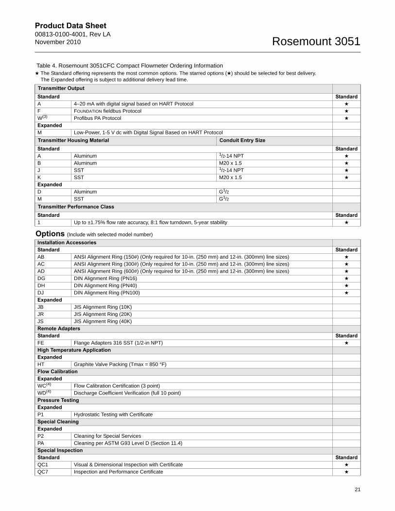
Transmitter OutputStandard StandardA 4–20 mA with digital signal based on HART Protocol ★
F FOUNDATION fieldbus Protocol ★
W(3) Profibus PA Protocol ★
ExpandedM Low-Power, 1-5 V dc with Digital Signal Based on HART Protocol
Transmitter Housing Material Conduit Entry SizeStandard StandardA Aluminum 1/2-14 NPT ★
B Aluminum M20 x 1.5 ★
J SST 1/2-14 NPT ★
K SST M20 x 1.5 ★
ExpandedD Aluminum G1/2M SST G1/2
Transmitter Performance ClassStandard Standard1 Up to ±1.75% flow rate accuracy, 8:1 flow turndown, 5-year stability ★
Options (Include with selected model number)
Installation AccessoriesStandard StandardAB ANSI Alignment Ring (150#) (Only required for 10-in. (250 mm) and 12-in. (300mm) line sizes) ★
AC ANSI Alignment Ring (300#) (Only required for 10-in. (250 mm) and 12-in. (300mm) line sizes) ★
AD ANSI Alignment Ring (600#) (Only required for 10-in. (250 mm) and 12-in. (300mm) line sizes) ★
DG DIN Alignment Ring (PN16) ★
DH DIN Alignment Ring (PN40) ★
DJ DIN Alignment Ring (PN100) ★
ExpandedJB JIS Alignment Ring (10K)JR JIS Alignment Ring (20K)JS JIS Alignment Ring (40K)Remote AdaptersStandard StandardFE Flange Adapters 316 SST (1/2-in NPT) ★
High Temperature ApplicationExpandedHT Graphite Valve Packing (Tmax = 850 °F)Flow CalibrationExpandedWC(4) Flow Calibration Certification (3 point)WD(4) Discharge Coefficient Verification (full 10 point)Pressure TestingExpandedP1 Hydrostatic Testing with CertificateSpecial CleaningExpandedP2 Cleaning for Special ServicesPA Cleaning per ASTM G93 Level D (Section 11.4)Special InspectionStandard StandardQC1 Visual & Dimensional Inspection with Certificate ★
QC7 Inspection and Performance Certificate ★
Table 4. Rosemount 3051CFC Compact Flowmeter Ordering Information★ The Standard offering represents the most common options. The starred options (★) should be selected for best delivery.__The Expanded offering is subject to additional delivery lead time.
21
Product Data Sheet00813-0100-4001, Rev LA
November 2010Rosemount 3051
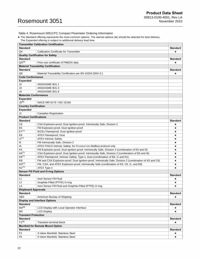
Transmitter Calibration CertificationStandard StandardQ4 Calibration Certificate for Transmitter ★
Quality Certification for SafetyStandard StandardQS(5) Prior-use certificate of FMEDA data ★
Material Traceability CertificationStandard StandardQ8 Material Traceability Certification per EN 10204:2004 3.1 ★
Code ConformanceExpandedJ2 ANSI/ASME B31.1J3 ANSI/ASME B31.3J4 ANSI/ASME B31.8Materials ConformanceExpandedJ5(6) NACE MR-0175 / ISO 15156Country CertificationExpandedJ1 Canadian RegistrationProduct CertificationsStandard StandardC6 CSA Explosion-proof, Dust Ignition-proof, Intrinsically Safe, Division 2 ★
E5 FM Explosion-proof, Dust Ignition-proof ★
E7(7) IECEx Flameproof, Dust Ignition-proof ★
E8 ATEX Flameproof, Dust ★
I1(7) ATEX Intrinsic Safety ★
I5 FM Intrinsically Safe, Division 2 ★
IA ATEX FISCO Intrinsic Safety; for FOUNDATION fieldbus protocol only ★
K5 FM Explosion-proof, Dust Ignition-proof, Intrinsically Safe, Division 2 (combination of E5 and I5) ★
K6(7) CSA Explosion-proof, Dust Ignition-proof, Intrinsically Safe, Division 2 (combination of E6 and I6) ★
K8(7) ATEX Flameproof, Intrinsic Safety, Type n, Dust (combination of E8, I1 and N1) ★
KB FM and CSA Explosion-proof, Dust Ignition-proof, Intrinsically Safe, Division 2 (combination of K5 and C6) ★
KD(7) FM, CSA, and ATEX Explosion-proof, Intrinsically Safe (combination of K5, C6, I1, and E8) ★
N1(7) ATEX Type n ★
Sensor Fill Fluid and O-ring OptionsStandard StandardL1 Inert Sensor Fill Fluid ★
L2 Graphite-Filled (PTFE) O-ring ★
LA Inert Sensor Fill Fluid and Graphite-Filled (PTFE) O-ring ★
Shipboard ApprovalsStandard StandardSBS American Bureau of Shipping ★
Display and Interface OptionsStandard StandardM4(8) LCD Display with Local Operator Interface ★
M5 LCD Display ★
Transient ProtectionStandard StandardT1(9) Transient terminal block ★
Manifold for Remote Mount OptionStandard StandardF2 3-Valve Manifold, Stainless Steel ★
F6 5-Valve Manifold, Stainless Steel ★
Table 4. Rosemount 3051CFC Compact Flowmeter Ordering Information★ The Standard offering represents the most common options. The starred options (★) should be selected for best delivery.__The Expanded offering is subject to additional delivery lead time.
22
Product Data Sheet00813-0100-4001, Rev LANovember 2010 Rosemount 3051
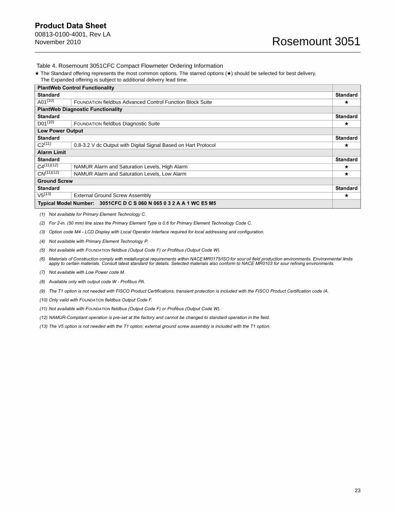
PlantWeb Control FunctionalityStandard StandardA01(10) FOUNDATION fieldbus Advanced Control Function Block Suite ★
PlantWeb Diagnostic FunctionalityStandard StandardD01(10) FOUNDATION fieldbus Diagnostic Suite ★
Low Power OutputStandard StandardC2(11) 0.8-3.2 V dc Output with Digital Signal Based on Hart Protocol ★
Alarm LimitStandard StandardC4(11)(12) NAMUR Alarm and Saturation Levels, High Alarm ★
CN(11)(12) NAMUR Alarm and Saturation Levels, Low Alarm ★
Ground ScrewStandard StandardV5(13) External Ground Screw Assembly ★
Typical Model Number: 3051CFC D C S 060 N 065 0 3 2 A A 1 WC E5 M5
(1) Not available for Primary Element Technology C.
(2) For 2-in. (50 mm) line sizes the Primary Element Type is 0.6 for Primary Element Technology Code C.
(3) Option code M4 - LCD Display with Local Operator Interface required for local addressing and configuration.
(4) Not available with Primary Element Technology P.
(5) Not available with FOUNDATION fieldbus (Output Code F) or Profibus (Output Code W).
(6) Materials of Construction comply with metallurgical requirements within NACE MR0175/ISO for sour oil field production environments. Environmental limits apply to certain materials. Consult latest standard for details. Selected materials also conform to NACE MR0103 for sour refining environments.
(7) Not available with Low Power code M.
(8) Available only with output code W - Profibus PA.
(9) The T1 option is not needed with FISCO Product Certifications, transient protection is included with the FISCO Product Certification code IA.
(10) Only valid with FOUNDATION fieldbus Output Code F.
(11) Not available with FOUNDATION fieldbus (Output Code F) or Profibus (Output Code W).
(12) NAMUR-Compliant operation is pre-set at the factory and cannot be changed to standard operation in the field.
(13) The V5 option is not needed with the T1 option; external ground screw assembly is included with the T1 option.
Table 4. Rosemount 3051CFC Compact Flowmeter Ordering Information★ The Standard offering represents the most common options. The starred options (★) should be selected for best delivery.__The Expanded offering is subject to additional delivery lead time.
23
Product Data Sheet00813-0100-4001, Rev LA
November 2010Rosemount 3051
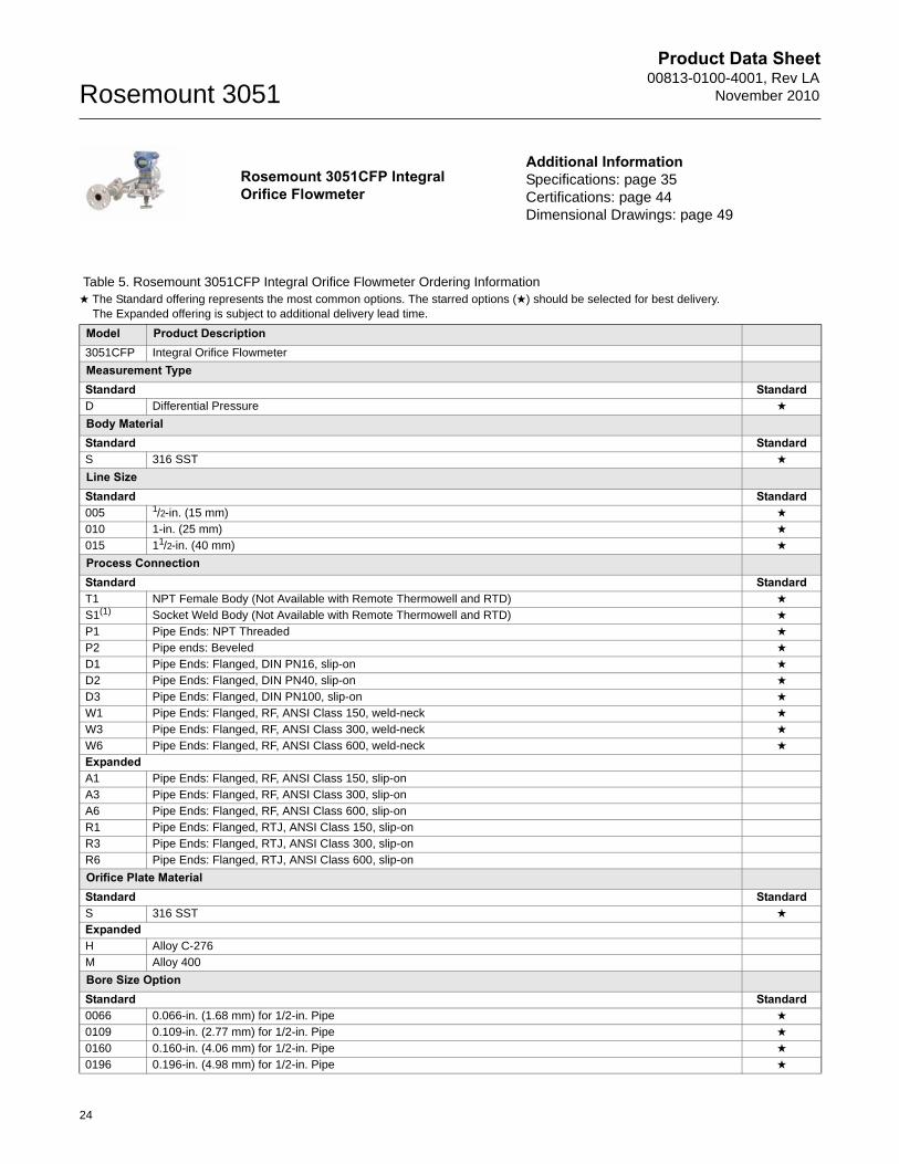
Rosemount 3051CFP Integral Orifice Flowmeter
Table 5. Rosemount 3051CFP Integral Orifice Flowmeter Ordering Information★ The Standard offering represents the most common options. The starred options (★) should be selected for best delivery.__The Expanded offering is subject to additional delivery lead time.
Model Product Description3051CFP Integral Orifice Flowmeter
Measurement TypeStandard StandardD Differential Pressure ★
Body MaterialStandard StandardS 316 SST ★
Line SizeStandard Standard005 1/2-in. (15 mm) ★
010 1-in. (25 mm) ★
015 11/2-in. (40 mm) ★
Process ConnectionStandard StandardT1 NPT Female Body (Not Available with Remote Thermowell and RTD) ★
S1(1) Socket Weld Body (Not Available with Remote Thermowell and RTD) ★
P1 Pipe Ends: NPT Threaded ★
P2 Pipe ends: Beveled ★
D1 Pipe Ends: Flanged, DIN PN16, slip-on ★
D2 Pipe Ends: Flanged, DIN PN40, slip-on ★
D3 Pipe Ends: Flanged, DIN PN100, slip-on ★
W1 Pipe Ends: Flanged, RF, ANSI Class 150, weld-neck ★
W3 Pipe Ends: Flanged, RF, ANSI Class 300, weld-neck ★
W6 Pipe Ends: Flanged, RF, ANSI Class 600, weld-neck ★
ExpandedA1 Pipe Ends: Flanged, RF, ANSI Class 150, slip-onA3 Pipe Ends: Flanged, RF, ANSI Class 300, slip-onA6 Pipe Ends: Flanged, RF, ANSI Class 600, slip-onR1 Pipe Ends: Flanged, RTJ, ANSI Class 150, slip-onR3 Pipe Ends: Flanged, RTJ, ANSI Class 300, slip-onR6 Pipe Ends: Flanged, RTJ, ANSI Class 600, slip-on
Orifice Plate MaterialStandard StandardS 316 SST ★
ExpandedH Alloy C-276M Alloy 400
Bore Size OptionStandard Standard0066 0.066-in. (1.68 mm) for 1/2-in. Pipe ★
0109 0.109-in. (2.77 mm) for 1/2-in. Pipe ★
0160 0.160-in. (4.06 mm) for 1/2-in. Pipe ★
0196 0.196-in. (4.98 mm) for 1/2-in. Pipe ★
Additional InformationSpecifications: page 35Certifications: page 44Dimensional Drawings: page 49
24
Product Data Sheet00813-0100-4001, Rev LANovember 2010 Rosemount 3051
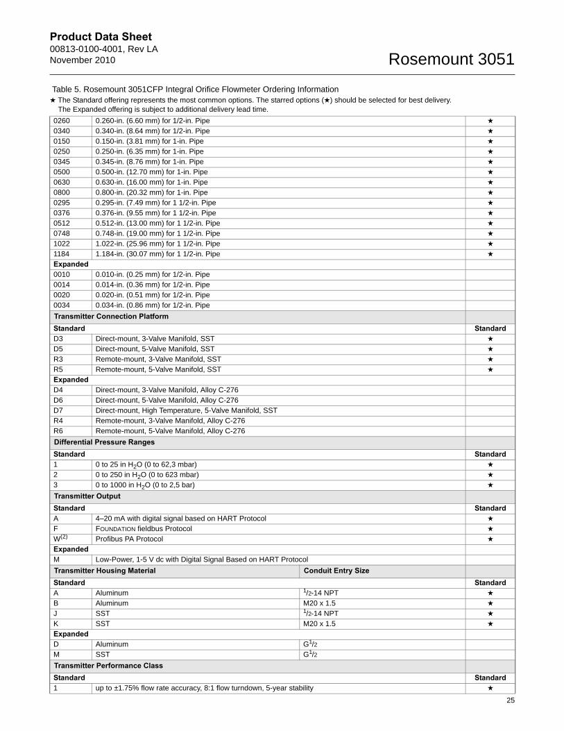
25
0260 0.260-in. (6.60 mm) for 1/2-in. Pipe ★
0340 0.340-in. (8.64 mm) for 1/2-in. Pipe ★
0150 0.150-in. (3.81 mm) for 1-in. Pipe ★
0250 0.250-in. (6.35 mm) for 1-in. Pipe ★
0345 0.345-in. (8.76 mm) for 1-in. Pipe ★
0500 0.500-in. (12.70 mm) for 1-in. Pipe ★
0630 0.630-in. (16.00 mm) for 1-in. Pipe ★
0800 0.800-in. (20.32 mm) for 1-in. Pipe ★
0295 0.295-in. (7.49 mm) for 1 1/2-in. Pipe ★
0376 0.376-in. (9.55 mm) for 1 1/2-in. Pipe ★
0512 0.512-in. (13.00 mm) for 1 1/2-in. Pipe ★
0748 0.748-in. (19.00 mm) for 1 1/2-in. Pipe ★
1022 1.022-in. (25.96 mm) for 1 1/2-in. Pipe ★
1184 1.184-in. (30.07 mm) for 1 1/2-in. Pipe ★
Expanded0010 0.010-in. (0.25 mm) for 1/2-in. Pipe0014 0.014-in. (0.36 mm) for 1/2-in. Pipe0020 0.020-in. (0.51 mm) for 1/2-in. Pipe0034 0.034-in. (0.86 mm) for 1/2-in. Pipe
Transmitter Connection PlatformStandard StandardD3 Direct-mount, 3-Valve Manifold, SST ★
D5 Direct-mount, 5-Valve Manifold, SST ★
R3 Remote-mount, 3-Valve Manifold, SST ★
R5 Remote-mount, 5-Valve Manifold, SST ★
ExpandedD4 Direct-mount, 3-Valve Manifold, Alloy C-276D6 Direct-mount, 5-Valve Manifold, Alloy C-276D7 Direct-mount, High Temperature, 5-Valve Manifold, SSTR4 Remote-mount, 3-Valve Manifold, Alloy C-276R6 Remote-mount, 5-Valve Manifold, Alloy C-276
Differential Pressure RangesStandard Standard1 0 to 25 in H2O (0 to 62,3 mbar) ★
2 0 to 250 in H2O (0 to 623 mbar) ★
3 0 to 1000 in H2O (0 to 2,5 bar) ★
Transmitter OutputStandard StandardA 4–20 mA with digital signal based on HART Protocol ★
F FOUNDATION fieldbus Protocol ★
W(2) Profibus PA Protocol ★
ExpandedM Low-Power, 1-5 V dc with Digital Signal Based on HART Protocol
Transmitter Housing Material Conduit Entry SizeStandard StandardA Aluminum 1/2-14 NPT ★
B Aluminum M20 x 1.5 ★
J SST 1/2-14 NPT ★
K SST M20 x 1.5 ★
ExpandedD Aluminum G1/2M SST G1/2
Transmitter Performance ClassStandard Standard1 up to ±1.75% flow rate accuracy, 8:1 flow turndown, 5-year stability ★
Table 5. Rosemount 3051CFP Integral Orifice Flowmeter Ordering Information★ The Standard offering represents the most common options. The starred options (★) should be selected for best delivery.__The Expanded offering is subject to additional delivery lead time.
Product Data Sheet00813-0100-4001, Rev LA
November 2010Rosemount 3051
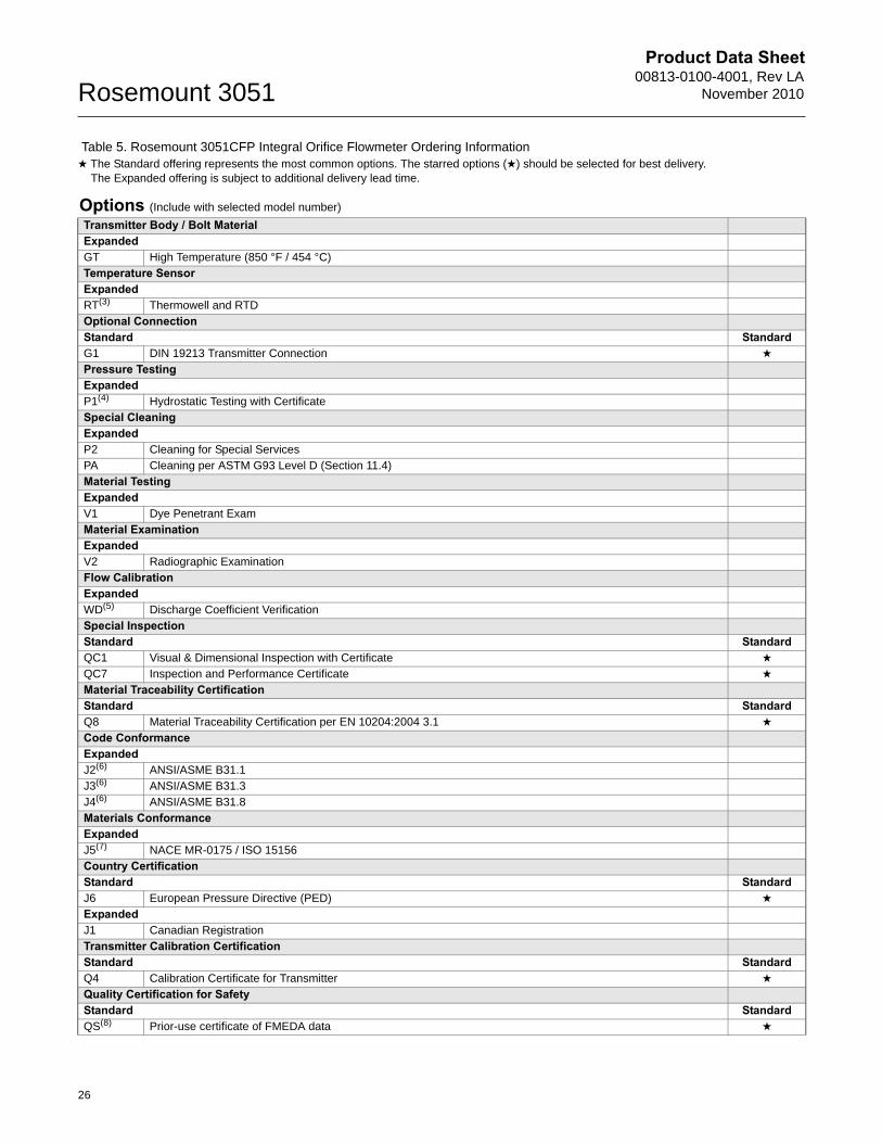
Options (Include with selected model number)
Transmitter Body / Bolt MaterialExpandedGT High Temperature (850 °F / 454 °C)Temperature SensorExpandedRT(3) Thermowell and RTDOptional ConnectionStandard StandardG1 DIN 19213 Transmitter Connection ★
Pressure TestingExpandedP1(4) Hydrostatic Testing with CertificateSpecial CleaningExpandedP2 Cleaning for Special ServicesPA Cleaning per ASTM G93 Level D (Section 11.4)Material TestingExpandedV1 Dye Penetrant ExamMaterial ExaminationExpandedV2 Radiographic ExaminationFlow CalibrationExpandedWD(5) Discharge Coefficient VerificationSpecial InspectionStandard StandardQC1 Visual & Dimensional Inspection with Certificate ★
QC7 Inspection and Performance Certificate ★
Material Traceability CertificationStandard StandardQ8 Material Traceability Certification per EN 10204:2004 3.1 ★
Code ConformanceExpandedJ2(6) ANSI/ASME B31.1J3(6) ANSI/ASME B31.3J4(6) ANSI/ASME B31.8Materials ConformanceExpandedJ5(7) NACE MR-0175 / ISO 15156Country CertificationStandard StandardJ6 European Pressure Directive (PED) ★
ExpandedJ1 Canadian RegistrationTransmitter Calibration CertificationStandard StandardQ4 Calibration Certificate for Transmitter ★
Quality Certification for SafetyStandard StandardQS(8) Prior-use certificate of FMEDA data ★
Table 5. Rosemount 3051CFP Integral Orifice Flowmeter Ordering Information★ The Standard offering represents the most common options. The starred options (★) should be selected for best delivery.__The Expanded offering is subject to additional delivery lead time.
26
Product Data Sheet00813-0100-4001, Rev LANovember 2010 Rosemount 3051
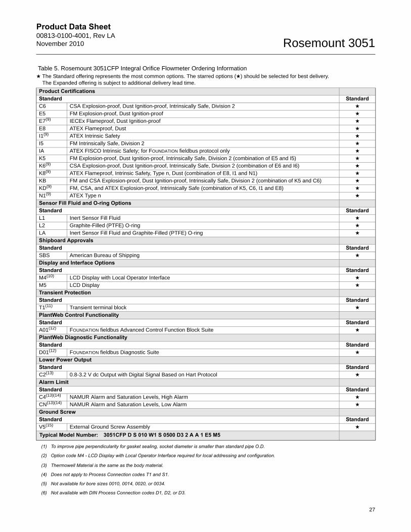
Product CertificationsStandard StandardC6 CSA Explosion-proof, Dust Ignition-proof, Intrinsically Safe, Division 2 ★
E5 FM Explosion-proof, Dust Ignition-proof ★
E7(9) IECEx Flameproof, Dust Ignition-proof ★
E8 ATEX Flameproof, Dust ★
I1(9) ATEX Intrinsic Safety ★
I5 FM Intrinsically Safe, Division 2 ★
IA ATEX FISCO Intrinsic Safety; for FOUNDATION fieldbus protocol only ★
K5 FM Explosion-proof, Dust Ignition-proof, Intrinsically Safe, Division 2 (combination of E5 and I5) ★
K6(9) CSA Explosion-proof, Dust Ignition-proof, Intrinsically Safe, Division 2 (combination of E6 and I6) ★
K8(9) ATEX Flameproof, Intrinsic Safety, Type n, Dust (combination of E8, I1 and N1) ★
KB FM and CSA Explosion-proof, Dust Ignition-proof, Intrinsically Safe, Division 2 (combination of K5 and C6) ★
KD(9) FM, CSA, and ATEX Explosion-proof, Intrinsically Safe (combination of K5, C6, I1 and E8) ★
N1(9) ATEX Type n ★
Sensor Fill Fluid and O-ring OptionsStandard StandardL1 Inert Sensor Fill Fluid ★
L2 Graphite-Filled (PTFE) O-ring ★
LA Inert Sensor Fill Fluid and Graphite-Filled (PTFE) O-ring ★
Shipboard ApprovalsStandard StandardSBS American Bureau of Shipping ★
Display and Interface OptionsStandard StandardM4(10) LCD Display with Local Operator Interface ★
M5 LCD Display ★
Transient ProtectionStandard StandardT1(11) Transient terminal block ★
PlantWeb Control FunctionalityStandard StandardA01(12) FOUNDATION fieldbus Advanced Control Function Block Suite ★
PlantWeb Diagnostic FunctionalityStandard StandardD01(12) FOUNDATION fieldbus Diagnostic Suite ★
Lower Power OutputStandard StandardC2(13) 0.8-3.2 V dc Output with Digital Signal Based on Hart Protocol ★
Alarm LimitStandard StandardC4(13)(14) NAMUR Alarm and Saturation Levels, High Alarm ★
CN(13)(14) NAMUR Alarm and Saturation Levels, Low Alarm ★
Ground ScrewStandard StandardV5(15) External Ground Screw Assembly ★
Typical Model Number: 3051CFP D S 010 W1 S 0500 D3 2 A A 1 E5 M5
(1) To improve pipe perpendicularity for gasket sealing, socket diameter is smaller than standard pipe O.D.
(2) Option code M4 - LCD Display with Local Operator Interface required for local addressing and configuration.
(3) Thermowell Material is the same as the body material.
(4) Does not apply to Process Connection codes T1 and S1.
(5) Not available for bore sizes 0010, 0014, 0020, or 0034.
(6) Not available with DIN Process Connection codes D1, D2, or D3.
Table 5. Rosemount 3051CFP Integral Orifice Flowmeter Ordering Information★ The Standard offering represents the most common options. The starred options (★) should be selected for best delivery.__The Expanded offering is subject to additional delivery lead time.
27
Product Data Sheet00813-0100-4001, Rev LA
November 2010Rosemount 3051
(7) Materials of Construction comply with metallurgical requirements within NACE MR0175/ISO for sour oil field production environments. Environmental limits apply to certain materials. Consult latest standard for details. Selected materials also conform to NACE MR0103 for sour refining environments.
(8) Not available with FOUNDATION fieldbus (Output Code F) or Profibus (Output Code W).
(9) Not available with Low Power code M.
(10) Available only with output code W - Profibus PA.
(11) The T1 option is not needed with FISCO Product Certifications, transient protection is included with the FISCO Product Certification code IA.
(12) Only valid with FOUNDATION fieldbus Output Code F.
(13) Not available with FOUNDATION fieldbus (Output Code F) or Profibus (Output Code W).
(14) NAMUR-Compliant operation is pre-set at the factory and cannot be changed to standard operation in the field.
(15) The V5 option is not needed with the T1 option; external ground screw assembly is included with the T1 option.
28
Product Data Sheet00813-0100-4001, Rev LANovember 2010 Rosemount 3051
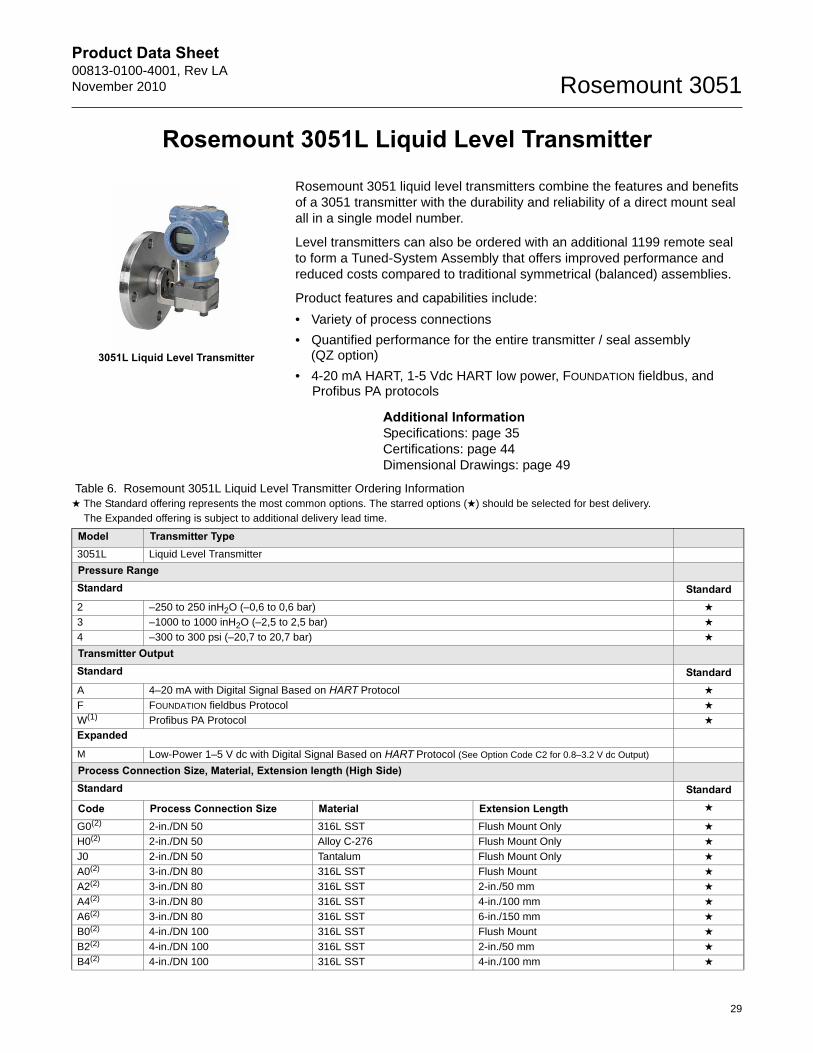
Rosemount 3051L Liquid Level Transmitter
Rosemount 3051 liquid level transmitters combine the features and benefits of a 3051 transmitter with the durability and reliability of a direct mount seal all in a single model number.
Level transmitters can also be ordered with an additional 1199 remote seal to form a Tuned-System Assembly that offers improved performance and reduced costs compared to traditional symmetrical (balanced) assemblies.
Product features and capabilities include:
• Variety of process connections
• Quantified performance for the entire transmitter / seal assembly (QZ option)
• 4-20 mA HART, 1-5 Vdc HART low power, FOUNDATION fieldbus, and Profibus PA protocols
Additional InformationSpecifications: page 35Certifications: page 44Dimensional Drawings: page 49
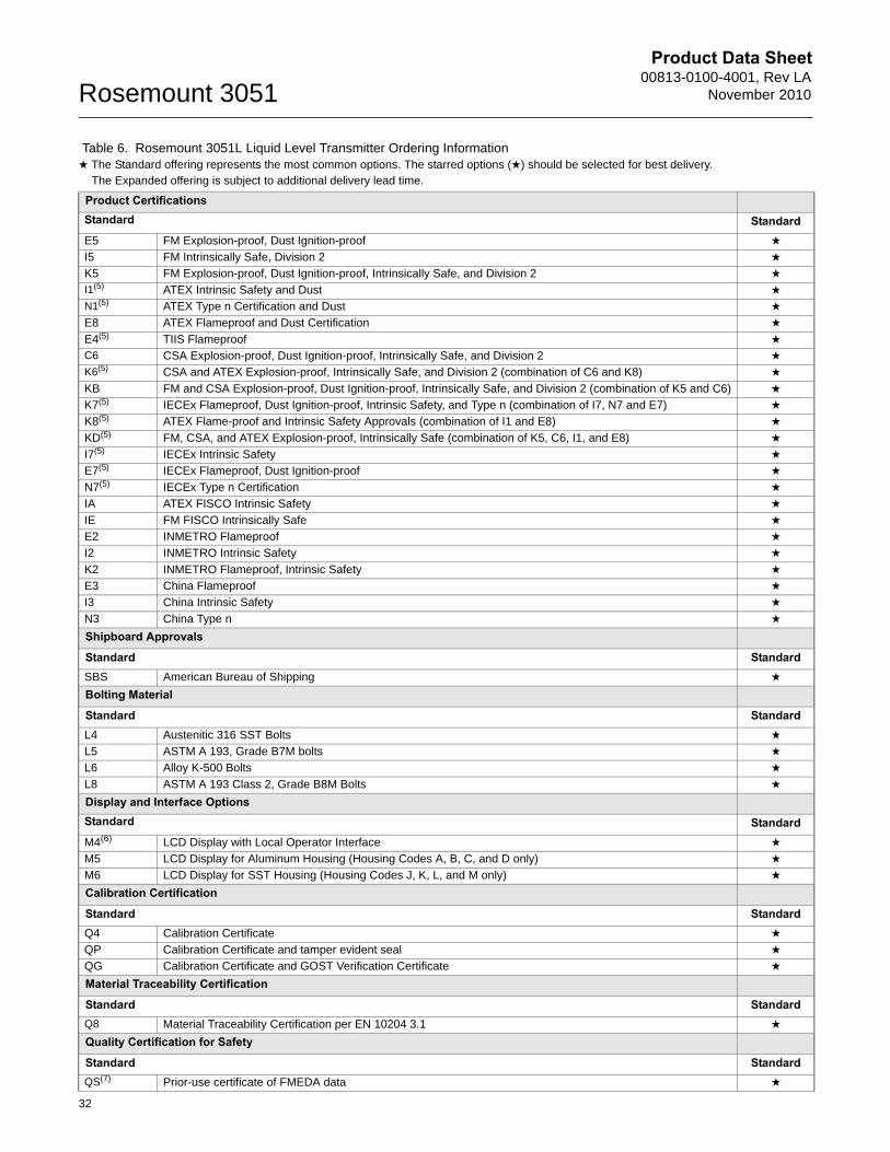
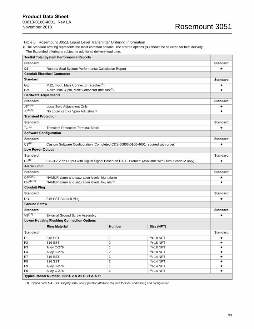
Table 6. Rosemount 3051L Liquid Level Transmitter Ordering Information★ The Standard offering represents the most common options. The starred options (★) should be selected for best delivery.__The Expanded offering is subject to additional delivery lead time.
Model Transmitter Type3051L Liquid Level Transmitter
Pressure RangeStandard Standard2 –250 to 250 inH2O (–0,6 to 0,6 bar) ★
3 –1000 to 1000 inH2O (–2,5 to 2,5 bar) ★
4 –300 to 300 psi (–20,7 to 20,7 bar) ★
Transmitter OutputStandard StandardA 4–20 mA with Digital Signal Based on HART Protocol ★
F FOUNDATION fieldbus Protocol ★
W(1) Profibus PA Protocol ★
Expanded
M Low-Power 1–5 V dc with Digital Signal Based on HART Protocol (See Option Code C2 for 0.8–3.2 V dc Output)
Process Connection Size, Material, Extension length (High Side)Standard Standard
Code Process Connection Size Material Extension Length ★
G0(2) 2-in./DN 50 316L SST Flush Mount Only ★
H0(2) 2-in./DN 50 Alloy C-276 Flush Mount Only ★
J0 2-in./DN 50 Tantalum Flush Mount Only ★
A0(2) 3-in./DN 80 316L SST Flush Mount ★
A2(2) 3-in./DN 80 316L SST 2-in./50 mm ★
A4(2) 3-in./DN 80 316L SST 4-in./100 mm ★
A6(2) 3-in./DN 80 316L SST 6-in./150 mm ★
B0(2) 4-in./DN 100 316L SST Flush Mount ★
B2(2) 4-in./DN 100 316L SST 2-in./50 mm ★
B4(2) 4-in./DN 100 316L SST 4-in./100 mm ★
3051L Liquid Level Transmitter
29
Product Data Sheet00813-0100-4001, Rev LA
November 2010Rosemount 3051
B6(2) 4-in./DN 100 316L SST 6-in./150 mm ★
C0(2) 3-in./DN 80 Alloy C-276 Flush Mount ★
C2(2) 3-in./DN 80 Alloy C-276 2-in./50 mm ★
C4(2) 3-in./DN 80 Alloy C-276 4-in./100 mm ★
C6(2) 3-in./DN 80 Alloy C-276 6-in./150 mm ★
D0(2) 4-in./DN 100 Alloy C-276 Flush Mount ★
D2(2) 4-in./DN 100 Alloy C-276 2-in./50 mm ★
D4(2) 4-in./DN 100 Alloy C-276 4-in./100 mm ★
D6(2) 4-in./DN 100 Alloy C-276 6-in./150 mm ★
E0 3-in./DN 80 Tantalum Flush Mount Only ★
F0 4-in./DN 100 Tantalum Flush Mount Only ★
Mounting Flange Size, Rating, Material (High Side)Size Rating Material
Standard StandardM 2-in. ANSI/ASME B16.5 Class 150 CS ★
A 3-in. ANSI/ASME B16.5 Class 150 CS ★
B 4-in. ANSI/ASME B16.5 Class 150 CS ★
N 2-in. ANSI/ASME B16.5 Class 300 CS ★
C 3-in. ANSI/ASME B16.5 Class 300 CS ★
D 4-in. ANSI/ASME B16.5 Class 300 CS ★
P 2-in. ANSI/ASME B16.5 Class 600 CS ★
E 3-in. ANSI/ASME B16.5 Class 600 CS ★
X(2) 2-in. ANSI/ASME B16.5 Class 150 SST ★
F(2) 3-in. ANSI/ASME B16.5 Class 150 SST ★
G(2) 4-in. ANSI/ASME B16.5 Class 150 SST ★
Y(2) 2-in. ANSI/ASME B16.5 Class 300 SST ★
H(2) 3-in. ANSI/ASME B16.5 Class 300 SST ★
J(2) 4-in. ANSI/ASME B16.5 Class 300 SST ★
Z(2) 2-in. ANSI/ASME B16.5 Class 600 SST ★
L(2) 3-in. ANSI/ASME B16.5 Class 600 SST ★
Q DN 50 PN 10-40 per EN 1092-1 CS ★
R DN 80 PN 40 per EN 1092-1 CS ★
S DN 100 PN 40 per EN 1092-1 CS ★
V DN 100 PN 10/16 per EN 1092-1 CS ★
K(2) DN 50 PN 10-40 per EN 1092-1 SST ★
T(2) DN 80 PN 40 per EN 1092-1 SST ★
U(2) DN 100 PN 40 per EN 1092-1 SST ★
W(2) DN 100 PN 10/16 per EN 1092-1 SST ★
7(2) 4 in. ANSI/ASME B16.5 Class 600 SST ★
Expanded
1 — 10K per JIS B2238 CS
2 — 20K per JIS B2238 CS
3 — 40K per JIS B2238 CS
4(2) — 10K per JIS B2238 316 SST
5(2) — 20K per JIS B2238 316 SST
6(2) — 40K per JIS B2238 316 SST
Table 6. Rosemount 3051L Liquid Level Transmitter Ordering Information★ The Standard offering represents the most common options. The starred options (★) should be selected for best delivery.__The Expanded offering is subject to additional delivery lead time.
30
Product Data Sheet00813-0100-4001, Rev LANovember 2010 Rosemount 3051
Seal Fill Fluid (High Side) Specific Gravity Temperature Limits (Ambient Temperature of 70° F (21° C))Standard StandardA Syltherm XLT 0.85 -102 to 293 °F (-75 to 145 °C) ★
C Silicone 704 1.07 32 to 401 °F (0 to 205 °C) ★
D Silicone 200 0.93 -49 to 401 °F (-45 to 205 °C) ★
H Inert (Halocarbon) 1.85 -49 to 320 °F (-45 to 160 °C) ★
G Glycerine and Water 1.13 5 to 203 °F (-15 to 95 °C) ★
N Neobee M-20 0.92 5 to 401 °F (-15 to 205 °C) ★
P Propylene Glycol and Water
1.02 5 to 203 F (-15 to 95 °C) ★
Low Pressure Side
Configuration Flange Adapter Diaphragm Material Sensor Fill FluidStandard Standard11(2) Gage SST 316L SST Silicone ★
21(2) Differential SST 316L SST Silicone ★
22(2) Differential SST Alloy C-276 Silicone ★
2A(2) Differential SST 316L SST Inert (Halocarbon) ★
2B(2) Differential SST Alloy C-276 Inert (Halocarbon) ★
31(2) Tuned-System Assembly with Remote Seal
None 316L SST Silicone (Requires Option Code S1)
★
O-ringStandard StandardA Glass-filled PTFE ★
Housing Material Conduit Entry SizeStandard StandardA Aluminum ½–14 NPT ★
B Aluminum M20 × 1.5 ★
J SST ½–14 NPT ★
K SST M20 × 1.5 ★
Expanded
D Aluminum G½
M SST G½
Options (Include with selected model number)
PlantWeb Control FunctionalityStandard StandardA01(3) FOUNDATION fieldbus Advanced Control Function Block Suite ★
PlantWeb Diagnostic FunctionalityStandard StandardD01(3) FOUNDATION fieldbus Diagnostics Suite ★
Seal AssembliesStandard StandardS1(4) Assembled to One Rosemount 1199 Seal (Requires 1199M) ★
Table 6. Rosemount 3051L Liquid Level Transmitter Ordering Information★ The Standard offering represents the most common options. The starred options (★) should be selected for best delivery.__The Expanded offering is subject to additional delivery lead time.
31
Product Data Sheet00813-0100-4001, Rev LA
November 2010Rosemount 3051
Product CertificationsStandard StandardE5 FM Explosion-proof, Dust Ignition-proof ★
I5 FM Intrinsically Safe, Division 2 ★
K5 FM Explosion-proof, Dust Ignition-proof, Intrinsically Safe, and Division 2 ★
I1(5) ATEX Intrinsic Safety and Dust ★
N1(5) ATEX Type n Certification and Dust ★
E8 ATEX Flameproof and Dust Certification ★
E4(5) TIIS Flameproof ★
C6 CSA Explosion-proof, Dust Ignition-proof, Intrinsically Safe, and Division 2 ★
K6(5) CSA and ATEX Explosion-proof, Intrinsically Safe, and Division 2 (combination of C6 and K8) ★
KB FM and CSA Explosion-proof, Dust Ignition-proof, Intrinsically Safe, and Division 2 (combination of K5 and C6) ★
K7(5) IECEx Flameproof, Dust Ignition-proof, Intrinsic Safety, and Type n (combination of I7, N7 and E7) ★
K8(5) ATEX Flame-proof and Intrinsic Safety Approvals (combination of I1 and E8) ★
KD(5) FM, CSA, and ATEX Explosion-proof, Intrinsically Safe (combination of K5, C6, I1, and E8) ★
I7(5) IECEx Intrinsic Safety ★
E7(5) IECEx Flameproof, Dust Ignition-proof ★
N7(5) IECEx Type n Certification ★
IA ATEX FISCO Intrinsic Safety ★
IE FM FISCO Intrinsically Safe ★
E2 INMETRO Flameproof ★
I2 INMETRO Intrinsic Safety ★
K2 INMETRO Flameproof, Intrinsic Safety ★
E3 China Flameproof ★
I3 China Intrinsic Safety ★
N3 China Type n ★
Shipboard Approvals
Standard StandardSBS American Bureau of Shipping ★
Bolting Material
Standard StandardL4 Austenitic 316 SST Bolts ★
L5 ASTM A 193, Grade B7M bolts ★
L6 Alloy K-500 Bolts ★
L8 ASTM A 193 Class 2, Grade B8M Bolts ★
Display and Interface OptionsStandard StandardM4(6) LCD Display with Local Operator Interface ★
M5 LCD Display for Aluminum Housing (Housing Codes A, B, C, and D only) ★
M6 LCD Display for SST Housing (Housing Codes J, K, L, and M only) ★
Calibration Certification
Standard StandardQ4 Calibration Certificate ★
QP Calibration Certificate and tamper evident seal ★
QG Calibration Certificate and GOST Verification Certificate ★
Material Traceability Certification
Standard StandardQ8 Material Traceability Certification per EN 10204 3.1 ★
Quality Certification for Safety
Standard StandardQS(7) Prior-use certificate of FMEDA data ★
Table 6. Rosemount 3051L Liquid Level Transmitter Ordering Information★ The Standard offering represents the most common options. The starred options (★) should be selected for best delivery.__The Expanded offering is subject to additional delivery lead time.
32
Product Data Sheet00813-0100-4001, Rev LANovember 2010 Rosemount 3051
Toolkit Total System Performance Reports
Standard StandardQZ Remote Seal System Performance Calculation Report ★
Conduit Electrical ConnectorStandard StandardGE M12, 4-pin, Male Connector (eurofast®) ★
GM A size Mini, 4-pin, Male Connector (minifast®) ★
Hardware Adjustments
Standard StandardJ1(8)(9) Local Zero Adjustment Only ★
J3(8)(9) No Local Zero or Span Adjustment ★
Transient Protection
Standard StandardT1(10) Transient Protection Terminal Block ★
Software Configuration
Standard StandardC1(8) Custom Software Configuration (Completed CDS 00806-0100-4001 required with order) ★
Low Power Output
Standard StandardC2(8) 0.8–3.2 V dc Output with Digital Signal Based on HART Protocol (Available with Output code M only) ★
Alarm Limit
Standard StandardC4(8)(11) NAMUR alarm and saturation levels, high alarm ★
CN(8)(11) NAMUR alarm and saturation levels, low alarm ★
Conduit Plug
Standard StandardDO 316 SST Conduit Plug ★
Ground Screw
Standard StandardV5(12) External Ground Screw Assembly ★
Lower Housing Flushing Connection Options
Ring Material Number Size (NPT)
Standard StandardF1 316 SST 1 1/4-18 NPT ★
F2 316 SST 2 1/4-18 NPT ★
F3 Alloy C-276 1 1/4-18 NPT ★
F4 Alloy C-276 2 1/4-18 NPT ★
F7 316 SST 1 1/2-14 NPT ★
F8 316 SST 2 1/2-14 NPT ★
F9 Alloy C-276 1 1/2-14 NPT ★
F0 Alloy C-276 2 1/2-14 NPT ★
Typical Model Number: 3051L 2 A A0 D 21 A A F1
(1) Option code M4 - LCD Display with Local Operator Interface required for local addressing and configuration.
Table 6. Rosemount 3051L Liquid Level Transmitter Ordering Information★ The Standard offering represents the most common options. The starred options (★) should be selected for best delivery.__The Expanded offering is subject to additional delivery lead time.
33
Product Data Sheet00813-0100-4001, Rev LA
November 2010Rosemount 3051
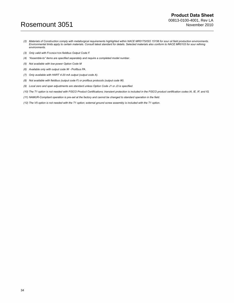
(2) Materials of Construction comply with metallurgical requirements highlighted within NACE MR0175/ISO 15156 for sour oil field production environments. Environmental limits apply to certain materials. Consult latest standard for details. Selected materials also conform to NACE MR0103 for sour refining environments.
(3) Only valid with FOUNDATION fieldbus Output Code F.
(4) “Assemble-to” items are specified separately and require a completed model number.
(5) Not available with low-power Option Code M
(6) Available only with output code W - Profibus PA.
(7) Only available with HART 4-20 mA output (output code A).
(8) Not available with fieldbus (output code F) or profibus protocols (output code W).
(9) Local zero and span adjustments are standard unless Option Code J1 or J3 is specified.
(10) The T1 option is not needed with FISCO Product Certifications; transient protection is included in the FISCO product certification codes IA, IE, IF, and IG.
(11) NAMUR-Compliant operation is pre-set at the factory and cannot be changed to standard operation in the field.
(12) The V5 option is not needed with the T1 option; external ground screw assembly is included with the T1 option.
34
Product Data Sheet00813-0100-4001, Rev LANovember 2010 Rosemount 3051
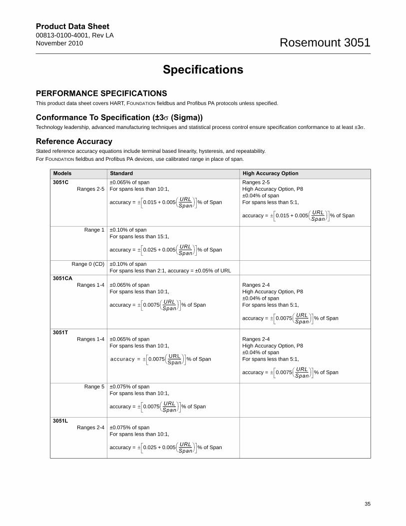
Specifications
PERFORMANCE SPECIFICATIONSThis product data sheet covers HART, FOUNDATION fieldbus and Profibus PA protocols unless specified.
Conformance To Specification (±3 (Sigma))Technology leadership, advanced manufacturing techniques and statistical process control ensure specification conformance to at least ±3.
Reference AccuracyStated reference accuracy equations include terminal based linearity, hysteresis, and repeatability.
For FOUNDATION fieldbus and Profibus PA devices, use calibrated range in place of span.
Models Standard High Accuracy Option3051C
Ranges 2-5±0.065% of spanFor spans less than 10:1,
accuracy =
Ranges 2-5High Accuracy Option, P8±0.04% of spanFor spans less than 5:1,
accuracy =
Range 1 ±0.10% of spanFor spans less than 15:1,
accuracy =
Range 0 (CD) ±0.10% of spanFor spans less than 2:1, accuracy = ±0.05% of URL
3051CARanges 1-4 ±0.065% of span
For spans less than 10:1,
accuracy =
Ranges 2-4 High Accuracy Option, P8±0.04% of spanFor spans less than 5:1,
accuracy =
3051TRanges 1-4 ±0.065% of span
For spans less than 10:1,Ranges 2-4 High Accuracy Option, P8±0.04% of spanFor spans less than 5:1,
accuracy =
Range 5 ±0.075% of spanFor spans less than 10:1,
accuracy =
3051LRanges 2-4 ±0.075% of span
For spans less than 10:1,
accuracy =
0.015 0.005+URLSpan--------------- % of Span
0.015 0.005+URLSpan--------------- % of Span
0.025 0.005+URLSpan--------------- % of Span
0.0075URLSpan--------------- % of Span
0.0075URLSpan--------------- % of Span
accuracy 0.0075URLSpan--------------- % of Span=
0.0075URLSpan--------------- % of Span
0.0075URLSpan--------------- % of Span
0.025 0.005+URLSpan--------------- % of Span
35
Product Data Sheet00813-0100-4001, Rev LA
November 2010Rosemount 3051
36
Total PerformanceTotal Performance is based on combined errors of reference accuracy, ambient temperature effect, and static pressure effect.
Long Term Stability
Dynamic Performance
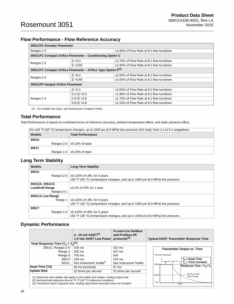
Flow Performance - Flow Reference Accuracy3051CFA Annubar Flowmeter
Ranges 2-3 ±1.60% of Flow Rate at 8:1 flow turndown
3051CFC Compact Orifice Flowmeter – Conditioning Option C
Ranges 2-3=0.4 ±1.75% of Flow Rate at 8:1 flow turndown
=0.65 ±1.95% of Flow Rate at 8:1 flow turndown
3051CFC Compact Orifice Flowmeter – Orifice Type Option P(1)
Ranges 2-3=0.4 ±2.00% of Flow Rate at 8:1 flow turndown
=0.65 ±2.00% of Flow Rate at 8:1 flow turndown
3051CFP Integral Orifice Flowmeter
<0.1 ±3.00% of Flow Rate at 8:1 flow turndown
Ranges 2-3
0.1< <0.2 ±1.95% of Flow Rate at 8:1 flow turndown
0.2< <0.6 ±1.75% of Flow Rate at 8:1 flow turndown
0.6< <0.8 ±2.15% of Flow Rate at 8:1 flow turndown
(1) For smaller line sizes, see Rosemount Compact Orifice
For ±50 °F (28 °C) temperature changes, up to 1000 psi (6,9 MPa) line pressure (CD only), from 1:1 to 5:1 rangedown.
Models Total Performance
3051CRanges 2-5 ±0.15% of span
3051TRanges 1-4 ±0.15% of span
Models Long Term Stability
3051CRanges 2-5 ±0.125% of URL for 5 years
±50 °F (28 °C) temperature changes, and up to 1000 psi (6.9 MPa) line pressure.
3051CD, 3051CG Low/Draft Range
Ranges 0-1±0.2% of URL for 1 year
3051CA Low RangeRange 1 ±0.125% of URL for 5 years
±50 °F (28 °C) temperature changes, and up to 1000 psi (6.9 MPa) line pressure.
3051TRanges 1-5 ±0.125% of URL for 5 years
±50 °F (28 °C) temperature changes, and up to 1000 psi (6.9 MPa) line pressure.
4 - 20 mA HART(1)
1-5 Vdc HART Low Power
FOUNDATION fieldbus and Profibus PA protocols(3) Typical HART Transmitter Response Time
Total Response Time (Td + Tc)(2):3051C, Ranges 2-5:
Range 1:Range 0:
3051T:3051L:
100 ms 255 ms700 ms100 ms See Instrument Toolkit®
152 ms307 msN/A152 msSee Instrument Toolkit
Dead Time (Td) 45 ms (nominal) 97 msUpdate Rate 22 times per second 22 times per second
(1) Dead time and update rate apply to all models and ranges; analog output only(2) Nominal total response time at 75 °F (24 °C) reference conditions. (3) Transducer block response time, Analog Input block execution time not included.
TcTd
Td = Dead TimeTc = Time Constant
Pressure Released
Response Time = Td+Tc
63.2% of TotalStep Change
Time0%
100%
36.8%
Transmitter Output vs. Time

Product Data Sheet00813-0100-4001, Rev LANovember 2010 Rosemount 3051
Line Pressure Effect per 1000 psi (6,9 MPa)
Ambient Temperature Effect per 50°F (28°C)
Mounting Position Effects
Vibration EffectLess than ±0.1% of URL when tested per the requirements of IEC60770-1 field or pipeline with high vibration level (10-60 Hz 0.21 mm displacement peak amplitude / 60-2000 Hz 3g).
Power Supply EffectLess than ±0.005% of calibrated span per volt.
Electromagnetic Compatibility (EMC)Meets all relevant requirements of EN 61326 and Namur NE-21.
Transient Protection (Option Code T1)Meets IEEE C62.41, Category Location B
6 kV crest (0.5 s - 100 kHz)3 kV crest (8 × 20 microseconds)6 kV crest (1.2 × 50 microseconds)
For line pressures above 2000 psi (13,7 MPa) and Ranges 4-5, see user manual (Document number 00809-0100-4001 for HART, 00809-0100-4774 for FOUNDATION fieldbus, and 00809-0100-4797 for Profibus PA).
Models Line Pressure Effect3051CD, 3051CF Zero Error(1)
(1) Can be calibrated out at line pressure.
Ranges 2-3 ±0.05% of URL/1000 psi (68,9 bar) for line pressures from 0 to 2000 psi (0 to 13,7 MPa)
Range 1 ±0.25% of URL/1000 psi (68,9 bar)
Range 0 ±0.125% of URL/100 psi (6,89 bar)
Span Error
Ranges 2-3 ±0.1% of reading/1000 psi (68,9 bar)
Range 1 ±0.4% of reading/1000 psi (68,9 bar)
Range 0 ±0.15% of reading/100 psi (6,89 bar)
Models Ambient Temperature Effect3051C
Ranges 2-5 ±(0.0125% URL + 0.0625% span) from 1:1 to 5:1±(0.025% URL + 0.125% span) from 5:1 to 100:1
Range 1 ±(0.1% URL + 0.25% span) from 1:1 to 30:1
Range 0 ±(0.25% URL + 0.05% span) from 1:1 to 30:1
3051CARanges 1-4 ±(0.025% URL + 0.125% span) from 1:1 to 30:1
±(0.035% URL + 0.125% span) from 30:1 to 100:1
3051TRange 2-4 ±(0.025% URL + 0.125% span) from 1:1 to 30:1
±(0.035% URL + 0.125% span) from 30:1 to 100:1
Range 1 ±(0.025% URL + 0.125% span) from 1:1 to 10:1±(0.05% URL + 0.125% span) from 10:1 to 100:1
Range 5 ±(0.1% URL + 0.15% span)
3051L See Instrument Toolkit software.
Models Mounting Position Effects3051C Zero shifts up to ±1.25 inH2O (3,11 mbar), which can be calibrated out. No span effect.
3051CA, 3051T Zero shifts up to 2.5 inH2O (6,22 mbar), which can be calibrated out. No span effect.
3051L With liquid level diaphragm in vertical plane, zero shift of up to 1 inH2O (2,49 mbar). With diaphragm in horizontal plane, zero shift of up to 5 inH2O (12,43 mbar) plus extension length on extended units. All zero shifts can be calibrated out. No span effect.
37
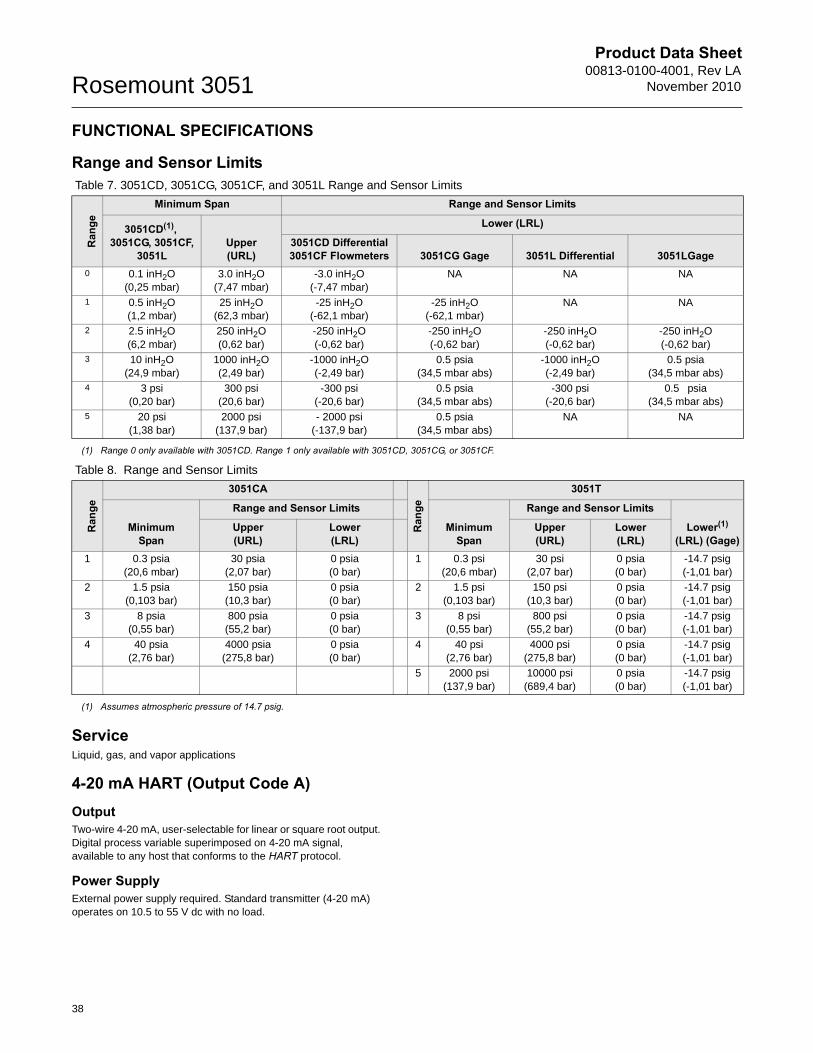
Product Data Sheet00813-0100-4001, Rev LA
November 2010Rosemount 3051
38
FUNCTIONAL SPECIFICATIONS
Range and Sensor Limits
ServiceLiquid, gas, and vapor applications
4-20 mA HART (Output Code A)OutputTwo-wire 4-20 mA, user-selectable for linear or square root output. Digital process variable superimposed on 4-20 mA signal, available to any host that conforms to the HART protocol.
Power SupplyExternal power supply required. Standard transmitter (4-20 mA) operates on 10.5 to 55 V dc with no load.
Table 7. 3051CD, 3051CG, 3051CF, and 3051L Range and Sensor Limits
Ran
ge
Minimum Span Range and Sensor Limits
3051CD(1), 3051CG, 3051CF,
3051LUpper (URL)
Lower (LRL)
3051CD Differential3051CF Flowmeters 3051CG Gage 3051L Differential 3051LGage
0 0.1 inH2O(0,25 mbar)
3.0 inH2O(7,47 mbar)
-3.0 inH2O(-7,47 mbar)
NA NA NA
1 0.5 inH2O(1,2 mbar)
25 inH2O(62,3 mbar)
-25 inH2O(-62,1 mbar)
-25 inH2O(-62,1 mbar)
NA NA
2 2.5 inH2O (6,2 mbar)
250 inH2O(0,62 bar)
-250 inH2O(-0,62 bar)
-250 inH2O(-0,62 bar)
-250 inH2O(-0,62 bar)
-250 inH2O(-0,62 bar)
3 10 inH2O (24,9 mbar)
1000 inH2O (2,49 bar)
-1000 inH2O (-2,49 bar)
0.5 psia
(34,5 mbar abs)-1000 inH2O (-2,49 bar)
0.5 psia(34,5 mbar abs)
4 3 psi (0,20 bar)
300 psi (20,6 bar)
-300 psi(-20,6 bar)
0.5 psia
(34,5 mbar abs)-300 psi
(-20,6 bar)0.5 psia
(34,5 mbar abs)5 20 psi
(1,38 bar)2000 psi
(137,9 bar)- 2000 psi
(-137,9 bar)0.5 psia
(34,5 mbar abs)NA NA
(1) Range 0 only available with 3051CD. Range 1 only available with 3051CD, 3051CG, or 3051CF.
Table 8. Range and Sensor Limits
Ran
ge
3051CA
Ran
ge
3051T
Minimum Span
Range and Sensor Limits
Minimum Span
Range and Sensor Limits
Lower(1)
(LRL) (Gage)Upper(URL)
Lower (LRL)
Upper(URL)
Lower (LRL)
1 0.3 psia(20,6 mbar)
30 psia(2,07 bar)
0 psia (0 bar)
1 0.3 psi(20,6 mbar)
30 psi(2,07 bar)
0 psia(0 bar)
-14.7 psig(-1,01 bar)
2 1.5 psia(0,103 bar)
150 psia(10,3 bar)
0 psia (0 bar)
2 1.5 psi(0,103 bar)
150 psi(10,3 bar)
0 psia(0 bar)
-14.7 psig(-1,01 bar)
3 8 psia(0,55 bar)
800 psia(55,2 bar)
0 psia (0 bar)
3 8 psi(0,55 bar)
800 psi(55,2 bar)
0 psia(0 bar)
-14.7 psig(-1,01 bar)
4 40 psia(2,76 bar)
4000 psia(275,8 bar)
0 psia (0 bar)
4 40 psi(2,76 bar)
4000 psi(275,8 bar)
0 psia(0 bar)
-14.7 psig(-1,01 bar)
5 2000 psi(137,9 bar)
10000 psi(689,4 bar)
0 psia(0 bar)
-14.7 psig(-1,01 bar)
(1) Assumes atmospheric pressure of 14.7 psig.
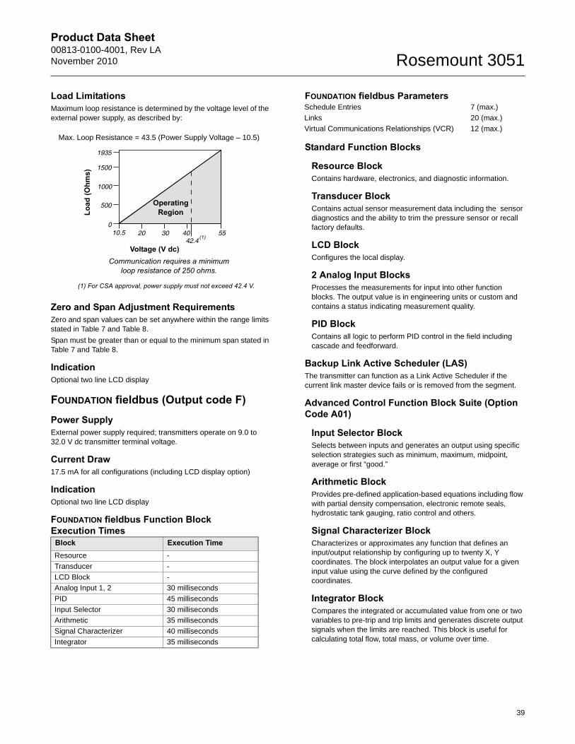
Product Data Sheet00813-0100-4001, Rev LANovember 2010 Rosemount 3051
39
Load Limitations Maximum loop resistance is determined by the voltage level of the external power supply, as described by:
Zero and Span Adjustment RequirementsZero and span values can be set anywhere within the range limits stated in Table 7 and Table 8.
Span must be greater than or equal to the minimum span stated in Table 7 and Table 8.
IndicationOptional two line LCD display
FOUNDATION fieldbus (Output code F) Power SupplyExternal power supply required; transmitters operate on 9.0 to 32.0 V dc transmitter terminal voltage.
Current Draw17.5 mA for all configurations (including LCD display option)
IndicationOptional two line LCD display
FOUNDATION fieldbus Function Block Execution Times
FOUNDATION fieldbus Parameters
Standard Function Blocks
Resource BlockContains hardware, electronics, and diagnostic information.
Transducer BlockContains actual sensor measurement data including the sensor diagnostics and the ability to trim the pressure sensor or recall factory defaults.
LCD BlockConfigures the local display.
2 Analog Input BlocksProcesses the measurements for input into other function blocks. The output value is in engineering units or custom and contains a status indicating measurement quality.
PID Block Contains all logic to perform PID control in the field including cascade and feedforward.
Backup Link Active Scheduler (LAS)The transmitter can function as a Link Active Scheduler if the current link master device fails or is removed from the segment.
Advanced Control Function Block Suite (Option Code A01)
Input Selector BlockSelects between inputs and generates an output using specific selection strategies such as minimum, maximum, midpoint, average or first “good.”
Arithmetic BlockProvides pre-defined application-based equations including flow with partial density compensation, electronic remote seals, hydrostatic tank gauging, ratio control and others.
Signal Characterizer BlockCharacterizes or approximates any function that defines an input/output relationship by configuring up to twenty X, Y coordinates. The block interpolates an output value for a given input value using the curve defined by the configured coordinates.
Integrator BlockCompares the integrated or accumulated value from one or two variables to pre-trip and trip limits and generates discrete output signals when the limits are reached. This block is useful for calculating total flow, total mass, or volume over time.
Block Execution TimeResource -
Transducer -
LCD Block -
Analog Input 1, 2 30 milliseconds
PID 45 milliseconds
Input Selector 30 milliseconds
Arithmetic 35 milliseconds
Signal Characterizer 40 milliseconds
Integrator 35 milliseconds
Voltage (V dc)
Load
(Ohm
s)
Communication requires a minimum loop resistance of 250 ohms.
(1) For CSA approval, power supply must not exceed 42.4 V.
Max. Loop Resistance = 43.5 (Power Supply Voltage – 10.5)
OperatingRegion
Schedule Entries 7 (max.)
Links 20 (max.)
Virtual Communications Relationships (VCR) 12 (max.)
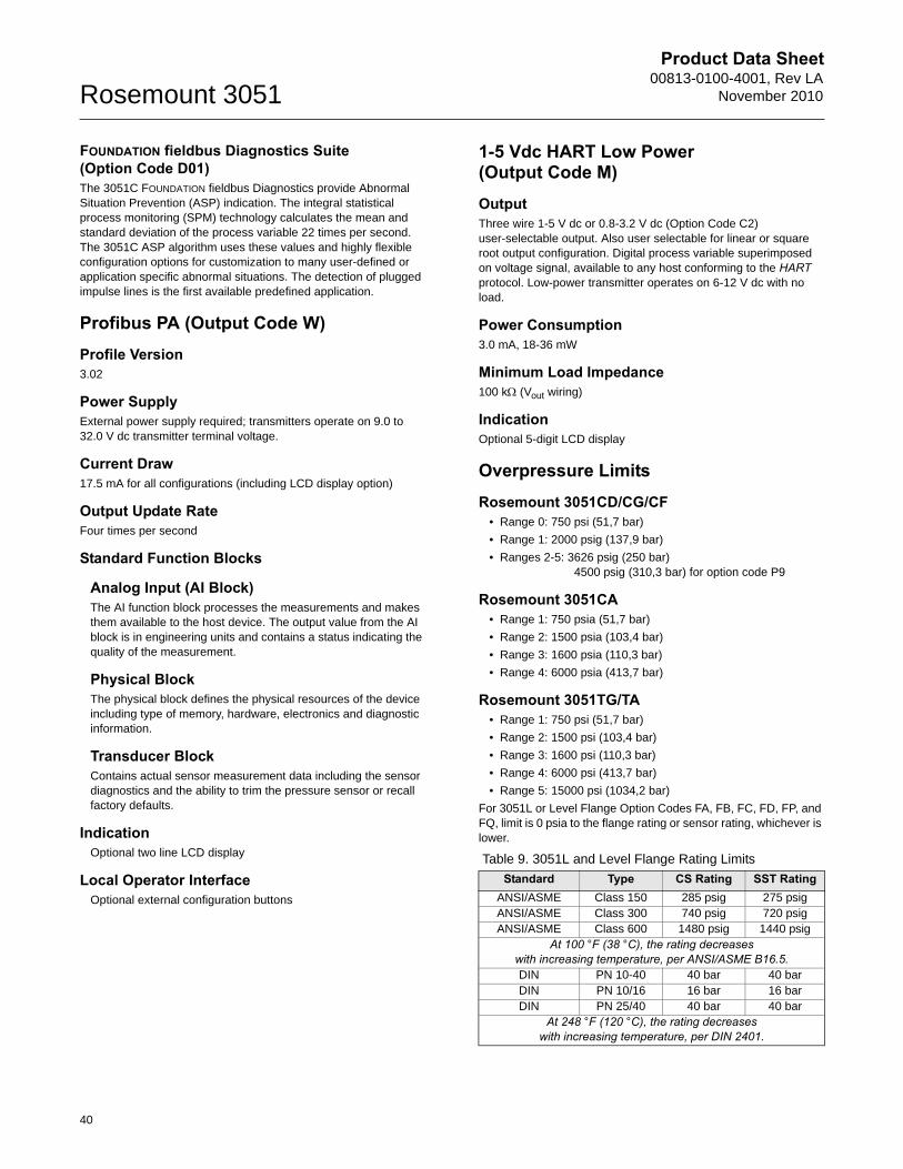
Product Data Sheet00813-0100-4001, Rev LA
November 2010Rosemount 3051
FOUNDATION fieldbus Diagnostics Suite (Option Code D01)The 3051C FOUNDATION fieldbus Diagnostics provide Abnormal Situation Prevention (ASP) indication. The integral statistical process monitoring (SPM) technology calculates the mean and standard deviation of the process variable 22 times per second. The 3051C ASP algorithm uses these values and highly flexible configuration options for customization to many user-defined or application specific abnormal situations. The detection of plugged impulse lines is the first available predefined application.
Profibus PA (Output Code W)Profile Version3.02
Power SupplyExternal power supply required; transmitters operate on 9.0 to 32.0 V dc transmitter terminal voltage.
Current Draw17.5 mA for all configurations (including LCD display option)
Output Update RateFour times per second
Standard Function Blocks
Analog Input (AI Block)The AI function block processes the measurements and makes them available to the host device. The output value from the AI block is in engineering units and contains a status indicating the quality of the measurement.
Physical BlockThe physical block defines the physical resources of the device including type of memory, hardware, electronics and diagnostic information.
Transducer BlockContains actual sensor measurement data including the sensor diagnostics and the ability to trim the pressure sensor or recall factory defaults.
IndicationOptional two line LCD display
Local Operator InterfaceOptional external configuration buttons
1-5 Vdc HART Low Power (Output Code M)OutputThree wire 1-5 V dc or 0.8-3.2 V dc (Option Code C2) user-selectable output. Also user selectable for linear or square root output configuration. Digital process variable superimposed on voltage signal, available to any host conforming to the HART protocol. Low-power transmitter operates on 6-12 V dc with no load.
Power Consumption3.0 mA, 18-36 mW
Minimum Load Impedance100 k (Vout wiring)
IndicationOptional 5-digit LCD display
Overpressure LimitsRosemount 3051CD/CG/CF
• Range 0: 750 psi (51,7 bar)
• Range 1: 2000 psig (137,9 bar)
• Ranges 2-5: 3626 psig (250 bar) 4500 psig (310,3 bar) for option code P9
Rosemount 3051CA• Range 1: 750 psia (51,7 bar)
• Range 2: 1500 psia (103,4 bar)
• Range 3: 1600 psia (110,3 bar)
• Range 4: 6000 psia (413,7 bar)
Rosemount 3051TG/TA• Range 1: 750 psi (51,7 bar)
• Range 2: 1500 psi (103,4 bar)
• Range 3: 1600 psi (110,3 bar)
• Range 4: 6000 psi (413,7 bar)
• Range 5: 15000 psi (1034,2 bar)
For 3051L or Level Flange Option Codes FA, FB, FC, FD, FP, and FQ, limit is 0 psia to the flange rating or sensor rating, whichever is lower.
Table 9. 3051L and Level Flange Rating Limits
Standard Type CS Rating SST RatingANSI/ASME Class 150 285 psig 275 psigANSI/ASME Class 300 740 psig 720 psigANSI/ASME Class 600 1480 psig 1440 psig
At 100 °F (38 °C), the rating decreaseswith increasing temperature, per ANSI/ASME B16.5.DIN PN 10-40 40 bar 40 barDIN PN 10/16 16 bar 16 barDIN PN 25/40 40 bar 40 bar
At 248 °F (120 °C), the rating decreases with increasing temperature, per DIN 2401.
40
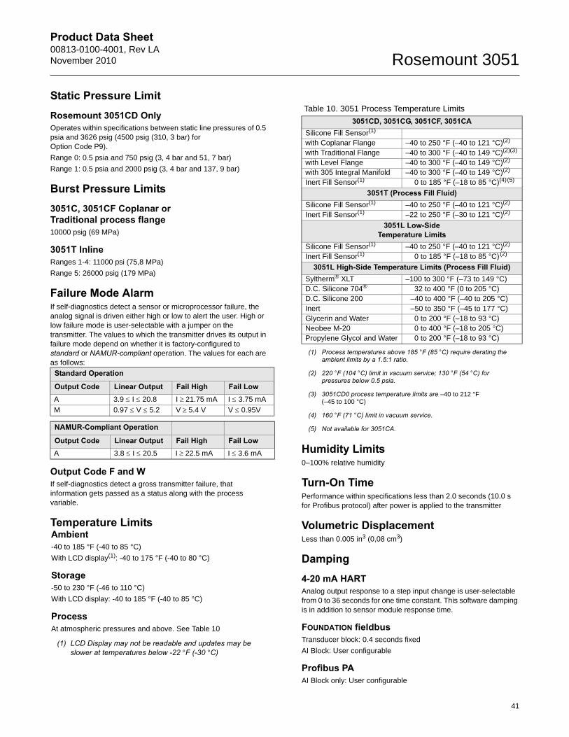
Product Data Sheet00813-0100-4001, Rev LANovember 2010 Rosemount 3051
Static Pressure LimitRosemount 3051CD OnlyOperates within specifications between static line pressures of 0.5 psia and 3626 psig (4500 psig (310, 3 bar) for Option Code P9).
Range 0: 0.5 psia and 750 psig (3, 4 bar and 51, 7 bar)
Range 1: 0.5 psia and 2000 psig (3, 4 bar and 137, 9 bar)
Burst Pressure Limits3051C, 3051CF Coplanar or Traditional process flange10000 psig (69 MPa)
3051T InlineRanges 1-4: 11000 psi (75,8 MPa)
Range 5: 26000 psig (179 MPa)
Failure Mode AlarmIf self-diagnostics detect a sensor or microprocessor failure, the analog signal is driven either high or low to alert the user. High or low failure mode is user-selectable with a jumper on the transmitter. The values to which the transmitter drives its output in failure mode depend on whether it is factory-configured to standard or NAMUR-compliant operation. The values for each are as follows:
Output Code F and WIf self-diagnostics detect a gross transmitter failure, that information gets passed as a status along with the process variable.
Temperature Limits
Humidity Limits0–100% relative humidity
Turn-On TimePerformance within specifications less than 2.0 seconds (10.0 s for Profibus protocol) after power is applied to the transmitter
Volumetric DisplacementLess than 0.005 in3 (0,08 cm3)
Damping4-20 mA HARTAnalog output response to a step input change is user-selectable from 0 to 36 seconds for one time constant. This software damping is in addition to sensor module response time.
FOUNDATION fieldbusTransducer block: 0.4 seconds fixed
AI Block: User configurable
Profibus PAAI Block only: User configurable
Standard Operation
Output Code Linear Output Fail High Fail LowA 3.9 I 20.8 I 21.75 mA I 3.75 mA
M 0.97 V 5.2 V 5.4 V V 0.95V
NAMUR-Compliant Operation
Output Code Linear Output Fail High Fail LowA 3.8 I 20.5 I 22.5 mA I 3.6 mA
Ambient-40 to 185 °F (-40 to 85 °C)
With LCD display(1): -40 to 175 °F (-40 to 80 °C)
Storage-50 to 230 °F (-46 to 110 °C)
With LCD display: -40 to 185 °F (-40 to 85 °C)
ProcessAt atmospheric pressures and above. See Table 10
(1) LCD Display may not be readable and updates may be slower at temperatures below -22 °F (-30 °C)
Table 10. 3051 Process Temperature Limits
3051CD, 3051CG, 3051CF, 3051CASilicone Fill Sensor(1)
(1) Process temperatures above 185 °F (85 °C) require derating the ambient limits by a 1.5:1 ratio.
with Coplanar Flange –40 to 250 °F (–40 to 121 °C)(2)
(2) 220 °F (104 °C) limit in vacuum service; 130 °F (54 °C) for pressures below 0.5 psia.
with Traditional Flange –40 to 300 °F (–40 to 149 °C)(2)(3)
(3) 3051CD0 process temperature limits are –40 to 212 °F (–45 to 100 °C)
with Level Flange –40 to 300 °F (–40 to 149 °C)(2)
with 305 Integral Manifold –40 to 300 °F (–40 to 149 °C)(2)
Inert Fill Sensor(1) 0 to 185 °F (–18 to 85 °C)(4)(5)
(4) 160 °F (71 °C) limit in vacuum service.
(5) Not available for 3051CA.
3051T (Process Fill Fluid)Silicone Fill Sensor(1) –40 to 250 °F (–40 to 121 °C)(2)
Inert Fill Sensor(1) –22 to 250 °F (–30 to 121 °C)(2)
3051L Low-SideTemperature Limits
Silicone Fill Sensor(1) –40 to 250 °F (–40 to 121 °C)(2)
Inert Fill Sensor(1) 0 to 185 °F (–18 to 85 °C)(2)
3051L High-Side Temperature Limits (Process Fill Fluid)Syltherm® XLT –100 to 300 °F (–73 to 149 °C)D.C. Silicone 704® 32 to 400 °F (0 to 205 °C)D.C. Silicone 200 –40 to 400 °F (–40 to 205 °C)Inert –50 to 350 °F (–45 to 177 °C)Glycerin and Water 0 to 200 °F (–18 to 93 °C)Neobee M-20 0 to 400 °F (–18 to 205 °C)Propylene Glycol and Water 0 to 200 °F (–18 to 93 °C)
41
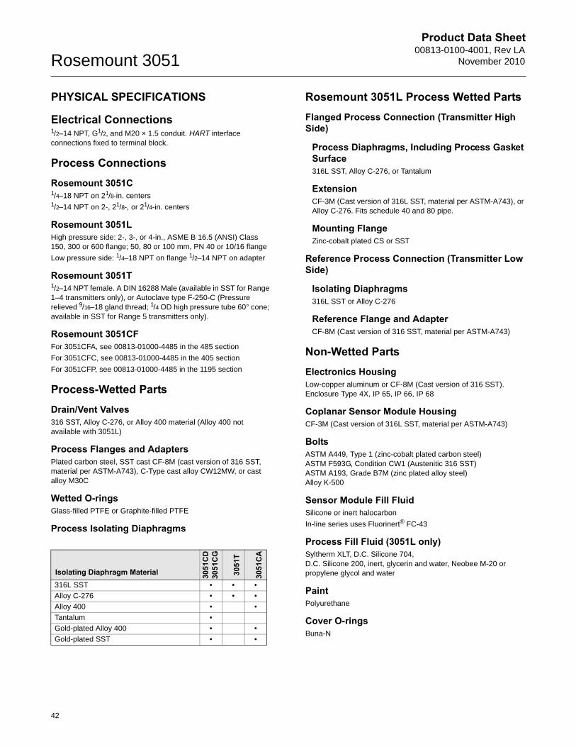
Product Data Sheet00813-0100-4001, Rev LA
November 2010Rosemount 3051
PHYSICAL SPECIFICATIONS
Electrical Connections1/2–14 NPT, G1/2, and M20 × 1.5 conduit. HART interface connections fixed to terminal block.
Process ConnectionsRosemount 3051C1/4–18 NPT on 21/8-in. centers1/2–14 NPT on 2-, 21/8-, or 21/4-in. centers
Rosemount 3051LHigh pressure side: 2-, 3-, or 4-in., ASME B 16.5 (ANSI) Class 150, 300 or 600 flange; 50, 80 or 100 mm, PN 40 or 10/16 flange
Low pressure side: 1/4–18 NPT on flange 1/2–14 NPT on adapter
Rosemount 3051T1/2–14 NPT female. A DIN 16288 Male (available in SST for Range 1–4 transmitters only), or Autoclave type F-250-C (Pressure relieved 9/16–18 gland thread; 1/4 OD high pressure tube 60° cone; available in SST for Range 5 transmitters only).
Rosemount 3051CFFor 3051CFA, see 00813-01000-4485 in the 485 section
For 3051CFC, see 00813-01000-4485 in the 405 section
For 3051CFP, see 00813-01000-4485 in the 1195 section
Process-Wetted PartsDrain/Vent Valves316 SST, Alloy C-276, or Alloy 400 material (Alloy 400 not available with 3051L)
Process Flanges and AdaptersPlated carbon steel, SST cast CF-8M (cast version of 316 SST, material per ASTM-A743), C-Type cast alloy CW12MW, or cast alloy M30C
Wetted O-ringsGlass-filled PTFE or Graphite-filled PTFE
Process Isolating Diaphragms
Rosemount 3051L Process Wetted PartsFlanged Process Connection (Transmitter High Side)
Process Diaphragms, Including Process Gasket Surface316L SST, Alloy C-276, or Tantalum
ExtensionCF-3M (Cast version of 316L SST, material per ASTM-A743), or Alloy C-276. Fits schedule 40 and 80 pipe.
Mounting FlangeZinc-cobalt plated CS or SST
Reference Process Connection (Transmitter Low Side)
Isolating Diaphragms316L SST or Alloy C-276
Reference Flange and AdapterCF-8M (Cast version of 316 SST, material per ASTM-A743)
Non-Wetted PartsElectronics HousingLow-copper aluminum or CF-8M (Cast version of 316 SST). Enclosure Type 4X, IP 65, IP 66, IP 68
Coplanar Sensor Module HousingCF-3M (Cast version of 316L SST, material per ASTM-A743)
BoltsASTM A449, Type 1 (zinc-cobalt plated carbon steel)ASTM F593G, Condition CW1 (Austenitic 316 SST)ASTM A193, Grade B7M (zinc plated alloy steel)Alloy K-500
Sensor Module Fill FluidSilicone or inert halocarbon
In-line series uses Fluorinert® FC-43
Process Fill Fluid (3051L only)Syltherm XLT, D.C. Silicone 704, D.C. Silicone 200, inert, glycerin and water, Neobee M-20 or propylene glycol and water
PaintPolyurethane
Cover O-ringsBuna-N
Isolating Diaphragm Material 3051
CD
3051
CG
3051
T
3051
CA
316L SST • • •
Alloy C-276 • • •
Alloy 400 • •
Tantalum •
Gold-plated Alloy 400 • •
Gold-plated SST • •
42
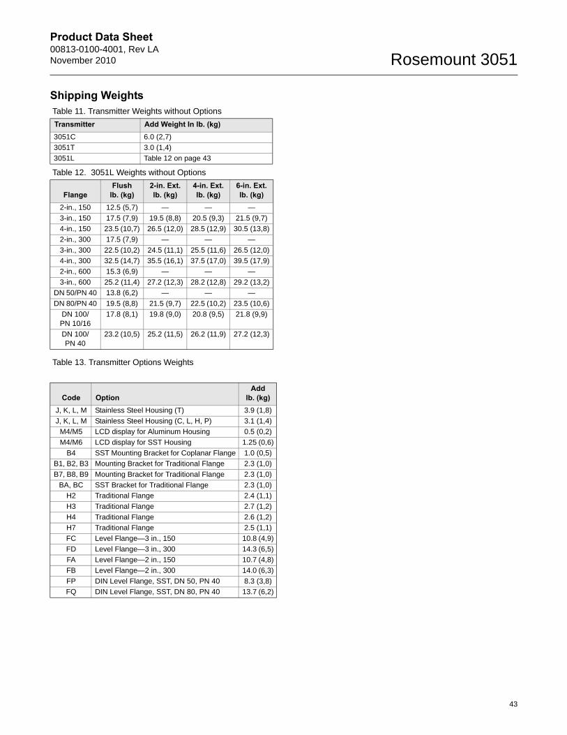
Product Data Sheet00813-0100-4001, Rev LANovember 2010 Rosemount 3051
Shipping Weights
Table 13. Transmitter Options Weights
Table 11. Transmitter Weights without Options
Transmitter Add Weight In lb. (kg)3051C 6.0 (2,7)
3051T 3.0 (1,4)
3051L Table 12 on page 43
Table 12. 3051L Weights without Options
FlangeFlush
lb. (kg)2-in. Ext.lb. (kg)
4-in. Ext.lb. (kg)
6-in. Ext.lb. (kg)
2-in., 150 12.5 (5,7) — — —
3-in., 150 17.5 (7,9) 19.5 (8,8) 20.5 (9,3) 21.5 (9,7)
4-in., 150 23.5 (10,7) 26.5 (12,0) 28.5 (12,9) 30.5 (13,8)
2-in., 300 17.5 (7,9) — — —
3-in., 300 22.5 (10,2) 24.5 (11,1) 25.5 (11,6) 26.5 (12,0)
4-in., 300 32.5 (14,7) 35.5 (16,1) 37.5 (17,0) 39.5 (17,9)
2-in., 600 15.3 (6,9) — — —
3-in., 600 25.2 (11,4) 27.2 (12,3) 28.2 (12,8) 29.2 (13,2)
DN 50/PN 40 13.8 (6,2) — — —
DN 80/PN 40 19.5 (8,8) 21.5 (9,7) 22.5 (10,2) 23.5 (10,6)
DN 100/PN 10/16
17.8 (8,1) 19.8 (9,0) 20.8 (9,5) 21.8 (9,9)
DN 100/PN 40
23.2 (10,5) 25.2 (11,5) 26.2 (11,9) 27.2 (12,3)
Code OptionAdd
lb. (kg)J, K, L, M Stainless Steel Housing (T) 3.9 (1,8)
J, K, L, M Stainless Steel Housing (C, L, H, P) 3.1 (1,4)
M4/M5 LCD display for Aluminum Housing 0.5 (0,2)
M4/M6 LCD display for SST Housing 1.25 (0,6)
B4 SST Mounting Bracket for Coplanar Flange 1.0 (0,5)
B1, B2, B3 Mounting Bracket for Traditional Flange 2.3 (1,0)
B7, B8, B9 Mounting Bracket for Traditional Flange 2.3 (1,0)
BA, BC SST Bracket for Traditional Flange 2.3 (1,0)
H2 Traditional Flange 2.4 (1,1)
H3 Traditional Flange 2.7 (1,2)
H4 Traditional Flange 2.6 (1,2)
H7 Traditional Flange 2.5 (1,1)
FC Level Flange—3 in., 150 10.8 (4,9)
FD Level Flange—3 in., 300 14.3 (6,5)
FA Level Flange—2 in., 150 10.7 (4,8)
FB Level Flange—2 in., 300 14.0 (6,3)
FP DIN Level Flange, SST, DN 50, PN 40 8.3 (3,8)
FQ DIN Level Flange, SST, DN 80, PN 40 13.7 (6,2)
43
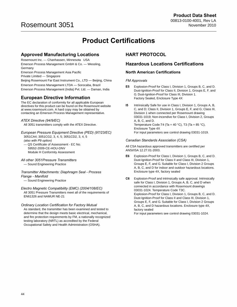
Product Data Sheet00813-0100-4001, Rev LA
November 2010Rosemount 3051
Product Certifications
Approved Manufacturing LocationsRosemount Inc. — Chanhassen, Minnesota USAEmerson Process Management GmbH & Co. — Wessling, GermanyEmerson Process Management Asia Pacific Private Limited — SingaporeBeijing Rosemount Far East Instrument Co., LTD — Beijing, China
Emerson Process Management LTDA — Sorocaba, BrazilEmerson Process Management (India) Pvt. Ltd. — Daman, India
European Directive InformationThe EC declaration of conformity for all applicable European directives for this product can be found on the Rosemount website at www.rosemount.com. A hard copy may be obtained by contacting an Emerson Process Management representative.
ATEX Directive (94/9/EC)All 3051 transmitters comply with the ATEX Directive.
European Pressure Equipment Directive (PED) (97/23/EC)3051CA4; 3051CG2, 3, 4, 5; 3051CD2, 3, 4, 5 (also with P9 option)— QS Certificate of Assessment - EC No.
59552-2009-CE-HOU-DNVModule H Conformity Assessment
All other 3051Pressure Transmitters— Sound Engineering Practice
Transmitter Attachments: Diaphragm Seal - Process Flange - Manifold
— Sound Engineering Practice
Electro Magnetic Compatibility (EMC) (2004/108/EC)All 3051 Pressure Transmitters meet all of the requirements of EN61326 and NAMUR NE-21
Ordinary Location Certification for Factory MutualAs standard, the transmitter has been examined and tested to determine that the design meets basic electrical, mechanical, and fire protection requirements by FM, a nationally recognized testing laboratory (NRTL) as accredited by the Federal Occupational Safety and Health Administration (OSHA).
HART PROTOCOL
Hazardous Locations CertificationsNorth American Certifications
FM Approvals
E5 Explosion-Proof for Class I, Division 1, Groups B, C, and D. Dust-Ignition-Proof for Class II, Division 1, Groups E, F, and G. Dust-Ignition-Proof for Class III, Division 1. Factory Sealed, Enclosure Type 4X
I5 Intrinsically Safe for use in Class I, Division 1, Groups A, B, C, and D; Class II, Division 1, Groups E, F, and G; Class III, Division 1 when connected per Rosemount drawing 03031-1019; Non-incendive for Class I, Division 2, Groups A, B, C, and D.Temperature Code:T4 (Ta = 40 °C), T3 (Ta = 85 °C), Enclosure Type 4XFor input parameters see control drawing 03031-1019.
Canadian Standards Association (CSA)
All CSA hazardous approved transmitters are certified per ANSI/ISA 12.27.01-2003.
E6 Explosion-Proof for Class I, Division 1, Groups B, C, and D. Dust-Ignition-Proof for Class II and Class III, Division 1, Groups E, F, and G. Suitable for Class I, Division 2 Groups A, B, C, and D for indoor and outdoor hazardous locations. Enclosure type 4X, factory sealed
C6 Explosion-Proof and intrinsically safe approval. Intrinsically safe for Class I, Division 1, Groups A, B, C, and D when connected in accordance with Rosemount drawings 03031-1024. Temperature Code T3C.Explosion-Proof for Class I, Division 1, Groups B, C, and D. Dust-Ignition-Proof for Class II and Class III, Division 1, Groups E, F, and G. Suitable for Class I, Division 2 Groups A, B, C, and D hazardous locations. Enclosure type 4X, factory sealedFor input parameters see control drawing 03031-1024.
44
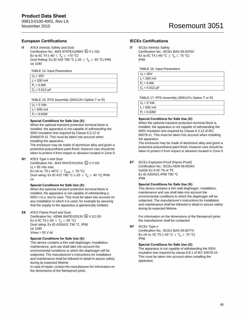
Product Data Sheet00813-0100-4001, Rev LANovember 2010 Rosemount 3051
European CertificationsI1 ATEX Intrinsic Safety and Dust
Certification No.: BAS 97ATEX1089X II 1 GD Ex ia IIC T4 (–60 Ta +70 °C)Dust Rating: Ex tD A20 T80 °C (–20 Ta 40 °C) IP66
1180
Special Conditions for Safe Use (X): When the optional transient protection terminal block is installed, the apparatus is not capable of withstanding the 500V insulation test required by Clause 6.3.12 of EN60079-11. This must be taken into account when installing the apparatus.The enclosure may be made of aluminium alloy and given a protective polyurethane paint finish; however care should be taken to protect it from impact or abrasion located in Zone 0.
N1 ATEX Type n and Dust Certification No.: BAS 00ATEX3105X II 3 GD Ui = 55 Vdc maxEx nA nL T5 (–40°C Tamb 70 °C)Dust rating: Ex tD A22 T80 °C (–20 Ta 40 °C) IP66
Special Conditions for Safe Use (X): When the optional transient protection terminal block is installed, the apparatus is not capable of withstanding a 500V r.m.s. test to case. This must be taken into account on any installation in which it is used, for example by assuring that the supply to the apparatus is galvanically isolated.
E8 ATEX Flame-Proof and Dust Certification No.: KEMA 00ATEX2013X II 1/2 GD Ex d IIC T6 (–50 Ta 65 °C)Dust rating: Ex tD A20/A21 T90 °C, IP66
1180Vmax = 55 V dc
Special Conditions for Safe Use (X): This device contains a thin wall diaphragm. Installation, maintenance, and use shall take into account the environmental conditions to which the diaphragm will be subjected. The manufacturer’s instructions for installation and maintenance shall be followed in detail to assure safety during its expected lifetime.In case of repair, contact the manufacturer for information on the dimensions of the flameproof joints.
IECEx CertificationsI7 IECEx Intrinsic Safety
Certification No.: IECEx BAS 09.0076XEx ia IIC T4 (–60 °C Ta 70 °C)IP66
Special Conditions for Safe Use (X): When the optional transient protection terminal block is installed, the apparatus is not capable of withstanding the 500V insulation test required by Clause 6.3.12 of IEC 60079-11. This must be taken into account when installing the apparatus.The enclosure may be made of aluminium alloy and given a protective polyurethane paint finish; however care should be taken to protect it from impact or abrasion located in Zone 0.
E7 IECEx Explosion-Proof (Flame-Proof) Certification No.: IECEx KEM 09.0034XGa/Gb Ex d IIC T6 or T5 Ex tD A20/A21 IP66 T90 °CIP66
Special Conditions for Safe Use (X): This device contains a thin wall diaphragm. Installation, maintenance and use shall take into account the environmental conditions to which the diaphragm will be subjected. The manufacturer's instructions for installation and maintenance shall be followed in detail to assure safety during its expected lifetime.
For information on the dimensions of the flameproof joints the manufacturer shall be contacted.
N7 IECEx Type n Certification No.: IECEx BAS 09.0077XEx nA nL IIC T5 (–40 °C Ta 70 °C)IP66
Special Conditions for Safe Use (X): The apparatus is not capable of withstanding the 500V insulation test required by clause 6.8.1 of IEC 60079-15. This must be taken into account when installing the apparatus.
TABLE 14. Input Parameters
Ui = 30V
Ii = 200 mA
Pi = 0.9W
Ci = 0.012 µF
TABLE 15. RTD Assembly (3051CFx Option T or R)
Ui = 5 Vdc
Ii = 500 mA
Pi = 0.63W
TABLE 16. Input Parameters
Ui = 30V
Ii = 200 mA
Pi = 0.9W
Ci = 0.012 µF
TABLE 17. RTD Assembly (3051CFx Option T or R)
Ui = 5 Vdc
Ii = 500 mA
Pi = 0.63W
45
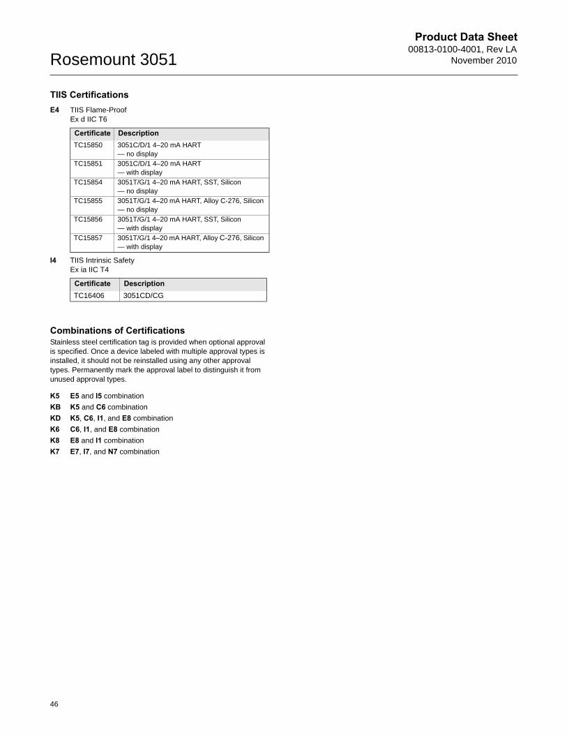
Product Data Sheet00813-0100-4001, Rev LA
November 2010Rosemount 3051
TIIS CertificationsE4 TIIS Flame-Proof
Ex d IIC T6
I4 TIIS Intrinsic SafetyEx ia IIC T4
Combinations of CertificationsStainless steel certification tag is provided when optional approval is specified. Once a device labeled with multiple approval types is installed, it should not be reinstalled using any other approval types. Permanently mark the approval label to distinguish it from unused approval types.
K5 E5 and I5 combination
KB K5 and C6 combination
KD K5, C6, I1, and E8 combination
K6 C6, I1, and E8 combination
K8 E8 and I1 combination
K7 E7, I7, and N7 combination
Certificate DescriptionTC15850 3051C/D/1 4–20 mA HART
— no display
TC15851 3051C/D/1 4–20 mA HART — with display
TC15854 3051T/G/1 4–20 mA HART, SST, Silicon — no display
TC15855 3051T/G/1 4–20 mA HART, Alloy C-276, Silicon — no display
TC15856 3051T/G/1 4–20 mA HART, SST, Silicon — with display
TC15857 3051T/G/1 4–20 mA HART, Alloy C-276, Silicon — with display
Certificate DescriptionTC16406 3051CD/CG
46
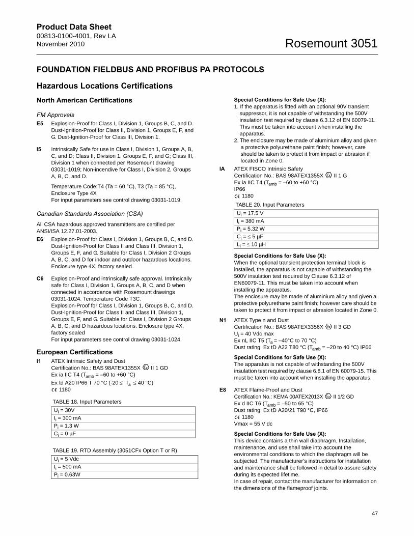
Product Data Sheet00813-0100-4001, Rev LANovember 2010 Rosemount 3051
FOUNDATION FIELDBUS AND PROFIBUS PA PROTOCOLS
Hazardous Locations CertificationsNorth American Certifications
FM ApprovalsE5 Explosion-Proof for Class I, Division 1, Groups B, C, and D.
Dust-Ignition-Proof for Class II, Division 1, Groups E, F, and G. Dust-Ignition-Proof for Class III, Division 1.
I5 Intrinsically Safe for use in Class I, Division 1, Groups A, B, C, and D; Class II, Division 1, Groups E, F, and G; Class III, Division 1 when connected per Rosemount drawing 03031-1019; Non-incendive for Class I, Division 2, Groups A, B, C, and D.
Temperature Code:T4 (Ta = 60 °C), T3 (Ta = 85 °C), Enclosure Type 4XFor input parameters see control drawing 03031-1019.
Canadian Standards Association (CSA)
All CSA hazardous approved transmitters are certified per ANSI/ISA 12.27.01-2003.
E6 Explosion-Proof for Class I, Division 1, Groups B, C, and D. Dust-Ignition-Proof for Class II and Class III, Division 1, Groups E, F, and G. Suitable for Class I, Division 2 Groups A, B, C, and D for indoor and outdoor hazardous locations. Enclosure type 4X, factory sealed
C6 Explosion-Proof and intrinsically safe approval. Intrinsically safe for Class I, Division 1, Groups A, B, C, and D when connected in accordance with Rosemount drawings 03031-1024. Temperature Code T3C.Explosion-Proof for Class I, Division 1, Groups B, C, and D. Dust-Ignition-Proof for Class II and Class III, Division 1, Groups E, F, and G. Suitable for Class I, Division 2 Groups A, B, C, and D hazardous locations. Enclosure type 4X, factory sealedFor input parameters see control drawing 03031-1024.
European CertificationsI1 ATEX Intrinsic Safety and Dust
Certification No.: BAS 98ATEX1355X II 1 GD Ex ia IIC T4 (Tamb = –60 to +60 °C)
Ex td A20 IP66 T 70 °C (-20 Ta 40 °C) 1180
Special Conditions for Safe Use (X): 1. If the apparatus is fitted with an optional 90V transient
suppressor, it is not capable of withstanding the 500V insulation test required by clause 6.3.12 of EN 60079-11. This must be taken into account when installing the apparatus.
2. The enclosure may be made of aluminium alloy and given a protective polyurethane paint finish; however, care should be taken to protect it from impact or abrasion if located in Zone 0.
IA ATEX FISCO Intrinsic Safety Certification No.: BAS 98ATEX1355X II 1 G Ex ia IIC T4 (Tamb = –60 to +60 °C)IP66
1180
Special Conditions for Safe Use (X): When the optional transient protection terminal block is installed, the apparatus is not capable of withstanding the 500V insulation test required by Clause 6.3.12 of EN60079-11. This must be taken into account when installing the apparatus.The enclosure may be made of aluminium alloy and given a protective polyurethane paint finish; however care should be taken to protect it from impact or abrasion located in Zone 0.
N1 ATEX Type n and Dust Certification No.: BAS 98ATEX3356X II 3 GD Ui = 40 Vdc maxEx nL IIC T5 (Ta = –40°C to 70 °C)Dust rating: Ex tD A22 T80 °C (Tamb = –20 to 40 °C) IP66
Special Conditions for Safe Use (X): The apparatus is not capable of withstanding the 500V insulation test required by clause 6.8.1 of EN 60079-15. This must be taken into account when installing the apparatus.
E8 ATEX Flame-Proof and Dust Certification No.: KEMA 00ATEX2013X II 1/2 GD Ex d IIC T6 (Tamb = –50 to 65 °C)Dust rating: Ex tD A20/21 T90 °C, IP66
1180Vmax = 55 V dc
Special Conditions for Safe Use (X): This device contains a thin wall diaphragm. Installation, maintenance, and use shall take into account the environmental conditions to which the diaphragm will be subjected. The manufacturer’s instructions for installation and maintenance shall be followed in detail to assure safety during its expected lifetime.In case of repair, contact the manufacturer for information on the dimensions of the flameproof joints.
TABLE 18. Input Parameters
Ui = 30V
Ii = 300 mA
Pi = 1.3 W
Ci = 0 µF
TABLE 19. RTD Assembly (3051CFx Option T or R)
Ui = 5 Vdc
Ii = 500 mA
Pi = 0.63W
TABLE 20. Input Parameters
Ui = 17.5 V
Ii = 380 mA
Pi = 5.32 W
Ci = 5 µF
Li = 10 µH
47
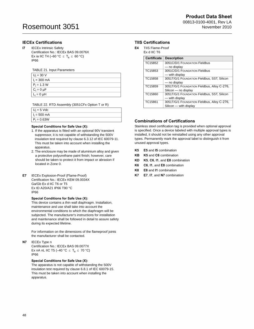
Product Data Sheet00813-0100-4001, Rev LA
November 2010Rosemount 3051
IECEx CertificationsI7 IECEx Intrinsic Safety
Certification No.: IECEx BAS 09.0076XEx ia IIC T4 (–60 °C Ta 60 °C)IP66
Special Conditions for Safe Use (X): 1. If the apparatus is fitted with an optional 90V transient
suppressor, it is not capable of withstanding the 500V insulation test required by clause 6.3.12 of IEC 60079-11. This must be taken into account when installing the apparatus.
2. The enclosure may be made of aluminium alloy and given a protective polyurethane paint finish; however, care should be taken to protect it from impact or abrasion if located in Zone 0.
E7 IECEx Explosion-Proof (Flame-Proof) Certification No.: IECEx KEM 09.0034XGa/Gb Ex d IIC T6 or T5 Ex tD A20/A21 IP66 T90 °CIP66
Special Conditions for Safe Use (X): This device contains a thin wall diaphragm. Installation, maintenance and use shall take into account the environmental conditions to which the diaphragm will be subjected. The manufacturer's instructions for installation and maintenance shall be followed in detail to assure safety during its expected lifetime.
For information on the dimensions of the flameproof joints the manufacturer shall be contacted.
N7 IECEx Type n Certification No.: IECEx BAS 09.0077XEx nA nL IIC T5 (–40 °C Ta 70 °C)IP66
Special Conditions for Safe Use (X): The apparatus is not capable of withstanding the 500V insulation test required by clause 6.8.1 of IEC 60079-15. This must be taken into account when installing the apparatus.
TIIS CertificationsE4 TIIS Flame-Proof
Ex d IIC T6
Combinations of CertificationsStainless steel certification tag is provided when optional approval is specified. Once a device labeled with multiple approval types is installed, it should not be reinstalled using any other approval types. Permanently mark the approval label to distinguish it from unused approval types.
K5 E5 and I5 combination
KB K5 and C6 combination
KD K5, C6, I1, and E8 combination
K6 C6, I1, and E8 combination
K8 E8 and I1 combination
K7 E7, I7, and N7 combination
TABLE 21. Input Parameters
Ui = 30 V
Ii = 300 mA
Pi = 1.3 W
Ci = 0 µF
Li = 0 µH
TABLE 22. RTD Assembly (3051CFx Option T or R)
Ui = 5 Vdc
Ii = 500 mA
Pi = 0.63W
Certificate DescriptionTC15852 3051C/D/1 FOUNDATION Fieldbus
— no displayTC15853 3051C/D/1 FOUNDATION Fieldbus
— with displayTC15858 3051T/G/1 FOUNDATION Fieldbus, SST, Silicon
— no displayTC15859 3051T/G/1 FOUNDATION Fieldbus, Alloy C-276,
Silicon — no displayTC15860 3051T/G/1 FOUNDATION Fieldbus, SST, Silicon
— with displayTC15861 3051T/G/1 FOUNDATION Fieldbus, Alloy C-276,
Silicon — with display
48
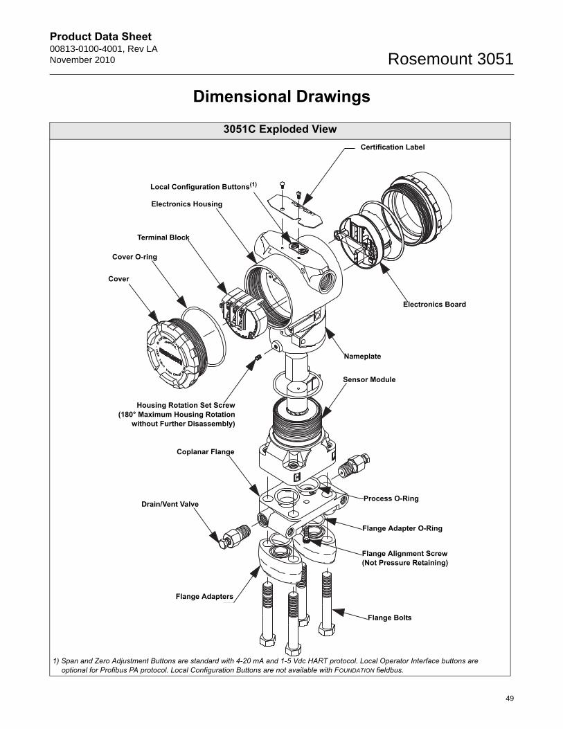
Product Data Sheet00813-0100-4001, Rev LANovember 2010 Rosemount 3051
Dimensional Drawings
3051C Exploded ViewCertification Label
Local Configuration Buttons(1)
Electronics Housing
Terminal Block
Cover O-ring
Cover
Electronics Board
Nameplate
Sensor Module
Housing Rotation Set Screw(180° Maximum Housing Rotation
without Further Disassembly)
Flange Alignment Screw (Not Pressure Retaining)
Flange Bolts
Flange Adapters
Drain/Vent Valve
Coplanar Flange
Flange Adapter O-Ring
Process O-Ring
1) Span and Zero Adjustment Buttons are standard with 4-20 mA and 1-5 Vdc HART protocol. Local Operator Interface buttons are optional for Profibus PA protocol. Local Configuration Buttons are not available with FOUNDATION fieldbus.
49
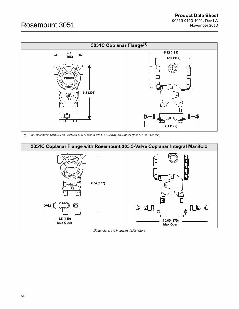
Product Data Sheet00813-0100-4001, Rev LA
November 2010Rosemount 3051
3051C Coplanar Flange(1)
(1) For FOUNDATION fieldbus and Profibus PA transmitters with LCD Display, housing length is 5.78 in. (147 mm).
8.2 (209)
4.1 (105)
6.4 (163)
4.45 (113)5.32 (135)
3051C Coplanar Flange with Rosemount 305 3-Valve Coplanar Integral Manifold
Dimensions are in inches (millimeters)
7.54 (192)
5.5 (140)Max Open 10.60 (270)
Max Open
50
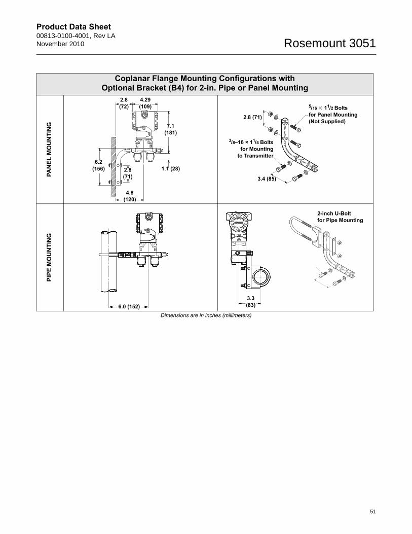
Product Data Sheet00813-0100-4001, Rev LANovember 2010 Rosemount 3051
Coplanar Flange Mounting Configurations with Optional Bracket (B4) for 2-in. Pipe or Panel Mounting
PAN
EL M
OU
NTI
NG
PIPE
MO
UN
TIN
G
Dimensions are in inches (millimeters)
4.29(109)
2.8(72)
7.1 (181)
2.8(71)
6.2(156)
4.8(120)
1.1 (28)
5/16 � 11/2 Bolts for Panel Mounting(Not Supplied)
3/8–16 × 11/4 Boltsfor Mounting
to Transmitter
2.8 (71)
3.4 (85)
6.0 (152)3.3(83)
2-inch U-Boltfor Pipe Mounting
51
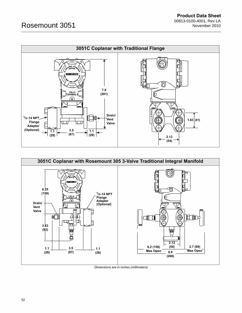
Product Data Sheet00813-0100-4001, Rev LA
November 2010Rosemount 3051
3051C Coplanar with Traditional Flange
1.1(28)
3.5 (87)
1.1 (28)
Drain/Vent Valve
1/2–14 NPTFlange
Adapter(Optional)
7.9 (201)
1.63 (41)
2.13 (54)
3051C Coplanar with Rosemount 305 3-Valve Traditional Integral Manifold
Dimensions are in inches (millimeters)
1.1(28)
3.5 (87)
1.1 (28)
Drain/Vent Valve
1/2–14 NPT Flange Adapter (Optional)
6.25 (159)
3.63 (92)
8.9 (266)
6.2 (158) Max Open
2.7 (69) Max Open
2.13 (54)
52
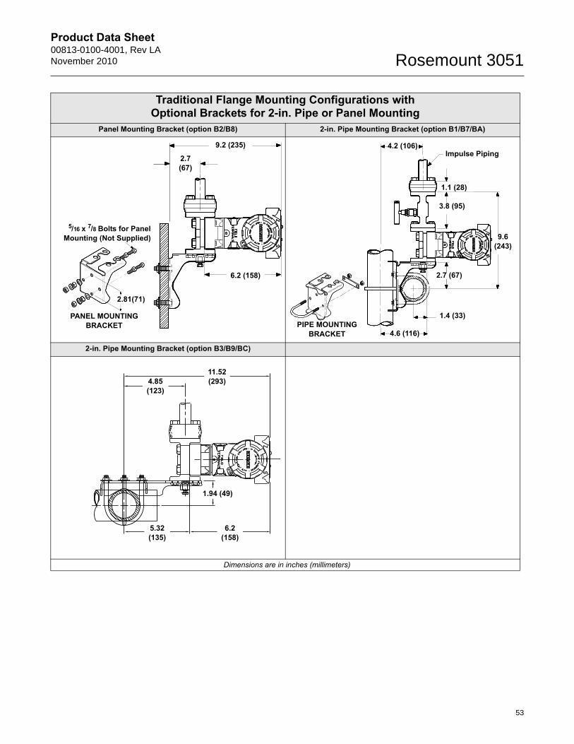
Product Data Sheet00813-0100-4001, Rev LANovember 2010 Rosemount 3051
Traditional Flange Mounting Configurations with Optional Brackets for 2-in. Pipe or Panel Mounting
Panel Mounting Bracket (option B2/B8) 2-in. Pipe Mounting Bracket (option B1/B7/BA)
2-in. Pipe Mounting Bracket (option B3/B9/BC)
Dimensions are in inches (millimeters)
9.2 (235)
2.7 (67)
6.2 (158)
PANEL MOUNTING BRACKET
2.81(71)
5/16 x 7/8 Bolts for PanelMounting (Not Supplied)
1.1 (28)
1.4 (33)
4.6 (116)
9.6 (243)
Impulse Piping
3.8 (95)
2.7 (67)
4.2 (106)
PIPE MOUNTING BRACKET
11.52 (293)4.85
(123)
6.2 (158)
5.32 (135)
1.94 (49)
53
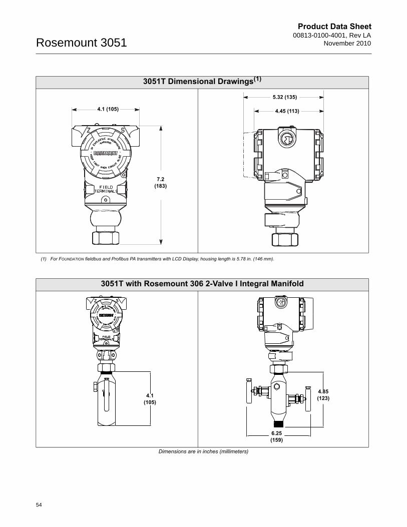
Product Data Sheet00813-0100-4001, Rev LA
November 2010Rosemount 3051
3051T Dimensional Drawings(1)
(1) For FOUNDATION fieldbus and Profibus PA transmitters with LCD Display, housing length is 5.78 in. (146 mm).
7.2(183)
4.1 (105)
5.32 (135)
4.45 (113)
3051T with Rosemount 306 2-Valve I Integral Manifold
Dimensions are in inches (millimeters)
4.1 (105)
4.85 (123)
6.25 (159)
54
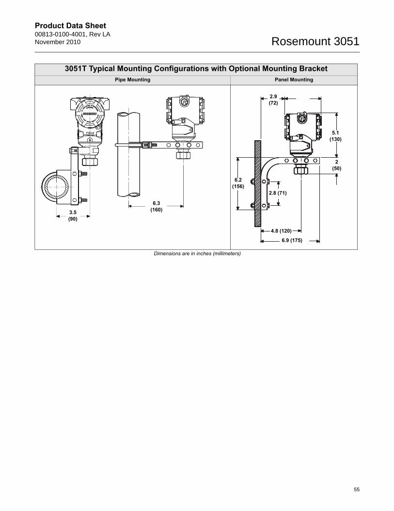
Product Data Sheet00813-0100-4001, Rev LANovember 2010 Rosemount 3051
3051T Typical Mounting Configurations with Optional Mounting BracketPipe Mounting Panel Mounting
Dimensions are in inches (millimeters)
3.5 (90)
6.3(160)
2(50)
6.2(156)
2.9(72)
2.8 (71)
4.8 (120)
6.9 (175)
5.1(130)
55
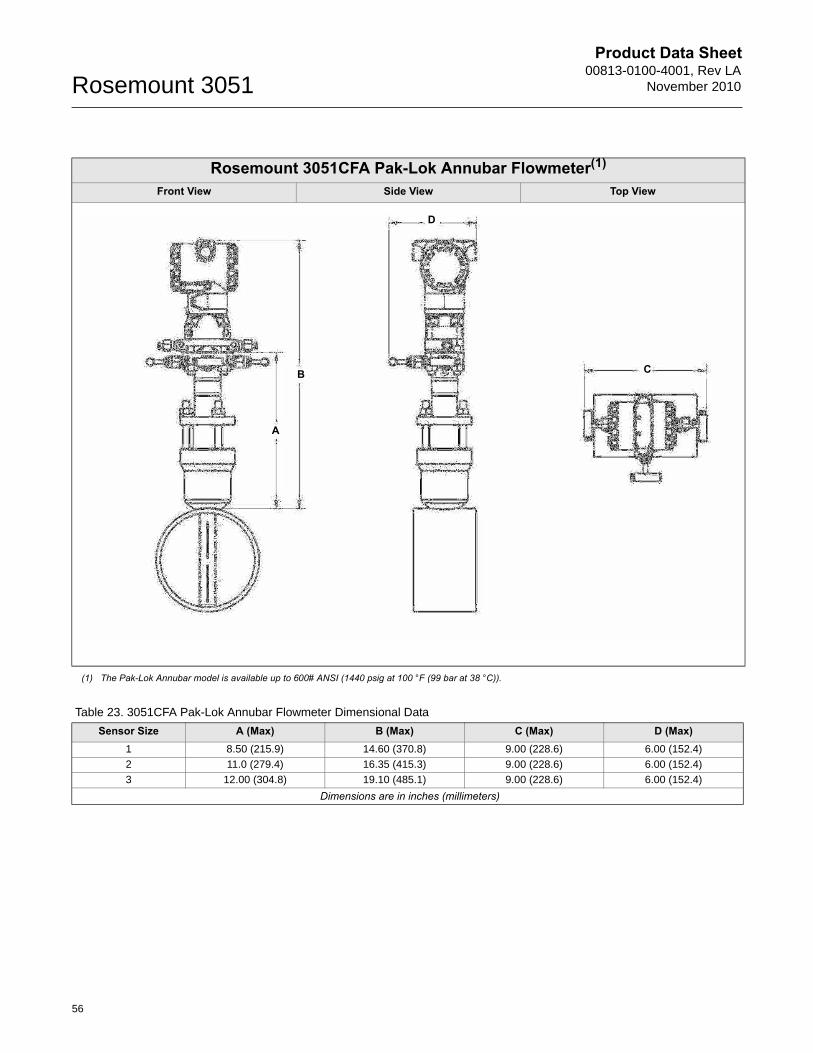
Product Data Sheet00813-0100-4001, Rev LA
November 2010Rosemount 3051
Rosemount 3051CFA Pak-Lok Annubar Flowmeter(1)
Front View Side View Top View
(1) The Pak-Lok Annubar model is available up to 600# ANSI (1440 psig at 100 °F (99 bar at 38 °C)).
B
A
D
C
Table 23. 3051CFA Pak-Lok Annubar Flowmeter Dimensional Data
Sensor Size A (Max) B (Max) C (Max) D (Max)1 8.50 (215.9) 14.60 (370.8) 9.00 (228.6) 6.00 (152.4)
2 11.0 (279.4) 16.35 (415.3) 9.00 (228.6) 6.00 (152.4)
3 12.00 (304.8) 19.10 (485.1) 9.00 (228.6) 6.00 (152.4)
Dimensions are in inches (millimeters)
56
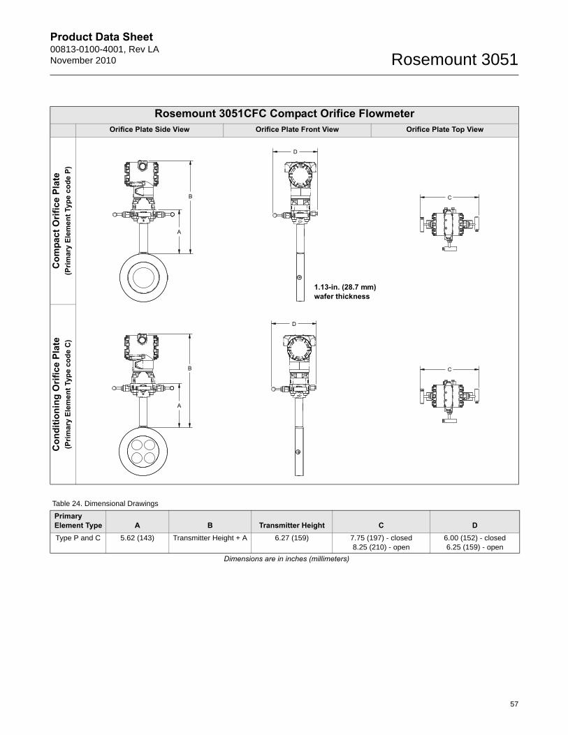
Product Data Sheet00813-0100-4001, Rev LANovember 2010 Rosemount 3051
Rosemount 3051CFC Compact Orifice Flowmeter Orifice Plate Side View Orifice Plate Front View Orifice Plate Top View
Com
pact
Orif
ice
Plat
e (P
rimar
y El
emen
t Typ
e co
de P
)C
ondi
tioni
ng O
rific
e Pl
ate
(Prim
ary
Elem
ent T
ype
code
C)
1.13-in. (28.7 mm) wafer thickness
Table 24. Dimensional Drawings
Primary Element Type A B Transmitter Height C DType P and C 5.62 (143) Transmitter Height + A 6.27 (159) 7.75 (197) - closed
8.25 (210) - open6.00 (152) - closed6.25 (159) - open
Dimensions are in inches (millimeters)
57
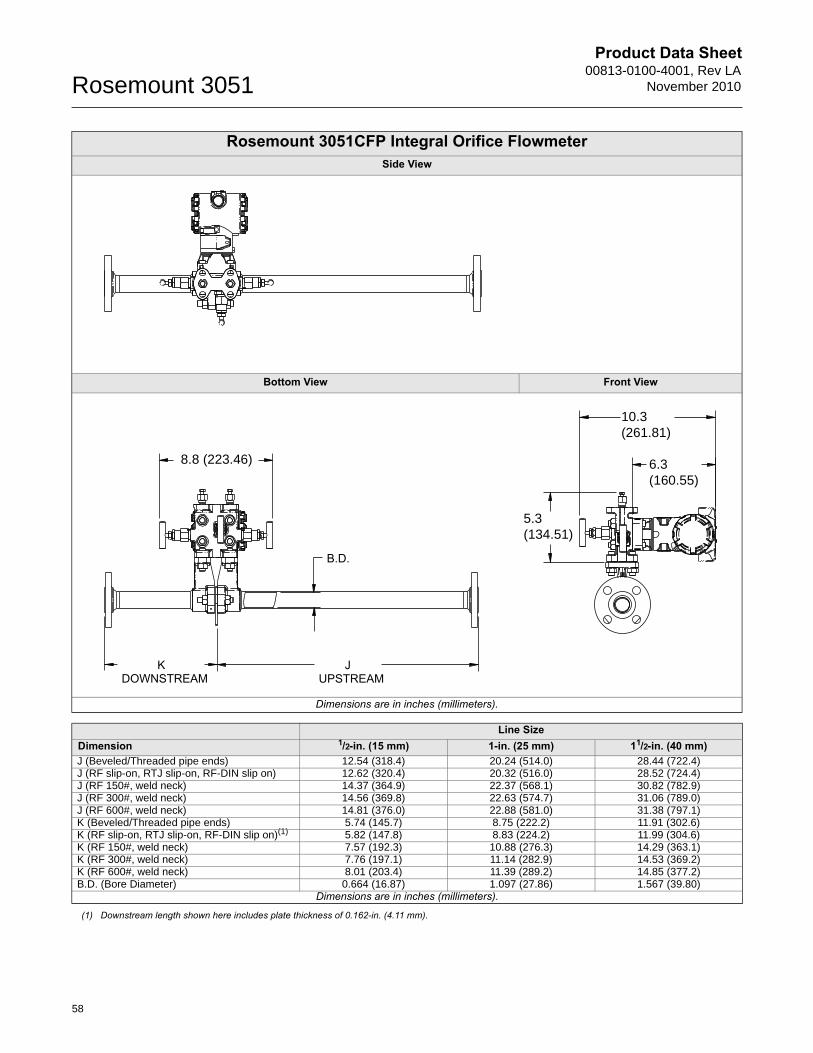
Product Data Sheet00813-0100-4001, Rev LA
November 2010Rosemount 3051
58
Rosemount 3051CFP Integral Orifice Flowmeter Side View
Bottom View Front View
Dimensions are in inches (millimeters).
Line SizeDimension 1/2-in. (15 mm) 1-in. (25 mm) 11/2-in. (40 mm)J (Beveled/Threaded pipe ends) 12.54 (318.4) 20.24 (514.0) 28.44 (722.4)J (RF slip-on, RTJ slip-on, RF-DIN slip on) 12.62 (320.4) 20.32 (516.0) 28.52 (724.4)J (RF 150#, weld neck) 14.37 (364.9) 22.37 (568.1) 30.82 (782.9)J (RF 300#, weld neck) 14.56 (369.8) 22.63 (574.7) 31.06 (789.0)J (RF 600#, weld neck) 14.81 (376.0) 22.88 (581.0) 31.38 (797.1)K (Beveled/Threaded pipe ends) 5.74 (145.7) 8.75 (222.2) 11.91 (302.6)K (RF slip-on, RTJ slip-on, RF-DIN slip on)(1) 5.82 (147.8) 8.83 (224.2) 11.99 (304.6)K (RF 150#, weld neck) 7.57 (192.3) 10.88 (276.3) 14.29 (363.1)K (RF 300#, weld neck) 7.76 (197.1) 11.14 (282.9) 14.53 (369.2)K (RF 600#, weld neck) 8.01 (203.4) 11.39 (289.2) 14.85 (377.2)B.D. (Bore Diameter) 0.664 (16.87) 1.097 (27.86) 1.567 (39.80)
Dimensions are in inches (millimeters).
(1) Downstream length shown here includes plate thickness of 0.162-in. (4.11 mm).
8.8 (223.46)
10.3(261.81)
6.3(160.55)
5.3(134.51)
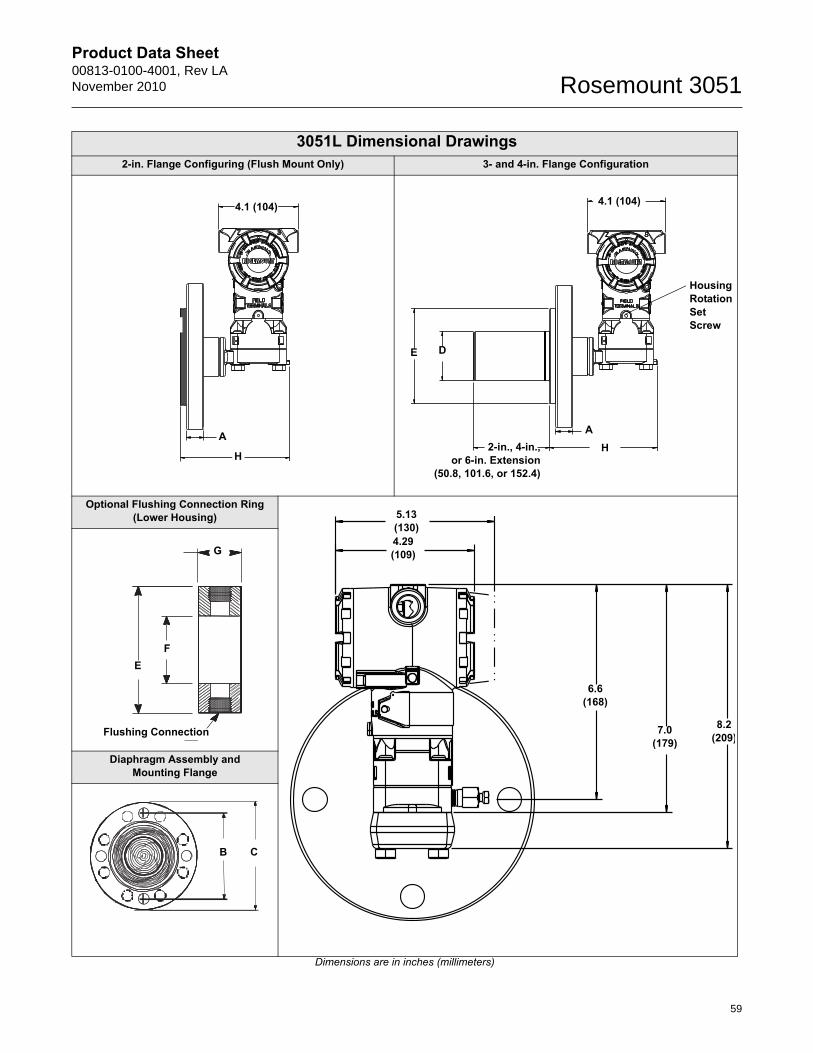
Product Data Sheet00813-0100-4001, Rev LANovember 2010 Rosemount 3051
59
3051L Dimensional Drawings2-in. Flange Configuring (Flush Mount Only) 3- and 4-in. Flange Configuration
Optional Flushing Connection Ring (Lower Housing)
Diaphragm Assembly and Mounting Flange
Dimensions are in inches (millimeters)
A
4.1 (104)
H
A
Housing Rotation SetScrew
2-in., 4-in.,or 6-in. Extension
(50.8, 101.6, or 152.4)
E
4.1 (104)
D
H
5.13 (130)
6.6(168)
8.2(209)
4.29(109)
7.0(179)
Flushing Connection
EF
G
CB
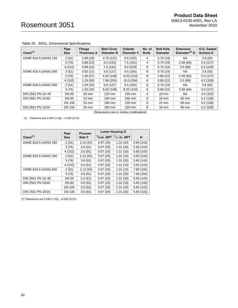
Product Data Sheet00813-0100-4001, Rev LA
November 2010Rosemount 3051
(1) Tolerances are 0.040 (1.02), –0.020 (0.51).
Table 25. 3051L Dimensional Specifications
Class(1)Pipe Size
Flange Thickness A
Bolt Circle Diameter B
Outside Diameter C
No. of Bolts
Bolt Hole Diameter
Extension Diameter(1) D
O.D. Gasket Surface E
ASME B16.5 (ANSI) 150 2 (51) 0.69 (18) 4.75 (121) 6.0 (152) 4 0.75 (19) NA 3.6 (92)
3 (76) 0.88 (22) 6.0 (152) 7.5 (191) 4 0.75 (19) 2.58 (66) 5.0 (127)
4 (102) 0.88 (22) 7.5 (191) 9.0 (229) 8 0.75 (19) 3.5 (89) 6.2 (158)
ASME B16.5 (ANSI) 300 2 (51) 0.82 (21) 5.0 (127) 6.5 (165) 8 0.75 (19) NA 3.6 (92)
3 (76) 1.06 (27) 6.62 (168) 8.25 (210) 8 0.88 (22) 2.58 (66) 5.0 (127)
4 (102) 1.19 (30) 7.88 (200) 10.0 (254) 8 0.88 (22) 3.5 (89) 6.2 (158)
ASME B16.5 (ANSI) 600 2 (51) 1.00 (25) 5.0 (127) 6.5 (165) 8 0.75 (19) NA 3.6 (92)
3 (76) 1.25 (32) 6.62 (168) 8.25 (210) 8 0.88 (22) 2.58 (66) 5.0 (127)
DIN 2501 PN 10–40 DN 50 20 mm 125 mm 165 mm 4 18 mm NA 4.0 (102)
DIN 2501 PN 25/40 DN 80 24 mm 160 mm 200 mm 8 18 mm 66 mm 5.4 (138)
DN 100 24 mm 190 mm 235 mm 8 22 mm 89 mm 6.2 (158)
DIN 2501 PN 10/16 DN 100 20 mm 180 mm 220 mm 8 18 mm 89 mm 6.2 (158)
Dimensions are in inches (millimeters)
(1) Tolerance are 0.040 (1.02), - 0.020 (0.51)
Class(1)Pipe Size
Process Side F
Lower Housing G
H1/4-in. NPT 1/2 -in. NPTASME B16.5 (ANSI) 150 2 (51) 2.12 (54) 0.97 (25) 1.31 (33) 5.65 (143)
3 (76) 3.6 (91) 0.97 (25) 1.31 (33) 5.65 (143)
4 (102) 3.6 (91) 0.97 (25) 1.31 (33) 5.65 (143)
ASME B16.5 (ANSI) 300 2 (51) 2.12 (54) 0.97 (25) 1.31 (33) 5.65 (143)
3 (76) 3.6 (91) 0.97 (25) 1.31 (33) 5.65 (143)
4 (102) 3.6 (91) 0.97 (25) 1.31 (33) 5.65 (143)
ASME B16.5 (ANSI) 600 2 (51) 2.12 (54) 0.97 (25) 1.31 (33) 7.65 (194)
3 (76) 3.6 (91) 0.97 (25) 1.31 (33) 7.65 (194)
DIN 2501 PN 10–40 DN 50 2.4 (61) 0.97 (25) 1.31 (33) 5.65 (143)
DIN 2501 PN 25/40 DN 80 3.6 (91) 0.97 (25) 1.31 (33) 5.65 (143)
DN 100 3.6 (91) 0.97 (25) 1.31 (33) 5.65 (143)
DIN 2501 PN 10/16 DN 100 3.6 (91) 0.97 (25) 1.31 (33) 5.65 (143)
60
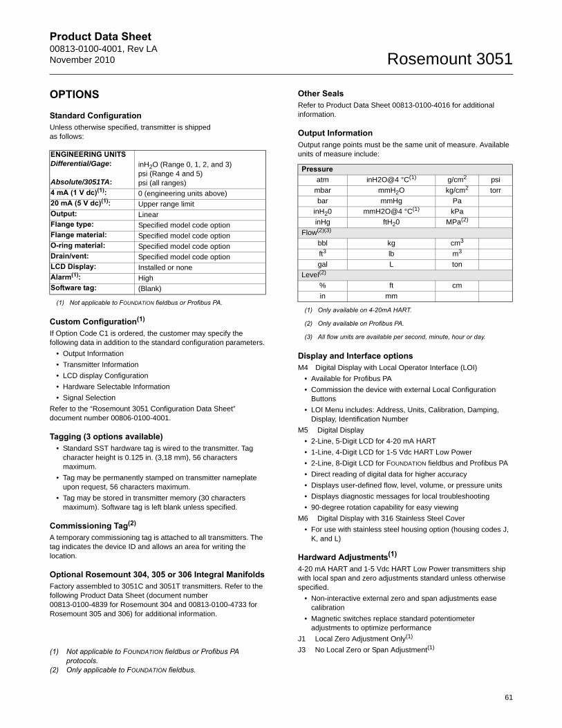
Product Data Sheet00813-0100-4001, Rev LANovember 2010 Rosemount 3051
OPTIONS
Standard ConfigurationUnless otherwise specified, transmitter is shippedas follows:
Custom Configuration(1)
If Option Code C1 is ordered, the customer may specify the following data in addition to the standard configuration parameters.
• Output Information
• Transmitter Information
• LCD display Configuration
• Hardware Selectable Information
• Signal Selection
Refer to the “Rosemount 3051 Configuration Data Sheet” document number 00806-0100-4001.
Tagging (3 options available)• Standard SST hardware tag is wired to the transmitter. Tag
character height is 0.125 in. (3,18 mm), 56 characters maximum.
• Tag may be permanently stamped on transmitter nameplate upon request, 56 characters maximum.
• Tag may be stored in transmitter memory (30 characters maximum). Software tag is left blank unless specified.
Commissioning Tag(2)
A temporary commissioning tag is attached to all transmitters. The tag indicates the device ID and allows an area for writing the location.
Optional Rosemount 304, 305 or 306 Integral ManifoldsFactory assembled to 3051C and 3051T transmitters. Refer to the following Product Data Sheet (document number 00813-0100-4839 for Rosemount 304 and 00813-0100-4733 for Rosemount 305 and 306) for additional information.
Other SealsRefer to Product Data Sheet 00813-0100-4016 for additional information.
Output InformationOutput range points must be the same unit of measure. Available units of measure include:
Display and Interface optionsM4 Digital Display with Local Operator Interface (LOI)
• Available for Profibus PA
• Commission the device with external Local Configuration Buttons
• LOI Menu includes: Address, Units, Calibration, Damping, Display, Identification Number
M5 Digital Display
• 2-Line, 5-Digit LCD for 4-20 mA HART
• 1-Line, 4-Digit LCD for 1-5 Vdc HART Low Power
• 2-Line, 8-Digit LCD for FOUNDATION fieldbus and Profibus PA
• Direct reading of digital data for higher accuracy
• Displays user-defined flow, level, volume, or pressure units
• Displays diagnostic messages for local troubleshooting
• 90-degree rotation capability for easy viewing
M6 Digital Display with 316 Stainless Steel Cover
• For use with stainless steel housing option (housing codes J, K, and L)
Hardward Adjustments(1)
4-20 mA HART and 1-5 Vdc HART Low Power transmitters ship with local span and zero adjustments standard unless otherwise specified.
• Non-interactive external zero and span adjustments ease calibration
• Magnetic switches replace standard potentiometer adjustments to optimize performance
J1 Local Zero Adjustment Only(1)
J3 No Local Zero or Span Adjustment(1)
ENGINEERING UNITSDifferential/Gage:
Absolute/3051TA:
inH2O (Range 0, 1, 2, and 3)psi (Range 4 and 5)psi (all ranges)
4 mA (1 V dc)(1):
(1) Not applicable to FOUNDATION fieldbus or Profibus PA.
0 (engineering units above)20 mA (5 V dc)(1): Upper range limitOutput: LinearFlange type: Specified model code optionFlange material: Specified model code optionO-ring material: Specified model code optionDrain/vent: Specified model code optionLCD Display: Installed or noneAlarm(1): HighSoftware tag: (Blank)
(1) Not applicable to FOUNDATION fieldbus or Profibus PA protocols.
(2) Only applicable to FOUNDATION fieldbus.
Pressureatm inH2O@4 °C(1)
(1) Only available on 4-20mA HART.
g/cm2 psi
mbar mmH2O kg/cm2 torr
bar mmHg Pa
inH20 mmH2O@4 °C(1) kPa
inHg ftH20 MPa(2)
(2) Only available on Profibus PA.
Flow(2)(3)
(3) All flow units are available per second, minute, hour or day.
bbl kg cm3
ft3 lb m3
gal L ton
Level(2)
% ft cm
in mm
61
Product Data Sheet00813-0100-4001, Rev LA
November 2010Rosemount 3051
Standard Terms and Conditions of Sale can be found at www.rosemount.com\terms_of_saleThe Emerson logo is a trade mark and service mark of Emerson Electric Co. Rosemount, Annubar, ProPlate, and the Rosemount logotype are registered trademarks of Rosemount Inc.
Transient ProtectionT1 Integral Transient Protection Terminal BlockMeets IEEE C62.41, Category Location B
6 kV crest (0.5 s - 100 kHz)
3 kV crest (8 × 20 microseconds)
6 kV crest (1.2 × 50 microseconds)
Bolts for Flanges and Adapters• Options permit bolts for flanges and adapters to be obtained in
various materials
• Standard material is plated carbon steel per ASTM A449, Type 1
L4 Austenitic 316 Stainless Steel Bolts
L5 ASTM A 193, Grade B7M Bolts
L6 Alloy K-500 Bolts
Conduit PlugDO 316 SST Conduit Plug
Single 316 SST conduit plug replaces carbon steel plug
Rosemount 3051C Coplanar Flange and 3051T Bracket OptionB4 Bracket for 2-in. Pipe or Panel Mounting
• For use with the standard Coplanarflange configuration
• Bracket for mounting of transmitter on 2-in. pipe or panel
• Stainless steel construction with stainless steel bolts
Rosemount 3051C Traditional Flange Bracket OptionsB1 Bracket for 2-in. Pipe Mounting
• For use with the traditional flange option
• Bracket for mounting on 2-in. pipe
• Carbon steel construction with carbonsteel bolts
• Coated with polyurethane paint
B2 Bracket for Panel Mounting
• For use with the traditional flange option
• Bracket for mounting transmitter on wallor panel
• Carbon steel construction with carbonsteel bolts
• Coated with polyurethane paint
B3 Flat Bracket for 2-in. Pipe Mounting
• For use with the traditional flange option
• Bracket for vertical mounting of transmitter on 2-in. pipe
• Carbon steel construction with carbonsteel bolts
• Coated with polyurethane paint
B7 B1 Bracket with SST Bolts
• Same bracket as the B1 option with Series 300 stainless steel bolts
B8 B2 Bracket with SST Bolts
• Same bracket as the B2 option with Series 300 stainless steel bolts
B9 B3 Bracket with SST Bolts
• Same bracket as the B3 option with Series 300 stainless steel bolts
BA Stainless Steel B1 Bracket with SST Bolts
• B1 bracket in stainless steel with Series 300 stainless steel bolts
BC Stainless Steel B3 Bracket with SST Bolts
• B3 bracket in stainless steel with Series 300 stainless steel bolts
Emerson Process Management
00813-0100-4001 Rev LA, 11/10
PlantWeb is a registered trademark of one of the Emerson Process Management group of companies.Instrument Toolkit is a registered trademark of Emerson Process Management.Complete Point Solutions, Coplanar and Multivariable are trademarks of Rosemount Inc.HART is a registered trademark of the HART Communications Foundation.Syltherm 800, Dow Corning, and D.C. are registered trademarks of Dow Corning Co.Neobee M-20 is a registered trademark of Stephan Chemical Co.The 3-A symbol is a registered trademark of the 3-A Sanitary Standards Symbol Council.FOUNDATION fieldbus is a registered trademark of the Fieldbus Foundation.Fluorinert is a registered trademark of 3M Company.© 2010 Rosemount, Inc. All rights reserved.
All other marks are the property of their respective owners.
Rosemount Inc.8200 Market BoulevardChanhassen, MN 55317 USAT (U.S.) 1 800 999 9307T (International) (952) 906 8888F (952) 949 7001
www.rosemount.com
Emerson Process Management Heath PlaceBognor RegisWest Sussex PO22 9SHEnglandT 44 (0) 1243 863121F 44 (0) 1243 867554
Emerson Process Management Asia Pacific Private Limited1 Pandan CrescentSingapore 128461T (65) 6777 8211F (65) 6777 [email protected]