Embed Size (px)
DESCRIPTION
• Coplanar ™ platform enables integrated pressure, flow, and level solutions HART Protocol C1 Option Configuration Data Sheet . . . . . . . . . . . . . . . . . . . . . . . page 39 Product Offering. . . . . . . . . . . . . . . . . . . . . . . . . . . . . . . . . . . . . . . . . . . . . . . . . . . . . page 3
Citation preview
Product Data Sheet00813-0100-4001, Rev GA
Catalog 2006 - 2007 Rosemount 3051
Rosemount 3051 Pressure Transmitter
HART®
AND FOUNDATION™
FIELDBUS
PROTOCOLS
• Best-in-Class performance, 0.04% High
Accuracy option
• Industry first five-year stability under actual
process conditions
• Unmatched Dynamic Performance
• Coplanar™ platform enables integrated
pressure, flow, and level solutions
• Advanced PlantWeb® Functionality
www.rosemount.com
Contents
Product Offering. . . . . . . . . . . . . . . . . . . . . . . . . . . . . . . . . . . . . . . . . . . . . . . . . . . . .page 3
Specifications. . . . . . . . . . . . . . . . . . . . . . . . . . . . . . . . . . . . . . . . . . . . . . . . . . . . . . .page 4
Product Certifications. . . . . . . . . . . . . . . . . . . . . . . . . . . . . . . . . . . . . . . . . . . . . . . .page 12
HART Protocol . . . . . . . . . . . . . . . . . . . . . . . . . . . . . . . . . . . . . . . . . . . . . . . . . . .page 12
Fieldbus Protocol . . . . . . . . . . . . . . . . . . . . . . . . . . . . . . . . . . . . . . . . . . . . . . . . .page 15
Dimensional Drawings. . . . . . . . . . . . . . . . . . . . . . . . . . . . . . . . . . . . . . . . . . . . . . .page 17
Ordering Information . . . . . . . . . . . . . . . . . . . . . . . . . . . . . . . . . . . . . . . . . . . . . . . .page 25
HART Protocol C1 Option Configuration Data Sheet . . . . . . . . . . . . . . . . . . . . . . .page 39
Product Data Sheet00813-0100-4001, Rev GA
Catalog 2006 - 2007Rosemount 3051
Setting the Standard for Pressure Measurement
Industry’s best total performance, a flexible Coplanar platform, and guaranteed 5- year stability, has made the
Rosemount 3051 the standard in pressure measurement.
Industry’s best total performance of ±0.15%
Total performance is the true measure of “real-world”
transmitter performance. Using superior sensor
technology and engineered for optimal performance,
the 3051 delivers unprecedented ±0.04% reference
accuracy, resulting in total operating performance of
±0.15%. Superior total performance equates to
reduced variability and improved plant safety.
Five year installed stability of ±0.125%
Transmitter stability is a critical measure of
transmitter performance over time. Through
aggressive simulation testing beyond standard IEC
770 testing, the 3051 has proven its ability to
maintain performance over a five year period under
the most demanding process conditions. Superior
transmitter stability reduces calibration frequency to
save operation and maintenance costs.
Unmatched dynamic performance
In dynamic applications, speed of measurement is as
important as repeatability. The 3051 responds up to
eight times faster than the typical pressure
transmitter to detect and control variations quickly
and efficiently. Superior dynamic response yields
more accurate measurements to reduce variability
and increase profitability.
Coplanar platform enables complete point
solutions
The versatile Coplanar platform design enables the
best process connection for pressure, flow and level
applications. Right out of the box, the solution arrives
factory calibrated, pressure-tested, and ready to
install. Only the 3051 has a flexible design to reduce
engineering and inventory costs.
Advanced PlantWeb Functionality
The 3051 powers the PlantWeb
architecture by delivering the best
sensor and transmitter, best installation
practices, and best in class field
intelligence. One component is the
enhanced diagnostic capabilities in
FOUNDATION fieldbus that provide an increase in
process visibility, enabling proactive maintenance
and improving process availability.
Rosemount Pressure Solutions
Rosemount 3051S Series of InstrumentationScalable pressure, flow and level measurement solutions improve
installation and maintenance practices.
Rosemount 3095MV Mass Flow TransmitterAccurately measures differential pressure, static pressure and
process temperature to dynamically calculate fully compensated
mass flow.
Rosemount 305 and 306 Integral ManifoldsFactory-assembled, calibrated and seal-tested manifolds reduce
on-site installation costs.
Rosemount 1199 Diaphragm SealsProvides reliable, remote measurements of process pressure and
protects the transmitter from hot, corrosive, or viscous fluids.
Orifice Plate Primary Element Systems: Rosemount
1495 and 1595 Orifice Plates, 1496 Flange Unions and
1497 Meter SectionsA comprehensive offering of orifice plates, flange unions and
meter sections that is easy to specify and order. The 1595
Conditioning Orifice provides superior performance in tight fit
applications.
Annubar® Flowmeter Series: Rosemount 3051SFA,
3095MFA, and 485
The state-of-the-art, fifth generation Rosemount 485 Annubar
combined with the 3051S or 3095MV MultiVariable transmitter
creates an accurate, repeatable and dependable insertion-type
flowmeter.
Compact Orifice Flowmeter Series: Rosemount
3051SFC, 3095MFC, and 405
Compact Orifice Flowmeters can be installed between existing
flanges, up to a Class 600 (PN100) rating. In tight fit applications,
a conditioning orifice plate version is available, requiring only two
diameters of straight run upstream.
ProPlate® Flowmeter Series: Rosemount ProPlate,
Mass ProPlate, and 1195
These integral orifice flowmeters eliminate the inaccuracies that
become more pronounced in small orifice line installations. The
completely assembled, ready to install flowmeters reduce cost and
simplify installation.
2
Product Data Sheet00813-0100-4001, Rev GA
Catalog 2006 - 2007 Rosemount 3051
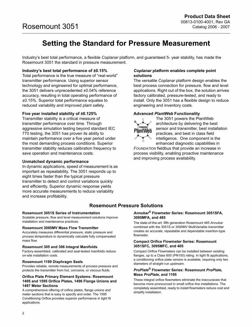
Product OfferingRosemount 3051C Differential, Gage, and Absolute
See ordering information on page 25.
• Performance up to 0.04% accuracy
• Five year installed stability of 0.125%
• Coplanar platform enables integrated manifold, primary element and diaphragm seal solutions
• Calibrated spans/ranges from 0.1 inH2O to 4000 psi (0,25 mbar to 276 bar)
• 316L SST, Hastelloy® C276, Monel®, Tantalum, Gold-plated Monel, or Gold-plated 316L SST process isolators
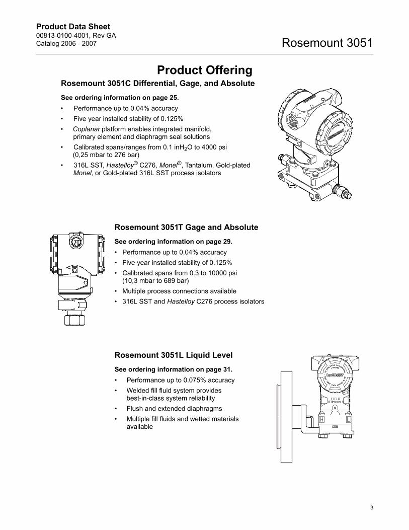
Rosemount 3051T Gage and Absolute
See ordering information on page 29.
• Performance up to 0.04% accuracy
• Five year installed stability of 0.125%
• Calibrated spans from 0.3 to 10000 psi(10,3 mbar to 689 bar)
• Multiple process connections available
• 316L SST and Hastelloy C276 process isolators
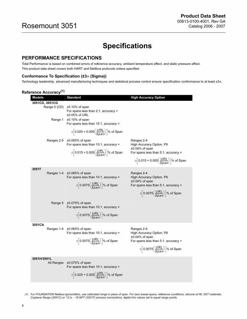
Rosemount 3051L Liquid Level
See ordering information on page 31.
• Performance up to 0.075% accuracy
• Welded fill fluid system provides best-in-class system reliability
• Flush and extended diaphragms
• Multiple fill fluids and wetted materials available
3
Product Data Sheet00813-0100-4001, Rev GA
Catalog 2006 - 2007Rosemount 3051
4
Specifications
Reference Accuracy(1)
Models Standard High Accuracy Option
3051CD, 3051CG
Range 0 (CD) ±0.10% of span
For spans less than 2:1, accuracy =
±0.05% of URL
Range 1 ±0.10% of span
For spans less than 15:1, accuracy =
Ranges 2-5 ±0.065% of span
For spans less than 10:1, accuracy =
Ranges 2-4
High Accuracy Option, P8
±0.04% of span
For spans less than 5:1, accuracy =
3051T
Ranges 1-4 ±0.065% of span
For spans less than 10:1, accuracy =
Ranges 2-4
High Accuracy Option, P8
±0.04% of span
For spans less than 5:1, accuracy =
Range 5 ±0.075% of span
For spans less than 10:1, accuracy =
3051CA
Ranges 1-4 ±0.065% of span
For spans less than 10:1, accuracy =
Ranges 2-4
High Accuracy Option, P8
±0.04% of span
For spans less than 5:1, accuracy =
3051H/3051L
All Ranges ±0.075% of span
For spans less than 10:1, accuracy =
(1) For FOUNDATION fieldbus transmitters, use calibrated range in place of span. For zero based spans, reference conditions, silicone oil fill, SST materials, Coplanar flange (3051C) or 1/2 in. - 18 NPT (3051T) process connections, digital trim values set to equal range points.
0.025 0.005+URL
Span---------------⎝ ⎠
⎛ ⎞ % of Span±
0.015 0.005+URL
Span---------------⎝ ⎠
⎛ ⎞ % of Span±
0.015 0.005+URL
Span---------------⎝ ⎠
⎛ ⎞ % of Span±
0.0075URL
Span---------------⎝ ⎠
⎛ ⎞ % of Span±
0.0075URL
Span---------------⎝ ⎠
⎛ ⎞ % of Span±
0.0075URL
Span---------------⎝ ⎠
⎛ ⎞ % of Span±
0.0075URL
Span---------------⎝ ⎠
⎛ ⎞ % of Span±
0.0075URL
Span---------------⎝ ⎠
⎛ ⎞ % of Span±
0.025 0.005+URL
Span---------------⎝ ⎠
⎛ ⎞ % of Span±
PERFORMANCE SPECIFICATIONSTotal Performance is based on combined errors of reference accuracy, ambient temperature effect, and static pressure effect.
This product data sheet covers both HART and fieldbus protocols unless specified.
Conformance To Specification (±3σ (Sigma))
Technology leadership, advanced manufacturing techniques and statistical process control ensure specification conformance to at least ±3σ.
Product Data Sheet00813-0100-4001, Rev GA
Catalog 2006 - 2007 Rosemount 3051
5
Total Performance
Long Term Stability
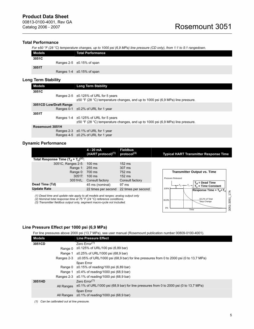
Dynamic Performance
Line Pressure Effect per 1000 psi (6,9 MPa)
For ±50 °F (28 °C) temperature changes, up to 1000 psi (6,9 MPa) line pressure (CD only), from 1:1 to 5:1 rangedown.
Models Total Performance
3051C
Ranges 2-5 ±0.15% of span
3051T
Ranges 1-4 ±0.15% of span
Models Long Term Stability
3051C
Ranges 2-5 ±0.125% of URL for 5 years
±50 °F (28 °C) temperature changes, and up to 1000 psi (6,9 MPa) line pressure.
3051CD Low/Draft Range
Ranges 0-1 ±0.2% of URL for 1 year
3051T
Ranges 1-4 ±0.125% of URL for 5 years
±50 °F (28 °C) temperature changes, and up to 1000 psi (6,9 MPa) line pressure.
Rosemount 3051H
Ranges 2-3
Ranges 4-5
±0.1% of URL for 1 year
±0.2% of URL for 1 year
4 - 20 mA
(HART protocol)(1)Fieldbus
protocol(3) Typical HART Transmitter Response Time
Total Response Time (Td + Tc)(2):
3051C, Ranges 2-5:
Range 1:
Range 0:
3051T:
3051H/L:
100 ms
255 ms
700 ms
100 ms
Consult factory
152 ms
307 ms
752 ms
152 ms
Consult factory
Dead Time (Td) 45 ms (nominal) 97 ms
Update Rate 22 times per second 22 times per second
(1) Dead time and update rate apply to all models and ranges; analog output only(2) Nominal total response time at 75 °F (24 °C) reference conditions. (3) Transmitter fieldbus output only, segment macro-cycle not included.
TcTd
Td = Dead TimeTc = Time Constant
Pressure Released
Response Time = Td+Tc
63.2% of TotalStep Change
Time0%
100%
36.8%
Transmitter Output vs. Time
3051
-305
1_17
A
For line pressures above 2000 psi (13,7 MPa), see user manual (Rosemount publication number 00809-0100-4001).
Models Line Pressure Effect
3051CD Zero Error(1)
±0.125% of URL/100 psi (6,89 bar)Range 0
Range 1 ±0.25% of URL/1000 psi (68,9 bar)
Ranges 2-3 ±0.05% of URL/1000 psi (68,9 bar) for line pressures from 0 to 2000 psi (0 to 13,7 MPa)
Range 0
Span Error
±0.15% of reading/100 psi (6,89 bar)
Range 1 ±0.4% of reading/1000 psi (68,9 bar)
Ranges 2-3 ±0.1% of reading/1000 psi (68,9 bar)
3051HD Zero Error(1)
±0.1% of URL/1000 psi (68,9 bar) for line pressures from 0 to 2000 psi (0 to 13,7 MPa)All Ranges
All Ranges
Span Error
±0.1% of reading/1000 psi (68,9 bar)
(1) Can be calibrated out at line pressure.
Product Data Sheet00813-0100-4001, Rev GA
Catalog 2006 - 2007Rosemount 3051
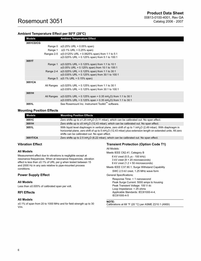
Ambient Temperature Effect per 50°F (28°C)
Mounting Position Effects
Vibration Effect
All Models
Measurement effect due to vibrations is negligible except at
resonance frequencies. When at resonance frequencies, vibration
effect is less than ±0.1% of URL per g when tested between 15
and 2000 Hz in any axis relative to pipe-mounted process
conditions.
Power Supply Effect
All Models
Less than ±0.005% of calibrated span per volt.
RFI Effects
All Models
±0.1% of span from 20 to 1000 MHz and for field strength up to 30
V/m.
Transient Protection (Option Code T1)
All Models:
Meets IEEE C62.41, Category B
6 kV crest (0.5 μs - 100 kHz)
3 kV crest (8 × 20 microseconds)
6 kV crest (1.2 × 50 microseconds)
Meets IEEE C37.90.1, Surge Withstand Capability
SWC 2.5 kV crest, 1.25 MHz wave form
General Specifications:
Response Time: < 1 nanosecond
Peak Surge Current: 5000 amps to housing
Peak Transient Voltage: 100 V dc
Loop Impedance: < 25 ohms
Applicable Standards: IEC61000-4-4,
IEC61000-4-5
NOTE:Calibrations at 68 °F (20 °C) per ASME Z210.1 (ANSI)
Models Ambient Temperature Effect
3051CD/CG
Range 0 ±(0.25% URL + 0.05% span)
Range 1 ±(0.1% URL + 0.25% span)
Ranges 2-5 ±(0.0125% URL + 0.0625% span) from 1:1 to 5:1
±(0.025% URL + 0.125% span) from 5:1 to 100:1
3051T
Range 1 ±(0.025% URL + 0.125% span) from 1:1 to 10:1
±(0.05% URL + 0.125% span) from 10:1 to 100:1
Range 2-4 ±(0.025% URL + 0.125% span) from 1:1 to 30:1
±(0.035% URL + 0.125% span) from 30:1 to 100:1
Range 5 ±(0.1% URL + 0.15% span)
3051CA
All Ranges ±(0.025% URL + 0.125% span) from 1:1 to 30:1
±(0.035% URL + 0.125% span) from 30:1 to 100:1
3051H
All Ranges ±(0.025% URL + 0.125% span + 0.35 inH2O) from 1:1 to 30:1
±(0.035% URL + 0.125% span + 0.35 inH2O) from 1:1 to 30:1
3051L See Rosemount Inc. Instrument Toolkit™ software.
Models Mounting Position Effects
3051C Zero shifts up to ±1.25 inH2O (3,11 mbar), which can be calibrated out. No span effect.
3051H Zero shifts up to ±5 inH2O (12,43 mbar), which can be calibrated out. No span effect.
3051L With liquid level diaphragm in vertical plane, zero shift of up to 1 inH2O (2,49 mbar). With diaphragm in
horizontal plane, zero shift of up to 5 inH2O (12,43 mbar) plus extension length on extended units. All zero
shifts can be calibrated out. No span effect.
3051T/CA Zero shifts up to 2.5 inH2O (6,22 mbar), which can be calibrated out. No span effect.
6
Product Data Sheet00813-0100-4001, Rev GA
Catalog 2006 - 2007 Rosemount 3051
FUNCTIONAL SPECIFICATIONS
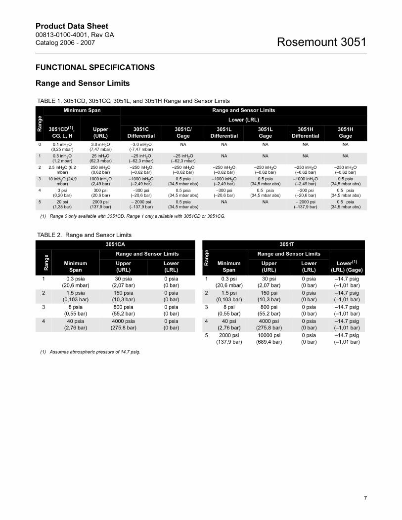
Range and Sensor Limits
TABLE 1. 3051CD, 3051CG, 3051L, and 3051H Range and Sensor Limits
Ra
ng
e
Minimum Span Range and Sensor Limits
3051CD(1),
CG, L, H
Upper
(URL)
Lower (LRL)
3051C
Differential
3051C/
Gage
3051L
Differential
3051L
Gage
3051H
Differential
3051H
Gage
0 0.1 inH2O(0,25 mbar)
3.0 inH2O(7,47 mbar)
–3.0 inH2O(-7,47 mbar)
NA NA NA NA NA
1 0.5 inH2O(1,2 mbar)
25 inH2O(62,3 mbar)
–25 inH2O(–62,3 mbar)
–25 inH2O(–62,3 mbar)
NA NA NA NA
2 2.5 inH2O (6,2 mbar)
250 inH2O(0,62 bar)
–250 inH2O(–0,62 bar)
–250 inH2O(–0,62 bar)
–250 inH2O(–0,62 bar)
–250 inH2O(–0,62 bar)
–250 inH2O(–0,62 bar)
–250 inH2O (–0,62 bar)
3 10 inH2O (24,9 mbar)
1000 inH2O (2,49 bar)
–1000 inH2O (–2,49 bar)
0.5 psia
(34,5 mbar abs)–1000 inH2O (–2,49 bar)
0.5 psia(34,5 mbar abs)
–1000 inH2O (–2,49 bar)
0.5 psia(34,5 mbar abs)
4 3 psi (0,20 bar)
300 psi (20,6 bar)
–300 psi(–20,6 bar)
0.5 psia
(34,5 mbar abs)–300 psi
(–20,6 bar)0.5 psia
(34,5 mbar abs)–300 psi
(–20,6 bar)0.5 psia
(34,5 mbar abs)
5 20 psi (1,38 bar)
2000 psi (137,9 bar)
– 2000 psi(–137,9 bar)
0.5 psia(34,5 mbar abs)
NA NA – 2000 psi (–137,9 bar)
0.5 psia(34,5 mbar abs)
(1) Range 0 only available with 3051CD. Range 1 only available with 3051CD or 3051CG.
TABLE 2. Range and Sensor Limits
3051CA
Ra
ng
e
3051T
Ra
ng
e
Minimum
Span
Range and Sensor Limits
Minimum
Span
Range and Sensor Limits
Lower(1)
(LRL) (Gage)
Upper
(URL)
Lower
(LRL)
Upper
(URL)
Lower
(LRL)
1 0.3 psia
(20,6 mbar)
30 psia
(2,07 bar)
0 psia
(0 bar)
1 0.3 psi
(20,6 mbar)
30 psi
(2,07 bar)
0 psia
(0 bar)
–14.7 psig
(–1,01 bar)
2 1.5 psia
(0,103 bar)
150 psia
(10,3 bar)
0 psia
(0 bar)
2 1.5 psi
(0,103 bar)
150 psi
(10,3 bar)
0 psia
(0 bar)
–14.7 psig
(–1,01 bar)
3 8 psia
(0,55 bar)
800 psia
(55,2 bar)
0 psia
(0 bar)
3 8 psi
(0,55 bar)
800 psi
(55,2 bar)
0 psia
(0 bar)
–14.7 psig
(–1,01 bar)
4 40 psia
(2,76 bar)
4000 psia
(275,8 bar)
0 psia
(0 bar)
4 40 psi
(2,76 bar)
4000 psi
(275,8 bar)
0 psia
(0 bar)
–14.7 psig
(–1,01 bar)
5 2000 psi
(137,9 bar)
10000 psi
(689,4 bar)
0 psia
(0 bar)
–14.7 psig
(–1,01 bar)
(1) Assumes atmospheric pressure of 14.7 psig.
7
Product Data Sheet00813-0100-4001, Rev GA
Catalog 2006 - 2007Rosemount 3051
Zero and Span Adjustment Requirements
(HART and Low Power)
Zero and span values can be set anywhere within the range limits
stated in Table 1 and Table 2.
Span must be greater than or equal to the minimum span stated in
Table 1 and Table 2.
Service
Liquid, gas, and vapor applications
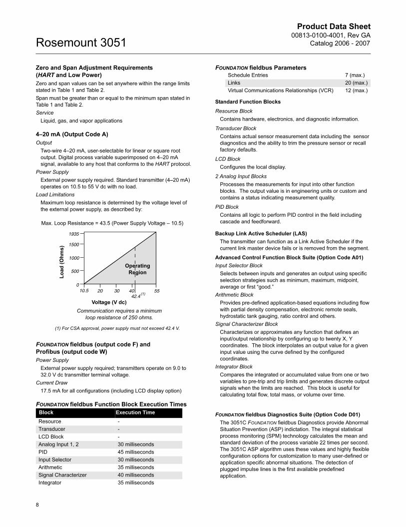
4–20 mA (Output Code A)
Output
Two-wire 4–20 mA, user-selectable for linear or square root
output. Digital process variable superimposed on 4–20 mA
signal, available to any host that conforms to the HART protocol.
Power Supply
External power supply required. Standard transmitter (4–20 mA)
operates on 10.5 to 55 V dc with no load.
Load Limitations
Maximum loop resistance is determined by the voltage level of
the external power supply, as described by:
FOUNDATION fieldbus (output code F) and
Profibus (output code W)
Power Supply
External power supply required; transmitters operate on 9.0 to
32.0 V dc transmitter terminal voltage.
Current Draw
17.5 mA for all configurations (including LCD display option)
FOUNDATION fieldbus Function Block Execution Times
FOUNDATION fieldbus Parameters
Standard Function Blocks
Resource Block
Contains hardware, electronics, and diagnostic information.
Transducer Block
Contains actual sensor measurement data including the sensor
diagnostics and the ability to trim the pressure sensor or recall
factory defaults.
LCD Block
Configures the local display.
2 Analog Input Blocks
Processes the measurements for input into other function
blocks. The output value is in engineering units or custom and
contains a status indicating measurement quality.
PID Block
Contains all logic to perform PID control in the field including
cascade and feedforward.
Backup Link Active Scheduler (LAS)
The transmitter can function as a Link Active Scheduler if the
current link master device fails or is removed from the segment.
Advanced Control Function Block Suite (Option Code A01)
Input Selector Block
Selects between inputs and generates an output using specific
selection strategies such as minimum, maximum, midpoint,
average or first “good.”
Arithmetic Block
Provides pre-defined application-based equations including flow
with partial density compensation, electronic remote seals,
hydrostatic tank gauging, ratio control and others.
Signal Characterizer Block
Characterizes or approximates any function that defines an
input/output relationship by configuring up to twenty X, Y
coordinates. The block interpolates an output value for a given
input value using the curve defined by the configured
coordinates.
Integrator Block
Compares the integrated or accumulated value from one or two
variables to pre-trip and trip limits and generates discrete output
signals when the limits are reached. This block is useful for
calculating total flow, total mass, or volume over time.
FOUNDATION fieldbus Diagnostics Suite (Option Code D01)
The 3051C FOUNDATION fieldbus Diagnostics provide Abnormal
Situation Prevention (ASP) indictation. The integral statistical
process monitoring (SPM) technology calculates the mean and
standard deviation of the process variable 22 times per second.
The 3051C ASP algorithm uses these values and highly flexible
configuration options for customization to many user-defined or
application specific abnormal situations. The detection of
plugged impulse lines is the first available predefined
application.
Block Execution Time
Resource -
Transducer -
LCD Block -
Analog Input 1, 2 30 milliseconds
PID 45 milliseconds
Input Selector 30 milliseconds
Arithmetic 35 milliseconds
Signal Characterizer 40 milliseconds
Integrator 35 milliseconds
Voltage (V dc)
Lo
ad
(O
hm
s)
Communication requires a minimum
loop resistance of 250 ohms.
(1) For CSA approval, power supply must not exceed 42.4 V.
Max. Loop Resistance = 43.5 (Power Supply Voltage – 10.5)
Operating
Region
Schedule Entries 7 (max.)
Links 20 (max.)
Virtual Communications Relationships (VCR) 12 (max.)
8
Product Data Sheet00813-0100-4001, Rev GA
Catalog 2006 - 2007 Rosemount 3051
9
Low Power (Output Code M)
Output
Three wire 1–5 V dc or 0.8–3.2 V dc (Option Code C2)
user-selectable output. Also user selectable for linear or square
root output configuration. Digital process variable superimposed
on voltage signal, available to any host conforming to the HART
protocol. Low-power transmitter operates on 6–12 V dc with no
load.
Power Consumption
3.0 mA, 18–36 mW
Minimum Load Impedance
100 kΩ (Vout wiring)
Indication
Optional 5-digit LCD display
Overpressure Limits
Rosemount 3051CD/CG
• Range 0: 750 psi (51,7 bar)
• Range 1: 2000 psig (137,9 bar)
• Ranges 2–5: 3626 psig (250 bar)
4500 psig (310,3 bar) for option code P9
Rosemount 3051CA
• Range 1: 750 psia (51,7 bar)
• Range 2: 1500 psia (103,4 bar)
• Range 3: 1600 psia (110,3 bar)
• Range 4: 6000 psia (413,7 bar)
Rosemount 3051H
• All Ranges: 3626 psig (25 MPa)
Rosemount 3051TG/TA
• Range 1: 750 psi (51,7 bar)
• Range 2: 1500 psi (103,4 bar)
• Range 3: 1600 psi (110,3 bar)
• Range 4: 6000 psi (413,7 bar)
• Range 5: 15000 psi (1034,2 bar)
For 3051L or Level Flange Option Codes FA, FB, FC, FD, FP, and
FQ, limit is 0 psia to the flange rating or sensor rating, whichever is
lower.
Static Pressure Limit
Rosemount 3051CD Only
Operates within specifications between static line pressures of
0.5 psia and 3626 psig (4500 psig for Option Code P9).
Range 0: 0.5 psia and 750 psig
Range 1: 0.5 psia and 2000 psig
Burst Pressure Limits
Burst pressure on Coplanar, traditional, or 3051H process flange is
10000 psig (69 MPa).
Burst pressure for the 3051T is
Ranges 1–4: 11000 psi (75,8 MPa)
Range 5: 26000 psig (179 MPa)
Failure Mode Alarm
Output Code A
If self-diagnostics detect a gross transmitter failure, the analog
signal will be driven either below 3.75 mA or to 21.75 mA to alert
the user. NAMUR-compliant values are available, option code
C4. High or low alarm signal is user-selectable by internal
jumper.
Output Code M
If self-diagnostics detect a gross transmitter failure, the analog
signal will be driven either below 0.94 V or above 5.4 V to alert
the user (below 0.75 V or above 4.4 V for Option C2). High or
low alarm signal is user-selectable by internal jumper.
Output Code F and W
If self-diagnostics detect a gross transmitter failure, that
information gets passed as a status along with the process
variable.
Temperature Limits
Ambient
–40 to 185 °F (–40 to 85 °C)
With integral meter: –4 to 175 °F (–20 to 80 °C)
Storage
–50 to 230 °F (–46 to 110 °C)
With integral meter: –40 to 185 °F (–40 to 85 °C)
Process
At atmospheric pressures and above. See Table 4
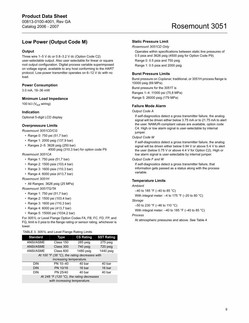
TABLE 3. 3051L and Level Flange Rating Limits
Standard Type CS Rating SST Rating
ANSI/ASME Class 150 285 psig 275 psig
ANSI/ASME Class 300 740 psig 720 psig
ANSI/ASME Class 600 1480 psig 1440 psig
At 100 °F (38 °C), the rating decreases with
increasing temperature.
DIN PN 10–40 40 bar 40 bar
DIN PN 10/16 16 bar 16 bar
DIN PN 25/40 40 bar 40 bar
At 248 °F (120 °C), the rating decreases
with increasing temperature.
Product Data Sheet00813-0100-4001, Rev GA
Catalog 2006 - 2007Rosemount 3051
Humidity Limits
0–100% relative humidity
Turn-On Time
Performance within specifications less than 2.0 seconds (10.0 s
for Profibus protocol) after power is applied to the transmitter
Volumetric Displacement
Less than 0.005 in3 (0,08 cm3)
Damping
Analog output response to a step input change is user-selectable
from 0 to 36 seconds for one time constant. This software damping
is in addition to sensor module response time.
PHYSICAL SPECIFICATIONS
Electrical Connections1/2–14 NPT, PG 13.5, G1/2, and M20 × 1.5 (CM20) conduit. HART
interface connections fixed to terminal block.
Process Connections
All Models except 3051L and 3051T1/4–18 NPT on 21/8-in. centers1/2–14 NPT on 2-, 21/8-, or 21/4-in. centers
Rosemount 3051L
High pressure side: 2-, 3-, or 4-in., ASME B 16.5 (ANSI) Class
150, 300 or 600 flange; 50, 80 or 100 mm, PN 40 or 10/16 flange
Low pressure side: 1/4–18 NPT on flange 1/2–14 NPT on adapter
Rosemount 3051T1/2–14 NPT female. A DIN 16288 Male (available in SST for
Range 1–4 transmitters only), or Autoclave type F-250-C
(Pressure relieved 9/16–18 gland thread; 1/4 OD high pressure
tube 60° cone; available in SST for Range 5 transmitters only).
Process-Wetted Parts
Drain/Vent Valves
316 SST, Hastelloy C276, or Monel material (Monel not
available with 3051L or 3051H)
Process Flanges and Adapters
Plated carbon steel, SST cast CF-8M (cast version of 316 SST,
material per ASTM-A743), C-Type cast alloy CW12MW, or
Monel cast alloy M30C
Wetted O-rings
Glass-filled PTFE or Graphite-filled PTFE
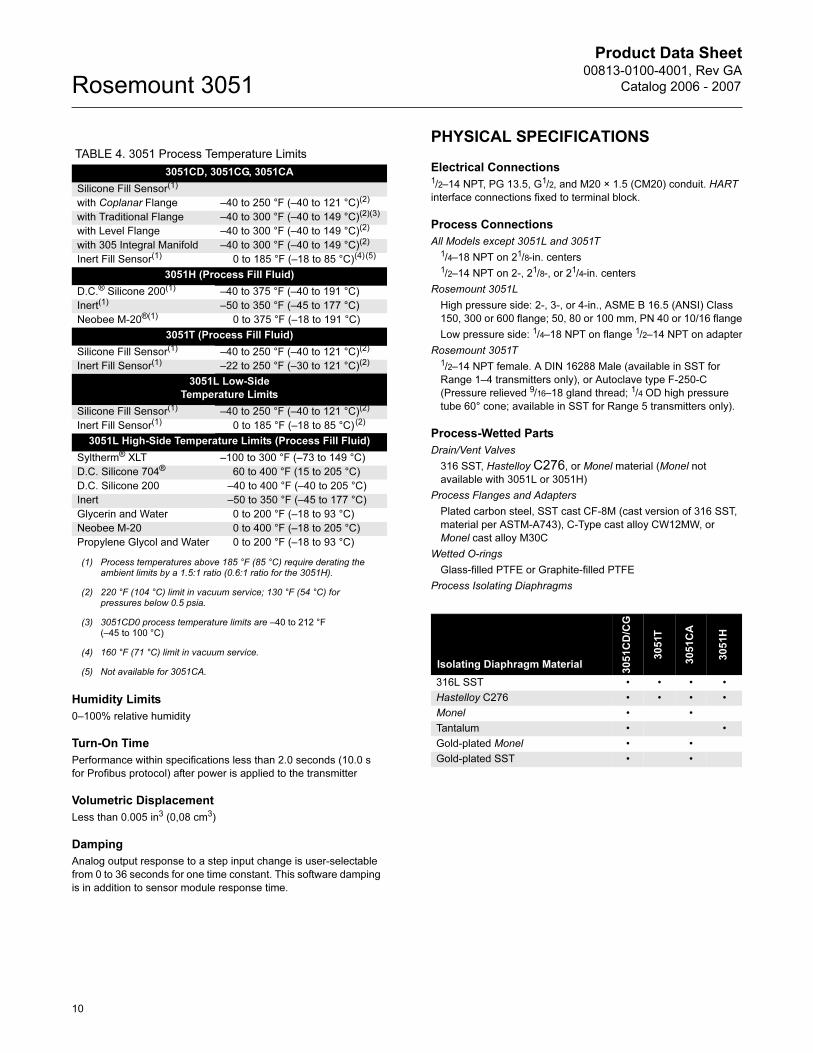
Process Isolating Diaphragms
TABLE 4. 3051 Process Temperature Limits
3051CD, 3051CG, 3051CA
Silicone Fill Sensor(1)
(1) Process temperatures above 185 °F (85 °C) require derating the ambient limits by a 1.5:1 ratio (0.6:1 ratio for the 3051H).
with Coplanar Flange –40 to 250 °F (–40 to 121 °C)(2)
(2) 220 °F (104 °C) limit in vacuum service; 130 °F (54 °C) for pressures below 0.5 psia.
with Traditional Flange –40 to 300 °F (–40 to 149 °C)(2)(3)
(3) 3051CD0 process temperature limits are –40 to 212 °F (–45 to 100 °C)
with Level Flange –40 to 300 °F (–40 to 149 °C)(2)
with 305 Integral Manifold –40 to 300 °F (–40 to 149 °C)(2)
Inert Fill Sensor(1) 0 to 185 °F (–18 to 85 °C)(4)(5)
(4) 160 °F (71 °C) limit in vacuum service.
(5) Not available for 3051CA.
3051H (Process Fill Fluid)
D.C.® Silicone 200(1) –40 to 375 °F (–40 to 191 °C)
Inert(1) –50 to 350 °F (–45 to 177 °C)
Neobee M-20®(1) 0 to 375 °F (–18 to 191 °C)
3051T (Process Fill Fluid)
Silicone Fill Sensor(1) –40 to 250 °F (–40 to 121 °C)(2)
Inert Fill Sensor(1) –22 to 250 °F (–30 to 121 °C)(2)
3051L Low-Side
Temperature Limits
Silicone Fill Sensor(1) –40 to 250 °F (–40 to 121 °C)(2)
Inert Fill Sensor(1) 0 to 185 °F (–18 to 85 °C) (2)
3051L High-Side Temperature Limits (Process Fill Fluid)
Syltherm® XLT –100 to 300 °F (–73 to 149 °C)
D.C. Silicone 704® 60 to 400 °F (15 to 205 °C)
D.C. Silicone 200 –40 to 400 °F (–40 to 205 °C)
Inert –50 to 350 °F (–45 to 177 °C)
Glycerin and Water 0 to 200 °F (–18 to 93 °C)
Neobee M-20 0 to 400 °F (–18 to 205 °C)
Propylene Glycol and Water 0 to 200 °F (–18 to 93 °C)
Isolating Diaphragm Material
30
51
CD
/CG
30
51T
30
51
CA
30
51
H
316L SST • • • •
Hastelloy C276 • • • •
Monel • •
Tantalum • •
Gold-plated Monel • •
Gold-plated SST • •
10
Product Data Sheet00813-0100-4001, Rev GA
Catalog 2006 - 2007 Rosemount 3051
Rosemount 3051L Process Wetted Parts
Flanged Process Connection (Transmitter High Side)
Process Diaphragms, Including Process Gasket Surface
• 316L SST, Hastelloy C276, or Tantalum
Extension
• CF-3M (Cast version of 316L SST, material per ASTM-A743),
or Hastelloy C276. Fits schedule 40 and 80 pipe.
Mounting Flange
• Zinc-cobalt plated CS or SST
Reference Process Connection (Transmitter Low Side)
Isolating Diaphragms
• 316L SST or Hastelloy C276
Reference Flange and Adapter
• CF-8M (Cast version of 316 SST, material per ASTM-A743)
Non-Wetted Parts
Electronics Housing
Low-copper aluminum or CF-3M (Cast version of 316L SST,
material per ASTM-A743). NEMA 4X, IP 65, IP 66
Coplanar Sensor Module Housing
CF-3M (Cast version of 316L SST, material per ASTM-A743)
Bolts
ASTM A449, Type 1 (zinc-cobalt plated carbon steel)
ASTM F593G, Condition CW1 (Austenitic 316 SST)
ASTM A193, Grade B7M (zinc plated alloy steel)
Monel K-500
Sensor Module Fill Fluid
Silicone oil (D.C. 200) or Fluorocarbon oil (Halocarbon or
Fluorinert® FC-43 for 3051T)
Process Fill Fluid (3051L and 3051H only)
3051L: Syltherm XLT, D.C. Silicone 704,
D.C. Silicone 200, inert, glycerin and water, Neobee M-20 or
propylene glycol and water
3051H: inert, Neobee M-20, or D.C. Silicone 200
Paint
Polyurethane
Cover O-rings
Buna-N
Shipping Weights
Refer to “Shipping Weights” on page 38
11
Product Data Sheet00813-0100-4001, Rev GA
Catalog 2006 - 2007Rosemount 3051
Product Certifications
Approved Manufacturing LocationsRosemount Inc. — Chanhassen, Minnesota USA
Emerson Process Management GmbH & Co. — Wessling,
Germany
Emerson Process Management Asia Pacific
Private Limited — Singapore
Beijing Rosemount Far East Instrument Co., LTD — Beijing, China
European Directive InformationThe EC declaration of conformity for all applicable European directives for this product can be found on the Rosemount website at www.rosemount.com. A hard copy may be obtained by contacting an Emerson Process Management representative.
ATEX Directive (94/9/EC)All 3051 transmitters comply with the ATEX Directive.
European Pressure Equipment Directive (PED) (97/23/EC)3051CA4; 3051CG2, 3, 4, 5; 3051CD2, 3, 4, 5
(also with P9 option); 3051HD2, 3, 4, 5; 3051HG2, 3, 4, 5;
3051PD2, 3; and 3051PG2, 3, 4, 5 Pressure Transmitters
— QS Certificate of Assessment - EC No. PED-H-20
Module H Conformity Assessment
All other 3051/3001 Pressure Transmitters— Sound Engineering Practice
Transmitter Attachments: Diaphragm Seal - Process
Flange - Manifold— Sound Engineering Practice
Electro Magnetic Compatibility (EMC) (89/336/EEC)All 3051 Pressure Transmitters meet all of the requirements of
IECEN61326 and NAMUR NE-21
Ordinary Location Certification for Factory MutualAs standard, the transmitter has been examined and tested to
determine that the design meets basic electrical, mechanical,
and fire protection requirements by FM, a nationally recognized
testing laboratory (NRTL) as accredited by the Federal
Occupational Safety and Health Administration (OSHA).
HART PROTOCOL
Hazardous Locations Certifications
North American Certifications
FM Approvals
E5 Explosion-Proof for Class I, Division 1, Groups B, C, and D.
Dust-Ignition-Proof for Class II, Division 1, Groups E, F, and
G. Dust-Ignition-Proof for Class III, Division 1.
T5 (Ta = 85 °C), Factory Sealed, Enclosure Type 4X
I5 Intrinsically Safe for use in Class I, Division 1, Groups A, B,
C, and D; Class II, Division 1, Groups E, F, and G; Class III,
Division 1 when connected per Rosemount drawing
03031-1019; Non-incendive for Class I, Division 2, Groups
A, B, C, and D.
Temperature Code:T4 (Ta = 40 °C), T3 (Ta = 85 °C),
Enclosure Type 4X
For input parameters see control drawing 03031-1019.
Canadian Standards Association (CSA)
E6 Explosion-Proof for Class I, Division 1, Groups B, C, and D.
Dust-Ignition-Proof for Class II and Class III, Division 1,
Groups E, F, and G. Suitable for Class I, Division 2 Groups
A, B, C, and D for indoor and outdoor hazardous locations.
Enclosure type 4X, factory sealed
C6 Explosion-Proof and intrinsically safe approval. Intrinsically
safe for Class I, Division 1, Groups A, B, C, and D when
connected in accordance with Rosemount drawings
03031-1024. Temperature Code T3C.
Explosion-Proof for Class I, Division 1, Groups B, C, and D.
Dust-Ignition-Proof for Class II and Class III, Division 1,
Groups E, F, and G. Suitable for Class I, Division 2 Groups
A, B, C, and D hazardous locations. Enclosure type 4X,
factory sealed
For input parameters see control drawing 03031-1024.
12
Product Data Sheet00813-0100-4001, Rev GA
Catalog 2006 - 2007 Rosemount 3051
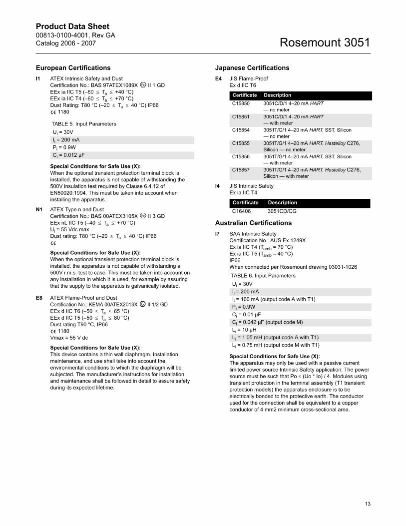
European Certifications
I1 ATEX Intrinsic Safety and Dust
Certification No.: BAS 97ATEX1089X II 1 GD
EEx ia IIC T5 (–60 ≤ Ta ≤ +40 °C)
EEx ia IIC T4 (–60 ≤ Ta ≤ +70 °C)
Dust Rating: T80 °C (–20 ≤ Ta ≤ 40 °C) IP66
1180
Special Conditions for Safe Use (X):
When the optional transient protection terminal block is
installed, the apparatus is not capable of withstanding the
500V insulation test required by Clause 6.4.12 of
EN50020:1994. This must be taken into account when
installing the apparatus.
N1 ATEX Type n and Dust
Certification No.: BAS 00ATEX3105X II 3 GD
EEx nL IIC T5 (–40 ≤ Ta ≤ +70 °C)
Ui = 55 Vdc max
Dust rating: T80 °C (–20 ≤ Ta ≤ 40 °C) IP66
Special Conditions for Safe Use (X):
When the optional transient protection terminal block is
installed, the apparatus is not capable of withstanding a
500V r.m.s. test to case. This must be taken into account on
any installation in which it is used, for example by assuring
that the supply to the apparatus is galvanically isolated.
E8 ATEX Flame-Proof and Dust
Certification No.: KEMA 00ATEX2013X II 1/2 GD
EEx d IIC T6 (–50 ≤ Ta ≤ 65 °C)
EEx d IIC T5 (–50 ≤ Ta ≤ 80 °C)
Dust rating T90 °C, IP66
1180
Vmax = 55 V dc
Special Conditions for Safe Use (X):
This device contains a thin wall diaphragm. Installation,
maintenance, and use shall take into account the
environmental conditions to which the diaphragm will be
subjected. The manufacturer’s instructions for installation
and maintenance shall be followed in detail to assure safety
during its expected lifetime.
Japanese Certifications
E4 JIS Flame-Proof
Ex d IIC T6
I4 JIS Intrinsic Safety
Ex ia IIC T4
Australian Certifications
I7 SAA Intrinsic Safety
Certification No.: AUS Ex 1249X
Ex ia IIC T4 (Tamb = 70 °C)
Ex ia IIC T5 (Tamb = 40 °C)
IP66
When connected per Rosemount drawing 03031-1026
Special Conditions for Safe Use (X):
The apparatus may only be used with a passive current
limited power source Intrinsic Safety application. The power
source must be such that Po ≤ (Uo * Io) / 4. Modules using
transient protection in the terminal assembly (T1 transient
protection models) the apparatus enclosure is to be
electrically bonded to the protective earth. The conductor
used for the connection shall be equivalent to a copper
conductor of 4 mm2 minimum cross-sectional area.
TABLE 5. Input Parameters
Ui = 30V
Ii = 200 mA
Pi = 0.9W
Ci = 0.012 µF
Certificate Description
C15850 3051C/D/1 4–20 mA HART
— no meter
C15851 3051C/D/1 4–20 mA HART
— with meter
C15854 3051T/G/1 4–20 mA HART, SST, Silicon
— no meter
C15855 3051T/G/1 4–20 mA HART, Hastelloy C276,
Silicon — no meter
C15856 3051T/G/1 4–20 mA HART, SST, Silicon
— with meter
C15857 3051T/G/1 4–20 mA HART, Hastelloy C276,
Silicon — with meter
Certificate Description
C16406 3051CD/CG
TABLE 6. Input Parameters
Ui = 30V
Ii = 200 mA
Ii = 160 mA (output code A with T1)
Pi = 0.9W
Ci = 0.01 µF
Ci = 0.042 µF (output code M)
Li = 10 µH
Li = 1.05 mH (output code A with T1)
Li = 0.75 mH (output code M with T1)
13
Product Data Sheet00813-0100-4001, Rev GA
Catalog 2006 - 2007Rosemount 3051
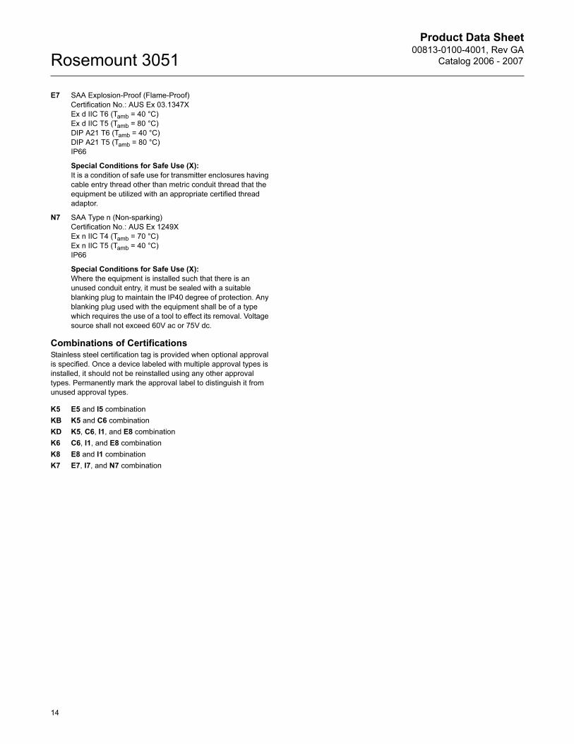
E7 SAA Explosion-Proof (Flame-Proof)
Certification No.: AUS Ex 03.1347X
Ex d IIC T6 (Tamb = 40 °C)
Ex d IIC T5 (Tamb = 80 °C)
DIP A21 T6 (Tamb = 40 °C)
DIP A21 T5 (Tamb = 80 °C)
IP66
Special Conditions for Safe Use (X):
It is a condition of safe use for transmitter enclosures having
cable entry thread other than metric conduit thread that the
equipment be utilized with an appropriate certified thread
adaptor.
N7 SAA Type n (Non-sparking)
Certification No.: AUS Ex 1249X
Ex n IIC T4 (Tamb = 70 °C)
Ex n IIC T5 (Tamb = 40 °C)
IP66
Special Conditions for Safe Use (X):
Where the equipment is installed such that there is an
unused conduit entry, it must be sealed with a suitable
blanking plug to maintain the IP40 degree of protection. Any
blanking plug used with the equipment shall be of a type
which requires the use of a tool to effect its removal. Voltage
source shall not exceed 60V ac or 75V dc.
Combinations of Certifications
Stainless steel certification tag is provided when optional approval
is specified. Once a device labeled with multiple approval types is
installed, it should not be reinstalled using any other approval
types. Permanently mark the approval label to distinguish it from
unused approval types.
K5 E5 and I5 combination
KB K5 and C6 combination
KD K5, C6, I1, and E8 combination
K6 C6, I1, and E8 combination
K8 E8 and I1 combination
K7 E7, I7, and N7 combination
14
Product Data Sheet00813-0100-4001, Rev GA
Catalog 2006 - 2007 Rosemount 3051
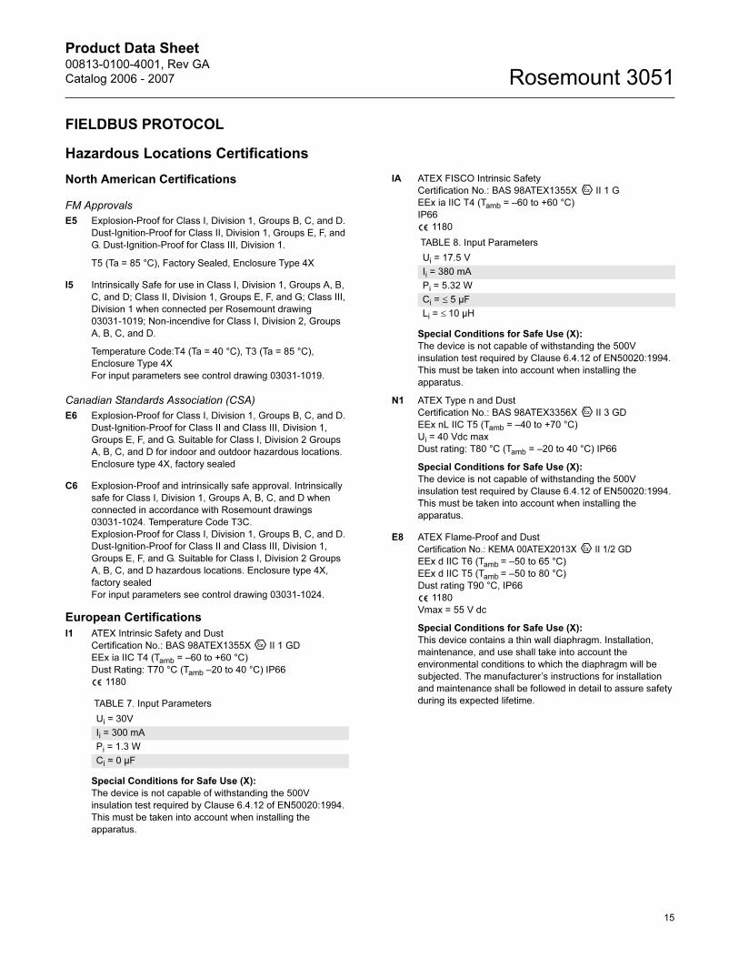
FIELDBUS PROTOCOL
Hazardous Locations Certifications
North American Certifications
FM Approvals
E5 Explosion-Proof for Class I, Division 1, Groups B, C, and D.
Dust-Ignition-Proof for Class II, Division 1, Groups E, F, and
G. Dust-Ignition-Proof for Class III, Division 1.
T5 (Ta = 85 °C), Factory Sealed, Enclosure Type 4X
I5 Intrinsically Safe for use in Class I, Division 1, Groups A, B,
C, and D; Class II, Division 1, Groups E, F, and G; Class III,
Division 1 when connected per Rosemount drawing
03031-1019; Non-incendive for Class I, Division 2, Groups
A, B, C, and D.
Temperature Code:T4 (Ta = 40 °C), T3 (Ta = 85 °C),
Enclosure Type 4X
For input parameters see control drawing 03031-1019.
Canadian Standards Association (CSA)
E6 Explosion-Proof for Class I, Division 1, Groups B, C, and D.
Dust-Ignition-Proof for Class II and Class III, Division 1,
Groups E, F, and G. Suitable for Class I, Division 2 Groups
A, B, C, and D for indoor and outdoor hazardous locations.
Enclosure type 4X, factory sealed
C6 Explosion-Proof and intrinsically safe approval. Intrinsically
safe for Class I, Division 1, Groups A, B, C, and D when
connected in accordance with Rosemount drawings
03031-1024. Temperature Code T3C.
Explosion-Proof for Class I, Division 1, Groups B, C, and D.
Dust-Ignition-Proof for Class II and Class III, Division 1,
Groups E, F, and G. Suitable for Class I, Division 2 Groups
A, B, C, and D hazardous locations. Enclosure type 4X,
factory sealed
For input parameters see control drawing 03031-1024.
European Certifications
I1 ATEX Intrinsic Safety and Dust
Certification No.: BAS 98ATEX1355X II 1 GD
EEx ia IIC T4 (Tamb = –60 to +60 °C)
Dust Rating: T70 °C (Tamb –20 to 40 °C) IP66
1180
Special Conditions for Safe Use (X):
The device is not capable of withstanding the 500V
insulation test required by Clause 6.4.12 of EN50020:1994.
This must be taken into account when installing the
apparatus.
IA ATEX FISCO Intrinsic Safety
Certification No.: BAS 98ATEX1355X II 1 G
EEx ia IIC T4 (Tamb = –60 to +60 °C)
IP66
1180
Special Conditions for Safe Use (X):
The device is not capable of withstanding the 500V
insulation test required by Clause 6.4.12 of EN50020:1994.
This must be taken into account when installing the
apparatus.
N1 ATEX Type n and Dust
Certification No.: BAS 98ATEX3356X II 3 GD
EEx nL IIC T5 (Tamb = –40 to +70 °C)
Ui = 40 Vdc max
Dust rating: T80 °C (Tamb = –20 to 40 °C) IP66
Special Conditions for Safe Use (X):
The device is not capable of withstanding the 500V
insulation test required by Clause 6.4.12 of EN50020:1994.
This must be taken into account when installing the
apparatus.
E8 ATEX Flame-Proof and Dust
Certification No.: KEMA 00ATEX2013X II 1/2 GD
EEx d IIC T6 (Tamb = –50 to 65 °C)
EEx d IIC T5 (Tamb = –50 to 80 °C)
Dust rating T90 °C, IP66
1180
Vmax = 55 V dc
Special Conditions for Safe Use (X):
This device contains a thin wall diaphragm. Installation,
maintenance, and use shall take into account the
environmental conditions to which the diaphragm will be
subjected. The manufacturer’s instructions for installation
and maintenance shall be followed in detail to assure safety
during its expected lifetime. TABLE 7. Input Parameters
Ui = 30V
Ii = 300 mA
Pi = 1.3 W
Ci = 0 µF
TABLE 8. Input Parameters
Ui = 17.5 V
Ii = 380 mA
Pi = 5.32 W
Ci = ≤ 5 µF
Li = ≤ 10 µH
15
Product Data Sheet00813-0100-4001, Rev GA
Catalog 2006 - 2007Rosemount 3051
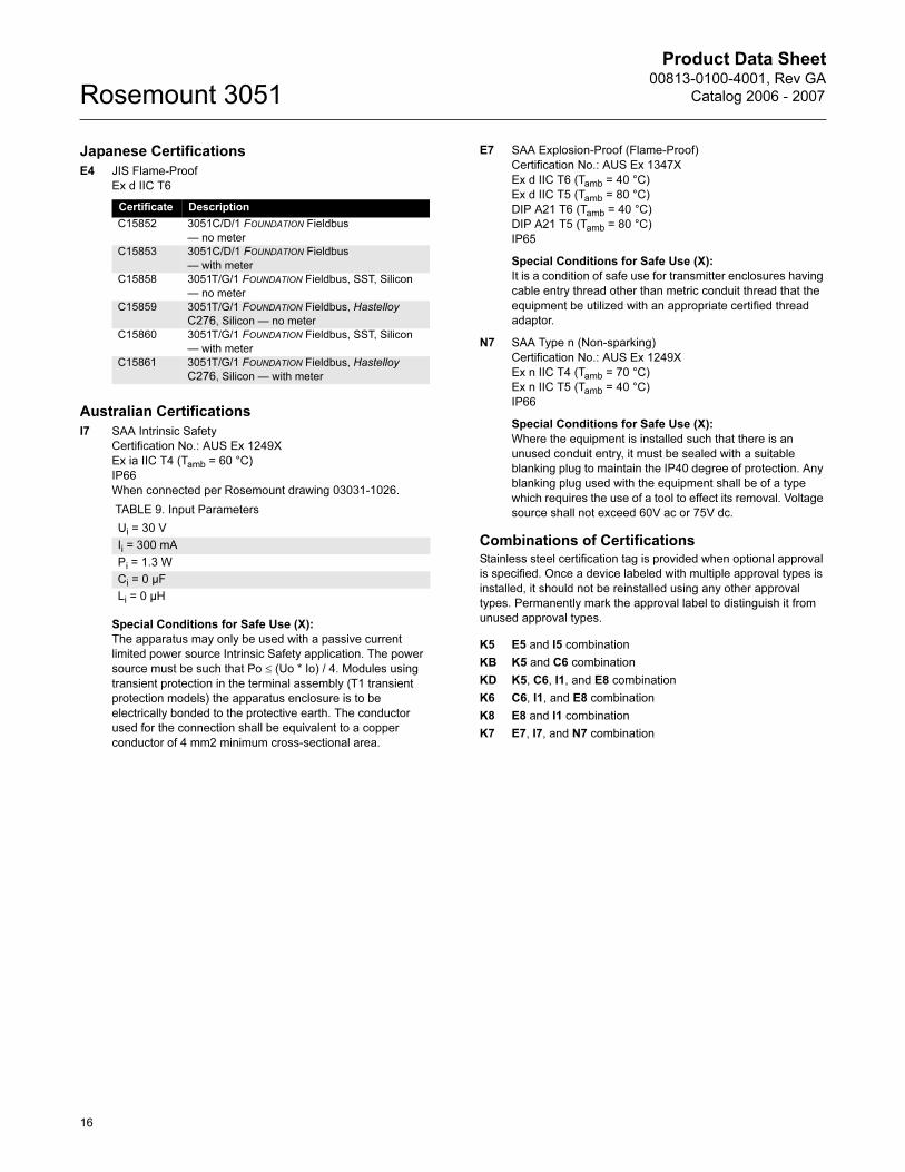
Japanese Certifications
E4 JIS Flame-Proof
Ex d IIC T6
Australian Certifications
I7 SAA Intrinsic Safety
Certification No.: AUS Ex 1249X
Ex ia IIC T4 (Tamb = 60 °C)
IP66
When connected per Rosemount drawing 03031-1026.
Special Conditions for Safe Use (X):
The apparatus may only be used with a passive current
limited power source Intrinsic Safety application. The power
source must be such that Po ≤ (Uo * Io) / 4. Modules using
transient protection in the terminal assembly (T1 transient
protection models) the apparatus enclosure is to be
electrically bonded to the protective earth. The conductor
used for the connection shall be equivalent to a copper
conductor of 4 mm2 minimum cross-sectional area.
E7 SAA Explosion-Proof (Flame-Proof)
Certification No.: AUS Ex 1347X
Ex d IIC T6 (Tamb = 40 °C)
Ex d IIC T5 (Tamb = 80 °C)
DIP A21 T6 (Tamb = 40 °C)
DIP A21 T5 (Tamb = 80 °C)
IP65
Special Conditions for Safe Use (X):
It is a condition of safe use for transmitter enclosures having
cable entry thread other than metric conduit thread that the
equipment be utilized with an appropriate certified thread
adaptor.
N7 SAA Type n (Non-sparking)
Certification No.: AUS Ex 1249X
Ex n IIC T4 (Tamb = 70 °C)
Ex n IIC T5 (Tamb = 40 °C)
IP66
Special Conditions for Safe Use (X):
Where the equipment is installed such that there is an
unused conduit entry, it must be sealed with a suitable
blanking plug to maintain the IP40 degree of protection. Any
blanking plug used with the equipment shall be of a type
which requires the use of a tool to effect its removal. Voltage
source shall not exceed 60V ac or 75V dc.
Combinations of Certifications
Stainless steel certification tag is provided when optional approval
is specified. Once a device labeled with multiple approval types is
installed, it should not be reinstalled using any other approval
types. Permanently mark the approval label to distinguish it from
unused approval types.
K5 E5 and I5 combination
KB K5 and C6 combination
KD K5, C6, I1, and E8 combination
K6 C6, I1, and E8 combination
K8 E8 and I1 combination
K7 E7, I7, and N7 combination
Certificate Description
C15852 3051C/D/1 FOUNDATION Fieldbus
— no meter
C15853 3051C/D/1 FOUNDATION Fieldbus
— with meter
C15858 3051T/G/1 FOUNDATION Fieldbus, SST, Silicon
— no meter
C15859 3051T/G/1 FOUNDATION Fieldbus, Hastelloy
C276, Silicon — no meter
C15860 3051T/G/1 FOUNDATION Fieldbus, SST, Silicon
— with meter
C15861 3051T/G/1 FOUNDATION Fieldbus, Hastelloy
C276, Silicon — with meter
TABLE 9. Input Parameters
Ui = 30 V
Ii = 300 mA
Pi = 1.3 W
Ci = 0 µF
Li = 0 µH
16
Product Data Sheet00813-0100-4001, Rev GA
Catalog 2006 - 2007 Rosemount 3051
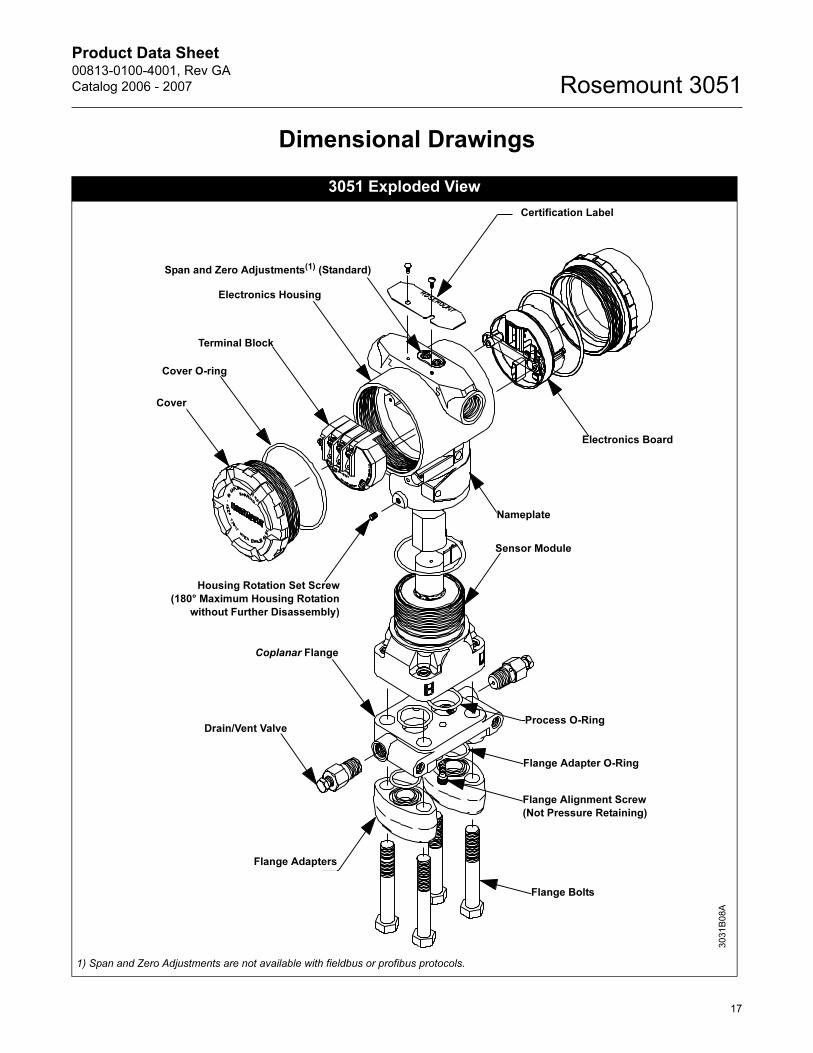
Dimensional Drawings
3051 Exploded View
Certification Label
Span and Zero Adjustments(1) (Standard)
Electronics Housing
Terminal Block
Cover O-ring
Cover
Electronics Board
Nameplate
Sensor Module
Housing Rotation Set Screw
(180° Maximum Housing Rotation
without Further Disassembly)
Flange Alignment Screw
(Not Pressure Retaining)
Flange Bolts
Flange Adapters
Drain/Vent Valve
Coplanar Flange
Flange Adapter O-Ring
Process O-Ring3031B
08A
1) Span and Zero Adjustments are not available with fieldbus or profibus protocols.
17
Product Data Sheet00813-0100-4001, Rev GA
Catalog 2006 - 2007Rosemount 3051
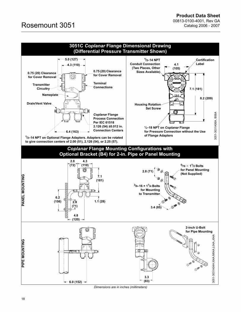
3051C Coplanar Flange Dimensional Drawing (Differential Pressure Transmitter Shown)
Coplanar Flange Mounting Configurations with Optional Bracket (B4) for 2-in. Pipe or Panel Mounting
PA
NE
L M
OU
NT
ING
PIP
E M
OU
NT
ING
Dimensions are in inches (millimeters)
6.4 (163)
1/2–14 NPT on Optional Flange Adapters. Adapters can be rotated
to give connection centers of 2.00 (51), 2.126 (54), or 2.25 (57).
0.75 (20) Clearance
for Cover Removal
Drain/Vent Valve
Transmitter
Circuitry
Nameplate
4.3 (110)
5.0 (127)
0.75 (20) Clearance
for Cover Removal
Terminal
Connections
Coplanar Flange
Process Connection
Per IEC 61518
2.126 (54) ±0.012 in.
Connection Centers¼–18 NPT on Coplanar Flange
for Pressure Connection without the Use
of Flange Adapters
Housing Rotation
Set Screw
7.1
(181
4.1
(105)
Certification
Label
1/2–14 NPT
Conduit
Connection
(Two Places, Other
3051-3
031A
06A
, B
06A
¼–18 NPT on Coplanar Flange
for Pressure Connection without the Use
of Flange Adapters
Housing Rotation
Set Screw
7.1 (181)
8.2 (209)
4.1
(105)
Certification
Label
1/2–14 NPT
Conduit Connection
(Two Places, Other
Sizes Available)
4.3
(110)
2.8
(72)
7.1
(181)
2.8
(71)
6.2
(156)
4.8
(120)
1.1 (28)
5/16 � 11/2 Bolts
for Panel Mounting
(Not Supplied)
3/8–16 × 11/4 Bolts
for Mounting
to Transmitter
2.8 (71)
3.4 (85)
6.0 (152)
3.3
(83)
2-inch U-Bolt
for Pipe Mounting
3051-3
031A
04H
,I04A
,M04A
,L04A
,J04A
18
Product Data Sheet00813-0100-4001, Rev GA
Catalog 2006 - 2007 Rosemount 3051
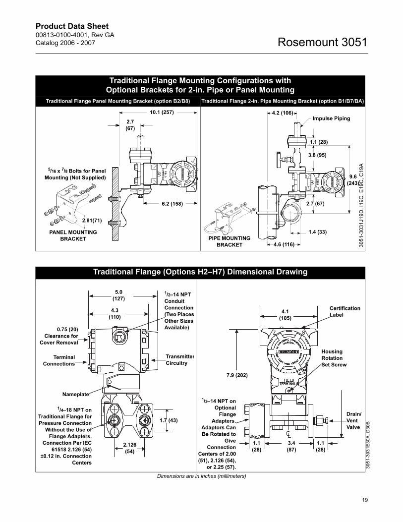
Traditional Flange Mounting Configurations with Optional Brackets for 2-in. Pipe or Panel Mounting
Traditional Flange Panel Mounting Bracket (option B2/B8) Traditional Flange 2-in. Pipe Mounting Bracket (option B1/B7/BA)
10.1 (257)
2.7
(67)
6.2 (158)
PANEL MOUNTING
BRACKET
2.81(71)
5/16 x 7/8 Bolts for Panel
Mounting (Not Supplied)
1.1 (28)
1.4 (33)
4.6 (116)
9.6
(243)
Impulse Piping
3.8 (95)
2.7 (67)
4.2 (106)
PIPE MOUNTING
BRACKET 30
51
-30
31
J1
9D
, I1
9C
, E
19
C,
C1
9A
Traditional Flange (Options H2–H7) Dimensional Drawing
Dimensions are in inches (millimeters)
5.0
(127)
4.3
(110)
0.75 (20)
Clearance for
Cover Removal
Transmitter
Circuitry Terminal
Connections
Nameplate
1/2–14 NPT
Conduit
Connection
(Two Places
Other Sizes
Available)
1.7 (43)
2.126
(54)
1/4–18 NPT on
Traditional Flange for
Pressure Connection
Without the Use of
Flange Adapters.
Connection Per IEC
61518 2.126 (54)
±0.12 in. Connection
Centers
3051-3
031E
30A
, D
30B
Certification
Label 4.1
(105)
7.9 (202)
1.1
(28)
Housing
Rotation
Set Screw
3.4
(87)
1.1
(28)
Drain/
Vent
Valve
1/2–14 NPT on
Optional
Flange
Adapters.
Adaptors Can
Be Rotated to
Give
Connection
Centers of 2.00
(51), 2.126 (54),
or 2.25 (57).
19
Product Data Sheet00813-0100-4001, Rev GA
Catalog 2006 - 2007Rosemount 3051
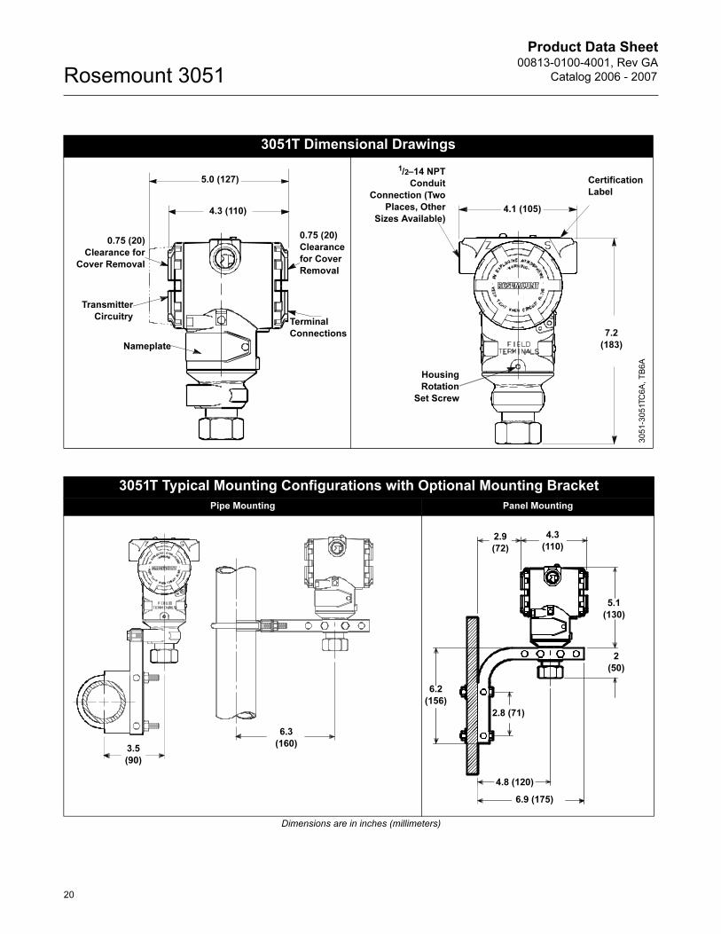
3051T Dimensional Drawings
Terminal
Connections
Transmitter
Circuitry
Nameplate
5.0 (127)
4.3 (110)
0.75 (20)
Clearance for
Cover Removal
0.75 (20)
Clearance
for Cover
Removal
1/2–14 NPT
Conduit
Connection (Two
Places, Other
Sizes Available)
Certification
Label
Housing
Rotation
Set Screw
7.2
(183)
4.1 (105)
3051-3
051TC
6A
, T
B6A
3051T Typical Mounting Configurations with Optional Mounting Bracket
Pipe Mounting Panel Mounting
Dimensions are in inches (millimeters)
3.5
(90)
6.3
(160)
2
(50)
6.2
(156)
2.9
(72)
4.3
(110)
2.8 (71)
4.8 (120)
6.9 (175)
5.1
(130)
20
Product Data Sheet00813-0100-4001, Rev GA
Catalog 2006 - 2007 Rosemount 3051
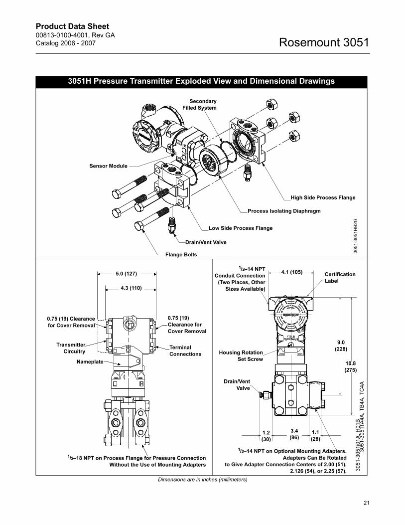
3051H Pressure Transmitter Exploded View and Dimensional Drawings
Dimensions are in inches (millimeters)
Process Isolating Diaphragm
High Side Process Flange
Low Side Process Flange
Drain/Vent Valve
Flange Bolts
Secondary
Filled System
Sensor Module
3051-3
051H
B2G
5.0 (127)
4.3 (110)
0.75 (19) Clearance
for Cover Removal
Transmitter
Circuitry
Nameplate
Terminal
Connections
0.75 (19)
Clearance for
Cover Removal
1/2–18 NPT on Process Flange for Pressure Connection
Without the Use of Mounting Adapters
Drain/Vent
Valve
Housing Rotation
Set Screw
1.2
(30)
1.1
(28)
3.4
(86)
4.1 (105)
10.8
(275)
9.0
(228)
1/2–14 NPT on Optional Mounting Adapters.
Adapters Can Be Rotated
to Give Adapter Connection Centers of 2.00 (51),
2.126 (54), or 2.25 (57).
Certification
Label
1/2–14 NPT
Conduit Connection
(Two Places, Other
Sizes Available)
30
51
-30
51
i01
A,
H0
1B
3
05
1-3
05
1TA
4A
, T
B4
A,
TC
4A
21
Product Data Sheet00813-0100-4001, Rev GA
Catalog 2006 - 2007Rosemount 3051
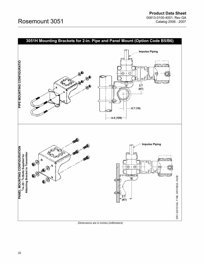
3051H Mounting Brackets for 2-in. Pipe and Panel Mount (Option Code B5/B6)
PIP
E M
OU
NT
ING
CO
NF
IGU
RA
TIO
PA
NE
L M
OU
NT
ING
CO
NF
IGU
RA
TIO
N7/16–
20�
3/4
Bo
lts
Su
pp
lie
d f
or
Att
ac
hin
g B
rac
ke
t to
Tra
ns
mit
ter
Dimensions are in inches (millimeters)
Impulse Piping
2.7
(67)
0.7 (16)
4.4 (109)
Impulse Piping
2.7
(67)
3051-3
031G
19A
, F
19B
, 3
05
1H
B3
A, H
A3
B
22
Product Data Sheet00813-0100-4001, Rev GA
Catalog 2006 - 2007 Rosemount 3051
23
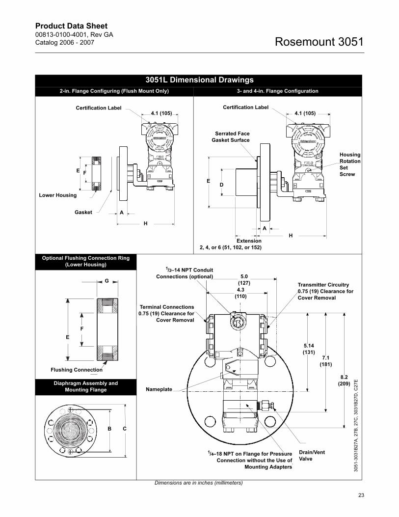
3051L Dimensional Drawings
2-in. Flange Configuring (Flush Mount Only) 3- and 4-in. Flange Configuration
Optional Flushing Connection Ring
(Lower Housing)
Diaphragm Assembly and
Mounting Flange
Dimensions are in inches (millimeters)
Certification Label
Gasket
Lower Housing
A
4.1 (105)
E F
H
Serrated Face
Gasket Surface
Certification Label
A
Housing
Rotation
Set
Screw
Extension
2, 4, or 6 (51, 102, or 152)
E
4.1 (105)
D
H
1/2–14 NPT Conduit
Connections (optional) 5.0
(127)
Terminal Connections
0.75 (19) Clearance for
Cover Removal
Nameplate
Drain/Vent
Valve
5.14
(131)
8.2
(209)
4.3
(110)
1/4–18 NPT on Flange for Pressure
Connection without the Use of
Mounting Adapters
7.1
(181)
Transmitter Circuitry
0.75 (19) Clearance for
Cover Removal
3051-3
031B
27A
, 27B
, 27C
, 3031B
27D
, C
27E
Flushing Connection
E
F
G
CB
Product Data Sheet00813-0100-4001, Rev GA
Catalog 2006 - 2007Rosemount 3051
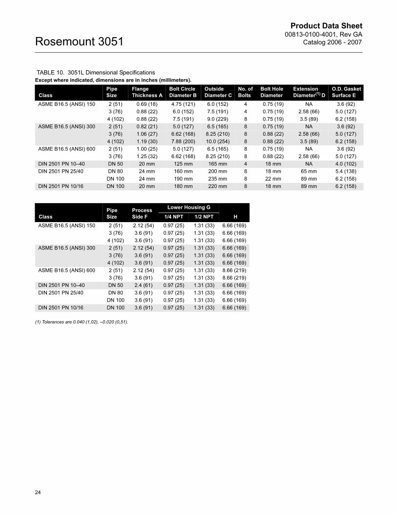
(1) Tolerances are 0.040 (1,02), –0.020 (0,51).
TABLE 10. 3051L Dimensional Specifications
Except where indicated, dimensions are in inches (millimeters).
Class
Pipe
Size
Flange
Thickness A
Bolt Circle
Diameter B
Outside
Diameter C
No. of
Bolts
Bolt Hole
Diameter
Extension
Diameter(1) D
O.D. Gasket
Surface E
ASME B16.5 (ANSI) 150 2 (51) 0.69 (18) 4.75 (121) 6.0 (152) 4 0.75 (19) NA 3.6 (92)
3 (76) 0.88 (22) 6.0 (152) 7.5 (191) 4 0.75 (19) 2.58 (66) 5.0 (127)
4 (102) 0.88 (22) 7.5 (191) 9.0 (229) 8 0.75 (19) 3.5 (89) 6.2 (158)
ASME B16.5 (ANSI) 300 2 (51) 0.82 (21) 5.0 (127) 6.5 (165) 8 0.75 (19) NA 3.6 (92)
3 (76) 1.06 (27) 6.62 (168) 8.25 (210) 8 0.88 (22) 2.58 (66) 5.0 (127)
4 (102) 1.19 (30) 7.88 (200) 10.0 (254) 8 0.88 (22) 3.5 (89) 6.2 (158)
ASME B16.5 (ANSI) 600 2 (51) 1.00 (25) 5.0 (127) 6.5 (165) 8 0.75 (19) NA 3.6 (92)
3 (76) 1.25 (32) 6.62 (168) 8.25 (210) 8 0.88 (22) 2.58 (66) 5.0 (127)
DIN 2501 PN 10–40 DN 50 20 mm 125 mm 165 mm 4 18 mm NA 4.0 (102)
DIN 2501 PN 25/40 DN 80 24 mm 160 mm 200 mm 8 18 mm 65 mm 5.4 (138)
DN 100 24 mm 190 mm 235 mm 8 22 mm 89 mm 6.2 (158)
DIN 2501 PN 10/16 DN 100 20 mm 180 mm 220 mm 8 18 mm 89 mm 6.2 (158)
Class
Pipe
Size
Process
Side F
Lower Housing G
H1/4 NPT 1/2 NPT
ASME B16.5 (ANSI) 150 2 (51) 2.12 (54) 0.97 (25) 1.31 (33) 6.66 (169)
3 (76) 3.6 (91) 0.97 (25) 1.31 (33) 6.66 (169)
4 (102) 3.6 (91) 0.97 (25) 1.31 (33) 6.66 (169)
ASME B16.5 (ANSI) 300 2 (51) 2.12 (54) 0.97 (25) 1.31 (33) 6.66 (169)
3 (76) 3.6 (91) 0.97 (25) 1.31 (33) 6.66 (169)
4 (102) 3.6 (91) 0.97 (25) 1.31 (33) 6.66 (169)
ASME B16.5 (ANSI) 600 2 (51) 2.12 (54) 0.97 (25) 1.31 (33) 8.66 (219)
3 (76) 3.6 (91) 0.97 (25) 1.31 (33) 8.66 (219)
DIN 2501 PN 10–40 DN 50 2.4 (61) 0.97 (25) 1.31 (33) 6.66 (169)
DIN 2501 PN 25/40 DN 80 3.6 (91) 0.97 (25) 1.31 (33) 6.66 (169)
DN 100 3.6 (91) 0.97 (25) 1.31 (33) 6.66 (169)
DIN 2501 PN 10/16 DN 100 3.6 (91) 0.97 (25) 1.31 (33) 6.66 (169)
24
Product Data Sheet00813-0100-4001, Rev GA
Catalog 2006 - 2007 Rosemount 3051
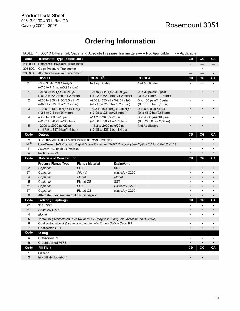
Ordering Information
TABLE 11. 3051C Differential, Gage, and Absolute Pressure Transmitters — = Not Applicable • = Applicable
Model Transmitter Type (Select One) CD CG CA
3051CD Differential Pressure Transmitter • — —
3051CG Gage Pressure Transmitter — • —
3051CA Absolute Pressure Transmitter — — •
3051CD 3051CG(1) 3051CA CD CG CA
0(2) –3 to 3 inH2O/0.1 inH2O
(–7,5 to 7,5 mbar/0,25 mbar)
Not Applicable Not Applicable • — •
1 –25 to 25 inH2O/0.5 inH2O
(–62,2 to 62,2 mbar/1,2 mbar)
–25 to 25 inH2O/0.5 inH2O
(–62,2 to 62,2 mbar/1,2 mbar)
0 to 30 psia/0.3 psia
(0 to 2,1 bar/20,7 mbar)
• • •
2 –250 to 250 inH2O/2.5 inH2O
(–623 to 623 mbar/6,2 mbar)
–250 to 250 inH2O/2.5 inH2O
(–623 to 623 mbar/6,2 mbar)
0 to 150 psia/1.5 psia
(0 to 10,3 bar/0,1 bar)
• • •
3 –1000 to 1000 inH2O/10 inH2O
(–2,5 to 2,5 bar/25 mbar)
–393 to 1000inH2O/10in H2O
(–0,98 to 2,5 bar/25 mbar)
0 to 800 psia/8 psia
(0 to 55,2 bar/0,55 bar)
• • •
4 –300 to 300 psi/3 psi
(–20,7 to 20,7 bar/0,2 bar)
–14.2 to 300 psi/3 psi
(–0,98 to 20,7 bar/0,2 bar)
0 to 4000 psia/40 psia
(0 to 275,8 bar/2,8 bar)
• • •
5 –2000 to 2000 psi/20 psi
(–137,9 to137,9 bar/1,4 bar)
–14.2 to 2000 psig/20 psi
(–0,98 to 137,9 bar/1,4 bar)
Not Applicable • • —
Code Output CD CG CA
A 4–20 mA with Digital Signal Based on HART Protocol • • •
M(3)Low-Power, 1–5 V dc with Digital Signal Based on HART Protocol (See Option C2 for 0.8–3.2 V dc) • • •
F FOUNDATION fieldbus Protocol • • •
W Profibus — PA • • •
Code Materials of Construction CD CG CA
Process Flange Type Flange Material Drain/Vent
2 Coplanar SST SST • • •
3(4) Coplanar Alloy C Hastelloy C276 • • •
4 Coplanar Monel Monel • • •
5 Coplanar Plated CS SST • • •
7(4) Coplanar SST Hastelloy C276 • • •
8(4) Coplanar Plated CS Hastelloy C276 • • •
0 Alternate Flange—See Options on page 26 • • •
Code Isolating Diaphragm CD CG CA
2(4) 316L SST • • •
3(4) Hastelloy C276 • • •
4 Monel • • •
5 Tantalum (Available on 3051CD and CG, Ranges 2–5 only. Not available on 3051CA) • • —
6 Gold-plated Monel (Use in combination with O-ring Option Code B.) • • •
7 Gold-plated SST • • •
Code O-ring
A Glass-filled PTFE • • •
B Graphite-filled PTFE • • •
Code Fill Fluid CD CG CA
1 Silicone • • •
2 Inert fill (Halocarbon) • • —
25
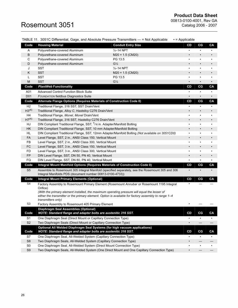
Product Data Sheet00813-0100-4001, Rev GA
Catalog 2006 - 2007Rosemount 3051
Code Housing Material Conduit Entry Size CD CG CA
A Polyurethane-covered Aluminum ½–14 NPT • • •
B Polyurethane-covered Aluminum M20 × 1.5 (CM20) • • •
C Polyurethane-covered Aluminum PG 13.5 • • •
D Polyurethane-covered Aluminum G½ • • •
J SST ½–14 NPT • • •
K SST M20 × 1.5 (CM20) • • •
L SST PG 13.5 • • •
M SST G½ • • •
Code PlantWeb Functionality CD CG CA
A01 Advanced Control Function Block Suite • • •
D01 FOUNDATION fieldbus Diagnostics Suite • • •
Code Alternate Flange Options (Requires Materials of Construction Code 0) CD CG CA
H2 Traditional Flange, 316 SST, SST Drain/Vent • • •
H3(4) Traditional Flange, Alloy C, Hastelloy C276 Drain/Vent • • •
H4 Traditional Flange, Monel, Monel Drain/Vent • • •
H7(4) Traditional Flange, 316 SST, Hastelloy C276 Drain/Vent • • •
HJ DIN Compliant Traditional Flange, SST, 7/16 in. Adapter/Manifold Bolting • • •
HK DIN Compliant Traditional Flange, SST, 10 mm Adapter/Manifold Bolting • • •
HL DIN Compliant Traditional Flange, SST, 12mm Adapter/Manifold Bolting (Not available on 3051CD0) • • •
FA Level Flange, SST, 2 in., ANSI Class 150, Vertical Mount • • •
FB Level Flange, SST, 2 in., ANSI Class 300, Vertical Mount • • •
FC Level Flange, SST, 3 in., ANSI Class 150, Vertical Mount • • •
FD Level Flange, SST, 3 in., ANSI Class 300, Vertical Mount • • •
FP DIN Level Flange, SST, DN 50, PN 40, Vertical Mount • • •
FQ DIN Level Flange, SST, DN 80, PN 40, Vertical Mount • • •
Code Integral Mount Manifold Options (Requires Materials of Construction Code 0) CD CG CA
S5 Assemble to Rosemount 305 Integral Manifold (specified separately, see the Rosemount 305 and 306
Integral Manifolds PDS (document number 00813-0100-4733))
• • •
Code Integral Mount Primary Elements (Optional) CD CG CA
S4 Factory Assembly to Rosemount Primary Element (Rosemount Annubar or Rosemount 1195 Integral
Orifice)
(With the primary element installed, the maximum operating pressure will equal the lesser of
either the transmitter or the primary element. Option is available for factory assembly to range 1–4
transmitters only)
• — —
S3 Factory Assembly to Rosemount 405 Primary Element • — —
Code
Diaphragm Seal Assemblies (Optional)
NOTE: Standard flange and adapter bolts are austenitic 316 SST. CD CG CA
S1 One Diaphragm Seal (Direct Mount or Capillary Connection Type) • • •
S2 Two Diaphragm Seals (Direct Mount or Capillary Connection Type) • — —
Code
Optional All Welded Diaphragm Seal Systems (for high vacuum applications)
NOTE: Standard flange and adapter bolts are austenitic 316 SST. CD CG CA
S7 One Diaphragm Seal, All-Welded System (Capillary Connection Type) • • •
S8 Two Diaphragm Seals, All-Welded System (Capillary Connection Type) • — —
S0 One Diaphragm Seal, All-Welded System (Direct Mount Connection Type) • • •
S9 Two Diaphragm Seals, All-Welded System (One Direct Mount and One Capillary Connection Type) • — —
TABLE 11. 3051C Differential, Gage, and Absolute Pressure Transmitters — = Not Applicable • = Applicable
26
Product Data Sheet00813-0100-4001, Rev GA
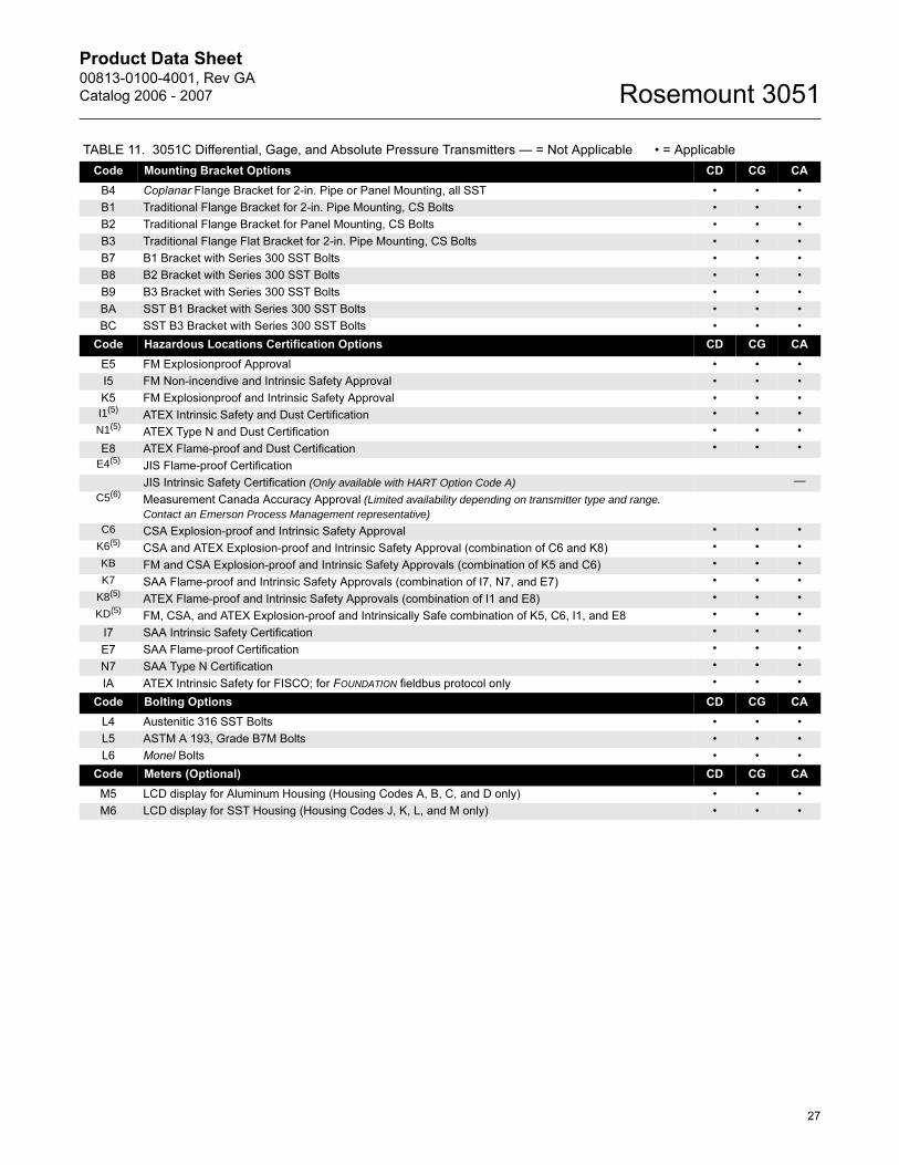
Catalog 2006 - 2007 Rosemount 3051
Code Mounting Bracket Options CD CG CA
B4 Coplanar Flange Bracket for 2-in. Pipe or Panel Mounting, all SST • • •
B1 Traditional Flange Bracket for 2-in. Pipe Mounting, CS Bolts • • •
B2 Traditional Flange Bracket for Panel Mounting, CS Bolts • • •
B3 Traditional Flange Flat Bracket for 2-in. Pipe Mounting, CS Bolts • • •
B7 B1 Bracket with Series 300 SST Bolts • • •
B8 B2 Bracket with Series 300 SST Bolts • • •
B9 B3 Bracket with Series 300 SST Bolts • • •
BA SST B1 Bracket with Series 300 SST Bolts • • •
BC SST B3 Bracket with Series 300 SST Bolts • • •
Code Hazardous Locations Certification Options CD CG CA
E5 FM Explosionproof Approval • • •
I5 FM Non-incendive and Intrinsic Safety Approval • • •
K5 FM Explosionproof and Intrinsic Safety Approval • • •
I1(5)ATEX Intrinsic Safety and Dust Certification • • •
N1(5)ATEX Type N and Dust Certification • • •
E8 ATEX Flame-proof and Dust Certification • • •
E4(5)JIS Flame-proof Certification
JIS Intrinsic Safety Certification (Only available with HART Option Code A) —
C5(6)Measurement Canada Accuracy Approval (Limited availability depending on transmitter type and range. Contact an Emerson Process Management representative)
C6 CSA Explosion-proof and Intrinsic Safety Approval • • •
K6(5)CSA and ATEX Explosion-proof and Intrinsic Safety Approval (combination of C6 and K8) • • •
KB FM and CSA Explosion-proof and Intrinsic Safety Approvals (combination of K5 and C6) • • •
K7 SAA Flame-proof and Intrinsic Safety Approvals (combination of I7, N7, and E7) • • •
K8(5)ATEX Flame-proof and Intrinsic Safety Approvals (combination of I1 and E8) • • •
KD(5)FM, CSA, and ATEX Explosion-proof and Intrinsically Safe combination of K5, C6, I1, and E8 • • •
I7 SAA Intrinsic Safety Certification • • •
E7 SAA Flame-proof Certification • • •
N7 SAA Type N Certification • • •
IA ATEX Intrinsic Safety for FISCO; for FOUNDATION fieldbus protocol only • • •
Code Bolting Options CD CG CA
L4 Austenitic 316 SST Bolts • • •
L5 ASTM A 193, Grade B7M Bolts • • •
L6 Monel Bolts • • •
Code Meters (Optional) CD CG CA
M5 LCD display for Aluminum Housing (Housing Codes A, B, C, and D only) • • •
M6 LCD display for SST Housing (Housing Codes J, K, L, and M only) • • •
TABLE 11. 3051C Differential, Gage, and Absolute Pressure Transmitters — = Not Applicable • = Applicable
27
Product Data Sheet00813-0100-4001, Rev GA
Catalog 2006 - 2007Rosemount 3051
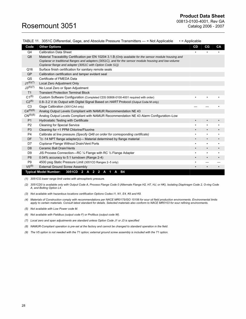
Code Other Options CD CG CA
Q4 Calibration Data Sheet • • •
Q8 Material Traceability Certification per EN 10204 3.1.B (Only available for the sensor module housing and Coplanar or traditional flanges and adapters (3051C), and for the sensor module housing and low-volume Coplanar flange and adapter (3051C with Option Code S1))
Q16 Surface finish certification for sanitary remote seals
QP Calibration certification and tamper evident seal
QS Certificate of FMEDA Data
J1(6)(7) Local Zero Adjustment Only
J3(6)(7) No Local Zero or Span Adjustment
T1 Transient Protection Terminal Block
C1(6) Custom Software Configuration (Completed CDS 00806-0100-4001 required with order) • • •
C2(6) 0.8–3.2 V dc Output with Digital Signal Based on HART Protocol (Output Code M only)
C3 Gage Calibration (3051CA4 only) — — •
C4(6)(8) Analog Output Levels Compliant with NAMUR Recommendation NE 43
CN(6)(8) Analog Output Levels Compliant with NAMUR Recommendation NE 43 Alarm Configuration–Low
P1 Hydrostatic Testing with Certificate • • •
P2 Cleaning for Special Service • • •
P3 Cleaning for <1 PPM Chlorine/Fluorine • • •
P4 Calibrate at line pressure (Specify Q48 on order for corresponding certificate) • • •
DF 1/2 -14 NPT flange adapter(s)— Material determined by flange material • • •
D7 Coplanar Flange Without Drain/Vent Ports • • •
D8 Ceramic Ball Drain/Vents • • •
D9 JIS Process Connection—RC ¼ Flange with RC ½ Flange Adapter • • •
P8 0.04% accuracy to 5:1 turndown (Range 2-4) • • •
P9 4500 psig Static Pressure Limit (3051CD Ranges 2–5 only) • — —
V5(9) External Ground Screw Assembly • • •
Typical Model Number: 3051CD 2 A 2 2 A 1 A B4
(1) 3051CG lower range limit varies with atmospheric pressure.
(2) 3051CD0 is available only with Output Code A, Process Flange Code 0 (Alternate Flange H2, H7, HJ, or HK), Isolating Diaphragm Code 2, O-ring Code A, and Bolting Option L4.
(3) Not available with hazardous locations certification Options Codes I1, N1, E4, K6 and K8.
(4) Materials of Construction comply with recommendations per NACE MR0175/ISO 15156 for sour oil field production environments. Environmental limits apply to certain materials. Consult latest standard for details. Selected materials also conform to NACE MR0103 for sour refining environments.
(5) Not available with Low Power code M.
(6) Not available with Fieldbus (output code F) or Profibus (output code W).
(7) Local zero and span adjustments are standard unless Option Code J1 or J3 is specified
(8) NAMUR-Compliant operation is pre-set at the factory and cannot be changed to standard operation in the field.
(9) The V5 option is not needed with the T1 option; external ground screw assembly is included with the T1 option.
TABLE 11. 3051C Differential, Gage, and Absolute Pressure Transmitters — = Not Applicable • = Applicable
28
Product Data Sheet00813-0100-4001, Rev GA
Catalog 2006 - 2007 Rosemount 3051
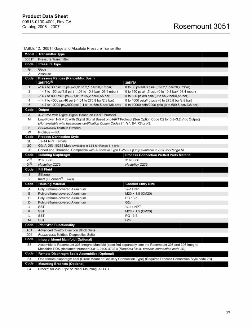
TABLE 12. 3051T Gage and Absolute Pressure Transmitter
Model Transmitter Type
3051T Pressure Transmitter
Code Pressure Type
G Gage
A Absolute
Code Pressure Ranges (Range/Min. Span)
3051TG(1) 3051TA
1 –14.7 to 30 psi/0.3 psi (–1,01 to 2,1 bar/20,7 mbar) 0 to 30 psia/0.3 psia (0 to 2,1 bar/20,7 mbar)
2 –14.7 to 150 psi/1.5 psi (–1,01 to 10,3 bar/103,4 mbar) 0 to 150 psia/1.5 psia (0 to 10,3 bar/103,4 mbar)
3 –14.7 to 800 psi/8 psi (–1,01 to 55,2 bar/0,55 bar) 0 to 800 psia/8 psia (0 to 55,2 bar/0,55 bar)
4 –14.7 to 4000 psi/40 psi (–1,01 to 275,8 bar/2,8 bar) 0 to 4000 psia/40 psia (0 to 275,8 bar/2,8 bar)
5 –14.7 to 10000 psi/2000 psi (–1,01 to 689,5 bar/138 bar) 0 to 10000 psia/2000 psia (0 to 689,5 bar/138 bar)
Code Output
A 4–20 mA with Digital Signal Based on HART Protocol
M Low-Power 1–5 V dc with Digital Signal Based on HART Protocol (See Option Code C2 for 0.8–3.2 V dc Output)
(Not available with hazardous certification Option Codes I1, N1, E4, K6 or K8)
F FOUNDATION fieldbus Protocol
W Profibus — PA
Code Process Connection Style
2B 1/2–14 NPT Female
2C G½ A DIN 16288 Male (Available in SST for Range 1–4 only)
2F Coned and Threaded, Compatible with Autoclave Type F-250-C (Only available in SST for Range 5)
Code Isolating Diaphragm Process Connection Wetted Parts Material
2(2) 316L SST 316L SST
3(2) Hastelloy C276 Hastelloy C276
Code Fill Fluid
1 Silicone
2 Inert (Fluorinert® FC-43)
Code Housing Material Conduit Entry Size
A Polyurethane-covered Aluminum ½–14 NPT
B Polyurethane-covered Aluminum M20 × 1.5 (CM20)
C Polyurethane-covered Aluminum PG 13.5
D Polyurethane-covered Aluminum G½
J SST ½–14 NPT
K SST M20 × 1.5 (CM20)
L SST PG 13.5
M SST G½
Code PlantWeb Functionality
A01 Advanced Control Function Block Suite
D01 FOUNDATION fieldbus Diagnostics Suite
Code Integral Mount Manifold (Optional)
S5 Assemble to Rosemount 306 Integral Manifold (specified separately, see the Rosemount 305 and 306 Integral
Manifolds PDS (document number 00813-0100-4733)) (Requires 1/2-in. process connection code 2B)
Code Remote Diaphragm Seals Assemblies (Optional)
S1 One remote diaphragm seal (Direct Mount or Capillary Connection Type) (Requires Process Connection Style code 2B)
Code Mounting Brackets (Optional)
B4 Bracket for 2-in. Pipe or Panel Mounting, All SST
29
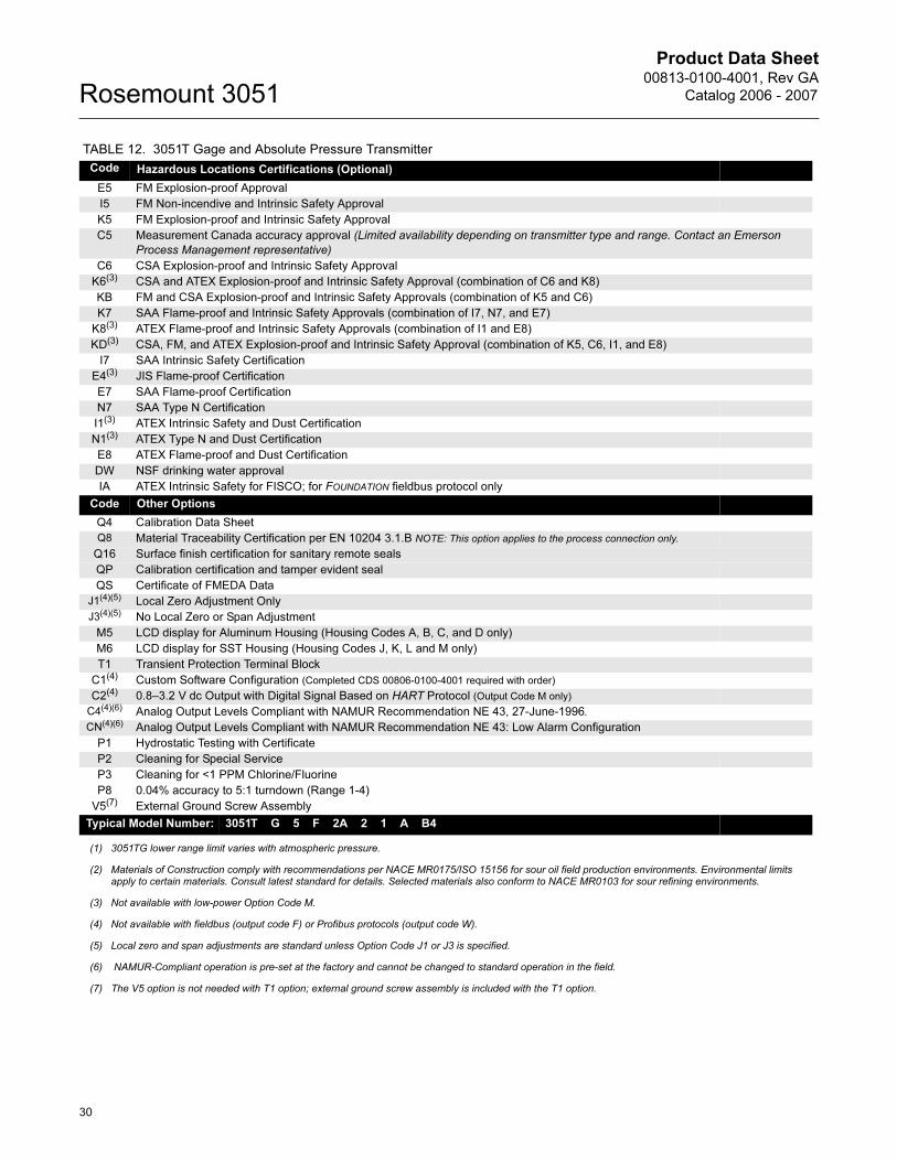
Product Data Sheet00813-0100-4001, Rev GA
Catalog 2006 - 2007Rosemount 3051
Code Hazardous Locations Certifications (Optional)
E5 FM Explosion-proof Approval
I5 FM Non-incendive and Intrinsic Safety Approval
K5 FM Explosion-proof and Intrinsic Safety Approval
C5 Measurement Canada accuracy approval (Limited availability depending on transmitter type and range. Contact an Emerson
Process Management representative)
C6 CSA Explosion-proof and Intrinsic Safety Approval
K6(3) CSA and ATEX Explosion-proof and Intrinsic Safety Approval (combination of C6 and K8)
KB FM and CSA Explosion-proof and Intrinsic Safety Approvals (combination of K5 and C6)
K7 SAA Flame-proof and Intrinsic Safety Approvals (combination of I7, N7, and E7)
K8(3) ATEX Flame-proof and Intrinsic Safety Approvals (combination of I1 and E8)
KD(3) CSA, FM, and ATEX Explosion-proof and Intrinsic Safety Approval (combination of K5, C6, I1, and E8)
I7 SAA Intrinsic Safety Certification
E4(3) JIS Flame-proof Certification
E7 SAA Flame-proof Certification
N7 SAA Type N Certification
I1(3) ATEX Intrinsic Safety and Dust Certification
N1(3) ATEX Type N and Dust Certification
E8 ATEX Flame-proof and Dust Certification
DW NSF drinking water approval
IA ATEX Intrinsic Safety for FISCO; for FOUNDATION fieldbus protocol only
Code Other Options
Q4 Calibration Data Sheet
Q8 Material Traceability Certification per EN 10204 3.1.B NOTE: This option applies to the process connection only.
Q16 Surface finish certification for sanitary remote seals
QP Calibration certification and tamper evident seal
QS Certificate of FMEDA Data
J1(4)(5) Local Zero Adjustment Only
J3(4)(5) No Local Zero or Span Adjustment
M5 LCD display for Aluminum Housing (Housing Codes A, B, C, and D only)
M6 LCD display for SST Housing (Housing Codes J, K, L and M only)
T1 Transient Protection Terminal Block
C1(4) Custom Software Configuration (Completed CDS 00806-0100-4001 required with order)
C2(4) 0.8–3.2 V dc Output with Digital Signal Based on HART Protocol (Output Code M only)
C4(4)(6) Analog Output Levels Compliant with NAMUR Recommendation NE 43, 27-June-1996.
CN(4)(6) Analog Output Levels Compliant with NAMUR Recommendation NE 43: Low Alarm Configuration
P1 Hydrostatic Testing with Certificate
P2 Cleaning for Special Service
P3 Cleaning for <1 PPM Chlorine/Fluorine
P8 0.04% accuracy to 5:1 turndown (Range 1-4)
V5(7) External Ground Screw Assembly
Typical Model Number: 3051T G 5 F 2A 2 1 A B4
(1) 3051TG lower range limit varies with atmospheric pressure.
(2) Materials of Construction comply with recommendations per NACE MR0175/ISO 15156 for sour oil field production environments. Environmental limits apply to certain materials. Consult latest standard for details. Selected materials also conform to NACE MR0103 for sour refining environments.
(3) Not available with low-power Option Code M.
(4) Not available with fieldbus (output code F) or Profibus protocols (output code W).
(5) Local zero and span adjustments are standard unless Option Code J1 or J3 is specified.
(6) NAMUR-Compliant operation is pre-set at the factory and cannot be changed to standard operation in the field.
(7) The V5 option is not needed with T1 option; external ground screw assembly is included with the T1 option.
TABLE 12. 3051T Gage and Absolute Pressure Transmitter
30
Product Data Sheet00813-0100-4001, Rev GA
Catalog 2006 - 2007 Rosemount 3051
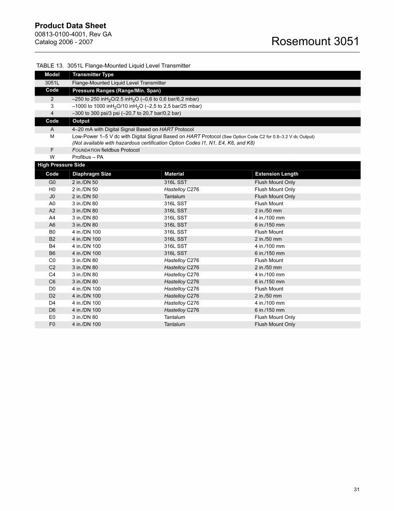
TABLE 13. 3051L Flange-Mounted Liquid Level Transmitter
Model Transmitter Type
3051L Flange-Mounted Liquid Level Transmitter
Code Pressure Ranges (Range/Min. Span)
2 –250 to 250 inH2O/2.5 inH2O (–0,6 to 0,6 bar/6,2 mbar)
3 –1000 to 1000 inH2O/10 inH2O (–2,5 to 2,5 bar/25 mbar)
4 –300 to 300 psi/3 psi (–20,7 to 20,7 bar/0,2 bar)
Code Output
A 4–20 mA with Digital Signal Based on HART Protocol
M Low-Power 1–5 V dc with Digital Signal Based on HART Protocol (See Option Code C2 for 0.8–3.2 V dc Output)
(Not available with hazardous certification Option Codes I1, N1, E4, K6, and K8)
F FOUNDATION fieldbus Protocol
W Profibus – PA
High Pressure Side
Code Diaphragm Size Material Extension Length
G0 2 in./DN 50 316L SST Flush Mount Only
H0 2 in./DN 50 Hastelloy C276 Flush Mount Only
J0 2 in./DN 50 Tantalum Flush Mount Only
A0 3 in./DN 80 316L SST Flush Mount
A2 3 in./DN 80 316L SST 2 in./50 mm
A4 3 in./DN 80 316L SST 4 in./100 mm
A6 3 in./DN 80 316L SST 6 in./150 mm
B0 4 in./DN 100 316L SST Flush Mount
B2 4 in./DN 100 316L SST 2 in./50 mm
B4 4 in./DN 100 316L SST 4 in./100 mm
B6 4 in./DN 100 316L SST 6 in./150 mm
C0 3 in./DN 80 Hastelloy C276 Flush Mount
C2 3 in./DN 80 Hastelloy C276 2 in./50 mm
C4 3 in./DN 80 Hastelloy C276 4 in./100 mm
C6 3 in./DN 80 Hastelloy C276 6 in./150 mm
D0 4 in./DN 100 Hastelloy C276 Flush Mount
D2 4 in./DN 100 Hastelloy C276 2 in./50 mm
D4 4 in./DN 100 Hastelloy C276 4 in./100 mm
D6 4 in./DN 100 Hastelloy C276 6 in./150 mm
E0 3 in./DN 80 Tantalum Flush Mount Only
F0 4 in./DN 100 Tantalum Flush Mount Only
31
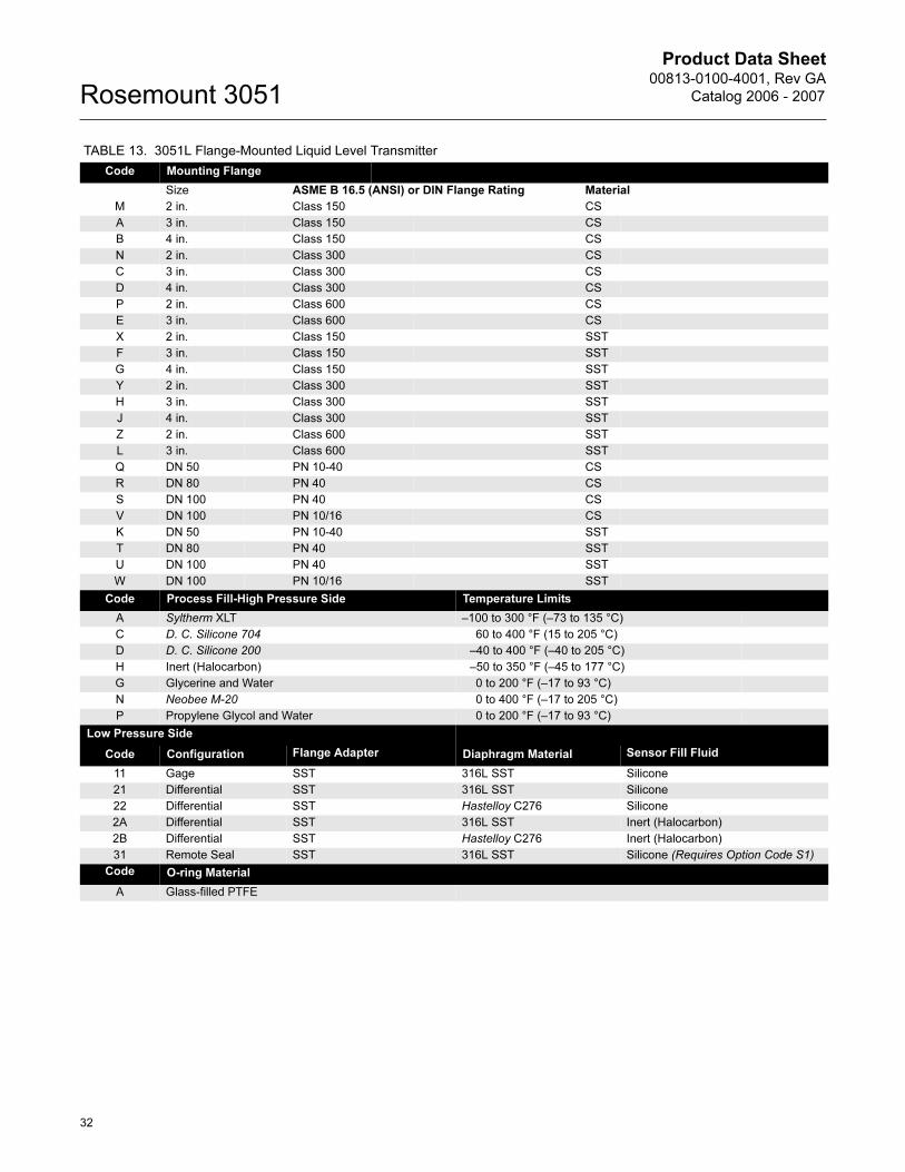
Product Data Sheet00813-0100-4001, Rev GA
Catalog 2006 - 2007Rosemount 3051
Code Mounting Flange
Size ASME B 16.5 (ANSI) or DIN Flange Rating Material
M 2 in. Class 150 CS
A 3 in. Class 150 CS
B 4 in. Class 150 CS
N 2 in. Class 300 CS
C 3 in. Class 300 CS
D 4 in. Class 300 CS
P 2 in. Class 600 CS
E 3 in. Class 600 CS
X 2 in. Class 150 SST
F 3 in. Class 150 SST
G 4 in. Class 150 SST
Y 2 in. Class 300 SST
H 3 in. Class 300 SST
J 4 in. Class 300 SST
Z 2 in. Class 600 SST
L 3 in. Class 600 SST
Q DN 50 PN 10-40 CS
R DN 80 PN 40 CS
S DN 100 PN 40 CS
V DN 100 PN 10/16 CS
K DN 50 PN 10-40 SST
T DN 80 PN 40 SST
U DN 100 PN 40 SST
W DN 100 PN 10/16 SST
Code Process Fill-High Pressure Side Temperature Limits
A Syltherm XLT –100 to 300 °F (–73 to 135 °C)
C D. C. Silicone 704 60 to 400 °F (15 to 205 °C)
D D. C. Silicone 200 –40 to 400 °F (–40 to 205 °C)
H Inert (Halocarbon) –50 to 350 °F (–45 to 177 °C)
G Glycerine and Water 0 to 200 °F (–17 to 93 °C)
N Neobee M-20 0 to 400 °F (–17 to 205 °C)
P Propylene Glycol and Water 0 to 200 °F (–17 to 93 °C)
Low Pressure Side
Code Configuration Flange Adapter Diaphragm Material Sensor Fill Fluid
11 Gage SST 316L SST Silicone
21 Differential SST 316L SST Silicone
22 Differential SST Hastelloy C276 Silicone
2A Differential SST 316L SST Inert (Halocarbon)
2B Differential SST Hastelloy C276 Inert (Halocarbon)
31 Remote Seal SST 316L SST Silicone (Requires Option Code S1)
Code O-ring Material
A Glass-filled PTFE
TABLE 13. 3051L Flange-Mounted Liquid Level Transmitter
32
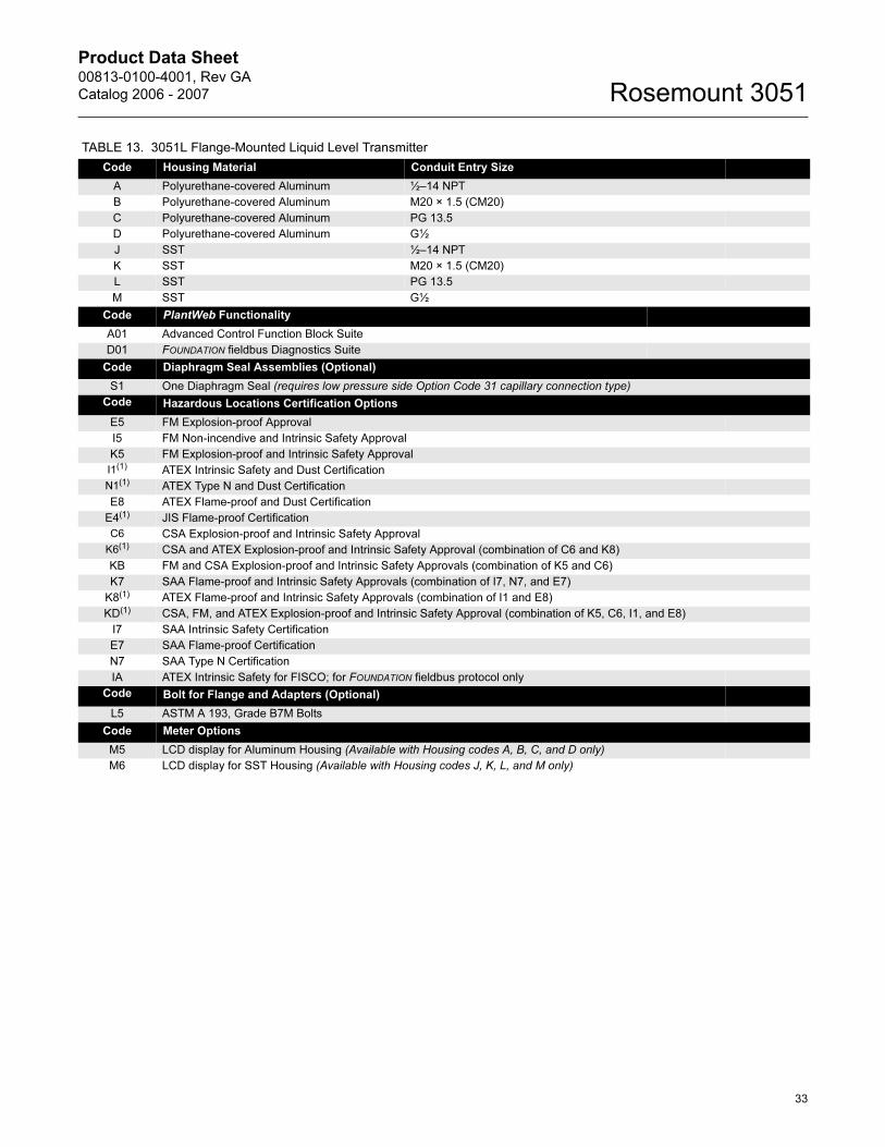
Product Data Sheet00813-0100-4001, Rev GA
Catalog 2006 - 2007 Rosemount 3051
Code Housing Material Conduit Entry Size
A Polyurethane-covered Aluminum ½–14 NPT
B Polyurethane-covered Aluminum M20 × 1.5 (CM20)
C Polyurethane-covered Aluminum PG 13.5
D Polyurethane-covered Aluminum G½
J SST ½–14 NPT
K SST M20 × 1.5 (CM20)
L SST PG 13.5
M SST G½
Code PlantWeb Functionality
A01 Advanced Control Function Block Suite
D01 FOUNDATION fieldbus Diagnostics Suite
Code Diaphragm Seal Assemblies (Optional)
S1 One Diaphragm Seal (requires low pressure side Option Code 31 capillary connection type)
Code Hazardous Locations Certification Options
E5 FM Explosion-proof Approval
I5 FM Non-incendive and Intrinsic Safety Approval
K5 FM Explosion-proof and Intrinsic Safety Approval
I1(1) ATEX Intrinsic Safety and Dust Certification
N1(1) ATEX Type N and Dust Certification
E8 ATEX Flame-proof and Dust Certification
E4(1) JIS Flame-proof Certification
C6 CSA Explosion-proof and Intrinsic Safety Approval
K6(1) CSA and ATEX Explosion-proof and Intrinsic Safety Approval (combination of C6 and K8)
KB FM and CSA Explosion-proof and Intrinsic Safety Approvals (combination of K5 and C6)
K7 SAA Flame-proof and Intrinsic Safety Approvals (combination of I7, N7, and E7)
K8(1) ATEX Flame-proof and Intrinsic Safety Approvals (combination of I1 and E8)
KD(1) CSA, FM, and ATEX Explosion-proof and Intrinsic Safety Approval (combination of K5, C6, I1, and E8)
I7 SAA Intrinsic Safety Certification
E7 SAA Flame-proof Certification
N7 SAA Type N Certification
IA ATEX Intrinsic Safety for FISCO; for FOUNDATION fieldbus protocol only
Code Bolt for Flange and Adapters (Optional)
L5 ASTM A 193, Grade B7M Bolts
Code Meter Options
M5 LCD display for Aluminum Housing (Available with Housing codes A, B, C, and D only)
M6 LCD display for SST Housing (Available with Housing codes J, K, L, and M only)
TABLE 13. 3051L Flange-Mounted Liquid Level Transmitter
33
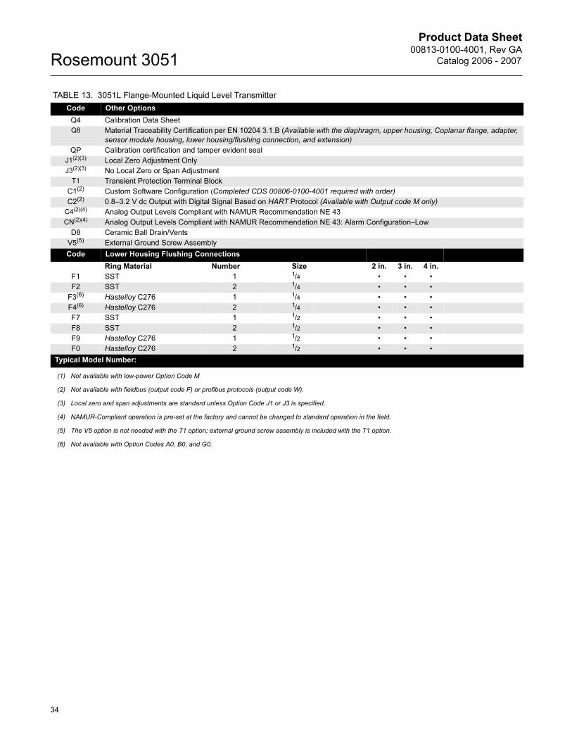
Product Data Sheet00813-0100-4001, Rev GA
Catalog 2006 - 2007Rosemount 3051
Code Other Options
Q4 Calibration Data Sheet
Q8 Material Traceability Certification per EN 10204 3.1.B (Available with the diaphragm, upper housing, Coplanar flange, adapter,
sensor module housing, lower housing/flushing connection, and extension)
QP Calibration certification and tamper evident seal
J1(2)(3) Local Zero Adjustment Only
J3(2)(3) No Local Zero or Span Adjustment
T1 Transient Protection Terminal Block
C1(2) Custom Software Configuration (Completed CDS 00806-0100-4001 required with order)
C2(2) 0.8–3.2 V dc Output with Digital Signal Based on HART Protocol (Available with Output code M only)
C4(2)(4) Analog Output Levels Compliant with NAMUR Recommendation NE 43
CN(2)(4) Analog Output Levels Compliant with NAMUR Recommendation NE 43: Alarm Configuration–Low
D8 Ceramic Ball Drain/Vents
V5(5) External Ground Screw Assembly
Code Lower Housing Flushing Connections Diaphragm /Size
Ring Material Number Size 2 in. 3 in. 4 in.
F1 SST 1 1/4 • • •
F2 SST 2 1/4 • • •
F3(6) Hastelloy C276 1 1/4 • • •
F4(6) Hastelloy C276 2 1/4 • • •
F7 SST 1 1/2 • • •
F8 SST 2 1/2 • • •
F9 Hastelloy C276 1 1/2 • • •
F0 Hastelloy C276 2 1/2 • • •
Typical Model Number:
(1) Not available with low-power Option Code M
(2) Not available with fieldbus (output code F) or profibus protocols (output code W).
(3) Local zero and span adjustments are standard unless Option Code J1 or J3 is specified.
(4) NAMUR-Compliant operation is pre-set at the factory and cannot be changed to standard operation in the field.
(5) The V5 option is not needed with the T1 option; external ground screw assembly is included with the T1 option.
(6) Not available with Option Codes A0, B0, and G0.
TABLE 13. 3051L Flange-Mounted Liquid Level Transmitter
34
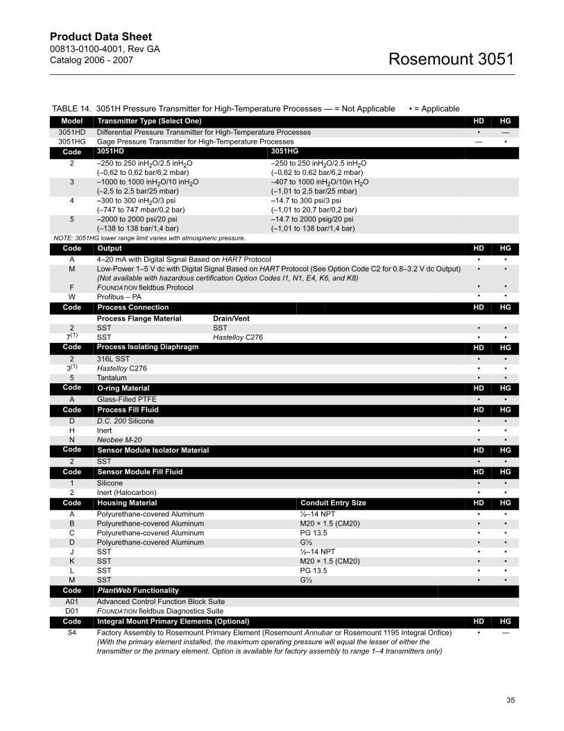
Product Data Sheet00813-0100-4001, Rev GA
Catalog 2006 - 2007 Rosemount 3051
TABLE 14. 3051H Pressure Transmitter for High-Temperature Processes — = Not Applicable • = Applicable
Model Transmitter Type (Select One) HD HG
3051HD Differential Pressure Transmitter for High-Temperature Processes • —
3051HG Gage Pressure Transmitter for High-Temperature Processes — •
Code 3051HD 3051HG
2 –250 to 250 inH2O/2.5 inH2O
(–0,62 to 0,62 bar/6,2 mbar)
–250 to 250 inH2O/2.5 inH2O
(–0,62 to 0,62 bar/6,2 mbar)
3 –1000 to 1000 inH2O/10 inH2O
(–2,5 to 2,5 bar/25 mbar)
–407 to 1000 inH2O/10in H2O
(–1,01 to 2,5 bar/25 mbar)
4 –300 to 300 inH2O/3 psi
(–747 to 747 mbar/0,2 bar)
–14.7 to 300 psi/3 psi
(–1,01 to 20,7 bar/0,2 bar)
5 –2000 to 2000 psi/20 psi
(–138 to 138 bar/1,4 bar)
–14.7 to 2000 psig/20 psi
(–1,01 to 138 bar/1,4 bar)
NOTE: 3051HG lower range limit varies with atmospheric pressure.
Code Output HD HG
A 4–20 mA with Digital Signal Based on HART Protocol • •
M Low-Power 1–5 V dc with Digital Signal Based on HART Protocol (See Option Code C2 for 0.8–3.2 V dc Output)
(Not available with hazardous certification Option Codes I1, N1, E4, K6, and K8)
• •
F FOUNDATION fieldbus Protocol • •
W Profibus – PA • •
Code Process Connection HD HG
Process Flange Material Drain/Vent
2 SST SST • •
7(1) SST Hastelloy C276 • •
Code Process Isolating Diaphragm HD HG
2 316L SST • •
3(1) Hastelloy C276 • •
5 Tantalum • •
Code O-ring Material HD HG
A Glass-Filled PTFE • •
Code Process Fill Fluid HD HG
D D.C. 200 Silicone • •
H Inert • •
N Neobee M-20 • •
Code Sensor Module Isolator Material HD HG
2 SST • •
Code Sensor Module Fill Fluid HD HG
1 Silicone • •
2 Inert (Halocarbon) • •
Code Housing Material Conduit Entry Size HD HG
A Polyurethane-covered Aluminum ½–14 NPT • •
B Polyurethane-covered Aluminum M20 × 1.5 (CM20) • •
C Polyurethane-covered Aluminum PG 13.5 • •
D Polyurethane-covered Aluminum G½ • •
J SST ½–14 NPT • •
K SST M20 × 1.5 (CM20) • •
L SST PG 13.5 • •
M SST G½ • •
Code PlantWeb Functionality
A01 Advanced Control Function Block Suite
D01 FOUNDATION fieldbus Diagnostics Suite
Code Integral Mount Primary Elements (Optional) HD HG
S4 Factory Assembly to Rosemount Primary Element (Rosemount Annubar or Rosemount 1195 Integral Orifice)
(With the primary element installed, the maximum operating pressure will equal the lesser of either the
transmitter or the primary element. Option is available for factory assembly to range 1–4 transmitters only)
• —
35
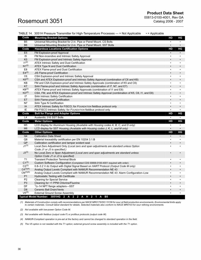
Product Data Sheet00813-0100-4001, Rev GA
Catalog 2006 - 2007Rosemount 3051
Code Mounting Bracket Options HD HG
B5 Universal Mounting Bracket for 2-in. Pipe or Panel Mount, CS Bolts • •
B6 Universal Mounting Bracket for 2-in. Pipe or Panel Mount, SST Bolts • •
Code Hazardous Locations Certification Options HD HG
E5 FM Explosion-proof Approval • •
I5 FM Non-incendive and Intrinsic Safety Approval • •
K5 FM Explosion-proof and Intrinsic Safety Approval • •
I1(2) ATEX Intrinsic Safety and Dust Certification • •
N1(2) ATEX Type N and Dust Certification • •
E8 ATEX Flame-proof and Dust Certification • •
E4(2) JIS Flame-proof Certification • •
C6 CSA Explosion-proof and Intrinsic Safety Approval • •
K6(2) CSA and ATEX Explosion-proof and Intrinsic Safety Approval (combination of C6 and K8) • •
KB FM and CSA Explosion-proof and Intrinsic Safety Approvals (combination of K5 and C6) • •
K7 SAA Flame-proof and Intrinsic Safety Approvals (combination of I7, N7, and E7) • •
KB(2) ATEX Flame-proof and Intrinsic Safety Approvals (combination of I1 and E8) • •
KD(2) CSA, FM, and ATEX Explosion-proof and Intrinsic Safety Approval (combination of K5, C6, I1, and E8) • •
I7 SAA Intrinsic Safety Certification • •
E7 SAA Flame-proof Certification • •
N7 SAA Type N Certification • •
IA ATEX Intrinsic Safety for FISCO; for FOUNDATION fieldbus protocol only • •
IE FM FISCO Intrinsic Safety; for FOUNDATION fieldbus protocol only • •
Code Bolt for Flange and Adapter Options HD HG
L4 Austenitic 316 SST Bolts • •
Code Meter Options HD HG
M5 LCD display for Aluminum Housing (Available with Housing codes A, B, C, and D only) • •
M6 LCD display for SST Housing (Available with Housing codes J, K, L, and M only) • •
Code Other Options HD HG
Q4 Calibration Data Sheet • •
Q8 Material traceability certification per EN 10204 3.1.B • •
QP Calibration certification and tamper evident seal • •
J1(3) Local Zero Adjustment Only (Local zero and span adjustments are standard unless Option
Code J1 or J3 is specified.)
• •
J3(3) No Local Zero or Span Adjustment (Local zero and span adjustments are standard unless
Option Code J1 or J3 is specified)
• •
T1 Transient Protection Terminal Block • •
C1(3) Custom Software Configuration (Completed CDS 00806-0100-4001 required with order) • •
C2(3) 0.8–3.2 V dc Output with Digital Signal Based on HART Protocol (Output Code M only) • •
C4(3)(4) Analog Output Levels Compliant with NAMUR Recommendation NE 43 • •
CN(3)(4) Analog Output Levels Compliant with NAMUR Recommendation NE 43: Alarm Configuration–Low • •
P1 Hydrostatic Testing with Certificate • •
P2 Cleaning for Special Service • •
P3 Cleaning for <1 PPM Chlorine/Fluorine • •
DF 1/2–14 NPT flange adapters—SST • •
D8 Ceramic Ball Drain/Vents • •
V5(5) External Ground Screw Assembly • •
Typical Model Number: 3051HG 2 A 2 2 A H 2 1 A B5
(1) Materials of Construction comply with recommendations per NACE MR0175/ISO 15156 for sour oil field production environments. Environmental limits apply to certain materials. Consult latest standard for details. Selected materials also conform to NACE MR0103 for sour refining environments.
(2) Not available with low-power Option Code M.
(3) Not available with fieldbus (output code F) or profibus protocols (output code W).
(4) NAMUR-Compliant operation is pre-set at the factory and cannot be changed to standard operation in the field.
(5) The V5 option is not needed with the T1 option; external ground screw assembly is included with the T1 option.
TABLE 14. 3051H Pressure Transmitter for High-Temperature Processes — = Not Applicable • = Applicable
36
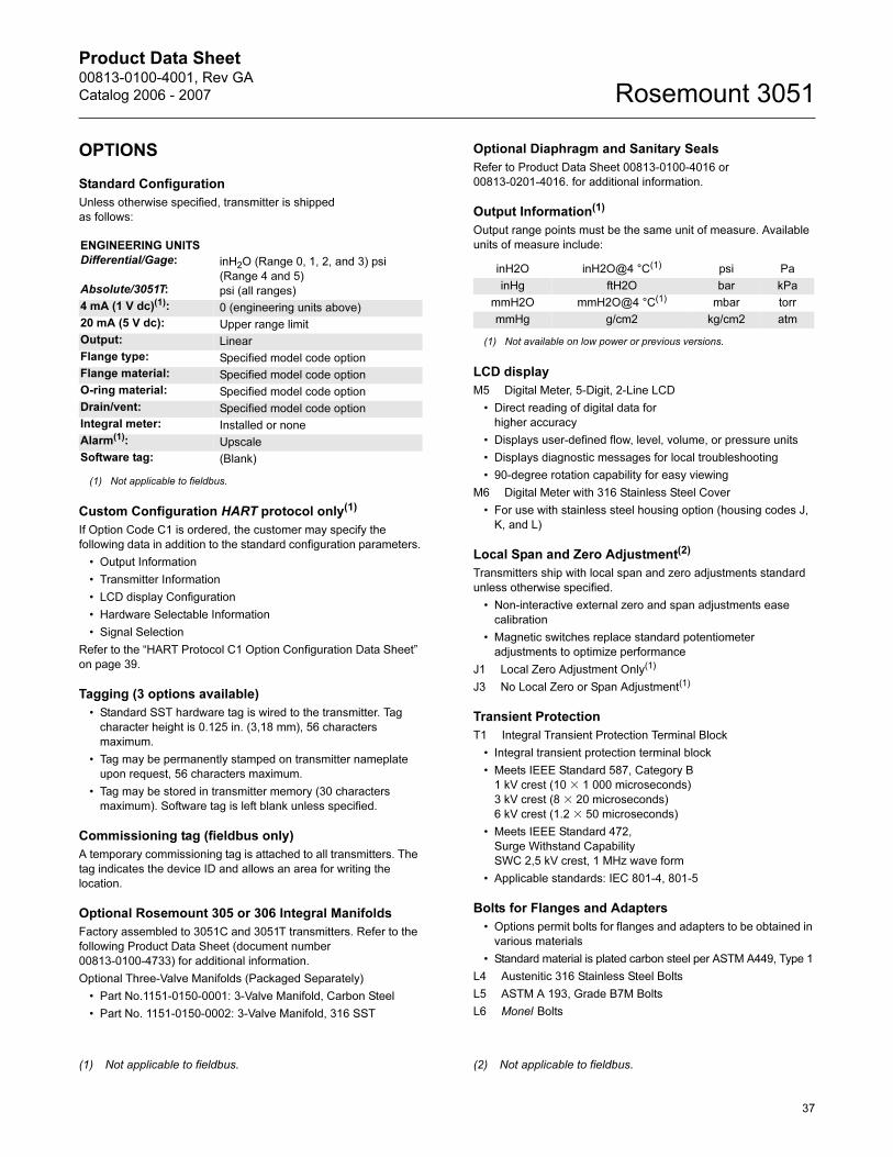
Product Data Sheet00813-0100-4001, Rev GA
Catalog 2006 - 2007 Rosemount 3051
OPTIONS
Standard Configuration
Unless otherwise specified, transmitter is shipped
as follows:
Custom Configuration HART protocol only(1)
If Option Code C1 is ordered, the customer may specify the
following data in addition to the standard configuration parameters.
• Output Information
• Transmitter Information
• LCD display Configuration
• Hardware Selectable Information
• Signal Selection
Refer to the “HART Protocol C1 Option Configuration Data Sheet”
on page 39.
Tagging (3 options available)
• Standard SST hardware tag is wired to the transmitter. Tag
character height is 0.125 in. (3,18 mm), 56 characters
maximum.
• Tag may be permanently stamped on transmitter nameplate
upon request, 56 characters maximum.
• Tag may be stored in transmitter memory (30 characters
maximum). Software tag is left blank unless specified.
Commissioning tag (fieldbus only)
A temporary commissioning tag is attached to all transmitters. The
tag indicates the device ID and allows an area for writing the
location.
Optional Rosemount 305 or 306 Integral Manifolds
Factory assembled to 3051C and 3051T transmitters. Refer to the
following Product Data Sheet (document number
00813-0100-4733) for additional information.
Optional Three-Valve Manifolds (Packaged Separately)
• Part No.1151-0150-0001: 3-Valve Manifold, Carbon Steel
• Part No. 1151-0150-0002: 3-Valve Manifold, 316 SST
Optional Diaphragm and Sanitary Seals
Refer to Product Data Sheet 00813-0100-4016 or
00813-0201-4016. for additional information.
Output Information(1)
Output range points must be the same unit of measure. Available
units of measure include:
LCD display
M5 Digital Meter, 5-Digit, 2-Line LCD
• Direct reading of digital data for
higher accuracy
• Displays user-defined flow, level, volume, or pressure units
• Displays diagnostic messages for local troubleshooting
• 90-degree rotation capability for easy viewing
M6 Digital Meter with 316 Stainless Steel Cover
• For use with stainless steel housing option (housing codes J,
K, and L)
Local Span and Zero Adjustment(2)
Transmitters ship with local span and zero adjustments standard
unless otherwise specified.
• Non-interactive external zero and span adjustments ease
calibration
• Magnetic switches replace standard potentiometer
adjustments to optimize performance
J1 Local Zero Adjustment Only(1)
J3 No Local Zero or Span Adjustment(1)
Transient Protection
T1 Integral Transient Protection Terminal Block
• Integral transient protection terminal block
• Meets IEEE Standard 587, Category B
1 kV crest (10 � 1 000 microseconds)
3 kV crest (8 � 20 microseconds)
6 kV crest (1.2 � 50 microseconds)
• Meets IEEE Standard 472,
Surge Withstand Capability
SWC 2,5 kV crest, 1 MHz wave form
• Applicable standards: IEC 801-4, 801-5
Bolts for Flanges and Adapters
• Options permit bolts for flanges and adapters to be obtained in
various materials
• Standard material is plated carbon steel per ASTM A449, Type 1
L4 Austenitic 316 Stainless Steel Bolts
L5 ASTM A 193, Grade B7M Bolts
L6 Monel Bolts
ENGINEERING UNITS
Differential/Gage:
Absolute/3051T:
inH2O (Range 0, 1, 2, and 3) psi
(Range 4 and 5)
psi (all ranges)
4 mA (1 V dc)(1):
(1) Not applicable to fieldbus.
0 (engineering units above)
20 mA (5 V dc): Upper range limit
Output: Linear
Flange type: Specified model code option
Flange material: Specified model code option
O-ring material: Specified model code option
Drain/vent: Specified model code option
Integral meter: Installed or none
Alarm(1): Upscale
Software tag: (Blank)
(1) Not applicable to fieldbus.
inH2O inH2O@4 °C(1)
(1) Not available on low power or previous versions.
psi Pa
inHg ftH2O bar kPa
mmH2O mmH2O@4 °C(1) mbar torr
mmHg g/cm2 kg/cm2 atm
(2) Not applicable to fieldbus.
37
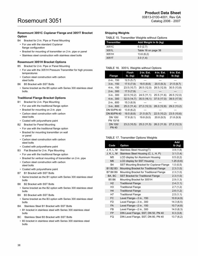
Product Data Sheet00813-0100-4001, Rev GA
Catalog 2006 - 2007Rosemount 3051
Rosemount 3051C Coplanar Flange and 3051T Bracket
Option
B4 Bracket for 2-in. Pipe or Panel Mounting
• For use with the standard Coplanar
flange configuration
• Bracket for mounting of transmitter on 2-in. pipe or panel
• Stainless steel construction with stainless steel bolts
Rosemount 3051H Bracket Options
B5 Bracket for 2-in. Pipe or Panel Mounting
• For use with the 3051H Pressure Transmitter for high process
temperatures
• Carbon steel construction with carbon
steel bolts
B6 B5 Bracket with SST Bolts
• Same bracket as the B5 option with Series 300 stainless steel
bolts.
Traditional Flange Bracket Options
B1 Bracket for 2-in. Pipe Mounting
• For use with the traditional flange option
• Bracket for mounting on 2-in. pipe
• Carbon steel construction with carbon
steel bolts
• Coated with polyurethane paint
B2 Bracket for Panel Mounting
• For use with the traditional flange option
• Bracket for mounting transmitter on wall
or panel
• Carbon steel construction with carbon
steel bolts
• Coated with polyurethane paint
B3 Flat Bracket for 2-in. Pipe Mounting
• For use with the traditional flange option
• Bracket for vertical mounting of transmitter on 2-in. pipe
• Carbon steel construction with carbon
steel bolts
• Coated with polyurethane paint
B7 B1 Bracket with SST Bolts
• Same bracket as the B1 option with Series 300 stainless steel
bolts
B8 B2 Bracket with SST Bolts
• Same bracket as the B2 option with Series 300 stainless steel
bolts
B9 B3 Bracket with SST Bolts
• Same bracket as the B3 option with Series 300 stainless steel
bolts
BA Stainless Steel B1 Bracket with SST Bolts
• B1 bracket in stainless steel with Series 300 stainless steel
bolts
BC Stainless Steel B3 Bracket with SST Bolts
• B3 bracket in stainless steel with Series 300 stainless steel
bolts
Shipping Weights
TABLE 15. Transmitter Weights without Options
Transmitter Add Weight In lb (kg)
3051C 6.0 (2,7)
3051L Table 16 on page 38
3051H 13.6 (6,2)
3051T 3.0 (1,4)
TABLE 16. 3051L Weights without Options
Flange
Flush
lb. (kg)
2-in. Ext.
lb (kg)
4-in. Ext.
lb (kg)
6-in. Ext.
lb (kg)
2-in., 150 12.5 (5,7) — — —
3-in., 150 17.5 (7,9) 19.5 (8,8) 20.5 (9,3) 21.5 (9,7)
4-in., 150 23.5 (10,7) 26.5 (12,0) 28.5 (12,9) 30.5 (13,8)
2-in., 300 17.5 (7,9) — — —
3-in., 300 22.5 (10,2) 24.5 (11,1) 25.5 (11,6) 26.5 (12,0)
4-in., 300 32.5 (14,7) 35.5 (16,1) 37.5 (17,0) 39.5 (17,9)
2-in., 600 15.3 (6,9) — — —
3-in., 600 25.2 (11,4) 27.2 (12,3) 28.2 (12,8) 29.2 (13,2)
DN 50/PN 40 13.8 (6,2) — — —
DN 80/PN 40 19.5 (8,8) 21.5 (9,7) 22.5 (10,2) 23.5 (10,6)
DN 100/
PN 10/16
17.8 (8,1) 19.8 (9,0) 20.8 (9,5) 21.8 (9,9)
DN 100/
PN 40
23.2 (10,5) 25.2 (11,5) 26.2 (11,9) 27.2 (12,3)
TABLE 17. Transmitter Options Weights
Code Option
Add
lb (kg)
J, K, L, M Stainless Steel Housing(T) 3.9 (1,8)
J, K, L, M Stainless Steel Housing (C, L, H, P) 3.1 (1,4)
M5 LCD display for Aluminum Housing 0.5 (0,2)
M6 LCD display for SST Housing 1.25 (0,6)
B4 SST Mounting Bracket for Coplanar Flange 1.0 (0,5)
B1 B2 B3 Mounting Bracket for Traditional Flange 2.3 (1,0)
B7 B8 B9 Mounting Bracket for Traditional Flange 2.3 (1,0)
BA, BC SST Bracket for Traditional Flange 2.3 (1,0)
B5 B6 Mounting Bracket for 3051H 2.9 (1,3)
H2 Traditional Flange 2.4 (1,1)
H3 Traditional Flange 2.7 (1,2)
H4 Traditional Flange 2.6 (1,2)
H7 Traditional Flange 2.5 (1,1)
FC Level Flange—3 in., 150 10.8 (4,9)
FD Level Flange—3 in., 300 14.3 (6,5)
FA Level Flange—2 in., 150 10.7 (4,8)
FB Level Flange—2 in., 300 14.0 (6,3)
FP DIN Level Flange, SST, DN 50, PN 40 8.3 (3,8)
FQ DIN Level Flange, SST, DN 80, PN 40 13.7 (6,2)
38
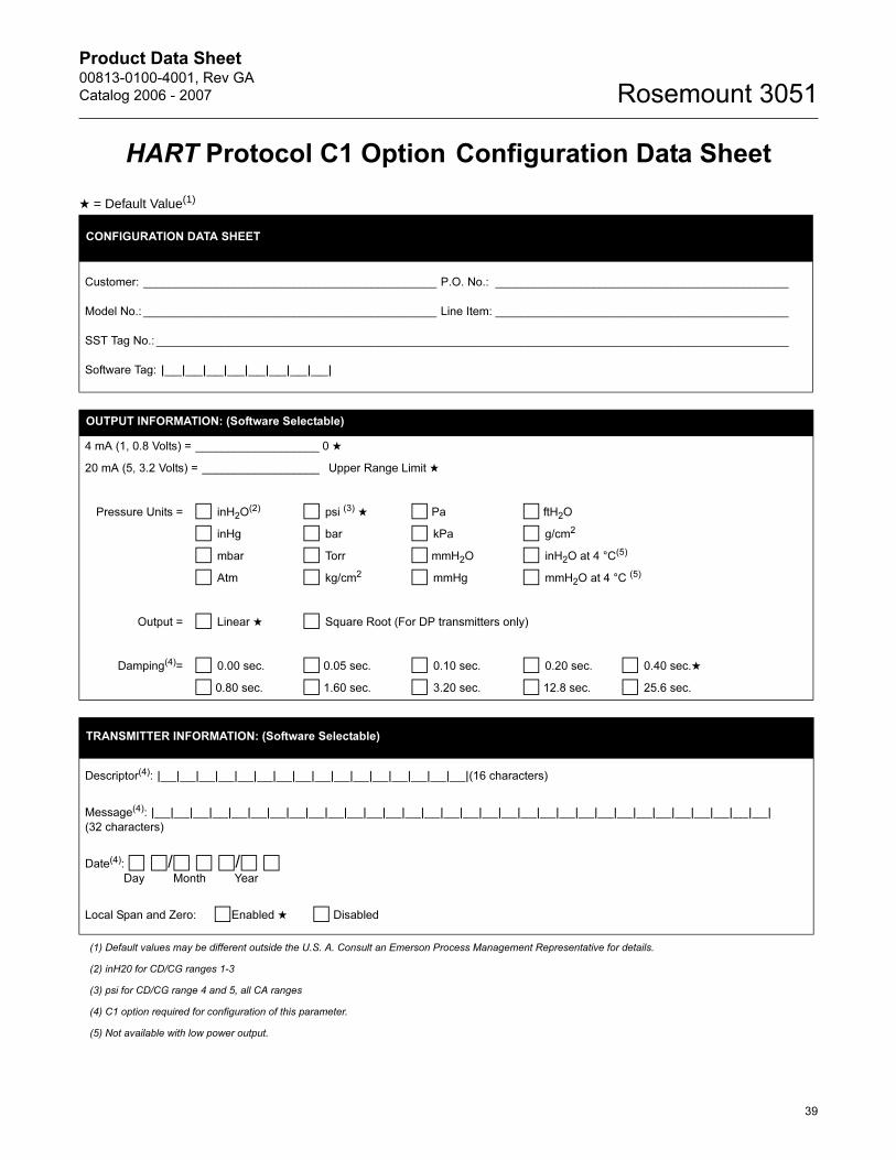
Product Data Sheet00813-0100-4001, Rev GA
Catalog 2006 - 2007 Rosemount 3051
HART Protocol C1 Option Configuration Data Sheet
★ = Default Value(1)
(1) Default values may be different outside the U.S. A. Consult an Emerson Process Management Representative for details.
(2) inH20 for CD/CG ranges 1-3
(3) psi for CD/CG range 4 and 5, all CA ranges
(4) C1 option required for configuration of this parameter.
(5) Not available with low power output.
CONFIGURATION DATA SHEET
Customer: _____________________________________________ P.O. No.: _____________________________________________
Model No.: _____________________________________________ Line Item: _____________________________________________
SST Tag No.: _________________________________________________________________________________________________
Software Tag: |__|__|__|__|__|__|__|__|
OUTPUT INFORMATION: (Software Selectable)
4 mA (1, 0.8 Volts) = ___________________ 0 ★
20 mA (5, 3.2 Volts) = __________________ Upper Range Limit ★
Pressure Units = □ inH2O(2) □ psi (3) ★ □ Pa □ ftH2O
□ inHg □ bar □ kPa □ g/cm2
□ mbar □ Torr □ mmH2O □ inH2O at 4 °C(5)
□ Atm □ kg/cm2 □ mmHg □ mmH2O at 4 °C (5)
Output = □ Linear ★ □ Square Root (For DP transmitters only)
Damping(4)= □ 0.00 sec. □ 0.05 sec. □ 0.10 sec. □ 0.20 sec. □ 0.40 sec.★
□ 0.80 sec. □ 1.60 sec. □ 3.20 sec. □ 12.8 sec. □ 25.6 sec.
TRANSMITTER INFORMATION: (Software Selectable)
Descriptor(4): |__|__|__|__|__|__|__|__|__|__|__|__|__|__|__|__|(16 characters)
Message(4): |__|__|__|__|__|__|__|__|__|__|__|__|__|__|__|__|__|__|__|__|__|__|__|__|__|__|__|__|__|__|__|__|
(32 characters)
Date(4): □ □/□ □ □/□ □Day Month Year
Local Span and Zero: □Enabled ★ □ Disabled
39
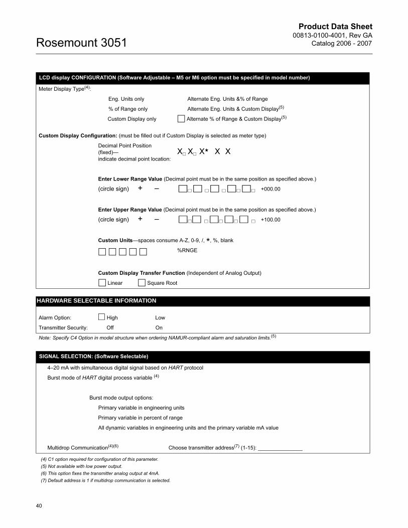
Product Data Sheet00813-0100-4001, Rev GA
Catalog 2006 - 2007Rosemount 3051
(4) C1 option required for configuration of this parameter.
(5) Not available with low power output.
(6) This option fixes the transmitter analog output at 4mA.
(7) Default address is 1 if multidrop communication is selected.
LCD display CONFIGURATION (Software Adjustable – M5 or M6 option must be specified in model number)
Meter Display Type(4):
Eng. Units only Alternate Eng. Units &% of Range
% of Range only Alternate Eng. Units & Custom Display(5)
Custom Display only □ Alternate % of Range & Custom Display(5)
Custom Display Configuration: (must be filled out if Custom Display is selected as meter type)
Decimal Point Position
(fixed)—
indicate decimal point location:
X� X� X★ X X
Enter Lower Range Value (Decimal point must be in the same position as specified above.)
(circle sign) + –
□� □ � □ � □� □� +000.00
Enter Upper Range Value (Decimal point must be in the same position as specified above.)
(circle sign) + –
□�□ � □� □� □ � +100.00
Custom Units—spaces consume A-Z, 0-9, /, *
, %, blank
□ □ □ □ □ %RNGE
Custom Display Transfer Function (Independent of Analog Output)
□ Linear □ Square Root
HARDWARE SELECTABLE INFORMATION
Alarm Option: � High Low
Transmitter Security: Off On
Note: Specify C4 Option in model structure when ordering NAMUR-compliant alarm and saturation limits.(5)
SIGNAL SELECTION: (Software Selectable)
4–20 mA with simultaneous digital signal based on HART protocol
Burst mode of HART digital process variable (4)
Burst mode output options:
Primary variable in engineering units
Primary variable in percent of range
All dynamic variables in engineering units and the primary variable mA value
Multidrop Communication(4)(6) Choose transmitter address(7) (1-15): _______________
40
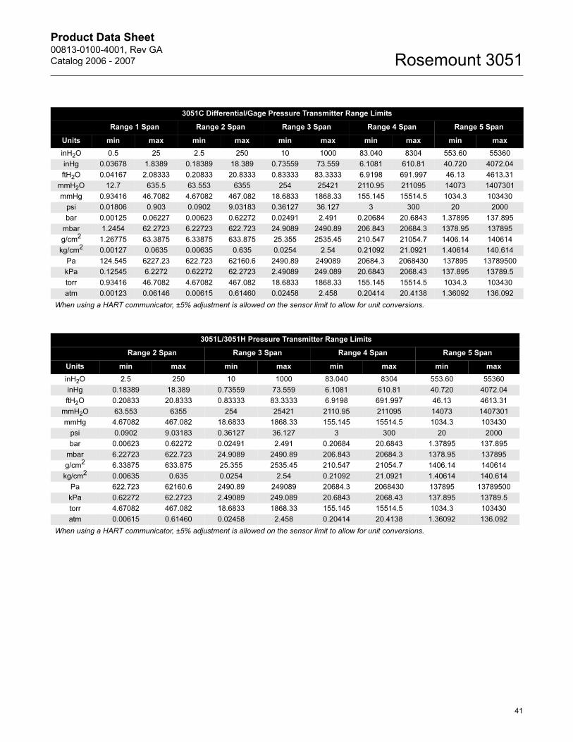
Product Data Sheet00813-0100-4001, Rev GA
Catalog 2006 - 2007 Rosemount 3051
3051C Differential/Gage Pressure Transmitter Range Limits
Range 1 Span Range 2 Span Range 3 Span Range 4 Span Range 5 Span
Units min max min max min max min max min max
inH2O 0.5 25 2.5 250 10 1000 83.040 8304 553.60 55360
inHg 0.03678 1.8389 0.18389 18.389 0.73559 73.559 6.1081 610.81 40.720 4072.04
ftH2O 0.04167 2.08333 0.20833 20.8333 0.83333 83.3333 6.9198 691.997 46.13 4613.31
mmH2O 12.7 635.5 63.553 6355 254 25421 2110.95 211095 14073 1407301
mmHg 0.93416 46.7082 4.67082 467.082 18.6833 1868.33 155.145 15514.5 1034.3 103430
psi 0.01806 0.903 0.0902 9.03183 0.36127 36.127 3 300 20 2000
bar 0.00125 0.06227 0.00623 0.62272 0.02491 2.491 0.20684 20.6843 1.37895 137.895
mbar 1.2454 62.2723 6.22723 622.723 24.9089 2490.89 206.843 20684.3 1378.95 137895
g/cm2 1.26775 63.3875 6.33875 633.875 25.355 2535.45 210.547 21054.7 1406.14 140614
kg/cm2 0.00127 0.0635 0.00635 0.635 0.0254 2.54 0.21092 21.0921 1.40614 140.614
Pa 124.545 6227.23 622.723 62160.6 2490.89 249089 20684.3 2068430 137895 13789500
kPa 0.12545 6.2272 0.62272 62.2723 2.49089 249.089 20.6843 2068.43 137.895 13789.5
torr 0.93416 46.7082 4.67082 467.082 18.6833 1868.33 155.145 15514.5 1034.3 103430
atm 0.00123 0.06146 0.00615 0.61460 0.02458 2.458 0.20414 20.4138 1.36092 136.092
When using a HART communicator, ±5% adjustment is allowed on the sensor limit to allow for unit conversions.
3051L/3051H Pressure Transmitter Range Limits
Range 2 Span Range 3 Span Range 4 Span Range 5 Span
Units min max min max min max min max
inH2O 2.5 250 10 1000 83.040 8304 553.60 55360
inHg 0.18389 18.389 0.73559 73.559 6.1081 610.81 40.720 4072.04
ftH2O 0.20833 20.8333 0.83333 83.3333 6.9198 691.997 46.13 4613.31
mmH2O 63.553 6355 254 25421 2110.95 211095 14073 1407301
mmHg 4.67082 467.082 18.6833 1868.33 155.145 15514.5 1034.3 103430
psi 0.0902 9.03183 0.36127 36.127 3 300 20 2000
bar 0.00623 0.62272 0.02491 2.491 0.20684 20.6843 1.37895 137.895
mbar 6.22723 622.723 24.9089 2490.89 206.843 20684.3 1378.95 137895
g/cm2 6.33875 633.875 25.355 2535.45 210.547 21054.7 1406.14 140614
kg/cm2 0.00635 0.635 0.0254 2.54 0.21092 21.0921 1.40614 140.614
Pa 622.723 62160.6 2490.89 249089 20684.3 2068430 137895 13789500
kPa 0.62272 62.2723 2.49089 249.089 20.6843 2068.43 137.895 13789.5
torr 4.67082 467.082 18.6833 1868.33 155.145 15514.5 1034.3 103430
atm 0.00615 0.61460 0.02458 2.458 0.20414 20.4138 1.36092 136.092
When using a HART communicator, ±5% adjustment is allowed on the sensor limit to allow for unit conversions.
41
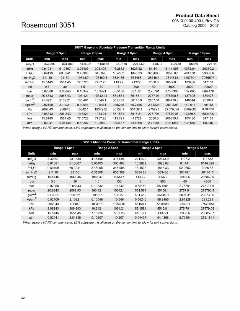
Product Data Sheet00813-0100-4001, Rev GA
Catalog 2006 - 2007Rosemount 3051
3051T Gage and Absolute Pressure Transmitter Range Limits
Range 1 Span Range 2 Span Range 3 Span Range 4 Span Range 5 Span
Units min max min max min max min max min max
inH2O 8.30397 831.889 41.5198 4159.45 221.439 22143.9 1107.2 110720 55360 276799
inHg 0.61081 61.0807 3.05403 305.403 16.2882 1628.82 81.441 8144.098 4072.04 20360.2
ftH2O 0.69199 69.3241 3.45998 345.998 18.4533 1845.33 92.2663 9226.63 4613.31 23066.6
mmH2O 211.10 21130 1054.60 105460.3 5634.66 563466 28146.1 2814613 1407301 7036507
mmHg 15.5145 1551.45 77.5723 7757.23 413.72 41372 2068.6 206860.0 103430 517151
psi 0.3 30 1.5 150 8 800 40 4000 2000 10000
bar 0.02068 3.06843 0.10342 10.3421 0.55158 55.1581 2.75791 275.7905 137.895 689.476
mbar 20.6843 2068.43 103.421 10342.11 551.581 55158.1 2757.91 275790.5 137895 689476
g/cm2 21.0921 2109.21 105.461 10546.1 561.459 56145.9 2807.31 280730.6 140614 703067
kg/cm2 0.02109 2.10921 0.10546 10.5461 0.56246 56.2456 2.81228 281.228 140.614 701.82
Pa 2068.43 206843 10342.1 1034212 55158.1 5515811 275791 27579054 13789500 68947600
kPa 2.06843 206.843 10.3421 1034.21 55.1581 5515.81 275.791 27579.05 13789.5 68947.6
torr 15.5145 1551.45 77.5726 7757.26 413.721 413721 2068.6 206859.7 103430 517151
atm 0.02041 2.04138 0.10207 10.2069 0.54437 54.4368 2.72184 272.1841 136.092 680.46
When using a HART communicator, ±5% adjustment is allowed on the sensor limit to allow for unit conversions.
3051C Absolute Pressure Transmitter Range Limits
Range 1 Span Range 2 Span Range 3 Span Range 4 Span
Units min max min max min max min max
inH2O 8.30397 831.889 41.5198 4151.98 221.439 22143.9 1107.2 110720
inHg 0.61081 61.0807 3.05403 305.403 16.2882 1628.82 81.441 8144.098
ftH2O 0.69199 69.3241 3.45998 345.998 18.4533 1845.33 92.2663 9226.63
mmH2O 211.10 21130 6.35308 635.308 5634.66 563466 28146.1 2814613
mmHg 15.5145 1551.45 1055.47 105547 413.72 41372 2068.6 206860.0
psi 0.3 30 1.5 150 8 800 40 4000
bar 0.02068 2.06843 0.10342 10.342 0.55158 55.1581 2.75791 275.7905
mbar 20.6843 2068.43 103.421 10342.1 551.581 55158.1 2757.91 275790.5
g/cm2 21.0921 2109.21 105.27 105.27 561.459 56145.9 2807.31 280730.6
kg/cm2 0.02109 2.10921 0.10546 10.546 0.56246 56.2456 2.81228 281.228
Pa 2068.43 206843 10342.1 1034210 55158.1 5515811 275791 27579054
kPa 2.06843 206.843 10.3421 1034.21 55.1581 5515.81 275.791 27579.05
torr 15.5145 1551.45 77.5726 7757.26 413.721 413721 2068.6 206859.7
atm 0.02041 2.04138 0.10207 10.207 0.54437 54.4368 2.72184 272.1841
When using a HART communicator, ±5% adjustment is allowed on the sensor limit to allow for unit conversions.
42

Product Data Sheet00813-0100-4001, Rev GA
Catalog 2006 - 2007 Rosemount 3051
43
Product Data Sheet00813-0100-4001, Rev GA
Catalog 2006 - 2007Rosemount 3051
Rosemount, Annubar, ProPlate, and the Rosemount logotype are registered trademarks of Rosemount Inc.PlantWeb is a registered trademark of one of the Emerson Process Management group of companies.Complete Point Solutions, Coplanar and Multivariable are trademarks of Rosemount Inc.HART is a registered trademark of the HART Communications Foundation.Hastelloy is a registered trademarks of Haynes international, Inc..Monel is a registered trademark of the Special Metals Corporation group of Companies.Syltherm 800, Dow Corning, and D.C. are registered trademarks of Dow Corning Co.Teflon is a registered trademark of E.I. du Pont de Nemours & Co.Neobee M-20 is a registered trademark of Stephan Chemical Co.The 3-A symbol is a registered trademark of the 3-A Sanitary Standards Symbol Council.FOUNDATION fieldbus is a registered trademark of the Fieldbus Foundation.
Emerson Process Management
© 2006 Rosemount Inc. All rights reserved.
¢00813-0100-4001;¤
Fluorinert is a registered trademark of 3M Company.
All other marks are the property of their respective owners.
Rosemount Model 3051 Smart Pressure Transmitters may be protected by one or more of the following U.S. Patent Nos. 4,370,890; 4,466,290; 4,612,812; 4,791,352; 4,798,089; 4,818,994; 4,833,922; 4,866,435; 4,926,340; 4,988,990; and 5,028,746. Mexico Patentado No. 154,961. May depend on model. Other foreign patents issued and pending.
Rosemount Inc.8200 Market BoulevardChanhassen, MN 55317 USAT (U.S.) 1 800 999 9307T (International) (952) 906 8888F (952) 949 7001
www.rosemount.com
Emerson Process Management Heath PlaceBognor RegisWest Sussex PO22 9SHEnglandT 44 (0) 1243 863121F 44 (0) 1243 867554
Emerson Process Management Asia Pacific Private Limited1 Pandan CrescentSingapore 128461T (65) 6777 8211F (65) 6777 [email protected]