Embed Size (px)
Citation preview
www.rosemount.com
Reference Manual 00809-0100-4130, Rev AAMay 2009
Rosemount 2130Extreme Temperature Vibrating Fork Liquid Level Switch

www.rosemount.com
Reference Manual00809-0100-4130, Rev AAMay 2009 Rosemount 2130
IMPORTANT NOTICE
Read this manual before working with the product. For personal and system safety, and for optimum product performance, make sure you thoroughly understand the contents before installing, using, or maintaining this product.Within the United States, Rosemount Inc. has two toll-free assistance numbers.Customer Central: 1-800-999-9307 (7:00 a.m. to 7:00 p.m. CST)Technical support, quoting, and order-related questions.North American Response Center:
Equipment service needs.1-800-654-7768 (24 hours a day – Includes Canada)For equipment service or support needs outside the United States, contact your local Emerson representative.
CAUTION
The products described in this document are NOT designed for nuclear-qualified applications. Using non-nuclear qualified products in applications that require nuclear-qualified hardware or products may cause inaccurate readings.For information on Rosemount nuclear-qualified products, contact your local Emerson Sales Representative.
CAUTION
Emerson pursues a policy of continuous development and product improvement. The specification in this document may therefore be changed without notice. To the best of our knowledge, the information contained in this document is accurate and Rosemount cannot be held responsible for any errors, omissions or other misinformation contained herein. No part of this document may be photocopied or reproduced without the prior written consent of Emerson.
Rosemount 2130
Extreme TemperatureVibrating Fork LiquidLevel Switch

Reference Manual00809-0100-4130, Rev AA
May 2009Rosemount 2130
www.rosemount.com
Reference Manual00809-0100-4130, Rev AAMay 2009 Rosemount 2130
Table of Contents
SECTION 1Introduction
Safety Messages . . . . . . . . . . . . . . . . . . . . . . . . . . . . . . . . . . . . . . . . . 1-1Switch Overview . . . . . . . . . . . . . . . . . . . . . . . . . . . . . . . . . . . . . . . . . 1-2
Measurement Principle. . . . . . . . . . . . . . . . . . . . . . . . . . . . . . . . . . 1-3Short Fork Technology . . . . . . . . . . . . . . . . . . . . . . . . . . . . . . . . . . 1-3Special Features. . . . . . . . . . . . . . . . . . . . . . . . . . . . . . . . . . . . . . . 1-3
Rosemount 2130 Application Examples . . . . . . . . . . . . . . . . . . . . . . . 1-4Handling the 2130 . . . . . . . . . . . . . . . . . . . . . . . . . . . . . . . . . . . . . . . . 1-7Device Identification. . . . . . . . . . . . . . . . . . . . . . . . . . . . . . . . . . . . . . . 1-7Installation Considerations and Recommendations. . . . . . . . . . . . . . . 1-8
Switchpoint . . . . . . . . . . . . . . . . . . . . . . . . . . . . . . . . . . . . . . . . . . 1-10Service Support . . . . . . . . . . . . . . . . . . . . . . . . . . . . . . . . . . . . . . . . . 1-11Product Recycling and Disposal . . . . . . . . . . . . . . . . . . . . . . . . . . . . 1-11
SECTION 2Installation
Safety Messages . . . . . . . . . . . . . . . . . . . . . . . . . . . . . . . . . . . . . . . . . 2-2Mechanical Installation . . . . . . . . . . . . . . . . . . . . . . . . . . . . . . . . . . . . 2-3Correct Fork Alignment . . . . . . . . . . . . . . . . . . . . . . . . . . . . . . . . . . . . 2-3
Pipe Installation . . . . . . . . . . . . . . . . . . . . . . . . . . . . . . . . . . . . . . . 2-3Vessel Installation. . . . . . . . . . . . . . . . . . . . . . . . . . . . . . . . . . . . . . 2-4
Cable Gland Orientation . . . . . . . . . . . . . . . . . . . . . . . . . . . . . . . . . . . 2-4Vessel Insulation . . . . . . . . . . . . . . . . . . . . . . . . . . . . . . . . . . . . . . . . . 2-4Set Mode Switch / Switching Time Delay . . . . . . . . . . . . . . . . . . . . . . 2-5LED Indication . . . . . . . . . . . . . . . . . . . . . . . . . . . . . . . . . . . . . . . . . . . 2-6
Operating Mode . . . . . . . . . . . . . . . . . . . . . . . . . . . . . . . . . . . . . . . 2-7Electrical Installation . . . . . . . . . . . . . . . . . . . . . . . . . . . . . . . . . . . . . . 2-7
Direct Load Switching Cassette . . . . . . . . . . . . . . . . . . . . . . . . . . . 2-7PNP/PLC Cassette . . . . . . . . . . . . . . . . . . . . . . . . . . . . . . . . . . . . . 2-9Relay Output Cassette . . . . . . . . . . . . . . . . . . . . . . . . . . . . . . . . . 2-10Intrinsically Safe NAMUR Cassette . . . . . . . . . . . . . . . . . . . . . . . 2-11Fault Condition Detected (Self-check Mode Only) . . . . . . . . . . . . 2-12
SECTION 3Service and Troubleshooting
Safety Messages . . . . . . . . . . . . . . . . . . . . . . . . . . . . . . . . . . . . . . . . . 3-1Magnetic Test Point . . . . . . . . . . . . . . . . . . . . . . . . . . . . . . . . . . . . . . . 3-2Inspection . . . . . . . . . . . . . . . . . . . . . . . . . . . . . . . . . . . . . . . . . . . . . . 3-2Maintenance . . . . . . . . . . . . . . . . . . . . . . . . . . . . . . . . . . . . . . . . . . . . 3-3Troubleshooting . . . . . . . . . . . . . . . . . . . . . . . . . . . . . . . . . . . . . . . . . . 3-3Spare Parts . . . . . . . . . . . . . . . . . . . . . . . . . . . . . . . . . . . . . . . . . . . . . 3-3Replacement and Calibration of Electronic Cassettes. . . . . . . . . . . . . 3-4
Replacement Sequence . . . . . . . . . . . . . . . . . . . . . . . . . . . . . . . . . 3-4Calibration Sequence . . . . . . . . . . . . . . . . . . . . . . . . . . . . . . . . . . . 3-5
Reference Manual00809-0100-4130, Rev AA
May 2009Rosemount 2130
APPENDIX AReference Data
Specifications. . . . . . . . . . . . . . . . . . . . . . . . . . . . . . . . . . . . . . . . . . . .A-1Physical . . . . . . . . . . . . . . . . . . . . . . . . . . . . . . . . . . . . . . . . . . . . .A-1Mechanical . . . . . . . . . . . . . . . . . . . . . . . . . . . . . . . . . . . . . . . . . . .A-1Performance . . . . . . . . . . . . . . . . . . . . . . . . . . . . . . . . . . . . . . . . . .A-2Functional . . . . . . . . . . . . . . . . . . . . . . . . . . . . . . . . . . . . . . . . . . . .A-2Electrical . . . . . . . . . . . . . . . . . . . . . . . . . . . . . . . . . . . . . . . . . . . . .A-3
Dimensional Drawings . . . . . . . . . . . . . . . . . . . . . . . . . . . . . . . . . . . . .A-52130 Thread Mounting (Standard Length) . . . . . . . . . . . . . . . . . . .A-52130 Thread Mounting (Extended Length). . . . . . . . . . . . . . . . . . .A-62130 Flange Mounting (Standard Length) . . . . . . . . . . . . . . . . . . .A-72130 Flange Mounting (Extended Length) . . . . . . . . . . . . . . . . . . .A-82130 Hygienic Fitting (Standard Length) . . . . . . . . . . . . . . . . . . . .A-92130 Hygienic Fitting (Extended Length) . . . . . . . . . . . . . . . . . . .A-10
Ordering Information . . . . . . . . . . . . . . . . . . . . . . . . . . . . . . . . . . . . .A-11Spare Parts and Accessories . . . . . . . . . . . . . . . . . . . . . . . . . . . .A-14
APPENDIX BProduct Certifications
Safety Messages . . . . . . . . . . . . . . . . . . . . . . . . . . . . . . . . . . . . . . . . .B-1Approved Manufacturing Locations . . . . . . . . . . . . . . . . . . . . . . . . . . .B-2Ordinary Location Certification for FM . . . . . . . . . . . . . . . . . . . . . . . . .B-2Ordinary Location Certification for CSA. . . . . . . . . . . . . . . . . . . . . . . .B-2European Directive Information . . . . . . . . . . . . . . . . . . . . . . . . . . . . . .B-2Hazardous Locations Certifications . . . . . . . . . . . . . . . . . . . . . . . . . . .B-3
American and Canadian Approvals . . . . . . . . . . . . . . . . . . . . . . . .B-3European Approvals . . . . . . . . . . . . . . . . . . . . . . . . . . . . . . . . . . . .B-9International Electrotechnical Commission (IEC) Approvals . . . .B-13National Supervision and Inspection Centre (NEPSI) Approvals .B-17
Reference Manual 00809-0100-4130, Rev AAMay 2009 Rosemount 2130
www.rosemount.com
Section 1 Introduction
Safety Messages . . . . . . . . . . . . . . . . . . . . . . . . . . . . . . . . . page 1-1Switch Overview . . . . . . . . . . . . . . . . . . . . . . . . . . . . . . . . . page 1-2Rosemount 2130 Application Examples . . . . . . . . . . . . . . page 1-4Handling the 2130 . . . . . . . . . . . . . . . . . . . . . . . . . . . . . . . . page 1-7Device Identification . . . . . . . . . . . . . . . . . . . . . . . . . . . . . . page 1-7Installation Considerations and Recommendations . . . . page 1-8Service Support . . . . . . . . . . . . . . . . . . . . . . . . . . . . . . . . . page 1-10Product Recycling and Disposal . . . . . . . . . . . . . . . . . . . . page 1-10
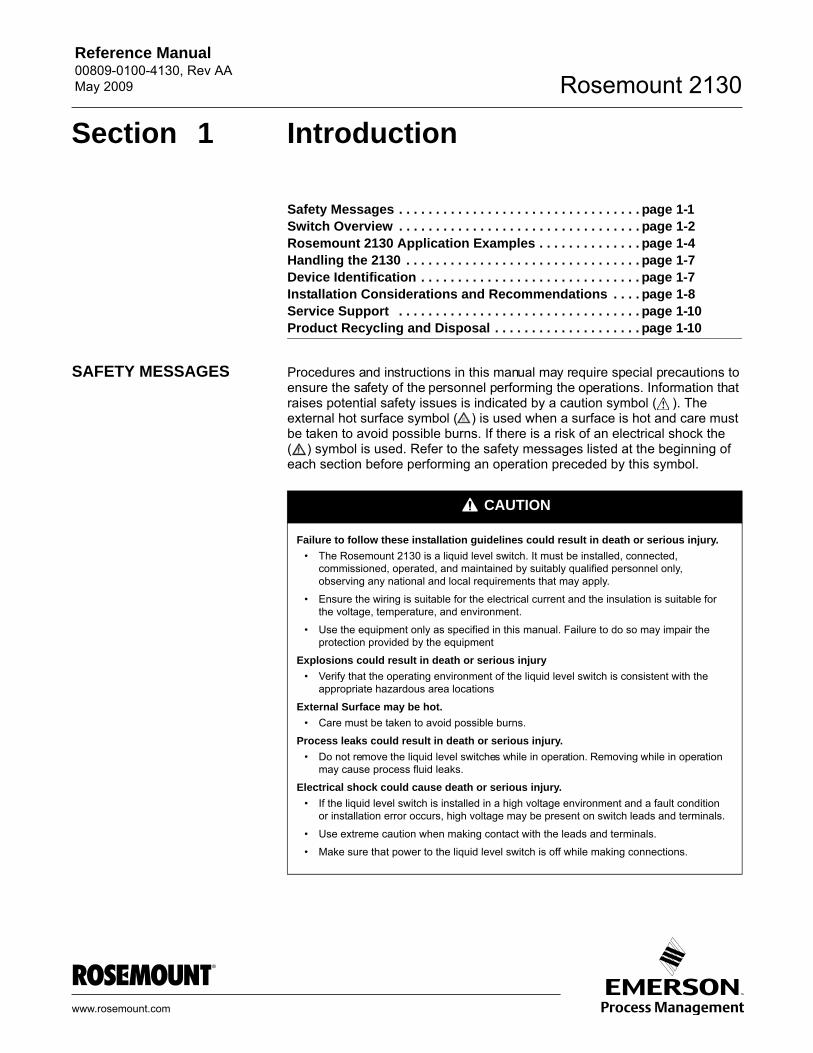
SAFETY MESSAGES Procedures and instructions in this manual may require special precautions to ensure the safety of the personnel performing the operations. Information that raises potential safety issues is indicated by a caution symbol ( ). The external hot surface symbol ( ) is used when a surface is hot and care must be taken to avoid possible burns. If there is a risk of an electrical shock the ( ) symbol is used. Refer to the safety messages listed at the beginning of each section before performing an operation preceded by this symbol.
CAUTION
Failure to follow these installation guidelines could result in death or serious injury.
• The Rosemount 2130 is a liquid level switch. It must be installed, connected, commissioned, operated, and maintained by suitably qualified personnel only, observing any national and local requirements that may apply.
• Ensure the wiring is suitable for the electrical current and the insulation is suitable for the voltage, temperature, and environment.
• Use the equipment only as specified in this manual. Failure to do so may impair the protection provided by the equipment
Explosions could result in death or serious injury
• Verify that the operating environment of the liquid level switch is consistent with the appropriate hazardous area locations
External Surface may be hot.
• Care must be taken to avoid possible burns.
Process leaks could result in death or serious injury.
• Do not remove the liquid level switches while in operation. Removing while in operation may cause process fluid leaks.
Electrical shock could cause death or serious injury.
• If the liquid level switch is installed in a high voltage environment and a fault condition or installation error occurs, high voltage may be present on switch leads and terminals.
• Use extreme caution when making contact with the leads and terminals.
• Make sure that power to the liquid level switch is off while making connections.
Reference Manual00809-0100-4130, Rev AA
May 2009Rosemount 2130
1-2
SWITCH OVERVIEW The Rosemount 2130 Extreme Temperature Vibrating Fork Level Switch is designed for use in extreme temperatures. Based on vibrating short fork technology, the 2130 is suitable for virtually all liquid applications.
Features include:• Virtually unaffected by flow, bubbles, turbulence, foam, vibration, solids
content, coating, properties of the liquid, and product variations• Operation in extreme temperatures of –94 to 500 °F (–70 to 260°C)• No need for calibration and requires minimum installation procedures • Easy terminal access, polarity insensitive, and short-circuit protection• No moving parts or crevices means virtually no maintenance• Electronic self-checking and condition monitoring. The heartbeat LED
gives status and instrument health information• Adjustable Switching Delay for turbulent or splashing applications • Magnetic test point for easy functional test• Short fork length with extensions up to 118 in. (3 m)• “Fast Drip” fork design gives quick response time• General area, Explosion-proof/Flameproof, and Intrinsically Safe
options
This combination of features makes the 2130 an ideal choice for a wide variety of challenging applications in the chemical, power generation, and oil and gas industries.
CAUTION
Any substitution of non-recognized parts may jeopardize safety and is under no circumstances allowed.
Reference Manual 00809-0100-4130, Rev AAMay 2009
1-3
Rosemount 2130
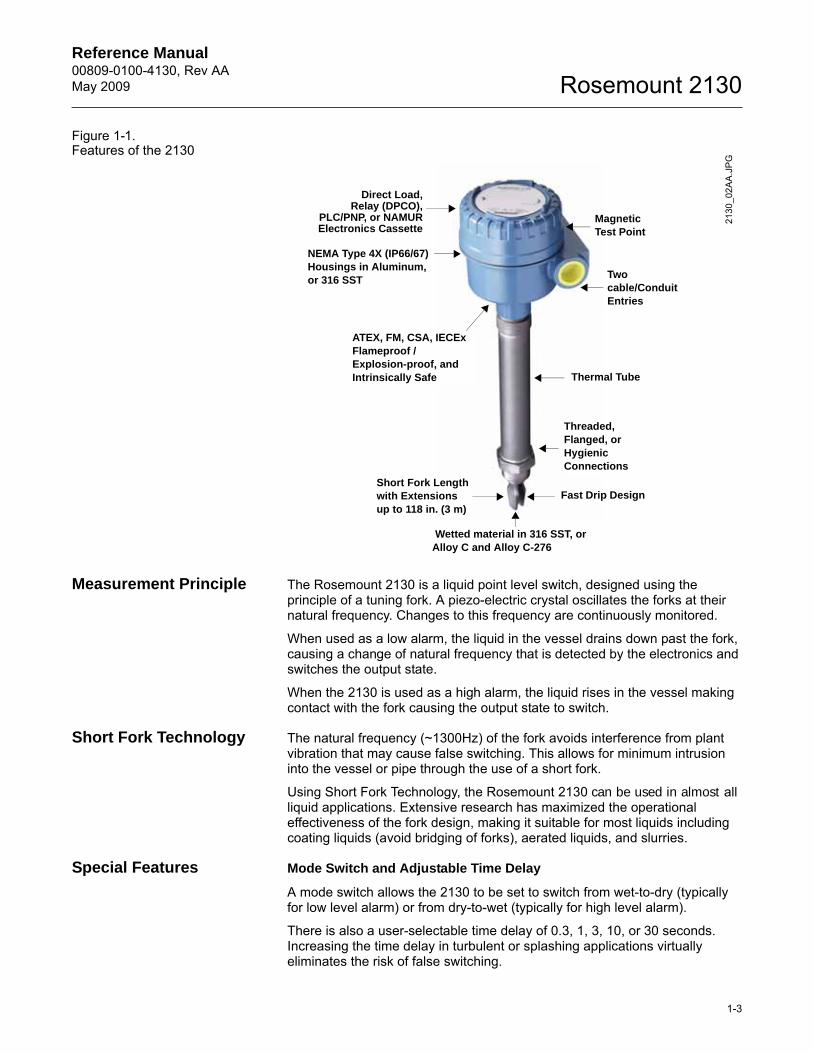
Figure 1-1. Features of the 2130
Measurement Principle The Rosemount 2130 is a liquid point level switch, designed using the principle of a tuning fork. A piezo-electric crystal oscillates the forks at their natural frequency. Changes to this frequency are continuously monitored.
When used as a low alarm, the liquid in the vessel drains down past the fork, causing a change of natural frequency that is detected by the electronics and switches the output state.
When the 2130 is used as a high alarm, the liquid rises in the vessel making contact with the fork causing the output state to switch.
Short Fork Technology The natural frequency (~1300Hz) of the fork avoids interference from plant vibration that may cause false switching. This allows for minimum intrusion into the vessel or pipe through the use of a short fork.
Using Short Fork Technology, the Rosemount 2130 can be used in almost all liquid applications. Extensive research has maximized the operational effectiveness of the fork design, making it suitable for most liquids including coating liquids (avoid bridging of forks), aerated liquids, and slurries.
Special Features Mode Switch and Adjustable Time Delay
A mode switch allows the 2130 to be set to switch from wet-to-dry (typically for low level alarm) or from dry-to-wet (typically for high level alarm).
There is also a user-selectable time delay of 0.3, 1, 3, 10, or 30 seconds. Increasing the time delay in turbulent or splashing applications virtually eliminates the risk of false switching.
Wetted material in 316 SST, or Alloy C and Alloy C-276
NEMA Type 4X (IP66/67) Housings in Aluminum, or 316 SST Two
cable/Conduit Entries
Short Fork Lengthwith Extensionsup to 118 in. (3 m)
Threaded, Flanged, orHygienicConnections
MagneticTest Point
Thermal Tube
Fast Drip Design
ATEX, FM, CSA, IECEx Flameproof /Explosion-proof, and Intrinsically Safe
2130
_02A
A.J
PG
Direct Load,Relay (DPCO),
PLC/PNP, or NAMURElectronics Cassette
Reference Manual00809-0100-4130, Rev AA
May 2009Rosemount 2130
1-4
Heartbeat LED
The 2130 has a ‘heartbeat’ LED that indicates status. The LED flashes when the switch output is ‘off’ and is constantly lit when 'on'. The LED constantly indicates that the 2130 is functioning correctly.
Magnetic Test Point
A magnetic test-point is located on the side of the housing, allowing the user to perform a functional test of the 2130 and the system connected to it.
Holding a magnet to the test-point causes the output to change state.
Instrument Health Monitor and Continuous Self-Check
The 2130 continuously performs instrument health diagnostics to self-check the condition of the fork and sensor. These diagnostics can detect damage to the forks including corrosion, internal or external damage to the forks, and breakages to the internal wiring. Any of these conditions will trigger the 'heartbeat' LED to pulse intermittently, followed by safe handling of the electrical load.
Electrical Hookup
The terminal blocks extend above the housing and give easy terminal access. The polarity insensitivity and short-circuit protection make electrical hook-up safe and easy.
Fork Design
The “fast drip” fork design draws liquid away from the fork tips, and together with a short switching delay, allows the 2130 to react quickly and with greater sensitivity to density variations.
ROSEMOUNT 2130 APPLICATION EXAMPLES
For most liquids, including coating, aerated liquids and slurries, the function is virtually unaffected by flow, turbulence, bubbles, foam, vibration, solid particles, build-up, or properties of the liquid.See Figure 1-2 on page 1-6 for application examples.
The 2130 can be used in Hazardous (IS or Exd) or non-hazardous (safe) areas but supports higher process temperatures up to 500 °F (260 °C).
The 2130 can be mounted in any position in a tank or pipe. There is a wide range of threaded, flanged, or hygienic connections.
Application Considerations:
• Ensure the process is operating within the temperature and pressure ranges (see “Specifications” on page A-1)
• Ensure the liquid viscosity is within the recommended viscosity range(see “Specifications” on page A-1)
• Check that the liquid density is higher than 37.5 lb/ft3 (600 kg/m3), or above 31.2 lb/ft3 (500 kg/m3) when ordered with the Low Density Range option (see “Specifications” on page A-1)
• Check for risk of build-up on the forksAvoid situations where drying and coating products may create excessive build-up
• Ensure there is no risk of bridging the forks
Reference Manual 00809-0100-4130, Rev AAMay 2009
1-5
Rosemount 2130
Examples of products that can create bridging of forks are dense paper slurries and bitumen
• Check the solids content in the liquidAs a guideline, the maximum solid particle diameter in the liquid is 0.2 in. (5 mm)Extra consideration is needed when dealing with particles bigger than 0.2 in. (5 mm). Consult the factory for advice.
• Problems may occur if product coats and dries causing caking.• In almost all cases, the 2130 is insensitive to foams (i.e. does not see
the foam).However in rare occasions, some very dense foams may be seen as liquid; a known example of this is found in ice-cream and orange juice manufacturing.
Reference Manual00809-0100-4130, Rev AA
May 2009Rosemount 2130
1-6
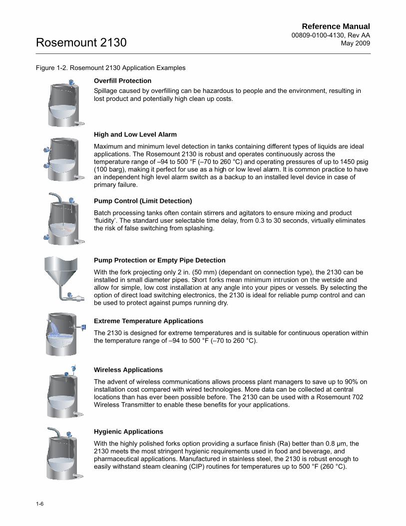
Figure 1-2. Rosemount 2130 Application Examples
Overfill Protection
Spillage caused by overfilling can be hazardous to people and the environment, resulting in lost product and potentially high clean up costs.
High and Low Level Alarm
Maximum and minimum level detection in tanks containing different types of liquids are ideal applications. The Rosemount 2130 is robust and operates continuously across the temperature range of –94 to 500 °F (–70 to 260 °C) and operating pressures of up to 1450 psig (100 barg), making it perfect for use as a high or low level alarm. It is common practice to have an independent high level alarm switch as a backup to an installed level device in case of primary failure.
Pump Control (Limit Detection)
Batch processing tanks often contain stirrers and agitators to ensure mixing and product ‘fluidity’. The standard user selectable time delay, from 0.3 to 30 seconds, virtually eliminates the risk of false switching from splashing.
Pump Protection or Empty Pipe Detection
With the fork projecting only 2 in. (50 mm) (dependant on connection type), the 2130 can be installed in small diameter pipes. Short forks mean minimum intrusion on the wetside and allow for simple, low cost installation at any angle into your pipes or vessels. By selecting the option of direct load switching electronics, the 2130 is ideal for reliable pump control and can be used to protect against pumps running dry.
Extreme Temperature Applications
The 2130 is designed for extreme temperatures and is suitable for continuous operation within the temperature range of –94 to 500 °F (–70 to 260 °C).
Wireless Applications
The advent of wireless communications allows process plant managers to save up to 90% on installation cost compared with wired technologies. More data can be collected at central locations than has ever been possible before. The 2130 can be used with a Rosemount 702 Wireless Transmitter to enable these benefits for your applications.
Hygienic Applications
With the highly polished forks option providing a surface finish (Ra) better than 0.8 µm, the 2130 meets the most stringent hygienic requirements used in food and beverage, and pharmaceutical applications. Manufactured in stainless steel, the 2130 is robust enough to easily withstand steam cleaning (CIP) routines for temperatures up to 500 °F (260 °C).
2120 Vibrating Fork Level Switch
www.rosemount.com
2120 Vibrating Fo
rk Level Switch
www.ro
semount.co
m
2120 Vibrating Fo
rk Level Switch
www.ro
semount.co
m
2120 Vibrating Fork Level Switch
www.rosemount.com
2120 Vibrating Fo
rk Level Switch
www.ro
semount.co
m
2120 Vibrating Fork Level Switch
www.rosemount.com
2120 Vibrating Fork Level Switch
www.rosemount.com
Reference Manual 00809-0100-4130, Rev AAMay 2009
1-7
Rosemount 2130
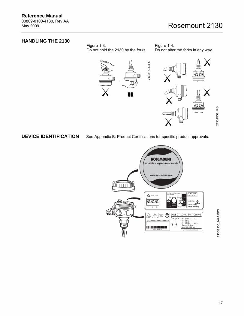
HANDLING THE 2130
DEVICE IDENTIFICATION See Appendix B: Product Certifications for specific product approvals.
Figure 1-3. Do not hold the 2130 by the forks.
Figure 1-4. Do not alter the forks in any way.
2130
/FIG
1.JP
G
2130
/FIG
2.JP
G
2130 Vibrating Fork Level Switch
www.rosemount.com
DIR E C T L OA D S WIT C HING
99500200 www .rosemount.com
MAGNETICTEST
POINT
20 - 264V ac50 - 60Hz20 - 60VdcOutput Rating:Load 20 - 500mA
~ Supply
2130##############21
30/2
130_
24A
A.E
PS
Reference Manual00809-0100-4130, Rev AA
May 2009Rosemount 2130
1-8
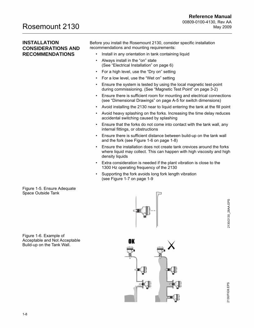
INSTALLATION CONSIDERATIONS AND RECOMMENDATIONS
Before you install the Rosemount 2130, consider specific installation recommendations and mounting requirements:
• Install in any orientation in tank containing liquid• Always install in the “on” state
(See “Electrical Installation” on page 6)• For a high level, use the “Dry on” setting• For a low level, use the “Wet on” setting• Ensure the system is tested by using the local magnetic test-point
during commissioning. (See “Magnetic Test Point” on page 3-2)• Ensure there is sufficient room for mounting and electrical connections
(see “Dimensional Drawings” on page A-5 for switch dimensions)• Avoid installing the 2130 near to liquid entering the tank at the fill point• Avoid heavy splashing on the forks. Increasing the time delay reduces
accidental switching caused by splashing• Ensure that the forks do not come into contact with the tank wall, any
internal fittings, or obstructions• Ensure there is sufficient distance between build-up on the tank wall
and the fork (see Figure 1-6 on page 1-8)• Ensure the installation does not create tank crevices around the forks
where liquid may collect. This can happen with high viscosity and high density liquids
• Extra consideration is needed if the plant vibration is close to the1300 Hz operating frequency of the 2130
• Supporting the fork avoids long fork length vibration(see Figure 1-7 on page 1-9
Figure 1-5. Ensure Adequate Space Outside Tank
Figure 1-6. Example of Acceptable and Not Acceptable Build-up on the Tank Wall.
2130
/213
0_28
AA.E
PS21
30/F
IG9.
EPS
Reference Manual 00809-0100-4130, Rev AAMay 2009
1-9
Rosemount 2130
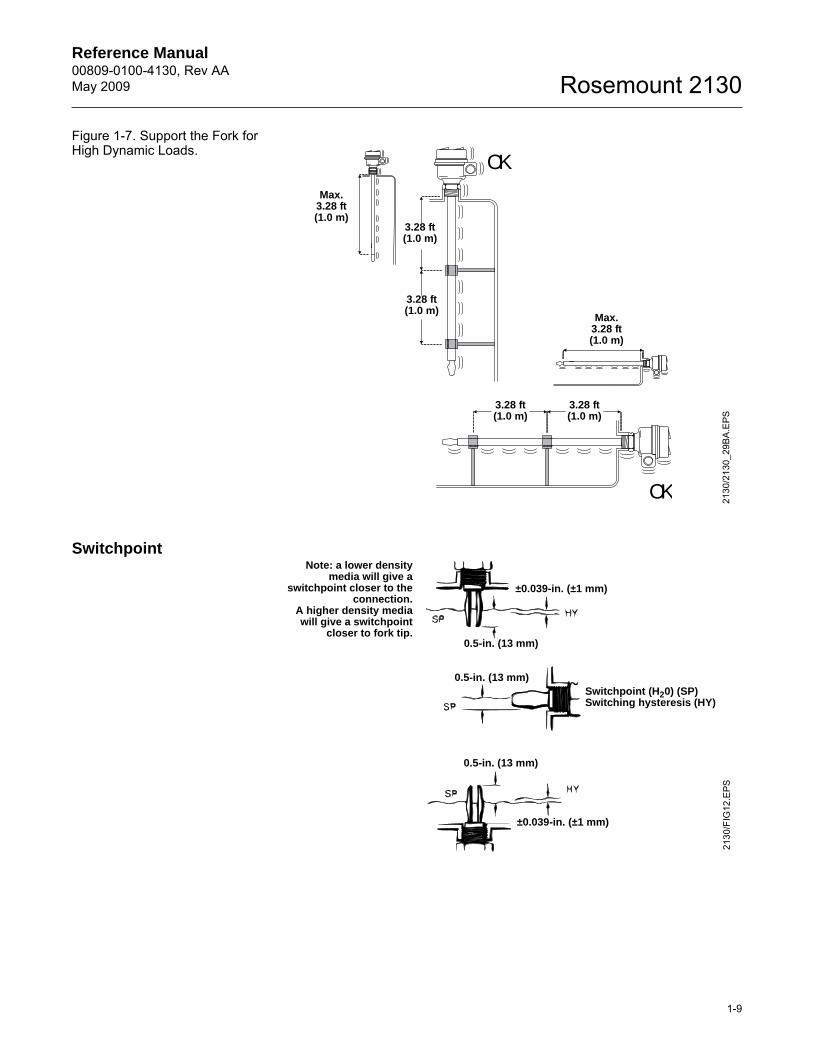
Figure 1-7. Support the Fork for High Dynamic Loads.
Switchpoint
OK
OK 2130
/213
0_29
BA.E
PS
3.28 ft (1.0 m)
3.28 ft (1.0 m)
Max. 3.28 ft (1.0 m)
3.28 ft (1.0 m)
3.28 ft (1.0 m)
Max.3.28 ft (1.0 m)
2130
/FIG
12.E
PS
Switchpoint (H20) (SP)Switching hysteresis (HY)
±0.039-in. (±1 mm)
±0.039-in. (±1 mm)
0.5-in. (13 mm)
0.5-in. (13 mm)
0.5-in. (13 mm)
Note: a lower densitymedia will give a
switchpoint closer to theconnection.
A higher density mediawill give a switchpoint
closer to fork tip.
Reference Manual00809-0100-4130, Rev AA
May 2009Rosemount 2130
1-10
SERVICE SUPPORT To expedite the return process outside of the United States, contact the nearest Emerson Process Management representative.
Within the United States, call the Emerson Process Management Instrument and Valves Response Center using the toll-free number 1-800-654-RSMT (7768). This center, available 24 hours a day, will assist you with any needed information or materials.
The center will ask for product model and serial numbers, and will provide a Return Material Authorization (RMA) number. The center will also ask for the process material the product was last exposed.
Emerson Process Management Instrument and Valves Response Center representatives will explain the additional information and procedures necessary to return goods exposed to hazardous substance can avoid injury if they are informed of and understand the hazard. If the product being returned was exposed to a hazardous substance as defined by OSHA, a copy of the required Material Safety Data Sheet (MSDS) for each hazardous substance identified must be included with the returned goods.
PRODUCT RECYCLING AND DISPOSAL
Recycling of equipment and packaging should be taken into consideration. The product and packaging should be disposed of in accordance with local and national legislation.
Reference Manual 00809-0100-4130, Rev AAMay 2009
2-1
Rosemount 2130
Section 2 Installation
Safety Messages . . . . . . . . . . . . . . . . . . . . . . . . . . . . . . . . . page 2-1Mechanical Installation . . . . . . . . . . . . . . . . . . . . . . . . . . . page 2-2Correct Fork Alignment . . . . . . . . . . . . . . . . . . . . . . . . . . . page 2-2Cable Gland Orientation . . . . . . . . . . . . . . . . . . . . . . . . . . . page 2-3Set Mode Switch / Switching Time Delay . . . . . . . . . . . . . page 2-4LED Indication . . . . . . . . . . . . . . . . . . . . . . . . . . . . . . . . . . . page 2-5Electrical Installation . . . . . . . . . . . . . . . . . . . . . . . . . . . . . page 2-6
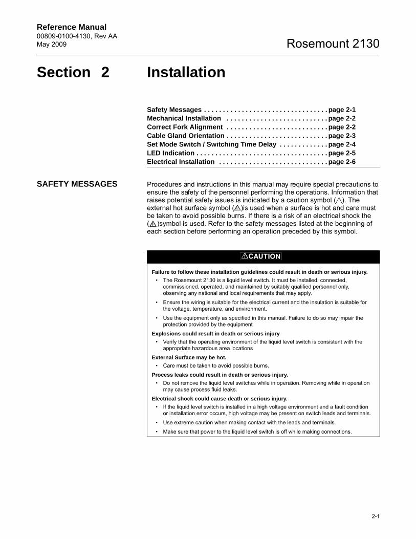
SAFETY MESSAGES Procedures and instructions in this manual may require special precautions to ensure the safety of the personnel performing the operations. Information that raises potential safety issues is indicated by a caution symbol ( ). The external hot surface symbol ( )is used when a surface is hot and care must be taken to avoid possible burns. If there is a risk of an electrical shock the ( )symbol is used. Refer to the safety messages listed at the beginning of each section before performing an operation preceded by this symbol.
Failure to follow these installation guidelines could result in death or serious injury.
• The Rosemount 2130 is a liquid level switch. It must be installed, connected, commissioned, operated, and maintained by suitably qualified personnel only, observing any national and local requirements that may apply.
• Ensure the wiring is suitable for the electrical current and the insulation is suitable for the voltage, temperature, and environment.
• Use the equipment only as specified in this manual. Failure to do so may impair the protection provided by the equipment
Explosions could result in death or serious injury
• Verify that the operating environment of the liquid level switch is consistent with the appropriate hazardous area locations
External Surface may be hot.
• Care must be taken to avoid possible burns.
Process leaks could result in death or serious injury.
• Do not remove the liquid level switches while in operation. Removing while in operation may cause process fluid leaks.
Electrical shock could cause death or serious injury.
• If the liquid level switch is installed in a high voltage environment and a fault condition or installation error occurs, high voltage may be present on switch leads and terminals.
• Use extreme caution when making contact with the leads and terminals.
• Make sure that power to the liquid level switch is off while making connections.
Reference Manual00809-0100-4130, Rev AA
May 2009Rosemount 2130
2-2
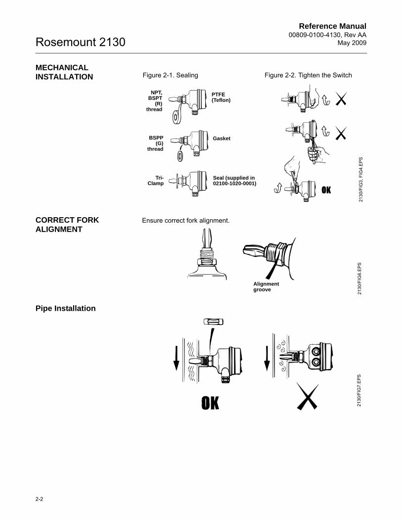
MECHANICAL INSTALLATION
CORRECT FORK ALIGNMENT
Ensure correct fork alignment.
Pipe Installation
Figure 2-1. Sealing Figure 2-2. Tighten the Switch
PTFE (Teflon)
Gasket
Seal (supplied in 02100-1020-0001)
NPT,BSPT
(R)thread
BSPP(G)
thread
Tri-Clamp
2130
/FIG
3, F
IG4.
EPS
2130
/FIG
6.EP
S
Alignment groove
2130
/FIG
7.E
PS
Reference Manual 00809-0100-4130, Rev AAMay 2009
2-3
Rosemount 2130
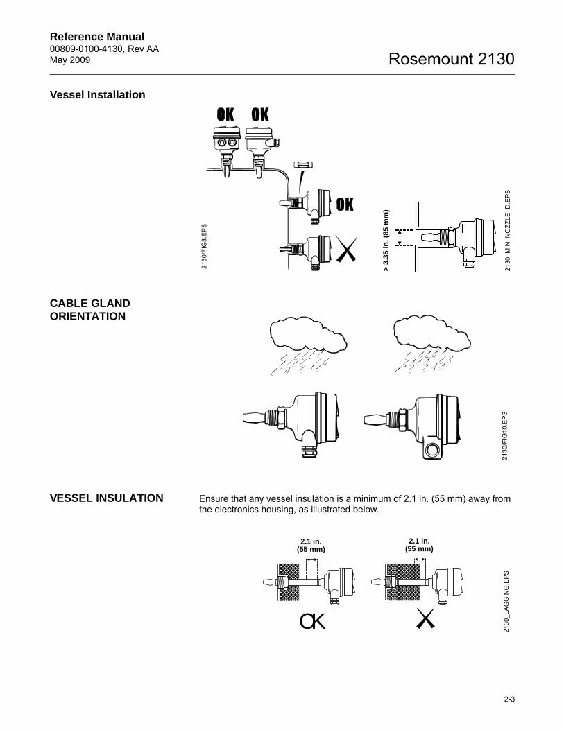
Vessel Installation
CABLE GLAND ORIENTATION
VESSEL INSULATION Ensure that any vessel insulation is a minimum of 2.1 in. (55 mm) away from the electronics housing, as illustrated below.
2130
/FIG
8.E
PS
> 3
.35
in. (
85 m
m)
2130
_MIN
_NO
ZZLE
_D.E
PS21
30/F
IG10
.EPS
OK 2130
_LA
GG
ING
.EPS
2.1 in.(55 mm)
2.1 in.(55 mm)
Reference Manual00809-0100-4130, Rev AA
May 2009Rosemount 2130
2-4
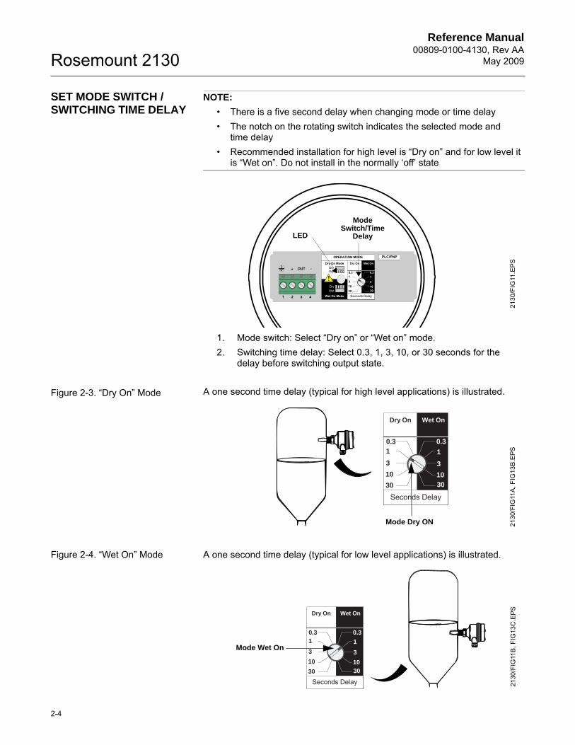
SET MODE SWITCH / SWITCHING TIME DELAY
NOTE:
• There is a five second delay when changing mode or time delay• The notch on the rotating switch indicates the selected mode and
time delay• Recommended installation for high level is “Dry on” and for low level it
is “Wet on”. Do not install in the normally ‘off’ state
1. Mode switch: Select “Dry on” or “Wet on” mode.2. Switching time delay: Select 0.3, 1, 3, 10, or 30 seconds for the
delay before switching output state.
Figure 2-3. “Dry On” Mode A one second time delay (typical for high level applications) is illustrated.
Figure 2-4. “Wet On” Mode A one second time delay (typical for low level applications) is illustrated.
OPERATION MODE
Dry On ModeDryWet
Wet On Mode
DryWet
Dry On Wet On
Seconds Delay
0.3 0.3
3
3010
1
3
3010
1
1 2 3
OUT+ -
4
PLC/PNP
2130
/FIG
11.E
PS
Mode Switch/Time
DelayLED
Dry On Wet On
Seconds Delay
0.3 0.3
3
30
10
1
3
3010
1
Mode Dry ON 2130
/FIG
11A
, FIG
13B
.EPS
Dry On Wet On
Seconds Delay
0.3 0.3
30
10
3
3010
1
3
1
2130
/FIG
11B
, FIG
13C
.EPS
Mode Wet On
Reference Manual 00809-0100-4130, Rev AAMay 2009
2-5
Rosemount 2130
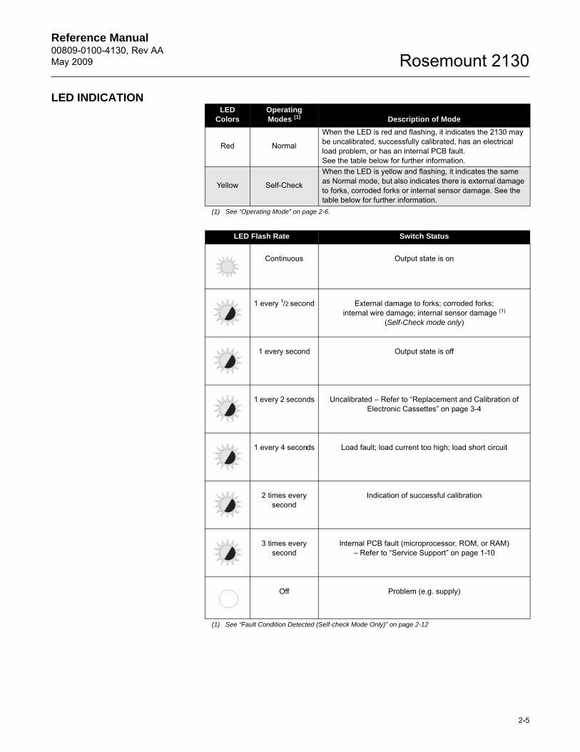
LED INDICATIONLED
ColorsOperatingModes (1)
(1) See “Operating Mode” on page 2-6.
Description of Mode
Red Normal
When the LED is red and flashing, it indicates the 2130 may be uncalibrated, successfully calibrated, has an electrical load problem, or has an internal PCB fault.See the table below for further information.
Yellow Self-Check
When the LED is yellow and flashing, it indicates the same as Normal mode, but also indicates there is external damage to forks, corroded forks or internal sensor damage. See the table below for further information.
LED Flash Rate Switch Status
Continuous Output state is on
1 every 1/2 second External damage to forks; corroded forks;internal wire damage; internal sensor damage (1)
(Self-Check mode only)
(1) See “Fault Condition Detected (Self-check Mode Only)” on page 2-12
1 every second Output state is off
1 every 2 seconds Uncalibrated – Refer to “Replacement and Calibration of Electronic Cassettes” on page 3-4
1 every 4 seconds Load fault; load current too high; load short circuit
2 times every second
Indication of successful calibration
3 times every second
Internal PCB fault (microprocessor, ROM, or RAM)– Refer to “Service Support” on page 1-10
Off Problem (e.g. supply)
Reference Manual00809-0100-4130, Rev AA
May 2009Rosemount 2130
2-6
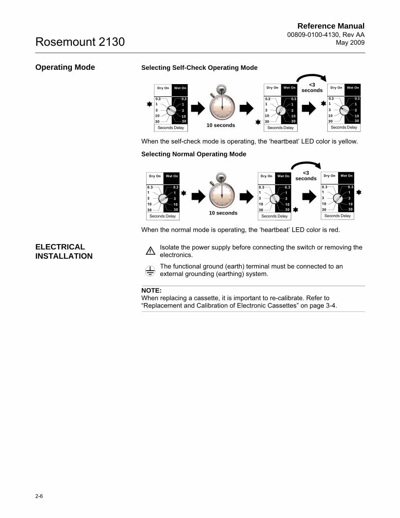
Operating Mode Selecting Self-Check Operating Mode
When the self-check mode is operating, the ‘heartbeat’ LED color is yellow.
Selecting Normal Operating Mode
When the normal mode is operating, the ‘heartbeat’ LED color is red.
ELECTRICAL INSTALLATION
Isolate the power supply before connecting the switch or removing the electronics.
The functional ground (earth) terminal must be connected to an external grounding (earthing) system.
NOTE:When replacing a cassette, it is important to re-calibrate. Refer to “Replacement and Calibration of Electronic Cassettes” on page 3-4.
Dry On Wet On
Seconds Delay
0.3 0.3
3
30
10
1
3
3010
1
Dry On Wet On
Seconds Delay
0.3 0.3
3
30
10
1
3
30
10
1
Dry On Wet On
Seconds Delay
0.3 0.3
3
30
10
1
3
3010
1
10 seconds
<3seconds
Dry On Wet On
Seconds Delay
0.3 0.3
3
3010
13
3010
1
Dry On Wet On
Seconds Delay
0.3 0.3
3
3010
13
3010
1
Dry On Wet On
Seconds Delay
0.3 0.3
3
3010
13
3010
1
10 seconds
<3seconds
Reference Manual 00809-0100-4130, Rev AAMay 2009
2-7
Rosemount 2130
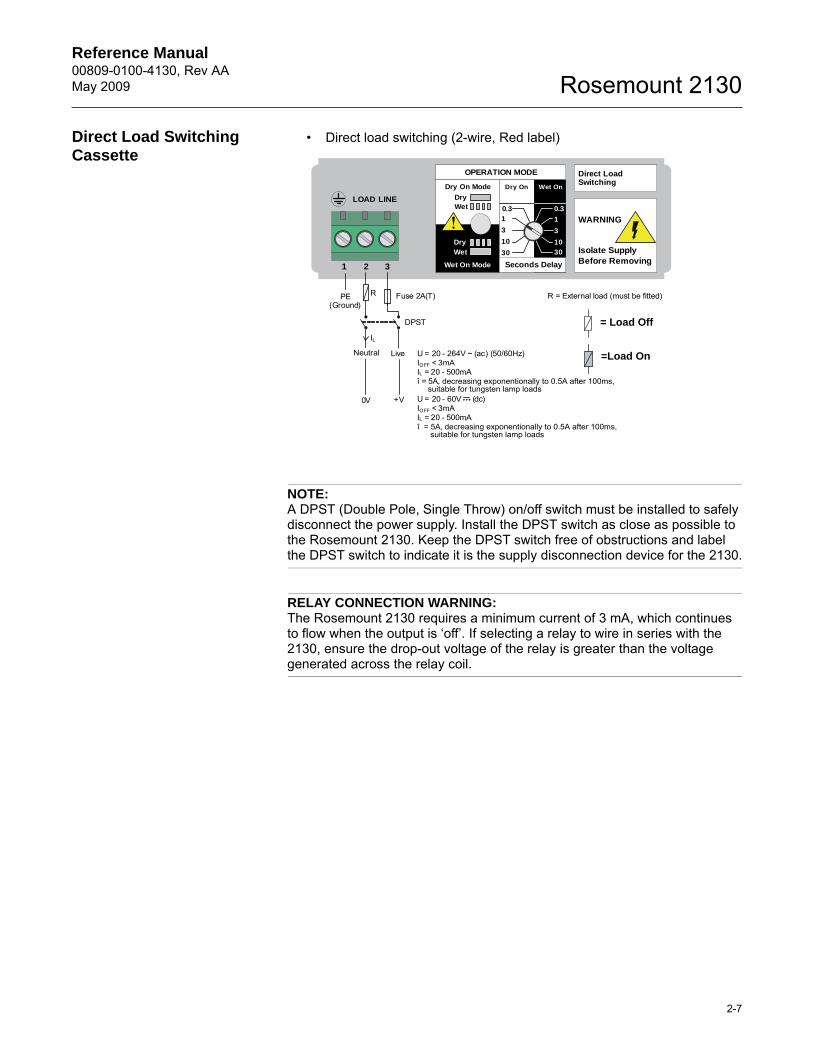
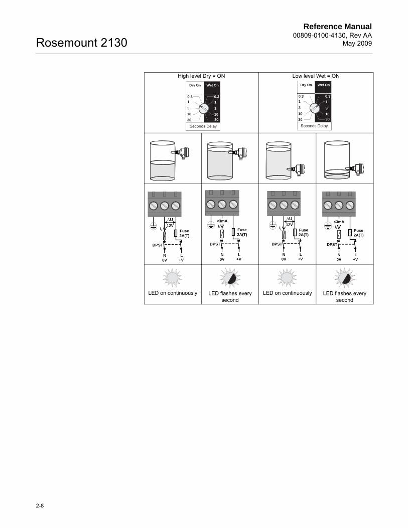
Direct Load Switching Cassette
• Direct load switching (2-wire, Red label)
NOTE:A DPST (Double Pole, Single Throw) on/off switch must be installed to safely disconnect the power supply. Install the DPST switch as close as possible to the Rosemount 2130. Keep the DPST switch free of obstructions and label the DPST switch to indicate it is the supply disconnection device for the 2130.
RELAY CONNECTION WARNING:The Rosemount 2130 requires a minimum current of 3 mA, which continues to flow when the output is ‘off’. If selecting a relay to wire in series with the 2130, ensure the drop-out voltage of the relay is greater than the voltage generated across the relay coil.
Direct LoadSwitching
WARNING
Isolate SupplyBefore Removing
OPERATION MODE
Dry On Mode
DryWet
Wet On Mode
Dry
Wet
Dry On Wet On
Seconds Delay
0.3 0.3
3
30
10
1
3
30
10
1
1 2 3
LINELOAD
PE(Ground)
Neutral Live
0V +V
Fuse 2A(T)R
IL
R = External load (must be fitted)
U = 20 - 264V ~ (ac) (50/60Hz)IOFF < 3mAIL = 20 - 500mAî = 5A, decreasing exponentionally to 0.5A after 100ms,
U = 20 - 60V (dc)IOFF < 3mAIL = 20 - 500mAî =
DPST
suitable for tungsten lamp loads
5A, decreasing exponentionally to 0.5A after 100ms,suitable for tungsten lamp loads
=Load On
= Load Off
Reference Manual00809-0100-4130, Rev AA
May 2009Rosemount 2130
2-8
High level Dry = ON Low level Wet = ON
LED on continuously LED flashes every second
LED on continuously LED flashes every second
Dry On Wet On
Seconds Delay
0.3 0.3
3
30
10
1
3
3010
1
Dry On Wet On
Seconds Delay
0.3 0.3
30
10
3
3010
1
3
1
U
N L0V +V
Fuse2A(T)
IL
12V
DPST
Fuse2A(T)
N L0V +V
IL
<3mA
DPST
U
N L0V +V
Fuse2A(T)
IL
12V
DPST
Fuse2A(T)
N L0V +V
IL
<3mA
DPST
Reference Manual 00809-0100-4130, Rev AAMay 2009
2-9
Rosemount 2130
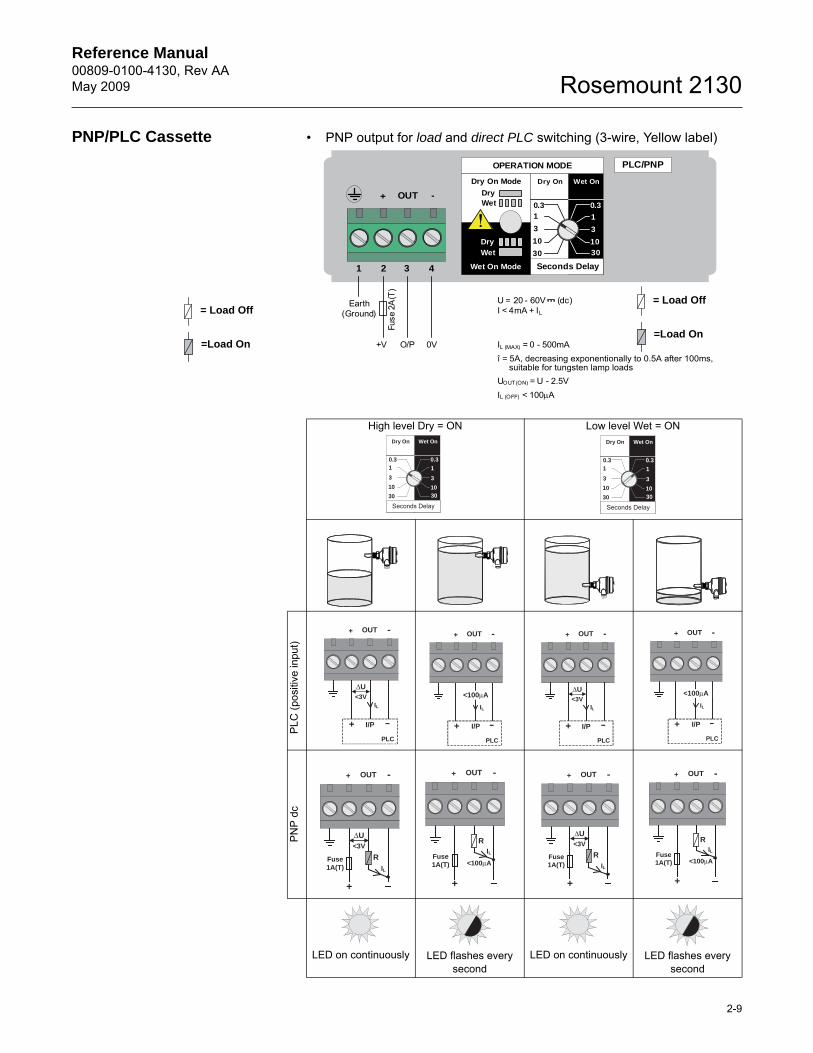
PNP/PLC Cassette • PNP output for load and direct PLC switching (3-wire, Yellow label)
High level Dry = ON Low level Wet = ON
PLC
(pos
itive
inpu
t)P
NP
dc
LED on continuously LED flashes every second
LED on continuously LED flashes every second
OPERATION MODE
Dry On Mode
DryWet
Wet On Mode
Dry
Wet
Dry On Wet On
Seconds Delay
0.3 0.3
3
30
10
1
3
30
10
1
1 2 3
OUT+ -
4
PLC/PNP
Earth(Ground)
0V+V O/P
U = 20 - 60V (dc)I < 4mA + IL
IL (MAX) = 0 - 500mAî = 5A, decreasing exponentionally to 0.5A after 100ms,
UOUT(ON) = U - 2.5VIL (OFF) < 100A
Fuse
2A
(T)
suitable for tungsten lamp loads
=Load On
= Load Off
Dry On Wet On
Seconds Delay
0.3 0.3
3
30
10
1
3
3010
1
Dry On Wet On
Seconds Delay
0.3 0.3
30
10
3
3010
1
3
1
OUT -+
PLC
+ I/P
ΔU<3V
IL
OUT -+
PLC
+ I/P
IL
<100μA
OUT -+
PLC
+ I/P
ΔU<3V
IL
OUT -+
PLC
+ I/P
IL
<100μA
OUT -+
+
ΔU<3V
IL
Fuse1A(T)
R
OUT -+
+
ILFuse1A(T)
R
<100μA
OUT -+
+
ΔU<3V
IL
Fuse1A(T)
R
OUT -+
+
ILFuse1A(T)
R
<100μA
=Load On
= Load Off
Reference Manual00809-0100-4130, Rev AA
May 2009Rosemount 2130
2-10
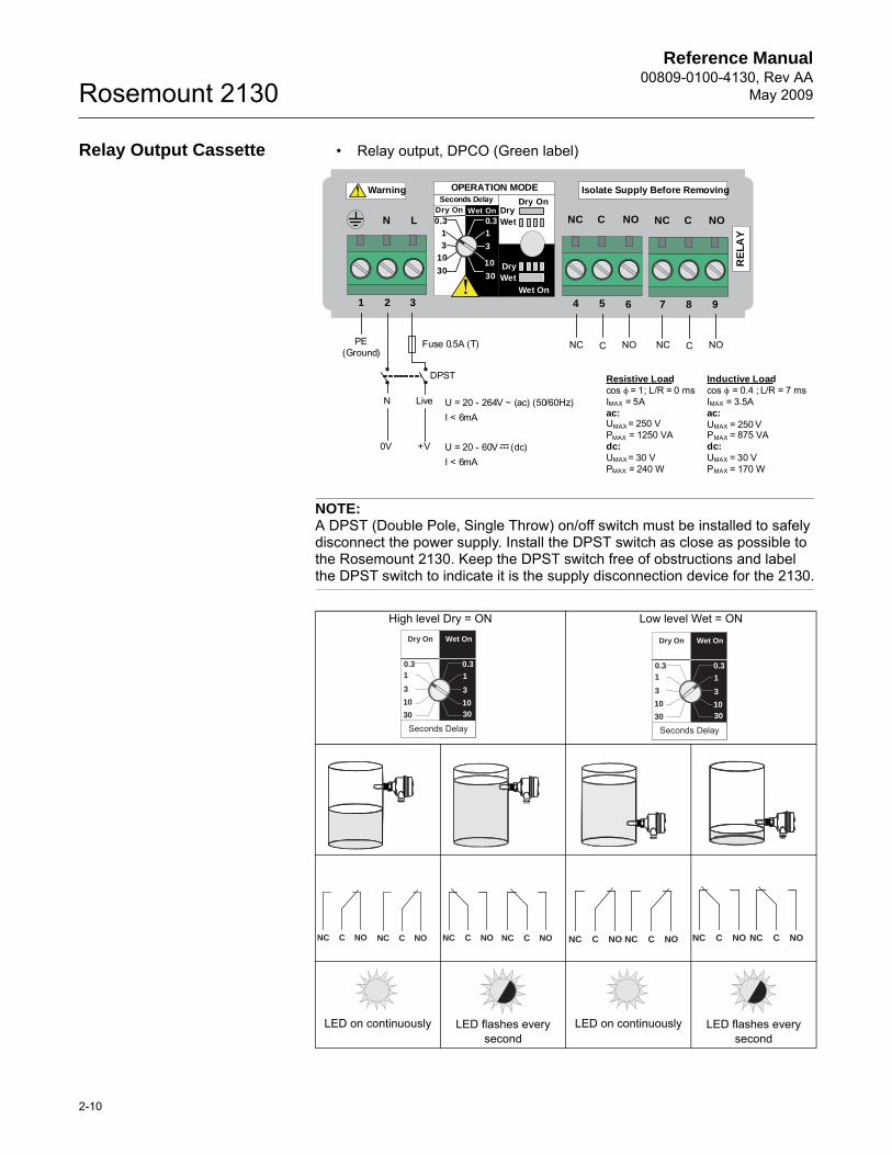
Relay Output Cassette • Relay output, DPCO (Green label)
NOTE:A DPST (Double Pole, Single Throw) on/off switch must be installed to safely disconnect the power supply. Install the DPST switch as close as possible to the Rosemount 2130. Keep the DPST switch free of obstructions and label the DPST switch to indicate it is the supply disconnection device for the 2130.
High level Dry = ON Low level Wet = ON
LED on continuously LED flashes every second
LED on continuously LED flashes every second
7 8 9
NOCNC
RE
LA
Y
1 2 3
LN
PE(Ground)
N
0V
Fuse 0.5A (T)
Live
+V
U = 20 - 264V ~ (ac) (50/60Hz)I < 6mA
U = 20 - 60V (dc)I < 6mA
NC C NO
DPST
4 5 6
NOCNC
NC NO
OPERATION MODE
Dry OnDryWet
Wet On
DryWet
Dry On Wet On
Seconds Delay
30
10
3
1
0.3 0.3
30
103
1
Isolate Supply Before Removing Warning
C
Resistive Loadcos φ = 1; L/R = 0 msIMAX = 5Aac:UMAX = 250 VPMAX = 1250 VAdc:UMAX = 30 VPMAX = 240 W
Inductive Loadcos φ = 0.4 ; L/R = 7 msIMAX = 3.5Aac:UMAX = 250 VPMAX = 875 VAdc:UMAX = 30 VPMAX = 170 W
Dry On Wet On
Seconds Delay
0.3 0.3
3
30
10
1
3
3010
1
Dry On Wet On
Seconds Delay
0.3 0.3
30
10
3
3010
1
3
1
NC NOC NC NOC NC NOC NC NOC NC NOC NC NOC NC NOC NC NOC
Reference Manual 00809-0100-4130, Rev AAMay 2009
2-11
Rosemount 2130
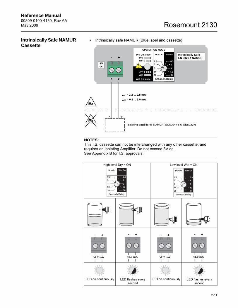
Intrinsically Safe NAMUR Cassette
• Intrinsically safe NAMUR (Blue label and cassette)
NOTES:This I.S. cassette can not be interchanged with any other cassette, and requires an Isolating Amplifier. Do not exceed 8V dc.See Appendix B for I.S. approvals.
High level Dry = ON Low level Wet = ON
LED on continuously LED flashes every second
LED on continuously LED flashes every second
OPERATION MODE
Dry On ModeDryWet
Wet On Mode
DryWet
Dry On Wet On
Seconds Delay
0.3 0.3
3
30
10
1
3
3010
1
1 2
+-Intrinsically SafeEN 50227/ NAMUR
ION = 2.2 ... 2.5 mA
IOFF = 0.8 ... 1.0 mA
+-
Isolating amplifier to NAMUR (IEC60947-5-6, EN50227)
Ex
Ex
8Vdc
Dry On Wet On
Seconds Delay
0.3 0.3
3
30
10
1
3
3010
1
Dry On Wet On
Seconds Delay
0.3 0.3
30
10
3
3010
1
3
1
+-
>2.2 mA
+-
<1.0 mA
+-
>2.2 mA
+-
<1.0 mA
Reference Manual00809-0100-4130, Rev AA
May 2009Rosemount 2130
2-12
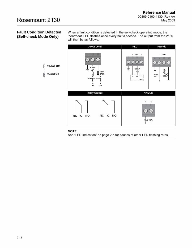
Fault Condition Detected (Self-check Mode Only)
When a fault condition is detected in the self-check operating mode, the ‘heartbeat’ LED flashes once every half a second. The output from the 2130 will then be as follows:
NOTE:See “LED Indication” on page 2-5 for causes of other LED flashing rates.
Direct Load PLC PNP dc
Relay Output NAMUR
Fuse2A(T)
N L0V +V
IL
<3mA
DPST
OUT -+
PLC
+ I/P
IL
<100μA
OUT -+
+
ILFuse1A(T)
R
<100μA
NC NOC NC NOC
+-
<1.0 mA
=Load On
= Load Off
Reference Manual 00809-0100-4130, Rev AAMay 2009 Rosemount 2130
www.rosemount.com
Section 3 Service and Troubleshooting
Safety Messages . . . . . . . . . . . . . . . . . . . . . . . . . . . . . . . . . page 3-1Magnetic Test Point . . . . . . . . . . . . . . . . . . . . . . . . . . . . . . page 3-2Inspection . . . . . . . . . . . . . . . . . . . . . . . . . . . . . . . . . . . . . . page 3-2Maintenance . . . . . . . . . . . . . . . . . . . . . . . . . . . . . . . . . . . . page 3-3Troubleshooting . . . . . . . . . . . . . . . . . . . . . . . . . . . . . . . . . page 3-3Spare Parts . . . . . . . . . . . . . . . . . . . . . . . . . . . . . . . . . . . . . page 3-3Replacement and Calibration of Electronic Cassettes . . page 3-4
SAFETY MESSAGES Procedures and instructions in this manual may require special precautions to ensure the safety of the personnel performing the operations. Information that raises potential safety issues is indicated by a caution symbol ( ). The external hot surface symbol ( ) is used when a surface is hot and care must be taken to avoid possible burns. If there is a risk of an electrical shock the ( ) symbol is used. Refer to the safety messages listed at the beginning of each section before performing an operation preceded by this symbol.
Failure to follow these installation guidelines could result in death or serious injury
• The Rosemount 2130 is a liquid level switch. It must be installed, connected, commissioned, operated, and maintained by suitably qualified personnel only, observing any national and local requirements that may apply.
• Ensure the wiring is suitable for the electrical current and the insulation is suitable for the voltage, temperature, and environment.
• Use the equipment only as specified in this manual. Failure to do so may impair the protection provided by the equipment
Explosions could result in death or serious injury
• Verify that the operating environment of the liquid level switch is consistent with the appropriate hazardous area locations
External Surface may be hot.
• Care must be taken to avoid possible burns.
Process leaks could result in death or serious injury
• Do not remove the liquid level switches while in operation. Removing while in operation may cause process fluid leaks.
Electrical shock could cause death or serious injury
• If the liquid level switch is installed in a high voltage environment and a fault condition or installation error occurs, high voltage may be present on switch leads and terminals.
• Use extreme caution when making contact with the leads and terminals.
• Make sure that power to the liquid level switch is off while making connections.
Reference Manual00809-0100-4130, Rev AA
May 2009Rosemount 2130
3-2
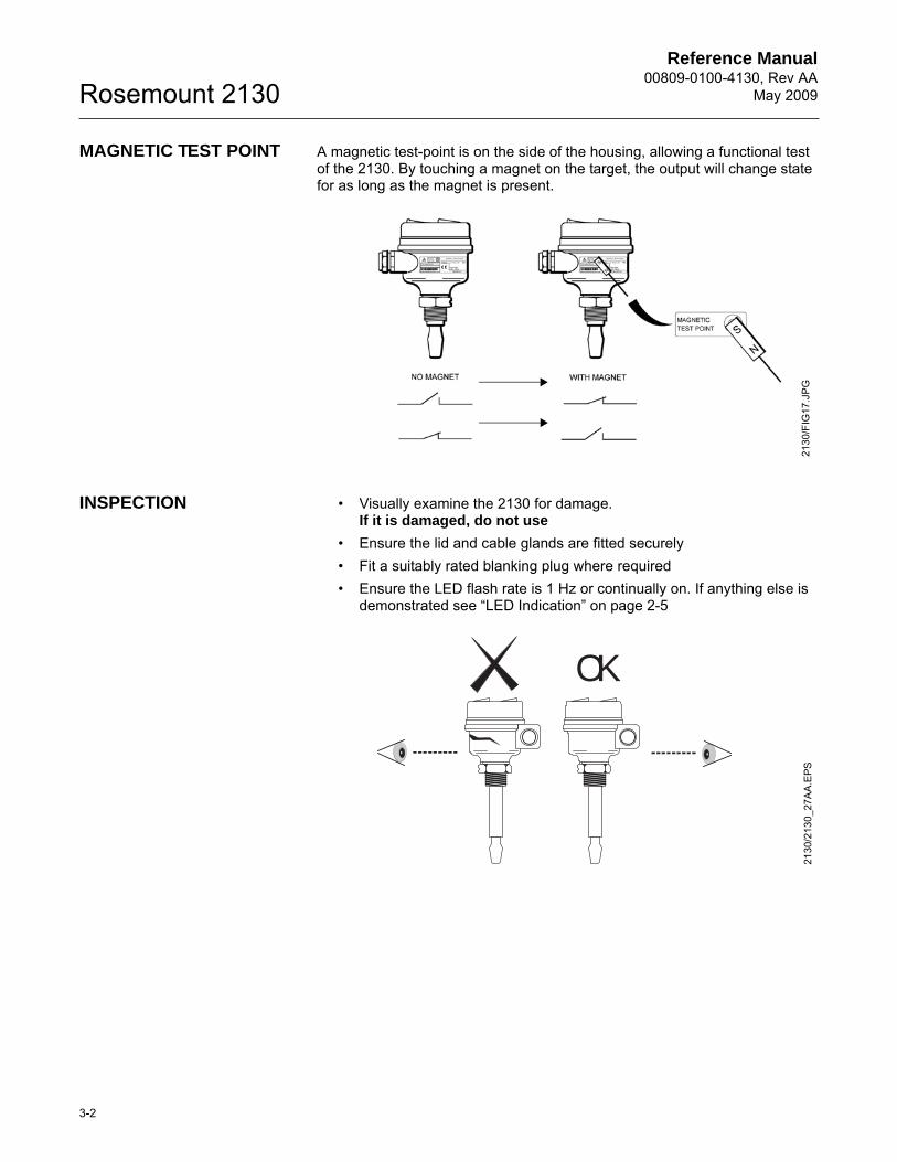
MAGNETIC TEST POINT A magnetic test-point is on the side of the housing, allowing a functional test of the 2130. By touching a magnet on the target, the output will change state for as long as the magnet is present.
INSPECTION • Visually examine the 2130 for damage.If it is damaged, do not use
• Ensure the lid and cable glands are fitted securely• Fit a suitably rated blanking plug where required• Ensure the LED flash rate is 1 Hz or continually on. If anything else is
demonstrated see “LED Indication” on page 2-5
2130
/FIG
17.J
PG
OK
2130
/213
0_27
AA
.EPS
Reference Manual 00809-0100-4130, Rev AAMay 2009
3-3
Rosemount 2130
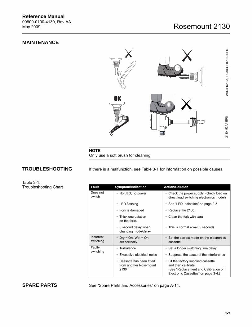
MAINTENANCE
NOTEOnly use a soft brush for cleaning.
TROUBLESHOOTING If there is a malfunction, see Table 3-1 for information on possible causes.
Table 3-1. Troubleshooting Chart
SPARE PARTS See “Spare Parts and Accessories” on page A-14.
2130
/FIG
18A
, FIG
18B,
FIG
18C
.EPS
2130
_52A
A.E
PS
Fault Symptom/Indication Action/Solution
Does not switch
• No LED; no power • Check the power supply; (check load on direct load switching electronics model)
• LED flashing • See “LED Indication” on page 2-5
• Fork is damaged • Replace the 2130
• Thick encrustationon the forks
• Clean the fork with care
• 5 second delay when changing mode/delay
• This is normal – wait 5 seconds
Incorrect switching
• Dry = On, Wet = Onset correctly
• Set the correct mode on the electronics cassette
Faultyswitching
• Turbulence • Set a longer switching time delay
• Excessive electrical noise • Suppress the cause of the interference
• Cassette has been fitted from another Rosemount 2130
• Fit the factory supplied cassetteand then calibrate.(See “Replacement and Calibration of Electronic Cassettes” on page 3-4.)
Reference Manual00809-0100-4130, Rev AA
May 2009Rosemount 2130
3-4
REPLACEMENT AND CALIBRATION OF ELECTRONIC CASSETTES
When replacing a damaged or faulty electronic cassette, calibrate the replacement cassette to the operating frequency of the fork assembly.
This section describes what is required for calibration. Calibration sequence steps 3 to 13 are time dependent and must be carried out within the noted times. The purpose of the time dependency and switching sequence is to prevent an accidental calibration from occurring.
If this replacement is taking place in a hazardous area, only qualified personnel should perform the replacement. All work in hazardous areas must be carried out in accordance with the local code. For general hazardous area requirements of this equipment, refer to Appendix B: Product Certifications.
Calibration of the device is complex and it may take several attempts before calibration is successful.
Replacement Sequence On Intrinsically Safe (I.S.) approved versions of the 2130, it is recommended that replacement and calibration be performed in a non-hazardous (safe) area.
NOTE:
• I.S. cassettes can only be replaced with I.S. cassettes• Non-I.S. cassette types can be interchanged with other non-I.S.
cassettes, but a new label must be fitted and the original part number transferred to the new label
• Before starting the replacement and calibration procedure, ensure that any controlled process will not be adversely affected
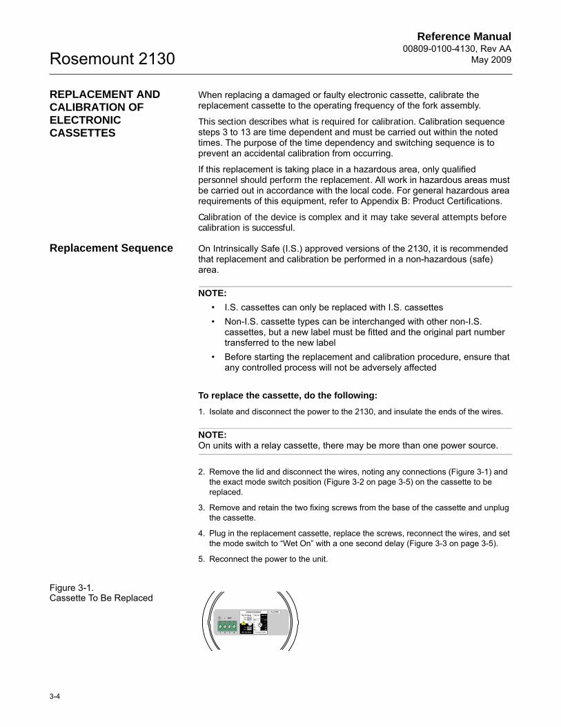
To replace the cassette, do the following:
1. Isolate and disconnect the power to the 2130, and insulate the ends of the wires.
NOTE:On units with a relay cassette, there may be more than one power source.
2. Remove the lid and disconnect the wires, noting any connections (Figure 3-1) and the exact mode switch position (Figure 3-2 on page 3-5) on the cassette to be replaced.
3. Remove and retain the two fixing screws from the base of the cassette and unplug the cassette.
4. Plug in the replacement cassette, replace the screws, reconnect the wires, and set the mode switch to “Wet On” with a one second delay (Figure 3-3 on page 3-5).
5. Reconnect the power to the unit.
Figure 3-1. Cassette To Be Replaced
OPERATION MODE
Dry On ModeDryWet
Wet On Mode
DryWet
Dry On Wet On
Seconds Delay
0.3 0.3
3
3010
1
3
3010
1
1 2 3
OUT+ -
4
PLC/PNP
Reference Manual 00809-0100-4130, Rev AAMay 2009
3-5
Rosemount 2130
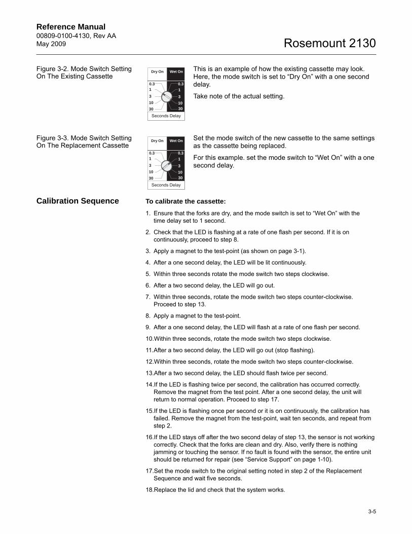
Figure 3-2. Mode Switch Setting On The Existing Cassette
This is an example of how the existing cassette may look. Here, the mode switch is set to “Dry On” with a one second delay.
Take note of the actual setting.
Figure 3-3. Mode Switch Setting On The Replacement Cassette
Set the mode switch of the new cassette to the same settings as the cassette being replaced.
For this example. set the mode switch to “Wet On” with a one second delay.
Calibration Sequence To calibrate the cassette:
1. Ensure that the forks are dry, and the mode switch is set to “Wet On” with thetime delay set to 1 second.
2. Check that the LED is flashing at a rate of one flash per second. If it is on continuously, proceed to step 8.
3. Apply a magnet to the test-point (as shown on page 3-1).
4. After a one second delay, the LED will be lit continuously.
5. Within three seconds rotate the mode switch two steps clockwise.
6. After a two second delay, the LED will go out.
7. Within three seconds, rotate the mode switch two steps counter-clockwise. Proceed to step 13.
8. Apply a magnet to the test-point.
9. After a one second delay, the LED will flash at a rate of one flash per second.
10.Within three seconds, rotate the mode switch two steps clockwise.
11.After a two second delay, the LED will go out (stop flashing).
12.Within three seconds, rotate the mode switch two steps counter-clockwise.
13.After a two second delay, the LED should flash twice per second.
14.If the LED is flashing twice per second, the calibration has occurred correctly. Remove the magnet from the test point. After a one second delay, the unit will return to normal operation. Proceed to step 17.
15.If the LED is flashing once per second or it is on continuously, the calibration has failed. Remove the magnet from the test-point, wait ten seconds, and repeat from step 2.
16.If the LED stays off after the two second delay of step 13, the sensor is not working correctly. Check that the forks are clean and dry. Also, verify there is nothing jamming or touching the sensor. If no fault is found with the sensor, the entire unit should be returned for repair (see “Service Support” on page 1-10).
17.Set the mode switch to the original setting noted in step 2 of the Replacement Sequence and wait five seconds.
18.Replace the lid and check that the system works.
Dry On Wet On
Seconds Delay
0.3 0.3
3
30
10
1
3
3010
1
Dry On Wet On
Seconds Delay
0.3 0.3
30
10
3
3010
1
3
1

Reference Manual00809-0100-4130, Rev AA
May 2009Rosemount 2130
3-6
Reference Manual 00809-0100-4130, Rev AAMay 2009 Rosemount 2130
www.rosemount.com
APPENDIX A REFERENCE DATA
Specifications . . . . . . . . . . . . . . . . . . . . . . . . . . . . . . . . . . . page A-1Dimensional Drawings . . . . . . . . . . . . . . . . . . . . . . . . . . . . page A-5Ordering Information . . . . . . . . . . . . . . . . . . . . . . . . . . . . . page A-11
SPECIFICATIONS
Physical Product• Rosemount 2130 Extreme Temperature Vibrating Fork Liquid Level Switch
Measuring Principle• Vibrating Fork
Applications• Most liquids including coating liquids, aerated liquids, and slurries
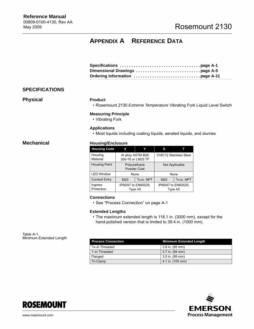
Mechanical Housing/Enclosure
Connections• See “Process Connection” on page A-1
Extended Lengths• The maximum extended length is 118.1 in. (3000 mm), except for the
hand-polished version that is limited to 39.4 in. (1000 mm).
Table A-1. Minimum Extended Length
Housing Code X Y S T
Housing Material
Al alloy ASTM B26 356-T6 or LM25 TF
316C12 Stainless Steel
Housing Paint PolyurethanePowder Coat
Not Applicable
LED Window None NoneConduit Entry M20 3/4-in. NPT M20 3/4-in. NPTIngress Protection
IP66/67 to EN60529, Type 4X
IP66/67 to EN60529,Type 4X
Process Connection Minimum Extended Length3/4–in Threaded 3.8 in. (95 mm)1–in Threaded 3.7 in. (94 mm)Flanged 3.5 in. (89 mm)Tri-Clamp 4.1 in. (105 mm)
Reference Manual00809-0100-4130, Rev AA
May 2009Rosemount 2130
A-2
Process Material• 316L Stainless Steel (1.4404), or
Alloy C (UNS N10002) and Alloy C-276 (UNS N10276)• Hand-polished to better than 0.8 m
– option available for hygienic connections• Gasket material for 3/4-in. and 1-in. BSPP (G) is non-asbestos BS7531
Grade X carbon fiber with rubber binder.
Dimensional Drawings• See “Dimensional Drawings” on page A-5.
Performance Hysteresis (Water)• ±0.039 in. (± 1 mm) nominal
Switching Point (Water)• 0.5 in. (13 mm) from tip of fork (if vertical installation) or from edge of fork
(if horizontal installation) – this will vary with different liquid densities
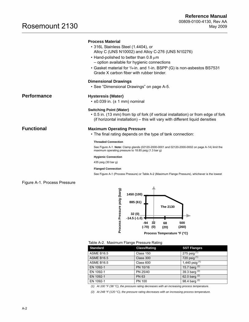
Functional Maximum Operating Pressure• The final rating depends on the type of tank connection:
Threaded Connection
See Figure A-1. Note: Clamp glands (02120-2000-0001 and 02120-2000-0002 on page A-14) limit the maximum operating pressure to 18.85 psig (1.3 bar g)
Hygienic Connection
435 psig (30 bar g)
Flanged Connection
See Figure A-1 (Process Pressure) or Table A-2 (Maximum Flange Pressure), whichever is the lowest
Figure A-1. Process Pressure
Table A-2. Maximum Flange Pressure RatingStandard Class/Rating SST Flanges
ASME B16.5 Class 150 275 psig (1)
(1) At 100 °F (38 °C), the pressure rating decreases with an increasing process temperature.
ASME B16.5 Class 300 720 psig (1)
ASME B16.5 Class 600 1,440 psig (1)
EN 1092-1 PN 10/16 15.7 barg (2)
(2) At 248 °F (120 °C), the pressure rating decreases with an increasing process temperature.
EN 1092-1 PN 25/40 39.3 barg (2)
EN 1092-1 PN 63 62.0 barg (2)
EN 1092-1 PN 100 98.4 barg (2)
1450 (100)
885 (61)
-14.5 (-1.0)
-94 (-70)
68 (20)
500 (260)
Process Temperature °F (°C)Pro
cess
Pre
ssu
re p
sig
(b
arg
)
32 (0)
32 (0)
The 2130
Reference Manual 00809-0100-4130, Rev AAMay 2009
A-3
Rosemount 2130
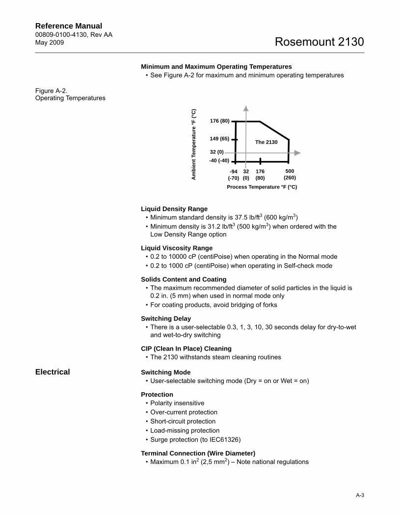
Minimum and Maximum Operating Temperatures• See Figure A-2 for maximum and minimum operating temperatures
Figure A-2. Operating Temperatures
Liquid Density Range• Minimum standard density is 37.5 lb/ft3 (600 kg/m3)• Minimum density is 31.2 lb/ft3 (500 kg/m3) when ordered with the
Low Density Range option
Liquid Viscosity Range• 0.2 to 10000 cP (centiPoise) when operating in the Normal mode• 0.2 to 1000 cP (centiPoise) when operating in Self-check mode
Solids Content and Coating• The maximum recommended diameter of solid particles in the liquid is
0.2 in. (5 mm) when used in normal mode only• For coating products, avoid bridging of forks
Switching Delay• There is a user-selectable 0.3, 1, 3, 10, 30 seconds delay for dry-to-wet
and wet-to-dry switching
CIP (Clean In Place) Cleaning• The 2130 withstands steam cleaning routines
Electrical Switching Mode• User-selectable switching mode (Dry = on or Wet = on)
Protection• Polarity insensitive• Over-current protection• Short-circuit protection• Load-missing protection• Surge protection (to IEC61326)
Terminal Connection (Wire Diameter)• Maximum 0.1 in2 (2,5 mm2) – Note national regulations
176 (80)
176 (80)
-40 (-40)
-94 (-70)
500 (260)
Process Temperature °F (°C)A
mb
ien
t Te
mp
erat
ure
°F
(°C
)
149 (65)
32 (0)
32 (0)
The 2130
Reference Manual00809-0100-4130, Rev AA
May 2009Rosemount 2130
A-4
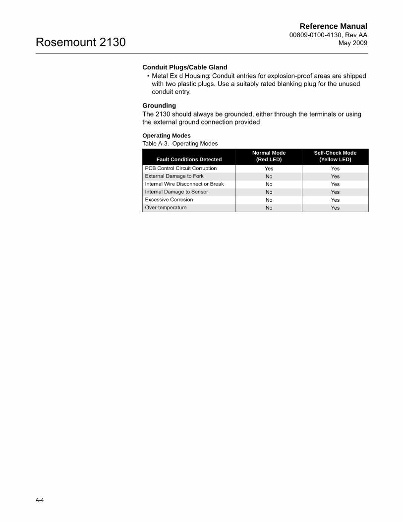
Conduit Plugs/Cable Gland• Metal Ex d Housing: Conduit entries for explosion-proof areas are shipped
with two plastic plugs. Use a suitably rated blanking plug for the unused conduit entry.
GroundingThe 2130 should always be grounded, either through the terminals or using the external ground connection provided
Operating ModesTable A-3. Operating Modes
Fault Conditions DetectedNormal Mode
(Red LED)Self-Check Mode
(Yellow LED)
PCB Control Circuit Corruption Yes YesExternal Damage to Fork No YesInternal Wire Disconnect or Break No YesInternal Damage to Sensor No YesExcessive Corrosion No YesOver-temperature No Yes
Reference Manual 00809-0100-4130, Rev AAMay 2009
A-5
Rosemount 2130
DIMENSIONAL DRAWINGS
2130 Thread Mounting (Standard Length). . . . . . . . . . . . . . . page A-52130 Thread Mounting (Extended Length) . . . . . . . . . . . . . . page A-62130 Flange Mounting (Standard Length) . . . . . . . . . . . . . . . page A-72130 Flange Mounting (Extended Length) . . . . . . . . . . . . . . page A-82130 Hygienic Fitting (Standard Length) . . . . . . . . . . . . . . . . page A-92130 Hygienic Fitting (Extended Length). . . . . . . . . . . . . . . . page A-10
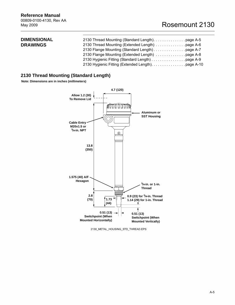
2130 Thread Mounting (Standard Length)
1.575 (40) A/FHexagon
Aluminum or SST Housing
0.51 (13)Switchpoint (When
Mounted Horizontally)
0.51 (13)Switchpoint (When Mounted Vertically)
3/4-in. or 1-in.Thread
13.8(350)
4.7 (120)
0.9 (23) for 3/4-in. Thread1.14 (29) for 1-in. Thread1.73
(44)
Cable EntryM20x1.5 or3/4-in. NPT
Note: Dimensions are in inches (millimeters)
2130_METAL_HOUSING_STD_THREAD.EPS
2.8(70)
Allow 1.2 (30)To Remove Lid
Reference Manual00809-0100-4130, Rev AA
May 2009Rosemount 2130
A-6
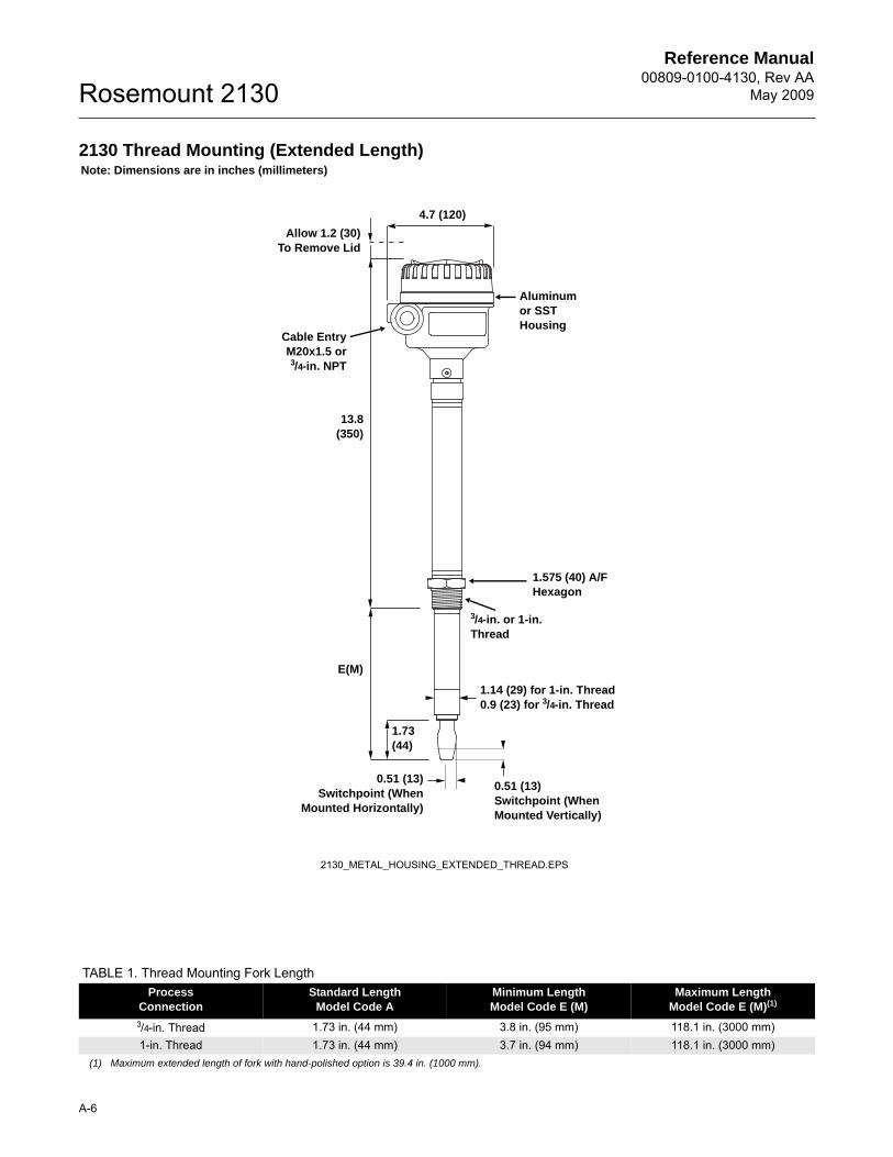
2130 Thread Mounting (Extended Length)
TABLE 1. Thread Mounting Fork LengthProcess
ConnectionStandard Length
Model Code AMinimum LengthModel Code E (M)
Maximum Length Model Code E (M)(1)
(1) Maximum extended length of fork with hand-polished option is 39.4 in. (1000 mm).
3/4-in. Thread 1.73 in. (44 mm) 3.8 in. (95 mm) 118.1 in. (3000 mm)1-in. Thread 1.73 in. (44 mm) 3.7 in. (94 mm) 118.1 in. (3000 mm)
1.575 (40) A/F Hexagon
Aluminumor SSTHousing
3/4-in. or 1-in.Thread
E(M)
1.73(44)
Cable EntryM20x1.5 or3/4-in. NPT
Note: Dimensions are in inches (millimeters)
2130_METAL_HOUSING_EXTENDED_THREAD.EPS
0.51 (13)Switchpoint (When
Mounted Horizontally)
0.51 (13)Switchpoint (When Mounted Vertically)
13.8(350)
4.7 (120)
Allow 1.2 (30)To Remove Lid
1.14 (29) for 1-in. Thread0.9 (23) for 3/4-in. Thread
Reference Manual 00809-0100-4130, Rev AAMay 2009
A-7
Rosemount 2130
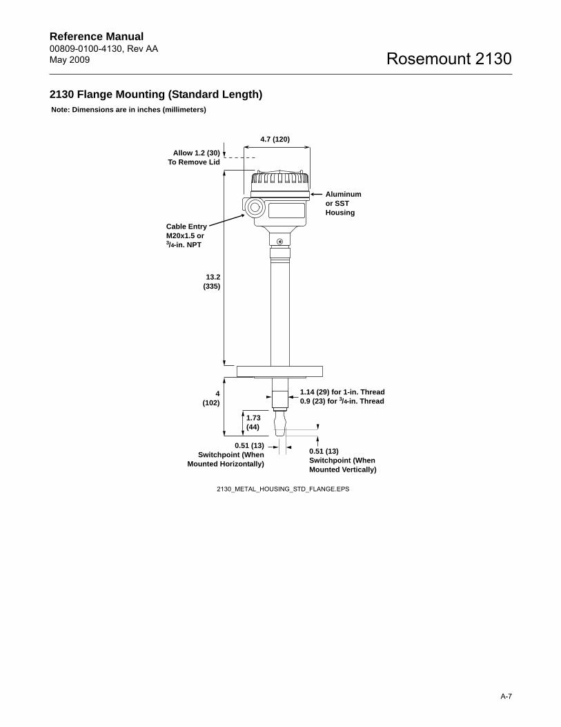
2130 Flange Mounting (Standard Length)Note: Dimensions are in inches (millimeters)
Aluminumor SSTHousing
13.2(335)
Cable EntryM20x1.5 or3/4-in. NPT
1.73(44)
4(102)
2130_METAL_HOUSING_STD_FLANGE.EPS
0.51 (13)Switchpoint (When
Mounted Horizontally)
1.14 (29) for 1-in. Thread0.9 (23) for 3/4-in. Thread
0.51 (13)Switchpoint (When Mounted Vertically)
4.7 (120)
Allow 1.2 (30)To Remove Lid
Reference Manual00809-0100-4130, Rev AA
May 2009Rosemount 2130
A-8
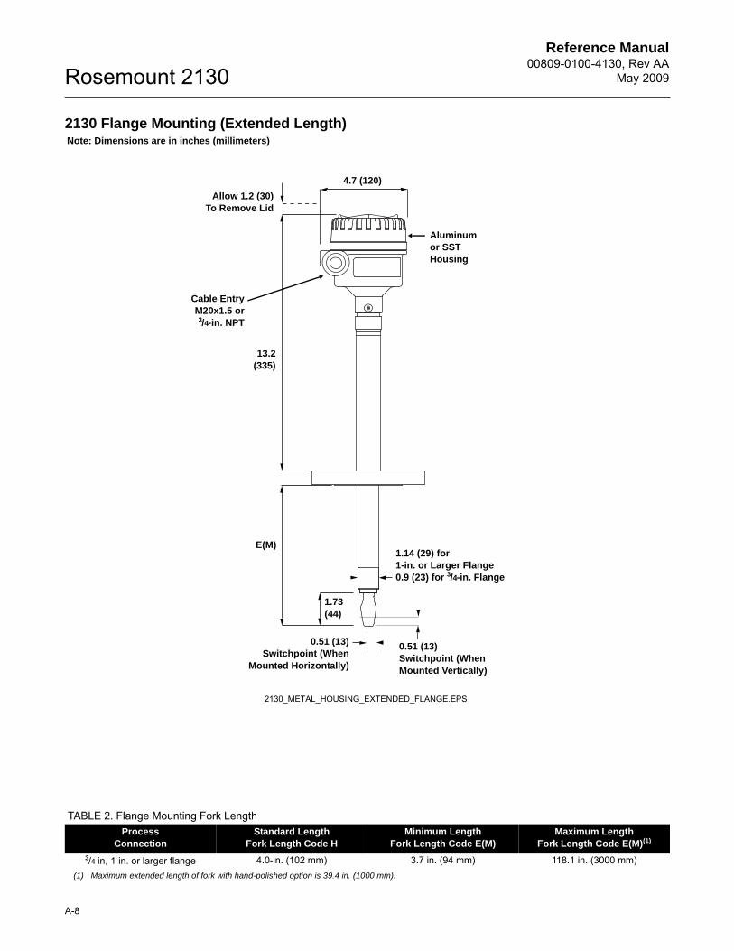
2130 Flange Mounting (Extended Length)
TABLE 2. Flange Mounting Fork LengthProcess
ConnectionStandard Length
Fork Length Code HMinimum Length
Fork Length Code E(M)Maximum Length
Fork Length Code E(M)(1)
(1) Maximum extended length of fork with hand-polished option is 39.4 in. (1000 mm).
3/4 in, 1 in. or larger flange 4.0-in. (102 mm) 3.7 in. (94 mm) 118.1 in. (3000 mm)
Note: Dimensions are in inches (millimeters)
Aluminumor SSTHousing
Cable EntryM20x1.5 or3/4-in. NPT
1.73(44)
13.2(335)
E(M)
2130_METAL_HOUSING_EXTENDED_FLANGE.EPS
0.51 (13)Switchpoint (When
Mounted Horizontally)
1.14 (29) for 1-in. or Larger Flange0.9 (23) for 3/4-in. Flange
0.51 (13)Switchpoint (When Mounted Vertically)
4.7 (120)
Allow 1.2 (30)To Remove Lid
Reference Manual 00809-0100-4130, Rev AAMay 2009
A-9
Rosemount 2130
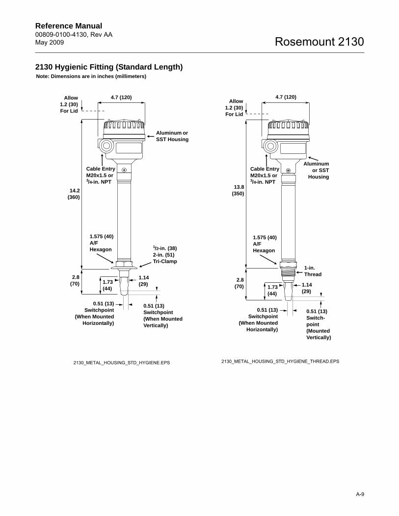
2130 Hygienic Fitting (Standard Length)Note: Dimensions are in inches (millimeters)
Aluminum or SST Housing
Cable EntryM20x1.5 or3/4-in. NPT
1.14(29)1.73
(44)
14.2(360)
2.8(70)
1/2-in. (38)2-in. (51)Tri-Clamp
1.575 (40)A/FHexagon
1-in.Thread
1.14(29)
1.73(44)
1.575 (40)A/FHexagon
Cable EntryM20x1.5 or3/4-in. NPT
Aluminumor SST
Housing
2130_METAL_HOUSING_STD_HYGIENE.EPS
4.7 (120) 4.7 (120)
0.51 (13)Switchpoint
(When MountedHorizontally)
0.51 (13)Switchpoint(When Mounted Vertically)
0.51 (13)Switch-point(Mounted Vertically)
0.51 (13)Switchpoint
(When MountedHorizontally)
2.8(70)
13.8(350)
Allow1.2 (30)For Lid
Allow1.2 (30)For Lid
2130_METAL_HOUSING_STD_HYGIENE_THREAD.EPS
Reference Manual00809-0100-4130, Rev AA
May 2009Rosemount 2130
A-10
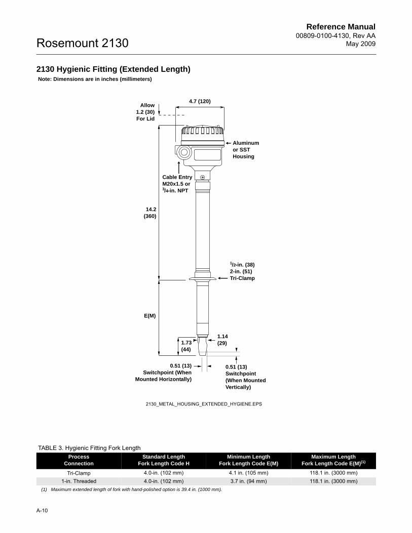
2130 Hygienic Fitting (Extended Length)
TABLE 3. Hygienic Fitting Fork LengthProcess
ConnectionStandard Length
Fork Length Code HMinimum Length
Fork Length Code E(M)Maximum Length
Fork Length Code E(M)(1)
(1) Maximum extended length of fork with hand-polished option is 39.4 in. (1000 mm).
Tri-Clamp 4.0-in. (102 mm) 4.1 in. (105 mm) 118.1 in. (3000 mm)1-in. Threaded 4.0-in. (102 mm) 3.7 in. (94 mm) 118.1 in. (3000 mm)
Note: Dimensions are in inches (millimeters)
1.14(29)1.73
(44)
1/2-in. (38)2-in. (51)Tri-Clamp
Cable EntryM20x1.5 or3/4-in. NPT
Aluminumor SST Housing
E(M)
2130_METAL_HOUSING_EXTENDED_HYGIENE.EPS
0.51 (13)Switchpoint(When Mounted Vertically)
0.51 (13)Switchpoint (When
Mounted Horizontally)
4.7 (120)Allow
1.2 (30)For Lid
14.2(360)
Reference Manual 00809-0100-4130, Rev AAMay 2009
A-11
Rosemount 2130
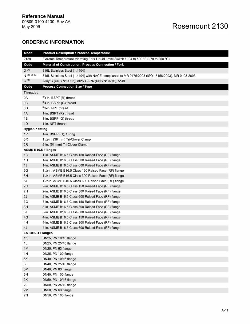
ORDERING INFORMATION
Model Product Description / Process Temperature
2130 Extreme Temperature Vibrating Fork Liquid Level Switch / –94 to 500 °F (–70 to 260 °C)
Code Material of Construction: Process Connection / Fork
D (1) 316L Stainless Steel (1.4404) N (1) (2) (3) 316L Stainless Steel (1.4404) with NACE compliance to MR 0175:2003 (ISO 15156:2003), MR 0103-2003C (4) Alloy C (UNS N10002), Alloy C-276 (UNS N10276), solid
Code Process Connection Size / Type
Threaded
0A 3/4-in. BSPT (R) thread0B 3/4-in. BSPP (G) thread0D 3/4-in. NPT thread1A 1-in. BSPT (R) thread1B 1-in. BSPP (G) thread1D 1-in. NPT threadHygienic fitting
1P 1-in. BSPP (G), O-ring5R 11/2-in. (38 mm) Tri-Clover Clamp2R 2-in. (51 mm) Tri-Clover ClampASME B16.5 Flanges
1G 1-in. ASME B16.5 Class 150 Raised Face (RF) flange1H 1-in. ASME B16.5 Class 300 Raised Face (RF) flange1J 1-in. ASME B16.5 Class 600 Raised Face (RF) flange5G 11/2-in. ASME B16.5 Class 150 Raised Face (RF) flange5H 11/2-in. ASME B16.5 Class 300 Raised Face (RF) flange5J 11/2-in. ASME B16.5 Class 600 Raised Face (RF) flange2G 2-in. ASME B16.5 Class 150 Raised Face (RF) flange2H 2-in. ASME B16.5 Class 300 Raised Face (RF) flange2J 2-in. ASME B16.5 Class 600 Raised Face (RF) flange3G 3-in. ASME B16.5 Class 150 Raised Face (RF) flange3H 3-in. ASME B16.5 Class 300 Raised Face (RF) flange3J 3-in. ASME B16.5 Class 600 Raised Face (RF) flange4G 4-in. ASME B16.5 Class 150 Raised Face (RF) flange4H 4-in. ASME B16.5 Class 300 Raised Face (RF) flange4J 4-in. ASME B16.5 Class 600 Raised Face (RF) flangeEN 1092-1 Flanges
1K DN25, PN 10/16 flange1L DN25, PN 25/40 flange1M DN25, PN 63 flange1N DN25, PN 100 flange5K DN40, PN 10/16 flange5L DN40, PN 25/40 flange5M DN40, PN 63 flange5N DN40, PN 100 flange2K DN50, PN 10/16 flange2L DN50, PN 25/40 flange2M DN50, PN 63 flange2N DN50, PN 100 flange
Reference Manual00809-0100-4130, Rev AA
May 2009Rosemount 2130
A-12
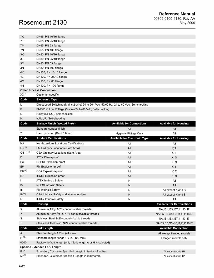
7K DN65, PN 10/16 flange7L DN65, PN 25/40 flange7M DN65, PN 63 flange7N DN65, PN 100 flange3K DN80, PN 10/16 flange3L DN80, PN 25/40 flange3M DN80, PN 63 flange3N DN80, PN 100 flange4K DN100, PN 10/16 flange4L DN100, PN 25/40 flange4M DN100, PN 63 flange4N DN100, PN 100 flangeOther Process Connection
XX (5) Customer specific
Code Electronic Type
L Direct Load Switching (Mains 2-wire) 24 to 264 Vac, 50/60 Hz, 24 to 60 Vdc, Self-checkingP PNP/PLC Low Voltage (3-wire) 24 to 60 Vdc, Self-checkingD Relay (DPCO), Self-checkingN NAMUR, Self-checking
Code Surface Finish (Wetted Parts) Available for Connections Available for Housing
1 Standard surface finish All All2 Hand polished (Ra < 0.8 µm) Hygienic Fittings Only All
Code Product Certifications Available for Electronic Type Available for Housing
NA No Hazardous Locations Certifications All AllG5 (6) FM Ordinary Locations (Safe Area) All Y, TG6 (7) (8) CSA Ordinary Locations (Safe Area) All Y, TE1 ATEX Flameproof All X, SE3 NEPSI Explosion-proof All X, SE5 FM Explosion-proof All Y, TE6 (8) CSA Explosion-proof All Y, TE7 IECEx Explosion-proof All X, SI1 ATEX Intrinsic Safety N AllI3 NEPSI Intrinsic Safety N AllI5 FM Intrinsic Safety N All except X and SI6 (8) CSA Intrinsic Safety and Non-Incendive N All except X and SI7 IECEx Intrinsic Safety N All
Code Housing Available for Certifications
X Aluminum Alloy, M20 conduits/cable threads NA, E1, E3, E7, I1, I3, I7Y Aluminum Alloy, 3/4-in. NPT conduits/cable threads NA,E5,E6,G5,G6,I1,I3,I5,I6,I7S Stainless Steel, M20 conduits/cable threads NA, E1, E3, E7. I1, I3, I7T Stainless Steel 3/4-in. NPT conduits/cable threads NA,E5,E6,G5,G6,I1,I3,I5,I6,I7
Code Fork Length Available Connection
A Standard length 1.7 in. (44 mm) All except flanged modelsH (3) Standard length flange 4.0 in. (102 mm) Flanged models only0000 Factory default length (only if fork length A or H is selected)Specific Extended Fork Length
E (9) Extended, Customer Specified Length in tenths of Inches All except code 1P
M (9) Extended, Customer Specified Length in millimeters All except code 1P
Reference Manual 00809-0100-4130, Rev AAMay 2009
A-13
Rosemount 2130
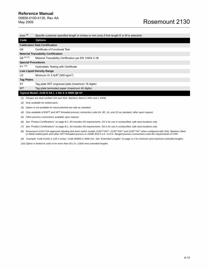
xxxx (9) Specific customer specified length in inches or mm (only if fork length E or M is selected)
Code Options
Calibration Data Certification
Q4 Certificate of Functional TestMaterial Traceability Certification
Q8 (2) (3) Material Traceability Certification per EN 10204 3.1BSpecial Procedures
P1 (10) Hydrostatic Testing with CertificateLow Liquid Density Range
LD Minimum 31.2 lb/ft3 (500 kg/m3)Tag Plates
ST Tag plate SST engraved plate (maximum 16 digits)WT Tag plate laminated paper (maximum 40 digits)
Typical Model: 2130 D 0A L 1 NA A A 0000 Q8 ST
(1) Flanges are dual certified 316 and 316L Stainless Steel (1.4401 and 1.4404).
(2) Only available for wetted parts.
(3) Option is not available for hand polished wet side as standard.
(4) Only available of BSPT and NPT threaded process connection code 0A, 0D, 1A, and 1D as standard, other upon request.
(5) Other process connections available upon request.
(6) See “Product Certifications” on page B-1. E5 includes G5 requirements. G5 is for use in unclassified, safe area locations only.
(7) See “Product Certifications” on page B-1. E6 includes G6 requirements. G6 is for use in unclassified, safe area locations only.
(8) Rosemount 2130 CSA approved vibrating fork level switch models 2130***G6**, 2130***E6** and 2130***I6** when configured with 316L Stainless Steel (1.4404) wetted parts and either NPT threaded process or ASME B16.5 2-in. to 8-in. flanged process connections meet the requirements of CRN.
(9) Example: Code E1181 is 118.1 inches. Code M3000 is 3000 mm. See “Extended Lengths” on page A-1 for minimum and maximum extended lengths.
(10) Option is limited to units of no more than 59.1-in. (1500 mm) extended lengths.
Reference Manual00809-0100-4130, Rev AA
May 2009Rosemount 2130
A-14
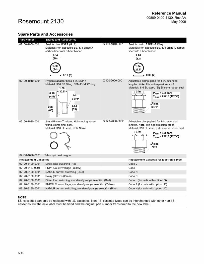
Spare Parts and Accessories
NOTE:I.S. cassettes can only be replaced with I.S. cassettes. Non-I.S. cassette types can be interchanged with other non-I.S. cassettes, but the new label must be fitted and the original part number transferred to the new label.
Part Number Spares and Accessories
02100-1000-0001 Seal for 1-in. BSPP (G1A). Material: Non-asbestos BS7531 grade X carbon fiber with rubber binder
02100-1040-0001 Seal for 3/4-in. BSPP (G3/4A)Material: Non-asbestos BS7531 grade X carbon fiber with rubber binder.
02100-1010-0001 Hygienic adaptor boss 1-in. BSPP. Material: 316 SS fitting. FPM/FKM ‘O’ ring
02120-2000-0001 Adjustable clamp gland for 1-in. extended lengths. Note: It is not explosion-proof.Material: 316 St. steel, (Si) Silicone rubber seal
02100-1020-0001 2-in. (51-mm) Tri-clamp kit including vessel fitting, clamp ring, seal. Material: 316 St. steel, NBR Nitrile
02120-2000-0002 Adjustable clamp gland for 1-in. extended lengths. Note: It is not explosion-proof.Material: 316 St. steel, (Si) Silicone rubber seal
02100-1030-0001 Telescopic test magnet
Replacement Cassettes Replacement Cassette for Electronic Type
02120-3100-0001 Direct load switching (Red) Code L02120-3110-0001 PNP/PLC low voltage (Yellow) Code P02120-3120-0001 NAMUR current switching (Blue) Code N02120-3130-0001 Relay (DPCO) (Green) Code D02120-3160-0001 Direct load switching, low density range selection (Red) Code L (for units with option LD)02120-3170-0001 PNP/PLC low voltage, low density range selection (Yellow) Code P (for units with option LD)02120-3180-0001 NAMUR current switching, low density range selection (Blue) Code N (for units with option LD)
1.54 (39)
1.30 (34)
0.12 (3)
1.26 (32)
1.04 (26.5)
0.08 (2)
1.20 (30.5)
1-in. BSPP
2.36 (60)
0.18 (4.5)
1.54 (39)
1-in.
11/2-in. BSPP
Pmax = 1.3 bargTmax = 257°F (125°C)
1-in.
11/2-in. NPT
Pmax = 1.3 bargTmax = 257°F (125°C)
Reference Manual 00809-0100-4130, Rev AAMay 2009 Rosemount 2130
www.rosemount.com
APPENDIX B PRODUCT CERTIFICATIONS
Safety Messages . . . . . . . . . . . . . . . . . . . . . . . . . . . . . . . . . . . . . . . . . . . page B-1Approved Manufacturing Locations . . . . . . . . . . . . . . . . . . . . . . . . . . . page B-2Ordinary Location Certification for FM . . . . . . . . . . . . . . . . . . . . . . . . . page B-2Ordinary Location Certification for FM . . . . . . . . . . . . . . . . . . . . . . . . . page B-2Ordinary Location Certification for CSA . . . . . . . . . . . . . . . . . . . . . . . . page B-2European Directive Information . . . . . . . . . . . . . . . . . . . . . . . . . . . . . . . page B-2Hazardous Locations Certifications . . . . . . . . . . . . . . . . . . . . . . . . . . . . page B-3
SAFETY MESSAGES Procedures and instructions in this manual may require special precautions to ensure the safety of the personnel performing the operations. Information that raises potential safety issues is indicated by a caution symbol ( ). The external hot surface symbol ( ) is used when a surface is hot and care must be taken to avoid possible burns. If there is a risk of an electrical shock the ( ) symbol is used. Refer to the safety messages listed at the beginning of each section before performing an operation preceded by this symbol.
Failure to follow these installation guidelines could result in death or serious injury.
• The Rosemount 2130 is a liquid level switch. It must be installed, connected, commissioned, operated, and maintained by suitably qualified personnel only, observing any national and local requirements that may apply.
• Ensure the wiring is suitable for the electrical current and the insulation is suitable for the voltage, temperature, and environment.
• Use the equipment only as specified in this manual. Failure to do so may impair the protection provided by the equipment
Explosions could result in death or serious injury
• Verify that the operating environment of the liquid level switch is consistent with the appropriate hazardous area locations
External Surface may be hot.
• Care must be taken to avoid possible burns.
Process leaks could result in death or serious injury.
• Do not remove the liquid level switches while in operation. Removing while in operation may cause process fluid leaks.
Electrical shock could cause death or serious injury.
• If the liquid level switch is installed in a high voltage environment and a fault condition or installation error occurs, high voltage may be present on switch leads and terminals.
• Use extreme caution when making contact with the leads and terminals.
• Make sure that power to the liquid level switch is off while making connections.
Reference Manual00809-0100-4130, Rev AA
May 2009Rosemount 2130
B-2
APPROVED MANUFACTURING LOCATIONS
Slough, UKChanhassen, USASingapore, Singapore.
ORDINARY LOCATION CERTIFICATION FOR FM
G5 Project ID: 3024095The switch has been examined and tested to determine that the design meets basic electrical, mechanical, and fire protection requirements by FM, a nationally recognized testing laboratory (NRTL) as accredited by the Federal Occupational Safety and Health Administration (OSHA).
ORDINARY LOCATION CERTIFICATION FOR CSA
G6 Certificate Number 06 CSA 1878089The switch has been examined and tested to determine that the design meets basic electrical, mechanical, and fire protection requirements by CSA, a nationally recognized testing laboratory as accredited by the Standards Council of Canada (SCC).
CANADIAN REGISTRATION NUMBER
Certificate Number CRN 0F04227.2CRosemount 2130 CSA approved vibrating fork level switch (2130***G6**, 2130***E6**, and 2130***I6**) when configured with 316L Stainless Steel (1.4404) wetted parts and either NPT threaded process or ASME B16.5 2-in. to 8-in. flanged process connections meet the requirements of CRN.
EUROPEAN DIRECTIVE INFORMATION
The EC declaration of conformity for all applicable European directives for this product can be found on the Rosemount website at www.rosemount.com. A hard copy may be obtained by contacting your local sales office.
ATEX Directive (94/9/EC)Complies with the ATEX Directive.
Pressure Equipment Directive (PED) (97/23/EC)The Rosemount 2130 is outside the scope of PED Directive.
L.V. DirectiveEN61010-1 Pollution degree 2, Category II (264V max), Pollution degree 2, Category III (150V max).
Electro Magnetic Compatibility (EMC) DirectiveEN61326 Emissions to Class B. Immunity to industrial location requirements.
CE-markComplies with applicable directives (EMC, ATEX, LVD).
Reference Manual 00809-0100-4130, Rev AAMay 2009
B-3
Rosemount 2130
HAZARDOUS LOCATIONS CERTIFICATIONS
American and Canadian Approvals
Factory Mutual (FM) Explosion-proof Approval
E5 Project ID: 3024095Explosion-proof for Class I, Div. 1, Groups A, B, C, and DTemperature Class:T6 - See Section 10.b overleafEnclosure: Type 4X
Canadian Standards Association (CSA) Explosion-proof Approval
E6 Project ID: 1878089Explosion-proof for Class I, Div. 1, Groups A, B, C, and DTemperature Class:T6 - See Section 10.b overleafEnclosure: Type 4X
Instructions specific to hazardous area installations
1. The equipment may be used with flammable gases and vapors with apparatus Class 1, Div 1, Groups A, B, C and D.
2. FM and CSA Explosion-proof approved versions of the 2130 are certified for use in ambient temperatures of –58°F to 167°F (–50°C to 75°C), and with a maximum process temperature of 500 °F (260 °C).
3. Installation of this equipment shall be carried out by suitably trained personnel, in accordance with the applicable code of practice.
4. Inspection and maintenance of this equipment shall be carried out by suitably trained personnel, in accordance with the applicable code of practice.
5. The user should not repair this equipment.
6. The certification of this equipment relies upon the following materials used in its construction:Body:Aluminum Alloy (ASTM B26 356-T6, LM25 TF, ASTM B85 360.0, orANSI AA360.0), or 316 Stainless Steel
Lid:Aluminum Alloy (ASTM B26 356-T6, LM25 TF, ASTM B85 360.0, orANSI AA360.0), or 316 Stainless Steel
Probe (Switch): 316 Stainless Steel, or Alloy C276 (UNS N10276) or equivalent
Probe (Switch) Filling:Perlite
Lid Seal:Silicone
If the equipment is likely to come into contact with aggressive substances, it is the responsibility of the user to take suitable precautions that prevent it from being adversely affected, thus ensuring that the type of protection is not compromised.
Aggressive Substances – e.g. acidic liquids or gases that may attack metals or solvents that may affect polymeric materials.
Suitable Precautions – e.g. regular checks as part of routine inspections or establishing from the material’s data sheet that it is resistant to specific chemicals.
Reference Manual00809-0100-4130, Rev AA
May 2009Rosemount 2130
B-4
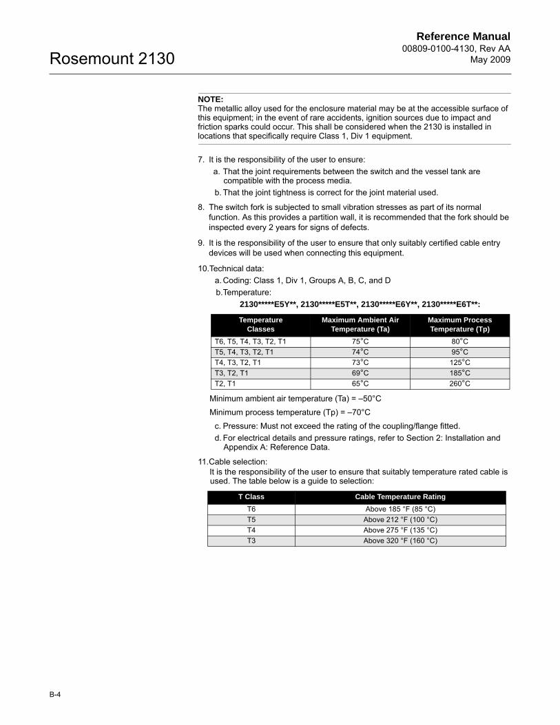
NOTE:The metallic alloy used for the enclosure material may be at the accessible surface of this equipment; in the event of rare accidents, ignition sources due to impact and friction sparks could occur. This shall be considered when the 2130 is installed in locations that specifically require Class 1, Div 1 equipment.
7. It is the responsibility of the user to ensure:a. That the joint requirements between the switch and the vessel tank are
compatible with the process media.b. That the joint tightness is correct for the joint material used.
8. The switch fork is subjected to small vibration stresses as part of its normal function. As this provides a partition wall, it is recommended that the fork should be inspected every 2 years for signs of defects.
9. It is the responsibility of the user to ensure that only suitably certified cable entry devices will be used when connecting this equipment.
10.Technical data:a. Coding: Class 1, Div 1, Groups A, B, C, and Db.Temperature:
2130*****E5Y**, 2130*****E5T**, 2130*****E6Y**, 2130*****E6T**:
Minimum ambient air temperature (Ta) = –50°C
Minimum process temperature (Tp) = –70°C
c. Pressure: Must not exceed the rating of the coupling/flange fitted.d. For electrical details and pressure ratings, refer to Section 2: Installation and
Appendix A: Reference Data.
11.Cable selection:It is the responsibility of the user to ensure that suitably temperature rated cable is used. The table below is a guide to selection:
Temperature Classes
Maximum Ambient Air Temperature (Ta)
Maximum Process Temperature (Tp)
T6, T5, T4, T3, T2, T1 75°C 80°CT5, T4, T3, T2, T1 74°C 95°CT4, T3, T2, T1 73°C 125°CT3, T2, T1 69°C 185°CT2, T1 65°C 260°C
T Class Cable Temperature Rating
T6 Above 185 °F (85 °C)T5 Above 212 °F (100 °C)T4 Above 275 °F (135 °C)T3 Above 320 °F (160 °C)
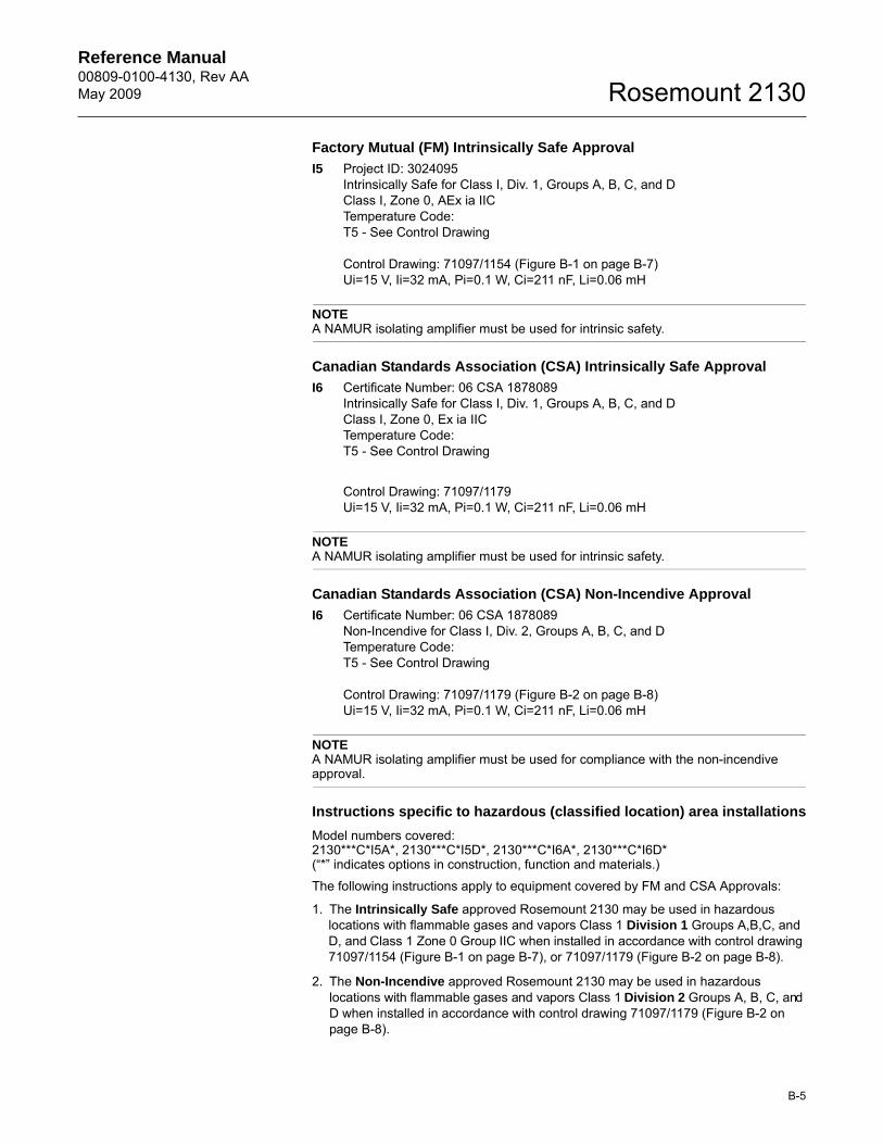
Reference Manual 00809-0100-4130, Rev AAMay 2009
B-5
Rosemount 2130
Factory Mutual (FM) Intrinsically Safe Approval
I5 Project ID: 3024095Intrinsically Safe for Class I, Div. 1, Groups A, B, C, and DClass I, Zone 0, AEx ia IICTemperature Code:T5 - See Control Drawing
Control Drawing: 71097/1154 (Figure B-1 on page B-7)Ui=15 V, Ii=32 mA, Pi=0.1 W, Ci=211 nF, Li=0.06 mH
NOTEA NAMUR isolating amplifier must be used for intrinsic safety.
Canadian Standards Association (CSA) Intrinsically Safe Approval
I6 Certificate Number: 06 CSA 1878089Intrinsically Safe for Class I, Div. 1, Groups A, B, C, and DClass I, Zone 0, Ex ia IICTemperature Code:T5 - See Control Drawing
Control Drawing: 71097/1179 Ui=15 V, Ii=32 mA, Pi=0.1 W, Ci=211 nF, Li=0.06 mH
NOTEA NAMUR isolating amplifier must be used for intrinsic safety.
Canadian Standards Association (CSA) Non-Incendive Approval
I6 Certificate Number: 06 CSA 1878089Non-Incendive for Class I, Div. 2, Groups A, B, C, and DTemperature Code:T5 - See Control Drawing
Control Drawing: 71097/1179 (Figure B-2 on page B-8)Ui=15 V, Ii=32 mA, Pi=0.1 W, Ci=211 nF, Li=0.06 mH
NOTEA NAMUR isolating amplifier must be used for compliance with the non-incendive approval.
Instructions specific to hazardous (classified location) area installations
Model numbers covered:2130***C*I5A*, 2130***C*I5D*, 2130***C*I6A*, 2130***C*I6D*(“*” indicates options in construction, function and materials.)
The following instructions apply to equipment covered by FM and CSA Approvals:
1. The Intrinsically Safe approved Rosemount 2130 may be used in hazardous locations with flammable gases and vapors Class 1 Division 1 Groups A,B,C, and D, and Class 1 Zone 0 Group IIC when installed in accordance with control drawing 71097/1154 (Figure B-1 on page B-7), or 71097/1179 (Figure B-2 on page B-8).
2. The Non-Incendive approved Rosemount 2130 may be used in hazardous locations with flammable gases and vapors Class 1 Division 2 Groups A, B, C, and D when installed in accordance with control drawing 71097/1179 (Figure B-2 on page B-8).
Reference Manual00809-0100-4130, Rev AA
May 2009Rosemount 2130
B-6
3. The apparatus electronics is only certified for use in ambient temperatures in the range of –50ºC to +80ºC. It should not be used outside this range. However, the switch may be located in the process medium which may be at a higher temperature than the electronics but must not be higher than the Temperature Class for the respective process gas/medium.
It is a condition of the Approval that the temperature of the electronics is in the range of –58°F to +176°F (–50ºC to +80ºC). It must not be used outside this range. It will be necessary to limit the external ambient temperature if the process temperature is high. See Control Drawing 71097/1179 (Figure B-2 on page B-8)
4. Suitably trained personnel shall carry out installation in accordance with the applicable code of practice.
5. The user should not repair this equipment.
6. If the equipment is likely to come into contact with aggressive substances, it is the responsibility of the user to take suitable precautions that prevent it from being adversely affected, thus ensuring that the type of protection is not compromised.
Aggressive Substances – e.g. acidic liquids or gases that may attack metals or solvents that may affect polymeric materials.
Suitable Precautions – e.g. regular checks as part of routine inspections or establishing from the material’s data sheet that it is resistant to specific chemicals.
7. If the enclosure is made of an alloy or plastic material, the following precautions must be observed:
a. The metallic alloy used for the enclosure material may be at the accessible surface of this equipment; in the event of rare accidents, ignition sources due to impact and friction sparks could occur.
b. Under certain extreme circumstances, the non-metallic parts incorporated in the enclosure of the Rosemount 2130 may generate an ignition-capable level of electrostatic charge. Therefore, when they are used for applications that specifically require group II equipment, the Rosemount 2130 shall not be installed in a location where the external conditions are conducive to the build-up of electrostatic charge on such surfaces. Additionally, the Rosemount 2130 shall only be cleaned with a damp cloth.
8. Technical Data: I.S. Approval: Class 1 Division 1 Groups A, B, C, and D, Class 1 Zone 0 AEx ia IIC Non-Incendive Approval: Class 1 Division 2 Groups A, B, C, and DSee Control Drawing (Figure B-2 on page B-8.)
Input parameters: Vmax:15V, Imax:32mA, Pi:100mW, Ci:211nF, Li:60µH
Materials: See “Ordering Information” on page A-11.
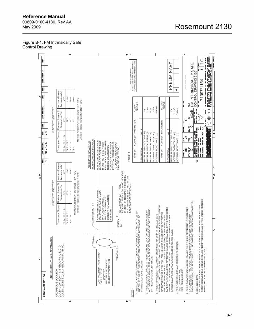
Reference Manual 00809-0100-4130, Rev AAMay 2009
B-7
Rosemount 2130
Figure B-1. FM Intrinsically Safe Control Drawing
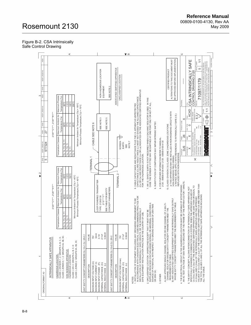
Reference Manual00809-0100-4130, Rev AA
May 2009Rosemount 2130
B-8
Figure B-2. CSA Intrinsically Safe Control Drawing
Reference Manual 00809-0100-4130, Rev AAMay 2009
B-9
Rosemount 2130
European Approvals ATEX Flameproof Approvals
E1 Certificate: Sira 05ATEX1129XFlameproof and Dust:ATEX Marking II 1/2 G DEx d IIC T6-T2, Ex tD A21 (T85°C to 265°C) IP6X
Instructions specific to hazardous area installations(Reference European ATEX Directive 94/9/EC, Annex II, 1.0.6.)
The following instructions apply to the equipment covered by certificate numberSira 05ATEX1129X:
1. The equipment may be used with flammable gases and vapors with apparatus groups IIA, IIB, and IIC, and with temperature classes T1, T2, T3, T4, T5, and T6. The temperature class of the installation will be determined from the higher of the process or ambient temperature.
2. The equipment may be used in a hazardous area with flammable dusts.
3. The equipment has not been assessed as a safety related device (as referred to by Directive 94/9/EC Annex II, clause 1.5).
4. Installation of this equipment shall be carried out by suitably trained personnel, in accordance with the applicable code of practice.
5. Inspection and maintenance of this equipment shall be carried out by suitably trained personnel, in accordance with the applicable code of practice.
6. The user should not repair this equipment.
7. The certification of this equipment relies upon the following materials used in its construction:Body:Aluminum Alloy (ASTM B26 356-T6, LM25 TF, ASTM B85 360.0, ANSI AA360.0), or Stainless Steel 316L type
Lid:Aluminum Alloy (ASTM B26 356-T6, LM25 TF, ASTM B85 360.0, ANSI AA360.0), or Stainless Steel 316L type
Probe (Switch):Stainless Steel 316 Type, or Alloy C276 (UNS N10276) or equivalent
Probe (Switch) Filling:Perlite
Lid Seal:Silicone
8. If the equipment is likely to come into contact with aggressive substances, it is the responsibility of the user to take suitable precautions that prevent it from being adversely affected, thus ensuring that the type of protection is not compromised.Aggressive substances: e.g. acidic liquids or gases that may attack metals, or solvents that may affect polymeric materials
Suitable precautions: e.g. regular checks as part of routine inspections or establishing from the material’s data sheet that it is resistant to specific chemicals
9. It is the responsibility of the user to ensure: a. That the joint requirements between the probe (switch) and the vessel tank are
compatible with the process media.b. That the joint tightness is correct for the joint material used.c. That only suitably certified cable entry devices will be utilized when connecting
this equipment.d. That any unused cable entries are sealed with suitably certified stopping plugs.
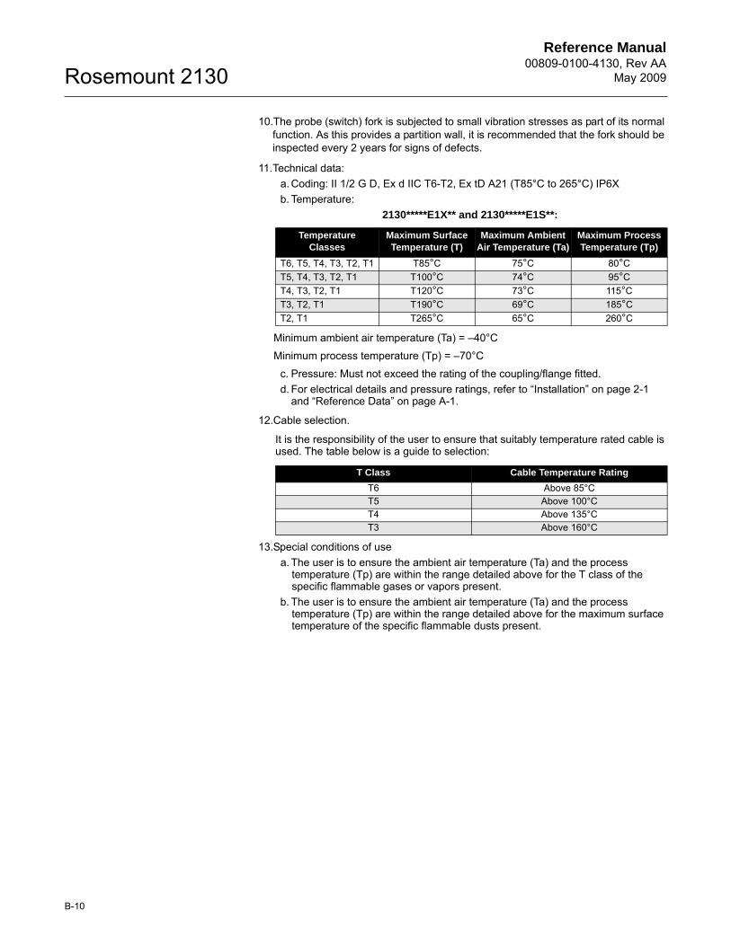
Reference Manual00809-0100-4130, Rev AA
May 2009Rosemount 2130
B-10
10.The probe (switch) fork is subjected to small vibration stresses as part of its normal function. As this provides a partition wall, it is recommended that the fork should be inspected every 2 years for signs of defects.
11.Technical data:a. Coding: II 1/2 G D, Ex d IIC T6-T2, Ex tD A21 (T85°C to 265°C) IP6Xb. Temperature:
2130*****E1X** and 2130*****E1S**:
Minimum ambient air temperature (Ta) = –40°C
Minimum process temperature (Tp) = –70°C
c. Pressure: Must not exceed the rating of the coupling/flange fitted.d. For electrical details and pressure ratings, refer to “Installation” on page 2-1
and “Reference Data” on page A-1.
12.Cable selection.
It is the responsibility of the user to ensure that suitably temperature rated cable is used. The table below is a guide to selection:
13.Special conditions of usea. The user is to ensure the ambient air temperature (Ta) and the process
temperature (Tp) are within the range detailed above for the T class of the specific flammable gases or vapors present.
b. The user is to ensure the ambient air temperature (Ta) and the process temperature (Tp) are within the range detailed above for the maximum surface temperature of the specific flammable dusts present.
Temperature Classes
Maximum Surface Temperature (T)
Maximum Ambient Air Temperature (Ta)
Maximum Process Temperature (Tp)
T6, T5, T4, T3, T2, T1 T85°C 75°C 80°CT5, T4, T3, T2, T1 T100°C 74°C 95°CT4, T3, T2, T1 T120°C 73°C 115°CT3, T2, T1 T190°C 69°C 185°CT2, T1 T265°C 65°C 260°C
T Class Cable Temperature Rating
T6 Above 85°CT5 Above 100°CT4 Above 135°CT3 Above 160°C
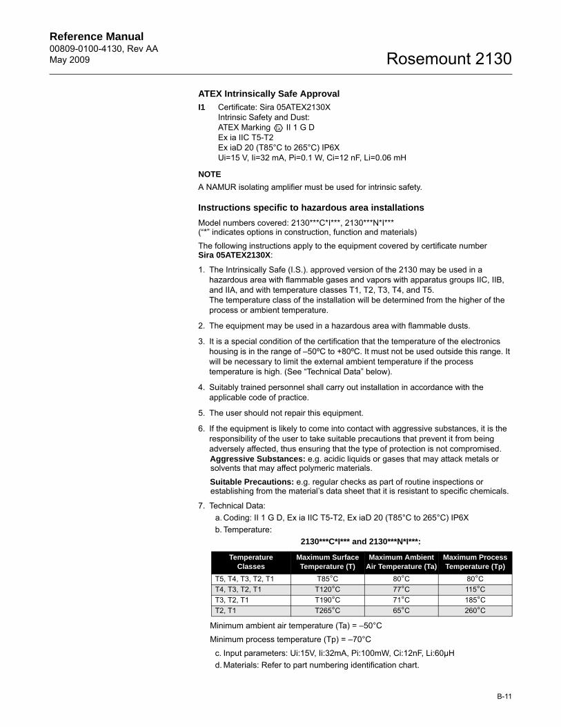
Reference Manual 00809-0100-4130, Rev AAMay 2009
B-11
Rosemount 2130
ATEX Intrinsically Safe Approval
I1 Certificate: Sira 05ATEX2130XIntrinsic Safety and Dust:ATEX Marking II 1 G DEx ia IIC T5-T2 Ex iaD 20 (T85°C to 265°C) IP6XUi=15 V, Ii=32 mA, Pi=0.1 W, Ci=12 nF, Li=0.06 mH
NOTE
A NAMUR isolating amplifier must be used for intrinsic safety.
Instructions specific to hazardous area installations
Model numbers covered: 2130***C*I***, 2130***N*I***(“*” indicates options in construction, function and materials)
The following instructions apply to the equipment covered by certificate numberSira 05ATEX2130X:
1. The Intrinsically Safe (I.S.). approved version of the 2130 may be used in a hazardous area with flammable gases and vapors with apparatus groups IIC, IIB, and IIA, and with temperature classes T1, T2, T3, T4, and T5. The temperature class of the installation will be determined from the higher of the process or ambient temperature.
2. The equipment may be used in a hazardous area with flammable dusts.
3. It is a special condition of the certification that the temperature of the electronics housing is in the range of –50ºC to +80ºC. It must not be used outside this range. It will be necessary to limit the external ambient temperature if the process temperature is high. (See “Technical Data” below).
4. Suitably trained personnel shall carry out installation in accordance with the applicable code of practice.
5. The user should not repair this equipment.
6. If the equipment is likely to come into contact with aggressive substances, it is the responsibility of the user to take suitable precautions that prevent it from being adversely affected, thus ensuring that the type of protection is not compromised.Aggressive Substances: e.g. acidic liquids or gases that may attack metals or solvents that may affect polymeric materials.
Suitable Precautions: e.g. regular checks as part of routine inspections or establishing from the material’s data sheet that it is resistant to specific chemicals.
7. Technical Data:a. Coding: II 1 G D, Ex ia IIC T5-T2, Ex iaD 20 (T85°C to 265°C) IP6Xb. Temperature:
2130***C*I*** and 2130***N*I***:
Minimum ambient air temperature (Ta) = –50°C
Minimum process temperature (Tp) = –70°C
c. Input parameters: Ui:15V, Ii:32mA, Pi:100mW, Ci:12nF, Li:60µHd. Materials: Refer to part numbering identification chart.
Temperature Classes
Maximum Surface Temperature (T)
Maximum Ambient Air Temperature (Ta)
Maximum Process Temperature (Tp)
T5, T4, T3, T2, T1 T85°C 80°C 80°CT4, T3, T2, T1 T120°C 77°C 115°CT3, T2, T1 T190°C 71°C 185°CT2, T1 T265°C 65°C 260°C
Reference Manual00809-0100-4130, Rev AA
May 2009Rosemount 2130
B-12
8. Special conditions of use:a. If the enclosure is made of an alloy or plastic material, the following precautions
must be observed:i. The metallic alloy used for the enclosure material may be at the accessible
surface of this equipment; in the event of rare accidents, ignition sources due to impact and friction sparks could occur. This shall be considered when the 2130 is being installed in locations that specifically require group II, category 1G equipment.
ii. Under certain extreme circumstances, the non-metallic parts incorporated in the enclosure of the 2130 may generate an ignition-capable level of electrostatic charge. Therefore, when they are used for applications that specifically require group II, category 1 equipment, the 2130 shall not be installed in a location where the external conditions are conducive to the build-up of electrostatic charge on such surfaces. Additionally, the 2130 shall only be cleaned with a damp cloth.
b. The user is to ensure the ambient air temperature (Ta) and the process temperature (Tp) are within the range detailed above for the T class of the specific flammable gases or vapors present.
c. The user is to ensure the ambient air temperature (Ta) and the process temperature (Tp) are within the range detailed above for the maximum surface temperature of the specific flammable dusts present.
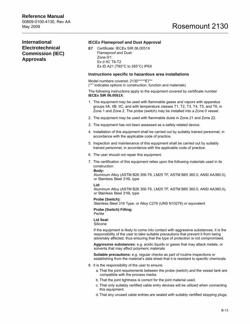
Reference Manual 00809-0100-4130, Rev AAMay 2009
B-13
Rosemount 2130
International Electrotechnical Commission (IEC) Approvals
IECEx Flameproof and Dust Approval
E7 Certificate: IECEx SIR 06.0051XFlameproof and Dust:Zone 0/1Ex d IIC T6-T2Ex tD A21 (T85°C to 265°C) IP6X
Instructions specific to hazardous area installations
Model numbers covered: 2130*****E7**(“*” indicates options in construction, function and materials)
The following instructions apply to the equipment covered by certificate numberIECEx SIR 06.0051X:
1. The equipment may be used with flammable gases and vapors with apparatus groups IIA, IIB, IIC, and with temperature classes T1, T2, T3, T4, T5, and T6, in Zone 1 and Zone 2. The probe (switch) may be installed into a Zone 0 vessel.
2. The equipment may be used with flammable dusts in Zone 21 and Zone 22.
3. The equipment has not been assessed as a safety related device.
4. Installation of this equipment shall be carried out by suitably trained personnel, in accordance with the applicable code of practice.
5. Inspection and maintenance of this equipment shall be carried out by suitably trained personnel, in accordance with the applicable code of practice.
6. The user should not repair this equipment.
7. The certification of this equipment relies upon the following materials used in its construction:Body:Aluminum Alloy (ASTM B26 356-T6, LM25 TF, ASTM B85 360.0, ANSI AA360.0), or Stainless Steel 316L type
Lid:Aluminum Alloy (ASTM B26 356-T6, LM25 TF, ASTM B85 360.0, ANSI AA360.0), or Stainless Steel 316L type
Probe (Switch):Stainless Steel 316 Type, or Alloy C276 (UNS N10276) or equivalent
Probe (Switch) Filling:Perlite
Lid Seal:Silicone
If the equipment is likely to come into contact with aggressive substances, it is the responsibility of the user to take suitable precautions that prevent it from being adversely affected, thus ensuring that the type of protection is not compromised.
Aggressive substances: e.g. acidic liquids or gases that may attack metals, or solvents that may affect polymeric materials
Suitable precautions: e.g. regular checks as part of routine inspections or establishing from the material’s data sheet that it is resistant to specific chemicals
8. It is the responsibility of the user to ensure: a. That the joint requirements between the probe (switch) and the vessel tank are
compatible with the process media.b. That the joint tightness is correct for the joint material used.c. That only suitably certified cable entry devices will be utilized when connecting
this equipment.d. That any unused cable entries are sealed with suitably certified stopping plugs.

Reference Manual00809-0100-4130, Rev AA
May 2009Rosemount 2130
B-14
9. The probe (switch) fork is subjected to small vibration stresses as part of its normal function. As this provides a partition wall, it is recommended that the fork should be inspected every 2 years for signs of defects.
10.Technical data:a. Coding: Zone 0/1, Ex d IIC T6-T2, Ex tD A21 (T85°C to 265°C) IP6Xb. Temperature:
2130*****E7X** and 2130*****E7S**:
Minimum ambient air temperature (Ta) = –40°C
Minimum process temperature (Tp) = –70°C
c. Pressure: Must not exceed the rating of the coupling/flange fitted.d. For electrical details and pressure ratings, refer to “Installation” on page 2-1
and “Reference Data” on page A-1.
11.Cable selection.
It is the responsibility of the user to ensure that suitably temperature rated cable is used. The table below is a guide to selection:
12.Special conditions of usea. The user is to ensure the ambient air temperature (Ta) and the process
temperature (Tp) are within the range detailed above for the T class of the specific flammable gases or vapors present.
b. The user is to ensure the ambient air temperature (Ta) and the process temperature (Tp) are within the range detailed above for the maximum surface temperature of the specific flammable dusts present.
Temperature Classes
Maximum Surface Temperature (T)
Maximum Ambient Air Temperature (Ta)
Maximum Process Temperature (Tp)
T6, T5, T4, T3, T2, T1 T85°C 75°C 80°CT5, T4, T3, T2, T1 T100°C 74°C 95°CT4, T3, T2, T1 T120°C 73°C 115°CT3, T2, T1 T190°C 69°C 185°CT2, T1 T265°C 65°C 260°C
T Class Cable Temperature Rating
T6 Above 85°CT5 Above 100°CT4 Above 135°CT3 Above 160°C
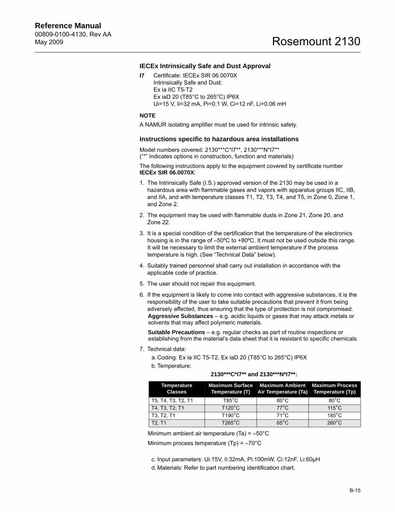
Reference Manual 00809-0100-4130, Rev AAMay 2009
B-15
Rosemount 2130
IECEx Intrinsically Safe and Dust Approval
I7 Certificate: IECEx SIR 06.0070XIntrinsically Safe and Dust:Ex ia IIC T5-T2Ex iaD 20 (T85°C to 265°C) IP6XUi=15 V, Ii=32 mA, Pi=0.1 W, Ci=12 nF, Li=0.06 mH
NOTE
A NAMUR isolating amplifier must be used for intrinsic safety.
Instructions specific to hazardous area installations
Model numbers covered: 2130***C*I7**, 2130***N*I7**(“*” indicates options in construction, function and materials)
The following instructions apply to the equipment covered by certificate numberIECEx SIR 06.0070X:
1. The Intrinsically Safe (I.S.) approved version of the 2130 may be used in a hazardous area with flammable gases and vapors with apparatus groups IIC, IIB, and IIA, and with temperature classes T1, T2, T3, T4, and T5, in Zone 0, Zone 1, and Zone 2.
2. The equipment may be used with flammable dusts in Zone 21, Zone 20, and Zone 22.
3. It is a special condition of the certification that the temperature of the electronics housing is in the range of –50ºC to +80ºC. It must not be used outside this range.It will be necessary to limit the external ambient temperature if the process temperature is high. (See “Technical Data” below).
4. Suitably trained personnel shall carry out installation in accordance with the applicable code of practice.
5. The user should not repair this equipment.
6. If the equipment is likely to come into contact with aggressive substances, it is the responsibility of the user to take suitable precautions that prevent it from being adversely affected, thus ensuring that the type of protection is not compromised.Aggressive Substances – e.g. acidic liquids or gases that may attack metals or solvents that may affect polymeric materials.
Suitable Precautions – e.g. regular checks as part of routine inspections or establishing from the material’s data sheet that it is resistant to specific chemicals.
7. Technical data:a. Coding: Ex ia IIC T5-T2, Ex iaD 20 (T85°C to 265°C) IP6Xb. Temperature:
2130***C*I7** and 2130***N*I7**:
Minimum ambient air temperature (Ta) = –50°C
Minimum process temperature (Tp) = –70°C
c. Input parameters: Ui:15V, Ii:32mA, Pi:100mW, Ci:12nF, Li:60µHd. Materials: Refer to part numbering identification chart.
Temperature Classes
Maximum Surface Temperature (T)
Maximum Ambient Air Temperature (Ta)
Maximum Process Temperature (Tp)
T5, T4, T3, T2, T1 T85°C 80°C 80°CT4, T3, T2, T1 T120°C 77°C 115°CT3, T2, T1 T190°C 71°C 185°CT2, T1 T265°C 65°C 260°C
Reference Manual00809-0100-4130, Rev AA
May 2009Rosemount 2130
B-16
8. Special conditions of use:a. If the enclosure is made of an alloy or plastic material, the following precautions
must be observed:i. The metallic alloy used for the enclosure material may be at the accessible
surface of this equipment; in the event of rare accidents, ignition sources due to impact and friction sparks could occur. This shall be considered when the 2130 is being installed in Zone 0 and Zone 20 locations.
ii. Under certain extreme circumstances, the non-metallic parts incorporated in the enclosure of the 2130 may generate an ignition-capable level of electrostatic charge. Therefore, when they are used in Zone 0 and Zone 20 locations, the 2130 shall not be installed in a location where the external conditions are conducive to the build-up of electrostatic charge on such surfaces. Additionally, the 2130 shall only be cleaned with a damp cloth.
b. The user is to ensure the ambient air temperature (Ta) and the process temperature (Tp) are within the range detailed above for the T class of the specific flammable gases or vapors present.
c. The user is to ensure the ambient air temperature (Ta) and the process temperature (Tp) are within the range detailed above for the maximum surface temperature of the specific flammable dusts present.
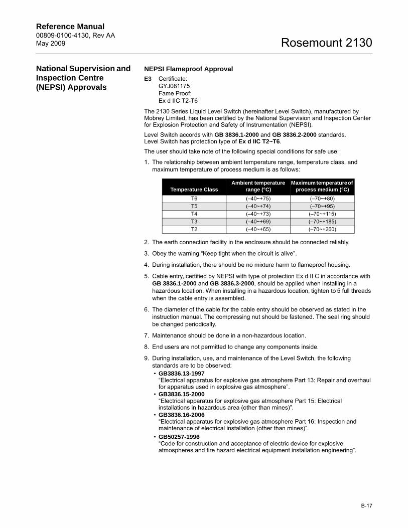
Reference Manual 00809-0100-4130, Rev AAMay 2009
B-17
Rosemount 2130
National Supervision and Inspection Centre (NEPSI) Approvals
NEPSI Flameproof Approval
E3 Certificate: GYJ081175Fame Proof:Ex d IIC T2-T6
The 2130 Series Liquid Level Switch (hereinafter Level Switch), manufactured by Mobrey Limited, has been certified by the National Supervision and Inspection Center for Explosion Protection and Safety of Instrumentation (NEPSI).
Level Switch accords with GB 3836.1-2000 and GB 3836.2-2000 standards.Level Switch has protection type of Ex d IIC T2~T6.
The user should take note of the following special conditions for safe use:
1. The relationship between ambient temperature range, temperature class, and maximum temperature of process medium is as follows:
2. The earth connection facility in the enclosure should be connected reliably.
3. Obey the warning “Keep tight when the circuit is alive”.
4. During installation, there should be no mixture harm to flameproof housing.
5. Cable entry, certified by NEPSI with type of protection Ex d II C in accordance with GB 3836.1-2000 and GB 3836.3-2000, should be applied when installing in a hazardous location. When installing in a hazardous location, tighten to 5 full threads when the cable entry is assembled.
6. The diameter of the cable for the cable entry should be observed as stated in the instruction manual. The compressing nut should be fastened. The seal ring should be changed periodically.
7. Maintenance should be done in a non-hazardous location.
8. End users are not permitted to change any components inside.
9. During installation, use, and maintenance of the Level Switch, the following standards are to be observed:• GB3836.13-1997
“Electrical apparatus for explosive gas atmosphere Part 13: Repair and overhaul for apparatus used in explosive gas atmosphere”.
• GB3836.15-2000“Electrical apparatus for explosive gas atmosphere Part 15: Electrical installations in hazardous area (other than mines)”.
• GB3836.16-2006“Electrical apparatus for explosive gas atmosphere Part 16: Inspection and maintenance of electrical installation (other than mines)”.
• GB50257-1996“Code for construction and acceptance of electric device for explosive atmospheres and fire hazard electrical equipment installation engineering”.
Temperature ClassAmbient temperature
range (°C)Maximum temperature of
process medium (°C)
T6 (–40~+75) (–70~+80)T5 (–40~+74) (–70~+95)T4 (–40~+73) (–70~+115)T3 (–40~+69) (–70~+185)T2 (–40~+65) (–70~+260)
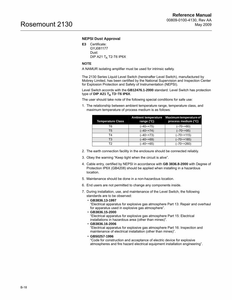
Reference Manual00809-0100-4130, Rev AA
May 2009Rosemount 2130
B-18
NEPSI Dust Approval
E3 Certificate: GYJ081177Dust:DIP A21 TA T2-T6 IP6X
NOTE
A NAMUR isolating amplifier must be used for intrinsic safety.
The 2130 Series Liquid Level Switch (hereinafter Level Switch), manufactured by Mobrey Limited, has been certified by the National Supervision and Inspection Center for Explosion Protection and Safety of Instrumentation (NEPSI).
Level Switch accords with the GB12476.1-2000 standard. Level Switch has protection type of DIP A21 TA T3~T6 IP6X.
The user should take note of the following special conditions for safe use:
1. The relationship between ambient temperature range, temperature class, and maximum temperature of process medium is as follows:
2. The earth connection facility in the enclosure should be connected reliably.
3. Obey the warning “Keep tight when the circuit is alive”.
4. Cable entry, certified by NEPSI in accordance with GB 3836.8-2000 with Degree of Protection IP6X (GB4208) should be applied when installing in a hazardous location.
5. Maintenance should be done in a non-hazardous location.
6. End users are not permitted to change any components inside.
7. During installation, use, and maintenance of the Level Switch, the following standards are to be observed:• GB3836.13-1997
“Electrical apparatus for explosive gas atmosphere Part 13: Repair and overhaul for apparatus used in explosive gas atmosphere”.
• GB3836.15-2000“Electrical apparatus for explosive gas atmosphere Part 15: Electrical installations in hazardous area (other than mines)”.
• GB3836.16-2006“Electrical apparatus for explosive gas atmosphere Part 16: Inspection and maintenance of electrical installation (other than mines)”.
• GB50257-1996“Code for construction and acceptance of electric device for explosive atmospheres and fire hazard electrical equipment installation engineering”.
Temperature ClassAmbient temperature
range (°C)Maximum temperature of
process medium (°C)
T6 (–40~+75) (–70~+80)T5 (–40~+74) (–70~+95)T4 (–40~+73) (–70~+115)T3 (–40~+69) (–70~+185)T2 (–40~+65) (–70~+260)
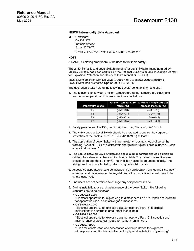
Reference Manual 00809-0100-4130, Rev AAMay 2009
B-19
Rosemount 2130
NEPSI Intrinsically Safe Approval
I3 Certificate: GYJ081176Intrinsic Safety:Ex ia IIC T2-T5Ui=15 V, Ii=32 mA, Pi=0.1 W, Ci=12 nF, Li=0.06 mH
NOTE
A NAMUR isolating amplifier must be used for intrinsic safety.
The 2130 Series Liquid Level Switch (hereinafter Level Switch), manufactured by Mobrey Limited, has been certified by the National Supervision and Inspection Center for Explosion Protection and Safety of Instrumentation (NEPSI).
Level Switch accords with GB 3836.1-2000 and GB 3836.4-2000 standards.Level Switch has protection type of Ex ia IIC T2~T5.
The user should take note of the following special conditions for safe use:
1. The relationship between ambient temperature range, temperature class, and maximum temperature of process medium is as follows:
2. Safety parameters: Ui=15 V, Ii=32 mA, Pi=0.1 W, Ci=12 nF, Li=0.06 mH
3. The cable entry of Level Switch should be protected to ensure the degree of protection of the enclosure to IP 20 (GB4208-1993) at least.
4. The application of Level Switch with non-metallic housing should observe the warning: “Caution- Risk of electrostatic charge build-up on plastic surfaces. Clean only with damp cloth”.
5. The cables between Level Switch and associated apparatus should be shielded cables (the cables must have an insulated shield). The cable core section area should be greater than 0.5 mm2. The shielded has to be grounded reliably. The wiring has to not be affected by electromagnetic disturbance.
6. Associated apparatus should be installed in a safe location, and during installation, operation and maintenance, the regulations of the instruction manual have to be strictly observed.
7. End users are not permitted to change any components inside.
8. During installation, use and maintenance of the Level Switch, the following standards are to be observed:• GB3836.13-1997
“Electrical apparatus for explosive gas atmosphere Part 13: Repair and overhaul for apparatus used in explosive gas atmosphere”.
• GB3836.15-2000“Electrical apparatus for explosive gas atmosphere Part 15: Electrical installations in hazardous area (other than mines)”.
• GB3836.16-2006“Electrical apparatus for explosive gas atmosphere Part 16: Inspection and maintenance of electrical installation (other than mines)”.
• GB50257-1996“Code for construction and acceptance of electric device for explosive atmospheres and fire hazard electrical equipment installation engineering”.
Temperature ClassAmbient temperature
range (°C)Maximum temperature of
process medium (°C)
T5 (–50~+80) (–70~+80)T4 (–50~+77) (–70~+115)T3 (–50~+71) (–70~+185)T2 (–50~+65) (–70~+260)
Reference Manual00809-0100-4130, Rev AA
May 2009Rosemount 2130
B-20


Reference Manual00809-0100-4130, Rev AA
May 2009Rosemount 2130
© 2009 Rosemount, Inc.
Emerson Process Management Rosemount Inc.8200 Market BoulevardChanhassen, MN 55317 USAT (U.S.) 1-800-999-9307T (International) (952) 906-8888F (952) 949-7001www.rosemount.com
Emerson Process ManagementBleigistrasse 23P.O. Box 1046CH 6341 BaarSwitzerlandT +41 (0) 41 768 6111F +41 (0) 41 768 6300
Emerson Process ManagementAsia Pacific Pte Ltd1 Pandan CrescentSingapore 128461T +65 6777 8211F +65 6777 0947Service Support Hotline: +65 6770 8711Email: [email protected]
Emerson FZEP.O. Box 17033Jebel Ali Free ZoneDubai UAET +971 4 883 5235F +971 4 883 5312
00809-0100-4130 Rev AA 05/09
The Emerson logo is a trademark and service mark of Emerson Electric Co.Rosemount and the Rosemount logotype are registered trademarks of Rosemount Inc.PlantWeb is a registered trademark of one of the Emerson Process Management group of companies.HART is a registered trademark of the HART Communication Foundation.DeltaV is a registered trademark of Emerson Process Management group of companies.All other marks are the property of their respective owners.
Standard Terms and Conditions of Sale can be found at www.rosemount.com\terms_of_sale