Embed Size (px)
Citation preview
Reference Manual00809-0100-4029, Rev CA
March 2018
Rosemount™ 2110 Level SwitchVibrating Fork

i
Reference Manual 00809-0100-4029, Rev CA
Title PageMarch 2018
Title Page
Rosemount™ 2110 Level Switch
Vibrating Fork
Read this manual before working with the product. For personal and system safety, and for optimum product performance, make sure you thoroughly understand the contents before installing, using, or maintaining this product.
For technical assistance, contacts are listed below:
Customer Central
Technical support, quoting, and order-related questions.
United States - 1-800-999-9307 (7:00 am to 7:00 pm CST)
Asia Pacific- 65 777 8211
Europe/ Middle East/ Africa - 49 (8153) 9390
North American Response Center
Equipment service needs.
1-800-654-7768 (24 hours—includes Canada)
Outside of these areas, contact your local Emerson™ representative.
The products described in this document are NOT designed for nuclear-qualified applications. Using non-nuclear qualified products in applications that require nuclear-qualified hardware or products may cause inaccurate readings.
For information on Rosemount nuclear-qualified products, contact your local Emerson Sales Representative.

ii
Reference Manual00809-0100-4029, Rev CA
Title PageMarch 2018
Title Page
Reference Manual 00809-0100-4029, Rev CA
ContentsMarch 2018
Contents
1Section 1: Introduction1.1 Safety messages . . . . . . . . . . . . . . . . . . . . . . . . . . . . . . . . . . . . . . . . . . . . . . . . . . . . . . . . . . . . . . . . . . . 1
1.2 Manual overview . . . . . . . . . . . . . . . . . . . . . . . . . . . . . . . . . . . . . . . . . . . . . . . . . . . . . . . . . . . . . . . . . . . 2
1.3 Introduction to the Rosemount™ 2110. . . . . . . . . . . . . . . . . . . . . . . . . . . . . . . . . . . . . . . . . . . . . . . . 2
1.3.1 Features list. . . . . . . . . . . . . . . . . . . . . . . . . . . . . . . . . . . . . . . . . . . . . . . . . . . . . . . . . . . . . . . . . . 2
1.3.2 Measurement principle . . . . . . . . . . . . . . . . . . . . . . . . . . . . . . . . . . . . . . . . . . . . . . . . . . . . . . . 3
1.3.3 Short fork technology. . . . . . . . . . . . . . . . . . . . . . . . . . . . . . . . . . . . . . . . . . . . . . . . . . . . . . . . . 3
1.3.4 Special features . . . . . . . . . . . . . . . . . . . . . . . . . . . . . . . . . . . . . . . . . . . . . . . . . . . . . . . . . . . . . . 4
1.4 Product recycling and disposal . . . . . . . . . . . . . . . . . . . . . . . . . . . . . . . . . . . . . . . . . . . . . . . . . . . . . . . 5
2Section 2: Installation2.1 Safety messages . . . . . . . . . . . . . . . . . . . . . . . . . . . . . . . . . . . . . . . . . . . . . . . . . . . . . . . . . . . . . . . . . . . 7
2.2 Considerations before installation. . . . . . . . . . . . . . . . . . . . . . . . . . . . . . . . . . . . . . . . . . . . . . . . . . . . 8
2.2.1 Environmental considerations . . . . . . . . . . . . . . . . . . . . . . . . . . . . . . . . . . . . . . . . . . . . . . . . . 8
2.2.2 Application considerations . . . . . . . . . . . . . . . . . . . . . . . . . . . . . . . . . . . . . . . . . . . . . . . . . . . . 8
2.2.3 Installation considerations. . . . . . . . . . . . . . . . . . . . . . . . . . . . . . . . . . . . . . . . . . . . . . . . . . . .10
2.3 Installation procedures . . . . . . . . . . . . . . . . . . . . . . . . . . . . . . . . . . . . . . . . . . . . . . . . . . . . . . . . . . . .13
2.3.1 Process connection seals . . . . . . . . . . . . . . . . . . . . . . . . . . . . . . . . . . . . . . . . . . . . . . . . . . . . .13
2.3.2 Correct fork alignment . . . . . . . . . . . . . . . . . . . . . . . . . . . . . . . . . . . . . . . . . . . . . . . . . . . . . . .14
2.3.3 Mounting the threaded versions . . . . . . . . . . . . . . . . . . . . . . . . . . . . . . . . . . . . . . . . . . . . . .15
2.3.4 Mounting the Tri Clamp versions . . . . . . . . . . . . . . . . . . . . . . . . . . . . . . . . . . . . . . . . . . . . . .17
2.4 Electrical installation . . . . . . . . . . . . . . . . . . . . . . . . . . . . . . . . . . . . . . . . . . . . . . . . . . . . . . . . . . . . . .18
2.4.1 Prepare the electrical connections . . . . . . . . . . . . . . . . . . . . . . . . . . . . . . . . . . . . . . . . . . . . .18
2.4.2 Wiring . . . . . . . . . . . . . . . . . . . . . . . . . . . . . . . . . . . . . . . . . . . . . . . . . . . . . . . . . . . . . . . . . . . . .21
2.5 LED Indication . . . . . . . . . . . . . . . . . . . . . . . . . . . . . . . . . . . . . . . . . . . . . . . . . . . . . . . . . . . . . . . . . . . .24
3Section 3: Troubleshooting3.1 Magnetic test point . . . . . . . . . . . . . . . . . . . . . . . . . . . . . . . . . . . . . . . . . . . . . . . . . . . . . . . . . . . . . . .25
3.2 Inspection. . . . . . . . . . . . . . . . . . . . . . . . . . . . . . . . . . . . . . . . . . . . . . . . . . . . . . . . . . . . . . . . . . . . . . . .25
3.3 Maintenance . . . . . . . . . . . . . . . . . . . . . . . . . . . . . . . . . . . . . . . . . . . . . . . . . . . . . . . . . . . . . . . . . . . . .26
3.4 Troubleshooting . . . . . . . . . . . . . . . . . . . . . . . . . . . . . . . . . . . . . . . . . . . . . . . . . . . . . . . . . . . . . . . . . .26
3.5 Spare parts . . . . . . . . . . . . . . . . . . . . . . . . . . . . . . . . . . . . . . . . . . . . . . . . . . . . . . . . . . . . . . . . . . . . . . .26
3.6 Service support . . . . . . . . . . . . . . . . . . . . . . . . . . . . . . . . . . . . . . . . . . . . . . . . . . . . . . . . . . . . . . . . . . .27
iiiContents

Reference Manual00809-0100-4029, Rev CA
ContentsMarch 2018
AAppendix A: Reference DataA.1 Product Certifications . . . . . . . . . . . . . . . . . . . . . . . . . . . . . . . . . . . . . . . . . . . . . . . . . . . . . . . . . . . . . 29
A.2 Ordering Information, Specifications, and Drawings . . . . . . . . . . . . . . . . . . . . . . . . . . . . . . . . . . 29
iv Contents
Reference Manual 00809-0100-4029, Rev CA
IntroductionMarch 2018
Section 1 Introduction
1.1 Safety messagesProcedures and instructions in this manual may require special precautions to ensure the safety of the personnel performing the operations. Information that raises potential safety issues is indicated by a caution symbol ( ). The external hot surface symbol ( ) is used when a surface is hot and care must be taken to avoid possible burns. If there is a risk of an electrical shock, the ( ) symbol is used. Refer to the safety messages listed at the beginning of each section before performing an operation preceded by this symbol.
Failure to follow these installation guidelines could result in death or serious injury.
Protection afforded by compliance to EN61010-1 may be impaired if the equipment is not used as specified.
The Rosemount™ 2110 must be installed, connected, commissioned, operated, and maintained by suitably qualified personnel only, observing any national and local requirements that may apply.
Ensure the wiring is suitable for the electrical current and the insulation is suitable for the voltage, temperature, and environment.
Use the equipment only as specified in this manual. Failure to do so may impair the protection provided by the equipment.
Any substitution of non-recognized parts may jeopardize safety and is under no circumstances allowed.
Review the product approvals for any restrictions associated with an installation.See “Reference Data” on page 29 for where to find the latest information.
Verify that the operating environment of the level switch is not a hazardous area location.External surface may be hot.
Care must be taken to avoid possible burns.Process leaks could result in death or serious injury.
Install and tighten process connectors before applying pressure. Do not attempt to loosen or remove process connectors while the Rosemount 2110 is in
service.Electrical shock could cause death or serious injury.
If the liquid level switch is installed in a high voltage environment and a fault condition or installation error occurs, high voltage may be present on leads and terminals.
Use extreme caution when making contact with the leads and terminals. Make sure that power to the Rosemount 2110 is off while making connections.
1Introduction
Reference Manual00809-0100-4029, Rev CA
IntroductionMarch 2018
1.2 Manual overviewThis manual provides information on installing, operating, and maintaining all versions of the Rosemount 2110 Vibrating Fork Liquid Level Switch (“level switch”).
Section 2: Installation provides instruction on mechanical and electrical installation procedures.
Section 3: Troubleshooting contains instructions about using the magnetic test point, as well as inspection, basic maintenance, and troubleshooting information.
Appendix A: Reference Data contains instructions on how to find the latest product certifications, specifications, dimension drawings, and ordering information on the Emerson.com/Rosemount site.
NoteRefer to the Rosemount 2110 Quick Start Guide for instruction on hygienic installation of a level switch with a 51 mm Tri Clamp fitting.
1.3 Introduction to the Rosemount 2110The Rosemount 2110 is a liquid point level switch based on the vibrating short fork technology.It is a compact switch with a rugged stainless steel body and forks for use in a wide range of liquid applications. For most liquids, including coating and aerated liquids and slurries, the function is virtually unaffected by flow, turbulence, bubbles, foam, vibration, or changing liquid properties.
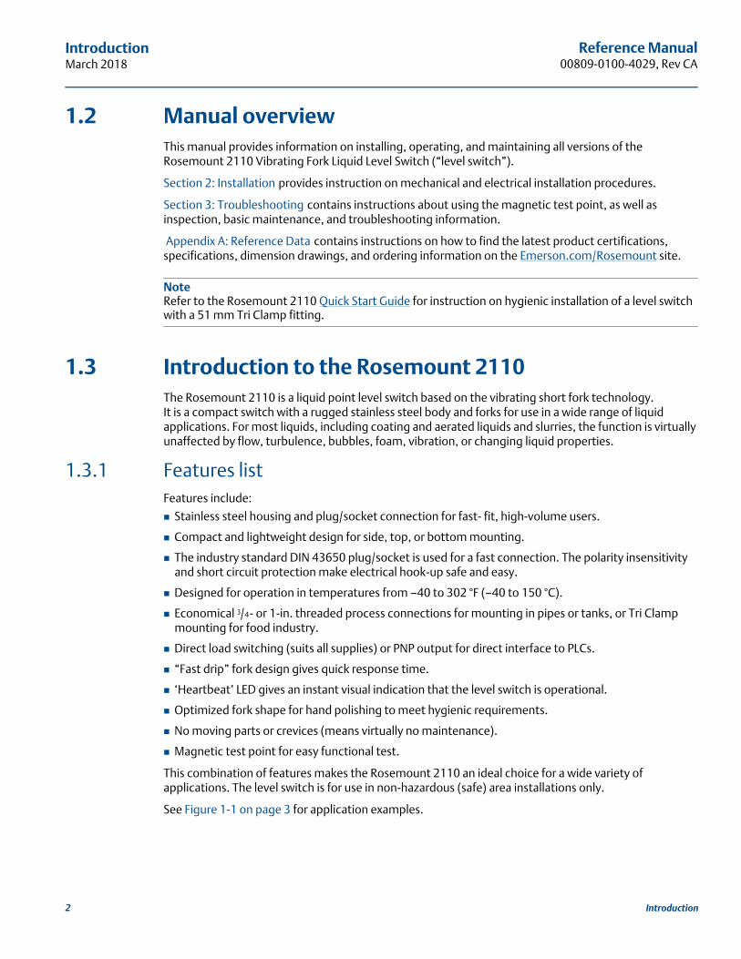
1.3.1 Features listFeatures include:
Stainless steel housing and plug/socket connection for fast- fit, high-volume users.
Compact and lightweight design for side, top, or bottom mounting.
The industry standard DIN 43650 plug/socket is used for a fast connection. The polarity insensitivity and short circuit protection make electrical hook-up safe and easy.
Designed for operation in temperatures from –40 to 302 °F (–40 to 150 °C).
Economical 3/4 - or 1-in. threaded process connections for mounting in pipes or tanks, or Tri Clamp mounting for food industry.
Direct load switching (suits all supplies) or PNP output for direct interface to PLCs.
“Fast drip” fork design gives quick response time.
‘Heartbeat’ LED gives an instant visual indication that the level switch is operational.
Optimized fork shape for hand polishing to meet hygienic requirements.
No moving parts or crevices (means virtually no maintenance).
Magnetic test point for easy functional test.
This combination of features makes the Rosemount 2110 an ideal choice for a wide variety of applications. The level switch is for use in non-hazardous (safe) area installations only.
See Figure 1-1 on page 3 for application examples.
2 Introduction
Reference Manual 00809-0100-4029, Rev CA
IntroductionMarch 2018
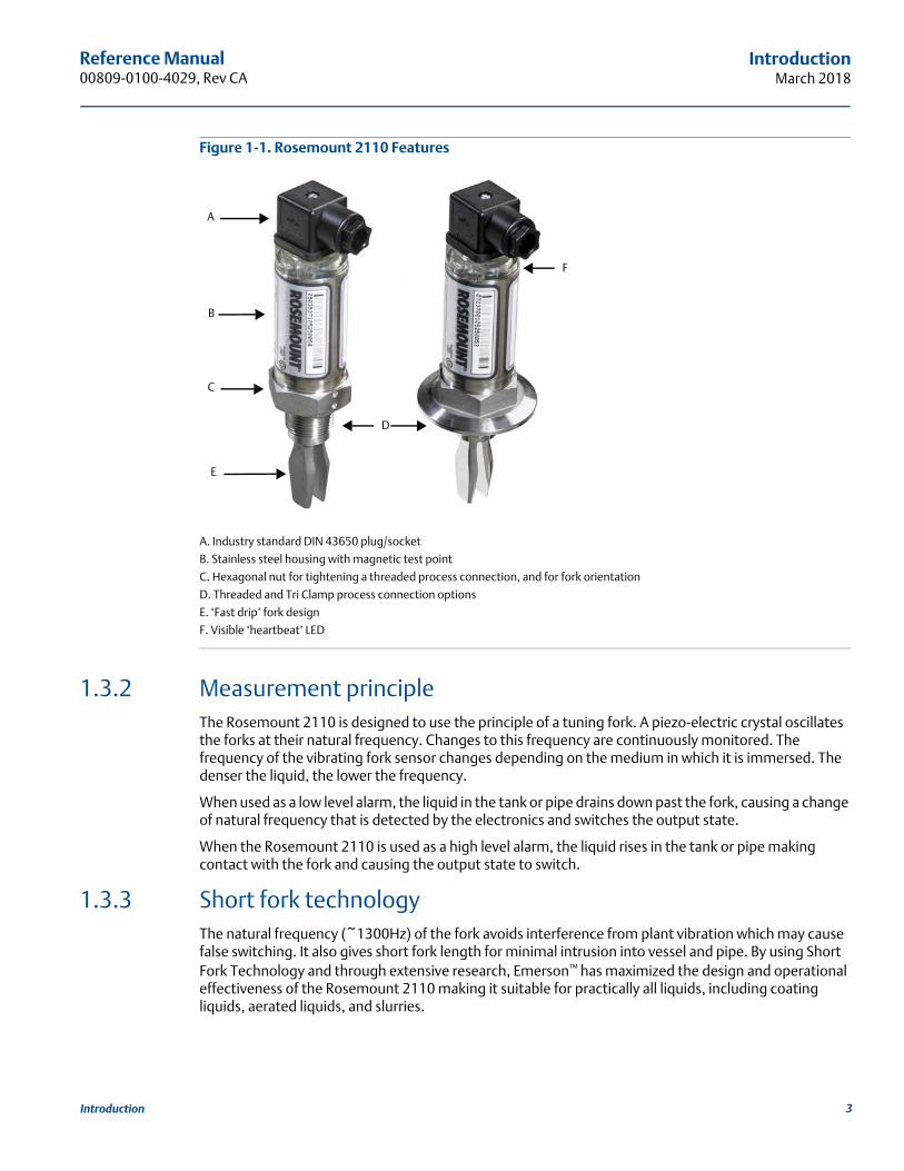
Figure 1-1. Rosemount 2110 Features
A. Industry standard DIN 43650 plug/socket
B. Stainless steel housing with magnetic test point
C. Hexagonal nut for tightening a threaded process connection, and for fork orientation
D. Threaded and Tri Clamp process connection options
E. ‘Fast drip’ fork design
F. Visible ‘heartbeat’ LED
1.3.2 Measurement principleThe Rosemount 2110 is designed to use the principle of a tuning fork. A piezo-electric crystal oscillates the forks at their natural frequency. Changes to this frequency are continuously monitored. The frequency of the vibrating fork sensor changes depending on the medium in which it is immersed. The denser the liquid, the lower the frequency.
When used as a low level alarm, the liquid in the tank or pipe drains down past the fork, causing a change of natural frequency that is detected by the electronics and switches the output state.
When the Rosemount 2110 is used as a high level alarm, the liquid rises in the tank or pipe making contact with the fork and causing the output state to switch.
1.3.3 Short fork technologyThe natural frequency (~1300Hz) of the fork avoids interference from plant vibration which may cause false switching. It also gives short fork length for minimal intrusion into vessel and pipe. By using Short Fork Technology and through extensive research, Emerson™ has maximized the design and operational effectiveness of the Rosemount 2110 making it suitable for practically all liquids, including coating liquids, aerated liquids, and slurries.
A
B
C
D
E
F
3Introduction
Reference Manual00809-0100-4029, Rev CA
IntroductionMarch 2018
1.3.4 Special features
Fork designThe “fast drip” fork design draws liquid away from the fork tips when mounted horizontally, and together with a short switching delay, allows the Rosemount 2110 to react quickly and with greater sensitivity to density variations.
Heartbeat LEDThe Rosemount 2110 has a ‘heartbeat’ LED indicating it is operating, and can be seen at all times.The LED flashes when the switch output is ‘off’ and is constantly lit when 'on'.
Magnetic test pointA magnetic test-point is located on the side of the housing, allowing the user to perform a functional test of the Rosemount 2110 and the system connected to it. Holding a magnet to the test-point causes the output to change state.
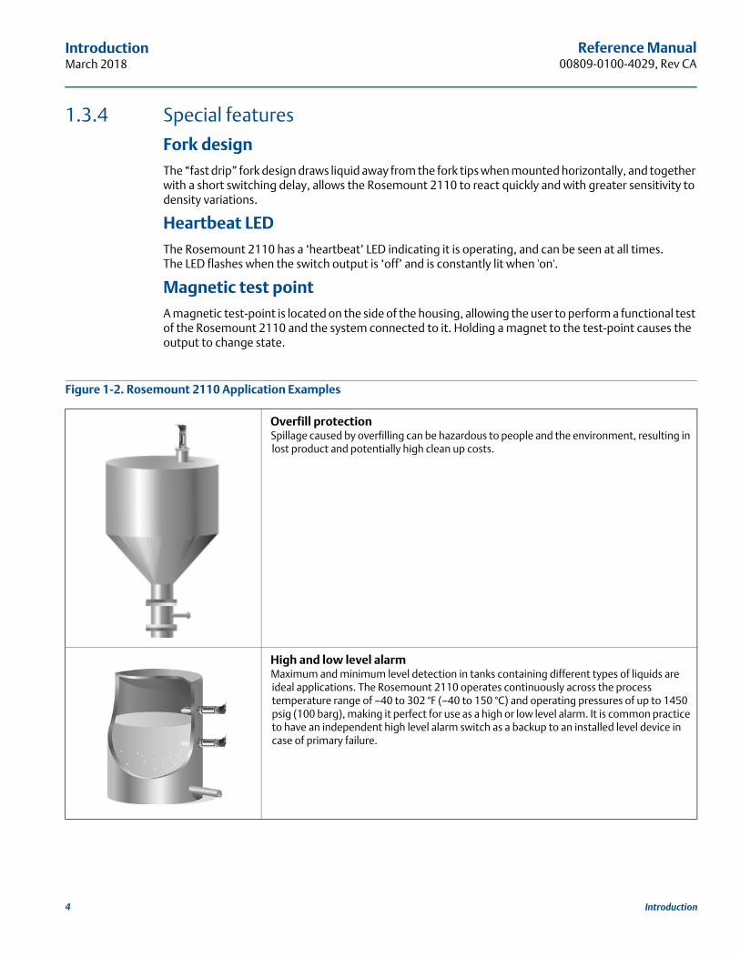
Figure 1-2. Rosemount 2110 Application Examples
Overfill protectionSpillage caused by overfilling can be hazardous to people and the environment, resulting in lost product and potentially high clean up costs.
High and low level alarmMaximum and minimum level detection in tanks containing different types of liquids are ideal applications. The Rosemount 2110 operates continuously across the process temperature range of –40 to 302 °F (–40 to 150 °C) and operating pressures of up to 1450 psig (100 barg), making it perfect for use as a high or low level alarm. It is common practice to have an independent high level alarm switch as a backup to an installed level device in case of primary failure.
4 Introduction
Reference Manual 00809-0100-4029, Rev CA
IntroductionMarch 2018
1.4 Product recycling and disposalRecycling of equipment and packaging should be taken into consideration. The product and packaging should be disposed of in accordance with local and national legislation.
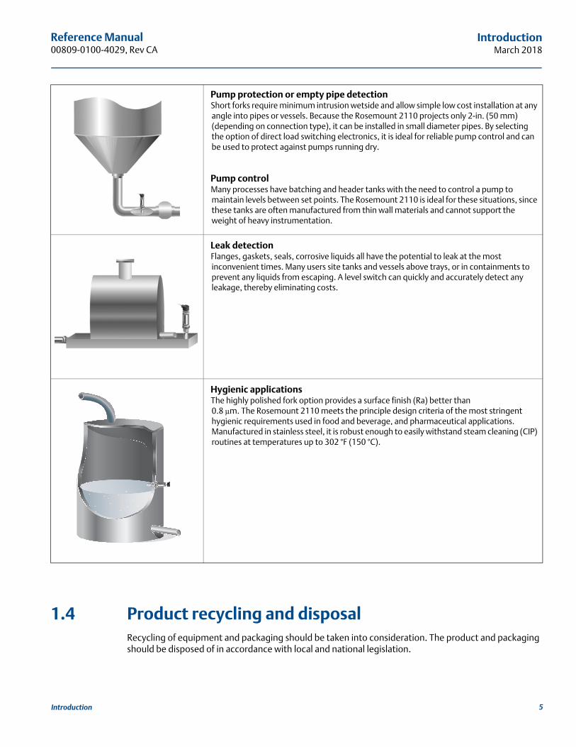
Pump protection or empty pipe detectionShort forks require minimum intrusion wetside and allow simple low cost installation at any angle into pipes or vessels. Because the Rosemount 2110 projects only 2-in. (50 mm) (depending on connection type), it can be installed in small diameter pipes. By selecting the option of direct load switching electronics, it is ideal for reliable pump control and can be used to protect against pumps running dry.
Pump control Many processes have batching and header tanks with the need to control a pump to maintain levels between set points. The Rosemount 2110 is ideal for these situations, since these tanks are often manufactured from thin wall materials and cannot support the weight of heavy instrumentation.
Leak detectionFlanges, gaskets, seals, corrosive liquids all have the potential to leak at the most inconvenient times. Many users site tanks and vessels above trays, or in containments to prevent any liquids from escaping. A level switch can quickly and accurately detect any leakage, thereby eliminating costs.
Hygienic applicationsThe highly polished fork option provides a surface finish (Ra) better than 0.8 μm. The Rosemount 2110 meets the principle design criteria of the most stringent hygienic requirements used in food and beverage, and pharmaceutical applications. Manufactured in stainless steel, it is robust enough to easily withstand steam cleaning (CIP) routines at temperatures up to 302 °F (150 °C).
5Introduction

Reference Manual00809-0100-4029, Rev CA
IntroductionMarch 2018
6 Introduction
Reference Manual 00809-0100-4029, Rev CA
ConfigurationMarch 2018
7Configuration
Section 2 Installation
Safety messages . . . . . . . . . . . . . . . . . . . . . . . . . . . . . . . . . . . . . . . . . . . . . . . . . . . . . . . . . . . . . . . . . . page 7Considerations before installation . . . . . . . . . . . . . . . . . . . . . . . . . . . . . . . . . . . . . . . . . . . . . . . . . . page 8Installation procedures . . . . . . . . . . . . . . . . . . . . . . . . . . . . . . . . . . . . . . . . . . . . . . . . . . . . . . . . . . . . page 13Electrical installation . . . . . . . . . . . . . . . . . . . . . . . . . . . . . . . . . . . . . . . . . . . . . . . . . . . . . . . . . . . . . . page 18LED Indication . . . . . . . . . . . . . . . . . . . . . . . . . . . . . . . . . . . . . . . . . . . . . . . . . . . . . . . . . . . . . . . . . . . . page 24
2.1 Safety messages
Failure to follow these installation guidelines could result in death or serious injury.
The Rosemount™ 2110 Level Switch (“level switch”) must be installed, connected, commissioned, operated, and maintained by suitably qualified personnel only, observing any national and local requirements that may apply.
Ensure the wiring is suitable for the electrical current and the insulation is suitable for the voltage, temperature, and environment.
Use the equipment only as specified in this manual. Failure to do so may impair the protection provided by the equipment.
Any substitution of non-recognized parts may jeopardize safety and is under no circumstances allowed.
Verify that the operating environment of the level switch is not a hazardous area location.
Failure to comply with the following requirements will result in the invalidation of the product safety certification.
Check for risk of process medium build-up on the level switch forks. Avoid situations where drying and coating products may create an excessive build-up (see Figure 2-2 on page 9) or implement preventative maintenance programs to ensure the build-up is not enough to impair performance.
Ensure there is no risk of 'bridging' of the level switch forks. Examples of products that create 'bridging' of the forks are dense paper slurries and bitumen.
External surface may be hot.
Care must be taken to avoid possible burns.
Process leaks may cause harm or result in death.
Install and tighten process connectors before applying pressure.
Do not attempt to loosen or remove process connectors while the level switch is in service.
Electrical shock could cause death or serious injury.
If the level switch is installed in a high voltage environment and a fault condition or installation error occurs, high voltage may be present on leads and terminals.
Use extreme caution when making contact with the leads and terminals.
Make sure that power to the level switch is off while making connections.
Reference Manual00809-0100-4029, Rev CA
ConfigurationMarch 2018
2.2 Considerations before installation
ImportantEmerson™ is not in a position to evaluate or guarantee the compatibility of the process fluid or other process parameters with the product, options, configuration or materials of construction selected.
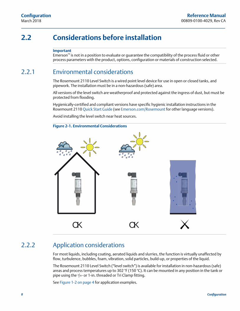
2.2.1 Environmental considerationsThe Rosemount 2110 Level Switch is a wired point level device for use in open or closed tanks, and pipework. The installation must be in a non-hazardous (safe) area.
All versions of the level switch are weatherproof and protected against the ingress of dust, but must be protected from flooding.
Hygienically-certified and compliant versions have specific hygienic installation instructions in the Rosemount 2110 Quick Start Guide (see Emerson.com/Rosemount for other language versions).
Avoid installing the level switch near heat sources.
Figure 2-1. Environmental Considerations
2.2.2 Application considerationsFor most liquids, including coating, aerated liquids and slurries, the function is virtually unaffected by flow, turbulence, bubbles, foam, vibration, solid particles, build-up, or properties of the liquid.
The Rosemount 2110 Level Switch (“level switch”) is available for installation in non-hazardous (safe) areas and process temperatures up to 302 °F (150 °C). It can be mounted in any position in the tank or pipe using the 3/4 - or 1-in. threaded or Tri Clamp fitting.
See Figure 1-2 on page 4 for application examples.
OKOK
8 Configuration
Reference Manual 00809-0100-4029, Rev CA
ConfigurationMarch 2018
Application limits
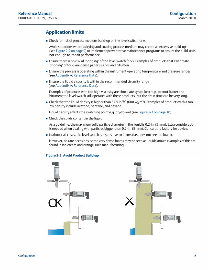
Check for risk of process medium build-up on the level switch forks.
Avoid situations where a drying and coating process medium may create an excessive build-up (see Figure 2-2 on page 9) or implement preventative maintenance programs to ensure the build-up is not enough to impair performance.
Ensure there is no risk of ‘bridging’ of the level switch forks. Examples of products that can create ‘bridging’ of forks are dense paper slurries and bitumen.
Ensure the process is operating within the instrument operating temperature and pressure ranges(see Appendix A: Reference Data).
Ensure the liquid viscosity is within the recommended viscosity range(see Appendix A: Reference Data).
Examples of products with too high viscosity are chocolate syrup, ketchup, peanut butter and bitumen; the level switch still operates with these products, but the drain time can be very long.
Check that the liquid density is higher than 37.5 lb/ft3 (600 kg/m3). Examples of products with a too low density include acetone, pentane, and hexane.
Liquid density affects the switching point e.g. dry-to-wet (see Figure 2-3 on page 10).
Check the solids content in the liquid.
As a guideline, the maximum solid particle diameter in the liquid is 0.2-in. (5 mm). Extra consideration is needed when dealing with particles bigger than 0.2-in. (5 mm). Consult the factory for advice.
In almost all cases, the level switch is insensitive to foams (i.e. does not see the foam).
However, on rare occasions, some very dense foams may be seen as liquid; known examples of this are found in ice-cream and orange juice manufacturing.
Figure 2-2. Avoid Product Build-up
OK
9Configuration
Reference Manual00809-0100-4029, Rev CA
ConfigurationMarch 2018
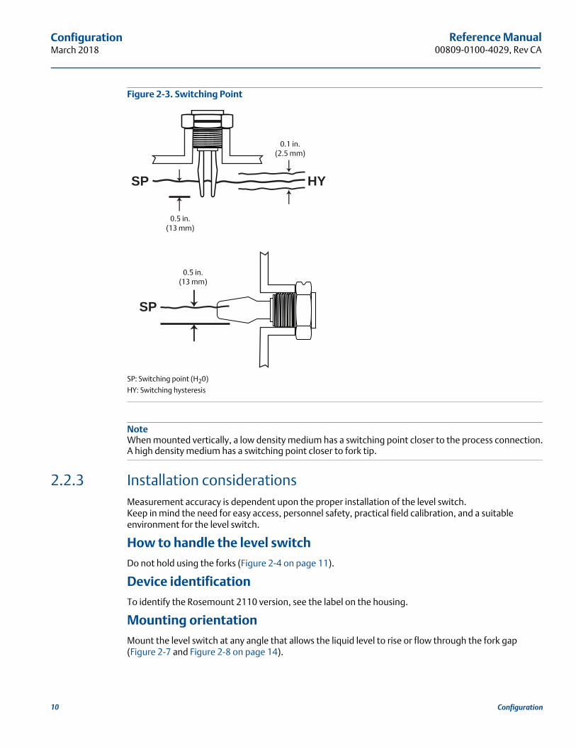
Figure 2-3. Switching Point
SP: Switching point (H20)
HY: Switching hysteresis
NoteWhen mounted vertically, a low density medium has a switching point closer to the process connection.A high density medium has a switching point closer to fork tip.
2.2.3 Installation considerationsMeasurement accuracy is dependent upon the proper installation of the level switch.Keep in mind the need for easy access, personnel safety, practical field calibration, and a suitable environment for the level switch.
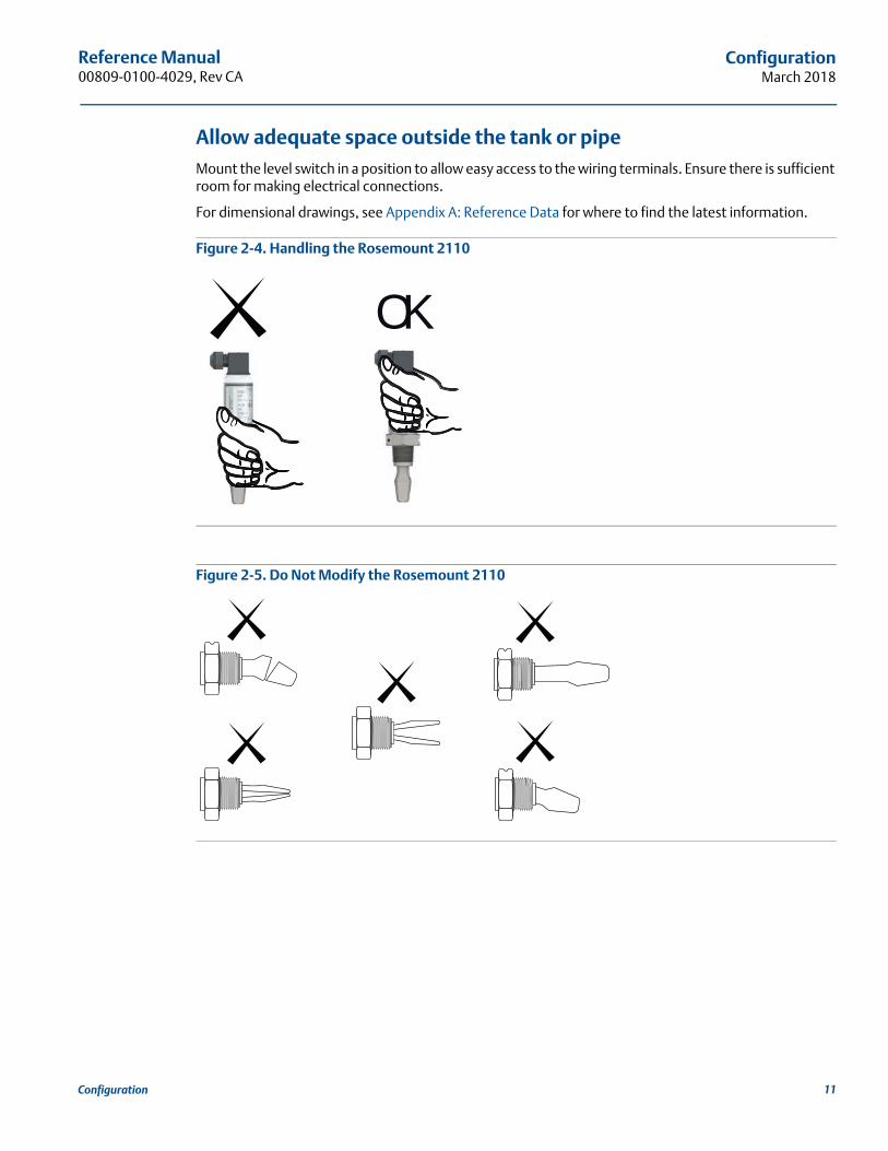
How to handle the level switchDo not hold using the forks (Figure 2-4 on page 11).
Device identificationTo identify the Rosemount 2110 version, see the label on the housing.
Mounting orientationMount the level switch at any angle that allows the liquid level to rise or flow through the fork gap(Figure 2-7 and Figure 2-8 on page 14).
SP
HYSP
0.1 in.(2.5 mm)
0.5 in.(13 mm)
0.5 in.(13 mm)
10 Configuration
Reference Manual 00809-0100-4029, Rev CA
ConfigurationMarch 2018
Allow adequate space outside the tank or pipeMount the level switch in a position to allow easy access to the wiring terminals. Ensure there is sufficient room for making electrical connections.
For dimensional drawings, see Appendix A: Reference Data for where to find the latest information.
Figure 2-4. Handling the Rosemount 2110
Figure 2-5. Do Not Modify the Rosemount 2110
OK
11Configuration
Reference Manual00809-0100-4029, Rev CA
ConfigurationMarch 2018
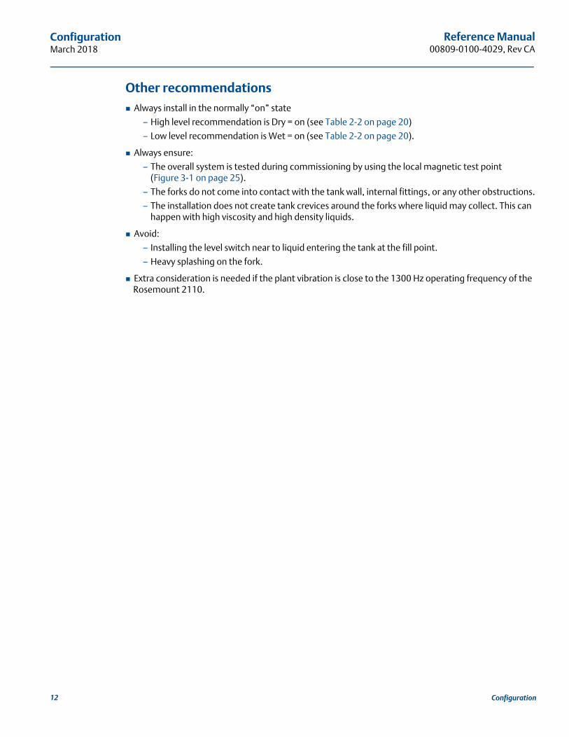
Other recommendations Always install in the normally “on” state
– High level recommendation is Dry = on (see Table 2-2 on page 20)
– Low level recommendation is Wet = on (see Table 2-2 on page 20).
Always ensure:
– The overall system is tested during commissioning by using the local magnetic test point (Figure 3-1 on page 25).
– The forks do not come into contact with the tank wall, internal fittings, or any other obstructions.
– The installation does not create tank crevices around the forks where liquid may collect. This can happen with high viscosity and high density liquids.
Avoid:
– Installing the level switch near to liquid entering the tank at the fill point.
– Heavy splashing on the fork.
Extra consideration is needed if the plant vibration is close to the 1300 Hz operating frequency of the Rosemount 2110.
12 Configuration
Reference Manual 00809-0100-4029, Rev CA
ConfigurationMarch 2018
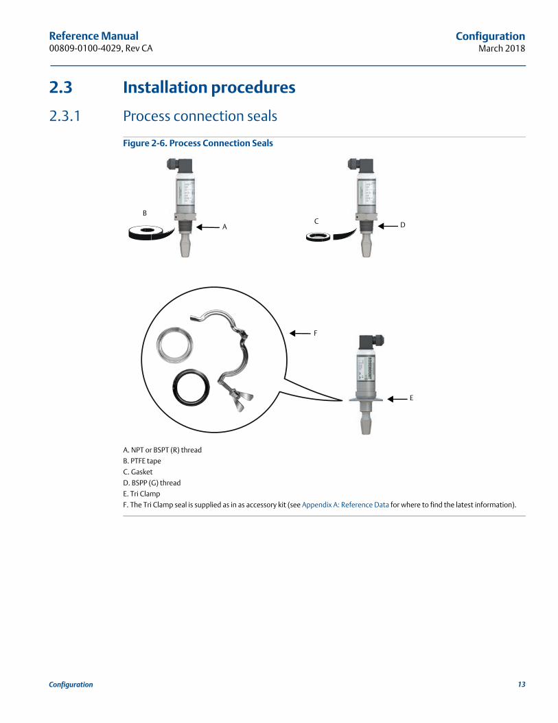
2.3 Installation procedures
2.3.1 Process connection seals
Figure 2-6. Process Connection Seals
A. NPT or BSPT (R) thread
B. PTFE tape
C. Gasket
D. BSPP (G) thread
E. Tri Clamp
F. The Tri Clamp seal is supplied as in as accessory kit (see Appendix A: Reference Data for where to find the latest information).
B
A
E
C
EF
D
13Configuration
Reference Manual00809-0100-4029, Rev CA
ConfigurationMarch 2018
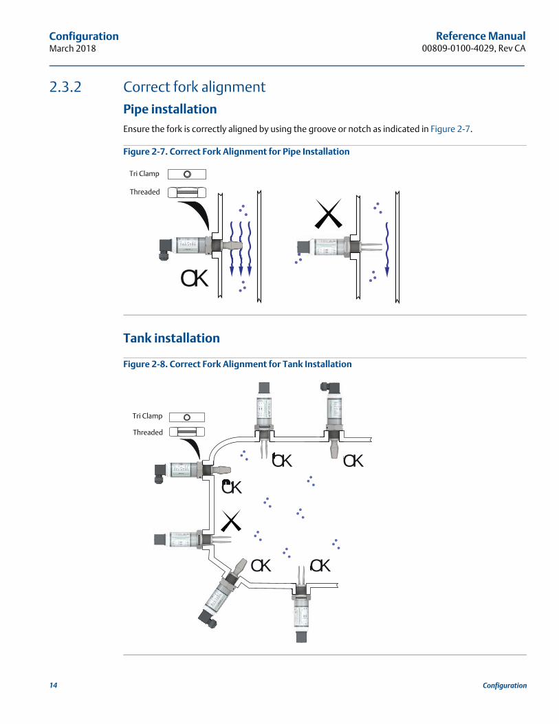
2.3.2 Correct fork alignment
Pipe installationEnsure the fork is correctly aligned by using the groove or notch as indicated in Figure 2-7.
Figure 2-7. Correct Fork Alignment for Pipe Installation
Tank installation
Figure 2-8. Correct Fork Alignment for Tank Installation
OK
Tri Clamp
Threaded
OKOK
OK
OK OK
Tri Clamp
Threaded
14 Configuration
Reference Manual 00809-0100-4029, Rev CA
ConfigurationMarch 2018
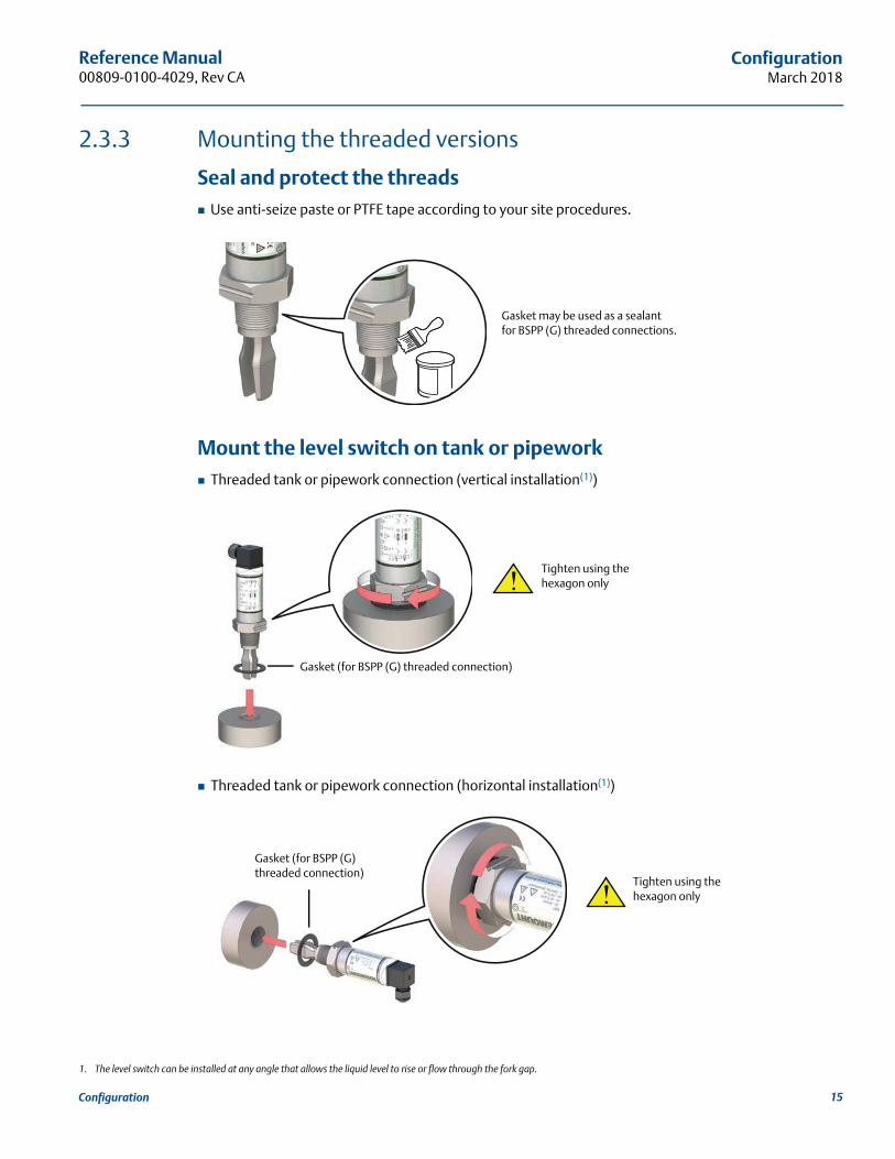
2.3.3 Mounting the threaded versions
Seal and protect the threads Use anti-seize paste or PTFE tape according to your site procedures.
Mount the level switch on tank or pipework Threaded tank or pipework connection (vertical installation(1))
Threaded tank or pipework connection (horizontal installation(1))
1. The level switch can be installed at any angle that allows the liquid level to rise or flow through the fork gap.
Gasket may be used as a sealantfor BSPP (G) threaded connections.
Gasket (for BSPP (G) threaded connection)
Tighten using the hexagon only
Gasket (for BSPP (G) threaded connection)
Tighten using the hexagon only
15Configuration
Reference Manual00809-0100-4029, Rev CA
ConfigurationMarch 2018
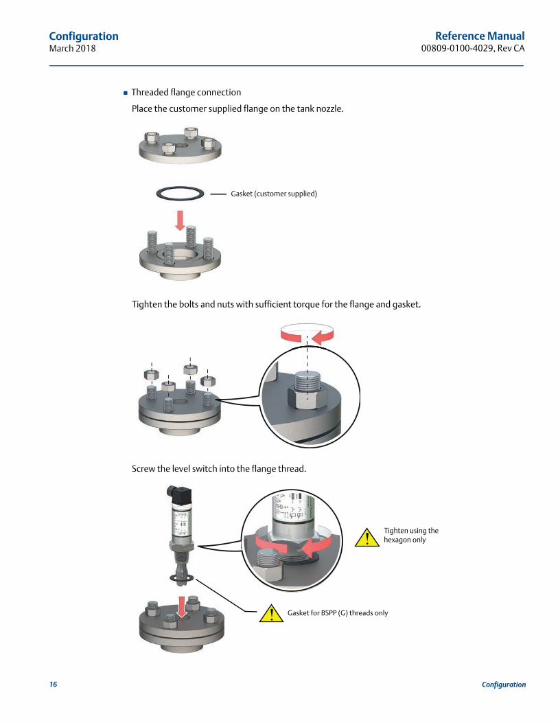
Threaded flange connection
Place the customer supplied flange on the tank nozzle.
Tighten the bolts and nuts with sufficient torque for the flange and gasket.
Screw the level switch into the flange thread.
Gasket (customer supplied)
Gasket for BSPP (G) threads only
Tighten using the hexagon only
16 Configuration
Reference Manual 00809-0100-4029, Rev CA
ConfigurationMarch 2018
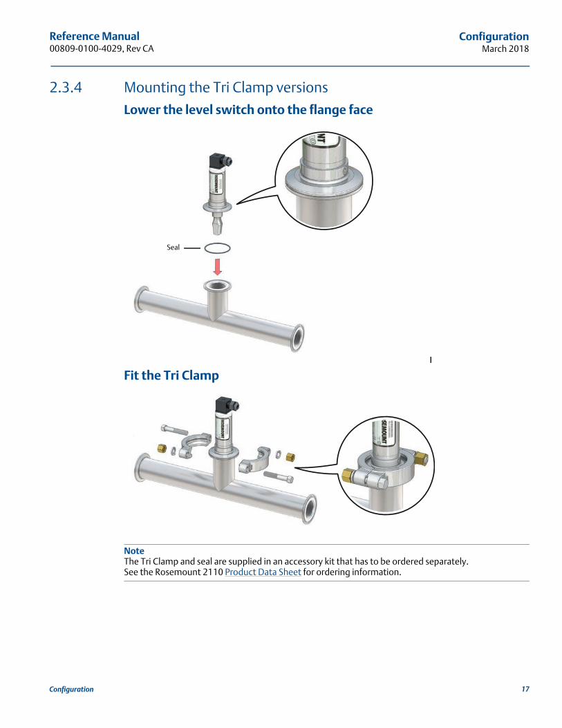
2.3.4 Mounting the Tri Clamp versions
Lower the level switch onto the flange face
Fit the Tri Clamp
NoteThe Tri Clamp and seal are supplied in an accessory kit that has to be ordered separately. See the Rosemount 2110 Product Data Sheet for ordering information.
Seal
17Configuration
Reference Manual00809-0100-4029, Rev CA
ConfigurationMarch 2018
2.4 Electrical installation
2.4.1 Prepare the electrical connections
Cable selectionTwisted-pairs and shielded wiring is recommended for environments with high EMI (electromagnetic interference). Two wires can be safely connected to each terminal screw. Maximum wire size is 15 AWG.
Cable glandThe cable gland is integrated in the four-position plug of the level switch.Do not make any modifications to the level switch.
Power supplyThe Direct Load electronics option operates on 21 - 264 Vdc or 21 - 264 Vac (50/60 Hz) at the level switch terminals.
The PNP electronics option operates on 18 - 60 Vdc at the level switch terminals.
Mode selectionTable 2-1 on page 19 shows how the mode selection is determined from the wiring connections. Modes are “Dry on, high level alarm” and “Wet on, low level alarm”.
FunctionsTable 2-2 on page 20 shows the switched electrical outputs from the PNP and Direct Load electronics for each mode selection.
NoteFor direct load switching, a DPST (Double Pole, Single Throw) (on/off) switch must also be fitted for safe disconnection of the power supply. Fit the DPST switch as near to the Rosemount 2110 as possible, keeping the switch free of obstructions. Label the switch to indicate it is the supply disconnection device for the Rosemount 2110.
18 Configuration
Reference Manual 00809-0100-4029, Rev CA
ConfigurationMarch 2018
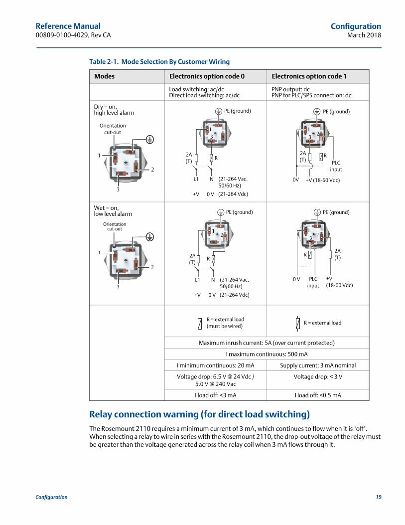
Table 2-1. Mode Selection By Customer Wiring
Relay connection warning (for direct load switching)The Rosemount 2110 requires a minimum current of 3 mA, which continues to flow when it is ‘off’. When selecting a relay to wire in series with the Rosemount 2110, the drop-out voltage of the relay must be greater than the voltage generated across the relay coil when 3 mA flows through it.
Modes Electronics option code 0 Electronics option code 1
Load switching: ac/dcDirect load switching: ac/dc
PNP output: dcPNP for PLC/SPS connection: dc
Dry = on, high level alarm
Wet = on, low level alarm
Maximum inrush current: 5A (over current protected)
I maximum continuous: 500 mA
I minimum continuous: 20 mA Supply current: 3 mA nominal
Voltage drop: 6.5 V @ 24 Vdc / 5.0 V @ 240 Vac
Voltage drop: < 3 V
I load off: <3 mA I load off: <0.5 mA
Orientation cut-out
2
3
1
PE (ground)
2A(T)
R
L1 N (21-264 Vac,50/60 Hz)
+V 0 V (21-264 Vdc)
13
13
R2A(T)
2
0V +V (18-60 Vdc)
PLCinput
PE (ground)
Orientation cut-out
2
3
1
1
R2A(T)
2
L1 N (21-264 Vac,50/60 Hz)
+V 0 V (21-264 Vdc)
PE (ground)
1
3
R2A(T)
2
0 V +V (18-60 Vdc)
PLCinput
PE (ground)
R = external load(must be wired)
R = external load
19Configuration
Reference Manual00809-0100-4029, Rev CA
ConfigurationMarch 2018
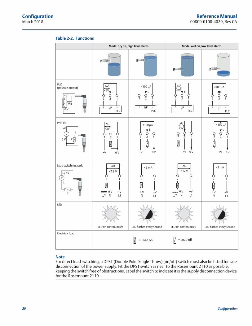
Table 2-2. Functions
NoteFor direct load switching, a DPST (Double Pole, Single Throw) (on/off) switch must also be fitted for safe disconnection of the power supply. Fit the DPST switch as near to the Rosemount 2110 as possible, keeping the switch free of obstructions. Label the switch to indicate it is the supply disconnection device for the Rosemount 2110.
Mode: dry on, high level alarm Mode: wet on, low level alarm
PLC (positive output)
PNP dc
Load switching ac/dc
LED
LED on continuously LED flashes every second LED on continuously LED flashes every second
Electrical load
+V
0 V
SigPLC
<3V
3 2 1
L
U
+ –I/PPLC
13 2
L
+ –I/PPLC
<100 A<3V
32
L
U
+ –I/PPLC
1
+ –I/PPLC
2 3 1
L
<100 A
+V
0 V
V
R
IL
<3V
3 2 1
U
+V 0 V
L
<100 A
+V 0 V
3 2 1
<3V
3 2 1
U
+V 0 V
3 2 1
L
<100 A
+V 0 V
V
R
IL
L / +V <12 V
U
3 1
+V0 VN L1
+V0 VN L1
3 1
<3 mA
+V0 VN L1
<12 V
U
2 1
+V0 VN L1
2 1
<3 mA
= Load on = Load off
20 Configuration
Reference Manual 00809-0100-4029, Rev CA
ConfigurationMarch 2018
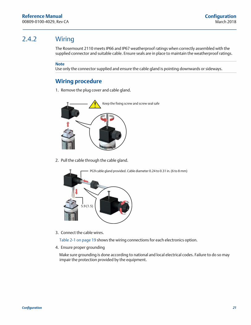
2.4.2 WiringThe Rosemount 2110 meets IP66 and IP67 weatherproof ratings when correctly assembled with the supplied connector and suitable cable. Ensure seals are in place to maintain the weatherproof ratings.
NoteUse only the connector supplied and ensure the cable gland is pointing downwards or sideways.
Wiring procedure1. Remove the plug cover and cable gland.
2. Pull the cable through the cable gland.
3. Connect the cable wires.
Table 2-1 on page 19 shows the wiring connections for each electronics option.
4. Ensure proper grounding
Make sure grounding is done according to national and local electrical codes. Failure to do so may impair the protection provided by the equipment.
Keep the fixing screw and screw seal safe
PG9 cable gland provided. Cable diameter 0.24 to 0.31 in. (6 to 8 mm)
5.9 (1.5)
21Configuration

Reference Manual00809-0100-4029, Rev CA
ConfigurationMarch 2018
Signal cable shield grounding at power supply endMake sure the instrument cable shield is:
Trimmed close and insulated from touching the level switch housing.
Connected to the next shield if cable is routed through a junction box.
Connected to a good earth ground at the power supply end.
Figure 2-9. Cable Shield Connection (Power Supply End)
A. Trim shield and insulate C. Trim shield
B. Minimize distance D. Connect shield back to power supply ground
Signal cable shield grounding at level switch endMake sure the instrument cable shield is:
Trimmed close and insulated at the power supply end.
Connected to the next shield if cable is routed through a junction box.
Connected to the potential earth (ground) terminal.
Figure 2-10. Cable Shield Connection (Level Switch End)
A. Trim shield and insulate C. Trim shield
B. Minimize distance D. Connect shield back to power supply ground
A
B
B
C C D
A
B
D
C C
22 Configuration
Reference Manual 00809-0100-4029, Rev CA
ConfigurationMarch 2018
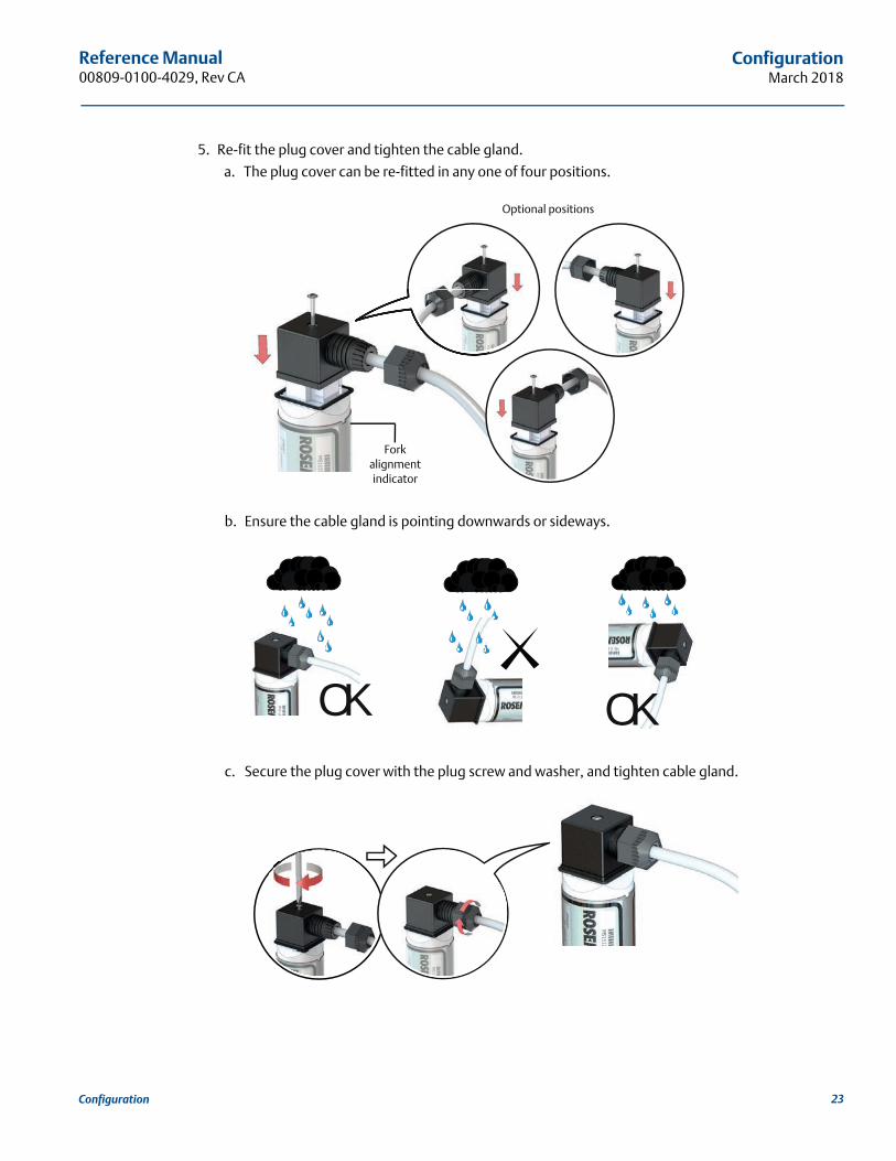
5. Re-fit the plug cover and tighten the cable gland.
a. The plug cover can be re-fitted in any one of four positions.
b. Ensure the cable gland is pointing downwards or sideways.
c. Secure the plug cover with the plug screw and washer, and tighten cable gland.
Optional positions
Fork alignment indicator
OK OK
23Configuration
Reference Manual00809-0100-4029, Rev CA
ConfigurationMarch 2018
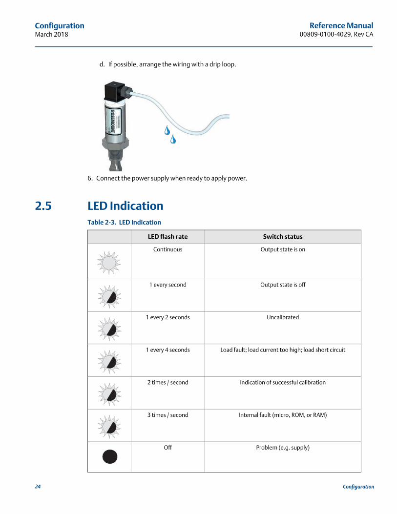
d. If possible, arrange the wiring with a drip loop.
6. Connect the power supply when ready to apply power.
2.5 LED IndicationTable 2-3. LED Indication
LED flash rate Switch status
Continuous Output state is on
1 every second Output state is off
1 every 2 seconds Uncalibrated
1 every 4 seconds Load fault; load current too high; load short circuit
2 times / second Indication of successful calibration
3 times / second Internal fault (micro, ROM, or RAM)
Off Problem (e.g. supply)
24 Configuration
Reference Manual 00809-0100-4029, Rev CA
InstallationMarch 2018
Section 3 Troubleshooting
Magnetic test point . . . . . . . . . . . . . . . . . . . . . . . . . . . . . . . . . . . . . . . . . . . . . . . . . . . . . . . . . . . . . . . page 25Inspection . . . . . . . . . . . . . . . . . . . . . . . . . . . . . . . . . . . . . . . . . . . . . . . . . . . . . . . . . . . . . . . . . . . . . . . page 25Maintenance . . . . . . . . . . . . . . . . . . . . . . . . . . . . . . . . . . . . . . . . . . . . . . . . . . . . . . . . . . . . . . . . . . . . . page 26Troubleshooting . . . . . . . . . . . . . . . . . . . . . . . . . . . . . . . . . . . . . . . . . . . . . . . . . . . . . . . . . . . . . . . . . . page 26Spare parts . . . . . . . . . . . . . . . . . . . . . . . . . . . . . . . . . . . . . . . . . . . . . . . . . . . . . . . . . . . . . . . . . . . . . . page 26Service support . . . . . . . . . . . . . . . . . . . . . . . . . . . . . . . . . . . . . . . . . . . . . . . . . . . . . . . . . . . . . . . . . . . page 27
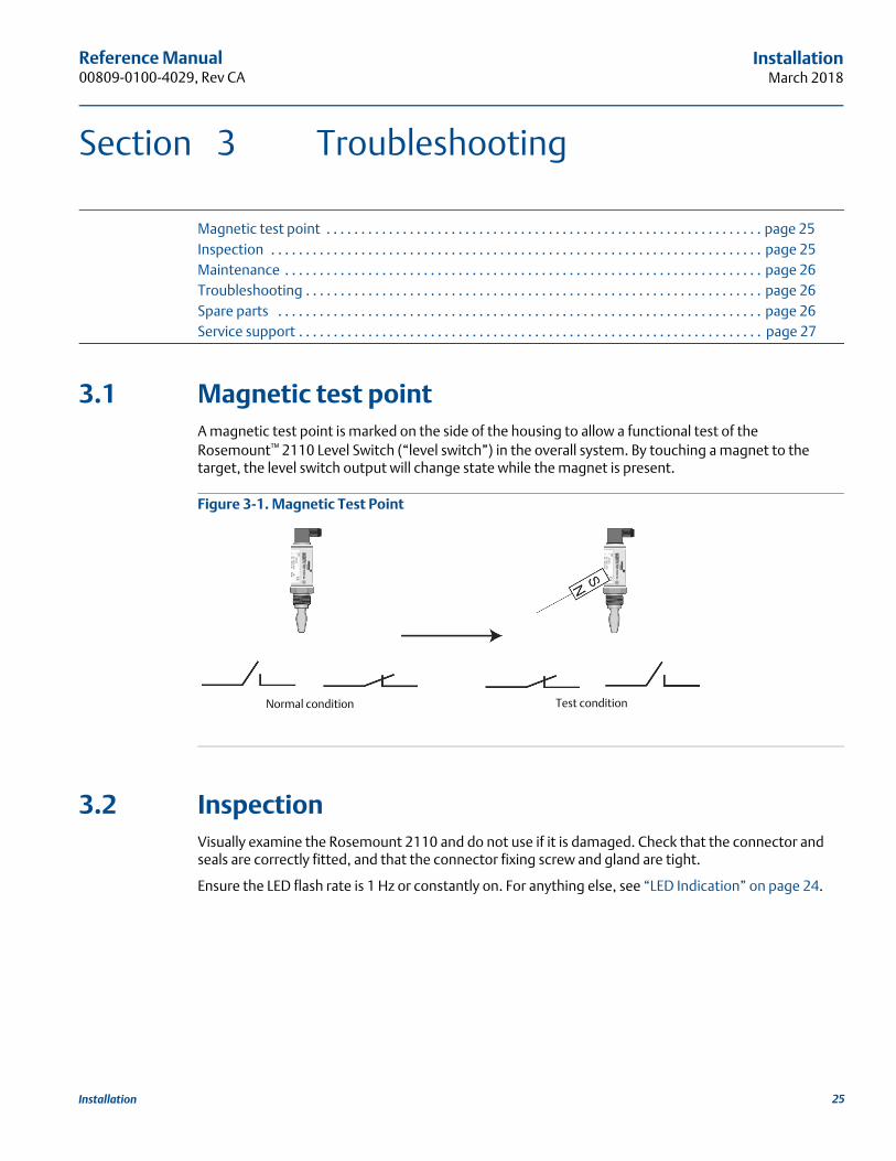
3.1 Magnetic test pointA magnetic test point is marked on the side of the housing to allow a functional test of the Rosemount™ 2110 Level Switch (“level switch”) in the overall system. By touching a magnet to the target, the level switch output will change state while the magnet is present.
Figure 3-1. Magnetic Test Point
3.2 InspectionVisually examine the Rosemount 2110 and do not use if it is damaged. Check that the connector and seals are correctly fitted, and that the connector fixing screw and gland are tight.
Ensure the LED flash rate is 1 Hz or constantly on. For anything else, see “LED Indication” on page 24.
Normal condition Test condition
25Installation
Reference Manual00809-0100-4029, Rev CA
InstallationMarch 2018
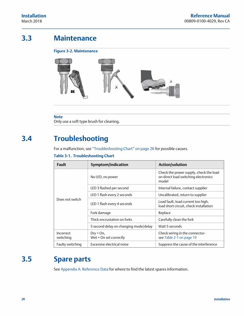
3.3 Maintenance
Figure 3-2. Maintenance
NoteOnly use a soft type brush for cleaning.
3.4 TroubleshootingFor a malfunction, see “Troubleshooting Chart” on page 26 for possible causes.
Table 3-1. Troubleshooting Chart
3.5 Spare partsSee Appendix A: Reference Data for where to find the latest spares information.
Fault Symptom/indication Action/solution
Does not switch
No LED, no powerCheck the power supply, check the load on direct load switching electronics model
LED 3 flashed per second Internal failure, contact supplier
LED 1 flash every 2 seconds Uncalibrated, return to supplier
LED 1 flash every 4 secondsLoad fault, load current too high, load short circuit, check installation
Fork damage Replace
Thick encrustation on forks Carefully clean the fork
5 second delay on changing mode/delay Wait 5 seconds
Incorrect switching
Dry = On, Wet = On set correctly
Check wiring in the connector-see Table 2-1 on page 19
Faulty switching Excessive electrical noise Suppress the cause of the interference
26 Installation
Reference Manual 00809-0100-4029, Rev CA
InstallationMarch 2018
3.6 Service supportTo expedite the return process outside of the United States, contact the nearest Emerson™ representa-tive.
Within the United States, call the Emerson Instrument and Valves Response Center using the 1 800 654 7768 toll-free number. This center, available 24 hours a day, will assist you with any needed information or materials.
The center will ask for product model and serial numbers, and will provide a Return Material Authorization (RMA) number. The center will also ask for the process material to which the product was last exposed.
Individuals who handle products exposed to a hazardous substance can avoid injury if they are informed of, and understand, the hazard. If the product being returned was exposed to a hazardous substance as defined by OSHA, a copy of the required Safety Data Sheet (SDS) for each hazardous substance identified must be included with the returned goods.
27Installation

Reference Manual00809-0100-4029, Rev CA
InstallationMarch 2018
28 Installation
Reference Manual 00809-0100-4029, Rev CA
Specifications and Reference DataMarch 2018
Specifications and Reference Data 29
Appendix A Reference Data
A.1 Product CertificationsTo view current Rosemount™ 2110 Product Certifications, follow these steps:
1. Go to Emerson.com/Rosemount.
2. In the Products section, click Level Measurement and then View Products.
3. Click Rosemount 2110 Level Switch - Vibrating Fork to view the product details page.
4. Scroll as needed to the green menu bar and clickDocuments & Drawings.
5. Click Manuals & Guides.
6. Select the Quick Start Guide.
A.2 Ordering Information, Specifications, and Drawings
To view current Rosemount 2110 Ordering Information, Specifications, and Drawings, follow these steps:
1. Go to Emerson.com/Rosemount.
2. In the Products section, click Level Measurement and then View Products.
3. Click Rosemount 2110 Level Switch - Vibrating Fork to view the product details page.
4. Scroll as needed to the green menu bar and clickDocuments & Drawings.
5. For installation drawings, click Drawings & Schematics and select the appropriate document.
6. For ordering information, specifications, and dimensional drawings, click Data Sheets & Bulletins and select the appropriate Product Data Sheet.
Specifications and Reference DataMarch 2018
Reference Manual 00809-0100-4029, Rev CA
Specifications and Reference Data 30


Reference Manual00809-0100-4029, Rev CA
March 2018
Global HeadquartersEmerson Automation Solutions 6021 Innovation Blvd.Shakopee, MN 55379, USA
+1 800 999 9307 or +1 952 906 8888+1 952 949 7001 [email protected]
North America Regional OfficeEmerson Automation Solutions8200 Market Blvd.Chanhassen, MN 55317, USA
+1 800 999 9307 or +1 952 906 8888+1 952 949 7001 [email protected]
Latin America Regional OfficeEmerson Automation Solutions1300 Concord Terrace, Suite 400Sunrise, FL 33323, USA
+1 954 846 5030+1 954 846 [email protected]
Europe Regional OfficeEmerson Automation SolutionsNeuhofstrasse 19a P.O. Box 1046CH 6340 BaarSwitzerland
+41 (0) 41 768 6111+41 (0) 41 768 6300 [email protected]
Asia Pacific Regional OfficeEmerson Automation Solutions1 Pandan CrescentSingapore 128461
+65 6777 8211+65 6777 0947 [email protected]
Middle East and Africa Regional OfficeEmerson Automation SolutionsEmerson FZE P.O. Box 17033Jebel Ali Free Zone - South 2Dubai, United Arab Emirates
+971 4 8118100+971 4 8865465 [email protected]
Linkedin.com/company/Emerson-Automation-Solutions
Twitter.com/Rosemount_News
Facebook.com/Rosemount
Youtube.com/user/RosemountMeasurement
Google.com/+RosemountMeasurement
Standard Terms and Conditions of Sale are available upon request.The Emerson logo is a trademark and service mark of Emerson Electric Co.Rosemount is a mark of one of the Emerson family of companies.All other marks are the property of their respective owners.© 2018 Emerson. All rights reserved.