Embed Size (px)
Citation preview

1
BARNSTEAD|THERMOLYNE CORPORATION
ROpure® Infinity Premier ModelReverse Osmosis System
OPERATING MANUAL
AND PARTS LIST
Series 901
Model Description Liters/Hour VoltageD9011 Premier 15 l/hr 120D9014 Premier 30 l/hr 120D9012-33 Premier 15 l/hr 230D9015-33 Premier 30 l/hr 230D9013 Premier 15 l/hr 100
LT901X4 • 5/8/98
2
Table of Contents
Safety Information .............................................................................................................................................. 4Alert Signals ................................................................................................................................................ 4Warnings ...................................................................................................................................................... 4
Introduction ........................................................................................................................................................ 6Specifications ..................................................................................................................................................... 7
Dimensions and Clearance Requirements .................................................................................................. 7Feed Water Requirements ........................................................................................................................... 7Product Water .............................................................................................................................................. 7
Membrane Rejection Rates ................................................................................................................... 7Electrical Requirements ............................................................................................................................... 8Environmental Conditions ............................................................................................................................ 8Declaration of Conformity ............................................................................................................................ 8
Unpackaging and Installation ............................................................................................................................. 9Unpackaging ................................................................................................................................................ 9Choosing a Site ........................................................................................................................................... 9Tubing Adapter Installation ........................................................................................................................ 10Bench Mounting ......................................................................................................................................... 11Wall Mounting ............................................................................................................................................ 11Water Connections .................................................................................................................................... 12
Feed Water Connection ...................................................................................................................... 12Reject Water Connection .................................................................................................................... 12Product Water Connection to D9021 Storage Reservoir .................................................................... 13
Cartridge and Membrane Installation ........................................................................................................ 13Prefilter Installation .............................................................................................................................. 14Pretreatment Carbon Cartridge Installation ......................................................................................... 15MPS Installation .................................................................................................................................. 15Membrane Installation ......................................................................................................................... 17
Controls ............................................................................................................................................................ 20Main Power Switch .................................................................................................................................... 20Control Panel ............................................................................................................................................. 20Switches .................................................................................................................................................... 21
Initial Operation ................................................................................................................................................ 22Check and/or Change Chlorine Level ........................................................................................................ 22Flushing the Membrane or Membranes .................................................................................................... 24
Normal Operation ............................................................................................................................................. 25Reading the Purity of Product Water and Inlet Water ................................................................................ 25Mode Menu ................................................................................................................................................ 26Resetting the Carbon Timer ....................................................................................................................... 27Resetting the MPS Timer ........................................................................................................................... 28Pressure Gauges ....................................................................................................................................... 29Standby Mode ........................................................................................................................................... 30Selecting the Percent Rejection Set Point ................................................................................................. 30Low Pressure ............................................................................................................................................. 31Error Messages ......................................................................................................................................... 31Other Status Messages ............................................................................................................................. 32

3
TABLE OF CONTENTS
Maintenance..................................................................................................................................................... 33Caring for Your ROpure Infinity ................................................................................................................. 33System Sanitization ................................................................................................................................... 33General Cleaning Instructions ................................................................................................................... 34
Service and Repair ........................................................................................................................................... 35Normal Unit Operation ............................................................................................................................... 35Mains Fuse Replacement .......................................................................................................................... 36Transformer Fuse Replacement ................................................................................................................ 36Membrane Replacement ........................................................................................................................... 37Prefilter Replacement ................................................................................................................................ 37Carbon Replacement ................................................................................................................................. 38MPS Replacement ..................................................................................................................................... 39Shutdown ................................................................................................................................................... 39
Problem Solving ............................................................................................................................................... 40Replacement Parts ........................................................................................................................................... 41Flow Diagram ................................................................................................................................................... 43Operating Log .................................................................................................................................................. 44Ordering Procedures ........................................................................................................................................ 45One Year Limited Warranty .............................................................................................................................. 47
4
Safety Information
Your Barnstead|Thermolyne ROpure Infinity hasbeen designed with function, reliability, and safetyin mind. It is your responsibility to install it inconformance with local electrical codes. Thismanual contains important safety information.You must carefully read and understand thecontents of this manual prior to the use of thisequipment. For safe operation, please payattention to the alert indicators throughout themanual.
Water purification technology employs one ormore of the following: chemicals, electrical de-vices, mercury vapor lamps, steam and heatedvessels. Care should be taken when installing,operating or servicing Barnstead products. Thespecific safety notes pertinent to this Barnsteadproduct are listed below.
WarningsTo avoid electrical shock, always: 1. Use a properly grounded electrical outlet
of correct voltage and current handlingcapacity.
2. Do not locate the ROpure Infinity directlyover equipment that requires electricalservice. Routine maintenance of this unitmay involve water spillage andsubsequent electrical shock hazard ifimproperly located.
3. Replace fuses with those of the sametype and rating.
4. Disconnect from the power supply priorto maintenance and servicing.
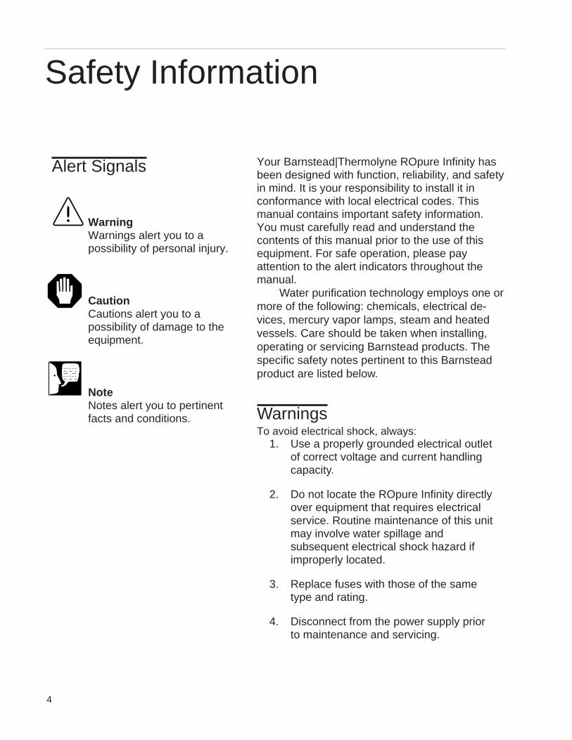
WarningWarnings alert you to apossibility of personal injury.
CautionCautions alert you to apossibility of damage to theequipment.
NoteNotes alert you to pertinentfacts and conditions.
Alert Signals
5
To avoid personal injury:1. Do not use in the presence of
flammable or combustible materials;fire or explosion may result. Thisdevice contains components whichmay ignite such materials.
2. This device is to be used with waterfeeds only. Sanitizing/cleaning agentsmust be used in compliance withinstructions in this manual. Failure tocomply with the above could result inexplosion and personal injury.
3. Avoid splashing disinfecting solutionson clothing or skin.
4. Ensure all piping connections aretight to avoid chemical leakage.
5. Ensure adequate ventilation.
6. Carefully follow manufacturer’s safetyinstructions on labels of chemicalcontainers and material safety datasheets.
7. Depressurize system prior todisengaging the cartridge hold-downbracket or membrane removal.
8. Refer servicing to qualified personnel.
9. Avoid contact of strong oxidizingagents, such as nitric acid, with ionexchange cartridges. An explosionmay result.
SAFETY INFORMATION
6
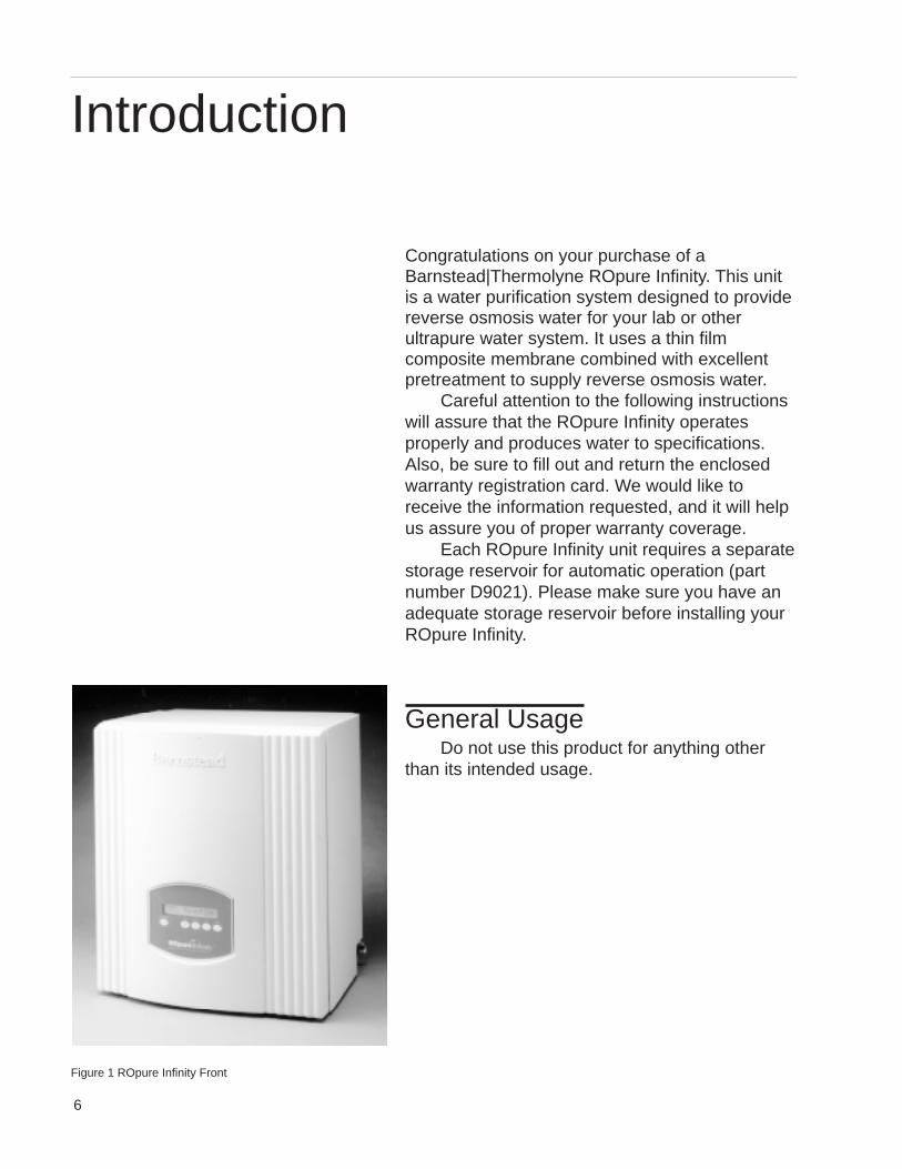
Congratulations on your purchase of aBarnstead|Thermolyne ROpure Infinity. This unitis a water purification system designed to providereverse osmosis water for your lab or otherultrapure water system. It uses a thin filmcomposite membrane combined with excellentpretreatment to supply reverse osmosis water.
Careful attention to the following instructionswill assure that the ROpure Infinity operatesproperly and produces water to specifications.Also, be sure to fill out and return the enclosedwarranty registration card. We would like toreceive the information requested, and it will helpus assure you of proper warranty coverage.
Each ROpure Infinity unit requires a separatestorage reservoir for automatic operation (partnumber D9021). Please make sure you have anadequate storage reservoir before installing yourROpure Infinity.
General UsageDo not use this product for anything other
than its intended usage.
Introduction
Figure 1 ROpure Infinity Front
7
Dimensions and Clearance Requirements
DimensionsWall and Bench mounted models
Width 20” (50.8 cm)Depth 17-1/2” (44.5 cm)Height 22-5/8” (57.5 cm)
ClearancesSides - 6” (15 cm) minimum for servicing.Above - 3” (7.6 cm) minimum for removal of the outer case.Front - 20” (50.8 cm) minimum for opening the front door.
Cartridge and membrane replacement is easily accomplished upon opening the front door.
Feed Water Requirements1,5
Types1 Tap (Potable).Turbidity 1.0 N.T.U. maximum.Pressure Range 30 psig (2 bar) to 100 psig (6.8 bar) maximum.Temperature Range 4.4°C - 31°C (40-88°F)Inlet Flow Requirements 154 lphpH 4-11TDS (Max. ppm as CaCO3) 500Silt Density Index <5%Free Chlorine <0.1 ppm2
Langlier Saturation Index NegativeIron (Total as Fe) <0.5 ppm
Product Water5
Product Water Flow Rate 15 lph3 or 303 lph maximum at minimum inlet feed waterpressure of 30 psig at 60 Hz
% Recovery 25%
Membrane Rejection Rates 4
Monovalent Ions 90-95%
Polyvalent Ions 95-99%Particles >99%Microorganisms >99%Dissolved Organics (300 MW) >99%Reject Water Flow Rate 124-139 lph
Specifications
1 Feed water suitability must be determined by a wateranalysis.
2 Free chlorine removed by pretreatment cartridge.3 ±15%, feed water at 25°C and 60 psig operating pressure.4 Membrane performance is dependent on condition, pressure,
recovery, water temperature and water composition. Listedmembrane performance for a new membrane is based onoptimum operating conditions of 60 psig, 15% recovery,25°C (77°F) feed water temperature and feed watercomposition of a maximum of 500 ppm NaCl at a pH of 6.0-6.5.
5 Membrane performance, flow rates and recovery informationare nominal values. Variations in the feed water temperature,pumps and reject orifice may slightly alter these results.
8
Electrical RequirementsThe ROpure Infinity is equipped with a power cord to be plugged into an electrical outlet ofthe appropriate voltage.Voltage and Frequency (Nominal)Model D9013 100 VAC, 50-60 Hz 85-110 VAC, 47-63 Hz, 1 phaseModel D9011, D9014 120 VAC, 50-60 Hz 98-127 VAC, 47-63 Hz, 1 phaseModel D9012-33, D9015-33 230 VAC, 50-60 Hz 196-253 VAC, 47-63 Hz, 1 phase
Environmental ConditionsOperating: 4°C - 49°C; 20% to 80% relative humidity, non-condensing. Installation
Category II (over-voltage) in accordance with IEC 664. Pollution Degree 2 inaccordance with IEC 664. Altitude limit: 3,500 meters.
Storage: -25°C to 65°C; 10% to 85% relative humidity.
Declaration of Conformity (-33 models only)Barnstead|Thermolyne hereby declares under its sole responsibility that this product con-forms with the technical requirements of the following standards:
EMC: EN 50081-1 Generic Emission Standard;EN 50082-1 Generic Immunity Standard;EN 61326 Electrical equipment for measurement, control and
laboratory use - EMC requirements - Part 1: GeneralRequirements
Safety: EN61010-1 Safety requirements for electrical equipment formeasurement, control, and laboratory use;Part I: General Requirements
per the provisions of the Electromagnetic Compatability Directive 89/336/EEC, as amendedby 92/31/EEC and 93/68/EEC, and per the provisions of the Low Voltage Directive 73/23/EEC, as amended by 93/68/EEC.
The authorized representative located within the European Community is:European ManagerBarnstead|ThermolyneSaarbrückener Str. 248D-38116 BraunschweigGermany
Copies of the Declaration of Conformity are available upon request.
SPECIFICATIONS
9
Unpackaging1. Remove the unit from its shipping
container. Remove all contents carefully.Ensure the following parts areremoved from the packagingmaterials before discarding.1) Membrane(s)2) Prefilter cartridge3) MPS cartridge4) Wall bracket5) Accessory parts bag with feed
water tube included6) Power cord
2. Put the ROpure Infinity on a bench.
Choosing a SiteThe ROpure Infinity system features a pivotingcontrol panel display which allows the systemto be mounted almost anywhere within thelaboratory. Your ROpure Infinity must belocated within six feet of an electrical outletappropriate for your unit, within five feet of yourfeed water supply and close to anatmospherically vented drain. If you are usingthe accessory 60 Liter Infinity StorageReservoir (part number D9021), the reservoirmust not be mounted farther than four feetaway from the ROpure Infinity.
Use the wall bracket for wall mountedsystems as a template to drill mounting holes.(The ROpure Infinity does not include screwsand fasteners for mounting.) Allow a minimumof 6 inches (15 cm) clearance on all sides ofthe unit for servicing, 3 inches (7.6 cm) on topfor outer case removal and 20 inches (50.8 cm)in front for opening the door.
Unpackaging and InstallationCautionWall composition, conditionand construction, as well asfastener type, must beconsidered when mountingthis unit. The mountingsurface and fastenersselected must be capable ofsupporting a minimum of 275lbs. Inadequate support and/or fasteners may result indamage to mounting surfaceand/or equipment. If you areunsure of mounting surfacecomposition, condition andconstruction or correctfasteners, consult yourbuilding maintenance groupor contractor.
WarningDo not locate the ROpure Infinitydirectly over equipment thatrequires electrical service.Routine maintenance of this unitmay involve water spillage andsubsequent electrical shockhazard if improperly located.
Do not use in the presence offlammable or combustiblematerials; fire or explosion mayresult. The device containscomponents which may ignitesuch materials.
10
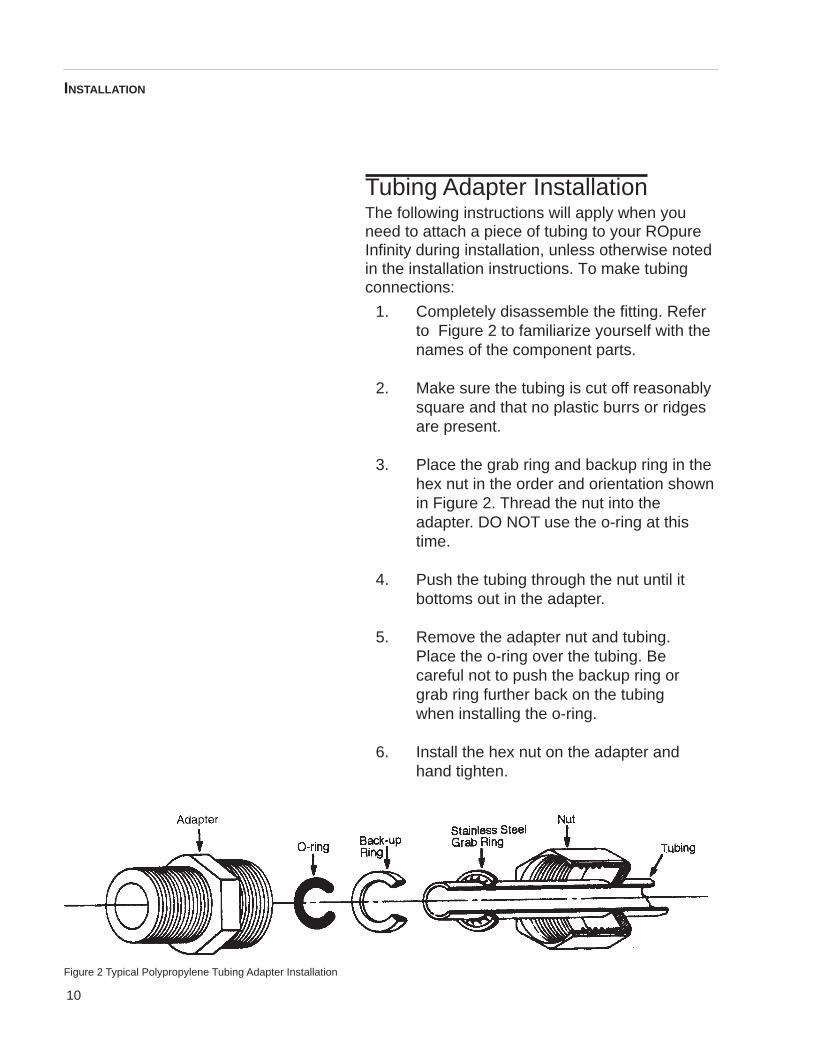
Tubing Adapter InstallationThe following instructions will apply when youneed to attach a piece of tubing to your ROpureInfinity during installation, unless otherwise notedin the installation instructions. To make tubingconnections:
1. Completely disassemble the fitting. Referto Figure 2 to familiarize yourself with thenames of the component parts.
2. Make sure the tubing is cut off reasonablysquare and that no plastic burrs or ridgesare present.
3. Place the grab ring and backup ring in thehex nut in the order and orientation shownin Figure 2. Thread the nut into theadapter. DO NOT use the o-ring at thistime.
4. Push the tubing through the nut until itbottoms out in the adapter.
5. Remove the adapter nut and tubing.Place the o-ring over the tubing. Becareful not to push the backup ring orgrab ring further back on the tubingwhen installing the o-ring.
6. Install the hex nut on the adapter andhand tighten.
Figure 2 Typical Polypropylene Tubing Adapter Installation
INSTALLATION
11
Bench Mounting1. Place ROpure Infinity on a bench top that
is accessible to water and electricity andthat is convenient to your work area,noting clearance requirements.
Wall MountingInstall the NANOpure Infinity on a wall in aconvenient location that is accessible to waterand electricity.
1. Locate the wall bracket packedseparately from the unit.
2. Using the wall bracket as a template,locate and drill the mounting holes inthe wall. A minimum of four(customer-supplied) fasteners will berequired — two on the top and two on thebottom.
3. Attach the wall bracket to the wall usingthe customer-supplied fasteners.
4. Remove the locking screws on each sideof the wall bracket.
5. Pull the two locking slides on each sideof the wall bracket out as far as theywill go.
6. Hang the Infinity unit on the wall bracketby sliding the mounting pins into the wallbracket slots.
7. Push the locking slides on each sideof the wall bracket in as far as they willgo.
8. Replace the locking screws.
INSTALLATION
CautionWall composition, condition andconstruction, as well as fastenertype, must be considered whenmounting this unit. The mountingsurface and fasteners selectedmust be capable of supporting aminimum of 275 lbs. Inadequatesupport and/or fasteners mayresult in damage to mountingsurface and/or equipment. If youare unsure of mounting surfacecomposition, condition andconstruction or correct fasteners,consult your buildingmaintenance group or contractor.
NotePrior to installing theROpure Infinity on the wall,ensure that the membranesand/or other accessories suchas the prefilters are installed.See the appropriate section ofthis manual for installation ofaccessories.
WarningDo not locate the ROpure Infinitydirectly over equipment thatrequires electrical service.Routine maintenance of this unitmay involve water spillage andsubsequent electrical shockhazard if improperly located.
Do not use in the presence offlammable or combustiblematerials; fire or explosion mayresult. The device containscomponents which may ignitesuch materials.
12
Water Connections
Feed Water Connection1. Locate the length of 3/8” O.D. tubing
provided with a quick disconnect inserton one end and a 3/8” O.D. X 1/4” NPTtubingadapter on the other.
2. Install the tubing adapter onto yourincoming water line. We recommend acustomer supplied shut off valve beinstalled in your feed water line. The quickdisconnect insert will be inserted into thefeed water inlet on the lower left side ofthe ROpure Infinity during the InitialOperation (page 22).
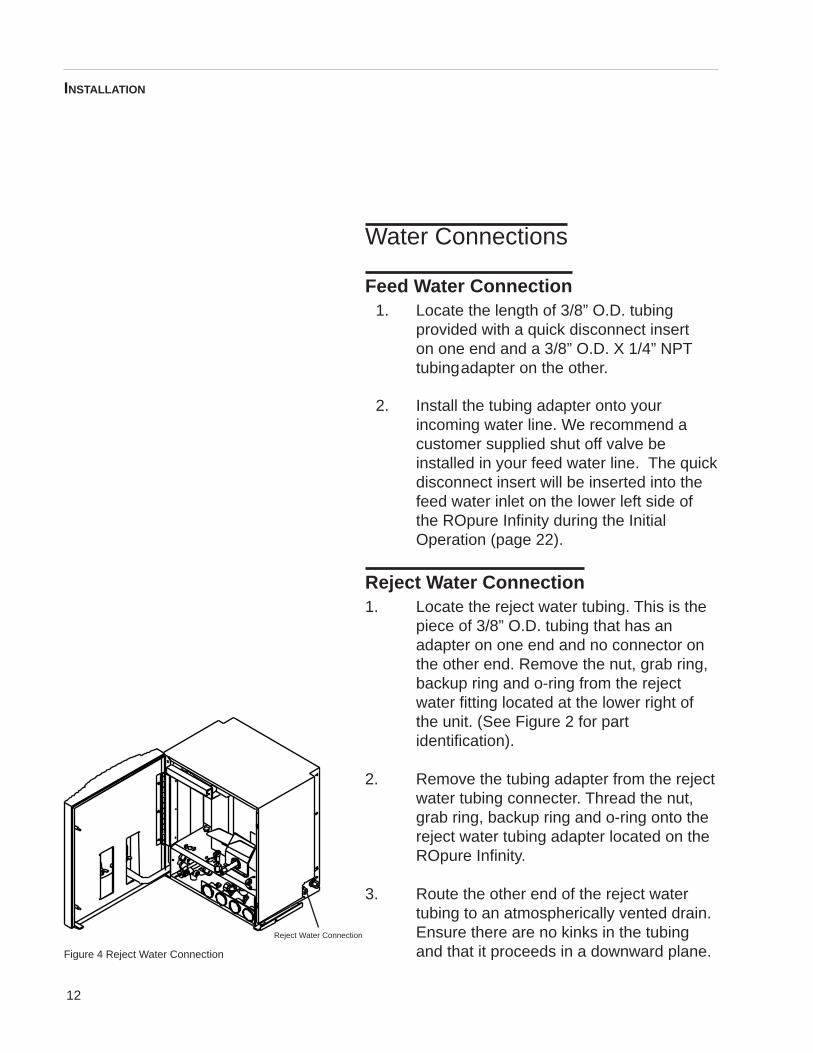
Reject Water Connection1. Locate the reject water tubing. This is the
piece of 3/8” O.D. tubing that has anadapter on one end and no connector onthe other end. Remove the nut, grab ring,backup ring and o-ring from the rejectwater fitting located at the lower right ofthe unit. (See Figure 2 for partidentification).
2. Remove the tubing adapter from the rejectwater tubing connecter. Thread the nut,grab ring, backup ring and o-ring onto thereject water tubing adapter located on theROpure Infinity.
3. Route the other end of the reject watertubing to an atmospherically vented drain.Ensure there are no kinks in the tubingand that it proceeds in a downward plane.
INSTALLATION
Figure 4 Reject Water Connection
Reject Water Connection
13
Product Water Connection to D9021
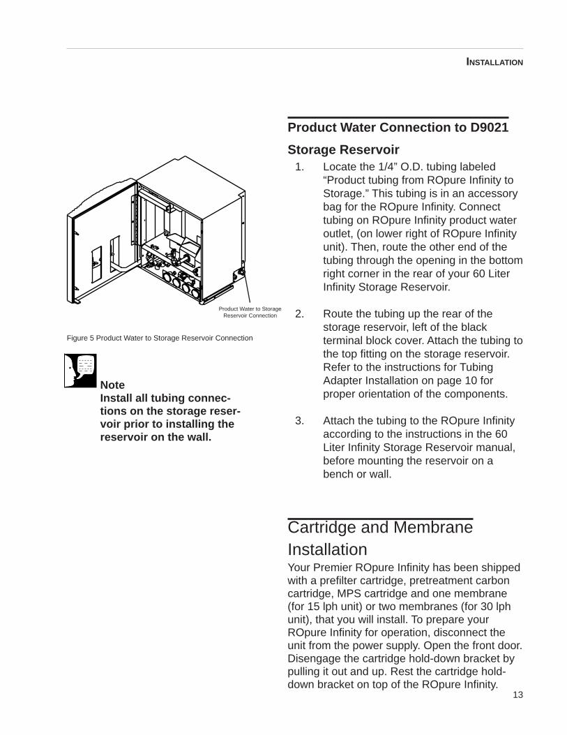
Storage Reservoir1. Locate the 1/4” O.D. tubing labeled
“Product tubing from ROpure Infinity toStorage.” This tubing is in an accessorybag for the ROpure Infinity. Connecttubing on ROpure Infinity product wateroutlet, (on lower right of ROpure Infinityunit). Then, route the other end of thetubing through the opening in the bottomright corner in the rear of your 60 LiterInfinity Storage Reservoir.
2. Route the tubing up the rear of thestorage reservoir, left of the blackterminal block cover. Attach the tubing tothe top fitting on the storage reservoir.Refer to the instructions for TubingAdapter Installation on page 10 forproper orientation of the components.
3. Attach the tubing to the ROpure Infinityaccording to the instructions in the 60Liter Infinity Storage Reservoir manual,before mounting the reservoir on abench or wall.
Cartridge and MembraneInstallationYour Premier ROpure Infinity has been shippedwith a prefilter cartridge, pretreatment carboncartridge, MPS cartridge and one membrane(for 15 lph unit) or two membranes (for 30 lphunit), that you will install. To prepare yourROpure Infinity for operation, disconnect theunit from the power supply. Open the front door.Disengage the cartridge hold-down bracket bypulling it out and up. Rest the cartridge hold-down bracket on top of the ROpure Infinity.
INSTALLATION
Figure 5 Product Water to Storage Reservoir Connection
Product Water to StorageReservoir Connection
NoteInstall all tubing connec-tions on the storage reser-voir prior to installing thereservoir on the wall.
14
Prefilter InstallationParticulates can damage your membranes,resulting in premature membrane failure.Therefore, your ROpure Infinity uses a prefilter toremove particulates from your feed water.Install the prefilter as follows:
1. Remove a new prefilter (Part NumberD9004) from its plastic bag.
2. Wet the o-rings on both end caps of theprefilter.
3. Insert the upper end cap into the upperfarthest left position of the two cartridgeend cap sockets below the cartridgehold-down bracket until it bottoms out inthe connector. The upper end cap is theone with the right angle turn and theflange. The flange on the end cap slidesdown inside the keyway wall.
4. Lower the prefilter and insert the lowerend cap into the lower left socket until itis firmly seated.
Pretreatment Carbon Cartridge
InstallationChlorine can also damage your membranes,resulting in premature membrane failure.Therefore, your ROpure Infinity uses an extrudedcarbon cartridge to remove chlorine from yourfeed water.
INSTALLATION
NoteThe top cartridge nipple is theone with the right-angle turnand one flange. The bottomcartridge nipple extendsstraight out from the cartridge.
The flange on the top cartridgenipple should be able to slidedown the keyway wall behindthe sheet metal.
WarningDepressurize system prior todisengaging the cartridge hold-down bracket.
15
Install the carbon cartridge as follows:1. Remove a new carbon cartridge (Part
Number D9005) from its plastic bag.
2. Wet the o-rings on both end caps ofthe carbon cartridge.
3. Insert the upper end cap into theupper position immediately right of theprefilter until it bottoms out in theconnector. (The upper end cap is theone with the right angle turn and theflange.) The flange on the end capslides down inside the keyway wall.
4. Lower the carbon cartridge and insertthe lower end cap into the lowersocket immediately right of the prefilteruntil it is firmly seated.
5. With both the prefilter andpretreatment carbon cartridgesinstalled, place the cartridge hold-down bracket in the position that holdsthe cartridges in place.
MPS InstallationThe MPS is a customer-installed clear plasticbag containing organophosphate powder. Thepowder is combined with water and pumpedthrough the ROpure Infinity system to eliminatescale buildup on the membrane surface. Afterfeed water flows through the prefilter and
INSTALLATION
NoteThe top cartridge nipple is theone with the right-angle turn andone flange. The bottom cartridgenipple extends straight out fromthe cartridge.
The flange on the top cartridgenipple should be able to slidedown the keyway wall behind thesheet metal.
16
pretreatment carbon cartridge, a pump injects4-8 ppm of the powder-water mixture into thewater flowing through the unit before it reachesthe membrane (15 l/hr models) or membranes(30 l/hr models). The MPS is included on allpremier units and is optional on all basic units.
1. Remove the small, clear plastic bag(Part Number CM900X1) containingorganophosphate powder from thepacking materials.
2. Remove the lid on the bag, twisting itcounterclockwise. Add 1 liter ofdeionized, distilled or reverse osmosiswater and agitate. Reattach the lid,twisting it clockwise.
3. Locate the quick disconnect fitting forthe MPS. It will be protruding from ahole just to the right of where youinstalled the carbon cartridge andabove the second pressure gauge atthe bottom of the unit. Connect thetubing on the MPS bag for quick dis-connect.
4. Carefully place the bag upside down inthe MPS holder to the right of thecarbon cartridge, with the tubing-quickdisconnect connection fitting in the U-shaped opening, just above the holefor the quick disconnect.
Membrane Installation
15 LITER PER HOUR UNITS (1 MEMBRANE)
1. Remove the membrane from thepackaging and remove the nut, grab
INSTALLATION
17
ring, back-up ring and o-ring from thetop two connections on the membrane.See Figure 2 for part identification.
2. Place the membrane in the rear of thetwo large holes located on the shelf ofthe inside cabinet and secure in placewith the Velcro® strap located on thebracket attached to the right side wall ofthe ROpure Infinity. Ensure that thecenter connector (product) points to theleft and the offset (reject) connectorpoints toward the rear of the unit.
3. Locate the free tubing (not attached toanother piece of tubing) labeled“Product” and remove the tubingadapter ensuring that the o-ring, grabring and back-up ring remain with thenut and attach to the center adapter onthe membrane. The adapter can bediscarded.
4. Locate the other length of free tubing(not attached to another piece of tubing)labeled “Reject” and remove the tubingadapter ensuring that the o-ring, grabring and back-up ring remain with thenut and attach to the remaining adapteron the membrane. The adapter can bediscarded.
5. Below the shelf locate the small piece oftubing with the quick disconnectattached (comes from the pump) andattach to the mating quick disconnectincluded on the bottom of themembrane.
INSTALLATION
NoteThe attached product and rejecttubing located on the inside ofthe cabinet is used on systemsthat utilize 2 membranes.
18
30 LITER PER HOUR UNITS (2 MEMBRANES)
1. Remove the membranes from thepackaging and remove the nut, grabring, back-up ring and o-ring from thetop two connections on bothmembranes. See Figure 2 for partidentification.
2. Place the first membrane in the rear ofthe two large holes located on the shelfof the inside cabinet and secure it inplace with the Velcro strap located onthe bracket attached to the right sidewall of the ROpure Infinity. Ensure thatthe center connector (product) points tothe left and the offset (reject) connectorpoints toward the rear of the unit.
3. Locate the free tubing (not attached toanother piece of tubing) labeled“Product” and remove the tubingadapter ensuring that the o-ring, grabring and back-up ring remain with thenut and attach to the center adapter onthe membrane. The adapter can bediscarded.
4. Separate the product and reject tubingfrom the coupled tubing inside thecabinet and install the nut labeled“Reject” on the remaining adapter on therear membrane. Ensure that the nutincludes the o-ring, back-up ring andgrab ring prior to installing.
5. Place the second membrane in the fronthole of the two large holes located onthe shelf of the inside cabinet andsecure it in place with the Velcro straplocated on the bracket attached to theride side wall of the ROpure Infinity.
NoteThe larger piece of tubing withthe quick disconnect attached isused only on models that utilize 2membranes.
INSTALLATION
19
Ensure that the center connector (product)points to the left and the offset (reject)connector points toward the rear of theunit.
6. Attach the remaining product tubing (thatwas separated in Step 4) to the center ofthe second membrane. After removing thetubing adapter from the remaining rejectfitting, attach the nut labeled “reject” to theright tubing adapter of the frontmembrane. Again, ensure that the o-ring,back-up ring and grab ring remain with thenut prior to installing.
7. Below the shelf locate the small piece oftubing with the quick disconnect attached(comes from the pump) and attach to themating quick disconnect included on thebottom of the rear membrane.
8. Locate the larger piece of tubing with thequick disconnect and attach it to the frontmembrane.
INSTALLATION
20
Main Power SwitchThe main power switch on the ROpure Infinity islocated on the lower left side of the unit (as youface the front of the unit), directly above thepower cord receptacle. This switch should beturned off when any maintenance is to be doneon the unit.
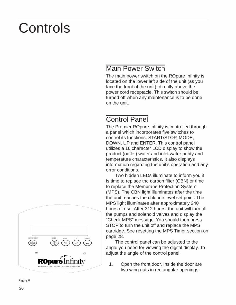
Control PanelThe Premier ROpure Infinity is controlled througha panel which incorporates five switches tocontrol its functions: START/STOP, MODE,DOWN, UP and ENTER. This control panelutilizes a 16 character LCD display to show theproduct (outlet) water and inlet water purity andtemperature characteristics. It also displaysinformation regarding the unit’s operation and anyerror conditions.
Two hidden LEDs illuminate to inform you itis time to replace the carbon filter (CBN) or timeto replace the Membrane Protection System(MPS). The CBN light illuminates after the timethe unit reaches the chlorine level set point. TheMPS light illuminates after approximately 240hours of use. After 312 hours, the unit will turn offthe pumps and solenoid valves and display the“Check MPS” message. You should then pressSTOP to turn the unit off and replace the MPScartridge. See resetting the MPS Timer section onpage 28.
The control panel can be adjusted to theangle you need for viewing the digital display. Toadjust the angle of the control panel:
1. Open the front door. Inside the door aretwo wing nuts in rectangular openings.
Controls
MPSCBN
START/STOP ENTERDOWN UPMODE
Figure 6
21
2. Turn the wing nuts counterclockwise tounlock and loosen them. The controlpanel will now pivot top to bottom in itsopening. Reposition the control panel toyour desired viewing position.
3. Lock the control panel in place byturning the wing nuts clockwise untilthey are hand-tightened.
SwitchesWhen the main power switch (on the lower leftside of the unit) is on, the five switches on thecontrol panel function as follows:
START/STOP puts the unit into run (on) modeor off mode.
MODE allows you to access the Mode Menu,which includes these displays: “MembraneFlush,” “Reset CBN Timer,” “Reset MPS Timer,”chlorine level in parts per million, “ChangeChlorine Level,” and “Display Menu.”
ENTER allows you to make a selection fromthe Mode Menu or to accept a new set point orchlorine level.
UP and DOWN allow you to scroll through theDisplay Menu or the Mode Menu. They alsocan be used to modify the set point andchlorine level.
CONTROLS
22
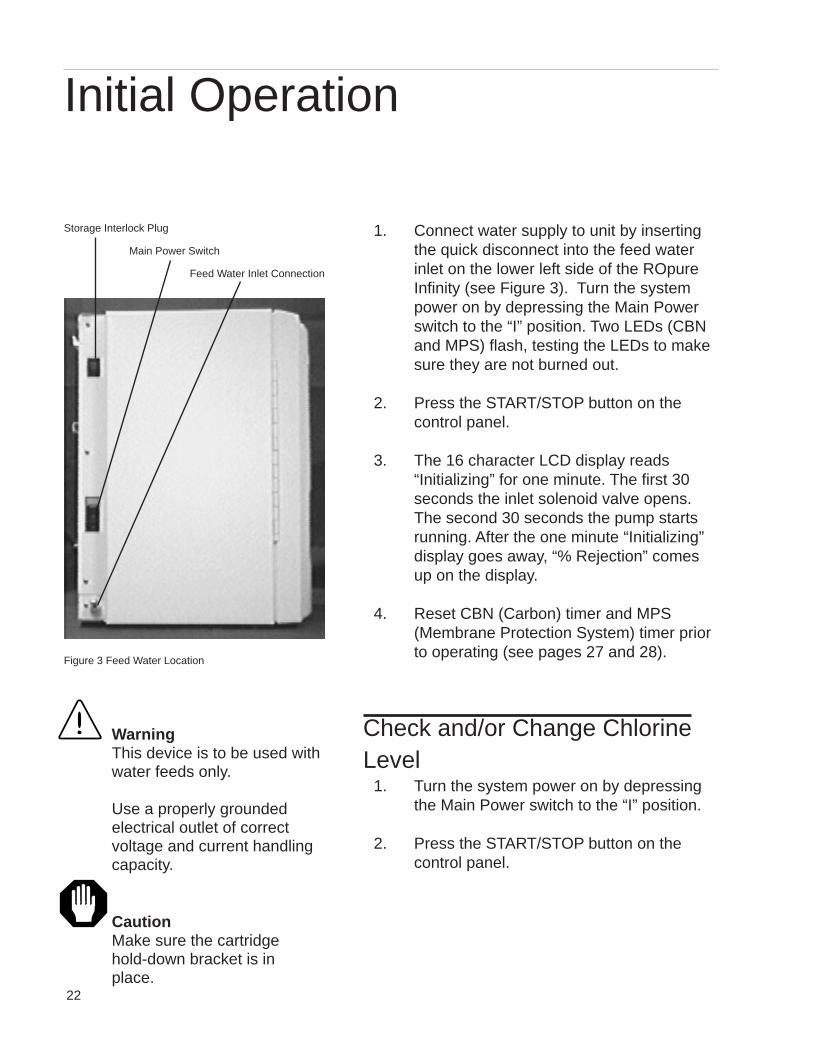
1. Connect water supply to unit by insertingthe quick disconnect into the feed waterinlet on the lower left side of the ROpureInfinity (see Figure 3). Turn the systempower on by depressing the Main Powerswitch to the “I” position. Two LEDs (CBNand MPS) flash, testing the LEDs to makesure they are not burned out.
2. Press the START/STOP button on thecontrol panel.
3. The 16 character LCD display reads“Initializing” for one minute. The first 30seconds the inlet solenoid valve opens.The second 30 seconds the pump startsrunning. After the one minute “Initializing”display goes away, “% Rejection” comesup on the display.
4. Reset CBN (Carbon) timer and MPS(Membrane Protection System) timer priorto operating (see pages 27 and 28).
Check and/or Change ChlorineLevel
1. Turn the system power on by depressingthe Main Power switch to the “I” position.
2. Press the START/STOP button on thecontrol panel.
WarningThis device is to be used withwater feeds only.
Use a properly groundedelectrical outlet of correctvoltage and current handlingcapacity.
CautionMake sure the cartridgehold-down bracket is inplace.
Initial Operation
Figure 3 Feed Water Location
Storage Interlock Plug
Main Power Switch
Feed Water Inlet Connection
23
3. Press the MODE button and DownArrow. Change Chlorine Level. Enter.
4. Press DOWN button until you see oneof three Chlorine level readings on thedisplay:
0.05-0.80 ppm (960 hours)0.81-1.40 ppm (480 hours)1.41-Max (336 hours)
5. To change the Chlorine level from whatyour display reads, press the DOWNswitch until it reads “Change Cl Level.”You will be placed in a short menu asfollows:
0.05-0.80 ppm (960 hours)0.81-1.40 ppm (480 hours)1.41-Max (336 hours)
6. You can scroll through this menu withthe UP and DOWN buttons and save anew setting by pressing the ENTERbutton.
7. If you decide not to change the setting,pressing the Mode button will return youto the top item in the Mode Menu, whichis “Membrane Flush.”
NotePressing STOP will cancel anyselection in the Mode Menu. Ifyou hit ENTER by mistake, pressMODE to start over in the ModeMenu.
NoteThe ROpure Infinity reminds youwhen it is time to change thecarbon cartridge. To properly setthe instrument, your incomingwater chlorine level must beprogrammed into the ROpureInfinity.
INITIAL OPERATION
24
Flushing the Membrane orMembranes
1. Turn the system power on by depressingthe Main Power switch to the “I” position.
2. Press the START/STOP button on thecontrol panel.
3. Press the MODE button. The display willread “Membrane Flush.”
4. To do a membrane flush, press the ENTERbutton. After you press ENTER, the displaywill read “Membrane Flush10” and thencount down a 10-minute membrane flushon the display.
5. The flush can be terminated at any time bypressing the stop button.
1. Turn the system power on by depressingthe Main Power switch to the “I” position.Two LEDs (CBN and MPS) flash, testingthe LEDs to make sure they are not
INITIAL OPERATION
NoteThe ROpure Infinity flushesautomatically in standby for 10minutes, after 3 hours, and 50minutes of inactivity (reservoirfull). This prevents stagnantwater from damaging the mem-brane. A flush can also be initi-ated manually.
25
burned out.
2. Press the START/STOP button on thecontrol panel.
3. The 16 character LCD display reads“Initializing” for one minute. The first 30seconds the inlet solenoid valve opens.The second 30 seconds the pump startsrunning. After the one minute“Initializing” display goes away, “%Rejection” comes up on the display.
Reading the Purity of ProductWater and Inlet Water
1. Turn the system power on bydepressing the Main Power switch tothe “I” position. Two LEDs (CBN andMPS) flash, testing the LEDs to makesure they are not burned out.
2. Press the START/STOP button on thecontrol panel.
3. The 16 character LCD display reads“Initializing” for one minute. The first 30seconds the inlet solenoid valve opens.The second 30 seconds the pump startsrunning. After the one minute“Initializing” display goes away,“% Rejection” comes up on the display.
4. Press the DOWN button to:A) Display the resistivity of product
waterB) Display the conductivity of product
Normal Operation
26
waterC) Display the Total Dissolved Solids of
product waterD) Display temperature of product waterE) Display resistivity of inlet waterF) Display conductivity of inlet waterG) Display Total Dissolved Solids of
inlet waterH) Display temperature of inlet waterI) Display % rejection
Mode MenuPressing the Mode button shows the top item inthe Mode Menu, “Membrane Flush.” Themembrane flush was described in the InitialOperation section of this manual. The UP andDOWN switches scroll in the Mode Menu toaccess the other five displays:
1. Reset CBN (Carbon) Timer2. Reset MPS (Membrane Protection
System) Timer3. Chlorine level in parts per million4. Change Cl (chlorine) Level5. Display Menu
The change chlorine level was described in theInitial Operation section of this manual. Thedisplay menu was described in “Reading thePurity of Product Water and Inlet Water,”immediately preceding this section.
NORMAL OPERATION
CautionMake sure the cartridgehold-down bracket is inplace.
CautionDo not allow the ROpureInfinity to operate unlesswater is available to the unit.
27
Resetting the Carbon TimerThe red CBN light on your control panelilluminates when it is time to replace the carbonfilter (CBN). The CBN light illuminates after theoperation time reaches the chlorine level setpoint.
1. Turn the system power on by depressingthe Main Power switch to the “I” position.Two LEDs (CBN and MPS) flash, testingthe LEDs to make sure they are notburned out.
2. Press the START/STOP button on thecontrol panel.
3. The 16 character LCD display reads“Initializing” for one minute. The first 30seconds the inlet solenoid valve opens.The second 30 seconds the pump startsrunning. After the one minute “Initializing”display goes away, “% Rejection” comesup on the display.
4. Press the MODE button. Press the DOWNswitch until the display reads “Reset CBNTimer.”
5. Press ENTER twice to reset the carbontimer.
NORMAL OPERATION
NotePress STOP to cancel aselection in the Mode Menu.If you press ENTER bymistake, press MODE tostart over.
28
Resetting the MPS TimerThe red MPS light on your control panelilluminates when it is time to replace theMembrane Protection System (MPS). The MPSlight illuminates after approximately 240 hours ofuse. After 312 hours, the unit will turn off thepumps and solenoid valves and display the“Check MPS” message.
1. Turn the system power on by depressingthe Main Power switch to the “I” position.Two LEDs (CBN and MPS) flash, testingthe LEDs to make sure they are notburned out.
2. Press the START/STOP button on thecontrol panel.
3. The 16 character LCD display reads“Initializing” for one minute. The first 30seconds the inlet solenoid valve opens.The second 30 seconds the pump startsrunning. After the one minute “Initializing”display goes away, “% Rejection” comesup on the display.
4. Press the MODE button. Press the DOWNbutton until the display reads “Reset MPSTimer.”
5. Press ENTER twice to reset the MPStimer.
NORMAL OPERATION
NoteWhen the “Check MPS”message appears, pressSTOP to turn the unit off andreplace the MPS plasticbottle. When you power upthe unit and press STARTthe “Check MPS” messagewill still be on the display.Pressing the MODE buttonbrings up the “Reset MPSTimer” display. PressingENTER twice will reset thetime and LED and resumenormal operation.
29
Pressure GaugesThere are 4 pressure gauges on the ROpureInfinity. The functions of the gauges are toprovide you the necessary information as towhen certain maintenance procedures shouldbe accomplished. The pressure gauges arelocated in the inside of the front door, on thebottom of the cabinet. The 4 gauge functionsare as follows:
1. Prefilter Inlet— Provides you withincoming water pressure and is used inconjunction with the pre-filter outletgauge to determine when it is time tochange the prefilter.
2. Prefilter Outlet —Provides the pressurereading of the water exiting the prefilter.If there is a 10 psig pressure differentialbetween this reading and the prefilterinlet reading, the prefilter should bereplaced.
3. Carbon Outlet —Provides the pressurereading of the water exiting the carboncartridge. If there is a 10 psig pressuredifferential between this reading and theprefilter outlet reading, the carboncartridge should be replaced.
4. Membrane Pressure —Provides areading of the membrane pressure. Thegauge should read 60 psig, +/- 5 psig,during operation.
NORMAL OPERATION
30
Standby Mode
The display will read “Standby Mode” when thestorage tank is full. The unit is idle for 3 hours 50minutes during the “Standby Mode,” thenperforms a 10-minute membrane flush. Thedisplay will read “Membrane Flush10” during themembrane flush and count down the minutes onthe display. When the water level reaches the topfloat of the 60 Liter Infinity Storage Reservoir, theROpure Infinity unit goes into standby. When thewater level falls below the middle float in thereservoir, the ROpure Infinity resumes normalautomatic operation.
Selecting the Percent RejectionSet PointThe ROpure Infinity electronics include a user-programmable set point which indicates when thewater quality falls below the desired quality. Thedisplay reads “Below Setpoint” when the percentrejection of the product water is below yourdefined set point. The Set Point Mode allows youto change the setting for the minimum allowablepercent rejection by scrolling through thenumbers 0, 60, 70, 80, 90% with the UP orDOWN button.
The set point indication is set at the factory at70%.
You must start this procedure from the off (stop)position.
1. Press and hold the ENTER button.
2. Press the START button.
NoteDo not turn off the ROpureInfinity during non-workhours. Doing so will allowbacterial growth and othercontamination of the water inthe system. We recommendusing the Standby Mode.
NORMAL OPERATION
31
3. The display will read “Setpt. 70%”.
4. Release the ENTER and STARTbuttons.
5. To adjust the value, press the UP orDOWN arrow until your desired value isdisplayed and press ENTER.
The ENTER button saves the new value andreverts the ROpure Infinity back to the regularrun (on) mode. You may also follow the aboveprocedure to merely view the current set point.The ENTER button returns you to the run (on)mode. The STOP button turns the unit offwithout saving any changes to the set point thatmay have just been made (as long as ENTERhas not been pressed).
Low PressureThe display reads “Check Inlet” when the inletwater has low pressure. The ROpure Infinitywaits 1 minute and rechecks the pressure. After1 minute, if the pressure is still low the pumpwill stay off. You then need to check your inletwater line. See problem solving section page 40.
Error MessagesThere are three error displays you may seewhen there is a problem with your ROpureInfinity. They are:
“Error 1” — Trouble communicatingbetween meter and main processor.Restart unit by pressing the STOPswitch and turning Main Power Switch tothe“O” position. Then turn Main Power
NORMAL OPERATION
32
Switch to the “I” position and press theSTART button.
“Error 2” — The cell isn’t getting a goodreading of the water or it is disconnected.The display will go away by itself if the cellstarts reading properly. If not, you need torestart by pressing the STOP button andturning Main Power Switch to the“O” position. Then turn Main Power Switchto the “I” position and press the STARTbutton.
“Error 3” — The meter was resetimproperly. Restart unit by pressing theSTOP button and turning Main PowerSwitch to the “O” position. Then turn MainPower Switch to the “I” position and pressthe START button.
Other Status MessagesThere are three other messages you may see onthe display that either tell you the status of the unitor ask you to perform a function. They are:
“Enter to Reset” — This is a safety feature.You must press ENTER twice to reset theCBN or MPS timers.
“Membrane Flush” — This occurs after 3hours 50 minutes in standby.
“Check MPS” — This tells you the MPStime is passed 312 hours and it needs tobe replaced.
NORMAL OPERATION
33
Caring for Your ROpure InfinityWith proper care, your ROpure Infinity will giveyou consistently pure water. To ensure continuedgood service, regularly perform the followingprocedures
System SanitizationThe frequency of sanitizing depends on the rateand amount of contamination buildup.
The carbon cartridge must be removedbefore sanitization, the membranes can be left inplace.
The ROpure Infinity can be easily sanitizedby utilizing the sanitization cartridge (Part #50258).
To accomplish this, follow these step-by-stepinstructions.1. Turn off the ROpure Infinity. Turn off a
NANOpure or other equipment fed by theROpure Infinity and disconnect powerfrom the unit.
2. Disconnect the product water tubing to theROpure Infinity Reservoir and route todrain or other equipment.
3. Open the front door. Ensure all pressuregauges read “0”. Disengage the cartridgehold down bracket by pulling it out and up.Remove the right most cartridge, thecarbon cartridge, from the unit by pulling itup and out. Remove a D50258 sanitizationcartridge from its bag. Wet the cartridge o-ring with water. Install the D50258sanitization cartridge into the emptycartridge position. Press the top cartridgenipple into the upper socket until itbottoms out. Then, lower the cartridge,
WarningDisconnect from the powersupply prior to maintenanceand servicing.
Refer servicing to qualifiedpersonnel.
Ensure all pipingconnections are tight toavoid leakage of chemicals.
Ensure adequate ventilationwhen using chemicals forcleaning.
Follow carefully themanufacturers’ safetyinstructions on labels ofchemical containers andMaterial Safety Data Sheets(M.S.D.S.).
Maintenance
WarningDepressurize system prior todisengaging the cartridge hold-down bracket.
34
MAINTENANCE
inserting the bottom cartridge nipple intothe lower socket until it is firmly sealed.Replace the cartridge hold down bracket.All other cartridges and membranesshould be left in place. Close the frontdoor.
4. Reconnect power to the ROpure Infinity.Turn the main power switch to the “I” (on)position.
5. Push the start/stop button to start.6. Run water to drain for 10 minutes.7. After 10 minutes press the start/stop
button to turn the unit off. Turn the mainpower switch to “O” off position and allowthe chlorine to sit in the system for 20minutes.
8. Open the front door. Disengage thecartridge hold-down bracket.Depressurize the unit before removingcartridge, the prefilter and chlorine.Ensure all gauges read “0”. Removeboth cartridges by pulling first up andthen out. Throw away the cartridges.
9. Refer to Prefilter and Carbon CartridgeInstallation to install new cartridges.
10. Operate with all water being sent to drainfor 30 minutes.
11. Reconnect the product water tubing to theROpure Infinity reservoir.
12. Operate unit normally (see NormalOperation section).
General Cleaning InstructionsWipe exterior surfaces with lightly dampened
cloth containing mild soap solution.
35
Service and Repair
Normal Unit OperationBelow is a brief description of the normalautomatic operation of the ROpure Infinity. Ifthe unit does not operate as described below,refer to the troubleshooting guide.
When you turn system power on by press-ing the Main Power Switch, the following eventswill occur:
1. Two LEDs (CBN and MPS) flash, testingthe LEDs to make sure that they work.
2. Press the START/STOP button on thecontrol panel.
3. The 16 character LCD display reads“Initializing” for one minute.
4. The first 30 seconds the inlet solenoidvalve opens.
5. The second 30 seconds the pump startsrunning.
6. After the one minute “Initializing” displaygoes away, “% Rejection” comes up onthe display.
7. When used with a Barnstead 60 LiterInfinity reservoir, the ROpure Infinity willrun automatically. It will turn off whenthe reservoir is full. The system isdesigned to automatically turn on andoff when water is needed to fill the tankor when the tank is full.
36
SERVICE AND REPAIR
Mains Fuse Replacement1. Turn off the ROpure Infinity and
disconnect it from the power supply byremoving the power cord directly belowthe I/O switch. Locate the fuse drawerabove the power cord receptacle.
2. Pull out the fuse drawer located in thepower entry module.
3. Remove old fuses and replace withfuses of the same type and rating. (SeeParts Listing.)
4. Replace fuse drawer.5. Reattach the power cord and
reconnect the unit to the power supply.6. Operate normally.
Transformer Fuse Replacement1. Turn off the ROpure Infinity and
disconnect it from the power supply byremoving the power cord directly belowthe I/O switch.
2. Ensure pressure gauges read “0” priorto proceeding.
3. Remove the 11 screws that hold theInfinity unit’s outer case in place. As youface the unit, there are three screws in theleft side near the back, three in the rightside near the back and five in the front,two on each side and one above thecartridge hold-down bracket. Remove thepressure switch connector from the upperleft side of the unit, if present.
4. Lift and remove the outer case.5. Remove the electric section cover directly
behind the two farthest left cartridges asthe Infinity unit faces you.
6. Locate the transformer fuse.
WarningTo avoid electrical shock, al-ways:
1. Use a properly groundedelectrical outlet of correctvoltage and current handlingcapacity.
2. Do not locate the ROpureInfinity directly over equipmentthat requires electrical service.Routine maintenance of thisunit may involve water spillageand subsequent electricalshock hazard if improperlylocated.
3. Replace fuses with those ofthe same type and rating.
4. Disconnect from the powersupply prior to maintenanceand servicing.
37
SERVICE AND REPAIR
7. Remove the old fuse and replace with afuse of the same type and rating. (SeeReplacement Parts list.)
8. Replace electric section cover.9. Reinstall the ROpure Infinity outer case.
Close the front door.10. Operate normally.
Membrane ReplacementA variety of factors will determine the servicelife of the ROpure Infinity membrane(s). Withproper maintenance and monitoring the mem-brane should last a minimum of 2 years. Toreplace the membrane, ensure that the powerand water are disconnected from the unit.
1. Remove the old membrane(s) bydisconnecting the reject and producttubing from the top of the membraneand the feed water connection from thebottom. Ensure that you note whichtubing is used for the frontmembrane and rear membrane if youare replacing two membranes.
2. Install the new membrane(s) byfollowing the “Membrane Installation”section of this manual.
Prefilter ReplacementThe prefilter incorporated in your ROpureInfinity is designed to remove particles fromyour incoming water source. It is impossible topredict expected life. It is recommended thatthe prefilter be replaced when the pressuredifferential across the prefilter reaches 10 psigpressure. The pressure is displayed on thepressure gauges located on the inside of theROpure Infinity cabinet. The differential repre-
WarningDepressurize system prior todisengaging the cartridge hold-down bracket.
38
sents the difference between the prefilter inlet andthe prefilter outlet. To replace the prefilter, ensurethat all power and water are disconnected fromthe unit.
1. Remove the prefilter by first disconnectingthe cartridge hold down bracket.
2. Remove the prefilter by pulling the prefilterup and then out.
3. Replace the prefilter by following theinstructions located in the “PrefilterInstallation” section of this manual.
Carbon ReplacementThe carbon pretreatment cartridge incorporatedprovides a combination pre-filtration and chlorineremoval. There is a timer built into the ROpureInfinity which will alert you when the carbonrequires replacement. This is addressed in the“Check and/or Change Chlorine” section of thismanual. When the “CBN” light illuminates thecarbon cartridge must be replaced. To replace thecarbon cartridge, ensure that all power and waterare disconnected from the unit.
1. Remove the carbon cartridge by firstdiconnecting the cartridge hold downbracket.
2. Remove the carbon cartridge by pullingthe prefilter up and then out.
3. Replace the carbon cartridge by followingthe instructions located in the“Pretreatment Carbon CartridgeInstallation” section of this manual.
4. Reset the “CBN” timer by following the“Resetting the Carbon Timer” sectionincluded in this manual.
SERVICE AND REPAIR
WarningDepressurize system prior todisengaging the cartridge hold-down bracket.
39
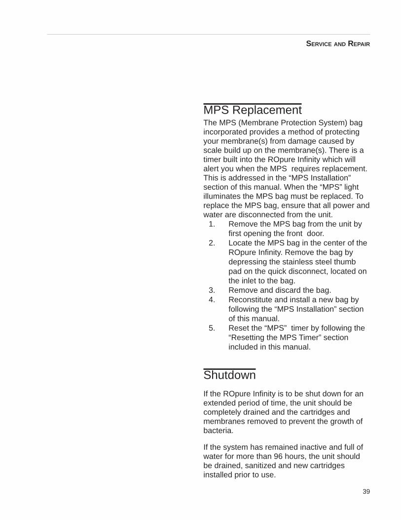
MPS ReplacementThe MPS (Membrane Protection System) bagincorporated provides a method of protectingyour membrane(s) from damage caused byscale build up on the membrane(s). There is atimer built into the ROpure Infinity which willalert you when the MPS requires replacement.This is addressed in the “MPS Installation”section of this manual. When the “MPS” lightilluminates the MPS bag must be replaced. Toreplace the MPS bag, ensure that all power andwater are disconnected from the unit.
1. Remove the MPS bag from the unit byfirst opening the front door.
2. Locate the MPS bag in the center of theROpure Infinity. Remove the bag bydepressing the stainless steel thumbpad on the quick disconnect, located onthe inlet to the bag.
3. Remove and discard the bag.4. Reconstitute and install a new bag by
following the “MPS Installation” sectionof this manual.
5. Reset the “MPS” timer by following the“Resetting the MPS Timer” sectionincluded in this manual.
Shutdown
If the ROpure Infinity is to be shut down for anextended period of time, the unit should becompletely drained and the cartridges andmembranes removed to prevent the growth ofbacteria.
If the system has remained inactive and full ofwater for more than 96 hours, the unit shouldbe drained, sanitized and new cartridgesinstalled prior to use.
SERVICE AND REPAIR
40
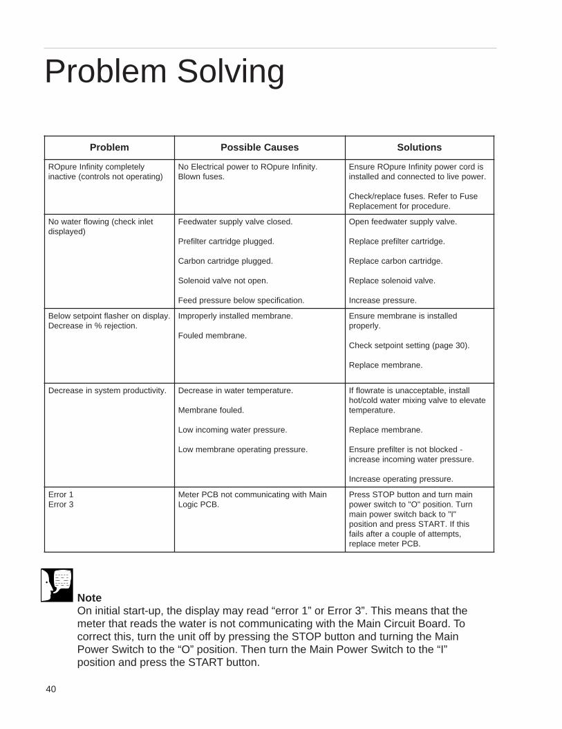
Problem Solving
NoteOn initial start-up, the display may read “error 1” or Error 3”. This means that themeter that reads the water is not communicating with the Main Circuit Board. Tocorrect this, turn the unit off by pressing the STOP button and turning the MainPower Switch to the “O” position. Then turn the Main Power Switch to the “I”position and press the START button.
melborP sesuaCelbissoP snoituloS
yletelpmocytinifnIerupOR)gnitarepotonslortnoc(evitcani
.ytinifnIerupORotrewoplacirtcelEoN.sesufnwolB
sidrocrewopytinifnIerupORerusnE.rewopevilotdetcennocdnadellatsni
esuFotrefeR.sesufecalper/kcehC.erudecorproftnemecalpeR
telnikcehc(gniwolfretawoN)deyalpsid
.desolcevlavylppusretawdeeF
.deggulpegdirtracretliferP
.deggulpegdirtracnobraC
.nepotonevlavdioneloS
.noitacificepswoleberusserpdeeF
.evlavylppusretawdeefnepO
.egdirtracretliferpecalpeR
.egdirtracnobracecalpeR
.evlavdionelosecalpeR
.erusserpesaercnI
.yalpsidnorehsalftniopteswoleB.noitcejer%niesaerceD
.enarbmemdellatsniylreporpmI
.enarbmemdeluoF
dellatsnisienarbmemerusnE.ylreporp
.)03egap(gnittestniopteskcehC
.enarbmemecalpeR
.ytivitcudorpmetsysniesaerceD .erutarepmetretawniesaerceD
.deluofenarbmeM
.erusserpretawgnimocniwoL
.erusserpgnitarepoenarbmemwoL
llatsni,elbatpeccanusietarwolffIetaveleotevlavgniximretawdloc/toh
.erutarepmet
.enarbmemecalpeR
-dekcolbtonsiretliferperusnE.erusserpretawgnimocniesaercni
.erusserpgnitarepoesaercnI
1rorrE3rorrE
niaMhtiwgnitacinummoctonBCPreteM.BCPcigoL
niamnrutdnanottubPOTSsserPnruT.noitisop"O"othctiwsrewop
"I"otkcabhctiwsrewopniamsihtfI.TRATSsserpdnanoitisop
,stpmettafoelpuocaretfasliaf.BCPretemecalper
41
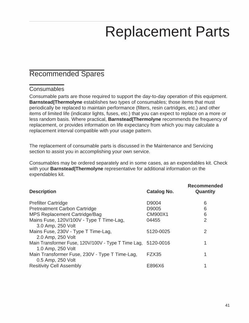
Recommended Spares
ConsumablesConsumable parts are those required to support the day-to-day operation of this equipment.Barnstead|Thermolyne establishes two types of consumables; those items that mustperiodically be replaced to maintain performance (filters, resin cartridges, etc.) and otheritems of limited life (indicator lights, fuses, etc.) that you can expect to replace on a more orless random basis. Where practical, Barnstead|Thermolyne recommends the frequency ofreplacement, or provides information on life expectancy from which you may calculate areplacement interval compatible with your usage pattern.
The replacement of consumable parts is discussed in the Maintenance and Servicingsection to assist you in accomplishing your own service.
Consumables may be ordered separately and in some cases, as an expendables kit. Checkwith your Barnstead|Thermolyne representative for additional information on theexpendables kit.
RecommendedDescription Catalog No. Quantity
Prefilter Cartridge D9004 6Pretreatment Carbon Cartridge D9005 6MPS Replacement Cartridge/Bag CM900X1 6Mains Fuse, 120V/100V - Type T Time-Lag, 04455 2
3.0 Amp, 250 VoltMains Fuse, 230V - Type T Time-Lag, 5120-0025 2
2.0 Amp, 250 VoltMain Transformer Fuse, 120V/100V - Type T Time Lag, 5120-0016 1
1.0 Amp, 250 VoltMain Transformer Fuse, 230V - Type T Time-Lag, FZX35 1
0.5 Amp, 250 VoltResitivity Cell Assembly E896X6 1
Replacement Parts
42
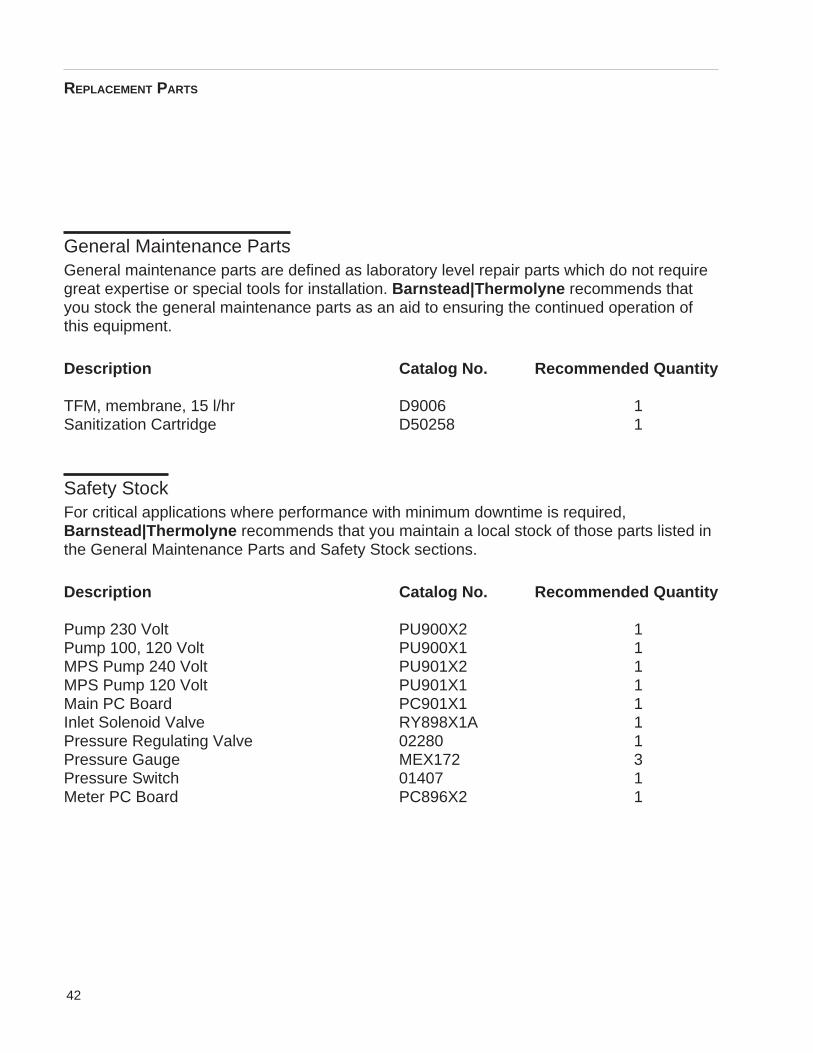
General Maintenance PartsGeneral maintenance parts are defined as laboratory level repair parts which do not requiregreat expertise or special tools for installation. Barnstead|Thermolyne recommends thatyou stock the general maintenance parts as an aid to ensuring the continued operation ofthis equipment.
Description Catalog No. Recommended Quantity
TFM, membrane, 15 l/hr D9006 1Sanitization Cartridge D50258 1
Safety StockFor critical applications where performance with minimum downtime is required,Barnstead|Thermolyne recommends that you maintain a local stock of those parts listed inthe General Maintenance Parts and Safety Stock sections.
Description Catalog No. Recommended Quantity
Pump 230 Volt PU900X2 1Pump 100, 120 Volt PU900X1 1MPS Pump 240 Volt PU901X2 1MPS Pump 120 Volt PU901X1 1Main PC Board PC901X1 1Inlet Solenoid Valve RY898X1A 1Pressure Regulating Valve 02280 1Pressure Gauge MEX172 3Pressure Switch 01407 1Meter PC Board PC896X2 1
REPLACEMENT PARTS
43
Flow Diagram
Feedwater Inlet
1 Pressure reducing valve
2 Inlet solenoid
4
Inlet R25 cell
5
Pressure gauge
6
Prefilter
10 MPS
11 Pump, injection
12 Main pump
13 Pressure gauge
7
Pressure gauge
Prefilter/Carbon
8 Pressure gauge
Flow Schematic ROpure Infinity Premier
3
R25
9 Pressure switch
14 Membrane #1
R25
1 3 4
2
56
78
9
10
12
13
14
Feedwater Inlet
Reject
Product
Product
Storage
16 15
11
15 Product R25 cell
16 Membrane #2
Restrictor17
17
Reject Outlet
44
Operating Log
laitinIpU-tratS
dnaetaDemiT
retaWdeeFytivitsiseR
retaWdeeFerutarepmeT
retaWdeeFMPP
retaWtcudorPytivitsiseR
retaWtcudorPetarwolF
retaWtcudorPMPP
retaWtcejeRetarwolF
tnecrePnoitcejeR
retliferPerusserPtelnI
retliferPerusserPteltuO
nobraCerusserPteltuO
enarbmeMerusserP
45
Please refer to the Specification Plate for thecomplete model number, serial number, andseries number when requesting service,replacement parts or in any correspondenceconcerning this unit.
All parts listed herein may be ordered fromthe Barnstead|Thermolyne dealer from whomyou purchased this unit or can be obtainedpromptly from the factory. When service orreplacement parts are needed we ask that youcheck first with your dealer. If the dealer cannothandle your request, then contact our CustomerService Department at 319-556-2241 or 800-553-0039.
Prior to returning any materials toBarnstead|Thermolyne Corp ., please contactour Customer Service Department for a “ReturnGoods Authorization” number (RGA). Materialreturned without a RGA number will be refused.
Ordering Procedures

46

47
One Year Limited Warranty
Barnstead|Thermolyne Corporation warrants that if a product manufactured byBarnstead|Thermolyne and sold within the continental United States or Canada proves tobe defective in material or construction, Barnstead|Thermolyne will provide you, withoutcharge, for a period of ninety (90) days, the labor, and a period of one (1) year, the parts,necessary to remedy any such defect. Outside the continental United States and Canada,the warranty provides, for one (1) year, the parts necessary to remedy any such defect. Thewarranty period shall commence either six (6) months following the date the product is soldby Barnstead|Thermolyne or on the date it is purchased by the original retail consumer,whichever date occurs first.
All warranty inspections and repairs must be performed by and parts obtained froman authorized Barnstead|Thermolyne dealer or Barnstead|Thermolyne (at its owndiscretion). Heating elements, however, because of their susceptibility to overheating andcontamination, must be returned to our factory, and if, upon inspection, it is concluded thatfailure is not due to excessive high temperature or contamination, warranty replacement willbe provided by Barnstead|Thermolyne . The name of the authorizedBarnstead|Thermolyne dealer nearest you may be obtained by calling 1-800-446-6060 orwriting to:
Barnstead|ThermolyneP.O. Box 797
2555 Kerper BoulevardDubuque, IA 52004-0797
USAFAX: (319) 589-0516
E-Mail: [email protected]|Thermolyne’s sole obligation with respect to its product shall be to repair
or replace the product. Under no circumstances shall it be liable for incidental orconsequential damage.
THE WARRANTY STATED HEREIN IS THE SOLE WARRANTY APPLICABLE TOBarnstead|Thermolyne PRODUCTS. Barnstead|Thermolyne EXPRESSLY DISCLAIMSANY AND ALL OTHER WARRANTIES, EXPRESSED OR IMPLIED, INCLUDINGWARRANTIES OF MERCHANTABILITY OR FITNESS FOR USE.

48
Barnstead Thermolyne2555 Kerper Blvd.P.O. Box 797Dubuque, IA 52004-0797 USAPHONE: 319-556-2241 • 800-553-0039FAX: 319-589-0516E-Mail: [email protected]
a subsidiary of