Embed Size (px)
Citation preview
www.howden.com
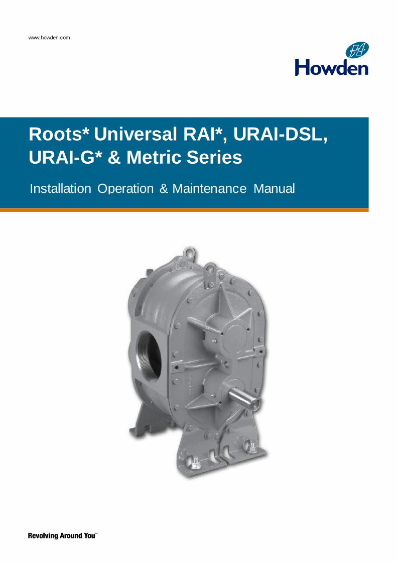
Roots* Universal RAI*, URAI-DSL,
URAI-G* & Metric Series
Installation Operation & Maintenance Manual

Page 2 of 28
Contents
Information Summary..............................................2
Safety Precautions..................................................3
Operating Limit........................................................3
Installation............................................................4-6
Technical Supplement for URAI-G blowers ............8
Lubrication............................................................8-9
Operation...............................................................10
Troubleshooting.....................................................11
Inspection & Maintenance.....................................12
Figures.............................................................13-16
Tables...............................................................16-17
Assembly Drawings..........................................18-23
Parts List.........................................................24-25
Basic Connection & Drive Shaft Information...26-28
Do these things to get the most from your RootsTM
Blower
Check shipment for damage. If found, file claim
with carrier and notify Howden Roots.
Unpack shipment carefully, and check contents
against Packing List. Notify Howden Roots if a
shortage appears.
Store in a clean, dry location until ready for
installation. Lift by methods discussed under
INSTALLATION to avoid straining or distorting
the equipment. Keep covers on all openings.
Protect against weather and corrosion if outdoor
storage is necessary.
Read OPERATING LIMITATIONS and
INSTALLATION sections in this manual and
plan the complete installation.
Provide for adequate safeguards against
accidents to persons working on or near the
equipment during both installation and
operation. See SAFETY PRECAUTIONS.
Install all equipment correctly. Foundation
design must be adequate and piping carefully
done. Use recommended accessories for
operating protection.
Make sure both driving and driven
equipment is correctly lubricated before
start-up. See LUBRICATION.
Read starting check points under OPERATION.
Run equipment briefly to check for installation errors
and make corrections. Follow with a trial run under
normal operating conditions.
In event of trouble during installation or operation,
do not attempt repairs of Howden Roots furnished
equipment. Notify Howden Roots, giving all
nameplate information plus an outline of operating
conditions and a description of the trouble.
Unauthorized attempts at equipment repair may
void Howden Roots warranty.
Units out of warranty may be repaired or adjusted
by the owner. Good inspection and maintenance
practices should reduce the need for repairs.
NOTE: Information in this manual is correct as of
the date of publication. Howden Roots reserves the
right to make design or material changes without
notice, and without obligation to make similar
changes on equipment of prior manufacture.
Roots products are sold subject to the current General Terms of Sale, ES104 and Warranty Policy WP-5020. Copies are available upon request.

Page 3 of 28
Safety Precautions
It is important that all personnel observe safety
precautions to minimize the chances of injury. Among
many considerations, the following should be particularly
noted:
Blower casing and associated piping or accessories may
become hot enough to cause major skin burns on
contact.
Internal and external rotating parts of the blower and
driving equipment can produce serious physical injuries.
Do not reach into any opening in the blower while it is
operating, or while subject to accidental starting. Protect
external moving parts with adequate guards.
Disconnect power before doing any work, and avoid
bypassing or rendering inoperative any safety or
protective devices.
If blower is operated with piping disconnected, place a
strong coarse screen over the inlet and avoid standing in
the discharge air stream.
CAUTION: Never cover the blower inlet with your
hand or other part of body.
Stay clear of the blast from pressure relief valves and
the suction area of vacuum relief valves.
Use proper care and good procedures in handling,
lifting, installing, operating and maintaining the
equipment.
Casing pressure must not exceed 25 PSI (1725 mbar)
gauge. Do not pressurize vented cavities from an
external source, nor restrict the vents without first
consulting Roots.
Do not use air blowers on explosive or hazardous
gases.
Other potential hazards to safety may also be
associated with operation of this equipment. All
personnel working in or passing through the area should
be trained to exercise adequate general safety
precautions.
Operating Limitations
A Roots blower or exhauster must be operated within
certain approved limiting conditions to enable continued
satisfactory performance. Warranty is contingent on
such operation.
Maximum limits for pressure, temperature and speed
are specified in Table 1 for various models & sizes of
blowers and exhausters. These limits apply to all units of
normal construction, when operated under standard
atmospheric conditions. Be sure to arrange connections
or taps for instruments, thermometers and pressure or
vacuum gauges at or near the inlet and discharge
connections of the unit. These, along with a tachometer,
will enable periodic checks of operating conditions.
PRESSURE – The pressure rise, between inlet and
discharge, must not exceed the figure listed for the
specific unit frame size concerned. Also, in any system
where the unit inlet is at a positive pressure above
atmosphere a maximum case rating of 25 PSI gauge
(1725 mbar) should not be exceeded without first
consulting Roots. Never should the maximum allowable
differential pressure be exceeded.
On vacuum service, with the discharge to atmospheric
pressure, the inlet suction or vacuum must not be
greater than values listed for the specific frame size.
TEMPERATURE – Blower & exhauster frame sizes are
approved only for installations where the following
temperature limitations can be maintained in service:
Measured temperature rise must not exceed listed
values when the inlet is at ambient temperature.
Ambient is considered as the general temperature of the
space around the unit. This is not outdoor temperature
unless the unit is installed outdoors.
If inlet temperature is higher than ambient, the listed
allowable temperature rise values must be reduced by
2/3 of the difference between the actual measured inlet
temperature and the ambient temperature.
The average of the inlet and discharge temperature
must not exceed 250°F. (121°C).
The ambient temperature of the space the blower/motor
is installed in should not be higher than 120°F (48.8°C).
SPEED – These blowers & exhausters may be operated
at speeds up to the maximum listed for the various
frame sizes. They may be direct coupled to suitable
constant speed drivers if pressure/temperature
conditions are also within limits. At low speeds,
excessive temperature rise may be a limiting factor
Special Note: The listed maximum allowable
temperature rise for any particular blower & exhauster
may occur well before its maximum pressure or vacuum
rating is reached. This may occur at high altitude, low
vacuum or at very low speed. The units’ operating limit
is always determined by the maximum rating reached
first. It can be any one of the three: Pressure,
Temperature or Speed.

Page 4 of 28
Installation
Roots blowers & exhausters are treated after factory
assembly to protect against normal atmospheric
corrosion. The maximum period of internal protection is
considered to be one year under average conditions, if
shipping plugs and seals are not removed. Protection
against chemical or salt water atmosphere is not
provided. Avoid opening the unit until ready to start
installation, as corrosion protection will be quickly lost
due to evaporation.
If there is to be an extended period between installation
and start up, the following steps should be taken to
ensure corrosion protection.
Coat internals of cylinder, gearbox and drive end
bearing reservoir with Nox-Rust VCI-10 or equivalent.
Repeat once a year or as conditions may require. Nox-
Rust VCI-10 is petroleum soluble and does not have to
be removed before lubricating. It may be obtained from
Daubert Chemical Co., 2000 Spring Rd., Oak Brook, Ill.
60521.
Paint shaft extension, inlet and discharge flanges, and
all other exposed surfaces with Nox-Rust X-110 or
equivalent.
Seal inlet, discharge, and vent openings. It is not
recommended that the unit be set in place, piped to the
system, and allowed to remain idle for extended periods.
If any part is left open to the atmosphere, the Nox-Rust
VCI-10 vapor will escape and lose its effectiveness.
Protect units from excessive vibration during storage.
Rotate shaft three or four revolutions every two weeks.
Prior to start up, remove flange covers on both inlet and
discharge and inspect internals to insure absence of
rust. Check all internal clearances. Also, at this time,
remove gearbox and drive end bearing cover and
inspect gear teeth and bearings for rust.
Because of the completely enclosed unit design,
location of the installation is generally not a critical
matter. A clean, dry and protected indoor location is
preferred. However, an outdoor location will normally
give satisfactory service. Important requirements are
that the correct grade of lubricating oil be provided for
expected operating temperatures, and that the unit be
located so that routine checking and servicing can be
performed conveniently. Proper care in locating driver
and accessory equipment must also be considered.
Supervision of the installation by a Howden Roots
Service Engineer is not usually required for these units.
Workmen with experience in installing light to medium
weight machinery should be able to produce satisfactory
results. Handling of the equipment needs to be
accomplished with care, and in compliance with safe
practices. Unit mounting must be solid, without strain or
twist, and air piping must be clean, accurately aligned
and properly connected.
Bare-shaft Units: Two methods are used to handle
a unit without base. One is to use lifting lugs bolted into
the top of the unit headplates. Test them first for
tightness and fractures by tapping with a hammer. In
lifting, keep the direction of cable pull on these bolts as
nearly vertical as possible. If lifting lugs are not
available, lifting slings may be passed under the cylinder
adjacent to the headplates. Either method prevents
strain on the extended drive shaft.
Packaged Units: When the unit is furnished
mounted on a baseplate, with or without a driver, use of
lifting slings passing under the base flanges is required.
Arrange these slings so that no strains are placed on the
unit casing or mounting feet, or on any mounted
accessory equipment. DO NOT use the lifting lugs in the
top of the unit headplates.
Before starting the installation, remove plugs, covers or
seals from unit inlet and discharge connections and
inspect the interior completely for foreign material. If
cleaning is required, finish by washing the cylinder,
headplates and impeller thoroughly with an appropriate
solvent. Turn the drive shaft by hand to make sure that
the impellers turn freely at all points. Anti-rust compound
on the connection flanges and drive shaft extension may
also be removed at this time with the same solvent.
Cover the flanges until ready to connect piping.
Mounting
Care will pay dividends when arranging the unit
mounting. This is especially true when the unit is a
“bare-shaft” unit furnished without a baseplate. The
convenient procedure may be to mount such a unit
directly on a floor or small concrete pad, but this
generally produces the least satisfactory results. It
definitely causes the most problems in levelling and
alignment and may result in a “Soft Foot” condition.
Correct soft foot before operation to avoid unnecessary
loading on the casing and bearings. Direct use of
building structural framing members is not
recommended.
For blowers without a base, it is recommended that a
well anchored and carefully levelled steel or cast iron
mounting plate be provided. The plate should be at least
1 inch (25 mm) thick, with its top surface machined flat,
and large enough to provide levelling areas at one side
and one end after the unit is mounted. It should have
properly sized studs or tapped holes located to match
the unit foot drilling. Proper use of a high quality
machinist’s level is necessary for adequate installation.
Page 5 of 28
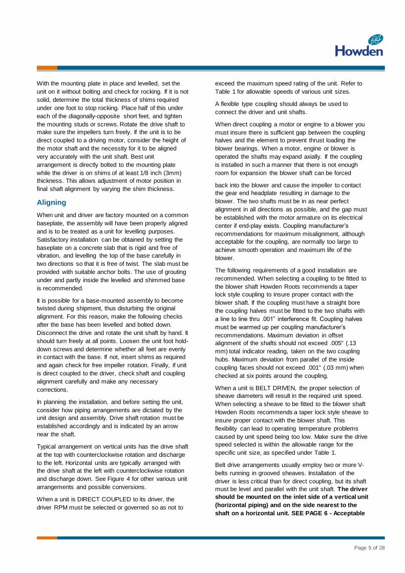
With the mounting plate in place and levelled, set the
unit on it without bolting and check for rocking. If it is not
solid, determine the total thickness of shims required
under one foot to stop rocking. Place half of this under
each of the diagonally-opposite short feet, and tighten
the mounting studs or screws. Rotate the drive shaft to
make sure the impellers turn freely. If the unit is to be
direct coupled to a driving motor, consider the height of
the motor shaft and the necessity for it to be aligned
very accurately with the unit shaft. Best unit
arrangement is directly bolted to the mounting plate
while the driver is on shims of at least 1/8 inch (3mm)
thickness. This allows adjustment of motor position in
final shaft alignment by varying the shim thickness.
Aligning
When unit and driver are factory mounted on a common
baseplate, the assembly will have been properly aligned
and is to be treated as a unit for levelling purposes.
Satisfactory installation can be obtained by setting the
baseplate on a concrete slab that is rigid and free of
vibration, and levelling the top of the base carefully in
two directions so that it is free of twist. The slab must be
provided with suitable anchor bolts. The use of grouting
under and partly inside the levelled and shimmed base
is recommended.
It is possible for a base-mounted assembly to become
twisted during shipment, thus disturbing the original
alignment. For this reason, make the following checks
after the base has been levelled and bolted down.
Disconnect the drive and rotate the unit shaft by hand. It
should turn freely at all points. Loosen the unit foot hold-
down screws and determine whether all feet are evenly
in contact with the base. If not, insert shims as required
and again check for free impeller rotation. Finally, if unit
is direct coupled to the driver, check shaft and coupling
alignment carefully and make any necessary
corrections.
In planning the installation, and before setting the unit,
consider how piping arrangements are dictated by the
unit design and assembly. Drive shaft rotation must be
established accordingly and is indicated by an arrow
near the shaft.
Typical arrangement on vertical units has the drive shaft
at the top with counterclockwise rotation and discharge
to the left. Horizontal units are typically arranged with
the drive shaft at the left with counterclockwise rotation
and discharge down. See Figure 4 for other various unit
arrangements and possible conversions.
When a unit is DIRECT COUPLED to its driver, the
driver RPM must be selected or governed so as not to
exceed the maximum speed rating of the unit. Refer to
Table 1 for allowable speeds of various unit sizes.
A flexible type coupling should always be used to
connect the driver and unit shafts.
When direct coupling a motor or engine to a blower you
must insure there is sufficient gap between the coupling
halves and the element to prevent thrust loading the
blower bearings. When a motor, engine or blower is
operated the shafts may expand axially. If the coupling
is installed in such a manner that there is not enough
room for expansion the blower shaft can be forced
back into the blower and cause the impeller to contact
the gear end headplate resulting in damage to the
blower. The two shafts must be in as near perfect
alignment in all directions as possible, and the gap must
be established with the motor armature on its electrical
center if end-play exists. Coupling manufacturer’s
recommendations for maximum misalignment, although
acceptable for the coupling, are normally too large to
achieve smooth operation and maximum life of the
blower.
The following requirements of a good installation are
recommended. When selecting a coupling to be fitted to
the blower shaft Howden Roots recommends a taper
lock style coupling to insure proper contact with the
blower shaft. If the coupling must have a straight bore
the coupling halves must be fitted to the two shafts with
a line to line thru .001” interference fit. Coupling halves
must be warmed up per coupling manufacturer’s
recommendations. Maximum deviation in offset
alignment of the shafts should not exceed .005" (.13
mm) total indicator reading, taken on the two coupling
hubs. Maximum deviation from parallel of the inside
coupling faces should not exceed .001" (.03 mm) when
checked at six points around the coupling.
When a unit is BELT DRIVEN, the proper selection of
sheave diameters will result in the required unit speed.
When selecting a sheave to be fitted to the blower shaft
Howden Roots recommends a taper lock style sheave to
insure proper contact with the blower shaft. This
flexibility can lead to operating temperature problems
caused by unit speed being too low. Make sure the drive
speed selected is within the allowable range for the
specific unit size, as specified under Table 1.
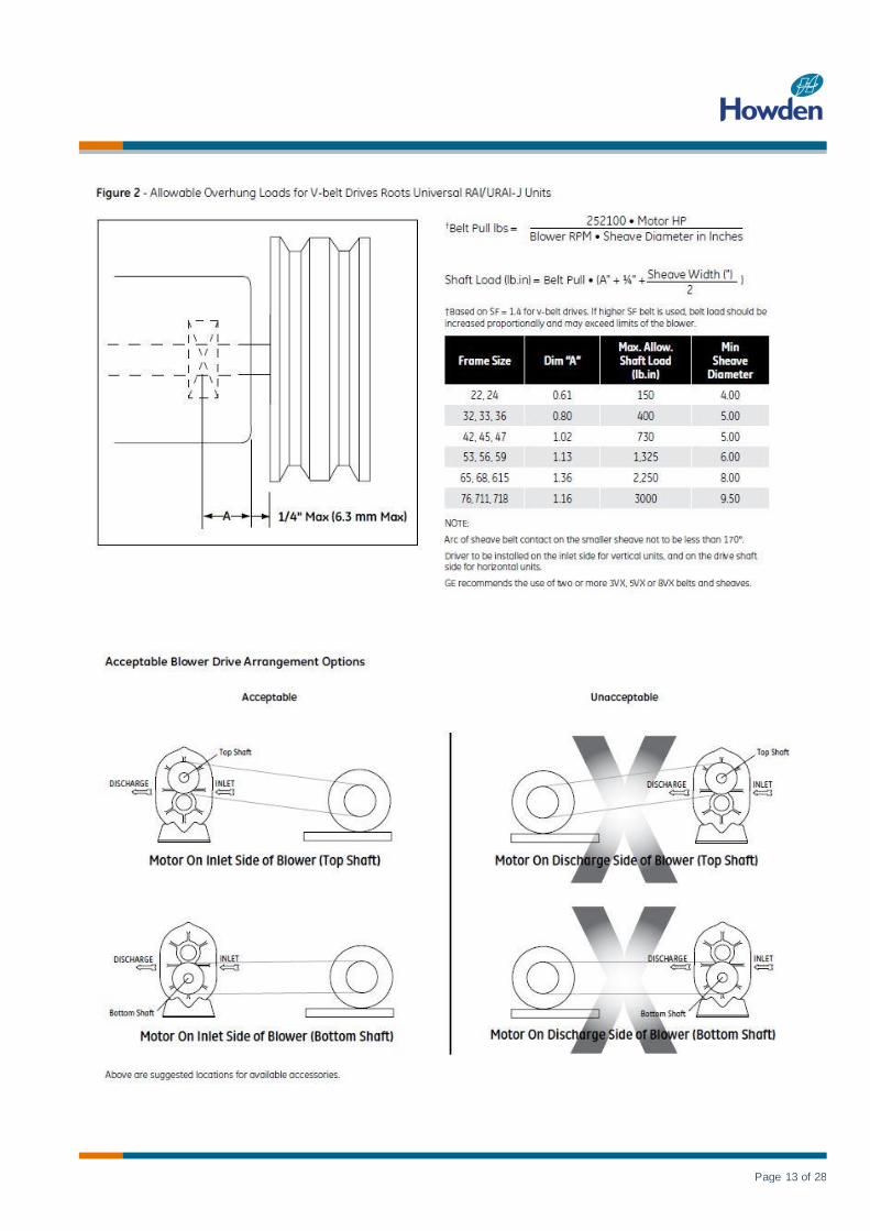
Belt drive arrangements usually employ two or more V-
belts running in grooved sheaves. Installation of the
driver is less critical than for direct coupling, but its shaft
must be level and parallel with the unit shaft. The driver
should be mounted on the inlet side of a vertical unit
(horizontal piping) and on the side nearest to the
shaft on a horizontal unit. SEE PAGE 6 - Acceptable

Page 6 of 28
Blower Drive Arrangement Options.
The driver must also be mounted on an adjustable base
to permit installing, adjusting and removing the V-belts.
To position the driver correctly, both sheaves need to be
mounted on their shafts and the nominal shaft center
distance known for the belt lengths to be used.
CAUTION: Drive couplings and sheaves (pulleys)
should have an interference fit to the shaft of the blower
(set screw types of attachment generally do not provide
reliable service.) It is recommended that the drive
coupling or sheave used have a taperlock style bushing
which is properly sized to provide the correct
interference fit required. Drive couplings, that require
heating to fit on the blower shaft, should be installed per
coupling manufacturer recommendations. A drive
coupling or sheave should not be forced on to the shaft
of the blower as this could affect internal clearances
resulting in damage to the blower.
Engine drive applications often require special
consideration to drive coupling selection to avoid
harmful torsional vibrations. These vibrations may
lead to blower damage if not dampened adequately.
It is often necessary to install a fly-wheel and/or a
torsionally soft elastic element coupling based on
the engine manufacturer recommendations.
The driver sheave should also be mounted as close to
its bearing as possible, and again should fit the shaft
correctly. Position the driver on its adjustable base so
that 2/3 of the total movement is available in the
direction away from the unit, and mount the assembly so
that the face of the sheave is accurately in line with
the unit sheave. This position minimizes belt wear, and
allows sufficient adjustment for both installing and
tightening the belts. After belts are installed, adjust their
tension in accordance with the manufacturer’s
instructions. However, only enough tension should be
applied to prevent slippage when the unit is operating
under load. Excessive tightening can lead to early
bearing concerns or shaft breakage.
Before operating the drive under power to check initial
belt tension, first remove covers from the unit
connections. Make sure the interior is still clean, and
then rotate the shaft by hand. Place a coarse screen
over the inlet connection to prevent anything being
drawn into the unit while it is operating, and avoid
standing in line with the discharge opening. Put oil in the
sumps per instructions under LUBRICATION.
Piping
Before connecting piping, remove any remaining anti-
rust compound from unit connections. Clean pipe should
be no smaller than unit connections. In addition, make
sure it is free of scale, cuttings, weld beads, or foreign
material of any kind. To further guard against damage to
the unit, especially when an inlet filter is not used, install
a substantial screen of 16 mesh backed with hardware
cloth at or near the inlet connections. Make provisions to
clean this screen of collected debris after a few hours of
operation. It should be removed when its usefulness has
ended, as the wire will eventually deteriorate and small
pieces going into the unit may cause serious damage.

Page 7 of 28
Pipe flanges or male threads must meet the unit
connections accurately and squarely. DO NOT attempt
to correct misalignment by springing or cramping the
pipe. In most cases this will distort the unit casing and
cause impeller rubbing. In severe cases it can prevent
operation or result in a broken drive shaft. For similar
reasons, piping should be supported near the unit to
eliminate dead weight strains. Also, if pipe expansion is
likely to occur from temperature change, installation of
flexible connectors or expansion joints is advisable.
Figure 3 represents an installation with all accessory
items that might be required under various operating
conditions. Inlet piping should be completely free of
valves or other restrictions. When a shut-off valve
cannot be avoided, make sure a full size vacuum relief is
installed nearest the unit inlet. This will protect against
unit overload caused by accidental closing of the shutoff
valve.
Need for an inlet silencer will depend on unit speed and
pressure, as well as sound-level requirements in the
general surroundings. An inlet filter is recommended,
especially in dusty or sandy locations. A discharge
silencer is also normally suggested, even though
WHISPAIR* units operate at generally lower noise levels
than conventional rotary blowers. Specific
recommendations on silencing can be obtained from
your local Howden Roots distributor. Discharge piping
requires a pressure relief valve, and should include a
manual unloading valve to permit starting the unit under
no-load conditions. Reliable pressure/vacuum gauges
and good thermometers at both inlet and discharge are
recommended to allow making the important checks on
unit operating conditions. The back-pressure regulator
shown in Figure 3 is useful mainly when volume
demands vary while the unit operates at constant output.
If demand is constant, but somewhat lower than the unit
output, excess may be blown off through the manual
unloading valve.
In multiple unit installations where two or more units
operate with a common header, use of check valves is
mandatory. These should be of a direct acting or free
swinging type, with one valve located in each line
between the unit and header. Properly installed, they will
protect against damage from reverse rotation caused by
air and material back-flow through an idle unit.
After piping is completed, and before applying power,
rotate the drive shaft by hand again. If it does not move
with uniform freedom, look for uneven mounting, piping
strain, excessive belt tension or coupling misalignment.
DO NOT operate the unit at this time unless it has been
lubricated per instructions.

Page 8 of 28
Technical Supplement for URAI-G Gas Blowers
Technical Supplement for 32, 33, 36, 42, 45, 47, 53,
56, 59, 65, 68, 615 Universal RAI-G blowers
Precaution: URAI-G blowers: Care must be used when
opening the head plate seal vent chamber plugs (43) as
some gas will escape–if it is a pressure system, or the
atmospheric air will leak into the blower if the system is
under vacuum. There is a possibility of some gas
leakage through the mechanical seals. This leakage on
the gear end will escape through the gear box vent, and
on the drive end, through the grease release fittings. If
the gas leakage is undesirable, each seal chamber must
be purged with an inert gas through one purge gas hole
(43) per seal. There are two plugged purge gas holes
(1/8 NPT) provided per seal. The purge gas pressure
must be maintained one PSI above the discharge gas
pressure. Also, there exists a possibility of gear end oil
and drive end grease leakage into the gas stream.
Roots Universal RAI-G rotary positive gas blowers are a
design extension of the basic Roots Universal RAI
blower model. URAIG blower uses (4) mechanical seals
in place of the standard inboard lip seals to minimize
gas leakage into the atmosphere.
These units are intended for gases which are compatible
with cast iron case material, steel shafts, 300/400 series
stainless steel and carbon seal components, viton o-
rings and the oil/ grease lubricants. If there are any
questions regarding application or operation of this gas
blower, please contact factory.
A simple but very effective lubrication system is
employed on the drive shaft end bearings. Hydraulic
pressure relief fittings are provided to vent any excess
grease, preventing pressure build-up on the seals. A
restriction plug and metering orifice prevent loss of
lubricant from initial surges in lubricant pressure but
permit venting excess lubricant under steadily rising
pressures.
Using a pressure gun, slowly force new lubricant into
each drive end bearing housing until traces of clean
grease comes out of the relief fitting. The use of an
electric or pneumatic grease gun could force the grease
in too rapidly and thus invert the seals and should not be
used.
Gear end bearings, gears and oil seals are lubricated by
the action of the timing gears which dip into the main oil
sumps causing oil to splash directly on gears and into
bearings and seals. A drain port is provided below each
bearing to prevent an excessive amount of oil in the
bearings. Seals located inboard of the bearings in each
headplate effectively retain oil within the sumps. Any
small weepage that may occur should the seals wear
passes into a cavity in each vented headplate and is
drained downward.
Proper lubrication is usually the most important single
consideration in obtaining maximum service life and
satisfactory operation from the unit. Unless operating
conditions are severe, a weekly check of oil level and
necessary addition of lubricant should be sufficient.
During the first week of operation, check the oil levels in
the oil sumps about once a day, and watch for leaks.
Replenish as necessary. Thereafter, an occasional
check should be sufficient.
More frequent oil service may be necessary if the blower
is operated in a very dusty location.
Lubrication
Due to sludge build-up and seal leakage problems,
Howden Roots recommendation is DO NOT USE
Mobil SHC synthetic oils in Roots blowers.
Proper lubrication is usually the most important
single consideration in obtaining maximum service
life and satisfactory operation from the unit.
URAI Air and Gas gear end bearing lubrication/oil
with splash lubrication on the gear end only (Drive
end grease lubricated).
The specified and recommended oil is Roots Synthetic
Oil of correct viscosity per Table 2, page 16.
To fill the gearbox, remove the breather plug (25) and
the oil overflow plug (21) - see page 15. Fill the reservoir
up to the overflow hole. DO NOT OVERFILL. Place the
breather and the overflow plug back into their respective
holes.
The lubrication should be changed after initial 100 hours
of operation.
Proper service intervals of the oil thereafter are based
on the discharge air temperature of the blower. Please
refer to the information below to “How to properly
determine the oil service intervals” shown on this page.
Unless operating conditions are quite severe, a weekly
check of the oil level and necessary addition of lubricant
should be sufficient. During the first week of operation,
check the oil levels in the oil sumps about once a day,
and watch for leaks. Replenish as necessary.
If you choose to use another oil other than the specified
and recommended ROOTS Synthetic, use a good grade
of industrial type non-detergent, rust inhibiting, anti-
foaming oil and of correct viscosity per Table 2, page 16.

Page 9 of 28
Howden Roots does NOT recommend the use of
automotive type lubricants, as they are not formulated
with the properties mentioned above.
Roots URAI-DSL blowers with splash lubrication/oil
on each end. No grease.
The specified and recommended oil is Roots Synthetic
Oil of correct viscosity per Table 2, page 16.
The lubrication should be changed after initial 100 hours
of operation.
The proper oil level should be half way or middle of the
sight gauge when the blower is not operating. DO NOT
OVERFILL OIL SUMP/S as damage to the blower may
occur.
The oil level should not fall below the middle of the site
gauge when the blower is idle.
The lubrication/oil level may rise or fall in the gauge
during operation to an extent depending somewhat on
oil temperature and blower speed. Proper service
intervals of the oil thereafter are based on the discharge
air temperature of the blower. Please refer to the
information below to “How to properly determine the oil
service intervals” shown on this page.
Unless operating conditions are quite severe, a weekly
check of the oil level and necessary addition of lubricant
should be sufficient. During the first week of operation,
check the oil levels in the oil sumps about once a day,
and watch for leaks. Replenish as necessary.
If you choose to use another oil other than the specified
and recommended Roots Synthetic Oil, use a good
grade of industrial type non-detergent, rust inhibiting,
antifoaming oil and of correct viscosity per Table 2, page
16.
Roots does NOT recommend the use of automotive type
lubricants, as they are not formulated with the properties
mentioned above.
How to properly determine the oil service intervals.
Normal life expectancy of the specified and
recommended Roots Synthetic Oil is approximately
6000 hours with an oil temperature of 180°F (82°C) or
less. As the oil temperature increases by increments of
15°F (8°C), the oil life is reduced by half for each 15°F
(8°C) increase. Example: Oil temperatures of 195°F
(90.5°C) will produce a life expectancy reduced by half
or 3000 hours oil service life.
Normal life expectancy of petroleum based oils is about
2000 hours with an oil temperature of about 180°F
(82°C). As the oil temperature increases by increments
of 15°F (8°C), the life is reduced by half for each 15°F
(8°C) increase. Example: Oil temperatures of 195°F
(90.5°C) will produce life expectancy reduced by half or
1000 hours oil service life.
NOTE: To estimate oil temperature, multiply the
discharge temperature of the blower by 0.80. Example: if
the discharge air temperature of the blower is 200° F, it
is estimated that the oil temperature is 160° F
For Units with grease lubricated drive end bearings.
URAI AIR (Non GAS) blower grease specifications.
When servicing drive end bearings of a AIR (Non Gas)
blower, use the specified and recommended Shell
Darina SD 2 NLGI #2 product code 5067628.
For grease lubricated drive end blowers see page 16,
table 4, regarding specified greasing intervals.
Lithium based greases are not compatible with the
specified and recommended Shell Darina SD 2 grease
used when assembling the blower. Lithium based
grease is not approved for any ROOTS blowers.
Table 4 page 16 has been prepared as a general
greasing schedule guide based on average operating
conditions. More frequent intervals may be necessary
depending on the grease operating temperature and
unusual circumstances.
URAI-G blower grease specifications.
When servicing drive end bearings of a URAI-G blower,
use the specified NLGI #2 premium grade aluminium
complex† grease, GE P/N T20019001. Lithium based
greases are not compatible with the specified and
recommended Roots Synthetic Grease used when
assembling a GAS blower. Lithium based grease is
not approved for any Roots blowers.
The lubricants selected must be compatible with the
gas.
†Roots Synthetic Oil is superior in performance to petroleum based products. It has high oxidation stability, excellent corrosion protection, extremely high film strength and low
coefficient of friction. Typical oil change intervals are increased 2-3 times over petroleum based lubricants. Also, Roots Synthetic Oil is 100% compatible with petroleum based oils.
Simply drain the oil in the blower and refill the reservoirs with Roots Synthetic Oil to maintain optimum performance of your Roots

Page 10 of 28
Operation
Before operating a blower under power for the first time,
recheck the unit and the installation thoroughly to reduce
the likelihood of avoidable troubles. Use the following
procedure check list as a guide, but consider any other
special conditions in the installation.
Be certain that no bolts, tools, rags, or debris have been
left in the blower air chamber or piping.
If an outdoor intake without filter is used, be sure the
opening is located so it cannot pick up dirt and is
protected by a strong screen or grille. Use of the
temporary protective screen as described under
INSTALLATION is strongly recommended.
Recheck blower levelling, drive alignment and tightness
of all mounting bolts if installation is not recent. If belt
drive is used, adjust belt tension correctly.
Turn drive shaft by hand to make sure impellers still
rotate without bumping or rubbing at any point.
Ensure oil levels in the main oil sumps are correct.
Check lubrication of driver. If it is an electric motor, be
sure that power is available and that electrical overload
devices are installed and workable.
Open the manual unloading valve in the discharge air
line. If a valve is in the inlet piping, be sure it is open.
Bump blower a few revolutions with driver to check that
direction of rotation agrees with arrow near blower shaft,
and that both coast freely to a stop.
After the preceding points are cleared, blower is ready
for trial operation under “no-load” conditions. The
following procedure is suggested to cover this initial
operation test period.
a. Start blower, let it accelerate to full speed, then
shut off. Listen for knocking sounds, both with
power on and as speed slows down.
b. After blower comes to a complete stop, repeat
above, but let blower run 2 or 3 minutes. Check for
noises, such as knocking sounds.
c. After blower comes to a complete stop, operate
blower for about 10 minutes unloaded. Check oil
levels. Observe cylinder and headplate surfaces for
development of hot spots such as burned paint,
indicating impeller rubs. Be aware of any noticeable
increase in vibration.
Assuming that all trials have been satisfactory, or that
necessary corrections have been made, the blower
should now have a final check run of at least one hour
under normal operating conditions. After blower is
restarted, gradually close the discharge unloading valve
to apply working pressure.
At this point it is recommended that a pressure gauge or
manometer be connected into the discharge line if not
already provided, and that thermometers be in both inlet
and discharge lines. Readings from these instruments
will show whether pressure or temperature ratings of the
blower are being exceeded.
During the final run, check operating conditions
frequently and observe the oil levels at reasonable
intervals. If excessive noise or local heating develops,
shut down immediately and determine the cause. If
either pressure rise or temperature rise across the
blower exceeds the limit specified in this manual, shut
down and investigate conditions in the piping system.
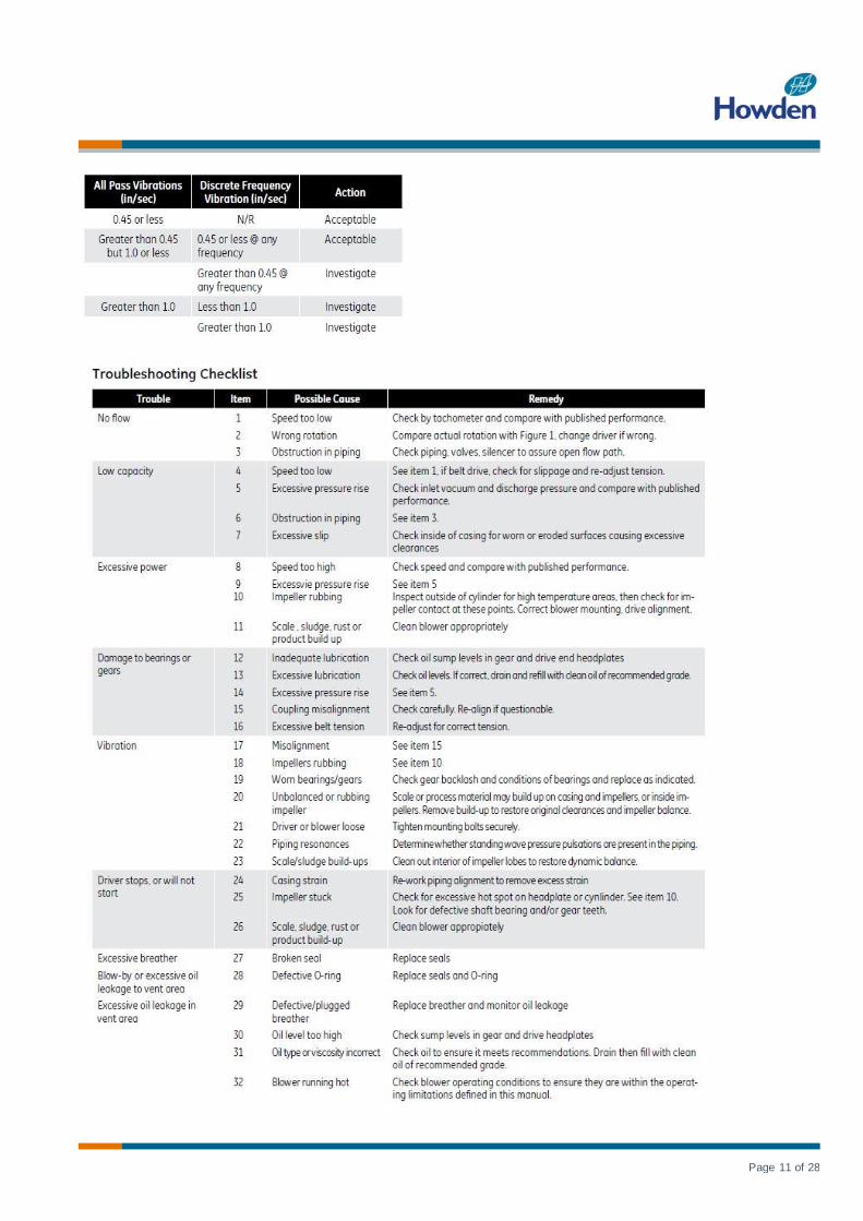
Refer to the TROUBLESHOOTING CHECKLIST for
suggestions on various problems that may appear.
The blower should now be ready for continuous duty
operation at full load. During the first few days make
periodic checks to determine whether all conditions
remain steady, or at least acceptable. This may be
particularly important if the blower is supplying air to a
process system where conditions can vary. At the first
opportunity, stop the blower and clean the temporary
inlet protective screen. If no appreciable amount of
debris has collected, the screen may be removed. See
comments under INSTALLATION. At this same time,
verify levelling, coupling alignment or belt tension, and
mounting bolt tightness.
Should operating experience prove that blower capacity
is a little too high for the actual air requirements, a small
excess may be blown off continuously through the
manual unloading or vent valve. Never rely on the
pressure relief valve as an automatic vent. Such use
may cause the discharge pressure to become
excessive, and can also result in unsafe operation of the
valve itself. If blower capacity appears to be too low,
refer to the TROUBLESHOOTING CHECKLIST.
Vibration Assessment Criteria
With measurements taken at the bearing locations on
the housings, see chart below for an appropriate
assessment guide for rotary lobe blowers rigidly
mounted on stiff foundations.
In general, blower vibration levels should be monitored
on a regular basis and the vibration trend observed for
progressive or sudden change in level. If such a change
occurs, the cause should be determined through
spectral analysis.
As shown on the chart below, the level of all pass
vibration will determine the need to measure discrete
frequency vibration levels and the action required.
Page 11 of 28

Page 12 of 28
Inspection & Maintenance: Roots
Universal RAI series blowers
A good program of consistent inspection and
maintenance is the most reliable method of minimizing
repairs to a blower. A simple record of services and
dates will help keep this work on a regular schedule.
Basic service needs are:
Lubrication
Checking for hot spots
Checking for increases or changes in vibration and
noise
Recording of operating pressures and temperatures
Above all, a blower must be operated within its specified
rating limits, to obtain satisfactory service life.
A newly installed blower should be checked often during
the first month of full-time operation. Attention thereafter
may be less frequent assuming satisfactory
performance. Lubrication is normally the most important
consideration and weekly checks of lubricant levels in
the gearbox and bearing reservoirs should be
customary. Complete oil change schedules are
discussed under LUBRICATION.
Driver lubrication practices should be in accordance with
the manufacturer’s instructions. If direct connected to
the blower through a lubricated type coupling, the
coupling should be checked and greased each time
blower oil is changed. This will help reduce wear and
prevent unnecessary vibration. In a belted drive system,
check belt tension periodically and inspect for frayed or
cracked belts.
In a new, and properly installed, unit there is no contact
between the two impellers, or between the impellers and
cylinder or headplates. Wear is confined to the bearings
(which support and locate the shafts) the oil seals, and
the timing gears. All are lubricated and wear should be
minimal if clean oil of the correct grade is always used.
Seals are subject to deterioration as well as wear, and
may require replacement at varying periods.
Shaft bearings are designed for optimum life under
average conditions with proper lubrication and are
critical to the service life of the blower. Gradual bearing
wear may allow a shaft position to change slightly, until
rubbing develops between impeller and casing. This will
cause spot heating, which can be detected by observing
these surfaces. Sudden bearing failure is usually more
serious. Since the shaft and impeller are no longer
supported and properly located, extensive general
damage to the blower casing and gears is likely to
occur.
Oil seals should be considered expendable items, to be
replaced whenever drainage from the headplate vent
cavity becomes excessive or when the blower is
disassembled for any reason. Some oil seal leakage
may occur since an oil film under the lip is required for
proper operation. Periodically leaked oil should be wiped
off from surfaces. Minor seal leakage should not be
considered as indicating seal replacement.
Timing gear wear, when correct lubrication is
maintained, should be negligible. Gear teeth are cut to
provide the correct amount of backlash, and gears
correctly mounted on the shafts will accommodate a
normal amount of tooth wear without permitting contact
between lobes of the two impellers. However, too high
an oil level will cause churning and excessive heating.
This is indicated by unusually high temperature at the
bottom of the gear housing. Consequent heating of the
gears will result in loss of tooth-clearance, backlash and
rapid wear of the gear teeth usually will develop.
Continuation of this tooth wear will eventually produce
impeller contacts (knocking), and from this point serious
damage will be unavoidable if blower operation is
continued. A similar situation can be produced suddenly
by gear tooth fracture, which is usually brought on by
sustained overloading or momentary shock loads.
Problems may also develop from causes other than
internal parts failure. Operating clearances within a
blower are only a few thousandths of an inch. This
makes it possible for impeller interference or casing rubs
to result from shifts in the blower mounting or from
changes in piping support. If this type of trouble is
experienced, and the blower is found to be clean, try
removing mounting strains. Loosen blower mounting
bolts and reset the levelling and drive alignment. Then
tighten mounting again, and make sure that all piping
meets blower connections accurately and squarely
Foreign materials in the blower will also cause trouble,
which can only be cured by disconnecting the piping and
thoroughly cleaning the blower interior.
A wide range of causes and solutions for operating
troubles are covered in the TROUBLE SHOOTING
CHECKLIST. The remedies suggested should be
performed by qualified mechanics with a good
background. Major repairs generally are to be
considered beyond the scope of maintenance, and
should be referred to an authorized Howden Roots
distributor.
Warranty failures should not be repaired at all, unless
specific approval has been obtained through Howden
Roots before starting work. Unauthorized disassembly
within the warranty period may void the warranty.
Page 13 of 28

Page 14 of 28

Page 15 of 28

Page 16 of 28

Page 17 of 28

Page 18 of 28

Page 19 of 28

Page 20 of 28

Page 21 of 28

Page 22 of 28

Page 23 of 28

Page 24 of 28
Page 25 of 28

Page 26 of 28

Page 27 of 28

Page 28 of 28