Embed Size (px)
Citation preview
CM1N9203en_01 09 Mar 2012 Building Technologies
s 9203
920
3mm
P0
1
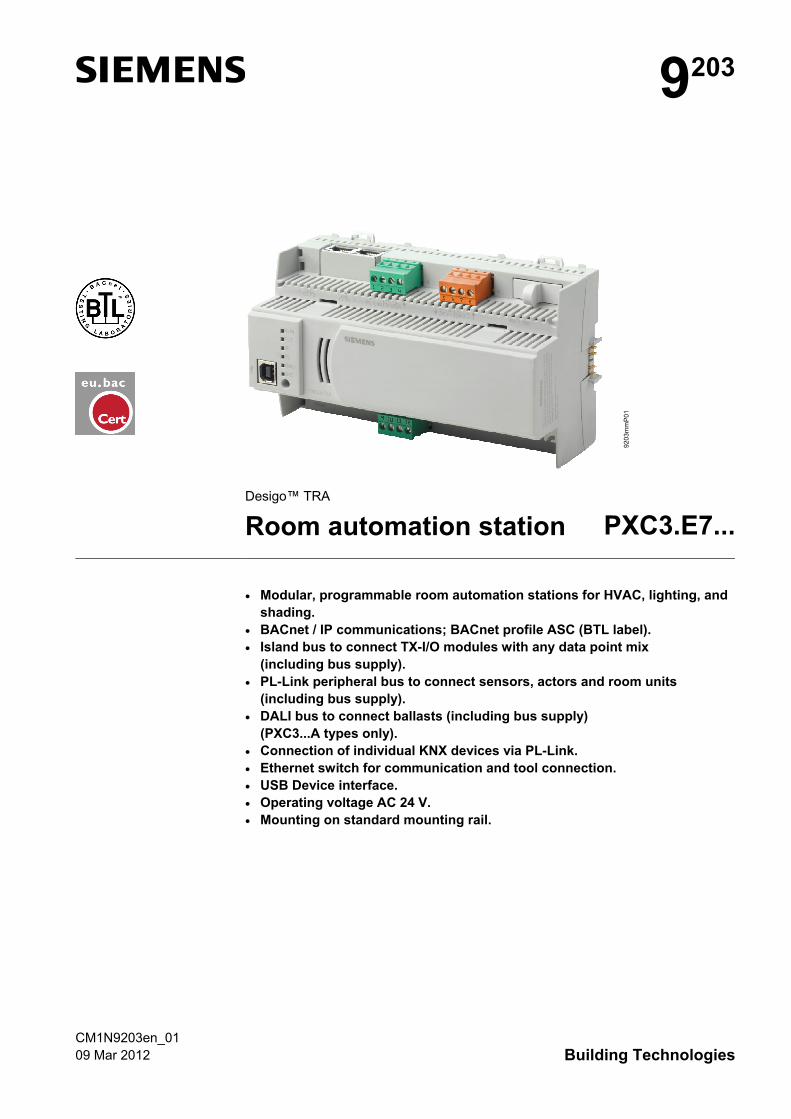
Desigo™ TRA
Room automation station PXC3.E7...
• Modular, programmable room automation stations for HVAC, lighting, and
shading. • BACnet / IP communications; BACnet profile ASC (BTL label). • Island bus to connect TX-I/O modules with any data point mix
(including bus supply). • PL-Link peripheral bus to connect sensors, actors and room units
(including bus supply). • DALI bus to connect ballasts (including bus supply)
(PXC3...A types only). • Connection of individual KNX devices via PL-Link. • Ethernet switch for communication and tool connection. • USB Device interface. • Operating voltage AC 24 V. • Mounting on standard mounting rail.
2 / 10
Siemens PXC3.E7... Room automation station CM1N9203en_01 Building Technologies 09 Mar 2012
Use
Starting with Desigo V5, PXC3 series room automation stations with Total Room Automation applications (TRA) can be used for buildings with more sophisticated requirements on functionality and flexibility. TRA is used when several disciplines (HVAC, lighting, shading) are combined to form one total solution and when total flexibility is required. TRA is perfect for solutions optimizing energy (class A) without loss of comfort.
Functions
A PXC3 series room automation station can assume control for multiple rooms.
These freely programmable room automation stations provide the infrastructure to provide and process system- and application-specific functions. • The room automation stations have a 2-port Ethernet switch to support for low-
cost cabling via line topology. • A USB Device port is available for service and commissioning. • TX-I/O modules connected directly to the PXC3 allow for direct connection of
field devices. This offers maximum flexibility. • The PL-Link peripheral bus supports room units, sensors, and actuating devices.
Plug & play allows for connecting selected Siemens field devices to the PL-Link bus (devices with the PL-Link logo). The PL-Link bus supports integration of commercially available KNX devices (S-Mode, requires ETS engineering).
• The DALI bus (with PXC3...A types) supports lighting control. Commercially available DALI EBGs (electronic ballasts) can be connected.
Type summary: Room automation stations
Product No. Stock No.
Function BACnet/IP PL-Link bus
TX-I/O modules DALI bus
PXC3.E72 S55376-C100
typically 4 rooms typically 8 room segments *)
2 interfacesmax. 64 devices
max. 72 physical I/O points
- -
PXC3.E72A S55376-C101
typically 4 rooms typically 8 room segments *)
2 interfacesmax. 64 devices
max. 72 physical I/O points
max. 64 ballasts **)
PXC3.E75 S55376-C102
typically 8 rooms typically 16 room segments *)
2 interfacesmax. 64 devices
max. 200 physical I/O points
- -
PXC3.E75A S55376-C103
typically 8 rooms typically 16 room segments *)
2 interfacesmax. 64 devices
max. 200 physical I/O points
max. 64 ballasts **)
*) Architectural building grid (also called room axis) **) Commercially available DALI -ballasts with a DALI address
Control of several rooms
Communication
3 / 10
Siemens PXC3.E7... Room automation station CM1N9203en_01 Building Technologies 09 Mar 2012
Equipment combinations
PXC3 series room automation stations can be operated with TX-I/O and PL-Link devices.
DALI support: see table below.
Peripheral devices DALI (PXC3...A types only) DALI Device Type Supported Fluorescent Lamps 0 Yes Switching Function 7 Yes Self-contained Emergency Lighting 1 No Low Voltage Halogen Lamps 3 Partly *) Conversion digital into D.C. Voltage 5 Partly *) Incandescent Lamps 4 No HID Discharge Lamps 2 No LED Modules 6 Partly *) Colour Control 8 No Sequencer 9 No Optical Control 10 No
*) Partly supported means that basic functions are supported like with type 0, but no further type specific functions.
Mechanical design
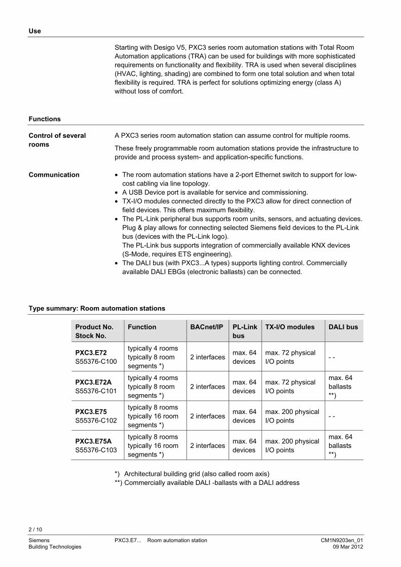
The compact build allows for mounting the devices on a standard mounting rail.
1 Plastic housing 2 Island bus plug connection 3 T 10 A fuse for AC 24 V peripheral supply via island bus 4 Plug-in terminal block (operating voltage) 5 Plug-in terminal block PL-Link 6 2-port Ethernet switch (with 2 LEDs per port for display purposes) 7 DALI bus (only active in PXC3....A types) 8 LED display for device and system status 9 USB Device interface 10 Interface for extension modules 11 Service pin 12 Service pin DALI (only in PXC3...A types) 13 Slider for mounting on DIN rail
4 / 10
Siemens PXC3.E7... Room automation station CM1N9203en_01 Building Technologies 09 Mar 2012
The bus supplies for island bus, PL-Link and DALI are integrated in the room automation station. They are switched off automatically as long as no device is connected to the respective bus in ABT.
For better reliability of the room automation station, the bus supplies and the AC 24 V outlets are independent from the room automations station's own supply.
PL-Link supply: The internal PL-Link supply must not be operated in parallel with an external supply. It must be switched off manually in the ABT (Pl-Link rail properties) when using an external supply. This is typically the case if the devices connected to the PL-Link consume more than the 160 mA available from the internal supply. See TRA installation guide CM111043 for details.
Island bus supply: The internal bus supplies can be reinforced by external power supply modules. See TRA installation guide CM111043 for details. An additional TXS1.12F10 supply module must be switched on and off at the same time as the room automation station. Otherwise, DC 24 V island bus supply may sag, resulting in alarms.
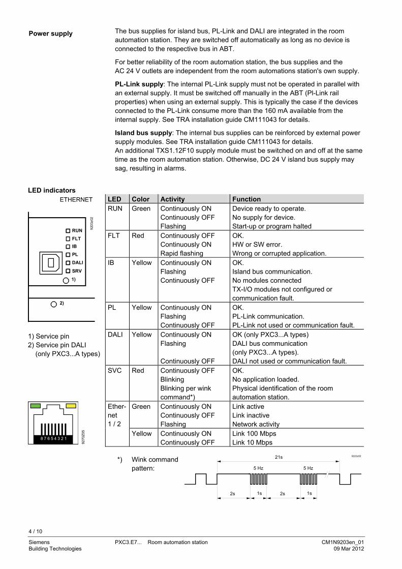
LED indicators
LED Color Activity Function RUN Green Continuously ON
Continuously OFF Flashing
Device ready to operate. No supply for device. Start-up or program halted
FLT Red Continuously OFF Continuously ON Rapid flashing
OK. HW or SW error. Wrong or corrupted application.
IB Yellow Continuously ON Flashing Continuously OFF
OK. Island bus communication. No modules connected TX-I/O modules not configured or communication fault.
PL Yellow Continuously ON Flashing Continuously OFF
OK. PL-Link communication. PL-Link not used or communication fault.
DALI Yellow Continuously ON Flashing Continuously OFF
OK (only PXC3...A types) DALI bus communication (only PXC3...A types). DALI not used or communication fault.
SVC Red Continuously OFF Blinking Blinking per wink command*)
OK. No application loaded. Physical identification of the room automation station.
Green Continuously ON Continuously OFF Flashing
Link active Link inactive Network activity
ETHERNET
920
3z02
RUN
FLT
IB
PL
DALI
SRV
1)
2)
1) Service pin 2) Service pin DALI (only PXC3...A types)
9270
Z05
8 7 6 5 4 3 2 1
Ether-net 1 / 2
Yellow Continuously ON Continuously OFF
Link 100 Mbps Link 10 Mbps
*) Wink command
pattern:
2s 1s
21s
5 Hz 5 Hz
9222z02
2s 1s
Power supply
5 / 10
Siemens PXC3.E7... Room automation station CM1N9203en_01 Building Technologies 09 Mar 2012
Service pins Pin Action Description 1) Short press Physical identification of the room automation station in the
network (Ethernet). 2) Short press DALI test: All ballasts On or Off. Long press DALI test: Start / stop the following function:
"All ballasts blink (2 s On, 2 s Off)".
Product documentation
• Engineering and commissioning: See ABT online help. • Installation: See installation manual Desigo TRA, CM111043.
Engineering
• Cable length, topology, etc.: See installation manual Desigo TRA, CM111043. • Each device has a unique identification number for commissioning support.
It is also located on the removable barcode label: See the ABT online help for the associated workflow.
• Each device has a unique serial number.
Mounting
The room automation stations can be snapped onto a standard mounting rail.
The automation station has pluggable screw terminal blocks to connect the AC 24 V supply, the AC 24 V outlets, the PL-Link, and the DALI bus.
The TX-I/O modules are snapped onto the mounting rail on the right side of the room automation station. The island bus is created automatically in this process.
Recommended With restrictions *) • Wall, horizontal from left to right
or from right to left • Wall, vertical from bottom to top.
• Over head. • On a horizontal surface. • Wall, vertical from top to bottom.
Ambient temperature -5...50 °C Ambient temperature -5...45 °C *) *) 50°C is admissible if the bus supplies use max. 2/3 of the specified load: PL-
Link 105mA, DALI 85mA and island bus 400mA. You must ensure, however, that sufficient ventilation is available to maintain the permissible ambient temperature for the devices (inside the cabinet / installation box). Outside, the temperature should be 10 K lower.
Installation
See installation manual Desigo TRA, CM111043.
Island bus Polarity: If a TXS1.12F10 supply module is connected to output
24 V, do not exchange ~ and ⊥.
The devices are not damaged but island bus communication will not work.
Mounting position
Note
STOP . Note!
6 / 10
Siemens PXC3.E7... Room automation station CM1N9203en_01 Building Technologies 09 Mar 2012
Commissioning
In order to prevent equipment damage and/or personal injuries always follow local safety regulations and the required safety standards. See the help file of the Setup and service assistant (SSA) for commissioning details. Access for the tools to the room automation station is provided by the following interfaces on the room automation station
− Ethernet switch (BACnet/IP). − USB Device interface (serves for FW download and generally for access to the entire
LAN. For details see SSA (Setup & Service Assistant) Commissioning, CA111050). The ABT supports stop / pause / resume of the application: • HALT / RUN, e.g. to debug the code. • STOP / RUN for a restart of the application.
Disposal
The devices are considered electronics devices for disposal in terms of European Directive 2002/96/EC (WEEE) and may not be disposed of as domestic waste. Dispose of the devices via the proper channels. Follow all local and currently applicable laws and regulations.
Technical data
Operating voltage (24V~, ⊥ )
Safety extra-low voltage SELV or protection by extra-low voltage PELV Half-wave load
AC 24 V -15 % / +20% 48...63 Hz Symmetric
Power consumption Max. permissible input current AC 24 V (through terminals 5 and 6)
Total max. 10 A (Ext. fusing compulsory)
Base load (without loading by modules and field devices)
8 VA / 0.33 A
Island bus supply DC 24 V / max. 600 mA
30 VA / 1.25 A
PL-Link supply DC 29 V / max. 160 mA *)
12 VA / 0.50 A
*) The bus supply can be switched off manually via ABT if not used. Factory setting: "Auto detection"
DALI supply DC 16 V / max. 128 mA
9 VA / 0.37 A
Transit power AC 24 V TX-IO: AC 24V / 6 A (island bus)
PL-Link: AC 24V / 2 A(terminals 3 and 4) AC 24 V / 6 A
(terminals 7 and 8, for additional AV 24 V consumers)
144 VA / 6 A 48 VA / 2 A 144 VA / 6 A (only if the sum of 10 A at ter-minals 5 and 6 is not exceeded)
Response to power / communication failure
• Energy reserve (supercap) to support real-time clock (3 days). • Start-up time after power failure: approx. 90 s
Interfaces for tool access
Pause / restart of the application
7 / 10
Siemens PXC3.E7... Room automation station CM1N9203en_01 Building Technologies 09 Mar 2012
Fuse AC 24 V /2 A (PL-Link, terminals 3 and 4)
PTC resistor, short-circuit proof
AC 24 V (terminals 7 and 8) No internal fusing Island bus conductor V~ T 10A fuse (slow, exchangeable) Ethernet interface Plug 2 x RJ45, screened Interface type 100BaseTX, IEEE 802.3 compatible Bit rate 10 / 100 Mbps, autosensing Protocol BACnet over UDP/IP USB interface Plug Type B (USB device) Data rate (USB 1.1) 12MBit/s Galvanic isolation of ⊥ No Protective circuit against surges and
over current Yes (balancing currents are limited, also in the GND conductor)
Island bus interface DC output Nominal voltage DC 24V Max. supply 600 mA
(sufficient for typically 8 TX-I/O modules) Parallel switchable with 3 supply
modules TXS1.12F10 For details, see: TX-I/O planning and installation manual, CM110562)
Short-circuit proof, overload-proof Self-resetting Communications Interface type Siemens specific protocol Protection Short-circuit proof
Island bus connector on side
Protection against faulty wiring with AC 24 V
No electric protection. Use the terminal cover.
PL-Link interface Interface type KNX, galvanically separated Transceiver TP-UART Baud rate 9.6 kbps Bus power supply
Note: for devices with higher power requirement, use the output AC 24 V 2 A, see above.
160 mA for max 32 PL-Link devices Default: Auto detection; must be turned off via ABT if external bus supply is used. Up to 64 PL-Link devices can be opera-ted using one or two external bus supplies.
Protection Short-circuit proof Protection against miswiring up to AC 24 V
DALI interface Interface type DALI, galvanically separated (only PXC3....A types) Baud rate 1.2 kBit/s Insulation strength Reinforced insulation for 230 V (1.5 kV)
Suitable for installations in overvoltage category III (4 kV).
Bus power supply 128 mA for max 64 DALI devices Protection Short-circuit proof
Upon power-on, AC 230 V bus voltage is recognized on terminals DA+ and DA–.
NO protection against miswiring with AC 24 V or AC 230 V: Voltage between DA+ / DA+ or between DA– / DA– will destroy the DALI PCB!
Wiring, topology, cable length
See installation manual TRA, CM111043.

8 / 10
Siemens PXC3.E7... Room automation station CM1N9203en_01 Building Technologies 09 Mar 2012
Connection terminals, plug-in
Construction type Cu-wire or Cu-strand with wire end sleeve Cu-strand without wire end sleeve
Pluggable screw terminals 1 x 0.6 mm dia. to 2.5 mm2 or 2 x 0.6 mm dia. to 1,0 mm2 1 x 0.6 mm dia. to 2.5 mm2 or 2 x 0.6 mm∅ to 1.5 mm2
Screwdriver Slot screws Screwdriver, size 1
Max. tightening torque 0.6 Nm Cable lengths and wire cross sections
See Desigo TRA installation guide, CM111043
Assignment as per EN 60730
Operation of automatic controller Degree of pollution Construction type
Type 1 2 Protection class III
Housing protection standard
Protection type as per EN 60529 Front parts in the DIN section Terminal part
IP30 IP20
Ambient conditions Operation Climatic conditions Temperature Humidity
Mechanical conditions
As per IEC 60721-3-3 Class 3K5 –5 ... 50 / 45 °C (see page 5) 5…95% r.h. Class 3M2
Transport Climatic conditions Temperature Humidity
Mechanical conditions
As per IEC 60721-3-2 Class 2K3 -25...70 °C 5…95% r.h. Class 2M2
Standards, directives and approvals
Product safety Automatic electrical controls devices for household and similar use
EN 60730-1
General requirements for Home and Building Electronic Systems (HBES) and Building Automation and Control Systems (BACS) - Part 3: Electrical safety requirements
EN 50491-3
Electromagnetic compatibility Immunity (industry & residential) EN 60730-1 Emissions (residential) EN 60730-1 General requirements for Home and
Building Electronic Systems (HBES) and Building Automation and Control Systems (BACS) - Part 3: Electrical safety requirements
EN 50491-5-3
CE conformity Electromagnetic compatibility
2004/108/EU
C-tick conformity (EMC) AS/NZS 61000-6-3. UL approbation UL 916 eu.bac: Satisfies the requirements for eu.bac certification. License numbers as per product list on:
http://www.eubaccert.org/licences-by-criteria.asp Environmental compatibility
The product environmental declaration CM1E9203 contains data on environmentally compatible product design and assessments (RoHS compliance, materials composition, packaging, environmental benefit, disposal)
ISO 14001 (Environment) ISO 9001 (Quality) SN 36350 (Environmentally compatible products) 2002/95/EG (RoHS)
9 / 10
Siemens PXC3.E7... Room automation station CM1N9203en_01 Building Technologies 09 Mar 2012
Color Housing RAL 7035 (light-gray) Dimensions Housing as per DIN 43 880, see dimensions Weight With / without packaging 373g / 349g
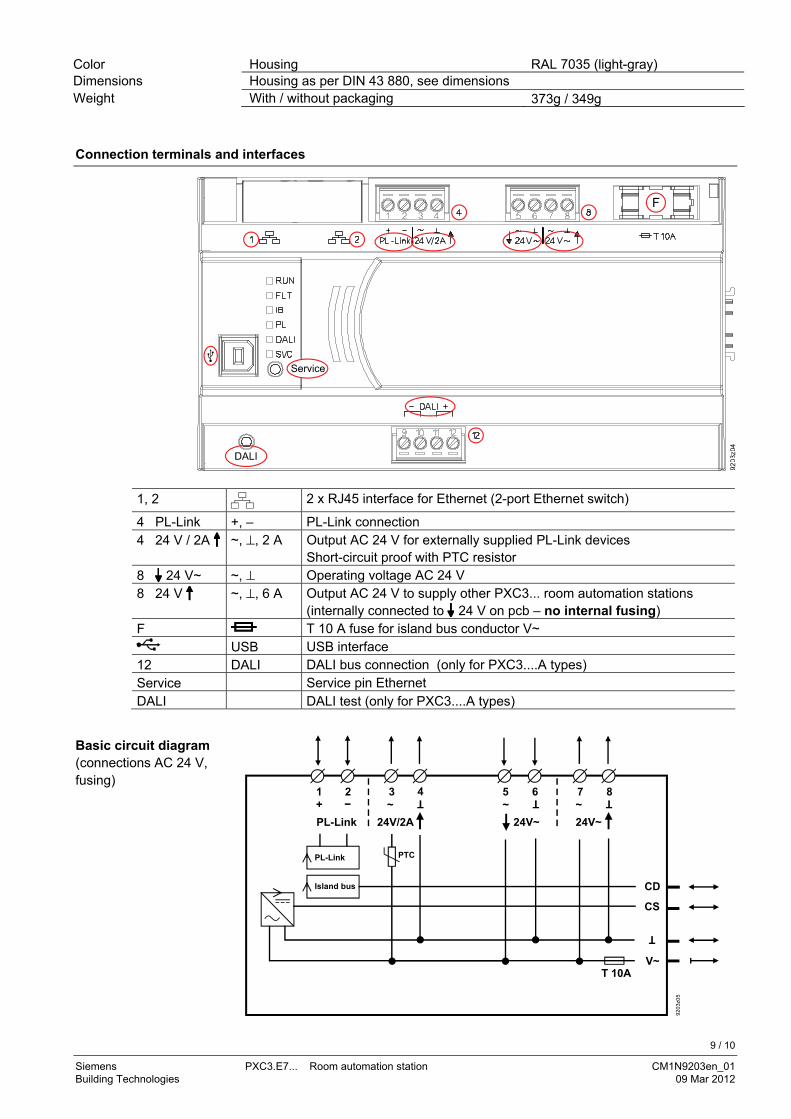
Connection terminals and interfaces
1, 2 2 x RJ45 interface for Ethernet (2-port Ethernet switch)
4 PL-Link +, – PL-Link connection 4 24 V / 2A ~, ⊥, 2 A Output AC 24 V for externally supplied PL-Link devices
Short-circuit proof with PTC resistor 8 24 V~ ~, ⊥ Operating voltage AC 24 V 8 24 V ~, ⊥, 6 A Output AC 24 V to supply other PXC3... room automation stations
(internally connected to 24 V on pcb – no internal fusing) F T 10 A fuse for island bus conductor V~
USB USB interface 12 DALI DALI bus connection (only for PXC3....A types) Service Service pin Ethernet DALI DALI test (only for PXC3....A types)
24V~
CS
5 6 7 8
V~
920
3z0
5
T 10A
1 2 3 4~
24V~24V/2APL-Link
+ ~ ~
PTCPL-Link
Island bus
Basic circuit diagram (connections AC 24 V, fusing)
10 / 10
Siemens PXC3.E7... Room automation station CM1N9203en_01 Building Technologies 09 Mar 2012
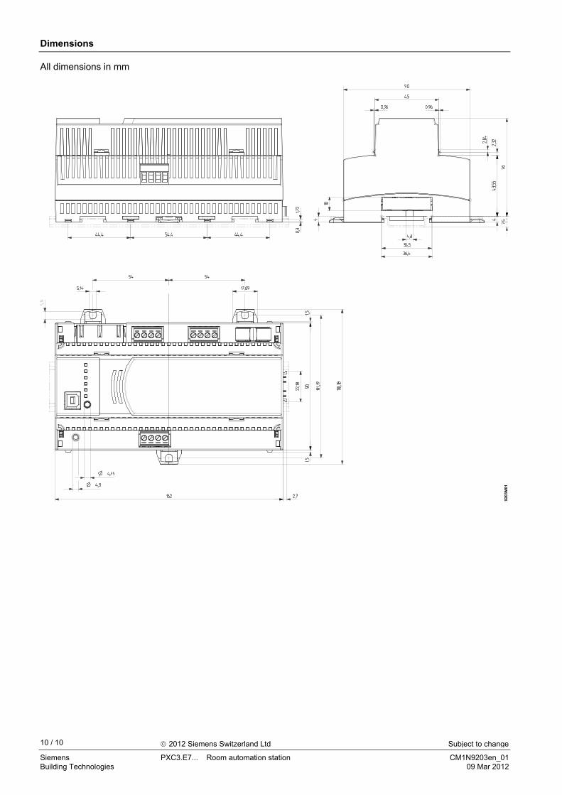
Dimensions
9203
M01
All dimensions in mm
2012 Siemens Switzerland Ltd Subject to change


![W5 abdomen[1]](https://img.pdfslide.us/doc/110x75/577d2e9e1a28ab4e1eaf8a9e/w5-abdomen1.jpg)