Embed Size (px)
Citation preview
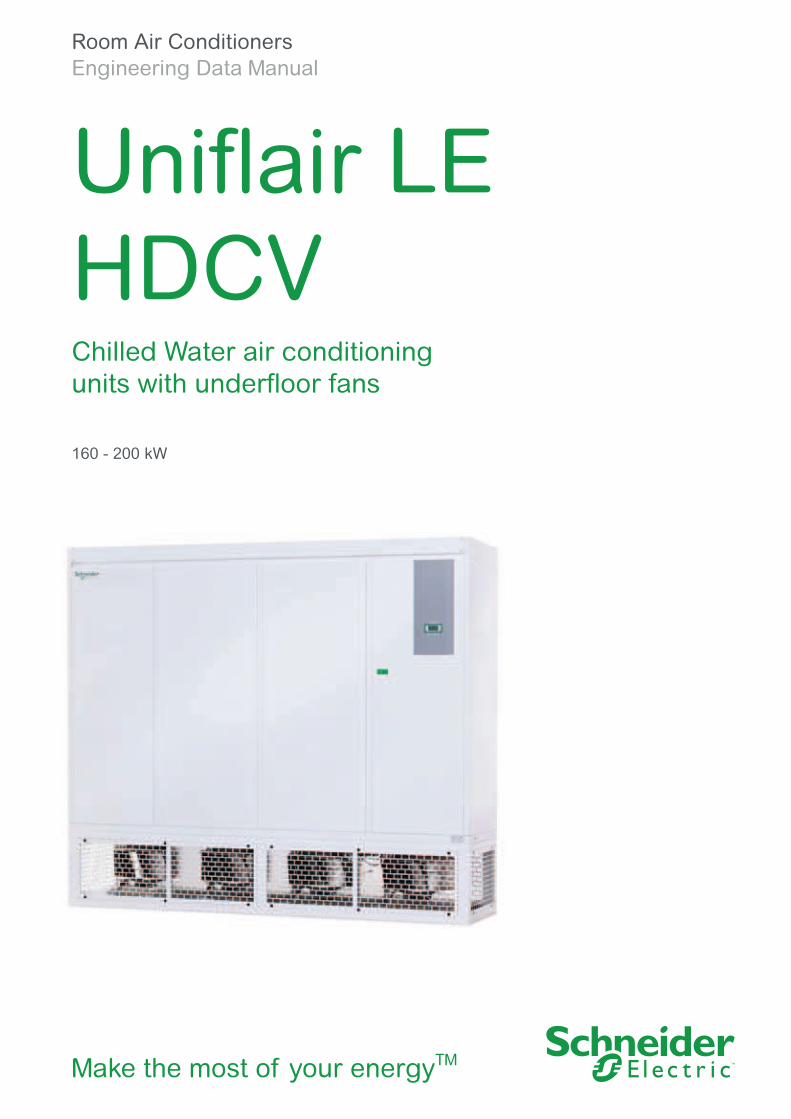
Room Air Conditioners
Engineering Data Manual
Uniflair LEHDCV Chilled Water air conditioning units with underfloor fans
160 - 200 kW
Make the most of your energyTM


Uniflair LE - HDCV Contents
General introduction 5
Main components 11
Technical Data 23
Technical Drawings 42
3

Uniflair LE - HDCV General introduction
Basic unit
HDCV - Single and Dual coil series
Introduction 6
Main functions 7
Available Options
Power Supply 8
Fan Module Configuration Options 8
Plenum and Floor Stands 8
AFPS (Automatic Floor Pressurization System) 9
Other options 9
5
General introduction Basic unit HDCV - Single and Dual coil series
Introduction The Unit is made of two sections to grant installation of fan module under or
above the raised floor and to increase the coil surface for energy efficiency
maximization.
The units designed for modern Data Centers are optimized for Underfloor
fan module installation in order to minimize power consumption.
The units can be configured for installation above the raised floor choosing
the fan module configuration.
Thanks to their optimized design and extensive laboratory testing, these
units provide reduced electrical absorption, a greater ability to maintain
elevated efficiency levels even at partial loads, rationalized regulation and
the possibility to communicate with a wide range of supervision protocols.
The units have been designed and optimized according the latest ASHRAE
trends. Airflow requires a room layout which features hot and cold aisles.
In the suction section of the rack (cold aisle) the air temperature must be
maintained at a constant level for the whole height of the rack; a temperature
between 18°C and 27°C depending on the manufacturer, while the hot
aisles located at the discharge section of the rack have a temperature
between 30 and 38°C depending on the active thermal load.
Humidity has to be maintained inside an envelope identified by a max rH of
60%, and dew point temperature between 5,5°C and 15°C.
Particular attention has been paid to reducing fans energy consumption
by optimizing the aeraulic circuit and by using fans with electronically
commutated motors. These solutions are integrated with a sophisticated
air flow management system and underfloor pressure control.
6

Main functions Unit made of two sections in order to guarantee installation of fan module
under or above the raised floor and to increase the coil surface for energy
efficiency maximization.
■ Electronically Commutated EC Fans for efficiency maximization, statically
and dynamically balanced;
■ Large Surface Copper and aluminum cooling coil for pressure drop
minimization;
■ EC Fan Module equipped with circular plug in connectors for quick and
failure free installation; the module is supplied with safety protection
grilles on the sides in case of underfloor installation;
■ Adjustable fan speed regulation according to Energy saving and Load
Sharing logics;
■ Electric panel complying with EC standards (2006 /95 /EC and EMC
2004/108/EC directives), auxiliary transformer;
■ High efficiency pleated air filter housed in a metal frame and filter
differential pressure switch;
■ Low airflow differential pressure alarm switch;
■ Full frontal accessibility for maintenance;
■ Chilled Water Inlet Temperature measurement integrated in the
microprocessor;
■ Integrated Discharge Temperature Control and Room Moisture Control;
■ Immersed electrode Humidifier;
■ Electrical Heaters with aluminum finned heating elements;
■ Phase sequence control;
■ Line reactance for each compressor to stabilize the power supply;
■ Phase sequence control and minimum / maximum power supply and
voltage;
■ Single Coil: One chilled water circuit equipped with 2 or 3 Way valve
equipercentual integrated with the microprocessor with PID logic.
Regulation logic can be chosen according to different strategies for
energy efficiency maximization;
■ Dual Coil: Unit equipped with two separate chilled water circuits equipped
with 2 or 3 Way valve equipercentual integrated with the microprocessor
with PID logic. Regulation logic can be chosen according to different
strategies for energy efficiency maximization and for circuit operation;
■ Fan module 550mm high grilles on the frontal, back and sides, fully open
on the bottom;
■ Evoluted Microprocessor control system UG50 including:
□ local user terminal with external display
□ inlet chilled water temperature monitoring
□ integrated LAN card for connecting more than one unit to
the local area network
□ clock card integrated
□ integrated RS485 serial card for direct connection to external
BMS (Modbus)
□ Second slot for additional serial card for BMS connection (optional);
■ Microprocessor control system in addition allows:
□ management of double set-point from remote control
□ free-contact for general alarm and 2 for addressable alarms
□ remote ON-OFF switch
□ Possibility to Integrate with Uniflair Chillers through
Optimized Management Logic
□ ability to interface with main BMS protocols
7
General introduction Available options
Power supply ■ Single power supply
Standard arrangement
■ Single power supply with Ultra capacitor
Thanks to the presence of Ultacapacitor and an optimized logic, in case
of power loss the microprocessor is maintained active for a time duration
related to the charging time of the device, ensuring in this way a quick
start once power is restored.
■ Double power supply with automatic changeover
and Ultracapacitor
Thanks to this option the unit is suitable for installations on TIER III and
IV installations. The unit is fitted with an integrated electromechanical
automatic changeover with manual pre selection of the preferred line. The
unit automatically commutates to the active line. During the commutation
the control board works thanks to the presence of the Ultracapacitor and
a dedicated software logic of management.
Thanks to the presence of Ultacapacitor and an optimized logic, in case
of power loss the microprocessor is maintained active for a time duration
related to the charging time of the device, ensuring in this way a quick
start once power is restored.
■ User Terminal, RS485 serial card
The standard arrangement permits a direct connection to a BMSs based
on serial lines.
Fan Module Configuration Options ■ Fan Module Open on all sides suggested for installation Under the
Raised Floor
■ Fan Module Closed on all sides and open on the bottom suggested
for installation above the Raised Floor
■ Fan Module Open on the front suggested for installation with front
discharge required
■ Fan Module Open on the back suggested for installation with back
discharge required
Plenum and Floor Stands ■ High Efficiency Plenum including Bag Filters
The unit can be equipped with a 500mm plenum that includes high
efficiency bag filters minimizing the pressure drops and the fan power
consumption.
■ Filter grades
According to the filtration grade different codes are available, from EU4
to EU7
■ Air intake plenum (height 500 mm) installed between the top of the
unit and a false ceiling or to the air delivery channel.
■ Air intake plenum with high-efficiency air filters ranging from class
EU6 to class EU8.
■ Air intake plenum with motorized damper
■ Base frame for assembly on a raised floor. The main frame is adjustable
in height up to 600 mm
8

AFPS (Automatic Floor Pressurization System) ■ Automatic Floor Pressurization System can be configured as an
option mounted in the unit granting that the unit automatically adapts
to the variation of the room configuration granting the pressure required
under the raised floor;
Other options ■ Chilled Water Outlet Temperature measurement integrated in the
microprocessor can be chosen as an option
■ Filter option
■ Condensate drain pump
■ Energy meter
■ Packing suitable for container transportation
The unit is equipped with the device can be transported inside a standard
container.
9

Uniflair LE - HDCV Main Components
Coil Module Frame 12
Fan Module Frame 12
Fans 13
Cooling Coil 14
Box Type air filters 14
Plenum with Bag type Air filters 14
Low airflow and clogged filter alarm sensors 14
Hydraulic circuit 14
Humidifier 15
Electrical panel 16
Ultracapacitor 16
Electrical panel: double electrical supply (optional) 16
Microprocessor control - UG50 17
Energy Meter 18
Discharge Temperature Control and Moisture Control 18
Dehumidification with limitation of the cooling capacity 19
Fan speed Management 19
Dual Coil Regulation Logic 19
Optimized Management 19
AFPS 20
Optional accessories 21
Certification standards 21
11
Main components Main components
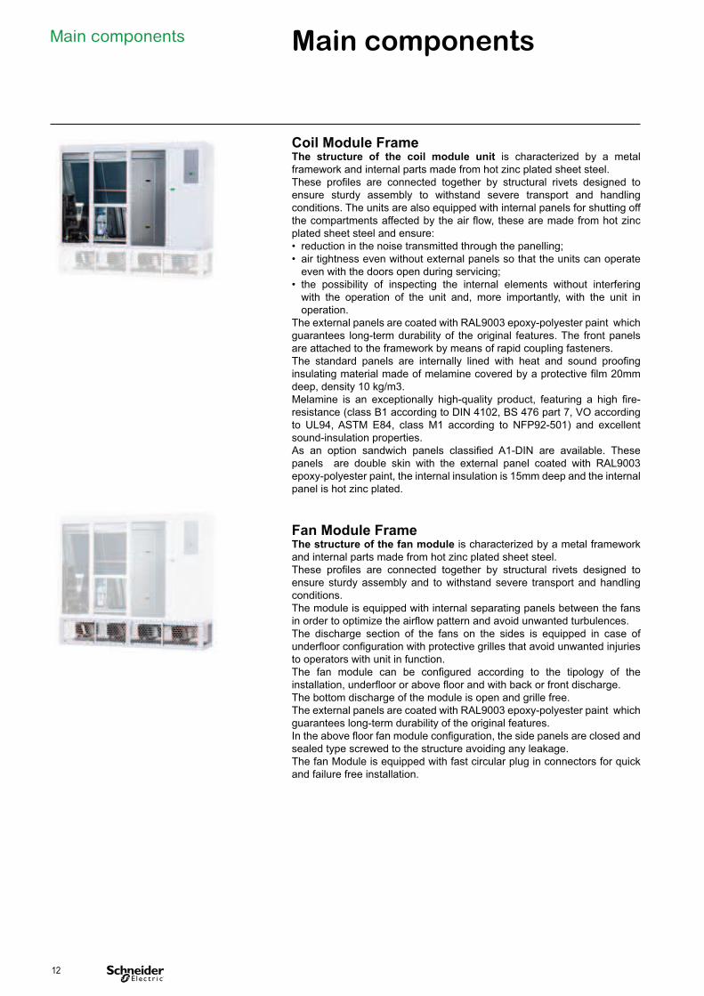
Coil Module Frame The structure of the coil module unit is characterized by a metal
framework and internal parts made from hot zinc plated sheet steel.
These profiles are connected together by structural rivets designed to
ensure sturdy assembly to withstand severe transport and handling
conditions. The units are also equipped with internal panels for shutting off
the compartments affected by the air flow, these are made from hot zinc
plated sheet steel and ensure:
• reduction in the noise transmitted through the panelling;
• air tightness even without external panels so that the units can operate
even with the doors open during servicing;
• the possibility of inspecting the internal elements without interfering
with the operation of the unit and, more importantly, with the unit in
operation.
The external panels are coated with RAL9003 epoxy-polyester paint which
guarantees long-term durability of the original features. The front panels
are attached to the framework by means of rapid coupling fasteners.
The standard panels are internally lined with heat and sound proofing
insulating material made of melamine covered by a protective film 20mm
deep, density 10 kg/m3.
Melamine is an exceptionally high-quality product, featuring a high fire-
resistance (class B1 according to DIN 4102, BS 476 part 7, VO according
to UL94, ASTM E84, class M1 according to NFP92-501) and excellent
sound-insulation properties.
As an option sandwich panels classified A1-DIN are available. These
panels are double skin with the external panel coated with RAL9003
epoxy-polyester paint, the internal insulation is 15mm deep and the internal
panel is hot zinc plated.
Fan Module Frame The structure of the fan module is characterized by a metal framework
and internal parts made from hot zinc plated sheet steel.
These profiles are connected together by structural rivets designed to
ensure sturdy assembly and to withstand severe transport and handling
conditions.
The module is equipped with internal separating panels between the fans
in order to optimize the airflow pattern and avoid unwanted turbulences.
The discharge section of the fans on the sides is equipped in case of
underfloor configuration with protective grilles that avoid unwanted injuries
to operators with unit in function.
The fan module can be configured according to the tipology of the
installation, underfloor or above floor and with back or front discharge.
The bottom discharge of the module is open and grille free.
The external panels are coated with RAL9003 epoxy-polyester paint which
guarantees long-term durability of the original features.
In the above floor fan module configuration, the side panels are closed and
sealed type screwed to the structure avoiding any leakage.
The fan Module is equipped with fast circular plug in connectors for quick
and failure free installation.
12
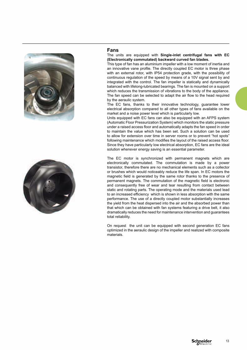
Fans The units are equipped with Single-inlet centrifugal fans with EC
(Electronically commutated) backward curved fan blades.
This type of fan has an aluminium impeller with a low moment of inertia and
an innovative vane profile. The directly coupled EC motor is three phase
with an external rotor, with IP54 protection grade, with the possibility of
continuous regulation of the speed by means of a 10V signal sent by and
integrated with the control. The fan impeller is statically and dynamically
balanced with lifelong-lubricated bearings. The fan is mounted on a support
which reduces the transmission of vibrations to the body of the appliance.
The fan speed can be selected to adapt the air flow to the head required
by the aeraulic system.
The EC fans, thanks to their innovative technology, guarantee lower
electrical absorption compared to all other types of fans available on the
market and a noise power level which is particularly low.
Units equipped with EC fans can also be equipped with an AFPS system
(Automatic Floor Pressurization System) which monitors the static pressure
under a raised access floor and automatically adapts the fan speed in order
to maintain the value which has been set. Such a solution can be used
to allow for extension over time in server rooms or to prevent “hot spots”
following maintenance which modifies the layout of the raised access floor.
Since they have particularly low electrical absorption, EC fans are the ideal
solution whenever energy saving is an essential parameter.
The EC motor is synchronized with permanent magnets which are
electronically commutated. The commutation is made by a power
transistor, therefore there are no mechanical elements such as a collector
or brushes which would noticeably reduce the life span. In EC motors the
magnetic field is generated by the same rotor thanks to the presence of
permanent magnets. The commutation of the magnetic field is electronic
and consequently free of wear and tear resulting from contact between
static and rotating parts. The operating mode and the materials used lead
to an increased efficiency which is shown in less absorption with the same
performance. The use of a directly coupled motor substantially increases
the yield from the heat dispersed into the air and the absorbed power than
that which can be obtained with fan systems featuring a drive belt, it also
dramatically reduces the need for maintenance intervention and guarantees
total reliability.
On request the unit can be equipped with second generation EC fans
optimized in the aeraulic design of the impeller and realized with composite
materials.
13
Main components
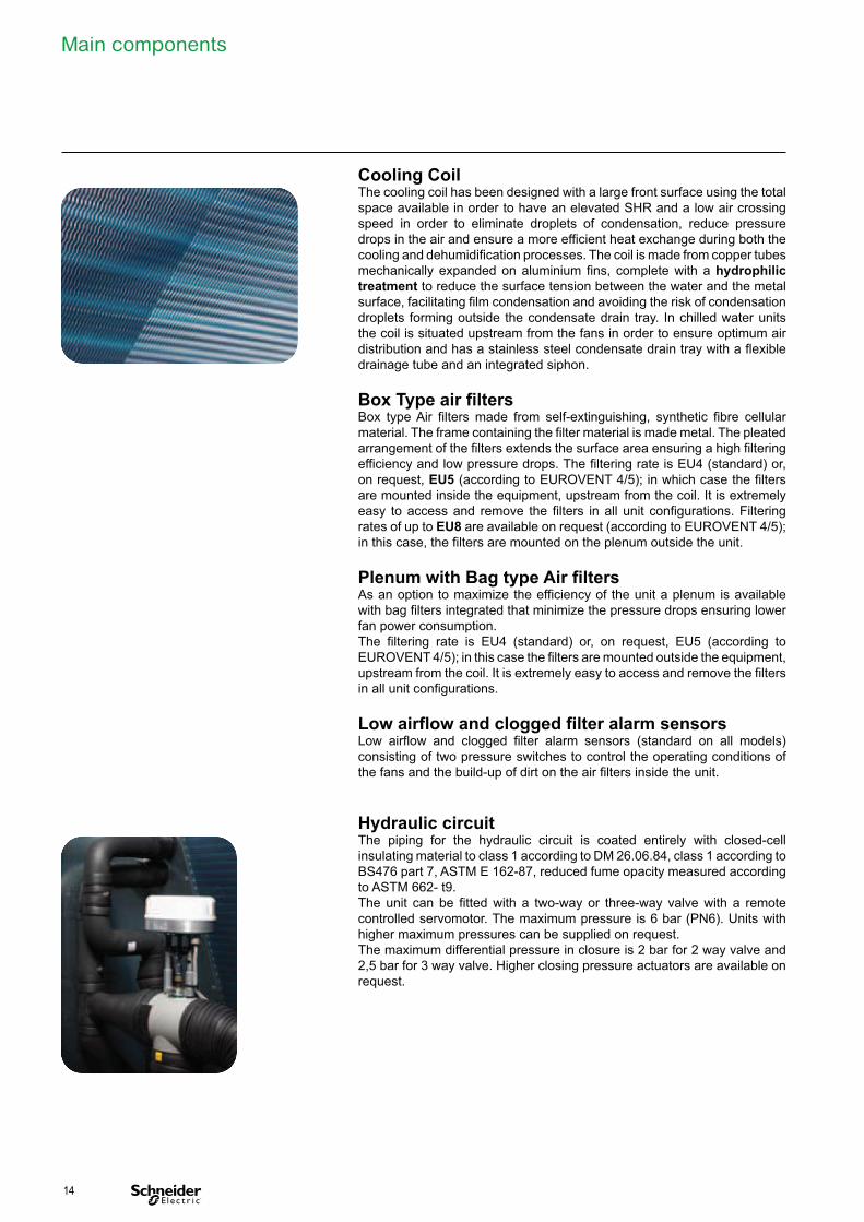
Cooling Coil The cooling coil has been designed with a large front surface using the total
space available in order to have an elevated SHR and a low air crossing
speed in order to eliminate droplets of condensation, reduce pressure
drops in the air and ensure a more efficient heat exchange during both the
cooling and dehumidification processes. The coil is made from copper tubes
mechanically expanded on aluminium fins, complete with a hydrophilic
treatment to reduce the surface tension between the water and the metal
surface, facilitating film condensation and avoiding the risk of condensation
droplets forming outside the condensate drain tray. In chilled water units
the coil is situated upstream from the fans in order to ensure optimum air
distribution and has a stainless steel condensate drain tray with a flexible
drainage tube and an integrated siphon.
Box Type air filters Box type Air filters made from self-extinguishing, synthetic fibre cellular
material. The frame containing the filter material is made metal. The pleated
arrangement of the filters extends the surface area ensuring a high filtering
efficiency and low pressure drops. The filtering rate is EU4 (standard) or,
on request, EU5 (according to EUROVENT 4/5); in which case the filters
are mounted inside the equipment, upstream from the coil. It is extremely
easy to access and remove the filters in all unit configurations. Filtering
rates of up to EU8 are available on request (according to EUROVENT 4/5);
in this case, the filters are mounted on the plenum outside the unit.
Plenum with Bag type Air filters As an option to maximize the efficiency of the unit a plenum is available
with bag filters integrated that minimize the pressure drops ensuring lower
fan power consumption.
The filtering rate is EU4 (standard) or, on request, EU5 (according to
EUROVENT 4/5); in this case the filters are mounted outside the equipment,
upstream from the coil. It is extremely easy to access and remove the filters
in all unit configurations.
Low airflow and clogged filter alarm sensors Low airflow and clogged filter alarm sensors (standard on all models)
consisting of two pressure switches to control the operating conditions of
the fans and the build-up of dirt on the air filters inside the unit.
Hydraulic circuit The piping for the hydraulic circuit is coated entirely with closed-cell
insulating material to class 1 according to DM 26.06.84, class 1 according to
BS476 part 7, ASTM E 162-87, reduced fume opacity measured according
to ASTM 662- t9.
The unit can be fitted with a two-way or three-way valve with a remote
controlled servomotor. The maximum pressure is 6 bar (PN6). Units with
higher maximum pressures can be supplied on request.
The maximum differential pressure in closure is 2 bar for 2 way valve and
2,5 bar for 3 way valve. Higher closing pressure actuators are available on
request.
14
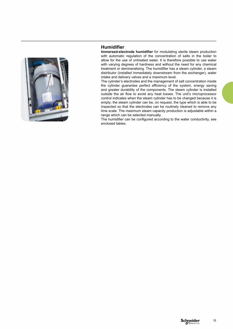
Humidifier Immersed-electrode humidifier for modulating sterile steam production
with automatic regulation of the concentration of salts in the boiler to
allow for the use of untreated water. It is therefore possible to use water
with varying degrees of hardness and without the need for any chemical
treatment or demineralising. The humidifier has a steam cylinder, a steam
distributor (installed immediately downstream from the exchanger), water
intake and delivery valves and a maximum level.
The cylinder’s electrodes and the management of salt concentration inside
the cylinder guarantee perfect efficiency of the system, energy saving
and greater durability of the components. The steam cylinder is installed
outside the air flow to avoid any heat losses. The unit’s microprocessor
control indicates when the steam cylinder has to be changed because it is
empty; the steam cylinder can be, on request, the type which is able to be
inspected so that the electrodes can be routinely cleaned to remove any
lime scale. The maximum steam capacity production is adjustable within a
range which can be selected manually.
The humidifier can be configured according to the water conductivity, see
enclosed tables.
15

Main components
Electrical panel Electrical panel is located in a compartment separated from the air
flow and made in compliance with the 2006/95/EC directive and related
standards. The main features are as follows:
• a three-phase power supply 400V / 3ph + N / 50Hz for all of the units
except single coil units where the neutral is only present when there is an
optional condensate drain pump;
• low voltage secondary circuit 24Vac with isolation transformer;
• plastic isolating screen for protection from live components;
• general isolator with mechanical interlock;
• thermomagnetic circuit-breakers for protection;
• terminal board for no-voltage signal and control contacts.
All of the units undergo a safety test cycle to check the continuity of the
protection circuit and the insulation resistance and a voltage test (dielectric
strength).
Ultracapacitor Ultracapacitor module is an optional electronic device integrated in the
units that guarantees temporarily supply to the control in case of lack of
power supply.
This function permits to minimize the restart time of the Uniflair Close
Control and Chiller units avoiding the re boot time of the microprocessor.
The module avoids microprocessor switch off in case of Voltage dips,
short interruption and voltage variations according to test performed in
compliance with CEI EN 61000-4-11:2006-02, EN 61000-4-11:2004-08,
IEC 61000- 4-11:2004-03 part 4-11.
The module, integrated in the units by means of dedicated management
software, is implemented by buffer Ultracap capacitors, whose recharge is
autonomously managed by the module.
The device does not require special safety and pollution provisions, as lead
acid batteries are not used.
In case of power failure, capacitors release the stored energy until it is
not exhausted, the minimum time guaranteed with the Ultacapacitor fully
charged is 2 minutes. When power is reset, the capacitors start re-charging.
4 minutes of continuous charge is required, to have enough energy to
guarantee the active control until the subsequent lack of power.
Uniflair microprocessor displays the module charge status and the operating
mode ( Normal or Emergency).
Electrical panel: double electrical supply (optional) With the aim of guaranteeing a redundancy even in terms of electrical
supply the HDCV units can be provided with the option of double power
supply with automatic commutation.
The unit, thanks to an electro-mechanical changeover can be connected to
two separate electric lines, generally with one connected to a principal line
and the other to a generator or emergency line.
In case the principal line is not defined, the unit autonomously switches
over to the other, at the same time verifying an eventual return of supply.
When the principal line becomes available again the supply is restored to
this line.
The principal line can be chosen through a manual preselector.
As this solution allows both definition of the priority line and the frequency of
checking, the units equipped with double power supply guarantee absolute
continuity of service.
The double power supply is equipped with Ultra Capacitor device in order
to minimize the restart time during the changeover between line A and B.
16
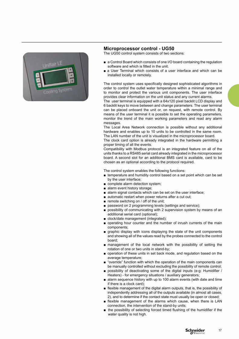
Microprocessor control - UG50 The UG50 control system consists of two sections:
■ a Control Board which consists of one I/O board containing the regulation
software and which is fitted in the unit.
■ a User Terminal which consists of a user interface and which can be
installed locally or remotely.
The control system uses specifically designed sophisticated algorithms in
order to control the outlet water temperature within a minimal range and
to monitor and protect the various unit components. The user interface
provides clear information on the unit status and any current alarms.
The user terminal is equipped with a 64x120 pixel backlit LCD display and
6 backlit keys to move between and change parameters. The user terminal
can be placed onboard the unit or, on request, with remote control. By
means of the user terminal it is possible to set the operating parameters,
monitor the trend of the main working parameters and read any alarm
messages.
The Local Area Network connection is possible without any additional
hardware and enables up to 10 units to be controlled in the same room.
The LAN number of the unit is visualized in the microprocessor board.
The clock card option is already integrated in the hardware permitting a
proper timing of all the events.
Compatibility with Modbus protocol is an integrated feature on all of the
units thanks to a RS485 serial card already integrated in the microprocessor
board. A second slot for an additional BMS card is available, card to be
chosen as an optional according to the protocol required.
The control system enables the following functions:
■ temperature and humidity control based on a set point which can be set
by the user interface;
■ complete alarm detection system;
■ alarm event history storage;
■ alarm signal contacts which can be set on the user interface;
■ automatic restart when power returns after a cut out;
■ remote switching on / off of the unit;
■ password on 2 programming levels (settings and service);
■ possibility of communicating with 2 supervision system by means of an
additional serial card (optional);
■ clock/date management (integrated);
■ operating hour counter and the number of inrush currents of the main
components;
■ graphic display with icons displaying the state of the unit components
and showing all of the values read by the probes connected to the control
board;
■ management of the local network with the possibility of setting the
rotation of one or two units in stand-by;
■ operation of these units in set back mode, and regulation based on the
average temperature;
■ “override” function with which the operation of the main components can
be manually controlled without excluding the possibility of remote control;
■ possibility of deactivating some of the digital inputs (e-g: Humidifier /
Heaters) - for emergency situations / auxiliary generators;
■ alarm sequence history with up to 100 alarm events (with date and time
if there is a clock card);
■ flexible management of the digital alarm outputs, that is, the possibility of
independently addressing all of the outputs available (in almost all cases,
2), and to determine if the contact state must usually be open or closed;
■ flexible management of the alarms which cause, when there is LAN
connection, the intervention of the stand-by units;
■ the possibility of selecting forced timed flushing of the humidifier if the
water quality is not high.
17
Main components
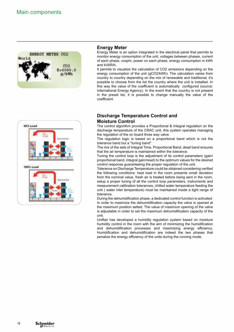
Energy Meter Energy Meter is an option integrated in the electrical panel that permits to
monitor energy consumption of the unit, voltages between phases, current
of each phase, cosphi, power on each phase, energy consumption in kWh
and kVAR/h.
It permits to visualize the calculation of CO2 emissions depending on the
energy consumption of the unit (gCO2/kWh). The calculation varies from
country to country depending on the mix of renewable and traditional, it’s
possible to choose from the list the country where the unit is installed. In
this way the value of the coefficient is automatically configured (source:
International Energy Agency). In the event that the country is not present
in the preset list, it is possible to change manually the value of the
coefficient.
Discharge Temperature Control and
Moisture Control The control algorithm provides a Proportional & Integral regulation on the
discharge temperature of the CRAC unit, this system operates managing
the regulation of the on board three way valve.
The regulation logic is based on a proportional band which is not the
tolerance band but a "tuning band".
The mix of the sets of Integral Time, Proportional Band, dead band ensures
that the air temperature is maintained within the tolerance.
Tuning the control loop is the adjustment of its control parameters (gain/
proportional band, integral gain/reset) to the optimum values for the desired
control response guaranteeing the proper regulation of the unit.
Tolerance on Discharge Temperature could be obtained considering verified
the following conditions: heat load in the room presents small deviation
from the nominal value, fresh air is treated before being sent in the room,
setup a proper tuning of all the control loop parameters, instruments and
measurement calibration tolerances, chilled water temperature feeding the
unit ( water inlet temperature) must be maintained inside a tight range of
tolerance.
During the dehumidification phase, a dedicated control function is activated.
In order to maximize the dehumidification capacity the valve is opened at
the maximum position setted. The value of maximum opening of the valve
is adjustable in order to set the maximum dehumidification capacity of the
unit.
Uniflair has developed a humidity regulation system based on moisture
humidity control in the room with the aim of minimizing the humidification
and dehumidification processes and maximizing energy efficiency.
Humidification and dehumidification are indeed the two phases that
penalize the energy efficiency of the units during the running mode.
18
Dehumidification with limitation of
the cooling capacity During the dehumidification phase, a dedicated control function is
activated.
In order to maximize the dehumidification capacity and guarantee the
discharge temperature control, the HDCV units can monitor the heat load
in the room and consequently manage the optimum valve opening in
order grant the dehumidification in the ambient maintaining the discharge
temperature inside the required tolerance. This function also integrates the
possibility of cooling coil section partialization at a constant airflow.
Fan speed Management The HDCV units can manage different logics of fan speed management in
order to minimize energy consumption.
In combination with AFPS the unit will automatically set the airflow according
the pressure set point required under the raised floor.
Alternatively the unit can adjust the airflow in combination with the heat
load present in the room with a combined regulation of the airflow from a
minimum value to a maximum value according to the valve opening.
Alternatively the unit can regulate the airflow in combination with the valve
in a serial logic i.e. the valve regulates according the room heat load and
when the unit is not able to catch the heat load the unit will increase the
airflow from a minimum value to the maximum.
Dual Coil Regulation Logic The HDCV units can manage different logics of Dual Coil, in particular
circuit one and circuit 2 can work in alternation , in sequence or in parallel
according to the plant regulation logics and TIER level request.
Optimized Management The HDCV units can be integrated with Uniflair Chillers with Optimized
Management logics.
Optimized Management allows active variation of the set point and
interactive and automatic management of the thermal load present in the
room to optimize operation in free-cooling mode in all operating conditions
without affecting reliability or temperature control precision thanks to its
sophisticated regulation logic.
Optimize Management monitors the operating parameters of all the
system elements, including the operating temperatures of the racks and
the underfl or pressure allowing complete supervision of the Data Center
cooling system.
19
Main components
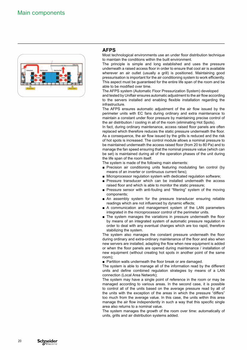
AFPS Most technological environments use an under floor distribution technique
to maintain the conditions within the built environment.
The principle is simple and long established and uses the pressure
underneath a raised access floor in order to ensure that cool air is available
wherever an air outlet (usually a grill) is positioned. Maintaining good
pressurisation is important for the air conditioning system to work efficiently.
This aspect must be guaranteed for the entire life span of the room and be
able to be modified over time.
The AFPS system (Automatic Floor Pressurization System) developed
and tested by Uniflair ensures automatic adjustment to the air flow according
to the servers installed and enabling flexible installation regarding the
infrastructure.
The AFPS ensures automatic adjustment of the air flow issued by the
perimeter units with EC fans during ordinary and extra maintenance to
maintain a constant under floor pressure by maintaining precise control of
the air distribution / cooling in all of the room (eliminating Hot Spots).
In fact, during ordinary maintenance, access raised floor panels are often
replaced which therefore reduces the static pressure underneath the floor.
As a consequence, the air flow issued by the grills is reduced and the risk
of hot spots is increased. The control module allows a nominal pressure to
be maintained underneath the access raised floor (from 20 to 80 Pa) and to
manage the fan speed ensuring that the nominal pressure value (which can
be set) is maintained during all of the operation phases of the unit during
the life span of the room itself.
The system is made of the following main elements:
■ Precision air conditioning units featuring modulating fan control (by
means of an inverter or continuous current fans);
■ Microprocessor regulation system with dedicated regulation software;
■ Pressure transducer which can be installed underneath the access
raised floor and which is able to monitor the static pressure;
■ Pressure sensor with anti-fouling and “filtering” system of the moving
components;
■ An assembly system for the pressure transducer ensuring reliable
readings which are not influenced by dynamic effects;
■ A communication and management system of the LAN parameters
integrated in the microprocessor control of the perimeter units.
■ The system manages the variations in pressure underneath the floor
by means of an integrated system of automatic pressure regulation in
order to deal with any eventual changes which are too rapid, therefore
stabilizing the system.
The system also manages the constant pressure underneath the floor
during ordinary and extra-ordinary maintenance of the floor and also when
new servers are installed, adapting the flow when new equipment is added
or when the floor panels are opened during maintenance / installation of
new equipment (without creating hot spots in another point of the same
room);
■ Partition walls underneath the floor break or are damaged.
The system is able to manage all of the information read by the different
units and define combined regulation strategies by means of a LAN
connection (Local Area Network);
The system may have a single point of reference in the room or may be
managed according to various areas. In the second case, it is possible
to control all of the units based on the average pressure read by all of
the units with the exception of the areas in which the pressure “differs”
too much from the average value. In this case, the units within this area
manage the air flow independently in such a way that this specific single
area also returns to a nominal value.
The system manages the growth of the room over time: automatically of
units, grills and air distribution systems added.
20
Optional accessories Condensate drain pump (C and electrical heaters versions).
Humidifier and condensate drain pump (D version), suitable for eliminating
the hot water produced by the humidifier.
Optional accessories supplied with the on site assembling kit
The microprocessor control system can be supplied with the following
optional cards:
• Serial adaptor RS485 card for transmitting data to a centralized supervision
system with STD or MODBUS protocol;
• TCP/ IP interface board for connecting the units to the network managed
by a BMS operating with a SMNP or TCP/IP protocol;
• LON serial card for connecting the units to a network with a BMS operating
with LON protocol;
• Fire and /or smoke detector;
• Water leak detector comprising of a control module installed inside the
electrical panel and an external sensor. Connecting numerous additional
leak detector sensors or using a sensor strip probe can be carried out in
order to check several points.
The following accessories are available:
• Air intake plenum (height 500 mm) installed between the top of the unit
and a false ceiling or to the air delivery channel. The internal panels are
lined according the two standards available for unit panel lining;
• Main frame for assembly on a raised floor. The main frame is adjustable in
height (± 25 mm) from 200 mm to 600 mm and is provided complete with
anti-vibration supports.
Certification standards Uniflair LE - HDCV are in conformity with the following directives:
■ 2006/42/EC
■ 2006/42/EC
■ 2004/108/EC
■ 2006/95/EC
21