Embed Size (px)
Citation preview
SERVICE MANUAL
ROOM AIR CONDITIONER
CONTENTS
SPECIFICATION .................................................................... 1
FUNCTIONS .......................................................................... 7
SERVICE FUNCTION EXPLANATION .................................. 9
OPERATION DETAILS ......................................................... 10
TROUBLESHOOTING GUIDE ............................................. 16
PERFORMANCE CURVE DIAGRAM .................................. 27
ELECTRIC CIRCUIT DIAGRAM .......................................... 31
EXPLODED VIEW (INDOOR UNIT) .................................... 35
EXPLODED VIEW (OUTDOOR UNIT) ................................ 37
PARTS LIST (INDOOR UNIT) .............................................. 39
PARTS LIST (OUTDOOR UNIT) .......................................... 41
TAN/TAG-A10HWI(A)TAN/TAG-A13HWI(A)TAN/TAG-A16HWI(A)
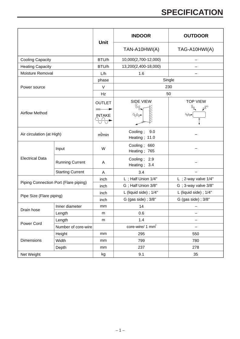
SPECIFICATION
– 1 –
Unit
BTU/hCooling Capacity
INDOOR OUTDOOR
–
BTU/hHeating Capacity –
L/h
phase
Moisture Removal –
Power source
Single
V 230
Hz 50
OUTLET
Airflow Method
SIDE VIEW TOP VIEW
INTAKE
m/minAir circulation (at High)Cooling ;
Heating ;
W
Electrical Data
Input
Running Current
Starting Current
Inner diameter
Length
Cooling ;Heating ;
–
–
ACooling ;Heating ;
–
–A
inchPiping Connection Port (Flare piping)
L L
inch G G
inchPipe Size (Flare piping)
inch
mmDrain hose
Length
Height
Width
Depth
Number of core-wirePower Cord
–
m –
m –
core-wire/ 1 mm –
mm
Dimensions mm
mm
kgNet Weight
3
2
; Half Union 1/4''
; Half Union 3/8''
L (liquid side) ; 1/4''
G (gas side) ; 3/8''
; 2-way valve 1/4''
; 3-way valve 3/8''
L (liquid side) ; 1/4''
G (gas side) ; 3/8''
TAN-A10HWI(A) TAG-A10HWI(A)
10,000(2,700-12,000)
13,200(2,400-18,000)
1.6
3.4
9.011.0
660765
2.93.4
14
0.6
1.4
295
799
237
9.1
550
780
278
35
SPECIFICATION
– 2 –
Unit
Air Circulation
INDOOR OUTDOOR
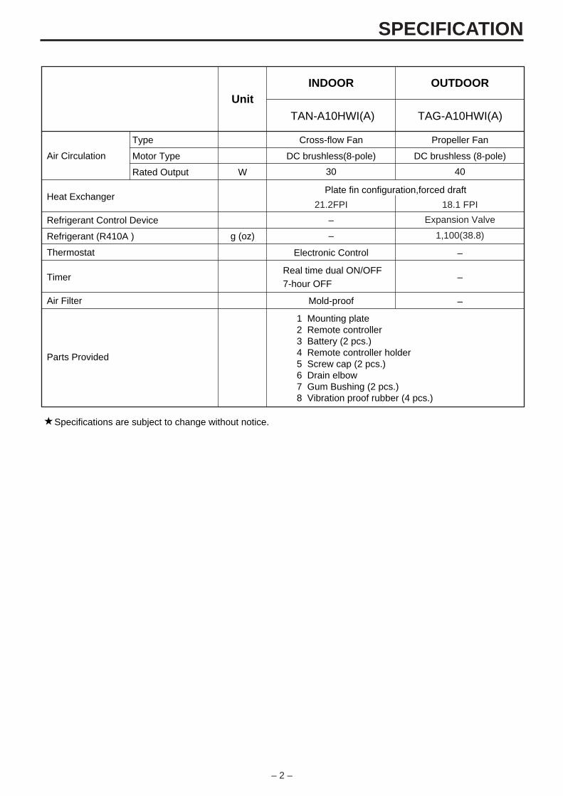
Cross-flow Fan Propeller Fan
30 40
DC brushless(8-pole) DC brushless (8-pole)
W
Heat Exchanger21.2FPI 18.1 FPI
Expansion Valve
Plate fin configuration,forced draft
Refrigerant Control Device
g (oz)Refrigerant (R410A )
–
1,100(38.8)–
Thermostat
Air Filter
Parts Provided
Electronic Control
Type
Motor Type
Rated Output
–
Mold-proof –
Specifications are subject to change without notice.
1 Mounting plate2 Remote controller3 Battery (2 pcs.)4 Remote controller holder5 Screw cap (2 pcs.)6 Drain elbow7 Gum Bushing (2 pcs.)8 Vibration proof rubber (4 pcs.)
Timer –Real time dual ON/OFF7-hour OFF
TAN-A10HWI(A) TAG-A10HWI(A)

SPECIFICATION
– 3 –
Unit
BTU/hCooling Capacity
INDOOR OUTDOOR
–
BTU/hHeating Capacity –
L/h
phase
Moisture Removal –
Power source
Single
V 230
Hz 50
OUTLET
Airflow Method
SIDE VIEW TOP VIEW
INTAKE
m/minAir circulation (at High)Cooling ;
Heating ;
W
Electrical Data
Input
Running Current
Starting Current
Inner diameter
Length
Cooling ;Heating ;
–
–
ACooling ;Heating ;
–
–A
inchPiping Connection Port (Flare piping)
L L
inch G G
inchPipe Size (Flare piping)
inch
mmDrain hose
Length
Height
Width
Depth
Number of core-wirePower Cord
–
m –
m –
core-wire/ 1 mm –
mm
Dimensions mm
mm
kgNet Weight
3
2
; Half Union 1/4''
; Half Union 3/8''
L (liquid side) ; 1/4''
G (gas side) ; 3/8''
; 2-way valve 1/4''
; 3-way valve 3/8''
L (liquid side) ; 1/4''
G (gas side) ; 3/8''
12,500(2,700-14,100)
17,100(2,400-20,700)
1.7
5.0
9.512.5
8851,130
3.95.0
14
0.6
1.4
295
799
237
9.1
550
780
278
35
TAN-A13HWI(A) TAG-A13HWI(A)

SPECIFICATION
– 4 –
Unit
Air Circulation
INDOOR OUTDOOR
Cross-flow Fan Propeller Fan
30 40
DC brushless(8-pole) DC brushless (8-pole)
W
Heat Exchanger21.2FPI 18.1 FPI
Expansion Valve
Plate fin configuration,forced draft
Refrigerant Control Device
g (oz)Refrigerant (R410A )
–
1,100(38.8)–
Thermostat
Air Filter
Electronic Control
Type
Motor Type
Rated Output
–
Mold-proof –
Specifications are subject to change without notice.
1 Mounting plate2 Remote controller3 Battery (2 pcs.)4 Remote controller holder5 Screw cap (2 pcs.)6 Drain elbow7 Gum Bushing (2 pcs.)8 Vibration proof rubber (4 pcs.)
Timer –Real time dual ON/OFF7-hour OFF
Parts Provided
TAN-A13HWI(A) TAG-A13HWI(A)

SPECIFICATION
– 5 –
Unit
BTU/hCooling Capacity
INDOOR OUTDOOR
–
BTU/hHeating Capacity –
L/h
phase
Moisture Removal –
Power source
Single
V 230
Hz 50
OUTLET
Airflow Method
SIDE VIEW TOP VIEW
INTAKE
m/minAir circulation (at High)Cooling ;
Heating ;
W
Electrical Data
Input
Running Current
Starting Current
Inner diameter
Length
Cooling ;Heating ;
–
–
ACooling ;Heating ;
–
–A
inchPiping Connection Port (Flare piping)
L L
inch G G
inchPipe Size (Flare piping)
inch
mmDrain hose
Length
Height
Width
Depth
Number of core-wirePower Cord
–
m –
m –
core-wire/ 2 mm –
mm
Dimensions mm
mm
kgNet Weight
3
2
; Half Union 1/4''
; Half Union 3/8''
L (liquid side) ; 1/4''
G (gas side) ; 3/8''
; 2-way valve 1/4''
; 3-way valve 3/8''
L (liquid side) ; 1/4''
G (gas side) ; 3/8''
16,000(1,700-18,000)
23,800(1,700-33,400)
2.8
8.1
14.015.0
1,5601,800
6.97.9
14
0.6
2.3
295
799
237
9.5
550
780
278
35
TAN-A16HWI(A) TAG-A16HWI(A)
SPECIFICATION
– 6 –
Unit
Air Circulation
INDOOR OUTDOOR
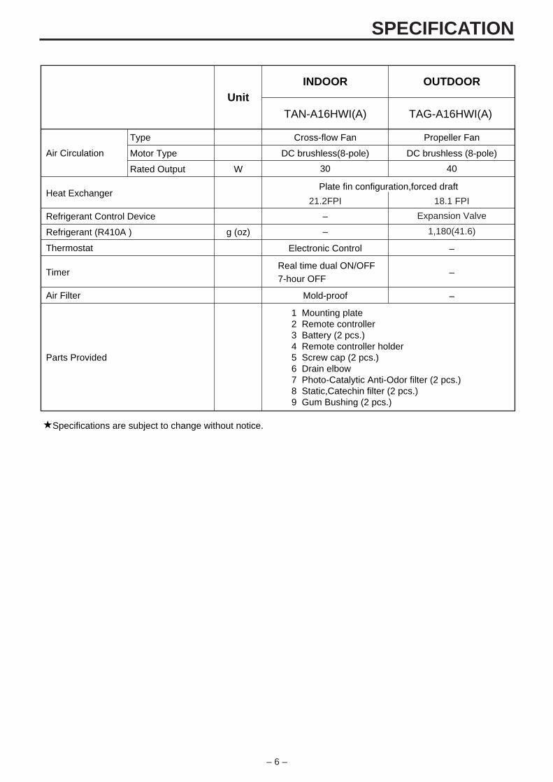
Cross-flow Fan Propeller Fan
30 40
DC brushless(8-pole) DC brushless (8-pole)
W
Heat Exchanger21.2FPI 18.1 FPI
Expansion Valve
Plate fin configuration,forced draft
Refrigerant Control Device
g (oz)Refrigerant (R410A )
–
1,180(41.6)–
Thermostat
Air Filter
Parts Provided
Electronic Control
Type
Motor Type
Rated Output
–
Mold-proof –
Specifications are subject to change without notice.
1 Mounting plate2 Remote controller3 Battery (2 pcs.)4 Remote controller holder5 Screw cap (2 pcs.)6 Drain elbow7 Photo-Catalytic Anti-Odor filter (2 pcs.)8 Static,Catechin filter (2 pcs.)9 Gum Bushing (2 pcs.)
Timer –Real time dual ON/OFF7-hour OFF
TAN-A16HWI(A) TAG-A16HWI(A)
– 7 –
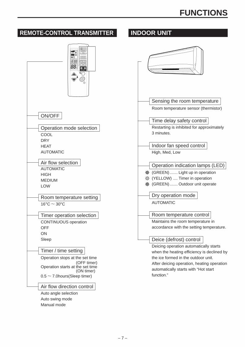
REMOTE-CONTROL TRANSMITTER
ON/OFF
Operation mode selectionCOOLDRYHEATAUTOMATIC
Air flow selectionAUTOMATICHIGHMEDIUMLOW
Room temperature setting16°C~ 30°C
Timer operation selectionCONTINUOUS operationOFFONSleep
Timer / time settingOperation stops at the set time
(OFF timer)Operation starts at the set time
(ON timer)0.5~ 7.0hours(Sleep timer)
Air flow direction controlAuto angle selectionAuto swing modeManual mode
INDOOR UNIT
Sensing the room temperatureRoom temperature sensor (thermistor)
Time delay safety controlRestarting is inhibited for approximately3 minutes.
Indoor fan speed controlHigh, Med, Low
Operation indication lamps (LED)(GREEN) ....... Light up in operation(YELLOW) .... Timer in operation(GREEN) ....... Outdoor unit operate
Dry operation modeAUTOMATIC
Room temperature controlMaintains the room temperature inaccordance with the setting temperature.
Deice (defrost) controlDeicing operation automatically startswhen the heating efficiency is declined bythe ice formed in the outdoor unit.After deicing operation, heating operationautomatically starts with “Hot startfunction.”
FUNCTIONS
– 8 –
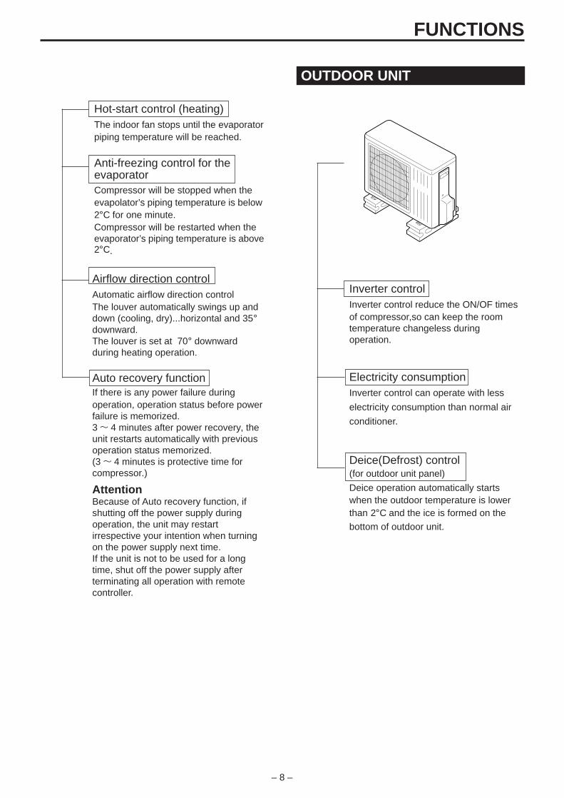
OUTDOOR UNIT
Inverter controlInverter control reduce the ON/OF timesof compressor,so can keep the roomtemperature changeless duringoperation.
Electricity consumptionInverter control can operate with less
electricity consumption than normal air
conditioner.
Deice(Defrost) control(for outdoor unit panel)
Deice operation automatically startswhen the outdoor temperature is lowerthan 2°C and the ice is formed on the
bottom of outdoor unit.
Hot-start control (heating)The indoor fan stops until the evaporatorpiping temperature will be reached.
Anti-freezing control for theevaporatorCompressor will be stopped when theevapolator’s piping temperature is below2°C for one minute.Compressor will be restarted when theevaporator’s piping temperature is above2°C.
Airflow direction controlAutomatic airflow direction controlThe louver automatically swings up anddown (cooling, dry)...horizontal and 35°downward.The louver is set at 70° downwardduring heating operation.
Auto recovery functionIf there is any power failure duringoperation, operation status before powerfailure is memorized.3~ 4 minutes after power recovery, theunit restarts automatically with previousoperation status memorized.(3~ 4 minutes is protective time forcompressor.)
AttentionBecause of Auto recovery function, ifshutting off the power supply duringoperation, the unit may restartirrespective your intention when turningon the power supply next time.If the unit is not to be used for a longtime, shut off the power supply afterterminating all operation with remotecontroller.
FUNCTIONS
– 9 –
EMERGENCY AND TEST OPERATION
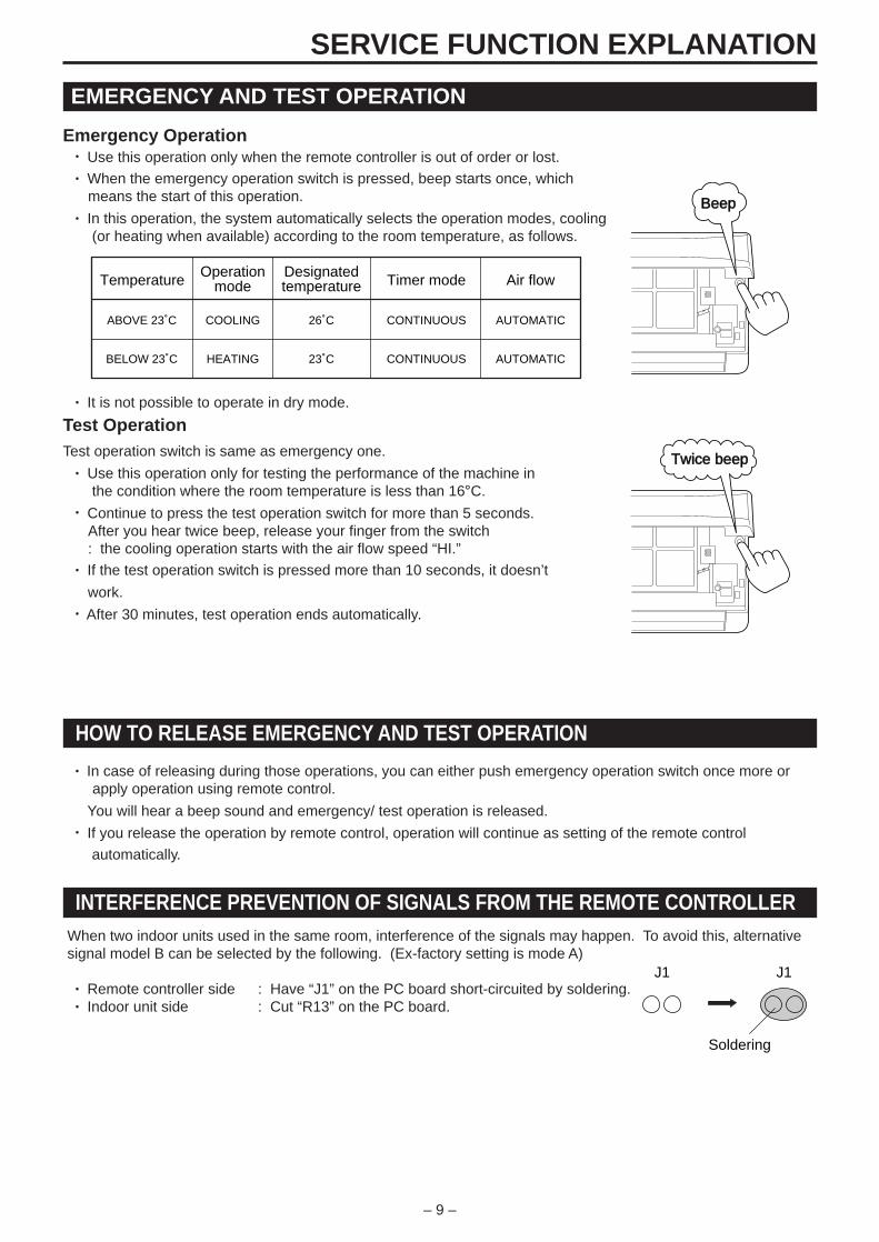
Emergency Operation• Use this operation only when the remote controller is out of order or lost.• When the emergency operation switch is pressed, beep starts once, which
means the start of this operation.• In this operation, the system automatically selects the operation modes, cooling
(or heating when available) according to the room temperature, as follows.
• It is not possible to operate in dry mode.
Test OperationTest operation switch is same as emergency one.
• Use this operation only for testing the performance of the machine in the condition where the room temperature is less than 16°C.
• Continue to press the test operation switch for more than 5 seconds.After you hear twice beep, release your finger from the switch: the cooling operation starts with the air flow speed “HI.”
• If the test operation switch is pressed more than 10 seconds, it doesn’t
work.• After 30 minutes, test operation ends automatically.
SERVICE FUNCTION EXPLANATION
J1
Soldering
J1
Temperature
ABOVE 23˚C
BELOW 23˚C
COOLING
HEATING
26˚C
23˚C
CONTINUOUS
CONTINUOUS
AUTOMATIC
AUTOMATIC
Operationmode
Designatedtemperature Timer mode Air flow
HOW TO RELEASE EMERGENCY AND TEST OPERATION
• In case of releasing during those operations, you can either push emergency operation switch once more orapply operation using remote control.
You will hear a beep sound and emergency/ test operation is released.
• If you release the operation by remote control, operation will continue as setting of the remote control
automatically.
INTERFERENCE PREVENTION OF SIGNALS FROM THE REMOTE CONTROLLERWhen two indoor units used in the same room, interference of the signals may happen. To avoid this, alternativesignal model B can be selected by the following. (Ex-factory setting is mode A)
• Remote controller side : Have “J1” on the PC board short-circuited by soldering. • Indoor unit side : Cut “R13” on the PC board.
Twice beep
Beep
– 10 –
TIMER OPERATIONON Timer operation
• Press the ON/OFF switch. Right after replacing new batteries, set the present time in advance.• Set the “ON Time” : Press the “TIME ADJ” button twice. Adjust the time with the “ , ” button. Press the “TIME ADJ” button twice.The setting of “ON Time” is completed and the present time appears on the LCD.• Set the “ON Timer” : Press the Timer fixing button “ON”.
OFF Timer operation• Press the ON/OFF switch. Right after replacing new batteries, set the present time in advance.• Set the “OFF Time” : Press the “TIME ADJ” button 3 times. Adjust the time with the “ , ” button. Press the “TIME ADJ” button once.The setting of “OFF Time” is completed and the present time appears on the LCD.• Set the “OFF Timer” : Press the Timer fixing button “OFF”.
Sleep Timer operation• Press the “SLEEP” button during the operation.• Set the operating period by pressing the “SLEEP” button until the period designated appears on the LCD.
Timer Cancellation• ON/OFF Timer : Press the Timer fixing button “ON”(On Timer) and/or “OFF”(Off Timer) once again.• Sleep Timer : Press the “SLEEP” button until the operating period on the LCD disappears.
AIRFLOW DIRECTION CONTROL
Vertical adjustment
When ON/OFF switch is pressed, the vertical louver will move to the adequate positions for each operationautomatically.
Swing of air flowIf air flow direction switch is pressed once, the vertical louver will move within the range of figures.
Fixing the flow directionIf air flow direction switch is pressed again, the vertical louver will be fixed and that position is memorized.From the next operation the louver will be set at previous position automatically.
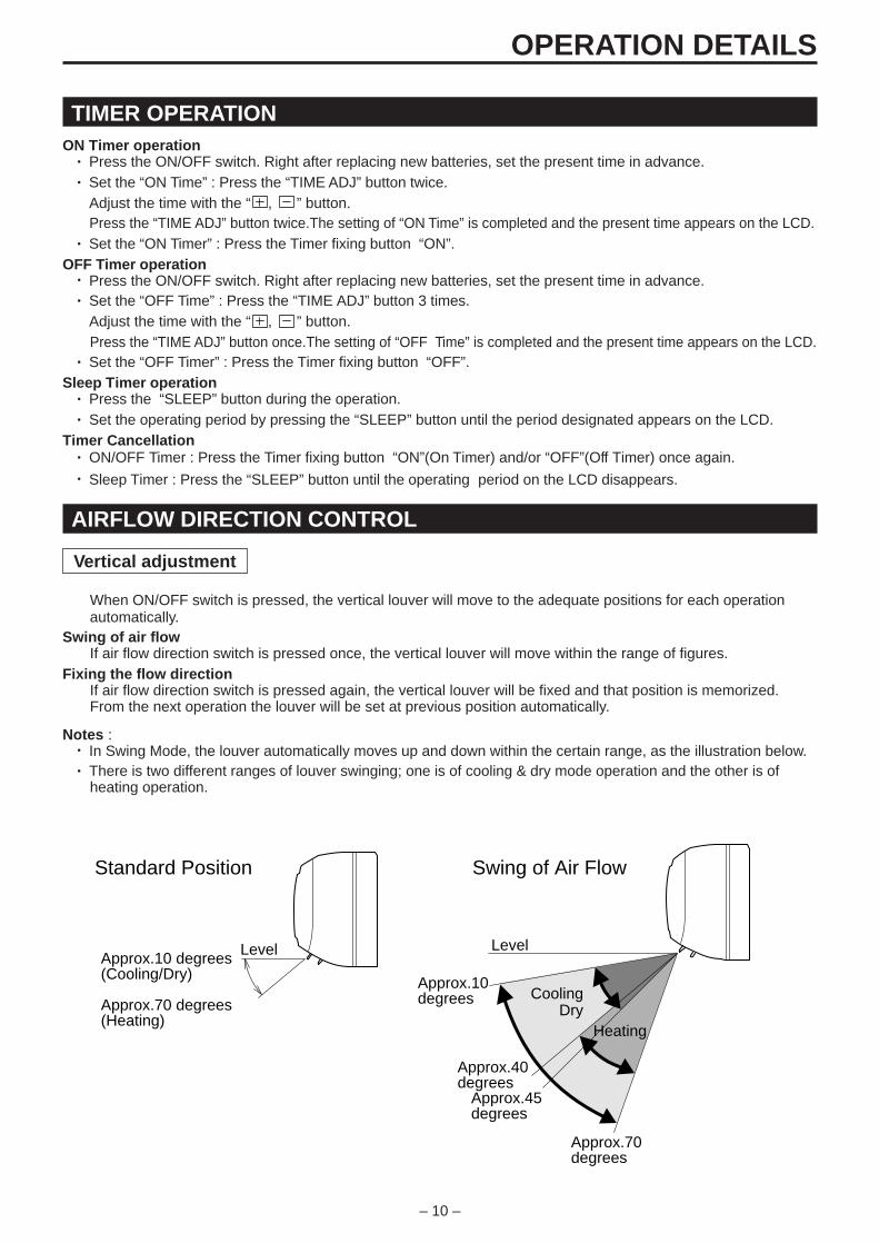
Notes :• In Swing Mode, the louver automatically moves up and down within the certain range, as the illustration below.• There is two different ranges of louver swinging; one is of cooling & dry mode operation and the other is of
heating operation.
OPERATION DETAILS
LevelApprox.10 degrees(Cooling/Dry)
Approx.70 degrees(Heating)
Standard Position
Approx.10degrees
Approx.40degrees
Approx.45degrees
Approx.70degrees
Level
Swing of Air Flow
CoolingDry
Heating
– 11 –
AIRFLOW DIRECTION CONTROL
Horizontal Adjustment
Swing of Air FlowThe horizontal louver will keep moving steadly right and left if the horizontal louver button is pressed once.
Fixing the Flow DirectionThe horizontal louver will come to a halt if the horizontal louver button is pressed once again.
NOTICE :• Dew drops may appear at the outlet under high humidity(e.g.during rainy season) if the system is operated
with the horizontal louver faced to the extreme right or left.• Use the wireless remote control unit without fail to change the angle of the horizontal louver. The horizontal
louver may move out of the normal range if forced by hands.
OPERATION DETAILS
TIME DELAY SAFETY CONTROL FUNCTION - FOR PROTECTION OF COMPRESSOR• Compressor will not restart, in any operation modes, for 3 minutes after its stop.• Compressor does not stop during the first 6 minutes of its operation even if the room temperature reaches to
the designated temperature, except changing setting temperature.
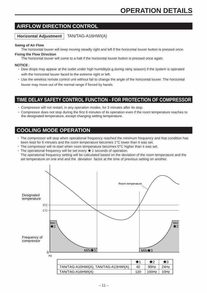
TAN/TAG-A10HWI(A), TAN/TAG-A13HWI(A)TAN/TAG-A16HWI(A)
140120
290Hz100Hz
324Hz10Hz
-1˚C
MAX2
MAX2
MIN3 MIN3
0˚C
0Hz
Frequency of compressor
Designatedtemperature
Room temperature
COOLING MODE OPERATION• The compressor will stop when operational frequency reached the minimum frequency and that condition has
been kept for 6 minutes and the room temperature becomes 1°C lower than it was set.• The compressor will re-start when room temperature becomes 0°C higher than it was set.• The operational frequency will be set every 1 seconds of operation. The operational frequency setting will be calculated based on the deviation of the room temperature and the set temperature on one end and the deviation factor at the time of previous setting on another.
TAN/TAG-A16HWI(A)
– 12 –
OPERATION DETAILS
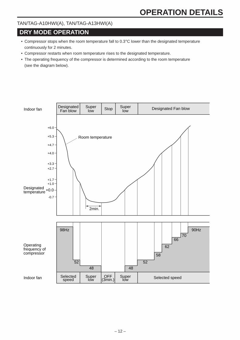
DRY MODE OPERATION• Compressor stops when the room temperature fall to 0.3°C lower than the designated temperature
continuously for 2 minutes.
• Compressor restarts when room temperature rises to the designated temperature.
• The operating frequency of the compressor is determined according to the room temperature
(see the diagram below).
98Hz 90Hz70
66
62
58
5252
4848
Operating frequency of compressor
Indoor fan
Indoor fan
Selectedspeed Selected speedSuper
lowSuper
lowOFF
(3min.)
DesignatedFan blow Designated Fan blowSuper
lowSuper
lowStop
-0.7
+1.0+1.7
+2.7
+3.3
+4.0
+4.7
+5.3
+6.0
+0.0
2min.
Designatedtemperature
Room temperature
TAN/TAG-A10HWI(A), TAN/TAG-A13HWI(A)
– 13 –
OPERATION DETAILS
Operating frequency of compressor
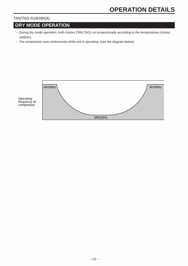
MAX30Hz MAX30Hz
MIN15Hz
DRY MODE OPERATION• During dry mode operation, both motors (TAN,TAG) run proportionally according to the temperatures (indoor,
outdoor).• The compressor runs continuously while unit is operating. (see the diagram below)
TAN/TAG-A16HWI(A)
– 14 –
OPERATION DETAILS
+3.7
30˚C
35˚C
15˚C
MAX1
MAX1
MIN2 MIN2
+4.7
0Hz
SuperLow
Frequency of compressor
Designate Fan blowLow Low or Super low Designated Fan blow
Designatedtemperature
Room temperature
Stop
Temperature, indoor heat exchanger
Indoor fan
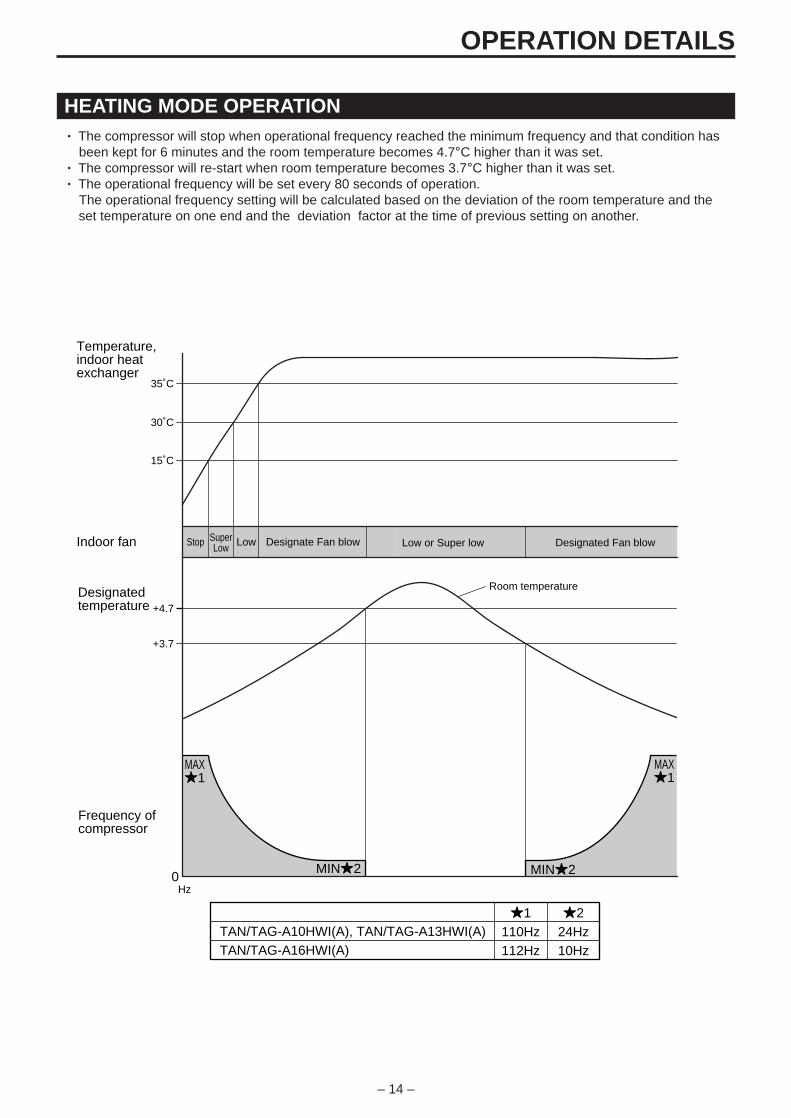
1110Hz112Hz
224Hz10Hz
TAN/TAG-A10HWI(A), TAN/TAG-A13HWI(A)TAN/TAG-A16HWI(A)
HEATING MODE OPERATION• The compressor will stop when operational frequency reached the minimum frequency and that condition has
been kept for 6 minutes and the room temperature becomes 4.7°C higher than it was set.• The compressor will re-start when room temperature becomes 3.7°C higher than it was set.• The operational frequency will be set every 80 seconds of operation. The operational frequency setting will be calculated based on the deviation of the room temperature and the set temperature on one end and the deviation factor at the time of previous setting on another.
– 15 –
Compressor
Outdoor fan
4way valve
ON OFF OFF
ON
ON
ON
ON
50Hz 67Hz MAX
2min.
3min. 2min.
50sec.
50sec.
53sec. Max 12min. 53sec.
10 sec.
2min.
-2˚C
8˚C
Defrosting starts Defrosting stop
Temperature of outdoor heat exchanger
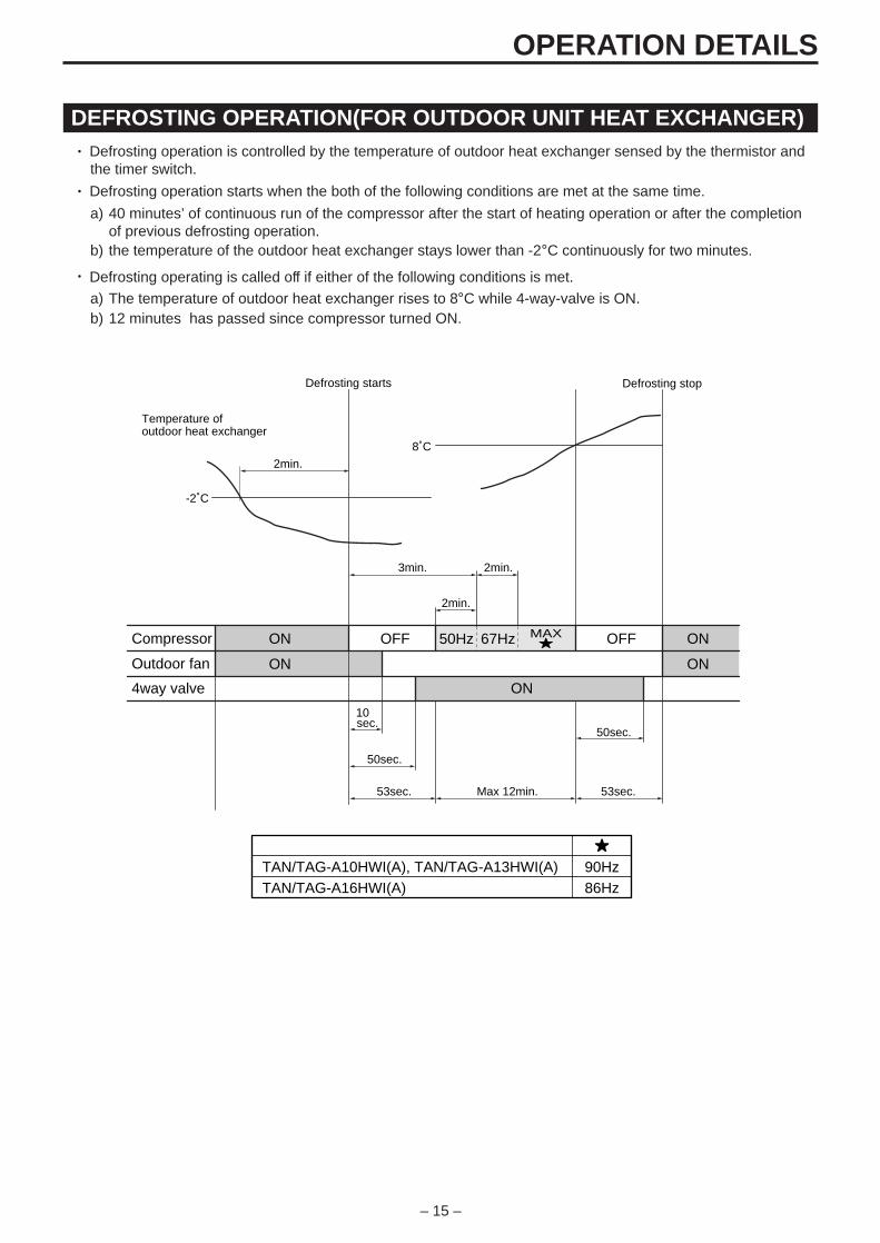
90Hz86Hz
TAN/TAG-A10HWI(A), TAN/TAG-A13HWI(A)TAN/TAG-A16HWI(A)
DEFROSTING OPERATION(FOR OUTDOOR UNIT HEAT EXCHANGER)• Defrosting operation is controlled by the temperature of outdoor heat exchanger sensed by the thermistor and
the timer switch.• Defrosting operation starts when the both of the following conditions are met at the same time.
a) 40 minutes’ of continuous run of the compressor after the start of heating operation or after the completionof previous defrosting operation.
b) the temperature of the outdoor heat exchanger stays lower than -2°C continuously for two minutes.
• Defrosting operating is called off if either of the following conditions is met.
a) The temperature of outdoor heat exchanger rises to 8°C while 4-way-valve is ON.b) 12 minutes has passed since compressor turned ON.
OPERATION DETAILS
– 16 –
TROUBLESHOOTING GUIDE
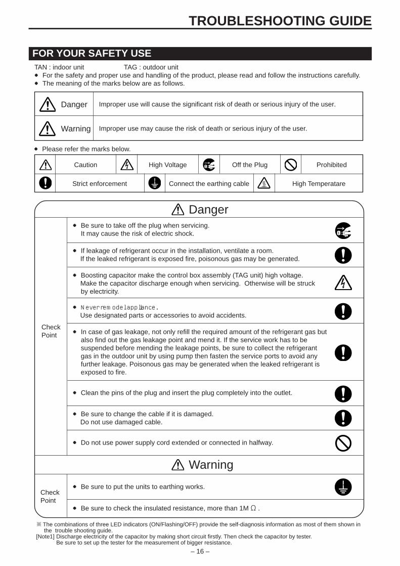
FOR YOUR SAFETY USETAN : indoor unit TAG : outdoor unit For the safety and proper use and handling of the product, please read and follow the instructions carefully. The meaning of the marks below are as follows.
Never remodel appliance. Use designated parts or accessories to avoid accidents.
In case of gas leakage, not only refill the required amount of the refrigerant gas butalso find out the gas leakage point and mend it. If the service work has to besuspended before mending the leakage points, be sure to collect the refrigerantgas in the outdoor unit by using pump then fasten the service ports to avoid anyfurther leakage. Poisonous gas may be generated when the leaked refrigerant isexposed to fire.
Clean the pins of the plug and insert the plug completely into the outlet.
Be sure to change the cable if it is damaged. Do not use damaged cable.
Do not use power supply cord extended or connected in halfway.
Be sure to put the units to earthing works.
Be sure to check the insulated resistance, more than 1MΩ .
Warning
※The combinations of three LED indicators (ON/Flashing/OFF) provide the self-diagnosis information as most of them shown in the trouble shooting guide.[Note1]
CheckPoint
CheckPoint
Be sure to take off the plug when servicing.It may cause the risk of electric shock.
If leakage of refrigerant occur in the installation, ventilate a room. If the leaked refrigerant is exposed fire, poisonous gas may be generated.
Danger
Boosting capacitor make the control box assembly (TAG unit) high voltage. Make the capacitor discharge enough when servicing. Otherwise will be struckby electricity.
Improper use will cause the significant risk of death or serious injury of the user.Danger
Warning Improper use may cause the risk of death or serious injury of the user.
Caution ProhibitedHigh Voltage
Strict enforcement Connect the earthing cable
Off the Plug
Please refer the marks below.
High Temperatare
Discharge electricity of the capacitor by making short circuit firstly. Then check the capacitor by tester.Be sure to set up the tester for the measurement of bigger resistance.
– 17 –
TROUBLESHOOTING GUIDE
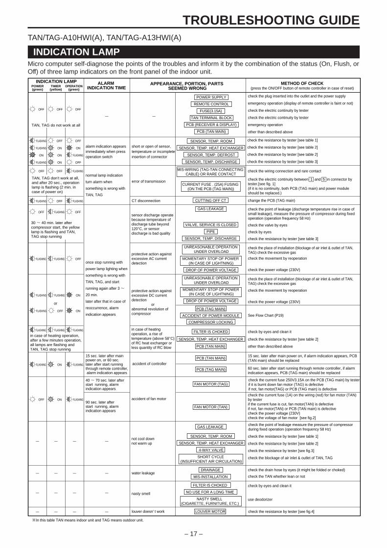
INDICATION LAMPMicro computer self-diagnose the points of the troubles and inform it by the combination of the status (On, Flush, orOff) of three lamp indicators on the front panel of the indoor unit.
ALARM INDICATION TIME
APPEARANCE, PORTION, PARTS SEEMED WRONG
MOMENTARY STOP OF POWER (IN CASE OF LIGHTNING)
DROP OF POWER VOLTAGE
check the plug inserted into the outlet and the power supply
emergency operation (display of remote controller is faint or not)
check the electric continuity by tester
check the electric continuity by tester
emergency operation
other than described above
15 sec. later after main power on, if alarm indication appears, PCB (TAN main) should be replaced
check the current fuse (1A) on the wiring (red) for fan motor (TAN) by testerif the current fuse is cut, fan motor(TAN) is defectiveif not, fan motor(TAN) or PCB (TAN main) is defectivecheck the power voltage (230V)check the voltage of fan motor [see fig.2]
METHOD OF CHECK(press the ON/OFF button of remote controller in case of reset)POWER
(green)TIMER
(yellow)OPERATION
(green)
INDICATION LAMP
OFF OFF OFF
TAN, TAG do not work at all
FLASHING OFF OFF
FLASHING ON ON
ON ON FLASHING
FLASHING ON OFF
alarm indication appears immediately when press operation switch
OFF OFF FLASHING
FLASHING OFF FLASHING
TAN, TAG don’t work at all, and after 20 sec., operation lamp is flashing (2 min. in case of power on)
normal lamp indication
turn alarm when
something is wrong with
TAN, TAG
error of transmission
CT disconnection
OFF FLASHING OFF
FLASHING FLASHING OFF
OFF
or
30 ~ 40 min. later after compressor start, the yellow lamp is flashing and TAN, TAG stop running
sensor discharge operate because temperature of discharge tube beyond 120°C, or sensor discharge is bad quality
protective action against excessive AC current detection
FLASHING FLASHING ON
FLASHING ON
FLASHING
once stop running with
power lamp lighting when
something is wrong with
TAN, TAG, and start
running again after 3 ~
20 min.
later after that in case of
reoccurrence, alarm
indication appears
protective action against excessive DC current detection orabnormal revolution of compressor
in case of heating operation, a rise of temperature (above 58°C) of RC heat exchanger or less quantity of RC blow
FLASHING FLASHING
OFF
FLASHING ON
ON
FLASHING
FLASHING
in case of heating operation, after a few minutes operation, all lamps are flashing and TAN, TAG stop running
15 sec. later after main power on, or 60 sec. later after start running through remote controller, alarm indication appears
40 ~ 70 sec. later after start running, alarm indication appears
90 sec. later after start running, alarm indication appears
accident of controller
accident of fan motor
short or open of sensor, temperature or incomplete insertion of connector
PCB (TAN MAIN)
PCB (TAG MAIN)
FAN MOTOR (TAG)
FAN MOTOR (TAN)
SENSOR, TEMP. ROOM
SENSOR, TEMP. HEAT EXCHANGER
SENSOR, TEMP. DEFROST
SENSOR, TEMP. DISCHARGE
FILTER IS CHOKED
SENSOR, TEMP. HEAT EXCHANGER
PCB (TAN MAIN)
UNREASONABLE OPERATION UNDER OVERLOAD
MOMENTARY STOP OF POWER (IN CASE OF LIGHTNING)
DROP OF POWER VOLTAGE
PCB (TAG MAIN)
ACCIDENT OF POWER MODULE
COMPRESSOR LOCKING
POWER SUPPLY
REMOTE CONTROL
FUSE(3.15A)
TAN TERMINAL BLOCK
PCB (RECEIVER & DISPLAY)
PCB (TAN MAIN)
MIS-WIRING (TAG-TAN CONNECTING CABLE) OR RARE CONTACT
CUTTING OFF CT
CURRENT FUSE . (25A) FUSING (ON THE PCB (TAG MAIN))
GAS LEAKAGE
VALVE, SERVICE IS CLOSED
PIPE
SENSOR, TEMP. DISCHARGE
check the place of installation (blockage of air inlet & outlet of TAN, TAG) check the excessive gas
check the movement by reoperation
check the power voltage (230V)
UNREASONABLE OPERATION UNDER OVERLOAD
check the place of installation (blockage of air inlet & outlet of TAN, TAG) check the excessive gas
check by eyes and clean it
check the resistance by tester [see table 2]
other than described above
check the movement by reoperation
check the power voltage (230V)
See Flow Chart (P19)
change the PCB (TAG main)
check the wiring connection and rare contact
check the resistance by tester [see table 1]
check the resistance by tester [see table 2]
check the resistance by tester [see table 2]
check the resistance by tester [see table 3]
check the point of leakage (discharge temperature rise in case of small leakage), measure the pressure of compressor during fixed operation (operation frequency 58 Hz)
check the valve by eyes
check by eyes
check the resistance by tester [see table 3]
check the electric continuity between 1 and 5 in connector by tester.[see fig. 1](if it is no continuity, both PCB (TAG main) and power module should be replaced.)
check the current fuse 250V3.15A on the PCB (TAG main) by testerif it is burnt down fan motor (TAG) is defectiveif not, fan motor(TAG) or PCB (TAG main) is defective
60 sec. later after start running through remote controller, if alarm indication appears, PCB (TAG main) should be replaced
- -
check the drain hose by eyes (it might be folded or choked)
check the TAN whether lean or not
not cool downnot warm up
water leakage
louver doesn' t work
※In this table TAN means indoor unit and TAG means outdoor unit.
check the resistance by tester [see fig.4]
check the point of leakage measure the pressure of compressor during fixed operation (operation frequency 58 Hz)
nasty smell
FILTER IS CHOKED
NO USE FOR A LONG TIME
NASTY SMELL (CIGARETTE, FURNITURE, ETC.)
DRAINAGE
MIS-INSTALLATION
LOUVER MOTOR
GAS LEAKAGE
SENSOR, TEMP. ROOM
SENSOR, TEMP. HEAT EXCHANGER
4-WAY VALVE
SHORT CYCLE (INSUFFICIENT AIR CIRCULATION)
check by eyes and clean it
use deodorizer
check the resistance by tester [see table 1]
check the resistance by tester [see table 2]
check the resistance by tester [see fig.3]
check the blockage of air inlet & outlet of TAN, TAG
- - - -
- - - -
- - - -
- - - -
TAN/TAG-A10HWI(A), TAN/TAG-A13HWI(A)
– 18 –
TROUBLESHOOTING GUIDE
CHECK A FOLLOWING STEPS
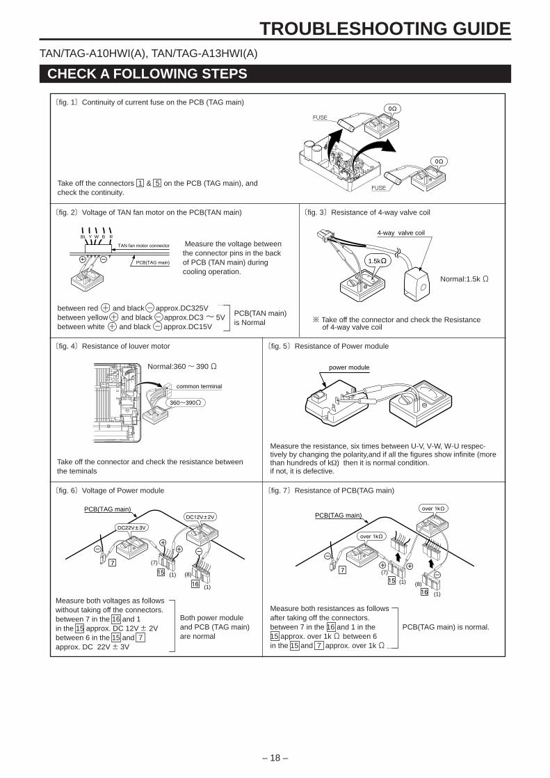
〔fig. 2〕Voltage of TAN fan motor on the PCB(TAN main)
〔fig. 1〕Continuity of current fuse on the PCB (TAG main)0Ω
0Ω
FUSE
FUSE
BL
PCB(TAG main)
TAN fan motor connector
RY BW4-way valve coil
1.5kΩ
common terminal
360~390Ω
power module
PCB(TAN main)is Normal
Measure the voltage betweenthe connector pins in the backof PCB (TAN main) duringcooling operation.
〔fig. 3〕Resistance of 4-way valve coil
〔fig. 4〕Resistance of louver motor 〔fig. 5〕Resistance of Power module
Normal:1.5kΩ
※ Take off the connector and check the Resistance of 4-way valve coil
Normal:360~ 390Ω
Take off the connector and check the resistance betweenthe teminals
Measure the resistance, six times between U-V, V-W, W-U respec-tively by changing the polarity,and if all the figures show infinite (morethan hundreds of kΩ) then it is normal condition.if not, it is defective.
Take off the connectors 1 & 5 on the PCB (TAG main), andcheck the continuity.
between red + and black - approx.DC325Vbetween yellow + and black - approx.DC3~ 5Vbetween white + and black - approx.DC15V
PCB(TAG main)
15
16
DC12V±2V
+ + -
DC22V±3V
7
-
(1)
(1)
(7)
(8)
PCB(TAG main)
15
7
16
-
+ +
-
(1)
(1)
(7)
(8)
over 1kΩ
over 1kΩ
〔fig. 6〕Voltage of Power module 〔fig. 7〕Resistance of PCB(TAG main)
Measure both voltages as followswithout taking off the connectors.between 7 in the 16 and 1in the 15 approx. DC 12V± 2Vbetween 6 in the 15 and 7approx. DC 22V± 3V
Measure both resistances as followsafter taking off the connectors.between 7 in the 16 and 1 in the15 approx. over 1kΩ between 6in the 15 and 7 approx. over 1kΩ
PCB(TAG main) is normal.Both power moduleand PCB (TAG main)are normal
TAN/TAG-A10HWI(A), TAN/TAG-A13HWI(A)
– 19 –
TROUBLESHOOTING GUIDE
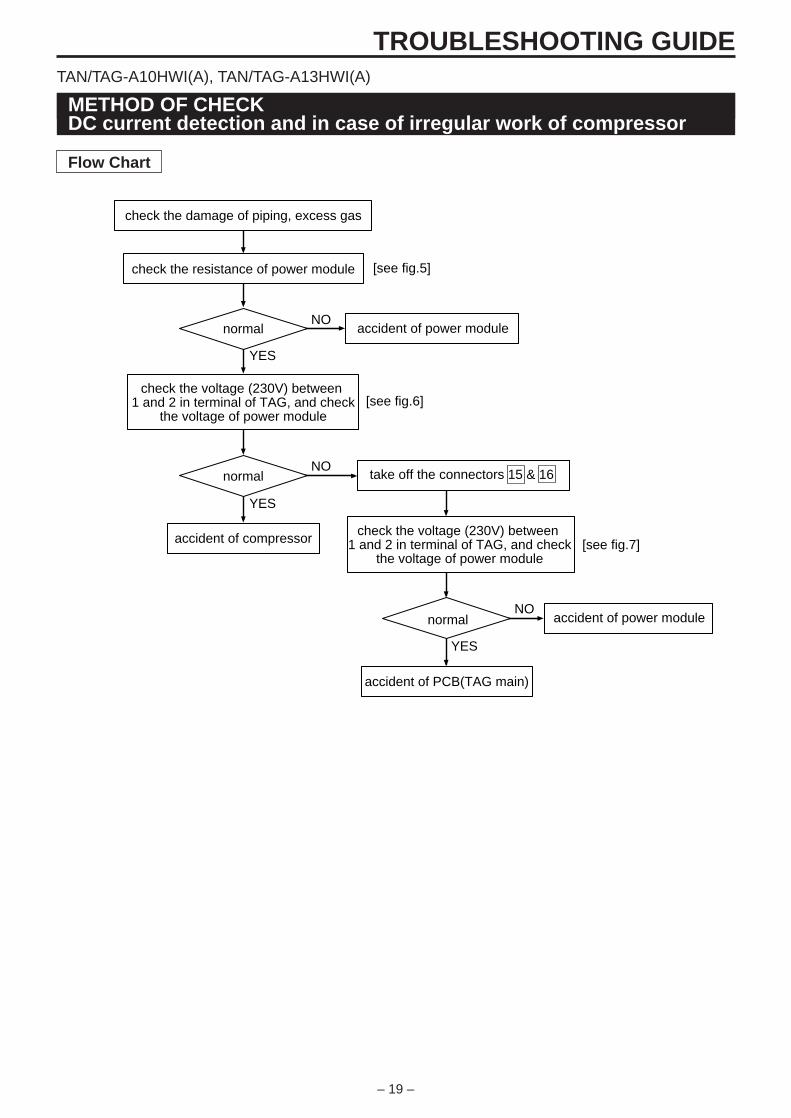
METHOD OF CHECKDC current detection and in case of irregular work of compressor
check the damage of piping, excess gas
check the resistance of power module [see fig.5]
[see fig.6]
[see fig.7]
normal
accident of compressor
accident of PCB(TAG main)
accident of power module
take off the connectors 15 & 16normal
normal
NO
NO
YES
YES
accident of power module
check the voltage (230V) between 1 and 2 in terminal of TAG, and check
the voltage of power module
check the voltage (230V) between 1 and 2 in terminal of TAG, and check
the voltage of power module
NO
YES
Flow Chart
TAN/TAG-A10HWI(A), TAN/TAG-A13HWI(A)
– 20 –
TROUBLESHOOTING GUIDE
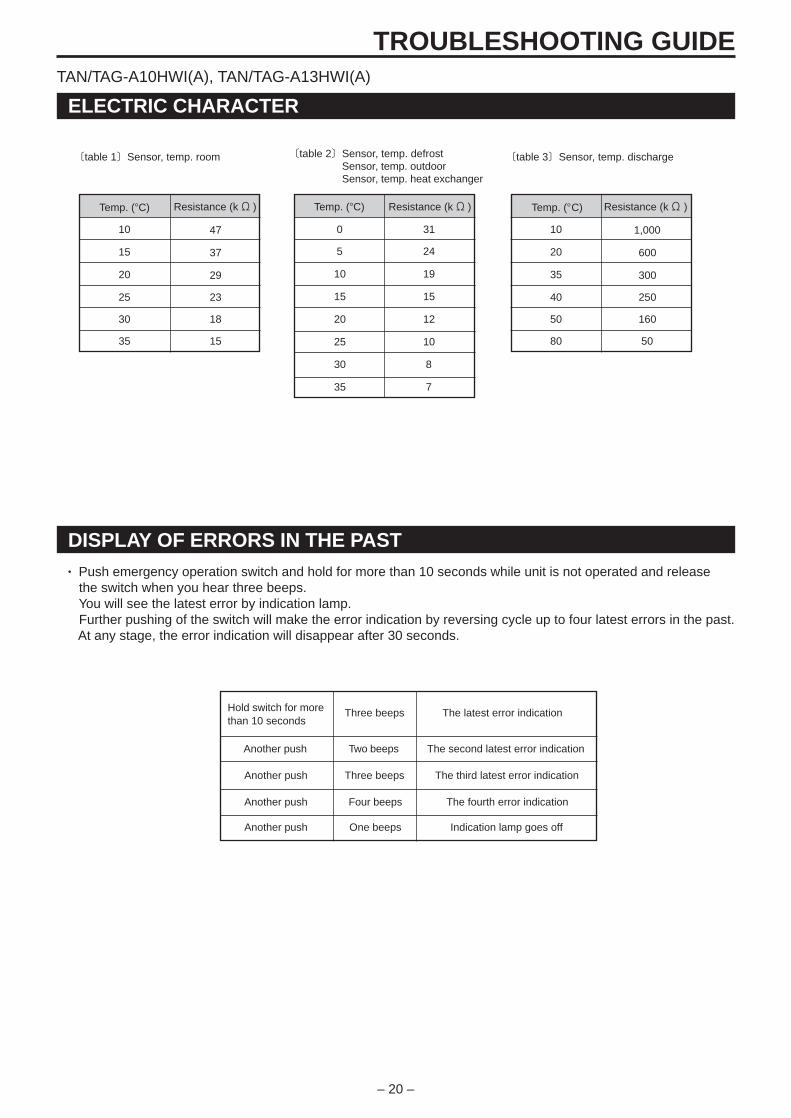
DISPLAY OF ERRORS IN THE PAST
Hold switch for morethan 10 seconds
Another push
Three beeps The latest error indication
Another push
Another push
Another push
Four beeps
Three beeps
Two beeps
One beeps
The second latest error indication
The fourth error indication
The third latest error indication
Indication lamp goes off
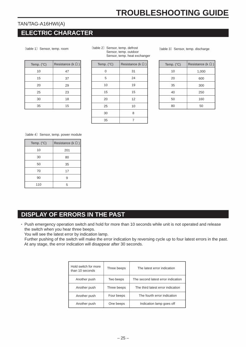
ELECTRIC CHARACTER
〔table 1〕Sensor, temp. room 〔table 2〕Sensor, temp. defrostSensor, temp. outdoorSensor, temp. heat exchanger
〔table 3〕Sensor, temp. discharge
• Push emergency operation switch and hold for more than 10 seconds while unit is not operated and release the switch when you hear three beeps. You will see the latest error by indication lamp. Further pushing of the switch will make the error indication by reversing cycle up to four latest errors in the past. At any stage, the error indication will disappear after 30 seconds.
47
37
29
23
18
15
Resistance (kΩ )
10
15
20
25
30
35
Temp. (°C) Resistance (kΩ )
0
5
10
15
20
25
30
35
Temp. (°C)
31
24
19
15
12
10
8
7
1,000
600
300
250
160
50
Resistance (kΩ )
10
20
35
40
50
80
Temp. (°C)
TAN/TAG-A10HWI(A), TAN/TAG-A13HWI(A)
– 21 –
TROUBLESHOOTING GUIDE
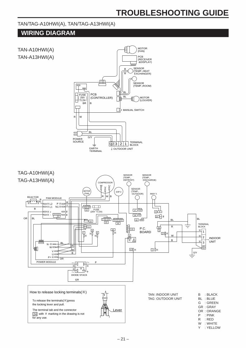
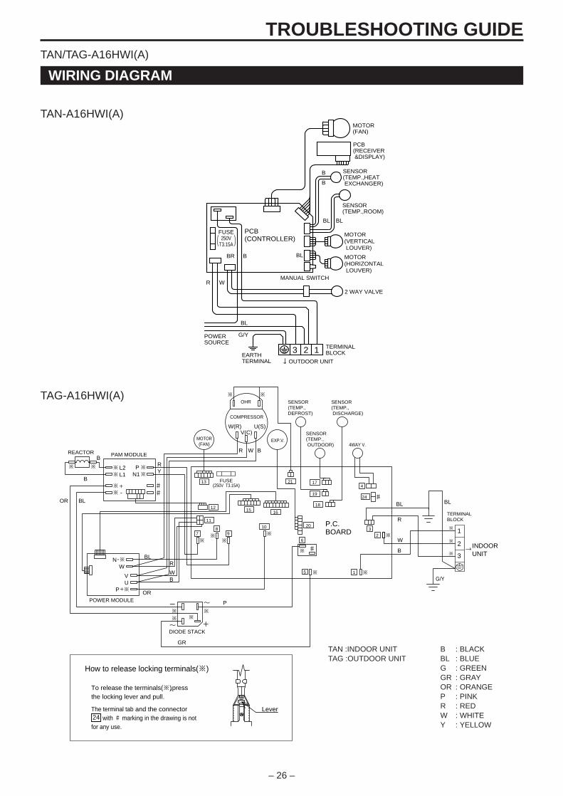
WIRING DIAGRAM
TAN :INDOOR UNITTAG :OUTDOOR UNIT
BBLGGRORPRWY
: BLACK: BLUE: GREEN: GRAY: ORANGE: PINK: RED: WHITE: YELLOW
-
~ +
~
3
5
W
BL BL
※
POWER MODULE
P.C.BOARD
R W B
R
WB
※
※ ※
※
※ ※
※
※
※
※
EXP.V.
4
6
B
BRY
OR BL
P
L2L1
+-
PN1
NW
P
VU
※ ※
※ ※
※ ※
VU
※
※ 9
※
8
※ 7
※
1
2
24
20
1615
11
10
12
13
19
17
18
3
1
2
4WAY V.
SENSOR(TEMP., DISCHARGE)
SENSOR(TEMP., OUTDOOR)
TERMINALBLOCK
INDOORUNIT
SENSOR(TEMP.,DEFROST)
PAM MODULE
DIODE STACK
COMPRESSOR
REACTOR
♯ W
R
B
♯ ♯
G/Y
※
※
※
FUSE(250V T3.15A)
GR
BL
OR
MOTOR(FAN)
♯
How to release locking terminals(※)
To release the terminals(※) ,pressthe locking lever and pull.
LeverThe terminal tab and the connector with ♯ marking in the drawing is notfor any use.24
+
-
G/Y
EARTHTERMINAL
SENSOR(TEMP.,HEAT EXCHANGER)
SENSOR(TEMP.,ROOM)
MOTOR(FAN)
PCB(RECEIVER &DISPLAY)
MANUAL SWITCH
TERMINALBLOCK
FUSE250V
T3.15A
PCB(CONTROLLER)
POWERSOURCE
3 2 1OUTDOOR UNIT
B
R W
BR B
B
BL
BL
BL
MOTOR(LOUVER)
TAN/TAG-A10HWI(A), TAN/TAG-A13HWI(A)
TAN-A10HWI(A)
TAN-A13HWI(A)
TAG-A10HWI(A)
TAG-A13HWI(A)
– 22 –
TROUBLESHOOTING GUIDE
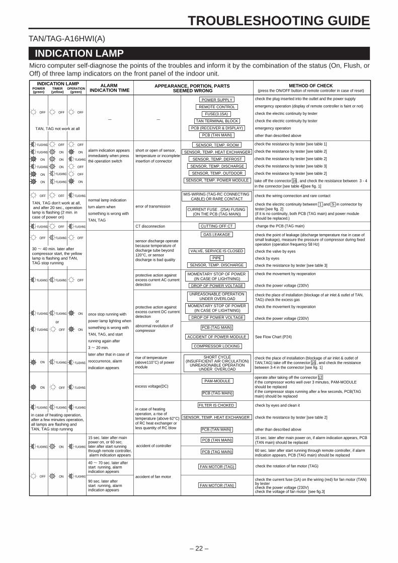
INDICATION LAMP
ALARM INDICATION TIME
APPEARANCE, PORTION, PARTS SEEMED WRONG
MOMENTARY STOP OF POWER (IN CASE OF LIGHTNING)
DROP OF POWER VOLTAGE
check the plug inserted into the outlet and the power supply
emergency operation (display of remote controller is faint or not)
check the electric continuity by tester
check the electric continuity by tester
emergency operation
other than described above
15 sec. later after main power on, if alarm indication appears, PCB (TAN main) should be replaced
check the current fuse (1A) on the wiring (red) for fan motor (TAN) by testercheck the power voltage (230V)check the voltage of fan motor [see fig.3]
METHOD OF CHECK(press the ON/OFF button of remote controller in case of reset)POWER
(green)TIMER
(yellow)OPERATION
(green)
INDICATION LAMP
OFF OFF OFF
TAN, TAG not work at all
FLASHING OFF OFF
FLASHING ON ON
ON
ON ON FLASHING
FLASHING ON OFF
OFF
alarm indication appears immediately when press the operation switch
OFF OFF FLASHING
FLASHING OFF FLASHING
TAN, TAG don’t work at all, and after 20 sec., operation lamp is flashing (2 min. in case of power on)
normal lamp indication
turn alarm when
something is wrong with
TAN, TAG
error of transmission
CT disconnection
OFF FLASHING OFF
FLASHING FLASHING OFF
OFF
or
OFF
30 ~ 40 min. later after compressor start, the yellow lamp is flashing and TAN, TAG stop running
sensor discharge operate because temperature of discharge tube beyond 120°C, or sensor discharge is bad quality
protective action against excess current AC current detection
FLASHING FLASHING ON
FLASHING
FLASHING
FLASHING
ON
FLASHING
FLASHING
once stop running with
power lamp lighting when
something is wrong with
TAN, TAG, and start
running again after
3 ~ 20 min.
later after that in case of
reoccurrence, alarm
indication appears
protective action against excess current DC current detection orabnormal revolution of compressor
rise of temperature(above110°C) of powermodule
excess voltage(DC)
in case of heating operation, a rise of temperature (above 62°C) of RC heat exchanger or less quantity of RC blow
FLASHING FLASHING
OFF
FLASHING ON
ON
FLASHING
FLASHING
in case of heating operation, after a few minutes operation, all lamps are flashing and TAN, TAG stop running
15 sec. later after main power on, or 60 sec. later after start running through remote controller, alarm indication appears
40 ~ 70 sec. later after start running, alarm indication appears
90 sec. later after start running, alarm indication appears
accident of controller
accident of fan motor
short or open of sensor, temperature or incomplete insertion of connector
PCB (TAN MAIN)
PCB (TAG MAIN)
FAN MOTOR (TAG)
FAN MOTOR (TAN)
SENSOR, TEMP. ROOM
SENSOR, TEMP. HEAT EXCHANGER
SENSOR, TEMP. DEFROST
SENSOR, TEMP. DISCHARGE
SENSOR, TEMP. OUTDOOR
SENSOR, TEMP. POWER MODULE
FILTER IS CHOKED
SENSOR, TEMP. HEAT EXCHANGER
PCB (TAN MAIN)
UNREASONABLE OPERATION UNDER OVERLOAD
MOMENTARY STOP OF POWER (IN CASE OF LIGHTNING)
DROP OF POWER VOLTAGE
PCB (TAG MAIN)
ACCIDENT OF POWER MODULE
COMPRESSOR LOCKING
POWER SUPPLY
REMOTE CONTROL
FUSE(3.15A)
TAN TERMINAL BLOCK
PCB (RECEIVER & DISPLAY)
PCB (TAN MAIN)
MIS-WIRING (TAG-RC CONNECTING CABLE) OR RARE CONTACT
CUTTING OFF CT
CURRENT FUSE . (25A) FUSING (ON THE PCB (TAG MAIN))
GAS LEAKAGE
VALVE, SERVICE IS CLOSED
PIPE
SENSOR, TEMP. DISCHARGE
check the place of installation (blockage of air inlet & outlet of TAN, TAG) check the excess gas
check the movement by reoperation
check the power voltage (230V)
check the place of installation (blockage of air inlet & outlet of TAN,TAG) take off the connector 16 , and check the resistance between 3-4 in the connector [see fig. 1]
operate after taking off the connector 12if the compressor works well over 3 minutes, PAM-MODULE should be replaced if the compressor stops running after a few seconds, PCB(TAG main) should be replaced
check by eyes and clean it
check the resistance by tester [see table 2]
other than described above
check the movement by reoperation
check the power voltage (230V)
See Flow Chart (P24)
change the PCB (TAG main)
check the wiring connection and rare contact
check the resistance by tester [see table 1]
check the resistance by tester [see table 2]
check the resistance by tester [see table 2]
check the resistance by tester [see table 3]
check the resistance by tester [see table 2]
take off the connector 16 , and check the resistance between 3 - 4in the connector [see table 4][see fig. 1]
check the point of leakage (discharge temperature rise in case of small leakage), measure the pressure of compressor during fixed operation (operation frequency 58 Hz)
check the valve by eyes
check by eyes
check the resistance by tester [see table 3]
check the electric continuity between 1 and 5 in connector by tester.[see fig. 2](if it is no continuity, both PCB (TAG main) and power module should be replaced.)
ON
ON
FLASHING
FLASHING
ON
ON
check the rotation of fan motor (TAG)
60 sec. later after start running through remote controller, if alarm indication appears, PCB (TAG main) should be replaced
- -
PAM-MODULE
PCB (TAG MAIN)
SHORT CYCLE(INSUFFICIENT AIR CIRCULATION)
UNREASONABLE OPERATIONUNDER OVERLOAD
Micro computer self-diagnose the points of the troubles and inform it by the combination of the status (On, Flush, orOff) of three lamp indicators on the front panel of the indoor unit.
TAN/TAG-A16HWI(A)
– 23 –
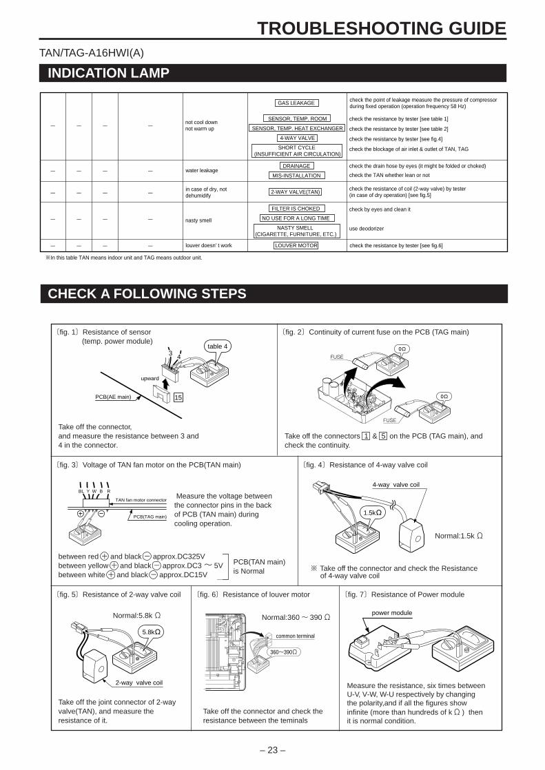
TROUBLESHOOTING GUIDE
INDICATION LAMP
check the drain hose by eyes (it might be folded or choked)
check the TAN whether lean or not
check the resistance of coil (2-way valve) by tester(in case of dry operation) [see fig.5]
not cool downnot warm up
water leakage
in case of dry, not dehumidify
louver doesn' t work check the resistance by tester [see fig.6]
check the point of leakage measure the pressure of compressor during fixed operation (operation frequency 58 Hz)
nasty smell
FILTER IS CHOKED
NO USE FOR A LONG TIME
NASTY SMELL (CIGARETTE, FURNITURE, ETC.)
DRAINAGE
MIS-INSTALLATION
LOUVER MOTOR
GAS LEAKAGE
2-WAY VALVE(TAN)
SENSOR, TEMP. ROOM
SENSOR, TEMP. HEAT EXCHANGER
4-WAY VALVE
SHORT CYCLE (INSUFFICIENT AIR CIRCULATION)
check by eyes and clean it
use deodorizer
check the resistance by tester [see table 1]
check the resistance by tester [see table 2]
check the resistance by tester [see fig.4]
check the blockage of air inlet & outlet of TAN, TAG
- - - -
- - - -
- - - -
- - - -
- - - -
※In this table TAN means indoor unit and TAG means outdoor unit.
CHECK A FOLLOWING STEPS
〔fig. 3〕Voltage of TAN fan motor on the PCB(TAN main)
〔fig. 1〕Resistance of sensor (temp. power module)
〔fig. 2〕Continuity of current fuse on the PCB (TAG main)
Take off the connector,and measure the resistance between 3 and4 in the connector.
table 4
15
3 4
upward
PCB(AE main)
0Ω
0Ω
FUSE
FUSE
BL
PCB(TAG main)
TAN fan motor connector
RY BW4-way valve coil
1.5kΩ
2-way valve coil
5.8kΩ common terminal
360~390Ω
power module
PCB(TAN main)is Normal
Measure the voltage betweenthe connector pins in the backof PCB (TAN main) duringcooling operation.
〔fig. 4〕Resistance of 4-way valve coil
〔fig. 5〕Resistance of 2-way valve coil 〔fig. 6〕Resistance of louver motor 〔fig. 7〕Resistance of Power module
Normal:1.5kΩ
※ Take off the connector and check the Resistance of 4-way valve coil
Take off the joint connector of 2-wayvalve(TAN), and measure theresistance of it.
Normal:360~ 390Ω
Take off the connector and check theresistance between the teminals
Measure the resistance, six times betweenU-V, V-W, W-U respectively by changingthe polarity,and if all the figures showinfinite (more than hundreds of kΩ ) thenit is normal condition.
Normal:5.8kΩ
Take off the connectors 1 & 5 on the PCB (TAG main), andcheck the continuity.
between red + and black - approx.DC325Vbetween yellow + and black - approx.DC3~ 5Vbetween white + and black - approx.DC15V
TAN/TAG-A16HWI(A)
– 24 –
TROUBLESHOOTING GUIDE
PCB(TAG main)
15
16
DC12V±2V
+ + -
DC22V±3V
7
-
(1)
(1)
(7)
(8)
PCB(TAG main)
15
7
16
-
+ +
-
(1)
(1)
(7)
(8)
over 1kΩ
over 1kΩ
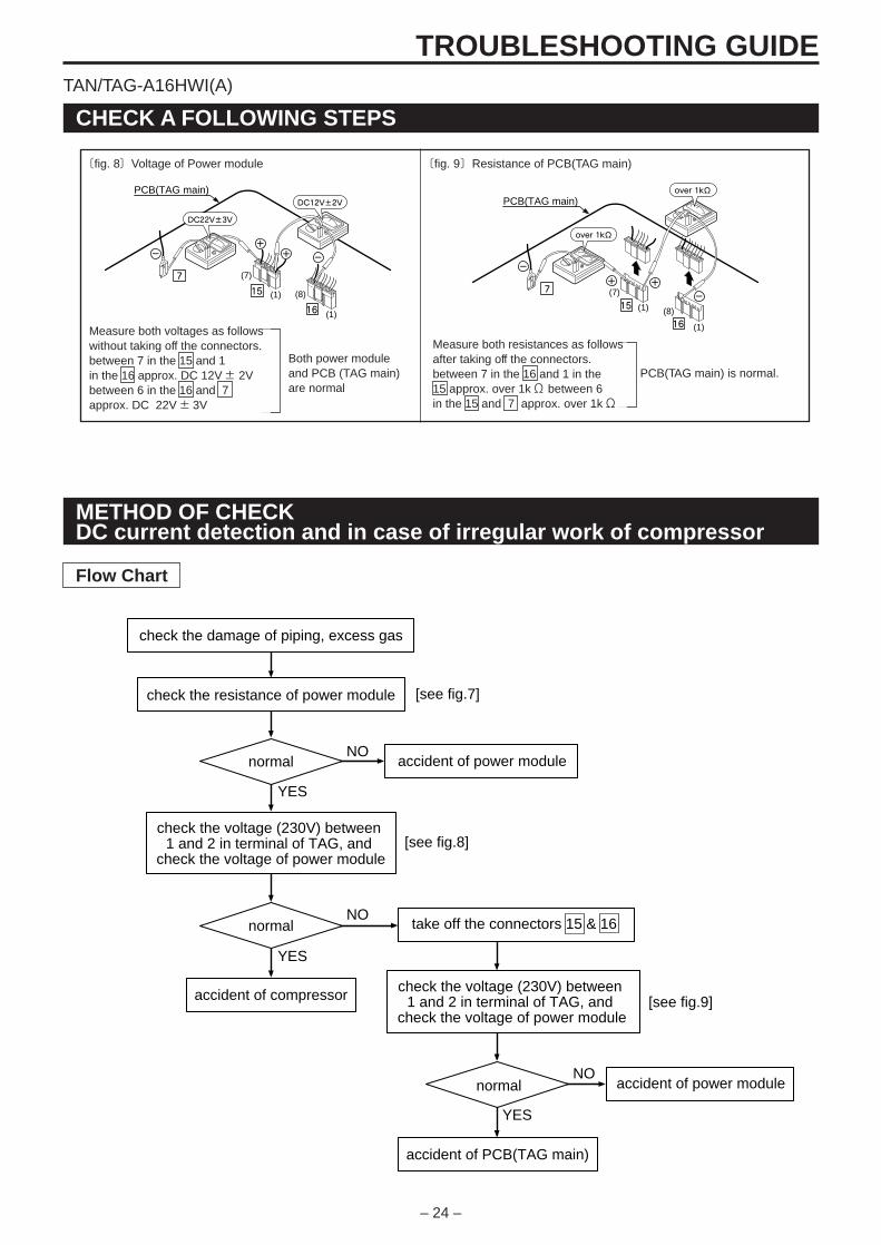
〔fig. 8〕Voltage of Power module 〔fig. 9〕Resistance of PCB(TAG main)
CHECK A FOLLOWING STEPS
Both power moduleand PCB (TAG main)are normal
Measure both voltages as followswithout taking off the connectors.between 7 in the 15 and 1in the 16 approx. DC 12V± 2Vbetween 6 in the 16 and 7approx. DC 22V± 3V
METHOD OF CHECKDC current detection and in case of irregular work of compressor
check the damage of piping, excess gas
check the resistance of power module [see fig.7]
[see fig.8]
[see fig.9]
normal
accident of compressor
accident of PCB(TAG main)
accident of power module
take off the connectors 15 & 16normal
normal
NO
NO
YES
YES
accident of power module
check the voltage (230V) between 1 and 2 in terminal of TAG, and
check the voltage of power module
check the voltage (230V) between 1 and 2 in terminal of TAG, and
check the voltage of power module
NO
YES
Flow Chart
TAN/TAG-A16HWI(A)
Measure both resistances as followsafter taking off the connectors.between 7 in the 16 and 1 in the15 approx. over 1kΩ between 6in the 15 and 7 approx. over 1kΩ
PCB(TAG main) is normal.
– 25 –
TROUBLESHOOTING GUIDE
DISPLAY OF ERRORS IN THE PAST
Hold switch for morethan 10 seconds
Another push
Three beeps The latest error indication
Another push
Another push
Another push
Four beeps
Three beeps
Two beeps
One beeps
The second latest error indication
The fourth error indication
The third latest error indication
Indication lamp goes off
ELECTRIC CHARACTER
〔table 1〕Sensor, temp. room 〔table 2〕Sensor, temp. defrostSensor, temp. outdoorSensor, temp. heat exchanger
〔table 3〕Sensor, temp. discharge
〔table 4〕Sensor, temp. power module
• Push emergency operation switch and hold for more than 10 seconds while unit is not operated and release the switch when you hear three beeps. You will see the latest error by indication lamp. Further pushing of the switch will make the error indication by reversing cycle up to four latest errors in the past. At any stage, the error indication will disappear after 30 seconds.
47
37
29
23
18
15
Resistance (kΩ )
10
15
20
25
30
35
Temp. (°C) Resistance (kΩ )
0
5
10
15
20
25
30
35
Temp. (°C)
31
24
19
15
12
10
8
7
1,000
600
300
250
160
50
Resistance (kΩ )
10
20
35
40
50
80
Temp. (°C)
201
80
35
17
9
5
Resistance (kΩ )
10
30
50
70
90
110
Temp. (°C)
TAN/TAG-A16HWI(A)
– 26 –
TROUBLESHOOTING GUIDE
-
~ +
~
3
5
W(R)
BL BL
※
POWER MODULE
P.C.BOARD
R W B
R
WB
※
※ ※
※
※ ※
※
※
※
※
EXP.V.
4
6
B
BRY
OR BL
P
L2L1
+-
PN1
NW
P
VU
※ ※
※ ※
※ ※
V(C)U(S)
※
※ ※
※ 9
※
8
※ 7
※
1
2
24
20
1615
11
10
12
13
19
1721
18
3
1
2
4WAY V.
SENSOR(TEMP., DISCHARGE)
SENSOR(TEMP., OUTDOOR)
TERMINALBLOCK
INDOORUNIT
SENSOR(TEMP.,DEFROST)
PAM MODULE
DIODE STACK
COMPRESSOR
OHR
REACTOR
♯ W
R
B
♯ ♯
G/Y
※
※
※
FUSE(250V T3.15A)
GR
BL
OR
MOTOR(FAN)
♯
How to release locking terminals(※)
Lever
To release the terminals(※) ,pressthe locking lever and pull.
The terminal tab and the connector with ♯ marking in the drawing is notfor any use.
24
+
-
WIRING DIAGRAM
TAN/TAG-A16HWI(A)
TAN-A16HWI(A)
TAG-A16HWI(A)
G/Y
EARTHTERMINAL
SENSOR(TEMP.,HEAT EXCHANGER)
SENSOR(TEMP.,ROOM)
MOTOR(FAN)
PCB(RECEIVER &DISPLAY)
MANUAL SWITCH
TERMINALBLOCK
FUSE250V
T3.15A
PCB(CONTROLLER)
POWERSOURCE
3 2 1OUTDOOR UNIT
B
R W
BR B
B
BLBL
BL
BL
MOTOR(VERTICAL LOUVER)
MOTOR(HORIZONTAL LOUVER)
2 WAY VALVE
TAN :INDOOR UNITTAG :OUTDOOR UNIT
BBLGGRORPRWY
: BLACK: BLUE: GREEN: GRAY: ORANGE: PINK: RED: WHITE: YELLOW
– 27 –
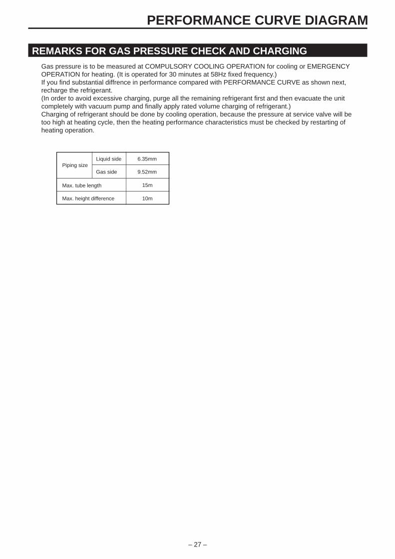
PERFORMANCE CURVE DIAGRAM
REMARKS FOR GAS PRESSURE CHECK AND CHARGINGGas pressure is to be measured at COMPULSORY COOLING OPERATION for cooling or EMERGENCYOPERATION for heating. (It is operated for 30 minutes at 58Hz fixed frequency.)If you find substantial diffrence in performance compared with PERFORMANCE CURVE as shown next,recharge the refrigerant.(In order to avoid excessive charging, purge all the remaining refrigerant first and then evacuate the unitcompletely with vacuum pump and finally apply rated volume charging of refrigerant.)Charging of refrigerant should be done by cooling operation, because the pressure at service valve will betoo high at heating cycle, then the heating performance characteristics must be checked by restarting ofheating operation.
Piping size
Max. tube length
Liquid side
Gas side
Max. height difference
6.35mm
9.52mm
15m
10m
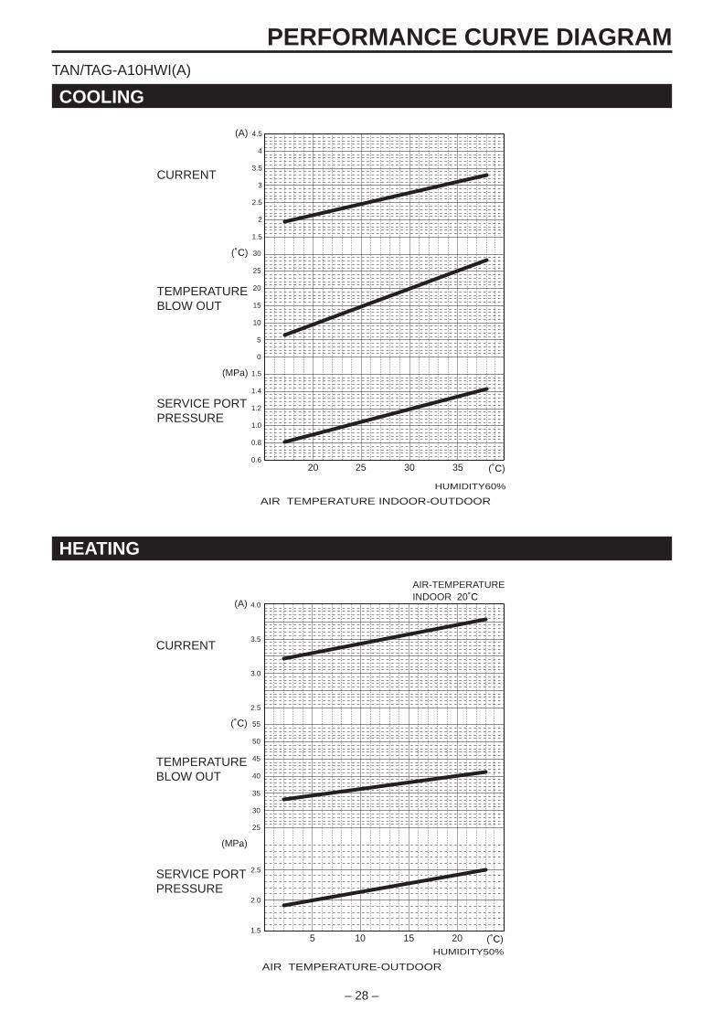
– 28 –
PERFORMANCE CURVE DIAGRAM
HEATING
COOLING
TAN/TAG-A10HWI(A)
0.6
0.8
1.0
1.2
1.4
1.5
SERVICE PORTPRESSURE
(A)
(˚C)
(MPa)
1.5
2
2.5
3
3.5
4
4.5
CURRENT
TEMPERATURE BLOW OUT
AIR TEMPERATURE INDOOR-OUTDOOR
HUMIDITY60%
0
5
10
15
20
25
30
20 25 30 35 (˚C)
5 10 15 20
AIR TEMPERATURE-OUTDOOR
HUMIDITY50%
(˚C)
AIR-TEMPERATUREINDOOR 20˚C
1.5
2.0
2.5
25
30
35
40
45
50
55(˚C)
(MPa)
CURRENT
TEMPERATURE BLOW OUT
SERVICE PORTPRESSURE
2.5
3.0
3.5
4.0(A)

– 29 –
PERFORMANCE CURVE DIAGRAM
HEATING
COOLING
TAN/TAG-A13HWI(A)
0.6
0.8
1.0
1.2
1.4
1.6
SERVICE PORTPRESSURE
(A)
(˚C)
(MPa)
2.5
3
3.5
2
4
4.5
5
CURRENT
TEMPERATURE BLOW OUT
AIR TEMPERATURE INDOOR-OUTDOOR
HUMIDITY60%
0
5
10
15
20
25
30
20 25 30 35 (˚C)
5 10 15 20
AIR TEMPERATURE-OUTDOOR
HUMIDITY50%
(˚C)
AIR-TEMPERATUREINDOOR 20˚C
2.0
2.5
3.0
30
35
40
45
50
55
60(˚C)
(MPa)
CURRENT
TEMPERATURE BLOW OUT
SERVICE PORTPRESSURE
4
5
6
7(A)

– 30 –
PERFORMANCE CURVE DIAGRAM
HEATING
COOLING
TAN/TAG-A16HWI(A)
0.7
0.8
0.9
1.0
1.1
1.2
SERVICE PORTPRESSURE
(A)
(˚C)
(MPa)
3.5
4
4.5
5
5.5
6
6.5
CURRENT
TEMPERATURE BLOW OUT
AIR TEMPERATURE INDOOR-OUTDOOR
HUMIDITY60%
0
5
10
15
20
25
30
20 25 30 35 (˚C)
5 10 15 20
AIR TEMPERATURE-OUTDOOR
HUMIDITY50%
(˚C)
AIR-TEMPERATUREINDOOR 20˚C
2.0
2.5
3.0
30
35
40
45
50
55
60(˚C)
(MPa)
CURRENT
TEMPERATURE BLOW OUT
SERVICE PORTPRESSURE
4
5
6
7(A)
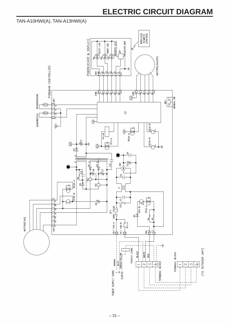
– 31 –
ELECTRIC CIRCUIT DIAGRAMTAN-A10HWI(A), TAN-A13HWI(A)
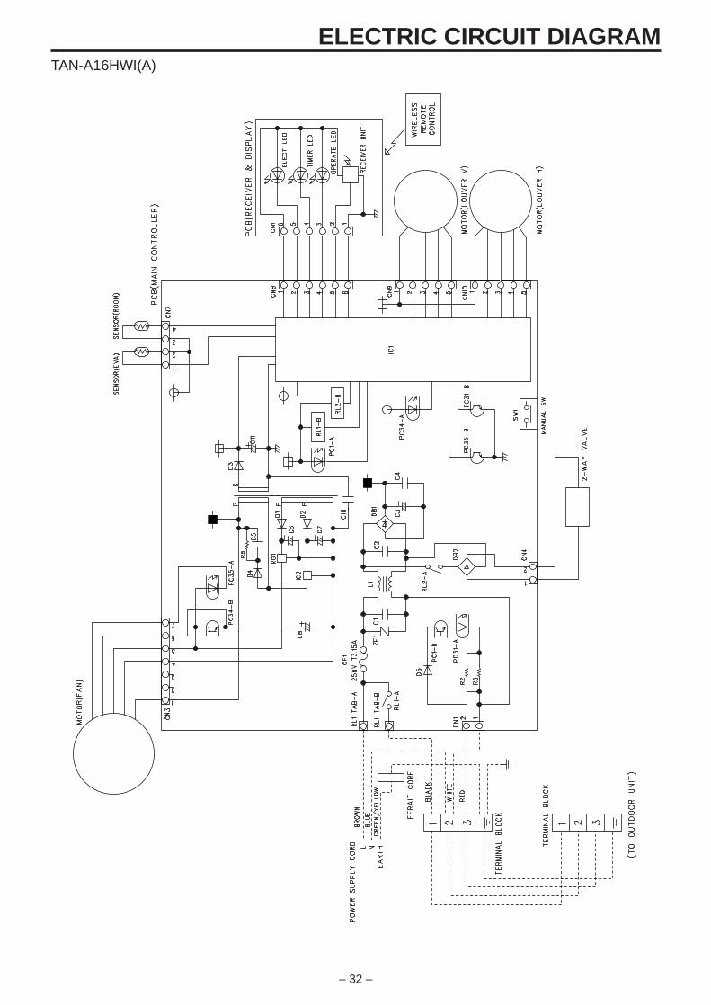
– 32 –
ELECTRIC CIRCUIT DIAGRAMTAN-A16HWI(A)
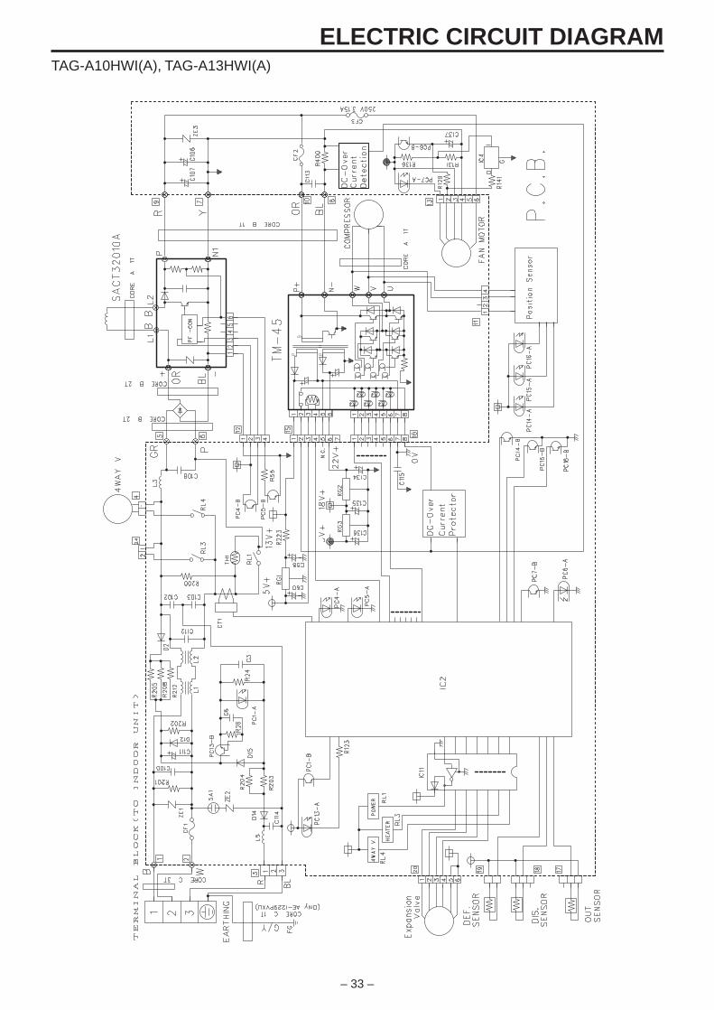
– 33 –
ELECTRIC CIRCUIT DIAGRAMTAG-A10HWI(A), TAG-A13HWI(A)
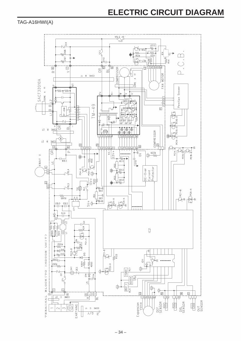
– 34 –
ELECTRIC CIRCUIT DIAGRAMTAG-A16HWI(A)
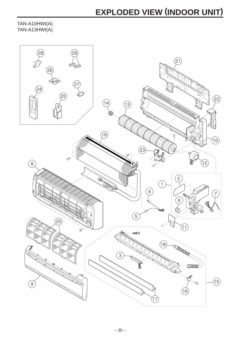
– 35 –
28
26
27
8
14 13
10
12
11
9
18
16
15
25
19
23
21
4
5
3
7
6
21
22
24
29
17
20
EXPLODED VIEW (INDOOR UNIT)TAN-A10HWI(A)TAN-A13HWI(A)
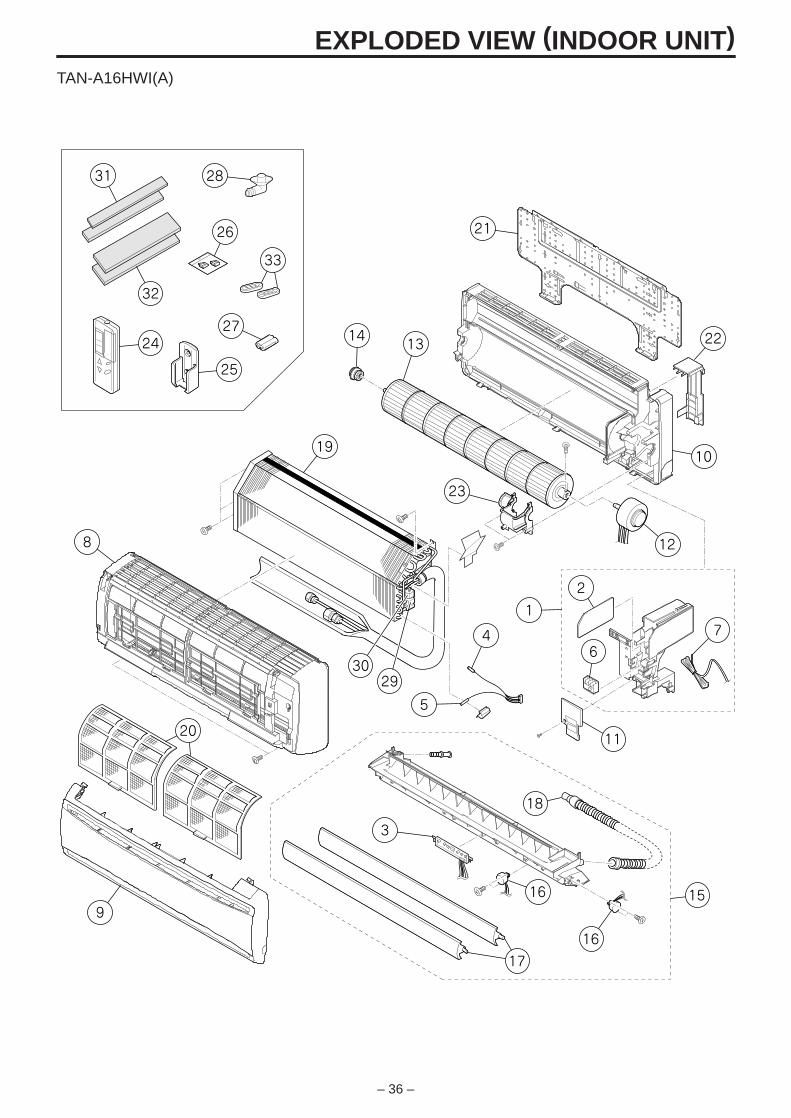
– 36 –
EXPLODED VIEW (INDOOR UNIT)TAN-A16HWI(A)
11
9
16
15
18
16
10
12
1314
6
2
1
4
23
5
3029
3
7
22
21
19
25
24
32
31
27
28
26
8
20
17
33
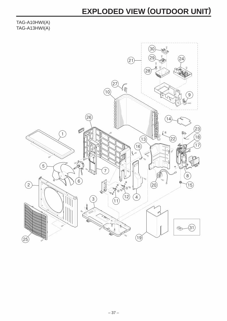
– 37 –
EXPLODED VIEW (OUTDOOR UNIT)
28
26
1
5
62
3
19
31
1112 4
16
10
13
15
8
23
14
22 18
17
20
25
24
30
29
9
21
7
27
TAG-A10HWI(A)TAG-A13HWI(A)
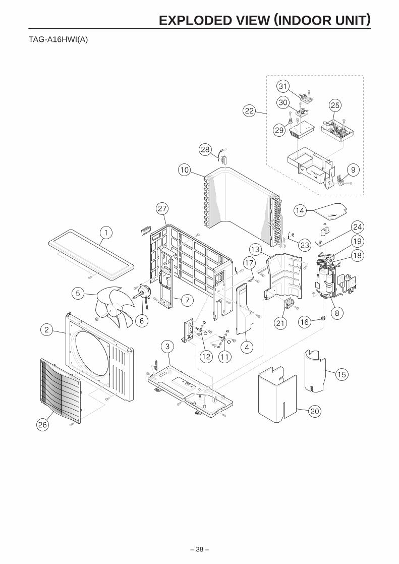
– 38 –
EXPLODED VIEW (INDOOR UNIT)TAG-A16HWI(A)
16
10
15
1112
8
9
31
3022
29
14
24
19
18
20
21
17
2313
43
26
2
5
1
27
28
6
7
25
– 39 –
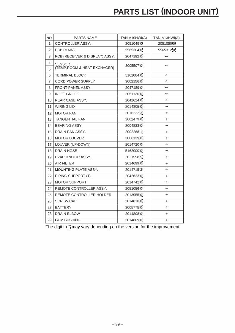
PARTS LIST (INDOOR UNIT)
NO. PARTS NAME TAN-A10HWI(A) TAN-A13HWI(A)
1 CONTROLLER ASSY. 2051049 0 2051050 0
2 PCB (MAIN) 5565304 0 5565312 0
3 PCB (RECEIVER & DISPLAY) ASSY. 2047192 0
4 SENSOR(TEMP,ROOM & HEAT EXCHAGER)
3005507 05
6 TERMINAL BLOCK 5162084 0
7 CORD,POWER SUPPLY 3002156 0
8 FRONT PANEL ASSY. 2047189 0
9 INLET GRILLE 2051130 0
10 REAR CASE ASSY. 2042624 0
11 WIRING LID 2014805 0
12 MOTOR,FAN 2016222 3
13 TANGENTIAL FAN 3002479 0
14 BEARING ASSY. 2004833 0
15 DRAIN PAN ASSY. 2002268 1
16 MOTOR,LOUVER 3006139 0
17 LOUVER (UP-DOWN) 2014720 0
18 DRAIN HOSE 5162000 0
19 EVAPORATOR ASSY. 2021598 5
20 AIR FILTER 2014699 0
21 MOUNTING PLATE ASSY. 2014715 3
22 PIPING SUPPORT (1) 2042623 0
23 MOTOR SUPPORT 2014742 0
24 REMOTE CONTROLLER ASSY. 2051056 0
25 REMOTE CONTROLLER HOLDER 2013955 0
26 SCREW CAP 2014810 0
27 BATTERY 3005775 0
28 DRAIN ELBOW 2014808 0
29 GUM BUSHING 2014809 0
The digit in may vary depending on the version for the improvement.
– 40 –
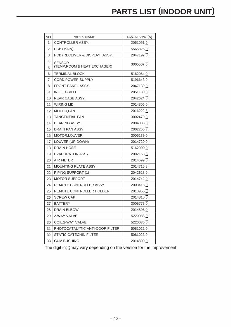
PARTS LIST (INDOOR UNIT)
NO. PARTS NAME TAN-A16HWI(A)
1 CONTROLLER ASSY. 2051051 0
2 PCB (MAIN) 5565325 0
3 PCB (RECEIVER & DISPLAY) ASSY. 2047192 0
4 SENSOR(TEMP,ROOM & HEAT EXCHAGER)
3005507 05
6 TERMINAL BLOCK 5162084 0
7 CORD,POWER SUPPLY 5196643 0
8 FRONT PANEL ASSY. 2047189 0
9 INLET GRILLE 2051130 0
10 REAR CASE ASSY. 2042624 0
11 WIRING LID 2014805 0
12 MOTOR,FAN 2016222 3
13 TANGENTIAL FAN 3002479 0
14 BEARING ASSY. 2004833 0
15 DRAIN PAN ASSY. 2002265 3
16 MOTOR,LOUVER 3006139 0
17 LOUVER (UP-DOWN) 2014720 0
18 DRAIN HOSE 5162000 0
19 EVAPORATOR ASSY. 2002153 8
20 AIR FILTER 2014699 0
21 MOUNTING PLATE ASSY. 2014715 3
22 PIPING SUPPORT (1) 2042623 0
23 MOTOR SUPPORT 2014742 0
24 REMOTE CONTROLLER ASSY. 2003413 0
25 REMOTE CONTROLLER HOLDER 2013955 0
26 SCREW CAP 2014810 0
27 BATTERY 3005775 0
30 COIL,2-WAY VALVE 5220036 0
31 PHOTOCATALYTIC ANTI-ODOR FILTER 5081022 0
32 STATIC,CATECHIN FILTER 5081023 0
33 GUM BUSHING 2014809 0
28 DRAIN ELBOW 2014808 0
29 2-WAY VALVE 5220033 0
The digit in may vary depending on the version for the improvement.
– 41 –
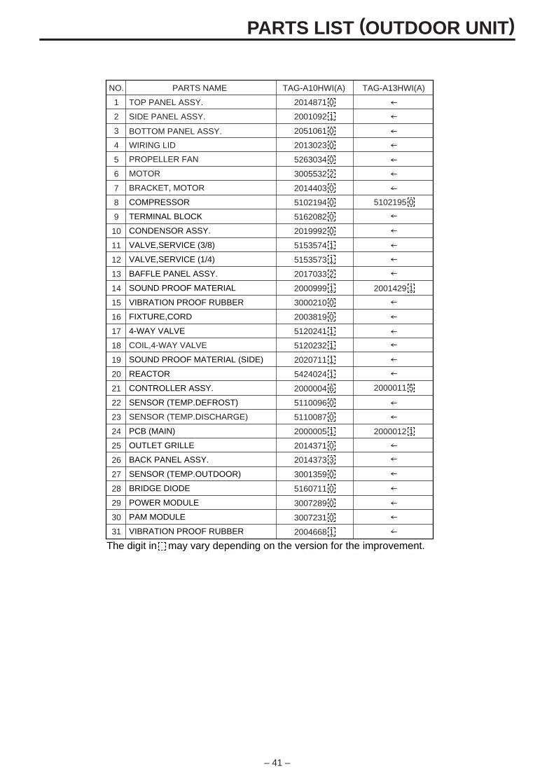
PARTS LIST (OUTDOOR UNIT)
NO. PARTS NAME TAG-A10HWI(A) TAG-A13HWI(A)
1 TOP PANEL ASSY. 2014871 0
2 SIDE PANEL ASSY. 2001092 1
3 2051061 0
4
BOTTOM PANEL ASSY.
WIRING LID 2013023 0
5 PROPELLER FAN 5263034 0
6 MOTOR 3005532 2
7 BRACKET, MOTOR 2014403 0
8 COMPRESSOR 5102194 0
9 TERMINAL BLOCK 5162082 0
5102195 0
10 CONDENSOR ASSY. 2019992 0
11 VALVE,SERVICE (3/8) 5153574 1
12 VALVE,SERVICE (1/4) 5153573 1
13 BAFFLE PANEL ASSY. 2017033 2
14 SOUND PROOF MATERIAL 2000999 1 2001429 1
15 VIBRATION PROOF RUBBER 3000210 0
16 FIXTURE,CORD 2003819 0
17 4-WAY VALVE 5120241 1
18 COIL,4-WAY VALVE 5120232 1
19 SOUND PROOF MATERIAL (SIDE) 2020711 1
2000011 5
20 REACTOR 5424024 1
21 CONTROLLER ASSY. 2000004 6
22 SENSOR (TEMP.DEFROST) 5110096 0
23 SENSOR (TEMP.DISCHARGE) 5110087 0
24 PCB (MAIN) 2000005 1 2000012 1
25 OUTLET GRILLE 2014371 0
26 BACK PANEL ASSY.
27 SENSOR (TEMP.OUTDOOR) 3001359 0
2014373 3
28 BRIDGE DIODE 5160711 0
3007231 0
3007289 0
2004668 1
29 POWER MODULE
30 PAM MODULE
31 VIBRATION PROOF RUBBER
The digit in may vary depending on the version for the improvement.
– 42 –
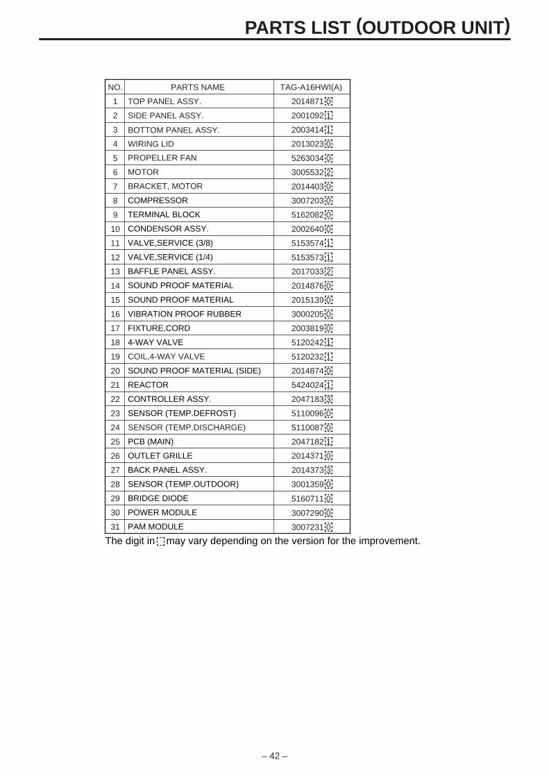
PARTS LIST (OUTDOOR UNIT)
NO. PARTS NAME TAG-A16HWI(A)
1 TOP PANEL ASSY. 2014871 0
2 SIDE PANEL ASSY. 2001092 1
3 2003414 1
4
BOTTOM PANEL ASSY.
WIRING LID 2013023 0
5 PROPELLER FAN 5263034 0
6 MOTOR 3005532 2
7 BRACKET, MOTOR 2014403 0
8 COMPRESSOR 3007203 0
9 TERMINAL BLOCK 5162082 0
10 CONDENSOR ASSY. 2002640 0
11 VALVE,SERVICE (3/8) 5153574 1
12 VALVE,SERVICE (1/4) 5153573 1
13 BAFFLE PANEL ASSY. 2017033 2
14 SOUND PROOF MATERIAL
SOUND PROOF MATERIAL
2014876 0
15
VIBRATION PROOF RUBBER
2015139 0
16
FIXTURE,CORD
3000205 0
17
4-WAY VALVE
2003819 0
18
COIL,4-WAY VALVE
5120242 1
19
SOUND PROOF MATERIAL (SIDE)
5120232 1
20
REACTOR
2014874 0
21
CONTROLLER ASSY.
5424024 1
22
SENSOR (TEMP.DEFROST)
2047183 3
23
SENSOR (TEMP.DISCHARGE)
5110096 0
24
PCB (MAIN)
5110087 0
25
OUTLET GRILLE
2047182 1
26
BACK PANEL ASSY.27
SENSOR (TEMP.OUTDOOR)
2014373 3
2014371 0
28
BRIDGE DIODE
3001359 0
3007290 0
5160711 0
3007231 0
29
POWER MODULE30
PAM MODULE31
The digit in may vary depending on the version for the improvement.
ISSUED MAY.2007
RA-58-[1]
Printed in Japan
REVISED