Embed Size (px)
Citation preview

Advanced Software for Roof and Wall Modelling and Material Estimating
Roof Wizard
Incorporating: all roof systems, labour and materials, wall cladding and trim
Learning Guide
For metric and English units Document Version v8.1 – 1.2 – 14 April 2016

AppliCad – Roof Wizard – Learning Guide V8.1
PAGE 2
AppliCad – Roof Wizard – Learning Guide V8.1
PAGE 3
SECTION 1 – INTRODUCTION ............................................................................... 11
SECTION 2A – LEARNING GUIDE (METRIC UNITS) ............................................ 13
The Learning Guide ...................................................................................................................... 13 The AppliCad Process .................................................................................................................. 13 Roof Creation and Modification .................................................................................................... 13
Exercise 1 - Track Outline ............................................................................................... 14 Save Your Job .......................................................................................................................... 18
Exercise 2 - Track Outline ................................................................................................ 20
Exercise 3 - Track Outline – (using Angles) ..................................................................... 21 CHECKING YOUR JOB – THE APPLICAD PROCESS ................................................................................ 23
Exercise 4 - Track Outline – (Single Slope Roofs) ............................................................ 25
Exercise 5 - Track Outline (for Single Slope Roofs) .......................................................... 27
Exercise 6 - Track Outline (for Single Slope Roofs) .......................................................... 27
Exercise 7 - Gable Roofs ................................................................................................... 29
Exercise 8 - Adding a Verandah ......................................................................................... 31
Exercise 9 - Adding a Verandah II ...................................................................................... 33 Exercise 10 - More Track-Outline Examples ............................................................................... 34
Exercise 11 - Track Outline ............................................................................................... 36 THE MODIFY ROOF COMMAND ............................................................................................................. 37
Exercise 12 - Modify Roof > Atrium ................................................................................. 38
Exercise 13 - Modify Roof > Valley-Gable ......................................................................... 38
Exercise 14 - Modify Roof > Gable To Hip ....................................................................... 40
Exercise 15 - Modify Roof > Dutch Gable ........................................................................ 40
Exercise 16 - Modify Roof > Flying Gable ........................................................................ 41
Exercise 17 - Modify Roof > Lay Back Gable (or Gambrel) ............................................. 42
Exercise 18 - Modify Roof > Slice Hip ................................................................................ 42
TABLE OF CONTENTS
AppliCad – Roof Wizard – Learning Guide V8.1
PAGE 4
Exercise 19 - Modify Roof > Dormer ............................................................................... 43
Exercise 20 - Modify Roof > Split Gable ........................................................................... 46
Exercise 21 - Modify Roof > Project Gable ...................................................................... 47
Exercise 22 - Review of Track Outline .............................................................................. 50
Exercise 23 - Modify Roof > Bay Windows ..................................................................... 51
Exercise 24 - Modify Roof > More… > Cut-Out ................................................................ 52
Exercise 25 - Modify Roof > More… > Cut-Out ............................................................... 56 COVER COMMAND FOR FLASHINGS ..................................................................................................... 59
Exercise 26 - Generating the Flashing Cutting List. .......................................................... 59
Exercise 27 - Inserting Purlins/Battens (For Metal Roofs) ................................................ 63
Exercise 28 - Estimating Flashings ................................................................................... 66 THE COVER COMMAND - TILE ROOFS .................................................................................................. 69
Introduction .............................................................................................................................. 69 Tile Roofs - TILES Database ...................................................................................................... 70
Exercise 29 - Select a Tile .................................................................................................. 70
Fall Protection .................................................................................................................... 73
Underlay/Sarking .............................................................................................................. 74 Tile Roofs - TILES+ database ..................................................................................................... 75
Exercise 30 - Select a Tile .................................................................................................. 75 THE COVER COMMAND - METAL ROOFING ........................................................................................... 79
Exercise 31 - Selecting the Metal Coverage .................................................................... 79 THE ESTIMATE COMMAND - METAL ROOFING ....................................................................................... 83
Exercise 32 - Setting Allowances ....................................................................................... 84
Exercise 33 - Estimating the Panels .................................................................................. 85
Exercise 34 - Automatic Blocking ....................................................................................... 85
Exercise 35 - Manual Blocking .......................................................................................... 87
Exercise 36 - Set Panels (Lap Direction) ........................................................................... 91

AppliCad – Roof Wizard – Learning Guide V8.1
PAGE 5
Exercise 37 - Gen-Panels Method ..................................................................................... 92 THE COVER COMMAND - INSULATION AND DOWNPIPES ....................................................................... 95
Exercise 38 - Selecting Insulation ..................................................................................... 95
Exercise 39 - Selecting Downpipes.................................................................................... 97 THE COVER COMMAND – BUR/SINGLE PLY ROOFING .......................................................................... 99
Exercise 40 - BUR Material Description ..................................................................................... 100
Exercise 41 - Define the Roof Outline ............................................................................. 101
Exercise 42 - Apply the Roof Insulation........................................................................... 102
Exercise 43 - Apply the Roof Material. ............................................................................. 102
Exercise 44 - Flashing Assembly Details ....................................................................... 103 THE REPORTING/COSTING COMMAND ................................................................................................ 105
Exercise 45 - Pay Rates For Metal Roofs ....................................................................... 105
Exercise 46 - Pay Rates for Tile Roofs............................................................................ 107
Exercise 47 - Supply Only ....................................................................................... 108 Finishing and Saving Proposal ................................................................................................... 110
Exercise 48 - Supply+Install ................................................................................... 111
Exercise 49 - Printing Reports ................................................................................ 112 THE REPORTING/DRAWINGS COMMAND ............................................................................................. 113
Exercise 50 - Printing Drawings .............................................................................. 113 WALL CREATION AND MODIFICATION ................................................................................................. 114
Exercise 1 - Track-Outline ........................................................................................... 114
Exercise 2 - Track-Outline ............................................................................................... 117 Getting Wall Quantities ............................................................................................................... 118
Exercise 3 - Track-Outline .............................................................................................. 118
Inserting Gable Ends .................................................................................................. 120 Using an Existing Wall Plan ................................................................................................... 120
Projecting the Walls .................................................................................................... 121
Using the Track-Edge Command ............................................................................... 123 ............................................................................................................................................... 124

AppliCad – Roof Wizard – Learning Guide V8.1
PAGE 6
Orientation .................................................................................................................. 124
Openings .................................................................................................................... 124 Estimating the Siding/Cladding .............................................................................................. 126
Wall Flashings and Trim .................................................................................................. 129 Reporting/Costing ....................................................................................................................... 132
SECTION 2B – LEARNING GUIDE (ENGLISH/IMPERIAL UNITS) ...................... 133
About the Learning Guide .......................................................................................................... 133 The AppliCad Process ................................................................................................................ 133 Roof Creation and Modification .................................................................................................. 133
Exercise 1 - Track Outline ................................................................................................ 134 Save Your Job ........................................................................................................................ 138
Exercise 2 - Track Outline ................................................................................................ 140
Exercise 3 - Track Outline – (using Angles) .................................................................... 141 CHECKING YOUR JOB – THE APPLICAD PROCESS .............................................................................. 143
Exercise 4 - Track Outline (for Single Slope Roofs) ........................................................ 146
Exercise 5 - Track Outline (for Single Slope Roofs) ........................................................ 147
Exercise 6 - Track Outline – (for Single Slope Roofs) ..................................................... 148
Exercise 7 - Gable Roofs ................................................................................................. 149
Exercise 8 - Adding a Verandah ....................................................................................... 152
Exercise 9 - Adding a Verandah II .................................................................................... 155 Exercise 10 - More Track-Outline Examples ............................................................................. 156
Exercise 11 - Track Outline ............................................................................................. 157 THE MODIFY ROOF COMMAND ........................................................................................................... 158
Exercise 12 - Modify Roof > Atrium ............................................................................... 159
Exercise 13 - Modify Roof > Valley-Gable ...................................................................... 159
Exercise 15 - Modify Roof > Dutch Gable ...................................................................... 161
Exercise 16 - Modify Roof > Flying Gable ...................................................................... 163
Exercise 17 - Modify Roof > Lay Back Gable (or Gambrel) ............................................ 164
Exercise 18 - Modify Roof > Slice Hip ............................................................................. 164
AppliCad – Roof Wizard – Learning Guide V8.1
PAGE 7
Exercise 19 - Modify Roof > Dormer .............................................................................. 166
Exercise 20 - Modify Roof > Split Gable ......................................................................... 168
Exercise 21 - Modify Roof > Project Gable .................................................................... 169
Exercise 22 - Review of Track Outline ............................................................................ 171
Exercise 23 - Modify Roof > Bay Windows .................................................................... 172
Exercise 24 - Modify Roof > More… > Cut-Out .............................................................. 172
Exercise 25 - Modify Roof > More… > Cut-Out .............................................................. 179 COVER COMMAND FOR FLASHINGS ................................................................................................... 181
Exercise 26 - Generating the Flashing cutting list. .......................................................... 181
Exercise 27 - Inserting Purlins/Battens (For Metal Roofs) .............................................. 185
Exercise 28 - Estimating Flashings ................................................................................. 188 THE COVER COMMAND - TILE ROOFS ................................................................................................ 191
Introduction ................................................................................................................................. 191 Tile Roofs - TILES Database .................................................................................................... 192
Exercise 29 - Select a tile ................................................................................................. 192
Fall Protection ............................................................................................................... 194 Underlay/Sarking - ...................................................................................................................... 195 Tile Roofs - TILES+ database ................................................................................................... 196
Exercise 30 - Select a tile ................................................................................................. 196 THE COVER COMMAND - METAL ROOFS ............................................................................................ 200
Exercise 31 - Selecting the Metal Coverage ........................................................ 200 THE ESTIMATE COMMAND - METAL ROOFS ........................................................................................ 204
Exercise 32 - Setting Allowances .................................................................................... 206
Exercise 33 - Estimating the panels ................................................................................ 207
Exercise 34 - Automatic Blocking .................................................................................... 207
Exercise 35 - Manual Blocking ........................................................................................ 210
Exercise 36 - Set Panels (Lap Direction) ......................................................................... 213
Exercise 37 - Gen-Panels Method ................................................................................... 214

AppliCad – Roof Wizard – Learning Guide V8.1
PAGE 8
THE COVER COMMAND - INSULATION AND DOWNPIPES ..................................................................... 218
Exercise 38 - Selecting Insulation ................................................................................... 218
Exercise 39 - Selecting Downpipes.................................................................................. 220 THE COVER COMMAND – BUR/SINGLE PLY ROOFING ........................................................................ 222
Exercise 40 - BUR Material Description ..................................................................................... 223
Exercise 41 - Define the Roof Outline ............................................................................. 223
Exercise 42 - Apply the Roof Insulation........................................................................... 225
Exercise 43 - Apply the Roof Material. ............................................................................. 225
Exercise 44 - Flashing Assembly Details ....................................................................... 227 THE REPORTING/COSTING COMMAND ................................................................................................ 229
Exercise 45 - Pay Rates For Metal Roofs ....................................................................... 229
Exercise 46 - Pay Rates for Tile Roofs............................................................................ 231
Exercise 47 - Supply Only ....................................................................................... 232 Finishing and Saving Proposal .............................................................................................. 234
Exercise 48 - Supply+Install ................................................................................... 235
Exercise 49 - Printing Reports ................................................................................ 236 THE REPORTING/DRAWINGS COMMAND ............................................................................................. 237
Exercise 50 - Printing Drawings .............................................................................. 237 WALL CREATION AND MODIFICATION ................................................................................................. 238
Exercise 1 - Track-Outline ........................................................................................... 238 Exercise 2 - Track- Outline ......................................................................................................... 242 Getting Quantities ....................................................................................................................... 242 Exercise 3 - Track-Outline .......................................................................................................... 243
Inserting Gable Ends .................................................................................................. 243 Using an Existing Wall Plan ................................................................................................... 244
Projecting the Walls .................................................................................................... 245
Using the Track-Edge Command ............................................................................... 247
Orientation .................................................................................................................. 249
Openings .................................................................................................................... 249 Estimating the Siding/Cladding .............................................................................................. 251

AppliCad – Roof Wizard – Learning Guide V8.1
PAGE 9
Wall Flashings and Trim .................................................................................................. 254 Reporting/Costing ....................................................................................................................... 257
Note on Proprietary Marks Let it be known that ownership of the proprietary rights, copyright or intellectual property in third party products mentioned occasionally in this manual (such as Google, Microsoft, Windows, Excel, Word, Adobe, Acrobat, Hardlock, Rockey, Logitech and any other product brand name), not part of the AppliCad product range remains with the respective owner of that right and no claim is made by AppliCad by mentioning it in this or any other document produced by AppliCad or its staff. Disclaimer Feedback from users is encouraged and welcomed, please feel free to advise us of your needs at any time. As we are constantly reviewing the functions of our software in response to user requests, you may notice minor variations between the manual and the software we have shipped to you. Please let us know if you discover any inaccuracies. It is our stated policy that we strive for the best software tools that the technology allows us to develop. We reserve the right to make changes for future releases at any time without prior notice.

AppliCad – Roof Wizard – Learning Guide V8.1
PAGE 10

AppliCad – Roof Wizard – Learning Guide V8.1
PAGE 11
Australian software developers have a world-wide reputation for innovative and unique products. AppliCad is an application developer based in the Australian southern city of Melbourne, and has proven once again that this is indeed the case. With the release of the software package for roof design and estimation called Roof Wizard, AppliCad has set new standards with functionality, ease of use and outstanding value for money. The Roof Wizard software is integrated with a full function 3D CAD (Computer Aided Design) modelling system and takes advantage of the powerful 3D capabilities. The Roof Wizard software provides estimators with a complete suite of tools for roofing design, estimating, waste optimisation and presentation. The basic principle of Roof Wizard is based upon a simple overview of the design process using the information you get with a request for quotation whether an Architect’s PDF, a hand drawn sketch or an aerial image – Roof Wizard works the way you do. While no previous computer aided design (CAD) experience is considered necessary to use the Roof Wizard software, a certain level of understanding of roofing and building is expected. Roof Wizard takes the chore out of roof design and estimating. The estimator gains immediate benefits in producing accurate roof geometry and has the tools to check that the model is correct so that precise quotations for a wide range of roof designs and material systems may be output automatically. A complete set of detailed forms is produced so that everyone involved in the process has a record of the proposed transaction for both labour and materials. The purpose of this document is to provide an over-view of the Roof Wizard functions for estimating roofing, cladding, trim, accessories, insulation and underlay. The Learning Guide has specific exercises arranged in a way that provides a graduated learning program. New operators must work through this part of the manual from start to finish to gain the level of competence to confidently tackle any job that comes along. The Learning Guide is actually in two parts because each has been specifically written and annotated with the base units in mind – that is metric and English units. The Learning Guides take the operator from a simple roof shape all the way through to rather complex roof geometry and how to extract a client proposal. Operators must also take advantage of all the extra information that is updated and added to on a regular basis that is provided on the AppliCad web site – www.applicad.com. You may also get many tips from watching the many video clips on our YouTube channel. Simply search ‘AppliCad’ on YouTube. AppliCad also has an interactive online learning system at - www.academy.applicad.com. This manual is intended for users of the fully integrated Roof Wizard software. It handles all roofing and wall cladding systems and must be read in conjunction with the detailed Reference Manual. At the very least, a new user must read Section 1 of the Reference Manual so that a basic understanding of the layout and conventions used. Feedback At AppliCad, our role is to create the best products we can. Your feedback helps us get better at meeting your needs. We know you set high standards, and so do we. Let us know how we can improve our service to you.
Section 1 – Introduction

AppliCad – Roof Wizard – Learning Guide V8.1
PAGE 12

AppliCad – Roof Wizard – Learning Guide V8.1
PAGE 13
Section 2a – Learning Guide (Metric Units)
The Learning Guide The purpose of this Section of the manual is to provide you a set of tutorials to work through with Roof Wizard. Some detailed advice has been provided but it should be read in conjunction with Section 5
of this Reference Guide, which describes the commands in more detail. This guide has been divided up into 10 parts that takes you step by step through a typical job. These are;
1. The Interface
2. Modelling
3. Cover Tile
4. Cover Flashing
5. Cover Metal
6. Estimate Metal
7. Cover Built Up Roof
8. Layout Built Up Roof
9. Cover Downpipes, Underlay (Sarking), Insulation etc
10. Costing/Reporting There may be sections in this manual that don’t relate to you (ie. The section for metal roofs will not be of much interest if you are doing tile roofs). When you do come to one of these sections, simply skip it. All the information to help learn the AppliCad software for all material types has been included in this guide, so there may be surplus information if you are a specialist roofer.
The AppliCad Process The foundation of the AppliCad software is based upon the creation of accurate roof geometry - ie the roof geometry must first be correctly modelled in 3D space. It is from this 3D definition of the roof that the roof areas and quantities are extracted. Clearly, if the roof modelling is not accurate, the whole process is compromised. To assist the operator in the roof modelling process, we have included some very sophisticated but simple, single mouse ‘click’ operations that allow a roof model to be built from basic principles.
The usual starting point for a roof using this system is an outline of the roof from which the hips and valleys are created. From this, just about any roof may be modelled by adding all the architectural features including dormers, atriums, gables, verandahs etc. After the roof geometry has been created, the roof cover material must be selected*.This is done by selecting the material to be used from a list of user defined materials be it tile, shingle slate or metal. The program automatically accounts for other associated and required fixtures, fittings and accessories. You may also select the type of flashings you want to use. After creating the material list, costing of the job is automatic, providing you with the ability to modify the quote prior to printing the necessary reports.
Roof Creation and Modification
The purpose of the following section is to familiarize you with the process of creating a roof in 3D from an Architectural drawing or site survey measurements.

AppliCad – Roof Wizard – Learning Guide V8.1
PAGE 14
The modelling tutorials will be divided into two sections. The first is the creation of basic roof shapes using Construct-Roof including simple hip and gable roofs, flat and mono-pitch roofs, variable pitch gables and verandahs, as this is the ‘foundation’ of our estimating system. The second section will involve making modifications to the initial roof geometry using Modify Roof, adding Architectural features such as dutch gables, corner gables, atriums, cut-outs etc. This will be followed by tutorials on coverage and costing. Before We Start Before we start we make sure that your Preferences are set up correctly. This is set under the Set-Up > Preference Settings > System Preferences menu. This was outlined in Section 2.
Exercise 1 - Track Outline For the first example, we will use a photocopy of a roof plan, just as you might get during the course of a day’s work. The dimensions shown refer to the wall outline and the eaves are offset from the walls by 300mm and at the gable end the barge lines are offset from the wall by 150mm. It is useful to ensure that the eave height is entered accurately as this will affect the relative location, lengths and areas of any other or future roof planes butting onto the existing roof. First select the Construct-Roof option from the Pulldown Menu at the top of the screen.
We will use Track Outline to input the wall outline as this will be the most usual method of outline definition. Select Construct Roof > Track Outline. Note: (If you had measurements of the eave outline instead of wall outline dimensions as we have here, you could enter those dimensions, but remember to change your eave offset and gable overhang to be zero.)
If a previous job has been started but interrupted for any reason, the Message box below appears so that you can work with the previous outline.

AppliCad – Roof Wizard – Learning Guide V8.1
PAGE 15
The outline start point is automatically set at x,y screen coordinates 0,0. The Wall Direction and Distance dialog box will now appear (see below):
The buttons marked Left, Right, Up and Down, allow you to navigate around the plan as you put in the brickwork or wall measurements. The angled lines are for walls that are at 45 degrees. The [H/V] button is to allow the operator to insert wall lines that are not square with the rest of the structure ie 2000 along and 3500 up. The [o] button in the middle of the Left, Right, Up and Down buttons is used to set a reference point. More on this later.
Time Saving Note: Enter the letter “U” for up, “D” for down, “L” for left or “R” for right, in front of the length of the wall or eave. Then click enter. On this job, you could have typed in U8000 {Enter} R8000 {Enter} U8000 {Enter} R8000 {Enter} and then Close the outline as a Square. You may also simply type C (short cut for close square){Enter} in the distance field on the dialogue. You can also input U8M indicating metres if you’re working in Metric.

AppliCad – Roof Wizard – Learning Guide V8.1
PAGE 16
The process is to select the direction of the wall that you want to draw in, or by typing in the angle in the direction field, the Distance field will be highlighted. Type in the length of the wall and select Insert. Or press the Enter key. A dashed line is drawn on screen and a designation indicating line 1 and the length in mm. You are now ready to put in the next wall and the next wall and so on. Using our example, we will start at the bottom left hand corner of the house, select Up, and then type in 8000 for the length of the wall. Select Insert. Now select Right and type in 8000, then Insert. You could also type R8000 in the direction field for the same result; or R8m for 8 metres. If you make a mistake, select Step Back and redo the wall line. [Continue] around the plan until you reach the top right hand corner. At this point, select Close from the dialogue box. The Select the close method dialog box will appear. Select Close Square. You may also simply type C (close-square) and {enter} and the outline will close for you. This will insert a right-angled line from the first point of the outline and the last point of the outline. Where these two lines meet, a point will be inserted which will be the lower right corner of the wall, in this instance. You should always let the software determine the close as it will then allow you to check the last two measurements against the drawing. Following this check, if the outline is correct, press Finish or simply type F and {enter}. If not, select Step Back and redo that part of the outline which is was incorrectly input. The wall outline is now complete. It is represented by white dashed lines. These are construction lines only, no roof geometry exists yet.
The Roof defaults dialog box will now appear on the screen. This is used to specify the roof parameters of generic material type, roof pitch, eave offset etc. Select whether the roof geometry is going to be a pitched roof (that is hips and/or valleys) or a flat roof (which maybe be pitched but has no hips and valleys). Change the pitch to 30 degrees, the eaves to 300, and the verge overhang to 150. To do this, simply double click with your mouse in the cell to highlight and change, or select TAB key on the keyboard to move down through each cell to change the options. When you are happy with all the options, select [OK].
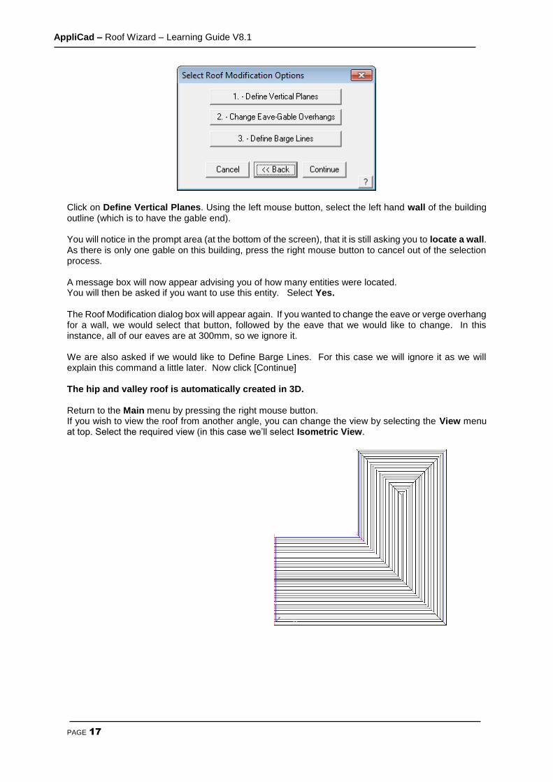
At this point, a dialog box will appear asking if you want to Define Vertical Planes, Change Eave-Verge Overhangs and Define Barge Line.
AppliCad – Roof Wizard – Learning Guide V8.1
PAGE 17
Click on Define Vertical Planes. Using the left mouse button, select the left hand wall of the building outline (which is to have the gable end). You will notice in the prompt area (at the bottom of the screen), that it is still asking you to locate a wall. As there is only one gable on this building, press the right mouse button to cancel out of the selection process. A message box will now appear advising you of how many entities were located. You will then be asked if you want to use this entity. Select Yes. The Roof Modification dialog box will appear again. If you wanted to change the eave or verge overhang for a wall, we would select that button, followed by the eave that we would like to change. In this instance, all of our eaves are at 300mm, so we ignore it. We are also asked if we would like to Define Barge Lines. For this case we will ignore it as we will explain this command a little later. Now click [Continue] The hip and valley roof is automatically created in 3D. Return to the Main menu by pressing the right mouse button. If you wish to view the roof from another angle, you can change the view by selecting the View menu at top. Select the required view (in this case we’ll select Isometric View.

AppliCad – Roof Wizard – Learning Guide V8.1
PAGE 18
Select Isometric View and then [OK]. This will enable us to look at the house in an isometric view. You may have to zoom fit the model by double clicking the centre mouse button to fit the entire model into the workspace. Note: If you change views and your roof seems to disappear, it is simply that you are zoomed into a small section of the drawing. You may need to zoom fit the appropriate view. This completes the exercise using Track-Outline.
Save Your Job To save your job select File > Save from the Main menu. The following dialog box will be displayed.
AppliCad – Roof Wizard – Learning Guide V8.1
PAGE 19
Type in your project or customer name in space under File Name and the job name in the space under Model Name , then select [OK]. For this exercise, use File Name TRAINING and Model Name Exercise 1. You’re Done!
Note: When you start work on real jobs, you will use your own job naming convention. You might for example use the name of the builder as the file name, and the site address as the model name. Eg: MightyBuilders for the file name, and 27LongStreet as the model name.
Do not use special keyboard characters in the file name – such as #,?,/,|,&, etc - in the names as it confuses software programs. To begin the next exercise, select File from the Pulldown menu at the top of the screen and select New. This will automatically clear the screen of the current job, or prompt you to save the current job if you haven’t already done so.
AppliCad – Roof Wizard – Learning Guide V8.1
PAGE 20
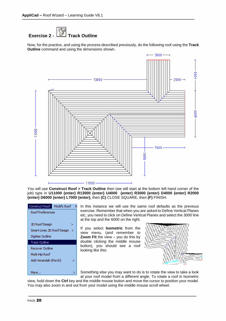
Exercise 2 - Track Outline Now, for the practice, and using the process described previously, do the following roof using the Track Outline command and using the dimensions shown.
You will use Construct Roof > Track Outline then (we will start at the bottom left hand corner of the job) type in U11000 {enter} R13000 {enter} U4000 {enter} R3000 {enter} D4000 {enter} R2000 {enter} D6000 {enter} L7000 {enter}, then (C) CLOSE SQUARE, then (F) FINISH.
In this instance we will use the same roof defaults as the previous exercise. Remember that when you are asked to Define Vertical Planes etc, you need to click on Define Vertical Planes and select the 3000 line at the top and the 6000 on the right. If you select Isometric from the view menu, (and remember to Zoom Fit the view – you do this by double clicking the middle mouse button), you should see a roof looking like this: Something else you may want to do is to rotate the view to take a look at your roof model from a different angle. To rotate a roof in Isometric
view, hold down the Ctrl key and the middle mouse button and move the cursor to position your model. You may also zoom in and out from your model using the middle mouse scroll wheel.

AppliCad – Roof Wizard – Learning Guide V8.1
PAGE 21
When you have finished, select File > Save As (from the top menu). You should see a file called Training.dab (which you created previously). Select this file on the left hand side and then type in Exercise 2 in the Model Name field. To begin the next exercise, select File from the pulldown menu at the top of the screen and select New. This will automatically clear the screen of the current job.
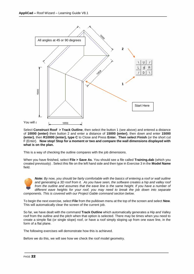
Exercise 3 - Track Outline – (using Angles) Now, using the commands already shown, try the roof outline below. An important thing to remember before you first begin to enter the values is to work out the best location of the Start Point based on what information you have been given. In this instance, there is one line which isn’t dimensioned (like that never happens on real drawings!) so we will use this line as our Closing Line, ie let the software calculate the length. We will be using the 45 degree direction button on the track outline dialogue this time. Another important thing to remember is that we cannot use Close Square on this job as the first and last lines are not at right angles to one another. We will use the Close Straight button this time. Leave the Roof Defaults as previously set. Try it for yourself and compare the result to the drawing below for the way it should have worked out.
Select a rotation point towards the front of the model (approx centre of floor plan)
Centre Point of Rotation is not at centre of
roof, but centre of floor plan.
AppliCad – Roof Wizard – Learning Guide V8.1
PAGE 22
You will achieve this by doing the following: Select Construct Roof > Track Outline, then select the button 1 (see above) and entered a distance of 10000 {enter} then button 2 and enter a distance of 15000 {enter}, then down and enter 15000 {enter}, then R10000 {enter}, type C to Close and Press Enter. Then select Finish (or the short cut F {Enter}. Now stop! Stop for a moment or two and compare the wall dimensions displayed with what is on the plan. This is a way of checking the outline compares with the job dimensions. When you have finished, select File > Save As. You should see a file called Training.dab (which you created previously) . Select this file on the left hand side and then type in Exercise 3 in the Model Name field.
Note: By now, you should be fairly comfortable with the basics of entering a roof or wall outline and generating a 3D roof from it. As you have seen, the software creates a hip and valley roof from the outline and assumes that the eave line is the same height. If you have a number of different eave heights for your roof, you may need to break the job down into separate
components. This is covered with our Project Gable command section below. To begin the next exercise, select File from the pulldown menu at the top of the screen and select New. This will automatically clear the screen of the current job. So far, we have dealt with the command Track Outline which automatically generates a Hip and Valley roof from the outline and the pitch when that option is selected. There may be times when you need to create a simple flat (or single slope) roof, or have a roof simply sloping up from one eave line, in the form of a flat plane. The following exercises will demonstrate how this is achieved. Before we do this, we will see how we check the roof model geometry.
All angles at 45 or 90 degrees
Start Here
2
1
AppliCad – Roof Wizard – Learning Guide V8.1
PAGE 23
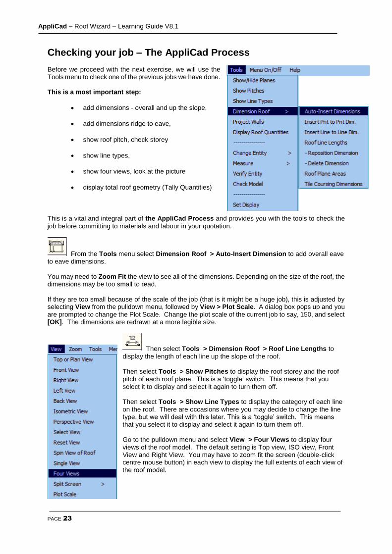
Checking your job – The AppliCad Process Before we proceed with the next exercise, we will use the Tools menu to check one of the previous jobs we have done. This is a most important step:
add dimensions - overall and up the slope,
add dimensions ridge to eave,
show roof pitch, check storey
show line types,
show four views, look at the picture
display total roof geometry (Tally Quantities)
This is a vital and integral part of the AppliCad Process and provides you with the tools to check the job before committing to materials and labour in your quotation.
From the Tools menu select Dimension Roof > Auto-Insert Dimension to add overall eave to eave dimensions. You may need to Zoom Fit the view to see all of the dimensions. Depending on the size of the roof, the dimensions may be too small to read. If they are too small because of the scale of the job (that is it might be a huge job), this is adjusted by selecting View from the pulldown menu, followed by View > Plot Scale. A dialog box pops up and you are prompted to change the Plot Scale. Change the plot scale of the current job to say, 150, and select [OK]. The dimensions are redrawn at a more legible size.
Then select Tools > Dimension Roof > Roof Line Lengths to display the length of each line up the slope of the roof. Then select Tools > Show Pitches to display the roof storey and the roof pitch of each roof plane. This is a ‘toggle’ switch. This means that you select it to display and select it again to turn them off. Then select Tools > Show Line Types to display the category of each line on the roof. There are occasions where you may decide to change the line type, but we will deal with this later. This is a ‘toggle’ switch. This means that you select it to display and select it again to turn them off. Go to the pulldown menu and select View > Four Views to display four views of the roof model. The default setting is Top view, ISO view, Front View and Right View. You may have to zoom fit the screen (double-click centre mouse button) in each view to display the full extents of each view of the roof model.

AppliCad – Roof Wizard – Learning Guide V8.1
PAGE 24
Finally, to get geometric quantities, select Tools > Tally-Quantities. Select this and a dialog box is displayed with a summary of the geometric areas and lengths of the current roof.
This function may also be accessed from the Icon Menu – >
Important Note: The steps described above are imperative. Use them on every job without fail so that you check every aspect of the roof geometry BEFORE you determine material quantities. Better to find a problem now, than when you have delivered the job!
AppliCad – Roof Wizard – Learning Guide V8.1
PAGE 25
Notice also that you can export this information to a .csv (Comma Separated Values) format ascii text file using the Export CSV as well as an XLS file format button, so that this basic roof geometry information may be used in other systems that may be using in your business with Microsoft Excel.
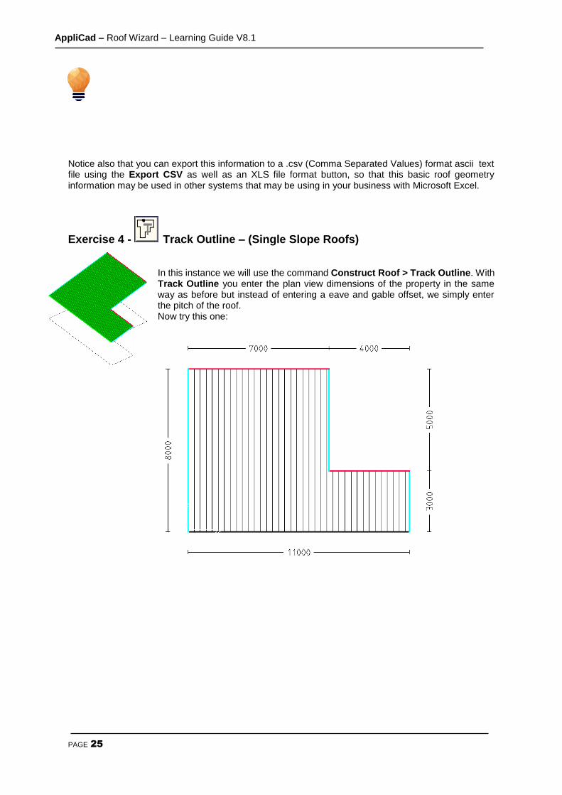
Exercise 4 - Track Outline – (Single Slope Roofs) In this instance we will use the command Construct Roof > Track Outline. With Track Outline you enter the plan view dimensions of the property in the same way as before but instead of entering a eave and gable offset, we simply enter the pitch of the roof. Now try this one:
AppliCad – Roof Wizard – Learning Guide V8.1
PAGE 26
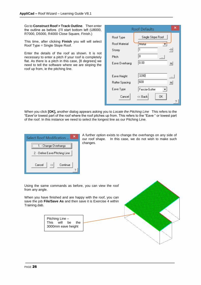
Go to Construct Roof > Track Outline. Then enter the outline as before. (I’ll start bottom left (U8000, R7000, D5000, R4000 Close Square, Finish.) This time, after clicking Finish you will will select Roof Type = Single Slope Roof. Enter the details of the roof as shown. It is not necessary to enter a pitch if your roof is completely flat. As there is a pitch in this case, [8 degrees] we need to tell the software where we are sloping the roof up from, ie the pitching line. When you click [OK], another dialog appears asking you to Locate the Pitching Line This refers to the “Eave“or lowest part of the roof where the roof pitches up from. This refers to the “Eave “ or lowest part of the roof. In this instance we need to select the longest line as our Pitching Line.
A further option exists to change the overhangs on any side of our roof shape. In this case, we do not wish to make such changes.
Using the same commands as before, you can view the roof from any angle. When you have finished and are happy with the roof, you can save the job File/Save As and then save it is Exercise 4 within Training.dab.
Pitching Line – This will be the 3000mm eave height
AppliCad – Roof Wizard – Learning Guide V8.1
PAGE 27
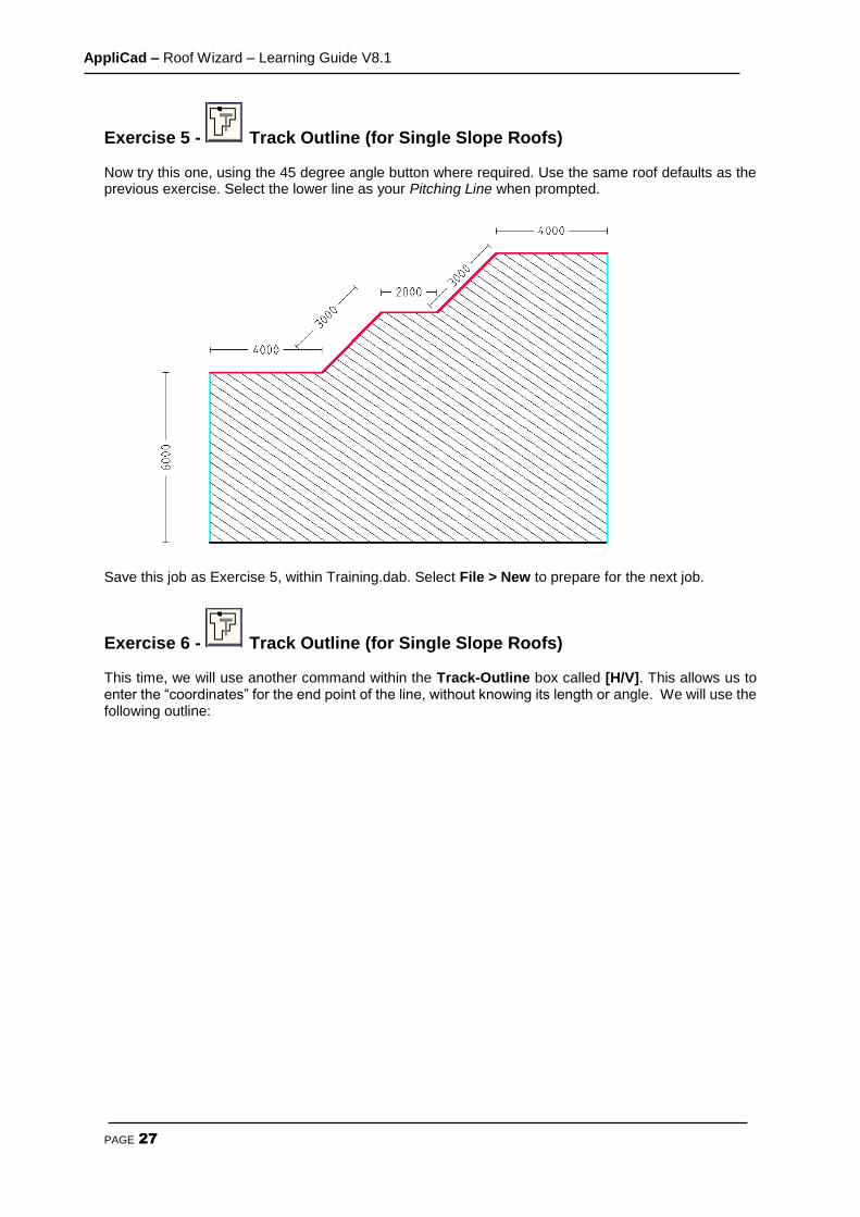
Exercise 5 - Track Outline (for Single Slope Roofs) Now try this one, using the 45 degree angle button where required. Use the same roof defaults as the previous exercise. Select the lower line as your Pitching Line when prompted.
Save this job as Exercise 5, within Training.dab. Select File > New to prepare for the next job.
Exercise 6 - Track Outline (for Single Slope Roofs) This time, we will use another command within the Track-Outline box called [H/V]. This allows us to enter the “coordinates” for the end point of the line, without knowing its length or angle. We will use the following outline:

AppliCad – Roof Wizard – Learning Guide V8.1
PAGE 28
To achieve this outline, select Construct Roof > Track Outline. Then insert the first line as U5000 {enter}. The next line is going at an angle and we don’t know the angle or the length but we know the location of the end point. Select [H/V] and you will see the following box appear; Enter the values as shown and click [OK] and you will see the line on the screen. The next line is horizontal so we can simply enter R2000 {enter}. The next line is at an angle so click on Hor-Vert and enter the Horizontal and vertical values again. It is important to get the correct values, either Positive or Negative, depending on the direction of the line. Enter a value of 3000 for the Horizontal Distance and (negative) – 2000 and click [OK]. Next we need to use [H/V] and enter a Negative value for both horizontal and vertical distances. You can end the outline the by Closing Straight and then Finish. Set a pitch of 0 this time. When you have finished, have a practice with changing views and when ready, save the job as Exercise 6 in Training.dab. It is very important to get your head around the concept of 3D space and positive and negative numbers. Any distances going to the Right or Up are Positive, distances to the Left or Down are Negative. The purpose of adding the dimensions is to further confirm that the outline has been correctly defined.
Note: the dimensions in this exercise refer to the actual roof outline – not the wall outline, so they will take into account any eave and gable overhang. If you were digitising the wall and you had overhang, then don’t forget to add it in the field provided.
Start here and work clockwise
AppliCad – Roof Wizard – Learning Guide V8.1
PAGE 29
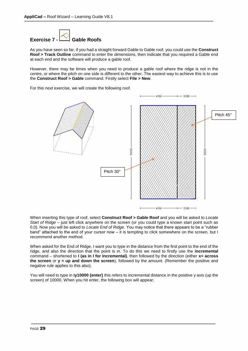
Exercise 7 - Gable Roofs As you have seen so far, if you had a straight forward Gable to Gable roof, you could use the Construct Roof > Track Outline command to enter the dimensions, then indicate that you required a Gable end at each end and the software will produce a gable roof. However, there may be times when you need to produce a gable roof where the ridge is not in the centre, or where the pitch on one side is different to the other. The easiest way to achieve this is to use the Construct Roof > Gable command. Firstly select File > New. For this next exercise, we will create the following roof. When inserting this type of roof, select Construct Roof > Gable Roof and you will be asked to Locate Start of Ridge – just left click anywhere on the screen (or you could type a known start point such as 0,0). Now you will be asked to Locate End of Ridge. You may notice that there appears to be a “rubber band” attached to the end of your cursor now – it is tempting to click somewhere on the screen, but I recommend another method. When asked for the End of Ridge, I want you to type in the distance from the first point to the end of the ridge, and also the direction that the point is in. To do this we need to firstly use the incremental command – shortened to I (as in I for Incremental), then followed by the direction (either x= across the screen or y = up and down the screen), followed by the amount. (Remember the positive and negative rule applies to this also). You will need to type in iy10000 {enter} this refers to incremental distance in the positive y axis (up the screen) of 10000. When you hit enter, the following box will appear;
Pitch 30°
Pitch 45°
AppliCad – Roof Wizard – Learning Guide V8.1
PAGE 30
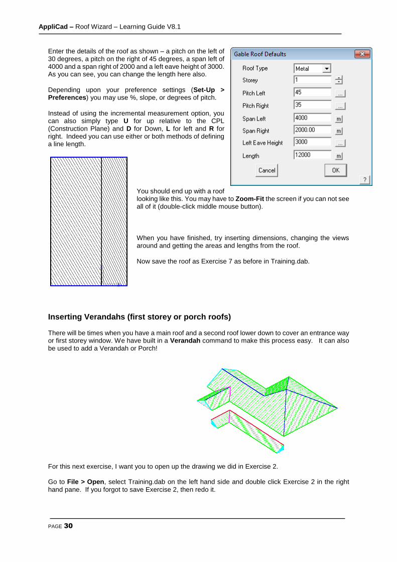
Enter the details of the roof as shown – a pitch on the left of 30 degrees, a pitch on the right of 45 degrees, a span left of 4000 and a span right of 2000 and a left eave height of 3000. As you can see, you can change the length here also.
Depending upon your preference settings (Set-Up > Preferences) you may use %, slope, or degrees of pitch.
Instead of using the incremental measurement option, you can also simply type U for up relative to the CPL (Construction Plane) and D for Down, L for left and R for right. Indeed you can use either or both methods of defining a line length.
You should end up with a roof looking like this. You may have to Zoom-Fit the screen if you can not see all of it (double-click middle mouse button).
When you have finished, try inserting dimensions, changing the views around and getting the areas and lengths from the roof.
Now save the roof as Exercise 7 as before in Training.dab.
Inserting Verandahs (first storey or porch roofs) There will be times when you have a main roof and a second roof lower down to cover an entrance way or first storey window. We have built in a Verandah command to make this process easy. It can also be used to add a Verandah or Porch!
For this next exercise, I want you to open up the drawing we did in Exercise 2. Go to File > Open, select Training.dab on the left hand side and double click Exercise 2 in the right hand pane. If you forgot to save Exercise 2, then redo it.
AppliCad – Roof Wizard – Learning Guide V8.1
PAGE 31
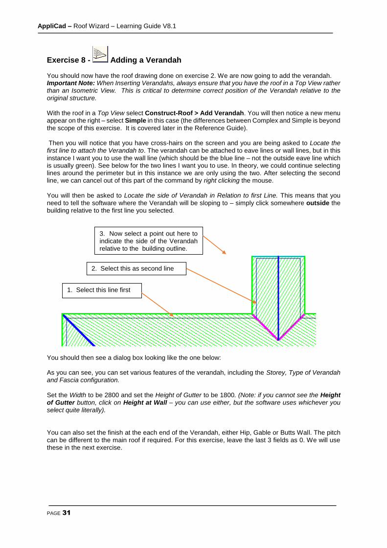
Exercise 8 - Adding a Verandah You should now have the roof drawing done on exercise 2. We are now going to add the verandah. Important Note: When Inserting Verandahs, always ensure that you have the roof in a Top View rather than an Isometric View. This is critical to determine correct position of the Verandah relative to the original structure. With the roof in a Top View select Construct-Roof > Add Verandah. You will then notice a new menu appear on the right – select Simple in this case (the differences between Complex and Simple is beyond the scope of this exercise. It is covered later in the Reference Guide). Then you will notice that you have cross-hairs on the screen and you are being asked to Locate the first line to attach the Verandah to. The verandah can be attached to eave lines or wall lines, but in this instance I want you to use the wall line (which should be the blue line – not the outside eave line which is usually green). See below for the two lines I want you to use. In theory, we could continue selecting lines around the perimeter but in this instance we are only using the two. After selecting the second line, we can cancel out of this part of the command by right clicking the mouse. You will then be asked to Locate the side of Verandah in Relation to first Line. This means that you need to tell the software where the Verandah will be sloping to – simply click somewhere outside the building relative to the first line you selected.
You should then see a dialog box looking like the one below: As you can see, you can set various features of the verandah, including the Storey, Type of Verandah and Fascia configuration. Set the Width to be 2800 and set the Height of Gutter to be 1800. (Note: if you cannot see the Height of Gutter button, click on Height at Wall – you can use either, but the software uses whichever you select quite literally). You can also set the finish at the each end of the Verandah, either Hip, Gable or Butts Wall. The pitch can be different to the main roof if required. For this exercise, leave the last 3 fields as 0. We will use these in the next exercise.
1. Select this line first
2. Select this as second line
3. Now select a point out here to indicate the side of the Verandah relative to the building outline.

AppliCad – Roof Wizard – Learning Guide V8.1
PAGE 32
If you wish to see what the verandah may look like, click Preview and you should see your verandah (displayed with white lines) on the screen. Things to check in the preview are the start and end preparation, as selecting the correct treatment ensures that the right material will be applied when you get to that stage. If they are not correct, change the setting and select preview again.
Note: If the dialog box obscures the view of the roof, move your cursor to the blue strip at the top of the box and, whilst holding down the left mouse button, drag the dialog box to a more suitable location on the screen.
If the Verandah looks correct, click [OK] and you should see this.
As you know, you can change the view to make sure that it has gone in at the correct height. If you make a mistake with any Roof Modeling functions such as inserting the Verandah, you can use the Undo and Redo commands on the Icon Menu to step back to the previous command. Try it for yourself. Now that we have made some changes, we might want to save it as a new name. Select File > Save as and then save it as Exercise 8 within Training.dab

AppliCad – Roof Wizard – Learning Guide V8.1
PAGE 33
Exercise 9 - Adding a Verandah II For this exercise, we will open up the roof we created in Exercise 1. The end result will look like this:
In the previous exercise, you will have noticed that the verandah was built along the full length of each wall that we selected. There will be many instances where the verandah is only part of the way along a wall. For this function we need specify the Distance from First Point and Distance from Last Point (It is indicated on the screen which are the first and last points) After making sure that your roof is in a top view, select Construct-Roof > Add Verandah and select the two wall lines (blue lines) where the verandah is attached. Then right click the mouse and when asked for the side of the verandah, left click somewhere outside the building, in relation to the first line you selected.
This time, when entering the information about the verandah, change the Start Preparation to Hip and set the Distance from first point to 2000 and Last Point to 10000. Preview the roof and then click [OK] when happy. Change the views to check the height is correct.
Note: A common mistake when inserting Verandahs is to insert at the wrong height. If your verandah looks wrong, UNDO and repeat the process, ensuring that you have set the correct Height of Gutter or Height at Wall button on the dialog box.
Undo Redo
Save this job as Exercise 9 in Training.dab.
AppliCad – Roof Wizard – Learning Guide V8.1
PAGE 34
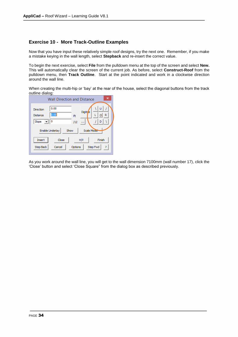
Exercise 10 - More Track-Outline Examples Now that you have input these relatively simple roof designs, try the next one. Remember, if you make a mistake keying in the wall length, select Stepback and re-insert the correct value. To begin the next exercise, select File from the pulldown menu at the top of the screen and select New. This will automatically clear the screen of the current job. As before, select Construct-Roof from the pulldown menu, then Track Outline. Start at the point indicated and work in a clockwise direction around the wall line. When creating the multi-hip or ‘bay’ at the rear of the house, select the diagonal buttons from the track outline dialog:
As you work around the wall line, you will get to the wall dimension 7100mm (wall number 17), click the ‘Close’ button and select ‘Close Square” from the dialog box as described previously.

AppliCad – Roof Wizard – Learning Guide V8.1
PAGE 35
This will automatically complete the wall definition for you. Complete the Roof Defaults box , giving a pitch of 35 and an eave height of 4000mm and an eave overhang of 300mm then select [OK] to finish. When you’ve finished, save this job as Exercise 10 in Training.dab.
AppliCad – Roof Wizard – Learning Guide V8.1
PAGE 36
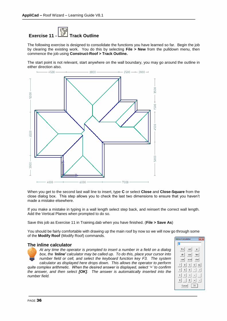
Exercise 11 - Track Outline The following exercise is designed to consolidate the functions you have learned so far. Begin the job by clearing the existing work. You do this by selecting File > New from the pulldown menu, then commence the job using Construct-Roof > Track Outline. The start point is not relevant, start anywhere on the wall boundary, you may go around the outline in either direction also.
When you get to the second last wall line to insert, type C or select Close and Close-Square from the close dialog box. This step allows you to check the last two dimensions to ensure that you haven’t made a mistake elsewhere. If you make a mistake in typing in a wall length select step back, and reinsert the correct wall length. Add the Vertical Planes when prompted to do so. Save this job as Exercise 11 in Training.dab when you have finished. (File > Save As) You should be fairly comfortable with drawing up the main roof by now so we will now go through some of the Modify Roof (Modify Roof) commands.
The inline calculator At any time the operator is prompted to insert a number in a field on a dialog box, the ‘Inline’ calculator may be called up. To do this, place your cursor into number field or cell, and select the keyboard function key F3. The system calculator as displayed here drops down. This allows the operator to perform
quite complex arithmetic. When the desired answer is displayed, select ‘=’ to confirm the answer, and then select [OK]. The answer is automatically inserted into the number field.
AppliCad – Roof Wizard – Learning Guide V8.1
PAGE 37
The Modify Roof Command
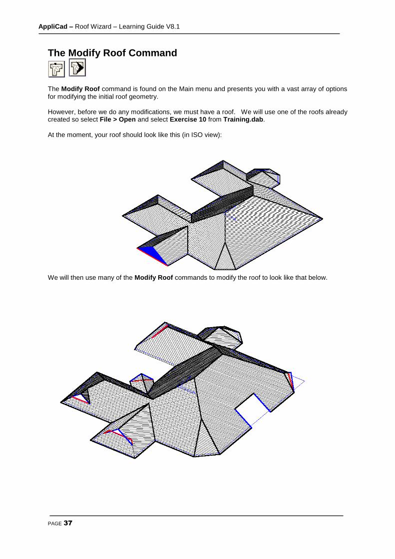
The Modify Roof command is found on the Main menu and presents you with a vast array of options for modifying the initial roof geometry. However, before we do any modifications, we must have a roof. We will use one of the roofs already created so select File > Open and select Exercise 10 from Training.dab. At the moment, your roof should look like this (in ISO view):
We will then use many of the Modify Roof commands to modify the roof to look like that below.

AppliCad – Roof Wizard – Learning Guide V8.1
PAGE 38
Exercise 12 - Modify Roof > Atrium First of all we will add an Atrium to our new roof. This could also be used to create the space required for a chimney or an adjoining structure. Select Atrium from the Modify Roof menu. You will be prompted to Locate eave line. Using the left mouse button, locate the eave line towards the bottom of the right hand eave line. This way the Distance along eave that you type in, will be measured from the bottom of the line and not the top. The start point from which it is calculating the distance is flashing, to highlight the fact to the operator.
Set up the values in the defaults dialog box in accordance with the picture below. Select [OK] with the left mouse button and the Atrium is automatically drawn in.
Hint: A negative depth value would create a drag-down effect on the eave line ie project past the eave line at the same pitch of the roof, rather than cut into the roof. You may select UNDO from the icon menu to remove the atrium you just added, and try adding a dropped eave using
the Atrium command.
Exercise 13 - Modify Roof > Valley-Gable
The Valley-Gable command allows you to create Vertical Planes on either internal or external corners (ie valleys or hips). In some situations, and as we have shown here, it is best to firstly ignore this roof feature when defining the wall outline, knowing we have the tools to insert it accurately and far more easily later. The command may also be used to add a flat plane roof section.
(refer to Section 5 for more details).
First select Valley-Gable from the Modify Roof menu. You
will then be prompted to Locate valley or hip line to add a gable.
Locate the hip line in the top right hand corner of the example plan.
Set the values to those in the dialog box below:
AppliCad – Roof Wizard – Learning Guide V8.1
PAGE 39
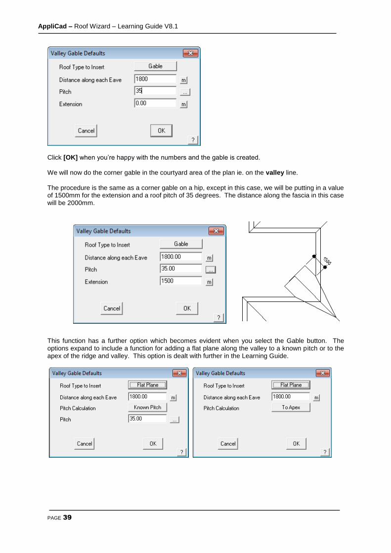
Click [OK] when you’re happy with the numbers and the gable is created. We will now do the corner gable in the courtyard area of the plan ie. on the valley line. The procedure is the same as a corner gable on a hip, except in this case, we will be putting in a value of 1500mm for the extension and a roof pitch of 35 degrees. The distance along the fascia in this case will be 2000mm.
This function has a further option which becomes evident when you select the Gable button. The options expand to include a function for adding a flat plane along the valley to a known pitch or to the apex of the ridge and valley. This option is dealt with further in the Learning Guide.
AppliCad – Roof Wizard – Learning Guide V8.1
PAGE 40
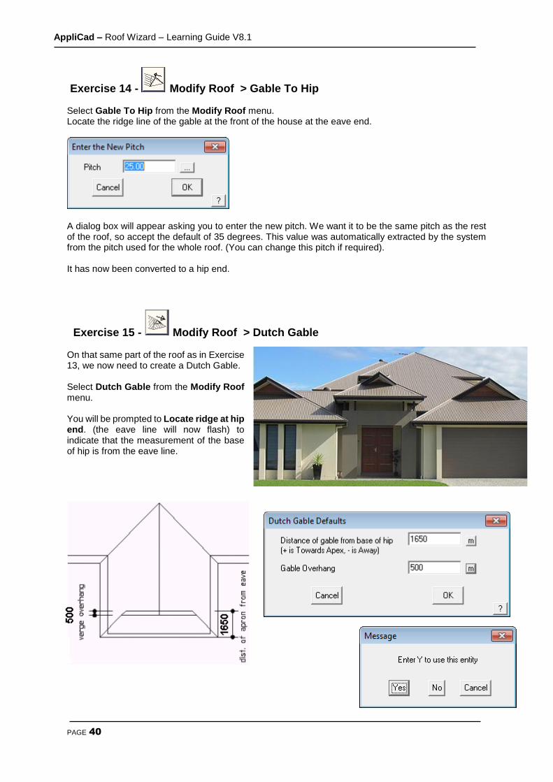
Exercise 14 - Modify Roof > Gable To Hip Select Gable To Hip from the Modify Roof menu. Locate the ridge line of the gable at the front of the house at the eave end.
A dialog box will appear asking you to enter the new pitch. We want it to be the same pitch as the rest of the roof, so accept the default of 35 degrees. This value was automatically extracted by the system from the pitch used for the whole roof. (You can change this pitch if required). It has now been converted to a hip end.
Exercise 15 - Modify Roof > Dutch Gable On that same part of the roof as in Exercise 13, we now need to create a Dutch Gable. Select Dutch Gable from the Modify Roof menu. You will be prompted to Locate ridge at hip end. (the eave line will now flash) to indicate that the measurement of the base of hip is from the eave line.
AppliCad – Roof Wizard – Learning Guide V8.1
PAGE 41
Useful Tip: When you select a line or point and you may see a dialog box appear asking you to ‘Enter Y to use this entity’. It means that the software has found a number of points in the vicinity, and is asking you to
confirm if the feature flashing on the screen is the correct one. You can select the options on this dialog box by using the mouse button short cuts: yes – no – cancel can be selected by left – middle – right on a three button mouse without selecting the buttons on the dialog. Try this, it saves time when you get accustomed to it!
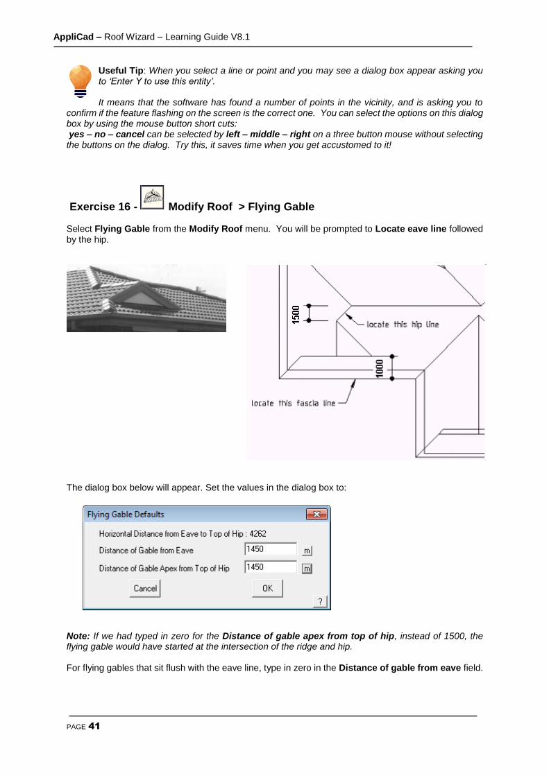
Exercise 16 - Modify Roof > Flying Gable Select Flying Gable from the Modify Roof menu. You will be prompted to Locate eave line followed by the hip.
The dialog box below will appear. Set the values in the dialog box to:
Note: If we had typed in zero for the Distance of gable apex from top of hip, instead of 1500, the flying gable would have started at the intersection of the ridge and hip. For flying gables that sit flush with the eave line, type in zero in the Distance of gable from eave field.
AppliCad – Roof Wizard – Learning Guide V8.1
PAGE 42
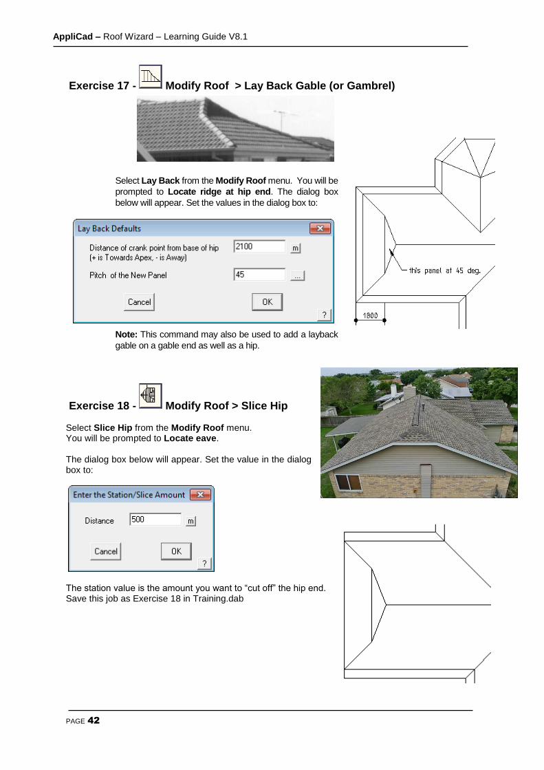
Exercise 17 - Modify Roof > Lay Back Gable (or Gambrel)
Select Lay Back from the Modify Roof menu. You will be
prompted to Locate ridge at hip end. The dialog box
below will appear. Set the values in the dialog box to:
Note: This command may also be used to add a layback
gable on a gable end as well as a hip.
Exercise 18 - Modify Roof > Slice Hip Select Slice Hip from the Modify Roof menu. You will be prompted to Locate eave. The dialog box below will appear. Set the value in the dialog box to:
The station value is the amount you want to “cut off” the hip end. Save this job as Exercise 18 in Training.dab
AppliCad – Roof Wizard – Learning Guide V8.1
PAGE 43
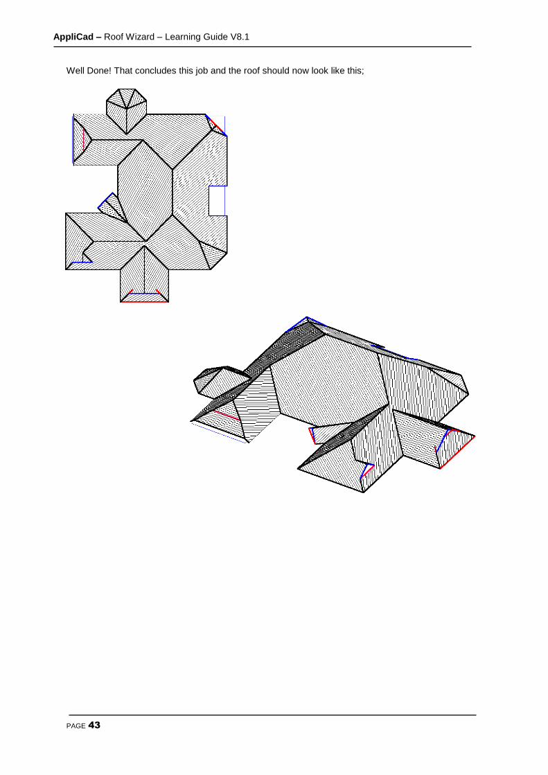
Well Done! That concludes this job and the roof should now look like this;
AppliCad – Roof Wizard – Learning Guide V8.1
PAGE 44
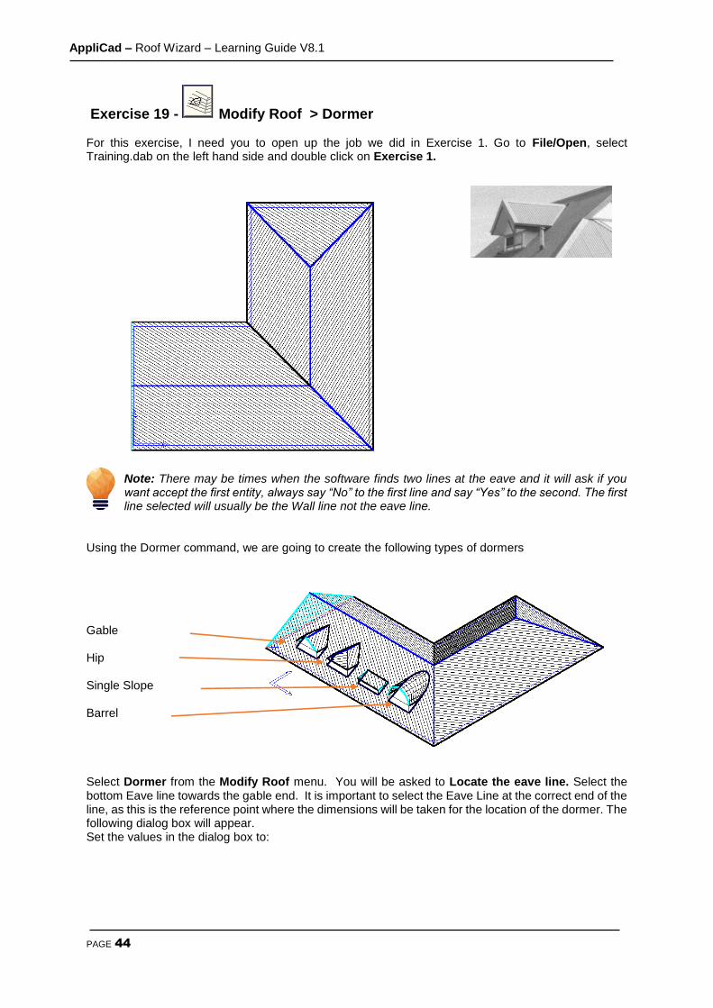
Exercise 19 - Modify Roof > Dormer For this exercise, I need you to open up the job we did in Exercise 1. Go to File/Open, select Training.dab on the left hand side and double click on Exercise 1.
Note: There may be times when the software finds two lines at the eave and it will ask if you want accept the first entity, always say “No” to the first line and say “Yes” to the second. The first line selected will usually be the Wall line not the eave line.
Using the Dormer command, we are going to create the following types of dormers Gable Hip Single Slope Barrel Select Dormer from the Modify Roof menu. You will be asked to Locate the eave line. Select the bottom Eave line towards the gable end. It is important to select the Eave Line at the correct end of the line, as this is the reference point where the dimensions will be taken for the location of the dormer. The following dialog box will appear. Set the values in the dialog box to:
AppliCad – Roof Wizard – Learning Guide V8.1
PAGE 45
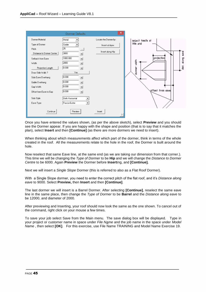
Once you have entered the values shown, (as per the above sketch), select Preview and you should see the Dormer appear. If you are happy with the shape and position (that is to say that it matches the plan), select Insert and then [Continue] (as there are more dormers we need to insert). When thinking about which measurements affect which part of the dormer, think in terms of the whole created in the roof. All the measurements relate to the hole in the roof, the Dormer is built around the hole. Now reselect that same Eave line, at the same end (as we are taking our dimension from that corner.). This time we will be changing the Type of Dormer to be Hip and we will change the Distance to Dormer Centre to be 6000. Again Preview the Dormer before Inserting, and [Continue]. Next we will insert a Single Slope Dormer (this is referred to also as a Flat Roof Dormer). With a Single Slope dormer, you need to enter the correct pitch of the flat roof, and it’s Distance along eave to 9000. Select Preview, then Insert and then [Continue]. The last dormer we will insert is a Barrel Dormer. After selecting [Continue], reselect the same eave line in the same place, then change the Type of Dormer to be Barrel and the Distance along eave to be 12000, and diameter of 2000. After previewing and Inserting, your roof should now look the same as the one shown. To cancel out of the command, right click on your mouse a few times. To save your job select Save from the Main menu. The save dialog box will be displayed. Type in your project or customer name in space under File Name and the job name in the space under Model Name , then select [OK]. For this exercise, use File Name TRAINING and Model Name Exercise 19.

AppliCad – Roof Wizard – Learning Guide V8.1
PAGE 46
Exercise 20 - Modify Roof > Split Gable
Before we explore the Split Gable command, we need to have a simple gable roof on screen first. Select File > New and then select Construct-Roof > Track Outline and enter the following wall dimensions;
Using the values shown on the left, create your roof and remember to select the left and right wall lines when asked if you want any Gable Ends. After you have created the gable roof, select the Modify Roof menu, then Split-Gable. You will be prompted to Locate ridge at gable end. Locate the ridge at the end closest to the left of the screen. The end of ridge you select determines which end the Split-Gable is inserted on the roof.

AppliCad – Roof Wizard – Learning Guide V8.1
PAGE 47
The dialog box will appear. Set the values to those shown below: You should end up with the drawing below.
So that you can go back to this exercise, you should save it. To save your job select Save from the Main menu. The save dialog box will be displayed. Type in your project or customer name in space under File Name and the job name in the space under Model Name, then select [OK]. For this exercise, use File Name TRAINING and Model Name Exercise 20
Exercise 21 - Modify Roof > Project Gable Using the roof from the previous exercise, we will draw a line indicating a boundary line. To draw the boundary line, select Modify Roof from the Main menu, then select Advanced, Ins-Line, then Free. With the left mouse button, digitise two points on screen where you want the boundary line to appear. For the purposes of this exercise, digitise your boundary line anywhere approximately as shown below. Then double click the right mouse button to cancel the line insert function as you have finished inserting the line.
AppliCad – Roof Wizard – Learning Guide V8.1
PAGE 48
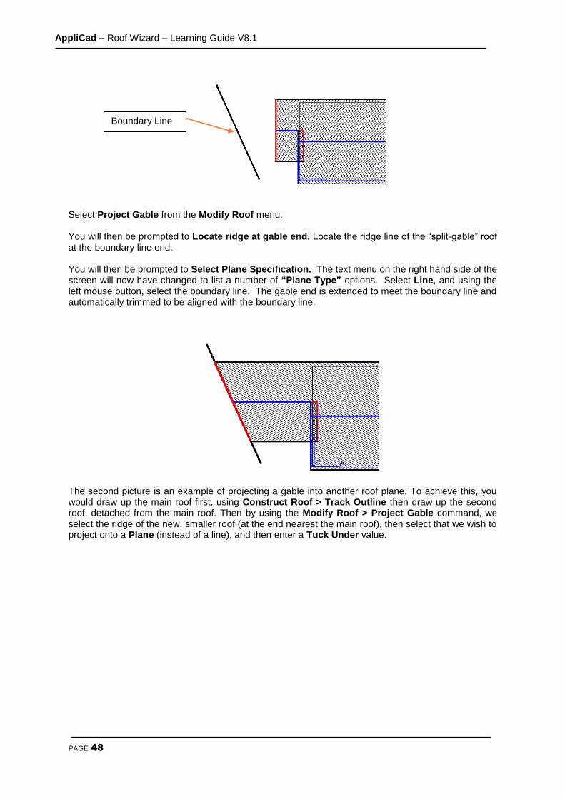
Select Project Gable from the Modify Roof menu. You will then be prompted to Locate ridge at gable end. Locate the ridge line of the “split-gable” roof at the boundary line end. You will then be prompted to Select Plane Specification. The text menu on the right hand side of the screen will now have changed to list a number of “Plane Type” options. Select Line, and using the left mouse button, select the boundary line. The gable end is extended to meet the boundary line and automatically trimmed to be aligned with the boundary line.
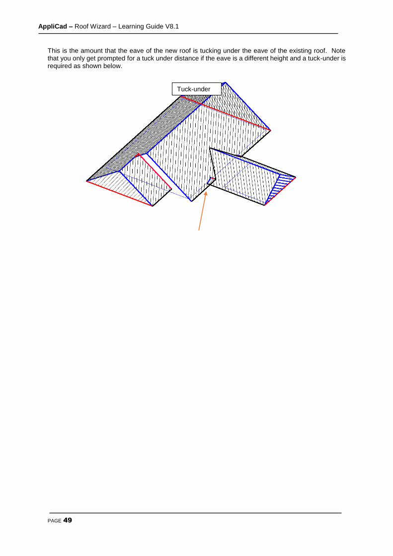
The second picture is an example of projecting a gable into another roof plane. To achieve this, you would draw up the main roof first, using Construct Roof > Track Outline then draw up the second roof, detached from the main roof. Then by using the Modify Roof > Project Gable command, we select the ridge of the new, smaller roof (at the end nearest the main roof), then select that we wish to project onto a Plane (instead of a line), and then enter a Tuck Under value.
Boundary Line
AppliCad – Roof Wizard – Learning Guide V8.1
PAGE 49
This is the amount that the eave of the new roof is tucking under the eave of the existing roof. Note that you only get prompted for a tuck under distance if the eave is a different height and a tuck-under is required as shown below.
Tuck-under
AppliCad – Roof Wizard – Learning Guide V8.1
PAGE 50
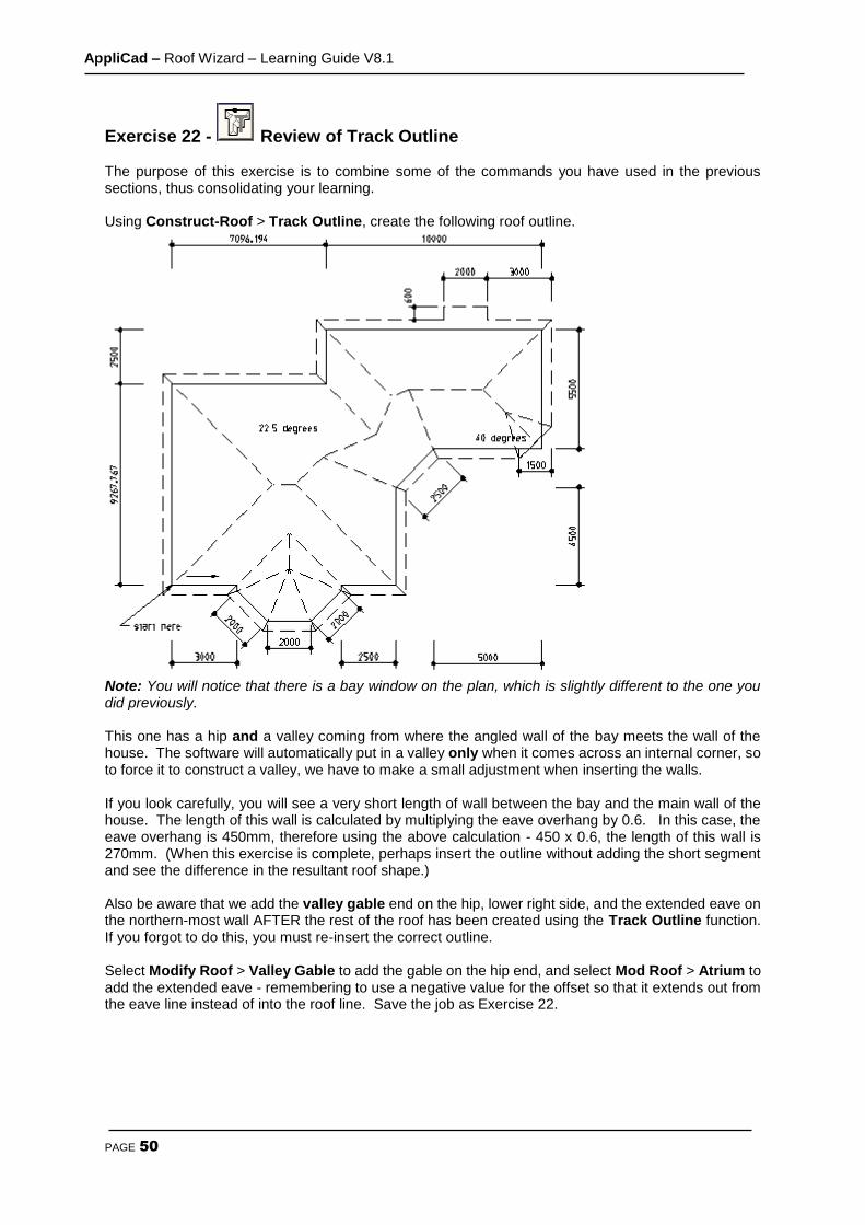
Exercise 22 - Review of Track Outline The purpose of this exercise is to combine some of the commands you have used in the previous sections, thus consolidating your learning. Using Construct-Roof > Track Outline, create the following roof outline.
Note: You will notice that there is a bay window on the plan, which is slightly different to the one you did previously. This one has a hip and a valley coming from where the angled wall of the bay meets the wall of the house. The software will automatically put in a valley only when it comes across an internal corner, so to force it to construct a valley, we have to make a small adjustment when inserting the walls. If you look carefully, you will see a very short length of wall between the bay and the main wall of the house. The length of this wall is calculated by multiplying the eave overhang by 0.6. In this case, the eave overhang is 450mm, therefore using the above calculation - 450 x 0.6, the length of this wall is 270mm. (When this exercise is complete, perhaps insert the outline without adding the short segment and see the difference in the resultant roof shape.) Also be aware that we add the valley gable end on the hip, lower right side, and the extended eave on the northern-most wall AFTER the rest of the roof has been created using the Track Outline function. If you forgot to do this, you must re-insert the correct outline. Select Modify Roof > Valley Gable to add the gable on the hip end, and select Mod Roof > Atrium to add the extended eave - remembering to use a negative value for the offset so that it extends out from the eave line instead of into the roof line. Save the job as Exercise 22.
AppliCad – Roof Wizard – Learning Guide V8.1
PAGE 51
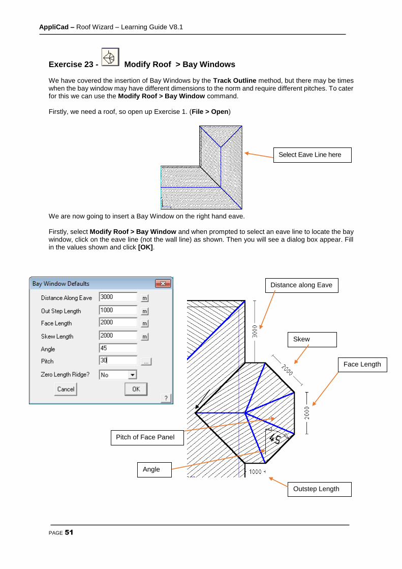
Exercise 23 - Modify Roof > Bay Windows We have covered the insertion of Bay Windows by the Track Outline method, but there may be times when the bay window may have different dimensions to the norm and require different pitches. To cater for this we can use the Modify Roof > Bay Window command. Firstly, we need a roof, so open up Exercise 1. (File > Open)
We are now going to insert a Bay Window on the right hand eave. Firstly, select Modify Roof > Bay Window and when prompted to select an eave line to locate the bay window, click on the eave line (not the wall line) as shown. Then you will see a dialog box appear. Fill in the values shown and click [OK].
Select Eave Line here
Distance along Eave
Outstep Length
Skew Length
Angle
Pitch of Face Panel
Face Length

AppliCad – Roof Wizard – Learning Guide V8.1
PAGE 52
Exercise 24 - Modify Roof > More… > Cut-Out The next exercise will involve the creation of a typical 2 storey house. We will be using a command called Cutout, which will be used to remove the area of roof from underneath the second storey.
Firstly, draw the single storey first, to the dimensions below, with a pitch of 22.5 and an eave overhang of 450mm. Select Construct-Roof then Track Outline.
In order for us to position the second storey correctly, relative to the first storey, we need to specify a reference (or datum) start point for the wall outline of the second storey. From this reference point, we then indicate the distance from the reference point to the start point of our second storey. The important thing to remember is that we need to be very precise in locating our Reference Point, so we will use the middle button on your mouse to “Snap” to the correct point indicated on the drawing overleaf. (If you haven’t already setup your middle mouse button, please refer to the Set-Up Guide).

AppliCad – Roof Wizard – Learning Guide V8.1
PAGE 53
After the first storey is completed, select Construct-Roof ,and after the Track Outline dialogue pops up, select datum button in the middle of the accelerator buttons
Then you will be prompted to for a reference point from which to set the new start point. Middle button ‘snap’. Snapping to a point uses the existing point to start the outline instead of creating a new point. If you are not using a 3 button mouse, you can also ‘snap’ the point by holding the Shift key whilst pressing the left button over the point indicated. Once you have “snapped” to that point, you will see the following box appear. You should be familiar with the workings of this box, but this time we are simply entering the offset distances to reach the Start Point of the Second Storey outline relative to the reference point. In this instance, we will need to enter the Hor-Vert distances shown in the dialog above
Once you click [OK] and you will then see the normal Track Outline box appear (a clue here – it will be headed at the top with Wall Direction and Distance). Now you can enter R10900 {enter} U6200 {enter} C or Close Sq., then F or Finish. When the Roof Defaults dialog box appears, be sure to set the Storey to 2, and the Eave height to 6000mm.
AppliCad – Roof Wizard – Learning Guide V8.1
PAGE 54
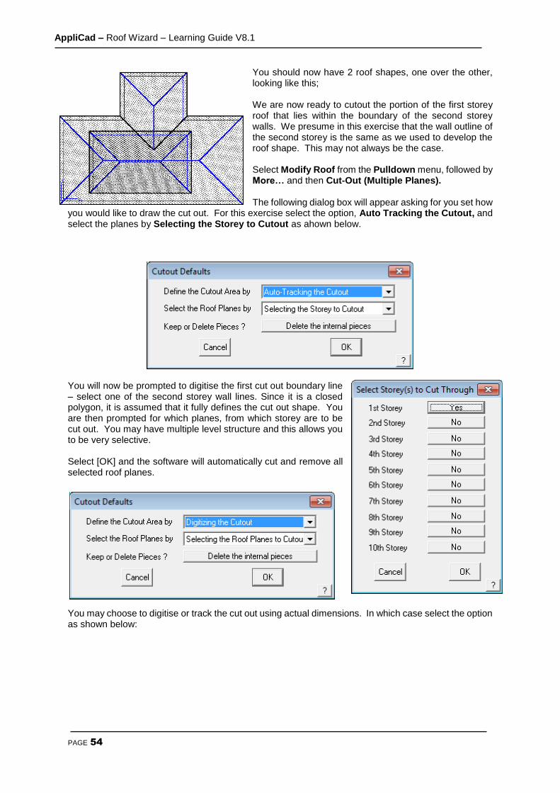
You should now have 2 roof shapes, one over the other, looking like this; We are now ready to cutout the portion of the first storey roof that lies within the boundary of the second storey walls. We presume in this exercise that the wall outline of the second storey is the same as we used to develop the roof shape. This may not always be the case. Select Modify Roof from the Pulldown menu, followed by More… and then Cut-Out (Multiple Planes). The following dialog box will appear asking for you set how
you would like to draw the cut out. For this exercise select the option, Auto Tracking the Cutout, and select the planes by Selecting the Storey to Cutout as ahown below.
You will now be prompted to digitise the first cut out boundary line – select one of the second storey wall lines. Since it is a closed polygon, it is assumed that it fully defines the cut out shape. You are then prompted for which planes, from which storey are to be cut out. You may have multiple level structure and this allows you to be very selective. Select [OK] and the software will automatically cut and remove all selected roof planes.
You may choose to digitise or track the cut out using actual dimensions. In which case select the option as shown below:
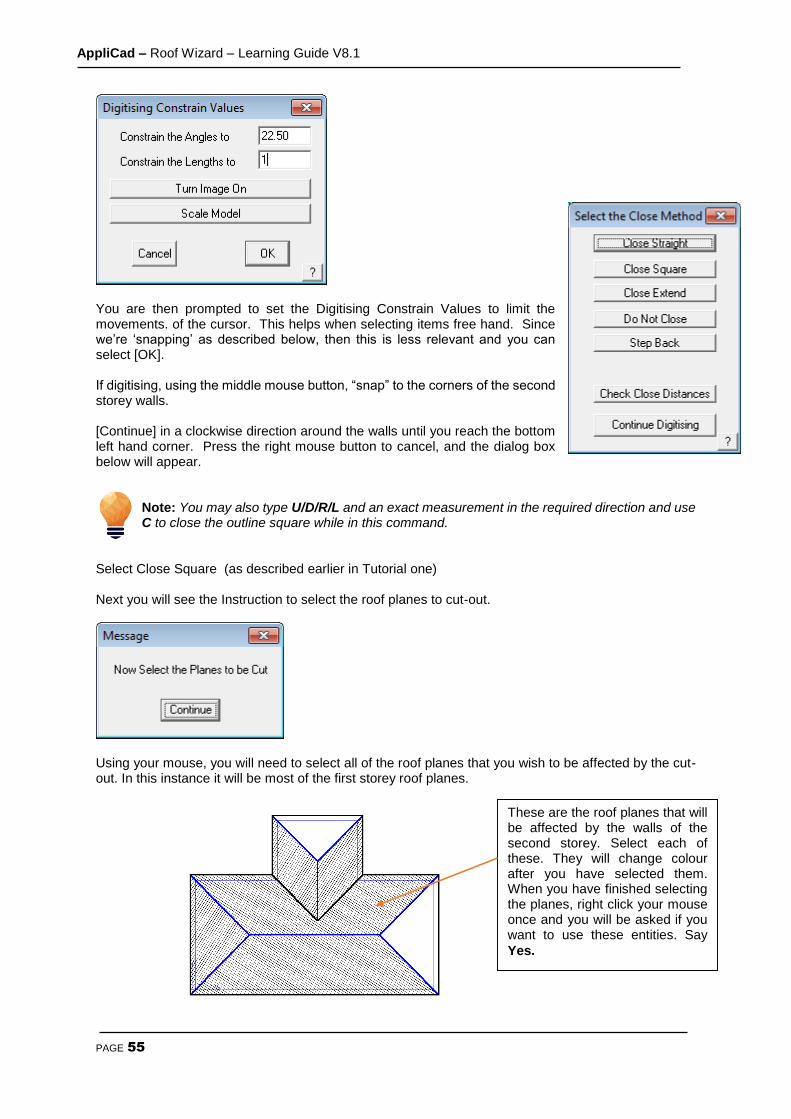
AppliCad – Roof Wizard – Learning Guide V8.1
PAGE 55
You are then prompted to set the Digitising Constrain Values to limit the movements. of the cursor. This helps when selecting items free hand. Since we’re ‘snapping’ as described below, then this is less relevant and you can select [OK]. If digitising, using the middle mouse button, “snap” to the corners of the second storey walls. [Continue] in a clockwise direction around the walls until you reach the bottom left hand corner. Press the right mouse button to cancel, and the dialog box below will appear.
Note: You may also type U/D/R/L and an exact measurement in the required direction and use C to close the outline square while in this command.
Select Close Square (as described earlier in Tutorial one) Next you will see the Instruction to select the roof planes to cut-out.
Using your mouse, you will need to select all of the roof planes that you wish to be affected by the cut-out. In this instance it will be most of the first storey roof planes.
These are the roof planes that will be affected by the walls of the second storey. Select each of these. They will change colour after you have selected them. When you have finished selecting the planes, right click your mouse once and you will be asked if you want to use these entities. Say
Yes.

AppliCad – Roof Wizard – Learning Guide V8.1
PAGE 56
The first storey roof within the selected boundary will now be automatically removed.
Your job should look like this when viewed in ISO view: (Main View Select ISO).
Exercise 25 - Modify Roof > More… > Cut-Out
The next exercise will also involve a 2 storey house, however in this case, the lower storey will be “cut in” to the second storey. We will still be using the Cutout command, but applying it in a slightly different way. Draw the second storey first, to the dimensions overleaf, with an eave overhang of 450mm and an eave height of 5000mm. Next, draw the lower storey at a height of 2400mm, using Construct-Roof > Track Outline. Use the method described above to establish the start point for the second storey as before. Then enter the values shown below. Now, when you see the Enter Wall Direction and Distance box, enter L6000 {enter} D7000 {enter} Close Square, Finish.

AppliCad – Roof Wizard – Learning Guide V8.1
PAGE 57
You should get a series of roofs looking like this:
Now proceed to remove the portion of the lower storey roof that intrudes into the upper storey area. Using Modify Roof > More…> Cut-Out, use the same settings as the previous example;
When you click [OK], select the Wall Lines of the larger roof, and then select the first storey as the storey to cut. When viewed in ISO, your plan should look like the one below.

AppliCad – Roof Wizard – Learning Guide V8.1
PAGE 58
This completes the tutorials for generating roof geometry. Now we must deal with the estimating and take-off aspects of the task. Please review the work you have completed, and when comfortable, progress to the next stage.

AppliCad – Roof Wizard – Learning Guide V8.1
PAGE 59
Cover Command For Flashings
Exercise 26 - Generating the Flashing Cutting List. This exercise deals with generating flashings or trim for the roof. If you don’t quote flashings and trim, you can skip this section. Select Cover > Flashings and the Roof flashing material dialog box will appear, listing all of the roof trim components to be specified. Only those categories of roof trim on the model will be listed in the dialog box. (We will skip battens/purlins for now, they are dealt with in the next exercise.)
Starting at the top of the Roof Trim section, select the drop down arrow Ridge. After selecting Ridge, the list of available choices for the ridge capping is displayed.

AppliCad – Roof Wizard – Learning Guide V8.1
PAGE 60
Select the required flashing item, and it will be inserted into the list. You will then be asked to select the colour of the ridge capping, if colour is to be specified. Whether colour is to be used is determined when the trim materials are initially defined. When you have chosen your colour, again press [OK]. The complete Roof Trim material dialog box will reappear. Now select the drop down arrow for Valley, Fascia, Gutter etc..

AppliCad – Roof Wizard – Learning Guide V8.1
PAGE 61
Select the required flashing item, followed by a colour. The Roof Trim material dialog box will appear. Now select Fascia. Select the required flashing item, followed by a colour. The Roof Trim material dialog box will reappear. Now select the drop down arrow for Valley, Fascia, Gutter etc.. After you have set up all of the flashing/trim options, your Roof Trim material dialog box will look like the one above. Select [OK] to confirm your selections. If you use this combination of roof trim often, you may save the selection as a default selection, saving the time to reselect them next job. You will get a prompt as shown below; type a meaningful name and click [OK]. This definition will be saved for future use.

AppliCad – Roof Wizard – Learning Guide V8.1
PAGE 62
You can define the estimation method for each flashing in the Set-Up > Flashings menu (refer to the Reference Manual or setup guide). This ensures that the flashing items and their associated accessories such as end caps, splice plates and brackets etc. will be correctly quantified. Flashings may be supplied (and therefore quantified) based on stock lengths or cut to length, as one would if you have a continuous gutter machine.

AppliCad – Roof Wizard – Learning Guide V8.1
PAGE 63
Exercise 27 - Inserting Purlins/Battens (For Metal Roofs) Please note that battens and purlins are essentially the same thing with a different name in different markets. To insert battens on our job we need to select the Batten drop down arrow option on the Flashing dialog box.
From here select the required purlin or batten followed by [OK]. This will then take you back to the select Flashing dialog box. The next step is to select the Insert/Modify button at the right hand side of the battens field. This will then bring up the Batten Spacings dialog box.
Note: These battens are used for metal roofing only. For tile roofing, the battens are selected and applied when selecting the Tile within the Cover > Tile command.
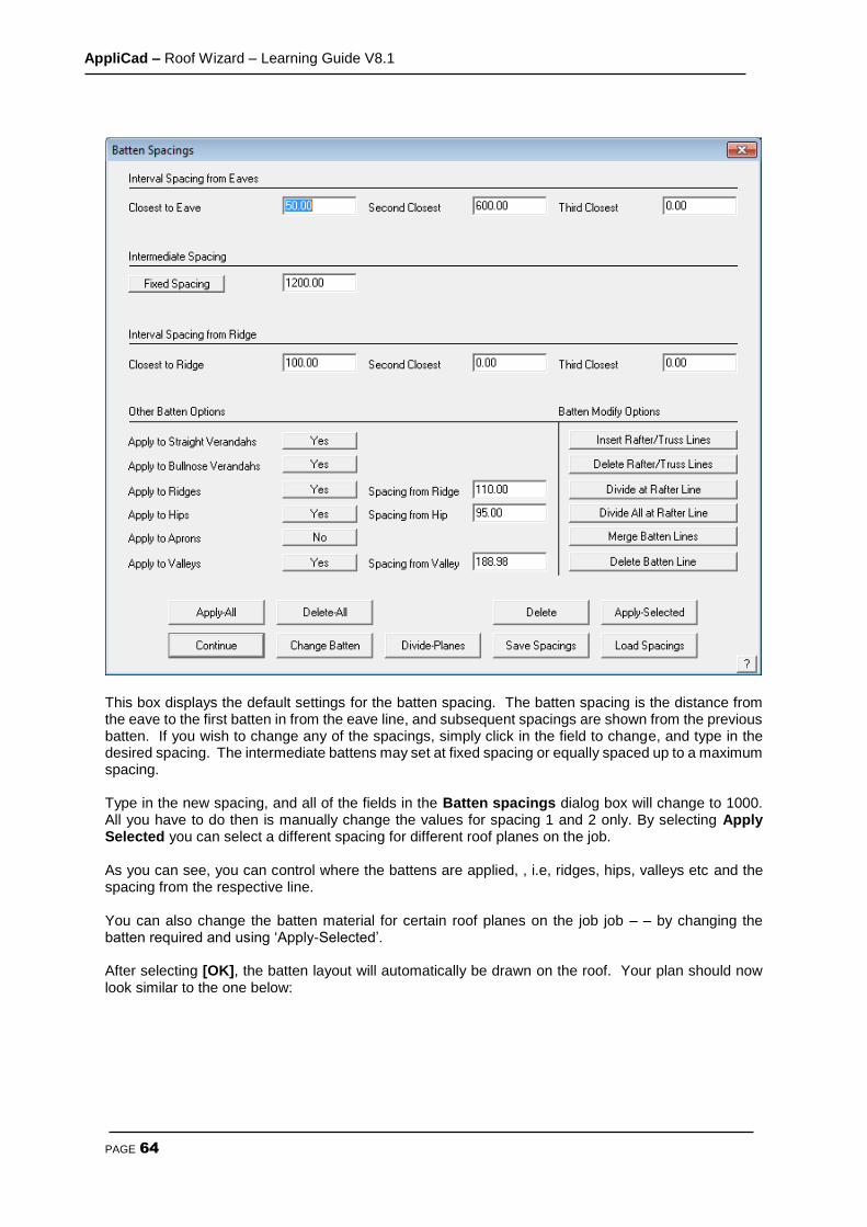
AppliCad – Roof Wizard – Learning Guide V8.1
PAGE 64
This box displays the default settings for the batten spacing. The batten spacing is the distance from the eave to the first batten in from the eave line, and subsequent spacings are shown from the previous batten. If you wish to change any of the spacings, simply click in the field to change, and type in the desired spacing. The intermediate battens may set at fixed spacing or equally spaced up to a maximum spacing. Type in the new spacing, and all of the fields in the Batten spacings dialog box will change to 1000. All you have to do then is manually change the values for spacing 1 and 2 only. By selecting Apply Selected you can select a different spacing for different roof planes on the job. As you can see, you can control where the battens are applied, , i.e, ridges, hips, valleys etc and the spacing from the respective line. You can also change the batten material for certain roof planes on the job job – – by changing the batten required and using ‘Apply-Selected’. After selecting [OK], the batten layout will automatically be drawn on the roof. Your plan should now look similar to the one below:
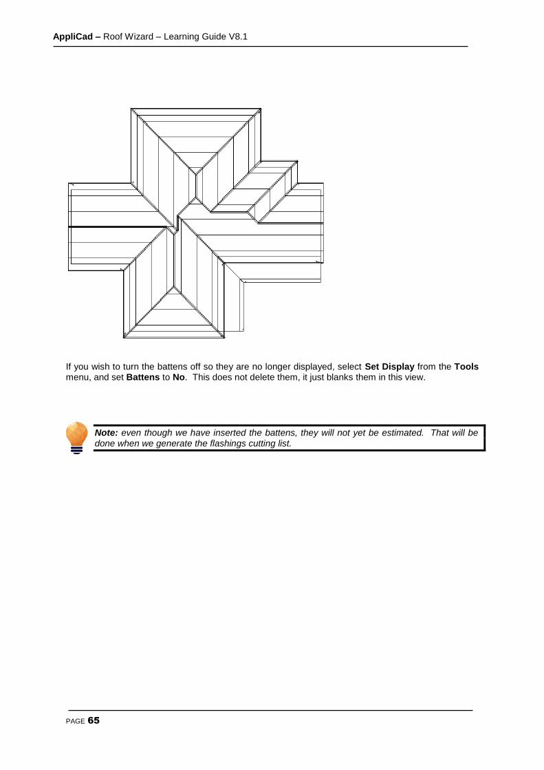
AppliCad – Roof Wizard – Learning Guide V8.1
PAGE 65
If you wish to turn the battens off so they are no longer displayed, select Set Display from the Tools menu, and set Battens to No. This does not delete them, it just blanks them in this view.
Note: even though we have inserted the battens, they will not yet be estimated. That will be done when we generate the flashings cutting list.
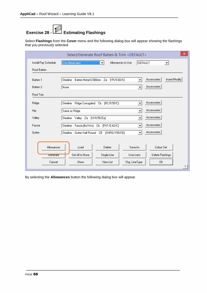
AppliCad – Roof Wizard – Learning Guide V8.1
PAGE 66
Exercise 28 - Estimating Flashings Select Flashings from the Cover menu and the following dialog box will appear showing the flashings that you previously selected.
By selecting the Allowances button the following dialog box will appear.
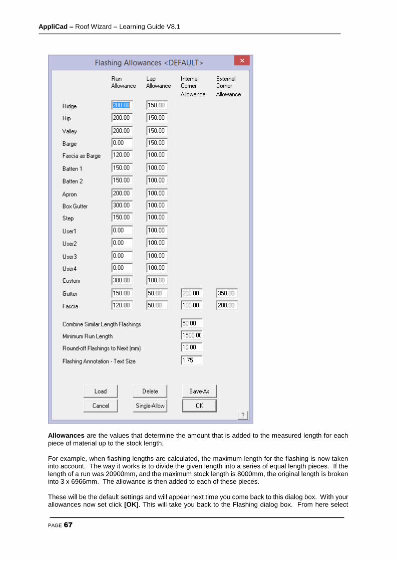
AppliCad – Roof Wizard – Learning Guide V8.1
PAGE 67
Allowances are the values that determine the amount that is added to the measured length for each piece of material up to the stock length. For example, when flashing lengths are calculated, the maximum length for the flashing is now taken into account. The way it works is to divide the given length into a series of equal length pieces. If the length of a run was 20900mm, and the maximum stock length is 8000mm, the original length is broken into 3 x 6966mm. The allowance is then added to each of these pieces. These will be the default settings and will appear next time you come back to this dialog box. With your allowances now set click [OK]. This will take you back to the Flashing dialog box. From here select
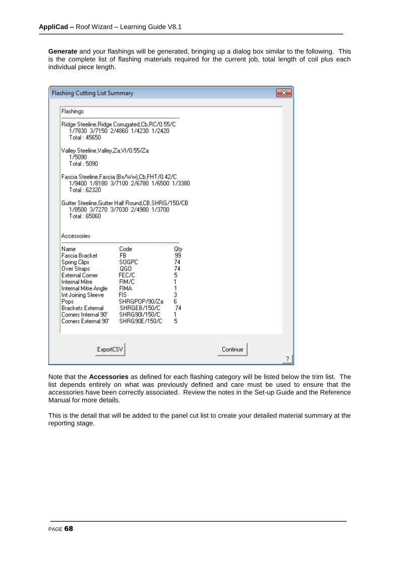
AppliCad – Roof Wizard – Learning Guide V8.1
PAGE 68
Generate and your flashings will be generated, bringing up a dialog box similar to the following. This is the complete list of flashing materials required for the current job, total length of coil plus each individual piece length.
Note that the Accessories as defined for each flashing category will be listed below the trim list. The list depends entirely on what was previously defined and care must be used to ensure that the accessories have been correctly associated. Review the notes in the Set-up Guide and the Reference Manual for more details. This is the detail that will be added to the panel cut list to create your detailed material summary at the reporting stage.

AppliCad – Roof Wizard – Learning Guide V8.1
PAGE 69
The Cover Command - Tile Roofs
Introduction
Quantity by Coursing or Unit Area - Tiles and Tiles+ Database
Before going ahead and select your tiles for the roof, you have to decide the best method of
determining the tile quantities. You have the choice of generating tile quantities by unit area (ie
tiles per square metre) or the more precise method of coursing which lays the tiles course by
course and applies a more flexible waste calculation.
In addition you have two tile database structures that you can work with – what AppliCad calls
Tiles database and the Tiles+ database.
The Tiles+ database is a comprehensive database of tiles and accessories plus components,
that is most suited to the UK and European markets, where-as the Tiles database is a much
simplified tile database generally suitable for the Australian and USA markets.
Once you have decided which database structure best suits you (call AppliCad if you’re not sure),
you set the database type using Set-Up > System Preferences. Now you are ready to quantify
your tiles. Section 3 explains the differences in more detail.
The Cover command lets you select new tiles, shingles or shakes for this job. You can also apply sarking and generate tile courses.
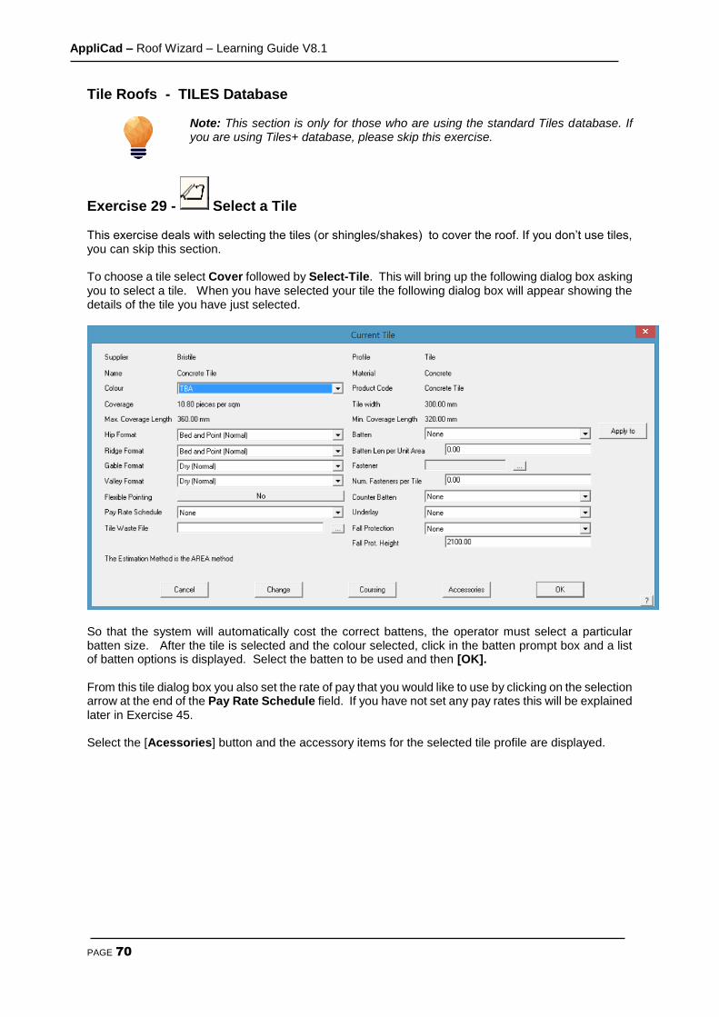
AppliCad – Roof Wizard – Learning Guide V8.1
PAGE 70
Tile Roofs - TILES Database
Note: This section is only for those who are using the standard Tiles database. If you are using Tiles+ database, please skip this exercise.
Exercise 29 - Select a Tile This exercise deals with selecting the tiles (or shingles/shakes) to cover the roof. If you don’t use tiles, you can skip this section. To choose a tile select Cover followed by Select-Tile. This will bring up the following dialog box asking you to select a tile. When you have selected your tile the following dialog box will appear showing the details of the tile you have just selected.
So that the system will automatically cost the correct battens, the operator must select a particular batten size. After the tile is selected and the colour selected, click in the batten prompt box and a list of batten options is displayed. Select the batten to be used and then [OK]. From this tile dialog box you also set the rate of pay that you would like to use by clicking on the selection arrow at the end of the Pay Rate Schedule field. If you have not set any pay rates this will be explained later in Exercise 45. Select the [Acessories] button and the accessory items for the selected tile profile are displayed.
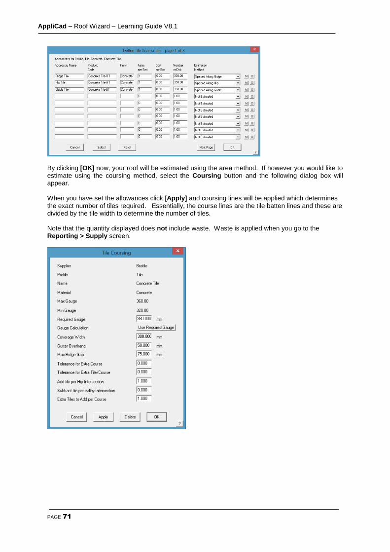
AppliCad – Roof Wizard – Learning Guide V8.1
PAGE 71
By clicking [OK] now, your roof will be estimated using the area method. If however you would like to estimate using the coursing method, select the Coursing button and the following dialog box will appear. When you have set the allowances click [Apply] and coursing lines will be applied which determines the exact number of tiles required. Essentially, the course lines are the tile batten lines and these are divided by the tile width to determine the number of tiles. Note that the quantity displayed does not include waste. Waste is applied when you go to the Reporting > Supply screen.
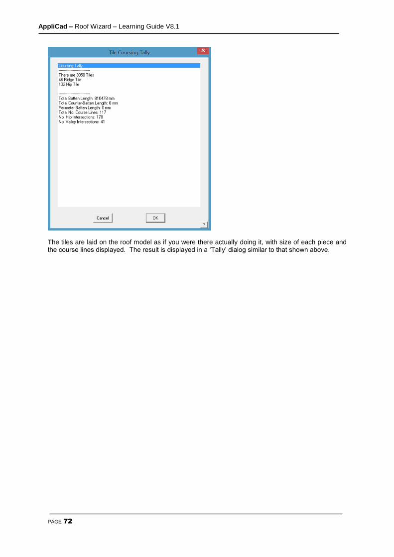
AppliCad – Roof Wizard – Learning Guide V8.1
PAGE 72
The tiles are laid on the roof model as if you were there actually doing it, with size of each piece and the course lines displayed. The result is displayed in a ‘Tally’ dialog similar to that shown above.
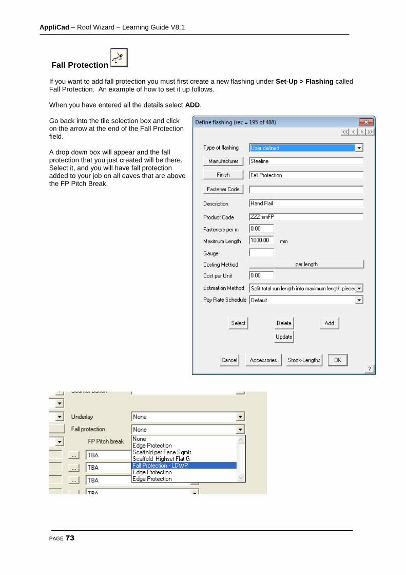
AppliCad – Roof Wizard – Learning Guide V8.1
PAGE 73
Fall Protection If you want to add fall protection you must first create a new flashing under Set-Up > Flashing called Fall Protection. An example of how to set it up follows. When you have entered all the details select ADD. Go back into the tile selection box and click on the arrow at the end of the Fall Protection field. A drop down box will appear and the fall protection that you just created will be there. Select it, and you will have fall protection added to your job on all eaves that are above the FP Pitch Break.
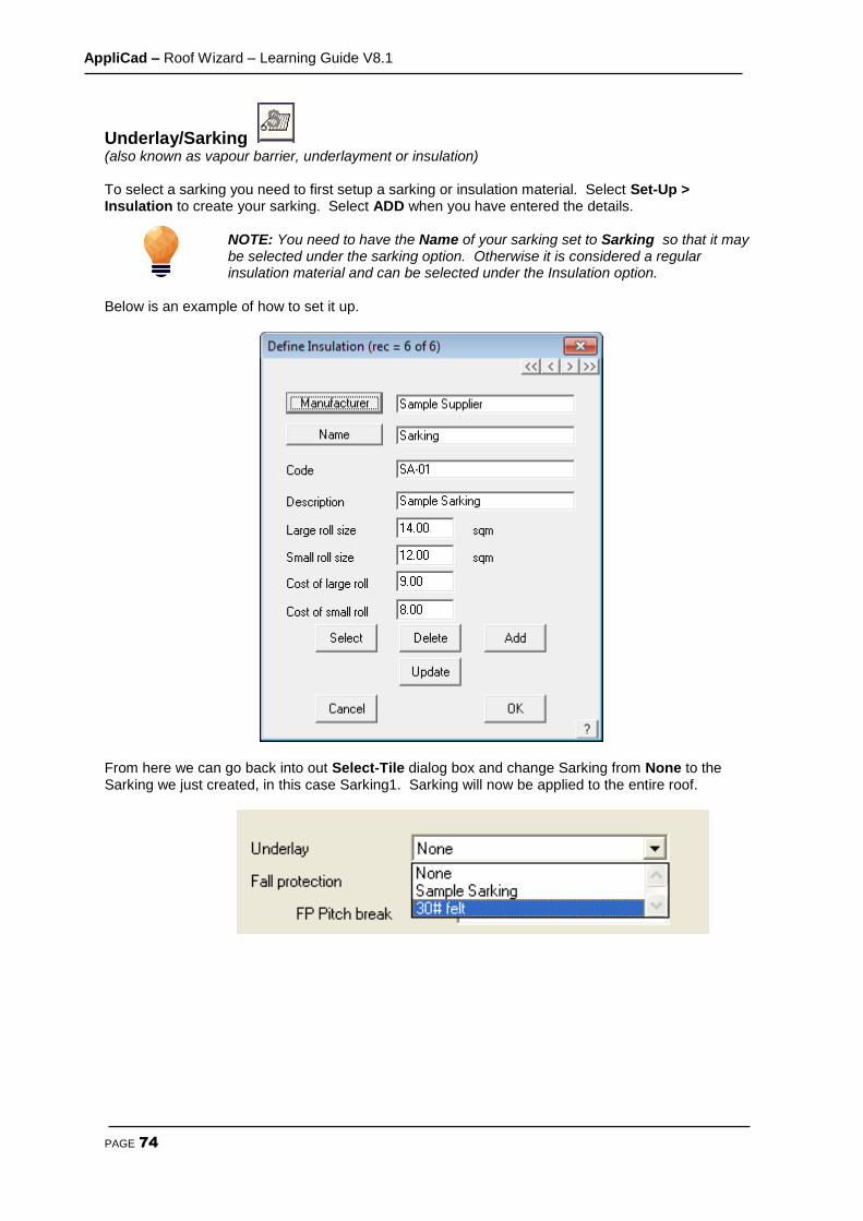
AppliCad – Roof Wizard – Learning Guide V8.1
PAGE 74
Underlay/Sarking (also known as vapour barrier, underlayment or insulation) To select a sarking you need to first setup a sarking or insulation material. Select Set-Up > Insulation to create your sarking. Select ADD when you have entered the details.
NOTE: You need to have the Name of your sarking set to Sarking so that it may be selected under the sarking option. Otherwise it is considered a regular insulation material and can be selected under the Insulation option.
Below is an example of how to set it up.
From here we can go back into out Select-Tile dialog box and change Sarking from None to the Sarking we just created, in this case Sarking1. Sarking will now be applied to the entire roof.
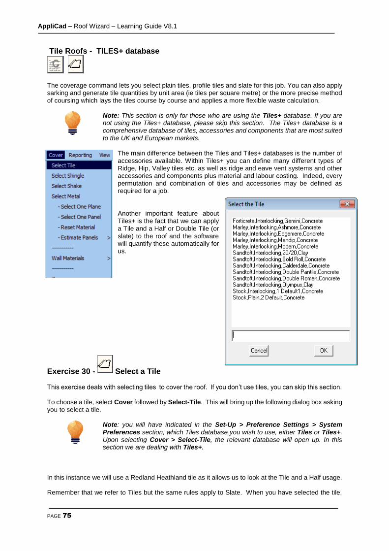
AppliCad – Roof Wizard – Learning Guide V8.1
PAGE 75
Tile Roofs - TILES+ database
The coverage command lets you select plain tiles, profile tiles and slate for this job. You can also apply sarking and generate tile quantities by unit area (ie tiles per square metre) or the more precise method of coursing which lays the tiles course by course and applies a more flexible waste calculation.
Note: This section is only for those who are using the Tiles+ database. If you are not using the Tiles+ database, please skip this section. The Tiles+ database is a comprehensive database of tiles, accessories and components that are most suited to the UK and European markets.
The main difference between the Tiles and Tiles+ databases is the number of accessories available. Within Tiles+ you can define many different types of Ridge, Hip, Valley tiles etc, as well as ridge and eave vent systems and other accessories and components plus material and labour costing. Indeed, every permutation and combination of tiles and accessories may be defined as required for a job. Another important feature about Tiles+ is the fact that we can apply a Tile and a Half or Double Tile (or slate) to the roof and the software will quantify these automatically for us.
Exercise 30 - Select a Tile This exercise deals with selecting tiles to cover the roof. If you don’t use tiles, you can skip this section. To choose a tile, select Cover followed by Select-Tile. This will bring up the following dialog box asking you to select a tile.
Note: you will have indicated in the Set-Up > Preference Settings > System Preferences section, which Tiles database you wish to use, either Tiles or Tiles+. Upon selecting Cover > Select-Tile, the relevant database will open up. In this section we are dealing with Tiles+.
In this instance we will use a Redland Heathland tile as it allows us to look at the Tile and a Half usage. Remember that we refer to Tiles but the same rules apply to Slate. When you have selected the tile,
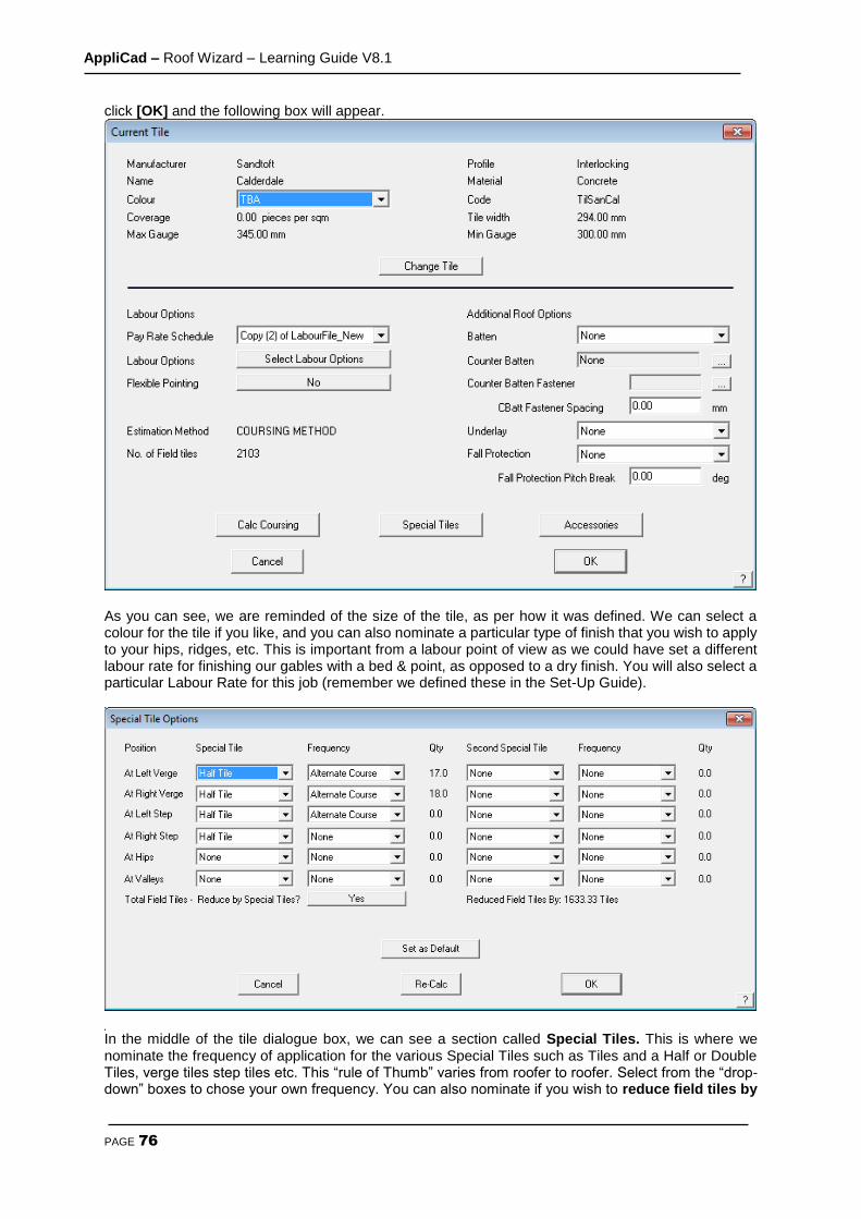
AppliCad – Roof Wizard – Learning Guide V8.1
PAGE 76
click [OK] and the following box will appear.
As you can see, we are reminded of the size of the tile, as per how it was defined. We can select a colour for the tile if you like, and you can also nominate a particular type of finish that you wish to apply to your hips, ridges, etc. This is important from a labour point of view as we could have set a different labour rate for finishing our gables with a bed & point, as opposed to a dry finish. You will also select a particular Labour Rate for this job (remember we defined these in the Set-Up Guide).
In the middle of the tile dialogue box, we can see a section called Special Tiles. This is where we nominate the frequency of application for the various Special Tiles such as Tiles and a Half or Double Tiles, verge tiles step tiles etc. This “rule of Thumb” varies from roofer to roofer. Select from the “drop-down” boxes to chose your own frequency. You can also nominate if you wish to reduce field tiles by

AppliCad – Roof Wizard – Learning Guide V8.1
PAGE 77
tile + half pieces? This means that you can either quantify for the tile and a halves in addition to the field tiles on the roof (as if there were no tile and a halves), or reduce the field tiles by the correct amount for a more accurate quotation. You may set the definition as a default so it available for the next job. On the bottom left of the Tiles page, we have the Coursing section. Here is where we can change the coursing values for that tile if required, as well as specify a Gutter Overhang and Ridge Gap. Normally the software will Use best fit gauge to quantify the courses up each slope, but if you needed to, you can “force” the gauge by entering a value in the Required Gauge field (as long as it is between the max and min gauge range). If you wished to do this, you would change the Gauge Calculation to read Use Required Gauge. If you use a Required Gauge the software mathematically works out the number of courses and number of tile widths by dividing the gauge into slope length and eave length. There may be times when the software will round up to the next number of courses or next tile width, which may cause you to over-quantify the number of tiles. To alleviate this problem, we have included the ability to set a Tolerance for both “Courses” and “width” so that if you specify a tolerance of say “0.2” and the software calculates that there are 45.18 courses on a slope, it will round it down to 45 courses, rather than round it up. When you have input the required settings, click on Apply Coursing and you will see that there are a series of lines applied to the roof – these are the actual coursing lines. A value will appear next to the Field Tiles from area field. This is the quantity of tiles required before waste is applied.
Note, if you have elected to use the area method to calculate the tiles – select Calculate Using Area but this will not quantify the tile and a halves or some other accessories. You set the starting preference (Coursing or by Area in the Tools > Preferences option).
When you defined the tile, you may have already defined a size of batten that you would normally use, in which case, that would be indicated here. You can also change that selection on a job-by-job basis. You will also select your material for your Sarking (insulation or underlay). When you have made this selection, select Accessories to nominate the accessories to accompany the tile. When you click
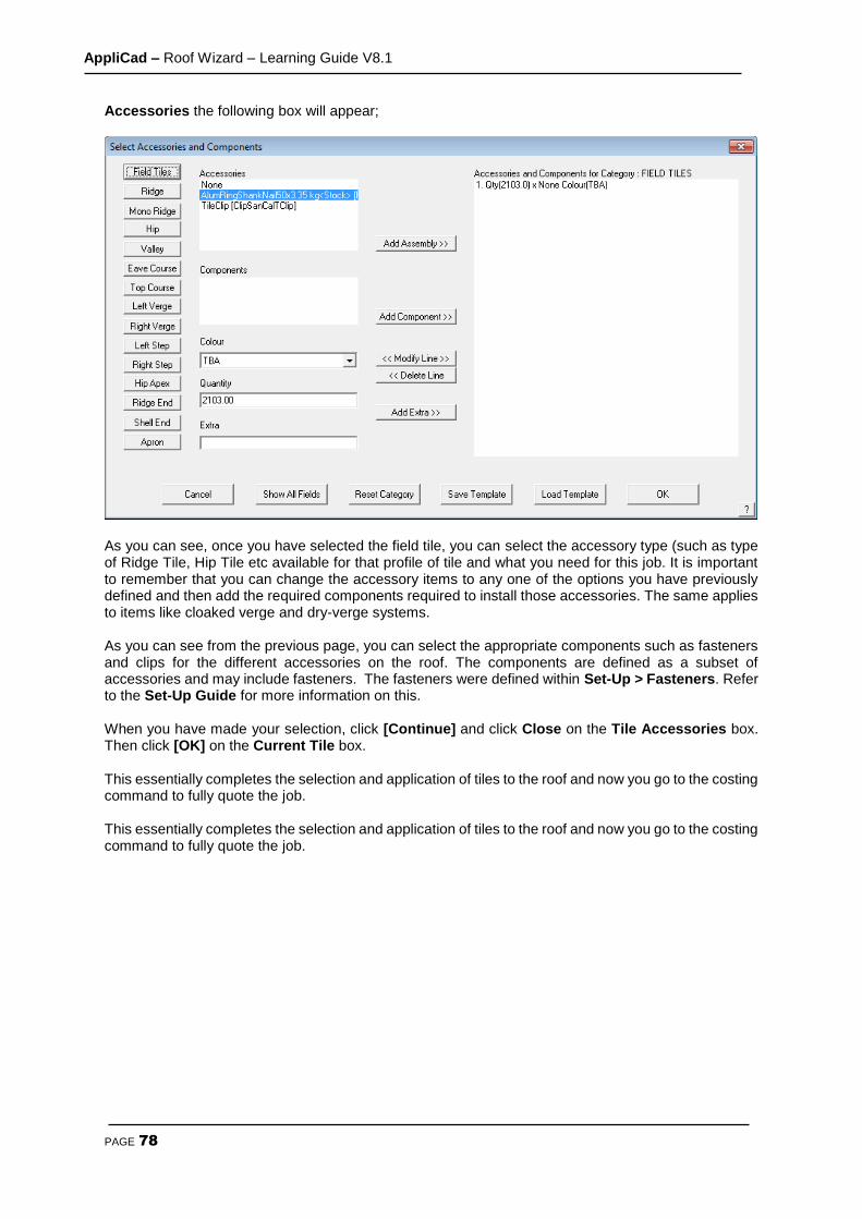
AppliCad – Roof Wizard – Learning Guide V8.1
PAGE 78
Accessories the following box will appear;
As you can see, once you have selected the field tile, you can select the accessory type (such as type of Ridge Tile, Hip Tile etc available for that profile of tile and what you need for this job. It is important to remember that you can change the accessory items to any one of the options you have previously defined and then add the required components required to install those accessories. The same applies to items like cloaked verge and dry-verge systems. As you can see from the previous page, you can select the appropriate components such as fasteners and clips for the different accessories on the roof. The components are defined as a subset of accessories and may include fasteners. The fasteners were defined within Set-Up > Fasteners. Refer to the Set-Up Guide for more information on this. When you have made your selection, click [Continue] and click Close on the Tile Accessories box. Then click [OK] on the Current Tile box. This essentially completes the selection and application of tiles to the roof and now you go to the costing command to fully quote the job. This essentially completes the selection and application of tiles to the roof and now you go to the costing command to fully quote the job.

AppliCad – Roof Wizard – Learning Guide V8.1
PAGE 79
The Cover Command - Metal Roofing
Exercise 31 - Selecting the Metal Coverage Selecting Cover from the Main menu, brings up the menu at the right. To specify the roof covering for our model, select Select-Metal from the menu. The Select Roof Material dialog is displayed with the default settings in the sort criteria of All. As each option is selected, the data filter displays the remaining material options that fit that criteria, often resulting in just the oine option that meets your needs.
The dialog box below will appear listing all available sheeting materials. The material list is created during setup, however new materials may be added at any time. This is done through the Set-Up menu option on the Main menu. For more details refer to Section 5. The products listed may be filtered by selecting either Supplier, Profile, Gauge, Finish and Coverage so that by elimination, only those options that fit the specification are displayed.
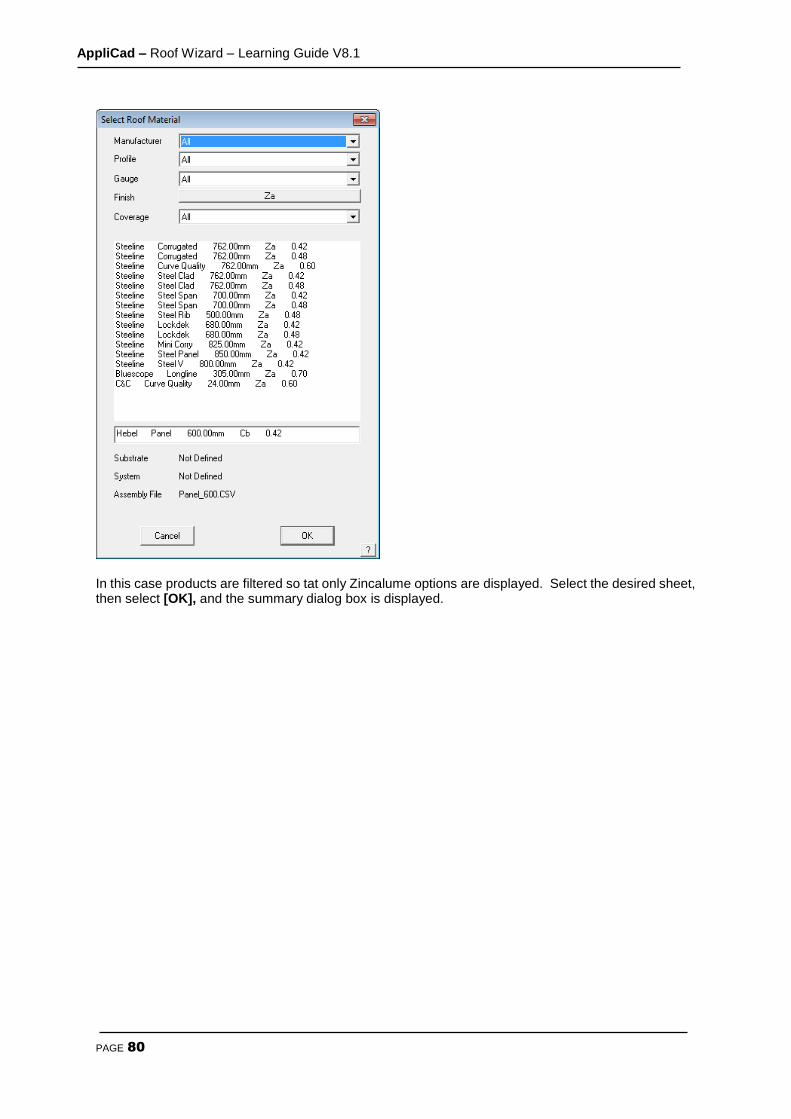
AppliCad – Roof Wizard – Learning Guide V8.1
PAGE 80
In this case products are filtered so tat only Zincalume options are displayed. Select the desired sheet, then select [OK], and the summary dialog box is displayed.

AppliCad – Roof Wizard – Learning Guide V8.1
PAGE 81
The next dialog to appear will prompt you to select a colour for the particular metal sheeting that you have nominated, if it is specified to be a painted product. Select any colour at this time. Your selection will now appear at the bottom of the dialog box. Select [OK]. After the colour has been selected, the roof cover material dialog box will come up, detailing the sheeting you have selected, its colour, product code, and associated fastener (which was set when the sheet was defined).

AppliCad – Roof Wizard – Learning Guide V8.1
PAGE 82
At this point, you can also amend your selection by clicking on the change button for either straight or curved roofing. Bullnose verandahs will automatically adopt the curved material you have selected. If a job has more than one type of sheeting, the option Cover > Select Metal > One-Plane is selected. This allows you to change the profile and/or colour for a specific area of the roof. You can also set the properties of a single roof sheet using the option Cover > Select Metal > One-Panel, and this will be covered later. To specify the material for a bullnose verandah select Change from the right hand side, or Curving Side of the previous dialog box. Select the required Curving Quality panel and click [OK]. The attributes for the selected panel will appear on the previous dialog box on the right hand side.
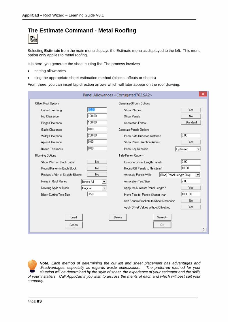
AppliCad – Roof Wizard – Learning Guide V8.1
PAGE 83
The Estimate Command - Metal Roofing
Selecting Estimate from the main menu displays the Estimate menu as displayed to the left. This menu option only applies to metal roofing. It is here, you generate the sheet cutting list. The process involves
setting allowances
sing the appropriate sheet estimation method (blocks, offcuts or sheets)
From there, you can insert lap direction arrows which will later appear on the roof drawing.
Note: Each method of determining the cut list and sheet placement has advantages and disadvantages, especially as regards waste optimization. The preferred method for your situation will be determined by the style of sheet, the experience of your estimator and the skills
of your installers. Call AppliCad if you wish to discuss the merits of each and which will best suit your company.
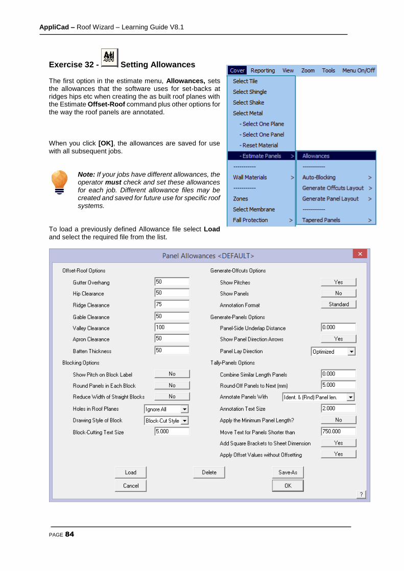
AppliCad – Roof Wizard – Learning Guide V8.1
PAGE 84
Exercise 32 - Setting Allowances The first option in the estimate menu, Allowances, sets the allowances that the software uses for set-backs at ridges hips etc when creating the as built roof planes with the Estimate Offset-Roof command plus other options for the way the roof panels are annotated. When you click [OK], the allowances are saved for use with all subsequent jobs.
Note: If your jobs have different allowances, the operator must check and set these allowances for each job. Different allowance files may be created and saved for future use for specific roof systems.
To load a previously defined Allowance file select Load and select the required file from the list.
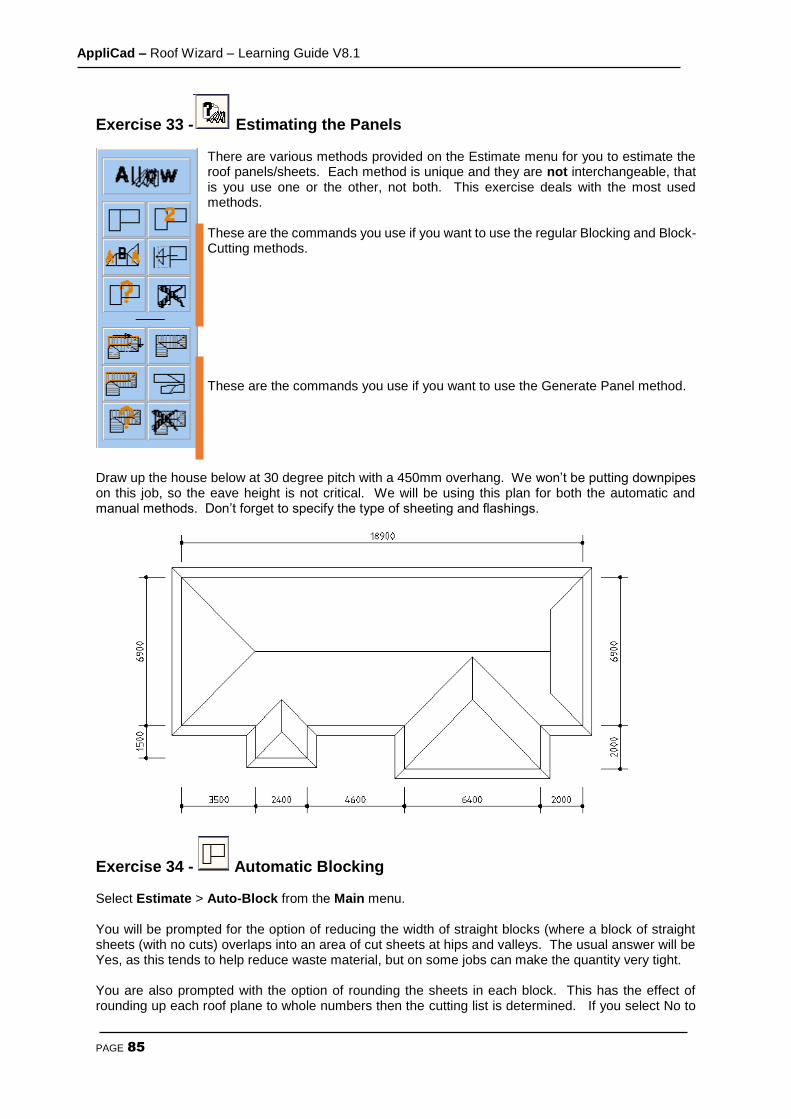
AppliCad – Roof Wizard – Learning Guide V8.1
PAGE 85
Exercise 33 - Estimating the Panels There are various methods provided on the Estimate menu for you to estimate the roof panels/sheets. Each method is unique and they are not interchangeable, that is you use one or the other, not both. This exercise deals with the most used methods. These are the commands you use if you want to use the regular Blocking and Block-Cutting methods. These are the commands you use if you want to use the Generate Panel method.
Draw up the house below at 30 degree pitch with a 450mm overhang. We won’t be putting downpipes on this job, so the eave height is not critical. We will be using this plan for both the automatic and manual methods. Don’t forget to specify the type of sheeting and flashings.
Exercise 34 - Automatic Blocking Select Estimate > Auto-Block from the Main menu. You will be prompted for the option of reducing the width of straight blocks (where a block of straight sheets (with no cuts) overlaps into an area of cut sheets at hips and valleys. The usual answer will be Yes, as this tends to help reduce waste material, but on some jobs can make the quantity very tight. You are also prompted with the option of rounding the sheets in each block. This has the effect of rounding up each roof plane to whole numbers then the cutting list is determined. If you select No to

AppliCad – Roof Wizard – Learning Guide V8.1
PAGE 86
this option, the rounding is done once all the roof sheets of a particular length have been determined. This has the effect of reducing the number of sheets in a job, thus reducing waste. It assumes that the installers are mindful of re-using off-cuts to reduce waste instead of throwing off-cuts into the scrap bin.
The software will now automatically insert cross-hatched rectangles or ‘blocks’ over the entire roof area. Each block will contain the number of sheets in the block, the length of the sheets and also confirms the pitch. The fat orange line you see on screen indicates the bottome edge of the sheets. Therefore, a block designated 8 x3150 (22.5) indicates 8 sheets at 3150mm long on a pitch of 22.5 degrees. Your roof plan should now look like the one below.
It must be noted that the effective utilization of the sheets as determined by the blocking method is very much dependent upon the skill of the installers, especially on a more complex roof shape. The software does allow for modification of the blocks in the case where an experienced operator can see a more effective block layout than that produced by the software. This is covered in the Reference Manual . The next step is to view the results of the automatic blocking in the form of the Sheet cutting list summary dialog box. Select Tally-Blocks from the Estimate menu to create a sheet cutting list summary. The dialog box below will appear. It provides the sheet cutting list and a summary of the Roof Area and the Sheet Area and Total Sheet Length (the amount of coil required from your inventory).

AppliCad – Roof Wizard – Learning Guide V8.1
PAGE 87
This completes the section on the automatic blocking method. If you wish to make any changes on an automatically created block layout, there are commands available to make these modifications. These will be covered in the following section where will look at inserting blocks manually.
Exercise 35 - Manual Blocking As mentioned previously, we will be using the same roof plan that we used for the automatic method. The aim of this exercise is to come up with exactly the same answer as the automatic method.

AppliCad – Roof Wizard – Learning Guide V8.1
PAGE 88
Select Cover > Estimate Panels >Auto-Blocking > Modify Block from the Estimate menu. The menu at left will appear.
We will now go through the two methods used to insert a block onto a roof panel. These are Insert-Rect and Insert-Line. To describe these two methods we will insert the long rectangular block at the top of the plan. It is then up to you which method you use to complete the blocking. In some instances it may be easier to use a combination of both these methods. We’ll look at the rectangle method first. Select Insert-Rect from the Blocks menu. You will then be asked to select the line which determines the direction of the block. For this case we will use D3. When you have selected the corresponding line, the dialog box below will appear asking you to select the storey for the roof. This is a single storey house, so select [OK].
This will then bring up the following dialog box asking you for the pitch of the roof. Type in 30, as this is the pitch of the roof we are using.
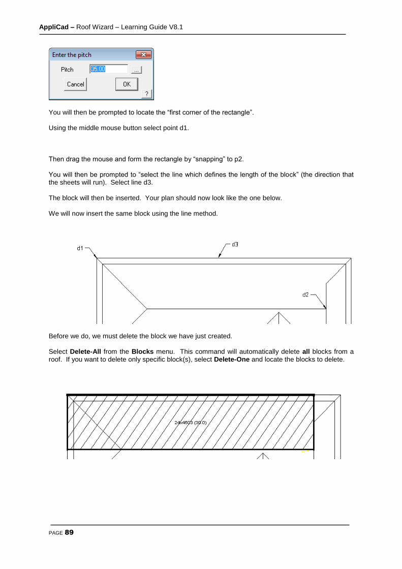
AppliCad – Roof Wizard – Learning Guide V8.1
PAGE 89
You will then be prompted to locate the “first corner of the rectangle”. Using the middle mouse button select point d1. Then drag the mouse and form the rectangle by “snapping” to p2. You will then be prompted to “select the line which defines the length of the block” (the direction that the sheets will run). Select line d3. The block will then be inserted. Your plan should now look like the one below. We will now insert the same block using the line method.
Before we do, we must delete the block we have just created. Select Delete-All from the Blocks menu. This command will automatically delete all blocks from a roof. If you want to delete only specific block(s), select Delete-One and locate the blocks to delete.

AppliCad – Roof Wizard – Learning Guide V8.1
PAGE 90
Select Insert-Line from the Blocks menu. You will then be asked to select the line which determines the direction of the block. For this case we will use the line D2. When you have selected the corresponding line the following dialog box will appear asking for the pitch of the roof. Enter 30.
You will then be prompted to “locate a line to generate a block”. Select line d1.
A hatched square will appear over the hip end. You will then be prompted to “select the line which defines the length of the block”. Select line d2. Your plan should now look like the one at right. The next step is to “extend” the right hand edge of this block so it covers the same area as was created using the automatic method. Select Extend-Edge. You will then be prompted to “ locate a line to move”. Select line d3. You will then be prompted to “locate its new position:”. Snap to point d4. The block will now automatically extend to this point, and the text inside will be updated.
Your plan should now look the one below.

AppliCad – Roof Wizard – Learning Guide V8.1
PAGE 91
[Continue] inserting the remainder of the blocks using whatever method you prefer.
Note: The method of extending edges as described above, can be used to “push and pull” the edges of blocks that have been created using the automatic method.
This concludes the section on the blocking method of estimating roof panels/sheets..
Exercise 36 - Set Panels (Lap Direction) Notice that the Estimate > Generate Panel Layout > Set Plane Parameters command has an option for inserting the lap direction of the sheets. This is particularly important in areas of high wind. Most suppliers also specify the lap direction with respect to prevailing winds and their warranty is only valid if the roof has been fixed with this in mind. Note that when you select and insert a panel a lap direction is automatically inserted if you haven’t specified it already. To insert lap direction arrows, select Lap-Ins-Dir-Auto. If the lap direction that has been inserted is incorrect you can change then by selecting Swap-Lap-Dir. For example:
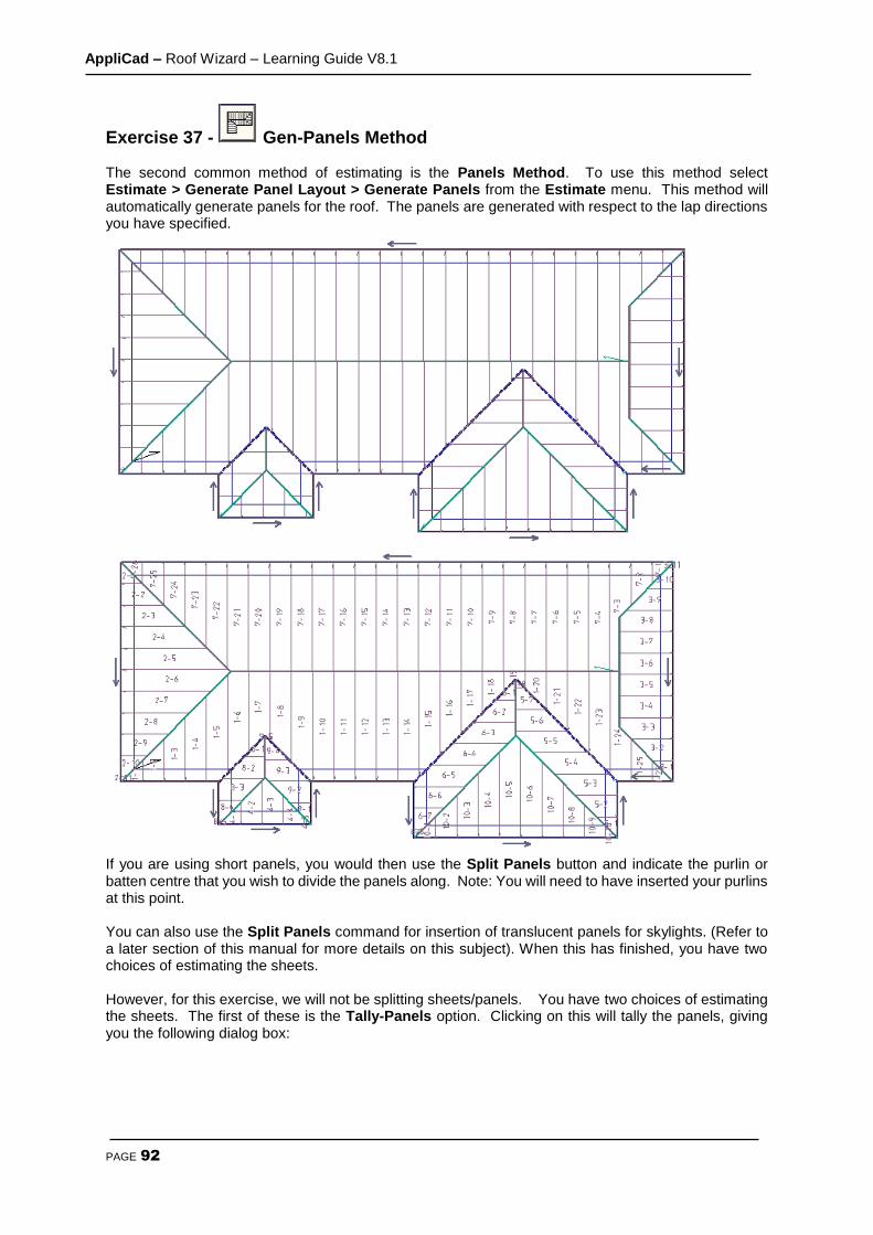
AppliCad – Roof Wizard – Learning Guide V8.1
PAGE 92
Exercise 37 - Gen-Panels Method The second common method of estimating is the Panels Method. To use this method select Estimate > Generate Panel Layout > Generate Panels from the Estimate menu. This method will automatically generate panels for the roof. The panels are generated with respect to the lap directions you have specified.
If you are using short panels, you would then use the Split Panels button and indicate the purlin or batten centre that you wish to divide the panels along. Note: You will need to have inserted your purlins at this point. You can also use the Split Panels command for insertion of translucent panels for skylights. (Refer to a later section of this manual for more details on this subject). When this has finished, you have two choices of estimating the sheets. However, for this exercise, we will not be splitting sheets/panels. You have two choices of estimating the sheets. The first of these is the Tally-Panels option. Clicking on this will tally the panels, giving you the following dialog box:
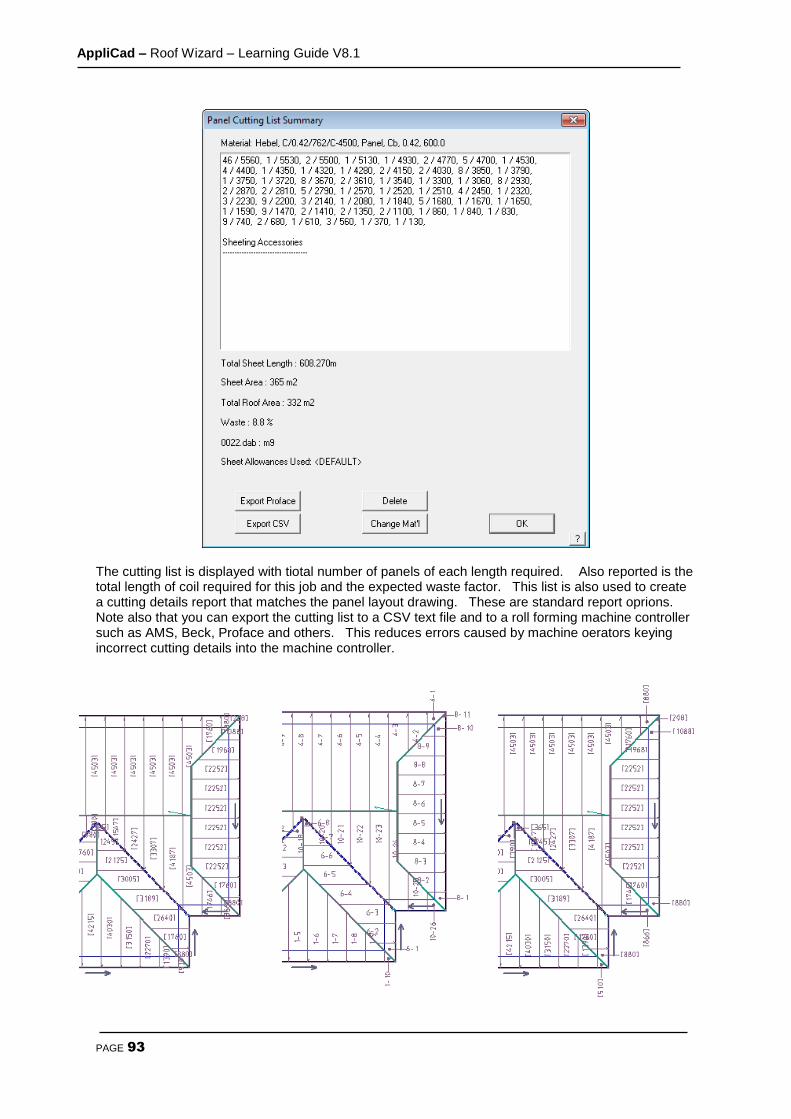
AppliCad – Roof Wizard – Learning Guide V8.1
PAGE 93
The cutting list is displayed with tiotal number of panels of each length required. Also reported is the total length of coil required for this job and the expected waste factor. This list is also used to create a cutting details report that matches the panel layout drawing. These are standard report oprions. Note also that you can export the cutting list to a CSV text file and to a roll forming machine controller such as AMS, Beck, Proface and others. This reduces errors caused by machine oerators keying incorrect cutting details into the machine controller.
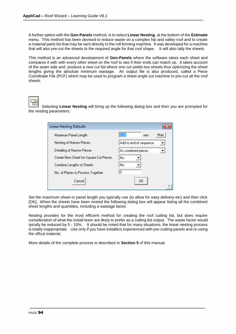
AppliCad – Roof Wizard – Learning Guide V8.1
PAGE 94
A further option with the Gen-Panels method, is to select Linear Nesting, at the bottom of the Estimate menu. This method has been devised to reduce waste on a complex hip and valley roof and to create a material parts list that may be sent directly to the roll forming machine. It was developed for a machine that will also pre-cut the sheets to the required angle for that roof shape. It will also tally the sheets. This method is an advanced development of Gen-Panels where the software takes each sheet and compares it with with every other sheet on the roof to see if their ends can match up. It takes account of the seam side and produce a new cut list where one cut yields two sheets thus optimizing the sheet lengths giving the absolute minimum wastage. An output file is also produced, called a Piece Coordinate File (PCF) which may be used to program a sheet angle cut machine to pre-cut all the roof sheets.
Selecting Linear Nesting will bring up the following dialog box and then you are prompted for the nesting parameters:
Set the maximum sheet or panel length you typically use (to allow for easy delivery etc) and then click [OK]. When the sheets have been nested the following dialog box will appear listing all the combined sheet lengths and quantities, including a wastage factor. Nesting provides for the most efficient method for creating the roof cutting list, but does require consideration of what the install team are likely to prefer as a cutting list output. The waste factor would tyically be reduced by 5 - 10%. It should be noted that for many situations, the linear nesting process is totally inappropriate. Use only if you have installers experienced with pre-cutting panels and re-using the offcut material. More details of the complete process is described in Section 5 of this manual.
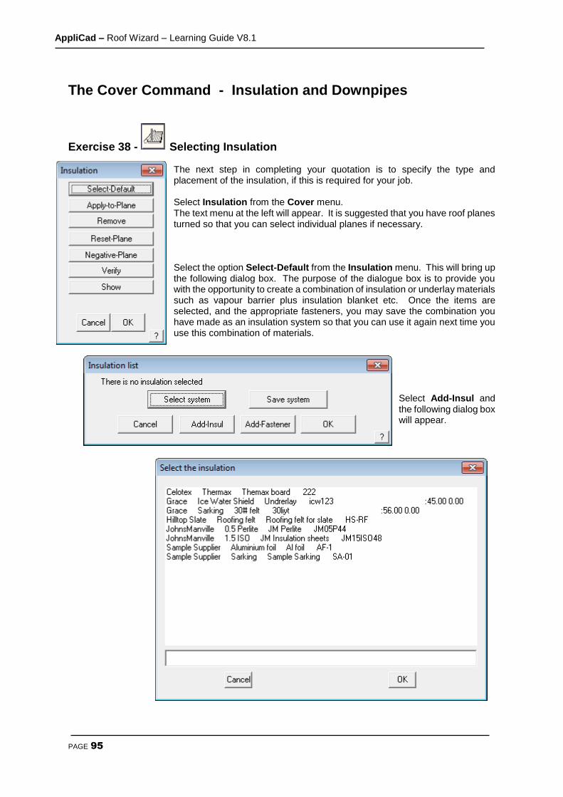
AppliCad – Roof Wizard – Learning Guide V8.1
PAGE 95
The Cover Command - Insulation and Downpipes
Exercise 38 - Selecting Insulation The next step in completing your quotation is to specify the type and placement of the insulation, if this is required for your job. Select Insulation from the Cover menu. The text menu at the left will appear. It is suggested that you have roof planes turned so that you can select individual planes if necessary. Select the option Select-Default from the Insulation menu. This will bring up the following dialog box. The purpose of the dialogue box is to provide you with the opportunity to create a combination of insulation or underlay materials such as vapour barrier plus insulation blanket etc. Once the items are selected, and the appropriate fasteners, you may save the combination you have made as an insulation system so that you can use it again next time you use this combination of materials.
Select Add-Insul and the following dialog box will appear.
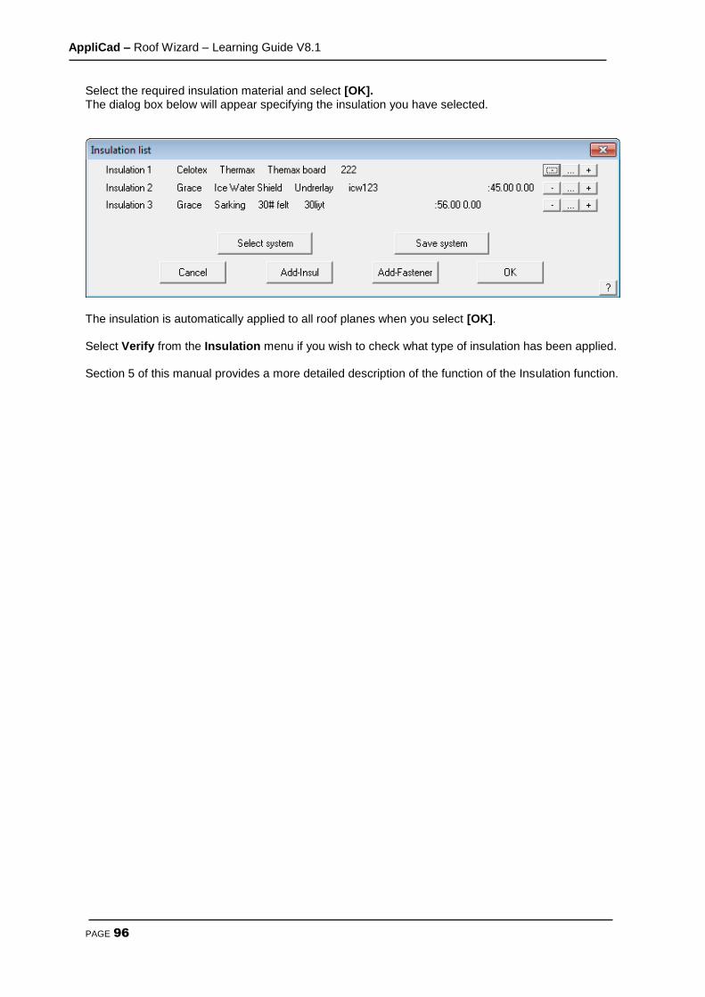
AppliCad – Roof Wizard – Learning Guide V8.1
PAGE 96
Select the required insulation material and select [OK]. The dialog box below will appear specifying the insulation you have selected.
The insulation is automatically applied to all roof planes when you select [OK]. Select Verify from the Insulation menu if you wish to check what type of insulation has been applied. Section 5 of this manual provides a more detailed description of the function of the Insulation function.

AppliCad – Roof Wizard – Learning Guide V8.1
PAGE 97
Exercise 39 - Selecting Downpipes The last step that remains to be done as far as your roof cover quotation is concerned, is to specify the position and type of down pipes. Select Down pipes from the Coverage menu. The Select new DownPipe dialog box will appear.
Select the required downpipe select [OK]. The Select new colour dialog box will appear. Select any colour and select [OK]. Now that we have specified the type of down pipe we will be using, the next step is to position them around the structure. You will now be prompted to Locate a line to insert the down pipe on. Using the left mouse button, locate an eave line, remembering that where you select the line will be the position of the down pipe. Position the down pipes as per the drawing below.
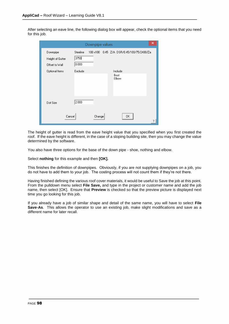
AppliCad – Roof Wizard – Learning Guide V8.1
PAGE 98
After selecting an eave line, the following dialog box will appear, check the optional items that you need for this job.
The height of gutter is read from the eave height value that you specified when you first created the roof. If the eave height is different, in the case of a sloping building site, then you may change the value determined by the software. You also have three options for the base of the down pipe - shoe, nothing and elbow. Select nothing for this example and then [OK]. This finishes the definition of downpipes. Obviously, if you are not supplying downpipes on a job, you do not have to add them to your job. The costing process will not count them if they’re not there. Having finished defining the various roof cover materials, it would be useful to Save the job at this point. From the pulldown menu select File Save, and type in the project or customer name and add the job name, then select [OK]. Ensure that Preview is checked so that the preview picture is displayed next time you go looking for this job. If you already have a job of similar shape and detail of the same name, you will have to select File Save-As. This allows the operator to use an existing job, make slight modifications and save as a different name for later recall.

AppliCad – Roof Wizard – Learning Guide V8.1
PAGE 99
The Cover Command – BUR/Single Ply Roofing
The roof assembly we will be drawing, is a multi-layered structure made up of several discrete plies, with the following specifications:
1 layer of JM ISO 40mm 1 layer of JM Perlite 10mm Mechanically fastened with screws and plates – 2 every 1 sqm Layer of ashphalt at 10 kgs per 30 sqm 1 layer of JM Glass 6 Layer of ashphalt at 10 kgs per 30 sqm 1 layer of JM Glass 6 Layer of ashphalt at 10 kgs per 30 sqm 1 layer of JM Glass 6 Layer of ashphalt at 14 kgs per 30 sqm 1 layer of JM glass cap
Our roof structure for this exercise will be a concrete slab with a parapet wall around all sides 1 meter high. The edge detail all around is:
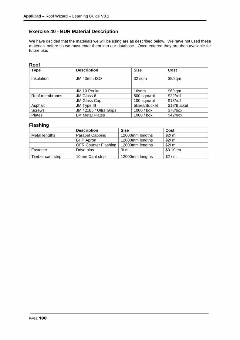
AppliCad – Roof Wizard – Learning Guide V8.1
PAGE 100
Exercise 40 - BUR Material Description We have decided that the materials we will be using are as described below. We have not used these materials before so we must enter them into our database. Once entered they are then available for future use.
Roof Type Description Size Cost
Insulation JM 40mm ISO 32 sqm $8/sqm
JM 10 Perlite 16sqm $6/sqm
Roof membranes JM Glass 6 500 sqm/roll $22/roll
JM Glass Cap 100 sqm/roll $13/roll
Asphalt JM Type III 5litres/Bucket $13/Bucket
Screws JM 12x65 “ Ultra Grips 1000 / box $78/box
Plates LM Metal Plates 1000 / box $42/box
Flashing Description Size Cost
Metal lengths Parapet Capping 12000mm lengths $2/ m
BHP Apron 12000mm lengths $2/ m
OFR Counter Flashing 12000mm lengths $2/ m
Fastener Drive pins 3/ m $0.10 ea
Timber cant strip 10mm Cant strip 12000mm lengths $2 / m

AppliCad – Roof Wizard – Learning Guide V8.1
PAGE 101
Exercise 41 - Define the Roof Outline Draw up the following flat roof using the command Construct-Roof > Track-Outline from the main menu. The Track-Outline and select ‘flat roof’ and the command generates an outline without hips and and valleys.
The Construct-Roof > Track Outline - Plane outline generator dialog looks like the illustration below, and allows you to input the perimeter dimensions and direction by clicking the direction buttons. You may also simply type r70000 for a line created to the right, 70 meters (70000mm) long. Once you get to the second last perimeter line, simply select C {enter} or Close and Close Square. The system will automatically compute the correct geometry to close the perimeter and draw the remaining outline. Check that the last two dimensions are correct. If they are, then you may proceed to the next step. At this stage the lines are construction lines only and don’t really exist, until we select F {enter} or Finish on the dialog box.
If they are not correct, then the information is incorrect or you made a mistake in setting the perimeter dimensions. In the event of a mistake, select Stepback until you delete the wrong line and re-insert it. Once complete with cross-hatching to represent our roof surface, you are ready to get a roof geometry summary immediately. Select Tools > Tally-Quantities from the main menu and the result is

AppliCad – Roof Wizard – Learning Guide V8.1
PAGE 102
displayed.
Exercise 42 - Apply the Roof Insulation We now need to select materials and apply them to our roof as a roof material system that is made up of various plies. Working up from the roof base, we will select each material in turn. While the order does not matter from a take-off point of view, it certainly helps in the interpretation to have the materials listed in the order they are to be laid. We will start with the underlay.
Using the command from the main menu Cover > Insulation > Select-default, select the types of insulation and the screws and plates with the Add-Insul and Add-Fastener buttons. Since it is likely you will use this same order of material in the future, you may save it as a “system” so that you can recall it again pre-defined. To save it select the Save System button and type in a system name to describe it when prompted. Notice on the right hand side of this dialog box three buttons. These are used to delete, change a line item relating to that material ply or add a ply before the line item.
Exercise 43 - Apply the Roof Material. When you have defined your insulation, select [OK], to finish and go to the next step, which is to add the roof cover material – the Built Up Roof system. Using Cover > Select-Membrane > Select-Default, select the plies and fasteners (asphalt) as you did for insulation. You may also save a set of plies as a roof system. To do this, select Save System and give it a name so that it can be easily identified and used again.
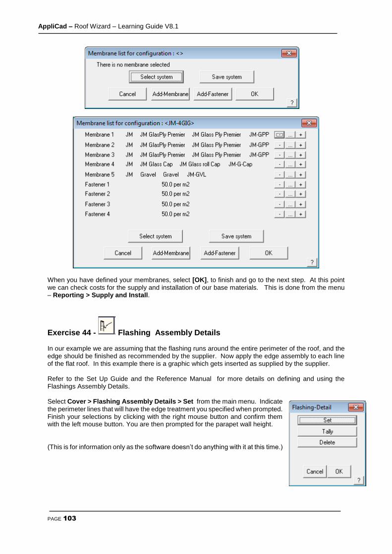
AppliCad – Roof Wizard – Learning Guide V8.1
PAGE 103
When you have defined your membranes, select [OK], to finish and go to the next step. At this point we can check costs for the supply and installation of our base materials. This is done from the menu – Reporting > Supply and Install.
Exercise 44 - Flashing Assembly Details In our example we are assuming that the flashing runs around the entire perimeter of the roof, and the edge should be finished as recommended by the supplier. Now apply the edge assembly to each line of the flat roof. In this example there is a graphic which gets inserted as supplied by the supplier. Refer to the Set Up Guide and the Reference Manual for more details on defining and using the Flashings Assembly Details. Select Cover > Flashing Assembly Details > Set from the main menu. Indicate the perimeter lines that will have the edge treatment you specified when prompted. Finish your selections by clicking with the right mouse button and confirm them with the left mouse button. You are then prompted for the parapet wall height. (This is for information only as the software doesn’t do anything with it at this time.)

AppliCad – Roof Wizard – Learning Guide V8.1
PAGE 104
The edge or Flashing Assembly Detail is automatically drawn where you indicate and will be added to all subsequent reports when they are printed. If all your materials have been correctly specified, when you select Cover > Flashing details > Tally you will get a dialog similar to the following. It is a summary of all the trim that is required to waterproof the Flashing Assembly.
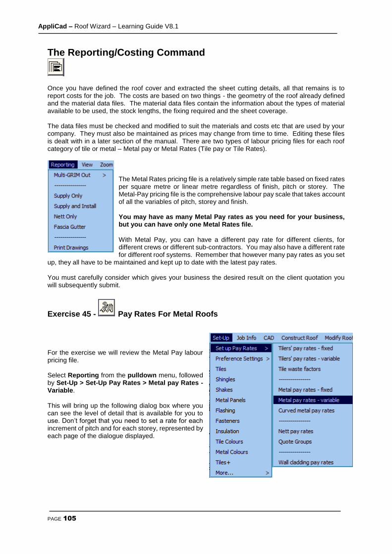
AppliCad – Roof Wizard – Learning Guide V8.1
PAGE 105
The Reporting/Costing Command
Once you have defined the roof cover and extracted the sheet cutting details, all that remains is to report costs for the job. The costs are based on two things - the geometry of the roof already defined and the material data files. The material data files contain the information about the types of material available to be used, the stock lengths, the fixing required and the sheet coverage. The data files must be checked and modified to suit the materials and costs etc that are used by your company. They must also be maintained as prices may change from time to time. Editing these files is dealt with in a later section of the manual. There are two types of labour pricing files for each roof category of tile or metal – Metal pay or Metal Rates (Tile pay or Tile Rates).
The Metal Rates pricing file is a relatively simple rate table based on fixed rates per square metre or linear metre regardless of finish, pitch or storey. The Metal-Pay pricing file is the comprehensive labour pay scale that takes account of all the variables of pitch, storey and finish. You may have as many Metal Pay rates as you need for your business, but you can have only one Metal Rates file. With Metal Pay, you can have a different pay rate for different clients, for different crews or different sub-contractors. You may also have a different rate for different roof systems. Remember that however many pay rates as you set
up, they all have to be maintained and kept up to date with the latest pay rates. You must carefully consider which gives your business the desired result on the client quotation you will subsequently submit.
Exercise 45 - Pay Rates For Metal Roofs For the exercise we will review the Metal Pay labour pricing file. Select Reporting from the pulldown menu, followed by Set-Up > Set-Up Pay Rates > Metal pay Rates - Variable. This will bring up the following dialog box where you can see the level of detail that is available for you to use. Don’t forget that you need to set a rate for each increment of pitch and for each storey, represented by each page of the dialogue displayed.

AppliCad – Roof Wizard – Learning Guide V8.1
PAGE 106
From here you can enter your pay rates for different pitches and stories. Name your pay sheet and select Add. This pay rate will now be added to the database. This does not mean you have selected a pay rate for your job. You select the required pay rate for your job when you select the material to be applied on the Cover > Select-Metal dialog box. For a detailed description of setup and use of these options, refer to the Reference Manual.
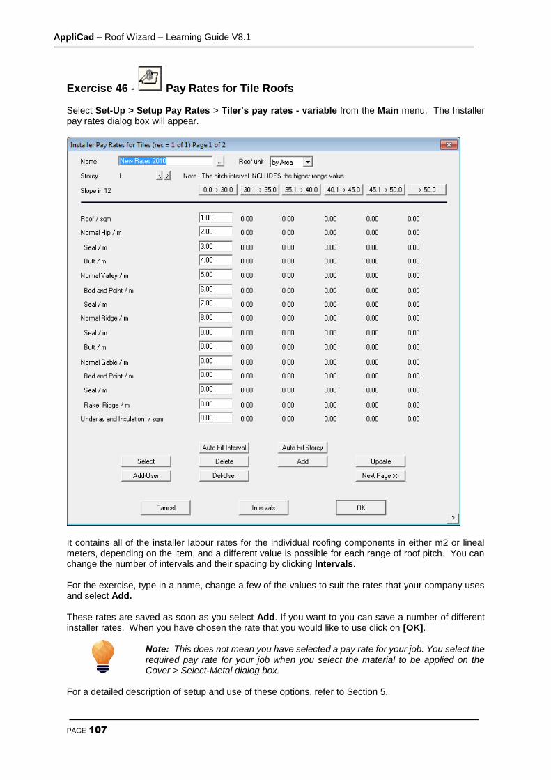
AppliCad – Roof Wizard – Learning Guide V8.1
PAGE 107
Exercise 46 - Pay Rates for Tile Roofs Select Set-Up > Setup Pay Rates > Tiler’s pay rates - variable from the Main menu. The Installer pay rates dialog box will appear.
It contains all of the installer labour rates for the individual roofing components in either m2 or lineal meters, depending on the item, and a different value is possible for each range of roof pitch. You can change the number of intervals and their spacing by clicking Intervals. For the exercise, type in a name, change a few of the values to suit the rates that your company uses and select Add. These rates are saved as soon as you select Add. If you want to you can save a number of different installer rates. When you have chosen the rate that you would like to use click on [OK].
Note: This does not mean you have selected a pay rate for your job. You select the required pay rate for your job when you select the material to be applied on the Cover > Select-Metal dialog box.
For a detailed description of setup and use of these options, refer to Section 5.
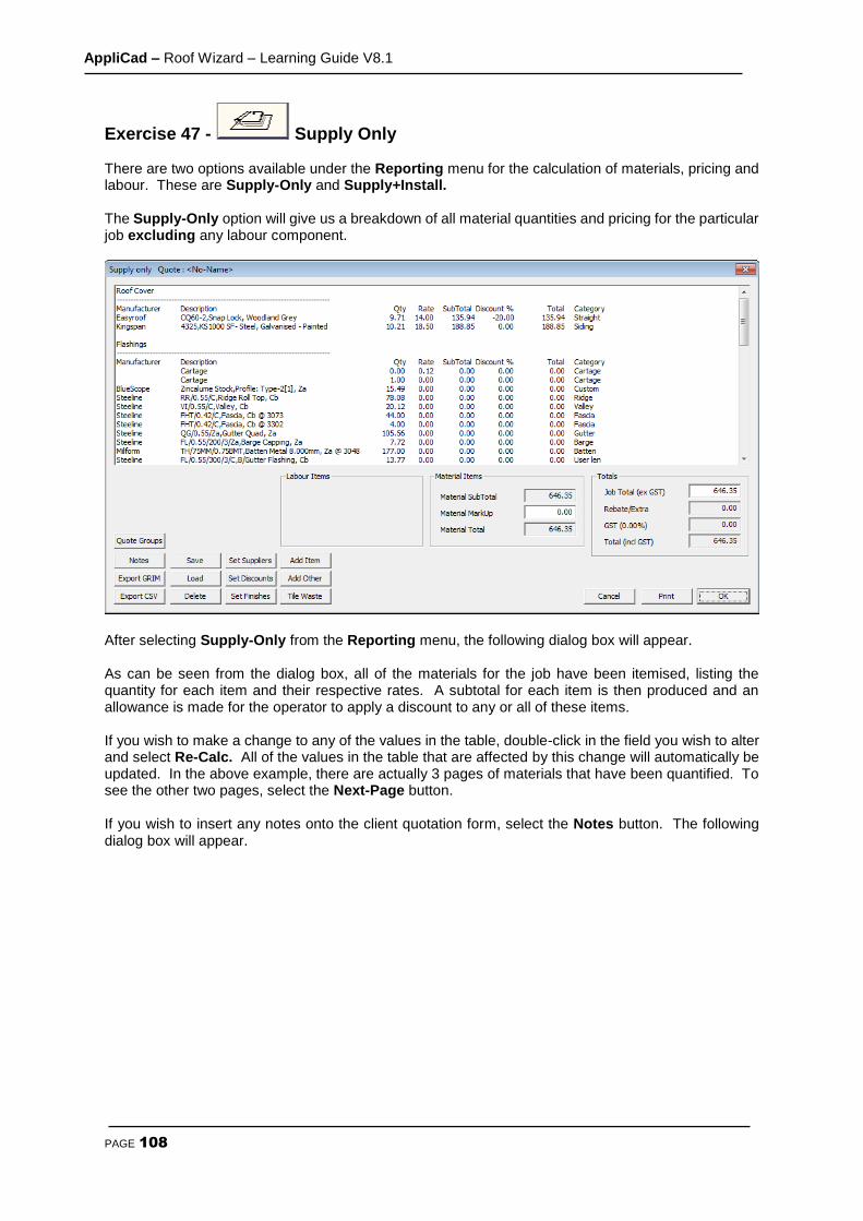
AppliCad – Roof Wizard – Learning Guide V8.1
PAGE 108
Exercise 47 - Supply Only There are two options available under the Reporting menu for the calculation of materials, pricing and labour. These are Supply-Only and Supply+Install. The Supply-Only option will give us a breakdown of all material quantities and pricing for the particular job excluding any labour component.
After selecting Supply-Only from the Reporting menu, the following dialog box will appear. As can be seen from the dialog box, all of the materials for the job have been itemised, listing the quantity for each item and their respective rates. A subtotal for each item is then produced and an allowance is made for the operator to apply a discount to any or all of these items. If you wish to make a change to any of the values in the table, double-click in the field you wish to alter and select Re-Calc. All of the values in the table that are affected by this change will automatically be updated. In the above example, there are actually 3 pages of materials that have been quantified. To see the other two pages, select the Next-Page button. If you wish to insert any notes onto the client quotation form, select the Notes button. The following dialog box will appear.

AppliCad – Roof Wizard – Learning Guide V8.1
PAGE 109
From here select the form that you would like to add notes to, bringing up the following dialog box.
Selecting the Add-Predef-Note allows you to select from a list of pre-defined notes:
Selecting Check/Add Notes allows you to modify or add to the selected notes that will be inserted on the quotation or proposal.

AppliCad – Roof Wizard – Learning Guide V8.1
PAGE 110
Finishing and Saving Proposal Once you are happy with all of the values, and you’ve given yourself a hefty profit, the next step is to save the particular quote under an easily recognizable name, as our client may want us to quote on more than one profile for the same job.
Select Save. The dialog box below will appear. Type in the desired quote name and select [OK]. Use this to keep track of the proposal. You might be asked to prepare an alternate proposal for different materials or different finish.. The Supply-Only Quote dialog box will now reappear. The Quote name appears in the title bar at the top of the dialog box. The complete set of job pricing information is then saved into the model database and writes the name of the quote to a file saved in the \User folder called QuoteRegister.csv so that the job may be recalled by quote number from the File menu.
To print out this particular quote, select Print and the customer quotation and all of the details in the
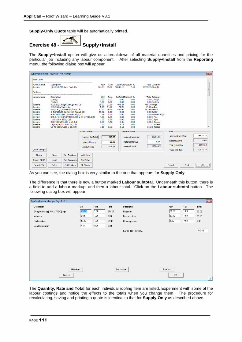
AppliCad – Roof Wizard – Learning Guide V8.1
PAGE 111
Supply-Only Quote table will be automatically printed.
Exercise 48 - Supply+Install The Supply+Install option will give us a breakdown of all material quantities and pricing for the particular job including any labour component. After selecting Supply+Install from the Reporting menu, the following dialog box will appear.
As you can see, the dialog box is very similar to the one that appears for Supply-Only. The difference is that there is now a button marked Labour subtotal. Underneath this button, there is a field to add a labour markup, and then a labour total. Click on the Labour subtotal button. The following dialog box will appear.
The Quantity, Rate and Total for each individual roofing item are listed. Experiment with some of the labour costings and notice the effects to the totals when you change them. The procedure for recalculating, saving and printing a quote is identical to that for Supply-Only as described above.

AppliCad – Roof Wizard – Learning Guide V8.1
PAGE 112
Exercise 49 - Printing Reports To print your quotes. Select print from the Supply + Install dialog box and the following dialog box will appear.
Select the reports that you would like to print by double clicking the required drawing to Print, and then select [OK]. At this point the software will retrieve the drawing of the roof and insert the relevant information in accordance with the information set up in Job Info e.g. site address etc. and any other information that you may have specified to appear on the report or drawing by way of key text strings. This process will be visible on the screen. The Windows Print dialog box will then appear. If we had a printer connected, we would select [OK], and the required report will be printed automatically. After the report has been printed, the roof model will be redrawn on the screen.
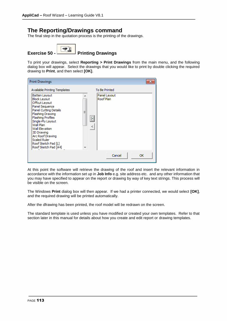
AppliCad – Roof Wizard – Learning Guide V8.1
PAGE 113
The Reporting/Drawings command The final step in the quotation process is the printing of the drawings.
Exercise 50 - Printing Drawings To print your drawings, select Reporting > Print Drawings from the main menu, and the following dialog box will appear. Select the drawings that you would like to print by double clicking the required drawing to Print, and then select [OK].
At this point the software will retrieve the drawing of the roof and insert the relevant information in accordance with the information set up in Job Info e.g. site address etc. and any other information that you may have specified to appear on the report or drawing by way of key text strings. This process will be visible on the screen. The Windows Print dialog box will then appear. If we had a printer connected, we would select [OK], and the required drawing will be printed automatically. After the dfrawing has been printed, the roof model will be redrawn on the screen. The standard template is used unless you have modified or created your own templates. Refer to that section later in this manual for details about how you create and edit report or drawing templates.

AppliCad – Roof Wizard – Learning Guide V8.1
PAGE 114
Wall Creation and Modification The purpose of the following tutorial is to familiarize you with the process of creating a wall in 3D from an Architectural drawing. The Walls option may not be available if you have not purchased the Walls module. The modelling tutorials will be divided into two sections. The first section will explain how to use the Track-Walls command, and the second will explain about Projecting Walls from either the outline we have drawn, or from a Roofing job already completed.
This will be followed by tutorials on coverage and costing. Before we start we make sure that your Preferences are set to Metric, English and Degrees. This is set under the Set-Up > Preference Settings > System Preferences menu.
Exercise 1 - Track-Outline First select the Walls option from the Main menu We will use Track-Walls to input a wall outline as this will be the most usual method of outline definition. Imagine we have received a job to cost via the fax. The drawing is fully dimensioned. Select Track-Walls . A horizontal and vertical line will appear on the screen forming a cross. The intersection of these two lines is the point used for plotting or locating various points. At the bottom of the screen in the prompt area, it will ask you to Locate start point. This works in the same way as when using our roofing software. Using the left mouse button, locate a point anywhere on the screen. The Wall Direction and distance dialog box will now appear. (see below) :
The buttons marked Left, Right, Up and Down, allow you to navigate around the plan as you put in the external brickwork measurements. The angled lines are for walls that are at 45 degrees. The Hor-Ver button is to allow the operator to insert wall lines that are not square with the balance of the structure ie 2000 along and 3500 up.
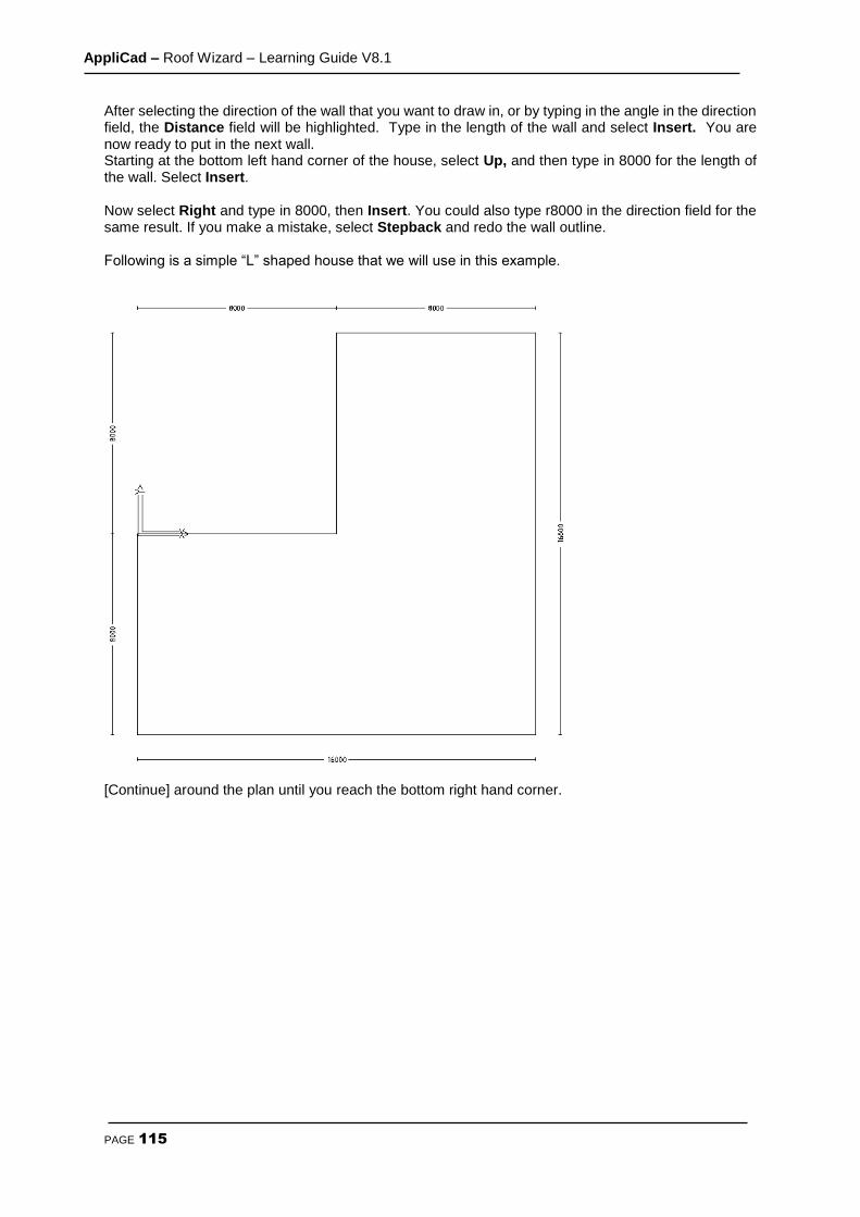
AppliCad – Roof Wizard – Learning Guide V8.1
PAGE 115
After selecting the direction of the wall that you want to draw in, or by typing in the angle in the direction field, the Distance field will be highlighted. Type in the length of the wall and select Insert. You are now ready to put in the next wall. Starting at the bottom left hand corner of the house, select Up, and then type in 8000 for the length of the wall. Select Insert.
Now select Right and type in 8000, then Insert. You could also type r8000 in the direction field for the same result. If you make a mistake, select Stepback and redo the wall outline.
Following is a simple “L” shaped house that we will use in this example.
[Continue] around the plan until you reach the bottom right hand corner.
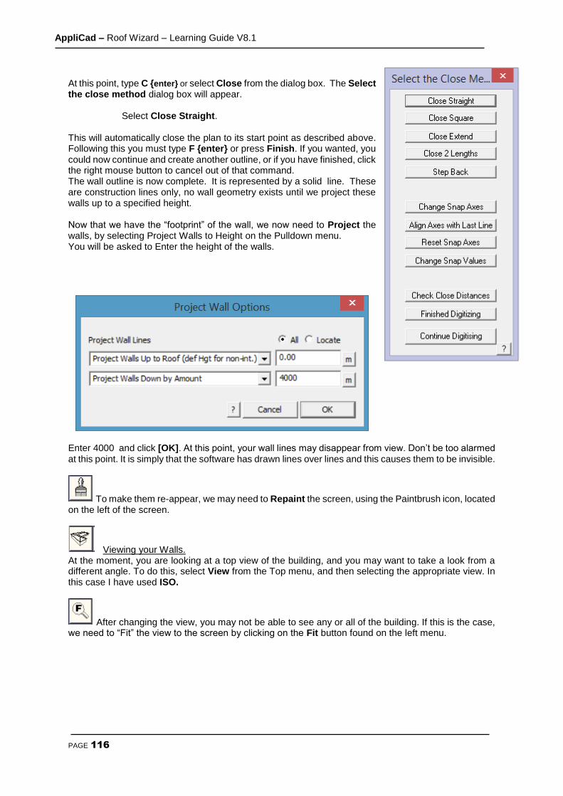
AppliCad – Roof Wizard – Learning Guide V8.1
PAGE 116
At this point, type C {enter} or select Close from the dialog box. The Select the close method dialog box will appear.
Select Close Straight.
This will automatically close the plan to its start point as described above. Following this you must type F {enter} or press Finish. If you wanted, you could now continue and create another outline, or if you have finished, click the right mouse button to cancel out of that command. The wall outline is now complete. It is represented by a solid line. These are construction lines only, no wall geometry exists until we project these walls up to a specified height. Now that we have the “footprint” of the wall, we now need to Project the walls, by selecting Project Walls to Height on the Pulldown menu. You will be asked to Enter the height of the walls.
Enter 4000 and click [OK]. At this point, your wall lines may disappear from view. Don’t be too alarmed at this point. It is simply that the software has drawn lines over lines and this causes them to be invisible.
To make them re-appear, we may need to Repaint the screen, using the Paintbrush icon, located on the left of the screen.
Viewing your Walls. At the moment, you are looking at a top view of the building, and you may want to take a look from a different angle. To do this, select View from the Top menu, and then selecting the appropriate view. In this case I have used ISO.
After changing the view, you may not be able to see any or all of the building. If this is the case, we need to “Fit” the view to the screen by clicking on the Fit button found on the left menu.

AppliCad – Roof Wizard – Learning Guide V8.1
PAGE 117
Your view should now look something like the one above. This completes the first exercise using Track-Outline. It is advisable that you save this job as you will need to re-open it later.
Exercise 2 - Track-Outline Now, for the practice, and using the process described above, do the following roof using the Walls-Track Outline command and using the dimensions shown.

AppliCad – Roof Wizard – Learning Guide V8.1
PAGE 118
Getting Wall Quantities To get geometric quantities, select Walls > Show Quantities. Select this and a dialog box is displayed with a summary of the geometric areas and lengths of the current wall. You must project your walls first! Notice you can export this information to a .csv format ascii file so that the information may be used in an external third party program such as Microsoft Excel.
Exercise 3 - Track-Outline Now that you have input these relatively simple wall designs, try the next one. Remember, if you make a mistake keying in the wall length, select Stepback and re-insert the correct value.
Start Here
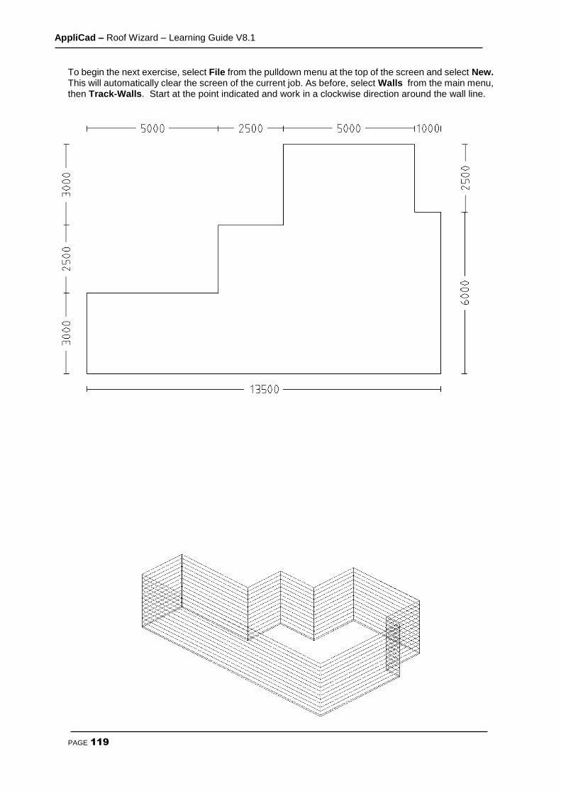
AppliCad – Roof Wizard – Learning Guide V8.1
PAGE 119
To begin the next exercise, select File from the pulldown menu at the top of the screen and select New. This will automatically clear the screen of the current job. As before, select Walls from the main menu, then Track-Walls. Start at the point indicated and work in a clockwise direction around the wall line.

AppliCad – Roof Wizard – Learning Guide V8.1
PAGE 120
To achieve this drawing, follow the outline above and project the walls to a hieght of 2700. Select View- ISO, and you should have a result like the one show.
Inserting Gable Ends If there are Vertical Planes on the building you must tell the software where they are. To do this select Walls > Gable. This will bring up the following dialog box.
Enter the pitch of the roof and then click [OK]. Select the end(s) that you want gable end(s) on by clicking on the top wall line, then right click the mouse button, and the siding for the Vertical Planes will be inserted. If you want the same material and orientation of panels as the base walls for your gable ends, you must select the command Walls > Merge-Gable and the wall and gable plane will be merged as one plane.
Select File – Save As, then save this as Training 2 with a model name of Job 2.
Using an Existing Wall Plan So far, we have explored the merits of “tracking” the wall outline using the Track-Walls command. However, there are times when you may have drawn up the building already whilst calculating a roof material take-off using one of our Roofing products. In this case, there is no need to re-enter the wall values again. If you recall from the previous learning guide, you go thru a similar process to enter the wall outline, prior to adding the roof, so we can now use that wall outline as if we had generated it using “Track-Walls”. In this example, I am going to use the following Outline as if we had generated it through the Construct-Roof/ Track-Outline command from the main menu (as described in detail earlier in this manual).
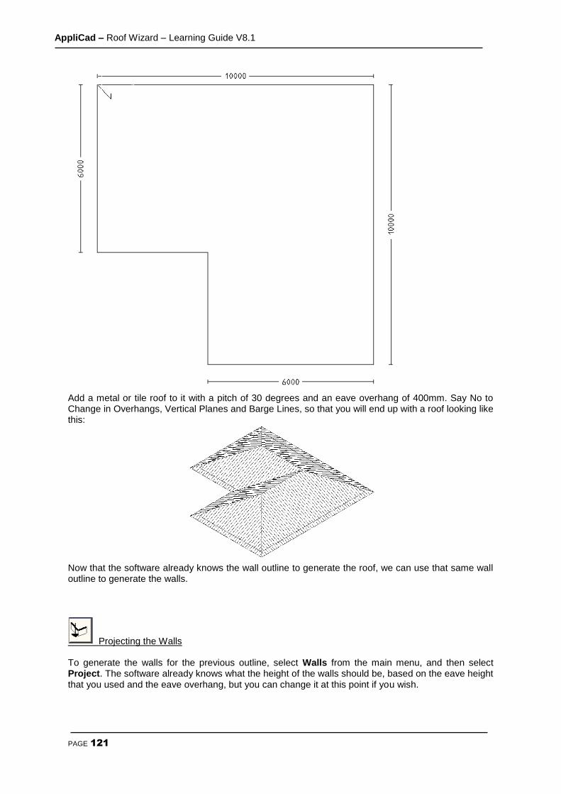
AppliCad – Roof Wizard – Learning Guide V8.1
PAGE 121
Add a metal or tile roof to it with a pitch of 30 degrees and an eave overhang of 400mm. Say No to Change in Overhangs, Vertical Planes and Barge Lines, so that you will end up with a roof looking like this:
Now that the software already knows the wall outline to generate the roof, we can use that same wall outline to generate the walls.
Projecting the Walls To generate the walls for the previous outline, select Walls from the main menu, and then select Project. The software already knows what the height of the walls should be, based on the eave height that you used and the eave overhang, but you can change it at this point if you wish.

AppliCad – Roof Wizard – Learning Guide V8.1
PAGE 122
After clicking [OK], you will notice that the walls are generated automatically. And you will end up with a view like this;
Finally, as there may be too much information appearing on the screen, we may want to “turn-off” the roof temporarily, so that we can concentrate on the walls. You do this by selecting Tools from the pulldown menu then Set Display. You can now select which part of the view you wish to turn off.
Note: Remember to turn them back on when you have finished!
Set to No

AppliCad – Roof Wizard – Learning Guide V8.1
PAGE 123
Using the Track-Edge Command There may be times when the edge of the wall has an extension or cut into it for some other feature. This can be achieved by using the Track-Edge command. In this example, I want you to open up L Shaped roof from exercise 1. You should have the following drawing on your screen.
Now select Track-Wall-Edge and you will be prompted which method to use to re-create the wall edge.
Select the desired option (in this example use Re-Track … by Track-Outline) then the wall line at the point (Point A) indicated on the previous page. You will then see the following box appear;
You will recognize this box from our Track-Outline or Track-Walls command. This time we will be entering the modification to the top line of the wall, using the Up/Down/Left/Right and Angle buttons. For this exercise, use these values – Firstly go Up 2000, then Right 2000, Then Down 1000, then Right 5000, then Up 2000, then Right 5000, then Down 1000, then Right 4000, then Down 2000. Now select
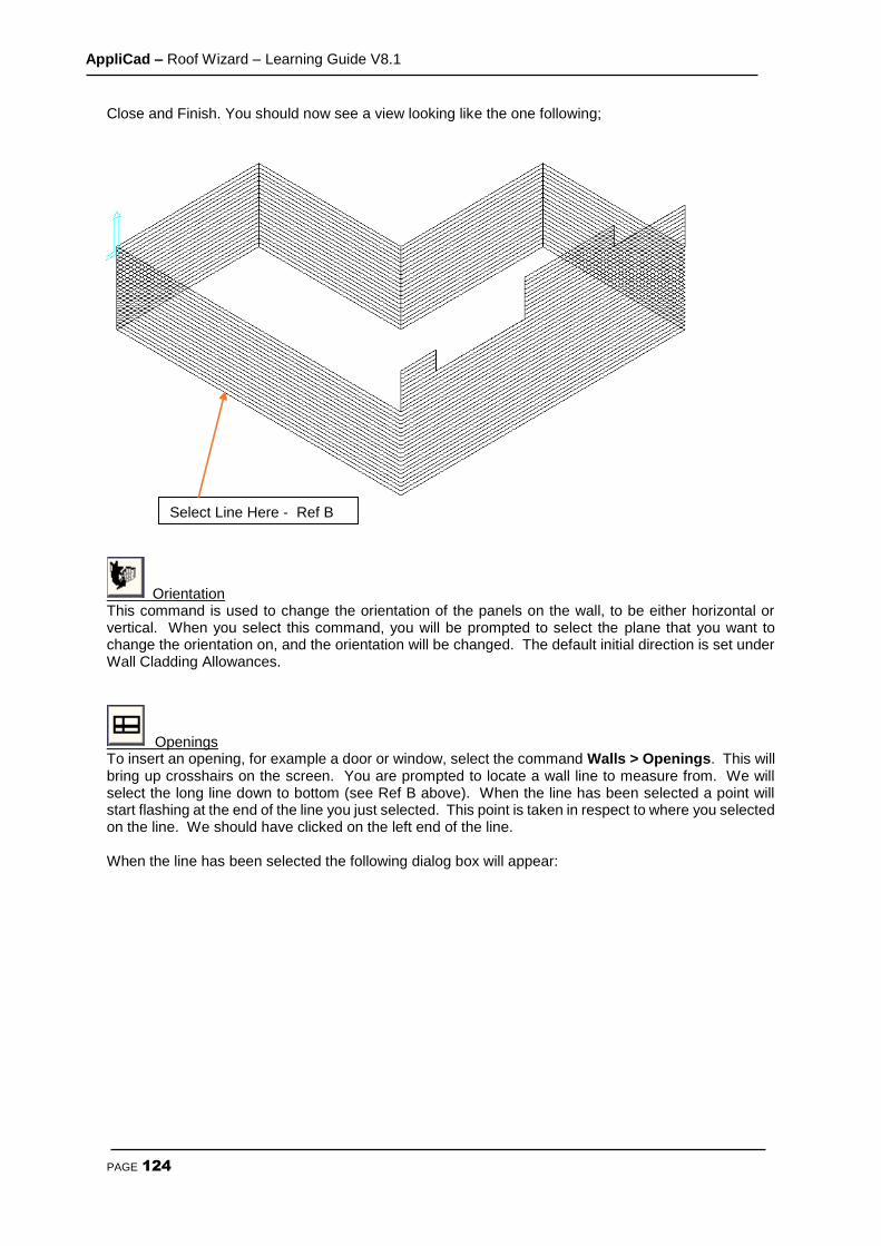
AppliCad – Roof Wizard – Learning Guide V8.1
PAGE 124
Close and Finish. You should now see a view looking like the one following;
Orientation This command is used to change the orientation of the panels on the wall, to be either horizontal or vertical. When you select this command, you will be prompted to select the plane that you want to change the orientation on, and the orientation will be changed. The default initial direction is set under Wall Cladding Allowances.
Openings To insert an opening, for example a door or window, select the command Walls > Openings. This will bring up crosshairs on the screen. You are prompted to locate a wall line to measure from. We will select the long line down to bottom (see Ref B above). When the line has been selected a point will start flashing at the end of the line you just selected. This point is taken in respect to where you selected on the line. We should have clicked on the left end of the line. When the line has been selected the following dialog box will appear:
Select Line Here - Ref B
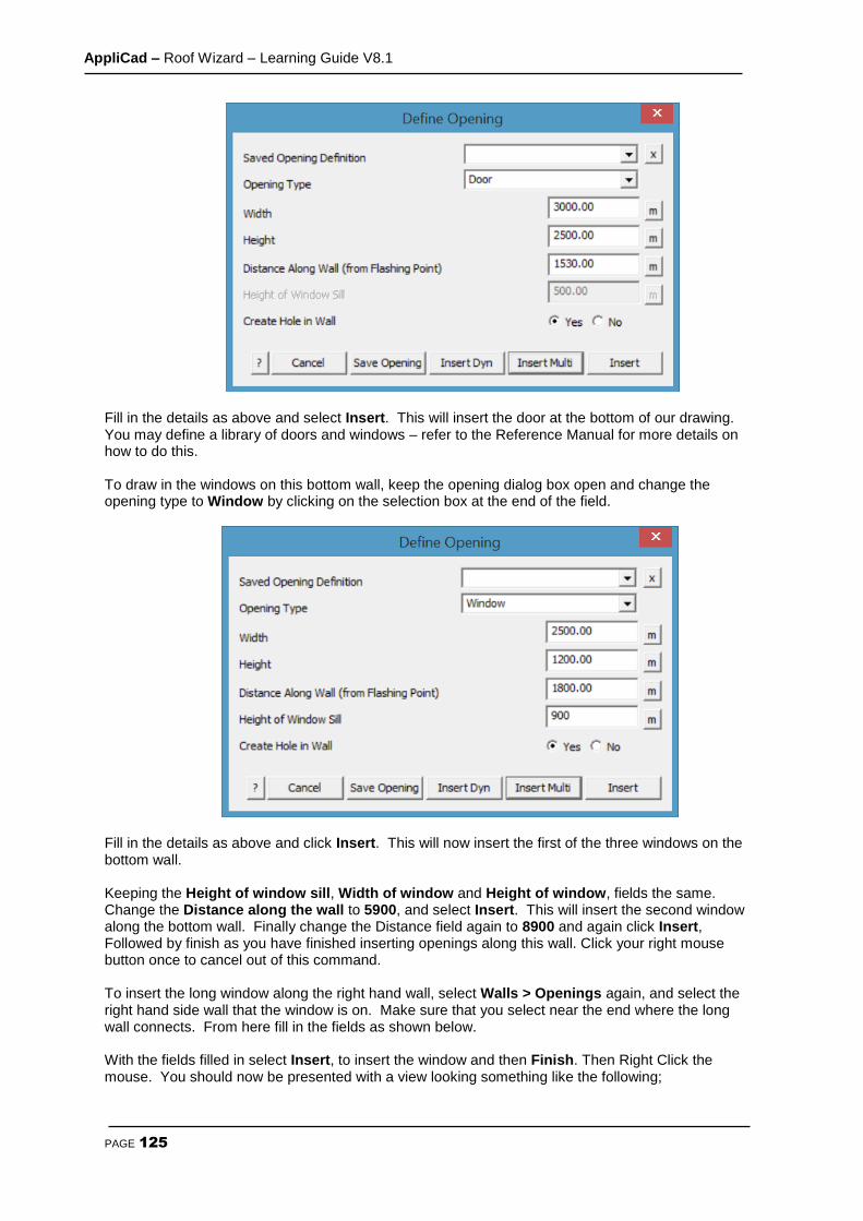
AppliCad – Roof Wizard – Learning Guide V8.1
PAGE 125
Fill in the details as above and select Insert. This will insert the door at the bottom of our drawing. You may define a library of doors and windows – refer to the Reference Manual for more details on how to do this. To draw in the windows on this bottom wall, keep the opening dialog box open and change the opening type to Window by clicking on the selection box at the end of the field.
Fill in the details as above and click Insert. This will now insert the first of the three windows on the bottom wall. Keeping the Height of window sill, Width of window and Height of window, fields the same. Change the Distance along the wall to 5900, and select Insert. This will insert the second window along the bottom wall. Finally change the Distance field again to 8900 and again click Insert, Followed by finish as you have finished inserting openings along this wall. Click your right mouse button once to cancel out of this command. To insert the long window along the right hand wall, select Walls > Openings again, and select the right hand side wall that the window is on. Make sure that you select near the end where the long wall connects. From here fill in the fields as shown below. With the fields filled in select Insert, to insert the window and then Finish. Then Right Click the mouse. You should now be presented with a view looking something like the following;
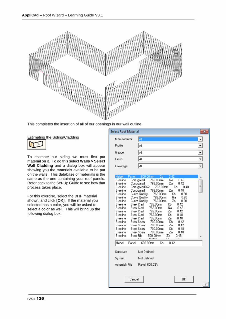
AppliCad – Roof Wizard – Learning Guide V8.1
PAGE 126
This completes the insertion of all of our openings in our wall outline.
Estimating the Siding/Cladding
To estimate our siding we must first put material on it. To do this select Walls > Select Wall Cladding and a dialog box will appear showing you the materials available to be put on the walls. This database of materials is the same as the one containing your roof panels. Refer back to the Set-Up Guide to see how that process takes place.
For this exercise, select the BHP material shown, and click [OK]. If the material you selected has a color, you will be asked to select a color as well. This will bring up the following dialog box.
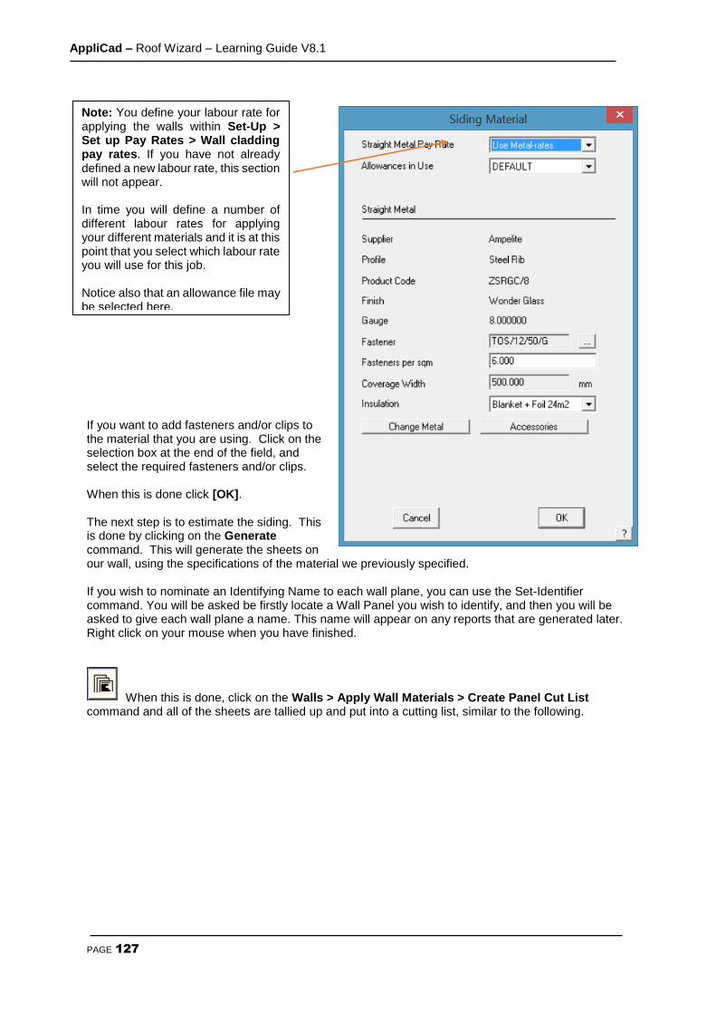
AppliCad – Roof Wizard – Learning Guide V8.1
PAGE 127
If you want to add fasteners and/or clips to the material that you are using. Click on the selection box at the end of the field, and select the required fasteners and/or clips. When this is done click [OK]. The next step is to estimate the siding. This is done by clicking on the Generate command. This will generate the sheets on our wall, using the specifications of the material we previously specified. If you wish to nominate an Identifying Name to each wall plane, you can use the Set-Identifier command. You will be asked be firstly locate a Wall Panel you wish to identify, and then you will be asked to give each wall plane a name. This name will appear on any reports that are generated later. Right click on your mouse when you have finished.
When this is done, click on the Walls > Apply Wall Materials > Create Panel Cut List command and all of the sheets are tallied up and put into a cutting list, similar to the following.
Note: You define your labour rate for applying the walls within Set-Up > Set up Pay Rates > Wall cladding pay rates. If you have not already defined a new labour rate, this section will not appear. In time you will define a number of different labour rates for applying your different materials and it is at this point that you select which labour rate you will use for this job. Notice also that an allowance file may be selected here.
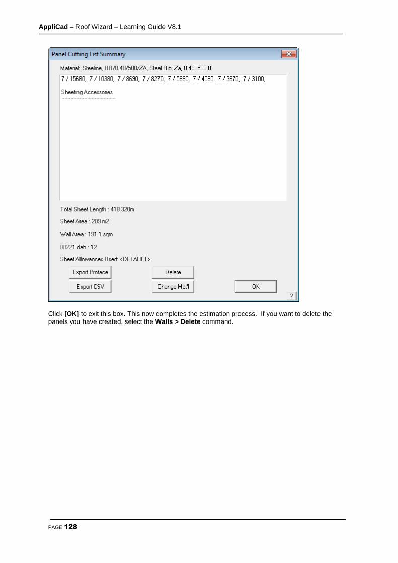
AppliCad – Roof Wizard – Learning Guide V8.1
PAGE 128
Click [OK] to exit this box. This now completes the estimation process. If you want to delete the panels you have created, select the Walls > Delete command.
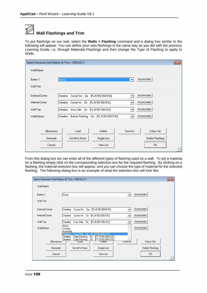
AppliCad – Roof Wizard – Learning Guide V8.1
PAGE 129
Wall Flashings and Trim To put flashings on our wall, select the Walls > Flashing command and a dialog box similar to the following will appear. You can define your own flashings in the same way as you did with the previous Learning Guide, i.e. through Materials-Flashings and then change the Type of Flashing to apply to Walls.
From this dialog box we can enter all of the different types of flashing used on a wall. To set a material for a flashing simply click on the corresponding selection box for the required flashing. By clicking on a flashing, the material selection box will appear, and you can choose the type of material for the selected flashing. The following dialog box is an example of what the selection box will look like.
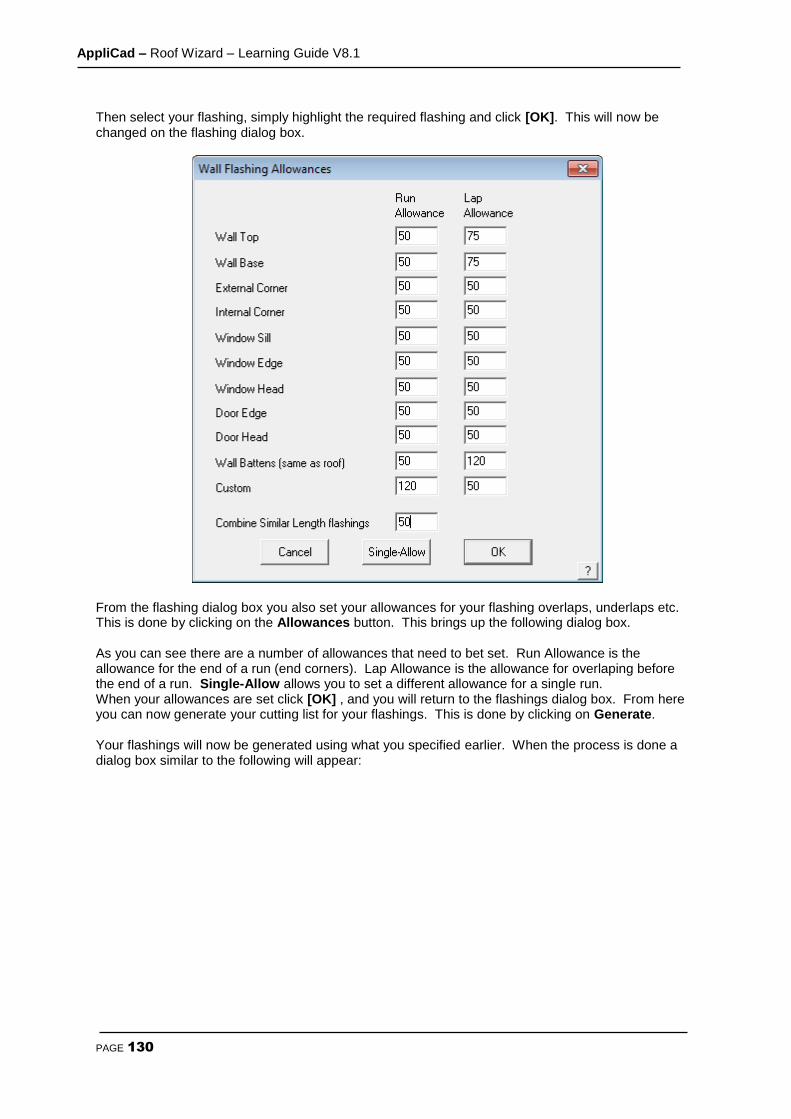
AppliCad – Roof Wizard – Learning Guide V8.1
PAGE 130
Then select your flashing, simply highlight the required flashing and click [OK]. This will now be changed on the flashing dialog box.
From the flashing dialog box you also set your allowances for your flashing overlaps, underlaps etc. This is done by clicking on the Allowances button. This brings up the following dialog box. As you can see there are a number of allowances that need to bet set. Run Allowance is the allowance for the end of a run (end corners). Lap Allowance is the allowance for overlaping before the end of a run. Single-Allow allows you to set a different allowance for a single run. When your allowances are set click [OK] , and you will return to the flashings dialog box. From here you can now generate your cutting list for your flashings. This is done by clicking on Generate. Your flashings will now be generated using what you specified earlier. When the process is done a dialog box similar to the following will appear:
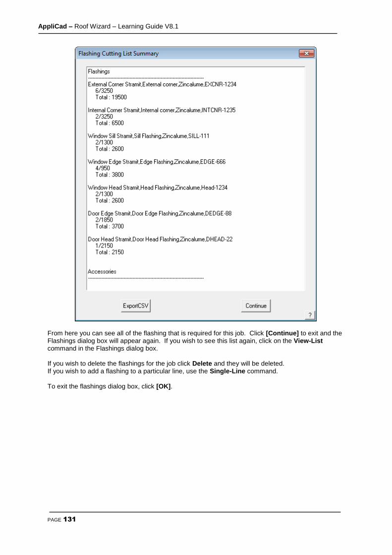
AppliCad – Roof Wizard – Learning Guide V8.1
PAGE 131
From here you can see all of the flashing that is required for this job. Click [Continue] to exit and the Flashings dialog box will appear again. If you wish to see this list again, click on the View-List command in the Flashings dialog box. If you wish to delete the flashings for the job click Delete and they will be deleted. If you wish to add a flashing to a particular line, use the Single-Line command. To exit the flashings dialog box, click [OK].

AppliCad – Roof Wizard – Learning Guide V8.1
PAGE 132
Reporting/Costing The costing command is where the cost of the materials and labour is calculated. Click on Reporting > Supply-Only or Supply-Install button – the same as you would have used in the Roof section, and the following dialog box will appear.
Fromt this dialog box you can see, all of the relavent information about pricing the job, quantity of material, price of material, etc. The labor component is taken from the Siding-Pay button (refer Page 19) , located in the Costing menu. Here you set a labor rate for each of the different features of the wall. You can modify the results by clicking on Labour Sub-Total and then hitting the Re-Calc button. From here you can print all of your quotation drawings by clicking on the Print button. You can also change some of the prices from this dialog box and save the quote using the Save button. The complete set of job pricing information is then saved into the model database and writes the name of the quote to a file saved in the \User folder called QuoteRegister.csv so that the job may be recalled by quote number from the File menu. At this point you can also print out elevation drawings for the walls by selecting Drawings from the main menu and then select either Wall Plan or Wall Elevation.

AppliCad – Roof Wizard – Learning Guide V8.1
PAGE 133
Section 2b – Learning Guide (English/Imperial Units)
About the Learning Guide The purpose of this section of the manual is to provide you a set of tutorials to work through with Roof Wizard. Some detailed advice has been provided but it should be read in conjunction with Section 5 of this Reference Guide, which describes the commands in more detail. We may refer to Roof Wizard but this also applies to the other packages shown above.
This guide has been divided up into 10 parts that takes you step by step through a typical job. These are;
1. The Interface
2. Modelling
3. Cover Tile
4. Cover Flashing
5. Cover Metal
6. Estimate Metal
7. Cover Built Up Roof
8. Layout Built Up Roof
9. Cover Downpipes, Underlay (Sarking), Insulation etc
10. Costing/Reporting There may be sections in this manual that don’t relate to you (ie. The section for metal roofs will not be of much interest if you are doing tile roofs). When you do come to one of these sections, simply skip it. All the information to help learn the AppliCad software for all material types has been included in this guide, so there may be surplus information if you are a specialist roofer.
The AppliCad Process The foundation of the AppliCad Roof Wizard software is based upon the creation of accurate roof geometry - ie the roof geometry must first be correctly modelled in 3D space. It is from this 3D definition of the roof that the roof areas and quantities are extracted. Clearly, if the roof modelling is not accurate, the whole process is compromised. To assist the operator in the roof modelling process, we have included some very sophisticated but simple, single mouse ‘click’ operations that allow a roof model to be built from basic principles.
The usual starting point for a roof using this system is an outline of the roof from which the hips and valleys are created. From this, just about any roof may be modelled by adding all the architectural features including dormers, atriums, gables, verandahs etc. After the roof geometry has been created, the roof cover material must be selected*.This is done by selecting the material to be used from a list of user defined materials be it tile, shingle slate or metal. The program automatically accounts for other associated and required fixtures, fittings and accessories. You may also select the type of flashings you want to use. After creating the material list, costing of the job is automatic, providing you with the ability to modify the quote prior to printing the necessary reports.
Roof Creation and Modification
The purpose of the following section is to familiarize you with the process of creating a roof in 3D from an Architectural drawing or site survey measurements.

AppliCad – Roof Wizard – Learning Guide V8.1
PAGE 134
Outline The modelling tutorials will be divided into two sections. The first is the creation of basic roof shapes using Construct-Roof including simple hip and gable roofs, flat and mono-pitch roofs, variable pitch gables and verandahs, as this is the ‘foundation’ of our estimating system. The second section will involve making modifications to the initial roof geometry using Modify Roof, adding Architectural features such as dutch gables, corner gables, atriums, cut-outs etc. This will be followed by tutorials on coverage and costing. Before We Start Before we start we make sure that your Preferences are set up correctly. This is set under the Set-Up > Preference Settings > System Preferences menu. This was outlined in Section 2. .
Exercise 1 - Track Outline For the first example, we will use a photocopy of a roof plan, just as you might get during the course of a day’s work. The dimensions shown refer to the wall outline and the eaves are offset from the walls by 1’6” and at the gable end the barge lines are offset from the wall by 1’. It is useful to ensure that the eave height is entered accurately as this will affect the relative location, lengths and areas of any other or future roof planes butting onto the existing roof. First select the Construct-Roof option from the Pulldown Menu at the top of the screen.
We will use Track Outline to input the wall outline as this will be the most usual method of outline definition. Select Construct Roof > Track Outline. Note: (If you had measurements of the eave outline instead of wall outline dimensions as we have here, you could enter those dimensions, but remember to change your eave offset and gable overhang to be zero.)
If a previous job has been started but interrupted for any reason, the Message box below appears so that you can work with the previous outline.
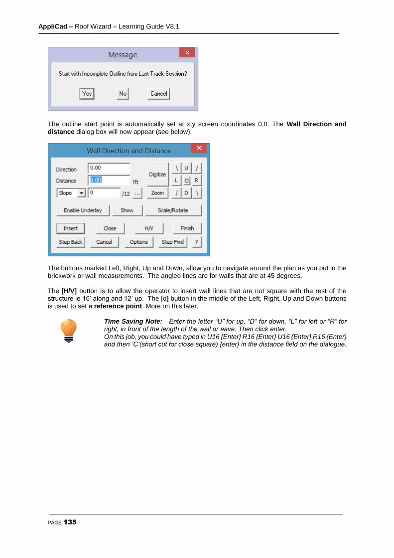
AppliCad – Roof Wizard – Learning Guide V8.1
PAGE 135
The outline start point is automatically set at x,y screen coordinates 0,0. The Wall Direction and distance dialog box will now appear (see below):
The buttons marked Left, Right, Up and Down, allow you to navigate around the plan as you put in the brickwork or wall measurements. The angled lines are for walls that are at 45 degrees. The [H/V] button is to allow the operator to insert wall lines that are not square with the rest of the structure ie 16’ along and 12’ up. The [o] button in the middle of the Left, Right, Up and Down buttons is used to set a reference point. More on this later.
Time Saving Note: Enter the letter “U” for up, “D” for down, “L” for left or “R” for right, in front of the length of the wall or eave. Then click enter. On this job, you could have typed in U16 {Enter} R16 {Enter} U16 {Enter} R16 {Enter} and then ‘C’(short cut for close square) {enter} in the distance field on the dialogue.
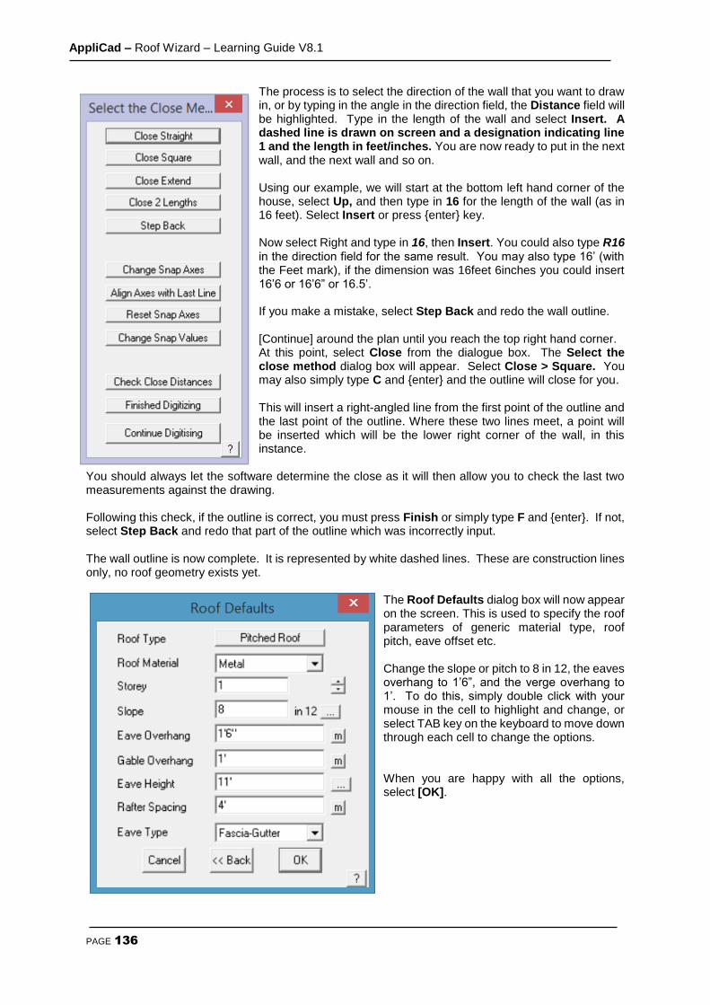
AppliCad – Roof Wizard – Learning Guide V8.1
PAGE 136
The process is to select the direction of the wall that you want to draw in, or by typing in the angle in the direction field, the Distance field will be highlighted. Type in the length of the wall and select Insert. A dashed line is drawn on screen and a designation indicating line 1 and the length in feet/inches. You are now ready to put in the next wall, and the next wall and so on. Using our example, we will start at the bottom left hand corner of the house, select Up, and then type in 16 for the length of the wall (as in 16 feet). Select Insert or press {enter} key. Now select Right and type in 16, then Insert. You could also type R16 in the direction field for the same result. You may also type 16’ (with the Feet mark), if the dimension was 16feet 6inches you could insert 16’6 or 16’6” or 16.5’. If you make a mistake, select Step Back and redo the wall outline. [Continue] around the plan until you reach the top right hand corner. At this point, select Close from the dialogue box. The Select the close method dialog box will appear. Select Close > Square. You may also simply type C and {enter} and the outline will close for you. This will insert a right-angled line from the first point of the outline and the last point of the outline. Where these two lines meet, a point will be inserted which will be the lower right corner of the wall, in this instance.
You should always let the software determine the close as it will then allow you to check the last two measurements against the drawing. Following this check, if the outline is correct, you must press Finish or simply type F and {enter}. If not, select Step Back and redo that part of the outline which was incorrectly input. The wall outline is now complete. It is represented by white dashed lines. These are construction lines only, no roof geometry exists yet.
The Roof Defaults dialog box will now appear on the screen. This is used to specify the roof parameters of generic material type, roof pitch, eave offset etc. Change the slope or pitch to 8 in 12, the eaves overhang to 1’6”, and the verge overhang to 1’. To do this, simply double click with your mouse in the cell to highlight and change, or select TAB key on the keyboard to move down through each cell to change the options. When you are happy with all the options, select [OK].

AppliCad – Roof Wizard – Learning Guide V8.1
PAGE 137
At this point, a dialog box will appear asking if you want to Define Vertical Planes, Change Eave-Verge Overhangs and Define Barge Line.
Click on Define Gable Ends. Using the left mouse button, select the left hand wall of the building outline (which is to have the gable end). You will notice in the prompt area (at the bottom of the screen), that it is still asking you to locate a wall. As there is only one gable on this building, press the right mouse button to cancel out of the selection process. A message box will now appear advising you of how many entities were located. You will then be asked if you want to use this entity. Select Yes. The above dialog box will appear again. If you wanted to change the eave or verge overhang for a wall, we would select that button, followed by the eave that we would like to change. In this instance, all of our eaves are at 1’, so we ignore it. We are also asked if we would like to Define Barge Lines. For this case we will ignore it as we will explain this command a little later. Now click [Continue]. The hip and valley roof is automatically created in 3D. Return to the Main menu by pressing the right mouse button.

AppliCad – Roof Wizard – Learning Guide V8.1
PAGE 138
If you wish to view the roof from another angle, you can change the view by selecting the View menu at top. Select the required view (in this case we’ll select Isometric View. Select Isometric View and then [OK]. This will enable us to look at the house in an isometric view. You may have to zoom fit the model by double clicking the centre mouse button to fit the entire model into the workspace. Note: If you change views and your roof seems to disappear, it is simply that you are zoomed into a small section of the drawing. You may need to zoom fit the appropriate view.
This completes the exercise using Track-Outline.
Save Your Job To save your job select File > Save from the Main menu. The following dialog box will be displayed.
AppliCad – Roof Wizard – Learning Guide V8.1
PAGE 139
Type in your project or customer name in space under File Name and the job name in the space under Model Name , then select [OK]. For this exercise, use File Name TRAINING and Model Name Exercise 1. You’re Done!
When you start work on real jobs, you will use your own job naming convention. You might for example use the name of the builder as the file name, and the site address as the model name. For example, MightyBuilders for the file name, and 27LongStreet as the model name.
Note: Do not use special keyboard characters in the file name – such as #,?,/,|,&, etc - in the names as it confuses software programs..
To begin the next exercise, select File from the pulldown menu at the top of the screen and select New. This will automatically clear the screen of the current job, or prompt you to save the current job if you haven’t already done so.
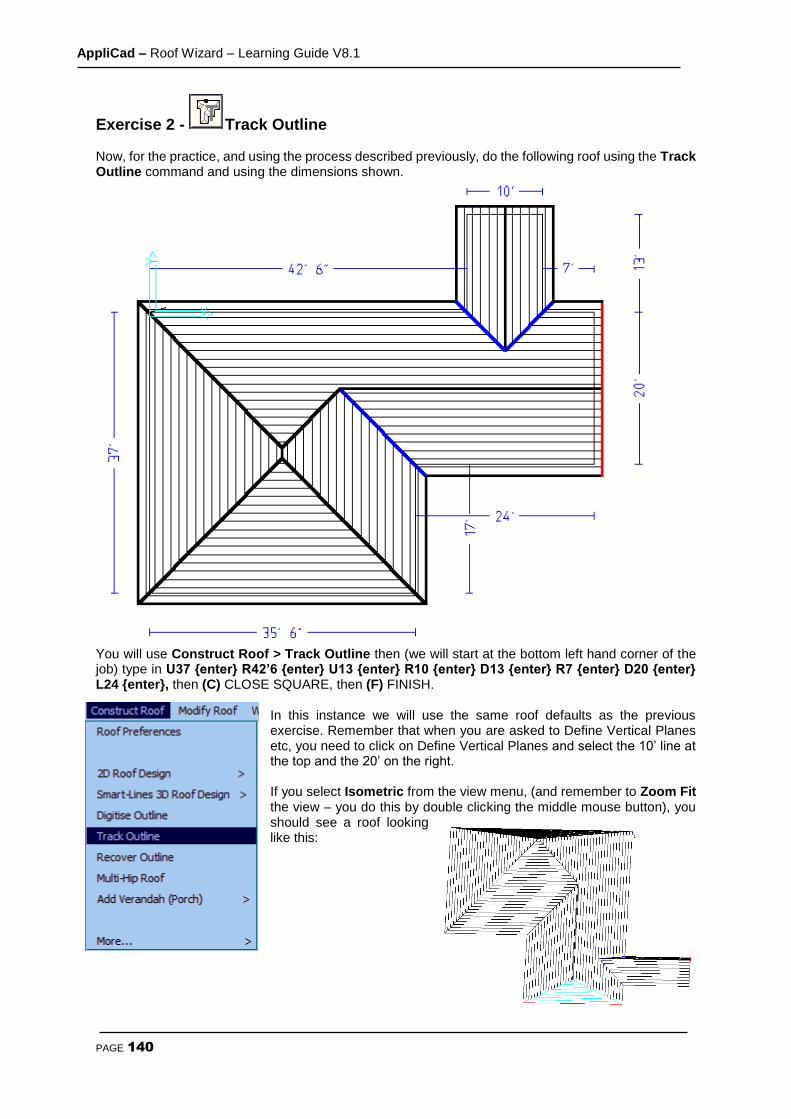
AppliCad – Roof Wizard – Learning Guide V8.1
PAGE 140
Exercise 2 - Track Outline Now, for the practice, and using the process described previously, do the following roof using the Track Outline command and using the dimensions shown.
You will use Construct Roof > Track Outline then (we will start at the bottom left hand corner of the job) type in U37 {enter} R42’6 {enter} U13 {enter} R10 {enter} D13 {enter} R7 {enter} D20 {enter} L24 {enter}, then (C) CLOSE SQUARE, then (F) FINISH.
In this instance we will use the same roof defaults as the previous exercise. Remember that when you are asked to Define Vertical Planes etc, you need to click on Define Vertical Planes and select the 10’ line at the top and the 20’ on the right. If you select Isometric from the view menu, (and remember to Zoom Fit the view – you do this by double clicking the middle mouse button), you should see a roof looking like this:

AppliCad – Roof Wizard – Learning Guide V8.1
PAGE 141
Something else you may want to do is to rotate the view to take a look at your roof model from a different angle. To rotate a roof in Isometric view, hold down the Ctrl key and the middle mouse button and move the cursor to position your model. You may also zoom in and out from your model using the middle mouse scroll wheel.
When you have finished, select File > Save As (from the top menu). You should see a file called Training.dab (which you created previously). Select this file on the left hand side and then type in Exercise 2 in the Model Name field. To begin the next exercise, select File from the pulldown menu at the top of the screen and select New. This will automatically clear the screen of the current job.
Exercise 3 - Track Outline – (using Angles) Now, using the commands already shown, try the roof outline below. An important thing to remember before you first begin to enter the values is to work out the best location of the Start Point based on what information you have been given. In this instance, there is one line which isn’t dimensioned (like that never happens on real drawings!) so we will use this line as our Closing Line, ie let the software calculate the length. We will be using the 45 degree direction button on the track outline dialogue this time. Another important thing to remember is that we cannot use Close Square on this job as the first and last lines are not at right angles to one another. We will use the Close Straight button this time. Leave the Roof Defaults as previously set.
Select a rotation point towards the front of the model (approx centre of floor plan)
Centre Point of Rotation is not at centre of
roof, but centre of floor plan.

AppliCad – Roof Wizard – Learning Guide V8.1
PAGE 142
Try it for yourself and compare the result to the drawing below for the way it should have worked out. You will achieve this by doing the following: Select Construct-Roof > Track Outline, then select the button 1 (see above) and enter a distance of 30’ {enter} then button 2 and enter a distance of 45 {enter}, then down 45 {enter}, then R30 {enter}, type C to Close and Press Enter. Then select Finish (or the short cut F {Enter}. Now stop! Stop for a moment or two and compare the wall dimensions displayed with what is on the plan. This is a way of checking that the outline compares with the job dimensions. When you have finished, select File > Save As. You should see a file called Training.dab (which you created previously) . Select this file on the left hand side and then type in Exercise 3 in the Model Name field.
Note: By now, you should be fairly comfortable with the basics of entering a roof or wall outline and generating a 3D roof from it. As you have seen, the software creates a hip and valley roof from the outline and assumes that the eave line is the same height. If you have a number of different eave heights for your roof, you may need to break the job down into separate components. This is covered with our Project Gable command section below.
To begin the next exercise, select File from the pulldown menu at the top of the screen and select New. This will automatically clear the screen of the current job. So far, we have dealt with the command Track Outline which automatically generates a Hip and Valley roof from the outline and the pitch. There may be times when you need to create a simple flat (or low slope) roof, or have a roof simply sloping up from one eave line, in the form of a flat plane. The following exercises will demonstrate how this is achieved. However, before we do this, let’s look at how we check that our job is correct.
All angles at 45 or 90 degrees
Start Here
1
2
Start Here
2
1

AppliCad – Roof Wizard – Learning Guide V8.1
PAGE 143
Checking your job – The AppliCad Process Before we proceed with the next exercise, we will use the Tools menu to check one of the previous jobs we have done. This is a most important step:
add dimensions - overall and up the slope,
add dimensions ridge to eave,
show roof pitch, check storey
show line types,
show four views, look at the picture
display total roof geometry (Tally Quantities)
This is a vital and integral part of the AppliCad Process and provides you with the tools to check the job before committing to materials and labour in your quotation.
From the Tools menu select Dimension > Auto-Insert Dimension to add overall eave to eave dimensions.
You may need to Zoom Fit the view to see all of the dimensions. Depending on the size of the roof, the dimensions may be too small to read.
If they are too small because of the scale of the job (that is it might be a huge job), this is adjusted by selecting View from the pulldown menu, followed by View > Plot Scale. A dialog box pops up and you are prompted to change the Plot Scale. Change the plot scale of the current job to say, 150, and select [OK]. The dimensions are redrawn at a more legible size.
Then select Tools > Dimension Roof > Roof Line Lengths to display the length of each line up the slope of the roof. Then select Tools > Show Pitches to display the roof storey and the roof pitch of each roof plane. This is a ‘toggle’ switch. This means that you select it to display and select it again to turn the annotation off. Then select Tools > Show Line Types to display the category of each line on the roof. There are occasions where you may decide to change the line type, but we will deal with this later. This is a ‘toggle’ switch. This means that you select it to display and select it again to turn the annotation off. Go to the pulldown menu and select View > Four Views to display four views of the roof model. The default setting is Top view, ISO view, Front View and Right View. You may have to zoom fit the screen (double-click centre mouse button) in each view to display the full extents of each view of the roof model. Finally, to get geometric quantities, select Tools > Tally-Quantities. Select this and a dialog box is displayed with a summary of the geometric areas and lengths of the current roof.

AppliCad – Roof Wizard – Learning Guide V8.1
PAGE 144
This function may also be accessed from the Icon Menu – >
Additional model Information including No. of Roof Planes, No. of Eave Heights, No. of Pitches, No. of Roof Holes and No. of Barge Lines to the Display Tally dialog when Show Full is selected.

AppliCad – Roof Wizard – Learning Guide V8.1
PAGE 145
Notice also that you can export this information to a .csv (Comma Separated Values) format ascii text file using the Export CSV as well as an XLS file format button, so that this basic roof geometry information may be used in other systems that may be using in your business with Microsoft Excel.
Important Note: The steps described above are imperative. Use them on every job without fail so that you check every aspect of the roof geometry BEFORE you determine material quantities. Better to find a problem now, than when you have delivered the job!
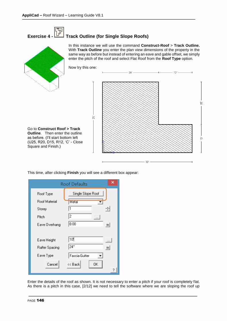
AppliCad – Roof Wizard – Learning Guide V8.1
PAGE 146
Exercise 4 - Track Outline (for Single Slope Roofs)
In this instance we will use the command Construct-Roof > Track Outline. With Track Outline you enter the plan view dimensions of the property in the same way as before but instead of entering an eave and gable offset, we simply enter the pitch of the roof and select Flat Roof from the Roof Type option. Now try this one:
Go to Construct Roof > Track Outline. Then enter the outline as before. (I’ll start bottom left (U25, R20, D15, R12, ‘C’ - Close Square and Finish.) This time, after clicking Finish you will see a different box appear:
Enter the details of the roof as shown. It is not necessary to enter a pitch if your roof is completely flat. As there is a pitch in this case, [2/12] we need to tell the software where we are sloping the roof up
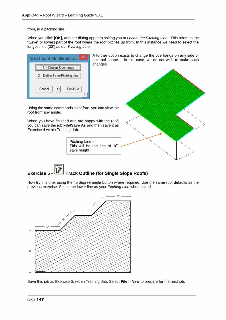
AppliCad – Roof Wizard – Learning Guide V8.1
PAGE 147
from, ie a pitching line. When you click [OK], another dialog appears asking you to Locate the Pitching Line This refers to the “Eave“ or lowest part of the roof where the roof pitches up from. In this instance we need to select the longest line (32’) as our Pitching Line.
A further option exists to change the overhangs on any side of our roof shape. In this case, we do not wish to make such changes.
Using the same commands as before, you can view the roof from any angle. When you have finished and are happy with the roof, you can save the job File/Save As and then save it as Exercise 4 within Training.dab.
Exercise 5 - Track Outline (for Single Slope Roofs) Now try this one, using the 45 degree angle button where required. Use the same roof defaults as the previous exercise. Select the lower line as your Pitching Line when asked.
Save this job as Exercise 5, within Training.dab. Select File > New to prepare for the next job.
Pitching Line – This will be the line at 10’ eave height
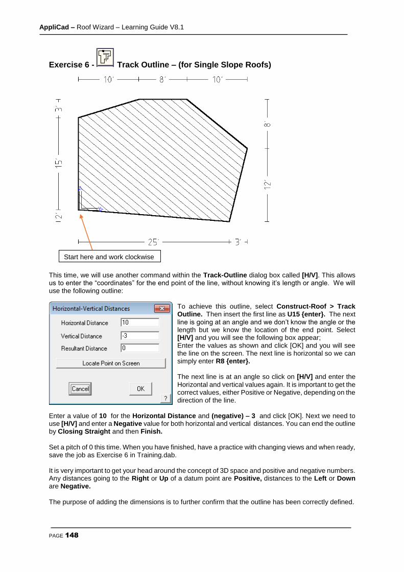
AppliCad – Roof Wizard – Learning Guide V8.1
PAGE 148
Exercise 6 - Track Outline – (for Single Slope Roofs)
This time, we will use another command within the Track-Outline dialog box called [H/V]. This allows us to enter the “coordinates” for the end point of the line, without knowing it’s length or angle. We will use the following outline:
To achieve this outline, select Construct-Roof > Track Outline. Then insert the first line as U15 {enter}. The next line is going at an angle and we don’t know the angle or the length but we know the location of the end point. Select [H/V] and you will see the following box appear; Enter the values as shown and click [OK] and you will see the line on the screen. The next line is horizontal so we can simply enter R8 {enter}. The next line is at an angle so click on [H/V] and enter the Horizontal and vertical values again. It is important to get the correct values, either Positive or Negative, depending on the direction of the line.
Enter a value of 10 for the Horizontal Distance and (negative) – 3 and click [OK]. Next we need to use [H/V] and enter a Negative value for both horizontal and vertical distances. You can end the outline by Closing Straight and then Finish. Set a pitch of 0 this time. When you have finished, have a practice with changing views and when ready, save the job as Exercise 6 in Training.dab. It is very important to get your head around the concept of 3D space and positive and negative numbers. Any distances going to the Right or Up of a datum point are Positive, distances to the Left or Down are Negative. The purpose of adding the dimensions is to further confirm that the outline has been correctly defined.
Start here and work clockwise
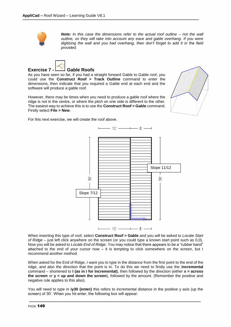
AppliCad – Roof Wizard – Learning Guide V8.1
PAGE 149
Note: In this case the dimensions refer to the actual roof outline – not the wall outline, so they will take into account any eave and gable overhang. If you were digitising the wall and you had overhang, then don’t forget to add it in the field provided.
Exercise 7 - Gable Roofs As you have seen so far, if you had a straight forward Gable to Gable roof, you could use the Construct Roof > Track Outline command to enter the dimensions, then indicate that you required a Gable end at each end and the software will produce a gable roof. However, there may be times when you need to produce a gable roof where the ridge is not in the centre, or where the pitch on one side is different to the other. The easiest way to achieve this is to use the Construct Roof > Gable command. Firstly select File > New. For this next exercise, we will create the roof above. When inserting this type of roof, select Construct Roof > Gable and you will be asked to Locate Start of Ridge – just left click anywhere on the screen (or you could type a known start point such as 0,0). Now you will be asked to Locate End of Ridge. You may notice that there appears to be a “rubber band” attached to the end of your cursor now – it is tempting to click somewhere on the screen, but I recommend another method. When asked for the End of Ridge, I want you to type in the distance from the first point to the end of the ridge, and also the direction that the point is in. To do this we need to firstly use the incremental command – shortened to I (as in I for Incremental), then followed by the direction (either x = across the screen or y = up and down the screen), followed by the amount. (Remember the positive and negative rule applies to this also). You will need to type in iy30 {enter} this refers to incremental distance in the positive y axis (up the screen) of 30’. When you hit enter, the following box will appear:
Slope 11/12
Slope 7/12
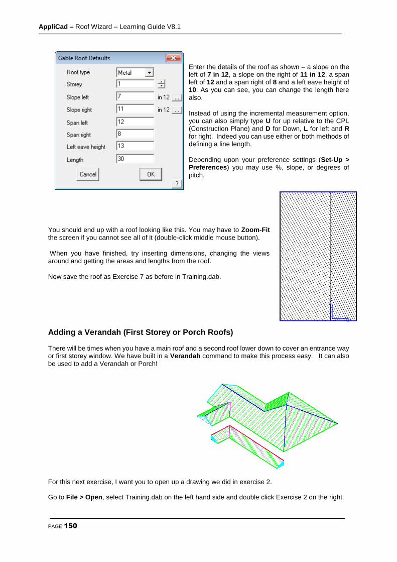
AppliCad – Roof Wizard – Learning Guide V8.1
PAGE 150
Enter the details of the roof as shown – a slope on the left of 7 in 12, a slope on the right of 11 in 12, a span left of 12 and a span right of 8 and a left eave height of 10. As you can see, you can change the length here also.
Instead of using the incremental measurement option, you can also simply type U for up relative to the CPL (Construction Plane) and D for Down, L for left and R for right. Indeed you can use either or both methods of defining a line length.
Depending upon your preference settings (Set-Up > Preferences) you may use %, slope, or degrees of pitch.
You should end up with a roof looking like this. You may have to Zoom-Fit the screen if you cannot see all of it (double-click middle mouse button).
When you have finished, try inserting dimensions, changing the views around and getting the areas and lengths from the roof.
Now save the roof as Exercise 7 as before in Training.dab.
Adding a Verandah (First Storey or Porch Roofs) There will be times when you have a main roof and a second roof lower down to cover an entrance way or first storey window. We have built in a Verandah command to make this process easy. It can also be used to add a Verandah or Porch!
For this next exercise, I want you to open up a drawing we did in exercise 2. Go to File > Open, select Training.dab on the left hand side and double click Exercise 2 on the right.

AppliCad – Roof Wizard – Learning Guide V8.1
PAGE 151
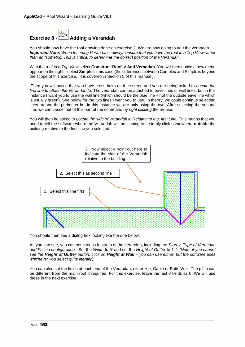
AppliCad – Roof Wizard – Learning Guide V8.1
PAGE 152
Exercise 8 - Adding a Verandah You should now have the roof drawing done on exercise 2. We are now going to add the verandah. Important Note: When Inserting Verandahs, always ensure that you have the roof in a Top View rather than an Isometric. This is critical to determine the correct position of the Verandah. With the roof in a Top View select Construct-Roof > Add Verandah. You will then notice a new menu appear on the right – select Simple in this case (the differences between Complex and Simple is beyond the scope of this exercise. It is covered in Section 5 of this manual ). Then you will notice that you have cross-hairs on the screen and you are being asked to Locate the first line to attach the Verandah to. The verandah can be attached to eave lines or wall lines, but in this instance I want you to use the wall line (which should be the blue line – not the outside eave line which is usually green). See below for the two lines I want you to use. In theory, we could continue selecting lines around the perimeter but in this instance we are only using the two. After selecting the second line, we can cancel out of this part of the command by right clicking the mouse. You will then be asked to Locate the side of Verandah in Relation to the first Line. This means that you need to tell the software where the Verandah will be sloping to – simply click somewhere outside the building relative to the first line you selected.
You should then see a dialog box looking like the one below: As you can see, you can set various features of the verandah, including the Storey, Type of Verandah and Fascia configuration. Set the Width to 5’ and set the Height of Gutter to 11’. (Note: if you cannot see the Height of Gutter button, click on Height at Wall – you can use either, but the software uses whichever you select quite literally). You can also set the finish at each end of the Verandah, either Hip, Gable or Butts Wall. The pitch can be different from the main roof if required. For this exercise, leave the last 3 fields as 0. We will use these in the next exercise.
1. Select this line first
2. Select this as second line
3. Now select a point out here to indicate the side of the Verandah relative to the building.

AppliCad – Roof Wizard – Learning Guide V8.1
PAGE 153
It is useful to verify what the verandah may look like before inserting it - click Preview and you will see the verandah displayed on the screen. If you need to refine any measurements, make the change and preview again. Things to check in the preview are the start and end preparation, as selecting the correct treatment ensures that the right material will be applied when you get to that stage. If they are not correct, change the setting and select preview again.
Note: If the dialog box obscures the view of the roof, move your cursor to the blue strip at the top of the box and, whilst holding down the left mouse button, drag the dialog box to a more suitable location on the screen.
If the Verandah looks correct, click [OK] and you should see this:
As you know, you can change the view to make sure that it has gone in at the correct height. If you make a mistake with any Roof Modelling functions such as inserting the Verandah, you can use the Undo and Redo commands on the Icon Menu to step back to the previous command. Try it for yourself. Now that we have made some changes, you might want to save it as a new name. Select File >Save
AppliCad – Roof Wizard – Learning Guide V8.1
PAGE 154
as and then save it as Exercise 8 within Training.dab

AppliCad – Roof Wizard – Learning Guide V8.1
PAGE 155
Exercise 9 - Adding a Verandah II For this exercise, we will open up the roof we created in Exercise 1. The end result will look like this:
In the previous exercise, you will have noticed that the verandah was built along the full length of each wall that we selected. There will be many instances where the verandah is only part of the way along a wall. For this function we need specify the Distance from First Point and Distance from Last Point (It is indicated on the screen which are the first and last points) After making sure that your roof is in a top view, select Construct Roof > Add Verandah and select the two wall lines (blue lines) where the verandah is attached. Then right click the mouse and when asked for the side of the verandah, left click somewhere outside the building, in relation to the first line you selected.
This time, when entering the information about the verandah, change the Start Preparation to Hip and set the Distance from first point to 8’ and Last Point to 15’. Preview the roof and then click [OK] when happy. Change the views to check the height is correct.
Note: A common mistake when inserting Verandahs is to insert at the wrong height. If your verandah looks wrong, UNDO and repeat the process, ensuring that you have set the correct Height of Gutter or Height at Wall button on the dialog box.
Save this job as Exercise 9 in Training.dab.
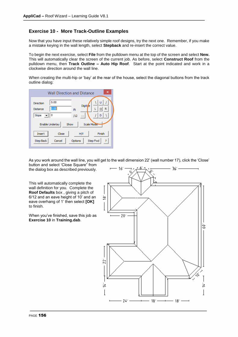
AppliCad – Roof Wizard – Learning Guide V8.1
PAGE 156
Exercise 10 - More Track-Outline Examples Now that you have input these relatively simple roof designs, try the next one. Remember, if you make a mistake keying in the wall length, select Stepback and re-insert the correct value. To begin the next exercise, select File from the pulldown menu at the top of the screen and select New. This will automatically clear the screen of the current job. As before, select Construct Roof from the pulldown menu, then Track Outline – Auto Hip Roof. Start at the point indicated and work in a clockwise direction around the wall line. When creating the multi-hip or ‘bay’ at the rear of the house, select the diagonal buttons from the track outline dialog:
As you work around the wall line, you will get to the wall dimension 22’ (wall number 17), click the ‘Close’ button and select ‘Close Square” from the dialog box as described previously. This will automatically complete the wall definition for you. Complete the Roof Defaults box , giving a pitch of 6/12 and an eave height of 10’ and an eave overhang of 1’ then select [OK] to finish. When you’ve finished, save this job as Exercise 10 in Training.dab.
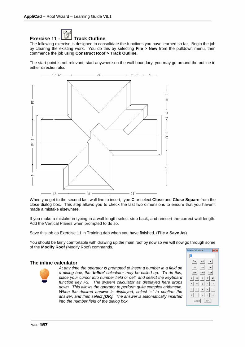
AppliCad – Roof Wizard – Learning Guide V8.1
PAGE 157
Exercise 11 - Track Outline The following exercise is designed to consolidate the functions you have learned so far. Begin the job by clearing the existing work. You do this by selecting File > New from the pulldown menu, then commence the job using Construct Roof > Track Outline. The start point is not relevant, start anywhere on the wall boundary, you may go around the outline in either direction also.
When you get to the second last wall line to insert, type C or select Close and Close-Square from the close dialog box. This step allows you to check the last two dimensions to ensure that you haven’t made a mistake elsewhere. If you make a mistake in typing in a wall length select step back, and reinsert the correct wall length. Add the Vertical Planes when prompted to do so. Save this job as Exercise 11 in Training.dab when you have finished. (File > Save As) You should be fairly comfortable with drawing up the main roof by now so we will now go through some of the Modify Roof (Modify Roof) commands.
The inline calculator
At any time the operator is prompted to insert a number in a field on a dialog box, the ‘Inline’ calculator may be called up. To do this, place your cursor into number field or cell, and select the keyboard function key F3. The system calculator as displayed here drops down. This allows the operator to perform quite complex arithmetic. When the desired answer is displayed, select ‘=’ to confirm the answer, and then select [OK]. The answer is automatically inserted into the number field of the dialog box.
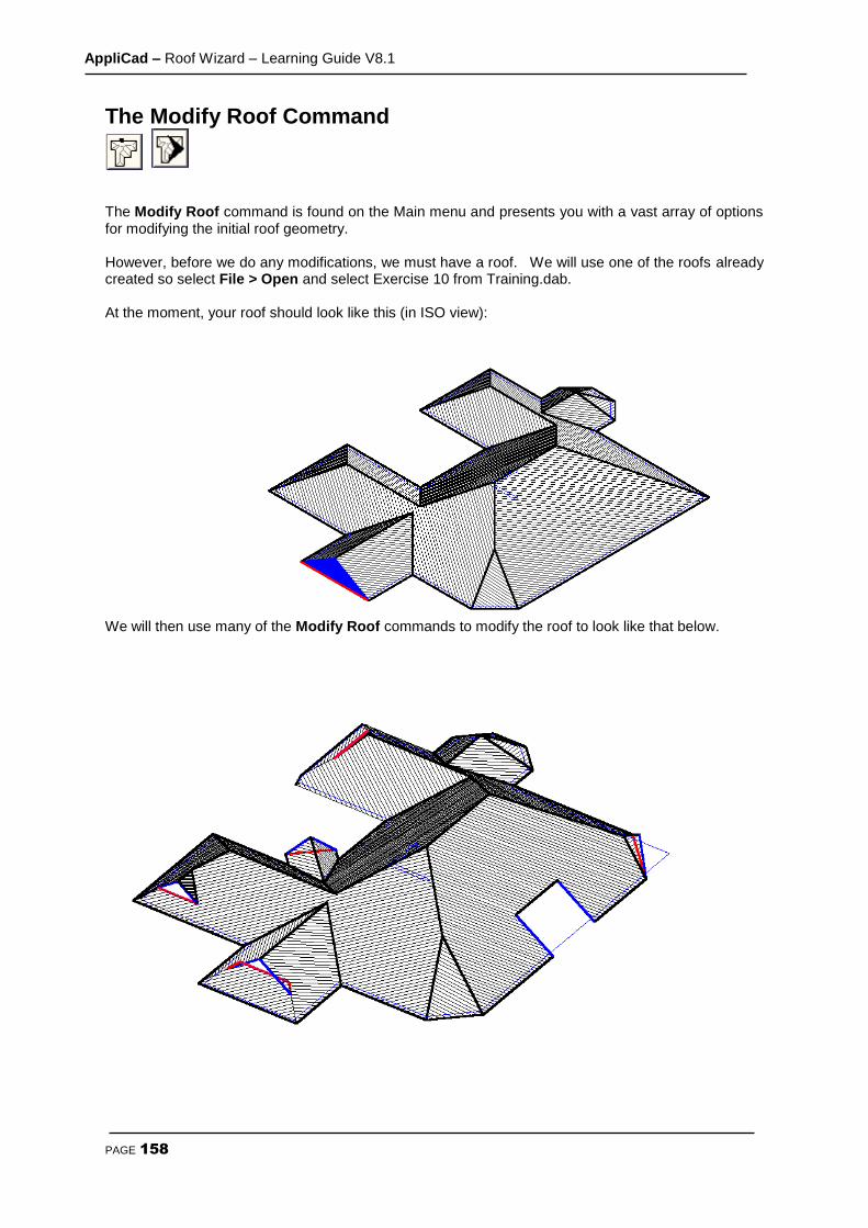
AppliCad – Roof Wizard – Learning Guide V8.1
PAGE 158
The Modify Roof Command
The Modify Roof command is found on the Main menu and presents you with a vast array of options for modifying the initial roof geometry. However, before we do any modifications, we must have a roof. We will use one of the roofs already created so select File > Open and select Exercise 10 from Training.dab. At the moment, your roof should look like this (in ISO view):
We will then use many of the Modify Roof commands to modify the roof to look like that below.
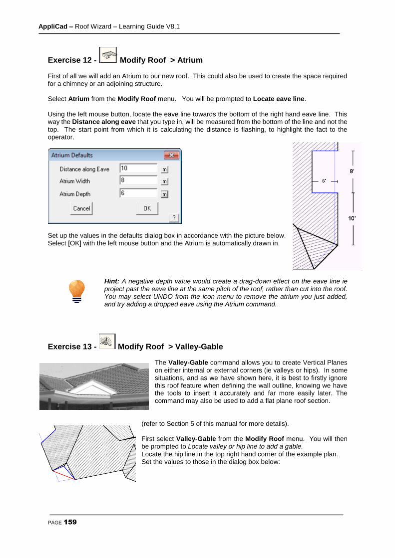
AppliCad – Roof Wizard – Learning Guide V8.1
PAGE 159
Exercise 12 - Modify Roof > Atrium First of all we will add an Atrium to our new roof. This could also be used to create the space required for a chimney or an adjoining structure. Select Atrium from the Modify Roof menu. You will be prompted to Locate eave line. Using the left mouse button, locate the eave line towards the bottom of the right hand eave line. This way the Distance along eave that you type in, will be measured from the bottom of the line and not the top. The start point from which it is calculating the distance is flashing, to highlight the fact to the operator.
Set up the values in the defaults dialog box in accordance with the picture below. Select [OK] with the left mouse button and the Atrium is automatically drawn in.
Hint: A negative depth value would create a drag-down effect on the eave line ie project past the eave line at the same pitch of the roof, rather than cut into the roof. You may select UNDO from the icon menu to remove the atrium you just added, and try adding a dropped eave using the Atrium command.
Exercise 13 - Modify Roof > Valley-Gable
The Valley-Gable command allows you to create Vertical Planes on either internal or external corners (ie valleys or hips). In some situations, and as we have shown here, it is best to firstly ignore this roof feature when defining the wall outline, knowing we have the tools to insert it accurately and far more easily later. The command may also be used to add a flat plane roof section.
(refer to Section 5 of this manual for more details). First select Valley-Gable from the Modify Roof menu. You will then be prompted to Locate valley or hip line to add a gable. Locate the hip line in the top right hand corner of the example plan. Set the values to those in the dialog box below:

AppliCad – Roof Wizard – Learning Guide V8.1
PAGE 160
Click [OK] when you’re happy with the numbers and the gable is created. We will now do the corner gable in the courtyard area of the plan ie. on the valley line. The procedure is the same as a corner gable on a hip, except in this case, we will be putting in a value of 4’ for the extension and a roof pitch of 7/12. The distance along the fascia in this case will be 8’.
This function has a further option which becomes evident when you select the Gable button. The options expand to include a function for adding a flat plane along the valley to a known pitch or to the apex of the ridge and valley. This option is dealt with further in the Learning Guide.

AppliCad – Roof Wizard – Learning Guide V8.1
PAGE 161
Exercise 14 - Modify Roof > Gable To Hip Select Gable To Hip from the Modify Roof menu. Locate the ridge line of the gable at the front of the house at the eave end.
A dialog box will appear asking you to enter the new pitch. We want it to be the same pitch as the rest of the roof, so accept the default of 7/12. This value was automatically extracted by the system from the pitch used for the whole roof. (You can change this pitch if required) It has now been converted to a hip.
Exercise 15 - Modify Roof > Dutch Gable On that same part of the roof as in Exercise 13, we now need to create a Dutch Gable. Select Dutch Gable from the Modify Roof menu. You will be prompted to Locate ridge at hip end. (the eave line will now flash) to indicate that the measurement of the base of hip is from the eave line.

AppliCad – Roof Wizard – Learning Guide V8.1
PAGE 162

AppliCad – Roof Wizard – Learning Guide V8.1
PAGE 163
Useful Tip: When you select a line or point and you may see a box appear asking you ‘Enter Y to use this entity’. It means that the software has found a number of points or lines in the vicinity of where you selected, and is asking you to confirm if the feature flashing on the screen is the correct one.
You can select the options on this dialog box by using the mouse button short cuts: yes – no – cancel maybe selected by left – middle – right on a three button mouse without selecting the buttons on the dialog. Try this, it saves time when you get used to it!
Exercise 16 - Modify Roof > Flying Gable Select Flying Gable from the Modify Roof menu. You will be prompted to Locate eave line followed by the hip.
The dialog box below will appear. Set the values in the dialog box to:
Note: If we had typed in zero for the Distance of gable apex from top of hip, instead of 5, the flying gable would have started at the intersection of the ridge and hip.
For flying gables that sit flush with the eave line, type in zero in the Distance of gable from eave field.

AppliCad – Roof Wizard – Learning Guide V8.1
PAGE 164
Exercise 17 - Modify Roof > Lay Back Gable (or Gambrel)
Select Lay Back from the Modify Roof menu. You will be prompted to Locate ridge at hip end. The dialog
box below will appear. Set the values in the dialog box to:
Note: This command may also be used to add a layback gable on a gable end as well as a hip.
Exercise 18 - Modify Roof > Slice Hip Select Slice Hip from the Modify Roof menu. You will be prompted to Locate eave. The dialog box below will appear. Set the value in the dialog box to:
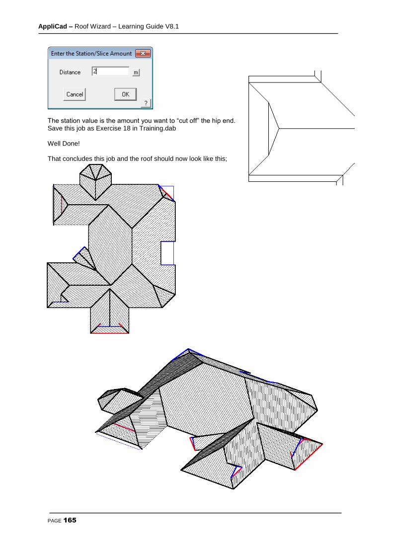
AppliCad – Roof Wizard – Learning Guide V8.1
PAGE 165
The station value is the amount you want to “cut off” the hip end. Save this job as Exercise 18 in Training.dab Well Done! That concludes this job and the roof should now look like this;
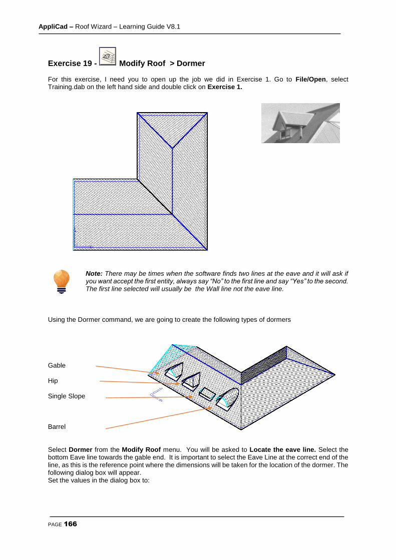
AppliCad – Roof Wizard – Learning Guide V8.1
PAGE 166
Exercise 19 - Modify Roof > Dormer For this exercise, I need you to open up the job we did in Exercise 1. Go to File/Open, select Training.dab on the left hand side and double click on Exercise 1.
Note: There may be times when the software finds two lines at the eave and it will ask if you want accept the first entity, always say “No” to the first line and say “Yes” to the second. The first line selected will usually be the Wall line not the eave line.
Using the Dormer command, we are going to create the following types of dormers Gable Hip Single Slope Barrel Select Dormer from the Modify Roof menu. You will be asked to Locate the eave line. Select the bottom Eave line towards the gable end. It is important to select the Eave Line at the correct end of the line, as this is the reference point where the dimensions will be taken for the location of the dormer. The following dialog box will appear. Set the values in the dialog box to:
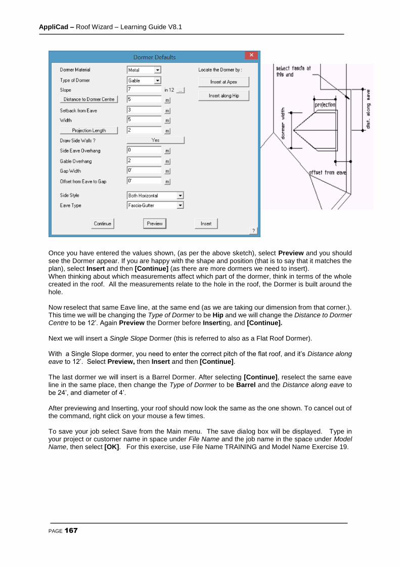
AppliCad – Roof Wizard – Learning Guide V8.1
PAGE 167
Once you have entered the values shown, (as per the above sketch), select Preview and you should see the Dormer appear. If you are happy with the shape and position (that is to say that it matches the plan), select Insert and then [Continue] (as there are more dormers we need to insert). When thinking about which measurements affect which part of the dormer, think in terms of the whole created in the roof. All the measurements relate to the hole in the roof, the Dormer is built around the hole. Now reselect that same Eave line, at the same end (as we are taking our dimension from that corner.). This time we will be changing the Type of Dormer to be Hip and we will change the Distance to Dormer Centre to be 12’. Again Preview the Dormer before Inserting, and [Continue]. Next we will insert a Single Slope Dormer (this is referred to also as a Flat Roof Dormer). With a Single Slope dormer, you need to enter the correct pitch of the flat roof, and it’s Distance along eave to 12’. Select Preview, then Insert and then [Continue]. The last dormer we will insert is a Barrel Dormer. After selecting [Continue], reselect the same eave line in the same place, then change the Type of Dormer to be Barrel and the Distance along eave to be 24’, and diameter of 4’. After previewing and Inserting, your roof should now look the same as the one shown. To cancel out of the command, right click on your mouse a few times. To save your job select Save from the Main menu. The save dialog box will be displayed. Type in your project or customer name in space under File Name and the job name in the space under Model Name, then select [OK]. For this exercise, use File Name TRAINING and Model Name Exercise 19.

AppliCad – Roof Wizard – Learning Guide V8.1
PAGE 168
Exercise 20 - Modify Roof > Split Gable
Before we explore the Split Gable command, we need to have a simple gable roof on screen first. Select File > New and then select Construct Roof > Track AutoRoof and enter the following wall dimensions;
Using the values shown on the left, create your roof and remember to select the left and right wall lines when asked if you want any Gable Ends. After you have created the gable roof, select the Modify Roof menu, then Split-Gable. You will be prompted to Locate ridge at gable end. Locate the ridge at the end closest to the left of the screen. The end of ridge you select determines at which end the Split-Gable is inserted on the roof. The dialog box will appear. Set the values to those shown below: You should end up with the drawing below.

AppliCad – Roof Wizard – Learning Guide V8.1
PAGE 169
So that you can go back to this exercise, you should save it. To save your job select Save from the Main menu. The save dialog box will be displayed. Type in your project or customer name in space under File Name and the job name in the space under Model Name, then select [OK]. For this exercise, use File Name TRAINING and Model Name Exercise 20
Exercise 21 - Modify Roof > Project Gable Using the roof from the previous exercise, we will draw a line indicating a boundary line. To draw the boundary line, select Modify Roof from the Main menu, then select Advanced, Ins-Line, then Free. With the left mouse button, digitise two points on screen where you want the boundary line to appear. For the purposes of this exercise, digitise your boundary line anywhere approximately as shown below. Then double click the right mouse button to cancel the line insert function as you have finished inserting the line. Select Project Gable from the Modify Roof menu.
Boundary Line

AppliCad – Roof Wizard – Learning Guide V8.1
PAGE 170
You will then be prompted to Locate ridge at gable end. Locate the ridge line of the “split-gable” roof at the boundary line end. You will then be prompted to Select Plane Specification. The text menu on the right hand side of the screen will now have changed to list a number of “Plane Type” options. Select Line, and using the left mouse button, select the boundary line. The gable end is extended to meet the boundary line and automatically trimmed to be aligned with the boundary line.
The second picture is an example of projecting a gable into another roof plane. To achieve this, you would draw up the main roof first, using Construct Roof > Track Outline then draw up the second roof, detached from the main roof. Then by using the Modify Roof > Project Gable command, we select the ridge of the new, smaller roof (at the end nearest the main roof), then select that we wish to project onto a Plane (instead of a line), and then enter a Tuck Under value. This is the distance that the eave of the new roof is tucking under the eave of the existing roof.
Tuck-under

AppliCad – Roof Wizard – Learning Guide V8.1
PAGE 171
Exercise 22 - Review of Track Outline The purpose of this exercise is to combine some of the commands you have used in the previous sections, thus consolidating your learning. Using Construct Roof then Track Outline, create the following roof outline.
Note: You will notice that there is a bay window on the plan, which is slightly different from the one you did previously. This one has a hip and a valley coming from where the angled wall of the bay meets the wall of the house. The software will automatically put in a valley only when it comes across an internal corner, so to force it to construct a valley, we have to make a small adjustment when inserting the walls. If you look carefully, you will see a very short length of wall between the bay and the main wall of the house. The length of this wall is calculated by multiplying the eave overhang by 0.6. In this case, the eave overhang is 3’, therefore using the above calculation - 3’ x 0.6, the length of this wall is 1’ 9.6”. (When this exercise is complete, perhaps insert the outline without adding the short segment and see the difference in the resultant roof shape.) Also be aware that we add the valley gable end on the hip, lower right side, and the extended eave on the northern-most wall AFTER the rest of the roof has been created using the Track Outline function. If you forgot to do this, you must re-insert the correct outline. Select Modify Roof then Valley Gable to add the gable on the hip end, and select Mod Roof then Atrium to add the extended eave - remembering to use a negative value for the offset so that it extends out from the eave line instead of into the roof line. Save the job as Exercise 22.
Start Here
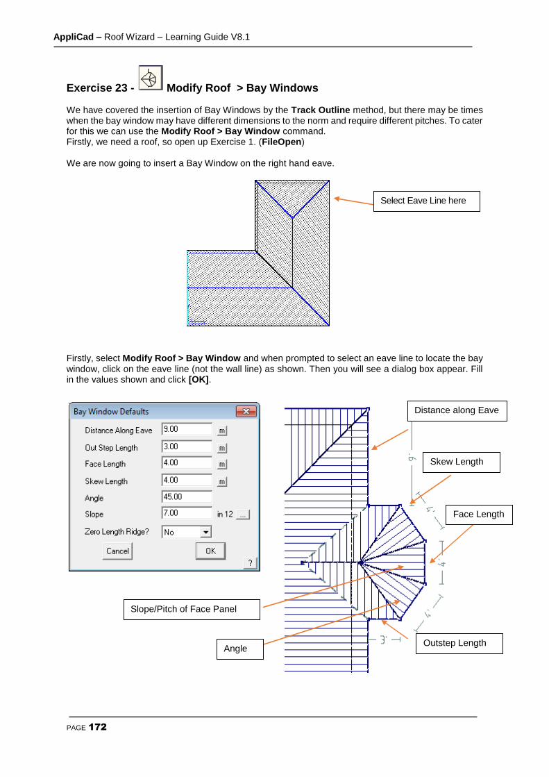
AppliCad – Roof Wizard – Learning Guide V8.1
PAGE 172
Exercise 23 - Modify Roof > Bay Windows We have covered the insertion of Bay Windows by the Track Outline method, but there may be times when the bay window may have different dimensions to the norm and require different pitches. To cater for this we can use the Modify Roof > Bay Window command. Firstly, we need a roof, so open up Exercise 1. (FileOpen) We are now going to insert a Bay Window on the right hand eave.
Firstly, select Modify Roof > Bay Window and when prompted to select an eave line to locate the bay window, click on the eave line (not the wall line) as shown. Then you will see a dialog box appear. Fill in the values shown and click [OK].
Select Eave Line here
Outstep Length Angle
Slope/Pitch of Face Panel
Distance along Eave
Skew Length
Face Length
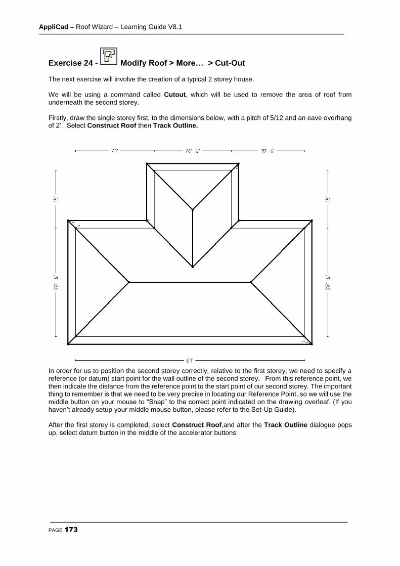
AppliCad – Roof Wizard – Learning Guide V8.1
PAGE 173
Exercise 24 - Modify Roof > More… > Cut-Out The next exercise will involve the creation of a typical 2 storey house. We will be using a command called Cutout, which will be used to remove the area of roof from underneath the second storey. Firstly, draw the single storey first, to the dimensions below, with a pitch of 5/12 and an eave overhang of 2’. Select Construct Roof then Track Outline.
In order for us to position the second storey correctly, relative to the first storey, we need to specify a reference (or datum) start point for the wall outline of the second storey. From this reference point, we then indicate the distance from the reference point to the start point of our second storey. The important thing to remember is that we need to be very precise in locating our Reference Point, so we will use the middle button on your mouse to “Snap” to the correct point indicated on the drawing overleaf. (If you haven’t already setup your middle mouse button, please refer to the Set-Up Guide). After the first storey is completed, select Construct Roof,and after the Track Outline dialogue pops up, select datum button in the middle of the accelerator buttons
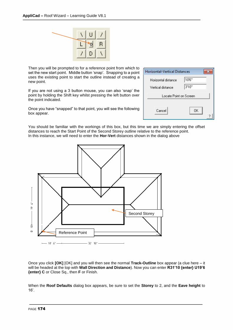
AppliCad – Roof Wizard – Learning Guide V8.1
PAGE 174
Then you will be prompted to for a reference point from which to set the new start point. Middle button ‘snap’. Snapping to a point uses the existing point to start the outline instead of creating a new point. If you are not using a 3 button mouse, you can also ‘snap’ the point by holding the Shift key whilst pressing the left button over the point indicated. Once you have “snapped” to that point, you will see the following box appear. You should be familiar with the workings of this box, but this time we are simply entering the offset distances to reach the Start Point of the Second Storey outline relative to the reference point. In this instance, we will need to enter the Hor-Vert distances shown in the dialog above
Once you click [OK] [OK] and you will then see the normal Track-Outline box appear (a clue here – it will be headed at the top with Wall Direction and Distance). Now you can enter R31’10 {enter} U19’6 {enter} C or Close Sq., then F or Finish. When the Roof Defaults dialog box appears, be sure to set the Storey to 2, and the Eave height to 16’.
Reference Point
Second Storey
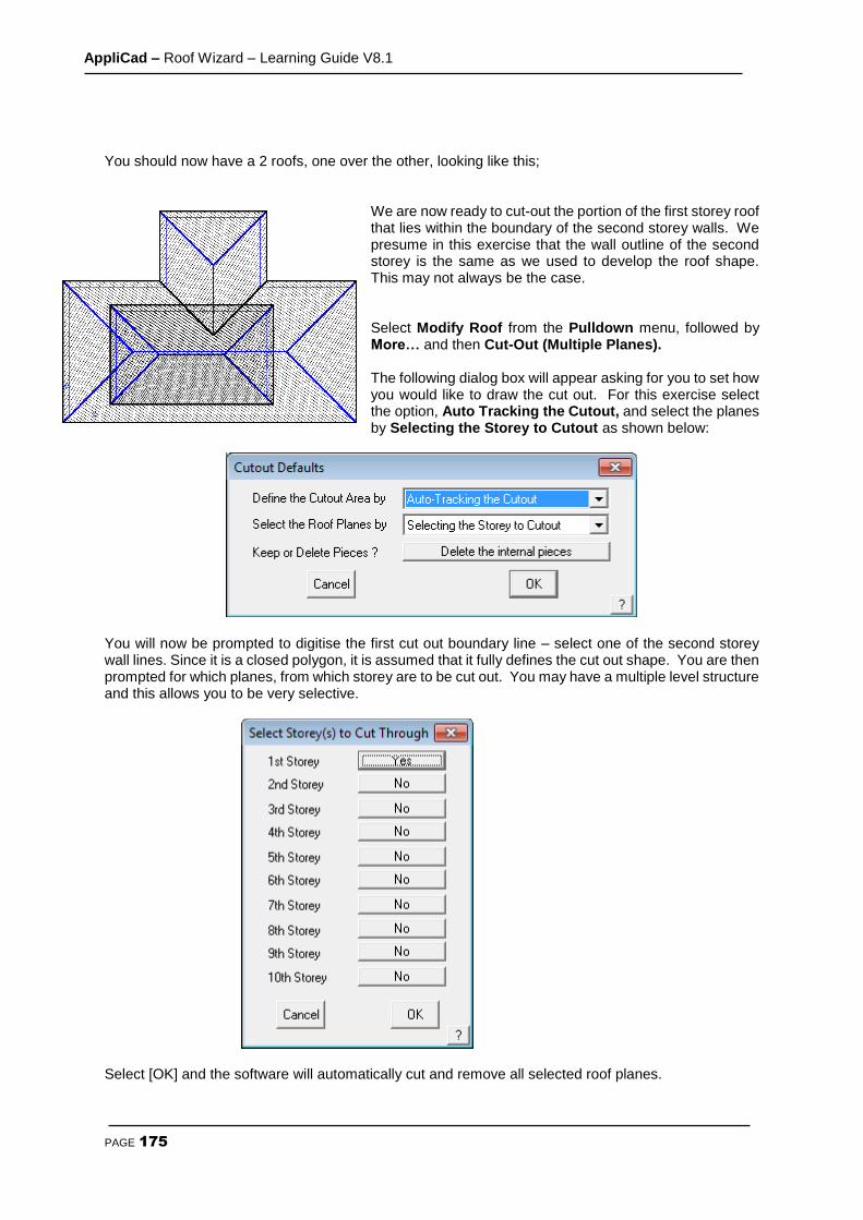
AppliCad – Roof Wizard – Learning Guide V8.1
PAGE 175
You should now have a 2 roofs, one over the other, looking like this;
We are now ready to cut-out the portion of the first storey roof that lies within the boundary of the second storey walls. We presume in this exercise that the wall outline of the second storey is the same as we used to develop the roof shape. This may not always be the case. Select Modify Roof from the Pulldown menu, followed by More… and then Cut-Out (Multiple Planes). The following dialog box will appear asking for you to set how you would like to draw the cut out. For this exercise select the option, Auto Tracking the Cutout, and select the planes by Selecting the Storey to Cutout as shown below:
You will now be prompted to digitise the first cut out boundary line – select one of the second storey wall lines. Since it is a closed polygon, it is assumed that it fully defines the cut out shape. You are then prompted for which planes, from which storey are to be cut out. You may have a multiple level structure and this allows you to be very selective.
Select [OK] and the software will automatically cut and remove all selected roof planes.
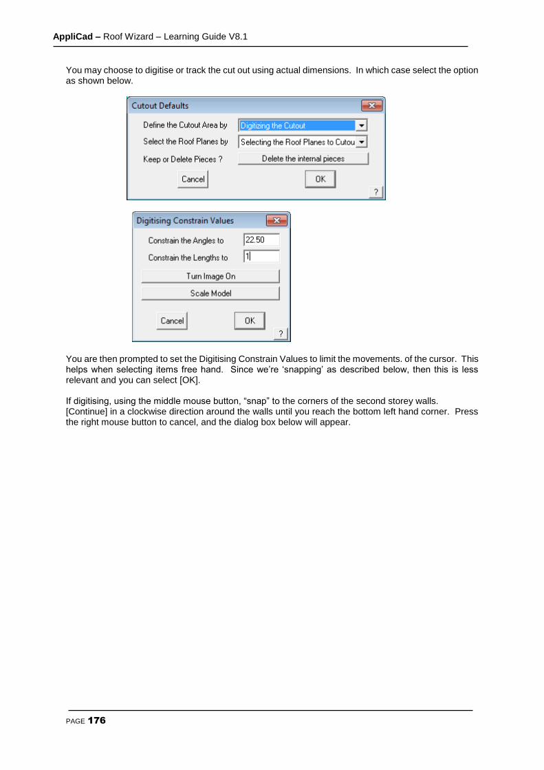
AppliCad – Roof Wizard – Learning Guide V8.1
PAGE 176
You may choose to digitise or track the cut out using actual dimensions. In which case select the option as shown below.
You are then prompted to set the Digitising Constrain Values to limit the movements. of the cursor. This helps when selecting items free hand. Since we’re ‘snapping’ as described below, then this is less relevant and you can select [OK]. If digitising, using the middle mouse button, “snap” to the corners of the second storey walls. [Continue] in a clockwise direction around the walls until you reach the bottom left hand corner. Press the right mouse button to cancel, and the dialog box below will appear.

AppliCad – Roof Wizard – Learning Guide V8.1
PAGE 177
Note: You may also type U/D/R/L and an exact measurement in the required direction and use C to close the outline square while in this command.
Select Close Square (as described earlier in Tutorial one) Next you will see the Instruction to select the roof planes to cut-out.
Using your mouse, you will need to select all of the roof planes that you wish to be affected by the cut-out. In this instance it will be most of the first storey roof planes.
The first storey roof within the selected boundary will now be automatically removed.
These are the roof planes that will be affected by the walls of the second storey. Select each of these. They will change colour after you have selected them. When you have finished selecting the planes, right click your mouse once and you will be asked if you want to use these entities. Say Yes.

AppliCad – Roof Wizard – Learning Guide V8.1
PAGE 178
Your job should look like this when viewed in ISO view: (Main View Select ISO).

AppliCad – Roof Wizard – Learning Guide V8.1
PAGE 179
Exercise 25 - Modify Roof > More… > Cut-Out The next exercise will also involve a 2 storey house, however in this case, the lower storey will be “cut in” to the second storey. We will still be using the Cutout command, but applying it in a slightly different way. Draw the second storey first, to the dimensions overleaf, with an eave overhang of 2’ and an eave height of 32’. Next, draw the lower storey at a height of 12’, using Construct Roof > Track Outline. Use the method described above to establish the start point for the second storey as before. Then enter the values shown below. Now, when you see the Enter Wall Direction and Distance box, enter L18’ {enter} D21’ {enter} Close Square, Finish.
You should get a series of roofs looking like this:

AppliCad – Roof Wizard – Learning Guide V8.1
PAGE 180
Now proceed to remove the portion of the lower storey roof that intrudes into the upper storey area. Using Modify Roof > More…> Cut-Out, use the same settings as the previous example;
When you click [OK], select the Wall Lines of the larger roof, and then select the first storey as the storey to cut. When viewed in ISO, your plan should look like the one below.
This completes the tutorials for generating roof geometry. Now we must deal with the estimating and take-off aspects of the task. Please review the work you have completed, and when comfortable, progress to the next stage.

AppliCad – Roof Wizard – Learning Guide V8.1
PAGE 181
Cover Command For Flashings
Exercise 26 - Generating the Flashing cutting list. This exercise deals with generating flashings or trim for the roof. If you don’t quote on flashings and trim, you can skip this section. Select Cover > Flashings and the Roof flashing material dialog box will appear, listing all of the roof trim components to be specified. Only those categories of roof trim on the model will be listed in the dialog box. (We will skip battens/purlins for now, they are dealt with in the next exercise.)
Starting at the top of the Roof Trim section, select the drop down arrow Ridge. After selecting Ridge, the list of available choices for the ridge capping is displayed.
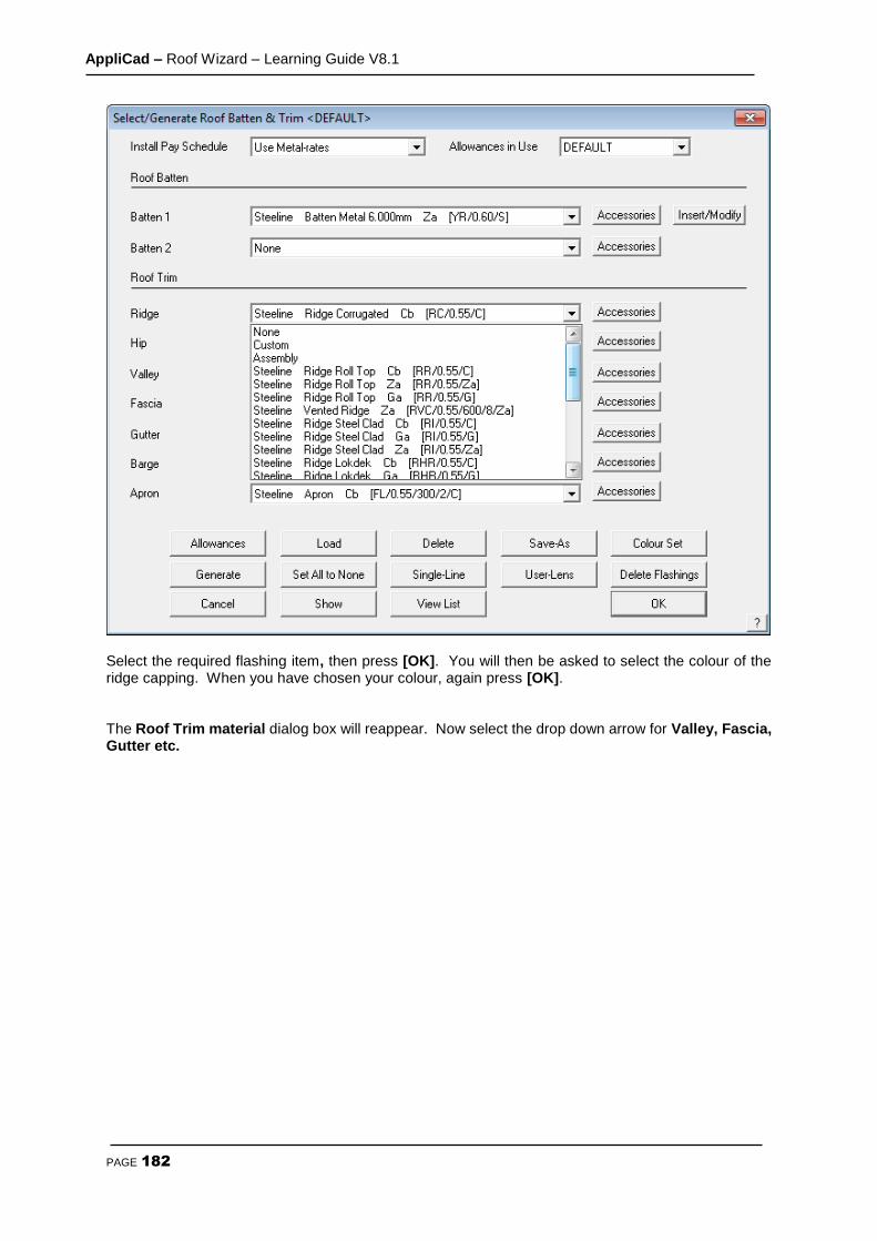
AppliCad – Roof Wizard – Learning Guide V8.1
PAGE 182
Select the required flashing item, then press [OK]. You will then be asked to select the colour of the ridge capping. When you have chosen your colour, again press [OK]. The Roof Trim material dialog box will reappear. Now select the drop down arrow for Valley, Fascia, Gutter etc.
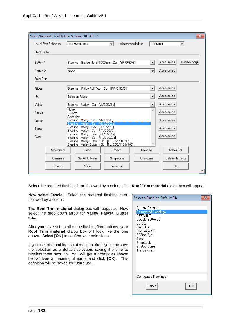
AppliCad – Roof Wizard – Learning Guide V8.1
PAGE 183
Select the required flashing item, followed by a colour. The Roof Trim material dialog box will appear. Now select Fascia. Select the required flashing item, followed by a colour. The Roof Trim material dialog box will reappear. Now select the drop down arrow for Valley, Fascia, Gutter etc.. After you have set up all of the flashing/trim options, your Roof Trim material dialog box will look like the one above. Select [OK] to confirm your selections. If you use this combination of roof trim often, you may save the selection as a default selection, saving the time to reselect them next job. You will get a prompt as shown below; type a meaningful name and click [OK]. This definition will be saved for future use.
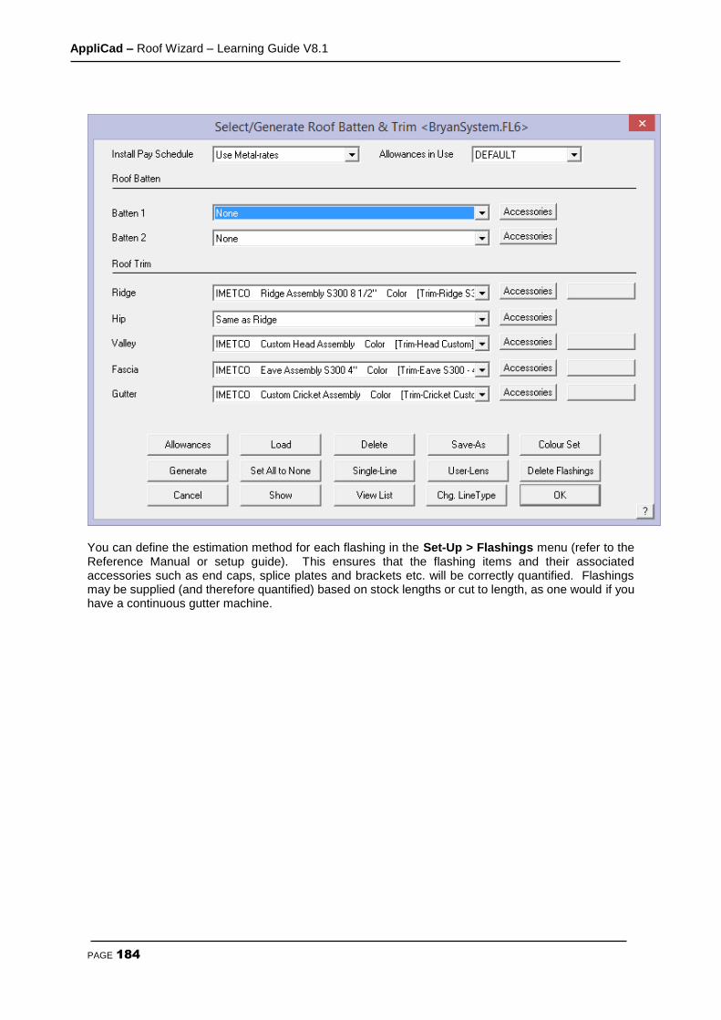
AppliCad – Roof Wizard – Learning Guide V8.1
PAGE 184
You can define the estimation method for each flashing in the Set-Up > Flashings menu (refer to the Reference Manual or setup guide). This ensures that the flashing items and their associated accessories such as end caps, splice plates and brackets etc. will be correctly quantified. Flashings may be supplied (and therefore quantified) based on stock lengths or cut to length, as one would if you have a continuous gutter machine.
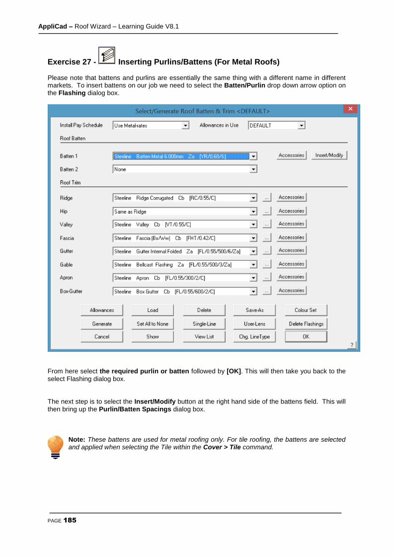
AppliCad – Roof Wizard – Learning Guide V8.1
PAGE 185
Exercise 27 - Inserting Purlins/Battens (For Metal Roofs) Please note that battens and purlins are essentially the same thing with a different name in different markets. To insert battens on our job we need to select the Batten/Purlin drop down arrow option on the Flashing dialog box.
From here select the required purlin or batten followed by [OK]. This will then take you back to the select Flashing dialog box. The next step is to select the Insert/Modify button at the right hand side of the battens field. This will then bring up the Purlin/Batten Spacings dialog box.
Note: These battens are used for metal roofing only. For tile roofing, the battens are selected and applied when selecting the Tile within the Cover > Tile command.
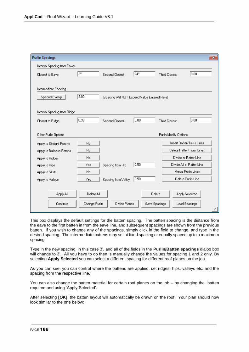
AppliCad – Roof Wizard – Learning Guide V8.1
PAGE 186
This box displays the default settings for the batten spacing. The batten spacing is the distance from the eave to the first batten in from the eave line, and subsequent spacings are shown from the previous batten. If you wish to change any of the spacings, simply click in the field to change, and type in the desired spacing. The intermediate battens may set at fixed spacing or equally spaced up to a maximum spacing. Type in the new spacing, in this case 3’, and all of the fields in the Purlin/Batten spacings dialog box will change to 3’. All you have to do then is manually change the values for spacing 1 and 2 only. By selecting Apply Selected you can select a different spacing for different roof planes on the job As you can see, you can control where the battens are applied, i.e, ridges, hips, valleys etc. and the spacing from the respective line. You can also change the batten material for certain roof planes on the job – by changing the batten required and using ‘Apply-Selected’. After selecting [OK], the batten layout will automatically be drawn on the roof. Your plan should now look similar to the one below:

AppliCad – Roof Wizard – Learning Guide V8.1
PAGE 187
If you wish to turn the battens off so they are no longer displayed, select Set Display from the Tools menu, and set Battens to No. This does not delete them, it just blanks them in this view.
Note: even though we have inserted the battens, they will not yet be estimated. That will be done when we generate the flashing cutting list – using Generate.

AppliCad – Roof Wizard – Learning Guide V8.1
PAGE 188
Exercise 28 - Estimating Flashings Select Flashings from the Cover menu and the following dialog box will appear showing the flashings that you previously selected.
By selecting the Allowances button the following dialog box will appear.

AppliCad – Roof Wizard – Learning Guide V8.1
PAGE 189
Allowances are the values that determine the amount that is added to the measured length for each piece of material up to the stock length. For example, when flashing lengths are calculated, the maximum length for the flashing is now taken into account. The way it works is to divide the given length into a series of equal length pieces. If the length of a run was 35’, and the maximum stock length is 14’, the original length is broken into 3 x 14’. The allowance is then added to each of these pieces. With your allowances now set click [OK]. This will take you back to the Flashing dialog box. From here select Generate and your flashings will be generated, bringing up a dialog box similar to the following. This is the complete list of flashing materials required for the current job, total length of coil plus each individual piece length.

AppliCad – Roof Wizard – Learning Guide V8.1
PAGE 190
Note that the Accessories as previously defined for each flashing category will be listed below the trim list. The list depends entirely on what was previously defined and care must be used to ensure that the accessories have been correctly associated. Review the notes in the Set-up Guide and the Reference Manual for more details.

AppliCad – Roof Wizard – Learning Guide V8.1
PAGE 191
The Cover Command - Tile Roofs
Introduction
Quantity by Coursing or Unit Area - Tiles and Tiles+ Database
Before going ahead and select your tiles for the roof, you have to decide the best method of
determining the tile quantities. You have the choice of generating tile quantities by unit area (ie
tiles per square) or the more precise method of coursing which lays the tiles course by course
and applies a more flexible waste calculation.
In addition you have two tile database structures that you can work with – what AppliCad calls
Tiles database and the Tiles+ database.
The Tiles+ database is a comprehensive database of tiles and accessories plus components,
that is most suited to the UK and European markets, where as the Tiles database is a much
simplified tile database generally suitable for the Australian and USA markets.
Once you have decided which database structure best suits you (call AppliCad if you’re not sure),
you set the database type using Set-Up > Preference Settings > System Preferences. Now
you are ready to quantify your tiles. Later in this Manual explains the differences in more detail.
The Cover command lets you select new tiles, shingles or shakes for this job. You can also apply sarking and generate tile courses.

AppliCad – Roof Wizard – Learning Guide V8.1
PAGE 192
Tile Roofs - TILES Database
Note: This section is only for those who are using the standard Tiles database. If you are using the Tiles+, please skip this section.
Exercise 29 - Select a tile This exercise deals with selecting the tiles (or shingles/shakes) to cover the roof. If you don’t use tiles, you can skip this section. To choose a tile select Cover followed by Select-Tile. This will bring up the following dialog box asking you to select a tile. When you have selected your tile the following dialog box will appear showing the details of the tile you have just selected.
So that the system will automatically cost the correct battens, the operator must select a particular batten size. After the tile is selected and the colour selected, click in the batten prompt box and a list of batten options is displayed. Select the batten to be used and then [OK]. From this tile dialog box you also set the rate of pay that you would like to use by clicking on the selection arrow at the end of the Pay Rate Schedule field. If you have not set any pay rates this will be explained later in Exercise 45. Select the [Acessories] button and the accessory items for the selected tile profile are displayed.
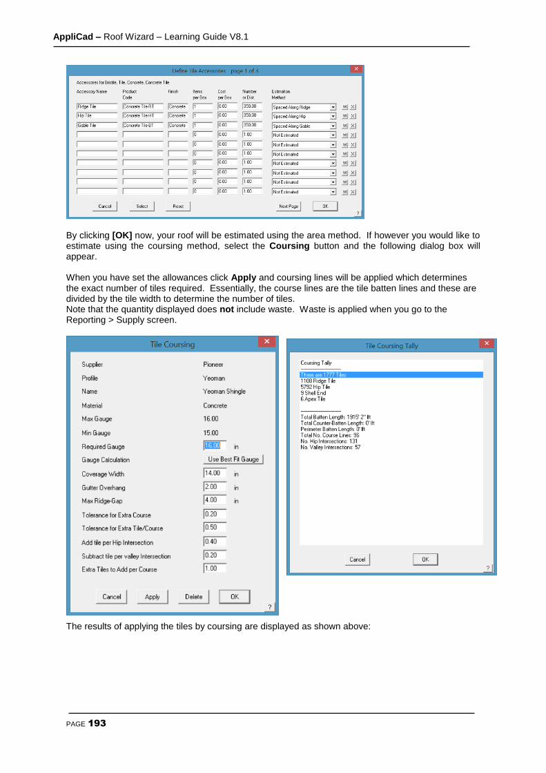
AppliCad – Roof Wizard – Learning Guide V8.1
PAGE 193
By clicking [OK] now, your roof will be estimated using the area method. If however you would like to estimate using the coursing method, select the Coursing button and the following dialog box will appear. When you have set the allowances click Apply and coursing lines will be applied which determines the exact number of tiles required. Essentially, the course lines are the tile batten lines and these are divided by the tile width to determine the number of tiles. Note that the quantity displayed does not include waste. Waste is applied when you go to the Reporting > Supply screen.
The results of applying the tiles by coursing are displayed as shown above:
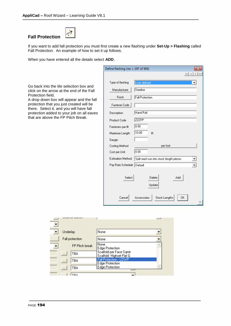
AppliCad – Roof Wizard – Learning Guide V8.1
PAGE 194
Fall Protection
If you want to add fall protection you must first create a new flashing under Set-Up > Flashing called Fall Protection. An example of how to set it up follows. When you have entered all the details select ADD. Go back into the tile selection box and click on the arrow at the end of the Fall Protection field. A drop down box will appear and the fall protection that you just created will be there. Select it, and you will have fall protection added to your job on all eaves that are above the FP Pitch Break.

AppliCad – Roof Wizard – Learning Guide V8.1
PAGE 195
Underlay/Sarking -
(also known variously as vapour barrier, underlayment or insulation) To select a sarking you need to first setup a sarking or insulation material. Select Set-Up > Insulation to create your sarking. Select ADD when you have entered the details.
NOTE: You need to have the Name of your sarking set to Sarking so that it may be selected under the sarking option. Otherwise it is considered a regular insulation material and can be selected under the Insulation option.
Below is an example of how to set it up.
From here we can go back into out Select-Tile dialog box and change Sarking from None to the Sarking we just created, in this case Sarking1. Sarking will now be applied to the entire roof.

AppliCad – Roof Wizard – Learning Guide V8.1
PAGE 196
Tile Roofs - TILES+ database
The coverage command lets you select plain tiles, profile tiles and slate for this job. You can also apply sarking and generate tile quantities by unit area (ie tiles per square) or the more precise method of coursing which lays the tiles course by course and applies a more flexible waste calculation. Note: This section is only for those who are using the Tiles+ database. If you are not using the Tiles+ database, please skip this section. The Tiles+ database is a comprehensive database of tiles, accessories and components that are most suited to the UK and European markets. Certain North American markets will also benefit from the extra details available with the Tiles+ database.
The main difference between the Tiles and Tiles+ databases is the number of accessories available. Within Tiles+ you can define many different types of Ridge, Hip, Valley tiles etc, as well as ridge and eave vent systems and other accessories and components plus material and labour costing. Indeed, every permutation and combination of tiles and accessories may be defined as required for a job. Another important feature about Tiles+ is the fact that we can apply a Tile and a Half or Double Tile (or slate) to the roof and the software will quantify these automatically for us.
Exercise 30 - Select a tile This exercise deals with selecting tiles to cover the roof. If you don’t use tiles, you can skip this section. To choose a tile, select Cover followed by Select-Tile. This will bring up the following dialog box asking you to select a tile.
Note: you will have indicated in the Set-Up > Preference Settings > System Preferences section, which Tiles database you wish to use, either Tiles or Tiles+. Upon selecting Cover > Select-Tile, the relevant database will open up. In this section we are dealing with Tiles+.
In this instance we will use a Redland Heathland tile as it allows us to look at the Tile and a Half usage. Remember that we refer to Tiles but the same rules apply to Slate. When you have selected the tile, click [OK] and the following box will appear.
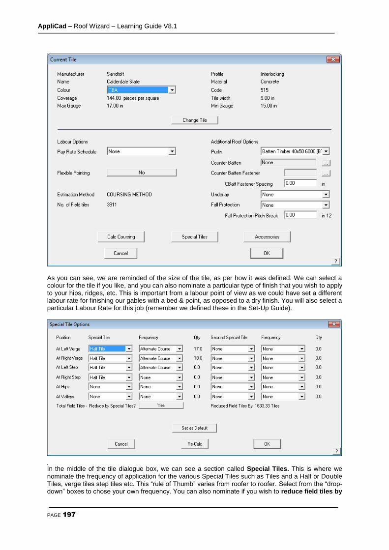
AppliCad – Roof Wizard – Learning Guide V8.1
PAGE 197
As you can see, we are reminded of the size of the tile, as per how it was defined. We can select a colour for the tile if you like, and you can also nominate a particular type of finish that you wish to apply to your hips, ridges, etc. This is important from a labour point of view as we could have set a different labour rate for finishing our gables with a bed & point, as opposed to a dry finish. You will also select a particular Labour Rate for this job (remember we defined these in the Set-Up Guide).
In the middle of the tile dialogue box, we can see a section called Special Tiles. This is where we nominate the frequency of application for the various Special Tiles such as Tiles and a Half or Double Tiles, verge tiles step tiles etc. This “rule of Thumb” varies from roofer to roofer. Select from the “drop-down” boxes to chose your own frequency. You can also nominate if you wish to reduce field tiles by

AppliCad – Roof Wizard – Learning Guide V8.1
PAGE 198
tile + half pieces? This means that you can either quantify for the tile and a halves in addition to the field tiles on the roof (as if there were no tile and a halves), or reduce the field tiles by the correct amount for a more accurate quotation. You may set the definition as a default so it is available for the next job. On the bottom left of the Tiles page, we have the Coursing section. Here is where we can change the coursing values for that tile if required, as well as specify a Gutter Overhang and Ridge Gap. Normally the software will Use best fit gauge to quantify the courses up each slope, but if you needed to, you can “force” the gauge by entering a value in the Required Gauge field (as long as it is between the max and min gauge range). If you wished to do this, you would change the Gauge Calculation to read Use Required Gauge. If you use a Required Gauge the software mathematically works out the number of courses and number of tile widths by dividing the gauge into slope length and eave length. There may be times when the software will round up to the next number of courses or next tile width, which may cause you to over-quantify the number of tiles. To alleviate this problem, we have included the ability to set a Tolerance for both “Courses” and “width” so that if you specify a tolerance of say “0.2” and the software calculates that there are 45.18 courses on a slope, it will round it down to 45 courses, rather than round it up. When you have input the required settings, click on Apply Coursing and you will see that there are a series of lines applied to the roof – these are the actual coursing lines. A value will appear next to the Field Tiles from area field. This is the quantity of tiles required before waste is applied.
Note: if you have elected to use the area method to calculate the tiles – select Calculate Using Area but this will not quantify the tile and a halves or some other accessories. You set the starting preference (Coursing or by Area in the Set-Up > Preference Settings > Systems Preferences option).
When you defined the tile, you may have already defined a size of batten that you would normally use, in which case, that would be indicated here. You can also change that selection on a job-by-job basis. You will also select your material for your Sarking (insulation or underlay). When you have made this selection, select Accessories to nominate the accessories to accompany the tile. When you click Accessories the following box will appear:

AppliCad – Roof Wizard – Learning Guide V8.1
PAGE 199
As you can see, once you have selected the field tile, you can select the accessory type (such as type of Ridge Tile, Hip Tile etc.) available for that profile of tile and what you need for this job. It is important to remember that you can change the accessory items to any one of the options you have previously defined and then add the required components required to install those accessories. The same applies to items like cloaked verge and dry-verge systems. As you can see from the previous page, you can select the appropriate components such as fasteners and clips for the different accessories on the roof. The components are defined as a subset of accessories and may include fasteners. The fasteners were defined within Set-Up > Fasteners. Refer to the Set-Up Guide for more information on this. When you have made your selection, click [Continue] and click Close on the Tile Accessories box. Then click [OK] on the Current Tile box. This essentially completes the selection and application of tiles to the roof and now you go to the costing command to fully quote the job.
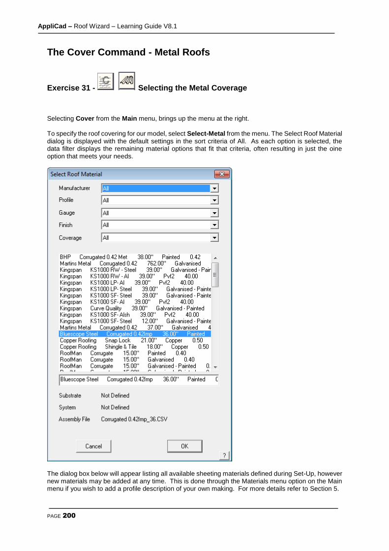
AppliCad – Roof Wizard – Learning Guide V8.1
PAGE 200
The Cover Command - Metal Roofs
Exercise 31 - Selecting the Metal Coverage
Selecting Cover from the Main menu, brings up the menu at the right. To specify the roof covering for our model, select Select-Metal from the menu. The Select Roof Material dialog is displayed with the default settings in the sort criteria of All. As each option is selected, the data filter displays the remaining material options that fit that criteria, often resulting in just the oine option that meets your needs.
The dialog box below will appear listing all available sheeting materials defined during Set-Up, however new materials may be added at any time. This is done through the Materials menu option on the Main menu if you wish to add a profile description of your own making. For more details refer to Section 5.
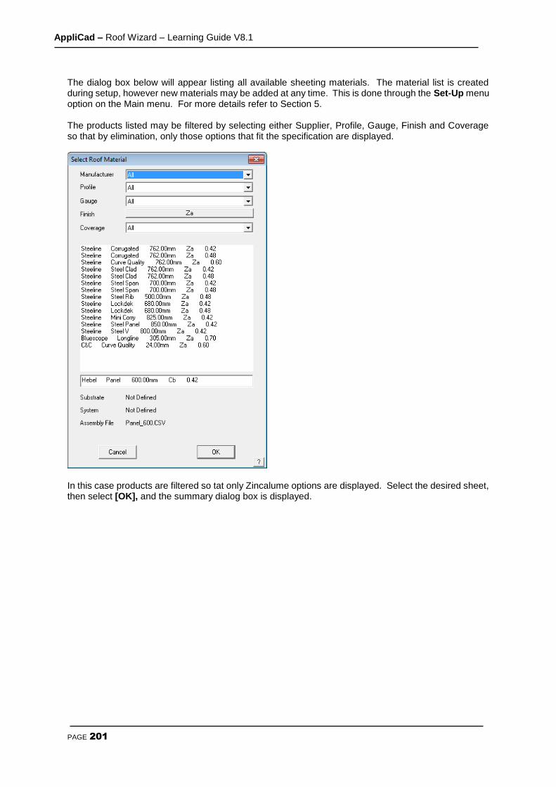
AppliCad – Roof Wizard – Learning Guide V8.1
PAGE 201
The dialog box below will appear listing all available sheeting materials. The material list is created during setup, however new materials may be added at any time. This is done through the Set-Up menu option on the Main menu. For more details refer to Section 5. The products listed may be filtered by selecting either Supplier, Profile, Gauge, Finish and Coverage so that by elimination, only those options that fit the specification are displayed.
In this case products are filtered so tat only Zincalume options are displayed. Select the desired sheet, then select [OK], and the summary dialog box is displayed.
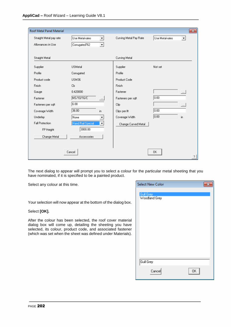
AppliCad – Roof Wizard – Learning Guide V8.1
PAGE 202
The next dialog to appear will prompt you to select a colour for the particular metal sheeting that you have nominated, if it is specified to be a painted product. Select any colour at this time. Your selection will now appear at the bottom of the dialog box. Select [OK]. After the colour has been selected, the roof cover material dialog box will come up, detailing the sheeting you have selected, its colour, product code, and associated fastener (which was set when the sheet was defined under Materials).
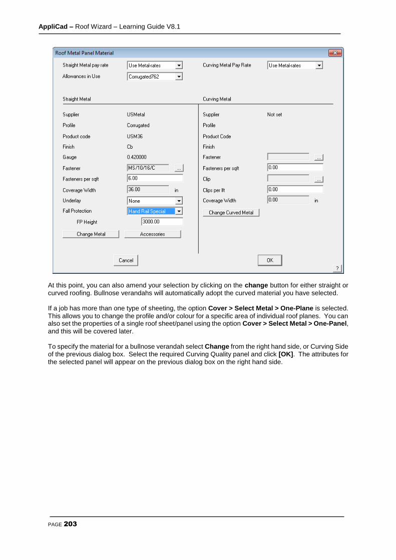
AppliCad – Roof Wizard – Learning Guide V8.1
PAGE 203
At this point, you can also amend your selection by clicking on the change button for either straight or curved roofing. Bullnose verandahs will automatically adopt the curved material you have selected. If a job has more than one type of sheeting, the option Cover > Select Metal > One-Plane is selected. This allows you to change the profile and/or colour for a specific area of individual roof planes. You can also set the properties of a single roof sheet/panel using the option Cover > Select Metal > One-Panel, and this will be covered later. To specify the material for a bullnose verandah select Change from the right hand side, or Curving Side of the previous dialog box. Select the required Curving Quality panel and click [OK]. The attributes for the selected panel will appear on the previous dialog box on the right hand side.

AppliCad – Roof Wizard – Learning Guide V8.1
PAGE 204
The Estimate Command - Metal Roofs
Selecting Estimate from the main menu displays the Estimate menu as displayed to the left. This menu option only applies to metal roofing. It is here you generate the sheet cutting list. The process involves
setting allowances
using the appropriate sheet estimation method (blocks, offcuts or sheets)
From there, you can insert lap direction arrows which will later appear on the roof drawing.
Note: Each method of determining the cut list and sheet placement has advantages and disadvantages, especially as regards waste optimization. The preferred method for your situation will be determined by the style of sheet, the experience of your estimator and the skills of your
installers. Call AppliCad if you wish to discuss the merits of each and which will best suit your company. We have observed, that very few metal roofing contractors in North America are inclined to use some of the material waste reduction techniques developed in Australia and New Zealand – this includes Blocking, Block-Cut, Gen-Offcuts. This is largely due to the style of metal panel used. If you do not attempt to reduce waste by re-using offcut material on your roof, skip these exercses and go straight to Exercise 36.

AppliCad – Roof Wizard – Learning Guide V8.1
PAGE 205

AppliCad – Roof Wizard – Learning Guide V8.1
PAGE 206
Exercise 32 - Setting Allowances The first option in the estimate menu, Allowances, sets the allowances that the software uses for set-backs at ridges hips etc when creating the as built roof planes with the Estimate Offset-Roof command plus other options for the way the roof panels are annotated. When you click [OK], the allowances are saved for use with all subsequent jobs. Note: If your jobs have different allowances, the operator must check and set these allowances for each job. Different allowance files may be created and saved for future use for specific roof systems. To load a previously defined Allowance file select Load and select the required file from the list.
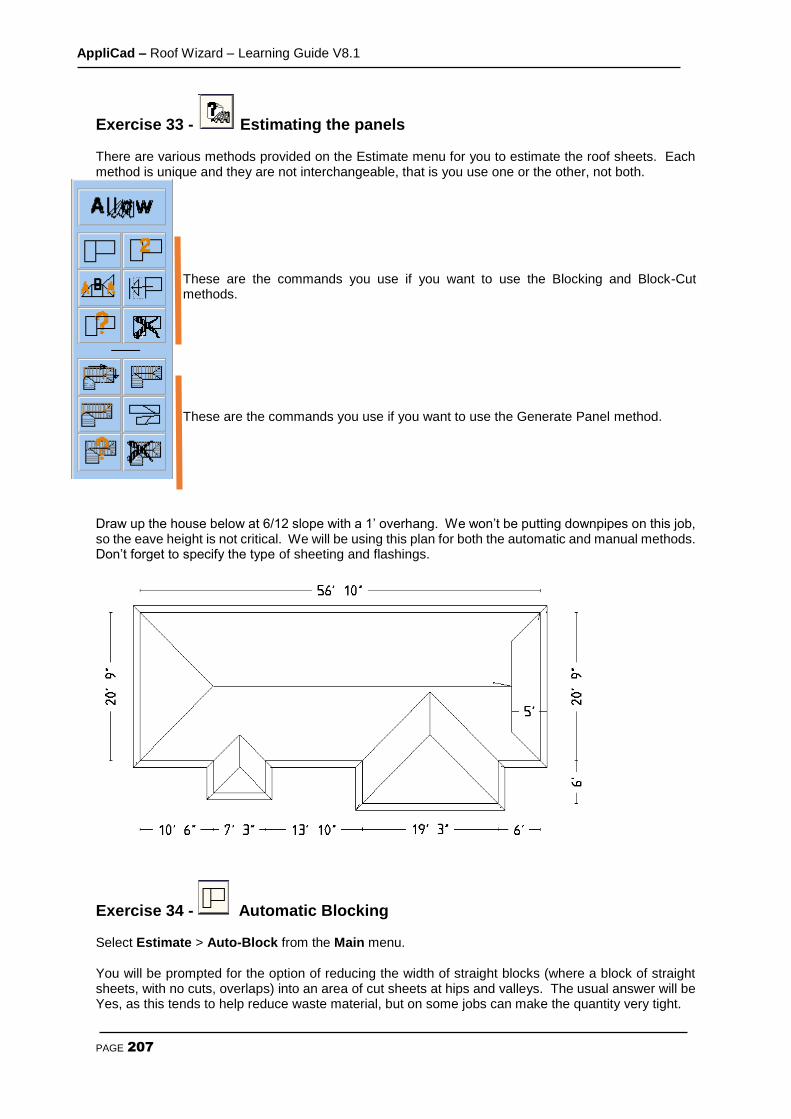
AppliCad – Roof Wizard – Learning Guide V8.1
PAGE 207
Exercise 33 - Estimating the panels There are various methods provided on the Estimate menu for you to estimate the roof sheets. Each method is unique and they are not interchangeable, that is you use one or the other, not both.
These are the commands you use if you want to use the Blocking and Block-Cut methods. These are the commands you use if you want to use the Generate Panel method.
Draw up the house below at 6/12 slope with a 1’ overhang. We won’t be putting downpipes on this job, so the eave height is not critical. We will be using this plan for both the automatic and manual methods. Don’t forget to specify the type of sheeting and flashings.
Exercise 34 - Automatic Blocking Select Estimate > Auto-Block from the Main menu. You will be prompted for the option of reducing the width of straight blocks (where a block of straight sheets, with no cuts, overlaps) into an area of cut sheets at hips and valleys. The usual answer will be Yes, as this tends to help reduce waste material, but on some jobs can make the quantity very tight.
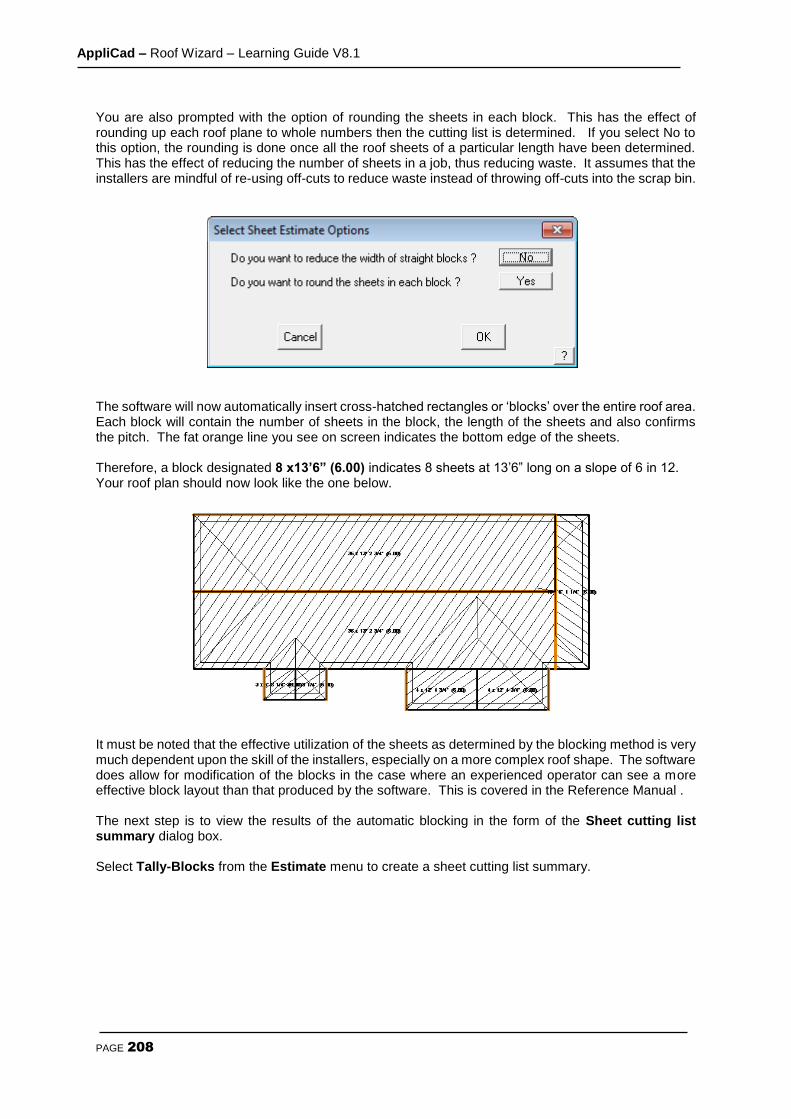
AppliCad – Roof Wizard – Learning Guide V8.1
PAGE 208
You are also prompted with the option of rounding the sheets in each block. This has the effect of rounding up each roof plane to whole numbers then the cutting list is determined. If you select No to this option, the rounding is done once all the roof sheets of a particular length have been determined. This has the effect of reducing the number of sheets in a job, thus reducing waste. It assumes that the installers are mindful of re-using off-cuts to reduce waste instead of throwing off-cuts into the scrap bin.
The software will now automatically insert cross-hatched rectangles or ‘blocks’ over the entire roof area. Each block will contain the number of sheets in the block, the length of the sheets and also confirms the pitch. The fat orange line you see on screen indicates the bottom edge of the sheets. Therefore, a block designated 8 x13’6” (6.00) indicates 8 sheets at 13’6” long on a slope of 6 in 12. Your roof plan should now look like the one below.
It must be noted that the effective utilization of the sheets as determined by the blocking method is very much dependent upon the skill of the installers, especially on a more complex roof shape. The software does allow for modification of the blocks in the case where an experienced operator can see a more effective block layout than that produced by the software. This is covered in the Reference Manual . The next step is to view the results of the automatic blocking in the form of the Sheet cutting list summary dialog box. Select Tally-Blocks from the Estimate menu to create a sheet cutting list summary.

AppliCad – Roof Wizard – Learning Guide V8.1
PAGE 209
The dialog box below will appear. It provides the sheet cutting list and a summary of the Roof Area and the Sheet Area and Total Sheet or coil length.
This completes the section on the automatic blocking method. If you wish to make any changes on an automatically created block layout, there are commands available to make these modifications. These will be covered in the following section where we will look at inserting blocks manually.
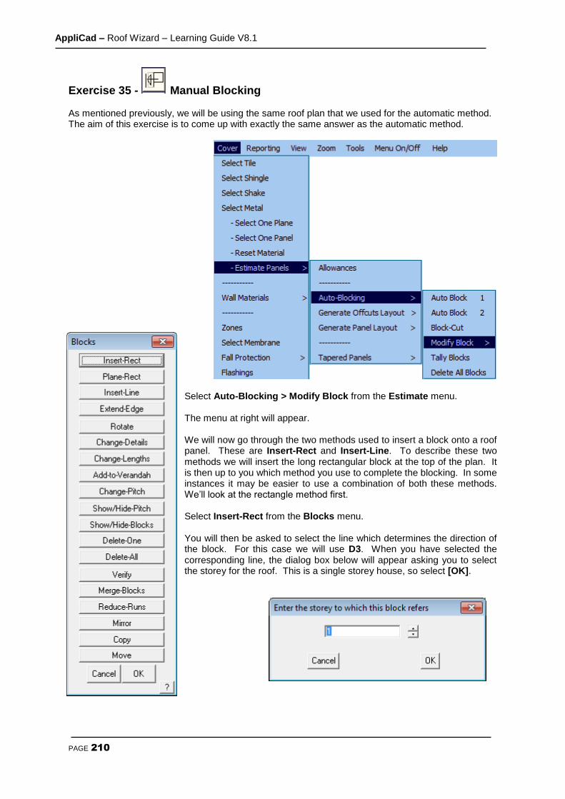
AppliCad – Roof Wizard – Learning Guide V8.1
PAGE 210
Exercise 35 - Manual Blocking As mentioned previously, we will be using the same roof plan that we used for the automatic method. The aim of this exercise is to come up with exactly the same answer as the automatic method.
Select Auto-Blocking > Modify Block from the Estimate menu. The menu at right will appear. We will now go through the two methods used to insert a block onto a roof panel. These are Insert-Rect and Insert-Line. To describe these two methods we will insert the long rectangular block at the top of the plan. It is then up to you which method you use to complete the blocking. In some instances it may be easier to use a combination of both these methods. We’ll look at the rectangle method first. Select Insert-Rect from the Blocks menu. You will then be asked to select the line which determines the direction of the block. For this case we will use D3. When you have selected the corresponding line, the dialog box below will appear asking you to select the storey for the roof. This is a single storey house, so select [OK].
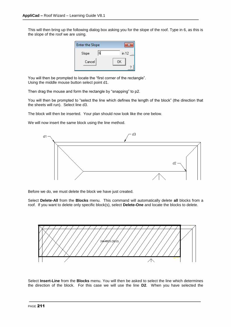
AppliCad – Roof Wizard – Learning Guide V8.1
PAGE 211
This will then bring up the following dialog box asking you for the slope of the roof. Type in 6, as this is the slope of the roof we are using.
You will then be prompted to locate the “first corner of the rectangle”. Using the middle mouse button select point d1. Then drag the mouse and form the rectangle by “snapping” to p2. You will then be prompted to “select the line which defines the length of the block” (the direction that the sheets will run). Select line d3. The block will then be inserted. Your plan should now look like the one below. We will now insert the same block using the line method.
Before we do, we must delete the block we have just created. Select Delete-All from the Blocks menu. This command will automatically delete all blocks from a roof. If you want to delete only specific block(s), select Delete-One and locate the blocks to delete.
Select Insert-Line from the Blocks menu. You will then be asked to select the line which determines the direction of the block. For this case we will use the line D2. When you have selected the

AppliCad – Roof Wizard – Learning Guide V8.1
PAGE 212
corresponding line the following dialog box will appear asking for the pitch of the roof. Enter 6 (as in 6/12 slope).
You will then be prompted to “locate a line to generate a block”. Select line d1.
A hatched square will appear over the hip end. You will then be prompted to “select the line which defines the length of the block”. Select line d2. Your plan should now look like the one at right. The next step is to “extend” the right hand edge of this block so it covers the same area as was created using the automatic method. Select Extend-Edge. You will then be prompted to “ locate a line to move”. Select line d3. You will then be prompted to “locate its new position:”. Snap to point d4. The block will now automatically extend to this point, and the text inside will be updated.
Your plan should now look the one below.
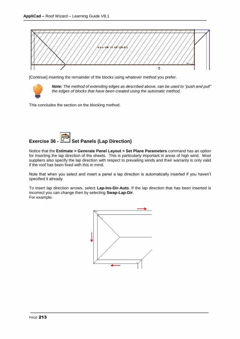
AppliCad – Roof Wizard – Learning Guide V8.1
PAGE 213
[Continue] inserting the remainder of the blocks using whatever method you prefer.
Note: The method of extending edges as described above, can be used to “push and pull” the edges of blocks that have been created using the automatic method.
This concludes the section on the blocking method.
Exercise 36 - Set Panels (Lap Direction) Notice that the Estimate > Generate Panel Layout > Set Plane Parameters command has an option for inserting the lap direction of the sheets. This is particularly important in areas of high wind. Most suppliers also specify the lap direction with respect to prevailing winds and their warranty is only valid if the roof has been fixed with this in mind. Note that when you select and insert a panel a lap direction is automatically inserted if you haven’t specified it already. To insert lap direction arrows, select Lap-Ins-Dir-Auto. If the lap direction that has been inserted is incorrect you can change then by selecting Swap-Lap-Dir. For example:
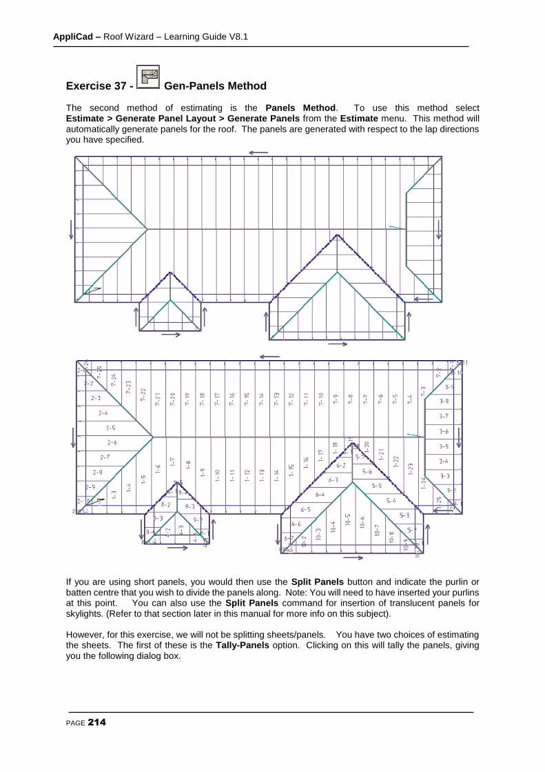
AppliCad – Roof Wizard – Learning Guide V8.1
PAGE 214
Exercise 37 - Gen-Panels Method The second method of estimating is the Panels Method. To use this method select Estimate > Generate Panel Layout > Generate Panels from the Estimate menu. This method will automatically generate panels for the roof. The panels are generated with respect to the lap directions you have specified.
If you are using short panels, you would then use the Split Panels button and indicate the purlin or batten centre that you wish to divide the panels along. Note: You will need to have inserted your purlins at this point. You can also use the Split Panels command for insertion of translucent panels for skylights. (Refer to that section later in this manual for more info on this subject). However, for this exercise, we will not be splitting sheets/panels. You have two choices of estimating the sheets. The first of these is the Tally-Panels option. Clicking on this will tally the panels, giving you the following dialog box.

AppliCad – Roof Wizard – Learning Guide V8.1
PAGE 215
The cutting list is displayed with tiotal number of panels of each length required. Also reported is the total length of coil required for this job and the expected waste factor. This list is also used to create a cutting details report that matches the panel layout drawing. These are standard report oprions. Note also that you can export the cutting list to a CSV text file and to a roll forming machine controller such as AMS Controls, Beck, Proface and others. This reduces errors caused by machine oerators keying incorrect cutting details into the machine controller.
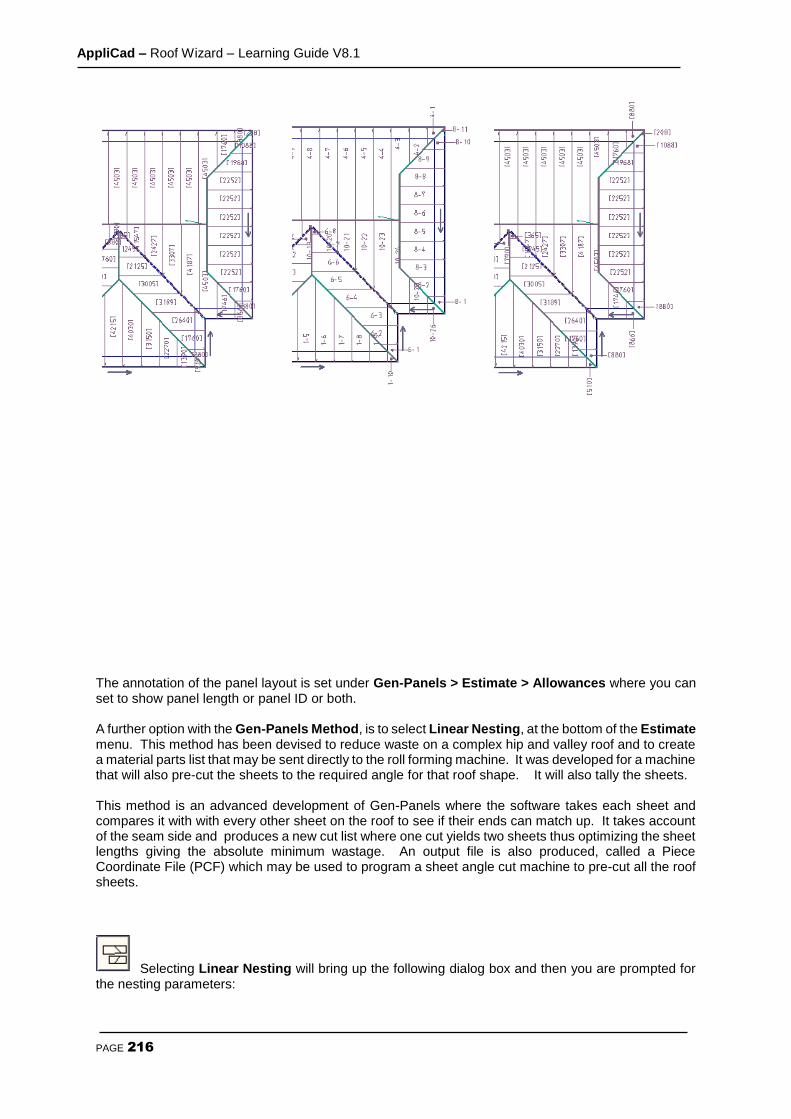
AppliCad – Roof Wizard – Learning Guide V8.1
PAGE 216
The annotation of the panel layout is set under Gen-Panels > Estimate > Allowances where you can set to show panel length or panel ID or both. A further option with the Gen-Panels Method, is to select Linear Nesting, at the bottom of the Estimate menu. This method has been devised to reduce waste on a complex hip and valley roof and to create a material parts list that may be sent directly to the roll forming machine. It was developed for a machine that will also pre-cut the sheets to the required angle for that roof shape. It will also tally the sheets. This method is an advanced development of Gen-Panels where the software takes each sheet and compares it with with every other sheet on the roof to see if their ends can match up. It takes account of the seam side and produces a new cut list where one cut yields two sheets thus optimizing the sheet lengths giving the absolute minimum wastage. An output file is also produced, called a Piece Coordinate File (PCF) which may be used to program a sheet angle cut machine to pre-cut all the roof sheets.
Selecting Linear Nesting will bring up the following dialog box and then you are prompted for the nesting parameters:

AppliCad – Roof Wizard – Learning Guide V8.1
PAGE 217
Set the maximum sheet or panel length you typically use (to allow for easy delivery etc) and then click [OK]. When the sheets have been nested the following dialog box will appear listing all the combined sheet lengths and quantities, including a wastage factor. Nesting provides for the most efficient method for creating the roof cutting list, but does require consideration of what the install team are likely to prefer as a cutting list output. The waste factor would tyically be reduced by 5 - 10%. It should be noted that for many situations, the linear nesting process is totally inappropriate. Use only if you have installers experienced with pre-cutting panels and re-using the offcut material. More details of the complete process are described in Section 5 of the Manual.
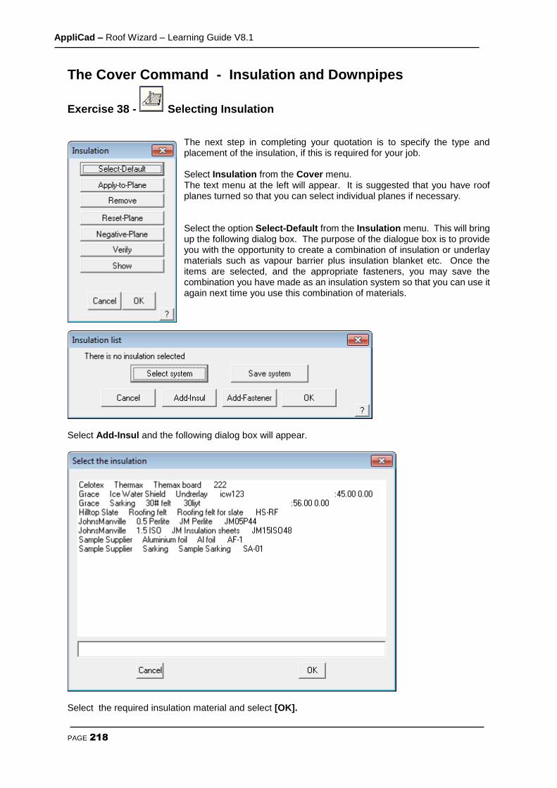
AppliCad – Roof Wizard – Learning Guide V8.1
PAGE 218
The Cover Command - Insulation and Downpipes
Exercise 38 - Selecting Insulation
The next step in completing your quotation is to specify the type and placement of the insulation, if this is required for your job. Select Insulation from the Cover menu. The text menu at the left will appear. It is suggested that you have roof planes turned so that you can select individual planes if necessary. Select the option Select-Default from the Insulation menu. This will bring up the following dialog box. The purpose of the dialogue box is to provide you with the opportunity to create a combination of insulation or underlay materials such as vapour barrier plus insulation blanket etc. Once the items are selected, and the appropriate fasteners, you may save the combination you have made as an insulation system so that you can use it again next time you use this combination of materials.
Select Add-Insul and the following dialog box will appear.
Select the required insulation material and select [OK].
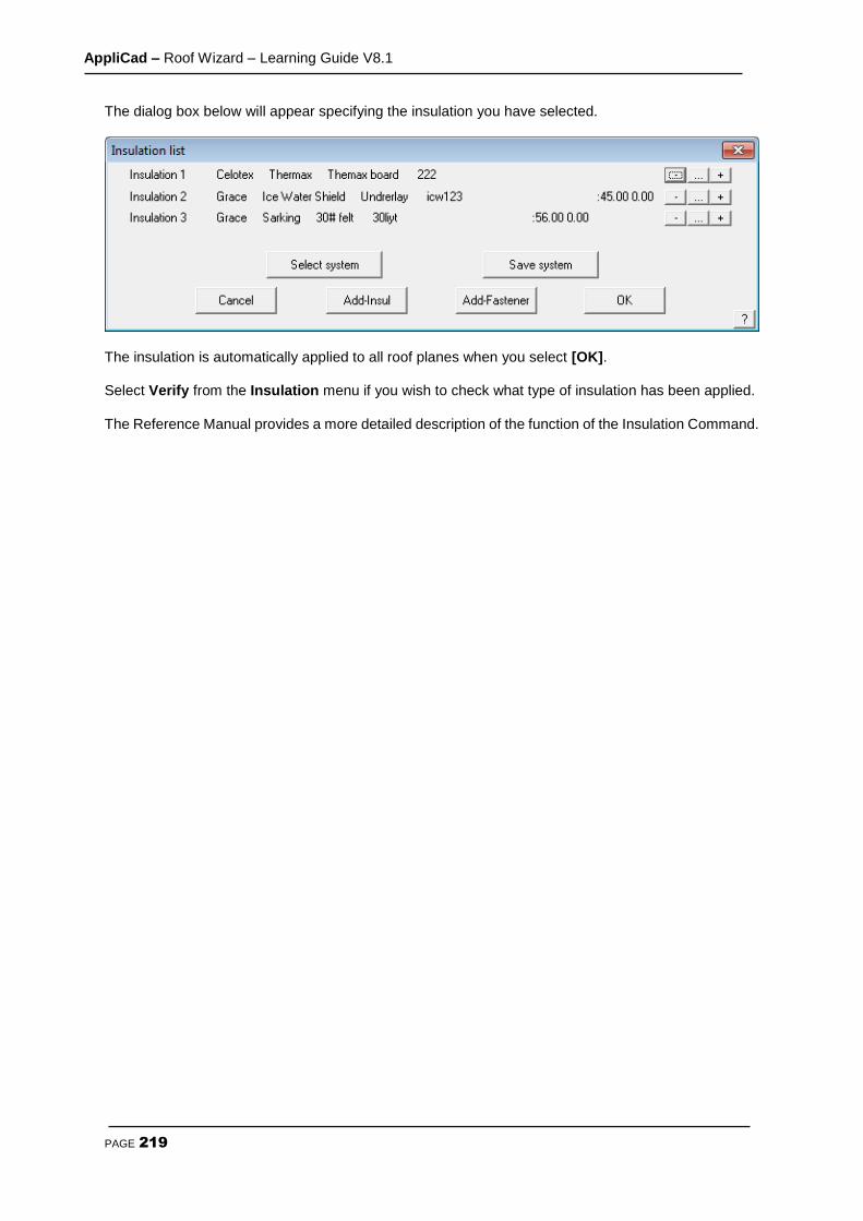
AppliCad – Roof Wizard – Learning Guide V8.1
PAGE 219
The dialog box below will appear specifying the insulation you have selected.
The insulation is automatically applied to all roof planes when you select [OK]. Select Verify from the Insulation menu if you wish to check what type of insulation has been applied. The Reference Manual provides a more detailed description of the function of the Insulation Command.

AppliCad – Roof Wizard – Learning Guide V8.1
PAGE 220
Exercise 39 - Selecting Downpipes The last step that remains to be done as far as your roof cover quotation is concerned, is to specify the position and type of down pipes. Select Down pipes from the Coverage menu.
Select the required downpipe select [OK]. The Select new colour dialog box will appear. Select any colour and select [OK]. Now that we have specified the type of down pipe we will be using, the next step is to position them around the house. Select Insert from the Down pipe menu. You will now be prompted to Locate a line to insert the down pipe on.
Using the left mouse button, locate an eave line, remembering that where you select the line will be the position of the down pipe and check the optional items that you need for this job. .

AppliCad – Roof Wizard – Learning Guide V8.1
PAGE 221
Position the down pipes as per the drawing below:
After selecting an eave line, the following dialog box will appear. The height of gutter is read from the eave height value that you specified when you first created the roof. If the eave height is different, in the case of a sloping building site, then you may change the value determined by the software. You also have three options for the base of the down pipe - shoe, nothing and elbow. Select nothing for this example and then [OK]. This finishes the definition of downpipes. Obviously, if you are not supplying downpipes on a job, you do not have to add them to your job. The costing process will not count them if they’re not there. Having finished defining the various roof cover materials, it would be useful to Save the job at this point. From the pulldown menu select File Save, and type in the project or customer name and add the job name, then select [OK]. Ensure that Preview is checked so that the preview picture is displayed next time you go looking for this job. If you already have a job of similar shape and detail of the same name, you will have to select File Save-As. This allows the operator to use an existing job, make slight modifications and save as a different name for later recall.

AppliCad – Roof Wizard – Learning Guide V8.1
PAGE 222
The Cover Command – BUR/Single Ply Roofing
The roof assembly we will be drawing, is a multi-layered structure made up of several discrete plies, with the following specifications:
1 layer of JM ISO 2” 1 layer of JM Perlite 0.5” Mechanically fastened with screws and plates – 2 every 1 sq Layer of ashphalt at 10 lbs per sq 1 layer of JM Glass 6 Layer of ashphalt at 10 lbs per sq 1 layer of JM Glass 6 Layer of ashphalt at 10 lbs per sq 1 layer of JM Glass 6 Layer of ashphalt at 14 lbs per sq 1 layer of JM glass cap
Our roof structure for this exercise will be a concrete slab with a parapet wall around all sides 2’ high. The edge detail all around is:
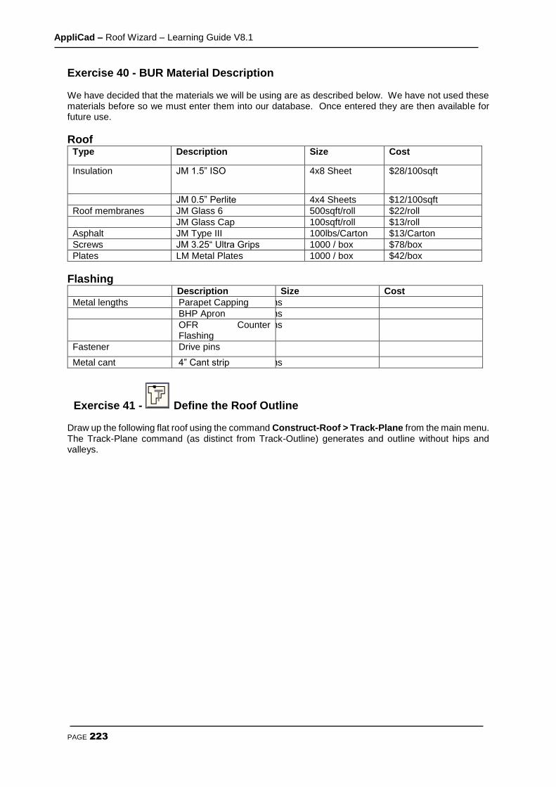
AppliCad – Roof Wizard – Learning Guide V8.1
PAGE 223
Exercise 40 - BUR Material Description We have decided that the materials we will be using are as described below. We have not used these materials before so we must enter them into our database. Once entered they are then available for future use.
Roof Type Description Size Cost
Insulation JM 1.5” ISO 4x8 Sheet $28/100sqft
JM 0.5” Perlite 4x4 Sheets $12/100sqft
Roof membranes JM Glass 6 500sqft/roll $22/roll
JM Glass Cap 100sqft/roll $13/roll
Asphalt JM Type III 100lbs/Carton $13/Carton
Screws JM 3.25“ Ultra Grips 1000 / box $78/box
Plates LM Metal Plates 1000 / box $42/box
Flashing Description Size Cost
Metal lengths Parapet Capping 20ft lengths $2/ ft
BHP Apron 20ft lengths $2/ ft
OFR Counter Flashing
20ft lengths $2/ ft
Fastener Drive pins 2 per ft $0.10 ea
Metal cant 4” Cant strip 15ft lengths $2 / ft
Exercise 41 - Define the Roof Outline Draw up the following flat roof using the command Construct-Roof > Track-Plane from the main menu. The Track-Plane command (as distinct from Track-Outline) generates and outline without hips and valleys.

AppliCad – Roof Wizard – Learning Guide V8.1
PAGE 224
The Construct Roof > Track Outline - Plane outline generator dialog looks like the illustration below, and allows you to input the perimeter dimensions and direction by clicking the direction buttons. You may also simply type r225 for a line created to the right, 225 feet long. Once you get to the second last perimeter line, simply select C {enter} or Close and Close Square. The system will automatically compute the correct geometry to close the perimeter and draw the remaining outline. Check that the last two dimensions are correct. If they are, then you may proceed to the next step. At this stage the lines are construction lines only and don’t really exist, until we select F {enter} or Finish on the dialog box.
If they are not correct, then the information is incorrect or you made a mistake in setting the perimeter dimensions. In the event of a mistake, select Stepback until you delete the wrong line and re-insert it. Once complete with cross-hatching to represent our roof surface, you are ready to get an immediate roof geometry summary. Select Tools > Tally-Quantities from the main menu and the result is displayed.

AppliCad – Roof Wizard – Learning Guide V8.1
PAGE 225
Exercise 42 - Apply the Roof Insulation We now need to select materials and apply them to our roof as a roof material system made up of various plies. Working up from the roof base, we will select each material in turn. While the order does not matter from a take-off point of view, it certainly helps in the interpretation to have the materials listed in the order they are to be laid. We will start with the underlay.
Using the command from the main menu Cover > Insulation > Select-Default, select the types of insulation and the screws and plates with the Add-Insul and Add-Fastener buttons. Since it is likely you will use this same order of material in the future, you may save it as a “system” so that you can recall it again pre-defined. To save it select the Save System button and type in a system name to describe it when prompted. Notice on the right hand side of this dialog box three buttons. These are used to delete, change a line item relating to that material ply or add a ply before the line item.
Exercise 43 - Apply the Roof Material. When you have defined your insulation, select [OK], to finish and go to the next step, which is to add the roof cover material – the Built-Up Roof system. Using Cover > Select-Membrane > Select-Default, select the plies and fasteners (asphalt) as you did for insulation. You may also save a set of plies as a
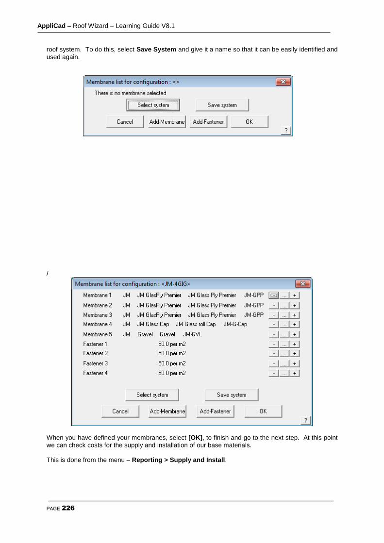
AppliCad – Roof Wizard – Learning Guide V8.1
PAGE 226
roof system. To do this, select Save System and give it a name so that it can be easily identified and used again.
/
When you have defined your membranes, select [OK], to finish and go to the next step. At this point we can check costs for the supply and installation of our base materials. This is done from the menu – Reporting > Supply and Install.
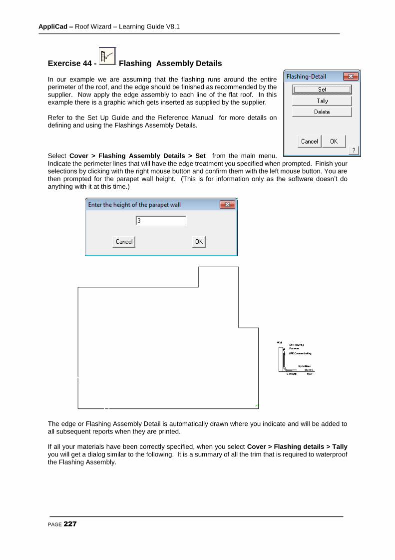
AppliCad – Roof Wizard – Learning Guide V8.1
PAGE 227
Exercise 44 - Flashing Assembly Details In our example we are assuming that the flashing runs around the entire perimeter of the roof, and the edge should be finished as recommended by the supplier. Now apply the edge assembly to each line of the flat roof. In this example there is a graphic which gets inserted as supplied by the supplier. Refer to the Set Up Guide and the Reference Manual for more details on defining and using the Flashings Assembly Details. Select Cover > Flashing Assembly Details > Set from the main menu. Indicate the perimeter lines that will have the edge treatment you specified when prompted. Finish your selections by clicking with the right mouse button and confirm them with the left mouse button. You are then prompted for the parapet wall height. (This is for information only as the software doesn’t do anything with it at this time.)
The edge or Flashing Assembly Detail is automatically drawn where you indicate and will be added to all subsequent reports when they are printed. If all your materials have been correctly specified, when you select Cover > Flashing details > Tally you will get a dialog similar to the following. It is a summary of all the trim that is required to waterproof the Flashing Assembly.
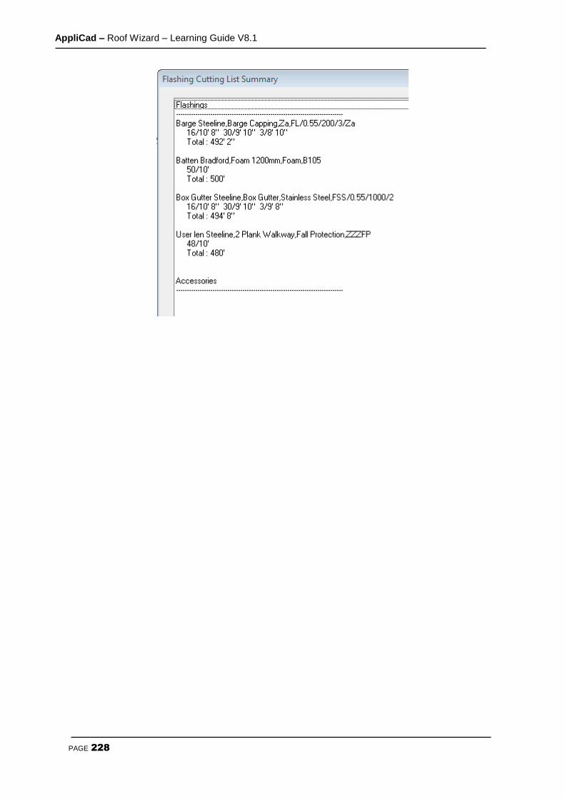
AppliCad – Roof Wizard – Learning Guide V8.1
PAGE 228
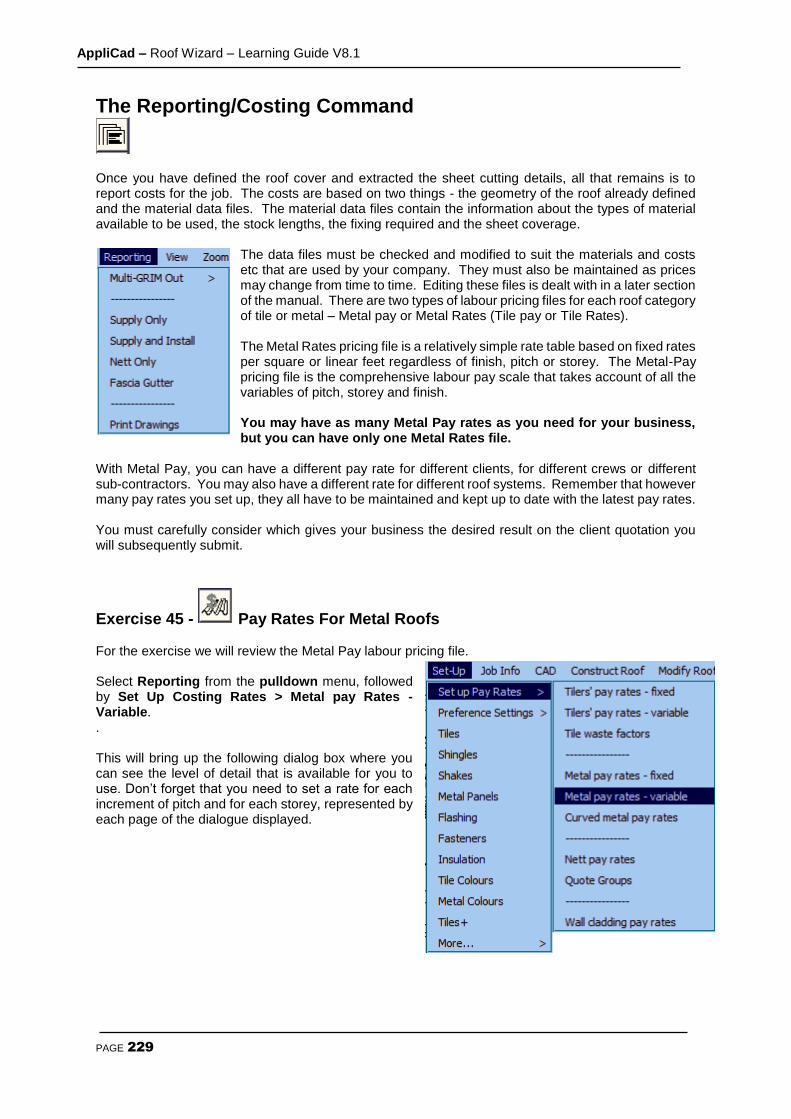
AppliCad – Roof Wizard – Learning Guide V8.1
PAGE 229
The Reporting/Costing Command
Once you have defined the roof cover and extracted the sheet cutting details, all that remains is to report costs for the job. The costs are based on two things - the geometry of the roof already defined and the material data files. The material data files contain the information about the types of material available to be used, the stock lengths, the fixing required and the sheet coverage.
The data files must be checked and modified to suit the materials and costs etc that are used by your company. They must also be maintained as prices may change from time to time. Editing these files is dealt with in a later section of the manual. There are two types of labour pricing files for each roof category of tile or metal – Metal pay or Metal Rates (Tile pay or Tile Rates). The Metal Rates pricing file is a relatively simple rate table based on fixed rates per square or linear feet regardless of finish, pitch or storey. The Metal-Pay pricing file is the comprehensive labour pay scale that takes account of all the variables of pitch, storey and finish. You may have as many Metal Pay rates as you need for your business, but you can have only one Metal Rates file.
With Metal Pay, you can have a different pay rate for different clients, for different crews or different sub-contractors. You may also have a different rate for different roof systems. Remember that however many pay rates you set up, they all have to be maintained and kept up to date with the latest pay rates. You must carefully consider which gives your business the desired result on the client quotation you will subsequently submit.
Exercise 45 - Pay Rates For Metal Roofs For the exercise we will review the Metal Pay labour pricing file. Select Reporting from the pulldown menu, followed by Set Up Costing Rates > Metal pay Rates - Variable. . This will bring up the following dialog box where you can see the level of detail that is available for you to use. Don’t forget that you need to set a rate for each increment of pitch and for each storey, represented by each page of the dialogue displayed.
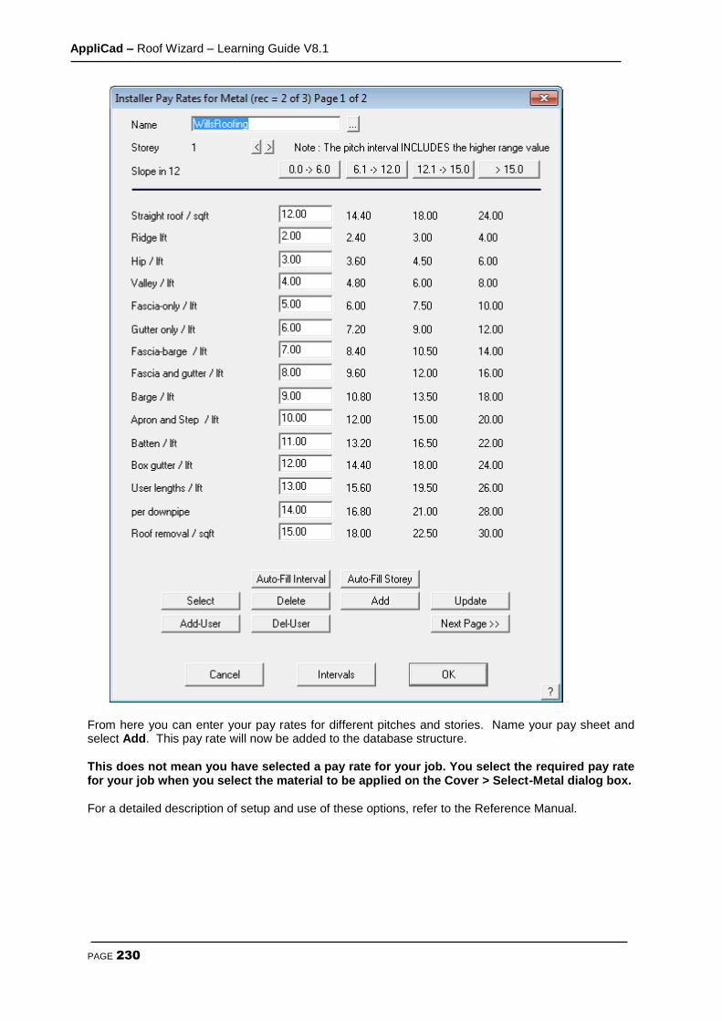
AppliCad – Roof Wizard – Learning Guide V8.1
PAGE 230
From here you can enter your pay rates for different pitches and stories. Name your pay sheet and select Add. This pay rate will now be added to the database structure. This does not mean you have selected a pay rate for your job. You select the required pay rate for your job when you select the material to be applied on the Cover > Select-Metal dialog box. For a detailed description of setup and use of these options, refer to the Reference Manual.

AppliCad – Roof Wizard – Learning Guide V8.1
PAGE 231
Exercise 46 - Pay Rates for Tile Roofs Select Reporting > Setup Costing Rates > Tiler’s pay rates - variable from the Main menu. The Installer pay rates dialog box will appear.
It contains all of the installer labour rates for the individual roofing components in either squares or lineal feet, depending on the item, and a different value is possible for each range of roof pitch. You can change the number of intervals and their spacing by clicking Intervals. For the exercise, type in a name, change a few of the values to suit the rates that your company uses and select Add. These rates are saved as soon as you select Add. If you want to you can save a number of different installer rates. When you have chosen the rate that you would like to use click on [OK].
Note: This does not mean you have selected a pay rate for your job. You select the required pay rate for your job when you select the material to be applied on the Cover > Select-Metal dialog box. For a detailed description of setup and use of these options, refer to Section 3.
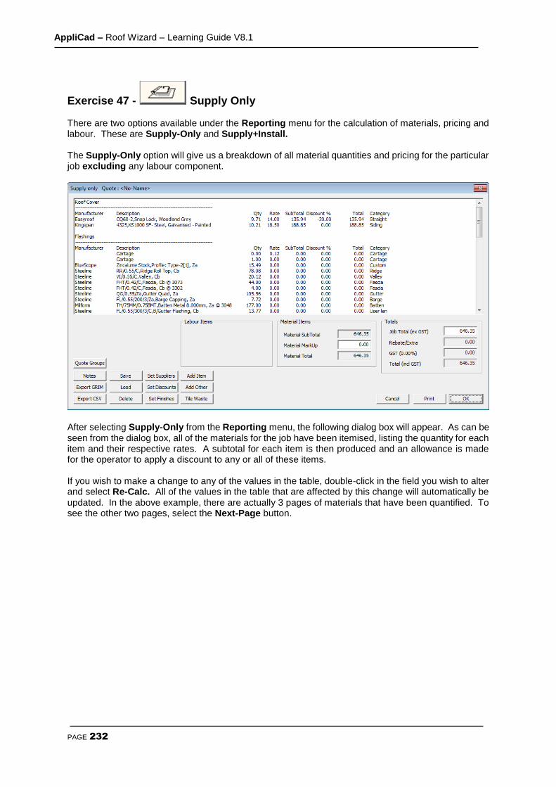
AppliCad – Roof Wizard – Learning Guide V8.1
PAGE 232
Exercise 47 - Supply Only There are two options available under the Reporting menu for the calculation of materials, pricing and labour. These are Supply-Only and Supply+Install. The Supply-Only option will give us a breakdown of all material quantities and pricing for the particular job excluding any labour component.
After selecting Supply-Only from the Reporting menu, the following dialog box will appear. As can be seen from the dialog box, all of the materials for the job have been itemised, listing the quantity for each item and their respective rates. A subtotal for each item is then produced and an allowance is made for the operator to apply a discount to any or all of these items. If you wish to make a change to any of the values in the table, double-click in the field you wish to alter and select Re-Calc. All of the values in the table that are affected by this change will automatically be updated. In the above example, there are actually 3 pages of materials that have been quantified. To see the other two pages, select the Next-Page button.

AppliCad – Roof Wizard – Learning Guide V8.1
PAGE 233
If you wish to insert any notes onto the client quotation form, select the Notes button. The following dialog box will appear. From here select the form that you would like to add notes to, bringing up the following dialog box.
Selecting the Add-Predef-Note allows you to select from a list of pre-defined notes:
Selecting Check/Add Notes allows you to modify or add to the selected notes that will be inserted on the quotation or proposal.
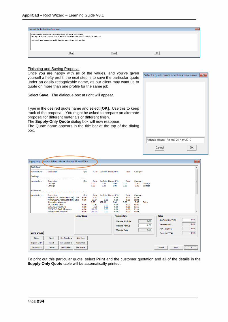
AppliCad – Roof Wizard – Learning Guide V8.1
PAGE 234
Finishing and Saving Proposal Once you are happy with all of the values, and you’ve given yourself a hefty profit, the next step is to save the particular quote under an easily recognizable name, as our client may want us to quote on more than one profile for the same job. Select Save. The dialogue box at right will appear. Type in the desired quote name and select [OK]. Use this to keep track of the proposal. You might be asked to prepare an alternate proposal for different materials or different finish. The Supply-Only Quote dialog box will now reappear. The Quote name appears in the title bar at the top of the dialog box.
To print out this particular quote, select Print and the customer quotation and all of the details in the Supply-Only Quote table will be automatically printed.

AppliCad – Roof Wizard – Learning Guide V8.1
PAGE 235
Exercise 48 - Supply+Install The Supply+Install option will give us a breakdown of all material quantities and pricing for the particular job including any labour component. After selecting Supply+Install from the Reporting menu, the following dialog box will appear.
As you can see, the dialog box is very similar to the one that appears for Supply-Only. The difference is that there is now a button marked Labour subtotal. Underneath this button, there is a field to add a labour markup, and then a labour total. Click on the Labour subtotal button. The following dialog box will appear.
The Quantity, Rate and Total for each individual roofing item are listed. Experiment with some of the labour costings and notice the effects to the totals when you change them. The procedure for recalculating, saving and printing a quote is identical to that for Supply-Only as described above.

AppliCad – Roof Wizard – Learning Guide V8.1
PAGE 236
Exercise 49 - Printing Reports To print your quotes. Select print from the Supply + Install dialog box and the following dialog box will appear.
The buttons next to each of the eleven drawings toggle between Print and Do not print. Select quotation letter as the report to print, and then select [OK]. At this point the software will retrieve the drawing of the roof and insert the relevant information in accordance with the information set up in Job Info e.g. site address etc. and any other information that you may have specified to appear on the drawing by way of key text strings. This process will be visible on the screen.
The Windows Print dialog box will then appear. If we had a printer connected, we would select [OK], and the Roof Drawing would automatically be printed. After the drawing has been printed, the roof model will be redrawn on the screen.

AppliCad – Roof Wizard – Learning Guide V8.1
PAGE 237
The Reporting/Drawings command
The final step in the quotation process is the printing of the drawings.
Exercise 50 - Printing Drawings To print your drawings, select Reporting > Drawings from the main menu, and the following dialog box will appear. Select the drawings that you would like to print, and then select [OK].

AppliCad – Roof Wizard – Learning Guide V8.1
PAGE 238
Wall Creation and Modification The purpose of the following tutorial is to familiarize you with the process of creating a wall in 3D from an Architectural drawing. The Walls option may not be available if you have not purchased the Walls module. The modelling tutorials will be divided into two sections. The first section will explain how to use the Track-Walls command, and the second will explain about Projecting Walls from either the outline we have drawn, or from a Roofing job already completed. This will be followed by tutorials on coverage and costing.
Before we start we make sure that your Preferences are set to Feet/Inches, Slope and American. This is set under the Set-Up > Preference Settings > Systems Preferences menu.
Exercise 1 - Track-Outline First select the Walls option from the Main menu We will use Track-Walls to input a wall outline as this will be the most usual method of outline definition. Imagine we have received a job to cost via the fax. The drawing is fully dimensioned. Select Track-Walls . A horizontal and vertical line will appear on the screen forming a cross. The intersection of these two lines is the point used for plotting or locating various points. At the bottom of the screen in the prompt area, it will ask you to Locate start point. This works in the same way as when using our roofing software. Using the left mouse button, locate a point anywhere on the screen. The Wall Direction and distance dialog box will now appear. (see below) :
The buttons marked Left, Right, Up and Down, allow you to navigate around the plan as you put in the external brickwork measurements. The angled lines are for walls that are at 45 degrees. The Hor-Ver button is to allow the operator to insert wall lines that are not square with the balance of the structure for example, 12’ along and 35’ up.
AppliCad – Roof Wizard – Learning Guide V8.1
PAGE 239
After selecting the direction of the wall that you want to draw in, or by typing in the angle in the direction field, the Distance field will be highlighted. Type in the length of the wall and select Insert. You are now ready to put in the next wall. Starting at the bottom left hand corner of the house, select Up, and then type in 24’ for the length of the wall. Select Insert. Now select Right and type in 24, then Insert. You could also type R24 in the direction field for the same result. If you make a mistake, select Stepback and redo the wall. Following is a simple “L” shaped house that we will use in this example.
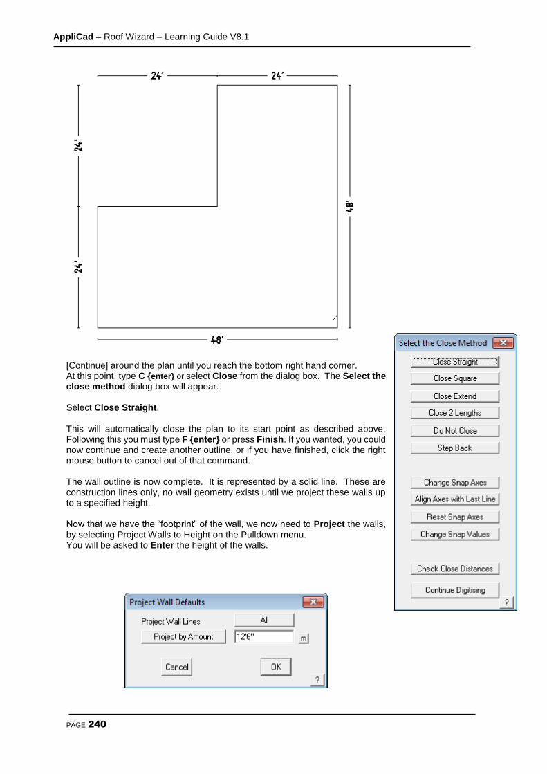
AppliCad – Roof Wizard – Learning Guide V8.1
PAGE 240
[Continue] around the plan until you reach the bottom right hand corner. At this point, type C {enter} or select Close from the dialog box. The Select the close method dialog box will appear. Select Close Straight.
This will automatically close the plan to its start point as described above. Following this you must type F {enter} or press Finish. If you wanted, you could now continue and create another outline, or if you have finished, click the right mouse button to cancel out of that command. The wall outline is now complete. It is represented by a solid line. These are construction lines only, no wall geometry exists until we project these walls up to a specified height. Now that we have the “footprint” of the wall, we now need to Project the walls, by selecting Project Walls to Height on the Pulldown menu. You will be asked to Enter the height of the walls.

AppliCad – Roof Wizard – Learning Guide V8.1
PAGE 241
Enter 12’6” and click [OK]. At this point, your wall lines may disappear from view. Don’t be too alarmed at this point. It is simply that the software has drawn lines over lines and this causes them to be invisible.
To make them re-appear, we may need to Repaint the screen, using the Paintbrush icon, located on the left of the screen.
Viewing your Walls At the moment, you are looking at a top view of the building, and you may want to take a look from a different angle. To do this, select View from the Top menu, and then selecting the appropriate view. In this case I have used ISO.
After changing the view, you may not be able to see any or all of the building. If this is the case, we need to “Fit” the view to the screen by clicking on the Fit button found on the left menu.
Your view should now look something like the one above. This completes the first exercise using Track-Outline. It is advisable that you save this job as you will need to re-open it later.
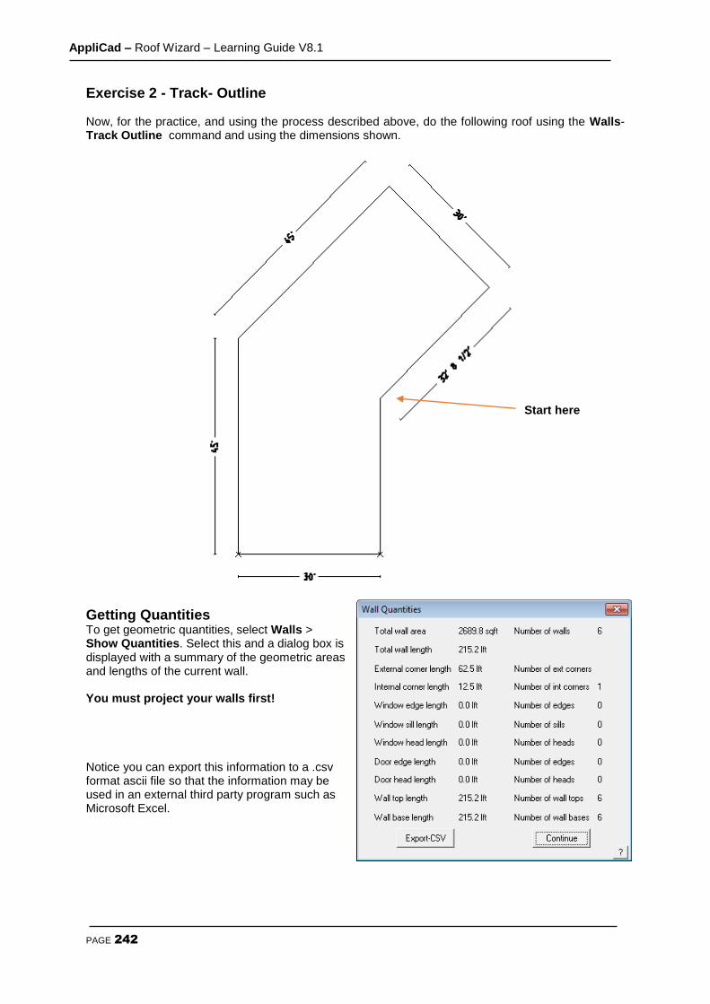
AppliCad – Roof Wizard – Learning Guide V8.1
PAGE 242
Exercise 2 - Track- Outline Now, for the practice, and using the process described above, do the following roof using the Walls-Track Outline command and using the dimensions shown.
Getting Quantities To get geometric quantities, select Walls > Show Quantities. Select this and a dialog box is displayed with a summary of the geometric areas and lengths of the current wall. You must project your walls first! Notice you can export this information to a .csv format ascii file so that the information may be used in an external third party program such as Microsoft Excel.
Start here

AppliCad – Roof Wizard – Learning Guide V8.1
PAGE 243
Exercise 3 - Track-Outline Now that you have input these relatively simple wall designs, try the next one. Remember, if you make a mistake keying in the wall length, select Step Back and re-insert the correct value.
To To begin the next exercise, select File from the pulldown menu at the top of the screen and select New. This will automatically clear the screen of the current job. As before, select Walls from the main menu, then Track-Walls. Start at the point indicated and work in a clockwise direction around the wall line. To achieve this drawing, follow the outline above and project the walls to a height of 12’. Select View- ISO, and you should have a result like the one shown.
Inserting Gable Ends If there are Vertical Planes on the building you must tell the software where they are. To do this select Walls > Gable. This will bring up the following dialog box.
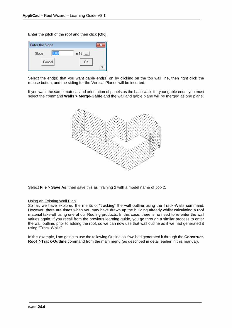
AppliCad – Roof Wizard – Learning Guide V8.1
PAGE 244
Enter the pitch of the roof and then click [OK].
Select the end(s) that you want gable end(s) on by clicking on the top wall line, then right click the mouse button, and the siding for the Vertical Planes will be inserted. If you want the same material and orientation of panels as the base walls for your gable ends, you must select the command Walls > Merge-Gable and the wall and gable plane will be merged as one plane.
Select File > Save As, then save this as Training 2 with a model name of Job 2.
Using an Existing Wall Plan So far, we have explored the merits of “tracking” the wall outline using the Track-Walls command. However, there are times when you may have drawn up the building already whilst calculating a roof material take-off using one of our Roofing products. In this case, there is no need to re-enter the wall values again. If you recall from the previous learning guide, you go through a similar process to enter the wall outline, prior to adding the roof, so we can now use that wall outline as if we had generated it using “Track-Walls”. In this example, I am going to use the following Outline as if we had generated it through the Construct-Roof >Track-Outline command from the main menu (as described in detail earlier in this manual).

AppliCad – Roof Wizard – Learning Guide V8.1
PAGE 245
Add a metal or tile roof to it with a slope of 5/12 and an eave overhang of 1’6”. Say No to Change in Overhangs, Vertical Planes and Barge Lines, so that you will end up with a roof looking like this:
Now that the software already knows the wall outline to generate the roof, we can use that same wall outline to generate the walls.
Projecting the Walls To generate the walls for the previous outline, select Walls from the main menu, and then select Project. The software already knows what the height of the walls should be, based on the eave height that you used and the eave overhang, but you can change it at this point if you wish.

AppliCad – Roof Wizard – Learning Guide V8.1
PAGE 246
After clicking [OK], you will notice that the walls are generated automatically. And you will end up with a view like this;
Finally, as there may be too much information appearing on the screen, we may want to “turn-off” the roof temporarily, so that we can concentrate on the walls. You do this by selecting Tools from the pulldown menu then Set Display. You can now select which part of the view you wish to turn off.
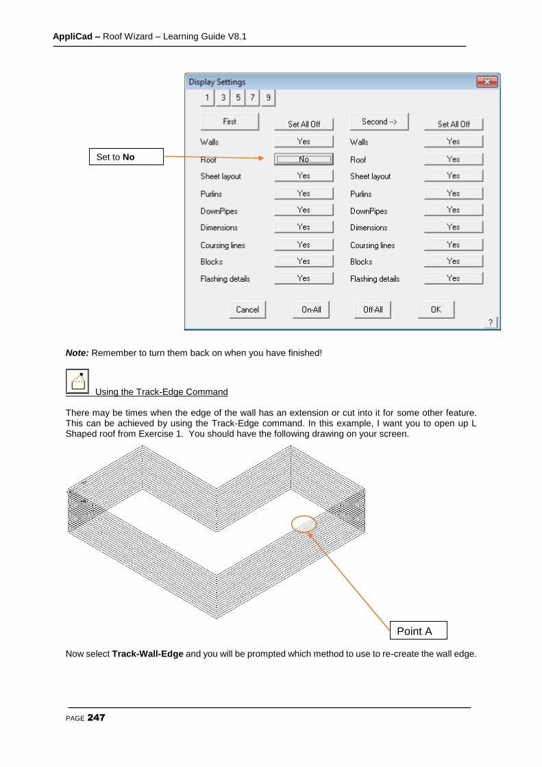
AppliCad – Roof Wizard – Learning Guide V8.1
PAGE 247
Note: Remember to turn them back on when you have finished!
Using the Track-Edge Command There may be times when the edge of the wall has an extension or cut into it for some other feature. This can be achieved by using the Track-Edge command. In this example, I want you to open up L Shaped roof from Exercise 1. You should have the following drawing on your screen.
Now select Track-Wall-Edge and you will be prompted which method to use to re-create the wall edge.
Point A
Set to No
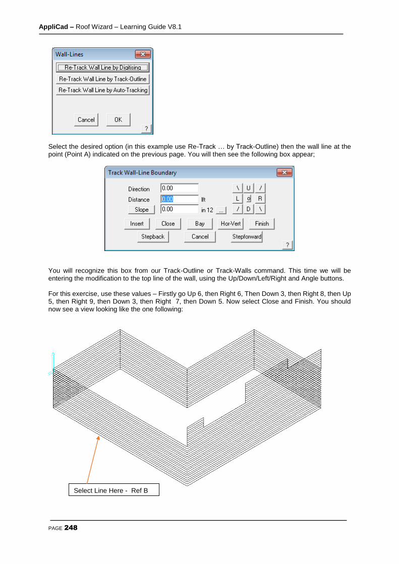
AppliCad – Roof Wizard – Learning Guide V8.1
PAGE 248
Select the desired option (in this example use Re-Track … by Track-Outline) then the wall line at the point (Point A) indicated on the previous page. You will then see the following box appear;
You will recognize this box from our Track-Outline or Track-Walls command. This time we will be entering the modification to the top line of the wall, using the Up/Down/Left/Right and Angle buttons. For this exercise, use these values – Firstly go Up 6, then Right 6, Then Down 3, then Right 8, then Up 5, then Right 9, then Down 3, then Right 7, then Down 5. Now select Close and Finish. You should now see a view looking like the one following:
Select Line Here - Ref B
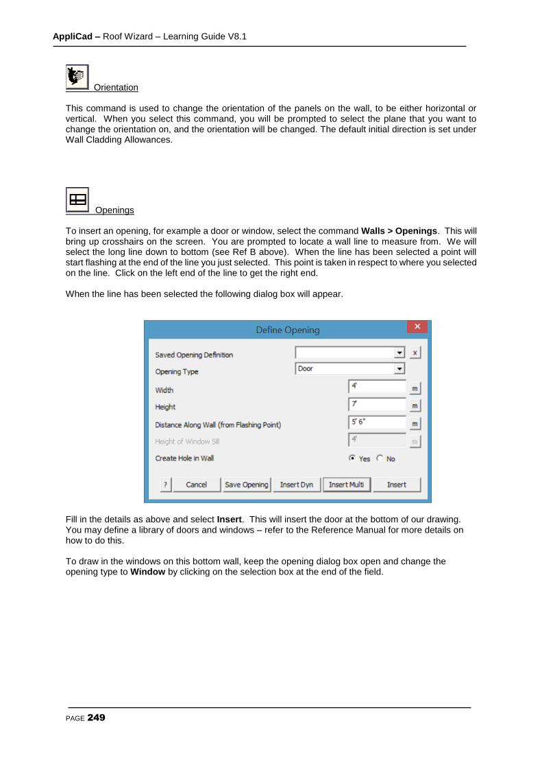
AppliCad – Roof Wizard – Learning Guide V8.1
PAGE 249
Orientation This command is used to change the orientation of the panels on the wall, to be either horizontal or vertical. When you select this command, you will be prompted to select the plane that you want to change the orientation on, and the orientation will be changed. The default initial direction is set under Wall Cladding Allowances.
Openings To insert an opening, for example a door or window, select the command Walls > Openings. This will bring up crosshairs on the screen. You are prompted to locate a wall line to measure from. We will select the long line down to bottom (see Ref B above). When the line has been selected a point will start flashing at the end of the line you just selected. This point is taken in respect to where you selected on the line. Click on the left end of the line to get the right end. When the line has been selected the following dialog box will appear.
Fill in the details as above and select Insert. This will insert the door at the bottom of our drawing. You may define a library of doors and windows – refer to the Reference Manual for more details on how to do this. To draw in the windows on this bottom wall, keep the opening dialog box open and change the opening type to Window by clicking on the selection box at the end of the field.

AppliCad – Roof Wizard – Learning Guide V8.1
PAGE 250
Fill in the details as above and click Insert. This will now insert the first of the three windows on the bottom wall. Keeping the Height of window sill, Width of window and Height of window, fields the same. Change the Distance along the wall to 2’, and select Insert. This will insert the second window along the bottom wall. Finally change the Distance field again to 7' and again click Insert, Followed by Finish as you have finished inserting openings along this wall. Click your right mouse button once to cancel out of this command. To insert the long window along the right hand wall, select Walls > Openings again, and select the right hand side wall that the window is on. Make sure you select near the end where the long wall connects. From here fill in the fields as shown. With the fields filled in select Insert, to insert the window and then Finish. Then Right Click the mouse. You should now be presented with a view looking something like the following;
This completes the insertion of all of our openings in our wall outline.
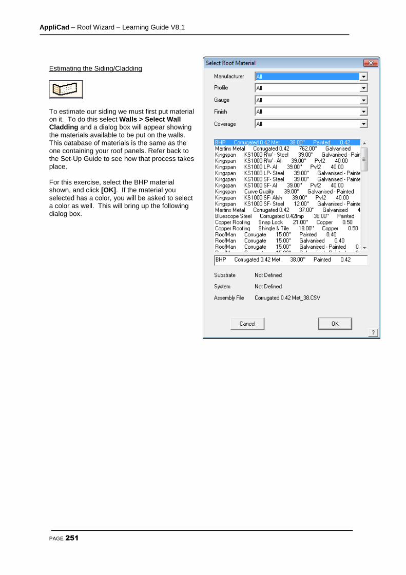
AppliCad – Roof Wizard – Learning Guide V8.1
PAGE 251
Estimating the Siding/Cladding
To estimate our siding we must first put material on it. To do this select Walls > Select Wall Cladding and a dialog box will appear showing the materials available to be put on the walls. This database of materials is the same as the one containing your roof panels. Refer back to the Set-Up Guide to see how that process takes place. For this exercise, select the BHP material shown, and click [OK]. If the material you selected has a color, you will be asked to select a color as well. This will bring up the following dialog box.

AppliCad – Roof Wizard – Learning Guide V8.1
PAGE 252
If you want to add fasteners and/or clips to the material that you are using, click on the selection box at the end of the field, and select the required fasteners and/or clips. When this is done click [OK]. The next step is to estimate the siding. This is done by clicking on the Generate command. This will generate the sheets on our wall, using the specifications of the material we previously specified. If you wish to nominate an Identifying Name to each wall plane, you can use the Set-Identifier command. You will be asked be firstly locate a Wall Panel you wish to identify, and then you will be asked to give each wall plane a name. This name will appear on any reports that are generated later. Right click with your mouse when you have finished.
When this is done, click on the Walls > Apply Wall Materials > Create Panel Cut List command and all of the sheets are tallied up and put into a cutting list, similar to the following.
Note: You define your labour rate for applying the walls within Set-Up > Set up Pay Rates > Wall cladding pay rates. If you have not already defined a new labour rate, this section will not appear. In time you will define a number of different labour rates for applying your different materials and it is at this point that you select which labour rate you will use for this job. Notice also that an allowance file may be selected here.
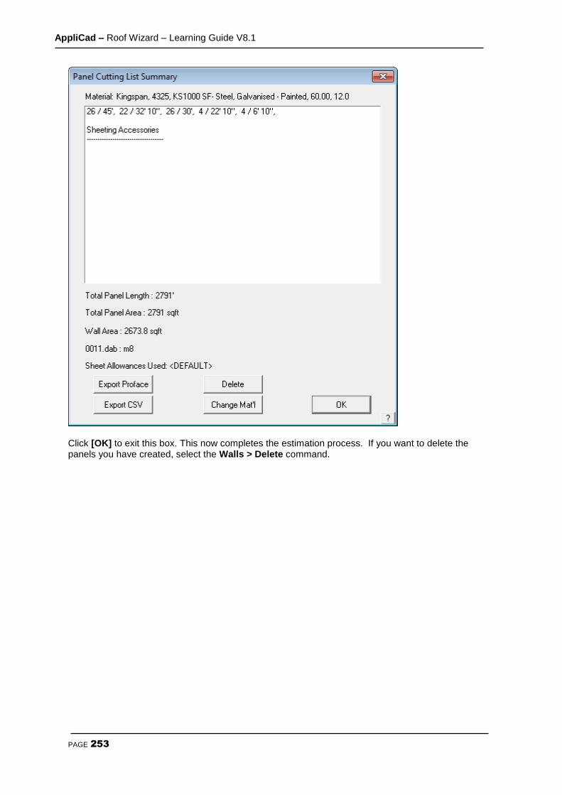
AppliCad – Roof Wizard – Learning Guide V8.1
PAGE 253
Click [OK] to exit this box. This now completes the estimation process. If you want to delete the panels you have created, select the Walls > Delete command.
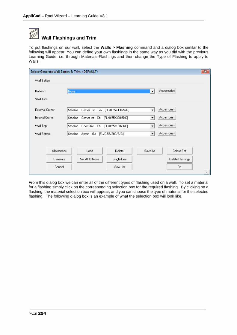
AppliCad – Roof Wizard – Learning Guide V8.1
PAGE 254
Wall Flashings and Trim To put flashings on our wall, select the Walls > Flashing command and a dialog box similar to the following will appear. You can define your own flashings in the same way as you did with the previous Learning Guide, i.e. through Materials-Flashings and then change the Type of Flashing to apply to Walls.
From this dialog box we can enter all of the different types of flashing used on a wall. To set a material for a flashing simply click on the corresponding selection box for the required flashing. By clicking on a flashing, the material selection box will appear, and you can choose the type of material for the selected flashing. The following dialog box is an example of what the selection box will look like.
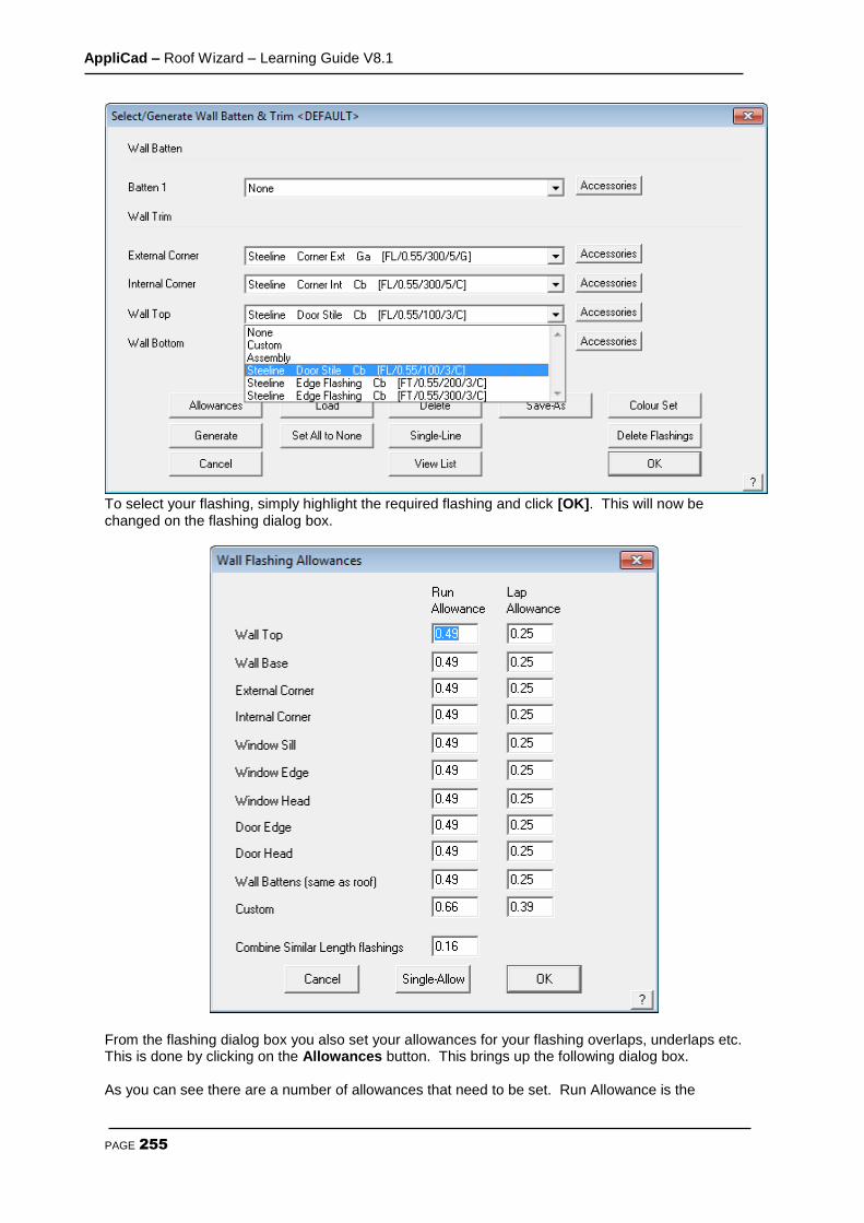
AppliCad – Roof Wizard – Learning Guide V8.1
PAGE 255
To select your flashing, simply highlight the required flashing and click [OK]. This will now be changed on the flashing dialog box.
From the flashing dialog box you also set your allowances for your flashing overlaps, underlaps etc. This is done by clicking on the Allowances button. This brings up the following dialog box. As you can see there are a number of allowances that need to be set. Run Allowance is the

AppliCad – Roof Wizard – Learning Guide V8.1
PAGE 256
allowance for the end of a run (end corners). Lap Allowance is the allowance for overlapping before the end of a run. Single-Allow allows you to set a different allowance for a single run. When your allowances are set click [OK] , and you will return to the flashings dialog box. From here you can now generate your cutting list for your flashings. This is done by clicking on Generate. Your flashings will now be generated using what you specified earlier. When the process is done a dialog box similar to the following will appear.
From here you can see all the flashing that is required for this job. Click [Continue] to exit and the Flashings dialog box will appear again. If you wish to see this list again, click on the View-List command in the Flashings dialog box. If you wish to delete the flashings for the job click Delete and they will be deleted. If you wish to add a flashing to a particular line, use the Single-Line command. To exit the flashings dialog box, click [OK].
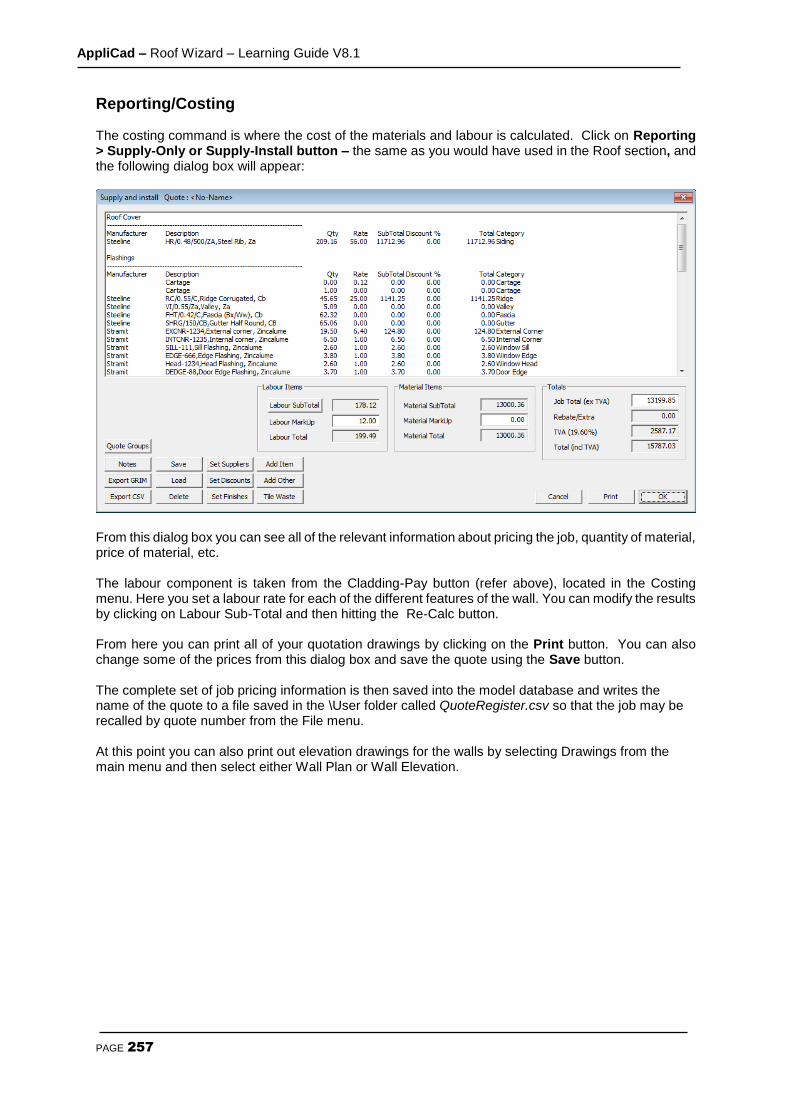
AppliCad – Roof Wizard – Learning Guide V8.1
PAGE 257
Reporting/Costing The costing command is where the cost of the materials and labour is calculated. Click on Reporting > Supply-Only or Supply-Install button – the same as you would have used in the Roof section, and the following dialog box will appear:
From this dialog box you can see all of the relevant information about pricing the job, quantity of material, price of material, etc. The labour component is taken from the Cladding-Pay button (refer above), located in the Costing menu. Here you set a labour rate for each of the different features of the wall. You can modify the results by clicking on Labour Sub-Total and then hitting the Re-Calc button. From here you can print all of your quotation drawings by clicking on the Print button. You can also change some of the prices from this dialog box and save the quote using the Save button. The complete set of job pricing information is then saved into the model database and writes the name of the quote to a file saved in the \User folder called QuoteRegister.csv so that the job may be recalled by quote number from the File menu. At this point you can also print out elevation drawings for the walls by selecting Drawings from the main menu and then select either Wall Plan or Wall Elevation.