Embed Size (px)
Citation preview
Copyright © 2018, 2020 MiTek®. All rights reserved.Patented. See Legal Notice for list of patents. Manual applies to United States equipment.
CAUTIONMiTek recommends printing this manual in high resolution using color ink. Many of the graphics may be unclear and may create an unsafe condition if this recommendation is not followed.
001090 rev. C
Equipment Manual
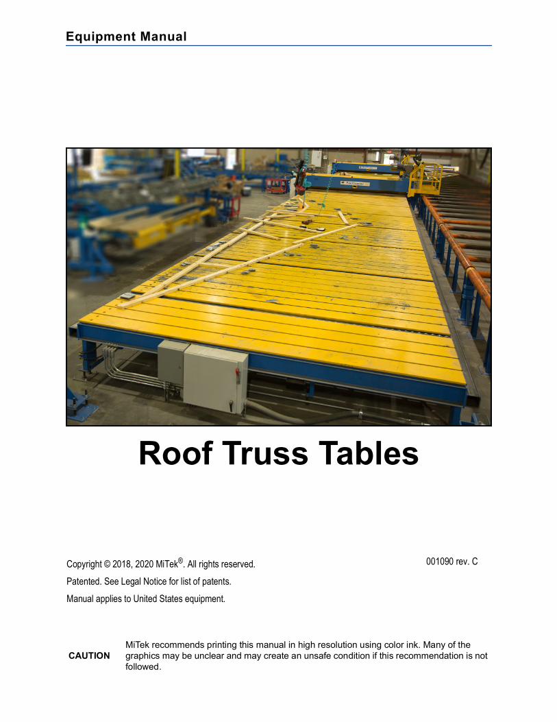
Roof Truss Tables
MiTek Machinery Division301 Fountain Lakes Industrial DriveSt. Charles, MO 63301Phone: 800-523-3380Fax: 636-328-9218www.mitek-us.com
Equipment Manual
Roof Truss Tables
Part # and Rev. 001090 rev. CPrint Date 21 May 2021Effectivity 31580-xxx
31595-xxx31610-xxx
Revision Date 21 May 2021Revised By A. McIntireOrig. Release Date 1 April 2007Created By R. Widder
Original Instructions: 001090 rev. C ii
Legal Notice
PatentsMade and sold under one or more of the following patents:
Return Goods PolicyReturn goods cannot be accepted without prior authorization and are subject to a restocking charge. The Seller certifies the articles specified herein were produced in compliance with all provisions of the Fair Labor Standards Act of 1938, as amended, including Section 12.—Rev. 6/98.
Corrections and ImprovementsTo report errors or recommend improvements to this manual, please complete the Document Evaluation Form in the appendices. Mail or fax the form to:
MiTek Machinery Division301 Fountain Lakes Industrial DriveSt. Charles, MO 63301Attn: Engineering Manager, Fax: 636-328-9218
U.S. 4,986,052 U.S. 5,837,014 U.S. 6,219,975U.S. 5,385,339 U.S. 5,854,747 U.S. 6,260,263U.S. 5,493,834 U.S. 5,873,567 U.S. 6,317,980U.S. 5,568,862, U.S. 5,884,448 U.S. 6,389,762U.S. 5,630,697 U.S. 5,885,731 U.S. 6,401,422U.S. 5,636,494 U.S. 5,906,264 U.S. 6,412,246U.S. 5,638,658 U.S. 5,934,866 U.S. 6,418,601U.S. 5,640,832 U.S. 5,947,460 U.S. 6,539,615U.S. 5,655,399 U.S. 5,987,828 U.S. 6,666,367U.S. 5,678,395 U.S. 5,996,303 U.S. 6,702,269U.S. 5,702,095 U.S. 6,048,165 U.S. 6,758,022U.S. 5,707,204 U.S. 6,112,968 U.S. 6,817,392U.S. 5,735,087 U.S. 6,134,775 U.S. 6,834,470U.S. 5,810,341 U.S. 6,170,688 U.S. 6,907,820U.S. 5,819,412 U.S. 6,205,637 Other patents may applyU.S. 5,833,222 U.S. 6,212,849

Original Instructions: 001090 rev. C iii
Notice of ChangeRoof Gantry TablesUse this page to record service bulletins and notices that you receive to keep your manual updated.
Number Date Title
Original Instructions: 001090 rev. C iv
Table of Contents
Legal Notice iiPatents . . . . . . . . . . . . . . . . . . . . . . . . . . . . . . . . . . . . . . . . . . . . . . . . . . . . . . . . . . . iiReturn Goods Policy . . . . . . . . . . . . . . . . . . . . . . . . . . . . . . . . . . . . . . . . . . . . . . . . iiCorrections and Improvements . . . . . . . . . . . . . . . . . . . . . . . . . . . . . . . . . . . . . . . ii
Notice of Change iiiSafety (English) vii
Safety Indicator Signal Words . . . . . . . . . . . . . . . . . . . . . . . . . . . . . . . . . . . . . . . viiSafety Requirements . . . . . . . . . . . . . . . . . . . . . . . . . . . . . . . . . . . . . . . . . . . . . . . viii
General Equipment Safety Rules . . . . . . . . . . . . . . . . . . . . . . . . . . . . . . . . . . . viiiLockout/Tagout . . . . . . . . . . . . . . . . . . . . . . . . . . . . . . . . . . . . . . . . . . . . . . . . . . xiTroubleshooting with an Energized Machine. . . . . . . . . . . . . . . . . . . . . . . . . . . xiv
Safety Tests . . . . . . . . . . . . . . . . . . . . . . . . . . . . . . . . . . . . . . . . . . . . . . . . . . . . . . xvRestricted Zone . . . . . . . . . . . . . . . . . . . . . . . . . . . . . . . . . . . . . . . . . . . . . . . . . . . xviSafety Symbol Definitions. . . . . . . . . . . . . . . . . . . . . . . . . . . . . . . . . . . . . . . . . . xviiDeclaration of Safety Conformity . . . . . . . . . . . . . . . . . . . . . . . . . . . . . . . . . . . . . xxi
Seguridad (Español) xxiiIndicadores de seguridad: Palabras de aviso . . . . . . . . . . . . . . . . . . . . . . . . . . xxiiRequerimientos de seguridad. . . . . . . . . . . . . . . . . . . . . . . . . . . . . . . . . . . . . . . xxiii
Reglas general de seguridad para el equipo. . . . . . . . . . . . . . . . . . . . . . . . . . xxiiiBloqueo/Etiquetado . . . . . . . . . . . . . . . . . . . . . . . . . . . . . . . . . . . . . . . . . . . . . xxviiSolución de problemas con una máquina energizada. . . . . . . . . . . . . . . . . . . xxx
Prueba de seguridad . . . . . . . . . . . . . . . . . . . . . . . . . . . . . . . . . . . . . . . . . . . . . . xxxiZona Restringida . . . . . . . . . . . . . . . . . . . . . . . . . . . . . . . . . . . . . . . . . . . . . . . . xxxiiInformación adicional . . . . . . . . . . . . . . . . . . . . . . . . . . . . . . . . . . . . . . . . . . . . xxxii
Introduction 1Introduction to the Manual . . . . . . . . . . . . . . . . . . . . . . . . . . . . . . . . . . . . . . . . . . . 1
Purpose of This Manual. . . . . . . . . . . . . . . . . . . . . . . . . . . . . . . . . . . . . . . . . . . . 1Scope of This Manual . . . . . . . . . . . . . . . . . . . . . . . . . . . . . . . . . . . . . . . . . . . . . 2The Drawing Set . . . . . . . . . . . . . . . . . . . . . . . . . . . . . . . . . . . . . . . . . . . . . . . . . 2
Additional Resources . . . . . . . . . . . . . . . . . . . . . . . . . . . . . . . . . . . . . . . . . . . . . . . 4Website . . . . . . . . . . . . . . . . . . . . . . . . . . . . . . . . . . . . . . . . . . . . . . . . . . . . . . . . 4Phone or E-mail Support . . . . . . . . . . . . . . . . . . . . . . . . . . . . . . . . . . . . . . . . . . . 4Contact Information . . . . . . . . . . . . . . . . . . . . . . . . . . . . . . . . . . . . . . . . . . . . . . . 4
General Information 5Introduction to the Equipment . . . . . . . . . . . . . . . . . . . . . . . . . . . . . . . . . . . . . . . . 5
Purpose of the Equipment . . . . . . . . . . . . . . . . . . . . . . . . . . . . . . . . . . . . . . . . . . 5Description of the Equipment . . . . . . . . . . . . . . . . . . . . . . . . . . . . . . . . . . . . . . . 5Safety Compliance of the Equipment . . . . . . . . . . . . . . . . . . . . . . . . . . . . . . . . . 5
Components Overview . . . . . . . . . . . . . . . . . . . . . . . . . . . . . . . . . . . . . . . . . . . . . . 7Technical Specifications . . . . . . . . . . . . . . . . . . . . . . . . . . . . . . . . . . . . . . . . . . . . . 7
Installation 8Installation Requirements . . . . . . . . . . . . . . . . . . . . . . . . . . . . . . . . . . . . . . . . . . . . 8
Environmental Requirements . . . . . . . . . . . . . . . . . . . . . . . . . . . . . . . . . . . . . . . 8Infrastructure Requirements . . . . . . . . . . . . . . . . . . . . . . . . . . . . . . . . . . . . . . . . 8
Table of Contents
Original Instructions: 001090 rev. C v
Responsibilities During Installation . . . . . . . . . . . . . . . . . . . . . . . . . . . . . . . . . . . 10Responsibilities Before Moving or Selling . . . . . . . . . . . . . . . . . . . . . . . . . . . . . 10Marking Restricted Zone . . . . . . . . . . . . . . . . . . . . . . . . . . . . . . . . . . . . . . . . . . . . 10
Marking Area on Your Own . . . . . . . . . . . . . . . . . . . . . . . . . . . . . . . . . . . . . . . . 10Installing MiTek Restricted Zone Tape . . . . . . . . . . . . . . . . . . . . . . . . . . . . . . . 10
Local Codes and Regulations. . . . . . . . . . . . . . . . . . . . . . . . . . . . . . . . . . . . . . . . 11
Operation 12Before You Begin . . . . . . . . . . . . . . . . . . . . . . . . . . . . . . . . . . . . . . . . . . . . . . . . . . 12Operator Controls . . . . . . . . . . . . . . . . . . . . . . . . . . . . . . . . . . . . . . . . . . . . . . . . . 13
Stopping the Machine . . . . . . . . . . . . . . . . . . . . . . . . . . . . . . . . . . . . . . . . . . . . 13Understanding the Table Components . . . . . . . . . . . . . . . . . . . . . . . . . . . . . . . 13Control Valves . . . . . . . . . . . . . . . . . . . . . . . . . . . . . . . . . . . . . . . . . . . . . . . . . . 13
Operating Procedure . . . . . . . . . . . . . . . . . . . . . . . . . . . . . . . . . . . . . . . . . . . . . . . 15Operating the Tables . . . . . . . . . . . . . . . . . . . . . . . . . . . . . . . . . . . . . . . . . . . . . 15Operating the Pneumatic Ejection System . . . . . . . . . . . . . . . . . . . . . . . . . . . . 15
Maintenance 17Performing Maintenance Safely . . . . . . . . . . . . . . . . . . . . . . . . . . . . . . . . . . . . . . 17
Before Operating This Machine. . . . . . . . . . . . . . . . . . . . . . . . . . . . . . . . . . . . . 17Lockout/Tagout . . . . . . . . . . . . . . . . . . . . . . . . . . . . . . . . . . . . . . . . . . . . . . . . . 18Important Safety Information . . . . . . . . . . . . . . . . . . . . . . . . . . . . . . . . . . . . . . . 18Making Adjustments and Replacing Parts . . . . . . . . . . . . . . . . . . . . . . . . . . . . . 20Wearing Personal Protective Equipment. . . . . . . . . . . . . . . . . . . . . . . . . . . . . . 21Testing the Safety of the Machine . . . . . . . . . . . . . . . . . . . . . . . . . . . . . . . . . . . 21
Cleaning and Inspecting . . . . . . . . . . . . . . . . . . . . . . . . . . . . . . . . . . . . . . . . . . . . 21Cleaning . . . . . . . . . . . . . . . . . . . . . . . . . . . . . . . . . . . . . . . . . . . . . . . . . . . . . . 21Inspecting the Ejectors . . . . . . . . . . . . . . . . . . . . . . . . . . . . . . . . . . . . . . . . . . . 22Inspecting the Ejection System as a Whole . . . . . . . . . . . . . . . . . . . . . . . . . . . 22
Pneumatic System Maintenance . . . . . . . . . . . . . . . . . . . . . . . . . . . . . . . . . . . . . 22Removing Pressure from the Pneumatic System . . . . . . . . . . . . . . . . . . . . . . . 22Filter/Regulator . . . . . . . . . . . . . . . . . . . . . . . . . . . . . . . . . . . . . . . . . . . . . . . . . 23Setup Valve . . . . . . . . . . . . . . . . . . . . . . . . . . . . . . . . . . . . . . . . . . . . . . . . . . . . 24Control Valves . . . . . . . . . . . . . . . . . . . . . . . . . . . . . . . . . . . . . . . . . . . . . . . . . . 25Ejector Cylinders . . . . . . . . . . . . . . . . . . . . . . . . . . . . . . . . . . . . . . . . . . . . . . . . 26High Slope Ejector Bumpers . . . . . . . . . . . . . . . . . . . . . . . . . . . . . . . . . . . . . . . 27
Troubleshooting 29Safety Notes for Troubleshooting . . . . . . . . . . . . . . . . . . . . . . . . . . . . . . . . . . . . 29
General Troubleshooting Safety Tips . . . . . . . . . . . . . . . . . . . . . . . . . . . . . . . . 29Electrical Troubleshooting Safety Tips . . . . . . . . . . . . . . . . . . . . . . . . . . . . . . . 30
Getting Started with Troubleshooting . . . . . . . . . . . . . . . . . . . . . . . . . . . . . . . . . 31Tools Required . . . . . . . . . . . . . . . . . . . . . . . . . . . . . . . . . . . . . . . . . . . . . . . . . 31First Steps . . . . . . . . . . . . . . . . . . . . . . . . . . . . . . . . . . . . . . . . . . . . . . . . . . . . . 32
Problems and Solutions . . . . . . . . . . . . . . . . . . . . . . . . . . . . . . . . . . . . . . . . . . . . 33
Parts List 34Ordering Parts . . . . . . . . . . . . . . . . . . . . . . . . . . . . . . . . . . . . . . . . . . . . . . . . . . . . 34Stocking Spare Parts . . . . . . . . . . . . . . . . . . . . . . . . . . . . . . . . . . . . . . . . . . . . . . . 34Safety Notes for Replacement Parts . . . . . . . . . . . . . . . . . . . . . . . . . . . . . . . . . . 34
List of Parts to Keep in Stock . . . . . . . . . . . . . . . . . . . . . . . . . . . . . . . . . . . . . . 35
Maintenance Checklist 36Using the Maintenance Checklists . . . . . . . . . . . . . . . . . . . . . . . . . . . . . . . . . . . . 36Safety Notes for the Maintenance Checklists . . . . . . . . . . . . . . . . . . . . . . . . . . . 36Checklist . . . . . . . . . . . . . . . . . . . . . . . . . . . . . . . . . . . . . . . . . . . . . . . . . . . . . . . . . 37
Table of Contents
Original Instructions: 001090 rev. C vi
Drawing Set 38Document Evaluation 39
Document Evaluation Form . . . . . . . . . . . . . . . . . . . . . . . . . . . . . . . . . . . . . . . . . 40General Evaluation . . . . . . . . . . . . . . . . . . . . . . . . . . . . . . . . . . . . . . . . . . . . . . 40Specific Evaluation . . . . . . . . . . . . . . . . . . . . . . . . . . . . . . . . . . . . . . . . . . . . . . 40
Glossary 41Index 45

Original Instructions: 001090 rev. C vii
Safety (English)
Safety Indicator Signal WordsThe following signal words and colors are used throughout this document to indicate safety hazards. Pay careful attention when you see them. The level of severity differs for each signal word and color.
Signal words are accompanied by graphics showing what personnel should or should not do. The graphics are called safety symbols and are defined on page xvii, but more specific text is provided every time a graphic is used throughout the manual. Everyone near the machine must be trained on how to read these safety indicators.
Failure to comply with the instructions accompanying each signal word may result in property damage, personal injury, or even death. Personnel must follow all safety procedures and practices to ensure the safest possible operation of this equipment. However, at no time is this document a substitute for common sense. Personnel must ensure that the work environment is safe and free of distractions.
Purpose of Chapter
This chapter explains general information and specific procedures for operating the machine safety.
dangerIndicates an imminently hazardous situation which, if not avoided, is likely to result in death or serious injury.warningIndicates a potentially hazardous situation, which, if not avoided, may result in death or serious injury.cautionIndicates a potentially hazardous situation which, if not avoided, may result in minor or moderate injury.noticeCalls attention to information that is significant to understanding the operation at hand or the potential for property damage.environmentalApplies to conditions that may affect the environment but do not have an immediate, direct effect on personnel or equipment.
Refiérase a la pagina xxii para español.For safety information in Spanish, refer to page xxii
Safety
Original Instructions: 001090 rev. C viii
Safety RequirementsBecause it is impossible to anticipate every circumstance that might involve a hazard, the safety information provided in this equipment manual and on the machine is not all-inclusive. If this machine is operated or serviced using a procedure not specifically recommended by the manufacturer, the procedure shall be approved by a professional engineer to ensure it will not render the equipment unsafe. Use extreme caution and common sense at all times.
General Equipment Safety Rules
Know Your Equipment
• Read this manual completely before using or maintaining the equipment. Do not operate this machine unless you have a thorough knowledge of the controls, safety devices, emergency stops, and operating procedures outlined in this manual.
• Read and follow all safety notes. Failure to comply with these instructions may result in economic loss, property damage, and/or personal injury including death.
• Refer to the lockout/tagout guidelines on the following pages to safely perform maintenance and troubleshooting of this equipment.
• Observe and obey all safety labels. Replace worn labels immediately.
• Use this equipment solely for the purpose described in this manual.
• MiTek equipment is designed to work with optional accessories and other MiTek machines. When applicable, refer to the appropriate equipment manual for specific safety information.
• Only qualified personnel should attempt to operate or perform maintenance on this equipment. “Qualified personnel” is defined as: ...a person or persons who, by possession of a recognized degree or certificate of professional training, or who, by extensive knowledge, training, or experience, has successfully demonstrated the ability to solve problems relating to the subject matter and work—ANSI B30.2-1983...one who has skills and knowledge related to the construction and operation of the electrical equipment and installations and has received safety training on the hazards involved—NEC 2002 Handbook
Personal Safety
• Always wear safety glasses and hearing protection in an industrial environment.• Utilize a filtering face piece (dust mask) when working near sawdust.• Wear proper clothing and appropriate personal protective equipment (e.g., safety
glasses and hearing protection.) Do not wear loose clothing or jewelry. Confine long hair by tying it back.
• Use caution when lifting heavy parts or material.• Pay attention to your surroundings.
Safety
Original Instructions: 001090 rev. C ix
Installing the Equipment
• Follow installation instructions completely.
• This equipment is not for use in a residential area.
Lockout/Tagout
• Before performing maintenance on the pneumatic or hydraulic systems, bleed the lines to eliminate pressure. Refer to Removing Pressure from the Pneumatic System.
• Lockout/tagout all energized systems before performing maintenance on them. Refer to lockout/tagout guidelines in on page xi.
Keeping a Safe Environment
• Keep children away. All visitors should be kept a safe distance from the work area. Hazards may not be apparent to individuals unfamiliar with the machine.
• Keep work areas well lit.
• Keep the work area clean and free of any trip or slip hazards.
• Do not use the equipment in damp or wet locations, or expose it to rain or snow.
• Minimize dust clouds and protect your equipment by cleaning dust in this manner:
a) Vacuum dust prior to blowing with air
b) Shut down electrical power and sources of ignition
c) If using compressed air, it should be a low compression (no more than 15 psi)
d) Powered cleaning equipment such as vacuums must be consistent with local governmental codes for use in dusty conditions.
Operating and Maintaining the Equipment
• Ensure that all people, tools, and foreign objects are clear of the restricted zones before operating this equipment. The restricted zones are shown on page xvi.
• Perform safety tests to ensure all E-stops are working properly before operating the equipment at the initial startup, after performing any maintenance, and in accordance with the maintenance schedule.
• In case of machine malfunction, stop the machine immediately using an E-stop and report the malfunction to a supervisor.
• Never leave the machine running unattended. Turn the power off! Do not leave the machine until all parts have come to a complete stop and all electrical power has been shut off.
• Check for worn or damaged parts regularly. Repair or replace them immediately.
• Keep the hydraulic, pneumatic, and electrical systems in good working order at all times. Repair leaks and loose connections immediately. Never exceed the recommended pressure or electrical power.
Safety
Original Instructions: 001090 rev. C x
• Check that all safety devices are in working order before each shift starts. All protective guards and safety devices must be in place before and during use of the machine. Never disconnect or bypass any safety device or electrical interlock.
• Only qualified maintenance personnel shall remove or install safety devices.
• Periodically inspect the quality of the finished product.
Electrical Safety
• Do not use any liquids in the interior of electrical cabinets.
• When using solvents on and around the machine, remove power to the machine to eliminate the chance of sparking, resulting in explosion or fire. Wear a respirator approved for use with solvents. Wear protective clothing, gloves, and safety glasses.
Safety
Original Instructions: 001090 rev. C xi
Lockout/Tagout
Lockout/Tagout Guidelines
All lockout/tagout guidelines must be met according to OSHA 29 CFR 1910.147. A specific procedure should be included in your company’s energy control program. This manual is not intended to replace your company’s de-energizing or lockout/tagout procedure required by OSHA, but merely to provide general guidance.
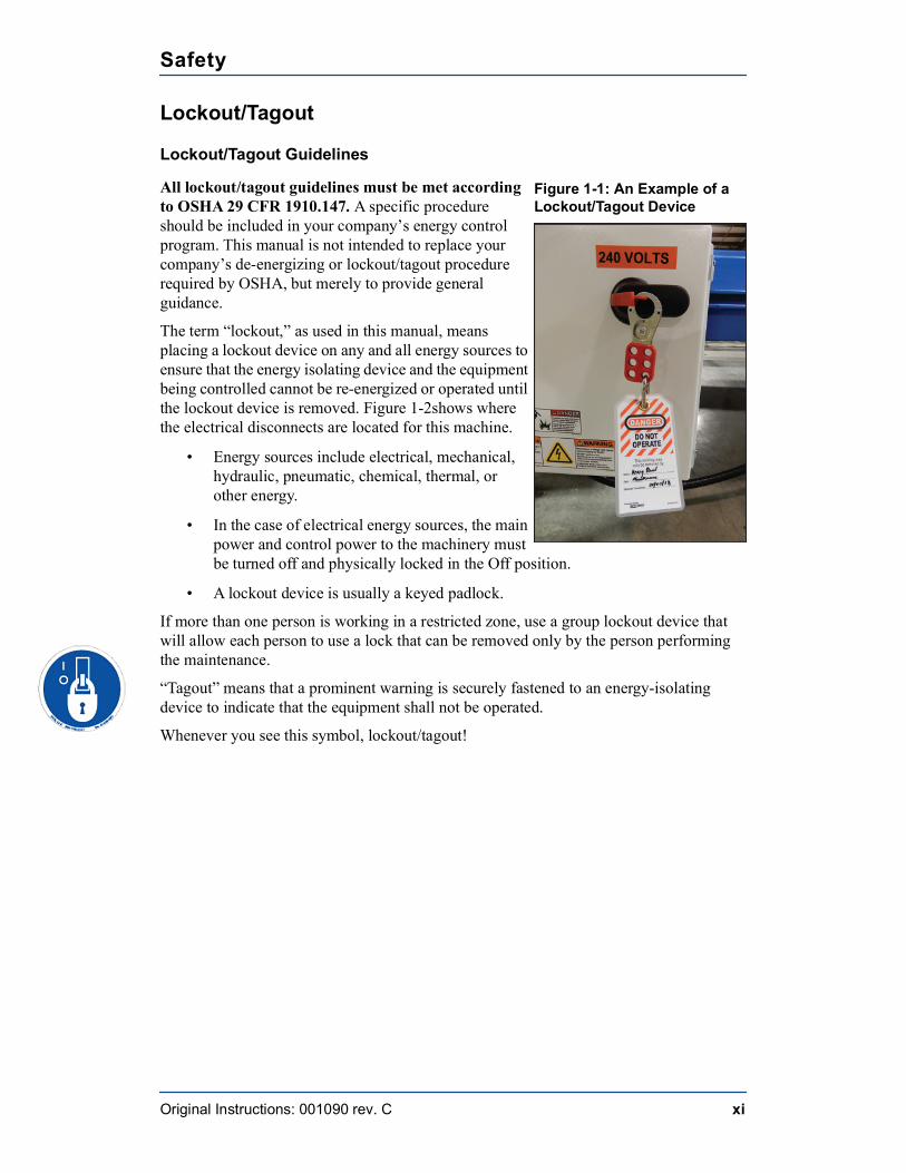
The term “lockout,” as used in this manual, means placing a lockout device on any and all energy sources to ensure that the energy isolating device and the equipment being controlled cannot be re-energized or operated until the lockout device is removed. Figure 1-2shows where the electrical disconnects are located for this machine.
• Energy sources include electrical, mechanical, hydraulic, pneumatic, chemical, thermal, or other energy.
• In the case of electrical energy sources, the main power and control power to the machinery must be turned off and physically locked in the Off position.
• A lockout device is usually a keyed padlock.
If more than one person is working in a restricted zone, use a group lockout device that will allow each person to use a lock that can be removed only by the person performing the maintenance.
“Tagout” means that a prominent warning is securely fastened to an energy-isolating device to indicate that the equipment shall not be operated.
Whenever you see this symbol, lockout/tagout!
Figure 1-1: An Example of a Lockout/Tagout Device
Safety
Original Instructions: 001090 rev. C xii
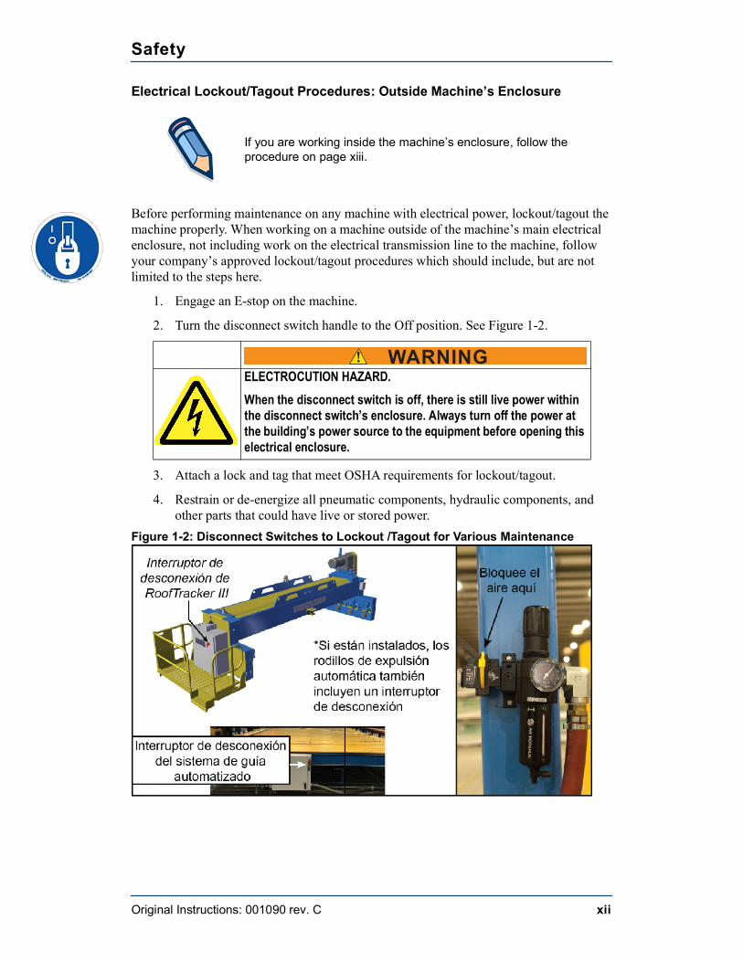
Electrical Lockout/Tagout Procedures: Outside Machine’s Enclosure
Before performing maintenance on any machine with electrical power, lockout/tagout the machine properly. When working on a machine outside of the machine’s main electrical enclosure, not including work on the electrical transmission line to the machine, follow your company’s approved lockout/tagout procedures which should include, but are not limited to the steps here.
1. Engage an E-stop on the machine.
2. Turn the disconnect switch handle to the Off position. See Figure 1-2.
3. Attach a lock and tag that meet OSHA requirements for lockout/tagout.
4. Restrain or de-energize all pneumatic components, hydraulic components, and other parts that could have live or stored power.
Figure 1-2: Disconnect Switches to Lockout /Tagout for Various Maintenance
If you are working inside the machine’s enclosure, follow the procedure on page xiii.
! WARNINGELECTROCUTION HAZARD.When the disconnect switch is off, there is still live power within the disconnect switch’s enclosure. Always turn off the power at the building’s power source to the equipment before opening this electrical enclosure.
Safety
Original Instructions: 001090 rev. C xiii
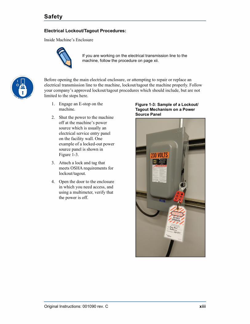
Electrical Lockout/Tagout Procedures:
Inside Machine’s Enclosure
Before opening the main electrical enclosure, or attempting to repair or replace an electrical transmission line to the machine, lockout/tagout the machine properly. Follow your company’s approved lockout/tagout procedures which should include, but are not limited to the steps here.
1. Engage an E-stop on the machine.
2. Shut the power to the machine off at the machine’s power source which is usually an electrical service entry panel on the facility wall. One example of a locked-out power source panel is shown in Figure 1-3.
3. Attach a lock and tag that meets OSHA requirements for lockout/tagout.
4. Open the door to the enclosure in which you need access, and using a multimeter, verify that the power is off.
If you are working on the electrical transmission line to the machine, follow the procedure on page xii.
Figure 1-3: Sample of a Lockout/Tagout Mechanism on a Power Source Panel
Safety
Original Instructions: 001090 rev. C xiv
Pneumatic System Lockout/Tagout Procedure: WITH Lockout/Tagout
If working on components other than the pneumatic system, but that requires you to be near the vicinity of movable pneumatic components, you must, at a minimum, physically restrain the pneumatic components from moving. If this is not possible, lockout/tagout the entire pneumatic system.
Pneumatic System Lockout/Tagout Procedure: WITHOUT Lockout/Tagout
Before attempting repair or maintenance on a pneumatic line or component, lockout/ tagout the machine properly. Follow your company’s approved lockout/tagout procedures.
Troubleshooting with an Energized MachineOnly a qualified electrician, using the personal protective equipment and following the procedures recommended in NFPA 70E should ever attempt service or repair of or near an energized area or component of the machine.
Whenever maintenance is performed while the equipment is electrically energized, there is a potential electric arc flash hazard. Refer to NFPA 70E for the personal protective equipment required when working with electrically energized components. Pneumatic and hydraulic components may move unexpectedly if not de-energized. Physically restrain any components capable of movement when working on or near those components.
Safety
Original Instructions: 001090 rev. C xv
Safety TestsThis test procedure MUST be performed by qualified personnel at startup and after ANY maintenance, adjustment, or modification.
1. Ensure air pressure is set to 100 PSI. See Adjusting the Pressure.
2. Actuate each setup to test that the ejectors raise when expected and lower when expected at a reasonable speed.
Safety
Original Instructions: 001090 rev. C xvi
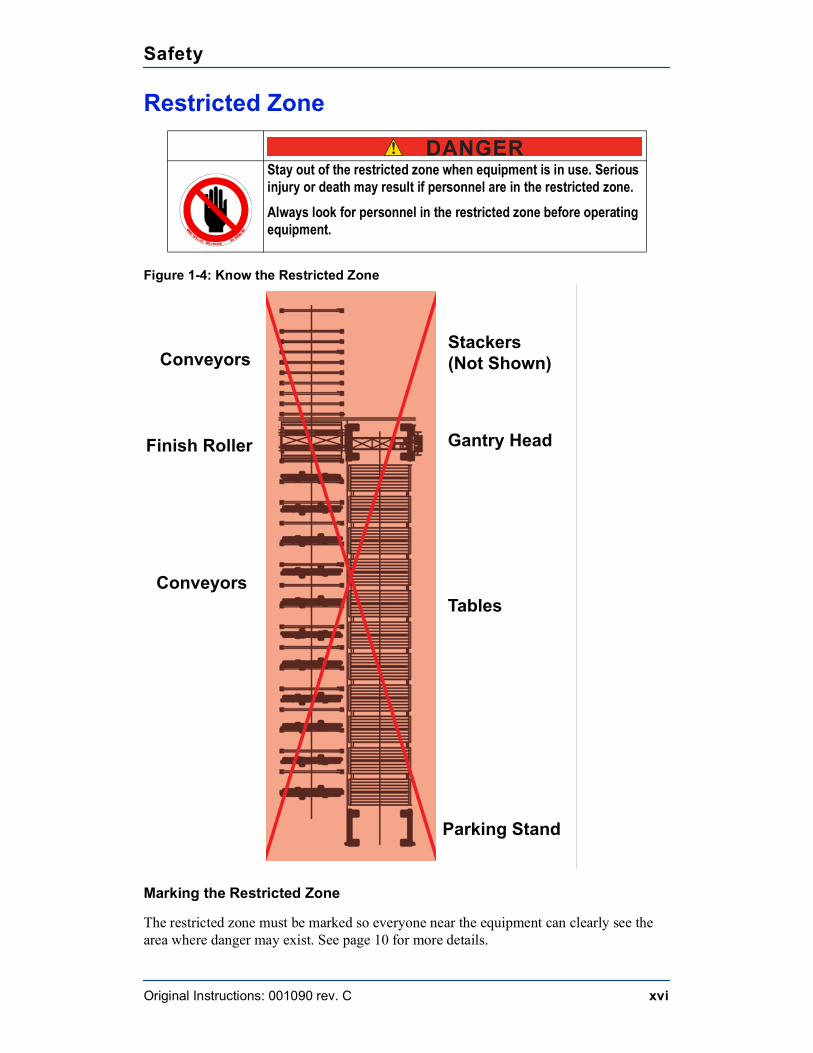
Restricted Zone
Figure 1-4: Know the Restricted Zone
Marking the Restricted Zone
The restricted zone must be marked so everyone near the equipment can clearly see the area where danger may exist. See page 10 for more details.
! DANGERStay out of the restricted zone when equipment is in use. Serious injury or death may result if personnel are in the restricted zone.Always look for personnel in the restricted zone before operating equipment.
Gantry Head
Tables
Parking Stand
Conveyors
Finish Roller
ConveyorsStackers (Not Shown)
Safety
Original Instructions: 001090 rev. C xvii
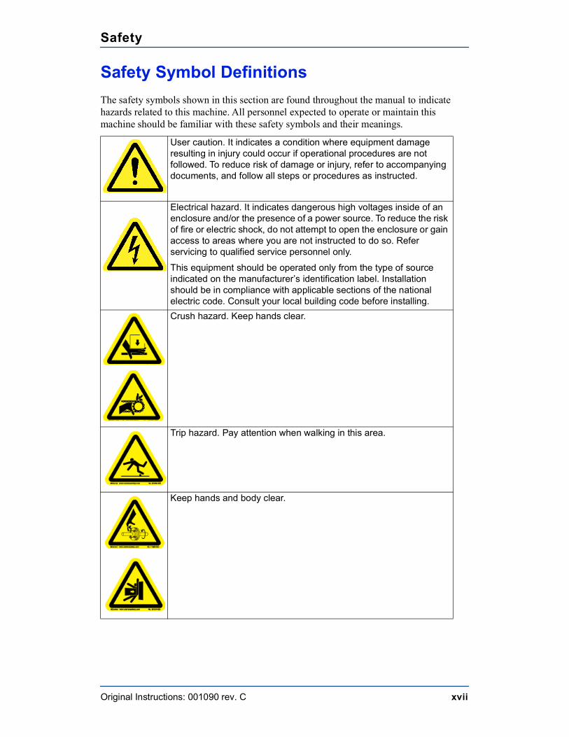
Safety Symbol DefinitionsThe safety symbols shown in this section are found throughout the manual to indicate hazards related to this machine. All personnel expected to operate or maintain this machine should be familiar with these safety symbols and their meanings.
User caution. It indicates a condition where equipment damage resulting in injury could occur if operational procedures are not followed. To reduce risk of damage or injury, refer to accompanying documents, and follow all steps or procedures as instructed.
Electrical hazard. It indicates dangerous high voltages inside of an enclosure and/or the presence of a power source. To reduce the risk of fire or electric shock, do not attempt to open the enclosure or gain access to areas where you are not instructed to do so. Refer servicing to qualified service personnel only.This equipment should be operated only from the type of source indicated on the manufacturer’s identification label. Installation should be in compliance with applicable sections of the national electric code. Consult your local building code before installing.
Crush hazard. Keep hands clear.
Trip hazard. Pay attention when walking in this area.
Keep hands and body clear.
Safety
Original Instructions: 001090 rev. C xviii
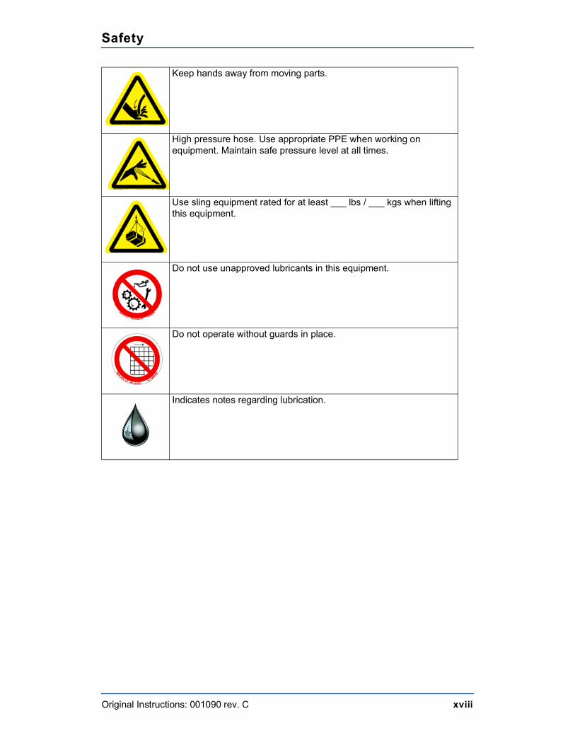
Keep hands away from moving parts.
High pressure hose. Use appropriate PPE when working on equipment. Maintain safe pressure level at all times.
Use sling equipment rated for at least ___ lbs / ___ kgs when lifting this equipment.
Do not use unapproved lubricants in this equipment.
Do not operate without guards in place.
Indicates notes regarding lubrication.
Safety
Original Instructions: 001090 rev. C xix
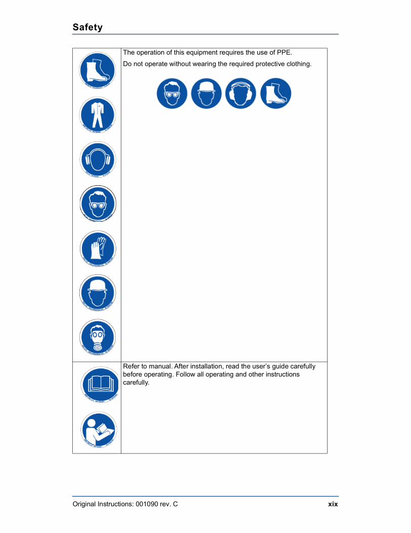
The operation of this equipment requires the use of PPE. Do not operate without wearing the required protective clothing.
Refer to manual. After installation, read the user’s guide carefully before operating. Follow all operating and other instructions carefully.
Safety
Original Instructions: 001090 rev. C xx
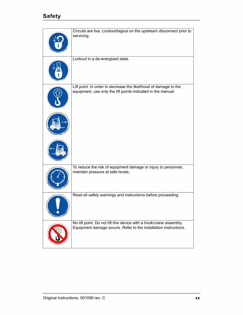
Circuits are live. Lockout/tagout on the upstream disconnect prior to servicing.
Lockout in a de-energized state.
Lift point. In order to decrease the likelihood of damage to the equipment, use only the lift points indicated in the manual.
To reduce the risk of equipment damage or injury to personnel, maintain pressure at safe levels.
Read all safety warnings and instructions before proceeding.
No lift point. Do not lift this device with a hook/crane assembly. Equipment damage occurs. Refer to the installation instructions.
Safety
Original Instructions: 001090 rev. C xxi
Declaration of Safety ConformityConforms electrically to the following:
• NFPA 79
• NEC Electrical Code
• Electrical enclosures carry UL 508A and the CUL for Canada
• Safety circuit conforms to Category 4 redundant monitoring
Conforms mechanically to the following:
• 10CFR 1910
• ANSI B 11.19
Original Instructions: 001090 rev. C xxii
Seguridad (Español)
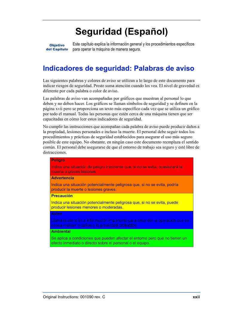
Indicadores de seguridad: Palabras de avisoLas siguientes palabras y colores de aviso se utilizan a lo largo de este documento para indicar riesgos de seguridad. Preste suma atención cuando los vea. El nivel de gravedad es diferente por cada palabra o color de aviso.
Las palabras de aviso van acompañadas por gráficos que muestran al personal lo que deben y no deben hacer. Los gráficos se llaman símbolos de seguridad y se definen en la página xvii pero se proporciona un texto más específico cada vez que se utiliza un gráfico por todo el manual. Todas las personas que estén cerca de una máquina tienen que ser capacitadas en cómo leer estos indicadores de seguridad.
No cumplir las instrucciones que acompañan cada palabra de aviso puede producir daños a la propiedad, lesiones personales e incluso la muerte. El personal debe seguir todos los procedimientos y prácticas de seguridad establecidos para asegurar el uso más seguro posible de este equipo. No obstante, en ningún caso este documento reemplaza el sentido común. El personal debe asegurarse de que el entorno de trabajo sea seguro y esté libre de distracciones.
Objetivodel Capítulo
Este capítulo explica la información general y los procedimientos específicos para operar la máquina de manera segura.
PeligroIndica una situación de peligro inminente que, si no se evita, ocasionará la muerte o graves lesiones.AdvertenciaIndica una situación potencialmente peligrosa que, si no se evita, podría producir la muerte o lesiones graves.PrecauciónIndica una situación potencialmente peligrosa que, si no se evita, puede producir lesiones menores o moderadas.AvisoLlama la atención a información importante para entender la operación que se desea realizar o daños a la propiedad probables.AmbientalSe aplica a condiciones que pueden afectar el entorno pero que no tienen un efecto inmediato o directo sobre el personal o el equipo.
Seguridad
Original Instructions: 001090 rev. C xxiii
Requerimientos de seguridadDebido a la imposibilidad de anticipar todas las circunstancias que podrían constituir un riesgo, la información de seguridad suministrada en este manual del equipo y sobre la máquina no es exhaustiva. Si se utiliza o realiza el mantenimiento de esta máquina utilizando un procedimiento no recomendado específicamente por el fabricante, el procedimiento deberá ser aprobado por un ingeniero profesional para asegurarse de que no afecte la seguridad del equipo. ¡Manéjese siempre con suma precaución y sentido común!
Reglas general de seguridad para el equipo
Conozca su equipo
• Lea este manual en su totalidad antes de utilizar o mantener el equipo. No utilice esta máquina a menos que esté perfectamente familiarizado con los controles, los dispositivos de seguridad, los frenos de emergencia y los procedimientos operativos que se describen en este manual.
• Lea y siga todas las notas de seguridad. El no cumplimiento de estas instrucciones podría producir pérdidas económicas, daños a la propiedad y/o lesiones personales, incluida la muerte.
• Refiérase a las pautas de bloqueo/etiquetado proporcionadas en las siguientes páginas para realizar el mantenimiento y solucionar problemas de este equipo en forma segura.
• Observe y cumpla con todas las etiquetas de seguridad. Cambie las etiquetas gastadas inmediatamente.
• Utilice este equipo únicamente para el propósito que se describe en este manual.
• El equipo MiTek está diseñado para funcionar con accesorios opcionales y otras máquinas MiTek. Cuando sea necesario, consulte el manual del equipo correspondiente para obtener información de seguridad específica.
• Sólo personal calificado debe intentar utilizar o realizar el mantenimiento de este equipo. Por "personal calificado" se entiende: ...una persona o personas que, por el hecho de poseer un título o certificado de capacitación profesional reconocido o que, por sus amplios conocimientos o experiencia, han demostrado con éxito estar capacitados para resolver problemas relacionados con el tema y el trabajo en cuestión—ANSI B30.2-1983...una persona que posee habilidades y conocimientos relacionados con la construcción y uso de equipos e instalaciones eléctricas y que ha recibido capacitación en seguridad sobre los riesgos posibles—NEC 2002 Handbook
Seguridad personal
• Use siempre lentes de seguridad y protección auditiva en un entorno industrial.
• Utilice una máscara protectora cuando trabaje cerca de aserrín.
Seguridad
Original Instructions: 001090 rev. C xxiv
• Utilice ropa adecuada y equipo de protección personal apropiado (por ejemplo, lentes de seguridad y protección auditiva.) No use ropa suelta ni joyas. Si tiene el cabello largo, áteselo para atrás.
• Proceda con precaución cuando levante piezas o materiales pesados.
Seguridad
Original Instructions: 001090 rev. C xxv
Instalació del equipo
• Siga las instrucciones de instalación al pie de la letra.
• No utilizar este equipo en zonas residenciales.
Bloqueo/Etiquetado
• Antes de realizar el mantenimiento de los sistemas neumáticos, purgue las líneas para eliminar la presión.
• Bloquee y etiquete todos los sistemas energizados antes de realizar tareas de mantenimiento en ellos. Refiérase a la sección Pautas de bloqueo/etiquetado en la página xxvii.
Cómo manterner un entorno seguro
• Mantenga alejados a los niños. Todos los visitantes deben mantenerse a una distancia segura del área de trabajo. Los riesgos pueden no ser evidentes a las personas no familiarizadas con la máquina.
• Mantenga las áreas de trabajo bien iluminadas.
• Mantenga el área de trabajo limpia y libre de cualquier riesgo de tropiezo o resbalamiento.
• No utilice el equipo en lugares húmedos o mojados y no lo exponga a la lluvia o a la nieve.
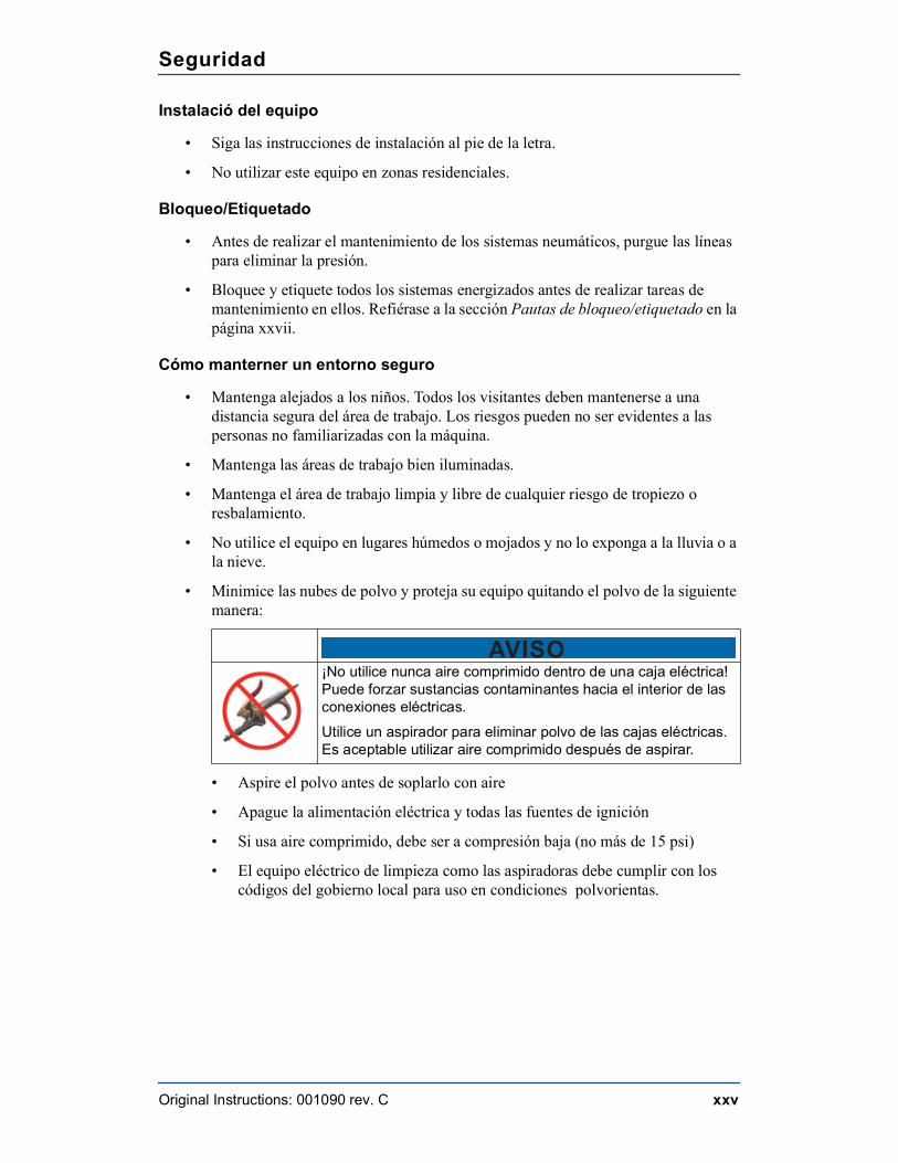
• Minimice las nubes de polvo y proteja su equipo quitando el polvo de la siguiente manera:
• Aspire el polvo antes de soplarlo con aire
• Apague la alimentación eléctrica y todas las fuentes de ignición
• Si usa aire comprimido, debe ser a compresión baja (no más de 15 psi)
• El equipo eléctrico de limpieza como las aspiradoras debe cumplir con los códigos del gobierno local para uso en condiciones polvorientas.
AVISO¡No utilice nunca aire comprimido dentro de una caja eléctrica! Puede forzar sustancias contaminantes hacia el interior de las conexiones eléctricas. Utilice un aspirador para eliminar polvo de las cajas eléctricas. Es aceptable utilizar aire comprimido después de aspirar.
Seguridad
Original Instructions: 001090 rev. C xxvi
Uso y mantenimiento del equipo
• Asegúrese de que no haya personas, herramientas y objetos extraños en las zonas restringidas antes de utilizar este equipo. Las zonas restringidas se indican en la página xxxii.
• Realice pruebas de seguridad para verificar que todos los frenos de emergencia funcionen adecuadamente antes de utilizar el equipo al principio de la puesta en marcha y después de realizar cualquier tarea de mantenimiento.
• En caso de que la máquina no funcione correctamente, deténgala inmediatamente utilizando un freno de emergencia e informe el problema a un supervisor.
• No deje nunca la máquina encendida si no está junto a ella. ¡Apáguela! No la abandone hasta que todas las piezas se detengan completamente y hasta que se haya apagado la alimentación eléctrica.
• Verifique periódicamente que no haya piezas gastadas o dañadas. Repárelas o cámbielas inmediatamente.
• Mantenga los sistemas neumáticos y eléctricos en buen funcionamiento en todo momento. Repare las fugas y las conexiones sueltas inmediatamente. No exceda nunca la presión ni potencia eléctrica recomendadas.
• Verifique que todos los dispositivos de seguridad estén en buen funcionamiento antes de comenzar cada turno. Todos los dispositivos protectores y de seguridad deben estar en su lugar antes y durante el uso de la máquina. No desconecte ni evite nunca ningún dispositivo de seguridad ni interbloqueo eléctrico.
• Solo el personal de mantenimiento calificado puede quitar o instalar los dispositivos de seguridad.
• Inspeccione periódicamente la calidad del producto terminado.
Seguridad eléctrica
• No utilice líquidos en el interior de los gabinetes eléctricos.
• Cuando utilice disolventes sobre o alrededor de la máquina, desconecte la alimentación para eliminar las probabilidades de chispas, que pueden producir una explosión o incendio. Use un respirador aprobado para el uso con disolventes. Use ropa protectora, guantes y lentes de seguridad.
Seguridad
Original Instructions: 001090 rev. C xxvii
Bloqueo/Etiquetado
Pautas de bloqueo/etiquetado
Deben cumplir con todas las pautas de bloqueo/etiquetado conforme a la norma OSHA 29 CFR 1910.147. El programa de control de energía de la compañía debe incluir un procedimiento específico. El objetivo de este manual no es reemplazar el procedimiento de desenergización o bloqueo/etiquetado requerido por la OSHA, sino proporcionar pautas orientativas generales.
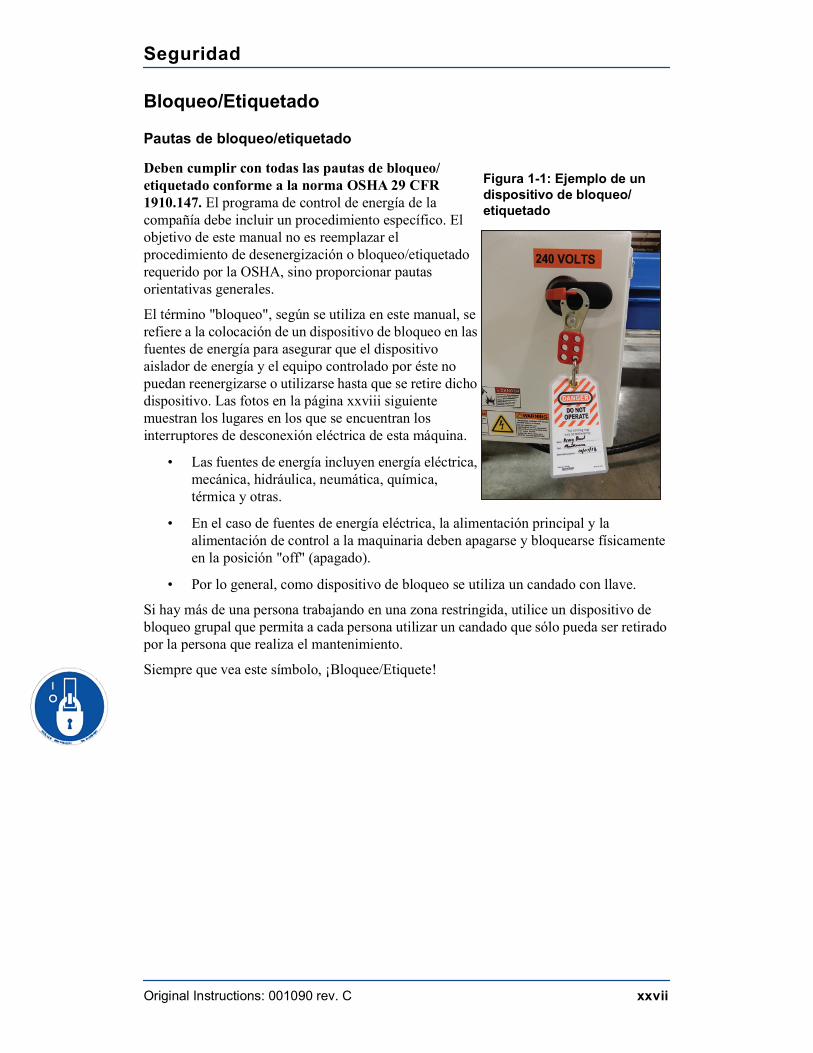
El término "bloqueo", según se utiliza en este manual, se refiere a la colocación de un dispositivo de bloqueo en las fuentes de energía para asegurar que el dispositivo aislador de energía y el equipo controlado por éste no puedan reenergizarse o utilizarse hasta que se retire dicho dispositivo. Las fotos en la página xxviii siguiente muestran los lugares en los que se encuentran los interruptores de desconexión eléctrica de esta máquina.
• Las fuentes de energía incluyen energía eléctrica, mecánica, hidráulica, neumática, química, térmica y otras.
• En el caso de fuentes de energía eléctrica, la alimentación principal y la alimentación de control a la maquinaria deben apagarse y bloquearse físicamente en la posición "off" (apagado).
• Por lo general, como dispositivo de bloqueo se utiliza un candado con llave.
Si hay más de una persona trabajando en una zona restringida, utilice un dispositivo de bloqueo grupal que permita a cada persona utilizar un candado que sólo pueda ser retirado por la persona que realiza el mantenimiento.
Siempre que vea este símbolo, ¡Bloquee/Etiquete!
Figura 1-1: Ejemplo de un dispositivo de bloqueo/etiquetado
Seguridad
Original Instructions: 001090 rev. C xxviii
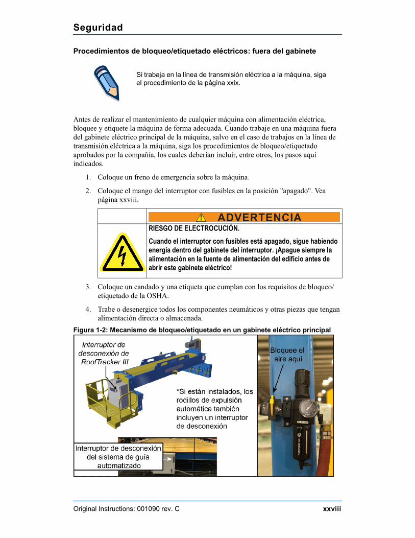
Procedimientos de bloqueo/etiquetado eléctricos: fuera del gabinete
Antes de realizar el mantenimiento de cualquier máquina con alimentación eléctrica, bloquee y etiquete la máquina de forma adecuada. Cuando trabaje en una máquina fuera del gabinete eléctrico principal de la máquina, salvo en el caso de trabajos en la línea de transmisión eléctrica a la máquina, siga los procedimientos de bloqueo/etiquetado aprobados por la compañía, los cuales deberían incluir, entre otros, los pasos aquí indicados.
1. Coloque un freno de emergencia sobre la máquina.
2. Coloque el mango del interruptor con fusibles en la posición "apagado". Vea página xxviii.
3. Coloque un candado y una etiqueta que cumplan con los requisitos de bloqueo/etiquetado de la OSHA.
4. Trabe o desenergice todos los componentes neumáticos y otras piezas que tengan alimentación directa o almacenada.
Figura 1-2: Mecanismo de bloqueo/etiquetado en un gabinete eléctrico principal
Si trabaja en la línea de transmisión eléctrica a la máquina, siga el procedimiento de la página xxix.
! ADVERTENCIARIESGO DE ELECTROCUCIÓN.Cuando el interruptor con fusibles está apagado, sigue habiendo energía dentro del gabinete del interruptor. ¡Apague siempre la alimentación en la fuente de alimentación del edificio antes de abrir este gabinete eléctrico!
Seguridad
Original Instructions: 001090 rev. C xxix
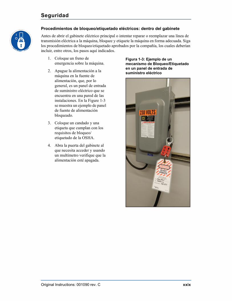
Procedimientos de bloqueo/etiquetado eléctricos: dentro del gabineteAntes de abrir el gabinete eléctrico principal o intentar reparar o reemplazar una línea de transmisión eléctrica a la máquina, bloquee y etiquete la máquina en forma adecuada. Siga los procedimientos de bloqueo/etiquetado aprobados por la compañía, los cuales deberían incluir, entre otros, los pasos aquí indicados.
1. Coloque un freno de emergencia sobre la máquina.
2. Apague la alimentación a la máquina en la fuente de alimentación, que, por lo general, es un panel de entrada de suministro eléctrico que se encuentra en una pared de las instalaciones. En la Figure 1-3 se muestra un ejemplo de panel de fuente de alimentación bloqueado.
3. Coloque un candado y una etiqueta que cumplan con los requisitos de bloqueo/etiquetado de la OSHA.
4. Abra la puerta del gabinete al que necesita acceder y usando un multímetro verifique que la alimentación esté apagada.
Figura 1-3: Ejemplo de un mecanismo de Bloqueo/Etiquetado en un panel de entrada de suministro eléctrico
Seguridad
Original Instructions: 001090 rev. C xxx
Procedimiento de bloqueo/etiquetado del sistema neumático: cuando no se requiere bloqueo/etiquetado
Si trabaja con componentes que no son del sistema neumático pero que requieren su presencia en la proximidad de componentes neumáticos móviles, debe, como mínimo, trabar físicamente estos componentes para que no se muevan. Si no es posible, bloquee/etiquete todo el sistema neumático.
Procedimiento de bloqueo/etiquetado del sistema neumático: cuando se requiere bloqueo/etiquetado
Antes de intentar reparar o realizar el mantenimiento de una línea o componente neumático, bloquee/etiquete la máquina en forma apropiada. Vea la página xxviii para más detalles sobre procedimientos de bloqueo/etiquetado neumático. Siga los procedimientos de bloqueo/etiquetado aprobados por la compañía.
Solución de problemas con una máquina energizadaSólo un electricista calificado que utilice el equipo de protección personal y siga los procedimientos recomendados en la norma NFPA 70E debe intentar realizar tareas de reparación o mantenimiento en un área o componente energizados de la máquina o en su proximidad.
Cada vez que se realizan tareas de mantenimiento mientras el equipo está eléctricamente energizado, existe un riesgo potencial de formación de un arco eléctrico. Consulte en la norma NFPA 70E el equipo de protección personal requerido para trabajar con componentes eléctricamente energizados. Los componentes neumáticos e hidráulicos pueden moverse de manera imprevista si no se desenergizan. Trabe físicamente cualquier componente que pueda moverse cuando deba trabajar en ellos o en su proximidad.
Seguridad
Original Instructions: 001090 rev. C xxxi
Prueba de seguridadEste procedimiento de prueba DEBE ser realizado por personal calificado al momento de la puesta en marcha y después de CUALQUIER tarea de mantenimiento, ajuste o modificación.
1. Asegúrese de que la presión del aire esté ajustada en 100 psi. Vea Ajuste de la presión.
2. Accione todos los conjuntos neumáticos para comprobar que suban y bajen según lo previsto a una velocidad razonable.
Seguridad
Original Instructions: 001090 rev. C xxxii
Zona Restringida
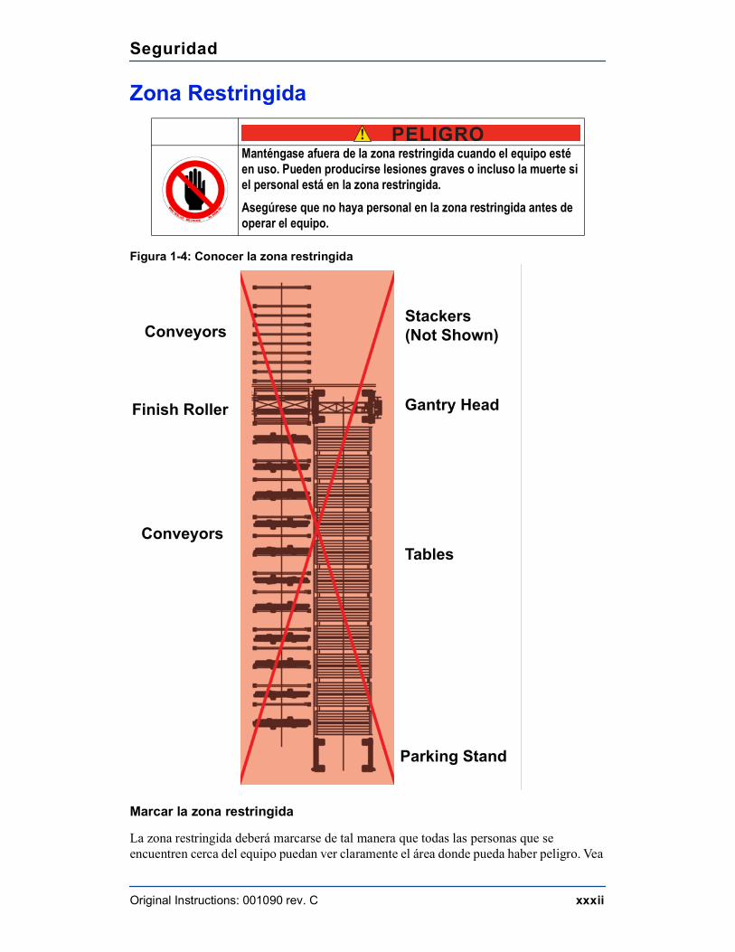
Figura 1-4: Conocer la zona restringida
Marcar la zona restringida
La zona restringida deberá marcarse de tal manera que todas las personas que se encuentren cerca del equipo puedan ver claramente el área donde pueda haber peligro. Vea
! PELIGROManténgase afuera de la zona restringida cuando el equipo esté en uso. Pueden producirse lesiones graves o incluso la muerte si el personal está en la zona restringida.Asegúrese que no haya personal en la zona restringida antes de operar el equipo.
Gantry Head
Tables
Parking Stand
Conveyors
Finish Roller
ConveyorsStackers (Not Shown)
Chapter 1
Original Instructions: 001090 rev. C 1
Introduction
Introduction to the Manual
Purpose of This ManualIn order for this manual to be useful, it must be accessible.
This manual addresses the most recent version of the equipment as of the date listed on the title page. For earlier revisions, contact MiTek Machinery Division Customer Service.
This manual is a valuable training tool.
• The Introduction and General Information chapters discuss contact information for MiTek and provide basic information about the equipment.
• The Operation chapter teaches operators how to efficiently operate the machine.• The Maintenance chapter details procedures specifically for maintenance
personnel.• The appendices provide valuable training materials and technical information to
keep your equipment running.
Purpose of Chapter
This chapter explains how to navigate through the manual and how to contact MiTek Machinery Division Customer Service.
! WARNINGRead this manual completely before using this equipment. Do not operate this equipment until you have a thorough understanding of all controls, safety devices, emergency stops, and operating procedures outlined in this manual.All hazard instructions must be read and observed. Failure to do so may result in economic loss, property damage, and/or personal injury.This manual must always be available to personnel.
Introduction
Original Instructions: 001090 rev. C 2
Scope of This ManualThe Roof Truss Table is designed to work with optional accessories and other MiTek machines, but the scope of this manual is limited to the following equipment:
Equipment covered in this manual:
• Roof Truss Table
• Ejection Systems (High-Slope Auto-Eject and End-Eject)
Equipment not covered in this manual:
• Roof Press
• Automated or Manual Jigging
• Other peripheral equipment
The Drawing SetA list of drawings can be found in the back of this equipment manual or in a separate 11x17 binder. The drawings list can be found in the Drawing Set chapter.
Introduction
Original Instructions: 001090 rev. C 3
Navigational Aids
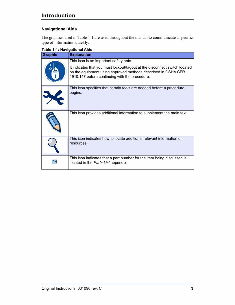
The graphics used in Table 1-1 are used throughout the manual to communicate a specific type of information quickly.
Table 1-1: Navigational AidsGraphic Explanation
This icon is an important safety note.It indicates that you must lockout/tagout at the disconnect switch located on the equipment using approved methods described in OSHA CFR 1910.147 before continuing with the procedure.
This icon specifies that certain tools are needed before a procedure begins.
This icon provides additional information to supplement the main text.
This icon indicates how to locate additional relevant information or resources.
This icon indicates that a part number for the item being discussed is located in the Parts List appendix.
Introduction
Original Instructions: 001090 rev. C 4
Additional Resources
WebsiteVisit the MiTek website at mitek-us.com for up-to-date information on all MiTek equipment. You may also find the following information there:
• The latest revisions of this manual
• Service bulletins pertaining to your equipment
• Support, safety, and training information
• Part numbers for ordering parts
Phone or E-mail SupportTo obtain expert technical assistance or to order parts, contact MiTek Machinery Division Customer Service using one of the following methods.
Contact InformationMiTek Component AutomationCustomer Service Department301 Fountain Lakes Industrial DriveSt. Charles, MO 63301
Parts Orders (with part number)Email: [email protected]
Technical AssistancePhone: 800-523-3380Fax: [email protected]
Websitemitek-us.com
VideosSearch for “MiTek Inc” to find us on YouTube.
Chapter 2
Original Instructions: 001090 rev. C 5
General Information
Introduction to the Equipment
Purpose of the Equipment
The Roof Truss Tables are used with MiTek roof truss presses. All accessories and options discussed in this manual are designed to work specifically with MiTek Roof Truss Tables to make setup and material handling tasks more efficient.
Description of the Equipment
The Roof Truss Tables provide a stable, durable jigging surface for the assembly and pressing of trusses. Trusses are assembled on the table surface and the press passes above the tables, embedding the plates.
Optional ejection systems can be installed in the tables to lift the trusses off the table for easy removal. Optional automated and manual jigging can also be installed to drastically reduce setup time.
Safety Compliance of the EquipmentEquipment shipped to a U.S. destination is compliant NFPA 79, NEC 2009, and applicable OSHA regulations.
Equipment shipped to an international destination is compliant with CSA regulations.
Purpose of Chapter This chapter provides an overview of the equipment and the means to identify it.
General Information
Original Instructions: 001090 rev. C 6
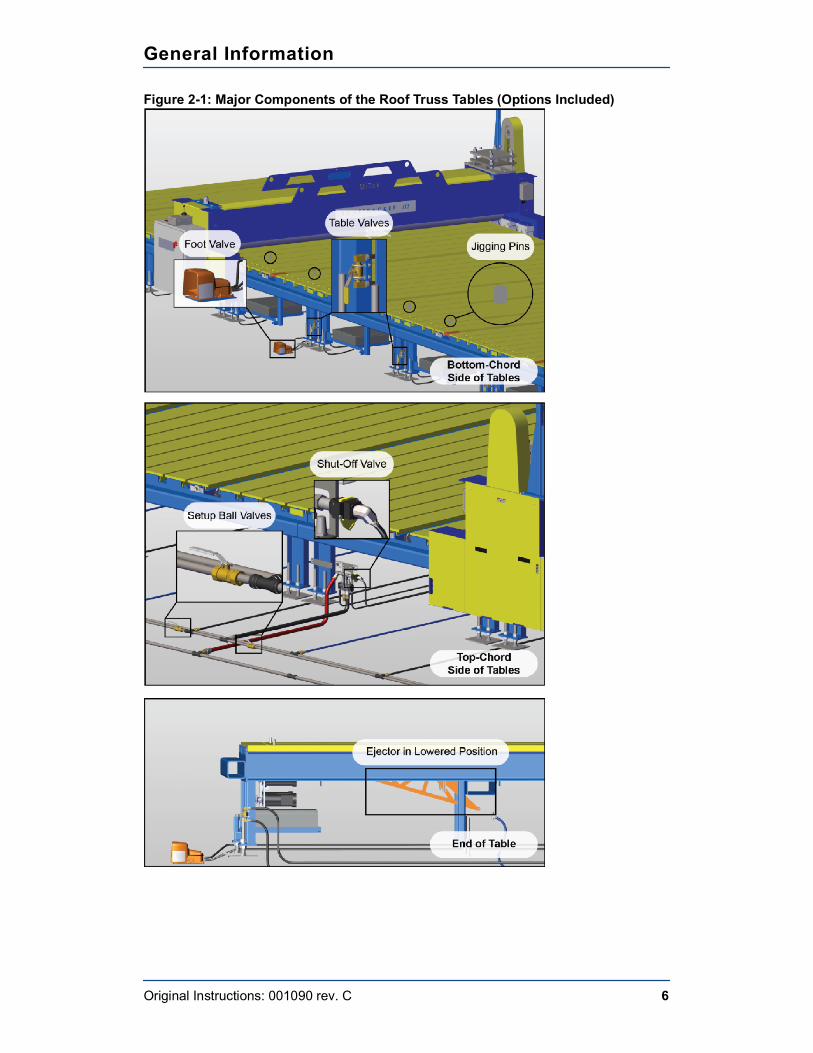
Figure 2-1: Major Components of the Roof Truss Tables (Options Included)
General Information
Original Instructions: 001090 rev. C 7
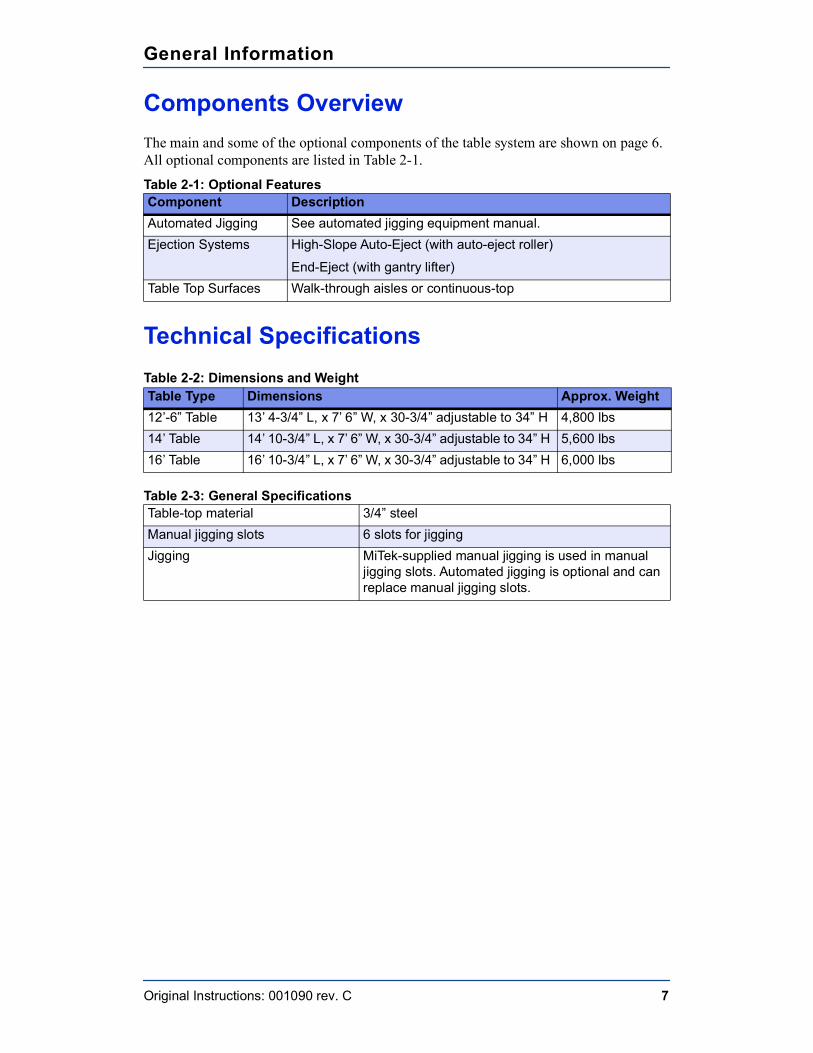
Components OverviewThe main and some of the optional components of the table system are shown on page 6. All optional components are listed in Table 2-1.
Table 2-1: Optional Features
Technical SpecificationsTable 2-2: Dimensions and Weight
Table 2-3: General Specifications
Component DescriptionAutomated Jigging See automated jigging equipment manual.Ejection Systems High-Slope Auto-Eject (with auto-eject roller)
End-Eject (with gantry lifter)Table Top Surfaces Walk-through aisles or continuous-top
Table Type Dimensions Approx. Weight12’-6” Table 13’ 4-3/4” L, x 7’ 6” W, x 30-3/4” adjustable to 34” H 4,800 lbs14’ Table 14’ 10-3/4” L, x 7’ 6” W, x 30-3/4” adjustable to 34” H 5,600 lbs16’ Table 16’ 10-3/4” L, x 7’ 6” W, x 30-3/4” adjustable to 34” H 6,000 lbs
Table-top material 3/4” steelManual jigging slots 6 slots for jiggingJigging MiTek-supplied manual jigging is used in manual
jigging slots. Automated jigging is optional and can replace manual jigging slots.
Chapter 3
Original Instructions: 001090 rev. C 8
Installation
Installation Requirements
Environmental Requirements
Operating Temperature
The Roof Gantry Tables operate properly in its intended ambient temperature, from 40 to 122 degrees Fahrenheit (0 to 50 degrees Celsius).
Relative Humidity
The Roof Gantry Tables operate properly in an atmosphere with 45 to 85 percent relative humidity.
Transportation and Storage
The Roof Gantry Tables withstand or has been protected against transportation and storage temperatures from -13 to 158 degrees Fahrenheit (-25 to 70 degrees Celsius). It has been packaged to prevent damage from the effects of normal humidity, vibration, and shock.
Infrastructure Requirements
Flooring Requirements
The Roof Gantry Tables need to be installed on a floor that meets the minimum requirements for the press that will be pressing on the tables. Refer to the press manual.
Purpose of Chapter
This chapter provides a brief overview of the responsibilities in the installation process.
ENVIRONMENTAL
Do not discard machinery into the municipal waste stream.
Installation
Original Instructions: 001090 rev. C 9
Pneumatic Requirements
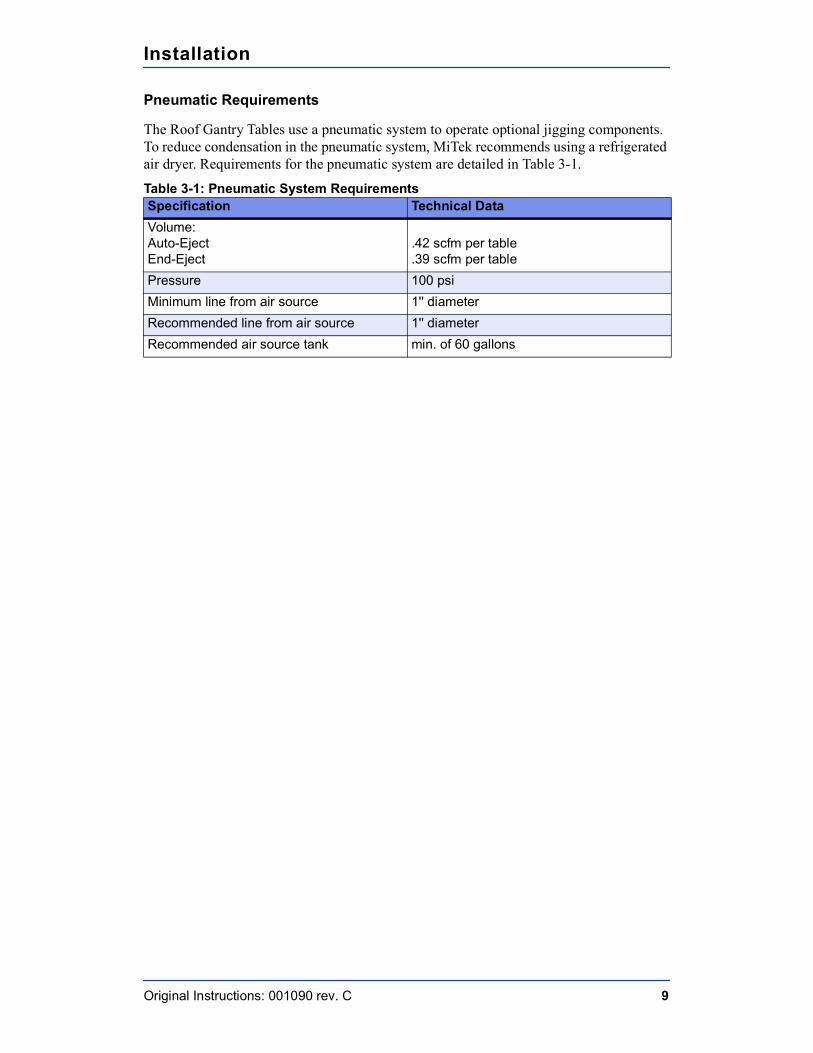
The Roof Gantry Tables use a pneumatic system to operate optional jigging components. To reduce condensation in the pneumatic system, MiTek recommends using a refrigerated air dryer. Requirements for the pneumatic system are detailed in Table 3-1.
Table 3-1: Pneumatic System Requirements Specification Technical DataVolume: Auto-EjectEnd-Eject
.42 scfm per table
.39 scfm per tablePressure 100 psiMinimum line from air source 1'' diameterRecommended line from air source 1'' diameterRecommended air source tank min. of 60 gallons
Installation
Original Instructions: 001090 rev. C 10
Responsibilities During InstallationMiTek supervises the installation to ensure that the Roof Gantry Tables are installed properly and operate correctly. MiTek will also provide operating and maintenance training at the time the equipment is installed. The customer is responsible for providing all labor and equipment needed to complete the installation.
Responsibilities Before Moving or Selling
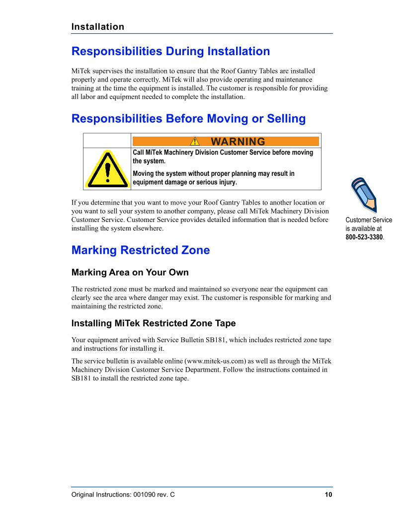
If you determine that you want to move your Roof Gantry Tables to another location or you want to sell your system to another company, please call MiTek Machinery Division Customer Service. Customer Service provides detailed information that is needed before installing the system elsewhere.
Marking Restricted Zone
Marking Area on Your OwnThe restricted zone must be marked and maintained so everyone near the equipment can clearly see the area where danger may exist. The customer is responsible for marking and maintaining the restricted zone.
Installing MiTek Restricted Zone TapeYour equipment arrived with Service Bulletin SB181, which includes restricted zone tape and instructions for installing it.
The service bulletin is available online (www.mitek-us.com) as well as through the MiTek Machinery Division Customer Service Department. Follow the instructions contained in SB181 to install the restricted zone tape.
! WARNINGCall MiTek Machinery Division Customer Service before moving the system.Moving the system without proper planning may result in equipment damage or serious injury.
Customer Service is available at 800-523-3380.
Installation
Original Instructions: 001090 rev. C 11
Local Codes and RegulationsThe customer must be familiar with all local codes that apply and ensure the equipment in installed in a way that meets these codes. The following list identifies some, but not all, of the items that should be discussed with local authorities.
• Equipment should be stable under all conditions of use, including seismic events• Fuse and disconnect regulations• Grounding regulations• Emissions regulations• Space required• Personal protective equipment required• Inspections required

Chapter 4
Original Instructions: 001090 rev. C 12
Operation
Before You Begin
Purpose of Chapter
This chapter describes operating mechanisms on this machine and the procedure to operate it in most circumstances.
! WARNINGELECTROCUTION, HIGH PRESSURE, CRUSH, AND CUT HAZARDS.Read this section AND the safety section in the preliminary pages before operating or maintaining this machine.Do not operate this machine until you have a thorough understanding of all controls, safety devices, E-stops, and operating procedures outlined in this manual.Read and observe all warnings. Failure to do so may result in economic loss, property damage, and/or personal injury.This manual must always be available to personnel operating and maintaining this machine.
! WARNINGCRUSH AND CUT HAZARD.Before turning on the machine, make sure that all personnel and other machines are out of the restricted zone (see page xvi).
! WARNINGDo not operate this machine unless all guards and safety devices are in place.Only qualified maintenance personnel shall repair, remove, or replace guards and safety devices.
Operation
Original Instructions: 001090 rev. C 13
Operator ControlsRefer to your press or automated jigging manual for additional operating information.
Stopping the MachineRefer to the press manual for instructions on stopping the press and other safety information.
Understanding the Table ComponentsThe pneumatic system controls the optional ejectors on the tables.
Control ValvesThis section describes how valves control individual tables or setups. A table line may have multiple setups depending on installation requirements.
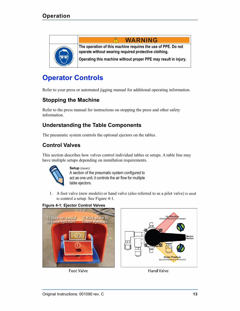
1. A foot valve (new models) or hand valve (also referred to as a pilot valve) is used to control a setup. See Figure 4-1.
Figure 4-1: Ejector Control Valves
! WARNING The operation of this machine requires the use of PPE. Do not
operate without wearing required protective clothing.Operating this machine without proper PPE may result in injury.
Setup (noun):A section of the pneumatic system configured to act as one unit; it controls the air flow for multiple table ejectors.
Operation
Original Instructions: 001090 rev. C 14
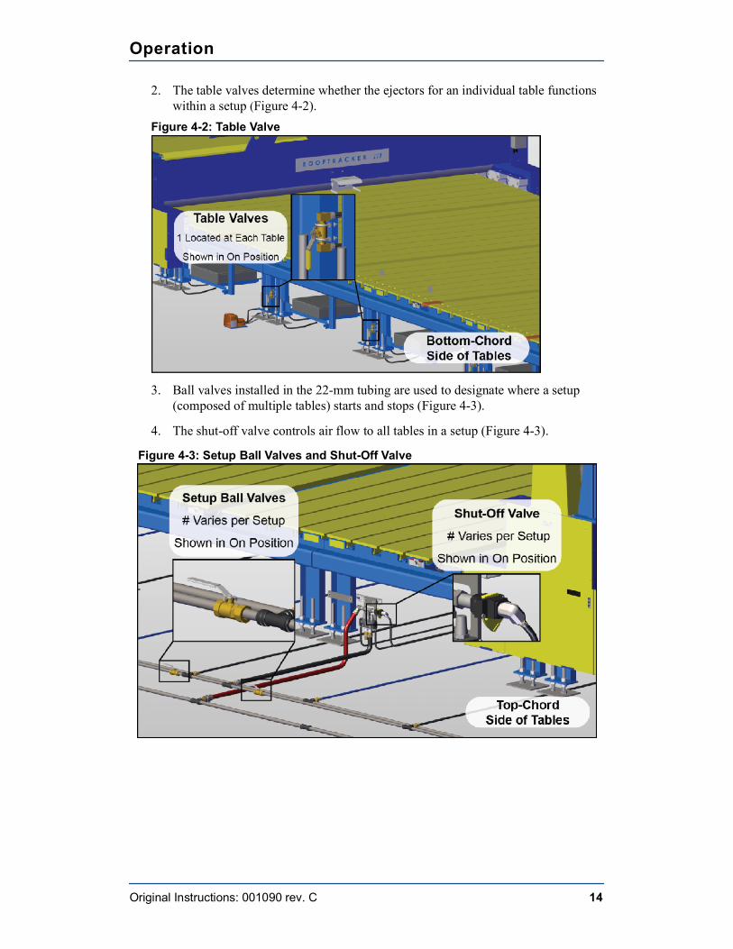
2. The table valves determine whether the ejectors for an individual table functions within a setup (Figure 4-2).
Figure 4-2: Table Valve
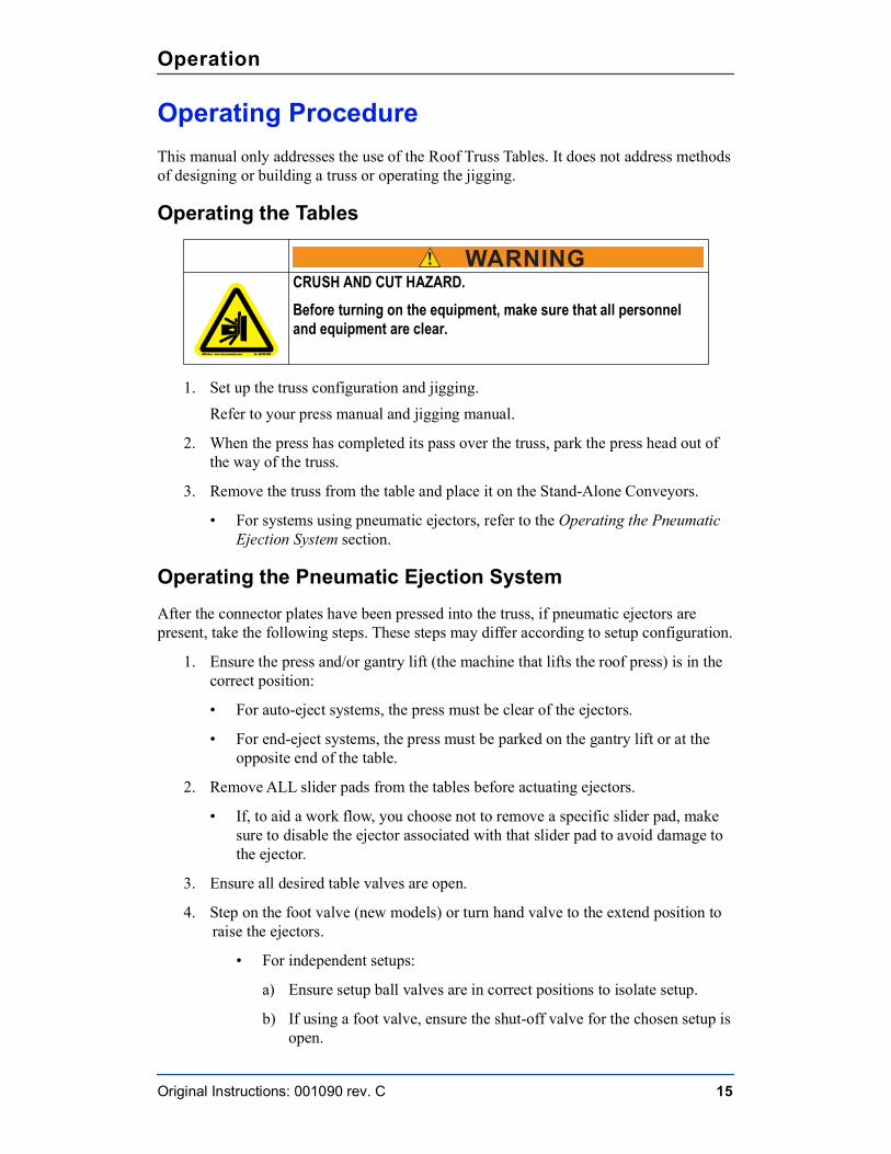
3. Ball valves installed in the 22-mm tubing are used to designate where a setup (composed of multiple tables) starts and stops (Figure 4-3).
4. The shut-off valve controls air flow to all tables in a setup (Figure 4-3).
Figure 4-3: Setup Ball Valves and Shut-Off Valve
Operation
Original Instructions: 001090 rev. C 15
Operating ProcedureThis manual only addresses the use of the Roof Truss Tables. It does not address methods of designing or building a truss or operating the jigging.
Operating the Tables
1. Set up the truss configuration and jigging.Refer to your press manual and jigging manual.
2. When the press has completed its pass over the truss, park the press head out of the way of the truss.
3. Remove the truss from the table and place it on the Stand-Alone Conveyors.
• For systems using pneumatic ejectors, refer to the Operating the Pneumatic Ejection System section.
Operating the Pneumatic Ejection SystemAfter the connector plates have been pressed into the truss, if pneumatic ejectors are present, take the following steps. These steps may differ according to setup configuration.
1. Ensure the press and/or gantry lift (the machine that lifts the roof press) is in the correct position:
• For auto-eject systems, the press must be clear of the ejectors.
• For end-eject systems, the press must be parked on the gantry lift or at the opposite end of the table.
2. Remove ALL slider pads from the tables before actuating ejectors.
• If, to aid a work flow, you choose not to remove a specific slider pad, make sure to disable the ejector associated with that slider pad to avoid damage to the ejector.
3. Ensure all desired table valves are open.
4. Step on the foot valve (new models) or turn hand valve to the extend position to raise the ejectors.
• For independent setups:
a) Ensure setup ball valves are in correct positions to isolate setup.
b) If using a foot valve, ensure the shut-off valve for the chosen setup is open.
! WARNINGCRUSH AND CUT HAZARD.Before turning on the equipment, make sure that all personnel and equipment are clear.
Operation
Original Instructions: 001090 rev. C 16
• For operating entire line as one:
a) Ensure all setup ball valves are in the open position.
b) If using a foot valve, Ensure the shut-off valve connected to the chosen foot valve is open and close all other shut-off valves.
c) If using a hand valve, ensure all hand valves are in the neutral position.
5. The ejectors lift the truss off the table.
• For ejection off the side of the tables, the truss should slide onto the Stand-Alone Conveyors. If auto-eject rollers are present and running, they will automatically assist with this step.
• On end-eject systems, the pop-up ejectors, the gantry lift, and the press (if parked on the gantry lift) will raise simultaneously. Push or pull the truss across the pop-up ejectors to transfer the truss to the end of the table line.
6. Retract the ejectors back into the table by kicking the foot valve plate (new models) or turning the hand valve to the retract position.
! WARNINGCRUSH HAZARD.When removing a truss from an end-eject system, use caution to avoid coming into contact with the Finish Roller.Failure to exercise caution may result in severe personal injury.
Chapter 5
Original Instructions: 001090 rev. C 17
Maintenance
Performing Maintenance SafelyRead the safety section starting on page vii and adhere to all rules and guidelines. This section provides additional safety information specific to maintenance topics.
The recommended intervals for the maintenance items addressed in this section are listed in Maintenance Checklist.
Before Operating This MachineReview these warnings before operating this machine.
Purpose of Chapter
This chapter provides step-by-step instructions and other information to help you make repairs and perform preventative maintenance.
! WARNINGHIGH PRESSURE, CRUSH, CUT, AND CHEMICAL HAZARDSRead this section AND the safety section in the preliminary pages before operating or maintaining this equipment.Do not operate this machine until you have a thorough understanding of all controls, safety devices, E-stops, and operating procedures outlined in this manual.Read and observe all hazard instructions. Failure to do so may result in economic loss, property damage, and/or personal injury. This manual must always be available to personnel operating and maintaining this equipment.
! WARNINGCRUSH AND CUT HAZARDGuards must always be in place during operation to avoid serious injury and possibly death.Always replace guards after completing maintenance and before removing the lockout/tagout device.
Maintenance
Original Instructions: 001090 rev. C 18
Lockout/TagoutThe lock and tag symbol shown here indicates that proper lockout/tagout procedures must be used prior to starting the procedure where the symbol occurs.
Important Safety Information
Your Responsibilities
Detailed descriptions of standard workshop procedures, safety principles, and service operations are not included in this manual. Although this manual contains some warnings and cautions against specific service methods which could cause personal injury or damage to the machine, it does not cover all conceivable ways of service which might be done or the possibility of hazardous consequences of each conceivable way. If you intend to handle, operate, or service the unit by a procedure or method not specifically recommended by the manufacturer, first make sure that such a procedure or method will not render this equipment unsafe or pose a threat to you and others.
It is the responsibility of the mechanic performing the maintenance or service on a particular machine to:
! WARNING CRUSH AND CUT HAZARD.
Before turning on the equipment, make sure that all personnel and equipment are clear.
! WARNING ELECTROCUTION AND HIGH PRESSURE HAZARDS
Always turn the power off by activating an E-stop when the equipment is not in operation.Always verify that all power to the machine has been turned off and follow approved lockout/tagout safety procedures (OSHA 29 CFR 1910.147) before performing any maintenance on this equipment.If it is absolutely necessary to troubleshoot an energized machine, follow NFPA 70E or the governing regulations at your location for proper procedures and personal protective equipment.The components on this machine can cause severe injury if adjusted improperly. Follow all procedures in this manual and do not make adjustments to the machine without guidance from MiTek or MiTek documentation.Only trained personnel should make mechanical adjustments to this machine.
Maintenance
Original Instructions: 001090 rev. C 19
1. Inspect the machine for abnormal wear and damage;
2. Choose a procedure which will not endanger his or her safety, the safety of others, the equipment, or the safe operation of the machine;
3. Fully inspect and test the machine and the hydraulic, pneumatic and electrical systems to ensure that the service to the machine has been properly performed and that the machine, hydraulic, pneumatic and electric systems will function properly; and
4. Ensure only qualified electricians perform electrical service work.
General Service Rules
1. The design may change or upgrades may occur for any particular component. Always contact the factory before replacing components.
2. If inspection or testing reveals evidence of abnormal wear or damage to the machine or if you encounter circumstances not covered in the equipment manual—STOP—and consult MiTek. The machine must be repaired and serviced according to the current specifications and procedures of MiTek, using replacement parts with properties equal to or greater than those specified by MiTek.
3. Use the correct tools and procedures on this machine, to avoid damage and incorrect assembly.
4. Always install new gaskets, O-rings, cotter pins, etc., and place Loctite on bolts, if required.
5. Torque bolts and fasteners to the correct specifications.
6. Clean parts in a nonflammable or high-flash-point solvent only.
7. Lubricate any sliding surfaces before assembly.
8. Many components are manufactured from high carbon, heat-treated steel. Do not attempt to cold straighten, hot straighten, bend, or weld these components, as they may fail under load causing serious personal injury or death.
! WARNING
This machine uses high-voltage electricity, which may cause serious personal injury or death.
NOTICENever use compressed air inside an electrical enclosure. It may force contaminants into electrical connections.Use a vacuum to remove dust from electrical enclosures. Canned air is acceptable after vacuuming.
Maintenance
Original Instructions: 001090 rev. C 20
9. After re-assembly, check all parts for proper installation and operation before putting the machine back into service.
10. It is beneficial to record all major maintenance and testing. This allows recurring problems to be predicted and addressed before any production time is lost. Typical reports and records should include:
• Date
• Serial number of machine
• Description of problems or symptoms
• Corrective action taken
• Parts required
11. MiTek will, from time to time, mail out service bulletins and updates for this machine. Follow the service bulletins and updates accordingly and file them in this equipment manual.
Making Adjustments and Replacing PartsBe careful when making mechanical adjustments. Untrained personnel may damage the machine or cause harm to themselves and others.
Special materials have been used for some of the components of this equipment. It is critical to the future performance of this machine that only specified replacement parts are used. Order all replacement parts through MiTek. Do not substitute parts without first consulting MiTek to determine if it is safe and effective. No electrical system component, cable, connector, or device should be modified, removed, disconnected, changed without specific approval and guidance from MiTek.
! WARNINGCRUSH AND CUT HAZARDSAlways replace guards after servicing.Only qualified maintenance personnel shall repair, remove, or replace guards and safety devices.
NOTICEFailure to follow the step-by-step procedures in this chapter may result in incorrect adjustment of this machine. Only trained maintenance personnel should make mechanical adjustments to this machine.Use only the exact replacement parts specified in this manual.
Maintenance
Original Instructions: 001090 rev. C 21
Wearing Personal Protective Equipment
Testing the Safety of the MachineThe test procedure in the Safety section starting on page xv MUST be performed by qualified personnel after ANY maintenance, adjustment, or modification.
The test should be performed before each shift starts to make sure that the safety features remain in working order.
Cleaning and Inspecting
CleaningIf it should become necessary to clean this machine, disconnect it from its power source first. Do not use liquid cleaners, aerosols, abrasive pads, scouring powders or solvents, such as benzene or alcohol. Use a soft cloth lightly moistened with a mild detergent solution. Make sure the surface cleaned is fully dry before reconnecting power.
Use pneumatic air to regularly blow dust and debris off of the tables, ejection components, and rollers. Make sure truss plates or other sharp objects are clear of all pneumatic and electrical systems.
! CAUTIONFollow OSHA guidelines to utilize the proper personal protective equipment (PPE) while performing maintenance. The most common include eye protection, hearing protection, dust masks while blowing off sawdust, gloves while working with solvents, and fire retardant clothing when troubleshooting an energized machine.
! CAUTIONCRUSH AND CUT HAZARDAlways replace guards after completing maintenance and before removing the lockout/tagout device.Operating a machine with guards removed may result in serious injury or death.
NOTICENever use compressed air inside of electrical enclosures. It may force contaminants into electrical connections.Use a vacuum to remove dust from electrical enclosures. Canned air is acceptable after vacuuming.
Maintenance
Original Instructions: 001090 rev. C 22
Inspecting the Ejectors
Check the clevis pin in the bell crank and all bolts for wear every three (3) months. Check bumpers on the high-slope auto-ejectors for wear or damage and replace as needed. See XX for the location of each ejector bumper and replacement instructions. If bumpers are not replaced, the link arm’s pivot holes will wallow out and cause premature failure. Replace all other worn parts.
Inspecting the Ejection System as a WholeCheck that the tables are level with the auto-eject rollers on an annual basis.
Pneumatic System MaintenanceThe pneumatic system controls the ejectors on the tables and the receiver stands (if present).
Removing Pressure from the Pneumatic SystemMost procedures involving the pneumatic system require the removal of pressure. Use the following procedure to remove pressure from the system.
1. Prepare the pneumatic system to remove pressure:
a) In systems with foot valves (new models), ensure all shut-off valves are in the open position.
b) In systems with hand valves, ensure all hand valves are in the neutral position.
2. Push the system shut-off valve on the filter/regulator assembly to the lockout position so it cuts off air flow. See Figure 5-1.
3. Lockout/tagout through the hole on the yellow slide. See Figure 5-1.
4. Check the air pressure gauge reads 0 psi and actuate an ejector control valve (the ejectors should not raise) to make sure all pressure has been bled from the system.
! CAUTIONHIGH PRESSURE HAZARD.Bleed all pressure from pneumatic lines before performing maintenance on pneumatic components.Pressurized components may move suddenly or vent air to atmosphere, causing injury.
Maintenance
Original Instructions: 001090 rev. C 23
Filter/RegulatorThe filter/regulator can be purchased directly from MiTek. Refer to the Parts List chapter for instructions on ordering parts.
Replacing the Filter Element
The regulator uses a 40-micron filter element that must be replaced every six (6) months. This filter can be purchased from MiTek. Refer to the Parts List chapter for instructions on ordering parts.
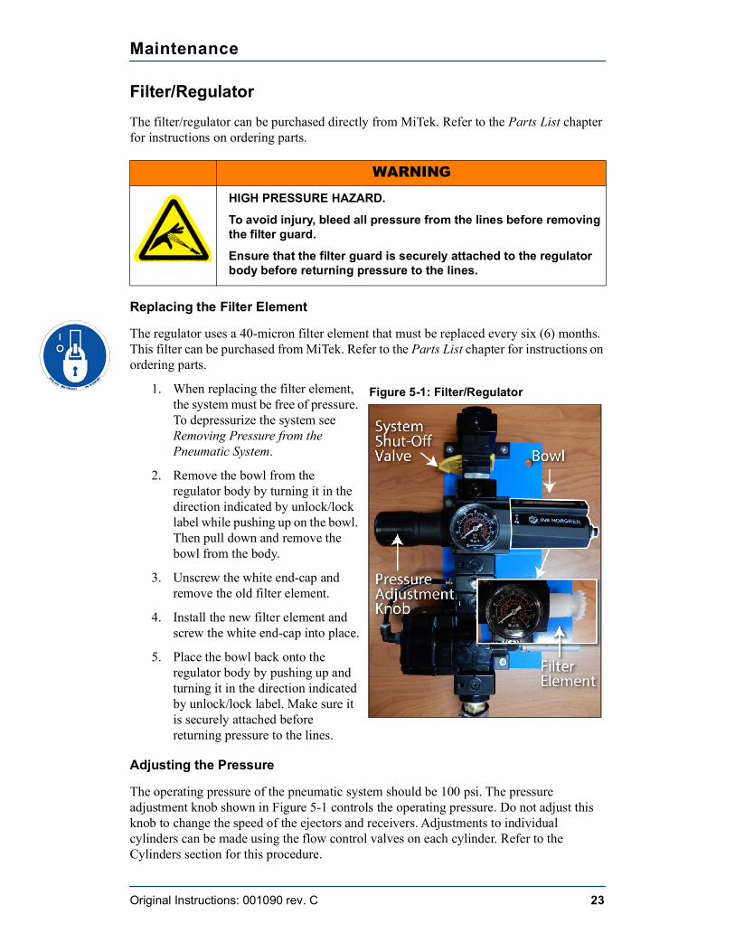
1. When replacing the filter element, the system must be free of pressure. To depressurize the system see Removing Pressure from the Pneumatic System.
2. Remove the bowl from the regulator body by turning it in the direction indicated by unlock/lock label while pushing up on the bowl. Then pull down and remove the bowl from the body.
3. Unscrew the white end-cap and remove the old filter element.
4. Install the new filter element and screw the white end-cap into place.
5. Place the bowl back onto the regulator body by pushing up and turning it in the direction indicated by unlock/lock label. Make sure it is securely attached before returning pressure to the lines.
Adjusting the Pressure
The operating pressure of the pneumatic system should be 100 psi. The pressure adjustment knob shown in Figure 5-1 controls the operating pressure. Do not adjust this knob to change the speed of the ejectors and receivers. Adjustments to individual cylinders can be made using the flow control valves on each cylinder. Refer to the Cylinders section for this procedure.
WARNING
HIGH PRESSURE HAZARD.
To avoid injury, bleed all pressure from the lines before removing the filter guard.
Ensure that the filter guard is securely attached to the regulator body before returning pressure to the lines.
Figure 5-1: Filter/Regulator
Maintenance
Original Instructions: 001090 rev. C 24
To adjust the system pressure to 100 psi:
1. Unlock the pressure adjustment knob on the filter/regulator by pulling it straight up.
2. Turn the knob clockwise to increase pressure or counterclockwise to decrease pressure.
3. Once a pressure of 100 psi is achieved, push the knob down to lock it in place.
Manual Drain
The latest model of the filter/regulator automatically drains accumulated liquid. Previous models of the filter/regulator require manual draining. At the bottom of the filter/regulator is a thumbscrew that operates a drain. When condensation gathers in pneumatic lines, it will show in the bowl’s sight glass. Where the sight glass comes in contact with water, it turns red, indicating the water level. Open this drain periodically to drain fluid from the system.
Additional Maintenance
If a filter/regulator is not operating at its optimum capacity, we recommend cleaning the regulator and replacing the O-rings, gaskets, diaphragm, and valve assembly. Refer to the Parts List chapter for instructions on ordering parts.
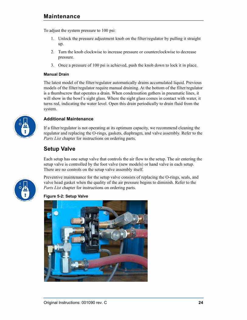
Setup ValveEach setup has one setup valve that controls the air flow to the setup. The air entering the setup valve is controlled by the foot valve (new models) or hand valve in each setup. There are no controls on the setup valve assembly itself.
Preventive maintenance for the setup valve consists of replacing the O-rings, seals, and valve head gasket when the quality of the air pressure begins to diminish. Refer to the Parts List chapter for instructions on ordering parts.
Figure 5-2: Setup Valve
Maintenance
Original Instructions: 001090 rev. C 25
Control Valves
Foot Valve
A foot valve (new models) controls the air flow for one setup. If you experience any issues with a foot valve, contact MiTek Machinery Division Customer Service. See Contact Information.
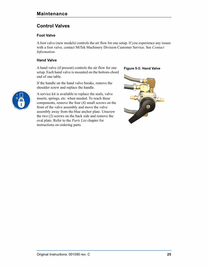
Hand Valve
A hand valve (if present) controls the air flow for one setup. Each hand valve is mounted on the bottom-chord end of one table.
If the handle on the hand valve breaks, remove the shoulder screw and replace the handle.
A service kit is available to replace the seals, valve inserts, springs, etc. when needed. To reach these components, remove the four (4) small screws on the front of the valve assembly and move the valve assembly away from the blue anchor plate. Unscrew the two (2) screws on the back side and remove the oval plate. Refer to the Parts List chapter for instructions on ordering parts.
Figure 5-3: Hand Valve
Maintenance
Original Instructions: 001090 rev. C 26
Ejector Cylinders
Adjusting Cushion Valves
Some cylinders have adjustable cushion valves to decelerate the load and reduce potentially destructive energy. These cushion valves sometimes need fine tuning to find their ideal cushioning between the completely closed and completely open positions.
• A completely closed cushion valve causes the cylinder to slow abruptly near the end of its stroke, increasing the cycle time.
• A completely open cushion valve prevents the cylinder from decelerating the load, producing a jarring end impact.
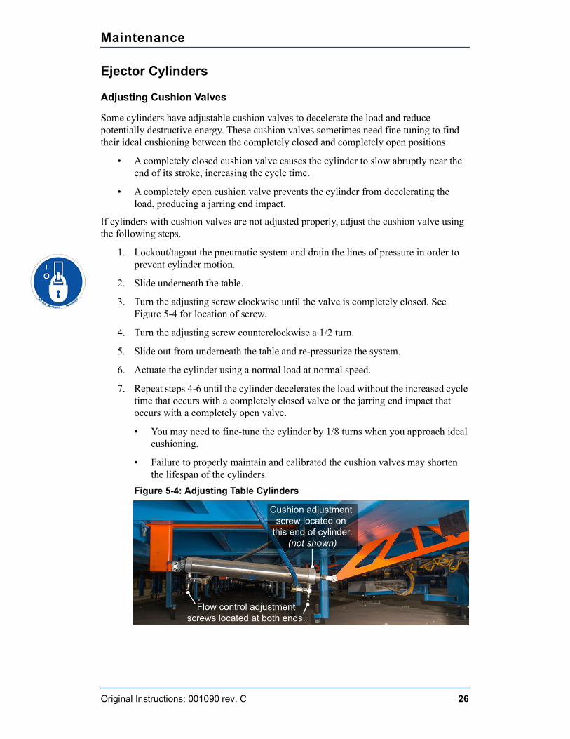
If cylinders with cushion valves are not adjusted properly, adjust the cushion valve using the following steps.
1. Lockout/tagout the pneumatic system and drain the lines of pressure in order to prevent cylinder motion.
2. Slide underneath the table.
3. Turn the adjusting screw clockwise until the valve is completely closed. See Figure 5-4 for location of screw.
4. Turn the adjusting screw counterclockwise a 1/2 turn.
5. Slide out from underneath the table and re-pressurize the system.
6. Actuate the cylinder using a normal load at normal speed.
7. Repeat steps 4-6 until the cylinder decelerates the load without the increased cycle time that occurs with a completely closed valve or the jarring end impact that occurs with a completely open valve.
• You may need to fine-tune the cylinder by 1/8 turns when you approach ideal cushioning.
• Failure to properly maintain and calibrated the cushion valves may shorten the lifespan of the cylinders.
Figure 5-4: Adjusting Table Cylinders
Flow control adjustmentscrews located at both ends.
Cushion adjustment screw located on
this end of cylinder.(not shown)
Maintenance
Original Instructions: 001090 rev. C 27
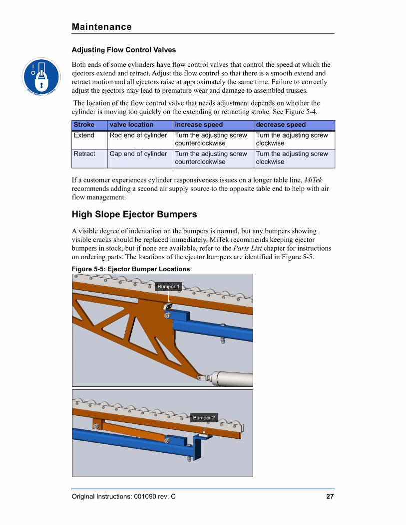
Adjusting Flow Control Valves
Both ends of some cylinders have flow control valves that control the speed at which the ejectors extend and retract. Adjust the flow control so that there is a smooth extend and retract motion and all ejectors raise at approximately the same time. Failure to correctly adjust the ejectors may lead to premature wear and damage to assembled trusses.
The location of the flow control valve that needs adjustment depends on whether the cylinder is moving too quickly on the extending or retracting stroke. See Figure 5-4.
If a customer experiences cylinder responsiveness issues on a longer table line, MiTek recommends adding a second air supply source to the opposite table end to help with air flow management.
High Slope Ejector BumpersA visible degree of indentation on the bumpers is normal, but any bumpers showing visible cracks should be replaced immediately. MiTek recommends keeping ejector bumpers in stock, but if none are available, refer to the Parts List chapter for instructions on ordering parts. The locations of the ejector bumpers are identified in Figure 5-5.
Figure 5-5: Ejector Bumper Locations
Stroke valve location increase speed decrease speedExtend Rod end of cylinder Turn the adjusting screw
counterclockwiseTurn the adjusting screw clockwise
Retract Cap end of cylinder Turn the adjusting screw counterclockwise
Turn the adjusting screw clockwise
Bumper 1
Bumper 2
Maintenance
Original Instructions: 001090 rev. C 28
Replacing a Ejector Bumper
1. Lockout/tagout the pneumatic system. See Removing Pressure from the Pneumatic System.
2. Once pressure has been removed from the pneumatic system, the ejectors should move freely. Use a board or other sturdy material to wedge the ejectors in an upward position to allow access to the bumpers.
3. Use a hex key to loosen the bolts securing the bumper and remove it.
4. Use a hex key to secure the new bumper using the existing bolts.
5. Remove the material used to wedge the ejectors into an upward position to ensure the ejectors can move freely.
Appendix A
Original Instructions: 001090 rev. C 29
Troubleshooting
Safety Notes for Troubleshooting
General Troubleshooting Safety Tips
• Read all warnings located in the safety section in the preliminary pages and adhere to them at all times.
• When the blue lock shown in the margin appears, lockout/tagout at the disconnect switch located on the equipment using approved methods described in OSHA 29 CFR 1910.147 before continuing with the procedure or troubleshooting.
• If the lockout/tagout graphic does not appear, it is recommended that you still de-energize the machine unless energy is required for the troubleshooting process. If it is absolutely necessary to troubleshoot an energized machine, follow NFPA 70E for proper procedures and personal protective equipment.
• All electrical work must be performed by a licensed electrician.
• Read this manual for information and procedures related to the specific maintenance or troubleshooting issue before attempting any maintenance.
• Safety goggles and a dust mask must be worn for all cleaning steps outlined in this manual. When using cleaning and lubrication solutions, a respirator rated for use with those solutions must be worn, as well as gloves resistant to the solution.
Purpose of Appendix
This appendix describes possible problems and solutions that you may encounter while operating the Roof Truss Tables.
! WARNINGELECTROCUTION, HIGH PRESSURE, CRUSH, CUT, AND CHEMICAL HAZARDS.Read all notes in this section AND the safety section in the preliminary pages before operating or maintaining this equipment.Most solutions are described in more detail in the Maintenance chapter, where there may be additional safety notes.
Troubleshooting
Original Instructions: 001090 rev. C 30
Electrical Troubleshooting Safety Tips• Make sure that you have the proper tools for the job. See page 31.
• Make sure that the person performing the troubleshooting is qualified from an electrical knowledge standpoint. If you feel uncertain about troubleshooting electrical power, remember that the cost of an injury far outweighs the cost of hiring an electrician.
• Remove rings or watches. They are extremely conductive material and may catch on small components.
• Get a helper. You are most likely going to need an extra hand at some point, and you shouldn’t perform electrical work without someone close by to help if you get injured.
• Be patient. Take your time and stay alert. Never take shortcuts or become too confident in what you are doing.
• Take notes recording what you have checked and what the readings were. This is a good way to check your work when you are finished. Sometimes, the machine won’t work because a wire was removed for testing and overlooked when cleaning up. Having notes makes the process go much more smoothly.
• ALWAYS turn the power off if you are checking for ohms or swapping PLC cards.
• ALWAYS push an E-stop button before approaching a machine for any reason. If you are working on encoders, pushing an E-stop is especially important. An interruption to a powered encoder may cause components to move without warning.
• Wear appropriate PPE (personal protective equipment) for working with live power.
Troubleshooting
Original Instructions: 001090 rev. C 31
Getting Started with Troubleshooting
Tools RequiredWhen the toolbox shown in the margin appears, you should gather the tools listed below it before beginning the procedure next to which it appears.
Before beginning the troubleshooting process or calling MiTek Machinery Division Customer Service, gather the following tools:
• Insulated slotted screwdriver
• Insulated Phillips screwdriver
• Equipment manual and drawings, including any electrical schematics
• Pen and notepad
• Multimeter
A multimeter is an electronic measuring instrument. The analog versions were referred to as a volt-ohm-meter (VOM). Digital models are referred to as digital multimeters (DMM). Your multimeter should have the following features:
• Voltage (volts) measurement
• Resistance (ohms) measurement
• Current (amps) measurement
• Ability to measure both AC and DC power
• Autoranging feature
• PPE as required by NFPA 70e
Troubleshooting
Original Instructions: 001090 rev. C 32
First Steps
Mechanical Troubleshooting
Always clean and lubricate the equipment as a first step in most troubleshooting processes. Most mechanical malfunctions are caused by inadequate preventative maintenance.
Electrical Troubleshooting
1. Lockout/tagout at the disconnect switch located on the equipment.
2. Vacuum and dust the electrical enclosure.
3. Remove the lockout/tagout equipment and attempt to run the Roof Truss Tables again. If that did not solve the problem, proceed with the next step.
4. Adhere to all regulations and guidelines given in NFPA 70e and in your company’s energy control program. Some important safety tips are addressed on page 29.
5. Determine where the electrical problem begins. To do this, you need a multimeter.
• Determine if you are working with AC (alternating current) or DC (direct current) before checking voltage.
• Measure incoming and outgoing voltage to and from components. Proceed in a logical order determined by your machine’s specific problem, and write down the order that you check each component and the amount of voltage that the multimeter registers.
NOTICENever use compressed air inside an electrical enclosure. It may force contaminants into electrical connections.Use a vacuum to remove dust from electrical enclosures. Canned air is acceptable after vacuuming.
! WARNINGELECTRICUTION HAZARD.All electrical work must be performed by a licensed electrician.If it is absolutely necessary to troubleshoot an energized machine, follow appropriate guidelines.
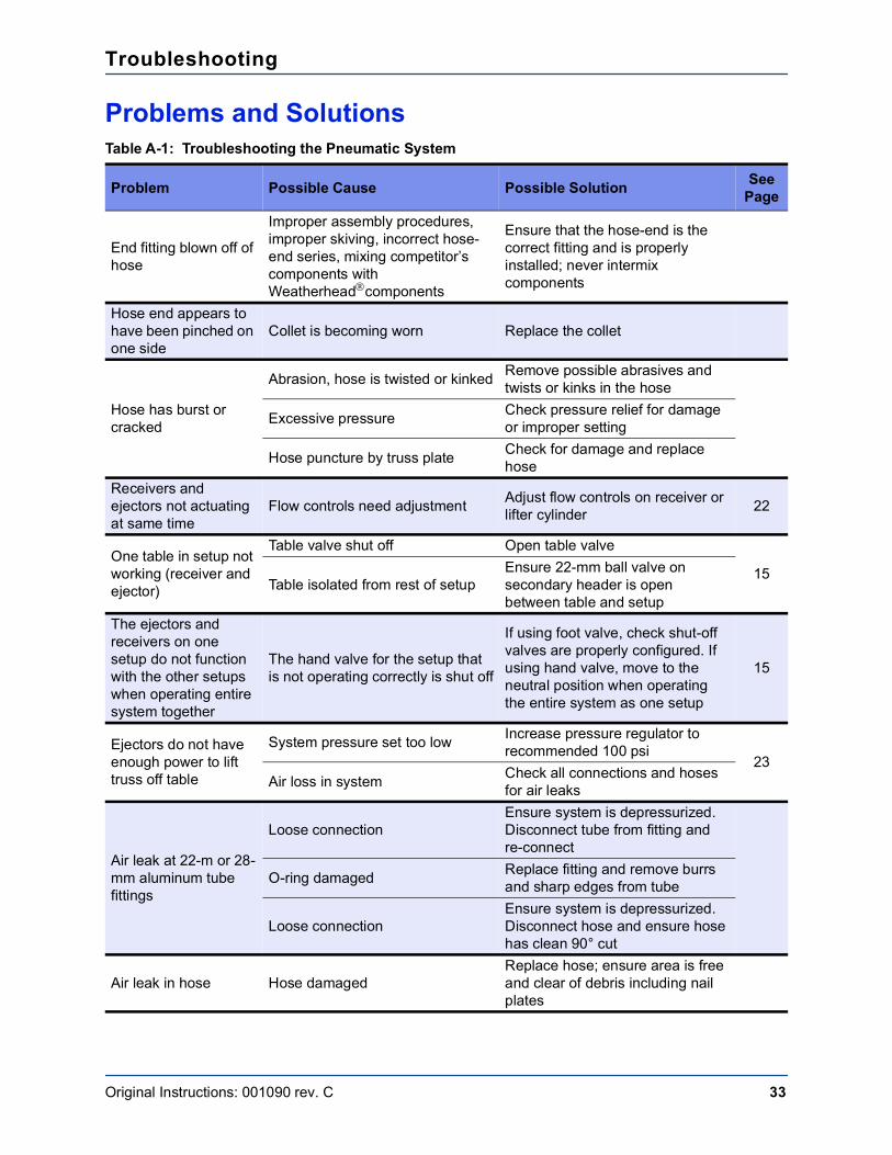
Troubleshooting
Original Instructions: 001090 rev. C 33
Problems and SolutionsTable A-1: Troubleshooting the Pneumatic System
Problem Possible Cause Possible Solution See Page
End fitting blown off of hose
Improper assembly procedures, improper skiving, incorrect hose-end series, mixing competitor’s components with Weatherheadcomponents
Ensure that the hose-end is the correct fitting and is properly installed; never intermix components
Hose end appears to have been pinched on one side
Collet is becoming worn Replace the collet
Hose has burst or cracked
Abrasion, hose is twisted or kinked Remove possible abrasives and twists or kinks in the hose
Excessive pressure Check pressure relief for damage or improper setting
Hose puncture by truss plate Check for damage and replace hose
Receivers and ejectors not actuating at same time
Flow controls need adjustment Adjust flow controls on receiver or lifter cylinder 22
One table in setup not working (receiver and ejector)
Table valve shut off Open table valve
15Table isolated from rest of setup
Ensure 22-mm ball valve on secondary header is open between table and setup
The ejectors and receivers on one setup do not function with the other setups when operating entire system together
The hand valve for the setup that is not operating correctly is shut off
If using foot valve, check shut-off valves are properly configured. If using hand valve, move to the neutral position when operating the entire system as one setup
15
Ejectors do not have enough power to lift truss off table
System pressure set too low Increase pressure regulator to recommended 100 psi
23Air loss in system Check all connections and hoses
for air leaks
Air leak at 22-m or 28-mm aluminum tube fittings
Loose connectionEnsure system is depressurized. Disconnect tube from fitting and re-connect
O-ring damaged Replace fitting and remove burrs and sharp edges from tube
Loose connectionEnsure system is depressurized. Disconnect hose and ensure hose has clean 90° cut
Air leak in hose Hose damagedReplace hose; ensure area is free and clear of debris including nail plates
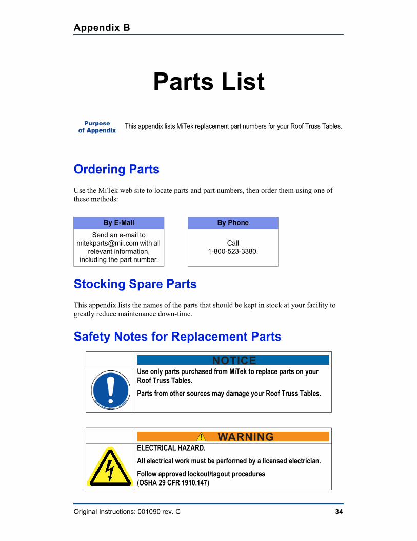
Appendix B
Original Instructions: 001090 rev. C 34
Parts List
Ordering PartsUse the MiTek web site to locate parts and part numbers, then order them using one of these methods:
Stocking Spare PartsThis appendix lists the names of the parts that should be kept in stock at your facility to greatly reduce maintenance down-time.
Safety Notes for Replacement Parts
Purpose of Appendix This appendix lists MiTek replacement part numbers for your Roof Truss Tables.
By E-Mail By Phone
Send an e-mail to [email protected] with all
relevant information, including the part number.
Call1-800-523-3380.
NOTICEUse only parts purchased from MiTek to replace parts on your Roof Truss Tables. Parts from other sources may damage your Roof Truss Tables.
! WARNINGELECTRICAL HAZARD.All electrical work must be performed by a licensed electrician. Follow approved lockout/tagout procedures(OSHA 29 CFR 1910.147)
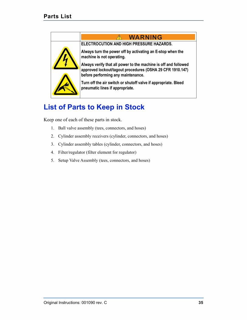
Parts List
Original Instructions: 001090 rev. C 35
List of Parts to Keep in StockKeep one of each of these parts in stock.
1. Ball valve assembly (tees, connectors, and hoses)
2. Cylinder assembly receivers (cylinder, connectors, and hoses)
3. Cylinder assembly tables (cylinder, connectors, and hoses)
4. Filter/regulator (filter element for regulator)
5. Setup Valve Assembly (tees, connectors, and hoses)
! WARNING ELECTROCUTION AND HIGH PRESSURE HAZARDS.
Always turn the power off by activating an E-stop when the machine is not operating.Always verify that all power to the machine is off and followed approved lockout/tagout procedures (OSHA 29 CFR 1910.147) before performing any maintenance.Turn off the air switch or shutoff valve if appropriate. Bleed pneumatic lines if appropriate.
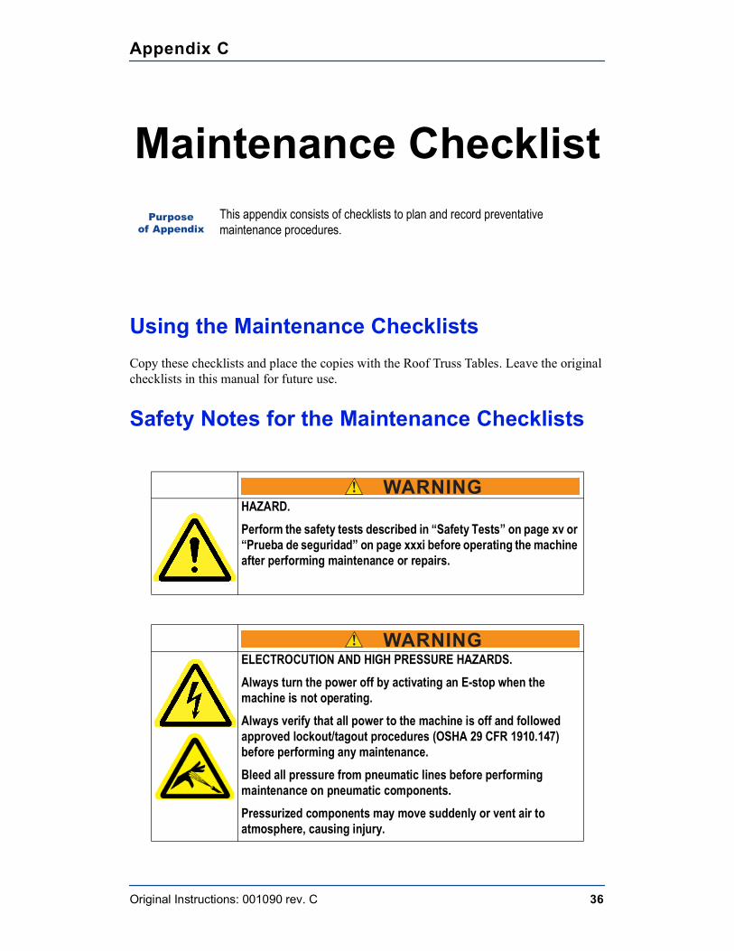
Appendix C
Original Instructions: 001090 rev. C 36
Maintenance Checklist
Using the Maintenance ChecklistsCopy these checklists and place the copies with the Roof Truss Tables. Leave the original checklists in this manual for future use.
Safety Notes for the Maintenance Checklists
Purpose of Appendix
This appendix consists of checklists to plan and record preventative maintenance procedures.
! WARNINGHAZARD.Perform the safety tests described in “Safety Tests” on page xv or “Prueba de seguridad” on page xxxi before operating the machine after performing maintenance or repairs.
! WARNING ELECTROCUTION AND HIGH PRESSURE HAZARDS.
Always turn the power off by activating an E-stop when the machine is not operating.Always verify that all power to the machine is off and followed approved lockout/tagout procedures (OSHA 29 CFR 1910.147) before performing any maintenance.Bleed all pressure from pneumatic lines before performing maintenance on pneumatic components.Pressurized components may move suddenly or vent air to atmosphere, causing injury.
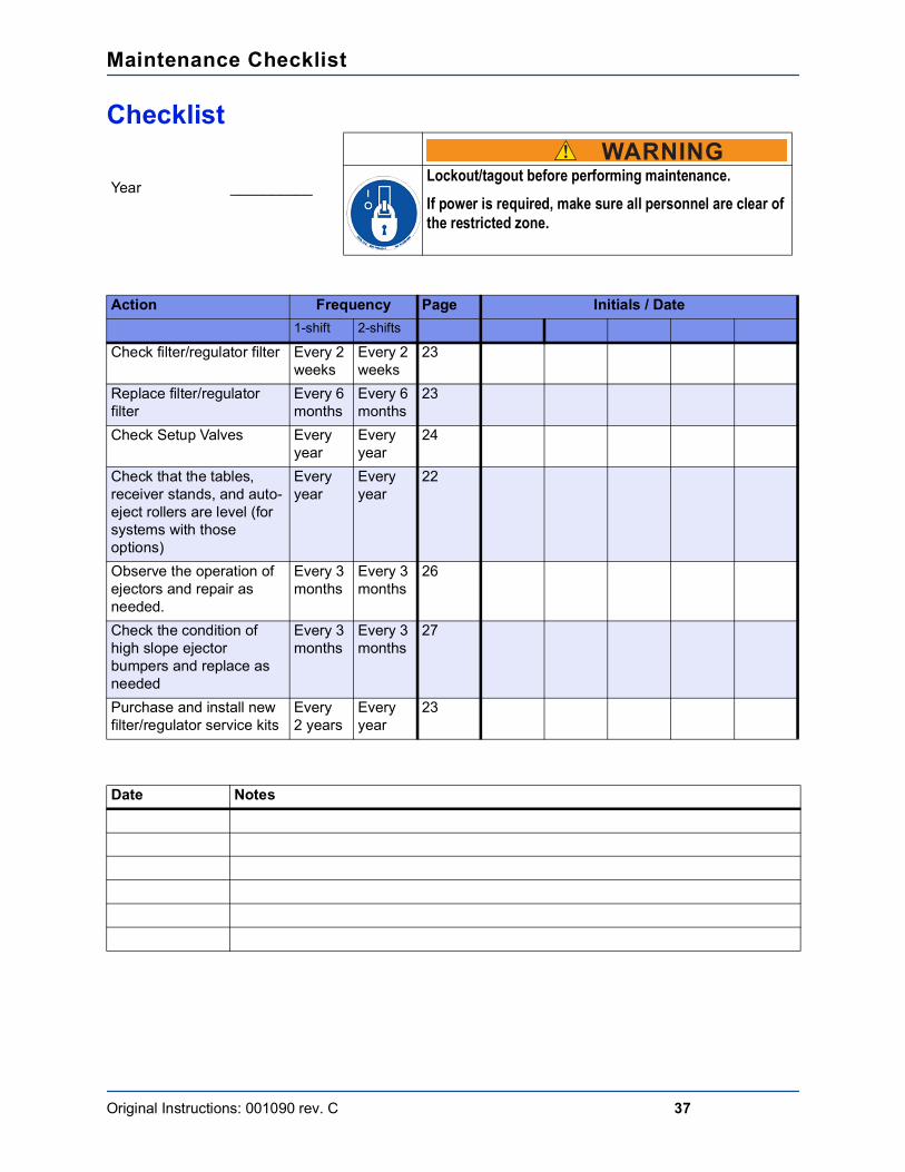
Maintenance Checklist
Original Instructions: 001090 rev. C 37
Checklist
Year __________
Action Frequency Page Initials / Date1-shift 2-shifts
Check filter/regulator filter Every 2 weeks
Every 2 weeks
23
Replace filter/regulator filter
Every 6 months
Every 6 months
23
Check Setup Valves Every year
Every year
24
Check that the tables, receiver stands, and auto-eject rollers are level (for systems with those options)
Everyyear
Everyyear
22
Observe the operation of ejectors and repair as needed.
Every 3 months
Every 3 months
26
Check the condition of high slope ejector bumpers and replace as needed
Every 3 months
Every 3 months
27
Purchase and install new filter/regulator service kits
Every2 years
Everyyear
23
Date Notes
! WARNINGLockout/tagout before performing maintenance. If power is required, make sure all personnel are clear of the restricted zone.
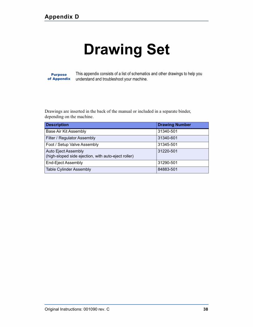
Appendix D
Original Instructions: 001090 rev. C 38
Drawing Set
Drawings are inserted in the back of the manual or included in a separate binder, depending on the machine.
Purpose of Appendix
This appendix consists of a list of schematics and other drawings to help you understand and troubleshoot your machine.
Description Drawing NumberBase Air Kit Assembly 31340-501Filter / Regulator Assembly 31340-601Foot / Setup Valve Assembly 31345-501Auto Eject Assembly (high-sloped side ejection, with auto-eject roller)
31220-501
End-Eject Assembly 31290-501Table Cylinder Assembly 84883-501
Appendix E
Original Instructions: 001090 rev. C 39
Document Evaluation
MiTek Machinery Division makes a continuous effort to provide customers with helpful, accurate documentation.
Please complete this form to provide us with comments or suggestions that improve the quality of our documentation.
Purpose of Appendix This appendix provides a form so that you may evaluate this manual.
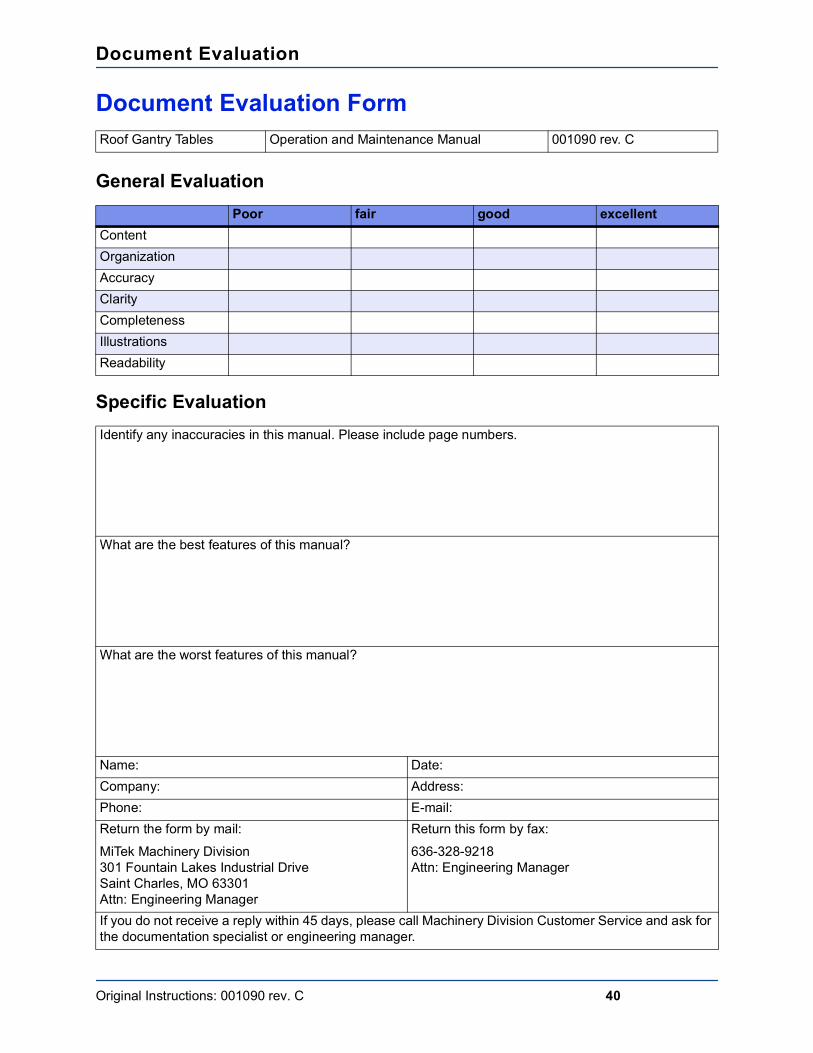
Document Evaluation
Original Instructions: 001090 rev. C 40
Document Evaluation Form
General Evaluation
Specific Evaluation
Roof Gantry Tables Operation and Maintenance Manual 001090 rev. C
Poor fair good excellentContentOrganizationAccuracyClarityCompletenessIllustrationsReadability
Identify any inaccuracies in this manual. Please include page numbers.
What are the best features of this manual?
What are the worst features of this manual?
Name: Date:Company: Address:Phone: E-mail:Return the form by mail:MiTek Machinery Division301 Fountain Lakes Industrial DriveSaint Charles, MO 63301Attn: Engineering Manager
Return this form by fax:636-328-9218Attn: Engineering Manager
If you do not receive a reply within 45 days, please call Machinery Division Customer Service and ask for the documentation specialist or engineering manager.
Glossary
Original Instructions: 001090 rev. C 41
GlossaryPurpose
of Appendix This appendix provides definitions of terminology that apply to your machine.
actuate to activate, put into actionaffected employee an employee whose job requires him or her to operate or use
a machine or equipment on which servicing or maintenance is being performed under lockout or tagout, or whose job requires him or her to work in an area in which such servicing or maintenance is being performed
aisle pad a type of jigging used when a connector plate needs to be embedded where the table surface gives way to a walk-through aisle
amperage the strength of an electric current, expressed in amperesanchor plate a steel plate that holds the tables in place; it is anchored to
the concrete floor and the tables are welded to itauthorized employee a person who locks out or tags out a machine or equipment
in order to perform servicing or maintenance on that machine or equipment; an affected employee becomes an authorized employee when that employee’s duties include performing servicing or maintenance covered under this section
auto-eject a pneumatic system that raises the truss off the tables and automatically places the truss on the stand-alone conveyors, may work in tandem with an auto-eject roller
beacon a light that displays one of several colors to represent the state of the machine
bus bar an electrical device that allows multiple gantry heads to be used simultaneously
connector plate the nail-plate that is embedded into production material to hold it together
cushion an attribute of a hydraulic cylinder that allows for adjustment of pressure at the end of a stroke
Glossary
Original Instructions: 001090 rev. C 42
end-eject a pneumatic system that raises the truss off the tables and allows the truss to be manually pushed or pulled off the end of the tables; this system requires that the gantry head rolls back over the truss or a device must be installed to raise the gantry head when it is parked
energized connected to an energy source or containing residual or stored energy
energy isolating device a mechanical device that physically prevents the transmission or release of energy, including but not limited to the following: manually operated electrical circuit breaker; a disconnect switch; a manually operated switch by which the conductors of a circuit can be disconnected from all ungrounded supply conductors, and in addition, no circuit can be operated independently; a line valve; a block; and any similar device used to block or isolate energy—push buttons, selector switches, and other control circuit type devices are not energy isolating devices
energy source any source of electrical, mechanical, hydraulic, pneumatic, chemical, thermal, or other energy
foot valve a pneumatic foot valve that operates the setup valve to control the release or cessation of air in each setup; it is located on the bottom-chord end of one table in each setup.
gantry head the entire traveling weldment that houses a roller to embed connector plates
jigging any of several devices used to hold the truss in place on the tables
laser scanner a safety device that monitors a defined area in front of a machine for obstructions, slows the machine when it detects a distant obstruction, and triggers an E-stop when it detects a nearby obstruction
layout a scaled diagram of the location of components and the space that they occupy
leveling screws large cap head screws that thread into the table legs and allow the table height to be adjusted and leveled
light bar a perimeter access guarding device used on some models that uses multiple light beams to detect when something is in the way of the gantry head and stops the machine to prevent injury or damage
lockout device a device that utilizes a positive means such as a lock, either key or combination type, to hold an energy isolating device in the safe position and prevent the energizing of a machine or equipment, including blank flanges and bolted slip blinds; should be standardized within the facility in at least one of the following criteria: color; shape; or size; and additionally, in the case of tagout devices, print and format shall be standardized
Glossary
Original Instructions: 001090 rev. C 43
lockout/tagout a means of isolating a piece of equipment from its energy source so maintenance can safely occur; guidelines provided in OSHA 29 CFR 1910.147
motor end used to indicate which end of the gantry head is being discussed; the end of the gantry head that houses the motor
operator control interface
the method in which the operator controls the machine; it may be a touch screen, a control panel, etc.
outer side refers to the end of the gantry head housing; the side farthest from the tables; both ends have an outer side—one can see the outer side of the one end when standing at the pendant control station
pilot valve see hand valve plate see connector platePLC (programmable logic controller) a solid-state control device
that can be programmed to control process or machine operations. It consists of five basic components: processor, memory, input/output module, the power supply, and the programming device.
port a connection point for a peripheral devicepotentiometer a control knob that is a dial; allows a range of values to be
set by turning the dial, commonly found on the PLCproximity switch a switch that uses an electromagnetic field to detect when an
object is near, there is no physical contact between the object and the switch; inductive proximity switches detect only metal objects, capacitive proximity switches can sense both metallic and non-metallic objects
puck a type of jigging that is small and roundqualified person a person or persons who, by possession of a recognized
degree or certificate of professional training, or who, by extensive knowledge, training, or experience, has successfully demonstrated the ability to solve problems relating to the subject matter and work—ANSI B30.2-1983; one who has skills and knowledge related to the construction and operation of the electrical equipment and installations and has received safety training on the hazards involved—NEC2002 Handbook
receiver bar the light bar that receives the signal from the transmitter bar; every light bar set consists of a receiver bar and a transmitter bar
regulator a component of the pneumatic system that connects to the main air source and regulates the air pressure allowed into the system
roller the large roller inside the gantry head that innately embeds the plates into the truss
Glossary
Original Instructions: 001090 rev. C 44
scanner see laser scannerhand valve a pneumatic valve that operates the setup valve to control
the release or cessation of air in each setup; it is located on the bottom-chord end of one table in each setup.
setup valve a component of the pneumatic system that control the flow of air to the rest of the setup, controlled by the hand valve
shut-off valve a valve in the setup valve assembly that controls air flow to all tables in a setup
slider pad a type of jigging used when a connector plate needs to be embedded where the table surface gives way to a slot for the ejector
solenoid an assembly used as a switch consisting of a coil and a metal core free to slide along the coil axis under the influence of the magnetic field
stand-alone conveyor the conveyor system that carries the truss from the tables to the Finish Roller and out to the stacker
stop a type of jigging that is long and straighttagout device a prominent warning device, such as a tag and a means of
attachment, which can be securely fastened to an energy isolating device in accordance with an established procedure, to indicate that the energy isolating device and the equipment being controlled may not be operated until the tagout device is removed; should be standardized within the facility in at least one of the following criteria: color; shape; or size; and additionally, in the case of tagout devices, print and format shall be standardized
take-up bearing adjusts the height of the rollertorque a turning or twisting forceauto-eject roller a motorized roller sitting perpendicular to the tables on an
auto-eject system; it automatically transfers the truss from the Ejectors to the stand-alone conveyors
transmitter bar the light bar that transmits the signal to the receiver bar; every light bar set consists of a receiver bar and a transmitter bar
VFD (variable frequency drive) controls the speed of a cyclevoltage Equal to the difference of electric potential between two
point on a conducting wire carrying a constant current of one ampere when the power between the points is one watt
Appendix G
Original Instructions: 001090 rev. C 45
Aair hose
troubleshooting 33air pressure, adjusting regulator 23
Cchecklists
maintenance 36weekly checklist 37
controls see operator controlscorrections iicushion valves see pneumatic systemcustomer service 4cylinders
cushion valves 26flow control valves 27
Ddocument evaluation 40
Eejectors
troubleshooting 33e-mail support see customer serviceemergency stop see E-stoperrors iiE-stop 13evaluation of document 40
Ffilter/regulator 23
replacement 23flow control valves see pneumatic system
Ggraphics 6
Llockout/tagout
electrical procedure xii, xiiipneumatic procedure xivpneumatic system 22procedure xxviiisymbol 18
lubricator 22
MMachinery Division Customer Service 4
maintenancechecklists 36safety 17
manualintroduction 1navigation 3purpose 1, 2
manual evaluation see document evaluationmarking restricted zone 10
Ooil, lubricator 22operating procedure 15operation
quick start procedure 15stopping 13
operator controls 13
Pparts list 34phone support see customer servicepilot valve, see setup pilot valve 25pneumatic system
air leak 33cylinders
cushion valves 26flow control valves 27
filter/regulatormaintenance 23
lubricator, maintenance 22maintenance 22, 23removing pressure 22system pressure, adjusting 23troubleshooting 33
purpose of manual 1, 2
Rreceivers
troubleshooting 33replacement parts see parts listrestricted zone xvi, 10return goods ii
Ssafety
conformity xxiduring troubleshooting 29general rules viii
IndexPurpose
of Appendix This appendix consists of an index to assist in navigating the manual.

Index
Original Instructions: 001090 rev. C 46
indicators viilockout/tagout ximarking restricted zone xvirestricted zone xvisafety test xxxisignal words viisymbols xviitests xvtroubleshooting with energy xiv
safety signs see safety symbolssetup
troubleshooting 33setup pilot valve 25spare parts see parts liststop motion see E-stopsupport see customer service