Embed Size (px)
Citation preview

Ron Hopkinson Rear Anti-roll Bar
Front left-hand corner of the spare wheel well showing the three nuts for the mounting bracket. The right-hand is a mirror-image, except a bit more cluttered with the fuel pump (on a rubber bumper), vent tubes and harness.
Left-hand side, taken from under the rear bumper looking forward. Shows the drop-link with black rubber bushes at the top and yellow poly at the bottom.
Right-hand side, showng the bar curving round the bump-rubber.
Page 1 of 76
10 January 2015

Corrosion weakening before breakage of the original drop-links
Snapping of the first replacement drop-links
Second replacement drop-links:
A - as received B - strengthened with weld C - Support washer chamfered to fit over strengthening D - unmodified washer E - modified washer
Page 2 of 76
10 January 2015
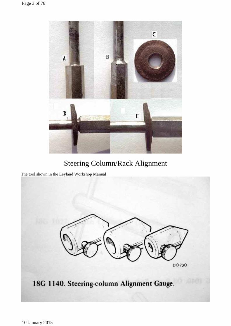
Steering Column/Rack Alignment
The tool shown in the Leyland Workshop Manual
Page 3 of 76
10 January 2015
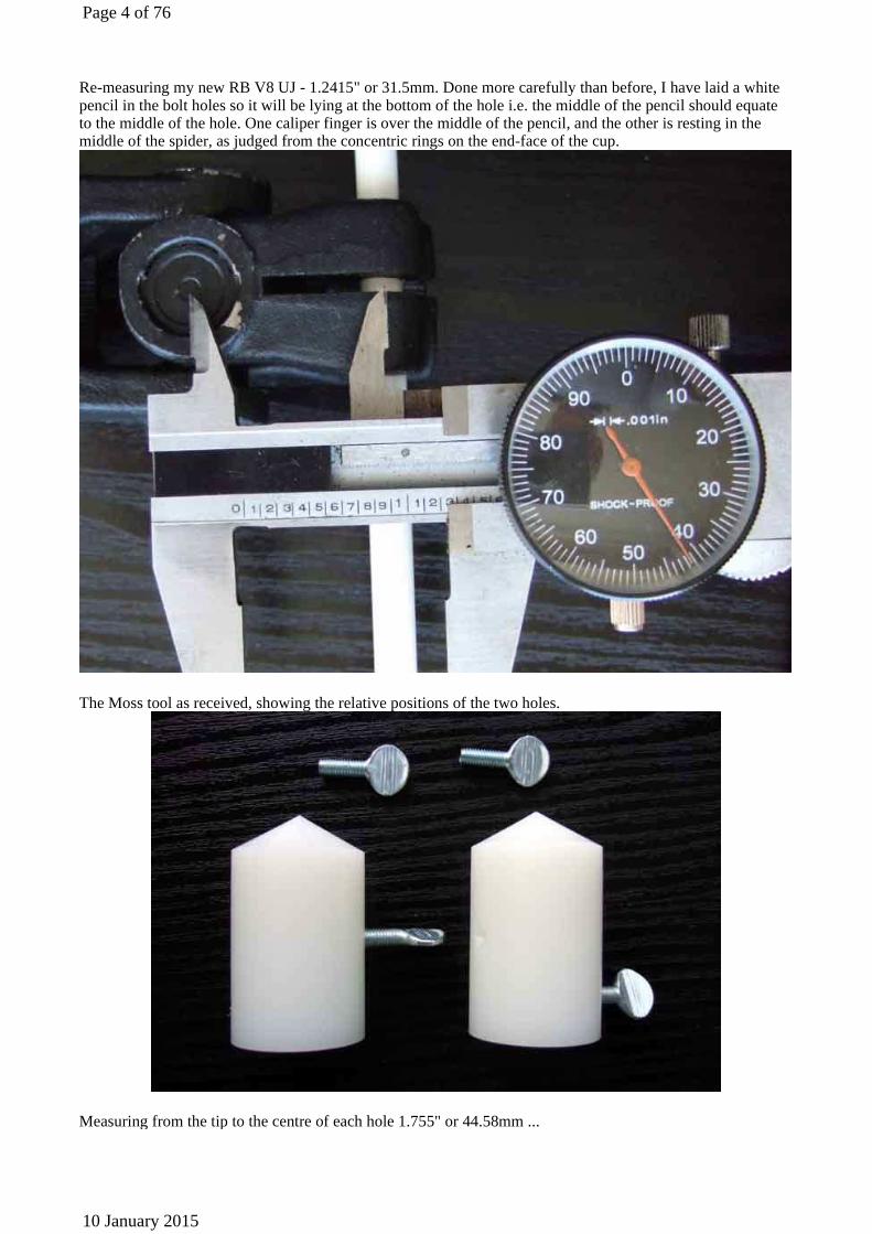
Re-measuring my new RB V8 UJ - 1.2415" or 31.5mm. Done more carefully than before, I have laid a white pencil in the bolt holes so it will be lying at the bottom of the hole i.e. the middle of the pencil should equate to the middle of the hole. One caliper finger is over the middle of the pencil, and the other is resting in the middle of the spider, as judged from the concentric rings on the end-face of the cup.
The Moss tool as received, showing the relative positions of the two holes.
Measuring from the tip to the centre of each hole 1.755" or 44.58mm ...
Page 4 of 76
10 January 2015

... and 1.151" or 29.24mm
Page 5 of 76
10 January 2015

About 1/8" misalignment when checked ...
Page 6 of 76
10 January 2015

... and after correction
Energy-absorbing Steering Column
The non-attached flange at the bottom of the column, shown as part of the assembly in parts lists. Rubber gasket is more or less the same size and shape but is separately quoted. Other people have a rubber sleeve that fits over the end of the column outer, inside the flange. Also not quoted, perhaps part of the assembly like the flange.
Page 7 of 76
10 January 2015

The lower bush, plastic 'washer', spring, steel washer, and circlip that secure the bottom half of the shaft into the column, the sheared 'pins' having allowed the lower part of the shaft to be pushed out of the column.
The plastic sleeve over the collapsible 'mesh' part of the column.
Page 8 of 76
10 January 2015

Stubs of plastic shear 'pin' remaining in the holes of the outer/lower part of the shaft ...
... removed
Page 9 of 76
10 January 2015

Location of ignition switch securing screw (arrowed)
Screw slackened and switch removed
Page 10 of 76
10 January 2015

Circlip retaining the upper bearing in the column. Although removing that allowed the bearing to move up and down I still couldn't withdraw the upper shaft.
Page 11 of 76
10 January 2015

Remains of the injection moulded plastic in the upper half of the shaft ...
... and the 'waisted' section it sits in.
Repaired shaft
Page 12 of 76
10 January 2015

The 'steps' in the shaft, the washer kept getting caught on the bigger one when I tried compressing the spring.
Page 13 of 76
10 January 2015

Box plug spanner neatly fits over the narrowest part of the shaft, and inside the spring and washer, so nullifying the effect of the first, large, step. The smaller step wasn't a problem.
'Keyhole' in plate cut to be slightly bigger than the circlip ...
Page 14 of 76
10 January 2015
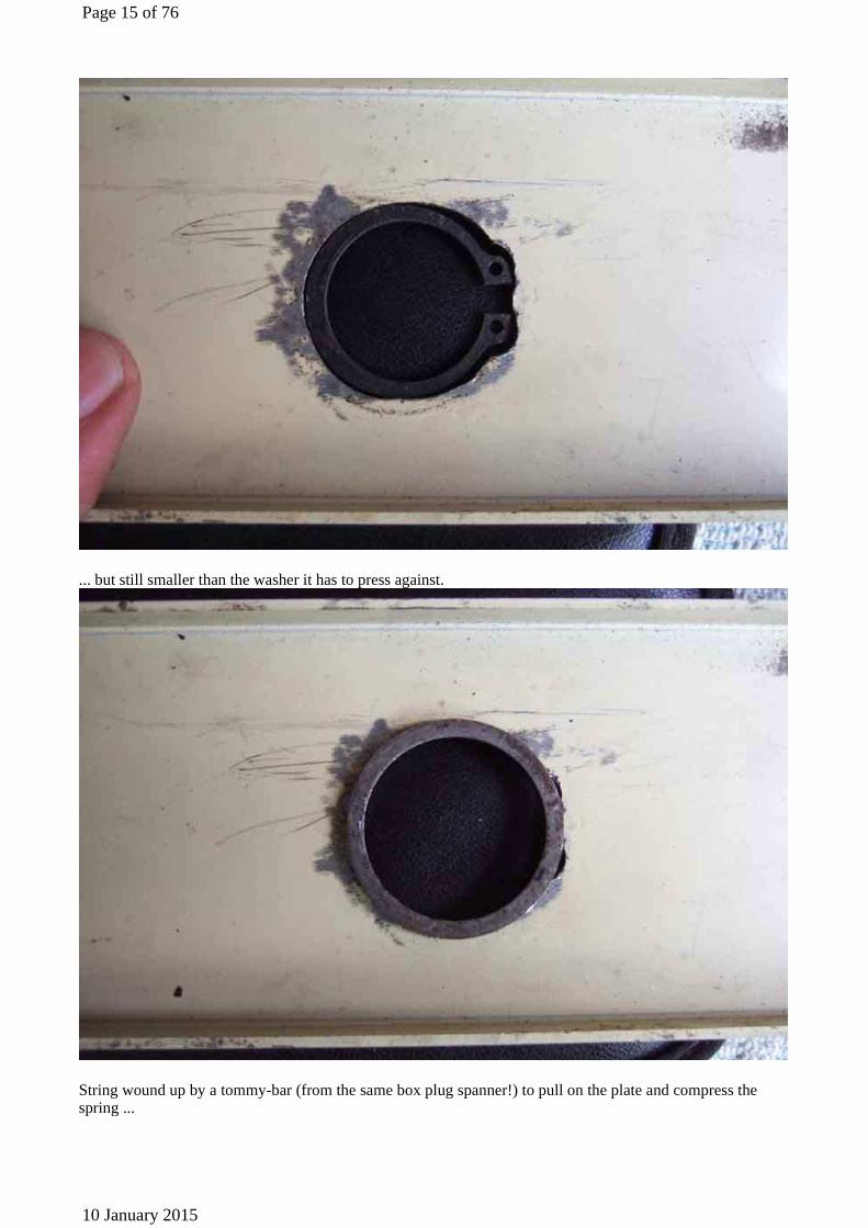
... but still smaller than the washer it has to press against.
String wound up by a tommy-bar (from the same box plug spanner!) to pull on the plate and compress the spring ...
Page 15 of 76
10 January 2015

... the box plug spanner can then be removed ...
... and the circlip fitted!
Page 16 of 76
10 January 2015

Flange, gasket and alignment gauge attached to column before refitting. Subsequently I chose to attach the flange and gasket to the toe-board first, then push the alignment gauge (screw removed) on the end of the shaft through them.
Column aligned.
Page 17 of 76
10 January 2015

Align the tip of the gauge with the centre of the joint, then the hole in the gauge that lines up with the clamp bolt hole is the one to use.
Measurement several times and as careful as I can has shown that the each half of the gauge is a couple of mm shorter from screw to tip than the UJ is from bolt to spider centre, making about 5mm for the two. An orange
Page 18 of 76
10 January 2015

pencil in the UJ bolt hole is lined up with the gauge screw ...
... but the tip is short of the centre of the spider, shown by the concentric rings. This is slightly concerning as this column shaft can't slide up and down inside the outer, the outer has to be bolted to the body brackets to give the correct distance between the cut-outs in the two shafts. In the event, I can get the clamp bolts in the UJ and the rack bolts back into the cross-member brackets, so all was well.
Page 19 of 76
10 January 2015

Note the column shaft has a notch for UJ clamp bolt meaning the UJ can be attached to it in only one rotational position ...
... and the rack shaft is the same! This means that you can only correct steering wheel alignment by a combination of the position of the wheel on the shaft and the relative positions of the track-rod ends on the track-rods. By comparison the roadster rack shaft is grooved all the way round, meaning that can be used to correct alignment (or get it wrong ...) as well.
Page 20 of 76
10 January 2015

Steering Column Universal Joint
Holding the UJ in one hand and striking the indicated point with a hammer knocks the cup out a bit at a time. Using grips to twist it out the rest of the way was surprisingly difficult giving how easy it was to knock it out. If you are replacing the UJ you can knock it out all the way, but if refitting it be ready to catch it, or do it over a clean surface. Shown installed here, but with the circlip removed strike it at the indicated point, holding the UJ in the other hand. Don't strike it near the edges of the hole the cup sits in as you could distort it.
Page 21 of 76
10 January 2015
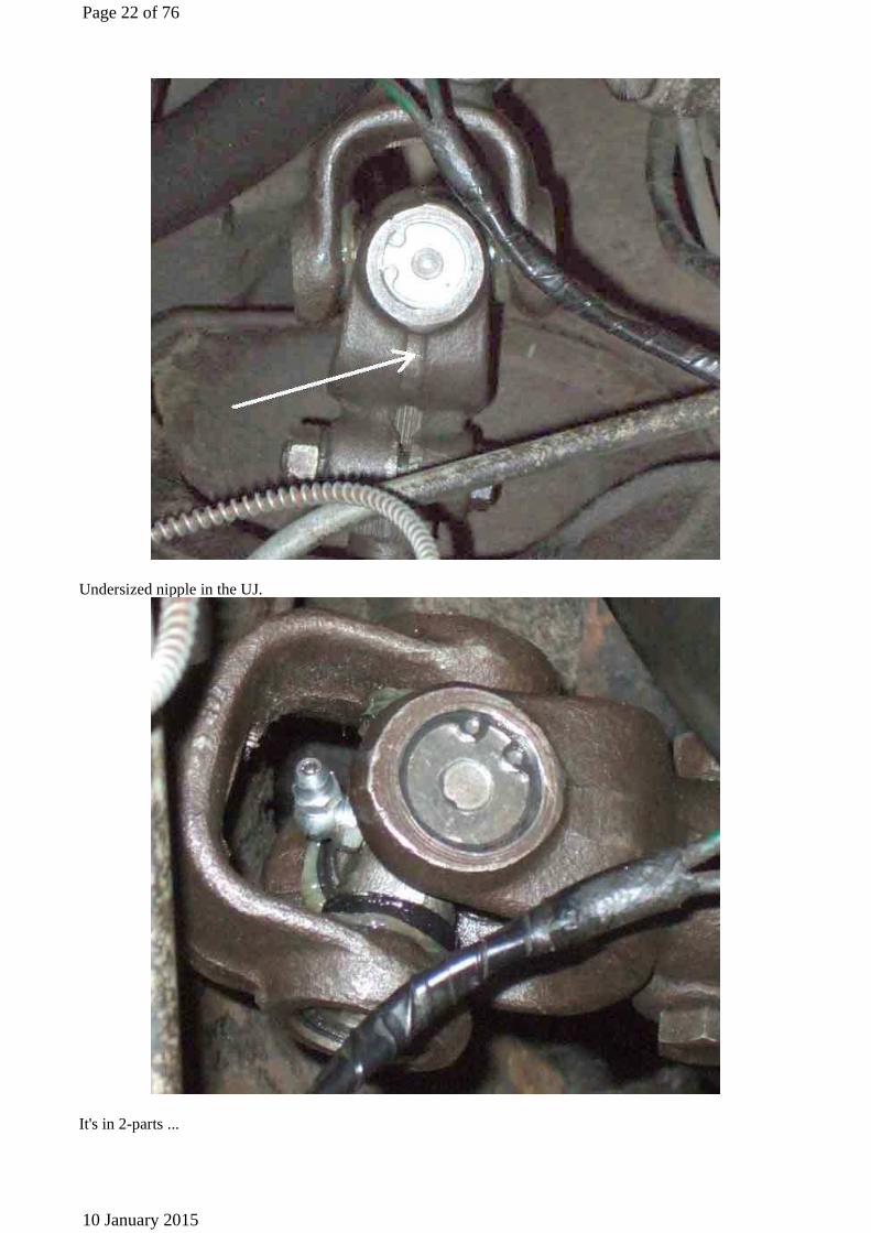
Undersized nipple in the UJ.
It's in 2-parts ...
Page 22 of 76
10 January 2015

... so the nipple proper can be unscrewed leaving the base thread pointing straight up.
Undersized (top) and standard (bottom) nipples, with a drilled adapter stud screwed in to the latter.
Page 23 of 76
10 January 2015

Adapter screwed into the nipple body on the UJ. No ball and spring seal on this as it is only fitted for greasing, the undersized nipple is refitted for normal use.
Page 24 of 76
10 January 2015

Front Hubs Oil seal (circled) correctly fitted with the flat side facing outwards (to the right) and the lip and groove facing inwards
Page 25 of 76
10 January 2015

Front Bump/rebound Rubbers
Bump rubber missing of the bottom of its bracket, spotted when working on the king-pin
Page 26 of 76
10 January 2015

Old and new bump/rebound brackets, notice how the bottom part of the old one is bowed downwards from the swelling of the alloy spacer.
Old and new alloy spacers
Page 27 of 76
10 January 2015

New bracket partially fitted with long lower bolts, needs manipulating to get the upper holes to line up
Showing how the cross-member mounting point has been bowed by the swelling of the old spacer
Page 28 of 76
10 January 2015

Front Damper Replacement Special top link-pin and low-profile castellated nut. For some time the kit containing this pin and the bushes had a totally unsuitable Nyloc nut where the end of the bolt barely reached the nylon insert, let alone had three threads clear. I wouldn't use a Nyloc here anyway, it's holding your front wheel up! The Leacy repair kit:
Hub supported. Either behind the bump/rebound bracket, or the anti rollbar drop-link if replacing the bracket at the same time (note the missing bump rubber!).
Page 29 of 76
10 January 2015

Nut and bolt squeezing the bushes into the trunnion, daub with Waxoyl (note the king-pin is inboard of the trunnion) ...
... but still needed a paint scraper used as a guide to wedge the bushes between the arms (old damper as photo taken on a previous king-pin job) ...
... which were also wedged apart, clamp-bolt slackened right off.
Page 30 of 76
10 January 2015

Front Springs
Bee now with the A-arms and steering arms (latter not visible) angled slightly downwards.
Comparison (left to right) of original roadster springs, used CB GT springs removed from the roadster,
Page 31 of 76
10 January 2015

probably original springs removed from the V8, and new springs waiting to go into the V8. Note that the 2nd, 3rd and 4th items are all the same part. The original roadster springs free height seems hardly to have changed at all, much less than the GT springs from the roadster in only 10 years and 27k miles. Note also that not only are the new springs considerably higher than spec, to the tune of nearly half an inch, but the very old ones removed from the V8 are also slightly higher than spec, which really doesn't seem right. And despite there being little more than a third of an inch difference in free heights between the old and new V8 springs, the difference on the car after a shakedown run was nearly an inch.
King-pins New phospher bronze thrust washer and three selective sizes of shim. At least that is what the numbers stamped into the shims purport to be, five of the six I got from Moss were all the smallest size!
Page 32 of 76
10 January 2015

The recess in the king-pin for the bushes ...
Page 33 of 76
10 January 2015

... and the cut-out in the trunnion (shown with the threaded part of the king-pin in the cut-out for clarity).
Ironically I laid in a top-link repair kit for the side I hadn't had apart before, but didn't need it (for that ...). The Leacy repair kit. Ironically the 'original' (i.e. I hadn't had it off before) top trunnion pin came out easily with just a bit of tapping (on the threaded end of the pin with a lump-hammer behind the opposite damper arm).
Just as well as the pin I'd replaced a few years earlier (which also came out just fine) stripped its thread when re-tightening the nut!
Page 34 of 76
10 January 2015

Hub supported. Either behind the bump/rebound bracket, or the anti rollbar drop-link if replacing the bracket at the same time (note the missing bump rubber!).
A plain nut and/or a spacer makes life easier when trial-fitting shims (not so much doing up and undoing) and protects the Nyloc (on my king-pins, not castellated) insert from wearing out.
Page 35 of 76
10 January 2015

Nut and bolt squeezing the bushes into the trunnion, daub with Waxoyl. Note the king-pin hole is inboard of the bushes and pin ...
... the Leyland Parts Catalogue and Workshop Manual exploded drawings are incorrect ...
Page 36 of 76
10 January 2015

... however the Workshop Manual assembled drawing (mirror-image for comparison with the above drawing) is correct.
Damper cross-bolt slackened, arms wedged apart ...
Page 37 of 76
10 January 2015

... and a paint scraper used as a guide to wedge the bushes between the arms. Again daub the faces of the bushes with Waxoyl, have the king-pin slack at this point so you can turn the trunnion a bit to get one face in, then push on the trunnion and the other face will slide along the paint scraper in to position.
Page 38 of 76
10 January 2015

Swivel Axle Lubrication Two straight nipples (52) in the swivel axle (49), and an angled one (61) in the king-pin. However rather than the two straight ones being the same length as indicated here ... (Image from Leyland Workshop Manual)
... the lower one is longer as shown here. Also shown is the two-part assembly of some angled nipples, although it appears that some might have the straight part pressed into the angled part.
Page 39 of 76
10 January 2015

Ball-joint Splitter
The Sykes-Pickavant ball joint separator as modified. The bolt has to be screwed in so far for the MGB ball joints that it starts making an angle with the lower arm it is bearing on. Despite its heavy construction I could feel the bending forces building up and feared it might shatter, just inches from my face. So I built-up the end of the lower arm so that as the bolt was screwed in, and due to the angles involved moves slightly down the arm from the hinge, its business end is always pretty close to a right-angle with the bit of the arm it is bearing on.
V8 Rear Spring Change
Page 40 of 76
10 January 2015

Right rear wheel way back in the arch ...
... compared to the left rear.
Broken main leaf, the gap showing the other leaves and hence the axle has slipped back by about an inch.
Page 41 of 76
10 January 2015

Rear shackle almost fully extended backwards, but at least it prevented the axle moving back any further and hitting the back of the arch, with who knows what damage.
Page 42 of 76
10 January 2015

Broken spring removed from the car showing the gap between the broken halves and how the spring has slipped through the clips.
New (left) and old shackle bushes, showing the very much thicker flange (and increased overall length) of the new item.
Page 43 of 76
10 January 2015

Shackle squeezed in a small sash cramp before the lock-washers could be fitted and nuts started.
Page 44 of 76
10 January 2015

Springs fully fitted and weight on the wheels, showing a decent curve in the rebound strap, and about 3 1/2" between the top of the bump-stop pedestal and the bump-rubber.
Page 45 of 76
10 January 2015

Even with rubber bumper V8 springs, which are the hardest on any MGB, the shackle is still pointing backwards slightly.
Page 46 of 76
10 January 2015

Comparing nearly new rubber bumper roadster springs with old V8. Front eyes lined up at one end ....
Page 47 of 76
10 January 2015

... shows the 'eye to eye' length about 1/2" longer on the old V8 spring (right).
This is caused by the shape of the old V8 spring having become slightly triangular rather than a smooth curve (V8 spring behind) ...
Page 48 of 76
10 January 2015

... as well as having lost about 1/2" of free arch. Still, surprisingly little change for what are almost certainly original springs having done 197,000 miles.
Another Spring Replacement
Main leaf cracked in a very similar position to Vees
Use a thin, flat cutting disc, not the thicker grinding disc with the offset mounting flange, these came from Halfords.
Page 49 of 76
10 January 2015

Main leaf cut through as close as possible to the eye, then a thin cutting disc up the sides of the eye cuts through the bolt and ends of the spacer tube, just clear of the sides of the bracket. The little ring is what is left of the end of the spacer tube at the bolt head end.
The thread side of the eye, with a flap of the rubber bush and end of the spacer tube that side left attached, the tube only seizing along the plain shank part of the bolt, which is a snug fit in the tube, and not the slightly narrower thread which extends into the tube that end.
Page 50 of 76
10 January 2015

Steering Lock Replacement
New lock
Page 51 of 76
10 January 2015

A - post that operates the switch; B - keyway for key on switch; C - rubber cover for switch; D - Key number; E - Shear-bolts; F - Lock bolt; G - location boss around bolt.
Page 52 of 76
10 January 2015

Drill up into the old shear bolt shanks (new lock pictured for clarity)
Parting the multi-way connector with outside circlip pliers, to get the indicator switch harness out of the way
Page 53 of 76
10 January 2015

Remove the switch
Old lock removed, I'd managed to drill right up the middle of one bolt and only slightly off to one side of the other.
Page 54 of 76
10 January 2015

When fitting the upper part of the lock clamp, the hole A seems to be positioned on the key-side of the fixing holes. Whether this is important or not I don't know.
When fitting the switch back into the new lock, having the clamp loose so the lock hangs down (gaps at A) makes it easier to access the switch fixing screw (B). There is a circular hole in the column outer tube (C) and a corresponding boss around the bolt in the lock body, to ensure correct positioning.
Page 55 of 76
10 January 2015

A lesson in Safety
This article is a reminder of how the safety regulations for motor sport do matter, and are the difference between life and death under extreme circumstances. If you drive a car and don't check your equipment after reading this, you've missed the point.
The Incident
I have been medical officer and then Chief Medical Officer for the M.G. Car Club meeting at Silverstone for some years now, so when I heard the "chequered flag" over the radio from race control for the last race of the Sunday meeting, I sighed with relief and sent my son, James, away to sit in the car. I would be out soon, and it was a tight schedule to get to the NEC, Birmingham, for 7.30. It had been another long boring day, with minor injuries and headaches, that sort of thing. Indeed, in about 2000 race starts at Silverstone in M.G. Car Club meetings in the last 9 years, there had been no significant driver injury.
I was sorting out the paperwork in the medical centre a few seconds later when the scramble call arrived, and James saw me disappear without a word in a green flash. We stopped at Brooklands and got clearance to enter the circuit while cars were still at speed, and then radio silence was called from Race Control to clear the air for a serious incident - which makes Silverstone seriously spooky when you are used to listening to circuit radio, calls from marshalls, cars being snatched and so on. Just a little hiss from the radio as the medical car leans around Luffield. We passed some cars on the grass but no injuries, and then on the exit of Woodcote, half way along the start grid, is the other medical car, the rescue unit and a cluster of people around a wreck.
The intensity of the moment as you arrive at such a scene is hard to describe. Especially if you are responsible. There is a heartsink and fear that there is something will happen over which you will have no control. I am always scared that someone will die and I can't help. A wheel is detached from the car, the tyre unmarked but the alloy bent right out of shape. There is hardly anyone in the grandstand. The drivers face is rather blue, his helmet half off and the anaesthetist, Emmett, is cradling his neck and airway. You notice irrelevant details, such as the shredding of the fibreglass front end or the car where it has been torn. The chest moves normally as the driver breathes and I can't feel any injury, so haemothorax is unlikely. I do not fancy putting in a chest drain on the trackside, however many times I've done it before in hospital. The abdomen is soft and there is no mass over the spleen. By now we have a pulse of 140 and oxygen saturation of 96%. Emmett is clearing some blood away from the mouth with suction, but the airway is safe. The pulse is still strong. We can relax a bit as there seems no desperate problem apart from the head and neck, so we can concentrate on getting him out of the car slowly and without risking any injury to his neck or back. As he cannot speak to us, we must treat as though there is a spinal injury.
We slow down and take it carefully, and the team is co-ordinated by myself and we pool all our skills, especially the paramedics who are experienced in extrication. There is a chance to look around more, but all I really see is the RAC steward with a notebook, writing down what we are doing. The deliberation at this stage appears painfully slow to outsiders. Why are they not doing it faster? But it is hard to get someone out of a car under these circumstances. Space is more cramped than you expect, overalls get snagged in the footwell, and so on. Pulling him out too fast would only cause injury. The paramedics are very experienced at extrication and work to position a backboard, and, of course, a neck brace is already on. The cutters snip off the steering column, and then the roll cage. Out he came, and I nipped back quickly to the medical centre by car as the
Page 56 of 76
10 January 2015

other two doctors came in the ambulance. The nurses in the centre have cleared out anyone with cuts and bruises, and the bed in the resuscitation area was ready with chest drain kit, oxygen, cardiac monitoring and so on all to hand. I brief them on what to expect.
We decide not to move him off the ambulance trolley, as he will be going to hospital soon He is starting to wake up, and is rather restless. It was good that he was partially awake and answering some questions, but when he started intermittently thrashing around from cerebral irritation it made us feel we had less control. We checked the pulse and oximetry a third time, and they were getting even better. Chest, abdomen, arm and leg examination confirm no serious injuries, so it is best to get him in the ambulance and off to Northampton General Hospital as soon as possible. I telephone the hospital, warning them what to expect. Then a telephone call to his wife and talk to his friends, sort out the paperwork and report to Race Control. Finally, my bemused son was still in the car! More telephone calls and a dash to the NEC just in time for my daughter’s trip to All Saints. We just missed a rather poor backing band but were in time for the main act. By the way chaps, they may not look too bad, but they can't sing.
The video
Before I left Silverstone, Race Control showed me the video of Russ's crash - by now I knew his name. He had been overtaking round the outside of another driver, both taking a fairly tight line because of a third car. There was contact and Russ went right over into the concrete wall, with no chance to slow down. He hit the concrete at just too acute an angle to bounce off along the track, so the car just crumpled a little and came back a couple of yards. The remarkable feature was the close up of the cockpit area. The car stopped so abruptly that the deceleration forces were clearly incredible. The harness stretched right out, so that his chest hit the steering wheel, and his head flew forwards but did not hit any fixed object. Debris missed him entirely, but anyone sitting on the left hand side of the car would have risked crush and penetrating injuries at chest, neck and head level. As I watched the impact over and again, the enormity of the forces experienced by Russ's body became more and more apparent.
Laws of physics
Russ is an example of the effects of pure deceleration forces that were marginally sublethal. I refer to my copy of "The Pathology of Violent Injury" here. The G forces (multiples of the force of gravity) experienced during this type of event are calculated by G = 0.0039v2/d, where v is the speed in km/h and d is the distance over which the deceleration occurs, in metres. The MGB did not deform much during the abrupt hC deceleration - this saved his legs from external crush, but the lack of crumple increased the forces on Russ because the distance over which deceleration occurred was shorter Let's say the speed was 120 km/h and the M.G. had 0.75 metre of crush as it stopped, both I think reasonable estimates (Russ estimated his speed rather faster, I think, at about 140 km/h, but we'll be more conservative here). Therefore the deceleration was just under 75G. This represents a potentially fatal injury - at much over 60G, either the heart ruptures or the aorta falls off the heart. Russ's feet were up against the footwell and decelerated at the same rate as the rest of the car, and indeed Russ has fractures of bones in one foot. Recall, the footwell was not deformed and there was no intrusion . It was purely the force of the weight of his foot against the footwell that caused the fractures. If Russ's body had decelerated at this rate, he would have died from multiple injuries. Why was he saved?
The harness, you remember, stretched out forwards so that his torso moved over some distance - perhaps a bit too far as the steering wheel was bent, but the deceleration was spread over almost another metre. This gets the deceleration down to below 40G, which is survivable for the human torso. Then his head - this flew forwards another half a metre, so that the G was force was down to under 20G. However, the stretch on the neck must have transiently been much greater than this, as the neck would offer little resistance to forward movement until it got right forward. If the terminal deceleration on the neck was about 25G, then the force on the neck was twenty five times the weight of the head plus the helmet. This injury, I think, made Russ unconscious. The top of his brain was squashed against the inside of his skull and his brain stem, lower down, was stretched. All this occurred momentarily before the whiplash. You can see why the brain gets scrambled, even if it swims around in a little pool of cerebrospinal fluid, cushioning impacts. It is likely that some of the nerve-to-nerve contacts (synapses) rupture or are disrupted during the impact, and the severity and extent of this disruption determine the extent of brain injury. The brain can look normal to the naked eye, but becomes unwired. Russ was unconscious for about 10 minutes, not so bad as some other well known drivers - Mika Hakkinen had a much worse brain injury in Australia in 1985, but, as with Russ, there seems to be no lasting cerebral injury.
Page 57 of 76
10 January 2015

The safety message
Russ's survival in this impact was down to perhaps the most mundane article of safety, which most of us take for granted. The safety harness is a brilliantly engineered piece of kit that converts a lethal injury into graded deceleration and survivable impact. So make sure your harness is not old and has not been stretched in an accident before - they don't stretch twice. Make sure your mounting points are secure - if Russ decelerated at 25G and it was probably greater, the shoulder mounts would have taken a force of over half a ton each. Indeed, examination of Russ's car apparently showed the metal around these mounts was deformed, but had not given way. Russ commented to me that in his MGA, the mounting points would probably have given way - so think about strengthening your harness mounting points, and spreading the load area. When you buy a helmet, get one that is strong and light - a heavy helmet can be bad news, so invest well. Make sure your seat is firmly attached to the floor - you don't want that on your back.
Lastly, if you have a six point harness, do arrange the crotch straps carefully when you strap yourself in. If your pelvis weighs 20kg and you decelerate at 25G, you've dropped half a ton in the area of your testicles, so your eyes might water.
Other accidents at Silverstone
Yes, this accident looked a little like that sustained by Michael Schumacher, and the rescue team followed exactly the same types of procedure (I was not at
Silverstone for the Grand Prix). But the Ferrari hit the concrete at 100 km/h, apparently , and the deceleration was not enough to make Schumacher lose consciousness. Russ hit the wall harder, and was fortunate enough to have a car that, in this type of impact, looked just as strong. Amazing little cars, M.G.s, aren't they?
Thanks to the team The paramedic, rescue, marshalling nursing teams and everyone else involved at Silverstone were wonderful; their experience and training made the rescue effective, controlled and state of the art. Although I was Chief Medical Officer, I had to do virtually nothing, the entire team worked like clockwork and they must take the credit. I do not think they could have been better, so if you are going to have a bump like Russ anywhere, Silverstone is the place Even better, drive safely and look after yourselves.
Refurbing a steering wheel for Vee
As received. Scruffy, but an undamaged rim ...
Page 58 of 76
10 January 2015

... although wire-brushing marks on the spokes ...
Page 59 of 76
10 January 2015

... and rust on the back
Hub needs repainting. Rubbing with wire wool dipped in cellulose thinners got all the old paint off and left a smooth surface. Hammerite special metals primer as the first coat, then two coats of Hammerite smoothrite satin black.
Page 60 of 76
10 January 2015

Horn push pretty-well perfect
Page 61 of 76
10 January 2015

Dismantled ready for refurb
One spoke polished up
Page 62 of 76
10 January 2015

Horn button dismantled ...
... and the brass and copper contacts cleaned up
Page 63 of 76
10 January 2015

Slip-ring dismantled ...
... the wire replacing the pencil soldered on ...
Page 64 of 76
10 January 2015

... and attached to the horn push. This will need removing from the horn push to be fitted through the hole in the hub. Make sure the tag or whetever you use fits through the hole. You could use a bullet conenctor in the wire, or a spade connector screwed to the back of the horn button, but how often are you going to be removing it? Make sure the whatever you do screw to the back of the horn push clears the copper ring on the alloy base of the push, or the horn will sound continuously ...
Fitted, and at long last I can see the supplementary gauges with a glance instead of having to peer round the rim, as well as having lighter steering. Gold-highlighted logo as befits a 1975 build.
Page 65 of 76
10 January 2015

Track-rod Ends and Tracking Alignment
Bee's old and new track-rod ends of different lengths.
Page 66 of 76
10 January 2015

Badly worn unit.
Page 67 of 76
10 January 2015

Vee's track-rod ends: Angle-ground along the body of the track-rod to just expose the threads. A bit of a 'do or die' treatment, you wouldn't want to drive it having done this. If this hadn't worked I would have had to remove the rack with track-rod end attached and take it somewhere to get some heat on it.
Ring-spanner on the end of the Stillsons to give more leverage
Page 68 of 76
10 January 2015

Double lock-nuts which I can lock together to make turning the track-rod easier, although judging by the other side I'll not have a problem with it again. If doing this make sure you fully tighten the first lock-nut against the end of the track-rod end, then just lightly nip the second nut up to that. If you just lock the two nuts together the track-rod end could be loose on the track-rod (although highly unlikely to come unscrewed from it).
Page 69 of 76
10 January 2015

Toe in, dimension A being at the front of the car and less than dimension B.
The reference measurement taken from behind the wheel
Page 70 of 76
10 January 2015

Rolling the car forward half a wheel turn.
The comparison measurement taken in front of the wheel at the same marks as before.
Page 71 of 76
10 January 2015

Tracking gauge
Page 72 of 76
10 January 2015

Going Back to Lever-arm dampers
Page 73 of 76
10 January 2015
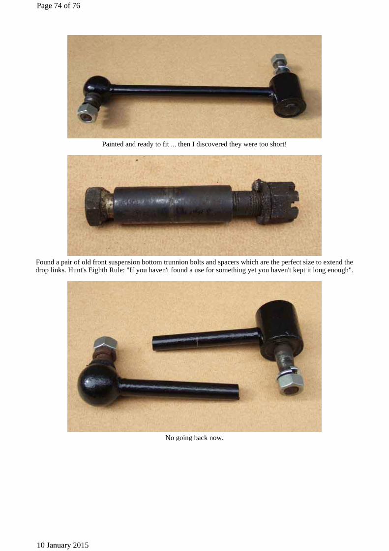
Painted and ready to fit ... then I discovered they were too short!
Found a pair of old front suspension bottom trunnion bolts and spacers which are the perfect size to extend the drop links. Hunt's Eighth Rule: "If you haven't found a use for something yet you haven't kept it long enough".
No going back now.
Page 74 of 76
10 January 2015

Ready for welding, showing how the spacer can be used to sleeve both welds for additional strength.
Detail of cut and shaped ends to be filled with weld.
Welded and flattened ready for repainting.
Page 75 of 76
10 January 2015

Ready to fit, I decided to rely on my welding for a neater result. However shortly after fitting one of the welds
did break, so I did fit a sleeve when repairing that. The other sleeved one has been fine ... so far.
© Copyright 1999 to 2015 I.T. Answers. http://www.mgb-stuff.org.uk/
Page 76 of 76
10 January 2015