Embed Size (px)
Citation preview
Product Manual - RoLP LX Wall Base VAD Range
M12-003 Issue A 08/03/13
Page 1 of 22
Product Manual
RoLP LX Wall Base VAD Range
Cooper Fulleon Ltd Llantarnam Park
Cwmbran South Wales NP44 3AW
+44 (0)1633 628500 www.fulleon.co.uk
Product Manual - RoLP LX Wall Base VAD Range
M12-003 Issue A 08/03/13
Page 2 of 22
Contents Title Page INTRODUCTION 3
GENERAL FUNCTIONAL DESCRIPTION 3
Coverage Volume 4, 5
Current Consumption Data 6, 7
Installation Guidance & Advise 18
General Safety Advise 18
Maintaining IP ratings – Good Practice 18
Typical Wiring Configuration 19
Power Supplies & Control Panels 19
Wiring 20
Typical Wiring Calculations 20
Maintenance Advice 21
Annex A: Document Change Summary 22
Referenced Documents Title Doc. Ref. Installation Guide (included with product) 25-11204
Product Manual - RoLP LX Wall Base VAD Range
M12-003 Issue A 08/03/13
Page 3 of 22
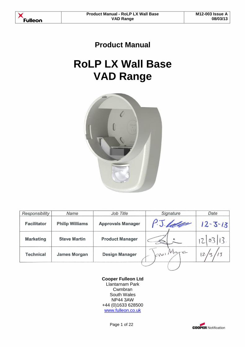
Introduction The Roshni LP, or RoLP LX Wall Base is a range of high specification VADs (Visual Alarm Devices) suitable for wall mounting in accordance with EN54-23. They are compatible with a number of sounder devices from the Roshni range, and are used in place of the standard shallow, deep or U base. They are suitable for visual alarm signalling within open areas or corridors and passages. The device has been specifically designed for use within fire alarm systems, to meet the requirements of the CPR (Construction Products Regulation). It produces a flash of light at a predetermined interval when connected to a suitable power supply. When connected to a common power supply, devices will self-synchronise their flashing for a defined period of time after starting (see installation guide for more detail). Connection is via a screw terminal connector block for ease of termination of cables. Each connection has a terminal for looping in and out. The device is fixed to a suitable location using a choice of either a shallow, deep or ‘U’ bayonet mounting base.
General Functional Description The device is normally in an off state, with no voltage applied to the power terminals. In this state, the device has no power and so does not operate. When the device is required to operate, a voltage between 9 - 60VDC is applied to the appropriate power terminals. This provides power to the circuit via a polarity protection / system monitoring diode, & an RC network which provides supply smoothing and noise immunity protection. Further protection is also provided against voltage spikes on the supply. At the heart of the device is a microprocessor which derives its power from a switched mode voltage regulator circuit. Clock timing and device synchronisation is provided via the oscillator clock drive crystal & associated capacitor network. The light flash is achieved by the use of an LED (Light Emitting Diode). A drive circuit generates the necessary voltage & current required to drive the LED. Control of the flash is achieved via the microcontroller, which runs the programmed firmware for its operation.
Notes:
See installation guide for details on technical specifications, connection instructions & mounting arrangements.
Product Manual - RoLP LX Wall Base VAD Range
M12-003 Issue A 08/03/13
Page 4 of 22
Coverage Ratings VAD performance is now stated as an actual ‘real world’ coverage volume, rather than the old misleading & often inconsistent figures of point intensity (candela), circuit power (watts) or flash storage energy (joules). As a result, achieving a more relevant & consistent performance is now more straight forward, since the actual coverage volume, area & distance of the VAD in an installation is stated. Below are the coverage ratings for the range: - RoLP LX Wall Base (White Flash) Power Setting
(High/Low)
Flash Rate Setting
(Hz)
Width of Square Room y (at mounting height x=2.4m)
(m)
Floor Coverage
Area
(m2)
Coverage Volume
(m3)
Current Consumption
@ 24VDC
(mA)
High 1 7.5 56.25 135 25
Low 1 2.5 6.25 15 15.5
High 0.5 7.5 56.25 135 15.5
Low 0.5 2.5 6.25 15 9.5
RoLP LX Wall (Chromaplus Flash) Power Setting
(High/Low)
Flash Rate Setting
(Hz)
Width of Square Room y (at mounting height x=2.4m)
(m)
Floor Coverage
Area
(m2)
Coverage Volume
(m3)
Current Consumption
@ 24VDC
(mA)
High 1 7.5 56.25 135 37
Low 1 2.5 6.25 15 21.1
High 0.5 7.5 56.25 135 23.2
Low 0.5 2.5 6.25 15 13.2
RoLP LX Wall Base (Red Flash) Power Setting
(High/Low)
Flash Rate Setting
(Hz)
Width of Square Room y (at mounting height x=2.4m)
(m)
Floor Coverage
Area
(m2)
Coverage Volume
(m3)
Current Consumption
@ 24VDC
(mA)
High 1 2.7 7.3 17.5 24.5
Low 1 Not EN54-23 14.5
High 0.5 2.7 7.3 17.5 14.5
Low 0.5 Not EN54-23 10.5
The designators x & y are defined in EN54-23, and define the coverage volume of the VAD. NOTE: For more information, see overleaf for an overview of the designators, or for more detailed information please refer to EN54-23 (EU) & COP 0001 (UK only).
Product Manual - RoLP LX Wall Base VAD Range
M12-003 Issue A 08/03/13
Page 5 of 22
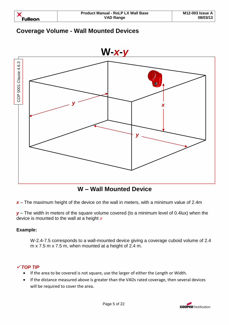
Coverage Volume - Wall Mounted Devices
W-x-y
W – Wall Mounted Device
x – The maximum height of the device on the wall in meters, with a minimum value of 2.4m y – The width in meters of the square volume covered (to a minimum level of 0.4lux) when the device is mounted to the wall at a height x
Example:
W-2.4-7.5 corresponds to a wall-mounted device giving a coverage cuboid volume of 2.4 m x 7.5 m x 7.5 m, when mounted at a height of 2.4 m.
TOP TIP
If the area to be covered is not square, use the larger of either the Length or Width.
If the distance measured above is greater than the VADs rated coverage, then several devices
will be required to cover the area.
CO
P 0
001 C
lause 4
.6.3
y
y x
Product Manual - RoLP LX Wall Base VAD Range
M12-003 Issue A 08/03/13
Page 6 of 22
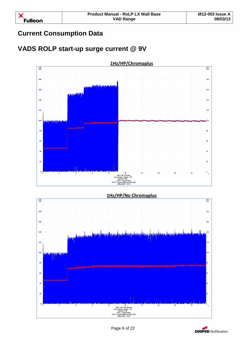
Current Consumption Data VADS ROLP start-up surge current @ 9V
1Hz/HP/Chromaplus
1Hz/HP/No Chromaplus
Product Manual - RoLP LX Wall Base VAD Range
M12-003 Issue A 08/03/13
Page 7 of 22
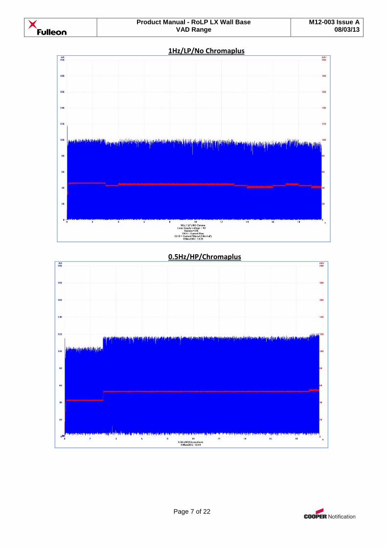
1Hz/LP/No Chromaplus
0.5Hz/HP/Chromaplus
Product Manual - RoLP LX Wall Base VAD Range
M12-003 Issue A 08/03/13
Page 8 of 22
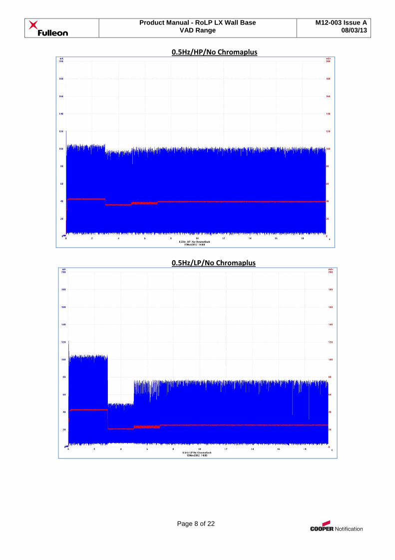
0.5Hz/HP/No Chromaplus
0.5Hz/LP/No Chromaplus
Product Manual - RoLP LX Wall Base VAD Range
M12-003 Issue A 08/03/13
Page 9 of 22
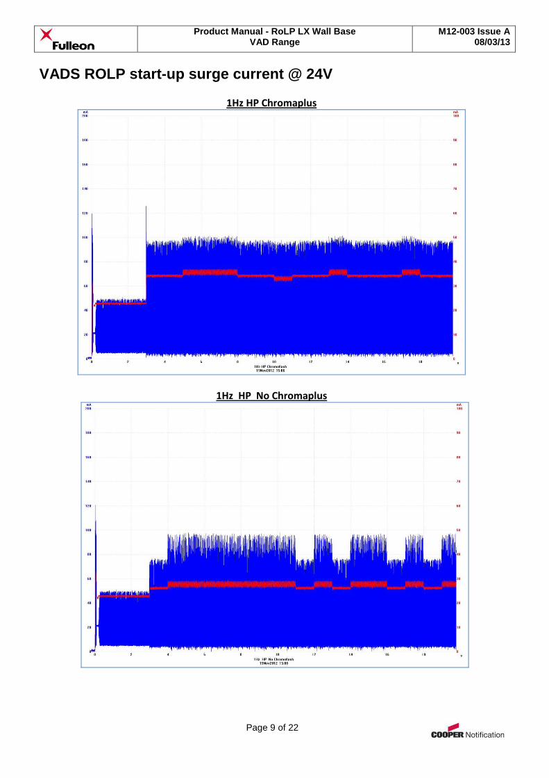
VADS ROLP start-up surge current @ 24V
1Hz HP Chromaplus
1Hz HP No Chromaplus
Product Manual - RoLP LX Wall Base VAD Range
M12-003 Issue A 08/03/13
Page 10 of 22
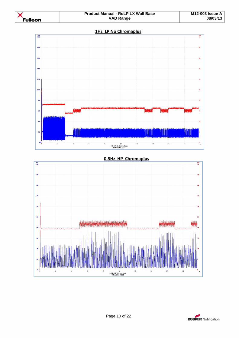
1Hz LP No Chromaplus
0.5Hz HP Chromaplus
Product Manual - RoLP LX Wall Base VAD Range
M12-003 Issue A 08/03/13
Page 11 of 22
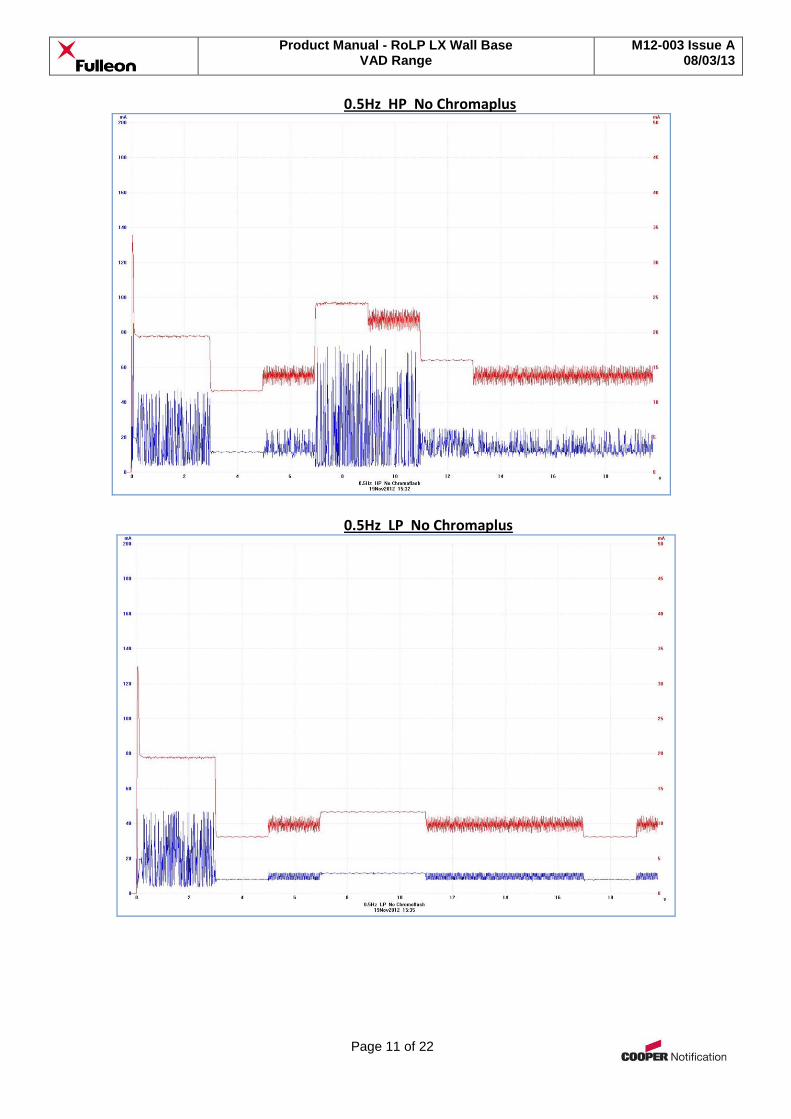
0.5Hz HP No Chromaplus
0.5Hz LP No Chromaplus
Product Manual - RoLP LX Wall Base VAD Range
M12-003 Issue A 08/03/13
Page 12 of 22
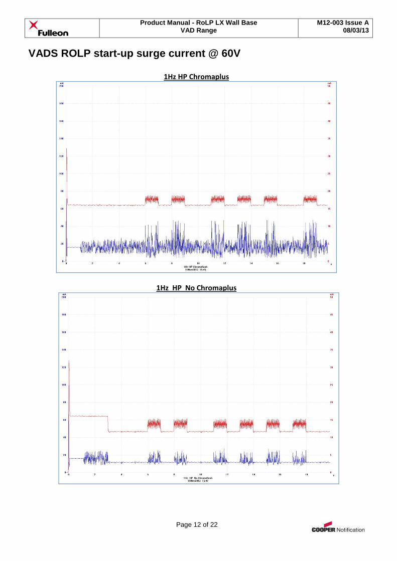
VADS ROLP start-up surge current @ 60V
1Hz HP Chromaplus
1Hz HP No Chromaplus
Product Manual - RoLP LX Wall Base VAD Range
M12-003 Issue A 08/03/13
Page 13 of 22
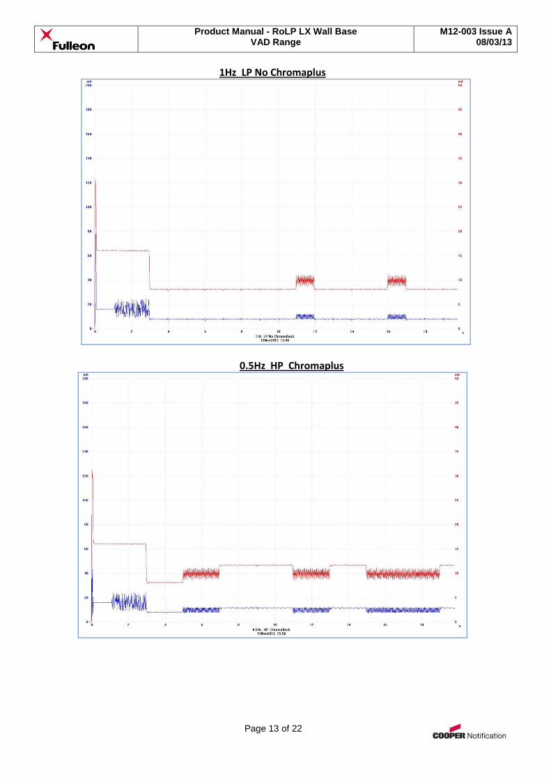
1Hz LP No Chromaplus
0.5Hz HP Chromaplus
Product Manual - RoLP LX Wall Base VAD Range
M12-003 Issue A 08/03/13
Page 14 of 22
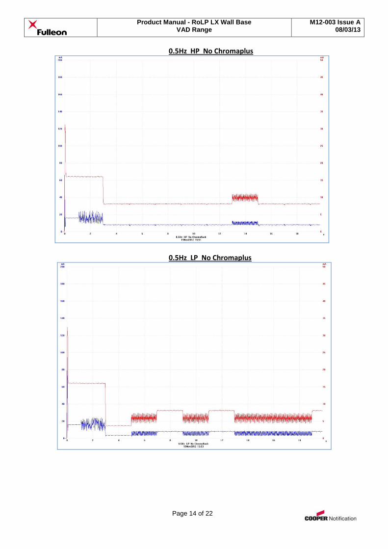
0.5Hz HP No Chromaplus
0.5Hz LP No Chromaplus
Product Manual - RoLP LX Wall Base VAD Range
M12-003 Issue A 08/03/13
Page 15 of 22
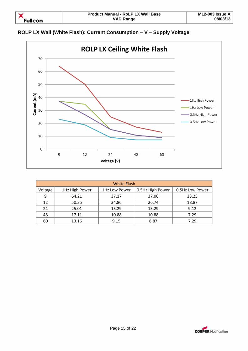
ROLP LX Wall (White Flash): Current Consumption – V – Supply Voltage
White Flash
Voltage 1Hz High Power 1Hz Low Power 0.5Hz High Power 0.5Hz Low Power
9 64.21 37.17 37.06 23.25
12 50.35 34.86 26.74 18.87
24 25.01 15.29 15.29 9.12
48 17.11 10.88 10.88 7.29
60 13.16 9.15 8.87 7.29
Product Manual - RoLP LX Wall Base VAD Range
M12-003 Issue A 08/03/13
Page 16 of 22
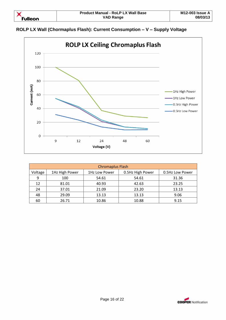
ROLP LX Wall (Chormaplus Flash): Current Consumption – V – Supply Voltage
Chromaplus Flash
Voltage 1Hz High Power 1Hz Low Power 0.5Hz High Power 0.5Hz Low Power
9 100 54.61 54.61 31.36
12 81.01 40.93 42.63 23.25
24 37.01 21.09 23.20 13.13
48 29.09 13.13 13.13 9.06
60 26.71 10.86 10.88 9.15
Product Manual - RoLP LX Wall Base VAD Range
M12-003 Issue A 08/03/13
Page 17 of 22
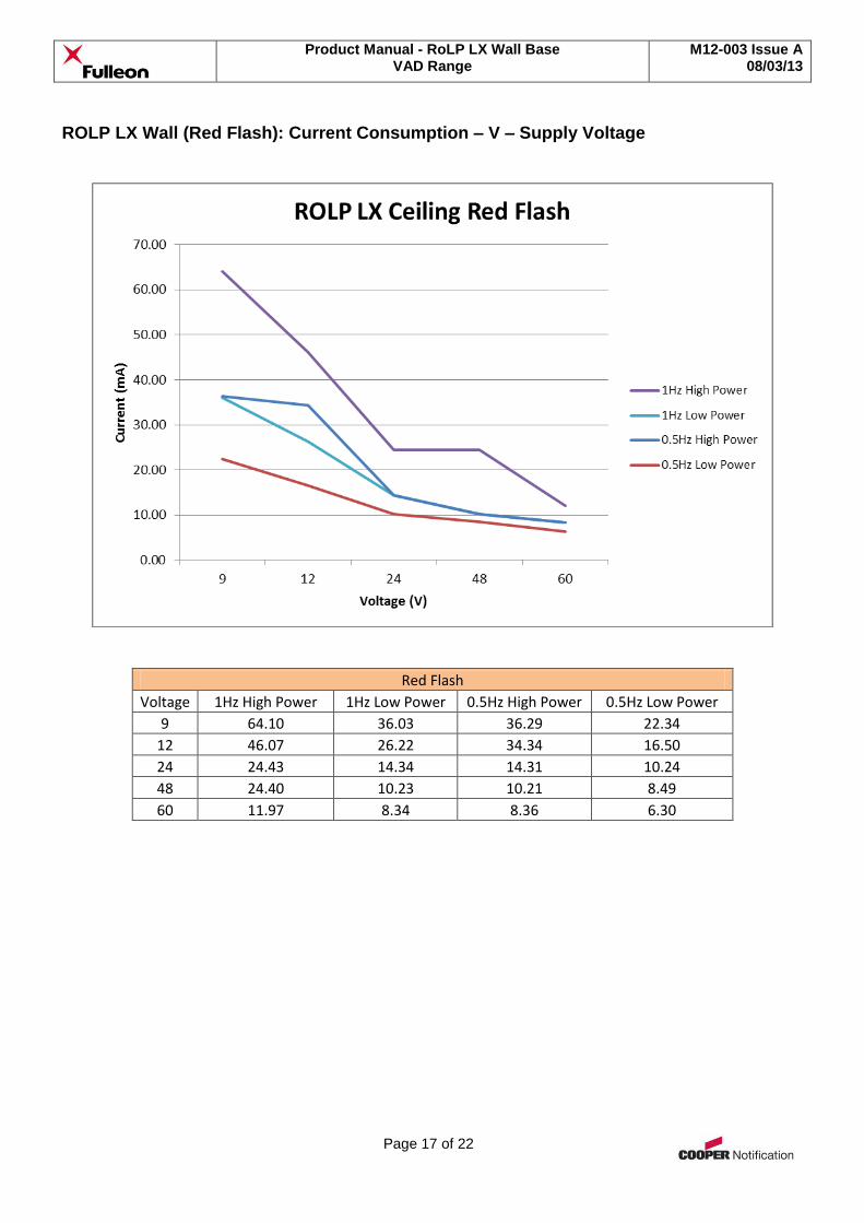
ROLP LX Wall (Red Flash): Current Consumption – V – Supply Voltage
Red Flash
Voltage 1Hz High Power 1Hz Low Power 0.5Hz High Power 0.5Hz Low Power
9 64.10 36.03 36.29 22.34
12 46.07 26.22 34.34 16.50
24 24.43 14.34 14.31 10.24
48 24.40 10.23 10.21 8.49
60 11.97 8.34 8.36 6.30

Product Manual - RoLP LX Wall Base VAD Range
M12-003 Issue A 08/03/13
Page 18 of 22
Installation Guidance & Good Practice
General Safety Guidance
Do not work on live circuits
Follow local wiring regulations where relevant
Ensure that the base is secured to the mounting surface using the most appropriate fixings. Plasterboard and hollow walls will require special anchor fixings.
Maintaining IP (Ingress Protection) ratings – Good Practice
If using the product in a high humidity or damp / wet environment, it is recommended that ONLY a deep or ‘U’ base is used. The deep or ‘U’ base has a higher IP rating than the shallow base and can be used with appropriate cable glands (not included) to achieve the stated IP rating. The shallow base is only intended for INDOOR use, in low humidity environments.
Use suitable cable glands (where appropriate) to maintain the designed IP rating. The stated product rating will ONLY be achieved if the product is installed correctly. A selection of suitable glands is available from all good electrical wholesalers. Always follow the cable gland instructions.
Where conduit systems are used to provide cable protection, consideration should be given to appropriate drainage points, to ensure that any condensation or water droplets forming within the conduit itself are able to safely drain away, without adversely compromising any connected devices.
Ensuring that all base and mounting screws are secure.
Product Manual - RoLP LX Wall Base VAD Range
M12-003 Issue A 08/03/13
Page 19 of 22
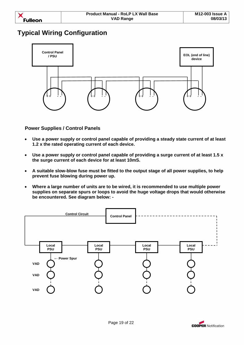
Typical Wiring Configuration
Power Supplies / Control Panels
Use a power supply or control panel capable of providing a steady state current of at least 1.2 x the rated operating current of each device.
Use a power supply or control panel capable of providing a surge current of at least 1.5 x the surge current of each device for at least 10mS.
A suitable slow-blow fuse must be fitted to the output stage of all power supplies, to help prevent fuse blowing during power up.
Where a large number of units are to be wired, it is recommended to use multiple power supplies on separate spurs or loops to avoid the huge voltage drops that would otherwise be encountered. See diagram below: -
EOL (end of line)
device
Control Panel
/ PSU
+ - + - + - + - + - + - + - + -
Control Panel
Local PSU
Local PSU
Local PSU
Local PSU
VAD
VAD
VAD
Control Circuit
← Power Spur
Product Manual - RoLP LX Wall Base VAD Range
M12-003 Issue A 08/03/13
Page 20 of 22
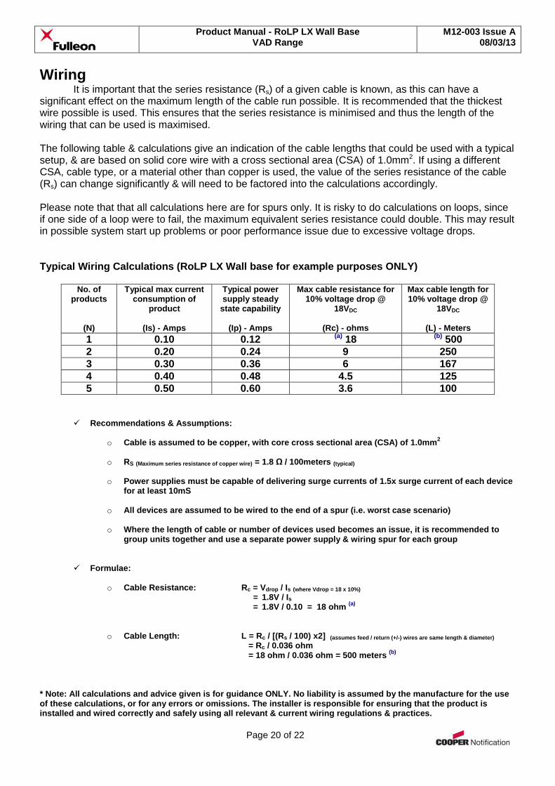
Wiring It is important that the series resistance (Rs) of a given cable is known, as this can have a
significant effect on the maximum length of the cable run possible. It is recommended that the thickest wire possible is used. This ensures that the series resistance is minimised and thus the length of the wiring that can be used is maximised. The following table & calculations give an indication of the cable lengths that could be used with a typical setup, & are based on solid core wire with a cross sectional area (CSA) of 1.0mm2. If using a different CSA, cable type, or a material other than copper is used, the value of the series resistance of the cable (Rs) can change significantly & will need to be factored into the calculations accordingly. Please note that that all calculations here are for spurs only. It is risky to do calculations on loops, since if one side of a loop were to fail, the maximum equivalent series resistance could double. This may result in possible system start up problems or poor performance issue due to excessive voltage drops. Typical Wiring Calculations (RoLP LX Wall base for example purposes ONLY)
No. of products
(N)
Typical max current consumption of
product
(Is) - Amps
Typical power supply steady
state capability
(Ip) - Amps
Max cable resistance for 10% voltage drop @
18VDC
(Rc) - ohms
Max cable length for 10% voltage drop @
18VDC
(L) - Meters
1 0.10 0.12 (a) 18 (b) 500
2 0.20 0.24 9 250
3 0.30 0.36 6 167
4 0.40 0.48 4.5 125
5 0.50 0.60 3.6 100
Recommendations & Assumptions:
o Cable is assumed to be copper, with core cross sectional area (CSA) of 1.0mm2
o RS (Maximum series resistance of copper wire) = 1.8 Ω / 100meters (typical)
o Power supplies must be capable of delivering surge currents of 1.5x surge current of each device
for at least 10mS
o All devices are assumed to be wired to the end of a spur (i.e. worst case scenario)
o Where the length of cable or number of devices used becomes an issue, it is recommended to group units together and use a separate power supply & wiring spur for each group
Formulae:
o Cable Resistance: Rc = Vdrop / Is (where Vdrop = 18 x 10%) = 1.8V / Is = 1.8V / 0.10 = 18 ohm
(a)
o Cable Length: L = Rc / [(Rs / 100) x2] (assumes feed / return (+/-) wires are same length & diameter)
= Rc / 0.036 ohm = 18 ohm / 0.036 ohm = 500 meters
(b)
* Note: All calculations and advice given is for guidance ONLY. No liability is assumed by the manufacture for the use of these calculations, or for any errors or omissions. The installer is responsible for ensuring that the product is installed and wired correctly and safely using all relevant & current wiring regulations & practices.
Product Manual - RoLP LX Wall Base VAD Range
M12-003 Issue A 08/03/13
Page 21 of 22
Maintenance
The product is of a low maintenance design. However, systems should be tested on a regular basis after installation. This is vital where products are used in life safety systems. Please refer to current & relevant maintenance practices.
If the product is installed in a harsh environment, check seals and housing condition for any obvious signs of wear and tear or damage on a periodic basis.
Cleaning of the product housing should be carried out using non-abrasive and non-corrosive substances. A lightly moistened soft cloth is usually sufficient.
Product Manual - RoLP LX Wall Base VAD Range
M12-003 Issue A 08/03/13
Page 22 of 22
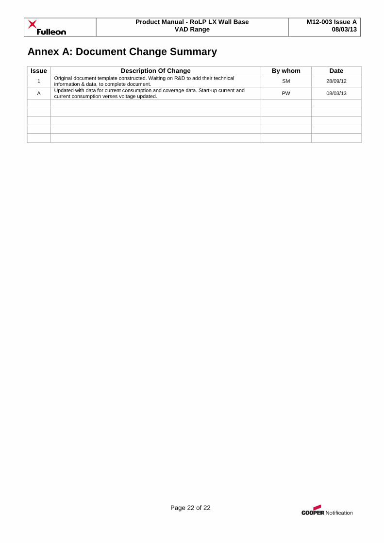
Annex A: Document Change Summary Issue Description Of Change By whom Date
1 Original document template constructed. Waiting on R&D to add their technical information & data, to complete document.
SM 28/09/12
A Updated with data for current consumption and coverage data. Start-up current and current consumption verses voltage updated.
PW 08/03/13