Embed Size (px)
Citation preview
ñ 5- f^^-^ Agriculture Handbook No. 257 ,'Z-
U s DEPT. OF AGRICUI-TURE
CURRENT SWiAw RtCOaOS
ROLLER GINNING
S^ American- ■ Egyptian K Cotton
in the Southwest
Agricultural Research Service
UNITED STATES DEPARTMENT OF AGRICULTURE
Contents
Page Problems in Ginning American-Egyptian Cottons . 2 The Modern Roller Ginning Plant 4 Operation of the McCarthy-type Roller Gin Stand 6 Cleaning Pima Seed Cotton 9
Testing Procedures 12 Hand-picked Undefoliated Cotton 13 Machine-picked Undefoliated Cotton 14
Drying Pima Seed Cotton 19 Static Electricity in Roller Ginning 20 Pneumatic Conveying and Cleaning of Pima Lint 23 Saw Ginning Pima Cotton 27 Summary 28 Literature Cited 29 Appendix 31
Fans and Piping 31 Gin Roller Covering 40 Seed Cotton Reclaimers 43 Mill-type Lint Opener-cleaners 44
Washington, D.C. Issued January 1964
n
Acknowledgments
Acknowledgment is made of the helpful assistance given the author by his fellow workers in assembling this handbook. Special acknowl- edgment is made to Messrs. Charles A. Bennett, deceased, and Wilbur M. Hurst, retired, of the Cotton Ginning Investigations of AES, for their assistance and suggestions.
in
ROLLER GINNING American-Egyptian Cotton
in the Southwest BY DAVID M. ALBERSON and VICTOR L. STEDRONSKY, agricultural engineers, Agri-
cultural Engineering Research Division, Agricultural Research Service *
Since 1950, cleaners, driers, extractors, and pneumatic conveyances have become increasingly important in ginning American-Egyptian cotton grown in the Southwest. Modern harvesting practices and the high price and shortage of labor have necessitated a change in ginning practices on extra long staple cotton. Each year the seed cotton has been arriving at the gin with more foreign matter and a higher moisture content.
Production of American-Egyptian cotton in the United States since 1950 has ranged from a high of 93,500 bales in 1952 to a low of 49,100 bales in 1956 (lo),^ In 1958, 81,900 bales were produced and in 1959, 69,100. The entire American-Egyptian cotton crop is grown in the Salt Kiver Valley of Arizona, in New Mexico, and in District 6 of Texas.
This handbook contains available research data on the eflFects of cleaning, extracting, drying, and pneumatic handling on American- Egyptian cottons grown in the United States. Before 1950, this type of cotton had been ginned with less cleaning and handling by ma- chinery than upland cotton, which requires more careful picking, roller ginning, and packaging.
The U.S. Department of Agriculture conducted limited research between 1926-41 on roller ginning. World War II halted the work and it was not resumed until 1950. Small-scale experiments were con- ducted by the Southwestern Cotton Ginning Research Laboratory at Mesilla Park, N. Mex., during the harvesting seasons of 1950, 1951, and 1952. Intensive investigations were started there in 1953 after facilities for roller ginning research were installed. Representative experiments and their results are reported in this handbook. Addi- tional engineering data and some recent commercial developments are given in the appendix.
^ Headquarters : Southwestern Cotton Ginning Research Laboratory, Mesilla Park, N. Mex.
^ Italic numbers in parentheses refer to Literature Cited, p. 29.
1
PROBLEMS IN GINNING AMERICAN-EGYPTIAN COTTON American-Egyptian cotton was first produced commercially in the
Southwest in 1911 after discovery of a variety that became known as "Yuma." This variety was grown in the Imperial Valley of Cali- fornia and the Salt Eiver Valley of Arizona until 1917 Production rose from 30 bales in 1911 to 15,966 bales in 1917 (7).
Yuma cotton had a staple length of approximately 1%6 inches {16), was very fine, and could not be ginned satisfactorily on a saw gin. Consequently, to retain the qualities required for spinning, Yuma had to be roller ginned and handled by methods similar to those used for sea-island cotton, which had formerly been grown in the South- east for the high-quality cotton market {11). Bennett {3) has re- viewed the history of American-Egyptian cotton in the Southwest and the development of machinery to gin this type of cotton.
With the coming of the boll weevil in the southern cotton States, production of sea-island cotton practically ceased. Many roller gins thus found their way to the Southwest for use in ginning the new long- staple varieties of cotton. Roller ginning at that time usually con- sisted of a simple cleaner feeder with a spiked draper belt that carried a small amount of very clean hand-picked seed cotton to the gin roller {10). If the cotton was trashy, it was usually passed through a 3-cylinder picker-roller cleaner and an inclined shaker before being fed to the roller gin.
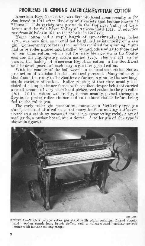
The early roller gin mechanism, known as a McCarthy-type gin stand, consisted of a roller, a stationary knife, a moving knife con- nected to a crank by means of crank legs (connecting rods), a set of seed grids, a pusher board, and a doffer. A roller gin of this type is shown in figure 1.
BN 1840r,
FIGURE 1.—McCarthy-type roller gin stand with plain bearings, forged cranlîs and wooden crank legs, brush doiïer, and a spiral-wound packing-covered roller with leather moting strips.
In 1918, Yuma cotton was replaced commercially by "Pima," which had been discovered as a single plant in a field of Yuma at the U.S. Cotton Field Station, Sacaton, Ariz., in 1910. From 1918 to 1939, Pima or Pima crosses were the only varieties of American-Egyptian cotton grown. More than 92,000 bales of Pima were produced m 1920.
Because of unstable production, gin owners were reluctant to make expenditures on roller gin improvements. However, from 1930 to 1940 some ginners made individual mechanical changes and improve- ments to the older McCarthy-type gin stands. Plain bearings were replaced with ball or roller bearings, gin frames were made more sturdy, and an effort was made to improve mechanical dependability and to achieve more continuous operation.
Production increased substantially in 1941 and 1942. As old equip- ment wore out and no other old gin stands were available for replace- ment, for the first time in several decades new roller gins were manu- factured. American gin machinery manufacturers installed many new gin stands to handle and gin almost 74,000 bales in 1942 and almost 60,000 bales in 1943. But in 1944 the number of bales ginned dropped to 8,600. From 1944 to 1949 the industry was again almost dormant and many gins were idle. During those 6 years, an average of only 3,950 bales was produced annually.
In 1950 production again skyrocketed to 62,200 bales. Acreage in Arizona, New Mexico, and Texas increased greatly, and new ginning plants were constructed in the Salt River Valley of Arizona, in the Mesilla Valley of New Mexico, and in the El Paso Valley and near Pecos, Texas. Production reached an all-time high of 93,500 bales in 1952, only to drop to 64,500 in 1953. In 1954 and 1955 production again dropped to an estimated 40,000 bales annually but increased to 49,100 bales in 1956. In 1957,79,700 bales were grown ; in 1958,81,900 ; in 1959,69,100 ; and in 1960 only 60,000 {16).
It was believed for years that long, fine-fibered Pima cotton must be handled very gently and that ginning was a very delicate operation. Farniers took great care in harvesting clean, hand-picked cotton, and the ginners avoided unnecessary handling. In some cases one or two overhead unit extractor cleaners were added to the 4-cylinder cleaner, all of which received the seed cotton from the wagon suction telescope. After it passed through the separator or dropper and received limited cleaning, the cotton accumulated on the second floor and was then manually pushed to chutes and delivered by gravity to the gin stands beneath. Plants ranged in size from 12 to 36 stands. As the stands ginned the cotton, the lint fell to the floor and was manually pushed to a single-box press for baling.
The gins manufactured in 1942 were modern designs of sturdy steel or cast iron—a marked improvement over the old equipment. Ball and roller bearings or improved lubrication elements made continuous operation more dependable. Eoller and crank speeds were increased to 125 and 900 r.p.m., respectively. However, as the old principles of operation were unchanged, the new gins had only slightly more hourly capacity than the old ones. The new gins were two sizes. One company manufactured a 40-inch roller whereas another increased the length to 54 inches. New roller ginning plants erected in 1942 followed the old pattern of building construction, generally two stories. The gins were on the ground floor, and a separator or pneumatic dropper and usually a 4-cyclinder cleaner Avere installed on the second floor.
In 1952 several new ginning establishments were erected in Arizona, New Mexico, and Texas. One company increased roller length to 60 inches but retained other mechanical features similar to the 54-inch 1942 models. But in 1950 there was a marked change in the building construction of roller ginning plants.
THE MODERN ROLLER GINNING PLANT
Since 1950 the roller ginning plants constructed in the Southwest have included many of the latest design features, similar arrangements of machinery, and the modern equipment used in modem saw gins. The old two-story wooden or brick building has given way to single- floor or li/^-story prefabricated all-steel structures. Installation of the machinery at ground level is convenient for arrangement, change, and maintenance.
Overhead shafts for gin drives have been largely replaced by in- dividual motors at each gin stand. Lint-conveyor belts carry the cotton to an air nozzle pickup and thence to a condenser and a double- box press. Latest types of seed-cotton cleaning and extracting ma- chinery and drying equipment are being used, and each gin stand is fed by a unit feeder cfeaner. Pneumatic seed-cotton conveyance and con- ventional screw-type augers have jointly replaced manual handling.
Many other practices followed in a modern upland-type saw-gin plant are followed in the ginning of American-Egyptian cotton varie- ties. Piping, air-flow, storage, and seed and trash handling require- ments are similar to those that have been reported for saw gins {H).
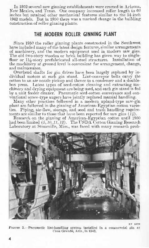
Research on the ginning of American-Egyptian cotton until 1950 had been limited (5,10,11,12). The USDA Cotton Ginning Research Laboratory at Stoneville, Miss., was faced with many research prob-
BX 18406
B^GtjRB 2.—Pneumatic lint-handling system installed in a commercial gin at Casa Grande, Ariz., in 1943.
BN 18399, BN 18402
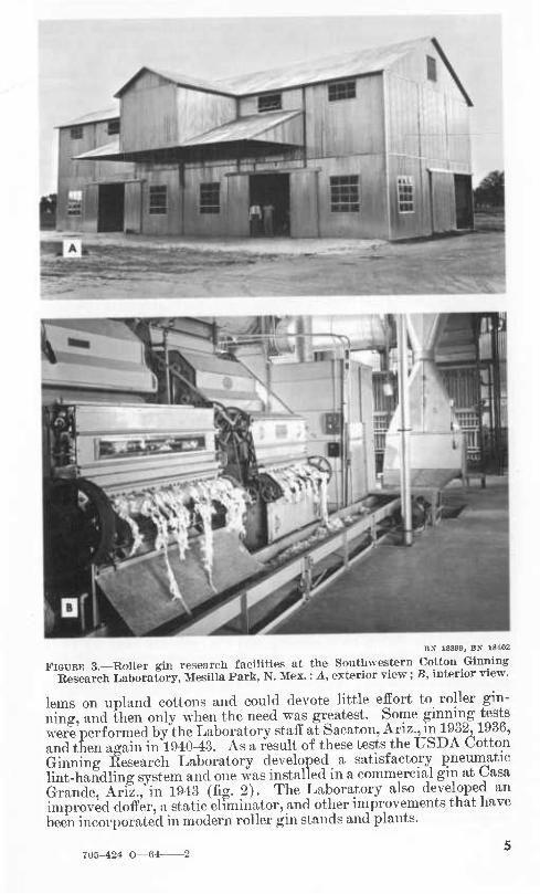
FIGURE 3.—Roller gin research facilities at the Southwestern Cotton Ginning Research Laboratory, Mesilla Park, N. Mex. : A, exterior view ; B, interior new.
lems on upland cottons and could devote little effort to roller gin- ning, and then only when the need was greatest. Some ginning tests were performed by the Laboratory staff at Sacaton, Ariz., m 1932,1936, and then again in 1940-43. As a result of these tests the USDA Cotton Ginning Research Laboratory developed a satisfactory pneumatic lint-handling system and one was installed in a commercial gm at Casa Grande, Ariz., in 1943 (fig. 2). The Laboratory also developed an improved doffer, a static eliminator, and other improvements that have been incorporated in modern roller gin stands and plants.
705-424 0—64-
The Southwestern Cotton Ginning Research Laboratory at Mesilla Park, N. Mex., began roller ginning tests on a limited scale in 1950. In 1953, a roller ginning laboratory building was erected (fig. 3, J.). It is fully equipped with drying, overhead cleaning, and extracting equipment plus a belt-pneumatic lint-handling system, double-box press, and most of the late-model roller gins. Thus, for the first time, facilities and working space were available to start a complete re- search program on roller ginning of American-Egyptian cotton (fig. S^ B), Also, for the first time, Imt-cleaning devices w^ere operated in conjunction with roller gins. This research was prompted by pro- ducers of long-staple cotton, who were being forced to harvest their crops mechanically because of high labor costs. In so doing, unsatis- factory grades were being produced in the existing gins.
OPERATION OF THE McCARTHY-TYPE ROLLER GIN STAND Figure 1 shows a typical McCarthy-type roller gin with plain bear-
ings, forged cranks, and wooden crank legs. This rather crude con- struction has not been conducive to continuous operation because con- stant adjustments and repairs are required. Such gins have operated with roller speeds of approximately 100 r.p.m. and crank speeds of 600 r.p.m. Ginning capacity has been relatively low in the United States—from 1 to li/^ pounds of lint per hour per inch of roller length.
The operation and gin settings of the 1950 model of the McCarthy- type roller gin stand are approximately the same as those of models built up to 1942. The greatest difference is that on the 1950 model these settings are easier to make and maintain. Bearings, eccen- trics, and general gin construction have been improved. However, the settings and adjustments of roller gins vary greatly. Some set- tings and adjustments are based on experience accumulated over years of operating both the old model roller gins and the present gin stands. Others are purely theoretical and are based on engineering knowledge alone. The ultimate goal is the ginning of the greatest amount of cot- ton without undue wear on the gin, while retaining the highest possible fiber quality. Thus the proper setting or adjustment of a roller gin is based on a combination of experience, common sense, and applica- tion of basic or established engineering knowledge.
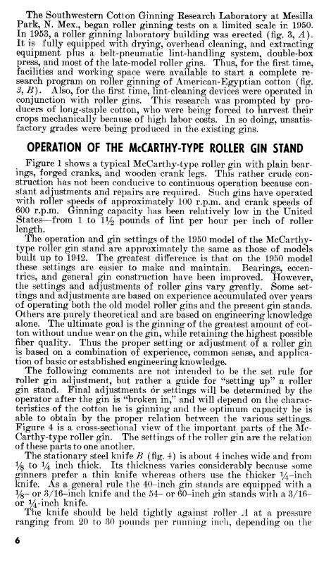
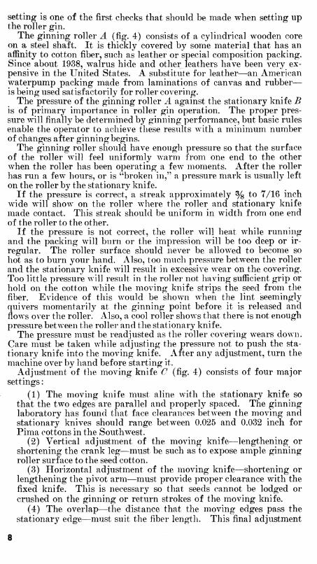
The following comments are not intended to be the set rule for roller gin adjustment, but rather a guide for "setting up" a roller gin stand. Final adjustments or settings will be determined by the operator after the gin is "broken in," and will depend on the charac- teristics of the cotton he is ginning and the optimum capacity he is able to obtain by the proper relation between the various settings. Figure 4 is a cross-sectional view of the important parts of the Mc- Carthy-type roller gin. The settings of the roller gin are the relation of these parts to one another.
The stationary steel knife B (fig. 4) is about 4 inches wide and from Vs to 1/4 inch thick. Its thickness varies considerably because some ginners prefer a thin knife whereas others use the thicker Vi-inch knife. As a general rule the 40-inch gin stands are equipped with a l^- or 3/16-inch knife and the 54- or 60-inch gin stands with a 3/16- or 14-inch knife.
The knife should be held tightly against roller A at a pressure ranging from 20 to 30 pounds per running inch, depending on the
— -o:o^
Diogrom A
Diagram B DioQram C
FIGURE 4.—Conventional features of McCarthy-type roller gin stands, models, 1917 to 1950. DIAGRAM A, typical cross section of upper portion of the unit showing A, ginning roller; B, stationary knife; C, moving knife; D, crank leg: £/, cranks and crankshaft ; F, pivot for moving knife ; O, pusher board ; and H, seed grid. DIAGRAM B, ginning roller, A, and stationary brush doffer, /. DIA- GRAM C, ginning roller, A, and USDA-improved rotary doffer, J.
covering material. The working or bottom edge of the knife should be on or slightly below the center line of the roller. The stationary knife must be so clamped that its ginning edge is in the same plane as the axis of the roller; when set in this manner and when the ginning roller pressure is applied, the moving knife may be adjusted to the proper setting without digging into the roller. The stationary knife
setting is one of the first checks that should be made when setting up the roller gin.
The ginning roller Ä (fig. 4) consists of a cylindrical wooden core on a steel shaft. It is thickly covered by some material that has an affinity to cotton fiber, such as leather or special composition packing. Since about 1938, walrus hide and other leathers have been very ex- pensive in the United States. A substitute for leather—an American waterpump packing made from laminations of canvas and rubber— is being used satisfactorily for roller covering.
The pressure of the ginning roller Ä against the stationary knife B is of primary importance in roller gin operation. The proper pres- sure will finally be determined by ginning performance, but basic rules enable the operator to achieve these results with a minimum number of changes after ginning begins.
The ginning roller should have enough pressure so that the surface of the roller will feel uniformly warm from one end to the other when the roller has been operating a few moments. After the roller has run a few hours, or is "broken in," a pressure mark is usually left on the roller by the stationary knife.
If the pressure is correct, a streak approximately % to 7/16 inch wide will show on the roller where the roller and stationary knife made contact. This streak should be uniform in width from one end of the roller to the other.
If the pressure is not correct, the roller will heat while running and the packing will burn or the impression will be too deep or ir- regular. The roller surface should never be allow^ed to become so hot as to burn your hand. Also, too much pressure between the roller and the stationary knife will result in excessive wear on the covering. Too little pressure will result in the roller not having sufficient grip or hold on the cotton while the moving knife strips the seed from the fiber. Evidence of this would be shown when the lint seemingly quivers momentarily at the ginning point before it is released and flows over the roller. Also, a cool roller shows that there is not enough pressure between the roller and the stationary knife.
The pressure must be readjusted as the roller covering wears down. Care must be taken while adjusting the pressure not to push the sta- tionary knife into the moving knife. After any adjustment, turn the machine over by hand before starting it.
Adjustment of the moving knife O (fig. 4) consists of four major settings :
(1) The moving knife must aline with the stationary knife so that the two edges are parallel and properly spaced. The ginning laboratory has found that face clearances between the moving and stationary knives should range between 0.025 and 0.032 inch for Pima cottons in the Southwest.
(2) Vertical adjustment of the moving knife—lengthening or shortening the crank leg—must be such as to expose ample ginning roller surface to the seed cotton.
(3) Horizontal adjustment of the moving knife—shortening or lengthening the pivot arm—must provide proper clearance with the fixed knife. This is necessary so that seeds cannot be lodged or crushed on the ginning or return strokes of the moving knife.
(4) The overlap—the distance that the moving edges pass the stationary edge—must suit the fiber length. This final adjustment
also is required for item (2). The correctness of these adjustments can be best proved by the appearance of the lint cotton. A steady and uniform flow of lint over the roller results if the adjustments are correct.
On the question of overlap, a good rule of thumb is that the overlap be approximately half the staple length of the cotton being ginned. Here again, however, the appearance of the ginned lint will indicate whether the overlap is excessive or insufficient. If the overlap is ex- cessive, the lint tends to come off the roll in a rough, featherlike form with very little semblance to a uniform layer. If the overlap is in- sufficient, the cotton will not clear the ginning point properly, an indication that it is taking too many strokes of the moving knife to complete the ginning of each seed. Correct overlap will yield a smooth, even flow of lint over the ginning roller.
Adjustment of the seed grid is also important. The most satisfac- tory type of seed grid for ginning the varieties of cotton grown in the Southwest is a comblike assembly of % by l^-inch fingers. These fingers are 3 inches long, tapered to approximately 14 ^^^^ ^t the finger tip, and spaced % inch on centers. This grid assembly allows the semifuzzy seed of the Pima Si variety and the fuzzy seed of up- land cotton to shed readily without loss of seed cotton. The grid should be adjusted so that the clearance from the moving knife is as great as can be obtained without dropping unginned seed cotton into the seed. The tip of the fingers should be adjusted to allow for the maximum exposure of the ginning roller when the moving knife is at the beginning of its stroke. However, they should not strike the moving blade adjustment bars.
The pusher board should be set so that in the forward position the nose of the board will be from i/4 to 14 inch from the tips of the seed fingers.
The setting of the doffing roller, while simple, does require some attention. The center of the doffing roller should be from 2 to 3 inches below the center of the ginning roller shaft. The doffing flights should then be set to just clear the ginning roller when turn- ing. This setting allows the lint to be removed from the ginning roll- er smoothly without wadding or dropping the cotton between the rollers. The speed of the doffing roller ranges from 30 to 50 r.p.m., depending on its diameter.
When a draper feeder (fig. 4, /) is used, the speed of the belt is adjustable and should be set so that each flight of needled slats de- livers only slightly more seed cotton to the ginning point than can be ginned before the next slat delivers its seed cotton. The ginning lab- oratory has found that the draper feeder increases gin capacity.
CLEANING PIMA SEED COTTON
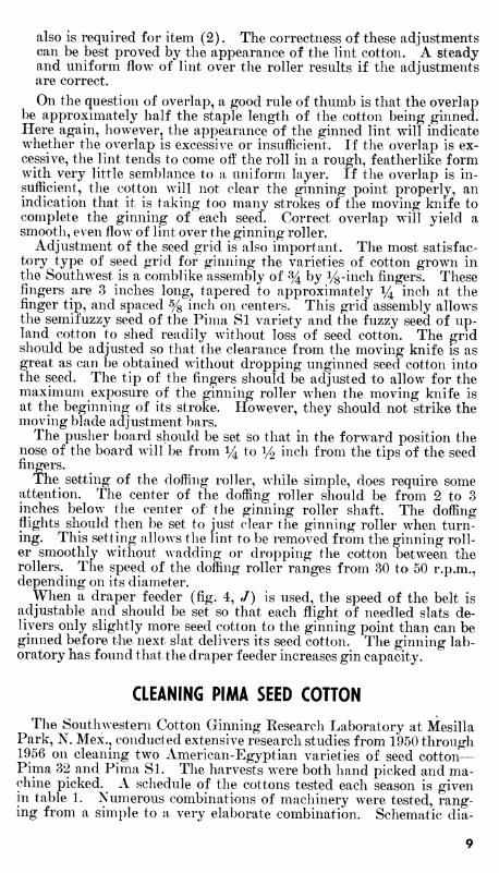
The Southwestern Cotton Ginning Research Laboratory at Mesilla Park, N. Mex., conducted extensive research studies from 1950 through 1956 on cleaning two American-Egyptian varieties of seed cotton— Pima 32 and Pima Si. The harvests were both hand picked and ma- chine picked. A schedule of the cottons tested each season is given in table 1. Numerous combinations of machinery were tested, rang- ing from a simple to a very elaborate combination. Schematic dia-
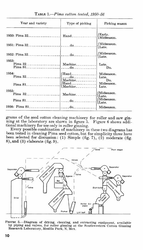
TABLE 1.—Pima cotton tested^ 1950-56
Year and variety Type of picking Picking season
1950: Pima 32 Hand íEarly. IMidseason.
ÍMidseason. ILate.
ÍMidseason. ILate.
Late.
1951: Pima 32 do
1952: Pima 32 do
1953: Pima 32 Machine Pima SI do Do
1954: ÍHand.__ Midseason. Pima 32 do
Machine Late.
Do. Pima SI /Hand Midseason.
IMachine Late. 1955:
Pima 32 Machine ÍMidseason. [Late. /Midseason. ILate. Midseason
Pima SI do
1956: Pima SI do
grams of the seed cotton cleaning machinery for roller and saw gin- ning at the laboratory are shown in figure 5. Figure 6 shows addi- tional machinery for use only in roller ginning.
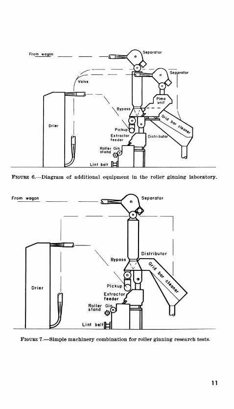
Every possible combination of machinery in these two diagrams has been tested in cleaning Pima seed cotton, but for simplicity three have been selected for discussion: (1) Simple (fig. 7), (2) moderate (fi^. 8),and (3) elaborate (fig. 9).
Separator
FIGURE 5.—Diagram of drying, cleaning, and extracting equipment, available by piping and valves, for roller ginning at the Southwestern Cotton Ginning Research Laboratory, Mesilla Park, N. Mex.
10
From V« agon sr^^/ ^Separator
s:^
y^^ ■^^3.—__/ \ Separator
/Valve ^"^
^
X f Pima \ —1 unit yl
Drier
p
1
\ Bypass i
\
Pickup *"
Extractor ^ feeder /
^ Distributors.
1 r
^ Al Roller Gin 1 t
J 1 ^♦^"^l ^
Lint belt [tj|
FIGURE 6.—Diagram of additional equipment in the roller ginning laboratory.
From wagon
Drier
Separator
Distributor
Roller Gi stand ^^1
Lint beit^j
FiGUEE 7.—Simple machinery combination for roller ginning research tests.
n
From wogon
SeporatorV^-,^"^ w
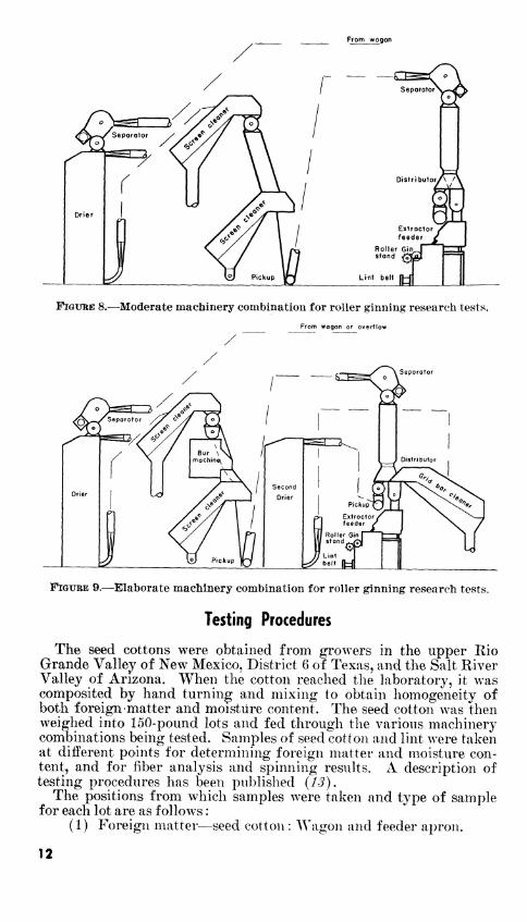
FIGURE 8.—Moderate machinery combination for roller ginning research tests. From wagon or overflow
FIGURE 9.—Elaborate machinery combination for roller ginning research tests.
Testing Procedures
The seed cottons were obtained from growers in the upper Rio Grande Valley of New Mexico, District 6 of Texas, and the Salt River Valley of Arizona. When the cotton reached the laboratory, it was composited by hand turning and mixing to obtain homogeneity of both foreign matter and moisture content. The seed cotton was then weighed into 150-pound lots and fed through the various machinery combinations being tested. Samples of seed cotton and lint were taken at different points for determining foreign matter and moisture con- tent, and for fiber analysis and spinning results. A description of testing procedures has been published (J-^)-
The positions from which samples were taken and type of sample for each lot are as follows :
(1) Foreign matter—seed cotton : AVagon and feeder apron.
12
(2) Moisture—seed cotton: Wagon and feeder apron. (3) Moisture—lint : Before and after lint cleaning. (4) Fiber classification—grade and staple: Before and after
lint cleaning. (5) Fiber analyses—strength, upper half mean length, fineness,
maturity, uniformity, fiber nep count, fiber array : Before and after lint cleaning.
(6) Shirley analyzer or nonlint content: Percentage of foreign matter remaining in the ginned lint.
(7) Spinning results: Lint samples, before and after lint clean- ing, were card web nep count, picker and card waste, yam strength, yam appearance.
Hand-picked Undefoliated Cotton
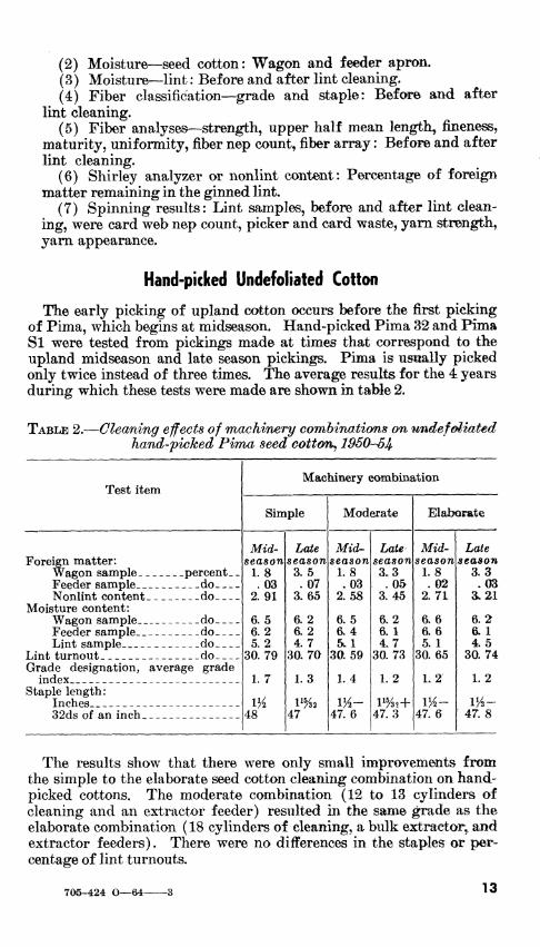
The early picking of upland cotton occurs before the first picking of Pima, which begins at midseason. Hand-picked Pima 82 and Pima SI were tested from pickings made at times that correspond to the upland midseason and late season pickings. Pima is usually picked only twice instead of three times. The average results for the 4 years during which these tests were made are shown in table 2.
TABLE 2.—Cleaning effects of machinery combinations on undefoliated hand-picked Pima seed cotton^ 19S0S4.
Test item Machinery combination
Simple Moderate Elaborate
Foreign matter: Wagon sample percent. _ Feeder sample do Nonlint content do
Moisture content: Wagon sample do Feeder sample do Lint sample do
Lint turnout do Grade designation, average grade
index Staple length:
Inches 32ds of an inch
Mid- season l.S .03
2.91
6.5 6.2 5.2
30.79
1. 7
IK 48
Late season 3.5 .07
3.65
6.2 6.2 4.7
30.70
L3
47
Mid-- season
1.8 .03
2. 58
6.5 6.4 5tl
30.59
1.4
IK- 47. 6
Late season 3,3 .05
3.45
6.2 6.1 4.7
30. 73
1.2
47.3
Mid- season
1.8 .02
2. 71
ao 6.6 5. 1
30. 65
L2
iy2- 47. 6
Late season
3.3 .03
3.21
6.2 a 1 4.5
30.74
1. 2
m- 47. 8
The results show that there were only small improvements from the simple to the elaborate seed cotton cleaning combination on hand- picked cottons. The moderate combination (12 to 13 cylinders of cleaning and an extractor feeder) resulted in the same grade as the elaborate combination ( 18 cylinders of cleaning, a bulk extractor, and extractor feeders). There were no differences in the staples or per- centage of lint turnouts.
705-424 O—64- 13
Machine-picked Undefoliated Cotton
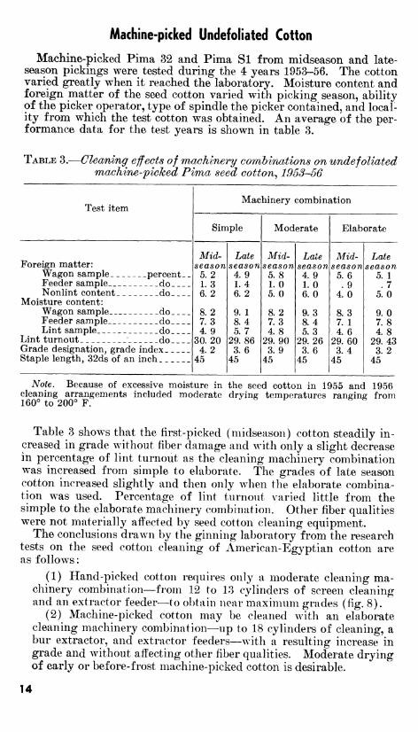
Machine-picked Pima 32 and Pima Si from midseason and late- season pickings were tested during the 4 years 1953-56. The cotton varied greatly when it reached the laboratory. Moisture content and foreign matter of the seed cotton varied with picking season, ability of the picker operator, type of spindle the picker contained, and local- ity from which the test cotton was obtained. An average of the per- formance data for the test years is shown in table 3.
TABLE 3.—Gleaning effects of machinery combinations on undefoliated machine-picked Pima seed cotton^ 1953-56
Test item
Foreign matter: Wagon sample percent- _ Feeder sample do Nonlint content do
Moisture content: Wagon sample do Feeder sample do Lint sample do
Lint turnout " do Grade designation, grade index Staple length, 32ds of an inch
Machinery combination
Simple
season 5.2 L3 6.2
8.2 7.3 4. 9
30. 20 4. 2
45
Late season
4. 9 1. 4 6. 2
9. 1 8. 4 5. 7
29. m 3. 6
45
Moderate Elaborate
Mid- season
5. 8 LO 5.0
8.2 7.3 4. 8
29. 90 3.9
45
Late season
4. 9 LO 6.0
9.3 8.4 5.3
29.26 3.6
45
Mid- season 5.6 .9
4.0
8.3 7. 1 4. 6
29.60 3.4
45
Late season
5. 1 . 7
5.0
9.0 7.8 4.8
29.43 3.2
45
Note. Because of excessive moisture in the seed cotton in 1955 and 1956 cleaning arrangements included moderate drying temperatures ranerinff from 160° to 200° F. ^ ^ ^ B ^
Table 3 shows that the first-picked (midseason) cotton steadily in- creased in grade without fiber damage and with only a slight decrease in percentage of lint turnout as the cleaning machinery combination was increased from simple to elaborate. The grades of late season cotton increased slightly and then only when the elaborate combina- tion was used. Percentage of lint turnout varied little from the simple to the elaborate machinery combination. Other fiber qualities were not materially affected by seed cotton cleaning equipment.
The conclusions drawn by the ginning laboratory from the research tests on the seed cotton cleaning of American-Egyptian cotton are as follows:
(1) Hand-picked cotton requires only a moderate cleaning ma- chinery combination—from 12 to 13 cylinders of screen cleaning and an extractor feeder—to obtain near maximum grades (fig. 8).
(2) Machine-picked cotton may be cleaned with an elaborate cleaning machinery combination—up to 18 cylinders of cleaning, a bur extractor, and extractor feeders—with a resulting increase in grade and without affecting other fiber qualities. Moderate drying of early or before-frost machine-picked cotton is desirable.
14
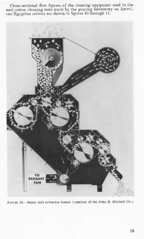
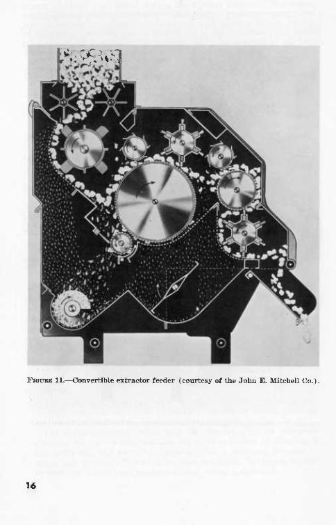
Cross-sectional flow figures of the cleaning equipment used in the seed cotton cleaning tests made by the ginning laboratory on Ameri- can-Egyptian cottons are shown in figures 10 through 14.
^,> 0«<3ù
FIGURE 10.—Super unit extractor feeder (courtesy of the John E. Mitchell Co.).
15
'^.:>;^%>1
FiGUBE H.—Convertible extractor feeder (courtesy of the John E. Mitchell Co.).
1«
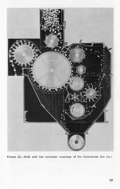
FiouBE 12.—Bulk unit bur extractor (courtesy of the Continental Gin Co.).
17
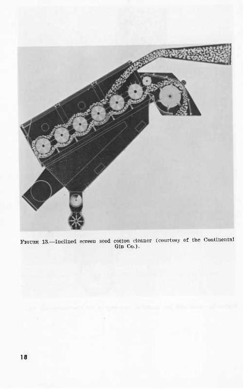
FIGURE 13.—Inclined screen seed cotton cleaner (courtesy of the Continental Gin Co.)-
18
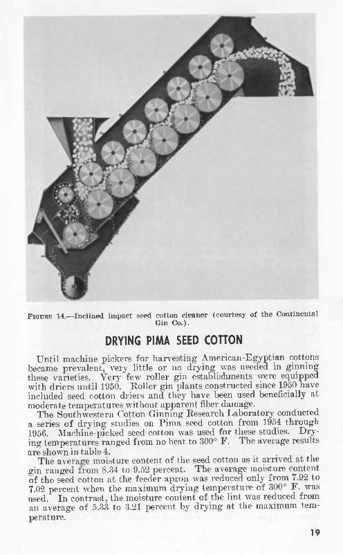
FIGURE 14.—Inclined impact seed cotton cleaner (courtesy of the Continental Gin Co.).
DRYING PIMA SEED COHON Until machine pickers for harvesting American-Egyptian cottons
became prevalent, very little or no drying was needed in ginning these varieties. Very few roller gin establishments were equipped with driers until 1950. Roller gin plants constructed since 1950 have included seed cotton driers and they have been used beneficially at moderate temperatures without apparent fiber damage.
The Southwestern Cotton Ginning Research Laboratory conducted a series of drying studies on Pima seed cotton from 1954 through 1956. Machine-picked seed cotton was used for these studies. Dry- ing temperatures ranged from no heat to 300° F. The average results are shown in table 4.
The average moisture content of the seed cotton as it arrived at the gin ranged from 8.34 to 9.52 percent. The average moisture content of the seed cotton at the feeder apron was reduced only from 7.92 to 7.02 percent when the maximum drying temperature of 300° F. was used. In contrast, the moisture content of the lint was reduced from an average of 5.33 to 3.21 percent by drying at the maximum tem- perature.
19
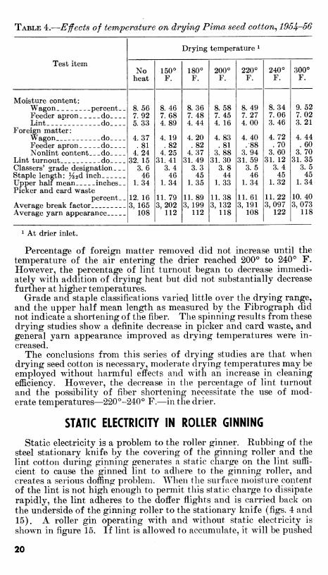
TABLE 4.—Effects of temperature on drying Pima seed cotton^ 195^-56
Test item
Drying temperature *
No heat
150° F.
180° F.
200° F.
220° F.
240° F.
300° F.
Moisture content: Wagon percent- Feeder apron do Lint do
Foreign matter: Wagon do Feeder apron do Nonlint content do
Lint turnout do Classers' grade designation. _ Staple length: ^2d inch Upper half mean inches. Picker and card waste
percent. Average break factor Average yarn appearance
8.56 7.92 5.33
4.37 .81
4.24 32. 15
3.6 46
1.34
12. 16 3, 165
108
8. 46 7.68 4.89
4. 19 .82
4.25 31. 41
3.4 46
1.34
11. 79 3,202
112
8.36 7.48 4. 44
4.20 .82
4.37 31.49
3.3 45
1.35
11.89 3, 199
112
8. 58 7.45 4. 16
4.83 .81
3.88 31.30
3.8 44
1.33
11.38 3, 132
118
8. 49 7. 27 4.00
4. 40 .88
3. 94 31. 59
3.5 46
1.34
11.61 3, 191
108
8.34 7.06 3.46
4.72 .70
3.60 31. 12
3.4 45
1. 32
11.22 3,097
122
9.52 7.02 3. 21
4. 44 . 60
3.70 31.35
3.5 45
1.34
10. 40 3,073
118
1 At drier inlet.
Percentage of foreign matter removed did not increase until the temperature of the air entering the drier reached 200° to 240° F. However, the percentage of lint turnout began to decrease immedi- ately with addition of drying heat but did not substantially decrease further at higher temperatures.
Grade and staple classifications varied little over the drying range, and the upper half mean length as measured by the Fibrograph did not indicate a shortening of the fiber. The spinning results from these drying studies show^ a definite decrease in picker and card waste, and general yarn appearance improved as drying temperatures were in- creased.
The conclusions from this series of drying studies are that when drying seed cotton is necessary, moderate drying temperatures may be employed without harmful effects and with an increase in cleaning efficiency. However, the decrease in the percentage of lint turnout and the possibility of fiber shortening necessitate the use of mod- erate temperatures—220°-240° F.—in the drier.
STATIC ELECTRICITY IN ROLLER GINNING
Static electricity is a problem to the roller ginner. Rubbing of the steel stationary knife by the covering of the ginning roller and the lint cotton during ginning generates a static charge on the lint suffi- cient to cause the ginned lint to adhere to the ginning roller, and creates a serious doffing problem. When the surface moisture content of the lint is not high enough to permit this static charge to dissipate rapidly, the lint adheres to the doffer flights and is carried back on the underside of the ginning roller to the stationary knife (figs. 4 and 15). A roller gin operating with and without static electricity is shown in figure 15. If lint is allowed to accumulate, it will be pushed
20
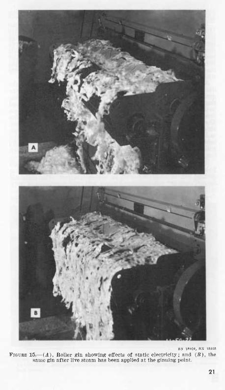
BN 18404, BN 18403
FIGURE 15.— (A), Roller gin showing efifects of static electricity; and (B), the same gin after live steam has been applied at the ginning point.
21
into the path of the moving knife. This generally damages the knives and the ginning roller covering.
In a series of experiments, workers at the Southwestern Cotton Ginning Eesearch Laboratory have attempted to eliminate undesirable static electricity at the roller gin. Spinning-mill types of misting spray nozzles were tried at numerous positions about the gin. The resulting accumulation of moisture on the machinery prevented their practical use. High potential ionization bars were investigated and reduced static electricity, but the air could not be ionized at a location that would allow the roller and doffer to shed the cotton satisfactorily without prohibitive costs.
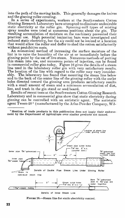
An economical method of increasing the surface moisture of the lint is to raise the humidity of the air at or immediately before the ginning point by the use of live steam. Numerous methods of putting this steam into use, and numerous points of injection, can be found in commercial roller gins today. Figure 16 gives the details of a steam line used in the laboratory roller gin with very satisfactory results. The location of the line with regard to the roller may vary consider- ably. The laboratory has found that mounting the steam line below and to the back of the center line of the ginning roller with the outlet holes directed toward the ginning area produces satisfactory results with a small amount of steam and a minimum accumulation of dirt, lint, and trash in the gin stand or seed board.
Eesults of recent tests at the Southwestern Cotton Ginning Eesearch Laboratory and in commercial gins show that static electricity during ginning can be controlled with an antistatic agent. The antistatic agent Tween-20 ^ (manufactured by the Atlas Powder Company, Wil-
' Mention of trade products in this pubUcation does not imply their endorse- ment by the Department of Agriculture over similar products not named.
Outer pipe 'A" galvanized
Inner pipe Ve" copper tubim
Location of steam line under ginning roller
Steam pipe outlet holes
'/|6" dia. 2" o.e. (counter sink )
'/*" galvanized steam line from
-steam supply
~^^^É^ Details of Double Pipe Steam Line Under Ginning Roller
^
Bore A" galvanized
Steam outlet holes P*P^ *° Vs" pipe and '/l6"dia. 2" o.e. . ^^oáBT together
-^ rr''''^-*i V / ^3/8" copper tubing »
Details of Inner Steam Line
FiGUEE 16.—Steam line for static electricity control.
22
mington, Del.) was tested for controlling static in a roller gin by two methods: (1) spray application to seed cotton; (2) direct application to the gin roller. The first was unsatisfactory; the second was satis- factory both in laboratory tests and at commercial gins. A mixture of 1 to 2 parts of water and 1 part of Tween-20 was applied to the gin rolls manually with a brush. Frequency of application was de- termined by the static conditions. Some ginners reported using two applications per day of approximately 1 gallon of Tween-20 per 100 bales of cotton (6).
PNEUMATIC CONVEYING AND CLEANING OF PIMA LINT
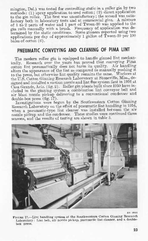
The modern roller gin is equipped to handle ginned lint mechan- ically. Eesearch over the years has proved that conveying Pima cotton lint pneumatically does not harm its quality. Air handling alters the appearance of the lint as compared to manually pushing it to the press, but otherwise lint quality remains the same. "Workers at the U.S. Cotton Ginning Research Laboratory at Stoneville, Miss., de- signed and installed a suction nozzle and lint flue system first m 1936 at Casa Grande, Ariz. (fig. 2). Koller gin plants built since 1950 have in- cluded in the ginning system a combination lint conveyor belt and air blast nozzle pickup delivering to a conventional condenser and double-box press (fig. 17). ^i- ■
Investigations were begun by the Southwestern Cotton Gmnmg Eesearch Laboratory on the effect of pneumatic lint handling in 1954, when a pneumatic-type lint cleaner was installed between the air nozzle pickup and the condenser. These studies were continued three seasons, and the results of testing are shown in table 5.
BN 18401
FIGURE 17.—Lint handling system at the Southwestern Cotton Ginning Research Laboratory : Lint belt, air nozzle pickup, pneumatic lint cleaner, and a double- box press.
23
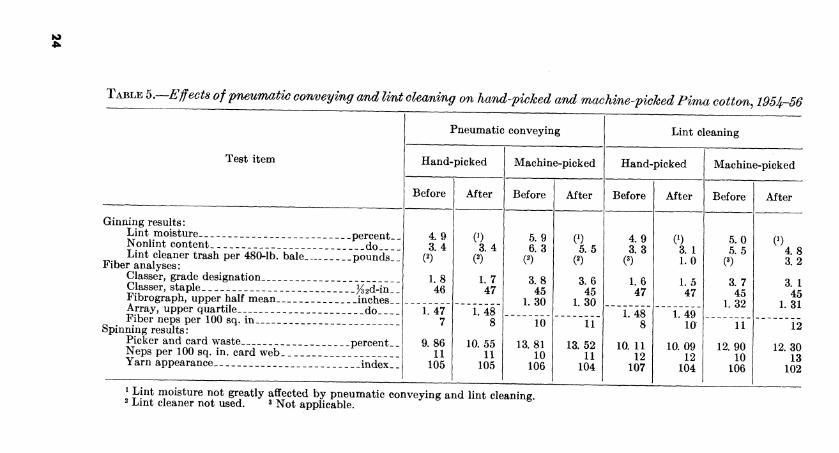
TABLE b.—Ejfects of pneumatic conveying and lint cleaning on harui-picked and machine-picked Pima cotton, 1954-56
Test item
Ginning results: Lint moisture percent.. Nonlint content do Lint cleaner trash per 480-Íb. bale Tpounds]^
Fiber analyses: Classer, grade designation Classer, staple K2d-in_ I Fibrograph, upper half mean inchest ' Array, upper quartile do Fiber neps per 100 sq. in
Spinning results : Picker and card waste percent. _ Neps per 100 sq. in. card web Yarn appearance index' I
Pneumatic conveying
Hand-picked
Before
4.9 3.4
1.8 46
1.47 7
9.86 11
105
After
0) 3.4
1.7 47
1.48 8
10.55 11
105
Machine-picked
Before
5. 9 6.3
3.8 45
L30
10
13.81 10
106
1 Lint moisture not greatly affected by pneumatic conveying and lint cleaning 2 Lmt cleaner not used. 3 JNJQ^ applicable.
After
0) 5.5
3.6 45
1.30
11
13. 52 11
104
Lint cleaning
Hand-picked
Before
4.9 3.3
1.6 47
L48
10. 11 12
107
After
0) 3. 1 1.0
1.5 47
1.49 10
10.09 12
104
Machine-picked
Before
5.0 5.5
3.7 45
1. 32
11
12.90 10
106
After
0) 4.8 3.2
3. 1 45
L31
12
12.30 13
102
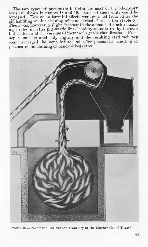
The two types of pneumatic lint cleaners used in the laboratory tests are shown in figures 18 and 19. Each of these units could be bypassed. Few or no harmful effects were detected from either the air handling or lint cleaning of hand-picked Pima cotton (table 5). There was, however, a slight decrease in the amount of trash remain- ing in the lint after pneumatic lint cleaning, as indicated by the non- lint content and the very small increase in grade classification. Fiber nep count increased only slightly and the resulting card web nep count averaged the same before and after pneumatic handling or pneumatic lint cleaning on hand-picked cotton.
FIGURE 18.—Pneumatic lint cleaner (courtesy of the Murray Co. of Texas).
25
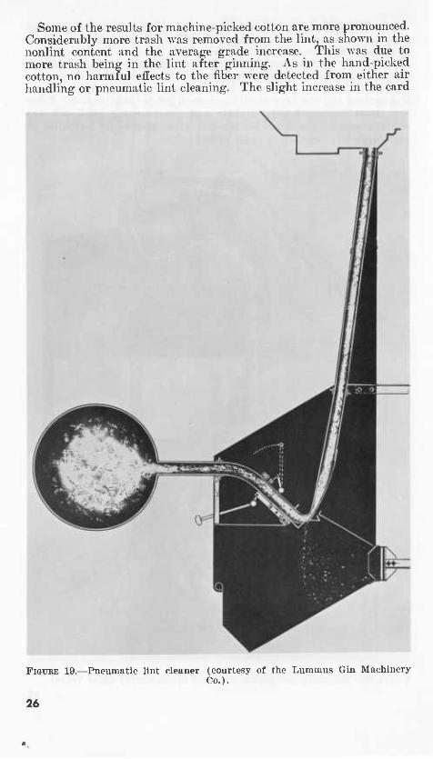
Some of the results for machine-picked cotton are more pronounced. Considerably more trash was removed from the lint, as shown in the nonlint content and the averaj^e grade increase. This was due to more trash being in the lint after ginning. As in the hand-picked cotton, no harmful effects to the fiber were detected from either air handling or pneumatic lint cleaning. The slight increase in the card
FIGURE 19.—Pneumatic lint cleaner (courtesy of the Lummus Gin Machinery Co.).
26
web nep count probably accounts for the small decrease in average yarn appearance.
The conclusion of the ginning laboratory after 3 years of study is that air handling and pneumatic lint cleaning of hand-picked and of machine-picked cotton can be done without detectable fiber damage.
SAW GINNING PIMA COHON
Considerable interest has been voiced in the results of saw ginning American-Egyptian or Pima cotton. There is no evidence that this practice exists anywhere commercially, and only limited data are available from research on saw ginning Pima.
Small-scale studies of the saw ginning of American-Egyptian cotton have been undertaken at the Southwestern Cotton Ginning Research Laboratory several times in the past few years, primarily to establish a guide as to the results to be expected from this method of ginning Pima cotton. Prior to the development of thé' Pima Si variety that has a semifuzzy seed, ginning Pima on a conventional saw gin was practically impossible because a seed roll could not be maintained. The Pima Si variety can be ginned on a saw gin under certain me- chanical conditions. In 1956, limited tests were made under different gin settings, such as saw spacing, air doffing pressures, methods of doffing, and a few different saw tooth designs.
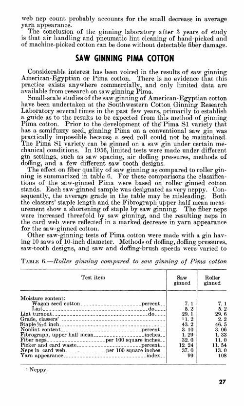
The effect on fiber quality of saw ginning as compared to roller gin- ning is summarized in table 6. For these comparisons the classifica- tions of the saw-ginned Pima were based on roller ginned cotton stands. Each saw-ginned sample was designated as verv neppy. Con- sequently, the average grade in the table may be misleading. Both the classers' staple length and the Fibrograph upper half mean meas- urement show a shortening of staple by saw ginning. The fiber neps were increased threefold by saw ginning, and the resulting neps m the card web were reflected in a marked decrease in yarn appearance for the saw-ginned cotton.
Other saw-ginning tests of Pima cotton were made with a gin hav- ing 10 saws of 10-inch diameter. Methods of doffing, doffing pressures, saw-tooth designs, and saw and doffing-brush speeds were varied to
TABLE 6.—Roller ginning compared to saw ginning of Pima cotton
Test item Saw Roller ginned ginned
7. 1 7. 1 5.2 5.2
29. 1 29. 6 11.2 2.2 43.2 46.5 3. 10 3.06 1.29 1.33 32.0 11.0
12. 24 11.54 37.0 13.0
99 108
Moisture content: Wagon seed cotton percent Lint do__
Lint turnout do_ _ Grade, classers' Staple H2d inch Nonlint content percent Fibrograph, upper half mean inches Fiber neps per 100 square inches. Picker and card waste percent. Neps in card web per 100 square inches Yarn appearance index
1 Neppy.
27
obtain basic information as to where the fiber damage was taking place in the gin stand. The results of these pilot ginning tests con- firmed previous tests as to the high nep formation and fiber shorten- ing. They also indicated that these harmful effects on the fiber were accumulative in the seed roll and were not the effect of any one opera- tion within the stand such as speed or doffing method.
SUMMARY
Roller ginning in the Southwest was begun early in the 20th cen- tury in the Imperial Valley of California and the Salt River Valley of Arizona. In 1920 more than 92,000 bales of Pima cotton were pro- duced in this country. Since 1920 production of American-Egyptian cotton has varied greatly, and concurrently changes and improvements in roller gin machinery design have been spasmodic. An increase in production during World War II supplied the incentive for manu- facturing new models of roller gins in 1942, but it was not until 1950 that American-Egyptian cotton production sparked further improve- ments in roller gin design. From 1942 to 1950 the general conception of gin-plant designs and gin-machinery requirements changed from two-story buildings and comparatively simple seed cotton cleaning machinery plus very gentle handling of the cotton to the present-day single-story gin building equipped with modern upland-cotton-type cleaning machinery operating on a mass-production basis.
Roller ginning research was begun by the Department of Agricul- ture as far back as 1925. However, it was not until 1936 that exten- sive research on cleaning, drying, and lint handling was undertaken. Research on the adjustments and operations of today's roller gins has yielded basic engineering guides for operators in the field. Seed cot- ton cleaning and drying procedures ranging from simple to elaborate systems have shown that American-Egyptian varieties now grown can. be cleaned and dried by modern machinery and approved techniques without harming the quality of the fiber. Research has also shown that pneumatic conveying of both the seed cotton and the lint do not harm fiber quality. Pneumatic lint cleaners are being used to improve the grades without significant damage.
Improved methods of applying steam at the gin stand are controlling static on the ginning roller. Copies of the design of a satisfactory two-pipe steam system are available at the ginning laboratories.
Additional studies at both the ginning laboratory and at commercial gins show that antistatic chemicals can be used to control static elec- tricity. Brush applications of a solution of TAveen-20 and water to the seed roll have proved satisfactory.
28
LITERATURE CITED
(1) ARKANSAS-MISSOURI COTTON GINNERS ASSOC.
[n.d.] COTTON GINNER'S HANDBOOK. 159 pp., illus. Blytheville, Ark. (2) BENNETT, C. A.
1943. SIMPLIFIED PITOT TUBE CALCULATIONS OF AIB FLOW IN DUCTS AND PIPES. Rev. Bur. Plant Indus., Soils and Agr. Engin., U.S. Dept. Agr., 16 pp. [Processed.]
(3) [1959] ROLLER COTTON GINNING DEVELOPMENTS. TexaS CottOU GiUUers'
Assoc & The Cotton Gin and Oil Mill Press, joint sponsors, 90 pp., illus.
(4) BUFFALO FORGE COMPANY.
1949. FAN ENGINEERING. Ed. 5, 808 pp., iUus. Buffalo, N.Y. (5) JOHNSON, A. J., TOWNSEND, J. S., and WALTON, T. C.
1941. AMERICAN-EGYPTIAN COTTON QUALITY AND GINNING. Agr. Market. Sew., Bur. Plant Indus., and Bur. Agr. Chem. and Engin. U.S. Dept. Agr., 16 pp., illus. [Processed.]
(6) LEONARD, C. G.
1960. CONTROLLING STATIC ELECTRICITY ON COTTON DURING GINNING WITH
AN ANTISTATIC AGENT. U.S. Dept. Agr., Agr. Res. Serv., ARS 42-39, 16 pp., illus.
(7) SHAW, E. A. & Co., INC.
[n.d.] AMERICAN-EGYPTIAN COTTONS. A BRIEF HISTORY OF THIER DEVELOP- MENT AND DESCRIPTION OF THEIR CHARACTERISTICS, 1900-1950. 18 pp. Boston.
(8) STEDRONSKY, V. L.
1956. EXTRA LONG STAPLE COTTON AND ROLLER GINNING. The CottOU Ginners' Jour. Yearbook, v. 24, No. 1, pp. 37-39, illus.
(9) TEXAS COTTON GINNERS' ASSOC.
[n.d.] WHAT WE KNOW ABOUT AIR POLLUTION CONTROL. Spec. Bui. 1, 31 pp., illus. Dallas.
(10) TOWNSEND, J. S. 1925. GINNING PIMA CJOTTON IN ARIZONA. U.S. Dept. Agr. Dept. Bui.
1319,10 pp., illus. (11) ^ MARTIN, W. J. and WALTON, T. C.
1940. SEA-ISLAND COTTON QUALITY AND GINNING. U.S. Dept. Agr., ACE-69,15 pp., illus.
(12) , WALTON, T. C, and MARTIN, W. J. 1940. ROLLER GIN CONSTRUCTION, MAINTENANCE, AND OPERATION. U.S.
Dept Agr., ACE-68, 14 pp., illus. (13) UNITED STATES DEPARTMENT OF AGRICULTURE
1955. COTTON TESTING SERVICE : TESTS AVAILABLE, EQUIPMENT AND TECH-
NIQUES, AND BASIS FOR INTERPRETING RESULTS. U.S. Agr. Market. Serv., AMS 16, 49 pp., illus.
(14) 1956. MODERNIZING COTTON GINS. Agr. Haudb. 99, 45 pp., illus.
(15) 1963. AGRICULTURAL STATISTICS. 1962: 83.
(16) WARE, J. O. 1936. PLANT BREEDING AND THE COTTON INDUSTRY. U.S. Dept Agr.
Yearbook 1936: 657-744.
29
APPENDIX
Supplemental engineering data applicable to roller ginning are provided in this appendix. In addition, the reader is referred to other literature (i, P, i^).
Fans and Piping
For handling materials efficiently by air, it is important to consider (a) the rate of flow or velocity, and (b) the volume of air per pound of material.
Materials commonly handled at the cotton gin by air and the veloc- ities normally required for efficient handling are as follows :
Velocity for materials in pipes (Feet per minute)
Seed cotton 4, 000-4, 500 Seed cotton in tower driers 1, 200 Dried seed cotton (from machine to machine) 3, 000 BoUies in tower drier 1, 500-1, 600 Seed 5, 000-5, 500 Hulls and trash 3,000-4,000 Lint cotton 1, 000-1, 500
Volume of air normally required per pound of material to be handled is as follows :
Volume of air per pound of material (Cubic feet per minute)
Low pressure fans (8 to 20 inches of water) 40-50 Seed pumps 5-6
In handling material by air, two things must be satisfied: (1) Eate of flow, and (2) volume of flow.
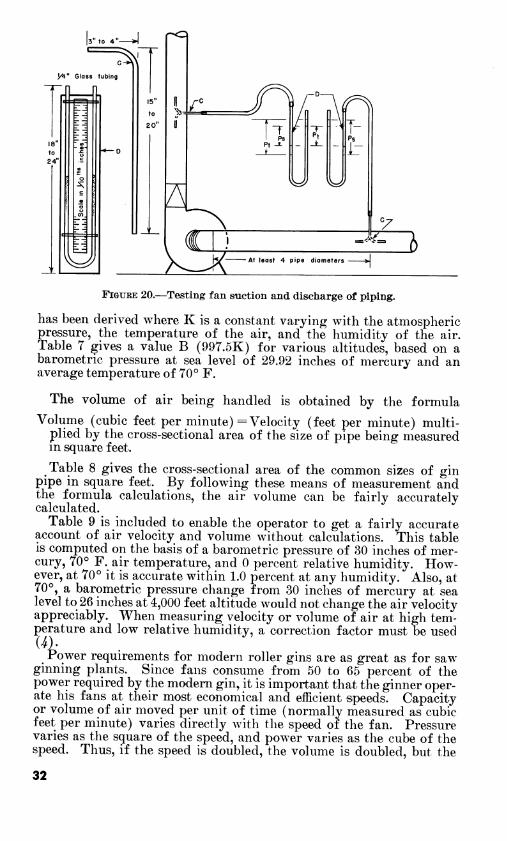
The gin operator can measure and calculate the air velocity and the air volume of a system by a simple method (^, ^). All that he needs to make these measurements is a Pitot tube (C) and a U-tube or manometer (D), shown in figure 20. The procedure is as follows :
First make a small hole in the pipe in which the air is to be meas- ured, at least 4 diameters away from the fan or any elbow or other interference in the straight flow of air. Insert the Pitot tube into the hole and point the nose or open end upstream with the tube parallel with the pipe and in the center of the pipe. The difference shown between the two water columns in the manometer is the impact or total pressure (Pt). By removing the Pitot tube and placing one lead from the manometer against the hole or by pointing the Pitot tube downstream to the direction of air flow the difference in the man- ometer water columns is the resistance or static pressure (Ps) of the piping. The difference between the total pressure (Pt) and the static pressure (Ps) is the velocity pressure (Pv). From basic engineer- ing formulae the equation
V (velocity in feet per minute) =997.5K \/Fv (velocity pressure in inches of water)
31
3" to 4"-
7^ y4" Glass tubing
15"
to
20"
a ^^=^
T- Ps
*^
°z
KZ>^ i
At least 4 pipe diameters
FIGURE 20.—Testing fan suction and discharge of piping.
has been derived where K is a constant varying with the atmospheric pressure, the temperature of the air, and the humidity of the air. Table 7 gives a value B (997.5K) for various altitudes, based on a barometric pressure at sea level of 29.92 inches of mercury and an average temperature of 70° F.
The volume of air being handled is obtained by the formula
Volume (cubic feet per minute) = Velocity (feet per minute) multi- plied by the cross-sectional area of the size of pipe being measured in square feet.
Table 8 gives the cross-sectional area of the common sizes of gin pipe in square feet. By following these means of measurement and the formula calculations, the air volume can be fairly accurately calculated.
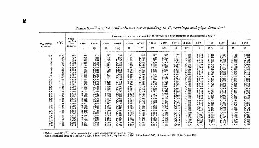
Table 9 is included to enable the operator to get a fairly accurate account of air velocity and volume without calculations. This table is computed on the basis of a barometric pressure of 30 inches of mer- cury, 70° F. air temperature, and 0 percent relative humidity. How- ever, at 70° it is accurate within 1.0 percent at any humidity. Also, at 70°, a barometric pressure change from 30 inches of mercury at sea level to 26 inches at 4,000 feet altitude would not change the air velocity appreciably. When measuring velocity or volume of air at high tem- perature and low relative humidity, a correction factor must be used
Power requirements for modern roller gins are as great as for saw ginning plants. Since fans consume from 50 to 65 percent of the power required by the modem gin, it is important that the ginner oper- ate his fans at their most economical and efficient speeds. Capacity or volume of air moved per unit of time (normally measured as cubic feet per minute) varies directly with the speed of the fan. Pressure varies as the square of the speed, and power varies as the cube of the speed. Thus, if the speed is doubled, the volume is doubled, but the
32
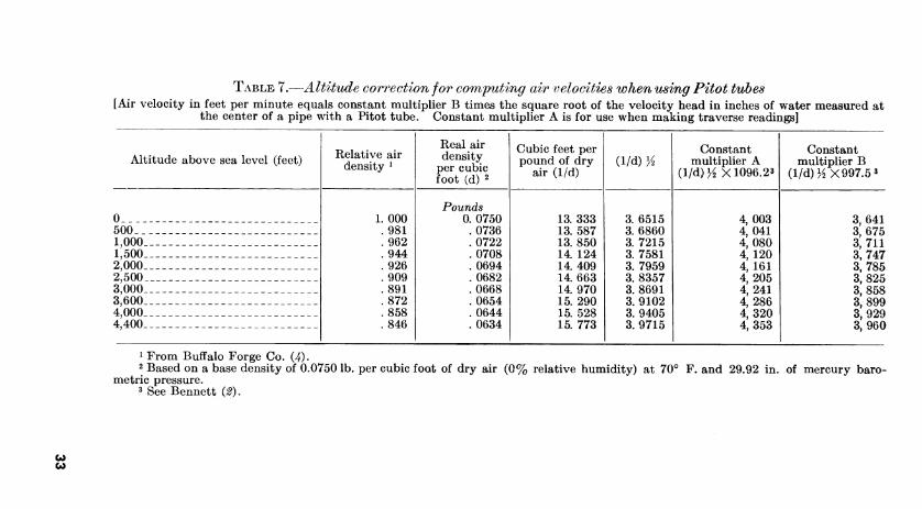
TABLE 7.—Altitude connection for commuting air velocities when using Pitot tubes [Air velocity in feet per minute equals constant multiplier B times the square root of the velocity head in inches of water measured at
the center of a pipe with a Pitot tube. Constant multiplier A is for use when making traverse readings]
Altitude above sea level (feet) Relative air density ^
Real air density
per cubic foot (d) 2
Cubic feet per pound of dry
air (1/d) (1/d) /2
Constant multiplier A
(1/d) H X 1096.23
Constant multiplier B
(1/d) 1/2X997.5 3
0 500 _. 1,000 1,500 2,000 2,500 3,000 3,600 4,000 4,400
000 981 962 944 926 909 891 872 858 846
Pounds 0. 0750 .0736 . 0722 .0708 . 0694 .0682 .0668 .0654 . 0644 . 0634
13. 333 13. 587 13. 850 14. 124 14. 409 14. 663 14. 970 15. 290 15. 528 15. 773
3. 6515 3. 6860 3. 7215 3. 7581 3. 7959 3. 8357 3. 8691 3. 9102 3. 9405 3. 9715
4,003 4,041 4,080 4, 120 4, 161 4,205 4,241 4,286 4,320 4,353
3,641 3,675 3,711 3,747 3,785 3,825 3,858 3,899 3,929 3,960
1 From Buffalo Forge Co. (4). 2 Based on a base density of 0.0750 lb. per cubic foot of dry air (0% relative humidity) at 70° F. and 29.92 in. of mercury baro-
metric pressure. 3 See Bennett i2).
CO
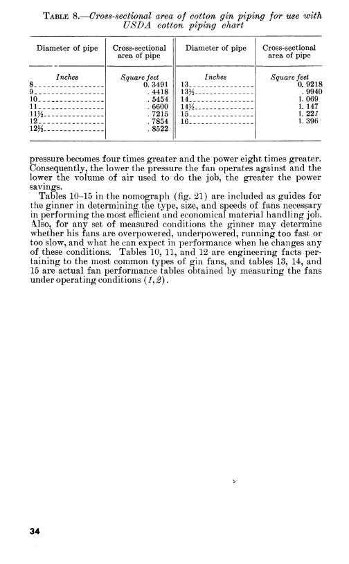
TABLE 8.—O ross-sectional area of cotton gin piping for use with ÜSDA cotton piping chart
Diameter of pipe Cross-sectional area of pipe
Diameter of pipe Cross-sectional area of pipe
Inches 8 -_.___-_
S,qu<ire feet 0. 3491 .4418 .5454 .6600 .7215 .7854 .8522
Inches 13
Square feet 0. 9218
9 _- - 13H - .9940 10 14_ _ _ _ __ _ 1.069 11 __ _ _ 14H
15 - - -_- -_ 1. 147
11^2 1.227 12 16 1.396 12H
pressure becomes four times greater and the power eight times greater. Consequently, the lower the pressure the fan operates against and the lower the volume of air used to do the job, the greater the power savings.
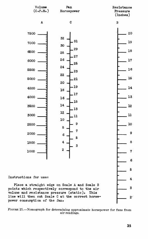
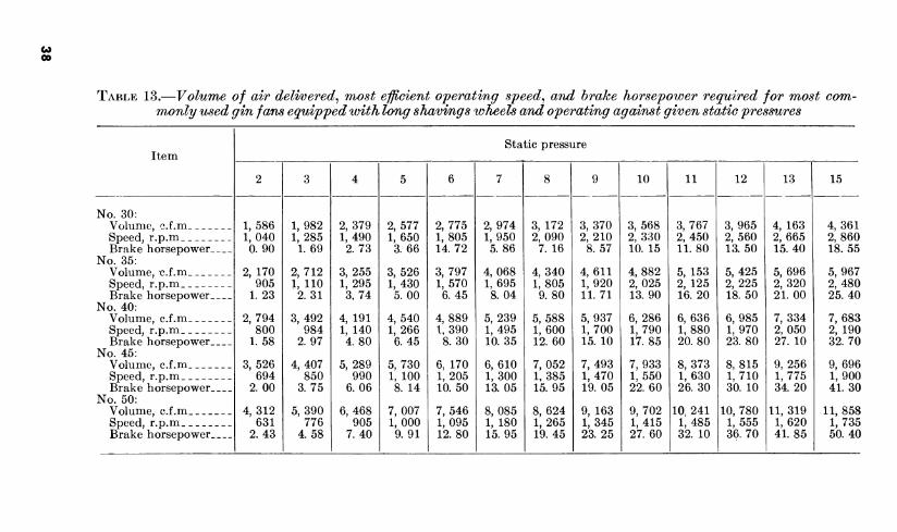
Tables 10-15 in the nomograph (fig. 21) are included as guides for the ginner in determining the type, size, and speeds of fans necessary in performing the most efficient and economical material handling job. A^lso, for any set of measured conditions the ginner may determine whether his fans are overpowered, underpowered, running too fast or too slow, and what he can expect in performance when he changes any of these conditions. Tables 10, 11, and 12 are engineering facts per- taining to the most common types of gin fans, and tables 13, 14, and 15 are actual fan performance tables obtained by measuring the fans under operating conditions (i, ^).
34
Volume (C.F.M.)
Fern Horsepower
7500
7000
6600
6000
5500
6000
4500
4000
3500
3000
2500.
2000
1500
1000
32
30
28
26
24
22
20 -I
18
16
14
12
10
8
6
4
2 «
-.31
29
-27
-.25
23
«21
-19
-17
15
-.13
-11
- 9
- 7
_ 5
- 3
Instructions for use:
Place a straight edge on Scale A and Scale B points which respectively correspond to the air volume and resistance pressure (static)» This line will then cut Scale C at the correct horse- power consumption of the fan«
Resistance Pressure (Inches)
B
20
19
18
17
16
15
14
13
12
11
10
9
8
7
6
5
4
3
2'
FIGURE 21.—Nomograph for determining approximate horsepower for fans from air readings.
35
Cil
TABLE 9.—Velocities and volumes corresponding to P^ readings and pipe diameter ^
VP7 Veloc-
ity, feet per
Cross-sectional area in square feet (first row) and pipe diameter in inches (second row) 2 ._. _ Pr, inches 0.4418 0.4922 0.5454 0.6013 0.6600 0.7215 0.7854 0.8522 0.9218 0.9940 1.069 1.147 1.227 1.396 1.576 of water minute
' 9I/Í 10 lOH 11 UK 12 123^ 13 13H 14 14K 15 16 17
0.1 0.32 1,168 516 575 637 702 771 842 917 995 1,077 1,161 1,249 1,340 1,433 1,630 1,841 .2 .45 1,642 725 808 895 987 1,084 1,185 1,290 1,400 1,514 1,633 1,756 1,884 2,016 2,293 2,588 .3 .55 2,008 887 988 1,095 1,207 1,325 1,448 1,577 1,710 1,851 1,995 2,146 2,302 2,463 2,802 3,164 .4 .63 2,300 1,016 1,132 1,254 1,383 1,518 1,659 1,806 1,959 2,120 2,286 2,458 2,637 2,822 3,210 3,624 .5 .71 2,592 1,144 1,276 1,414 1,559 1,710 1,869 2,036 2,208 2,389 2,576 2,770 2,972 3,180 3,618 4,084 .6 .77 2,810 1,241 1,383 1,533 1,690 1,855 2,027 2,208 2,395 2,591 2,794 3,004 3,223 3,448 3,923 4,429 .7 .84 3.066 1,354 1,509 1,672 1,844 2,024 2,212 2,408 2,612 2,827 3,048 3,278 3,516 3,762 4,280 4,832 .8 .89 3,248 1,435 1,599 1,772 1,953 2,144 2,343 2,552 2,768 2.995 3,229 3,473 3,725 3,986 4,534 5,119 .9 .95 3,467 1,531 1,706 1,891 2,085 2,289 2,501 2,724 2,954 3,197 3,447 3,707 3,977 4,255 4,840 6,464
1.0 1.00 3,650 1,612 1,797 1,991 2,195 2,409 2,633 2,867 3,110 3,365 3,628 3,902 4,186 4,479 5,095 5,752 1.1 1.05 3,832 1,693 1,886 2,091 2,304 2,529 2,765 3,010 3,265 3,533 3,809 4,097 4,395 4,703 5,350 6,039 1.2 1.10 4,015 1,773 1,976 2,170 2,414 2,650 2,896 3,154 3,421 3,701 3,991 4,292 4,605 4,927 5,604 6,328 1.3 1.14 4,161 1,838 2,048 2,270 2,502 2,746 3,002 3,268 3,545 3,836 4,136 4,448 4,772 5,106 5,808 6,558 1.4 1.18 4,307 1,902 2,120 2,349 2,590 2,843 3,111 3,383 3,670 3,971 4,281 4,604 4,939 5,285 6,012 6.788 1.5 1.22 4,453 1,967 2,192 2,429 2,678 2,939 3,212 3,498 3,794 4,105 4,426 4,760 5,107 5,464 6,215 7,018 1.6 1.26 4,599 2,031 2,264 2,508 2,765 3,035 3,318 3,612 3,919 4,240 4,571 4,916 5,274 5,644 6,420 7,248 1.7 1.30 4,745 2,096 2,335 2,588 2,853 3,132 3,423 3,727 4,043 4,374 4,716 5,073 5,442 5,823 6,623 7,478 1.8 1.34 4,891 2,160 2,407 2,668 2,941 3,228 3,528 3,842 4,167 4,509 4,862 5,229 5,609 6,002 6,827 7,708 1.9 1.38 5,037 2,225 2,479 2,748 3,029 3,324 3,634 3,956 4,292 4,644 5,007 5,385 5,777 6,181 7,031 7,938 2.0 1.41 5,146 2,273 2,533 2,807 3,094 3,397 3,713 4,042 4,385 4,745 5,115 5,502 5,902 6,315 7,184 8,110 2.1 1.45 5,292 2,337 2,605 2,887 3,182 3,493 3,818 4,157 4,509 4,879 5,261 5,658 6,070 6,495 7,388 8,340 2.2 1.48 5,402 2,386 2,659 2,947 3,248 3,565 3,897 4,243 4,603 4,980 5,369 5,775 6,195 6,629 7,541 8,514 2.3 1.52 5,548 2,450 2,731 3,026 3,336 3,662 4,002 4,358 4,727 5,114 5,515 5,931 6,363 6,808 7,744 8,744 2.4 1.55 5,658 2,499 2,785 3,086 3,402 3,734 4,081 4,444 4,820 5,216 5,623 6,048 6,488 6,942 7,897 8,917 2.5 1.58 5,767 2,547 2,839 3,146 3,468 3,806 4,160 4,530 4,914 5,317 5,732 6,165 6,614 7,077 8,050 9,089 2.6 1.61 5,876 2,596 2,892 3,205 3,533 3,878 4,240 4,615 5.008 5,416 5,841 6,281 6,740 7,210 8,203 9,260 2.7 1.64 5,986 2,644 2,946 3,265 3,599 3,951 4,319 4,701 5,101 5,518 5,950 6,399 6,866 7,345 8,356 9,434 2.8 1.67 6,096 2,693 3,000 3,325 3,666 4.023 4,398 4,788 5,195 5,6.9 6,059 6,517 6,992 7,480 8,510 9,607 2.9 1.70 6,205 2,741 3,054 3,384 3,731 4,095 4,477 4,873 5,288 5,720 6,168 6,633 7,117 7,614 8,662 9,779 3.0 1.73 6,314 2,790 3,108 3,443 3,797 4,167 4,556 4,959 5,381 5,820 6,276 6,750 7,242 7,747 8,814 9,951
1 Velocity—3,650 VPV; volume—velocity times cross-sectional area of pipe. 2 Cross-sectional area of 6 inches=0.1964; 8 inches=0.3491; 8>^ inches=0.3941; 18 inches=1.767; 19 inches=1.969; 20 inches=2.182.
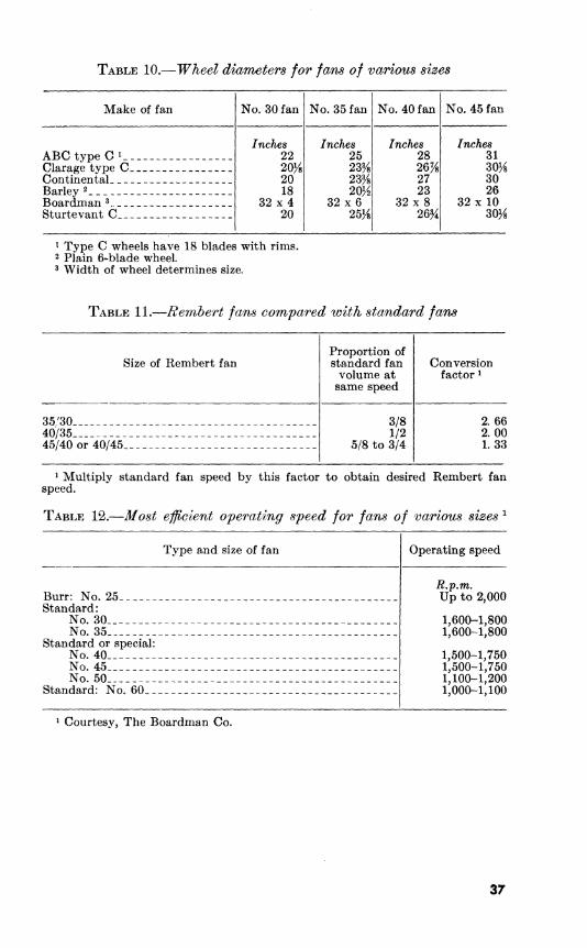
TABLE 10.—Wheel diameters for fans of various sizes
Make of fan No. 30 fan No. 35 fan No. 40 fan No. 45 fan
ABC type Gi__ Clarage type C_ Continental Barley 2 Boardman ^ Sturtevant C
Inches 22 20^8 20 18
32 X 4 20
Inches 25
23% 20/2
32 X 6 25/8
Inches 28 26K 27 23
32 X 8 26%
Inches 31 30K8 30 26
32 X 10 30K
^ Type C wheels have 18 blades with rims. 2 Plain 6-blade wheel. 3 Width of wheel determines size.
TABLE 11.—Rembert fans compared with standard fans
Size of Rembert fan Proportion of standard fan
volume at same speed
Conversion factor *
35/30 40/35 45/40 or 40/45_
3/8 1/2
5/8 to 3/4
2.66 2.00 1.33
1 Multiply standard fan speed by this factor to obtain desired Rembert fan
TABLE VI,—Most efficient operating speed for fans 0 f various sizes ^
Type and size of fan Operating speed
Burr: No. 25_-_- _ . ______ ___. R.p.m. Up to 2,000
Standard: No, 30 1,600-1,800 No. 35 1,600-1,800
Standard or special: No. 40 _ __ -- - . -_ - 1,500-1,750 No. 45 1,500-1,750 No. 50 1,100-1,200
Standard: No. 60_ _. .__.__ _____ 1,000-1,100
1 Courtesy, The Boardman Co.
37
(O 00
TABLE 13.—Volume of air delwered^ most efßcient operating speed, and brake horsepower required for most com- monly used gin fans equipped with long shavi/ngs wheels and operating against given static pressures
Item Static pressure
2 3 4 5 6 7 8 9 10 11 12 13 15
No. 30: Volume, c.f.m Speed, r.p.m Brake horsepower
No. 35: Volume, c.f.m Speed, r.p.m Brake horsepower
No. 40: Volume, c.f.m Speed, r.p.m Brake horsepower
No. 45: Volume, c.f.m Speed, r.p.m Brake horsepower
No. 50: Volume, c.f.m Speed, r.p.m Brake horsepower
1,586 1,040 0.90
2, 170 905
1. 23
2,794 800
1.58
3,526 694
2.00
4,312 631
2.43
1,982 1,285
1. 69
2,712 1, 110
2. 31
3, 492 984
2.97
4,407 850
3.75
5,390 776
4.58
2,379 1,490
2. 73
3,255 1,295
3, 74
4, 191 1, 140 4.80
5,289 990
6. 06
6,468 905
7.40
2,577 1,650 3.66
3,526 1,430 5.00
4,540 1, 266 6.45
5,730 1, 100
8. 14
7,007 1, 000 9.91
2,775 1,805 14.72
3,797 1, 570 6.45
4,889 1,390 8.30
6. 170 1,205 10. 50
7,546 1,095 12.80
2,974 1,950 5.86
4,068 1,695 8.04
5, 239 1,495 10.35
6, 610 1,300 13. 05
8,085 1, 180 15.95
3, 172 2,090
7. 16
4,340 1,805
9. 80
5,588 1, 600 12.60
7,052 1,385 15. 95
8,624 1, 265 19. 45
3,370 2, 210 8.57
4,611 1,920 11.71
5,937 1,700 15. 10
7,493 1, 470 19.05
9, 163 1,345 23.25
3,568 2, 330 10. 15
4,882 2, 025 13.90
6, 286 1,790 17.85
7,933 1,550 22. 60
9,702 1,415 27.60
3,767 2, 450 11.80
5, 153 2, 125 16.20
6,636 1,880 20.80
8,373 1,630 26.30
10, 241 1, 485 32. 10
3,965 2, 560 13.50
5,425 2, 225 18.50
6,985 1,970 23.80
8,815 1,710 30. 10
10, 780 1,555 36.70
4, 163 2, 665 15.40
5, 696 2,320 21.00
7,334 2,050 27. 10
9,256 1,775 34.20
11, 319 1,620 41.85
4,361 2,860 18. 55
5,967 2,480 25. 40
7,683 2, 190 32.70
9,696 1,900 41.30
11, 858 1,735 50.40
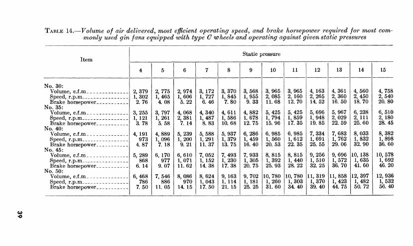
TABLE 14.—Volume of air delivered^ most efficient operating speedy and brake horsepower required for most com- ■monly used gin fans equipped with type C wheels and operating against given static pressures
Item Static pressure
10 11 12 13 14 15
No. 30: Volume, c.f.m Speed, r.p.m Brake horsepower
No. 35: Volume, c.f.m Speed, r.p.m Brake horsepower
No. 40: Volume, c.f.m Speed, r.p.m Brake horsepower
No. 45: Volume, c.f.m Speed, r.p.m Brake horsepower
No. 50: Volume, c.f.m Speed, r.p.m Brake horsepower
2,379 1,302 2.76
3,255 1, 121
3. 78
4, 191 973
4 87
5,289 868
6. 14
6,468 786
7.50
2,775 1,465 4.08
3,797 1,261 5.58
4,889 1,096
7. 18
6, 170 977
9.07
7,546 886
11.05
2,974 1,606 5.22
4,068 2,381
7. 14
5,239 1,200 9.21
6,610 1,071 11.62
8,086 970
14 15
3, 172 1,727 6.46
4,340 1,487 8.83
5,588 1,291 11.37
7,052 1, 152 14.38
8,624 1,043 17.50
3,370 1,845 7.80
4,611 1,586 10.68
5,937 1,379 13.75
7,493 1,230 17.38
9,163 1. 114 21. 15
3,568 1,955 9.33
4,882 1,678 12.75
6,286 1,459 16.40
7,933 1,305 20.75
9,702 1,181 25.25
3,965 2,085 11.68
5,425 1,794 15.96
6,985 1,560 20.53
8,815 1,392 25.93
10, 780 1,260 31.60
3,965 2, 160 12.70
5,425 1,859 17.35
6,985 1,612 22.35
8,815 1,440 28.22
10, 780 1,303 34 40
4,163 2, 265 14 52
5,696 1,948 19.85
7,334 1,691 25.55
9,256 1,510 32. 25
11, 319 1,370 39.40
4,361 2,360 16. 50
5,967 2,029 22. 59
7,683 1,762 29.06
9,696 1,572 36.70
11, 858 1,423 44 75
4,560 2,450 18.70
6,238 2, 111 25.60
8,033 1,832 32.90
10, 138 1,635 41.60
12, 397 1,482 50.72
4,758 2,540 20.80
6,510 2, 180 28.45
8,382 1,898 36.60
10, 578 1,692 46.20
12, 936 1,532 56.40
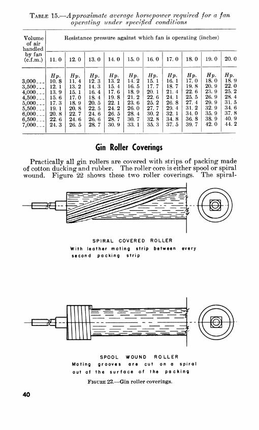
TABLE 15.—Approximate average horsepoioer required for a fan operating under specified conditions
Volume Resistance pressure against which fan is operating (inches) of air
handled by fan (c.f.m.) 11.0 12.0 13.0 14.0 15.0 16.0 17.0 18.0 19.0 20.0
Hv. Hv. Hp. Hv. Hv. Hv. Hv. Hv. Hv. Hv. 3,000 _._ 10.8 11. 4 12.3 13. 2 14. 2 15. 1 16. 1 17.0 18.0 18. 9 3,500. __ 12. 1 13.2 14.3 15. 4 16. 5 17.7 18.7 19. 8 20.9 22.0 4,000.-_ 13.9 15. 1 16.4 17.6 18.9 20. 1 21.4 22. 6 23.9 25. 2 4,500. __ 15.6 17.0 18. 4 19.8 21.2 22. 6 24. 1 25.5 26.9 28. 4 5,000.. _ 17.3 18.9 20.5 22. 1 23.6 25. 2 26.8 27. 4 29. 9 31. 5 5,500__. 19. 1 20.8 22.5 24. 2 26.0 27. 7 29. 4 31. 2 32. 9 34.6 6,000... 20.8 22.7 24.6 26.5 28. 4 30.2 32. 1 34.0 35.9 37. 8 6,500... 22.6 24.6 26.6 28. 7 30. 7 32.8 34.8 36. 8 38.9 40. 9 7,000. __ 24.3 26.5 28. 7 30. 9 33. 1 35.3 37.5 39. 7 42.0 44. 2
Gin Roller Coverings
Practically all gin rollers are covered with strips of packing made of cotton ducking and rubber. The roller core is either spool or spiral wound. Figure 22 shows these two roller coverings. The spiral-
SPIRAL COVERED ROLLER
With leather moting strip between every second packing strip
3^^
il
SPOOL WOUND ROLLER Moting grooves ore cut on a spiral
out of the surface of the pocking
FIGURE 22.—Gin roUer coverings.
40
wound roller sheds the motes and fine trash from the ginning point without the aid of moting grooves. However, repairs to the packing cover of the spool-wound roller can be made without removing all the packing.
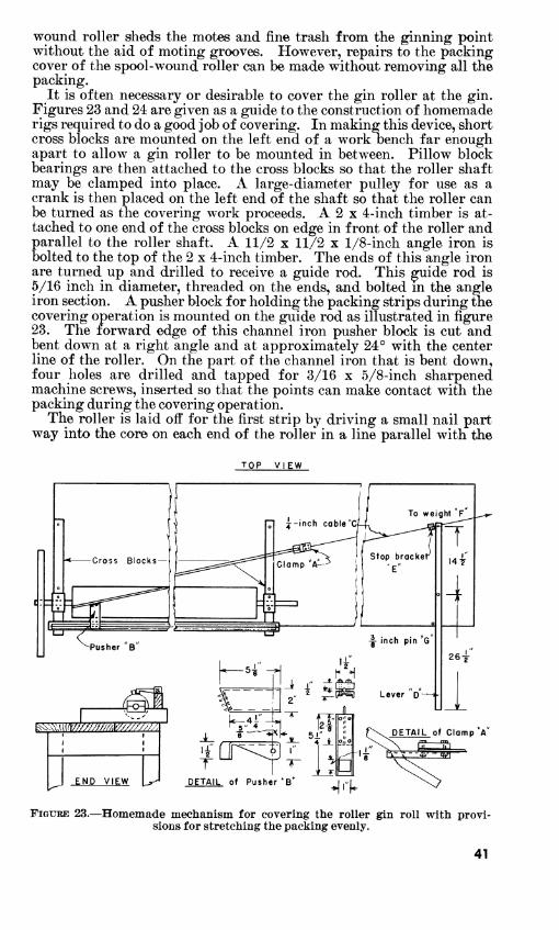
It is often necessary or desirable to cover the gin roller at the gin. Figures 23 and 24 are given as a guide to the construction of homemade rigs required to do a good job of covering. In making this device, short cross blocks are mounted on the left end of a work oench far enough apart to allow a gin roller to be mounted in between. Pillow block bearings are then attached to the cross blocks so that the roller shaft may be clamped into place. A large-diameter pulley for use as a crank is then placed on the left end of the shaft so that the roller can be turned as the covering work proceeds. A 2 x 4-inch timber is at- tached to one end of the cross blocks on edge in front of the roller and parallel to the roller shaft. A 11/2 x 11/2 x 1/8-inch angle iron is bolted to the top of the 2 x 4-inch timber. The ends of this angle iron are turned up and drilled to receive a guide rod. This guide rod is 5/16 inch in diameter, threaded on the ends, and bolted in the angle iron section. A pusher block for holding the packing strips during the covering operation is mounted on the guide rod as illustrated in figure 23. The forward edge of this channel iron pusher block is cut and bent down at a right angle and at approximately 24° with the center line of the roller. On the part of the channel iron that is bent down, four holes are drilled and tapped for 3/16 x 5/8-inch sharpened machine screws, inserted so that the points can make contact with the packing during the covering operation.
The roller is laid off for the first strip by driving a small nail part way into the core on each end of the roller in a line parallel with the
TOP VIEW
i^v\vu(/Fyy/y/yyy///ky//////7/j
£NP VI^W
T I ^ DETAIL of Pusher *B*
FIGURE 23.—Homemade mechanism for covering the roUer gin roU with provi- sions for stretching the packing evenly.
41
roller shaft. A string is tied to one nail and passed around the roller core to the other nail making one complete spiral turn. This estab- lishes a line position for the first packing strip. Glue is applied to the roller core along the positioning line. The packing covering is started by nailing one end of the strip at the left end of the roller over the glue. The packing is then spiraled around the roller and secured at the other end. IS'ails are put tlirough the strip every 3 or 4 inches to hold it firmly in position as a guide for the succeeding spiral. After two strips have been attached tliis Avay, the succeeding strips are started at the left end and the pusher block is wedged between the angle guide and the packing strip. By pulling the roller forward the packing is forced tightly against the two strips that are on the roller. The pusher block is moved to the right as strips are progres- sively nailed.
Some mechanical device should be provided to maintain uniform tension on each strip as it is wound on the roller. Such a device for a 60-pound weight is shown in figure 23. Clamp A (fig. 23) is attached to cable C which passes over a small pulley and is fastened to weight F, which is free to move up or down. The arm of lever D is moved to the right and fixed with the pin G, which raises the weight and
TOP VIEW
Press wheel
END VIEW
FIGURE 24.—Mechanism for beveling the sides of the packing strips.
42
allows clamp A to be slipped on the packing strip to about 6 inches from the right end of the roll. Pin G is then removed to allow the weight to exert its force on the strip. The roller is then turned one revolution and the packing nailed to the other or right end of the roller. The arm of the lever is then moved back to the right, releasing the pull of the weight and the packing is cut oiï. Then the strip which has just been laid on is nailed to the roller using pusher block B to press it firmly against the previous strip. Glue is applied generously with a 1-inch brush before the laying of each strip. Care should be taken, however, not to apply so much glue that it will squeeze up be- tween the packing strip and cause trouble during ginning.
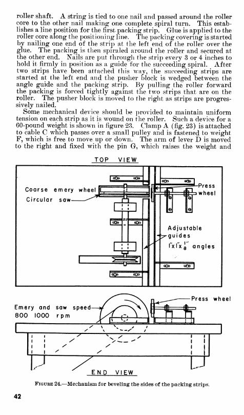
In order to place the packing on the roller so that the strips will lie close together, it is necessary to bevel the side of the strips. It is a tedious and difficult job with a jack plane. The mechanism shown in figure 24 has been employed successfully. It consists of a coarse emery wheel, adjustable guides, and a small press wheel to hold the strip down while the emery wheel is beveling the strip. A circular saw is placed to the side of the emery wheel to make the first rough cut, thus relieving the load on the emery wheel so that it makes only the finish- ing smooth cut. The saw should be slightly smaller in diameter than the emery wheel. A speed of 800 to 1,000 r.p.m. is recommended be- cause the emery wheel has a tendency to clog up and burn the ma- terial at higher speeds.
Seed Cotton Reclaimers
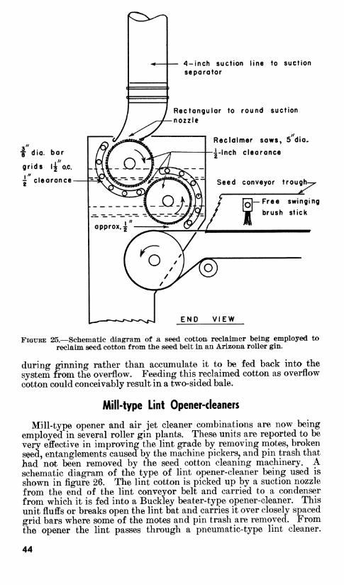
The most prevalent variety of American-Egyptian cotton grown is Pima SI. It has a semifuzzy seed, which presents a problem in clearing the seed away from the ginning point fast enough without dropping some seed cotton into the seed disposal system. Ginning capacity can be increased by moving the seed fingertips back from the moving knife and by using a seed grid with the fingers spaced as much as three-eighths inch apart; however, with this adjustment consider- able seed cotton is dropped into the seed. This seed cotton is then reclaimed by a unit at the end of a battery of gins and fed back into the suction line. Figure 25 is a schematic diagram of one such unit being successfully employed in an Arizona roller gin. The seed and seed cotton are being carried by a conveyor belt under the stands to a seed dropper at the end of each battery. During the travel down the belt, the seed tends to settle out leaving the seed cotton riding free on top of the seed. This seed cotton is picked up by a reclaimer saw and scrubbed over %-inch grid bars spaced approximately 11/^ inches on centers with V^-inch clearance between the grid bars and the reclaimer saws. The seed dislodged by the first saw falls back onto the conveyor belt and that dislodged by the second saw drops through a sheet metal shoot directly into the seed dropper. The reclaimed seed cotton is sucked off the upper saw by a direct suction to the suction line separator immediately before the separator.
When a small-pipe pneumatic seed line is used, the seed and seed cotton from the auger system can be passed through a reclaimer unit between the auger outlet and the seed dropper. Since some of the seed cotton dropped by the seed fingers is hard lock or immature cotton, it is advisable to feed the reclaimed cotton back into the system
43
4-inch suction line to suction separator
Rectangular to round suction nozzle
j dia. bar
grids \j o.e.
^ clearance
Reclaimer saws, 5 dia.
^-inch clearance
Seed conveyor trough-
FiQURE 25.—Schematic diagram of a seed cotton reclaimer being employed to reclaim seed cotton from the seed belt in an Arizona roller gin.
during ginning rather than accumulate it to be fed back into the system from the overflow. Feeding this reclaimed cotton as overflow cotton could conceivably result in a two-sided bale.
Mill-type Lint Opener-cleaners
Mill-type opener and air jet cleaner combinations are now being employed in several roller gin plants. These units are reported to be very effective in improving the lint grade by removing motes, broken seed, entanglements caused by the machine pickers, and pin trash that had not been removed by the seed cotton cleaning machinery. A schematic diagram of the type of lint opener-cleaner being used is shown in figure 26. The lint cotton is picked up by a suction nozzle from the end of the lint conveyor belt and carried to a condenser from which it is fed into a Buckley beater-type opener-cleaner. This unit fluffs or breaks open the lint bat and carries it over closely spaced grid bars where some of the motes and pin trash are removed. From the opener the lint passes through a pneumatic-type lint cleaner.
44
r\
ífs
r^
Condenser suction fans
Lint conveyor bell
i :z-
y
Suction r^ condensers
Pneumatic lint cleaner.
ffS
To press condenser
Mill type jSJi opener cleaner —
Suction nozzle '^rash
%
O) 'Trash
Fl' XÎ \
Booster tons Trash
FiGUKE 26.—Schematic diagram of the mill-type opener-cleail,er used in some of today's roller gins.
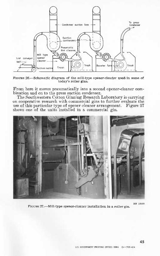
From here it moves pneumatically into a second opener-cleaner com- bination and on to the press suction condenser.
The Southwestern Cotton Ginning Eesearch Laboratory is carrying on cooperative research with commercial gins to further evaluate the use of this particular type of opener-cleaner arrangement. Figure 27 shows one of the units installed in a commercial gin.
FiGUBE 27.—Mill-type opener-cleaner installation in a roller gin.
45 U.S. GOVERNMENT PRINTrNG OFFICE : 1964 O—705-424