Embed Size (px)
Citation preview
DRVE-DS-01-F-EN 1
Operations and maintenance
manual
Roller doors
DRVE-DS-01-F-EN 2
Content
General safety precautions ..................................................................................................................... 3
General information ............................................................................................................................. 3
Warnings ................................................................................................................................................ 3
Roller door use ..................................................................................................................................... 4
Overview of the industries in which the roller doors can be used: ............................................... 4
Limited use ............................................................................................................................................ 4
Unpacking .............................................................................................................................................. 4
Mounting the roller door ...................................................................................................................... 4
Power-up of automatic door................................................................................................................ 4
Disposal ................................................................................................................................................. 5
General information about roller doors ................................................................................................. 5
Technical specifications ...................................................................................................................... 5
Roller door projection ........................................................................................................................... 6
Definition of wall opening measurements and frame measurements ........................................ 10
Functional descriptions (options) ......................................................................................................... 11
Control panel ....................................................................................................................................... 11
Pull chord ............................................................................................................................................. 11
Radar .................................................................................................................................................... 11
Radio control ....................................................................................................................................... 12
Induction loop ...................................................................................................................................... 12
Rat protection ...................................................................................................................................... 12
Other options ....................................................................................................................................... 12
Operations and maintenance ............................................................................................................... 13
Repairing faults ....................................................................................................................................... 14
Spare part list .......................................................................................................................................... 15
DRVE-DS-01-F-EN 3
General safety precautions
General information
This operations and maintenance manual applies automatic roller doors and must be read carefully before putting the door into operation. Be particularly attentive to the safety information. Door users must be thoroughly instructed in the use of the door. It is important to adhere to the service intervals to achieve the longest possible service life. Roller doors should be serviced by authorised service engineers.
There is a compulsory annual service inspection for roller doors.
Warnings
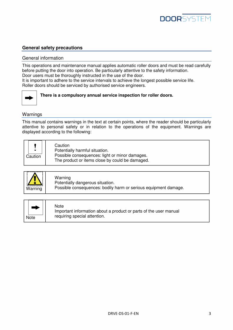
This manual contains warnings in the text at certain points, where the reader should be particularly attentive to personal safety or in relation to the operations of the equipment. Warnings are displayed according to the following:
Caution
Caution Potentially harmful situation. Possible consequences: light or minor damages. The product or items close by could be damaged.
Warning
Warning Potentially dangerous situation. Possible consequences: bodily harm or serious equipment damage.
Note
Note Important information about a product or parts of the user manual requiring special attention.
DRVE-DS-01-F-EN 4
Roller door use
The roller door can be used in all kinds of industry to separate 2 rooms, with a need for quick open/close time. This may be due to differences in temperature, pressure, draft or obnoxious smells. In principle, there are no limits as to how often the door is opened and closed, however, the time intervals between service and maintenance may vary depending on the door usage. The door can be operated by a push-button signal or a signal from various remote controls. The door has vertical opening and closing and can solely be fitted as such.
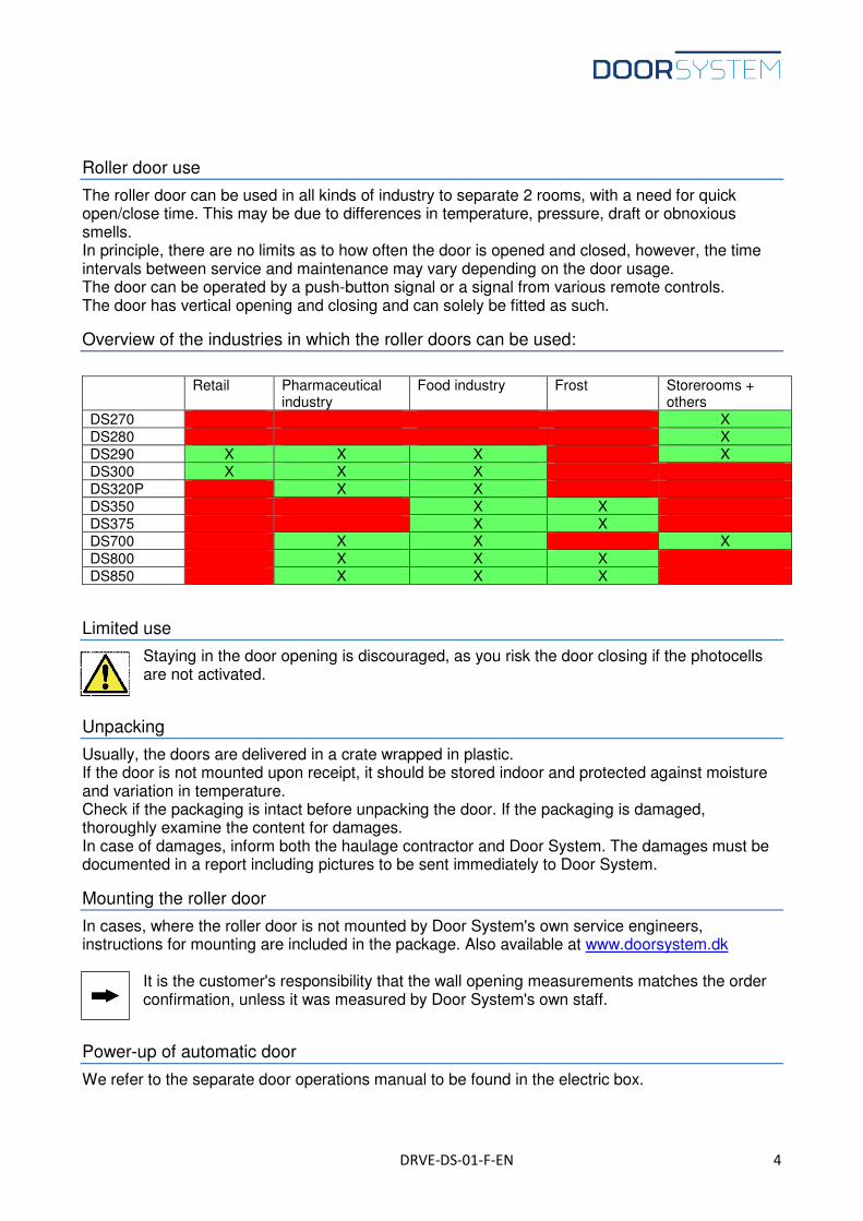
Overview of the industries in which the roller doors can be used:
Retail Pharmaceutical
industry Food industry Frost Storerooms +
others DS270 X DS280 X DS290 X X X X DS300 X X X DS320P X X DS350 X X DS375 X X DS700 X X X DS800 X X X DS850 X X X
Limited use
Staying in the door opening is discouraged, as you risk the door closing if the photocells are not activated.
Unpacking
Usually, the doors are delivered in a crate wrapped in plastic. If the door is not mounted upon receipt, it should be stored indoor and protected against moisture and variation in temperature. Check if the packaging is intact before unpacking the door. If the packaging is damaged, thoroughly examine the content for damages. In case of damages, inform both the haulage contractor and Door System. The damages must be documented in a report including pictures to be sent immediately to Door System.
Mounting the roller door
In cases, where the roller door is not mounted by Door System's own service engineers, instructions for mounting are included in the package. Also available at www.doorsystem.dk
It is the customer's responsibility that the wall opening measurements matches the order confirmation, unless it was measured by Door System's own staff.
Power-up of automatic door
We refer to the separate door operations manual to be found in the electric box.
DRVE-DS-01-F-EN 5
Disposal
The door must be disposed of according to the national environmental legislation and regulations in force at the time in question.
General information about roller doors
A roller door comprises of 2 frame legs, a top rail, a door leaf, shielding and a control box. The various models are developed for storerooms/shops, for moderate hygiene demands, high hygiene demands and demands in pressure difference as well as for freezer rooms.
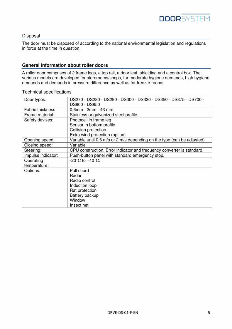
Technical specifications
Door types: DS270 - DS280 - DS290 - DS300 - DS320 - DS350 - DS375 - DS700 - DS800 - DS850
Fabric thickness: 0,6mm - 2mm - 43 mm Frame material: Stainless or galvanized steel profile. Safety devises: Photocell in frame leg
Sensor in bottom profile Collision protection Extra wind protection (option)
Opening speed: Variable until 0,6 m/s or 2 m/s depending on the type (can be adjusted) Closing speed: Variable Steering: CPU construction. Error indicator and frequency converter is standard. Impulse indicator: Push-button panel with standard emergency stop. Operating temperature:
-20°C to +40°C.
Options: Pull chord Radar Radio control Induction loop Rat protection Battery backup Window Insect net
DRVE-DS-01-F-EN 6
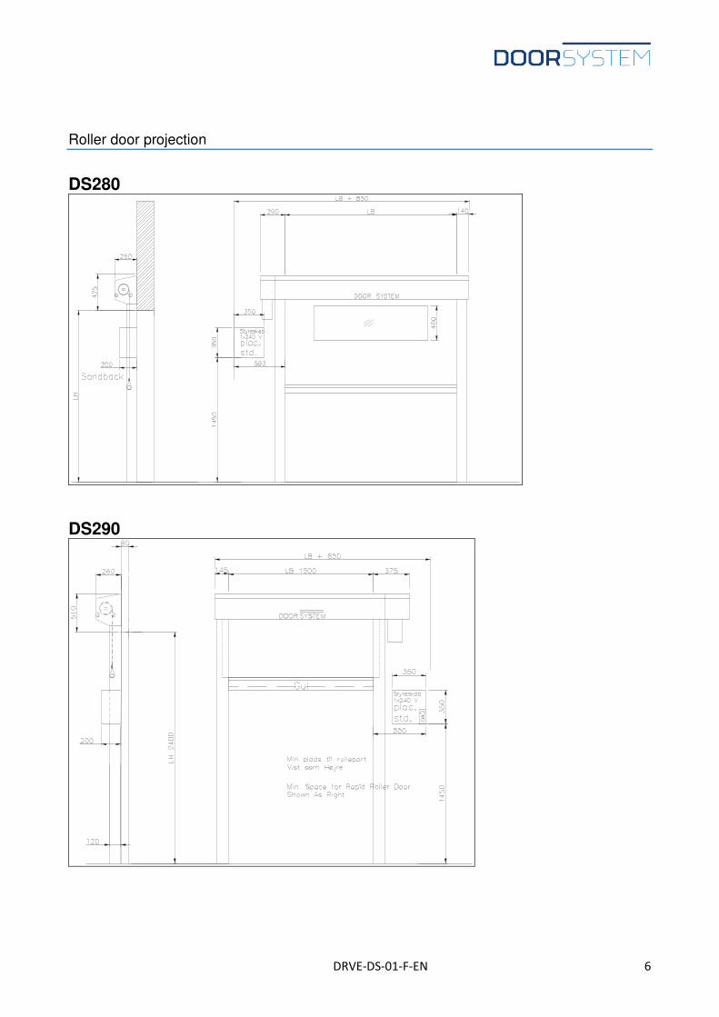
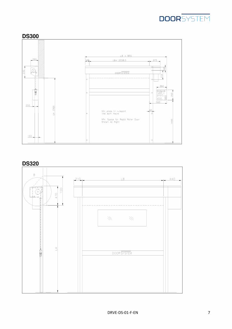
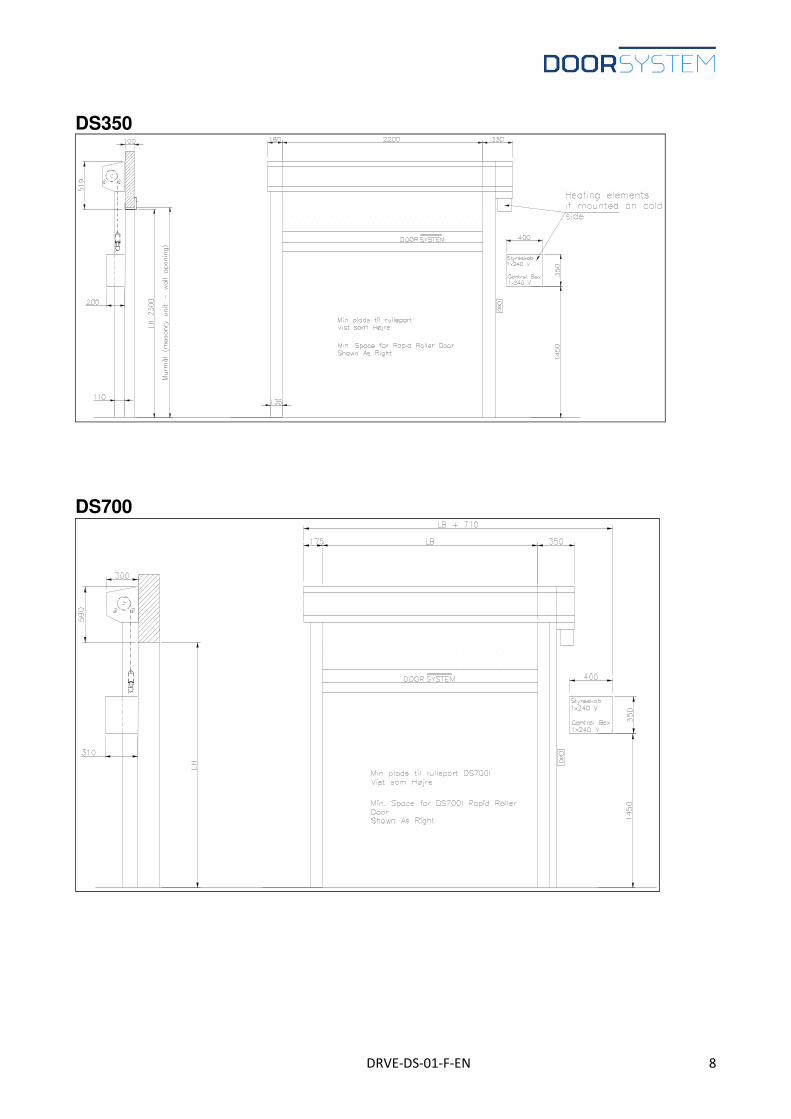
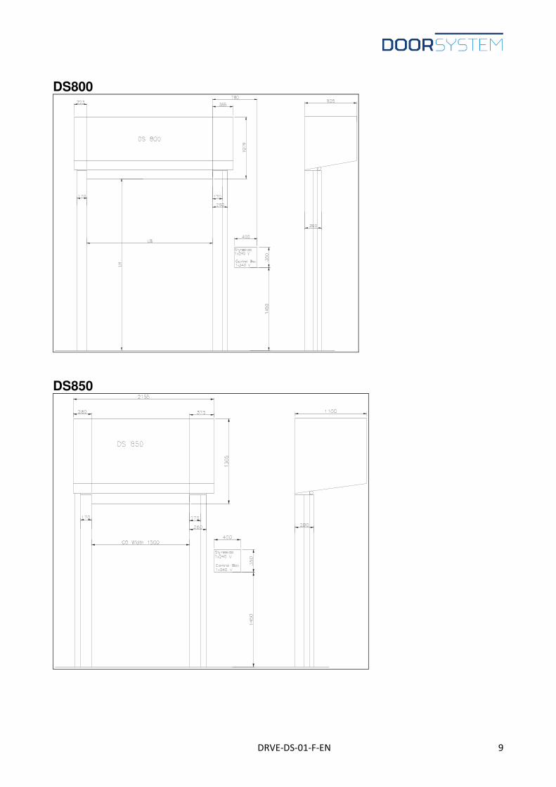
Roller door projection
DS280
DS290
DRVE-DS-01-F-EN 7
DS300
DS320
DRVE-DS-01-F-EN 8
DS350
DS700
DRVE-DS-01-F-EN 9
DS800
DS850
DRVE-DS-01-F-EN 10
lysning
lysning
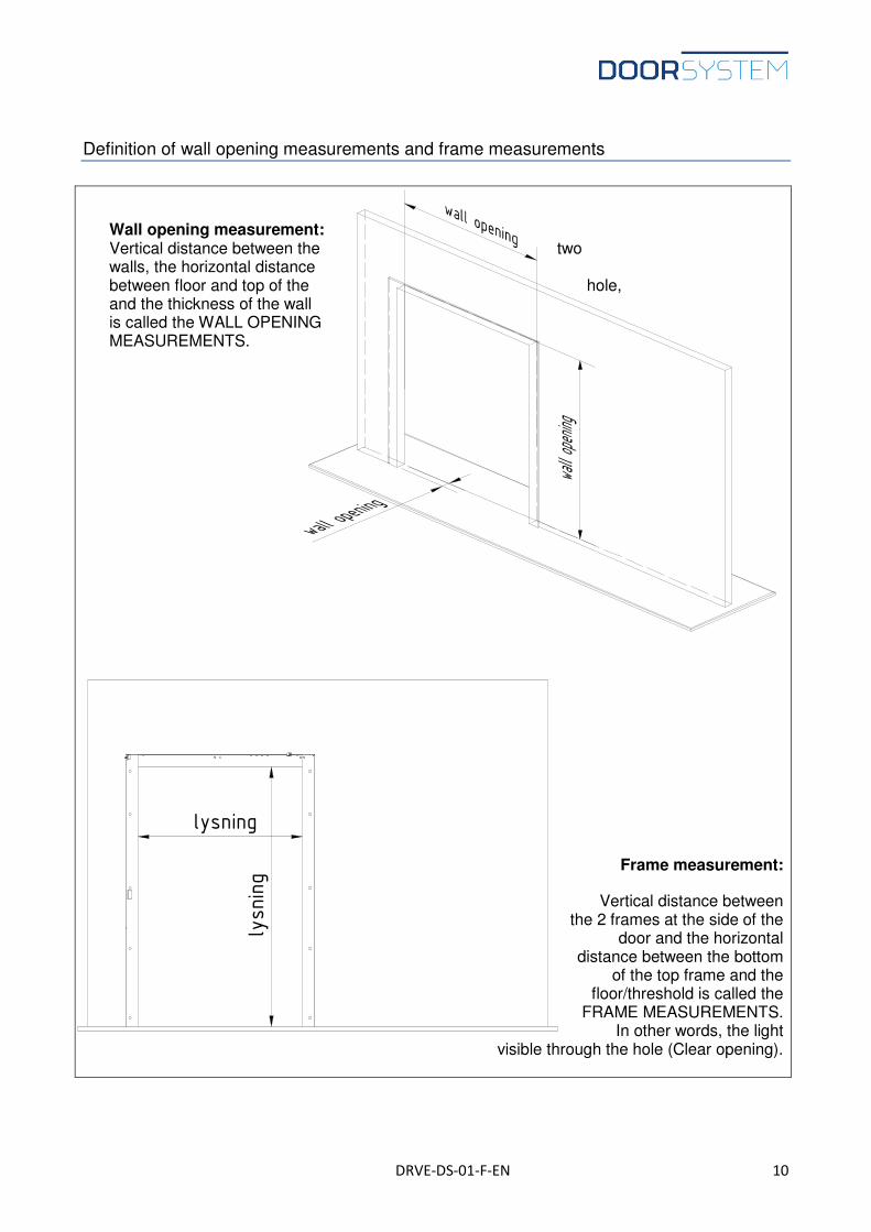
Definition of wall opening measurements and frame measurements
Wall opening measurement: Vertical distance between the two walls, the horizontal distance between floor and top of the hole, and the thickness of the wall is called the WALL OPENING MEASUREMENTS.
Frame measurement:
Vertical distance between the 2 frames at the side of the
door and the horizontal distance between the bottom
of the top frame and the floor/threshold is called the
FRAME MEASUREMENTS. In other words, the light
visible through the hole (Clear opening).
DRVE-DS-01-F-EN 11
Functional descriptions (options)
Control panel
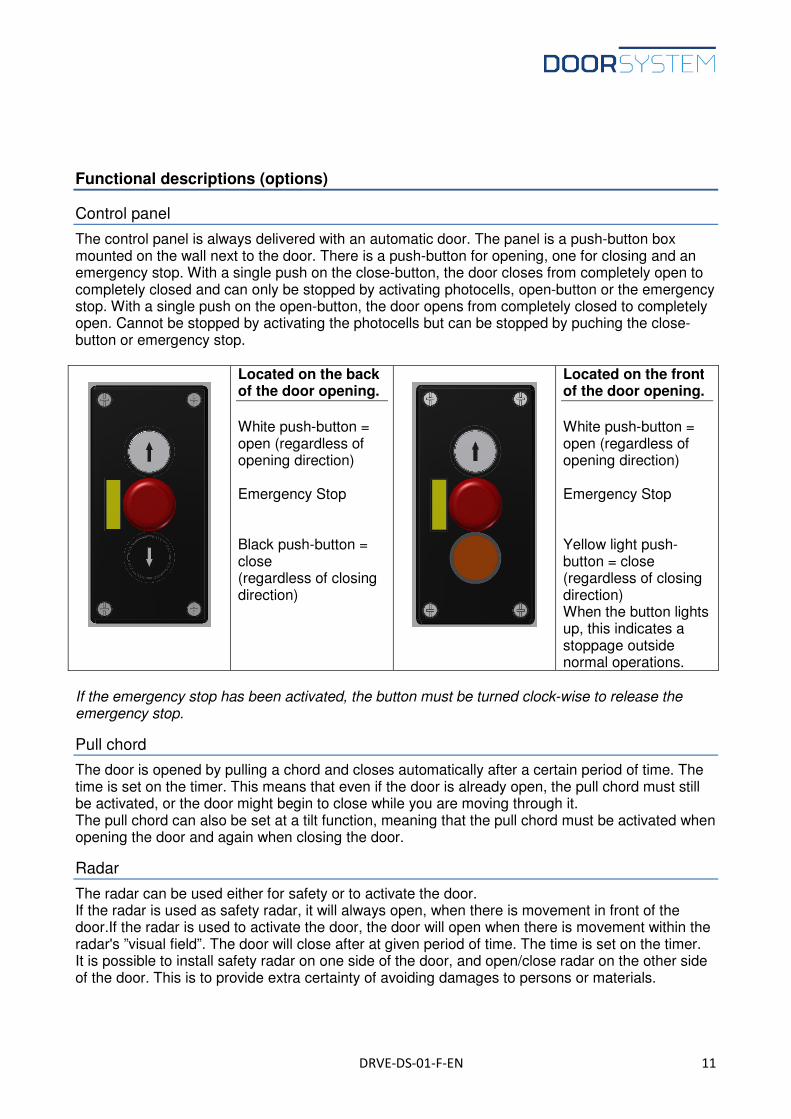
The control panel is always delivered with an automatic door. The panel is a push-button box mounted on the wall next to the door. There is a push-button for opening, one for closing and an emergency stop. With a single push on the close-button, the door closes from completely open to completely closed and can only be stopped by activating photocells, open-button or the emergency stop. With a single push on the open-button, the door opens from completely closed to completely open. Cannot be stopped by activating the photocells but can be stopped by puching the close-button or emergency stop.
Located on the back of the door opening.
White push-button = open (regardless of opening direction) Emergency Stop Black push-button = close (regardless of closing direction)
Located on the front of the door opening.
White push-button = open (regardless of opening direction) Emergency Stop Yellow light push-button = close (regardless of closing direction) When the button lights up, this indicates a stoppage outside normal operations.
If the emergency stop has been activated, the button must be turned clock-wise to release the emergency stop.
Pull chord
The door is opened by pulling a chord and closes automatically after a certain period of time. The time is set on the timer. This means that even if the door is already open, the pull chord must still be activated, or the door might begin to close while you are moving through it. The pull chord can also be set at a tilt function, meaning that the pull chord must be activated when opening the door and again when closing the door.
Radar
The radar can be used either for safety or to activate the door. If the radar is used as safety radar, it will always open, when there is movement in front of the door.If the radar is used to activate the door, the door will open when there is movement within the radar's ”visual field”. The door will close after at given period of time. The time is set on the timer. It is possible to install safety radar on one side of the door, and open/close radar on the other side of the door. This is to provide extra certainty of avoiding damages to persons or materials.
DRVE-DS-01-F-EN 12
Radio control
Radio control is a remote control of the door, often utilised in locations with truck traffic.
Induction loop
Magnetic field, which is buried in the floor. It registers when metal enters the area and opens the door. The door will close after at certain period of time. The time is set on the timer.
Rat protection
Also known as ”rat mode”. A time setting in the control ensuring that the door closes completely when it has been inactive for a certain period of time. Often used in slaughterhouses.
Other options
It is possible to deliver the door with the following: - Battery backup: Used when you wish to operate the door during power failure. - Window: A piece of the door leaf is replaced with a plastic window. This is useful when you
wish to be able to look through the door. - Insect net: A piece of the door leaf is replaced with an insect net. This is useful when you
desire a sound air flow between two rooms.
DRVE-DS-01-F-EN 13
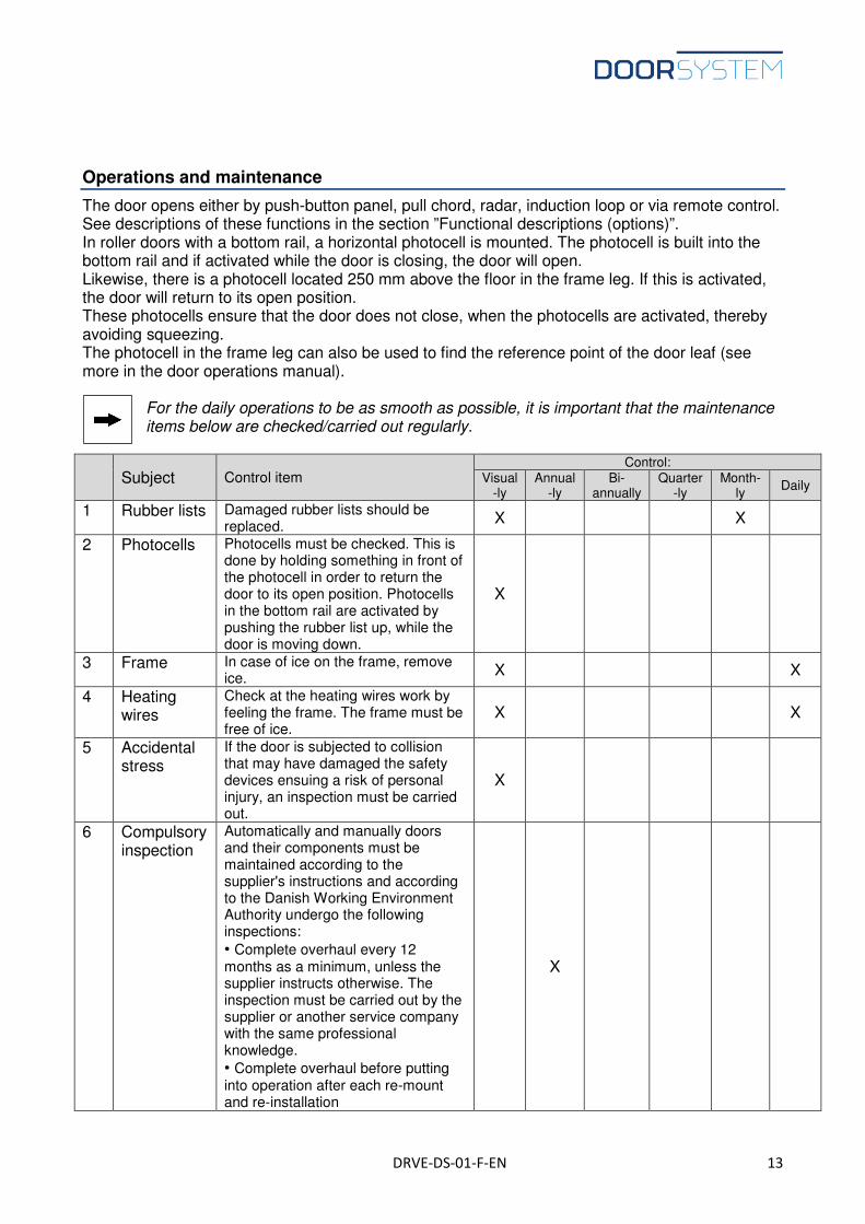
Operations and maintenance
The door opens either by push-button panel, pull chord, radar, induction loop or via remote control. See descriptions of these functions in the section ”Functional descriptions (options)”. In roller doors with a bottom rail, a horizontal photocell is mounted. The photocell is built into the bottom rail and if activated while the door is closing, the door will open. Likewise, there is a photocell located 250 mm above the floor in the frame leg. If this is activated, the door will return to its open position. These photocells ensure that the door does not close, when the photocells are activated, thereby avoiding squeezing. The photocell in the frame leg can also be used to find the reference point of the door leaf (see more in the door operations manual).
For the daily operations to be as smooth as possible, it is important that the maintenance items below are checked/carried out regularly.
Subject Control item
Control: Visual
-ly Annual
-ly Bi-
annually Quarter
-ly Month-
ly Daily
1 Rubber lists Damaged rubber lists should be replaced.
X X
2 Photocells Photocells must be checked. This is done by holding something in front of the photocell in order to return the door to its open position. Photocells in the bottom rail are activated by pushing the rubber list up, while the door is moving down.
X
3 Frame In case of ice on the frame, remove ice.
X X
4 Heating wires
Check at the heating wires work by feeling the frame. The frame must be free of ice.
X X
5 Accidental stress
If the door is subjected to collision that may have damaged the safety devices ensuing a risk of personal injury, an inspection must be carried out.
X
6 Compulsory inspection
Automatically and manually doors and their components must be maintained according to the supplier's instructions and according to the Danish Working Environment Authority undergo the following inspections:
• Complete overhaul every 12 months as a minimum, unless the supplier instructs otherwise. The inspection must be carried out by the supplier or another service company with the same professional knowledge.
• Complete overhaul before putting into operation after each re-mount and re-installation
X
DRVE-DS-01-F-EN 14
Subject Control item
Control: Visual
ly Annual
ly Bi-
annually Quarter
ly Month
ly Dai ly
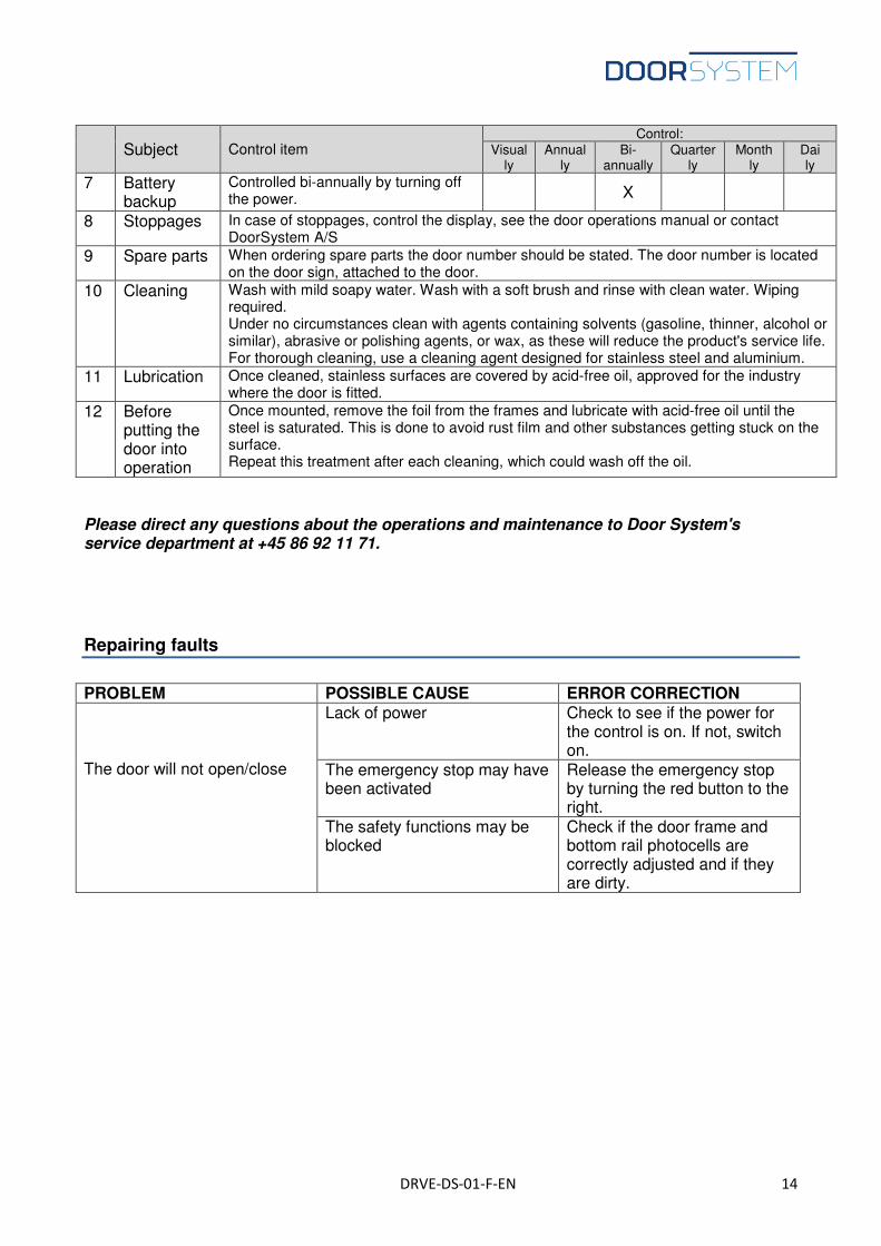
7 Battery backup
Controlled bi-annually by turning off the power. X
8 Stoppages In case of stoppages, control the display, see the door operations manual or contact DoorSystem A/S
9 Spare parts When ordering spare parts the door number should be stated. The door number is located on the door sign, attached to the door.
10 Cleaning Wash with mild soapy water. Wash with a soft brush and rinse with clean water. Wiping required. Under no circumstances clean with agents containing solvents (gasoline, thinner, alcohol or similar), abrasive or polishing agents, or wax, as these will reduce the product's service life. For thorough cleaning, use a cleaning agent designed for stainless steel and aluminium.
11 Lubrication Once cleaned, stainless surfaces are covered by acid-free oil, approved for the industry where the door is fitted.
12 Before putting the door into operation
Once mounted, remove the foil from the frames and lubricate with acid-free oil until the steel is saturated. This is done to avoid rust film and other substances getting stuck on the surface. Repeat this treatment after each cleaning, which could wash off the oil.
Please direct any questions about the operations and maintenance to Door System's service department at +45 86 92 11 71.
Repairing faults
PROBLEM POSSIBLE CAUSE ERROR CORRECTION The door will not open/close
Lack of power Check to see if the power for the control is on. If not, switch on.
The emergency stop may have been activated
Release the emergency stop by turning the red button to the right.
The safety functions may be blocked
Check if the door frame and bottom rail photocells are correctly adjusted and if they are dirty.
DRVE-DS-01-F-EN 15
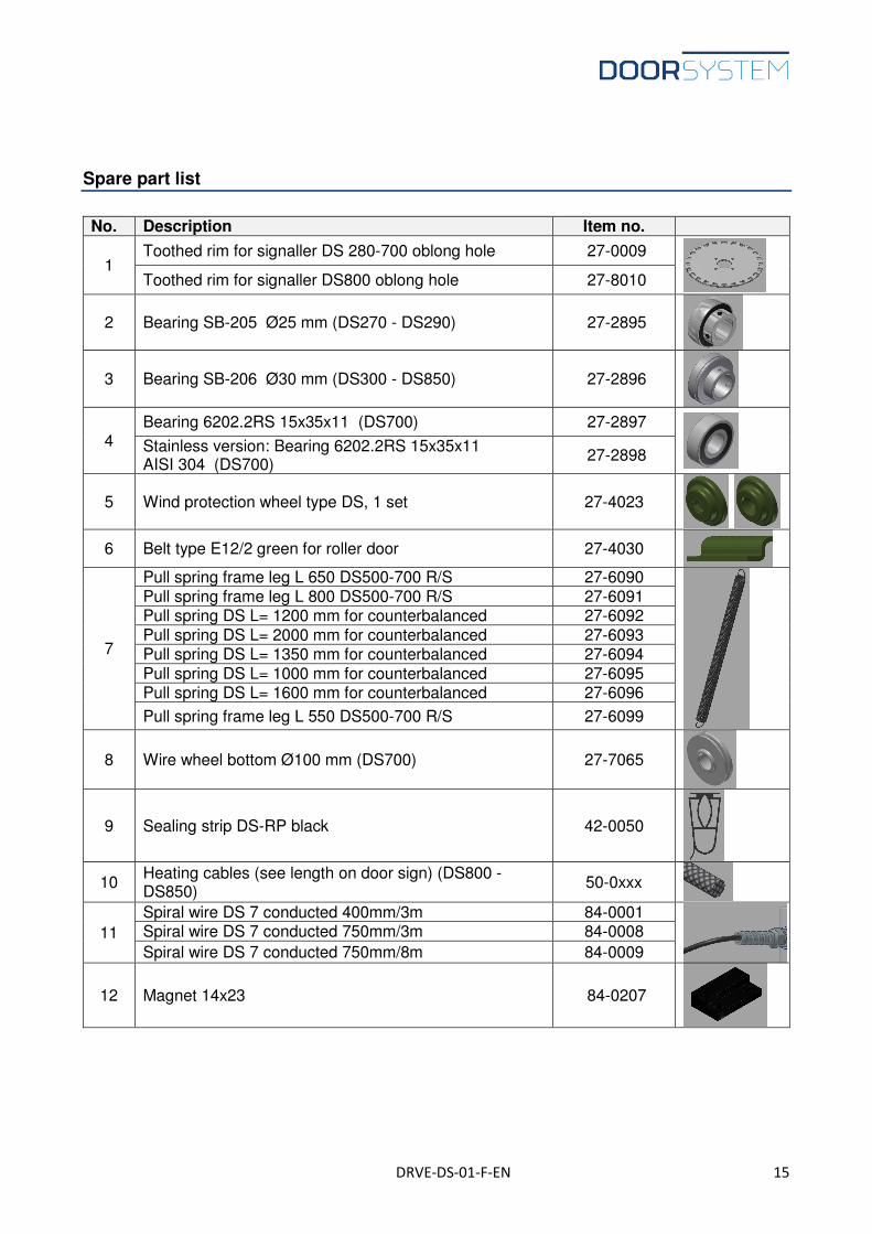
Spare part list
No. Description Item no.
1 Toothed rim for signaller DS 280-700 oblong hole 27-0009
Toothed rim for signaller DS800 oblong hole 27-8010
2 Bearing SB-205 Ø25 mm (DS270 - DS290) 27-2895
3 Bearing SB-206 Ø30 mm (DS300 - DS850) 27-2896
4 Bearing 6202.2RS 15x35x11 (DS700) 27-2897
Stainless version: Bearing 6202.2RS 15x35x11 AISI 304 (DS700)
27-2898
5 Wind protection wheel type DS, 1 set 27-4023
6 Belt type E12/2 green for roller door 27-4030
7
Pull spring frame leg L 650 DS500-700 R/S 27-6090
Pull spring frame leg L 800 DS500-700 R/S 27-6091 Pull spring DS L= 1200 mm for counterbalanced 27-6092 Pull spring DS L= 2000 mm for counterbalanced 27-6093 Pull spring DS L= 1350 mm for counterbalanced 27-6094 Pull spring DS L= 1000 mm for counterbalanced 27-6095 Pull spring DS L= 1600 mm for counterbalanced 27-6096
Pull spring frame leg L 550 DS500-700 R/S 27-6099
8 Wire wheel bottom Ø100 mm (DS700) 27-7065
9 Sealing strip DS-RP black 42-0050
10 Heating cables (see length on door sign) (DS800 - DS850)
50-0xxx
11
Spiral wire DS 7 conducted 400mm/3m 84-0001
Spiral wire DS 7 conducted 750mm/3m 84-0008
Spiral wire DS 7 conducted 750mm/8m 84-0009
12 Magnet 14x23 84-0207
DRVE-DS-01-F-EN 16
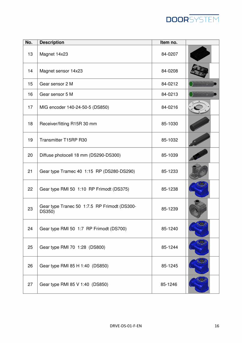
No. Description Item no.
13 Magnet 14x23 84-0207
14 Magnet sensor 14x23 84-0208
15 Gear sensor 2 M 84-0212
16 Gear sensor 5 M 84-0213
17 MIG encoder 140-24-50-5 (DS850) 84-0216
18 Receiver/fitting R15R 30 mm 85-1030
19 Transmitter T15RP R30 85-1032
20 Diffuse photocell 18 mm (DS290-DS300) 85-1039
21 Gear type Tramec 40 1:15 RP (DS280-DS290) 85-1233
22 Gear type RMI 50 1:10 RP Frimodt (DS375) 85-1238
23 Gear type Tranec 50 1:7.5 RP Frimodt (DS300-DS350)
85-1239
24 Gear type RMI 50 1:7 RP Frimodt (DS700) 85-1240
25 Gear type RMI 70 1:28 (DS800) 85-1244
26 Gear type RMI 85 H 1:40 (DS850) 85-1245
27 Gear type RMI 85 V 1:40 (DS850) 85-1246
DRVE-DS-01-F-EN 17
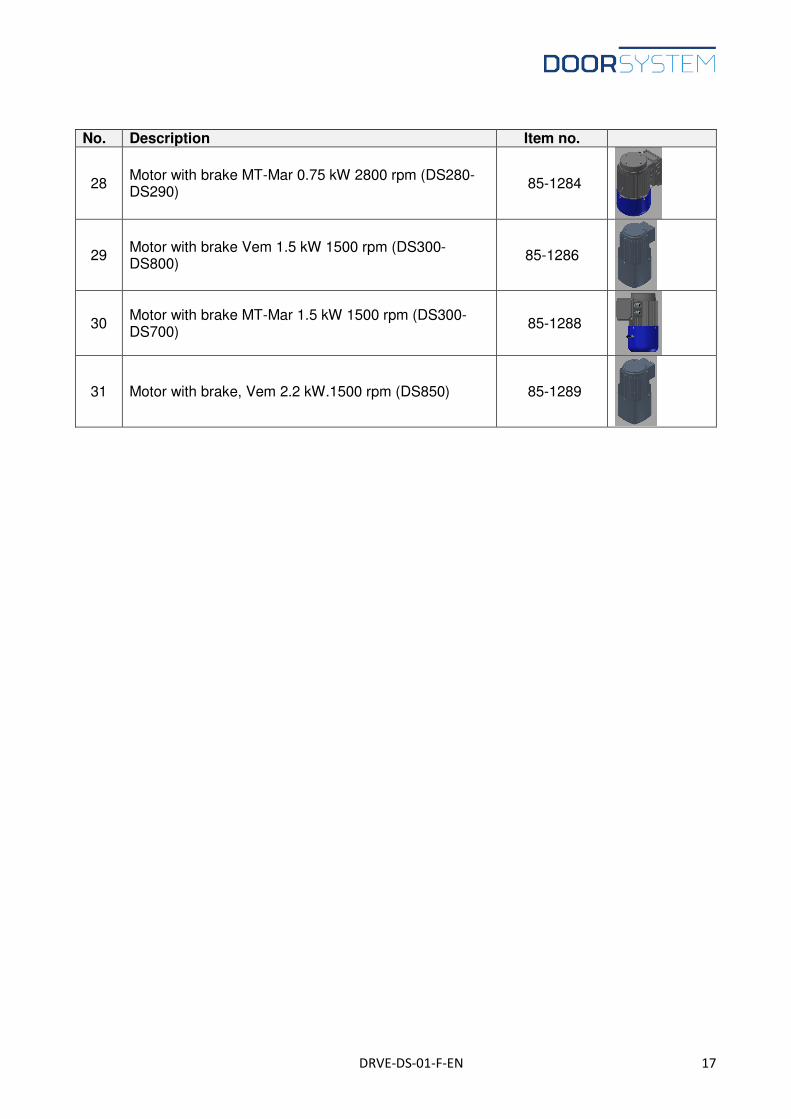
No. Description Item no.
28 Motor with brake MT-Mar 0.75 kW 2800 rpm (DS280-DS290)
85-1284
29 Motor with brake Vem 1.5 kW 1500 rpm (DS300-DS800)
85-1286
30 Motor with brake MT-Mar 1.5 kW 1500 rpm (DS300-DS700)
85-1288
31 Motor with brake, Vem 2.2 kW.1500 rpm (DS850) 85-1289