Embed Size (px)
Citation preview

SEPTEMBER 2OTH, 1945 FLIGHT
•ROLLS-ROYCEGRIFFON
(65)Review of the Latest
^Rolls-Royce Piston Engine :Classic Orthodoxy of DesignPowers Yet Achieved
Highest Specific
WHEN confronted with the Rolls-Royce Griffon forthe first time, the facile result of an initial rapidappraisal is that the engine is nothing much more
than a scaled-np Merlin, and, although there is doubtless acertain amount of justification for this view, it is not whollyaccurate. In actual fact, as one's investigations progress,the impression is steadily strengthened that, far from beingmerely a scale-up of an existing engine, the Griffon is anentirely new engine in its own right. I t would, however,probably be pretty accurate to hazard the assumption thatthe Griffon was born of a desire to redesign the Merlin,eliminating all the snags and, at the same time, increasethe capacity to meet the imminent demand for a largerengine whilst retaining the smallest overall dimensionspossible.
How well the men of Derby have succeeded in doingwhat they set out to do may be appreciated in part by acomparison of overall dimensions as between Griffon andMerlin, together with the respective swept volumes andpiston areas. In overall length the Griffon 65 is 8iin.,three inches longer than the 78m. of the equivalent Merlin,the 66; overall heights are respectively, Griffon, 45111., andMerlin, 43.675111., whilst the overall widths are: Griffon
„ BEARINGVENT PIPE
29.5m., and Merlin 2y.825in. It would seem well-nighimpossible, ,011 the face of it, that with such similarity ofoverall dimensions in two engines of the same basic type,the swept volume of one should be 35.9 per cent, largerthan that of the other. Such, however, is the case. Pistonarea of the Griffon is 23 per cent, greater than that of theMerlin, this having been achieved by increasing the cylinderbore to 6oin. : a figure which is just about verging onthe optimum limit.
In view of this one is led to wonder what form theGriffon's successor will take; the useful limit of pistondiameter halving been reached, one is forced to the conclu-sion that any largar capacity piston engine that Rolls havein m^nd to follow the Griffon will, of necessity, have morecylinders. It is an interesting speculation which naturally,and on precedent, takes it for granted that Derby do intendto produce a new and bigger orthodox engine.
Influence of the Racing ' ' Buzzard ' 'Before going on to deal with the Griffon, a word should
be said on the prevalent and somewhat erroneous assump-tion that the engine is a counterpart of the famous " R "special Buzzard racing engine which secured the Schneider
Trophy for England in 1929 and 1931, andestablished a World's Speed Record. Certainly,the bore and stroke size are the same and so isthe fundamental layout of the engine—but therethe similarity ends. I t can truthfully be saidthat the lessons learned on the " R " enginehave had their influence on all the subsequentRolls engines, but equally, the knowledgegained in the Merlin has resulted in the refine-ments which distinguish the Griffon. The oneparticular feature which the feriffon owesdirectly to the " R " is the crankshaft, for theamount of development put into this memberon the racing engine virtually paved the waytowards making the Griffon a success fromthe very beginning of its life.
It is not, perhaps, gener-ally known that theGriffon was" originally de-veloped primarily to meetthe Fleet Air Arm's specific-needs—low-altitude power,ease of service, reliability,etc. In the early days of
7Induction throatto impellers show-ing turbulencespider with fuel
nozzles.
FLIGHT v
LENGTH . . .. 8lin.(to airscrew rear cone)
HEIGHT
WIDTH
DRY WEIGHT
MAX. B.H.P.
FRONTAL
Bare engine . .
Installed (Spitfire
. . 45in.
. . 29.5in.
2,0901b.
. . 2,220
AREA
7.9 sq.ft.
XIV)11 sq. ft.
ROLi*TACHOMETER
DRIVE
AUXIIJARYGEARBOX
DRIVE
CONSTANTSPEED UNIT
MOUNTING FACE
INTERCOOLER
INDUCTION TRUNK.DELIVERING TO
CYLINDER BLOCKSWET
CYLINDER LINERS
INTER-STAGECOOLANT CONNECTIONS
TOAIRCRAFT RADIATORS
INTER-STAGECOOLINGPASSAGE -
HONEYCOMBBLOCK
ACCELERATOR PUMPINIECTOR NOZZLE
INJECTORFUEL NOZZLE
TURBULENCESPIDER
SUPERCHARGERIMPELLERS
THREE-BARRELTHROTTLE
ENTHYSUPERCHARGERCHANGESP6ED | N T E R C O O L E R
COOLANTPUMP
SCAVENGE FOUROIL FILTERS
ROLLS-ROYCEBENDIX-STROMBERG
INJECTOR TYPECARBURETTOR
UNIT
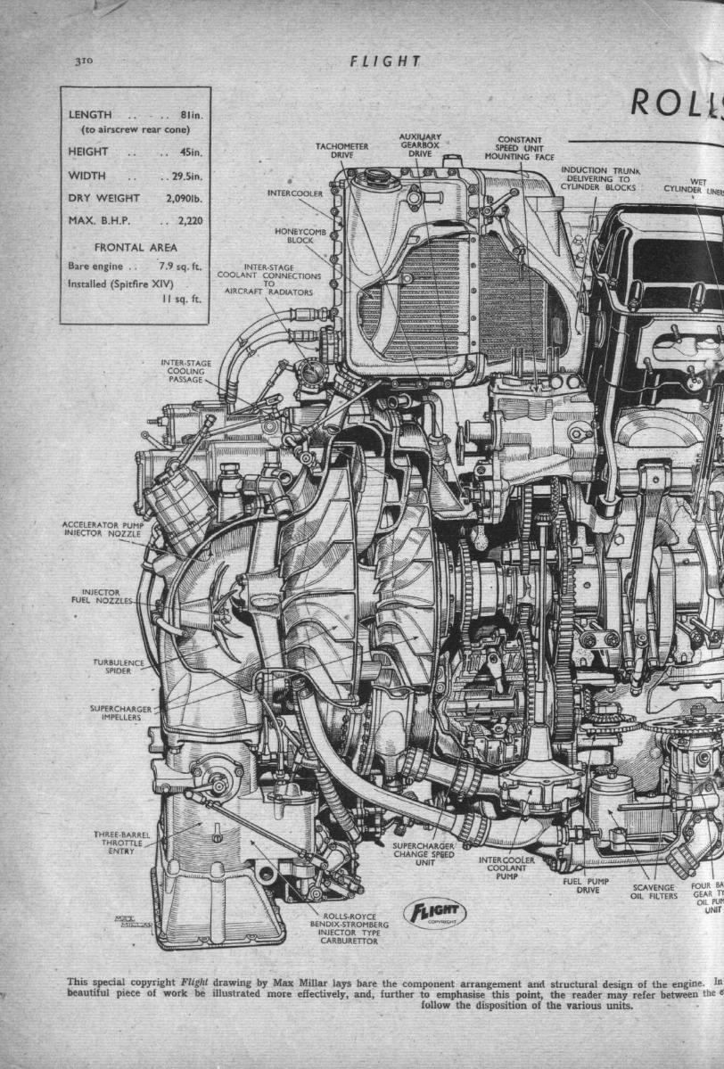
This special copyright Flight drawing by Max Millar iays bare the component arrangement and structural design of the engine, tobeautiful piece of work be illustrated more effectively, and, further to emphasise this point, the reader may refer between the &
follow the disposition of the various units.
SEPTEMBER 2OTH, 1945 311
QYCE GRIFFON (65) ENGINEWO EXHAUST T W O INLET
VALVES VALVESER CYLINDER PER C Y L I N D E R
V A L V ER O C K E R S
T W I N EXHAUST•CAMS
TWIN INLETCAMS
DRIVE TO CAMSHAFTFROM AIRSCREW
REDUCTION GEAR
TRANSVERSEBEARING CAP
BOLTS
STARTER DOGDRIVING CRANKSHAFTTHRO.UGH AIRSCREW
REDUCTION GEAR
CYLINDER HEADHOLDING D O W N
' STUD
FRONT SCAVENGEOIL DUCT
ANTI-SURGtOIL BAFFLE
CYLINDER BLOCKHOLDING D O W N
STUD
* MAINCOOLANT
PUMP
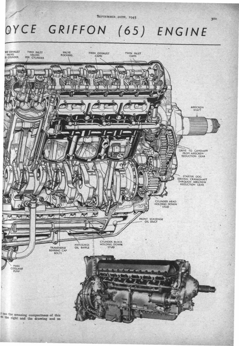
**t t h e amazing compactness of thisme right and the drawing and so
FLIGHT SEPTEMBER 2OTH, 1945
ROLLS-ROYCE GRIFFON (65)MAGNETO
the war the Griffon was rather displaced by theVulture until the latter was discarded, then theGriffon was resurrected as the need for a largerengine than the Merlin was again realised as anecessity. The various marks of Merlin Spitfireswere capable of handling enemy aircraft at height,but. when the Fw 190 was de-rated to give maxi-mum performance low down we were somewhatpressed. A quick decision was reached to put theGriffon II into some Spitfire VIII's, which then be-came the mark XII ; these were built in limitednumbers, but effectively squashed the opposition.
F.A.A. and R.A.F. Requirements
'] hese models of the Griffon wer,e all fitted withsingle-stage, two-speed blowers, and this basictype has progressed for Fleet Air Arm use (videthe Fairey Firefly), whilst the special needs of theR.A.F. have been met by the two-speed, two-
-stage engine for high-altitude use. As may beexpected, the Grifton owes a fair amount to Merlindevelopment, but what is peculiarly interesting isthat various practices initially proved on theGriffon have been incorporated in the laterMerlins.
Basically the engine is, of course,on the same lines as the Merlin,although the detail design is newpretty well throughout. One of themost important innovations is intaking the cam- and mag-drivesfrom the front. This was decidedupon in order to relieve the valveoperation from as much variationas possible: by interpolating asemi-floating coupling between thecrankshaft and the driving wheel ofthe reduction gearing and, in addi-tion, by taking the cam drives fromthe airscrew-driving gear, angularvariations in crankshaft speed aregreatly reduced in their transmis-sion to the camshafts. Further, air-screw inertia results in a reasonablyconstant rate of r.p.m., and, to top-off the advantages, the front driveallows a comparatively shorter
'overall length which, in turn, per-mits the larger and more powerfulengine to go into existing fighters
Whilst on the subject of the cank-shaft, we might as well deal withthat interesting component. It is,ol course, machined all over from aforged billet, and is fully counter-balanced, the front throw of No. 1,
ENGINE COOLANTOUTLETS TOHEADER TANK
MAGNETOINCLINED DRIVE
PORTCAMSHAFTDRIVE
AIRSCREWREDUCTION WHEEL
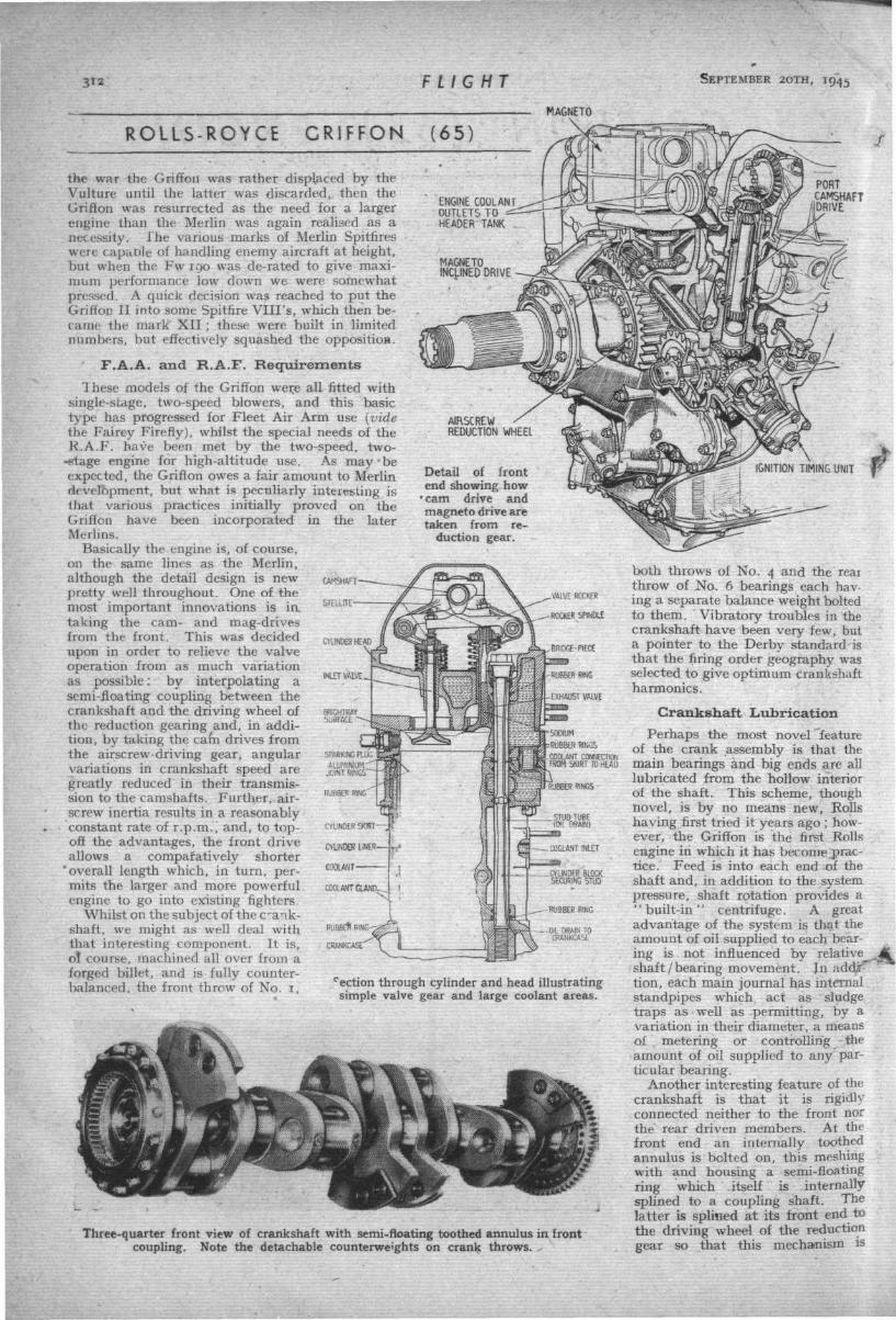
Detail of frontend showing how
• cam drive andmagneto drive aretaken from re-
duction gear.
CAMSHAFT-
STELLITE-
C8ANKCASE'
VAIVE ROCKER
ROCKtR SPINDLE
.BRIDGE-PIECE
I COOLANT CONNECTION1
I FROM SKIRT TO HtAO
.._ CYLINDER BLOCKSECURING STUD
--BUBBERRING
- 0 1 BRAIN TOCRANKCASE
cection through cylinder and head illustratingsimple valve gear and large coolant areas.
Three-quarter front view of crankshaft with semi-floating toothed annulus in frontcoupling. Note the detachable counterweights on crank throws.
both throws of No. 4 and the reaithrow of No. 6 bearings each hav-ing a separate balance weight boltedto them. Vibratory troubles in thecrankshaft have been very few, buta pointer to the Derby standard isthat the firing order geography wasselected to give optimum crankshaftharmonics.
Crankshaft LubricationPerhaps the most novel feature
of the crank assembly is that themain bearings and big ends are alllubricated from the hollow interiorof the shaft. This scheme, thoughnovel, is by no means new, Rollshaving first tried it years ago ; how-ever, the Griffon is the first Kollsengine in which it has become .prac-tice. Feed is into each end of theshaft and, in addition to the systempressure, shaft rotation provides a"bui l t - in" centrifuge. A greatadvantage of the system is that theamount of oil supplied to each bear-ing is not influenced by relativeshaft / bearing movement. Jn addjr"""tion, each main journal has internalstandpipes which act as sludgetraps as well as permitting, by avariation in their diameter, a meansof metering or controlling theamount of oil supplied to any par-ticular bearing.
Another interesting feature of thecrankshaft is that it is rigidlyconnected neither to the front northe rear driven members. At thefront end an internally toothedannulus is bolted on, this meshingwith and housing a semi-floatingring which itself is internallysplined to a coupling shaft. Thelatter is splined at its front end tothe driving wheel of the reductiongear so that this mechanism is

SEPTEMBER 2OTH, I 9 4 5 FLIGHT 1*3
ROLLS-ROYCE CRIFFON (65)
partly relieved from crankshaft rotational variations andtotally relieved from end-float effects.
Going to the other end of the shaft, we encounter thebeautifully neat torsional spring-drive coupling, the pur-pose of which is to relieve the crankshaft from impellerinertia. When the throttle is opened quickly the "fly-wheel ' ' inertia of the impellers does not allow them tobe accelerated as quickly as is the crankshaft by thepistons, and the resulting lag engenders a tendency to twistthe crankshaft. Again, when the throttle is rapidly closedthe impellers try to overrun the crankshaft, with reversedbut similar twisting effect. To relieve the shaft from theseembarrassments a spring drive is embodied between shaftand impellers, which absorbs the initial shock loading re-sulting from the inertia. The coaxial shaft and sleevewhich, splined together, form the springing member, areshown in a detail drawing.
There is not such a number of gears at the rear end ofthe Griffon as is found in the Merlin, the front-end cam-d r i v e arrangements,
^etc, being the cause;nevertheless, there isstill a goodly number ofwheels, bearings andshafts at the back ofthe Griffon, and to at-tempt to describe theseindividually would, aswell as being tedious,serve no worthwhilefunction. They canalmost all be traced inthe Max Millar drawingand other details ; how-ever, it is worthy ofemphasis that the nest-ing of this mass ofdrives is as compactand neat as the highestorder of mechanical de-sign ingenuity canmake it.
In the title sub-head-ing of this article arethe words ' ' ClassicOrthodoxy of Design,"and in the Griffon probably more than in any other Rollsengine is this trait manifest. There is nothing about theengine which is awfully cunning or ' ' super new." It isthe epitome pf plain, straightforward simplicity of design,
MAIN BEARINGOIL STAND PIPE
CRANKSHAFTBALANCE WIEGHT
STOP PLATELIMITING TORSIONALMOVEMENT SPRING DRIVE GEAR
Underside view of triple-entrythrottle with metering Venturis
and injector carburettor.
REDUCTION GEARP'NION COVER SEMI-FLOATING
DRIVE -ANULUSCRANKSHAFT OILPEED DE-AERATEh
CRANKSHAFT I AIR BLEED HOLErDA, • OIL SUPPLY TUBE ISUPPLY GIVING COUPLING .
DUCT
Three-quarter front view of semi-floating coupling betweencrankshaft and reduction gear.
Three-quarter rear detail of torsion spring drive coupling at.rear end of crankshaft.
fc* --' *s which is carried to the absolute of logical con-clusion. I t is for this reason, almost un-
i f w doubtedly, that the Griffon carries further the- " " s t a n d a r d set by,the Merlin as being the high-
est performance engine in exist-ence, for other engines of similarpower are larger or, if of thesame size, are lower powered.Such a feature, when coupled togreat reliability, cannot well beachieved by ' ' mushroommethods—it comes only by wayof lineage of thoroughbredsborn of painstaking care andunrivalled experience. I t is onthis foundation that the nameRolls-Royce rests so securely.
The main body of the Griffonis not unlike the later Merlinsin that it has a light-alloypentagonal-section crank-case,the lower half of which is a drysump housing the oil pressureand scavenge pumps with theirniters in a well at the rear end.
A baffle plate is also embodied in the lower half caseto restrict oil surge and prevent excessive breathing undernegative G accelerations. Cylinders are floating wet linersfitted in light alloy jacketing blocks, the compressive stressdue to the holding-down studs being taken by the jacket.The liners are chromium plated in the bores for about 2^inches down from the head as an anti-war measure, it beingin this area that maximum wear from corrosion and greattemperatures occurs. A flange is incorporated round thehead of the liner, and, with aluminium sealing rings aboveand below, is nipped between the cylinder head and jacket-ing block. Thus all thermal expansion and contraction ofthe liner takes place relative to the lower end.
This fashion of nipping the liners at the top means that,when tightened down, there is a gap of 0.15 in. betweenadjacent faces of the cylinder-head block and the jacketingblock which, until one knows the reason, looks very queer.To prevent excessive cantilever loading on the jointsadjacent to the end studs when at normal running tem-peratures, flat steel plates are interposed at each end ofthe cylinder bank between head and jacket, these platestransmitting the load as the engine warms up.
Combustion chambers are machined all over and arequite orthodox in shape. Valve seats are shrunk-in insertsand the porting passages are scurfed—very smoothly indeedon the inlet side (as is to be expected), but fairly roughlyon the exhaust side. The valves have Brightray seat fac-ings and, whilst the inlet valves have extended guides, the

FLIGHT SEPTEMBER 2OTH, 1945
ROLLS-ROYCE(CONT
exhaust valves are partially filled in the stems with metallicsodium.
Rocker gtar is very similar in design to that of theMerlin, the central camshaft operating the two rows ofvalves through cantilever rocker arms. The cams them-selves are of reasonably quick-lift profile and are designedto give harmonic negative acceleration. Two springs pervalve are employed, ofopposite helix and differingperiodicity, the latter beingan anti-surge measure.
The ignition system of theGriffon is well worthy ofattention, not so much as asystem, for the plugs and screening harness are standard,but in view of the unusual timing arrangement and very effi-cient magneto. This is a B.T.H. duplex type which runs "athalf engine speed, being driven through bevel gears from aninclined shaft taken from the base of the port bank camshaftdrive. The timing arrangement is " built-in " to the inclinedshaft arid comprises a hydraulic ram, at the base of theshaft, subject under control to engine oil pressure which isused to alter, as required, the linear position of the inclinedshaft. At the top end, the shaft is helically splined tothe mag.-driving bevel so that linear motion of the shaftwill, via the helical splines, cause a change in the relativepositions of the cam and rocker pad in the magneto toachieve the desired timing—i.e., the cam is caused to strikethe pad at an earlier or later point of crank angle. Addi-tionally, as the power input to change the timing is pro-vided by oil pressure, the pilot's control loading isextremely light; in fact the only load is that needed tooperate a smal! pilot valve to regulate oil flow to the ram.
Mention of pilot's controls leads one naturally to con-sideration of what, in the writer's opinion, is most aptlycalled the ' power lever control" system. Briefly, whatthis means is that, instead of the normal cockpit arrange-ment comprising separate throttle and airscrew or, rather,r.p.m. controls a single " p o w e r " lever is fitted whichgoverns the boost, r.p.m and ignition. Maximum perform-ance (that is, max. r.p.m. and max. boost) is obtained atfull forward movement of the single power lever, and atintermediate positions of the lever suitable combinationsof boost and r.p.m. are obtained for various other flightconditions.
Override Essential
There is little doubt that this scheme is a most usefulone in that it relieves the pilot from responsibility inensuring that the engine is always operating \mder thebest conditions.. However, it is rather essential that anoverride control be fitted to allow normal separate settingsof boost and r.p.m. when required—for example, whenlanding or in combat. The Griffon is provided with an over-ride lever for these particular functions, and there is everyreason to suppose that, despite the innate conservatism
of pilots, nothing but advantage can result from the useot the power lever control.
Further to ensure the most advantageous and saleoperation of the engine, a boost regulator unit is fittedthe purpose of which is to restrict boost pressure belowfull-throttle height to a safe maximum. As may berealised, although the maximum boost pressure of the
Griffon 65 is nominally 21lb. /sq. in., the blower iscapable of delivering nearlytwice this pressure at low alti-tudes, and in order that thepilot can slam forward the
GRIFFONINUED)
(65)
p elever to obtain maximum
power without having to worry about the safe boost limit,and to save the possibility of the engine from disintegra-tion with expensive noises, a regulator unit is installedwhich limits the delivery below throttle height for what-ever boost is being used in the appropriate gear. Theregulator comprises an aneroid-controlled relay piston linkedto the throttle butterflies by a differential gearing to shutoff the degree of throttle opening as necessary. The relavpiston is subject to the differentials of blower intake anddelivery pressures, so that if, for example, combat climbis required from the ground up, as eJtitude is gainedaneroid capsule tasting the boost will move a piston valveto admit the pressure difference across the blower to therelay piston to open the throttle progressively and main-tain boost up to full-throttle height.
Powers and Future Use
Whilst on the question of powers it is noteworthy thatthe continuous cruising powers of the Griffon 65 are wellover i.ooo h.p. from sea level up to over 30,000ft. Com-pare this with the original Merlin at the outbreak of warwhich had a maximum S.L. power of 880 h.p. (at 6J lb.boost) rising to 990 at 12,250ft., the maximum ratedheight.
Although the Merlin is ^uch a magnificent engine—theoutstanding engine of all time—as an alternative for futureair liners, it would surely be sensible to instal a deratedGriffon to give similar performance more economically and,at the same time, gain all the benefits of advanced de-velopment. I t is not without significance that the Griffonis one of the very, very few engines ever to have succeededto general service without experiencing modifications neces-sitating grounding. There is, too, a good deal of advan-tage the Griffon has over the Merlin on the subject ofservicing and maintenance.
We have mentioned that the maximum boost of theGriffon 65 is 21 lb./sq. in., but there are other models inexistence which have been passed for 25 lb./sq. in. maxi-mum boost (with 100/1,50'grade fuel) and the maximumpowers in the respective moderate and full superchargegears have thus been stepped up to : MS, 2,375 b.h.p. at1,250ft., and FS, 2,140 b.h.p. at 15,500ft.
HIGH PRESSUREOIL FROM ENGINE
DRIVEN PUMP
COMPRESSED AIRFROM AUTOMATIC
ANEROID GOVERNOR
r
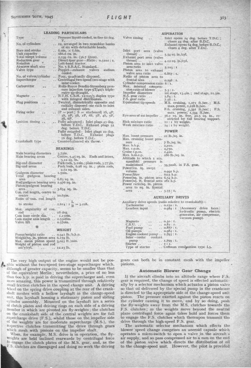
Diagrammatic illustration of supercharger change-speed unit showing (left) MS gear engaged ; (centre) changing from MS to FSgear ; and (right) FS gear engaged.
SEPTEMBER *2OTH, 1945 FLIGHT 3*5
LEADING PARTICULARSType . . . . . . Pressure liquid-cooled, in-line Go deg.
No. of cylinders . . 12, arranged in two monobloc banksof six with detachable heads.
.. Coin, x 6.6in.
.. 186.6 cu. in.
. . 2,239 cu- m - (36-7 litres).,. Direct spur gear—:Ratio : 0.5102 : 1.. . Left-hand tractor.... No. 5 S.B.A.C. Standard., . Poppet—exhaust valves sodium
cooled... Four, quadrantly disposed... Centrifugal two-speed two-stage with
inter-cooler.. . Rolls-Royce Bendix-Stromberg pres-
sure injection type 9T/40/1 triple-entry up-draught.
.. B.T.H. C.S.H. 12-125/3 duplex typewith integral distributors.
,. Two/cyl. diametrically opposite andradially disposed one each to inletand exhaust sides.
,. (P = port; S = starboard) iS, 4P,3S, 2P, 5S, iP, 6S, 3P, 4S, 5P,2S, 6P.
,. Fully advanced : Inlet plugs 45 deg.before T.D.C. Exhaust plugs 51deg. before T.D.C.
Fully retarded : Inlet plugs 10 deg.before T.D.C. Exhaust plugs16 deg. before T.D.C.
. Counterbalanced six throw. •
Bore and strokeUnit capacityTotal swept volumeReduction gearRotation . . * .Airscrew shaft sizeValve, type
No. of valves/cylinderSupercharger
Carburettor
Magneto
Plug positions
Firing order . .
Ignition timing . .
Crankshaft type
BEARINGSMain bearing diametersMain bearing areas
Big-end diameterBig-end areas
Centre, 5.45 sq. in. Ends and inters,5.12 sq. in.
Fqrk rods, 3.10m.; plain rods, 3.773m.Fork rods, 6.28 sq. in. ; plain rods,
2.61 sq. in.1.50m.Gudgeon diameter
Total gudgeon bearingarea . . . . . . 6.83 sq. in.
Rod/gudgeon bearing area 2.976 sq. in.Piston/gudgeon bearing
area . . . . . . 3.854 sq. in.Con. rod length, centre to
centre . . ' . . 10.65m.Ratio of con. rod length
to stroke .. . . 1.614 : i ^ = 3.228.Max. angularit)' of con.
rodCam base circle dia.Cam major axis length . .Valve lift . . . .
18 deg.1.150m.
I.53o8in.0.570m.
WEIGHTPower/weight ratio . . 0.941 Ib./b.h.p.Weight/sq. in. piston area 6.159 lb-Max. mean piston speed 3,025 ft./min.Weight of piston and rod
ass'y/cyl. " . . . . 12.23 lb.
Valve timing
Inlet portthroat)
area (valve
ASPIRATION. . Inlet opens 24 deg. before T.D.C.;
closes 44 deg. after B.D.C.Exhaust opens 64 deg. before C.D.C.;
closes 4 deg. after T.D.C.
Exhaust port area (valve5-54 sq. in./cyl.
throat) . . 4.12 sq. in./cyl.Piston area to inlet valve
area ratio . . 5.103 : 1Piston area to exhaust
valve area ratio . . 6.867 : !•Ratio of piston area to
frontal area . . . . 0.298 : 1.Cylinder compression ratio 6 : 1 .Max. internal compres-
sion ratio of blowerImpeller diametersM.S. gear ratio . .F.S. gear ratioEquivalent tip speeds
Eye area of 1st impeller
Rich mixture ratioWeak mixture ratio
5-3:1-1st stage, 13.4m. ; 2nd stage, 11.3m5.84 : 1.7-5S: 1.M.S. cruising, 1,071 ft./sec.; M.S
max. power, 1,228 ft./sec.F.S. cruising, 1,391 ft./sec:;
max. power, 1,594 ft./sec.56.1 sq. in. free, 40.5 sq. in.,
stricted by tail bearing support.11 : 1 by weight.14 : 1 by weight.
POWER21 Ib./sq. in.
F.S.
re-
Max, boost pressureMax. cruising boost pres-
sureMax. b.h.p.Max. r.p.m.Cruise r.p.m.Max. b.m.e.p.Altitude to which 1 ata.
manifold pressure ismaintained
Power/cu. in. sweptvolume
Power/litre . . „„.., . . . r.Power/sq. in. piston area 6.54 h.p.Power/sq. ft. frontal area 281 h.p.Power ratio/sq. in. piston
area to sq. in. frontal' area . . . . ' . . 3.35 : 1.
AUXILIARY DRIVESAuxiliary drive speeds (ratio relative to crankshaft)—
Tachometer . . . . 0.250 : 1.Gearbox input . . 0.984 : 1
7 lb./sq. in.2,220.2,750-2,400.286 lb./sq. in.
39,500ft. in F.S. gear.
0.992 h.p.60.5 h.p.
MagnetoC.S.UFuel pumpOil pumpsEngine coolant pump . .Inter - cooler coolant
pumpStarterType of starter
0.50: 1.0.82 : 1.0.887 : 1.0.984 : 1.1-793 : i-
1.799 : i-1 : 1 .
Coffman
(Accessory drive faces:hydraulic pump, electricgenerator, air compressor,vacuum pump).
Coffman combustion type L5.
-V The very high output of the engine would not be pos-^» sible without the two-speed two-stage supercharger which,
ait.hough of greater capacity, seems to be smaller than thatof the equivalent Merlin; nevertheless, a price of no lessthan 600 h.p. is paid in driving the supercharger and, evenmore amazing, this power is transmitted through relativelysmall friction clutches in the speed change unit. A drivingfrheel on the spring drive coupling at the rear of the crank-shaft meshes with a hollow layshaft in the change-speedunit, this layshaft housing a stationary piston and sliding
'•:• cylinder assembly. Mounted on the layshaft are a seriesof clutch plates and driving rings on each side of a driving
I member in which are pivoted six fly-weights ; the clutcheson the crankshaft side of the central weights are for fullsupercharge drive (F.S.), whilst those on the impeller side<>! the weights are for moderate supercharge (M.S.), therespective clutches transmitting the drive through gearswhich mesh with pinions on the impeller shaft.
When, for example, M.S. drive is in operation, the fly-Weights are held inclined rearwards by centrifugal force
k t>; engage the clutch plates of the M.S. gear, and, as thei 'S. clutches are disengaged and doing no work th,e driving
gears can both be in constant mesh with the impellerpinions.
Automatic Blower Gear ChangeIf the aircraft climbs into an altitude range where F.S.
gear is required, the change of speed is effected automatic-ally by a selector mechanism which actuates a piston valveso that oil delivered by the special pump in the crankcaseis directed to the appropriate side of the change-speed unitpiston. The pressure exerted against the piston reacts onthe cylinder causing it to move, and by so doing, pushthe fly-weights away from the M.S. clutches towards theF.S. clutches; as the weights move beyond the neutralplane centrifugal force again takes hold and forces themto engage the F.S. clutches which thereupon transmit thedrive through the high-speed F.S. gear.
The automatic selector mechanism which effects theblower speed change comprises an aneroid capsule whichoperates a micro-switch to open a valve in the aircraft'sair supply, and so pass compressed air to a ram on the endof the piston valve which directs the distribution of oilto the change-speed unit. However, the pilot is provided

FLIGHT SEPTEMBER 2OTH, 1945
ROLLS-ROYCE GRIFFON (65)
with a change-speed switch to by-pass the aneroid andthus permit a change in blower speed for emergency use,to allow of retaining low gear for formation flying, or toallow of ground testing.
In order that no ill effects result from small axialmovement as between the driving gears of the speed-change unit and also to preclude the effects of an over-hung drive, the respective drive pinions on the impellershaft are not integral. In point of fact, only the M.S.pinion is mounted on the impeller shaft itself, the F.S.pinion being supported in a housing around the spring-drive sleeve, with a bell coupling separating the pinionsand splined to each.
Induction is updraught through a triple-barrel- throttlein the mouths of which are the Venturis for fuel meteringbalance. The carburettor is a Rolls-Royce modification ofthe Bendix-Stromberg metering injector, and supplies agoverned measure of fuel to a series of discharge nozzlesarranged in a " h u b " from which project eight "spokes."On the downstream side of these is created a depressionor turbulent area into which the fuel nozzles discharge,and from here the mixture is taken straight into the eyeof the first-stage impeller. Rectifying and diffuser vanesare interposed between the first and second impellers, andin this inter-stage area the blower casing is cooled by itsown little coolant system. From the second-stage impellerthe charge is passed through a further diffuser ring and
Sir Arthur TedderVDeputy Supreme Commander
THE London Gazette of Septembern t h announced the promotion
of Air Chief Marshal Sir ArthurTedder, G.C.B., to Marshal of theRoyal Air Force.
The public remembers Sir Arthurchiefly as having been A.O.C.-iu-C.the Mediterranean Air Command from1943 until he was appointed DeputySupreme Commander of the AlliedArmies of Liberation under GeneralEisenhower. But his earlier careerhad been full of promise. He enteredthe Army in 1913 with a Universitycommission from Cambridge, wherehe was at Magdalene College. As anundergraduate he gained a University
so to the volute delivering to the intercooler. An accelera-tor pump is located in the up-draught throat between thenozzle spider and the impeller eye, and discharges througha single nozzle.
The inter-s'tage impeller case cooling has the effect ofincreasing the charge density as an irTtermediate measure,and by so doing increases the capacity efficiency of thesecond stage. This principle lies behind the use of themain intercooler, for an increase in charge density for agiven volume enhances the volumetric efficiency, andalthough this leads to a large flow through the carburettorand, thus, a higher consumption, relative to the powerincrease, the step-up in consumption is well worth while.
For the future, Rolls-Royce have evolved a meteringpump to supplant the present system, and it also seemslikely that water / methanol injection will be introducedbefore very long, not necessarily only as an emergencymeasure but as a normal running condition. Direct in-jection to individual cylinders will also, without doubt,eventually be incorporated. There is this to be said for thenew metering pump : it is an extraordinarily simple unitof great reliability and meters so accurately throughoutthe whole performance range that it is not too much ofan exaggeration to state ,,that flights could be planned towithin a half-gallon of fr^ll endurance. With this is natur-ally Jjj3lwfr"1T*TOn*«4«nd pre-knowledge of specific con-
ption such as hjpsn^yer before been known.
'omotioiiof the Royal Air ForceM&rsl
JOL
Marshal of trie R.A.F.Sir Arthur Tedder,
G.C.B.
^ Aon the^Navy of the Restoration, which was
iewed in/^he Times. His first commission wasRegiment, and with it he went to France in
__ us he be,l<5ngs to the honourable company of " Old:mptibles.",.~'ln 1916 he was seconded to the Royal Flying
Corp?, and during the war was mentioned several times indespatches. >4ut the battle of Arras in 1917 he commanded No.70 Squadron, which was equipped with 18 Sopwith two-seaters.•—. Since the 1918 Armistice Tedder saw service during theChanak crisis in 1922. In 1928 he attended a course at theImperial Defence College—a very good preliminary for hissubsequent post as Deputy Supreme Comma^fler of British andAmerican forces of all Services. In 1936 he was appointedA.O.C. Far East Command, with headquarters at Singapore.He has also held various important posts at the Air Ministry,including that of Director-General of Research and Develop-ment and'Director of Training.
LINCOLN'S CIVIL SISTER : A new photograph of the Avro Tudor I doing a little overweather flying. The wing arrange-ment of the Lincoln and the Tudor I is identical.