Embed Size (px)
Citation preview
Roll Controlfor aMicro Air VehicleUsingActiveWing Morphing
HelenGarcia�, MujahidAbdulrahim
�and Rick Lind
�University of Florida
1 Introduction
Relatively small aircraft have recently beenreceiving considerable attention in the flight testcommunity. Inparticular, aircraft denoted by DARPA asa micro air vehicle, MAV, arebeing designedwith wing spanlessthan6 in to operateat airspeedslessthan25 mph. Suchaircraft areenvisioned asexpendableplatforms forsurveillance anddatacollection thatcanoperatein dangerousor confinedspaces.
TheUniversity of Florida hasbeenextremely active in thefield of MAV design andtesting. The teamled byDr. PeterIfju is especially accomplishedin that they have won various aspects of the Micro Aerial VehicleCompetition, sponsoredby the International Society of Structural and Multidi sciplinary Optimization, eachyearfrom 1999to 2002.His teamhasdesigned,built, andflown many unique designs ranging from 2 ft to 4 inwing spanthatareremotelypiloted usingvision feedbackto a ground station.
Most of the MAVs currently beingflown at the University of Florida have a similarity; namely, theseaircraftaredemonstrably difficult to fly. Suchdifficulty is somewhat expectedgiven that the aircraft arehighly agileandmaneuverablebut mustbeflown remotely. Theteamis currently investigatingmethodsof activecontrol fortheMAV that would allow autonomousoperation andgreatly extend the applications for which suchvehiclesmaybeconsidered.
The useof innovative control effectors is an areabeing explored asan enabling technology for designing astability augmentationsystem.Thecurrent generationof MAV usestraditional effectors,specifically anelevatorandrudder, whosepositionsarecommandedby theremote pilot. Theelevatorpresentsadequateeffectivenessfor longitudinal control but the rudder presents somedifficulty for lateral-directional control. Basically, therudder mainly excites the dutch roll modeso steering and gust rejection are really accomplished using thecoupled roll andyaw motion resulting from dutch roll dynamics. Suchan approachis obviously not optimalbut traditional aileronsarenot feasible on this typeof aircraft.
Theconcept of morphing presentsseveral opportunitiesfor enabling control of aMAV. Morphing is particularlyappealing for twisting thewing andenabling roll control. Wing twist is actually usedon thecurrentMAV butin apassivesense. Essentially, thewing deformsunder loading in flight to produceapassivewashout thathelpssmooththeflight path. Sucha conceptcanbeextendedto allow greatertwists that areactively commanded togeneratelargeroll moments.�
GraduateStudent�UndergraduateStudent�AssistantProfessor, Departmentof Mechanicaland AerospaceEngineering,231 Aerospace Building, GainesvilleFL, 32611,
[email protected], SeniorMemberAIAA (Corresponding Author)
1
This� paperconsidersusing morphing for roll control of a MAV designedby Dr. Ifju’ s teamat the Universityof Florida. This vehiclehasa 10 in wing spanwith membranewings that arehighly flexible. Theopen-loopresponsesof the aircraft are investigatedusingthe rudder andactive wing twisting. The resulting flight datais usedto generatemodelsthat describe the flight dynamics.A simplestability augmentation systems is thendesignedthatallows theaircraft to accuratelytrackroll commandswithout incurring excessiveyaw or sideslip.
The continuing maturation of materials andcontrols technology is leading to consideration of morphing onlarger scales for envisioned aircraft projects.Sucha concept is being adoptedfor theActive AeroelasticWingto provideroll control of anF/A-18[6]. Activemorphing is areasonableconceptfor full-sizeaircraft; however,thepowerandsizerequirementsfor morphing actuators,suchasactivematerials, precludestheir useonaMAV.Therefore, themorphing in this study is accomplishedby directly connecting a servo,fixed in thefuselage,topoints nearthe trailing-edge outboardof eachwing. The resulting wing twist is shown to act similarly toaileronsfor generating rolling moments.
2 Micro Air Vehicle
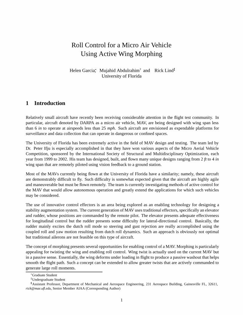
This paper will utili zethemicro air vehicle (MAV) shownin Figure1.
Figure1: Overhead View of theMAV
Thebasic propertiesof theMAV aregivenin Table1.
Property ValueWingspan 10”Wing Area 29 ���
Wing Loading 14 �� ������ Aspect Ratio 3.44Powerplant Electric motorw/ 2.25” propeller
Total Weight 80g
Table1: Propertiesof theMAV
2
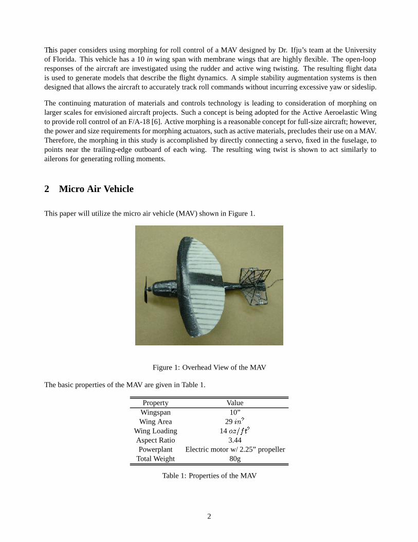
The� flight testvehicle is basedon a family of flexible-wing micro air vehicles designed by the University ofFlorida. Theairframeis constructed entirely of compositecarbon-fiber. Thefuselageis atwo-piecemonocoquestructuredesignedto houseflight components,control effectors, andinstrumentation. A conventional empen-nageis affixed to the fuselagewith elevator andrudder control surfaceshinged to the horizontal andverticalstabilizersrespectively asshown in Figure2.
Figure2: Empennageof theMAV
Thewing, which is mounted on cabin struts 0.75” above the fuselage,is constructedusingsimilar compositetechniquesasthe fuselageandempennage.The leading edgeconsists of a single layer of carbon-fiber weavewith battensof unidirectionalcarbon attachedto theundersideandextending to thetrailingedge. Thecompositewing skeleton is covered with an extensible membraneskin of latex rubber. The resulting structure canbegrossly deformedvia mechanical actuation yet is capable of withstanding flight loads. The flexible nature ofthewing alsogivesrise to themechanismof adaptive washout which permits small changesin wing shape inresponseto gusty wind conditions.
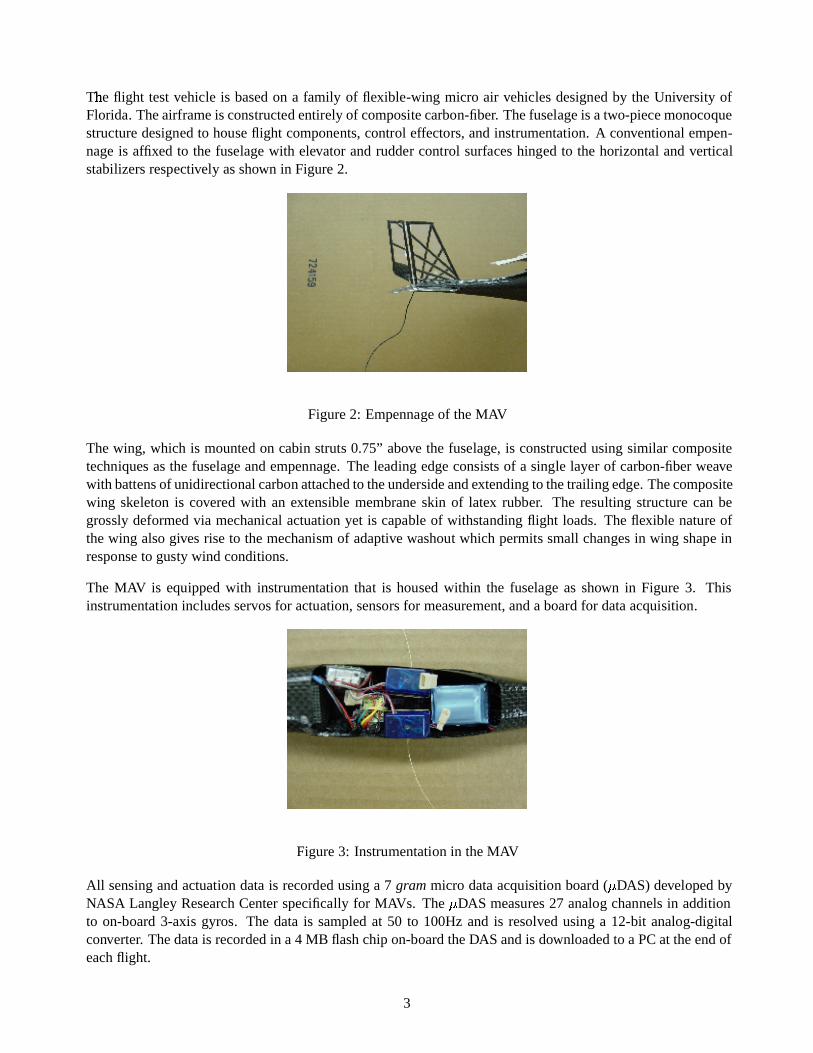
The MAV is equipped with instrumentation that is housedwithin the fuselage as shown in Figure 3. Thisinstrumentation includesservosfor actuation,sensors for measurement,anda board for dataacquisition.
Figure3: Instrumentation in theMAV
All sensing andactuation datais recordedusing a 7 grammicro dataacquisition board ( � DAS) developedbyNASA Langley Research Centerspecifically for MAVs. The � DAS measures27 analog channelsin additionto on-board3-axis gyros. The datais sampledat 50 to 100Hzand is resolved using a 12-bit analog-digitalconverter. Thedatais recordedin a 4 MB flashchip on-boardtheDAS andis downloadedto a PCat theendofeachflight.
3
The� currentstudyconsidersonly therolli ng responseof thevehicle. Correspondingly, theinitial flights recordonly roll rateusing a Tokin 3AOB ceramic angular ratesensor. This sensor hasa resolution of approximately0.4547 mV/deg/swith a maximumoutput of 5 V.
Actuation of the MAV is accomplished with threecontrol effectors or servos mounted inside the fuselage.Thesedevices actuate the control surfacesor wing morphing by rotating an arm and pushing or pulling apushrod. Thecontrol surfacesof elevator andrudder areconnectedto the servousing a spring steelpushrod.Thewing morphing is achievedby connecting theservo to thewing edgeusing a thin strandof Kevlar threads.Theapproximaterange of motion for each is givenin Table2.
Effector Rangeof Motionelevator ������� to �������rudder ��� � � to ��� � �
morphing �!����� to � �Table2: Rangeof ControlEffectors
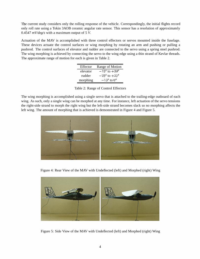
Thewing morphing is accomplishedusing a single servothat is attachedto thetrailing-edge outboardof eachwing. As such,only asinglewing canbemorphedatany time. For instance,left actuation of theservotensionstheright-side strand to morphtheright wing but the left-sidestrand becomesslacksono morphing affectstheleft wing. Theamountof morphing that is achievedis demonstratedin Figure4 andFigure5.
Figure4: RearView of theMAV with Undeflected(left) andMorphed (right) Wing
Figure5: SideView of theMAV with Undeflected(left) andMorphed (right) Wing
4
3 Open-Loop Flight Tests
A seriesof flight testsareperformedwith theMAV for thisproject. Thesetestsprovideanimmediateindicationof the flight propertiesassociatedwith the wing morphing. The testing alsoallows preliminary indicationofthedifficulty in piloting theMAV usingthemorphing ascomparedto therudder. Finally, thetesting generatesdatafrom which modelsandcontrollersarederived.
Flight testing of theactive wing-shapingMAV is performedin theopen areaof a radiocontrolled (R/C) modelfield during which windsconditionsrangefrom calmto 7 knotsthroughout theflights. Oncetheflight controlandinstrumentation systemsarepoweredandinitialized, theMAV is hand-launchedinto thewind. This launchis aneffectivemethodto quickly andreliably allow theMAV to reachflying speedandbegin aclimb to altitude.The airplane is controlled by a pilot on the ground who maneuversthe airplanevisually by operating an R/Ctransmitter. Thedataacquisition system begins recording assoon asthemotor is powered.
Theaircraft design allowseither rudder or wing shaping to beusedastheprimary lateral control for standardmaneuvering. Theairplaneis controlled in this mannerthrough turns, climbs,andlevel flight until a suitablealtitude is reached. At altitude, the airplane is trimmedfor straight and level flight. This trim establishesaneutral referencepoint for all thecontrol surfacesandfacilitatesperforming flight testmaneuvers.
The flight test maneuver of interest is a control doublet for both rudder and wing shaping controls. Thismaneuveris performedby commandingaconstantleft deflection for acertain timeperiod foll owedimmediatelyby a right deflection for the sametime period andfinally returning to the neutral position. Aircraft responsecharacteristics to thecontrol input arethendeterminedby analysisof theservoposition androll rate.
Therudder doubletsexhibit a coupledroll-yaw response.On first actuation of therudder, theaircraft typicallyrolls to a "#��� bankangleandyaws approximately ���$� . The onset of opposite control input rolls the airplanequickly in the opposite direction with an additional yawing andpitching tendency. After the maneuver, theMAV is in a banked dive with several feet of altitude lost throughout the course of the doublet. As expected,therudder appears to excite thedutchroll moderesulting in coupledroll andyaw response.
Wing-shaping control doubletsinduce a different behaviorof the MAV. The responseof the airplaneto wingshaping is similar in nature to responses from ailerons. Essentially, the aircraft responseto the morphingis predominantly roll motion with little yaw or pitch coupling. Thus, the doublets are performed withoutconsiderable directional or altitude deviation. Following the completion of the maneuver, which resemblesrocking thewings,theairplaneis in abankedattitude. Recovery from thewing shaping doublet is considerablyeasier thanthat of therudder doublet. Sucha responseindicatesthewing shaping excites theroll convergencemode.
Clearly, theMAV requiresastability augmentation systemto facilitateoperationandgreatly expand its missioncapability. In general, lateral maneuvers areparticularly difficult becausethe MAV is so responsive. Smalllevels of actuation caneasily achieve roll rateabove 200 deg/s for thesehighly maneuverablevehicles. Theintroduction of a controller would lessen pilot workload for trajectory tracking andenabledevelopmentof avision-basedautopilot systemcurrently being designed[1].
The open-loop flight tests demonstrate the value of morphing for consideration of a stability augmentationsystem. Theruddercanbeusedto generatelateral maneuversbut thetight coupling of roll andyaw complicatesthecontrol needed for trajectory tracking. Conversely, themorphingproducesalmostpureroll soanassociatedcontroller for tracking roll commandscould berelatively simple.
5
4 Modeling
4.1 Parameter Estimation
A modelof theflight dynamics of theMAV is used to design thestability augmentation system.Thesemodelsarenecessarily developedby analysis of flight databecauseof theoretical difficulties. For instance,computa-tional predictionsof theaerodynamicsaresuspectfor thelow ReynoldsnumbersatwhichtheMAV operates[5].Also, theaeroservoelastic responseof a membranewing is challenging to predict. Themodelis therefore de-pendenton measurementstaken during flight.
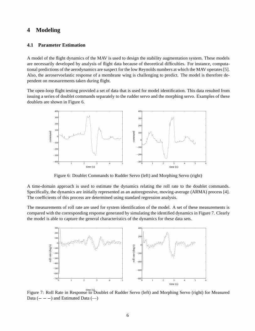
Theopen-loop flight testing provideda setof datathat is usedfor modelidentification. This dataresulted fromissuingaseriesof doubletcommandsseparatelyto therudderservo andthemorphing servo. Examplesof thesedoubletsareshown in Figure6.
0 1 2 3 4 5−400
−300
−200
−100
0
100
200
300
400
time (s)
com
man
d
0 1 2 3 4 5 6−300
−200
−100
0
100
200
300
400
time (s)
com
man
d
Figure6: DoubletCommandsto RudderServo (left) andMorphing Servo (right)
A time-domain approach is used to estimate the dynamics relating the roll rate to the doublet commands.Specifically, thedynamicsareinitially representedasanautoregressive,moving-average(ARMA) process[4].Thecoefficientsof this processaredeterminedusing standardregressionanalysis.
Themeasurementsof roll rateareusedfor systemidentification of themodel. A setof thesemeasurementsiscomparedwith thecorrespondingresponsegeneratedby simulatingtheidentified dynamicsin Figure7. Clearlythemodelis ableto capture thegeneral characteristicsof thedynamicsfor these datasets.
0 1 2 3 4 5−700
−600
−500
−400
−300
−200
−100
0
100
200
300
time (s)
roll
rate
(de
g/s)
0 1 2 3 4 5 6−800
−600
−400
−200
0
200
400
time (s)
roll
rate
(de
g/s)
Figure7: Roll Ratein Response to Doublet of RudderServo (left) andMorphing Servo (right) for MeasuredData( �%�&� ) andEstimatedData(—)
6
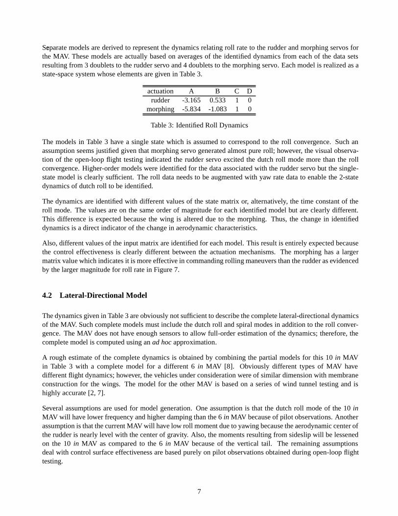
Separat' e modelsarederived to representthedynamics relating roll rateto therudder andmorphing servos forthe MAV. Thesemodelsareactually basedon averagesof the identified dynamics from each of the datasetsresulting from 3 doubletsto therudder servo and4 doubletsto themorphing servo. Eachmodelis realizedasastate-spacesystemwhoseelements aregivenin Table3.
actuation A B C Drudder -3.165 0.533 1 0
morphing -5.834 -1.083 1 0
Table3: Identified Roll Dynamics
The modelsin Table3 have a single state which is assumedto correspondto the roll convergence. Suchanassumptionseemsjustifiedgiventhatmorphing servogeneratedalmostpureroll; however, thevisual observa-tion of the open-loop flight testing indicated the rudder servoexcited the dutchroll modemorethanthe rollconvergence.Higher-ordermodels wereidentified for thedata associatedwith therudder servo but thesingle-statemodelis clearly sufficient. Theroll dataneeds to beaugmentedwith yaw ratedatato enable the 2-statedynamicsof dutchroll to beidentified.
Thedynamicsareidentified with differentvaluesof the statematrix or, alternatively, the time constant of theroll mode. The valuesareon the sameorderof magnitude for each identified modelbut areclearly different.This differenceis expectedbecausethe wing is altered due to the morphing. Thus, the change in identifieddynamicsis a direct indicatorof thechange in aerodynamiccharacteristics.
Also, different valuesof theinput matrix areidentified for eachmodel.This result is entirely expectedbecausethe control effectiveness is clearly different between the actuation mechanisms. The morphing hasa largermatrixvaluewhichindicatesit is moreeffectivein commandingrolling maneuversthantherudder asevidencedby thelarger magnitudefor roll ratein Figure7.
4.2 Lateral-Directional Model
Thedynamicsgivenin Table3 areobviouslynotsufficient to describethecompletelateral-directionaldynamicsof theMAV. Suchcomplete modelsmustincludethedutchroll andspiral modesin addition to theroll conver-gence. TheMAV doesnot have enough sensors to allow full -orderestimation of the dynamics; therefore, thecomplete modelis computedusinganad hocapproximation.
A rough estimateof the complete dynamics is obtained by combining the partial modelsfor this 10 in MAVin Table 3 with a complete model for a different 6 in MAV [8]. Obviously different types of MAV havedifferentflight dynamics;however, thevehiclesunderconsideration wereof similar dimension with membraneconstruction for the wings. The model for the other MAV is based on a series of wind tunnel testing and ishighly accurate[2, 7].
Several assumptions areusedfor modelgeneration. Oneassumption is that the dutchroll modeof the 10 inMAV will have lower frequency andhigherdamping thanthe6 in MAV becauseof pilot observations.Anotherassumptionis thatthecurrentMAV will havelow roll momentdueto yawing becausetheaerodynamiccenteroftherudder is nearly level with thecenter of gravity. Also, themomentsresulting from sideslip will belessenedon the 10 in MAV as compared to the 6 in MAV becauseof the vertical tail. The remaining assumptionsdealwith control surfaceeffectivenessarebasedpurely on pilot observations obtainedduring open-loop flighttesting.
7
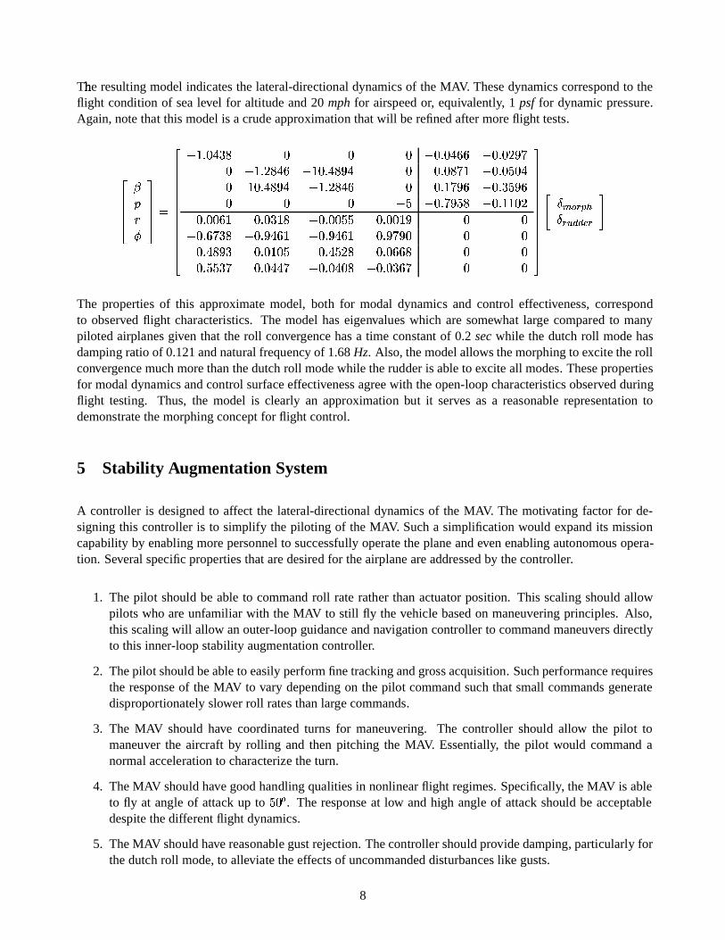
The� resulting modelindicatesthe lateral-directional dynamics of theMAV. Thesedynamics correspondto theflight condition of sealevel for altitudeand20 mph for airspeedor, equivalently, 1 psf for dynamicpressure.Again,notethat this modelis a crude approximation thatwill berefinedaftermoreflight tests.
()))* +, -./1000243
())))))))))))*����56��"#7 8 � � � �9�:56��"#; ; �9�:56�<� =<>� ����51� 8?"#; ���@�:5A"#8 =?" � �:56�<8<>B� �9�:56�<����"� �@�:5A"#8 =?" �!��51� 8?"#; � �:5C��>�= ; �9�:517 � = ;� � � ��� �9�:5D>�= � 8 �9�:5C� �@�<��:56� �<;:� �:56�<7:��8 ���:56� �<� � �:56� �E��= � ��9�:51;<>�7 8 �9�:51=?"#;:� ���:51=?"#;:� �:51=<>�=�� � ��:5A"#8 = 7 �:56�E�@�<� �:5A"#� � 8 �:56�<; ; 8 � ��:51� � 7<> �:56��" "�> ���:56��"<�<8 �9�:56�<7 ;<> � �
/ 0000000000002FHGJI �LKNM�OG KQP�RSRUTVKXW
The properties of this approximate model, both for modal dynamics and control effectiveness, correspondto observed flight characteristics. The modelhaseigenvalueswhich aresomewhat large compared to manypiloted airplanesgiven that the roll convergencehasa time constantof 0.2 secwhile the dutchroll modehasdamping ratioof 0.121andnatural frequency of 1.68Hz. Also, themodelallowsthemorphing to excite therollconvergencemuchmorethanthedutchroll modewhile therudderis ableto excite all modes. Thesepropertiesfor modaldynamicsandcontrol surfaceeffectivenessagreewith theopen-loop characteristics observedduringflight testing. Thus, the model is clearly an approximation but it serves as a reasonable representation todemonstratethemorphing conceptfor flight control.
5 Stability Augmentation System
A controller is designedto affect the lateral-directional dynamics of the MAV. The motivating factor for de-signing this controller is to simplify the piloting of the MAV. Sucha simplification would expandits missioncapability by enabling morepersonnel to successfully operate theplaneandevenenabling autonomousopera-tion. Severalspecific propertiesthataredesired for theairplaneareaddressedby thecontroller.
1. The pilot should be ableto commandroll raterather thanactuator position. This scaling should allowpilots who areunfamiliar with the MAV to still fly the vehicle basedon maneuvering principles. Also,this scaling will allow anouter-loopguidanceandnavigationcontroller to commandmaneuversdirectlyto this inner-loopstability augmentation controller.
2. Thepilot should beableto easilyperformfinetrackingandgrossacquisition. Suchperformancerequiresthe responseof the MAV to vary depending on the pilot command such that small commandsgeneratedisproportionately slower roll rates thanlarge commands.
3. The MAV should have coordinated turns for maneuvering. The controller should allow the pilot tomaneuver the aircraft by rolli ng and then pitching the MAV. Essentially, the pilot would commandanormal accelerationto characterize theturn.
4. TheMAV should have goodhandling qualities in nonlinearflight regimes.Specifically, theMAV is ableto fly at angle of attack up to ��� � . The responseat low andhigh angle of attack should be acceptabledespite thedifferentflight dynamics.
5. TheMAV should havereasonablegustrejection. Thecontroller should providedamping, particularly forthedutch roll mode,to alleviate theeffects of uncommandeddisturbanceslike gusts.
8
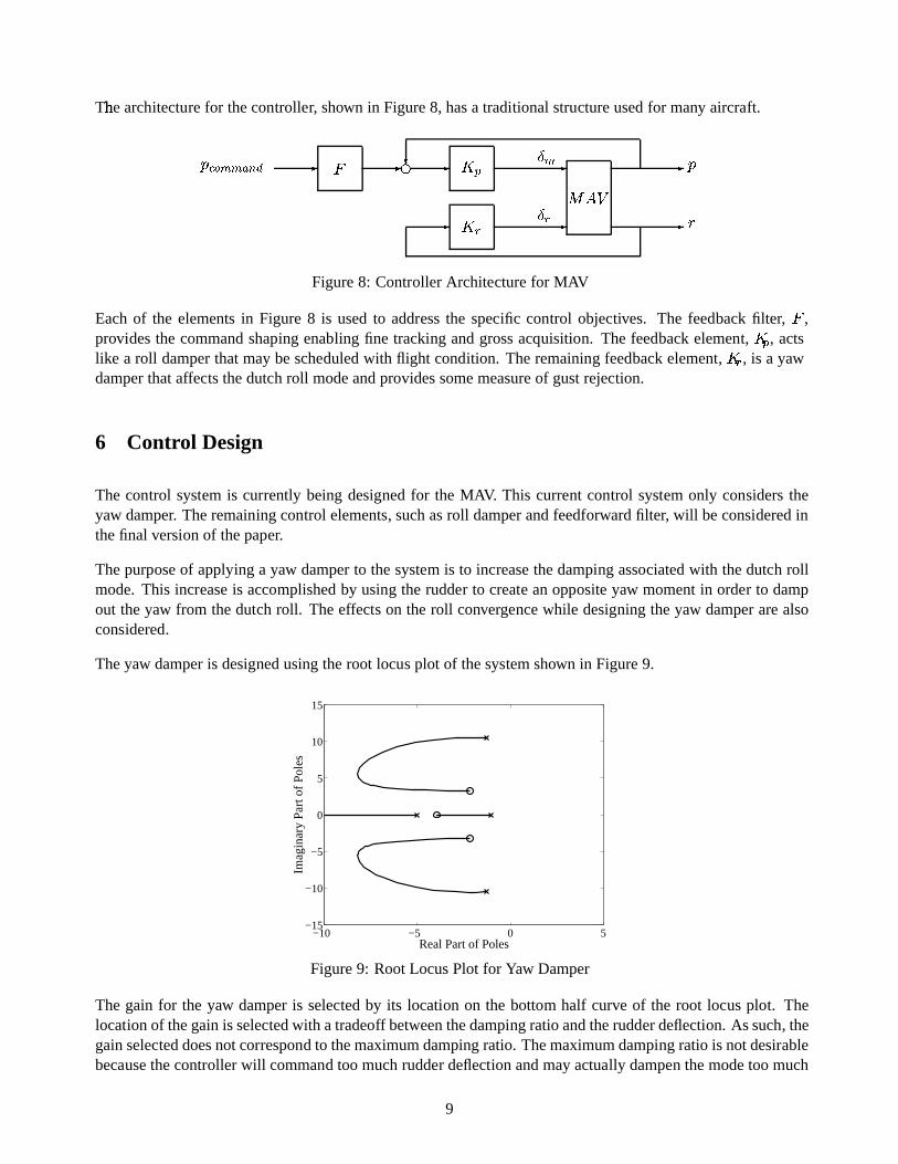
The� architecture for thecontroller, shown in Figure8, hasa traditional structureusedfor many aircraft.,ZY � I[I]\S^ R _ ` _Na _ b M _G Ib K _G K cedgf _h ,
__ -Figure8: Controller Architecturefor MAV
Eachof the elementsin Figure 8 is usedto addressthe specific control objectives. The feedback filter, ` ,providesthe commandshaping enabling fine tracking andgrossacquisition. The feedbackelement, b M , actslike a roll damperthatmaybescheduledwith flight condition. Theremaining feedbackelement, b K , is a yawdamperthataffects thedutch roll modeandprovidessomemeasureof gustrejection.
6 Control Design
The control system is currently beingdesignedfor the MAV. This current control system only considerstheyaw damper. Theremaining control elements, suchasroll damperandfeedforwardfilter, will beconsideredinthefinal version of thepaper.
Thepurposeof applying a yaw damperto thesystem is to increasethedamping associatedwith thedutch rollmode.This increaseis accomplishedby using the rudder to create anoppositeyaw momentin order to dampout theyaw from thedutch roll. Theeffects on the roll convergencewhile designing theyaw damperarealsoconsidered.
Theyaw damperis designedusingtheroot locus plot of thesystemshown in Figure9.
−10 −5 0 5−15
−10
−5
0
5
10
15
Real Part of Poles
Imag
inar
y P
art o
f Pol
es
Figure9: RootLocusPlot for Yaw Damper
The gain for the yaw damperis selected by its location on the bottom half curve of the root locus plot. Thelocation of thegainis selectedwith atradeoff betweenthedampingratioandtherudderdeflection. As such, thegainselecteddoesnotcorrespond to themaximumdampingratio. Themaximumdampingratio is notdesirablebecausethecontroller will command too muchrudder deflection andmayactually dampen themodetoo much
9
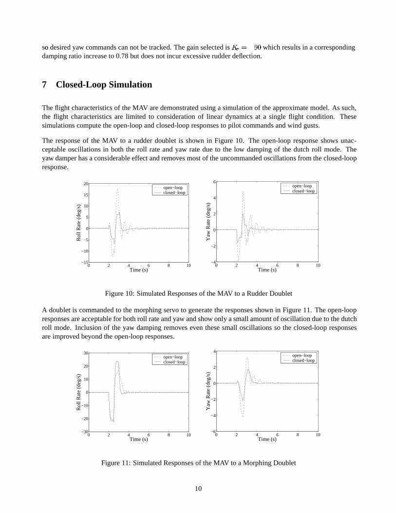
soi desired yaw commandscannot betracked. Thegainselectedis b K 3 ��=�� which results in acorrespondingdamping ratio increaseto 0.78but doesnot incur excessive rudder deflection.
7 Closed-Loop Simulation
Theflight characteristics of theMAV aredemonstratedusinga simulationof theapproximatemodel.As such,the flight characteristics are limited to consideration of linear dynamics at a single flight condition. Thesesimulationscompute theopen-loop andclosed-loop responsesto pilot commands andwind gusts.
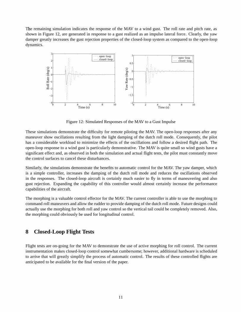
The responseof the MAV to a rudder doublet is shown in Figure10. The open-loop responseshows unac-ceptable oscillations in both the roll rateandyaw ratedueto the low damping of the dutch roll mode. Theyaw damperhasaconsiderable effectandremovesmostof theuncommandedoscillations from theclosed-loopresponse.
0 2 4 6 8 10−15
−10
−5
0
5
10
15
20
Rol
l Rat
e (d
eg/s
)
Time (s)
open−loopclosed−loop
0 2 4 6 8 10−4
−2
0
2
4
6
Yaw
Rat
e (d
eg/s
)
Time (s)
open−loopclosed−loop
Figure10: SimulatedResponsesof theMAV to a Rudder Doublet
A doublet is commandedto themorphing servoto generatetheresponsesshown in Figure11. Theopen-loopresponsesareacceptablefor bothroll rateandyaw andshow only asmallamount of oscillation dueto thedutchroll mode. Inclusion of the yaw dampingremoveseven thesesmall oscillationsso the closed-loop responsesareimprovedbeyond theopen-loop responses.
0 2 4 6 8 10−30
−20
−10
0
10
20
30
Rol
l Rat
e (d
eg/s
)
Time (s)
open−loopclosed−loop
0 2 4 6 8 10−6
−4
−2
0
2
4
Yaw
Rat
e (d
eg/s
)
Time (s)
open−loopclosed−loop
Figure11: SimulatedResponsesof theMAV to a Morphing Doublet
10
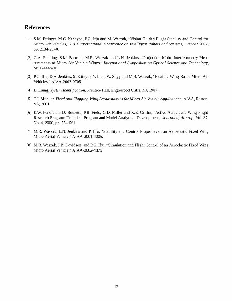
The� remaining simulation indicatesthe responseof the MAV to a wind gust. The roll rateandpitch rate,asshown in Figure12, aregenerated in responseto a gustrealizedasan impulse lateral force. Clearly, the yawdampergreatly increasesthegustrejection propertiesof theclosed-loop system ascomparedto theopen-loopdynamics.
0 2 4 6 8 10−4
−3
−2
−1
0
1
2
3
Rol
l Rat
e (d
eg/s
)
Time (s)
open−loopclosed−loop
0 2 4 6 8 10−2
−1.5
−1
−0.5
0
0.5
1
Yaw
Rat
e (d
eg/s
)
Time (s)
open−loopclosed−loop
Figure12: SimulatedResponsesof theMAV to a GustImpulse
Thesesimulations demonstratethe difficulty for remotepiloting the MAV. Theopen-loop responsesafter anymaneuver show oscillations resulting from the light damping of the dutchroll mode. Consequently, the pilothasa considerable workload to minimize the effectsof the oscillations andfoll ow a desired flight path. Theopen-loop responseto a wind gustis particularly demonstrative. TheMAV is quitesmallsowind gustshave asignificant effect and, asobservedin boththesimulation andactual flight tests, thepilot mustconstantly movethecontrol surfacesto cancel these disturbances.
Similarly, thesimulationsdemonstratethebenefitsto automaticcontrol for theMAV. Theyaw damper, whichis a simple controller, increasesthe damping of the dutch roll modeand reducesthe oscillations observedin the responses. The closed-loop aircraft is certainly much easier to fly in termsof maneuvering and alsogust rejection. Expanding the capability of this controller would almostcertainly increase the performancecapabilities of theaircraft.
Themorphing is a valuable control effector for theMAV. Thecurrent controller is ableto usethemorphing tocommandroll maneuversandallow therudder to providedamping of thedutchroll mode.Futuredesignscouldactually usethemorphing for bothroll andyaw control sothevertical tail could becompletely removed. Also,themorphing could obviously beused for longitudinal control.
8 Closed-Loop Flight Tests
Flight tests areon-going for theMAV to demonstratetheuseof active morphing for roll control. Thecurrentinstrumentation makesclosed-loop control somewhatcumbersome;however, additional hardware is scheduledto arrive that will greatly simplify theprocessof automaticcontrol. Theresults of these controlled flights areanticipatedto beavailable for thefinal version of thepaper.
11
Referj
ences
[1] S.M. Ettinger, M.C. Nechyba, P.G. Ifju andM. Waszak,“V ision-GuidedFlight Stability andControl forMicro Air Vehicles,” IEEE International Conference on Intelligent Robotsand Systems, October2002,pp.2134-2140.
[2] G.A. Fleming, S.M. Bartram,M.R. Waszakand L.N. Jenkins, “Projection Moire Interferometry Mea-surements of Micro Air Vehicle Wings,” International Symposium on Optical Scienceand Technology,SPIE-4448-16.
[3] P.G. Ifju, D.A. Jenkins,S.Ettinger, Y. Lian, W. ShyyandM.R. Waszak, “Flexible-Wing-BasedMicro AirVehicles,” AIAA-2002-0705.
[4] L. Ljung, SystemIdentification, Prentice Hall, EnglewoodClif fs, NJ,1987.
[5] T.J.Mueller, FixedandFlapping Wing Aerodynamicsfor Micro Air VehicleApplications, AIAA, Reston,VA, 2001.
[6] E.W. Pendleton, D. Bessette, P.B. Field, G.D. Miller andK.E. Griffin, “Active Aeroelastic Wing FlightResearch Program:Technical ProgramandModel Analytical Development,” Journal of Aircraft, Vol. 37,No. 4, 2000, pp.554-561.
[7] M.R. Waszak,L.N. Jenkins andP. Ifju, “Stability andControl Properties of an Aeroelastic Fixed WingMicro Aerial Vehicle,” AIAA-2001-4005.
[8] M.R. Waszak, J.B.Davidson,andP.G. Ifju, “Simulation andFlight Control of anAeroelastic FixedWingMicro Aerial Vehicle,” AIAA-2002-4875
12