Embed Size (px)
Citation preview

ISO 9001 : 2000
Catalog # 1005
Manufacturer of precision Disc Springssince 1969
ROLEX COMPANYDivision of the Chestnut Group, Inc.
385 Hillside Avenue, Hillside NJ 07205Phone 973 926 0900 Fax 973 926 5626

CASOS TIPICOS DE USOSRadiadores de Maquinaria para Movimiento de Tierras
Al tener un apriete flexible y dinámico con posibilidades de duplicar y triplicar la carga montando una golilla sobre la otra como esta explicado en la pagina 2, nos permite no solamente aumentar
la carga, lo cual es imposible para los sistemas de nuestra competencia, sino que podemos montar 1, 2 o 3 golillas en serie, sobreponer golillas invertidas, como también se explica en la
pagina 2, obteniendo ahora un empaque dinámico y flexible.
La mejor descripción de una Golilla BELLEVILLE, es que con ella cambia un apriete rígido por un apriete flexible, dinámico y armónico.
En usos donde es necesario tensionar los rodamientos para que trabajen en forma vertical o perpendicular a los ejes, lo cual aumenta la vida útil de los rodamientos y elimina el exceso de
ruido (ver paginas 32 y 34)
Cada cliente tiene un sinnúmero de usos. Los que ira descubriendo y solucionando problemas permanentes, reduciendo sus niveles de mantención.
Y sin olvidar nunca…….. se pagan solas, por la economía resultante
¿DONDE Y POR QUE SE USA LA GOLILLA BELLEVILLE?
En lugares donde hay grandes vibraciones permanentes.
Golillas BELLEVILLES para asegurar que las tuercas de los revestimientos de los chutes no se suelten por la vibración al igual que los harneros y estos se mantengan funcionando hasta su
siguiente mantención.
Utilizadas en Líneas de PIPING en los sectores donde hay permanentes filtraciones, las Golillas BELLEVILLES absorben vibraciones eliminando la filtración y protegiendo la empaquetadura. (ver
pagina 21)
En Válvulas que se abren en su parte superior, para cambiar los asientos de los mismos, para evitar que se fisuren las empaquetaduras y estas filtren. (ver pagina 28 y 29)
Estos conjuntos que se pueden construir a discreción y necesidad del cliente para un uso determinado, solucionan los problemas permanentes de solturas de pernos y tuercas,
ABSORBIENDO GOLPES Y VIBRACIONES, como sucede en los aprietes rígidos, la penetración en las piezas apretadas que actúan como sufrideras.
El montar golillas invertidas, da una solución donde se requieren juntas elásticas permanentes para trabajos continuos.

Basic Information for measurement and function of Disc Spring - - - - - - - -- - - - - - - - - - 2
Rolex Standard Springs - - - - - - - - - - - - - - - - - - - - - - - - - - - - - -- - - - - - - - - 3
Rolex Specialty Springs - - - - - - - - - - - - - - - - - - - - - - - - - - - - - -- - - - - - - - - 4
Special materials and Customer Services - - - - - - - - - - - - - - - - - - - - - - - - - - 5
Military Specifications - - - - - - - - - - - - - - - - - - - - - - - - - - - - - - - - - - - - - - - - - - - - 6-7
AM and SAM Series / Precision Spring Tolerance - - - - - - - - - - - - - - - - - - - - - - - - - - 8
AM Series Precision Spring Specification (in mm and Newtons) - - - - - - - - - - - - - - 9-12
AM Series Precision Spring Specification (in inches and pounds) - - - - - - - - - - - - 13-16
AI and AK Series / Standard Spring Tolerance - - - - - - - - - - - - - - - - - - - -- - - - - - - - 17
AI Series Disc Springs For Bolting Applications - - - - - - - - - - - - - - - - - - - - - - - - - 18-19
SP Series Springs (High Strength) for Heavy Bolted Sections - - - - - - - - -- - - - - - - - 20
National USS High Strength Stainless Steel Flat Washers - - - - - - - - - - - - - - - - - - - 20
FL & MFL Flange Spring Discs for Flange Applications - - - - - - - - - - - - - -- - - - - - - - 21
NDS Series Disc Springs (High Strength) Live Loading - - - - - - - - - - - - - -- - - - - - - - 30
AK Series Disc Springs for Use With Ball Bearings - - - - - - - - - - - - - - - - -- - - - - - 31-34
Contact Belleville Springs - - - - - - - - - - - - - - - - - - - - - - - - - - - - - - - - - - - - - - - - - - 35
METODO PARA CALCULAR CARGA Y TORQUE DEL PERNO- - -- - - - - - - - - - 19
pg1
ROLEX COMPANY CATALOG
Table of Contents

NOMENCLATURE OF A CONICAL SPRING
OD = Outside DiameterID = Inside Diameter
t or TH = ThicknessOH = Overall Height
h or d = Cone or Dish Height
Springs in parallel increase the potentialforce by the number of springs being used.
3 Springs in parallel = 3 * the force of one.
If one spring can develop 100 pounds of clamping force, 3 in parallel can develop 300 pounds of clamping force. The potential to develop a high coefficient of friction exists in a parallel stack due to the friction that is created on the surface contacts. Stacks larger then three tend to develop a high, unpredictable, coefficient of friction. A stack larger then three can not be predicted with any degree of accuracy because friction will cause risers in loads during the compression phase and dips in loads during the releasing phase. These are caused by a surface friction grabbing effect that prevents the surfaces moving smoothly across each other. The effect tends to be present in both the compression and releasing cycles.
Springs stacked in series increase the travel of thespring by the number of springs in the stack whileretaining the potential force of only one across the span of the stack.
Example: 6 springs in series will allow the springsto travel 6 times the distance of a single springwhile retaining the potential force of only one.
If one spring can develop 100 pounds of clampingforce at 75% of its travel height, then 6 (or more) springs will produce the same 100 pounds force at 75% of the total travel distance of the stack.
If a single spring, at .020" travel, is 75% deflection and develops 100 pounds of force, then a series stack of 6 will need to travel 6 times the deflection distance or .120", 75% of the stack travel height, to produce the same100 pounds of force. The formula is:
Stack force height = Single spring force height * the number of springs in the stack.
Unlike the parallel stack, the coefficient of friction plays less a roll in a series stack. However, larger series stacksmade of numbers greater than ten, tend to develop an unpredictable coefficient of friction around the contact edges that make it difficult to predict the accuracy of load points. These tend to be identified as sticking points and can produce a gripping or popping sound as the stack moves through the compression cycle. Numerous preventive measures such as lubracants, a larger radius or bearing flats may be specified to aid in reducing these effects.
Pg 2
6 SPRINGS IN SERIES SERIES SPRING STACK
Rolex CompanyBasic Information for measurement and function of a Disc Spring
CONICAL SPRING
3 SPRINGS IN PARALLEL PARALLEL SPRING STACK

Pg 3
We are not limited to manufacturing springs listed in our catalog. We have the knowledge, experience, and development programs to design springs to meet most any application. We have manufactured springs from a wide veriaty of materials to meet our customers special applications. Please contact our sales department with any special material requirements.
6. AK Series springs are specifically designed as preloading springs for use with radial ball bearings. They are made from C1075 material and are intended to maintain the positioning accuracy of the bearing with no endplay and minimize vibration and shaft deflection. AK series springs are intended to meet both Metric and Inch standard sizes.
for the FL and MFL series springs. However, they are primarily designed to handle applications demanding much higher load and/or temperature. NDS parts are normally made from H11/H13 steel and can produce flat loads up to 310,000 pounds and, under most conditions, can withstand temperatures up of 1100° F (500° C).
and/or mechanical shock. Applications include piping construction, compression joints, steam piping joints, valve and pump connections, and other similar applications. The FL and MFL series are normally manufactured from 17/7 PH stainless steel.
5. NDS Series flange springs are used to fill the application needs similar to those described
the effects of thermal expansion and contraction. The SP series are normally manufactured from High Carbon or Alloy steel; AISI C1075 or 6150 material.
4. FL (inch) and MFL (metric) series flange springs are primarily designed for pipe flange applications. They are intended to deflect and move with the bolted joint in the event of thermal
designated stress limits. Like the AM series the AI parts are typically manufactured from High Carbon or Alloy steel; AISI C1075 or 6150 material.
3. SP Series are specifically designed for heavy bolted applications such as those required for bus bar and transformer applications. They are used wherever there is a need to overcome
from High Carbon or Alloy steel; AISI C1075 or 6150 material.
2. AI Series springs are designed to maintain load tension in light bolted assemblies, where a constant load is required. Although this series is primarily designed for bolted applications, they may also be used in dynamic applications as long as the application does not exceed the
Rolex Standard Springs
1. AM Series are precision springs geared to the metric community and manufactured utilizing DIN 2092 and DIN 2093 as guidelines. AM series springs are designed to meet high peformance requirements of dynamic spring applications. They are typically manufactured

discribed below:
pounds are required.
pg4
Rolex Specialty Springs Other than the springs listed in our catalog of parts. We can also provide aid in design and manufacturing for a number of specialty spring types including, but not limited to, those
a. Curve springs - utilized where very minor loads, usually in ounces or low
requirements
b. Diaphragm, Slotted, or Finger springs (Inside or Out) - are designed to meet a number of low load applications and are generally used in low load applications such as those found in transmission and clutch applications.
c. Wave Washers - like the diaphragm spring, are designed to meet low load

All parts made of materials other than steel are specials. Load and dimensional tolerance targets will vary from those published for steel.
When making parts from materials other than steel, loads are targeted and dimensional characteristics are selected to achieve the load target. Load targets are also +/- 20% to allow for variences in dimensional characteristics of commercially available material.
Theoretical design analysis specifications and load deflection curves are available upon request for numerous material types to aid in your project design needs.
Series, parallel and series-parallel stacks can be assembled, lubricated, and wrapped in a plastic shrink-wrap that can be easily mounted and shrink-wrap removed after the spring stack has been placed in the customer’s assembly.
In some cases Rolex can mount springs directly onto a customers assembly and ship completed assemblies back to the customer.
Rolex wants to be the supplier of choice and is eager to aid in the area of service, design and application that may accommodate our customer’s needs.
pg5
Rolex Special Customer Services Part stacking arrangements, partial assemblies, and testing may be accommodated to meet customer needs.
Rolex Special Materials
Material: MIL-W-12133/1 for spring steel (i.e. C 1075),
Part number system:The part number consists of the letter "M", the basic specification number, followed by a dash number and a finish code leter.
Part No.: The MIL-W-12133/1breakdown of the part number is as follows:
M12133/ 1 - 1 P
See Example BelowTne Dash Number identifies the Size in inches from lists belowThe Slash Number identifies the material (type 1 for steel or 2 for stainless)Standard series specification number
Example: M12133/1-1 Part number with no ending letter indicates a plain (no finish) part
M12133/1-1 P The 'P' is for Electrodeposition Cadmium plate (Per QQ-P-416 Type II Class 2)
M12133/1-1 M The 'M' is for Mechanical Cadmium desposition (Per MIL-C-81562 Type II Class 2)
M12133/1-1 Z The 'Z' is for Mechanical Zinc desposition with supplementary Chromate (Per MIL-C-81562 Type II Class 2) or Electrodeposition Zinc plate (Per ASTM B633, Fe/Zn 13, Type II).
Note: Certain plating increases thickness. Dimensions are correct prior to plating.
MIL-W-12133/1-
Dash Deflection Load Bolt Dia.No. Dim. Minus Dim. Plus Dim. Range Dim. Range Ref. +/- 10% Ref.62 .250 - 0.015 .125 + 0.015 .009 +/- 0.001 .017 +/- 0.003 0,006 14 0,1121 .250 - 0.015 .125 + 0.015 .013 +/- 0.001 .020 +/- 0.003 0,005 37 0,11269 .315 - 0.015 .125 + 0.010 .012 +/- 0.001 .022 +/- 0.003 0,0072 26 0,11260 .281 - 0.015 .138 + 0.015 .015 +/- 0.001 .023 +/- 0.003 0,006 53 0,1382 .312 - 0.015 .156 + 0.015 .017 +/- 0.001 .025 +/- 0.003 0,006 63 0,13861 .343 - 0.015 .164 + 0.015 .016 +/- 0.001 .023 +/- 0.003 0,005 35 0,16463 .375 - 0.015 .195 + 0.015 .020 +/- 0.001 .030 +/- 0.003 0,008 96 0,1903 .375 - 0.015 .195 + 0.015 .015 +/- 0.001 .027 +/- 0.003 0,009 49 0,1904 .500 - 0.020 .258 + 0.020 .020 +/- 0.001 .036 +/- 0.003 0,011 78 0,25064 .500 - 0.020 .258 + 0.020 .018 +/- 0.001 .034 +/- 0.003 0,012 64 0,2505 .625 - 0.020 .317 + 0.020 .032 +/- 0.002 .051 +/- 0.005 0,014 252 0,31365 .750 - 0.020 .382 + 0.020 .028 +/- 0.002 .050 +/- 0.005 0,017 144 0,3756 .750 - 0.025 .382 + 0.020 .032 +/- 0.002 .054 +/- 0.005 0,016 203 0,37566 .750 - 0.025 .382 + 0.020 .040 +/- 0.002 .059 +/- 0.005 0,014 334 0,43868 .875 - 0.020 .442 + 0.010 .045 +/- 0.002 .067 +/- 0.005 0,011 286 0,4387 1.000 - 0.025 .445 + 0.025 .035 +/- 0.002 .067 +/- 0.005 0,024 218 0,43867 1.000 - 0.025 .505 + 0.025 .050 +/- 0.002 .079 +/- 0.005 0,019 493 0,5008 1.000 - 0.025 .512 + 0.025 .039 +/- 0.002 .079 +/- 0.005 0,027 369 0,5009 1.102 - 0.025 .512 + 0.025 .049 +/- 0.002 .083 +/- 0.005 0,025 503 0,50010 1.375 - 0.030 .637 + 0.025 .059 +/- 0.002 .102 +/- 0.008 0,032 754 0,62511 1.500 - 0.030 .761 + 0.030 .059 +/- 0.002 .114 +/- 0.008 0,041 861 0,75012 1.500 - 0.030 .761 + 0.030 .078 +/- 0.002 .121 +/- 0.008 0,032 1431 0,75013 1.750 - 0.030 .880 + 0.030 .089 +/- 0.003 .128 +/- 0.008 0,032 1333 0,87514 2.000 - 0.040 1.016 + 0.030 .079 +/- 0.003 .136 +/- 0.008 0,044 1184 1,00015 2.373 - 0.040 1.016 + 0.030 .098 +/- 0.003 .137 +/- 0.008 0,059 2020 1,000
pg6
M12133/1-14M12133/1-15
M12133/1-10M12133/1-11M12133/1-12M12133/1-13
M12133/1-7M12133/1-67M12133/1-8M12133/1-9
M12133/1-65M12133/1-6M12133/1-66M12133/1-68
M12133/1-3M12133/1-4M12133/1-64M12133/1-5
M12133/1-60M12133/1-2M12133/1-61M12133/1-63
Part No.M12133/1-62M12133/1-1M12133/1-69
BELLEVILLE SPRINGS TO MIL-W-12133/1 FOR STEELMilitary specifications
(Spring Tension Washers)
Rolex OD & Tolerance ID & Tolerance t & Tolerance OH & Tolerance

Material: MIL-W-12133/2 301, 302 or 17/7 PH Stainless steel
Part number system:
The part number consists of the letter "M", the basic specification number, followed by a dash number.
Part No.: The MIL-W-12133/2 breakdown of the part number is as follows:
M12133/ 2 - 125
See Example BelowTne Dash Number identifies the Size in inches from lists belowThe Slash Number identifies the material (type 1 for steel or 2 for stainless)Standard series specification number
Indicate a stainless steel part with .250 OD x .125 ID x .013 thk x .020 free height, cleaned, descaled, and passivated (Per ASTM-A380)
MIL-W-12133/2-
Dash OH Deflection Load FLAT Bolt Dia.No. Dim. Minus Dim. Plus Dim. Range Nom. Ref. Ref. Range Load Ref. *
M12133/2-93 093 0,187 - 0.020 0,093 + 0.020 0,010 +/- 0.001 0,015 0,002 15-18 27 0,094 *M12133/2-125 125 0,250 - 0.020 0,125 + 0.020 0,013 +/- 0.001 0,020 0,003 22-27 45 0,125 *M12133/2-156 156 0,312 - 0.020 0,156 + 0.020 0,017 +/- 0.001 0,025 0,004 34-49 77 0,156 *M12133/2-190 190 0,375 - 0.020 0,190 + 0.020 0,020 +/- 0.001 0,030 0,005 50-72 110 0,188 *
200 0,375 - 0.020 0,190 + 0.020 0,015 +/- 0.001 0,027 0,006 33-45 55 0,188M12133/2-255 255 0,500 - 0.030 0,255 + 0.030 0,025 +/- 0.001 0,038 0,007 80-109 157 0,250 *
400 0,625 - 0.030 0,317 + 0.030 0,022 +/- 0.002 0,042 0,010 56-85 104 0,313M12133/2-317 317 0,625 - 0.030 0,317 + 0.030 0,032 +/- 0.002 0,048 0,008 123-175 259 0,313 *M12133/2-380 380 0,750 - 0.035 0,380 + 0.035 0,040 +/- 0.002 0,059 0,010 210-281 418 0,375 *M12133/2-505 505 1,000 - 0.035 0,505 + 0.035 0,050 +/- 0.002 0,075 0,013 308-428 596 0,500M12133/2-567 567 1,125 - 0.035 0,567 + 0.035 0,056 +/- 0.002 0,084 0,014 374-499 745 0,563 *M12133/2-630 630 1,250 - 0.040 0,630 + 0.040 0,062 +/- 0.002 0,092 0,015 440-582 876 0,625 *M12133/2-755 755 1,500 - 0.040 0,755 + 0.040 0,045 +/- 0.002 0,093 0,024 239-301 367 0,750 *M12133/2-100 100 2,000 - 0.040 1,000 + 0.040 0,065 +/- 0.002 0,130 0,032 547-651 842 1,000M12133/2-900 900 2,500 - 0.040 1,250 + 0.040 0,125 +/- 0.005 0,180 0,030 1683-2161 3268 1,250
Parts normally stocked = *
pg7
Part No.Rolex OD & Tolerance ID & Tolerance t & Tolerance
BELLEVILLE SPRINGS TO MIL-W-12133/2 FOR STAINLESS STEELMilitary specifications
(Spring Tension Washers)
Rolex only provides parts meeting the MIL-W-12133/2 requirement as passivated.

v
Range Tolerance Range ToleranceID + 0.102 ID + 0,13 ID + 0.004 ID + 0,005 + 25,0%OD - 0.102 OD - 0,13 OD - 0.004 OD - 0,005 - 7,5%
> 3.0 ID + 0.127 ID + 0,15 > 0.118 ID + 0.005 ID + 0,006 + 15,0% < = 6.0 OD - 0.127 OD - 0,15 < = 0.236 OD - 0.005 OD - 0,006 - 7,5% > 6.0 ID + 0.152 ID + 0,18 > 0.236 ID + 0.006 ID + 0,007 + 10,0% < = 10.0 OD - 0.152 OD - 0,18 < = 0.394 OD - 0.006 OD - 0,007 - 5,0% > 10.0 ID + 0.178 ID + 0,20 > 0.394 ID + 0.007 ID + 0,008 + 5,0% < = 18.0 OD - 0.178 OD - 0,20 < = 0.709 OD - 0.007 OD - 0,008 < 0,70 - 0,025 < 0,0276 +/- 0,001 - 5,0% > 18.0 ID + 0.203 ID + 0,23 > 0.709 ID + 0.008 ID + 0,009 > = 0,70 > = 0,0276 < = 30.0 OD - 0.203 OD - 0,23 < = 1.180 OD - 0.008 OD - 0,009 < 2,25 < 0,088 > 30.0 ID + 0.254 ID + 0,28 > 1.180 ID + 0.010 ID + 0,011 > = 2,25 > = 0,088 < = 50.0 OD - 0.254 OD - 0,28 < = 1.970 OD - 0.010 OD - 0,011 < 3,00 < 0,118 > 50.0 ID + 0.305 ID + 0,33 > 1.970 ID + 0.012 ID + 0,013 > = 3,00 > = 0,118 < = 80.0 OD - 0.305 OD - 0,33 < = 3.150 OD - 0.012 OD - 0,013 < 4,00 < 0,157 < 1,00 < 0,039 > 80.0 ID + 0.356 ID + 0,38 > 3.150 ID + 0.014 ID + 0,015 > = 4,00 +/- 0,127 > = 0,157 +/- 0,005 > = 1,00 > = 0,039 < = 120 OD - 0.356 OD - 0,38 < = 4.720 OD - 0.014 OD - 0,015 < 4,25 < 0,157 > 120 ID + 0.406 ID + 0,43 > 4.720 ID + 0.016 ID + 0,017 > = 4,25 > = 0,157 < = 180 OD - 0.406 OD - 0,43 < = 7.090 OD - 0.016 OD - 0,017
ID + 0.457 ID + 0,48 ID + 0.018 ID + 0,019OD - 0.457 OD - 0,48 OD - 0.018 OD - 0,019
< = 0,51 +/- 0,05 < = 0,020 +/- 0,002> 0,51 > 0,020< = 1,27 < = 0,050> 1,27 > 0,050
t Range OH Tol. t Range OH Tol. < = 2,34 < = 0,092+ 0.10 + 0,11 + .004 + 0,0045 > 2,34 > 0,092- 0.05 - 0,06 - .002 - 0,0025 < = 3,18 < = 0,125
> 1.25 + 0.15 + 0,17 > .049 + .006 + 0,0065 > 3,18 > 0,125< = 2.00 - 0.08 - 0,09 < = .078 - .003 - 0,0035 < = 4,95 < = 0,195> 2.00 + 0.30 + 0,32 > .078 + .012 + 0,0125 > 4,95 +/- 0,25 > 0,195 +/- 0,010< = 3.00 - 0.10 - 0,11 < = .118 - .004 - 0,0045> 3.00 + 0.30 + 0,32 > .118 + .012 + 0,0125< = 6.00 - 0.15 - 0,17 < = .236 - .006 - 0,0065
+ 0.30 + 0,32 + .012 + 0,0125- 0.30 - 0,32 - .012 - 0,0125
Pg8
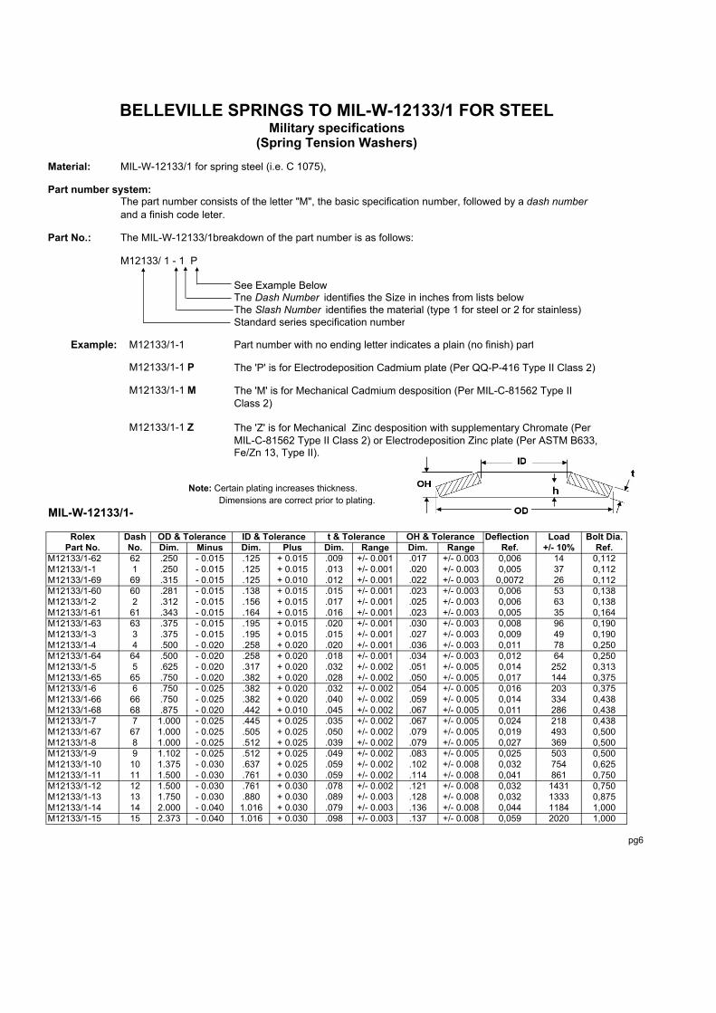
The tolerances on this page are for the AM and SAM series parts. The material used for the AM series is either C1075 or AISI 6150 carbon steel. When requesting parts made of 17/7 PH stainless steel material use the letter "S" in front of the exising part number for example for carbon steel AM-502520 use SAM-502520 for the same part made of 17/7 PHstainless steel Use the columns identified as SAMfor dimensional ond or tolerance differences required for ALL 17/7 PH stainless steel parts.
> 6.00 > .236
Desingn Note: stainless steel material thickness is different than steel and is subject to commercial availability. The Overall height will be used to compensate the difference in load due to the difference in thickness. ALL Stainless Steel materials will utilize the SAM specification above with the exception of materials not available in standard tolerance range. In those cases the closest material tolerance will be used.
For availability of other material types and achievable tolerances, please call GSA S.A., Rolex Sales or Engineering for assitance.
0,13 +/- 0,005
+/- 0,20 +/- 0,008
OH Tol. +/- 0,004
< = 1.25 < = .049 +/-
by Part Thickness Stainless by Part Thickness Stainless +/- 0,10OH Tol.
AM Series INCH SAM INCHNote: Part numbers and dimensions in this catalog are
subject to manufacturer´s change withhowt notice.OVERALL HEIGHT TOLERANCE +/- 0,08 +/- 0,003AM Series MM SAM MM
Please consult Rolex Company for the correctRange Tolerance Range Tolerance hardness used for other stainless material. > 180 > 7.090 SAM Series MM SAM Series INCH
THICKNESS ( t ) TOLERANCE 42 - 48 Minimum 3817/7 PH Stainless Steel The SAM hardness above, is for 17/7 material.
46 - 51 Minimum 38
44 - 49 Minimum 38
MM INCH HRc Stainless+/- 0,102 +/- 0,004
AM Series Tolerance SAMThickness Range Rockwell HRc+/- 0,076 +/- 0,003
> 6.00 > .236 +/- 20%
+/- 0,051 +/- 0,002 HARDNESS TOLERANCE
Range Tolerance Range Tolerance
+/- 20%AM Series MM AM Series INCH < = 6.00 < = .236
THICKNESS ( t ) TOLERANCE < = 3.00 < = .118Carbon Steel AISI C1075 or AISI 6150 > 3.00 > .118
+/- 20%
> 1.25 > .049 +/- 20%
< = 3.0 < = 0.118 < = 1.25 < = .049
Thickness Range AM SAMTolerance Tolerance MM INCH Series Series
Carbon Steel Tolerance Carbon Steel Tolerance
Rolex Company AM / SAM Series Precision Spring Tolerances
OUTSIDE & INSIDE DIAMETER TOLERANCE LOAD TOLERANCEAM Series (MM) SAM AM SERIES (INCH) SAM Operation Load Tolerance
Tolerances on this page are both AM and SAM series parts. The default materials for the AM series parts are carbon steel (AISI C1075 or AISI 6150) and for standars SAM seriesparts is 17/7 PH (AMS-5528) stainless steel material. Consul Rolex Sales or Engineering for availability of other material types and achievable tolerances.

AM SERIES PRECISION SPRING SPECIFICATIONSIn mm and Newtons
Fatigue life is dependant on the users application and can notbe calculated without the user's application requirements.
Load f Stress f Load f Stress fin Deflec- N/ in Deflec- N/
Part No * OD ID t h OH h/t Newtons tion sqmm % Newtons tion sqmm %AM-63203 * 6,0 3,2 0,3 0,2 0,4 0,506 89 0,08 924 50% 129 0,11 1317 75%AM-83202 * 8,0 3,2 0,2 0,2 0,4 0,991 21 0,10 448 50% 31 0,20 752 100%AM-83203 * 8,0 3,2 0,3 0,3 0,5 0,836 84 0,12 800 50% 124 0,23 1276 90%AM-83204 * 8,0 3,2 0,4 0,2 0,6 0,507 102 0,07 572 35% 186 0,13 1297 63%AM-84202 * 8,0 4,2 0,2 0,3 0,4 1,249 36 0,12 786 50% 44 0,25 1303 100%AM-84203 * 8,0 4,2 0,3 0,3 0,5 0,840 95 0,13 1000 51% 119 0,18 1324 70%AM-84204 * 8,0 4,2 0,4 0,2 0,6 0,509 159 0,10 910 50% 226 0,15 1317 75%AM-103203 10,0 3,2 0,3 0,4 0,7 1,175 87 0,18 745 50% 114 0,35 1234 100%AM-103204 10,0 3,2 0,4 0,3 0,7 0,762 143 0,15 710 50% 202 0,24 1331 80%AM-103205 10,0 3,2 0,5 0,3 0,7 0,500 173 0,10 738 40% 264 0,16 1290 65%AM-104204 10,0 4,2 0,4 0,3 0,7 0,764 151 0,15 821 50% 230 0,27 1366 90%AM-104205 10,0 4,2 0,5 0,3 0,7 0,501 221 0,12 834 50% 314 0,19 1352 75%AM-105225 10,0 5,2 0,2 0,3 0,6 1,223 51 0,15 745 50% 65 0,30 1241 100%AM-105204 * 10,0 5,2 0,4 0,3 0,7 0,767 168 0,15 993 50% 215 0,21 1317 70%AM-105205 * 10,0 5,2 0,5 0,3 0,7 0,503 245 0,13 890 51% 349 0,19 1303 75%AM-124204 * 12,0 4,2 0,4 0,4 0,8 1,012 151 0,20 772 50% 219 0,40 1352 100%AM-124205 12,0 4,2 0,5 0,4 0,9 0,705 224 0,18 724 50% 320 0,28 1331 80%AM-124206 12,0 4,2 0,6 0,4 1,0 0,675 368 0,16 814 40% 512 0,24 1303 60%AM-125205 * 12,0 5,2 0,5 0,4 0,9 0,804 283 0,20 993 50% 359 0,28 1317 70%AM-125206 * 12,0 5,2 0,6 0,4 0,9 0,591 393 0,18 945 50% 519 0,25 1352 71%AM-126205 * 12,0 6,2 0,5 0,4 0,9 0,708 258 0,18 966 50% 352 0,27 1359 75%AM-126206 * 12,0 6,2 0,6 0,4 0,9 0,593 355 0,14 903 40% 501 0,21 1297 60%AM-135205 12,5 5,2 0,5 0,4 0,9 0,705 214 0,18 738 50% 333 0,32 1324 90%AM-136235 * 12,5 6,2 0,4 0,5 0,8 1,293 138 0,23 986 50% 160 0,34 1352 75%AM-136205 * 12,5 6,2 0,5 0,4 0,9 0,707 231 0,18 848 50% 359 0,32 1372 90%AM-136207 * 12,5 6,2 0,7 0,3 1,0 0,433 453 0,14 834 45% 635 0,20 1276 66%AM-147235 * 14,0 7,2 0,4 0,5 0,8 1,292 111 0,23 807 50% 137 0,45 1338 100%AM-147205 * 14,0 7,2 0,5 0,4 0,9 0,804 222 0,20 834 50% 334 0,36 1345 91%AM-147208 * 14,0 7,2 0,8 0,3 1,1 0,379 592 0,15 890 50% 809 0,21 1303 71%AM-155204 * 15,0 5,2 0,4 0,6 0,9 1,389 164 0,28 786 50% 190 0,55 1283 100%AM-155205 * 15,0 5,2 0,5 0,5 1,0 1,005 235 0,25 759 50% 342 0,50 1359 100%AM-155206 15,0 5,2 0,6 0,5 1,0 0,754 324 0,23 724 50% 475 0,38 1372 85%AM-155207 * 15,0 5,2 0,7 0,4 1,1 0,572 426 0,20 848 50% 568 0,28 1276 70%AM-156205 15,0 6,2 0,5 0,5 1,0 1,007 244 0,25 834 50% 346 0,48 1366 95%AM-156206 15,0 6,2 0,6 0,5 1,0 0,756 333 0,23 807 50% 510 0,41 1372 90%AM-156207 * 15,0 6,2 0,7 0,4 1,1 0,573 444 0,20 779 50% 621 0,30 1283 75%AM-158207 * 15,0 8,2 0,7 0,4 1,1 0,576 515 0,20 986 50% 679 0,28 1317 70%AM-158208 * 15,0 8,2 0,8 0,4 1,2 0,506 683 0,18 986 45% 941 0,26 1372 65%AM-168204 * 16,0 8,2 0,4 0,5 0,9 1,263 138 0,25 779 50% 173 0,50 1290 100%AM-168206 * 16,0 8,2 0,6 0,5 1,0 0,757 324 0,23 841 50% 497 0,41 1366 90%AM-168207 * 16,0 8,2 0,7 0,5 1,2 0,649 501 0,23 945 50% 688 0,34 1331 75%AM-168208 * 16,0 8,2 0,8 0,4 1,2 0,504 621 0,20 883 50% 888 0,30 1310 75%AM-168209 * 16,0 8,2 0,9 0,4 1,2 0,394 754 0,18 890 50% 1030 0,25 1303 70%AM-186204 * 18,0 6,2 0,4 0,6 1,0 1,515 133 0,30 614 50% 146 0,48 876 80%AM-186205 18,0 6,2 0,5 0,6 1,1 1,203 217 0,30 683 50% 284 0,60 1131 100%AM-186206 18,0 6,2 0,6 0,6 1,2 1,005 337 0,30 759 50% 488 0,60 1359 100%AM-186207 * 18,0 6,2 0,7 0,6 1,2 0,787 444 0,28 717 50% 648 0,47 1338 85%AM-186208 * 18,0 6,2 0,8 0,5 1,3 0,629 559 0,25 800 50% 781 0,38 1324 75%AM-188205 * 18,0 8,2 0,5 0,6 1,1 1,206 235 0,30 814 50% 302 0,60 1352 100%AM-188207 * 18,0 8,2 0,7 0,6 1,2 0,789 479 0,28 876 50% 697 0,47 1345 85%AM-188208 * 18,0 8,2 0,8 0,5 1,3 0,631 604 0,25 834 50% 883 0,40 1283 80%AM-188210 * 18,0 8,2 1,0 0,4 1,4 0,402 883 0,20 890 50% 1203 0,28 1303 70%AM-189245 * 18,0 9,2 0,4 0,6 1,0 1,343 195 0,30 848 50% 231 0,57 1359 95%AM-189207 * 18,0 9,2 0,7 0,5 1,2 0,717 444 0,25 848 50% 692 0,45 1372 90%AM-189210 * 18,0 9,2 1,0 0,4 1,4 0,403 936 0,20 883 50% 1278 0,28 1297 70%AM-208206 * 20,0 8,2 0,6 0,7 1,3 1,177 364 0,35 848 50% 470 0,67 1372 95%AM-208207 * 20,0 8,2 0,7 0,7 1,3 0,930 475 0,33 828 50% 692 0,62 1359 95%AM-208208 20,0 8,2 0,8 0,6 1,4 0,755 595 0,30 800 50% 914 0,54 1372 90%AM-208209 * 20,0 8,2 0,9 0,6 1,5 0,618 737 0,28 772 50% 1078 0,44 1352 80%AM-208210 * 20,0 8,2 1,0 0,6 1,5 0,553 994 0,28 890 50% 1327 0,39 1338 70%AM-201005 * 20,0 10,2 0,5 0,7 1,2 1,309 231 0,33 821 50% 284 0,66 1359 100%AM-201008 * 20,0 10,2 0,8 0,6 1,3 0,693 586 0,28 848 50% 879 0,47 1324 85%AM-201009 * 20,0 10,2 0,9 0,6 1,5 0,620 817 0,28 931 50% 1132 0,42 1317 75%AM-201010 * 20,0 10,2 1,0 0,6 1,5 0,555 1101 0,28 1007 50% 1464 0,39 1345 70%AM-201011 * 20,0 10,2 1,1 0,5 1,5 0,413 1136 0,23 876 50% 1549 0,32 1283 70%
pg9
OPERATIONAL LOAD LIMITSMINIMUM MAXIMUM
DIMENSIONAL CHARACTERISTICS

AM SERIES PRECISION SPRING SPECIFICATIONSIn mm and Newtons
Fatigue life is dependant on the users application and can notbe calculated without the user's application requirements.
Load f Stress f Load f Stress fin Deflec- N/ in Deflec- N/
Part No * OD ID t h OH h/t Newtons tion sqmm % Newtons tion sqmm %AM-201013 * 20,0 10,2 1,2 0,5 1,8 0,406 1349 0,18 759 35% 2055 0,28 1255 55%AM-201015 * 20,0 10,2 1,5 0,3 1,8 0,202 1864 0,15 966 50% 2592 0,21 1372 70%AM-221106 * 22,5 11,2 0,6 0,8 1,4 1,345 391 0,40 952 50% 453 0,65 1359 80%AM-221108 * 22,5 11,2 0,8 0,7 1,5 0,820 568 0,33 821 50% 879 0,62 1372 95%AM-221113 * 22,5 11,2 1,2 0,5 1,8 0,405 1438 0,25 883 50% 2006 0,35 1290 70%AM-238207 23,0 8,2 0,7 0,8 1,5 1,147 479 0,40 779 50% 639 0,81 1303 100%AM-238208 * 23,0 8,2 0,8 0,8 1,5 0,942 595 0,38 759 50% 870 0,72 1310 95%AM-238209 * 23,0 8,2 0,9 0,7 1,6 0,784 737 0,35 745 50% 1069 0,60 1317 85%AM-238210 * 23,0 8,2 1,0 0,7 1,7 0,703 981 0,35 793 50% 1336 0,53 1317 75%AM-231009 * 23,0 10,2 0,9 0,8 1,7 0,844 861 0,38 945 50% 1132 0,57 1324 75%AM-231010 * 23,0 10,2 1,0 0,7 1,7 0,704 1038 0,35 917 50% 1487 0,56 1359 80%AM-231013 * 23,0 10,2 1,2 0,7 1,9 0,526 1611 0,29 1000 45% 2219 0,43 1366 65%AM-231210 * 23,0 12,2 1,0 0,6 1,6 0,606 936 0,30 876 50% 1447 0,52 1372 85%AM-231213 * 23,0 12,2 1,2 0,6 1,8 0,487 1611 0,27 938 45% 2232 0,40 1310 65%AM-231215 * 23,0 12,2 1,5 0,5 2,0 0,336 1992 0,20 855 40% 2929 0,30 1331 60%AM-251010 25,0 10,2 1,0 0,8 1,8 0,754 936 0,38 800 50% 1376 0,64 1276 85%AM-251207 * 25,0 12,2 0,7 0,9 1,6 1,293 550 0,45 979 50% 639 0,68 1338 75%AM-251209 * 25,0 12,2 0,9 0,7 1,6 0,786 688 0,35 779 50% 1114 0,71 1352 100%AM-251210 * 25,0 12,2 1,0 0,8 1,8 0,808 1105 0,40 1014 50% 1398 0,57 1345 70%AM-251213 * 25,0 12,2 1,2 0,7 2,0 0,568 1708 0,36 986 50% 2268 0,50 1317 70%AM-251215 * 25,0 12,2 1,5 0,6 2,0 0,370 1979 0,25 869 45% 2791 0,36 1310 65%AM-281008 27,9 10,2 0,8 1,0 1,8 1,193 590 0,48 738 50% 768 0,96 1228 100%AM-281010 * 27,9 10,2 1,0 0,9 1,9 0,904 936 0,45 772 50% 1393 0,86 1359 95%AM-281013 * 27,9 10,2 1,2 0,8 2,0 0,645 1447 0,40 786 50% 2001 0,60 1317 75%AM-281015 * 27,9 10,2 1,5 0,7 2,3 0,469 2050 0,32 917 45% 2640 0,45 1276 64%AM-281210 * 27,9 12,2 1,0 1,0 2,0 0,957 1069 0,48 938 50% 1416 0,77 1366 80%AM-281213 * 27,9 12,2 1,2 0,9 2,1 0,687 1646 0,43 924 50% 2365 0,69 1372 80%AM-281215 * 27,9 12,2 1,5 0,8 2,3 0,504 2148 0,34 848 45% 2969 0,49 1310 65%AM-281408 * 27,9 14,2 0,8 1,0 1,8 1,262 728 0,51 1021 50% 839 0,71 1324 70%AM-281410 * 27,9 14,2 1,0 0,8 1,8 0,807 896 0,40 834 50% 1340 0,73 1345 90%AM-281413 * 27,9 14,2 1,2 0,9 2,1 0,689 1633 0,39 966 45% 2183 0,56 1324 65%AM-281415 * 27,9 14,2 1,5 0,7 2,1 0,436 2143 0,33 862 50% 2907 0,46 1276 70%AM-321210 31,5 12,2 1,0 1,1 2,1 1,106 1016 0,55 841 50% 1367 1,05 1366 95%AM-321213 * 31,5 12,2 1,2 1,0 2,2 0,765 1438 0,48 772 50% 2103 0,81 1290 85%AM-321215 * 31,5 12,2 1,5 0,9 2,3 0,569 2063 0,43 834 50% 2898 0,64 1366 75%AM-321608 * 31,5 16,3 0,8 1,1 1,8 1,321 626 0,53 869 50% 746 0,95 1345 90%AM-321613 * 31,5 16,3 1,2 0,9 2,1 0,727 1509 0,45 903 50% 2139 0,73 1338 80%AM-321615 * 31,5 16,3 1,5 0,9 2,4 0,607 2299 0,41 945 45% 3124 0,59 1303 65%AM-321618 * 31,5 16,3 1,8 0,7 2,5 0,403 2907 0,35 883 50% 3958 0,50 1297 70%AM-321620 * 31,5 16,3 2,0 0,8 2,8 0,382 3790 0,30 876 40% 5534 0,46 1372 60%AM-341210 * 34,0 12,2 1,0 1,3 2,3 1,256 1061 0,63 834 50% 1318 1,19 1338 95%AM-341213 * 34,0 12,2 1,2 1,1 2,3 0,885 1487 0,55 779 50% 2157 1,00 1317 90%AM-341215 * 34,0 12,2 1,5 1,0 2,5 0,669 2126 0,50 786 50% 2920 0,75 1317 75%AM-341413 * 34,0 14,3 1,2 1,2 2,4 0,928 1651 0,58 917 50% 2201 0,93 1372 80%AM-341415 * 34,0 14,3 1,5 1,1 2,6 0,705 2361 0,53 903 50% 3373 0,85 1372 80%AM-341615 * 34,0 16,3 1,5 1,1 2,6 0,706 2494 0,53 1007 50% 3226 0,74 1338 70%AM-341620 * 34,0 16,3 2,0 0,9 2,8 0,431 3550 0,35 807 40% 5143 0,52 1276 60%AM-361809 * 35,6 18,3 0,9 1,2 2,0 1,289 746 0,58 828 50% 919 1,16 1366 100%AM-361813 * 35,6 18,3 1,2 1,0 2,3 0,808 1353 0,51 814 50% 2099 0,96 1359 95%AM-361820 * 35,6 18,3 2,0 0,8 2,8 0,405 3861 0,40 903 50% 5254 0,57 1324 70%AM-401413 * 39,9 14,3 1,2 1,4 2,6 1,126 1562 0,70 807 50% 2117 1,41 1345 100%AM-401415 * 39,9 14,3 1,5 1,3 2,8 0,837 2086 0,63 759 50% 3084 1,13 1359 90%AM-401420 * 39,9 14,3 2,0 1,1 3,1 0,530 3337 0,48 821 45% 4593 0,69 1262 65%AM-401615 * 39,9 21,4 1,5 1,3 2,8 0,871 2410 0,59 1007 45% 3097 0,85 1372 65%AM-401620 * 39,9 16,3 2,0 1,1 3,1 0,555 3985 0,55 890 50% 5303 0,78 1338 70%AM-401820 * 39,9 18,3 2,0 1,2 3,1 0,582 4398 0,58 972 50% 5826 0,82 1331 70%AM-402010 * 39,9 20,4 1,0 1,3 2,3 1,309 932 0,66 828 50% 1136 1,31 1366 100%AM-402015 * 39,9 20,4 1,5 1,2 2,6 0,772 2103 0,58 876 50% 3075 0,99 1352 85%AM-402020 * 39,9 20,4 2,0 1,1 3,1 0,557 4415 0,56 1014 50% 5871 0,78 1359 70%AM-402023 * 39,9 20,4 2,3 0,9 3,1 0,404 4908 0,45 910 50% 6683 0,64 1338 70%AM-402025 * 39,9 20,4 2,5 1,0 3,4 0,385 5787 0,39 855 40% 8440 0,58 1345 60%AM-452213 * 45,0 22,4 1,2 1,6 2,8 1,291 1722 0,81 972 50% 2006 1,21 1331 75%AM-452218 * 45,0 22,4 1,8 1,3 3,1 0,750 2898 0,66 876 50% 4260 1,12 1359 85%AM-452225 * 45,0 22,4 2,5 1,0 3,5 0,405 5773 0,51 883 50% 7859 0,71 1297 70%AM-501813 50,0 18,4 1,2 1,6 2,8 1,286 1238 0,80 628 50% 1527 1,61 1034 100%
pg10
OPERATIONAL LOAD LIMITSMINIMUM MAXIMUM
DIMENSIONAL CHARACTERISTICS

AM SERIES PRECISION SPRING SPECIFICATIONSIn mm and Newtons
Fatigue life is dependant on the users application and can notbe calculated without the user's application requirements.
Load f Stress f Load f Stress fin Deflec- N/ in Deflec- N/
Part No * OD ID t h OH h/t Newtons tion sqmm % Newtons tion sqmm %AM-501815 50,0 18,4 1,5 1,8 3,3 1,205 2321 0,90 828 50% 3004 1,81 1372 100%AM-501820 50,0 18,4 2,0 1,5 3,5 0,756 3625 0,75 752 50% 5329 1,29 1331 85%AM-501825 * 50,0 18,4 2,5 1,6 4,1 0,646 6692 0,73 869 45% 9017 1,05 1372 65%AM-501830 * 50,0 18,4 3,0 1,4 4,4 0,471 6550 0,42 703 30% 10446 0,71 1241 50%AM-502020 * 50,0 20,4 2,0 1,5 3,5 0,756 3714 0,76 800 50% 5680 1,36 1372 90%AM-502025 * 50,0 20,4 2,5 1,4 3,9 0,545 6039 0,68 876 50% 8050 0,96 1317 70%AM-502220 50,0 22,4 2,0 1,6 3,6 0,808 4198 0,81 938 50% 5822 1,29 1372 80%AM-502225 * 50,0 22,4 2,5 1,4 3,9 0,566 6519 0,71 910 50% 8658 0,99 1303 70%AM-502513 * 50,0 25,4 1,2 1,6 2,8 1,289 1393 0,81 793 50% 1717 1,61 1310 100%AM-502515 * 50,0 25,4 1,5 1,6 3,1 1,073 2148 0,81 876 50% 2800 1,37 1324 85%AM-502520 * 50,0 25,4 2,0 1,4 3,4 0,708 3732 0,71 869 50% 5569 1,20 1352 85%AM-502525 * 50,0 25,4 2,5 1,4 3,9 0,567 6962 0,71 1021 50% 9248 0,99 1366 70%AM-502530 * 50,0 25,4 3,0 1,1 4,1 0,371 8098 0,50 869 45% 11409 0,72 1310 65%AM-562915 * 55,9 28,5 1,5 2,0 3,4 1,308 2410 0,98 945 50% 2827 1,57 1359 80%AM-562920 * 55,9 28,5 2,0 1,6 3,6 0,808 3568 0,81 834 50% 5347 1,45 1345 90%AM-562930 * 55,9 28,5 3,0 1,3 4,3 0,438 8613 0,66 862 50% 11666 1,00 1276 76%
AM-602120 * 59,9 20,5 2,0 2,1 4,1 1,057 4069 1,06 814 50% 5609 2,01 1324 95%AM-602125 * 59,9 20,5 2,5 1,8 4,3 0,725 5791 0,91 745 50% 8227 1,45 1366 80%AM-602130 * 59,9 20,5 3,0 1,7 4,7 0,570 8169 0,77 869 45% 11160 1,11 1352 65%AM-602625 59,9 25,5 2,5 1,9 4,4 0,767 6545 0,96 917 50% 9186 1,53 1345 80%AM-602630 * 59,9 25,5 3,0 1,7 4,7 0,555 9066 0,83 876 50% 12061 1,17 1317 70%AM-603125 * 59,9 30,5 2,5 1,8 4,3 0,729 6630 0,91 993 50% 8538 1,28 1317 70%AM-603130 * 59,9 30,5 3,0 1,7 4,7 0,574 9363 0,77 952 45% 12784 1,12 1310 65%AM-603135 * 59,9 30,5 3,5 1,5 5,0 0,435 11249 0,61 814 40% 16290 0,91 1262 60%AM-633118 * 63,0 31,0 1,8 2,4 4,2 1,316 3896 1,19 1048 50% 4424 1,66 1366 70%AM-633125 * 63,0 31,0 2,5 1,8 4,2 0,707 5627 0,88 828 50% 8769 1,59 1345 90%AM-633130 63,0 31,0 3,0 1,8 4,8 0,607 9731 0,91 986 50% 12829 1,28 1317 70%AM-633135 * 63,0 31,0 3,5 1,4 4,9 0,404 11222 0,71 883 50% 15278 1,06 1297 75%AM-702620 * 70,1 25,5 2,0 2,5 4,5 1,258 3989 1,26 793 50% 5010 2,51 1310 100%AM-703125 * 70,1 30,5 2,5 2,4 4,9 0,968 6705 1,21 945 50% 8831 1,94 1372 80%AM-703130 70,1 30,5 3,0 2,1 5,1 0,706 8977 1,06 876 50% 12829 1,69 1297 80%AM-703630 * 70,1 35,5 3,0 2,1 5,1 0,708 9683 1,06 1000 50% 12523 1,49 1331 70%AM-703640 * 70,1 35,5 4,0 1,8 5,8 0,456 16445 0,82 910 45% 22893 1,18 1359 65%AM-704140 * 70,1 40,5 4,0 1,6 5,6 0,407 15931 0,73 924 45% 22338 1,06 1290 65%AM-704150 * 70,1 40,5 5,0 1,2 6,2 0,244 22543 0,55 931 45% 32203 0,79 1372 65%AM-713620 * 71,1 36,1 2,0 2,6 4,6 1,313 4695 1,31 1041 50% 5334 1,84 1352 70%AM-713625 * 71,1 36,1 2,5 2,0 4,5 0,808 4069 0,71 586 35% 8320 1,13 1331 56%AM-713640 * 71,1 36,1 4,0 1,6 5,6 0,405 15323 0,81 903 50% 20856 1,14 1338 71%AM-803125 * 80,0 31,0 2,5 2,8 5,3 1,128 6310 1,41 834 50% 8387 2,68 1352 95%AM-803130 * 80,0 31,0 3,0 2,5 5,5 0,839 8387 1,26 786 50% 12407 2,26 1297 90%AM-803140 * 80,0 31,0 4,0 2,1 6,1 0,529 14772 1,06 890 50% 19742 1,48 1324 70%AM-803630 * 80,0 36,1 3,0 2,7 5,7 0,908 9869 1,36 979 50% 12762 2,04 1359 75%AM-803640 * 80,0 36,1 4,0 2,2 6,2 0,555 16423 1,11 890 50% 21846 1,55 1297 70%AM-804123 * 80,0 40,9 2,3 3,0 5,2 1,322 5755 1,34 972 45% 6732 1,94 1310 65%AM-804130 * 80,0 40,9 3,0 2,3 5,3 0,775 8365 1,16 869 50% 12208 1,98 1345 85%AM-804140 * 80,0 40,9 4,0 2,2 6,2 0,557 17564 1,11 1007 50% 23363 1,56 1345 70%AM-804150 * 80,0 40,9 5,0 1,7 6,7 0,345 20155 0,69 786 40% 31923 1,09 1338 63%AM-904625 * 89,9 46,0 2,5 3,2 5,7 1,292 7002 1,62 1000 50% 8143 2,42 1366 75%AM-904635 * 89,9 46,0 3,5 2,5 6,1 0,721 11471 1,29 876 51% 16965 2,19 1359 87%AM-904650 * 89,9 46,0 5,0 2,0 7,0 0,405 23505 1,01 883 50% 31994 1,42 1297 70%AM-1004140 * 100,1 40,9 4,0 3,2 7,2 0,806 16295 1,61 876 50% 23523 2,74 1352 85%AM-1004150 100,1 40,9 5,0 2,8 7,7 0,555 24744 1,39 890 50% 32917 1,94 1331 70%AM-1005127 * 100,1 51,1 2,7 3,5 6,2 1,307 7846 1,77 952 50% 9217 2,82 1366 80%AM-1005135 * 100,1 51,1 3,5 2,8 6,3 0,807 10428 1,41 800 50% 16201 2,68 1331 95%AM-1005140 * 100,1 51,1 4,0 3,0 7,0 0,758 16454 1,52 959 50% 22125 2,27 1352 75%AM-1005150 * 100,1 51,1 5,0 2,8 7,8 0,568 28014 1,42 1028 50% 37186 1,99 1372 70%AM-1005160 * 100,1 51,1 6,0 2,2 8,2 0,371 32469 1,00 869 45% 45742 1,45 1303 65%
AM-1125730 112,0 56,9 3,0 3,9 6,9 1,311 9563 1,97 938 50% 11222 3,15 1352 80%AM-1125740 * 112,0 56,9 4,0 3,2 7,2 0,807 14196 1,62 828 50% 21269 2,91 1331 90%AM-1125760 * 112,0 56,9 6,0 2,5 8,5 0,421 32607 1,26 834 50% 47131 1,89 1338 75%
AM-1254140 125,0 40,9 4,0 4,2 8,2 1,055 14870 2,11 731 50% 20985 4,22 1317 100%
pg11
OPERATIONAL LOAD LIMITSMINIMUM MAXIMUM
DIMENSIONAL CHARACTERISTICS

AM SERIES PRECISION SPRING SPECIFICATIONSIn mm and Newtons
Fatigue life is dependant on the users application and can notbe calculated without the user's application requirements.
Load f Stress f Load f Stress fin Deflec- N/ in Deflec- N/
Part No * OD ID t h OH h/t Newtons tion sqmm % Newtons tion sqmm %AM-1255140 * 125,0 51,1 4,0 4,5 8,5 1,132 17346 2,27 917 50% 22117 3,85 1372 85%AM-1255150 * 125,0 51,1 5,0 3,9 8,9 0,786 24615 1,97 848 50% 35775 3,34 1303 85%AM-1255160 * 125,0 51,1 6,0 3,4 9,4 0,571 34013 1,71 828 50% 47774 2,57 1359 75%
AM-1256150 * 125,0 61,0 5,0 4,0 9,0 0,809 27455 2,02 1014 50% 34799 2,83 1338 70%AM-1256160 * 125,0 61,0 6,0 3,6 9,6 0,607 39374 1,82 993 50% 51905 2,55 1324 70%
AM-1256180 * 125,0 61,0 7,5 3,5 10,9 0,481 45050 1,04 697 30% 78397 1,90 1290 54%AM-1256435 * 125,0 64,0 3,5 4,5 8,0 1,297 14076 2,27 1021 50% 16046 3,18 1331 70%AM-1256450 * 125,0 64,0 5,0 3,5 8,5 0,707 23492 1,77 876 50% 35078 3,00 1366 85%AM-1256480 * 125,0 64,0 7,5 3,2 10,6 0,421 54160 1,26 855 40% 78588 1,89 1345 60%AM-1257160 * 125,0 71,1 6,0 3,4 9,3 0,558 36064 1,51 952 45% 49372 2,18 1317 65%
AM-1257180 * 125,0 71,1 7,4 3,1 10,4 0,413 52953 1,22 890 40% 76929 1,83 1276 60%AM-1257110 * 125,0 71,1 9,2 2,7 11,8 0,289 67153 0,80 759 30% 109961 1,33 1303 50%AM-1407240 * 140,0 72,1 4,0 4,5 8,4 1,140 14551 2,21 841 50% 19512 4,21 1372 94%AM-1407250 * 140,0 72,1 5,0 4,0 9,0 0,808 27029 1,99 834 50% 34093 3,59 1338 90%AM-1407280 * 140,0 72,1 7,5 3,8 11,2 0,502 58988 1,69 952 45% 81526 2,44 1317 65%AM-1506150 * 150,1 61,0 5,0 5,3 10,3 1,068 26621 2,67 903 50% 34790 4,54 1366 85%AM-1506160 * 150,1 61,0 6,0 4,8 10,8 0,808 36578 2,42 876 50% 52797 4,11 1345 85%
AM-1507160 * 150,1 71,1 6,0 4,8 10,8 0,808 38837 2,42 979 50% 51573 3,64 1372 75%
AM-1507180 150,1 71,1 7,5 4,6 12,0 0,609 61987 2,05 986 45% 84095 2,97 1359 65%AM-1508180 * 150,1 81,0 7,5 4,3 11,7 0,570 55700 1,71 924 40% 78850 2,56 1324 60%AM-1508110 * 150,1 81,0 9,3 3,8 13,0 0,405 78171 1,32 814 35% 118956 2,07 1276 55%AM-1608243 * 160,0 82,0 4,3 5,6 9,9 1,313 19960 2,82 959 50% 23403 4,52 1372 80%AM-1608260 * 160,0 82,0 6,0 4,5 10,5 0,757 32478 2,27 848 50% 49633 4,09 1366 90%
AM-1608210 * 160,0 82,0 9,4 4,2 13,5 0,443 86846 1,67 876 40% 125595 2,50 1331 60%AM-1809248 * 180,1 91,9 4,8 6,3 11,0 1,302 24038 3,12 924 50% 28294 5,00 1331 80%AM-1809260 180,1 91,9 6,0 5,1 11,1 0,857 30246 2,57 786 50% 47424 5,14 1359 100%
AM-1809210 180,1 91,9 9,4 4,7 14,0 0,496 94789 2,33 966 50% 127321 3,26 1338 70%AM-2008280 199,9 82,0 7,6 6,7 14,2 0,875 61486 3,33 917 50% 83438 5,32 1345 80%AM-2008210 199,9 82,0 9,6 6,0 15,5 0,620 99489 2,98 917 50% 130862 4,17 1338 70%AM-2008212 199,9 82,0 11,5 5,2 16,6 0,447 114172 2,06 841 40% 164995 3,09 1338 60%AM-2009210 199,9 91,9 9,5 6,2 15,6 0,649 96578 2,78 945 45% 130019 4,01 1303 65%AM-2009212 199,9 91,9 11,4 5,5 16,8 0,479 124756 2,19 834 40% 179377 3,28 1331 60%AM-2009214 199,9 91,9 13,1 5,1 18,1 0,386 210227 2,53 1255 50% 386520 3,79 1931 75%AM-20010260 199,9 102,1 6,0 6,5 12,5 1,094 35416 3,28 903 50% 45844 5,58 1372 86%AM-20010280 199,9 102,1 7,5 6,2 13,6 0,824 58455 3,09 979 50% 77301 4,63 1366 75%AM-20010210 199,9 102,1 9,4 6,3 15,6 0,669 92265 2,52 959 40% 128186 3,77 1366 60%AM-20010212 199,9 102,1 11,3 5,0 16,2 0,445 127263 2,25 897 45% 177442 3,26 1338 65%AM-20010214 * 199,9 102,1 13,1 5,2 18,2 0,395 141414 1,55 724 30% 228278 2,59 1262 50%AM-20011212 199,9 112,0 11,1 5,2 16,2 0,468 122830 2,08 924 40% 176950 3,11 1338 60%AM-20011214 199,9 112,0 12,9 4,7 17,5 0,363 148869 1,64 807 35% 227879 2,58 1297 55%AM-20011216 199,9 112,0 14,8 4,1 18,8 0,275 164707 1,22 738 30% 270124 2,04 1262 50%AM-22511285 225,0 112,0 6,2 7,5 13,6 1,203 36747 3,73 855 50% 46301 6,71 1338 90%AM-22511280 225,6 112,0 7,5 7,1 14,5 0,944 55065 3,54 903 50% 73099 5,66 1324 80%AM-22511212 225,0 112,0 11,3 5,8 17,0 0,517 128541 2,91 910 50% 182572 4,36 1372 75%AM-25010210 249,9 102,1 9,6 8,5 18,0 0,882 101211 4,23 945 50% 131816 6,35 1317 75%AM-25010212 249,9 102,1 11,5 7,6 19,0 0,658 140735 3,78 903 50% 183823 5,30 1262 70%AM-25012770 249,9 127,0 6,7 8,2 14,8 1,218 41992 4,08 841 50% 53263 7,75 1359 95%AM-25012710 * 249,9 127,0 9,4 7,7 17,0 0,818 91293 3,84 966 50% 120922 5,76 1352 75%AM-25012712 249,9 127,0 11,3 8,2 19,3 0,725 120669 2,85 862 35% 173289 4,49 1290 55%AM-25012714 249,9 127,0 13,1 6,6 19,6 0,502 188301 3,29 986 50% 252693 4,61 1366 70%AM-25012716 * 249,9 127,0 15,0 6,9 21,8 0,460 213488 2,42 841 35% 322109 3,79 1290 55%
* = Parts normally stocked Exceeding maximum stress levels, identified above, may result in part damage.
pg12
OPERATIONAL LOAD LIMITSMINIMUM MAXIMUM
DIMENSIONAL CHARACTERISTICS

AM SERIES PRECISION SPRING SPECIFICATIONSIn inches and pounds
Fatigue life is dependant upon the users application and cannotbe calculated without the application requirements.
Load f f Load f fin Deflec- Stress in Deflec- Stress
Part No * OD ID t h OH h/t Pounds tion x1k % Pounds tion x1k %AM-63203 * 0,236 0,126 0,0118 0,0060 0,0177 0,506 20 0,0030 134 50% 29 0,0045 191 75%AM-83202 * 0,315 0,126 0,0079 0,0078 0,0157 0,991 5 0,0039 65 50% 7 0,0078 109 100%AM-83203 * 0,315 0,126 0,0118 0,0099 0,0216 0,836 19 0,0049 116 50% 28 0,0089 185 90%AM-83204 * 0,315 0,126 0,0157 0,0080 0,0236 0,507 23 0,0028 83 35% 42 0,0050 188 63%AM-84202 * 0,315 0,165 0,0079 0,0099 0,0177 1,249 8 0,0049 114 50% 10 0,0099 189 100%AM-84203 * 0,315 0,165 0,0118 0,0099 0,0216 0,840 21 0,0050 145 51% 27 0,0069 192 70%AM-84204 * 0,315 0,165 0,0157 0,0080 0,0236 0,509 36 0,0040 132 50% 51 0,0060 191 75%AM-103203 0,394 0,126 0,0118 0,0139 0,0256 1,175 20 0,0069 108 50% 26 0,0139 179 100%AM-103204 0,394 0,126 0,0157 0,0120 0,0276 0,762 32 0,0060 103 50% 46 0,0096 193 80%AM-103205 0,394 0,126 0,0197 0,0099 0,0295 0,500 39 0,0040 107 40% 60 0,0064 187 65%AM-104204 0,394 0,165 0,0157 0,0120 0,0276 0,764 34 0,0060 119 50% 52 0,0108 198 90%AM-104205 0,394 0,165 0,0197 0,0099 0,0295 0,501 50 0,0049 121 50% 71 0,0074 196 75%AM-105225 0,394 0,205 0,0098 0,0120 0,0217 1,223 12 0,0060 108 50% 15 0,0120 180 100%AM-105204 * 0,394 0,205 0,0157 0,0120 0,0276 0,767 38 0,0060 144 50% 48 0,0084 191 70%AM-105205 * 0,394 0,205 0,0197 0,0099 0,0295 0,503 55 0,0050 129 51% 79 0,0074 189 75%AM-124204 * 0,472 0,165 0,0157 0,0159 0,0315 1,012 34 0,0079 112 50% 49 0,0159 196 100%AM-124205 0,472 0,165 0,0197 0,0139 0,0335 0,705 51 0,0069 105 50% 72 0,0111 193 80%AM-124206 0,472 0,165 0,0236 0,0159 0,0394 0,675 83 0,0064 118 40% 115 0,0096 189 60%AM-125205 * 0,472 0,205 0,0197 0,0158 0,0354 0,804 64 0,0079 144 50% 81 0,0111 191 70%AM-125206 * 0,472 0,205 0,0236 0,0139 0,0374 0,591 89 0,0070 137 50% 117 0,0098 196 71%AM-126205 * 0,472 0,244 0,0197 0,0140 0,0335 0,708 58 0,0070 140 50% 79 0,0105 197 75%AM-126206 * 0,472 0,244 0,0236 0,0140 0,0374 0,593 80 0,0056 131 40% 113 0,0084 188 60%AM-135205 0,492 0,205 0,0197 0,0139 0,0335 0,705 48 0,0069 107 50% 75 0,0125 192 90%AM-136235 * 0,492 0,244 0,0138 0,0178 0,0315 1,293 31 0,0089 143 50% 36 0,0134 196 75%AM-136205 * 0,492 0,244 0,0197 0,0139 0,0335 0,707 52 0,0070 123 50% 81 0,0125 199 90%AM-136207 * 0,492 0,244 0,0276 0,0119 0,0394 0,433 102 0,0054 121 45% 143 0,0078 185 66%AM-147235 * 0,551 0,283 0,0138 0,0178 0,0315 1,292 25 0,0089 117 50% 31 0,0178 194 100%AM-147205 * 0,551 0,283 0,0197 0,0158 0,0354 0,804 50 0,0079 121 50% 75 0,0143 195 91%AM-147208 * 0,551 0,283 0,0315 0,0119 0,0433 0,379 134 0,0060 129 50% 182 0,0084 189 71%AM-155204 * 0,591 0,205 0,0157 0,0218 0,0374 1,389 37 0,0109 114 50% 43 0,0218 186 100%AM-155205 * 0,591 0,205 0,0197 0,0198 0,0394 1,005 53 0,0099 110 50% 77 0,0198 197 100%AM-155206 0,591 0,205 0,0236 0,0178 0,0413 0,754 73 0,0089 105 50% 107 0,0151 199 85%AM-155207 * 0,591 0,205 0,0276 0,0158 0,0433 0,572 96 0,0079 123 50% 128 0,0111 185 70%AM-156205 0,591 0,244 0,0197 0,0198 0,0394 1,007 55 0,0099 121 50% 78 0,0188 198 95%AM-156206 0,591 0,244 0,0236 0,0178 0,0413 0,756 75 0,0089 117 50% 115 0,0160 199 90%AM-156207 * 0,591 0,244 0,0276 0,0158 0,0433 0,573 100 0,0079 113 50% 140 0,0119 186 75%AM-158207 * 0,591 0,323 0,0276 0,0159 0,0433 0,576 116 0,0080 143 50% 153 0,0111 191 70%AM-158208 * 0,591 0,323 0,0315 0,0159 0,0472 0,506 154 0,0072 143 45% 212 0,0104 199 65%AM-168204 * 0,630 0,323 0,0157 0,0198 0,0354 1,263 31 0,0099 113 50% 39 0,0198 187 100%AM-168206 * 0,630 0,323 0,0236 0,0179 0,0413 0,757 73 0,0089 122 50% 112 0,0161 198 90%AM-168207 * 0,630 0,323 0,0276 0,0179 0,0453 0,649 113 0,0090 137 50% 155 0,0134 193 75%AM-168208 * 0,630 0,323 0,0315 0,0159 0,0472 0,504 140 0,0079 128 50% 200 0,0119 190 75%AM-168209 * 0,630 0,323 0,0354 0,0140 0,0492 0,394 170 0,0070 129 50% 232 0,0098 189 70%AM-186204 * 0,709 0,244 0,0157 0,0238 0,0394 1,515 30 0,0119 89 50% 33 0,0190 127 80%AM-186205 0,709 0,244 0,0197 0,0237 0,0433 1,203 49 0,0119 99 50% 64 0,0237 164 100%AM-186206 0,709 0,244 0,0236 0,0237 0,0472 1,005 76 0,0119 110 50% 110 0,0237 197 100%AM-186207 * 0,709 0,244 0,0276 0,0217 0,0492 0,787 100 0,0109 104 50% 146 0,0185 194 85%AM-186208 * 0,709 0,244 0,0315 0,0198 0,0512 0,629 126 0,0099 116 50% 176 0,0149 192 75%AM-188205 * 0,709 0,323 0,0197 0,0238 0,0433 1,206 53 0,0119 118 50% 68 0,0238 196 100%AM-188207 * 0,709 0,323 0,0276 0,0218 0,0492 0,789 108 0,0109 127 50% 157 0,0185 195 85%AM-188208 * 0,709 0,323 0,0315 0,0199 0,0512 0,631 136 0,0099 121 50% 199 0,0159 186 80%AM-188210 * 0,709 0,323 0,0394 0,0158 0,0551 0,402 199 0,0079 129 50% 271 0,0111 189 70%AM-189245 * 0,709 0,362 0,0177 0,0238 0,0413 1,343 44 0,0119 123 50% 52 0,0226 197 95%AM-189207 * 0,709 0,362 0,0276 0,0198 0,0472 0,717 100 0,0099 123 50% 156 0,0178 199 90%AM-189210 * 0,709 0,362 0,0394 0,0159 0,0551 0,403 211 0,0079 128 50% 288 0,0111 188 70%AM-208206 * 0,787 0,323 0,0236 0,0278 0,0512 1,177 82 0,0139 123 50% 106 0,0264 199 95%AM-208207 * 0,787 0,323 0,0276 0,0257 0,0531 0,930 107 0,0128 120 50% 156 0,0244 197 95%AM-208208 0,787 0,323 0,0315 0,0238 0,0551 0,755 134 0,0119 116 50% 206 0,0214 199 90%AM-208209 * 0,787 0,323 0,0354 0,0219 0,0571 0,618 166 0,0109 112 50% 243 0,0175 196 80%AM-208210 * 0,787 0,323 0,0394 0,0218 0,0610 0,553 224 0,0109 129 50% 299 0,0153 194 70%AM-201005 * 0,787 0,402 0,0197 0,0258 0,0453 1,309 52 0,0129 119 50% 64 0,0258 197 100%AM-201008 * 0,787 0,402 0,0315 0,0218 0,0531 0,693 132 0,0109 123 50% 198 0,0185 192 85%AM-201009 * 0,787 0,402 0,0354 0,0219 0,0571 0,620 184 0,0110 135 50% 255 0,0165 191 75%AM-201010 * 0,787 0,402 0,0394 0,0219 0,0610 0,555 248 0,0109 146 50% 330 0,0153 195 70%AM-201011 * 0,787 0,402 0,0433 0,0179 0,0610 0,413 256 0,0090 127 50% 349 0,0125 186 70%
pg13
RECOMMENDED OPERATIONAL LOAD LIMITSMINIMUM MAXIMUM
DIMENSIONAL CHARACTERISTICS

AM SERIES PRECISION SPRING SPECIFICATIONSIn inches and pounds
Fatigue life is dependant upon the users application and cannotbe calculated without the application requirements.
Load f f Load f fin Deflec- Stress in Deflec- Stress
Part No * OD ID t h OH h/t Pounds tion x1k % Pounds tion x1k %AM-201013 * 0,787 0,402 0,0492 0,0200 0,0689 0,406 304 0,0070 110 35% 463 0,0110 182 55%AM-201015 * 0,787 0,402 0,0591 0,0119 0,0709 0,202 420 0,0060 140 50% 584 0,0083 199 70%AM-221106 * 0,886 0,441 0,0236 0,0317 0,0551 1,345 88 0,0159 138 50% 102 0,0254 197 80%AM-221108 * 0,886 0,441 0,0315 0,0258 0,0571 0,820 128 0,0129 119 50% 198 0,0245 199 95%AM-221113 * 0,886 0,441 0,0492 0,0199 0,0689 0,405 324 0,0100 128 50% 452 0,0139 187 70%AM-238207 0,906 0,323 0,0276 0,0317 0,0591 1,147 108 0,0158 113 50% 144 0,0317 189 100%AM-238208 * 0,906 0,323 0,0315 0,0297 0,0610 0,942 134 0,0148 110 50% 196 0,0282 190 95%AM-238209 * 0,906 0,323 0,0354 0,0278 0,0630 0,784 166 0,0139 108 50% 241 0,0236 191 85%AM-238210 * 0,906 0,323 0,0394 0,0277 0,0669 0,703 221 0,0138 115 50% 301 0,0208 191 75%AM-231009 * 0,906 0,402 0,0354 0,0299 0,0650 0,844 194 0,0149 137 50% 255 0,0224 192 75%AM-231010 * 0,906 0,402 0,0394 0,0278 0,0669 0,704 234 0,0139 133 50% 335 0,0222 197 80%AM-231013 * 0,906 0,402 0,0492 0,0259 0,0748 0,526 363 0,0116 145 45% 500 0,0168 198 65%AM-231210 * 0,906 0,480 0,0394 0,0239 0,0630 0,606 211 0,0119 127 50% 326 0,0203 199 85%AM-231213 * 0,906 0,480 0,0492 0,0239 0,0728 0,487 363 0,0108 136 45% 503 0,0156 190 65%AM-231215 * 0,906 0,480 0,0591 0,0199 0,0787 0,336 449 0,0080 124 40% 660 0,0119 193 60%AM-251010 0,984 0,402 0,0394 0,0297 0,0689 0,754 211 0,0149 116 50% 310 0,0253 185 85%AM-251207 * 0,984 0,480 0,0276 0,0357 0,0630 1,293 124 0,0178 142 50% 144 0,0268 194 75%AM-251209 * 0,984 0,480 0,0354 0,0278 0,0630 0,786 155 0,0139 113 50% 251 0,0278 196 100%AM-251210 * 0,984 0,480 0,0394 0,0318 0,0709 0,808 249 0,0159 147 50% 315 0,0223 195 70%AM-251213 * 0,984 0,480 0,0492 0,0279 0,0768 0,568 385 0,0140 143 50% 511 0,0195 191 70%AM-251215 * 0,984 0,480 0,0591 0,0218 0,0807 0,370 446 0,0098 126 45% 629 0,0142 190 65%AM-281008 1,100 0,402 0,0315 0,0376 0,0689 1,193 133 0,0188 107 50% 173 0,0376 178 100%AM-281010 * 1,100 0,402 0,0394 0,0356 0,0748 0,904 211 0,0178 112 50% 314 0,0338 197 95%AM-281013 * 1,100 0,402 0,0492 0,0317 0,0807 0,645 326 0,0159 114 50% 451 0,0238 191 75%AM-281015 * 1,100 0,402 0,0591 0,0277 0,0886 0,469 462 0,0125 133 45% 595 0,0178 185 64%AM-281210 * 1,100 0,480 0,0394 0,0377 0,0768 0,957 241 0,0189 136 50% 319 0,0302 198 80%AM-281213 * 1,100 0,480 0,0492 0,0338 0,0827 0,687 371 0,0169 134 50% 533 0,0270 199 80%AM-281215 * 1,100 0,480 0,0591 0,0298 0,0886 0,504 484 0,0134 123 45% 669 0,0194 190 65%AM-281408 * 1,100 0,559 0,0315 0,0398 0,0709 1,262 164 0,0199 148 50% 189 0,0278 192 70%AM-281410 * 1,100 0,559 0,0394 0,0318 0,0709 0,807 202 0,0159 121 50% 302 0,0286 195 90%AM-281413 * 1,100 0,559 0,0492 0,0339 0,0827 0,689 368 0,0153 140 45% 492 0,0220 192 65%AM-281415 * 1,100 0,559 0,0591 0,0258 0,0846 0,436 483 0,0129 125 50% 655 0,0181 185 70%AM-321210 1,240 0,480 0,0394 0,0436 0,0827 1,106 229 0,0218 122 50% 308 0,0414 198 95%AM-321213 * 1,240 0,480 0,0492 0,0377 0,0866 0,765 324 0,0188 112 50% 474 0,0320 187 85%AM-321215 * 1,240 0,480 0,0591 0,0336 0,0925 0,569 465 0,0168 121 50% 653 0,0252 198 75%AM-321608 * 1,240 0,642 0,0315 0,0416 0,0728 1,321 141 0,0208 126 50% 168 0,0375 195 90%AM-321613 * 1,240 0,642 0,0492 0,0358 0,0846 0,727 340 0,0179 131 50% 482 0,0286 194 80%AM-321615 * 1,240 0,642 0,0591 0,0359 0,0945 0,607 518 0,0161 137 45% 704 0,0233 189 65%AM-321618 * 1,240 0,642 0,0690 0,0278 0,0965 0,403 655 0,0139 128 50% 892 0,0195 188 70%AM-321620 * 1,240 0,642 0,0787 0,0300 0,1083 0,382 854 0,0120 127 40% 1247 0,0180 199 60%AM-341210 * 1,340 0,480 0,0394 0,0495 0,0886 1,256 239 0,0247 121 50% 297 0,0470 194 95%AM-341213 * 1,340 0,480 0,0492 0,0436 0,0925 0,885 335 0,0218 113 50% 486 0,0392 191 90%AM-341215 * 1,340 0,480 0,0591 0,0396 0,0984 0,669 479 0,0198 114 50% 658 0,0297 191 75%AM-341413 * 1,340 0,563 0,0492 0,0457 0,0945 0,928 372 0,0228 133 50% 496 0,0365 199 80%AM-341415 * 1,340 0,563 0,0591 0,0417 0,1004 0,705 532 0,0208 131 50% 760 0,0333 199 80%AM-341615 * 1,340 0,642 0,0591 0,0417 0,1004 0,706 562 0,0209 146 50% 727 0,0292 194 70%AM-341620 * 1,340 0,642 0,0787 0,0339 0,1122 0,431 800 0,0136 117 40% 1159 0,0203 185 60%AM-361809 * 1,400 0,720 0,0354 0,0456 0,0807 1,289 168 0,0228 120 50% 207 0,0456 198 100%AM-361813 * 1,400 0,720 0,0492 0,0398 0,0886 0,808 305 0,0199 118 50% 473 0,0378 197 95%AM-361820 * 1,400 0,720 0,0787 0,0319 0,1102 0,405 870 0,0159 131 50% 1184 0,0223 192 70%AM-401413 * 1,570 0,563 0,0492 0,0554 0,1043 1,126 352 0,0277 117 50% 477 0,0554 195 100%AM-401415 * 1,570 0,563 0,0591 0,0495 0,1083 0,837 470 0,0247 110 50% 695 0,0445 197 90%AM-401420 * 1,570 0,563 0,0787 0,0417 0,1201 0,530 752 0,0188 119 45% 1035 0,0271 183 65%AM-401615 * 1,570 0,842 0,0591 0,0515 0,1102 0,871 543 0,0233 146 45% 698 0,0336 199 65%AM-401620 * 1,570 0,642 0,0787 0,0437 0,1220 0,555 898 0,0218 129 50% 1195 0,0306 194 70%AM-401820 * 1,570 0,720 0,0787 0,0458 0,1240 0,582 991 0,0229 141 50% 1313 0,0321 193 70%AM-402010 * 1,570 0,803 0,0394 0,0516 0,0906 1,309 210 0,0258 120 50% 256 0,0516 198 100%AM-402015 * 1,570 0,803 0,0591 0,0456 0,1043 0,772 474 0,0228 127 50% 693 0,0388 196 85%AM-402020 * 1,570 0,803 0,0787 0,0439 0,1220 0,557 995 0,0219 147 50% 1323 0,0307 197 70%AM-402023 * 1,570 0,803 0,0886 0,0358 0,1240 0,404 1106 0,0179 132 50% 1506 0,0251 194 70%AM-402025 * 1,570 0,803 0,0984 0,0379 0,1358 0,385 1304 0,0152 124 40% 1902 0,0228 195 60%AM-452213 * 1,770 0,882 0,0492 0,0635 0,1122 1,291 388 0,0318 141 50% 452 0,0476 193 75%AM-452218 * 1,770 0,882 0,0689 0,0517 0,1201 0,750 653 0,0258 127 50% 960 0,0439 197 85%AM-452225 * 1,770 0,882 0,0984 0,0398 0,1378 0,405 1301 0,0199 128 50% 1771 0,0279 188 70%AM-501813 1,970 0,724 0,0492 0,0633 0,1122 1,286 279 0,0316 91 50% 344 0,0633 150 100%
pg14
RECOMMENDED OPERATIONAL LOAD LIMITSMINIMUM MAXIMUM
DIMENSIONAL CHARACTERISTICS

AM SERIES PRECISION SPRING SPECIFICATIONSIn inches and pounds
Fatigue life is dependant upon the users application and cannotbe calculated without the application requirements.
Load f f Load f fin Deflec- Stress in Deflec- Stress
Part No * OD ID t h OH h/t Pounds tion x1k % Pounds tion x1k %AM-501815 1,970 0,724 0,0591 0,0712 0,1299 1,205 523 0,0356 120 50% 677 0,0712 199 100%AM-501820 1,970 0,724 0,0787 0,0595 0,1378 0,756 817 0,0297 109 50% 1201 0,0506 193 85%AM-501825 * 1,970 0,724 0,0984 0,0635 0,1614 0,646 1508 0,0286 126 45% 2032 0,0413 199 65%AM-501830 * 1,970 0,724 0,1181 0,0556 0,1732 0,471 1476 0,0167 102 30% 2354 0,0278 180 50%AM-502020 * 1,970 0,803 0,0787 0,0595 0,1378 0,756 837 0,0298 116 50% 1280 0,0536 199 90%AM-502025 * 1,970 0,803 0,0984 0,0536 0,1516 0,545 1361 0,0268 127 50% 1814 0,0376 191 70%AM-502220 1,970 0,882 0,0787 0,0636 0,1417 0,808 946 0,0318 136 50% 1312 0,0509 199 80%AM-502225 * 1,970 0,882 0,0984 0,0556 0,1535 0,566 1469 0,0278 132 50% 1951 0,0390 189 70%AM-502513 * 1,970 1,000 0,0492 0,0634 0,1122 1,289 314 0,0317 115 50% 387 0,0634 190 100%AM-502515 * 1,970 1,000 0,0591 0,0634 0,1220 1,073 484 0,0317 127 50% 631 0,0539 192 85%AM-502520 * 1,970 1,000 0,0787 0,0557 0,1339 0,708 841 0,0279 126 50% 1255 0,0474 196 85%AM-502525 * 1,970 1,000 0,0984 0,0558 0,1535 0,567 1569 0,0279 148 50% 2084 0,0391 198 70%AM-502530 * 1,970 1,000 0,1181 0,0438 0,1614 0,371 1825 0,0197 126 45% 2571 0,0285 190 65%AM-562915 * 2,200 1,122 0,0591 0,0773 0,1358 1,308 543 0,0387 137 50% 637 0,0619 197 80%AM-562920 * 2,200 1,122 0,0787 0,0636 0,1417 0,808 804 0,0318 121 50% 1205 0,0572 195 90%AM-562930 * 2,200 1,122 0,1181 0,0518 0,1693 0,438 1941 0,0259 125 50% 2629 0,0393 185 76%
AM-602120 * 2,360 0,807 0,0787 0,0832 0,1614 1,057 917 0,0416 118 50% 1264 0,0790 192 95%AM-602125 * 2,360 0,807 0,0984 0,0713 0,1693 0,725 1305 0,0357 108 50% 1854 0,0571 198 80%AM-602130 * 2,360 0,807 0,1181 0,0674 0,1850 0,570 1841 0,0303 126 45% 2515 0,0438 196 65%AM-602625 2,360 1,004 0,0984 0,0754 0,1732 0,767 1475 0,0377 133 50% 2070 0,0604 195 80%AM-602630 * 2,360 1,004 0,1181 0,0656 0,1831 0,555 2043 0,0328 127 50% 2718 0,0459 191 70%AM-603125 * 2,360 1,201 0,0984 0,0717 0,1693 0,729 1494 0,0359 144 50% 1924 0,0502 191 70%AM-603130 * 2,360 1,201 0,1181 0,0678 0,1850 0,574 2110 0,0305 138 45% 2881 0,0441 190 65%AM-603135 * 2,360 1,201 0,1378 0,0599 0,1969 0,435 2535 0,0240 118 40% 3671 0,0359 183 60%AM-633118 * 2,480 1,220 0,0709 0,0933 0,1634 1,316 878 0,0467 152 50% 997 0,0653 198 70%AM-633125 * 2,480 1,220 0,0984 0,0695 0,1630 0,707 1268 0,0348 120 50% 1976 0,0626 195 90%AM-633130 2,480 1,220 0,1181 0,0717 0,1890 0,607 2193 0,0359 143 50% 2891 0,0502 191 70%AM-633135 * 2,480 1,220 0,1378 0,0557 0,1929 0,404 2529 0,0278 128 50% 3443 0,0418 188 75%AM-702620 * 2,760 1,004 0,0787 0,0990 0,1772 1,258 899 0,0495 115 50% 1129 0,0990 190 100%AM-703125 * 2,760 1,201 0,0984 0,0953 0,1929 0,968 1511 0,0476 137 50% 1990 0,0762 199 80%AM-703130 2,760 1,201 0,1181 0,0834 0,2008 0,706 2023 0,0417 127 50% 2891 0,0667 188 80%AM-703630 * 2,760 1,398 0,1181 0,0836 0,2008 0,708 2182 0,0418 145 50% 2822 0,0586 193 70%AM-703640 * 2,760 1,398 0,1575 0,0717 0,2283 0,456 3706 0,0323 132 45% 5159 0,0466 197 65%AM-704140 * 2,760 1,595 0,1575 0,0641 0,2205 0,407 3590 0,0288 134 45% 5034 0,0416 187 65%AM-704150 * 2,760 1,595 0,1968 0,0480 0,2441 0,244 5080 0,0216 135 45% 7257 0,0312 199 65%AM-713620 * 2,799 1,420 0,0787 0,1033 0,1811 1,313 1058 0,0517 151 50% 1202 0,0723 196 70%AM-713625 * 2,799 1,420 0,0984 0,0795 0,1772 0,808 917 0,0278 85 35% 1875 0,0446 193 56%AM-713640 * 2,799 1,420 0,1575 0,0637 0,2205 0,405 3453 0,0319 131 50% 4700 0,0450 194 71%AM-803125 * 3,150 1,220 0,0984 0,1110 0,2087 1,128 1422 0,0555 121 50% 1890 0,1054 196 95%AM-803130 * 3,150 1,220 0,1181 0,0990 0,2165 0,839 1890 0,0495 114 50% 2796 0,0891 188 90%AM-803140 * 3,150 1,220 0,1575 0,0833 0,2402 0,529 3329 0,0417 129 50% 4449 0,0583 192 70%AM-803630 * 3,150 1,420 0,1181 0,1072 0,2244 0,908 2224 0,0536 142 50% 2876 0,0804 197 75%AM-803640 * 3,150 1,420 0,1575 0,0875 0,2441 0,555 3701 0,0437 129 50% 4923 0,0612 188 70%AM-804123 * 3,150 1,610 0,0886 0,1172 0,2047 1,322 1297 0,0527 141 45% 1517 0,0762 190 65%AM-804130 * 3,150 1,610 0,1181 0,0915 0,2087 0,775 1885 0,0457 126 50% 2751 0,0778 195 85%AM-804140 * 3,150 1,610 0,1575 0,0877 0,2441 0,557 3958 0,0438 146 50% 5265 0,0614 195 70%AM-804150 * 3,150 1,610 0,1988 0,0678 0,2638 0,345 4542 0,0270 114 40% 7194 0,0428 194 63%AM-904625 * 3,540 1,810 0,0984 0,1271 0,2244 1,292 1578 0,0636 145 50% 1835 0,0953 198 75%AM-904635 * 3,540 1,810 0,1378 0,0994 0,2362 0,721 2585 0,0507 127 51% 3823 0,0862 197 87%AM-904650 * 3,540 1,810 0,1968 0,0797 0,2756 0,405 5297 0,0399 128 50% 7210 0,0558 188 70%AM-1004140 * 3,940 1,610 0,1575 0,1270 0,2835 0,806 3672 0,0635 127 50% 5301 0,1079 196 85%AM-1004150 3,940 1,610 0,1968 0,1092 0,3051 0,555 5576 0,0546 129 50% 7418 0,0765 193 70%AM-1005127 * 3,940 2,010 0,1063 0,1389 0,2441 1,307 1768 0,0695 138 50% 2077 0,1112 198 80%AM-1005135 * 3,940 2,010 0,1378 0,1112 0,2480 0,807 2350 0,0556 116 50% 3651 0,1056 193 95%AM-1005140 * 3,940 2,010 0,1575 0,1194 0,2756 0,758 3708 0,0597 139 50% 4986 0,0895 196 75%AM-1005150 * 3,940 2,010 0,1968 0,1117 0,3071 0,568 6313 0,0559 149 50% 8380 0,0782 199 70%AM-1005160 * 3,940 2,010 0,2362 0,0877 0,3228 0,371 7317 0,0395 126 45% 10308 0,0570 189 65%
AM-1125730 4,410 2,240 0,1181 0,1548 0,2717 1,311 2155 0,0774 136 50% 2529 0,1239 196 80%AM-1125740 * 4,410 2,240 0,1575 0,1271 0,2835 0,807 3199 0,0636 120 50% 4793 0,1144 193 90%AM-1125760 * 4,410 2,240 0,2362 0,0995 0,3346 0,421 7348 0,0497 121 50% 10621 0,0746 194 75%
AM-1254140 4,920 1,610 0,1575 0,1661 0,3228 1,055 3351 0,0831 106 50% 4729 0,1661 191 100%
pg15
RECOMMENDED OPERATIONAL LOAD LIMITSMINIMUM MAXIMUM
DIMENSIONAL CHARACTERISTICS

AM SERIES PRECISION SPRING SPECIFICATIONSIn inches and pounds
Fatigue life is dependant upon the users application and cannotbe calculated without the application requirements.
Load f f Load f fin Deflec- Stress in Deflec- Stress
Part No * OD ID t h OH h/t Pounds tion x1k % Pounds tion x1k %AM-1255140 * 4,920 2,010 0,1575 0,1783 0,3346 1,132 3909 0,0892 133 50% 4984 0,1516 199 85%AM-1255150 * 4,920 2,010 0,1968 0,1548 0,3504 0,786 5547 0,0774 123 50% 8062 0,1316 189 85%AM-1255160 * 4,920 2,010 0,2362 0,1350 0,3701 0,571 7665 0,0675 120 50% 10766 0,1012 197 75%
AM-1256150 * 4,920 2,400 0,1968 0,1592 0,3543 0,809 6187 0,0796 147 50% 7842 0,1114 194 70%AM-1256160 * 4,920 2,400 0,2362 0,1434 0,3780 0,607 8873 0,0717 144 50% 11697 0,1004 192 70%
AM-1256180 * 4,920 2,400 0,2950 0,1381 0,4291 0,481 10152 0,0408 101 30% 17667 0,0749 187 54%AM-1256435 * 4,920 2,520 0,1378 0,1788 0,3150 1,297 3172 0,0894 148 50% 3616 0,1252 193 70%AM-1256450 * 4,920 2,520 0,1968 0,1392 0,3346 0,707 5294 0,0696 127 50% 7905 0,1183 198 85%AM-1256480 * 4,920 2,520 0,2950 0,1241 0,4173 0,421 12205 0,0497 124 40% 17710 0,0745 195 60%AM-1257160 * 4,920 2,800 0,2362 0,1319 0,3661 0,558 8127 0,0594 138 45% 11126 0,0857 191 65%
AM-1257180 * 4,920 2,800 0,2913 0,1203 0,4094 0,413 11933 0,0481 129 40% 17336 0,0721 185 60%AM-1257110 * 4,920 2,800 0,3622 0,1045 0,4646 0,289 15133 0,0314 110 30% 24780 0,0523 189 50%AM-1407240 * 5,510 2,840 0,1570 0,1760 0,3300 1,140 3279 0,0872 122 50% 4397 0,1657 199 94%AM-1407250 * 5,510 2,840 0,1988 0,1570 0,3543 0,808 6091 0,0785 121 50% 7683 0,1413 194 90%AM-1407280 * 5,510 2,840 0,2950 0,1480 0,4409 0,502 13293 0,0666 138 45% 18372 0,0962 191 65%AM-1506150 * 5,910 2,400 0,1966 0,2102 0,4055 1,068 5999 0,1052 131 50% 7840 0,1788 198 85%AM-1506160 * 5,910 2,400 0,2362 0,1905 0,4252 0,808 8243 0,0952 127 50% 11898 0,1619 195 85%
AM-1507160 * 5,910 2,800 0,2362 0,1909 0,4252 0,808 8752 0,0954 142 50% 11622 0,1432 199 75%
AM-1507180 5,910 2,800 0,2950 0,1796 0,4724 0,609 13969 0,0808 143 45% 18951 0,1168 197 65%AM-1508180 * 5,910 3,190 0,2950 0,1682 0,4606 0,570 12552 0,0673 134 40% 17769 0,1009 192 60%AM-1508110 * 5,910 3,190 0,3661 0,1482 0,5118 0,405 17616 0,0519 118 35% 26807 0,0816 185 55%AM-1608243 * 6,300 3,230 0,1693 0,2223 0,3898 1,313 4498 0,1112 139 50% 5274 0,1779 199 80%AM-1608260 * 6,300 3,230 0,2362 0,1789 0,4134 0,757 7319 0,0895 123 50% 11185 0,1610 198 90%
AM-1608210 * 6,300 3,230 0,3700 0,1639 0,5315 0,443 19571 0,0656 127 40% 28303 0,0984 193 60%AM-1809248 * 7,090 3,620 0,1890 0,2461 0,4331 1,302 5417 0,1230 134 50% 6376 0,1969 193 80%AM-1809260 7,090 3,620 0,2362 0,2025 0,4370 0,857 6816 0,1012 114 50% 10687 0,2025 197 100%
AM-1809210 7,090 3,620 0,3700 0,1836 0,5512 0,496 21361 0,0918 140 50% 28692 0,1285 194 70%AM-2008280 7,870 3,230 0,2992 0,2619 0,5591 0,875 13856 0,1310 133 50% 18803 0,2096 195 80%AM-2008210 7,870 3,230 0,3780 0,2343 0,6102 0,620 22420 0,1172 133 50% 29490 0,1640 194 70%AM-2008212 7,870 3,230 0,4528 0,2028 0,6535 0,447 25729 0,0811 122 40% 37182 0,1216 194 60%AM-2009210 7,870 3,620 0,3740 0,2429 0,6142 0,649 21764 0,1093 137 45% 29300 0,1579 189 65%AM-2009212 7,870 3,620 0,4488 0,2151 0,6614 0,479 28114 0,0861 121 40% 40423 0,1291 193 60%AM-2009214 7,870 3,620 0,5160 0,1992 0,7126 0,386 47375 0,0996 182 50% 87103 0,1494 280 75%AM-20010260 7,870 4,020 0,2360 0,2560 0,4920 1,094 7981 0,1291 131 50% 10331 0,2195 199 86%AM-20010280 7,870 4,020 0,2950 0,2430 0,5354 0,824 13173 0,1215 142 50% 17420 0,1823 198 75%AM-20010210 7,870 4,020 0,3700 0,2477 0,6142 0,669 20792 0,0991 139 40% 28887 0,1486 198 60%AM-20010212 7,870 4,020 0,4430 0,1972 0,6375 0,445 28679 0,0887 130 45% 39987 0,1282 194 65%AM-20010214 * 7,870 4,020 0,5160 0,2039 0,7165 0,395 31868 0,0612 105 30% 51443 0,1020 183 50%AM-20011212 7,870 4,410 0,4370 0,2043 0,6378 0,468 27680 0,0818 134 40% 39876 0,1226 194 60%AM-20011214 7,870 4,410 0,5079 0,1845 0,6890 0,363 33548 0,0646 117 35% 51353 0,1015 188 55%AM-20011216 7,870 4,410 0,5827 0,1604 0,7402 0,275 37117 0,0482 107 30% 60873 0,0803 183 50%AM-22511285 8,860 4,410 0,2441 0,2938 0,5354 1,203 8281 0,1468 124 50% 10434 0,2642 194 90%AM-22511280 8,880 4,410 0,2950 0,2784 0,5709 0,944 12409 0,1392 131 50% 16473 0,2228 192 80%AM-22511212 8,860 4,410 0,4430 0,2289 0,6693 0,517 28967 0,1145 132 50% 41143 0,1717 199 75%AM-25010210 9,840 4,020 0,3780 0,3334 0,7087 0,882 22808 0,1667 137 50% 29705 0,2501 191 75%AM-25010212 9,840 4,020 0,4528 0,2978 0,7480 0,658 31715 0,1489 131 50% 41425 0,2085 183 70%AM-25012770 9,840 5,000 0,2638 0,3214 0,5827 1,218 9463 0,1607 122 50% 12003 0,3052 197 95%AM-25012710 * 9,840 5,000 0,3700 0,3025 0,6693 0,818 20573 0,1513 140 50% 27250 0,2269 196 75%AM-25012712 9,840 5,000 0,4430 0,3212 0,7598 0,725 27193 0,1124 125 35% 39051 0,1767 187 55%AM-25012714 9,840 5,000 0,5160 0,2591 0,7717 0,502 42434 0,1296 143 50% 56945 0,1814 198 70%AM-25012716 * 9,840 5,000 0,5910 0,2716 0,8583 0,460 48110 0,0951 122 35% 72588 0,1494 187 55%
* = Parts normally stocked Exceeding maximum stress levels, identified above, may result in part damage.
pg16
RECOMMENDED OPERATIONAL LOAD LIMITSMINIMUM MAXIMUM
DIMENSIONAL CHARACTERISTICS
<
SAI, SAK SAI & SAKSeries Series
Range Tolerance Tolerance Range Tolerance ToleranceID + 0.152 ID + 0.152 ID + 0.006 ID + 0.006 + 25,0%OD - 0.152 OD - 0.152 OD - 0.006 OD - 0.006 - 7,5%
> 3.0 ID + 0.178 ID + 0.178 > 0.118 ID + 0.007 ID + 0.007 + 15,0%< = 6.0 OD - 0.178 OD - 0.178 < = 0.236 OD - 0.007 OD - 0.007 - 7,5%> 6.0 ID + 0.203 ID + 0.203 > 0.236 ID + 0.008 ID + 0.008 + 10,0%
< = 10.0 OD - 0.203 OD - 0.203 < = 0.394 OD - 0.008 OD - 0.008 - 5,0%> 10.0 ID + 0.229 ID + 0.229 > 0.394 ID + 0.009 ID + 0.009 + 5,0%< = 18.0 OD - 0.229 OD - 0.229 < = 0.709 OD - 0.009 OD - 0.009 < 0,70 - 0,025 < 0,0276 +/- 0,0015 - 5,0%> 18.0 ID + 0.254 ID + 0.254 > 0.709 ID + 0.010 ID + 0.010 > = 0,70 > = 0,0276< = 30.0 OD - 0.254 OD - 0.254 < = 1.180 OD - 0.010 OD - 0.010 < 2,25 < 0,088> 30.0 ID + 0.305 ID + 0.305 > 1.180 ID + 0.012 ID + 0.012 > = 2,25 > = 0,088< = 50.0 OD - 0.305 OD - 0.305 < = 1.970 OD - 0.012 OD - 0.012 < 3,00 < 0,118> 50.0 ID + 0.356 ID + 0.356 > 1.970 ID + 0.014 ID + 0.014 > = 3,00 > = 0,118< = 80.0 OD - 0.356 OD - 0.356 < = 3.150 OD - 0.014 OD - 0.014 < 4,00 < 0,157 < 1,00 < 0,039> 80.0 ID + 0.406 ID + 0.406 > 3.150 ID + 0.016 ID + 0.016 > = 4,00 +/- 0,127 > = 0,157 +/- 0,0055 > = 1,00 > = 0,039
< = 120.0 OD - 0.406 OD - 0.406 < = 4.720 OD - 0.016 OD - 0.016 < 4,25 < 0,157> 120.0 ID + 0.457 ID + 0.457 > 4.720 ID + 0.018 ID + 0.018 > = 4,25 > = 0,157< = 180.0 OD - 0.457 OD - 0.457 < = 7.090 OD - 0.018 OD - 0.018
ID + 0.508 ID + 0.508 ID + 0.020 ID + 0.020OD - 0.508 OD - 0.508 OD - 0.020 OD - 0.020
SAI, SAK SAI & SAK < = 0,51 +/- 0,05 < = 0,020 +/- 0,002Stainless Stainless > 0,51 > 0,020
t Range OH Tol. OH Tol. t Range OH Tol. OH Tol. < = 1,27 < = 0,050+ 0.10 + 0.11 + .004 + .0045 > 1,27 > 0,050- 0.05 - 0.06 - .002 - .0025 < = 2,34 < = 0,092
> 1.25 + 0.15 + 0.17 > .049 + .006 + .0065 > 2,34 > 0,092< = 2.00 - 0.08 - 0.09 < = .078 - .003 - .0035 < = 3,18 < = 0,125> 2.00 + 0.30 + 0.32 > .078 + .012 + .0125 > 3,18 > 0,125< = 3.00 - 0.10 - 0.11 < = .118 - .004 - .0045 < = 4,95 < = 0,195> 3.00 + 0.30 + 0.32 > .118 + .012 + .0125 > 4,95 +/- 0,25 > 0,195 +/- 0,010< = 6.00 - 0.15 - 0.17 < = .236 - .006 - .0065
+ 0.30 + 0.32 + .012 + .0125- 0.30 - 0.32 - .012 - .0125
pg17
^
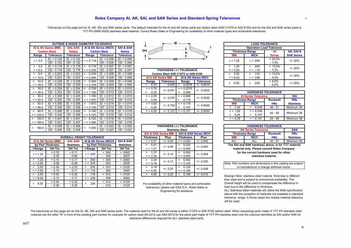
The tolerances on this page are for the AI, AK, SAI and SAK series parts. The material used for the AI and AK series is either C1075 or AISI 6150 carbon steel. When requesting parts made of 17/7 PH stainless steel material use the letter "S" in front of the existing part number for example for carbon steel AK-6312 use SAK-6312 for the same part made of 17/7 PH stainless steel Use the columns identified as SAI and/or SAK for
tolerance differences required for ALL stainless steel parts.
+/- 0,008
Desingn Note: stainless steel material thickness is different than steel and is subject to commercial availability. The Overall height will be used to compensate the difference in load due to the difference in thickness. ALL Stainless Steel materials will utilize the SAM specification above with the exception of materials not available in standard tolerance range. In those cases the closest material tolerance will be used.
> 6.00 > .236 For availability of other material types and achievable tolerances, please call GSA S.A., Rolex Sales or
Engineering for assitance.
stainless material.
+/- 0,13 +/- 0,005Note: Part numbers and dimensions in this catalog are subject
to manufacturer´s change withhowt notice.+/- 0,20
< = 1.25 < = .049 +/- 0,10 +/- 0,004 for the correct hardness used for other
40 - 51 Minimum 38by Part Thickness by Part Thickness +/- 0,08 +/- 0,003 The SAI and SAK hardness above, is for 17/7 material
material only. Please consult Rolex Company
AI & AK Series (MM) AI & AK Series (INCH) ALL ALL
HRcOVERALL HEIGHT TOLERANCE Thickness Plus Thickness Plus MM INCH HRc Stainless
SAI & SAK Series MM SAI & SAK Series INCH Thickness Range Rockwell
42 - 48 Minimum 38
> 180.0 > 7.090 THICKNESS ( t ) TOLERANCE HARDNESS TOLERANCEStainless Steel AK Series Tolerance SAK
46 - 51 Minimum 38
44 - 49 Minimum 38
MM INCH HRc Stainless+/- 0,102 +/- 0,0045
AI Series Tolerance SAIThickness Range Rockwell HRc+/- 0,076 +/- 0,0035
> 6.00 > .236 +/- 20%
+/- 0,051 +/- 0,0025 HARDNESS TOLERANCE
Range Tolerance Range Tolerance
+/- 20%AI & AK Series MM AI & AK Series INCH < = 6.00 < = .236
THICKNESS ( t ) TOLERANCE < = 3.00 < = .118Carbon Steel AISI C1075 or AISI 6150 > 3.00 > .118
+/- 20%
> 1.25 > .049 +/- 20%
< = 3.0 < = 0.118 < = 1.25 < = .049
MM INCH Series SAK Series
AI & AK Series (MM) AI & AK Series (INCH) Operation Load ToleranceCarbon Steel Carbon Steel Thickness Range AI AK, SAI &
Rolex Company AI, AK, SAI, and SAK Series and Standard Spring Tolerances
Tolerances on this page are for AI, AK, SAI and SAK series parts. The default materials for the AI and AK series parts are carbon steel (AISI C1075 or AISI 6150) and for the SAI and SAK series parts is 17/7 PH (AMS-5528) stainless steel material. Consul Rolex Sales or Engineering for availability of other material types and achievable tolerances.
OUTSIDE & INSIDE DIAMETER TOLERANCE LOAD TOLERANCE

AI SERIES DISC SPRINGSFOR BOLTING APPLICATIONS
NOM. Load f WeightBOLT in Deflec- P f per M
PART NO. * SIZE OD ID t h OH Pounds tion max. max. (in Lbs)AI-180907 # 2 0,187 0,093 0,007 0,006 0,013 10 0,005 12 0,006 0,04AI-180910 # 2 0,187 0,093 0,010 0,005 0,015 23 0,004 30 0,005 0,98AI-251209 * # 4 0,250 0,125 0,009 0,008 0,017 16 0,006 19 0,008 0,09AI-251213 * # 4 0,250 0,125 0,013 0,007 0,020 40 0,005 51 0,007 0,46AI-281315 # 6 0,281 0,138 0,015 0,008 0,023 55 0,006 70 0,008 0,20AI-311511 5/32 0,312 0,156 0,011 0,011 0,022 27 0,008 31 0,011 0,18AI-311517 * # 6 0,312 0,156 0,017 0,008 0,025 65 0,006 83 0,008 0,27AI-431322 * # 6 0,437 0,138 0,022 0,010 0,032 78 0,008 100 0,010 0,81AI-341619 * # 8 0,343 0,164 0,019 0,009 0,028 82 0,007 105 0,009 0,38AI-371915 * 3/16 0,375 0,195 0,015 0,012 0,027 50 0,009 60 0,012 0,36
AI-371918 3/16 0,375 0,195 0,018 0,010 0,028 68 0,008 87 0,010 0,41AI-371920 * 3/16 0,375 0,195 0,020 0,010 0,030 93 0,008 120 0,010 0,46AI-371930 * 3/16 0,375 0,195 0,030 0,010 0,040 323 0,008 423 0,010 0,68AI-502518 1/4 0,500 0,255 0,018 0,016 0,034 64 0,012 76 0,016 0,74AI-502519 * 1/4 0,500 0,258 0,019 0,016 0,035 76 0,012 91 0,016 0,80AI-502523 * 1/4 0,500 0,258 0,023 0,016 0,039 132 0,012 163 0,016 0,97AI-502525 * 1/4 0,500 0,255 0,025 0,013 0,038 132 0,010 168 0,013 1,03AI-502538 1/4 0,500 0,255 0,038 0,010 0,048 353 0,008 465 0,010 1,56AI-623122 * 5/16 0,625 0,317 0,022 0,020 0,042 94 0,015 111 0,020 1,42AI-623132 * 5/16 0,625 0,317 0,032 0,016 0,048 213 0,012 273 0,016 2,00AI-753227 * 5/16 0,750 0,320 0,028 0,024 0,052 148 0,018 177 0,024 2,80AI-753231 * 5/16 0,750 0,320 0,032 0,024 0,056 216 0,018 265 0,024 3,20AI-933145 * 5/16 0,937 0,317 0,045 0,022 0,067 321 0,017 412 0,022 7,78AI-683823 * 3/8 0,688 0,382 0,024 0,020 0,044 106 0,015 127 0,020 1,70AI-683827 * 3/8 0,688 0,382 0,028 0,020 0,048 165 0,015 203 0,020 2,00AI-753828 * 3/8 0,750 0,380 0,028 0,023 0,051 152 0,017 183 0,023 2,60AI-753831 * 3/8 0,750 0,382 0,032 0,020 0,052 190 0,015 239 0,020 2,90AI-753834 3/8 0,750 0,380 0,034 0,021 0,055 241 0,016 302 0,021 3,16AI-753835 * 3/8 0,750 0,382 0,035 0,022 0,057 277 0,017 348 0,022 3,30AI-753840 * 3/8 0,750 0,382 0,040 0,019 0,059 350 0,014 450 0,019 4,50AI-753856 * 3/8 0,750 0,380 0,056 0,014 0,070 697 0,011 920 0,014 5,20AI-953847 * 3/8 0,950 0,380 0,047 0,023 0,070 384 0,017 493 0,023 7,92AI-104435 7/16 1,000 0,445 0,035 0,032 0,067 222 0,024 262 0,032 6,30AI-104439 * 7/16 1,000 0,445 0,039 0,032 0,071 303 0,024 364 0,032 7,00AI-104449 * 7/16 1,000 0,445 0,049 0,026 0,075 462 0,020 590 0,026 9,00AI-874431 * 7/16 0,875 0,442 0,031 0,028 0,059 187 0,021 221 0,028 3,93AI-874445 * 7/16 0,875 0,442 0,045 0,022 0,067 422 0,017 541 0,022 5,70AI-105135 * 1/2 1,000 0,512 0,035 0,032 0,067 239 0,024 281 0,032 6,90AI-105139 * 1/2 1,000 0,512 0,039 0,036 0,075 377 0,027 443 0,036 7,50AI-105149 * 1/2 1,000 0,512 0,049 0,034 0,083 678 0,026 839 0,034 8,80AI-105159 * 1/2 1,000 0,512 0,059 0,028 0,087 945 0,021 1216 0,028 10,00AI-115139 * 1/2 1,100 0,512 0,039 0,036 0,075 293 0,027 344 0,036 8,30AI-115149 * 1/2 1,100 0,512 0,049 0,030 0,083 525 0,025 650 0,034 10,00AI-115159 * 1/2 1,100 0,512 0,059 0,028 0,087 731 0,021 941 0,028 13,00AI-105173 * 1/2 1,000 0,512 0,073 0,018 0,091 1121 0,014 1480 0,018 11,97AI-115638 9/16 1,125 0,567 0,038 0,035 0,073 261 0,026 306 0,035 7,97AI-115656 9/16 1,125 0,567 0,056 0,028 0,084 622 0,021 797 0,028 11,50AI-126340 * 5/8 1,250 0,630 0,040 0,042 0,082 307 0,031 348 0,042 13,00AI-126362 * 5/8 1,250 0,630 0,062 0,030 0,092 730 0,022 938 0,030 15,00AI-126389 * 5/8 1,250 0,630 0,089 0,022 0,111 1570 0,017 2073 0,022 23,00AI-136349 * 5/8 1,375 0,637 0,049 0,046 0,095 475 0,034 555 0,046 16,00AI-136359 * 5/8 1,375 0,637 0,059 0,043 0,102 745 0,032 915 0,043 20,00AI-136378 * 5/8 1,375 0,637 0,078 0,032 0,110 1223 0,024 1588 0,032 26,00
* = Parts normally stocked
pg18
DIMENSIONAL CHARACTERISTICS Deflection = .75h Deflection = Flat
INCHES

AI SERIES DISC SPRINGSFOR BOLTING APPLICATIONS
NOM. Load f WeightBOLT in Deflec- P f per M
PART NO. * SIZE OD ID t h OH Pounds tion max. max. (in Lbs)AI-136944 11/16 1,375 0,692 0,045 0,044 0,089 370 0,033 428 0,044 14,00AI-136967 11/16 1,375 0,692 0,067 0,034 0,101 865 0,025 1108 0,034 23,00AI-157545 * 3/4 1,500 0,755 0,045 0,048 0,093 346 0,036 391 0,048 16,00AI-157572 * 3/4 1,500 0,755 0,072 0,037 0,109 982 0,028 1256 0,037 18,00AI-157659 * 3/4 1,500 0,761 0,059 0,055 0,114 883 0,041 1034 0,055 22,00AI-157678 * 3/4 1,500 0,761 0,078 0,044 0,122 1523 0,033 1932 0,044 29,00AI-157698 * 3/4 1,500 0,761 0,098 0,036 0,134 2427 0,027 3167 0,036 37,00AI-1575107 * 3/4 1,500 0,755 0,107 0,027 0,134 2326 0,020 3070 0,027 39,00AI-178885 * 7/8 1,750 0,880 0,085 0,043 0,128 1377 0,032 1764 0,043 36,00AI-201065 * 1.0 2,000 1,016 0,065 0,065 0,130 788 0,049 906 0,065 38,00AI-201078 * 1.0 2,000 1,016 0,078 0,060 0,138 1195 0,045 1455 0,060 52,00AI-201098 * 1.0 2,000 1,016 0,098 0,060 0,158 2329 0,045 2929 0,060 65,00AI-201011 * 1.0 2,000 1,016 0,118 0,047 0,165 3101 0,035 4032 0,047 78,00AI-231078 * 1.0 2,375 1,016 0,078 0,079 0,157 1085 0,059 1245 0,079 81,00AI-231098 1.0 2,375 1,016 0,098 0,079 0,177 2066 0,059 2497 0,079 101,00AI-231011 * 1.0 2,375 1,016 0,118 0,063 0,181 2742 0,047 3497 0,063 121,00AI-251280 * 1 1/4 2,500 1,250 0,080 0,080 0,160 1143 0,060 1315 0,080 74,00AI-251212 * 1 1/4 2,500 1,250 0,120 0,060 0,180 2635 0,045 3379 0,060 122,00
* = Parts normally stocked
Note: Disc springs are tested only at f = .75h P = load at flat in lbs. f = deflection in inches.
METODO PARA CALCULAR CARGA Y TORQUE DEL PERNO
Carga del Perno = (C x Area Empaquetadura del Anillo (sp.in.) x Sistema de Presion (psi)Requerido Numero de Perno
TORQUE (ft./lbs.) = ( ,2 x Carga Dinamica (Load in Pounds) x Diametro del Perno (pulgadas)12
Use 0.15 si el Hilo o la Tuerca son Zincadas ( Use 0.2 si la junta es lubricada)
pg19
DIMENSIONAL CHARACTERISTICS Deflection = .75h Deflection = Flat
INCHES

SP Series BellevilleSprings for heavy bolted sections
Load WeightRef. Ref. Flat per M Metric IMPORTANT NOTICE: SP Series springs
Part No. * OD ID t OH 1) OH 2) (in lbs.) (in lbs.) Size are not pre-stressed. They are designedSP-52203 0,197 0,087 0,012 0,020 0,016 65 0,1 M2 for static bolted applications only.SP-62704 * 0,236 0,106 0,016 0,026 0,020 146 0,2 M2.5SP-73205 * 1/8 #5 0,276 0,126 0,020 0,030 0,025 210 0,3 M3SP-83705 * #6 0,315 0,146 0,020 0,031 0,027 176 0,3 M3.5SP-94308 * 5/32 #8 0,354 0,169 0,031 0,043 0,037 590 0,7 M4SP-115310 * 3/16 #10 0,433 0,209 0,039 0,055 0,047 1070 1,3 M5SP-146412 * 1/4 0,551 0,252 0,050 0,067 0,056 1390 2,5 M6SP-177415 * 0,669 0,291 0,059 0,079 0,070 1800 4,8 M7SP-188420 * 5/16 0,709 0,331 0,078 0,102 0,088 4755 6,9 M8SP-218425 * 5/16 0,827 0,331 0,098 0,118 0,108 5345 12,5 M8SP-231120 * 3/8 0,906 0,413 0,078 0,106 0,094 3200 11,4 M10SP-241130 * 3/8 0,945 0,413 0,118 0,140 0,130 8000 18,9 M10SP-291325 * 1/2 1,142 0,512 0,098 0,130 0,116 4700 22,9 M12SP-321335 * 1/2 1,260 0,512 0,138 0,169 0,156 9900 40,0 M12SP-351530 9/16 1,378 0,591 0,118 0,157 0,141 6500 40,7 M14SP-391540 9/16 1,535 0,591 0,157 0,197 0,181 12000 70,0 M14SP-391735 * 5/8 1,535 0,669 0,138 0,185 0,162 10000 58,5 M16SP-421740 * 5/8 1,654 0,669 0,157 0,204 0,201 13000 90,0 M16SP-471950 1,850 0,748 0,197 0,244 0,222 20000 125,0 M18SP-522160 * 3/4 2,047 0,827 0,236 0,287 0,246 31000 159,0 M20SP-562360 7/8 2,205 0,906 0,236 0,311 0,268 40276 212,0 M22SP-622565 2,441 0,984 0,256 0,335 0,291 43600 284,0 M24SP-702870 * 1 2,756 1,102 0,276 0,362 0,317 46000 392,0 M27SP-773175 1 1/8 3,031 1,220 0,295 0,386 0,343 49000 508,0 M301) When delivered. 2) After first loading * = Parts normally stocked
TORQUE (ft./lbs.) ( ,2 x Carga x Diametro del Perno (pulgadas)12
Use 0.15 si el Hilo o la Tuerca son Zincadas ( Use 0.2 si la junta es lubricada)
Part thickness is subject to material availability. Parts are be adjusted to produce flat loads indicated.
NationalUSS High StrengthStainless Steel Flat Washers
Larger sizes are available on requestBolt
Diameter Ref. Ref. Ref.National Part# * Size ID OD THSFW-753163 * 1/4" 5/16" 3/4" 0.063"SFW-873778 * 5/16" 3/8" 7/8" 0.078"SFW-104378 * 3/8" 7/16" 1" 0.078"SFW-125078 * 7/16" 1/2" 1 1/4" 0.078"SFW-135678 * 1/2" 9/16" 1 3/8" 0.078"SFW-188290 9/16" 5/8" 1 1/2" 0.090"SFW-1768120 * 5/8" 11/16" 1 3/4” 0.120"SFW-2081131 * 3/4" 13/16" 2" 0.131"SFW-2010131 1" 1 1/16" 2" 0.131"
* = Parts normally stocked
pg 20
These washers are made of 17/7 precipitation hardened (PH) stainless steel, heat reated to Rockwell C40-48 hardness. Provide the strength of heat-treated steel and the corrosion resistance of a stainless steel. Can be used in atmospheres where plain steel, no matter how well plated, will not survive.
A 'K' factor of .2 was used for the dry torque calculation. Use .15 if lubricated.The basic metric formula used for foot pounds is T = K(D/12)P (T = torque,
K = K factor for the coefficient of friction, and D = normal bolt diameter)
Notes: SP Belleville Springs are available in stainless 17/7 PH. Many sizes are in stock - Inquire
TOLERANCE in INCHES OD-PLUS .000/Minus 1.5% x OD with a minimum of .005 ID-Minus .005/Plus 1.5% ID with a minimun of .005 THICKNESS- tickness is subject to mil-run tolerances OH- Is a reference and used to control the needed load LOAD-Plus/Minus 20% of nominal shown
Nominal Inch DimensionsBoltSize

SPRING DISCSFOR FLANGE APPLICATIONS(17/7 PH STAINLESS STEEL)
Nominal @ Flat DryBolt Load TorqueSize Ref. in to Flat
Part No. * (inch) OD ID t OH Pounds (Ft. lbs.)FL-388 * 3/8 0,714 0,390 0,080 0,086 1200 8FL-716 7/16 0,820 0,452 0,080 0,097 2800 20FL-889 * 1/2 0,900 0,515 0,089 0,100 2100 18FL-10125 * 5/8 1,145 0,656 0,125 0,143 6000 63FL-12131 * 3/4 1,365 0,781 0,131 0,150 5100 64FL-14160 * 7/8 1,585 0,906 0,160 0,180 7100 104FL-16168 * 1 1,805 1,032 0,168 0,195 8600 143FL-18187 * 1 1/8 2,020 1,156 0,187 0,217 10600 199FL-20190 * 1 1/4 2,240 1,281 0,190 0,225 10500 219FL-22250 * 1 3/8 2,450 1,406 0,250 0,290 23000 527FL-24250 * 1 1/2 2,680 1,531 0,250 0,290 19000 475FL-26262 * 1 5/8 2,960 1,687 0,262 0,307 20000 542FL-28281 1 3/4 3,170 1,812 0,281 0,329 23000 671FL-30300 * 1 7/8 3,380 1,937 0,300 0,353 28000 875FL-32318 * 2 3,600 2,062 0,318 0,375 32000 1067FL-36356 2 1/4 4,040 2,312 0,356 0,418 39000 1463FL-40394 * 2 1/2 4,470 2,562 0,394 0,464 48000 2000
* = Parts mormally stocked
TYPICAL APPLICATION
Nominal DryBolt Load TorqueSize Ref. @ Flat to Flat
Part No. (mm) OD ID t OH Newtons N/MeterMFL-8050 * 8 15 8,4 1,25 1,70 6000 9,6MFL-8078 * 8 15 8,4 2,00 2,30 17000 27,2MFL-10078 * 10 18 10,4 2,00 2,30 11000 22,0MFL-12090 * 12 22 12,4 2,30 2,60 13000 31,2MFL-14098 * 14 25 14,4 2,50 2,95 18000 50,4MFL-20160 * 20 36 20,8 4,00 4,60 43000 172,0MFL-24160 * 24 43 24,8 4,00 4,80 39000 187,2MFL-27168 * 27 49 27,8 4,30 5,00 40000 216,0MFL-30190 * 30 54 30,8 4,80 5,60 42000 252,0MFL-36250 36 68 36,8 6,40 7,50 92000 662,4MFL-39250 * 39 70 39,6 6,40 7,50 91000 709,8
* = Parts mormally stocked STACK AND CROSS-SECTION
.
pg 21
K = K factor for the coefficient of friction, and D = normal bolt diameter)
FL and MFL Spring Series Tolerance
METRIC DimensionsMilimeters (MM)
A 'K' factor of .2 was used for the dry torque calculation. Use .15 if lubricated.The basic metric formula used for Newtons per meter is T = K(D/1000)P (T = torque,
INCH Dimensions
A 'K' factor of .2 was used for the dry torque calculation. Use .15 if lubricated.The basic metric formula used for foot pounds is T = K(D/12)P (T = torque,
K = K factor for the coefficient of friction, and D = normal bolt diameter)

pg 22

pg 23

pg 24

pg 25

pg 26

pg 27

pg 28

pg 29

NDS Series Disc Springs .
H11/H13 “NDS” FLANGE DISC SPRINGSNominal Deflection Load Torque Torque
Bolt @ @ Dry LubedPart No. Size ID OD t Flat Flat Ft. lbs. Ft. lbs.
NDS-1-60 1/2 0,515 1,011 0,148 0,014 8.500 71 53NDS-1-45 1/2 0,515 1,011 0,140 0,010 6.400 53 40NDS-1-30 1/2 0,515 1,011 0,130 0,010 4.200 35 26NDS-2-60 5/8 0,644 1,148 0,187 0,012 13.500 141 105NDS-2-45 5/8 0,644 1,148 0,180 0,011 9.900 103 77NDS-2-30 5/8 0,644 1,148 0,152 0,012 6.500 68 51NDS-3-60 3/4 0,773 1,370 0,224 0,015 20.000 250 188NDS-3-45 3/4 0,773 1,370 0,220 0,012 15.000 188 141NDS-3-30 3/4 0,773 1,370 0,190 0,013 9.700 121 91NDS-4-60 7/8 0,901 1,590 0,280 0,015 28.000 408 306NDS-4-45 7/8 0,901 1,590 0,265 0,013 20.000 292 219NDS-4-30 7/8 0,901 1,590 0,220 0,015 13.000 190 142NDS-5-60 1 1,030 1,810 0,316 0,018 36.000 600 450NDS-5-45 1 1,030 1,810 0,305 0,015 27.000 450 338NDS-5-30 1 1,030 1,810 0,260 0,016 18.000 300 225NDS-6-60 1 1/8 1,155 2,025 0,370 0,018 47.000 881 661NDS-6-45 1 1/8 1,155 2,025 0,345 0,017 35.000 656 492NDS-6-30 1 1/8 1,155 2,025 0,285 0,020 23.000 431 323NDS-7-60 1 1/4 1,281 2,310 0,405 0,023 60.000 1.250 938NDS-7-45 1 1/4 1,281 2,310 0,395 0,019 45.000 938 703NDS-7-30 1 1/4 1,281 2,310 0,325 0,023 30.000 625 469NDS-8-60 1 3/8 1,406 2,470 0,446 0,024 74.000 1.696 1.272NDS-8-45 1 3/8 1,406 2,470 0,440 0,019 55.000 1.260 945NDS-8-30 1 3/8 1,406 2,470 0,358 0,023 36.000 825 619NDS-9-60 1 1/2 1,531 2,680 0,513 0,024 89.000 2.225 1.669NDS-9-45 1 1/2 1,531 2,680 0,503 0,025 79.000 1.975 1.481NDS-9-30 1 1/2 1,531 2,680 0,400 0,024 44.000 1.100 825NDS-10-60 1 5/8 1,649 2,950 0,542 0,028 106.000 2.871 2.153NDS-10-45 1 5/8 1,649 2,950 0,513 0,025 80.000 2.167 1.625NDS-10-30 1 5/8 1,649 2,950 0,436 0,027 53.000 1.435 1.077NDS-11-60 1 3/4 1,774 3,170 0,593 0,029 125.000 3.646 2.734NDS-11-45 1 3/4 1,774 3,170 0,550 0,027 92.000 2.683 2.013NDS-11-30 1 3/4 1,774 3,170 0,470 0,029 60.000 1.750 1.313NDS-12-60 1 7/8 1,899 3,389 0,618 0,030 128.000 4.000 3.000NDS-12-45 1 7/8 1,899 3,389 0,597 0,028 107.000 3.344 2.508NDS-12-30 1 7/8 1,899 3,389 0,510 0,030 70.000 2.188 1.641NDS-13-60 2 2,024 3,600 0,636 0,032 132.000 4.400 3.300NDS-13-45 2 2,024 3,600 0,628 0,031 120.000 4.000 3.000NDS-13-30 2 2,024 3,600 0,545 0,032 83.000 2.767 2.075NDS-14-60 2 1/4 2,281 4,040 0,725 0,036 169.000 6.338 4.753NDS-14-45 2 1/4 2,281 4,040 0,716 0,032 155.000 5.813 4.359NDS-14-30 2 1/4 2,281 4,040 0,615 0,036 105.000 3.938 2.953NDS-l5-60 2 1/2 2,531 4,483 0,810 0,038 210.000 8.750 6.563NDS-15-45 2 1/2 2,531 4,483 0,795 0,038 196.000 8.167 6.125NDS-l5-30 2 1/2 2,531 4,483 0,695 0,038 130.000 5.417 4.063NDS-16-60 2 3/4 2,781 4,920 0,880 0,045 260.000 11.917 8.938NDS-16-45 2 3/4 2,781 4,920 0,875 0,042 240.000 11.000 8.250NDS-16-30 2 3/4 2,781 4,920 0,755 0,045 164.000 7.517 5.638NDS-17-60 3 3,031 5,360 0,984 0,046 310.000 15.500 11.625NDS-17-45 3 3,031 5,360 0,975 0,042 290.000 14.500 10.875NDS-17-30 3 3,031 5,360 0,835 0,046 190.000 9.500 7.125
pg 30
Inch Dimensions
A 'K' factor of .2 was used for the dry torque calculation and .15 for lubricated..The basic formula used is T = K(D/12)P (T = torque, K = K factor for the coefficient
Flange Disc Springs are precision machined on all surfaces with well
rounded edges
of friction, and D = normal bolt diameter)

.
AK SERIES DISC SPRINGSFOR USE WITH BALL BEARINGS
Milimeters (MM)OD ID t h OH h/t Load kg mm
623 EL-3 9,8 6,2 0,20 0,20 0,40 l.00 2,5 0,15624 EL-4 12,8 7,2 0,25 0,25 0,50 l.00 3,1 0,19625 634 EL-5 15,8 8,2 0,25 0,30 0,55 1,20 2,4 0,23626 635 EL-6 18,8 9,2 0,30 0,35 0,65 1,17 3,3 0,26607 EL-7 18,8 10,2 0,35 0,35 0,70 1,00 5,3 0,26608 627 EL-8 21,8 12,3 0,35 0,40 0,75 1,14 4,8 0,30609 EL-9 23,7 14,3 0,40 0,50 0,90 1,25 8,4 0,386000 629 25,7 14,3 0,40 0,50 0,90 1,25 6,6 0,386001 27,7 17,3 0,40 0,60 1,00 1,50 8,3 0,456200 29,7 17,4 0,40 0,70 1,10 1,75 8,6 0,536002 6201 31,7 20,4 0,40 0,70 1,10 1,75 8,4 0,536300 34,6 20,4 0,40 0,70 1,10 1,75 6,4 0,536003 6202 34,6 22,4 0,50 0,70 1,20 1,40 12,4 0,536301 36,6 20,4 0,50 0,80 1,30 1,60 11,5 0,606203 39,6 25,5 0,50 0,80 1,30 1,60 11,5 0,606004 6302 41,6 25,5 0,50 0,90 1,40 1,80 11,8 0,686005 6204 6303 46,5 30,5 0,60 0,91 1,50 1,52 16,0 0,686205 6304 51,5 35,3 0,60 0,91 1,50 1,52 14,1 0,686006 54,5 40,5 0,60 0,91 1,50 1,52 14,7 0,686007 6206 6305 61,5 40,5 0,70 1,10 1,80 l.57 18,3 0,836008 67,5 50,5 0,70 l.00 1,70 1,43 16,8 0,756306 71,5 45,5 0,70 1,40 2,10 2,00 19,3 1,056207 71,5 50,5 0,70 1,41 2,10 2,01 22,8 1,056009 74,5 55,5 0,80 1,11 1,90 1,39 22,0 0,836307 79,5 50,5 0,80 1,51 2,30 1,89 23,7 1,136010 6208 79,5 55,5 0,80 1,51 2,30 1,89 27,5 1,136209 84,5 60,5 0,90 1,61 2,50 1,79 37,4 1,216308 89,5 60,5 0,90 1,61 2,50 1,79 29,9 I .206011 6210 89,5 65,5 0,90 1,61 2,50 1,79 34,9 1,216012 94,5 75,5 1,00 1,21 2,20 1,21 33,9 0,916309 99,0 65,5 1,00 1,60 2,60 1,60 30,4 1,206013 6211 99,0 70,5 1,00 1,61 2,60 1,61 34,6 1,216310 109,0 70,5 1,25 1,45 2,70 1,16 37,1 1,096014 6212 109,0 75,5 1,25 1,46 2,70 1,16 41,3 1,096015 114,0 90,5 1,25 1,21 2,45 0,97 41,5 0,916311 119,0 75,5 1,25 1,55 2,80 1,24 33,1 1,166213 119,0 85,5 1,25 1,55 2,80 1,24 40,7 1,176016 6214 124,0 90,5 1,25 1,76 3,00 1,41 46,2 1,326312 129,0 85,5 1,25 1,96 3,20 l.57 42,0 1,476017 6215 129,0 95,5 1,25 1,96 3,20 l.57 52,0 1,476313 139,0 90,5 1,25 2,01 3,25 1,61 36,7 1,506018 6216 139,0 101,0 1,25 2,01 3,25 1,61 44,6 1,516314 149,0 95,5 1,50 1,70 3,20 1,13 39,4 1,286020 6217 149,0 106,0 1,50 1,70 3,20 1,13 46,7 1,286315 159,0 101,0 l.50 2,00 3,50 1,33 42.8. 1,506021 6218 159,0 111,0 1,50 2,00 3,50 1,33 49,5 1,506316 169,0 111,0 1,50 2,30 3,80 1,53 48,8 1,736022 6219 169,0 121,0 1,50 2,31 3,80 1,54 56,7 1,736317 179,0 121,0 2,00 2,21 4,20 1,11 89,7 1,666024 6220 179,0 126,0 2,00 2,21 4,20 1,11 96,4 1,666318 189,0 121,0 2,00 2,31 4,30 1,16 78,6 1,736221 189,0 131,0 2,00 2,31 4,30 1,16 88,9 1,73
pg 31
Belleville offers a specially designed series of disc spring for use with ball bearing installed between two ballbearings, disc springs assure perfect positioning of the bearings with no side play. They may be used toprovide precise bearing preload and proper tension, extending life of bearings and eliminating excessiverunning noise.
SIZE
BALL METRIC DIMENSIONS Deflection BEARING @ f =.75h
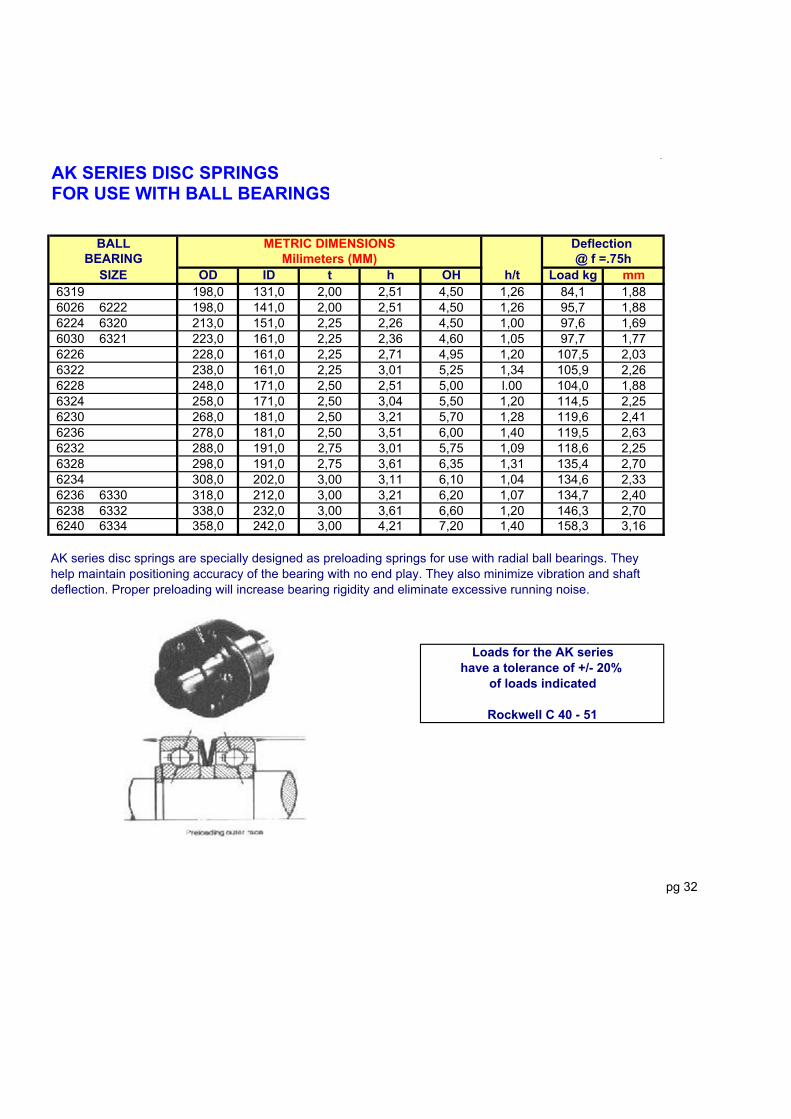
.
AK SERIES DISC SPRINGSFOR USE WITH BALL BEARINGS
Milimeters (MM)OD ID t h OH h/t Load kg mm
6319 198,0 131,0 2,00 2,51 4,50 1,26 84,1 1,886026 6222 198,0 141,0 2,00 2,51 4,50 1,26 95,7 1,886224 6320 213,0 151,0 2,25 2,26 4,50 1,00 97,6 1,696030 6321 223,0 161,0 2,25 2,36 4,60 1,05 97,7 1,776226 228,0 161,0 2,25 2,71 4,95 1,20 107,5 2,036322 238,0 161,0 2,25 3,01 5,25 1,34 105,9 2,266228 248,0 171,0 2,50 2,51 5,00 l.00 104,0 1,886324 258,0 171,0 2,50 3,04 5,50 1,20 114,5 2,256230 268,0 181,0 2,50 3,21 5,70 1,28 119,6 2,416236 278,0 181,0 2,50 3,51 6,00 1,40 119,5 2,636232 288,0 191,0 2,75 3,01 5,75 1,09 118,6 2,256328 298,0 191,0 2,75 3,61 6,35 1,31 135,4 2,706234 308,0 202,0 3,00 3,11 6,10 1,04 134,6 2,336236 6330 318,0 212,0 3,00 3,21 6,20 1,07 134,7 2,406238 6332 338,0 232,0 3,00 3,61 6,60 1,20 146,3 2,706240 6334 358,0 242,0 3,00 4,21 7,20 1,40 158,3 3,16
pg 32
Rockwell C 40 - 51
SIZE
Loads for the AK serieshave a tolerance of +/- 20%
of loads indicated
AK series disc springs are specially designed as preloading springs for use with radial ball bearings. They help maintain positioning accuracy of the bearing with no end play. They also minimize vibration and shaft deflection. Proper preloading will increase bearing rigidity and eliminate excessive running noise.
BALL METRIC DIMENSIONS Deflection BEARING @ f =.75h

.
AK SERIES DISC SPRINGSFOR USE WITH BALL BEARINGS
OD ID t h OH h/t Load lbs InchR-2 0,366 0,228 0,0079 0,0080 0,0158 1,010 5,9 0,0060623 EL-3 0,386 0,244 0,0079 0,0080 0,0158 1,010 5,4 0,0060R-3 0,492 0,319 0,0098 0,0100 0,0197 1,020 8,3 0,0075624 EL-4 0,504 0,283 0,0098 0,0099 0,0197 1,010 6,7 0,0075R.4 R.4 0,618 0,406 0,0098 0,0120 0,0217 1,220 6,8 0,0090625 634 EL-5 0,622 0,323 0,0098 0,0119 0,0217 1,220 5,3 0,0089626 635 EL-6 0,740 0,362 0,0118 0,0138 0,0256 1,170 7,2 0,0104607 EL-7 0,740 0,402 0,0138 0,0138 0,0276 1,000 11,8 0,0104608 627 EL-8 0,858 0,484 0,0138 0,0157 0,0295 1,140 10,7 0,0118R-6 R-6 0,862 0,539 0,0138 0,0158 0,0295 1,140 11,8 0,0118609 EL-9 0,933 0,563 0,0157 0,0198 0,0354 1,260 18,5 0,01486000 629 1,012 0,563 0,0157 0,0198 0,0354 1,260 14,5 0,01486001 1,091 0,681 0,0157 0,0238 0,0394 1,520 18,4 0,0179R-8 1,110 0,724 0,0157 0,0278 0,0433 1,770 24,1 0,02086200 1,169 0,685 0,0157 0,0277 0,0433 1,770 19,0 0,02086002 6201 1,248 0,803 0,0157 0,0277 0,0433 1,770 18,6 0,0208R-10 1,358 1,000 0,0197 0,0277 0,0472 1,410 34,8 0,02086300 1,362 0,803 0,0157 0,0277 0,0433 1,760 14,1 0,02086003 6202 1,362 0,882 0,0197 0,0276 0,0472 1,400 27,3 0,02076301 1,441 0,803 0,0197 0,0316 0,0512 1,600 25,5 0,02376203 1,559 1,004 0,0197 0,0316 0,0512 1,610 25,3 0,02376004 6302 1,638 1,004 0,0197 0,0355 0,0551 1,800 26,1 0,02666005 6204 6303 1,831 1,201 0,0236 0,0357 0,0591 1,510 35,3 0,02676205 6304 2,028 1,398 0,0236 0,0357 0,0591 1,510 31,1 0,02676006 2,146 1,594 0,0236 0,0357 0,0591 1,510 32,5 0,02686007 6206 6305 2,421 1,594 0,0276 0,0434 0,0708 1,570 40,3 0,03256008 2,657 1,988 0,0276 0,0395 0,0669 1,430 37,1 0,02966306 2,815 1,791 0,0276 0,0553 0,0827 2,000 42,5 0,04146207 2,815 1,988 0,0276 0,0554 0,0827 2,010 50,3 0,04156009 2,933 2,185 0,0315 0,0435 0,0748 1,380 48,5 0,03266307 3,130 1,988 0,0315 0,0593 0,0905 1,880 52,2 0,04456010 6208 3,130 2,185 0,0315 0,0594 0,0906 1,880 60,6 0,04456209 3,327 2,382 0,0354 0,0633 0,0984 1,790 82,4 0,04756308 3,524 2,382 0,0354 0,0632 0,0984 1,790 65,9 0,04746011 6210 3,524 2,579 0,0354 0,0633 0,0984 1,790 76,9 0,04756012 3,720 2,972 0,0394 0,0475 0,0866 1,210 74,8 0,03566309 3,898 2,579 0,0394 0,0632 0,1024 1,600 67,1 0,04746013 3,898 2,776 0,0394 0,0633 0,1024 1,610 76,4 0,04746310 4,291 2,776 0,0492 0,0572 0,1063 1,160 81,7 0,04296014 6212 4,291 2,972 0,0492 0,0573 0,1063 1,160 91,1 0,04306015 4,488 3,563 0,0492 0,0476 0,0965 0,970 91,4 0,03576311 4,685 2,972 0,0492 0,0611 0,1102 1,240 73,0 0,04586213 4,685 3,366 0,0492 0,0612 0,1102 1,240 89,8 0,04596016 6214 4,882 3,563 0,0492 0,0692 0,1181 1,410 101,9 0,05196312 5,079 3,366 0,0492 0,0770 0,1260 1,570 92,7 0,05786017 6215 5,079 3,760 0,0492 0,0771 0,1260 1,570 114,7 0,05796313 5,472 3,563 0,0492 0,0790 0,1280 1,610 80,9 0,05926018 6216 5,472 3,976 0,0492 0,0791 0,1280 1,610 98,4 0,05936314 6314 5,866 3,760 0,0591 0,0670 0,1260 1,130 86,8 0,05036020 6217 5,866 4,173 0,0591 0,0671 0,1260 1,140 103,0 0,05036315 6,260 3,976 0,0591 0,0788 0,1378 1,330 94,3 0,05916021 6218 6,260 4,370 0,0591 0,0789 0,1378 1,340 109,2 0,05926316 6,654 4,370 0,0591 0,0907 0,1496 1,530 107,5 0,0680
pg 33
SIZE
BALL INCH Dimensions Deflection BEARING @ f =.75h

.
AK SERIES DISC SPRINGSFOR USE WITH BALL BEARINGS
OD ID t h OH h/t Load lbs Inch6022 6219 6,654 4,764 0,0591 0,0908 0,1496 1,540 125,0 0,06816317 7,047 4,764 0,0787 0,0869 0,1654 1,110 197,7 0,06526024 6220 7,047 4,961 0,0787 0,0870 0,1654 1,110 212,5 0,06526318 7,441 4,764 0,0787 0,0908 0,1693 1,150 173,3 0,06816221 7,441 5,157 0,0787 0,0909 0,1693 1,150 196,1 0,06816319 7,795 5,157 0,0787 0,0987 0,1772 1,250 185,5 0,07406026 6222 7,795 5,551 0,0787 0,0988 0,1772 0,060 211,0 0,07416224 6320 8,386 5,945 0,0886 0,0888 0,1772 1,000 215,2 0,06666030 6321 8,780 6,339 0,0886 0,0928 0,1811 1,050 215,3 0,06966226 8,976 6,339 0,0886 0,1066 0,1949 1,200 237,0 0,07996322 9,370 6,339 0,0886 0,1184 0,2067 1,340 233,4 0,08886228 9,764 6,732 0,0984 0,0987 0,1969 1,000 229,3 0,07406324 10,157 6,732 0,0984 0,1183 0,2165 1,200 252,5 0,08886230 10,551 7,126 0,0984 0,1263 0,2244 1,280 263,6 0,09476326 10,945 7,126 0,0984 0,1381 0,2362 1,400 263,5 0,10356232 11,339 7,520 0,1083 0,1183 0,2264 1,090 261,5 0,08876328 11,732 7,520 0,1083 0,1419 0,2500 1,310 298,6 0,10656234 12,126 7,953 0,1181 0,1223 0,2402 1,040 296,7 0,09176236 6330 12,520 8,346 0,1181 0,1262 0,2441 1,070 297,0 0,09476238 6332 13,307 9,134 0,1181 0,1420 0,2598 1,200 322,5 0,10656240 6334 14,094 9,528 0,1181 0,1657 0,2835 1,400 348,9 0,1243
pg 34
Rockwell C 40 - 51
Preloading outer race
SIZE
Loads for the AK serieshave a tolerance of +/- 20%
of loads indicated
BALL INCH Dimensions Deflection BEARING @ f =.75h

.
Contact Belleville Spring
CalculatedMetric Bolt Max. Min. Ref. Ref. load @
No. Part No. Diameter OD ID t OH - Flat -M3 65-03-11 - 0,315 0,122 0,024 0,039 400
M3.5 65-02-52 #6 0,362 0,142 0,028 0,047 590M4 65-04-11 #8 0,402 0,161 0,039 0,059 1480M5 65-05-11 #10 0,481 0,201 0,050 0,073 2420M6 65-06-12 - 0,559 0,240 0,052 0,087 3350M6 65-06-15 - 0,559 0,240 0,043 0,067 1210M6 65-06-35 1/4 0,559 0,254 0,052 0,087 3450M8 65-08-21 5/16 0,717 0,323 0,055 0,095 2680M8 65-08-23 5/16 0,717 0,323 0,035 0,081 760- 65-09-2 1 - 0,798 0,362 0,062 0,095 3540
M10 65-10-22 3/8 0,877 0,402 0,062 0,108 3010M12 65-12-01 7/16 1,074 0,489 0,078 0,120 3510M12 65-12-71 1/2 1,074 0,512 0,078 0,120 3600M14 65-14-42 9/16 1,192 0,567 0,098 0,138 5350M15 65-16-42 5/8 1,273 0,646 0,098 0,156 7460M20 65-20-02 3/4 1,570 0,781 0,118 0,185 9000
Bolt CalculatedMetric Inch Max. Min. Ref. Ref. load @
No. Part No. Diameter OD ID t OH - Flat -3 55-03-01 - 0,244 0,122 0,024 0,037 7003 55-03-51 #6 0,284 0,140 0,028 0,043 9304 55-04-01 #8 0,323 0,162 0,032 0,045 9005 55-05-01 #10 0,402 0,201 0,039 0,059 17006 55-06-01 - 0,481 0,240 0,050 0,071 2500- 55-07-21 9/32 0,559 0,284 0,055 0,081 32008 55-08-01 5/16 0,638 0,323 0,055 0,095 380010 55-10-21 3/8 0,798 0,402 0,062 0,095 270012 55-12-41 7/16 0,955 0,489 0,062 0,102 2300
CalculatedMetric Bolt Max. Min. Ref. Ref. load @
No. Part No. Diameter OD ID t OH - Flat -3 75-03-12 - 0,402 0,122 0,024 0,047 3604 75-04-12 #8 0,559 0,161 0,039 0,071 11205 75-05-12 #10 0,638 0,201 0,050 0,085 18206 75-06-14 - 0,717 0,240 0,055 0,100 27806 75-06-36 1/4 0,717 0,254 0,055 0,100 28108 75-08-22 5/16 0,877 0,323 0,055 0,095 161010 75-10-23 3/8 1,074 0,402 0,062 0,112 198012 75-12-32 - 1,273 0,488 0,069 0,138 278012 75-12-72 1/2 1,273 0,512 0,069 0,138 2820
< pg 35
CONTACT Belleville Spring combine two important features for improved bolt connections. Their conical shape provides a reactive force and a high elasticity of spring return to compensate for developed looseeness, loss of bolt tensin due to applied surface deteroration, or movement due to thermal expansion and contaction. The hardened, serrated profile "grips" the lower surface of the bolt or nut to prevent the loss of tensin that normally occurs during extreme vibration or severe shock.
CONTACT Bellevilles come in sizes that correspond to a wide range of srew head sizes, including hex head socket screwa. They can also be used in Sems assemblies. Made of selected high quality carbon spring steel, these springs are available with mechanical zinc or tin plate.
- Flat - NOTE: Contact tolerances are as stated and loads indicated are computed. Actual loads obtained in practice car vary as much as 25% due to fluctuation in overall height tolerances.
CONTACT "Wide"INCH DIMENSIONS
CONTACT "Regular"INCH DIMENSIONS
CONTACT "Narrow"INCH DIMENSIONS